multipoint 75 / 100 - plumbase
TRANSCRIPT

1
MULTIPOINT 75 / 100
Fitting Instructions and User Guide

32
INTRODUCTIONThank you for purchasing a Heatrae Sadia Multipoint 75 / 100 unvented water heater. The Multipoint water heater is manufactured in the UK to the highest standards and has been designed to meet all the latest relevant safety specifications.
To make installation quicker and easier the Multipoint 75 / 100 water heaters incorporate an internal check valve, Expansion relief valve, expansion vessel and factory fitted temperature / pressure relief valves.
Please read and understand these instructions before installing your Multipoint water heater. Particular attention should be paid to the section headed IMPORTANT INSTALLATION POINTS.
The Multipoint unit must be installed and commissioned by a competent person. Please read and understand these instructions before installing the Multipoint unit. Following installation and commissioning, the operation of the Multipoint unit should be explained to the user and these instructions left with them for future reference.
The Multipoint unit is not intended for use by persons (including children) with reduced physical, sensory or mental capabilities, or lack of experience and knowledge, unless they have been given supervision or instruction concerning the use of the appliance by a person responsible for their safety.
Children should be supervised to ensure they do not play with the Multipoint unit.
The Multipoint unit does not contain any substances harmful to health; it does not contain any asbestos.
TECHNICAL SPECIFICATIONSElectrical Rating 3.0kW @ 240v / 2.8kW @ 230v 6.0kW @ 240v / 5.5kW @ 230vCapacity 75 and 100 litresWeight (100 Litre) 50Kg (empty), 160Kg (full)Weight (75 Litre) 38Kg (empty), 123Kg (full)Operating pressure 0.35 MPa (3.5 bar)Rated pressure 0.6 MPa (6.0 bar)Expansion vessel charge pressure 0.35 MPa (3.5 bar)Expansion relief valve setting 0.6 MPa (6.0 bar)Minimum supply pressure 0.08 MPa (0.8 bar)Maximum supply pressure to PRV 1.6 MPa (16.0 bar)Temperature / Pressure Relief Valve 90°C / 0.7 MPa (7.0 bar) Figure1: Multipoint Water Heater - Dimensions and Important Features
PERFORMANCE
DIMENSION A B C D
75 LITRE824911
1055843
100 LITRE982
106912131001
1 TEMPERATURE / PRESSURE RELIEF VALVES2 OUTLET3 DISCHARGE AND TUNDISH4 THERMOSTATS5 ELEMENT PLATE ONE6 CUTOUTS7 TERMINAL BLOCK8 CABLE GRIP9 EXPANSION VESSEL10 DRAIN COCK11 NON RETURN VALVE12 EXPANSION RELIEF VALVE13 ELEMENT PLATE TWO14 INLET15 INDICATOR LIGHTS
7
8 9
6
5
4
3
2
12
11
13
14
15
1
10
729565430
79
A B CD
Model
75 litre 3kW
75 litre 6kW
Heat up (minutes)
88
44
Recovery (minutes)62 (cylinder one)88 (cylinder two)31 (cylinder one)44 (cylinder two)84 (cylinder one)120 (cylinder two)42 (cylinder one)60 (cylinder two)
Heat loss in 24hr (kWh)
1.13
1.13
100 litre 3kW 120 1.27
100 litre 6kW 60 1.27

54
2.0 GENERAL REQUIREMENTS:2.1 The Multipoint must be vertically wall mounted using the wall bracket
supplied. The water connections must always be at the bottom of the unit.
2.2 Enough space should be left below the unit for pipe connections and above the unit for access to the Temperature/Pressure Relief Valves (400 mm minimum). Refer to Figure 1 and the Dimensions Table to determine a suitable position for the heater.
2.3 Ensure that the wall can support the full weight of the unit and that there are no hidden services (electricity, gas or water) below the surface of the wall.
2.4 DO NOT install where the unit may freeze.2.5 National Wiring Rules may contain restrictions concerning the
installation of these units in bathrooms.
1.0 IMPORTANT INSTALLATION POINTS1.1 The Multipoint unvented water heater is factory fitted with two
Temperature/Pressure Relief Valves which must not be removed, blocked or restricted in any way.
1.2 Expansion MUST be accommodated within the system. The Multipoint 75/100 incorporates an expansion vessel and check valve for this purpose.
1.3 The Multipoint water heater must be installed by a competent installer in accordance with Building Regulation G3 (England and Wales), Technical Standard P3 (Scotland) or Building Regulation P5 (Northern Ireland).
FAILURE TO PROVIDE ADEQUATE TEMPERATURE AND PRESSURE RELIEF WILL INVALIDATE ANY GUARANTEE AND LEAD TO A DANGEROUS INSTALLATION.
WARNING: IF WATER FLOWS FREELY FROM THE PRESSURE RELIEF VALVE OR THE TEMPERATURE/PRESSURE RELIEF VALVES, THE ELECTRICITY SUPPLY MUST BE SWITCHED OFF IMMEDIATELY. CONTACT THE HEATRAE SADIA SERVICE TEAM
3.0 WALL MOUNTING3.1 Fit the heater wall brackets to the rear of the unit using the bolts
provided (see Figure 2, step 1 below).3.2 Using Figure 1 and the dimensions table as a guide mark the positions
of the fixing points. Drill and plug the wall with suitable fixings.3.3 Fix the top two fixings first (Figure 2 step 2) followed by the bottom two
fixings (Figure 2, step 3).
NOTE: THE MULTIPOINT WATER HEATER IS HEAVY. PRIOR TO FIXTURE ENSURE THE WALL IS STRONG ENOUGH TO TAKE THE WEIGHT OF THE WATER HEATER WHEN FULL.
Figure 2: Fixture of brackets and wall mounting
1 2
3
COMPONENT CHECKLISTBefore commencing installation please check that the following components have been supplied in the Installation Kit:• Combined pressure reducing valve and strainer (x1)• Tundish (x1) • Mounting brackets (x2)• Mounting bracket fixing bolts (x6)
76
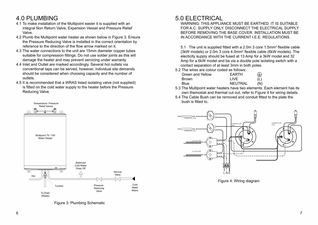
5.0 ELECTRICALWARNING: THIS APPLIANCE MUST BE EARTHED. IT IS SUITABLE FOR A.C. SUPPLY ONLY. DISCONNECT THE ELECTRICAL SUPPLY BEFORE REMOVING THE BASE COVER. INSTALLATION MUST BE IN ACCORDANCE WITH THE CURRENT I.E.E. REGULATIONS.
5.1 The unit is supplied fitted with a 2.0m 3 core 1.5mm2 flexible cable (3kW models) or 2.0m 3 core 4.0mm2 flexible cable (6kW models). The electicity supply should be fused at 13 Amp for a 3kW model and 32 Amp for a 6kW model and be via a double pole isolating switch with a contact separation of at least 3mm in both poles.
5.2 The wires are colour coded as follows: Green and Yellow EARTH Brown LIVE (L) Blue NEUTRAL (N)5.3 The Multipoint water heaters have two elements. Each element has its
own themostat and thermal cut out, refer to Figure 4 for wiring details.5.4 The Cable Bush can be removed and conduit fitted to the plate the
bush is fitted to.
4.0 PLUMBING4.1 To make installation of the Multipoint easier it is supplied with an
integral Non Return Valve, Expansion Vessel and Pressure Relief Valve.
4.2 Plumb the Multipoint water heater as shown below in Figure 3. Ensure the Pressure Reducing Valve is installed in the correct orientation by reference to the direction of the flow arrow marked on it.
4.3 The water connections to the unit are 15mm diameter copper tubes suitable for compression fittings. Do not use solder joints as this will damage the heater and may prevent servicing under warranty.
4.4 Inlet and Outlet are marked accordingly. Several hot outlets via conventional taps can be served, however, individual site demands should be considered when choosing capacity and the number of outlets.
4.5 It is recommended that a WRAS listed isolating valve (not supplied) is fitted on the cold water supply to the heater before the Pressure Reducing Valve.
Figure 3: Plumbing Schematic
Figure 4: Wiring diagram
Multipoint 75 / 100Water Heater
Temperature / PressureRelief Valves
BalancedCold WaterDraw Off
Pressure Reducing
Valve
ServiceValve
ColdWaterMains
Hot
Tundish
To Drain(Waste)
CUT-OUT ONE
THERMOSTAT TWO
THERMOSTAT ONE
CUT-OUT TWO
ELEMENT PLATE TWO
ELEMENT PLATE ONE
ENL

98
6.0 DISCHARGE It is a requirement of Building Regulation G3 that any discharge from an unvented system is conveyed to where it is visible, but will not cause danger to persons in or about the building.
G3 REQUIREMENT“...there shall be precautions...to ensure that the hot water discharged from safety devices is safely conveyed to where it is visible but will not cause danger to persons in or about the building.”
The Multipont 75/100 includes a pre plumbed discharge pipe (D1) from the T&P and ERV valves to the tundish. The pre plumbed pipe terminates in a 1/2” female threaded fitting which the supplied tundish MUST be fitted to. This ensures that the location of the tundish is visible, and in the same space of the water heater as required by G3.This pipe must be left open to atmosphere and water may drip from the valve.Discharge pipe (D2) from the tundish should be plumbed in accordance with section 3.9 of G3 which is reproduced in the following sections
G3 GUIDANCE SECTION 3.9The discharge pipe (D2) from the tundish should terminate in a safe place where there is no risk to persons in the vicinity of the discharge, preferably be of metal and:1 Be at least one pipe size larger than the nominal outlet size of the safety
device unless its total equivalent hydraulic resistance exceeds that of a straight pipe 9m long i.e. discharge pipes between 9m and 18m equivalent resistance length should be at least two sizes larger than the nominal outlet size of the safety device, between 18 and 27m at least 3 sizes larger, and so on. Bends must be taken into account in calculating the flow resistance. Refer to Table 1 on page 10 and the worked example.
2 An alternative approach for sizing discharge pipes would be to follow BS 6700:1987 Specification for design installation, testing and maintenance of services supplying water for domestic use within buildings and their curtilages, Appendix E, section E2 and table 21.
3 Have a vertical section of pipe at least 300mm long, below the tundish before any elbows or bends in the pipework.
4 Be installed with a continuous fall and in a frost free enviroment.5 Have discharges visible at both the tundish and the final point of
discharge but where this is not possible or is practically difficult there should be clear visibility at one or other of these locations. Examples of acceptable discharge arrangements are:
i Ideally below a fixed grating and above the water seal in a trapped gully.ii Downward discharges at low level; i.e. up to 100mm above external
surfaces such as car parks, hard standings, grassed areas etc. are acceptable providing that where children may play or otherwise come into contact with discharges a wire cage or similar guard is positioned to prevent contact, whilst maintaining visibility.
iii Discharges at high level; e.g. into a metal hopper and metal down pipe with the end of the discharge pipe clearly visible (tundish visible or not) or onto a roof capable of withstanding high temperature discharges of water and 3m from any plastics guttering system that would collect such discharges (tundish visible).
iv Where a single pipe serves a number of discharges, such as in blocks of flats, the number served should be limited to not more than 6 systems so that any installation discharging can be traced reasonably easily. The single common discharge pipe should be at least one pipe size larger than the largest individual discharge pipe (D2) to be connected. If unvented hot water storage systems are installed where discharges from safety devices may not be apparent i.e. in dwellings occupied by blind, infirm or disabled people, consideration should be given to the installation of an electronically operated device to warn when discharge takes place.
NOTE:The discharge will consist of scalding water and steam. Asphalt, roofing felt and non-metallic rainwater goods may be damaged by such discharges.
WORKED EXAMPLE OF DISCHARGE PIPE SIZING:The example below is for a G1/2 temperature relief valve with a discharge pipe (D2) having 4 No. elbows and length of 7m from the tundish to the point of discharge.From Table 1 (overleaf):• Maximum resistance allowed for a straight length of 22mm copper dis-
charge pipe (D2) from a G1/2 temperature relief valve is 9.0m.• Subtract the resistance for 4 No. 22mm elbows at 0.8m each = 3.2m• Therefore the permitted length equates to: 5.8m• 5.8m is less than the actual length of 7m therefore calculate the next
largest size.• Maximum resistance allowed for a straight length of 28mm pipe (D2)
from a G1/2 temperature relief valves equates to 18m.• Subtract the resistance of 4 No. 28mm elbows at 1.0m each = 4.0m Therefore the maximum permitted length equates to: 14m• As the actual length is 7m, a 28mm (D2) copper pipe will be satisfactory.

1110
7.0 COMMISSIONING7.1 Do not switch on the electrical supply until the Multipoint has been filled
with water and checked for leaks.7.2 Check that all installation, electrical and discharge pipe requirements
have been met.7.3 Check that all water and electrical connections are tight.7.4 Open a hot water tap, turn on mains water supply to the Multipoint.7.5 Allow Multipoint to fill and leave hot tap running for a short while to
purge any air and flush out the pipework. Close the hot tap and check the system for leaks.
7.6 Manually test the operation of the Temperature/Pressure Relief Valves and the Pressure (expansion) Relief Valve. Ensure water flows freely from the valves and through the discharge pipes.
7.7 Switch on the electrical supply. The indicator lights will illuminate during heating. When the set temperature is reached the indicator lights will go out.
7.8 The set temperature can be adjusted by rotating the thermostat controls located inside the terminal cover. It is recommeded that both thermostats are set at position 6 (approximatley 60°C) however they can be adjusted between settings 1 to 7 (5°C to 75°C). In hard water areas it is advised that the maximum temperature is restricted to prevent build up of scale.
8.0 MAINTENANCE Little maintenance is required, however in hard water areas the unit will require periodic descaling to ensure efficient operation. To descale the unit:8.1 Switch off and disconnect the electrical supply. Turn off the water
supply to the unit.8.2 Open a hot tap to relieve any system pressure.8.3 Remove the terminal cover by removing the five supporting screws
holding it in place.8.4 Drain water by opening internal drain cocks.8.5 Unclip the expansion vessel retaining clip and locate the expansion
vessel into the nest detail at the front on the right (see Figure 6 overleaf).
8.6 Disconnect the electrical terminals to the element and the earth link to the earthing stud. Withdraw the thermostat and thermal cut-out capillary tubes from the pockets on the element plate.
8.7 Remove the element plate assembly by unscrewing the five securing screws. Tapped jacking holes are provided (NOTE: a quantity of water may still be present in the container, it is recommended that a container be placed under the unit to collect any spillage).
Table 1. Sizing of copper discharge pipe (D2) for common T&P relief valve sizes.
Figure 5. Schematic discharge pipe arrangement.
VALVE OUTLET SIZE
MINIMUM SIZE OFDISCHARGE PIPE D1
MINIMUM SIZE OFDISCHARGE PIPE D2FROM TUNDISH
MAXIMUM RESISTANCEALLOWED, EXPRESSEDAS A LENTGH OF STRAIGHT PIPE (I.E. NO ELBOWS OR BENDS
RESISTANCE CREATED BYEACH ELBOW OR BEND
G 1/2 15MM 22mm28mm35mm
UP TO 9MUP TO 18MUP TO 27M
0.8M1.0M1.4M
G 3/4 22MM 28mm35mm42mm
UP TO 9MUP TO 18MUP TO 27M
1.0M1.4M1.7M
G 1 28MM 35mm42mm54mm
UP TO 9MUP TO 18MUP TO 27M
1.4M1.7M2.3M
Fixed grating
Discharge below
(Building RegulationG3 section 3.9d givesalternative pointsof discharge)
Trappedgully
Discharge pipe (D2) from tundish,with continuous fall. See BuildingRegulation G3 section 3.9d i-iv,Table 4 and worked example
300mmminimum
500mm maximum
Metal discharge pipe (D1) fromTemperature relief valve to tundish
Tundish
Safety device(e.g. Temperaturerelief valve)

1312
The Temperature/Pressure Relief Valves and the Pressure (Expansion Relief Valve should be regularly operated to remove lime deposits and varify that it is not blocked.8.12 Manually operate the valves by twisting the cap. Ensure water flows
freely from the valves and through the discharge pipes (NOTE: the water discharged may be very hot). Ensure the valves reseat correctly when released.
8.13 Clean the strainer incorporated in the Pressure Reducing Valve. To inspect and clean the strainer turn off the mains water supply to the heater and open a hot tap to relieve the system pressure. Unscrew the black cap from the Pressure Reducing Valve and remove. The strainer will be removed with the cap. Wash any particulate matter from the strainer under clean running water. Replace the cap assembly ensuring the sealing ring is correctly fitted. Do not use any other type of sealant. Close hot tap, open mains stop cock and check for leaks.
The Expansion Vessel should have a precharge pressure of 3.5 bar (51p.s.i.).
This can reduce over time and eventually require re-charging. To do this:
8.14 Turn off water supply to the unit; open a hot tap to relieve system pressure.
8.15 Switch off and disconnect electrical supply to water heater.8.16 Remove the terminal cover by removing the five supporting screws
holding it in place.
8.17 Remove dust cap from top of Expansion Vessel.8.18 Check pre-charge pressure using a tyre pressure gauge. If the
pressure is lower than 3.5 bar (51 p.s.i.) it should be recharged using a tyre
pump (Schraeder Valve type). DO NOT OVER CHARGE. 8.19 Re-check pressure and when correct replace dust cap.8.20 Turn on mains water supply and close hot tap.
9.0 FAULT FINDINGThe Multipoint unit should give trouble free operation, however should a problem occur, the tables below should enable most faults to be identified with ease.Fault Finding should be carried out by a competent person and any re-placement parts used should be authorised Heatrae spare parts.
Figure 6. Removal of expansion vessel for maintenance puproses.
8.8 Remove any loose scale from the container. Carefully clean off any scale from the element and thermostat pocket. DO NOT clean scale from interior container walls.
8.9 Re-assemble the element plate assembly fitting a new sealing gasket. Rewire the unit with reference to Figure 4 (wiring diagram).
8.10 Repeat this for both element plate assemblies.8.11 Re-commission the unit following the INSTALLATION and
COMMISSIONING instructions.
FAULT� � � POSSIBLE CAUSES� ACTION
Water not heating� � Electrical supply fault� Check electrical supply� � � Thermal cut out tripped� Check cut outs. If they have� � � � � � operated then reset them.� � � � � � If necessary replace them.� � � � � � Check thermostats and if� � � � � � necessary replace them.� � � Thermostat setting too� Check thermostat setting.� � � low or faulty.� � Replace if necessary.Discharge of water from� Excessive mains water� Check pressure from�pressure relief valve� pressure� � � Pressure reducing valve.(continuously).� � � � � Replace if greater than�� � � � � � 3.5 bar (51psi)� � � Expansion relief valve� Replace expansion relief� � � fault� � � valve.Discharge of water from� Loss of pressure from� Check and if necessary pressure relief valve� Expansion vessel� � re charge expansion vessel�(intermittently).� � � � � pre charge pressure.Discharge of water from� Thermostat and� � Replace thermostats and Temperature/Pressure� thermal cut out fault� thermal cut outsrelief valve and/or water/steam frompressure relief valveNo water flow� � Product incorrectly� Check inlet and outlet � � � Installed� � � connections are correct.� � � � � � Check valves are installed � � � � � � in accordance with flow � � � � � � direction arrows.�� � � Mains water supply� Check mains water supply� � � not turned on.� � is turned on.� � � Blockage in main water � Check mains water supply� � � supply� � � for obstructions.� � � � � � Check Expansion relief valve."Milky water"� � Oxygenated water�� Water from a pressurised� � � � � � system releases oxygen� � � � � � bubbles when flowing. The� � � � � � milkiness will disapear � � � � � � after a short while.� � � � � �

1514
10. Indicator Light ..........................................95 607 04811. Pressure (Expansion) Relief Valve ..........95 607 73712. Check Valve .............................................95 607 98713. Gasket (pack of 10) .................................95 611 70814. Terminal Cover ........................................95 614 08615. Pressure Reducing Valve ........................95 607 989
11.0 ACCESSORIESThe heater can be used to supply several hot water outlets via conventional taps. Individual site demands should be considered when choosing capacity and the number of outlets to be served.A Thermostatic Blending Valve can be used in conjunction with the Multipoint Water Heater. Heatrae Sadia supply both TMV2 approved (Pack U3, code number 95 970 354) and TMV3 approved (Pack U7 95 970 360) Thermostatic Blending Valves.
12.0 USER INSTRUCTIONS12.1 The temperature can be adjusted by rotating the thermostat controls
located inside the terminal cover. It is recommended that both thermostats are set at position 6 (approximately 60°C) however they can be adjusted between settings 1 to 7 (5°C to 75°C).In hard water areas it is advised that the maximum temperature is restricted to prevent build up of scale. To avoid risk of freezing when the heater is not in use for long periods during the winter months, do not switch off the electrical supply and set the thermostat to its minimum position. N.B. This will not protect other system pipework.
12.2 The indicator lights will be illuminated when the unit is heating.12.3 To ensure the heater continues to operate at its optimum performance
it should be periodically maintained in accordance with the instructions given under the section headed MAINTENANCE.
12.4 IMPORTANT NOTES TO USER DO NOT BLOCK OR RESTRICT THE DISCHARGE FROM ANY
SAFETY VALVE FITTED.DO NOT TAMPER WITH ANY SAFETY VALVE FITTED.IF WATER DISCHARGES FROM ANY SAFETY VALVE FITTED SWITCH OFF THE ELECTRICAL SUPPLY TO THE UNIT IMMEDIATELY. CONTACT THE HEATRAE SADIA SERVICE TEAM (TEL: 0844 8711535) OR AN APPROVED INSTALLER. DO NOT TURN THE ELECTRICAL SUPPLY ON AGAIN UNTIL THE UNIT HAS BEEN CHECKED AND APPROVED BY A QUALIFIED INSTALLER.
10.0 SPARE PARTSThe following comprehensive list of spare parts is available for your Multipoint water heater. Please refer to the Rating Label on the side of your heater before ordering to ensure the correct spare part is obtained.
DO NOT REPLACE WITH PARTS NOT RECOMMENDED BY HEATRAE SADIA. THIS WILL INVALIDATE YOUR GUARANTEE AND MAY RENDER THE INSTALLATION DANGEROUS.
1. Temperature/Pressure Relief Valve ...........95 605 0452. Expansion Vessel ......................................95 607 0453. Fixing Bracket (75 Litre) ............................95 607 0463. Fixing Bracket (100 Litre) ..........................95 607 0474. Thermostat ................................................95 612 0195. Thermal Cut-Out .......................................95 612 0206. Element Plate Assembly - 3kW ................95 606 9266. Element Plate Assembly - 1.5 kW ............95 606 9607. Fixing Bracket Bolts (pack of 6) ................95 607 0508. Terminal Cover Screws (pack of 5) ...........95 607 0519. Flexible hose .............................................95 607 049
1
2
3
4
5
6
11
10
9
12
13
7
8
14

1636005917 issue 5
Spares StockistsFor the fast and efficient supply of spares please contact the stockists listed below.
Advanced Water Company Ltd.Unit D5 Enterprise wayVale park, EveshamWorcs, WR11 1GSTel: 01386 760066Fax: 01386 760077
Electric Water Heating Co. 2 Horsecroft Place, PinnaclesHarlow, Essex, CM19 5BTTel: 0845 0553811E-Mail: [email protected]
SPDUnits 9 & 10 Hexagon Business CentreSpringfield Road, HayesMiddlesex, UB40 0TYTel: 020 8606 3567
Parts CenterTel: 0845 2709800www.partscenter.co.uk
Newey & EyreSpecialist Products DivisionPlease contact your local branch
UK Spares Ltd.Unit 1155 Aztec West, AlmondsburyBristol, BS32 4TFTel: 01454 620500
William Wilson Ltd.Unit 3A, 780 South StreetWhiteinch, Glasgow, G14 OSYTel: 0141 434 1530
Heatrae Sadia Heating Hurricane Way Norwich NR6 6EAwww.heatraesadia.com
Service: 0844 8711535Service Fax: 0844 8711528E-mail: heatraesadiaservice
@heateam.co.uk
© 2009