multimode fiber optic wavelength division multiplexing · pdf filemultimode fiber optic...
TRANSCRIPT

I
NASA Technical Memorandum 84488
NASA-TM-84483 19820017567 "-'_"0_'__
Multimode Fiber Optic
Wavelength Division
Multiplexing
J. Larry Spencer ._
April 1982
National Aeronautics and
SpaceAdministration LANGLEYPESEAR[:,"-,CL,"GER
LangleyResearchCenter L:_,_F_'_,rJo,SAHampton, Virginia 23665 H,-,;.. _O,-1,VIRG',I'_:A
https://ntrs.nasa.gov/search.jsp?R=19820017567 2018-05-12T07:17:07+00:00Z


MULTIMODEFIBER OPTIC WAVELENGTHDIVISION MULTIPLEXING
by J. Larry SpencerNASALangley Research Center
Hampton, Virginia 23665
ABSTRACT
Optical wavelength division multiplexing (WDM) systems, with signalstransmitted on different wavelengths through a single optical fiber, canhave increased bandwidth and fault isolation properties over singlewavelength optical systems. This paper considers two WDMsystem designsthat might be used with multimode fibers and gives a general descripton ofthe components which could be used to implement the system. The componentsdescribed are sources, multiplexers, demultiplexers, and detectors.Emphasis is given to the demultiplexer technique which is the majordevelopmental component in the WDMsystem.
INTRODUCTION
Optical wavelength division multiplexing (WDM)involves thesimultaneous transmittal of information via different wavelengths oflight. The various wavelengths after generation by separate opticalsources are mixed by a multiplexer and transmitted over an opticalcommunication link. At the receiving end of the link_ the distinctwavelengths of light are separated by a demultiplexer and converted toelectrical signals by a photo detector. By using WDMa single opticalfiber will provide multiple transmission paths. WDMincreases theinformation capacity of a single optical fiber and also provides a meansfor two-way simultaneous transmission (full duplex). For a given datatransmission requirement a WDMsystem would require less optical fibers,repeaters, splices and/or connectors than a single wavelength system.
The WDMsystems also have the standard advantages of single wavelengthoptical systems such as reduced weight and cost and immunity tolightning-induced transients.
An additional attribute of WDMis that a faulty or failed transmitterwill be confined to a single communication path and will not disturb theinformation transmitted on the same fiber at different wavelengths. Thisfault containment attribute makes WDMa prime candidate for application inNASA-Langley's research program in flight crucial fault tolerant systemsfor advanced aerospace vehicles.
GENERALSYSTEMDESCRIPTIONS
Asdiscussed in the introduction, there are two general system designadvantages using WDMtechniques. The one for increasing the capacity ofthe transmission system and the second pertains to fault containment in thesystem. An N channel WDMsystem block diagram of the increased capacitytype is shown in figure I. Each input channel has an optical sourcetransmitting light at a given wavelength. The output of these sources arecombined onto a single transmission fiber using a passive multiplexer.
/V2z
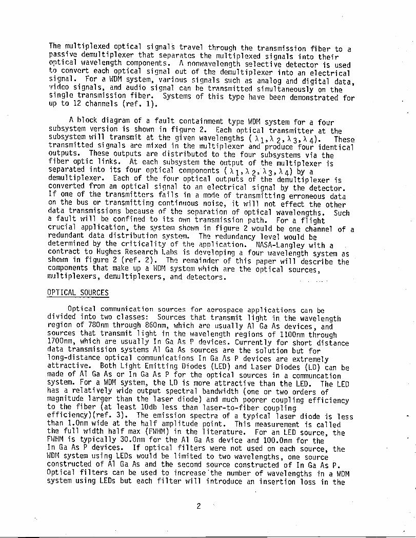
The multiplexed optical signals travel through the transmission fiber to apassive demultiplexer that separates the multiplexed signals into theiroptical wavelength components. A nonwavelength selective detector is usedto convert each optical signal out of the demultiplexer into an electricalsignal. For a WDMsystem, various signals such as analog and digital data,video signals, and audio signal can be transmitted simultaneously on thesingle transmission fiber. Systems of this type have been demonstrated forup to 12 channels (ref. 1).
A block diagram of a fault containment type WDMsystem for a foursubsystem version is shown in figure 2. Each optical transmitter at thesubsystem will transmit at the given wavelengths (_i,_2,_3,_4). Thesetransmitted signals are mixed in the multiplexer and produce four identicaloutputs. These outputs are distributed to the four subsystems via thefiber optic links. At each subsystem the output of the multiplexer isseparated into its four optical components (XI,_2, _3,_4) by ademultiplexer. Each of the four optical outputs of the demultiplexer isconverted from an optical signal to an electrical signal by the detector.If one of the transmitters fails in a mode of transmitting erroneous dataon the bus or transmitting continuous noise, it will not effect the otherdata transmissions because of the separation of optical wavelengths. Sucha fault will be confined to its own transmission path. For a flightcrucial application, the system shown in figure 2 would be one channel of aredundant data distribution system. The redundancy level would bedetermined by the criticality of the application. I_ASA-Langley with acontract to Hughes Research Labs is developing a four wavelength system asshown in figure 2 (ref. 2). The remainder of this paper will describe thecomponents that make up a WDMsystem which are the optical sources,multiplexers, demultiplexers, and detectors. .......
OPTICALSOURCES
Optical communication sources for aerospace applications can bedivided into two classes: Sources that transmit light in the wavelengthregion of 780nmthrough 860nm, which are usually A1 Ga As devices, andsources that transmit light in the wavelength regions of llOOnm through1700nm, which are usually In Ga As P devices. Currently for short distancedata transmission systems A1Ga As sources are the solution but forlong-distance optical communications In Ga As P devices are extremelyattractive. Both Light Emitting Diodes (LED) and Laser Diodes (LD) can bemade of A1 Ga As or In Ga As P for the optical sources in a communcationsystem. For a WDMsystem, the LD is more attractive than the LED. The LEDhas a relatively wide output spectral bandwidth (one or two orders ofmagnitude larger than the laser diode) and much poorer coupling efficiencyto the fiber (at least lOdb less than laser-to-fiber couplingefficiency)(ref. 3). The emission spectra of a typical laser diode is lessthan l.Onm wide at the half amplitude point. This measurement is calledthe full width half max (FWHM)in the literature. For an LED source, theFWHMis typically 30.Onm for the A1 Ga As device and lO0.Onm for theIn Ga As P devices. If optical filters were not used on each source, theWDMsystem using LEDs would be limited to two wavelengths, one sourceconstructed of A1Ga As and the second source constructed of In Ga As P.Optical filters can be used to increase'the number of wavelengths in a WDMsystem using LEDs but each filter will introduce an insertion loss in the
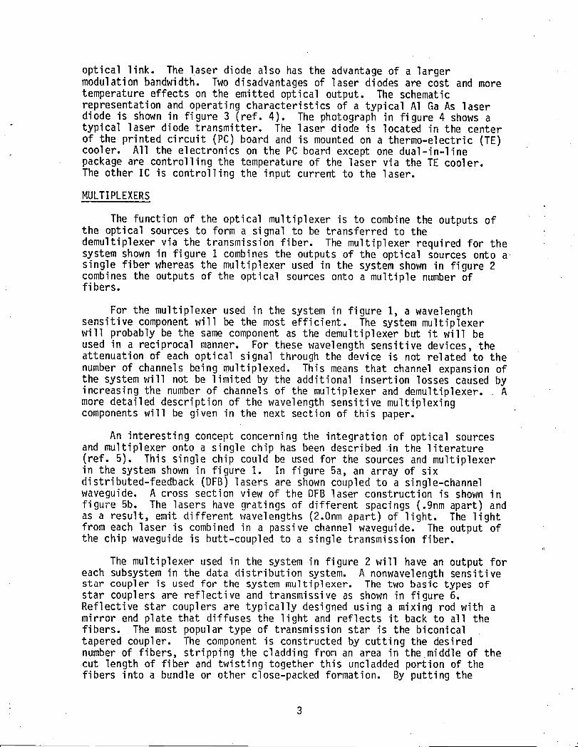
optical link. The laser diode also has the advantage of a largermodulation bandwidth. Two disadvantages of laser diodes are cost and moretemperature effects on the emitted optical output. The schematicrepresentation and operating characteristics of a typical A1 Ga As laserdiode is shown in figure 3 (ref. 4). The photograph in figure 4 shows atypical laser diode transmitter. The laser diode is located in the centerof the printed circuit (PC) board and is mounted on a thermo-electric (TE)cooler. All the electronics on the PC board except one dual-in-linepackage are controlling the temperature of the laser via the TE cooler.The other IC is controlling the input current to the laser.
MULTIPLEXERS
The function of the optical multiplexer is to combine the outputs ofthe optical sources to form a signal to be transferred to thedemultiplexer via the transmission fiber. The multiplexer required for thesystem shown in figure 1 combines the outputs of the optical sources onto asingle fiber whereas the multiplexer used in the system shown in figure 2combines the outputs of the optical sources onto a multiple number offibers.
For the multiplexer used in the system in figure 1, a wavelengthsensitive component will be the most efficient. The system multiplexerwill probably be the same component as the demultiplexer but it will beused in a reciprocal manner. For these wavelength sensitive devices, theattenuation of each optical signal through the device is not related to thenumber of channels being multiplexed. This means that channel expansion ofthe system will not be limited by the additional insertion losses caused byincreasing the number of channels of the multiplexer and demultiplexer. Amore detailed description of the wavelength sensitive multiplexingcomponents will be given in the next section of this paper.
An interesting concept concerning the integration of optical sourcesand multiplexer onto a single chip has been described in the literature(ref. 5). This single chip could be used for the sources and multiplexerin the system shown in figure I. In figure 5a, an array of sixdistributed-feedback (DFB) lasers are shown coupled to a single-channelwaveguide. A cross section view of the DFB laser construction is shown infigure 5b. The lasers have gratings of different spacings (.9nm apart) andas a result, emit different wavelengths (2.0nm apart) of light. The lightfrom each laser is combined in a passive channel waveguide. The output ofthe chip waveguide is butt-coupled to a single transmission fiber.
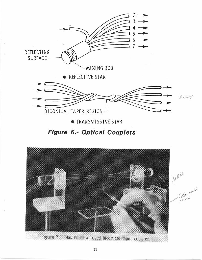
The multiplexer used in the system in figure 2 will have an output foreach subsystem in the data distribution system. A nonwavelength sensitivestar coupler is used for the system multiplexer. The two basic types ofstar couplers are reflective and transmissive as shown in figure 6.Reflective star couplers are typically designed using a mixing rod with amirror end plate that diffuses the light and reflects it back to all thefibers. The most popular type of transmission star is the biconicaltapered coupler. The component is constructed by cutting the desirednumber of fibers, stripping the cladding from an area in themiddle of thecut length of fiber and twisting together this uncladded portion of thefibers into a bundle or other close-packed formation. By putting the

fibers under tension and subjecting them to a closely controlled heat, thefibers will soften and fuse together. By placing tension on the fibersduring this fusing process, a biconical tapered region will form (figure7). As light from the optical sources travels through the input fibers tothis fused region, the taper will keep the light trapped in this fusedportion of the fiber° If the device is constructed properly, the inputlight will be equally distributed to the output fibers° The throughputattenuation of an optical star coupler is equal to the reciprocal of thenumber of outputs of the star plus the excess loss in the coupler. Thisexcess loss is typically 2db. There are many other ways of mechanizingstar couplers such as the use of lenses and optical planar devices but anindepth discussion of this subject is beyond the scope of this tutorialpaper. Most of the devices require more elaborate fabrication techniqueswith little performance improvement.
DEMULTIPLEXER
The function of the demultiplexer is to separate the multiplexedoptical signal into the individual wavelength components. Thedemultiplexer is the major developments component in a WDMsystem.
The success of a WDMsystem is directly proportional to the crosstalklevel and insertion loss associated with the demultiplexer. Thedemultiplexer must separate each wavelength despite the modal, linear, andangular dispersion of the transmission fiber waveguide supply in thedemultiplexer with its signal. For the transmission system to operate witha 10-9 bit error rate, the crosstalk levels between the outputs should beless than 30db. The spectral width of each output should be narrow so noinfringement of light occurs on the spacial region of the other outputs.This infringement causes interchannel crosstalk. The insertion loss .......requirements of the demultiplexer is dependent on the WDMoverall systemdesign but with sources and detectors available today, allowable lossesbetween transmitters and receivers of 50db or more are possible (ref. 6).
The primary components used for performing the demultiplexing are(ref. 7) prisms, filters, and gratings. In this section of the paper, ageneral description of the principle of operation for each demultiplexingcomponent will be given along with general performance comments_
Prisms
A functional schematic of a typical prism demultiplexer is shown infigure 8. A prism demultiplexer is classified as an angular dispersingdevice (ref. 8)° The radiation from the input fiber is collimated by alens and passed through the prism which disperses the radiation accordingto wavelength. The separated wavelengths are focused on the output fibersby a second lens. Prism demultiplexers are expensive to produce becausethe design requires two lenses and an expensive, high-quality prism. Aprism demultiplexer is also bulky. Few prism demultiplexers have beenbuilt because of high cost and difficulty of miniaturization and therefore,performance characteristics are sparse. In addition, precise mounting ofthe input and output fibers, both lenses, andthe prism element isrequired. "
4

Filters
In many WDM systems,filtersare used to help improvethe signal tonoise ratio of the detected signals,but few are used as the wavelengthdiscriminatingdevice. In general,there are two classesof opticalfilters,the bandpassfilter or interferencefilter and the high or lowpass filter or the dichroicfilter. For the interferencefilter there areessentiallytwo types: (1) absorbtionfilters,and (2) dielectric(non-absorbing)filters. The absorbtionfiltersare generallymade of gelatincontainingvariousorganicand inorganicdyes° The filtersare sensitiveto temperature,humidity,and prolongedexposureto light° The filters arequite broadband(typicallO0.Onm)With a transmittanceof approximately50percent. Becauseabsorbtionfiltersare broadbandand environmentallysensitive,they are not viable for use in WDM systems (ref.9). Thedielectricfiltersare usuallymade of multilayersof differentrefractiveindex dielectricmaterials. These filtersare sealed againsthumidityeffectsand are quite flexable. The filtershave bandwidthsbetween o5nmto 50.Onm and a transmittanceof 50 percentor greater. The dielectricfiltersare very sensitiveto the angle and collimationof the enteringlight.
A dichroicfilter is an opticalcomponentthat discriminateswavelengthsby transmittingcertainwavelengthswhile reflectingenergy ofhigheror lowerwavelengths. These filtersare usuallyused at an angle ofincidenceof 450 with the light beam. The longerwavelengthsof light arepassedthrough_he filtervlhilethe shorterwavelengthsof light arereflectedat 90u to the passed beam. Temperaturechangeshave about thesame reaction,approximately0.8 percentto 2.2 percentper 100 degreesC,on dichreicfiltersas on dietectricfilters.
Since a properlydesigned filterwill only select a single wavelengthout of a compositesignal,an N channelWDM systemwould requireat least_I-1filtersand N+I separatecollimators. The insertionloss of a filtertype demultiplexerusing filters_,lillbe proportionalto the number ofchannelsin the WDM system. The more channelsthe more a given wavelengthmay be attenuatedas it passes throughthe demultiplexer. Also, the sizeof the demultiplexeris proportionalto the number of wavelengthsbeingseparated° The attractivefeaturesof interferencefiltersare ease ofproduction,small size capability,and low cost.
Shown in figure9 is a simplifiedschematicof a demultiplexerusinginterferencefilters° A four wavelengthsystem (ref. 10) with 20 to 30dbisolationbetweenchannels and 8 to 11db of insertionloss has been builtand tested. A simplifiedschematicof a demultiplexerusing dichroicfilters is shown in figure 10. A full duplexbidirectionallink has beenbuilt and tested using dichroic filters(ref. 11). The two wavelengthsystemhad approximate12db attenuationvlith-30dbto -40db crosstalk.There are other systemsfor which each channelhasequal path lengths(ref. 9) and for an eight wavelengthsystem each channelpassesthroughonly three filters° Other demultiplexershave been tried using dichroicfilters° One type uses fiberscut and polishedat 45 degreesto theirlongitudinalaxis. The filters are sandwichedbetweenthe fibers° Bysendingtwo wavelengthsignalsdown the fiber,one will pass throughthefilterwhile the other will be reflected900 into a second fiber (ref.11).

Very little experimental data have been published on demultiplexers usingdichroic filters.
Other demultiplexer approaches have been described in the literature(ref. 8) using multiple-grating filters. This approach has the advantageof eliminating all except one collimating lens and a single output focusinglens, thereby simplifying the packaging of the demultiplexer. Because ofthe difficulty of producing a photosensitive material suitable for makingthese devices, they are not realiable at this time but such a materialmight be developed in the future.
Diffraction Gratings
A diffraction grating operates in a similar manner as a prism in thatit spreads out a light beam into its component wavelengths. This process,which is called dispersion, is performed in parallel with prisms anddiffraction grating demultiplexers, and in series with filterdemultiplexers. Any device which is equivalent in its action to a numberof parallel equidistance slits of the same width is called a diffractiongrating. There are two types of diffraction gratings; the transmissiongrating and reflection grating. All of the demultiplexers described inthis section of the paper use the reflection type of grating. A reflectiongrating can be made by ruling parallel lines on a polished plate. Thesurface between the ruled lines is capable of reflecting light while theruled lines will not reflect light. The surface reflecting the light ineffect form reflecting slits. The efficiency of a diffraction grating canbe improved by blazing the grooves° To blaze the grooves, each reflectingsurface is constructed at anangle proportional to the wavelength at whichthe diffraction grating is designed to disperse. Blazed reflective ........
gratings can be 75 percent or more efficient. Blazed gratings are iconstructed by ruling with a diamond point, chemical etching, photoetching, or ion milling. I
To use a diffraction grating as the wavelength separating element in ademultiplexer, the light before diffraction must be collimated and afterdiffraction must be focused on each output fiber° The methods ofperforming this collimation and focusing form the major differences in thedemultiplexer designs. Demultiplexers which use lenses,Graded-Refractive-lndex (GRIN) rods, and planar waveguides will bedescribed.
The optical demultiplexer described in reference 12 uses twoconventional lenses as the collimator and focuses and a blazed reflectivediffration grating as the wavelength sensitive element° The demultiplexeris mounted in a Littrow configuration as shown in figure 11. Radiation ofwavelengths _1,_2,_3,.o._n enters the device through the input fiberand is collimated by the lenses. The collimated light strikes thereflection diffraction grating and is dispersed according to the wavelengthcomponents of the input. The lens focuses the diffraction reflected beamof each wavelength on the receiving output fibers° A system of fivechannels with a wavelength spacing of 20.Onm in the 800nm region has beenconstructed and tested (ref. 12). The insertion loss was about 1.7db ineach channel, and crosstalk was less than -30db. The opticaldemultiplexers described in references 13 and 14 use a GRIN rod lens (also
I
6
I J

known as selfoc lens) for the collimating component. A GRIN rod lensconsists of a cylinder of dielectric material with a refractive-indexdistribution that has a maximumat the rod axis and decreases approximatelyas the order of the square of the radial distance from the rod axis. In aGRIN rod lens, light rays follow approximately sinusoidal paths with nearlyconstant periods (L)o In the demultiplexer, the GRIN rod lens is cut tolength L/4. The lenses are used to convert the small-diameter,large-numerical-aperture beams from the input fibers of the demultiplexerinto a large-diameter collimated output beam. An excellent description ofGRIN rod lenses is given in reference 13. A schematic of a demultiplexerwhich uses a GRIN rod lens is shown in figure 12. As the demultiplexerreceives the combined light radiation ( Z1,_2,_3, .... _n) from the inputfiber the GRIN rod lens collimates the beam. The collimated beamstrikesthe reflection diffraction grating and is separated into its wavelengthcomponents. The reflected beams then reenter the GRIN rod lens whichfocuses each wavelength to a distinct position on the face of the rod. Theoutput fibers Of the demultiplexer are butted to the rod face where theoutput rays of the demultiplexer are focused. The space between the lensand the grating can be filled with a wedge-shaped dielectric spacer so thatthe entire device can be cemented together into a stable solid assembly.Experimental models of demultiplexers using the GRIN rod lens have beenbuilt to be about the size of a paper clip. A twelve-channel demultiplexerhas also been reported (reference 14) which has an average channel spacingof 17.0nm. The insertion loss averaged approximately 3db and the averageadjacent channel crossta!k was -32db.
A planar Rowland spectrometer for an optical wavelength demultiplexerwas described and reported in the literature (refo 15). A schematic of theplanar Rowland demultiplexer is shown in figure 13. If, in a Row!andspectrometer, a concave grating of radius of curvature R is placedtangentially to a circle of diameter R such that the grating center liesupon the circumference, then the spectrum of an illuminated point lyingupon the circle will be focused upon this circle (known as a Rowlandcircle). The Rowland geometry is unique in that, in the absence ofaberration, the optics of the device produce a one-to-one image of theinput spot at the output plane. _ If a planar waveguide is incorporated inthe structure no external collimating or focusing devices between theinput and output fibers are required.
The demultiplexer is constructed by epoxying a thin optical waveguide(approximately .075mm) between two support microscope slides. To the endface of the device, which has a radius of curvature R, a reflectiondiffraction grating is attached. At the front face of the structure, whichis cut to radius R/2, the input and output fibers are butt coupled to theplanar waveguide. The input beamto the demultiplexer, consisting of thewavelength components (_i,_ 2,_ 3, .... _n), enters the planar waveguidefrom the input fiber. The light travels through the planar waveguide whereit strikes the blazed reflective diffraction grating at the end face of thestructure. The beam is separated into its wavelength components where eachcomponent is reflected towards the front of the structure. Because of theRowland geometry, each wavelength is focused to a different spot along theFront face. For each wavelength position, there will be a fiber to collectthe output signal. A four-channel device has been constructed and testedwith lOoOnmseparation of wavelengths. The cross talk measured was -18db
o.
and typical insertion loss from input fiber to output fiber wasapproximately -9dbo More than half of the insertion loss was due to thepoor diffraction grating efficiency (5db). A demultiplexer using theRowland geometry similar to the GRIN rod lens device can be cementedtogether into a stable solid _ssembly.
Optical Detectors
None of the WDMsystems described in this paper require wavelengthsensitive optical detectors. Depending on the particular WDMsystemdesign, a decision will have to be made on whether to use a PIN photodiodeor an Avalance photodiode. The avalance photodiode is a more sensitivedetector but it requires a I00 to 400 volt bias. A detailed discussion ofoptical detection is beyond the scope of this paper.
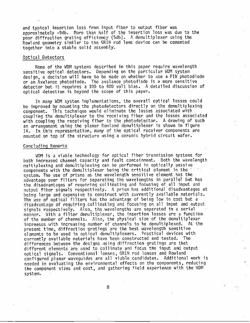
In many WDMsystem implementations, the overall optical losses couldbe improved by mounting the photodetectors directly on the demultiplexingcomponent. This technique would eliminate the losses associated withcoupling the demultiplexer to the receiving fiber and the losses associatedwith coupling the receiving fiber to the photodetector. A drawing of suchan arrangement using the planar Rowland demultipiexer is shown in figure14. In this representation, many of the optical receiver components aremounted on top of the structure using a ceramic hybrid circuit wafer.
Concluding Remarks
WDMis a viable technology for optical fiber tranmission systems forboth increased channel capacity and fault containment. Both the wavelengthmultiplexing and demultiplexing can be performed in optically passivecomponents with the demultiplexer being the critical element in the ........system. The use of prisms as the wavelength sensitive element has theadvantage over filters for separating the wavelengths in parallel but hasthe disadvantages of requiring collimating and focusing of all input andoutput fiber signals respectively. A prism has additional disadvantages atbeing large and expensive to construct with currently available materials.The use of optical filters has the advantage of being low in cost but adisadvantage of requiring collimating and focusing on all input and outputsignals respectively. Also, the wavelengths are separated in a serialmanner. With a filter demultiple×er, the insertion losses are a functionof the number of channels. Also, the physical size of the demultiplexerincreases with increasing number of channels to he demultiplexedo At thepresent time, diffraction gratings are the best wavelength sensitiveelements to be used in optical demultiplexers. Practical devices withcurrently available materials have been constructed and tested: Thedifferences between the designs using diffraction gratings are thatdifferent elements are used to collimate and focus the input and outputoptical signals. Conventional lenses, GRIN rod lenses and Rowlandconfigured planar waveguides are all viable candidates. Additional work isneeded in evaluating the environmental effects on the components, reducingthe component sizes and cost, and gathering field experience with the WDMsystem.
...

REFERENCES
1. Metcalf, B. D.; and Providakes, J. F.: High-Capacity WavelengthDemultiplexer with a Large-Diameter GRIN-Rod Lens. Applied Optics,vol. 21, no. 5, Mar.l, 1982, pp. 794-796.
2. Spencer, J. Larry; and Himka, Roger L.: Description and Planned Useof a Data Distribtuion Evaluation System for Fiber Optic Data Buses.Paper to be presented at the National Aerospace and ElectronicsConference, Dayton, Ohio, May 18-20, 1982.
3. Bolz, Don; and Herskowitz, Gerald J.: Components for OpticalCommunications Systems_ A Review. Proceedings of the IEEE, vol. 68,no. 6, June 1980, pp. 689-731.
4. Ladany, I; and Hammer, J. M.: Single-Mode Laser Studies: (I) Designand Performance of a Fixed-Wavelength Laser Source and (II) Couplingof Lasers to Thin-Film Optical Waveguides. NASACR-3341, 1980.
5. Aiki, K.; Nakamura; and Umeda, J.: Frequency Multiplexing LightSources with Monolithically Integrated Distributed Feedback DiodeLasers. Applied Physics Letters, vol. 29, no. 8, Oct. 1976,pp. 506-508.
6. Barnoski, Michael K., ed.: Fundamentals of Optical FiberCommunications. Chapter 6. Academic Press, Inc., 1976, pp. 183-201.
7. Rickard, Eric: Wavelength Division Multiplexing: Overview of theState of the Art. RADC-TR-81-47, Mar. 1981.
8. Tomlinson, W. J.: Wavelength Multiplexing in Multimode OpticalFibers. Applied Optics, vol. 16, no. 8, Aug. 1977, pp. 2180-2194.
9. Stigliani, Daniel J., Jr.; Hanna, D. W.; and Lynch, R. J.: WavelengthDivision Multiplexing in Light Interface Technology. IBM Report,NR 71-531-001, Mar. 18, 1971.
10. Hendricks, Herbert D.; Spencer, J. Larry; and Magee, Carl J.: FiberOptics Wavelength Division Multiplexing for Data Systems. FutureConnections-NASA, vol. I, nor 2, Nov° 1981, ppo 9-12.
II. Nelson, A. R.; Gasparian, G. A.; and Beckel, G. W.: BidirectionalCoupler for Full Duplex Transmission on a Single Fiber.CODACOM-77-1798-F,ITT Electro-Optical Products Div., Aug. 1979.
12. Aoyama, Koh-ichi; and Minowa, Jun-ichrio: Low-Loss OpticalDemultiplexer for WDMSystems in the 0.8- m Wavelength Region.Applied Optics, vol. 18, no. 16., Aug° 15, 1979, pp. 2834-2836.
13. Tomlinson, W. J.: Application of GRIN-Rod Lenses in Optical FiberCommunication Systems° Applied Optics, vol. 19, no. 7, Apr. I, 1980,ppo 1127-1138.
14. Yen, H. W.; Friedrick, H. R.; and Morrison, R.J.: Planar RowlandSpectrometer for Fiber-Optic Wavelength Demultiplexing. OpticsLetters, vol. 6, no. 12, Dec. 1981, pp. 639-641.
9

sou.c,s o,,,c,o,sCHANNELII ;_1 _,, }'I_CHANNEL 1
I _. TRANSMISSION• ;_--//
CHANNEL21 x2__, FIBER z_CHANNEL 2
•.•
Figure1.- WDMsystemfor increasedchannelcapacity.
SUBSYSTEM #1 SUBSYSTEM "*2
Tra nsmi tter Tra nsmi tter
_ [ .kl _2 l
I'i Detectors Detectors_2 IIIIIIF11"11'lr -
I r/i " ? DemuxiT " I
\ .,yb_' [ Demux ]
Multiplexer
>,i >,2
Demux Demux
A
;ors Detectors
I x4 x3.ITransmitter Transmitter
SUBSYSTEM e4 SUBSYSTEM _3
Figure2.- WDMsystemfor fault isolation.
10/,:,

#
11 //

COUPLER7DFBLASER--_ //--WAVEGUIDE OPTICAL
)_> }'I'}'2....
(a)Schematic
JV
,J
_ DFBLASER _i= WAVEGUIDE_< Zn-DIFFUSION
UNDOPED-GagAI1As
p-Ga93AIo7AS-_p-Ga7AI3As
p-Ga8AI2Asp_OaAs___ n-Oa7Al3As =:€>p-Ga7AI3As(ACTIVE)
n-GaAsSUBSTRATE l
! I
5pm(b) Cross-sectionalview
Figure5.- Arrayof 6DFBlasers.
12
MIXINGROD
• REFLECTIVESTAR
• TRANSMISSIVESTAR
Figure 6.. Optical Couplers
13
I

PRISMINPUT LENS LENSFIBER OUTPUT "_
FIBERS
Figure8.- Prismdemultiplexer
2 /-OUTPUT 3
/-FI LTER_ "INPUT , ,-- _ , _-LENS
_1'_2'_3' _4 _ 0_"1_ _ " ,_'-"J_U 0 (1"-'-_ ;k4
FILTER_I _ i SPLITTERS_ FIBERo_ LENS
OUTPUT_:[FIBER
Figure9.- Demultiplexerusing interferencefilters.
14

TRANSMISSION _ LENS GRATING• /-
7.50
OUTPUTFIBERS
Figure11.- Demultiplexerusingconventionallensesin a Littrowmount.
15

REFLECTIONGRATI
" GLASSWEDGE
Xl° X2' X3.... UIFIBER
Figure12.- Demultiplexerusinga GRINrodlens.
WAVEGUIDE \ END
INPUT FRONTFIBERS FA( RI2
;k], ;_2'_3' ;_4 R
_v OUTPUT X2 \_ j//FIBERS -- --- /
FLEXIBLEGRATING
j,
s
tJ'
WAVEGUIDELAYER
(COVERGLASS)GLASSSLIDES
Figure13.- Demultiplexerusinga planarRowlandstructure.
16
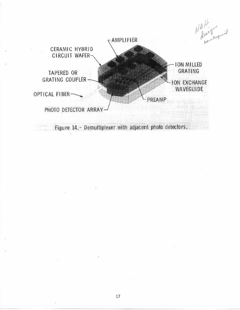
CERAMIC HYBR!D
CIRCUITWAFER-x,\
" IONM!LLEDTAPEREDOR GRATING
GRATINGCOUPLER E×CHANGEWAVEGUIDE
OPTICALF!BER----._
PHOTODETECTORARRAY
Figure 14.- Demu!tip!exer with:adj_.a_ent:_pholo:det_::I0.rs_::
17

"i. Report No. 2. Government Accession No. 3. Re_ipient's Catalog No.
NASATM 844834. Title and Subtitle 5. Report Date
MULTIMODEFIBER OPTIC WAVELENGTHDIVISION MULTIPLEXING .April 19826. Performing Organization Code
7. Author(s) 8. Performing Organization Report No. -
a. Larry Spencer 505-34-43-04'10. Work Unit No.
9. Performing Organization Name and Address
Langley Research Center 11.Contractor Grant No.National Aeronautics and Space AdministrationHampton, Virginia 23665
"13. Type of Report and Period Covered
12. Sponsoring Agency Name and Address Technical MemorandumNational Aeronautics and Space Administration "14.Sponsoring Agency Code-
Washington, DC 20546
15. Supplementary Notes "-
16. Abstract
Optical wavelength division multiplexing (WDM)systems, with signals transmittedon different wavelengths through a single optical fiber, can have increasedbandwidth and fault isolation properties over single wavelength optical systems.This paper considers two WDMsystem designs that might be used with multimodefibers and gives a general description of the components which could be used toimplement the system. The components described are sources, multiplexers, de-multiplexers, and detectors. Emphasis is given to the demultiplexer techniquewhich is the major developmental component in the WDMsystem.
17, Key Words (Sugg_ted by Author(s)) i8. Distribution Statement
Multiplexing Unclassified - unlimitedWavelength multiplexing
Wavelength division multiplexing Subject Category 33 62Fiber opticData distribution
., . ,,
19, S_urity _a_if. (of this reportl 20. S_urity Classif. (of this _ge) 21. No. of Pa_s 22. Dice
Uncl assi fi ed Uncl assi fi ed 18 A02
,-3os ForsalebytheNationalTechnicalInformationService,Springfield,Virginia22161


i 3 1176 00504 1471