muhammad saiful bin mustafa - institutional repositoryumpir.ump.edu.my/2872/1/cd5905.pdf ·...
TRANSCRIPT

TURBULENT FLAME SPEED IN SPARK IGNITION ENGINE COMBUSTION PROCESS USING COMPUTATIONAL
FLUID DYNAMICS (CFD)
MUHAMMAD SAIFUL BIN MUSTAFA
BACHELOR OF MECHANICAL ENGINEERING UNIVERSITI MALAYSIA PAHANG

vi
ABSTRACT
This thesis deals with the numerical study about turbulent flame speed in spark ignition engine during the combustion process using Computational Fluid Dynamics (CFD). The objective for this project is to analyze the behavior and predicted trend of turbulent flame speed that occurs during the combustion process at single operating point for 2000 revolution per minute (rpm) engine speed. Turbulent flame speed is the important parameter that controls the cylinder pressure during combustion process in spark ignition (SI) engine. This thesis described on technique to tackle the objective starting from engine modeling until finish of the project. The analysis is focusing on spark ignition combustion process of the baseline engine design, Mitsubishi magma 4G15. Engine was modeled using Solid work software and then analysis using CFD. The engine model was design in 3-Dimensional (3D). The speed of engine is fixed at single operating point at 2000 rpm. For numerical modeling approach, k-epsilon (k-�) standard turbulence model was selected. The iteration number is set at 1500 iteration per time step. The accuracy test is based on cylinder pressure and the simulation data is validated with experiment data. It is known that an increase in turbulent flame speed increases the cylinder mixtures that have been burned. Thus increase the cylinder temperature and relates with the increase in cylinder pressure during the combustion process.

vii
ABSTRAK
Tesis ini membincangkan kajian berangka tentang halaju nyalaan gelora di dalam enjin cucuhan bunga api semasa proses pembakaran menggunakan Perkomputeran Dinamik Bendalir. Tujuan utama projek ini adalah untuk menganalisa perilaku dan jangkaan corak halaju nyalaan gelora yang terjadi semasa proses pembakaran pada satu titik operasi untuk kelajuan enjin 2000 revolusi per minit (rpm). Halaju nyalaan gelora adalah parameter penting yang mengawal tekanan silinder semasa proses pembakaran dalam enjin cucuhan bunga api. Tesis ini menjelaskan tentang cara untuk mencapai tujuan bermula daripada membuat model sehingga selesai projek. Analisa memfokuskan pada proses pembakaran ke atas enjin cucuhan bunga api untuk reka bentuk enjin rujukan, Mitsubishi Magma 4G15. Enjin dimodel menggunakan perisian Solid work dan analisa menggunakan Perkomputeran Dinamik Bendalir. Model enjin telah direka bentuk dalam 3-dimensi (3D). Kelajuan enjin telah ditetapkan pada titik operasi pada 2000 rpm. Untuk pendekatan kajian berangka, k-epsilon (k-�) asas model gelora telah dipilih. Bilangan lelaran ditetapkan pada 1500 sela setiap masa. Ketepatan ujian adalah berdasarkan pada tekanan silinder dan data simulasi disahkan dengan data eksperimen. Adalah diketahui bahawa peningkatan dalam halaju nyalaan gelora meningkatkan jumlah campuran silinder yang telah dibakar. Ini meningkatkan suhu silinder dan berkait dengan peningkatan dalam tekanan silinder semasa proses pembakaran.

viii
TABLE OF CONTENTS
Page
SUPERVISOR’S DECLARATION ii
STUDENT’S DECLARATION iii
DEDICATION iv
ACKNOWLEDGEMENT v
ABSTRACT vi
ABSTRAK vii
TABLE OF CONTENTS viii
LIST OF TABLES xi
LIST OF FIGURES xii
LIST OF SYMBOLS xiii
LIST OF ABBREVIATIONS xv
CHAPTER 1 INTRODUCTION
1.1 Introduction 1
1.2 Problem statement 2
1.3 Objective 3
1.4 Scopes 3
1.5
1.6
Flow chart
Organization of thesis
4
5
CHAPTER 2 LITERATURE REVIEW
2.1 Introduction 6
2.2 Internal combustion engine 6
2.3 Spark ignition engine (SI engine) 7
2.4 Combustion in SI engine 7
2.5 Turbulence flow 9
2.6
2.7
Characterization of flames
Flame structure
10
11

ix
2.8
2.9
2.10
Laminar flame speed
Turbulent flame speed
Summary
12
14
17
CHAPTER 3 METHODOLOGY
3.1 Introduction 18
3.2 Baseline engine specification 18
3.3 Engine structural modeling 19
3.4 Grid generation and domain creation 20
3.5
3.6
3.7
3.8
3.9
3.10
Governing equation for computational fluid dynamics
3.5.1 Mass conservation equation
3.5.2 Momentum conservation equation
3.5.3 Energy conservation equation
Premixed combustion theory
3.6.1 Progress variable
3.6.2 Turbulent flame speed model
Turbulence specification
3.7.1 k-ε-standard
Solution setup
3.8.1 Initial condition
3.8.2 Premixed mixture properties
Validation method
Limitation of study
21
21
22
23
24
24
25
26
26
27
27
28
30
30
CHAPTER 4 RESULTS AND DISCUSSION
4.1 Introduction 31
4.2
4.3
4.4
4.5
Cylinder combustion pressure
Turbulent flame speed
Progress variable
4.4.1 Flame propagates during combustion process
Summary
31
33
37
38
39

x
CHAPTER 5 CONCLUSSION AND RECOMMENDATION
5.1
5.2
Conclusion
Recommendation
40
41
REFERENCES
42

xi
LIST OF TABLES
Table No.
Title Page
2.1
Combustion process of SI engines 8
2.2
Turbulence model characteristics 9
2.3
Parameter for ∅�, �� and �∅ 13
2.4
Important factors for mean reaction rate of cylinder mixture 15
3.1
Engine specification Mitsubishi Magma 4G15 18
3.2
Initial condition at 2000 rpm 27
3.3
Input data for premix-mixture properties at 2000 rpm 29

xii
LIST OF FIGURES
Figure No.
Title Page
1.1
Project flow chart 4
2.1
Cylinder pressure in the combustion chamber of an SI engine 8
2.2
Laminar burning velocity for several fuels at 1 atm and 300 K 13
2.3
Flame speed in the combustion chamber of an SI engine as a
function of the air-fuel ratio for gasoline-type fuels
16
2.4
Turbulent flame speed against mass fraction burn 16
3.1
Right view and isometric view of the engine model 19
3.2
Engine meshing 20
4.1
Comparison between experimental and simulation data on cylinder
pressure
32
4.2
Turbulent flame speed for simulation 2000 rpm engine speed 34
4.3
Relationship between turbulent flame speed and cylinder mixture 35
4.4
Turbulent flame speed against mass fraction burn 36
4.5
Progress variable for simulation 2000 rpm engine speed 37
4.6 Visual of flame propagates through combustion chamber during
combustion process in term of progress variable
38

1
CHAPTER 1
INTRODUCTION
1.1 INTRODUCTION
Internal combustion engine is an engine in which the combustion takes place
internally. It is combustion of a fuel occurs with an oxidizer, usually air in a
combustion chamber (Pulkrabek, 1997). The combustion process in spark ignition
engines plays a key role in the conversion of fuel energy into mechanical energy
(Trautwein, 1990). The intake and compression stroke is one of the most important
processes because it influences the pattern of air flow structure coming inside the
cylinder. As the result of the high velocity inside the internal combustion engine
during operation, all flow in-cylinder is typically turbulent (Kurniawan, 2007). After
ignition at the spark plug, the mixture of fuel and air starts to burn and continues
burning until consuming the whole of the fuel of the charge in the cylinder. The
burning rate of premixed turbulent flames depends strongly on the parameters of a
turbulent flow. When turbulent is sufficiently strong, then the burning rate is
controlled mainly by the turbulent parameters, rather than by thermo-chemical
velocity of a planar laminar flame front (Akkerman, 2009). The burning time may
vary from one engine to another and each has certain burning rate. Many
experiments show that the burning rate depends mostly on the combustion chamber
shape and the position of the spark plug (Kodah, 1999).
The simulation of the physical process in engine combustion chamber has
found increasing interest during recent years. To validate new design concept
through experimental work takes a long time and high cost especially during
prototype developing stage. The computer simulation techniques are useful

2
alternative way, provided that the simulation model is accurate and fast enough to
execute. Computer simulations of internal combustion engine cycle are desirable
because of the aid that they provide in design studies, in predicting trends, in serving
as investigations tools, in giving more data than are normally accessible from
experiments, and in helping to understand the complex process that occur inside
combustion chamber (Hosseini, 2008). During the last decades, computational fluid
dynamics has significantly contributed to the engine development process (Hascher,
2000). It is based on the solution of the fluid dynamic governing equations which is
contains of mass, momentum, species conservation equation and energy. Additional
equation for turbulence, heat transfer, spark ignition and reaction rate also required to
capture all the associated combustion phenomena (Fadzil, 2008).
1.2 PROBLEM STATEMENT
It is known that combustion duration is an important parameter in spark
ignition engine and mainly is controlled by turbulent flame speed. It is expected that
the turbulent flame speed influence the cylinder pressure in combustion process.
Thus, further analysis for turbulent flame speed in combustion process is required to
identify the relation by using CFD method.

3
1.3 OBJECTIVE
The objective of this project is to analyze the behavior and predicted trend of
turbulent flame speed at single operating point for 2000 rpm engine speed during
combustion process.
1.4 SCOPES
In this study, the analysis of turbulent flame speed in spark ignition engine
combustion process is carried out in the framework of turbulent flame speed closure
model of Zimont using CFD. Single operating point at 2000 rpm is simulated in CFD
in order to study the predicted trend and behavior of turbulent flame speed during the
combustion process.

4
Yes
No
1.5 FLOW CHART
The flow chart of the overall procedure of the study is shown in Figure 1.1:
Figure 1.1: Project flow chart
Validate
Turbulent flame speed in spark ignition engine combustion process
Develop 3D engine model using Solid work
Engine meshing using ANSYS
Computational Fluid Dynamics using ANSYS
Result Analysis and writing
Thesis Documentation
Start

5
1.6 ORGANIZATION OF THESIS
This thesis consists of five main chapters in order to acquire the main
objective of the study related to turbulent flame speed in SI engine combustion
process. The chapters are introduction, literature review, methodology, result and
discussion and lastly conclusion and recommendation. Chapter 1 has briefly
discussed about the introduction, problem statement, scopes of study, and also the
objective of the project. Chapter 2 is literatures that related to the study and become
basics of study framework. Chapter 3 presents the development of 3D model,
generation of computational model and also data build in for combustion process
using CFD. Chapter 4 addresses the validation of the simulated results against
experimental result of the cylinder pressure and how turbulent flame speed
influenced during combustion process. Chapter 5 presents the important findings of
the study and recommendation for future study.

6
CHAPTER 2
LITERATURE REVIEW
2.1 INTRODUCTION
This chapter deals with definition of SI engine and characteristics of
turbulence flow. Then this chapter continues with the importance of the study about
turbulence for in-cylinder flow. Lastly, discussion continues with the characterization
of flames, flame structure, laminar and turbulent flame speed.
2.2 INTERNAL COMBUSTION ENGINE
Internal combustion engine is the production of mechanical power from the
chemical energy that contained in the fuel. In internal combustion engines, energy is
released by burning or oxidizing the fuel inside the engine. It depends on the
exothermic chemical process of combustion, which is a process or reaction that
release energy usually in the form of heat, but also in the form of light (spark, flame
or explosion), electricity or sound. It consists of four consecutive process which is
intake, compression, expansion (including combustion) and exhaust. The work
transfers which provide the desired power output occur directly between working
fluids and the mechanical component of the engine (Heywood, 1998).

7
2.3 SPARK IGNITION ENGINE (SI ENGINE)
An SI engine starts the combustion process in each cycle by use of a spark
plug. The air and fuel are usually mixed together using carburetors or fuel-injection
system in the intake system prior to entry to the engine cylinder. At the combustion
chamber the spark plug gives a high-voltage electrical discharge between two
electrodes which ignites the air-fuel mixture that is surrounding the plug. During
intake, the inducted fuel and air mix in the cylinder with the residual burned gases
remaining from the previous cycle. After the intake valve close, the cylinder contents
are compressed above atmospheric pressure and temperature as the cylinder volume
is reduced. Between 10 and 40 crank angle degree (0CA) before top dead centre
(TDC) an electrical discharged across the spark plug starts the combustion process.
This process is then repeated for a cycle of periods during the engine process.
Combustion duration is an important parameter in operation of spark-ignition
engines and is controlled by turbulent flame speed and distribution of combustion
volume. Compact combustion chambers produce short combustion durations. A
turbulent flame develops from the spark discharge, propagates across the mixture of
air, fuel and residual gas in the cylinder, and extinguishes at the combustion chamber
wall. The duration of this burning process varies with engine design and operation.
2.4 COMBUSTION IN SI ENGINE
In an SI engine, combustion ideally consists of an exothermic subsonic flame
progressing through a premixed homogeneous air-fuel mixture. The spread of the
flame front is greatly increased by induced of turbulence, swirl and squish within the
cylinder. Combustion in an engine is a very complex process. The combustion
process of SI engines can be divided into three broad regions which are:

8
Table 2.1: Combustion process of SI engines
Stage Combustion process
1 Ignition and flame development
2 Flame propagation
3 Flame termination
Source: (pulkrabek, 1997)
The consumption of the first 5% or 10% of the fuel air mixture is generally
considered as the flame development. During this period, ignition occurs and the
combustion process starts, but very little pressure rise is noticeable and little or no
useful work is produced. The result of the flame propagation period of the
combustion process is when just about all useful work is produced in an engine
cycle. This is the period when the bulk of the fuel and air mass is burned. During this
time, the pressure in the cylinder is greatly increased. And this provides the force to
produced work in the expansion stroke. Flame termination is classified as the final
5% or 10% of the air-fuel mass which burns. During this time, pressure quickly
decreases and the combustion stops.
Figure 2.1: Cylinder pressure in the combustion chamber of an SI engine
Source: (pulkrabek, 1997)

9
2.5 TURBULENCE FLOW
All flow into, out of, and within engine cylinders are turbulence flows due to
the high velocities involved. As a result of turbulence, thermodynamics transfer rates
within an engine are increased by an order of magnitude. Heat transfer, evaporation,
mixing and combustion rates all increase (Pulkrabek, 1997). Certain properties could
be learned about turbulence using statistical methods. These introduce certain
correlation functions among flow variables. However it is impossible to determine
these correlations in advance (Sodja, 2007).
In nature, almost every fluid flow is turbulent. Whenever turbulence is
present in a certain flow it appears to be the dominant over all other flow
phenomena. When flow is turbulent, particles experience random fluctuations in
motion superimposed on their main bulk velocity. These fluctuations occur in all
directions, perpendicular to the flow and in the flow direction (Pulkrabek, 1997). The
characteristics of turbulence observed in nature are presented below:
Table 2.2: Turbulence model characteristics
Characteristic Definition
Unsteadiness Turbulence is always transient
Irregularity The flow is so irregular that we can neither follow nor
describe it completely
Three-dimensionally Even when the mean flow is one or two-dimensional, flow
fluctuations always have components in all three directions.
Dissipation The kinetic energy of turbulent motion is dissipated into heat
under the influence of viscosity
Diffusivity The rapid mixing of momentum, heat and mass is a typical
feature of turbulent flows.
Others Turbulence occurs at higher Reynolds number and it is not a
property of the particular itself.
Source: (Uygen, 2004)

10
There are many levels of turbulence within an engine. Large-scale of
turbulence occurs with eddies on the order of the size of the flow passage. For
example valve opening or the height of the clearance volume. On the other extreme,
the smallest scale turbulence is totally random and homogeneous, with no
directionality and controlled by viscous dissipation. There are all levels of turbulence
in between these extremes, with characteristics ranging from those of small scale
turbulence to those of large scale of turbulence.
Local flame speed depends on the turbulence immediately in front of the
flame. This turbulence is enhanced by the expansion of the cylinder gases during the
combustion process. The shape of the combustion chamber is important in generating
the maximum turbulence and increasing the desired rapid combustion. As speed is
increase, turbulence increase and this increase the rate of evaporation, mixing and
combustion. One result of this is that all engine speeds have about the same burn
angle. One phase of this process that not changed due to the increasing turbulence is
ignition delay. This is compensated for by advancing ignition spark timing which is
initiate the spark earlier as the engine speed increased (Pulkrabek, 1997).
2.6 CHARACTERIZATION OF FLAMES
Combustion of the fuel-air mixture inside the engine cylinder is one of the
processes that controls engine power, efficiency and emissions. In spark ignition
engines, the fuel is normally mixed with air in the engine intake system. Following
the compression of this fuel-air mixture is an electrical discharge initiates the
combustion process which then creates a flame. A flame that develops from the
“kernel” created by the spark discharge and propagates across the cylinder to the
combustion chamber walls (Heywood, 1988).
Flames are usually classified according to the following overall
characteristics. The first of these has to do with the composition of the reactants as
they enter the reaction zone. The flame is designated as premixed if the fuel and
oxidizer are essentially uniformly mixed together. The second means of classification
relates to the basic character of the gas flow through the reaction zone. In laminar

11
flow, mixing and transport are done by molecular process. Laminar flows only occur
at low Reynolds number. At high Reynolds number, turbulent flow is occurs. In
turbulent flows, mixing and transport are enhanced by the macroscopic relative
motion of eddies or lumps of fluid which are the characteristics feature of a turbulent
flow (Heywood, 1988).
2.7 FLAME STRUCTURE
The importance of the turbulence to the engine combustion process was
recognized long ago through experiments where the intake event, and the turbulence
it generates, was eliminated resulting with the rate of the flame propagation
decreased substantially. Mixture burning rate is strongly influenced by engine speed.
The duration of combustion in crank angle degrees only increases slowly with
increasing engine speed. Additionally, at a given engine speed, increasing in-cylinder
gas velocities increase the burning rate. Increasing engine speed and introducing
swirl both increase the levels of turbulence in the engine cylinder at the time of
combustion. With the increase in turbulence, this will increase the rate of
development and propagation of turbulent premixed engine flame. Laminar flames in
premixed fuel, air, residual gas mixtures are characterized by a laminar flame speed
�� and a laminar flame thickness ��, Turbulent flames are also characterized by the
root mean square velocity fluctuation, the turbulence intensity ú, and the various
length scale of the turbulent flow ahead of the flame (Heywood, 1988).

12
2.8 LAMINAR FLAME SPEED
Laminar burning velocity is an important intrinsic property of a combustible
fuel, air and burned gas mixture. This burning velocity is defined as the velocity,
relative to and normal to the flame front, with which unburned gas moves into the
front and is transformed to products under laminar flow conditions. The flame front
consists of two regions which is preheat zone and a reaction zone. In the preheat
zone, the temperature of the unburned mixture is raised mainly by heat conduction
from the reaction zone. The region between the temperature where exothermic
chemical reaction begins and the hot boundary at the downstream equilibrium burned
gas temperature is called the reaction zone. Laminar burning velocities at pressures
and temperatures typical of unburned mixture in engines are usually measured in
spherical closed vessels by propagating a laminar flame radially outward from the
vessel center. The laminar burning velocity is given by (Heywood, 1988):
�� = ���/��� � (2.1)
Where the mass burning rate is determined from the rate of pressure rise in
the vessel and �� is the flame area. Data at higher pressures and temperatures have
been fitted to a power law of the form (Heywood, 1988):
�� = ��,�(����)∝( �
��)� (2.2)
Where ��= 298 K and ��= 1 atm are the reference temperature and pressure,
and��,�,∝ and � are constant for a given fuel, equivalence ratio, and burned gas
diluents fraction. For propane, isooctane and methanol, these constants can be
represented by (Heywood, 1988):
∝= 2.18 − 0.8(∅ − 1) (2.3)
� = −0.16 + 0.22(∅ − 1) (2.4)
��,� = &� + &∅(∅ − ∅�)' (2.5)

∅� is the equivalence ratio at which
Values of ∅�,
Fuel
methanol
Propane
Isooctane
Gasoline
Figure 2.2: Laminar burning velocity for several fuels
is the equivalence ratio at which ��,� is a maximum with value
, &�, and &∅ are given in Table 2.3.
Table 2.3: parameters for ∅�, &� and &
∅( )(, *(/+ )∅1.11 36.9 -
1.08 34.2 -
1.13 26.3
1.21 30.5
Source: (Heywood, 1988)
Laminar burning velocity for several fuels at 1 atm and 300 K
Source: (Heywood, 1988)
13
is a maximum with value &�.
&∅
∅, *(/+
-140.5
-138.7
-84.7
-54.9
at 1 atm and 300 K

14
The presence of burned gas in the unburned cylinder charge due to residual
gases and any recycled exhaust gases causes a substantial reduction in the laminar
burning velocity. Any burned gas in the unburned mixture reduces the heating value
per unit mass of mixture, thus reduces the adiabatic flame temperature. It acts as
diluents. The proportional reduction in laminar burning velocity is essentially
independent of the unburned mixture equivalence ratio, pressure and temperature
over the range of interest in engines. The data are correlated by the relation
(Heywood, 1988):
���,-.� = ���,-. = 0��1 − 2.06,-./.00� (2.6)
,-. = the mole fraction of burned gas diluents.
2.9 TURBULENT FLAME SPEED
Due to their fundamental importance for premixed combustion theory,
turbulent flame speed was a subject of a large number of investigations for many
decades. Beginning with the classical work of Damko2 hler, turbulent flame speed by
analogy with laminar flames has been assumed to be a basic characteristic of
premixed turbulent combustion and has been the main focus of numerous
experimental and theoretical studies (Lipatnikov, 2002). The first stage of the
combustion is the ignition and flame development which is associated with burning
of 5-10% of the cylinder mixture. The process is nearly laminar in nature at least at
low to intermediate engine speed. There is only very small pressure and temperature
rise during this period due to low mixture burned and consequently low energy
released. Turbulent propagation flame is the next stage, where it is usually associated
with 90-95% of mass fraction burned. The reaction sheet flame propagating outward
in an approximately spherical manner. The thin reaction sheet flame is wrinkled by
the turbulence motion at scale smaller than the flame radius. Comparable and larger
scales of turbulence than the flame radius only distorted and convected the overall
flame shape (Fadzil, 2008).

15
The effect of turbulence increases the flame propagation speed and the value
is about 10 times faster than laminar flame front propagation. There are two
mechanisms induced by turbulence, which is the wrinkling and stretching effect on
the flame. By increasing the surface of thin reaction sheet within the turbulent flame
zone, the burning rate increase by the wrinkling effect. While the stretching effects,
which is produced by the wrinkling primarily, slowing down the burning rate by
slowing the molecular diffusive process within the reaction sheet (Heywood, 1988).
The mean reaction rate of the cylinder mixture is mostly governed by the three most
important factors that is:
Table 2.4: important factors for mean reaction rate of cylinder mixture
Factors Definition
Structure or geometry of the flame front Highly influenced by the geometrical
confinement of the flame.
Unburned mixture composition and state Related with thermo-chemical properties
Turbulent flame speed Govern the rate at which the flame front
propagates across the combustion
chamber
Source: (Fadzil, 2008)
In addition to the effects of turbulence, swirl and squish, the flame speed
depends on the type of fuel and the air-fuel ratio. Lean mixtures have slower flame
speeds. Rich mixtures have the fastest flame speeds, with the maximum for most
fuels occurring at an equivalence ratio near 1.2. Exhaust residual and recycled
exhaust gas slows the flame speed (Pulkrabek, 1997). As the flame propagates after
the spark ignites, the cylinder mixtures that have been burned also increased.
Turbulent flame speed is decrease as the flame front approaching the cylinder wall
and this is where all the cylinder mixture has been completely burned.

Figure 2.3: Flame speed in the combustion chamber o
the air-fue
Figure 2.4:
lame speed in the combustion chamber of an SI engine as a function of
fuel ratio for gasoline-type fuels
Source: (Pulkrabek, 1997)
Figure 2.4: Turbulent flame speed against mass fraction burn
Source: (Larusso, 1976)
16
f an SI engine as a function of
eed against mass fraction burn

17
Turbulent flame flames have a propagation velocity that depends on the
character of flow, as well as on mixture properties. Turbulent flame speed, St can be
defined as the velocity at which unburned mixture enters the flame zone in a
direction normal to the flame. Turbulent flame speed can be expressed as:
� = ṁᾹ � (2.7)
Where the flame surface is represented as some time mean quantity.
Instantaneous portions of the high temperature reaction zone may be largely
fluctuating and usually been determined from measurement of reactant flow rates.
2.10 SUMMARY
This chapter has been discussed about the finding which relates to this study.
The chapter has state about the combustion process in SI engine, turbulent flow,
characterization of flame, also laminar and turbulent flame speed. From the findings,
it is known that turbulent flame speed is one of the important parameter in SI engine
combustion process. Thus a further step needs to be done aside from the findings.

18
CHAPTER 3
METHODOLOGY
3.1 INTRODUCTION
This chapter presents the main outline of the study which contains engine
baseline specification, important parameters, numerical modeling approach,
numerical analysis and the validation method.
3.2 BASELINE ENGINE SPECIFICATION
Table 3.1: Engine specification Mitsubishi Magma 4G15
Parameter Size and Feature
Cylinder bore (mm) 75.5
Piston stroke (mm) 82
Compression ratio 9.2
Combustion chamber type Pent-Roof type
Number valves per cylinder 3 valves per cylinder (two intake valves and one
exhaust valve)
Intake valve open/closed 15o BTDC/63o ABDC
Exhaust valve open/closed 57o BBDC/13o ATDC
19
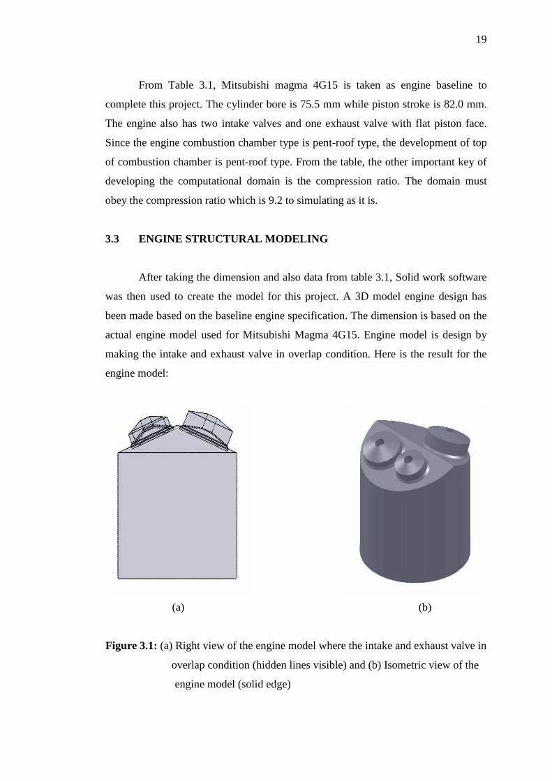
From Table 3.1, Mitsubishi magma 4G15 is taken as engine baseline to
complete this project. The cylinder bore is 75.5 mm while piston stroke is 82.0 mm.
The engine also has two intake valves and one exhaust valve with flat piston face.
Since the engine combustion chamber type is pent-roof type, the development of top
of combustion chamber is pent-roof type. From the table, the other important key of
developing the computational domain is the compression ratio. The domain must
obey the compression ratio which is 9.2 to simulating as it is.
3.3 ENGINE STRUCTURAL MODELING
After taking the dimension and also data from table 3.1, Solid work software
was then used to create the model for this project. A 3D model engine design has
been made based on the baseline engine specification. The dimension is based on the
actual engine model used for Mitsubishi Magma 4G15. Engine model is design by
making the intake and exhaust valve in overlap condition. Here is the result for the
engine model:
(a) (b)
Figure 3.1: (a) Right view of the engine model where the intake and exhaust valve in
overlap condition (hidden lines visible) and (b) Isometric view of the
engine model (solid edge)

20
3.4 GRID GENERATION AND DOMAIN CREATION
The model that was created was then imported to ANSYS to start the grid
generation or meshing process in order to simulate the actual engine motion. To
define the deforming cylinder volume and valve face volume hexahedral meshed was
used while for deforming combustion chamber tetrahedral meshed was used and is
shown by figure 3.2. Moving boundary is selected for the piston face and the upper
and lower faces of the valves. Stationary parts are defined for all manifolds and pent-
roof walls.
Figure 3.2: Engine meshing
Piston is moving wall
Both combustion chamber and cylinder are deforming walls
Hexahedral mesh zone for deforming cylinder
Tetrahedral mesh zone for deforming combustion chamber All pent-roof
walls are stationary
All manifolds walls are stationary

21
3.5 GOVERNING EQUATION FOR COMPUTATIONAL FLUID
DYNAMICS
CFD represent a vast area of numerical analysis in the field of fluid’s flow
phenomena. CFD is much more than just computer and numerical science. Since
direct numerical solving of complex flows in real-like conditions requires an
overwhelming amount of computational power success in solving such problem is
very much dependent on the physical model applied. CFD methodology in FLUENT
is using partial differential equations of flow variables to calculate and to simulate
numerous kinds of analysis concerning the fluid flow. Among them is mass,
momentum, energy, species concentration, quantities of turbulence and mixture
fractions.
3.5.1 Mass Conservation Equation
The continuity equation or the mass conservation equation for any fluid flow
is expressed as below (Fluent, 2004):
556 +
5567 �8u7� = m; (3.1)
where
8 : Fluid density
u7 : The jth Cartesian component of instantaneous velocity
m; : The rate of mass of the object generated in the system
This equation is valid for the incompressible and compressible flow.
Moreover, the rate generated in the system, m; can be defined as the mass added to
continues phase from the dispersed second phase such the vaporization of the liquid
droplets and any other user-defined sources.

22
3.5.2 Momentum Conservation Equation
The conservation of momentum in i direction for an inertial reference frame
can be explained as (Fluent, 2004):
55 �8u<� + 5
567 �8u<u7� = 5�56< + 5=<7
567 + 8g? + @? (3.2)
where
8 : Fluid density
u<&B7 : The ith and jth Cartesian components of the instantaneous velocity
p : Static pressure
C?D : Stressor tensor
8gi : Gravitational body force
Fi : External body force from interaction with dispersed phase in I
direction
The stress tensor in Equation 3.2 is given as below:
C?D = F�GB?G,D +
5H756<) -
'I F�5HJ
56J��ij (3.3)
where
F : Fluid dynamic viscosity
�ij : Kronecker delta
Note that the second term on the right hand side of Equation 3.2 describes the
effect of volume dilation. By substituting Equation 3.3 into Equation 3.2, another
equation is produced that is complete momentum conservation equation (Fluent,
2004):
55 �8u<� + 5
567 K8u<u7L = − 5�56< + 5�
567 { F N5H<567 + 5H7
56<O − 'I F N5HJ
56JO �PQ}ρgi + @? (3.4)

23
3.5.3 Energy Conservation Equation
55 �8T� + 5
56< Uu<�8T + ��V = 556< UKXYY Z[
Z\P − ∑QhQJQ + uQ�τPQ�XYYV + Sb (3.5)
where
KXYY : Effective conductivity
: k + ki (where kt = turbulent thermal conductivity)
Jj : Diffusion flux of species j
Sh : Additional volumetric heat sources (example: heat of chemical
reaction)
h : Sensible enthalpy
e : Specific total energy
The first three terms on the right-hand side of equation 3.5 represent the
energy transfer due to conduction, species diffusion and viscous dissipation
respectively. From equation 3.5 also, sensible enthalpy, h and specific total energy, e
are defined as below:
e = h - � +
H<c' (3.6)
sensible enthalpy for ideal gas is defined as:
h = ∑j mjhj (3.7)
sensible enthalpy for incompressible flow is defined as:
h = ∑j mjhj + � (3.8)
where
mj : mass fraction of species j
hj : d e�.7��fg� dT with Tref = 298.15K

24
3.6 PREMIXED COMBUSTION THEORY
Based on work by Zimont (Zimont, 2000), the turbulent premixed
combustion model, involves the solution of a transport equation for the reaction
progress variable. The closure of this equation is based on the definition of the
turbulent flame speed.
3.6.1 Progress variable
As the flame front moves, combustion of unburnt reactants occurs, converting
unburnt premixed reactants to burnt products. The premixed combustion model thus
considers the reacting flow field to be divided into regions of burnt and unburnt
species, separated by the flame sheet. The flame front propagation is modeled by
solving a transport equation for the density-weighted mean reaction progress
variable:
5 hi5 + 5 hHkli
56l = 556l m no
pio5i
56lq + 8�i (3.9)
where
e : Reaction progress variable
�e� : Turbulent Schmidt number
�i : Reaction rate source term
The progress variable is defined as a normalized sum of the product species.
e = ∑ rstsuv∑ rs,wxtsuv (3.10)
where
n : Total number of products
yJ : Mass fraction of product species k
yJ,gz : Equilibrium mass fraction of product species k