mpt 1343 - sepuraftp.fyldemicro.com/downloads/mpt-standards/mpt1343.pdf · - signalling...
TRANSCRIPT
MPT 1343
Performance Specification
System Interface Specification forradio units to be used with commercialtrunked networks operating in Band III
sub-bands 1 and 2
January 1988
Revised and reprinted September 1991Revised and reprinted June 1997

MPT1343 1997 Issue ( i )
Crown Copyright 1988First Published 1988Revised and reprinted September 1991Revised and reprinted June 1997
MPT1343 1997 Issue ( ii )
FOREWORD
This specification contains the minimum performance requirements additional toMPT 1323 to be met by radio units used with commercial trunked networksoperating in Band III, sub-bands 1 and 2. A companion specification, MPT 1347,contains the additional minimum performance requirements to be met by networkfixed equipment. Together these common specifications are intended to allow auser to migrate from one trunked radio network to another without having to changeradio equipment.
It should be noted that some aspects of the specification remain relatively unprovenoperationally. All reasonable efforts have been made to ensure accuracy, but it mayprove necessary to amend some sections in the light of practical experience. Anexample is the way that the radio unit caters for time-shared and discontinuouscontrol channels.
Intellectual Property Rights
Firms intending to manufacture equipment which complies with the specificationshould be aware that certain features of the specification are subject to IPR claims.
All firms are therefore advised that they should make appropriate enquiriesthrough their Patent Agents before proceeding.
MPT1343 1997 Issue ( iii )
CONTENTS
1. SCOPE
2. ASSOCIATED DOCUMENTS
3. GENERAL3.1 Definitions 3.2 Test Conditions3.3 General Requirements
4. TRANSMITTER PARAMETERS4.1 Frequency Parameters 4.2 Modulation Characteristics 4.3 Performance Parameters
5. RECEIVER PARAMETERS5.1 Frequency Parameters 5.2 Demodulation Characteristics 5.3 Muting 5.4 Performance Parameters
6. STORAGE REQUIREMENTS6.1 Introduction 6.2 Types of Memory 6.3 Summary of Storage Requirements
7. SECURITY
8. MAN-MACHINE INTERFACE8.1 Confidence Indications 8.2 Call Number Convention 8.3 Ready for Communication Control
9. CONTROL CHANNEL ACQUISITION AND RETENTION9.1 Introduction 9.2 Radio Unit Storage Requirements 9.3 Control Channel Acquisition Procedures 9.4 Leaving a Control channel 9.5 Multiple Control Channels
10. REGISTRATION10.1 General 10.2 Single Registration 10.3 Multiple Registration
MPT1343 1997 Issue ( iv )
Page11. CALL PROCESSING
11.1 Introduction 11.2 Definitions 11.3 Signalling Formats 11.4 Addressing 11.5 Codeword Structure 11.6 Channel Discipline 11.7 Random Access Protocol 11.8 Registration Procedures 11.9 Basic Call Procedures 11.10 Emergency Call Procedures 11.11 Include Call Procedures 11.12 Call Diversion Procedures 11.13 Status Message Procedures 11.14 Short Data Message Procedures 11.15 Data Interrogation Procedures 11.16 Not Used 11.17 Standard Data procedures
12. NON-STANDARD DATA INTERFACE PROVISION12.1 Muting 12.2 Maladjustment 12.3 Standard Signalling12.4 Data Call Handling 12.5 Facilities
13. FALL-BACK MODE
13.1 Introduction 13.2 Storage Requirements 13.3 Entering Fall-back Mode 13.4 Procedures in Fall-back Mode 13.5 Leaving Fall-back Mode 13.6 User Initiated Change of Network
14. SHORT DATA ON THE CONTROL CHANNEL USING RQC14.1 Introduction 14.2 Message Format 14-3 The use of Control Fields for STF = '1' 14-4 Procedure for Radio units 14-5 An Example of the Procedures for
Extended Data Messages
MPT1343 1997 Issue ( v )
APPENDIX A ERROR PERFORMANCE REQUIREMENTSA.1 Definition A.2 Method of Measurement A.3 Limits
APPENDIX BTIMING AND DEFAULT APRAMETERSB.1 Default Parameters B.2 Timing Parameters
ANNEX AN1 Clarification of Radio Unit Operation on Time SharedControl Channels
AN2 Recommendation for Radio Unit Behaviour once theComprehensive Hunt Sequence has been entered
AN3 Acquiring and Relinquishing a Control Channel
AN4 Notes relating to the use of the INFO field in Request to Register RQR message
AN5 Notes regarding the implementation of Registrationon Demand in radio units. Issues of NetworkCompatibility
AN6 Dynamic Regroup Operation

MPT1343 1997 Issue Page (1)
1. SCOPE
1.1 This specification covers the minimum performance requirements for radiounits used with commercial trunked networks operating in Band III, sub-bands1 and 2. It covers:
- signalling requirements based upon the standard MPT 1327.
MPT 1343 is designed to be read in association with MPT 1327.
- radio frequency requirements, where they are additional to those inMPT 1323.
- user interface requirements, where advantages are to be gained fromstandardisation.
1.2 The specification includes two types of requirement:
- those that are mandatory in all radio units.
- those that are optional in a radio unit, but shall be implemented in astandard manner.

MPT1343 1997 IssueMPT1343 1997 Issue Page 2-11
2. ASSOCIATED DOCUMENTS
MPT 1317 (1981) Code of practice for the transmission of digital information overland mobile radio systems.
MPT 1318 (1986) Engineering memorandum: Trunked systems in the land mobileservice.
MPT 1323 (1987) Angle modulated radio equipment for use at base and mobilestations in the private mobile radio service operating in thefrequency band 174-225 MHz.
MPT 1327 (1988) A signalling standard for trunked private land mobile radiosystems.
MPT 1331 (1987) Code of practice for radio site engineering.
MPT 1347 (1988) Radio interface specification for commercial trunked networksoperating in Band III sub-bands 1 and 2.
MPT 1352 (1991) Test schedule for the approval of radio units to be used withcommercial trunked networks operating in Band III sub-bands 1and 2.
MAP27 Access Interface Standard for Trunked Radio Systems
MPT1343 1997 Issue Page 3-1
3. GENERAL
3.1 Definitions
Section numbers appearing between !! !! delimiters in this specification refer to sectionnumbers within MPT 1327.
Words appearing between asterisks in this section are defined terms.
Acquisition: The condition obtained by the successful completion of the *control channelacquisition procedure* for a control channel which allows a radio unit to transmit on thatchannel.
Acquisition Authorisation Data: *Network personalisation* data which enables the *radiounit* to determine by examination of the relevant sub-fields within a *system identity code*received on a *control channel* whether the *radio unit* is authorised to access on that*control channel*.
Active on a Channel: A *radio unit* is *active on a channel* when, on that channel, it isenabled to respond to *messages* addressed to it, or is transmitting, or is in transitionbetween the two states.
Note: a *radio unit* becomes active on an assigned *traffic channel* as soon as it canreceive on that channel, whereas, on a *control channel* it shall not become activeuntil it has received a codeword containing an appropriate *system identity code*.
Address: A 20-bit number by which a unit or group of units is known within a *system*. The*address* comprises two *fields*; a 7-bit *prefix* and a 13-bit *ident*.
Address Codeword: A 64-bit codeword, conforming to the requirements of MPT 1327,where the first bit is set to '1'. An *address codeword* is always the first codeword in any*message*, and defines the nature of the *message*.
Available for Customisation: If the *trunking system controller* implements such acustomised function, then if the *radio unit* implements the function it shall respond in themanner specified by the network operator of that *trunking system controller*. Suchfunctions will not modify existing standardised functions. If the radio unit does notunderstand the customised function in the context of a *system* it is currently using, then itshall ingnore that function. The *radio unit* shall not infringe any of the requirements ofsection 5 of MPT 1327.
Base Station: The entirety of transmitters and receivers operated by a *trunking systemcontroller* at any one site.
Call: A complete information exchange between two or more *parties* which includes oneor more *transactions* and may include direct user-to-user communication on a *trafficchannel*.
Called Unit (or Group): The unit, or group of units, which a *calling unit* identifies as thedesired recipient(s) of a *call*. The *called unit (or group)* retains this designation for theduration of the *call* and this convention is used in messages relating to that particular*call* irrespective of the origin of such *messages*.
Page 3-2 MPT1343 1997 Issue
Calling Unit: A *radio unit* or *line unit* which requests a *call*. The *calling unit* retainsthis designation for the duration of a *call* and this convention is used in *messages*relating to that particular *call* irrespective of the origins of such *messages*.
Common Prefix Call: A *call* where the values of the *prefixes* in the calling and called*addresses* are the same. *Common prefix calls* use *short addressing* procedures.
Confirmation: A procedure employed by the *radio unit* to facilitate the selection of anappropriate *control channel* to allow a *session* with a *system* to be initiated orcontinued. The *confirmation* process consists of applying prescribed tests to the signalcontent of the received *forward channel*.
Control Category: A designation given to the *radio unit* during *network personalisation*which governs that unit's right of access to *control channels* radiated by that *network*. A*radio unit* shall only access a *control channel* when the value of the LAB field in the*system identity code* indicates that the unit's *control category* is permitted to use thatchannel.
Control Channel: A *forward channel* and *return channel* being used for the transmissionof *messages* conforming to MPT 1327 with the primary purpose of enabling the *trunkingsystem controller* to control *radio units*.
Control Channel Acquisition Procedure: A procedure employed by the *radio unit* to selectan appropriate *control channel* to allow a *session* with a *system* to be initiated orcontinued. The procedure consists of *hunting* for candidate *control channels* which aresubmitted to *confirmation* tests to determine if *acquisition* is permitted. *Hunting*continues until such time as a successful *acquisition* is confirmed.
Data Codeword: A 64-bit codeword, conforming to the requirements of MPT 1327, wherethe first bit is set to '0'. *Data codewords* are concatenated to an *address codeword* andsupplement the information in the *address codeword*.
Decodable: A transmitted codeword shall be considered *decodable* if, after receipt, andafter error correction (see Section 11.3.2.3) has been applied, a valid codeword from the(64,48) code defined in section 3.2.3 of MPT 1327 is formed.
Diversion: A procedure whereby a *party* may request that future *calls* to a particularcalled *address* be directed to an alternative destination.
Explicit Registration: A *registration* achieved by means of an RQR message.
Extended Addressing: A method which allows called *party* details to be conveyed to the*trunking system controller* when the *call* details cannot be accommodated in a single*address codeword*. These called-party details may be an *address* or addressinginformation in a different form (eg PSTN dialling digits).
Fall-back Mode: A customised form of operation which may be used by a *network*suffering equipment malfunction.
Field: A number of contiguous bits in a codeword which is specified in terms of the positionwithin the codeword and the number of bits.
MPT1343 1997 Issue Page 3-3
Fixed Radio Unit: A *radio unit* used with its antenna at a fixed location.
Forward Channel: A radio bearer where the direction of transmission is from the *trunkingsystem controller* to the *radio units*.
Free Format Data: Data within a codeword which, in this specification, is constrained onlyby its position and length.
Gateway: A *special ident* which is used to identify a *message* relating to a *call ortransaction* to or from a communications service outside the *system* (eg the PSTN). Forthe purpose of this specification the interprefix *ident*, IPFIXI, is also regarded as a*gateway*.
Group Address: An *address* which is common to more than one unit and which, whennominated as the called *address*, signifies a *group call*. Units may be assigned anypracticable number of *group addresses*.
Group Call: A *call* in which a *group address* is specified as the called *party* and,accordingly, provides a means of communication between more than two units. The calling*party* in a *group call* may opt for a conversational mode, where all *parties* are able tospeak, or for an announcement mode where only the caller may speak.
Head Message: Single transmission of an MPT1327 HEAD *address codeword* and itsappended *data codewords*.
Hunting: A procedure employed by the *radio unit* to facilitate the selection of anappropriate *control channel* to allow a *session* with a *system* to be initiated orcontinued. The *hunting* process consists of systematic sampling of the *forward channel*frequencies by the *radio unit* until it selects and *confirms* one of the *forward channels*,which together with its paired *return channel* is an appropriate *control channel*.
Hunting Sequence: A procedure employed by the *radio unit* during *hunting* whichconsists of one or more *hunting stages*. There are five described *hunting sequences*:
(a) "Resuming a control channel sequence"(b) "Single channel hunt sequence"(c) "Preferential hunt sequence"(d) "Normal hunt sequence"(e) "Comprehensive hunt sequence"
A *hunting sequence* is completed when all *hunting stages* appropriate to that *huntingsequence* have been completed or, prior to this, if a successful *control channel**confirmation* is achieved.
Hunting Stage: A procedure employed by the *radio unit* during *hunting* which consists ofsampling all channel numbers applicable to the type of *hunting sequence* in progress at aparticular acquisition threshold level. A *hunting stage* is completed when all channelnumbers applicable have been sampled and *confirmation* attempted on any candidate*control channels* located or may be completed prior to this if a successful *controlchannel* *confirmation* is achieved.
Ident: A 13-bit number used for identification purposes. Values of *ident* between 1 and8100 inclusive are assigned to individual units or groups (see section 8.2), in which case

Page 3-4 MPT1343 1997 Issue
they are associated with a *prefix* to form a 20-bit address. Values of *ident* above 8100are designated *special idents* and these are not associated with any particular *prefix*,nor is the *ident* value 0 (DUMMYI).
Idle State: A *radio unit* is in the *idle state* on a *system* when it is *active on a channel*,is receiving on an appropriate *control channel* from the *system*, is not currently within a*message* exchange and has no current *message* transfer requirement.
Implicit Registration: A *registration* achieved by means other than an RQR message andassociated Acknowledgement message from the *network*.
Include: A procedure whereby *parties* may be introduced into a *call* in progress at therequest of an existing *party* to the *call*.
Individual Address: An *address* by which a single unit is known within a *system*, allowingthat unit to be uniquely addressed by that *system*. Units may be assigned any practicablenumber of *individual addresses* provided that at least one is assigned to each unit.
Individual Call: A *call* between a calling *party* and a single called *party*.
Interprefix Call: A *call* where the values of the *prefixes* in the calling and called*addresses* are different. *Interprefix calls* require *extended addressing* procedures.
Item: A complete user transmission on a traffic channel by one *party* within a *call* at theconclusion of which that *party* rests from transmission. It is possible for a *call* to containonly one *item*.
Line Unit (LU): A user station which is allocated an *individual address* and is directlyconnected to a *trunking system controller* via a medium other than that part of the radiospectrum to which this specification applies.
Mandatory: The *radio unit* shall implement the function or facility.
Message: A single contiguous data transmission which consists of a codewordsynchronisation sequence, an *address codeword* and (optionally) one or more *datacodewords* conforming to MPT 1327.
Network: Interconnected *systems*.
Network Personalisation: A procedure undertaken when a subscription to *network* istaken out by a user whereby that user's *radio units* are implanted with data to enable it tofunction correctly on that *network*. *Radio units* which are required to access more thanone *network* shall be personalised for each *network* to be accessed.
Non-dedicated: A procedure which may be adopted by a *trunking system controller*whereby channels used by the *system* may be flexibly allocated as *control channels* or*traffic channels* depending on the traffic load on the *system*. When this procedure isemployed, the current *control channel* would normally be allocated as a *traffic channel*when all other channels are in use for traffic and the *control channel* facility restoredwhen possible, eg by allocating the next *traffic channel* to become free as a new *controlchannel*.
MPT1343 1997 Issue Page 3-5
Non-prescribed data: Any data traffic which does not conform to the data protocols definedin MPT 1327.
Normal Operation Mode: The operation mode of a *radio unit* or *control channel* which isnot in the *fall-back mode*.
Normal Registration Mode: A *control channel* mode in which the *network* will accept andmaintain *registration* requests.
Normal Registration Record: A *registration* record which has an indication that the*network* is maintaining the *registration* record.
Null Registration Record: A *registration* record which includes a NULL indicator togetherwith the AREA code.
Party: A source and/or recipient of information within a *call*. The term includes the totalityof equipment at the user station and, where the context permits, the equipment user. A*party* may be an individual or a group.
Personality: The totality of *network personalisation* data entered into the *radio unit*.
Portable radio unit: A portable radio unit is distinguished from any other radio unit by thefollowing criteria:-
- the equipment covered is intended to be used only with an integral antenna, whichmay be detachable. When this equipment is used with a non-integral antenna itceases to be defined as a portable radio unit for the purpose of this specification;
- the maximum effective radiated power shall not exceed 5 watts;- the equipment shall be powered by a self contained battery unit.
Prefix: The 7 most significant bits of an *address*. Normally units within a fleet will beallocated the same *prefix* since *calls* between units and groups with the same *prefix*can be made without the use of *extended addressing* procedures. A *prefix* is onlyrelevant to *individual addresses* and *group addresses*.
Prime Registration Record: The most recently created *registration* record held by the*radio unit*. Note that the *prime registration record* does not include timing information.
Radio Unit (RU): A mobile or other user station contacting a *system* by normal landmobile radio in accordance with the specification.
Random Access Attempt: The method by which a *radio unit* transmits an unsolicited*message* to the *trunking system controller* on a *control channel*. The method requiresthat a *radio unit* repeats a random access *message* if a response *message* is notreceived within a designated waiting time. Further repeats are required, in the absence ofan appropriate acknowledgement, until a designated number of repeats is reached. In thisspecification a *random access attempt* covers the period from initiation of the*transaction* to the receipt of an appropriate acknowledgement or the expiry of a timeout.
Read-only Memory: A storage facility within the *radio unit* which contains *networkpersonalisation* data. The contents of the *read-only memory* cannot be modified oradded to by the action of the *radio unit* or its user. It is intended that the contents of
Page 3-6 MPT1343 1997 Issue
*read-only memory* are placed there only during *network personalisation* by a suitablyauthorised agent (normally a service provider).
Read/Write Memory: a storage facility within the *radio unit* the contents of which may bemodified by the *radio unit*.
Ready for Communication Control (RFCC): A device or system to inform a unit of the user'sreadiness to communicate (see section 8.3).
Registration: A procedure which confirms that a *radio unit* is in a *session* on a *system*.The *registration* procedures may be initiated by a demand from the *trunking systemcontroller*, or at the initiative of the *radio unit*, depending on the circumstances of theregistration.
Requested Unit (or Group): A unit, or group of units, which takes part in a *transaction*initiated by the *trunking system controller* or another *party*.
Requesting Unit: A *radio unit* or *line unit* which initiates a *transaction* with the *trunkingsystem controller* or another *party*, via the *trunking system controller*.
Reserved: Codewords and *fields* which are designated as *reserved* in MPT 1327 areintended for future phases of standardisation and shall not be used in the interim for theconveyance of information. *Reserved fields* must be set to the default value specified inMPT 1327.
Return Channel: A radio bearer where the direction of transmission is from *radio units* tothe *trunking system controller*.
Segment: For a known *transaction*, the portion of the *T-message* contained in a *HEADmessage*.
Selected Network: The *network* which the user of the *radio unit* has selected for thetime being and which is the only *network* that the *radio unit* may attempt to access untilsuch time as the user designates a new *selected network*. Where the *radio unit* doesnot allow the user to select from a choice of *networks* then only one *network* shall beavailable to that *radio unit* for access and this *network* shall be, per se, the *selectednetwork*.
Session: A *session* is a period of operation associated with one *system*. A *session* ona *system* starts when a *radio unit* becomes *active on a control channel* of that*system*, either after switch on or after being *active on a control channel* of a different*system*. A *session* ends either when the *radio unit* is switched off or when it starts itsnext *session*.
Short Addressing: The method used when the *parties* to a *call* can be completelyspecified by a single *prefix* and two *idents*. This form of addressing minimises thesignalling required.
Short Data: A procedure which allows a data *message* to be exchanged between*parties* or between *parties* and the *trunking system controller*. This procedure doesnot support *messages* which include more than four *data codewords*.
MPT1343 1997 Issue Page 3-7
Short-Form PSTN Destination: A called PSTN *party* previously agreed between thesystem operator and the user of the *calling unit* which can be specified by a *specialident* rather than the full stream of dialling digits representing the directory number.
Single Segment Transaction (SST): Short data *transaction* requiring only one *segment*.
Spare: Codewords and *fields* which are designated *spare* are available for free use by*systems* (ie *system* customisation) provided that the conditions of MPT 1327 are notinfringed. The use of *spare* codewords and *fields* may vary from *system* to *system*.
Special Ident: An *ident* with a value greater than 8100. These *idents* are used for avariety of special purposes. Some of these are specified in MPT 1327, others may benominated by system operators. *Special idents* are not associated with a *prefix* to forman *address*.
Speech Call: A *call* as a result of the receipt of a GTC *message* with the 'D' *field* set to'0'. The audio is not muted.
Standard Data: The procedure by which information exchange takes place using the dataprotocol defined in section 17 of MPT 1327.
Standard Option: Any optional feature for which the implementation has been standardisedin MPT 1327. Any unit implementing such an option shall implement it at least in thespecified standardised manner. Units and *systems* shall not infringe any of thestandardised formats in MPT 1327 when implementing customised features.
System: The totality of equipment required to provide the communication facilities at onelocation, associated with one or more *system identity codes*. *Systems* may becombined to form larger communications facilities.
System Identity Code: A 15-bit number which identifies a *system*. This code is radiatedon each *forward control channel* within the *system* (in the SYS *field*).
T-message: totality of *free-format data* which is intended to be conveyed in a *short data**transaction*.
Temporary Registration Mode: A *control channel* mode in which the *network* will acceptbut may not maintain *registration* requests. The *radio unit* may be required to re-register when the *normal registration mode* is resumed.
Temporary Registration Record: A *registration* record which has an indication that the*network* may not be maintaining the *registration* record.
Timed Registration Record: A *registration* record held by the *radio unit*, that has beendisplaced from the *prime registration record*. The record has a timer TD associated withit.
Traffic Channel: A *forward channel* and *return channel* being used primarily for usercommunications.
Transaction: A complete information exchange consisting of one or more *messages*between a *party* and the *trunking system controller*, or another *party*, via the *trunkingsystem controller*.
Page 3-8 MPT1343 1997 Issue
Trunking System Controller (TSC): The central control intelligence necessary to enable thetrunking system to function according to MPT 1327. The *trunking system controller* maycontrol one or more *base stations*.
Undefined Registration Record: A *registration* record which has no indication that the*network* may or may not be maintaining the *registration* record.
Verified AREA code: The AREA subfield of the received *system identity code* (SYS) usedto verify a *control channel*.
Verified SIL code: The SIL field of the *system identity code* (SYS) received and verified bya *radio unit* from the *control channel* on which that *radio unit* was most recently*active*.

MPT1343 1997 Issue Page 3-9
3.2 Test Conditions
Unless otherwise specified, the *radio unit* shall meet the requirements of thisspecification under extreme test conditions, as defined in MPT 1323 section 2.4
3.3 General Requirements
The *radio unit* shall not operate duplex.
The facility to switch from one *network* to another is a *standard option*.
If implemented, it is *mandatory* that *network* switching shall be under control ofthe user. Autonomous switching between *networks* by the *radio unit* shall not bepermitted.
It shall be possible to transfer, between *network(s)* in a *radio unit* by changingthe *personality* (see section 6).
MPT1343 1997 Issue Page 4-1
4. TRANSMITTER PARAMETERS
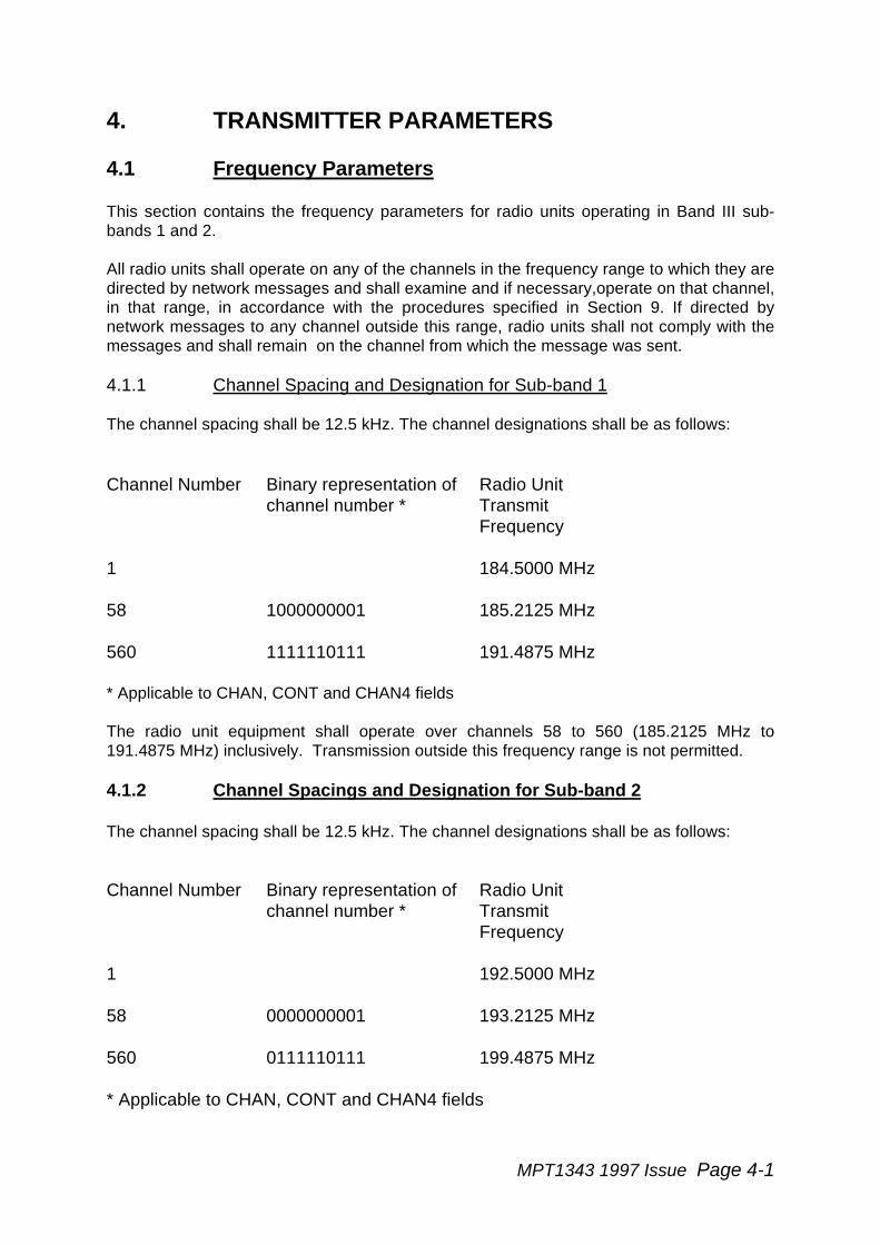
4.1 Frequency Parameters
This section contains the frequency parameters for radio units operating in Band III sub-bands 1 and 2.
All radio units shall operate on any of the channels in the frequency range to which they aredirected by network messages and shall examine and if necessary,operate on that channel,in that range, in accordance with the procedures specified in Section 9. If directed bynetwork messages to any channel outside this range, radio units shall not comply with themessages and shall remain on the channel from which the message was sent.
4.1.1 Channel Spacing and Designation for Sub-band 1
The channel spacing shall be 12.5 kHz. The channel designations shall be as follows:
Channel Number Binary representation ofchannel number *
Radio UnitTransmitFrequency
1 184.5000 MHz
58 1000000001 185.2125 MHz
560 1111110111 191.4875 MHz
* Applicable to CHAN, CONT and CHAN4 fields
The radio unit equipment shall operate over channels 58 to 560 (185.2125 MHz to191.4875 MHz) inclusively. Transmission outside this frequency range is not permitted.
4.1.2 Channel Spacings and Designation for Sub-band 2
The channel spacing shall be 12.5 kHz. The channel designations shall be as follows:
Channel Number Binary representation ofchannel number *
Radio UnitTransmitFrequency
1 192.5000 MHz
58 0000000001 193.2125 MHz
560 0111110111 199.4875 MHz
* Applicable to CHAN, CONT and CHAN4 fields
Page 4-2 MPT1343 1997 Issue
The radio unit equipment shall operate over channels 58 to 560 (193.2125 MHz to199.4875 MHz) inclusively. Transmission outside this frequency range is not permitted.
4.1.3 Frequency Tolerance
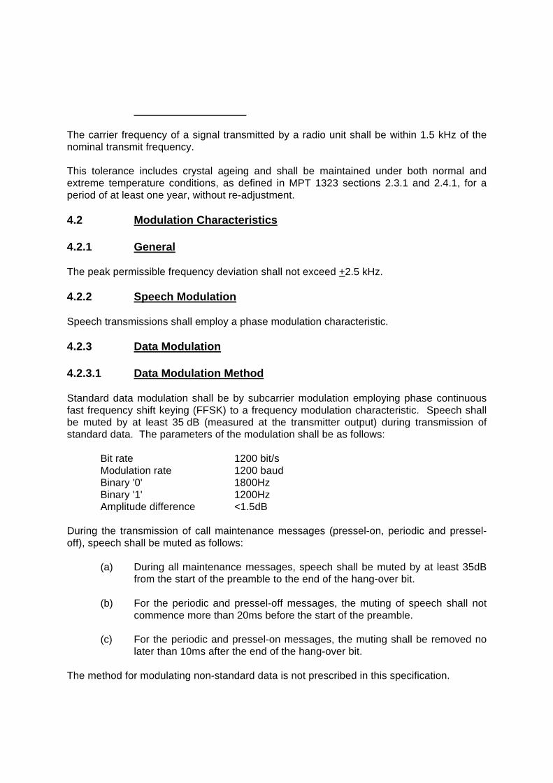
The carrier frequency of a signal transmitted by a radio unit shall be within 1.5 kHz of thenominal transmit frequency.
This tolerance includes crystal ageing and shall be maintained under both normal andextreme temperature conditions, as defined in MPT 1323 sections 2.3.1 and 2.4.1, for aperiod of at least one year, without re-adjustment.
4.2 Modulation Characteristics
4.2.1 General
The peak permissible frequency deviation shall not exceed +2.5 kHz.
4.2.2 Speech Modulation
Speech transmissions shall employ a phase modulation characteristic.
4.2.3 Data Modulation
4.2.3.1 Data Modulation Method
Standard data modulation shall be by subcarrier modulation employing phase continuousfast frequency shift keying (FFSK) to a frequency modulation characteristic. Speech shallbe muted by at least 35 dB (measured at the transmitter output) during transmission ofstandard data. The parameters of the modulation shall be as follows:
Bit rate 1200 bit/sModulation rate 1200 baudBinary '0' 1800HzBinary '1' 1200HzAmplitude difference <1.5dB
During the transmission of call maintenance messages (pressel-on, periodic and pressel-off), speech shall be muted as follows:
(a) During all maintenance messages, speech shall be muted by at least 35dBfrom the start of the preamble to the end of the hang-over bit.
(b) For the periodic and pressel-off messages, the muting of speech shall notcommence more than 20ms before the start of the preamble.
(c) For the periodic and pressel-on messages, the muting shall be removed nolater than 10ms after the end of the hang-over bit.
The method for modulating non-standard data is not prescribed in this specification.
MPT1343 1997 Issue Page 4-3
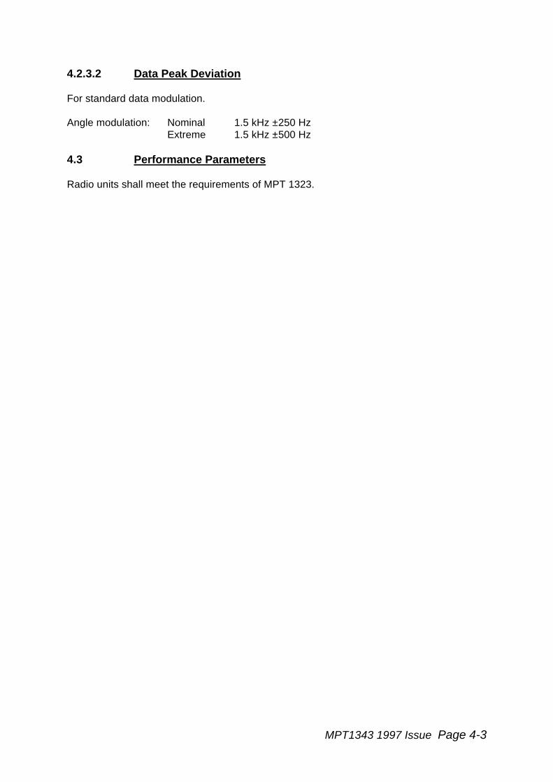
4.2.3.2 Data Peak Deviation
For standard data modulation.
Angle modulation: Nominal 1.5 kHz ±250 HzExtreme 1.5 kHz ±500 Hz
4.3 Performance Parameters
Radio units shall meet the requirements of MPT 1323.

MPT1343 1997 Issue Page 5-1
5. RECEIVER PARAMETERS
The requirements of this section shall be met under normal test conditions, as defined inMPT 1323 section 2.3, unless otherwise specified.
5.1 Frequency Parameters
This section contains the frequency parameters for radio units operating in Band III sub-bands 1 and 2.
All radio units shall operate on any of the channels in the frequency range to which they aredirected by network messages and shall examine and if necessary, operate on thatchannel, in that range, in accordance with the procedures specified in Section 9. If directedby network messages to any channel outside this range, radio units shall not comply withthe messages and shall remain on the channel from which the message was sent.
5.1.1 Channel Spacing and Designations for Sub-band 1
The channel spacing shall be 12.5 kHz. The channel designations shall be as follows:
Channel Number Binary representation ofchannel number *
Radio Unit ReceiveFrequency
1 176.5000 MHz
58 1000000001 177.2125 MHz
560 1111110111 183.4875 MHz
* Applicable to CHAN, CONT and CHAN4 fields
The radio equipment shall receive over channels 58 to 560 (177.2125 MHz to183.4875 MHz) inclusively.
5.1.2 Channel spacing and designations for Sub-band 2
The channel spacing shall be 12.5 kHz. The channel designations shall be as follows:
Binary representation ofchannel number*
Radio Unit ReceiveFrequency
1 200.5000 MHz
58 0000000001 201.2125 MHz
560 0111110111 207.4875 MHz* Applicable to CHAN, CONT and CHAN4 fields
The radio equipment shall receive over channels 58 to 560 (201.2125 MHz to 207.4875MHz) inclusively.
Page 5-2 MPT1343 1997 Issue
5.1.3 Frequency Tolerance
The centre frequency of the response of the radio receiver shall be within 1.5 kHz of thenominal receive frequency except during channel switching.
This tolerance includes crystal ageing and shall be maintained under both normal andextreme temperature conditions, as defined in MPT 1323 sections 2.3.1 and 2.4.1, for aperiod of at least one year, without re-adjustment.
5.1.4 Channel Switching
The radio equipment shall meet the channel switching time requirements of MPT 1327.(See MPT 1327 section 6).
5.2 Demodulation Characteristics
5.2.1 Speech Signals
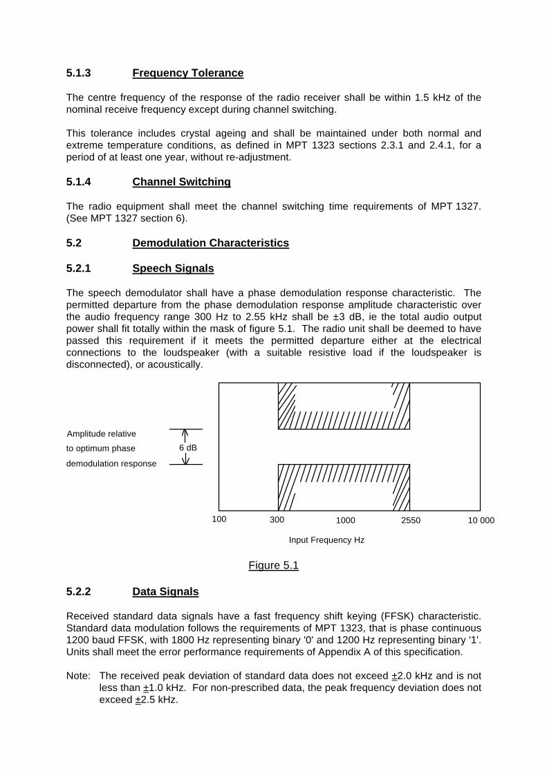
The speech demodulator shall have a phase demodulation response characteristic. Thepermitted departure from the phase demodulation response amplitude characteristic overthe audio frequency range 300 Hz to 2.55 kHz shall be ±3 dB, ie the total audio outputpower shall fit totally within the mask of figure 5.1. The radio unit shall be deemed to havepassed this requirement if it meets the permitted departure either at the electricalconnections to the loudspeaker (with a suitable resistive load if the loudspeaker isdisconnected), or acoustically.
6 dB
Amplitude relative
to optimum phase
demodulation response
100 300 25501000
Input Frequency Hz
10 000
Figure 5.1
5.2.2 Data Signals
Received standard data signals have a fast frequency shift keying (FFSK) characteristic.Standard data modulation follows the requirements of MPT 1323, that is phase continuous1200 baud FFSK, with 1800 Hz representing binary '0' and 1200 Hz representing binary '1'.Units shall meet the error performance requirements of Appendix A of this specification.
Note: The received peak deviation of standard data does not exceed ±2.0 kHz and is notless than ±1.0 kHz. For non-prescribed data, the peak frequency deviation does notexceed ±2.5 kHz.

MPT1343 1997 Issue Page 5-3
5.3 Muting
The audio (other than confidence indications) normally heard by the user shall be mutedwhen one of the following conditions is met:
(a) If the radio unit is not active on a traffic channel.
(b) If a call is set up as a result of the receipt of a GTC message (see MPT 1327section 5.4) with the 'D' bit set to '1' (ie the call is a non-prescribed data call).
(c) If a call is set up as a result of the receipt of a GTT message (ie the call is astandard data call, see MPT 1327 section 5.7.3).
5.4 Performance Parameters
Radio units shall meet the requirements of MPT 1323.
MPT1343 1997 Issue Page 6-1
6. STORAGE REQUIREMENTS
6.1 Introduction
This section tabulates data and parameters which radio units are required to store, eithertemporarily or long-term, in order to carry out functions defined in this specification.
The stored data and parameters may be gleaned by the radio unit from a number ofsources:
- by network personalisation; examples of such data are the radio unit's indi-vidual address and operating parameters which define the required mode ofoperation;
- data implanted into the unit by the manufacturer; this method is specific tothe radio unit security number (see section 7);
- data gleaned from operation on the selected network; examples of such dataare the records of registrations following a registration attempt by the radiounit on an acquired control channel, or data obtained from BCASTmessages received from the selected network.
This section is a compilation of the stipulations expressed in other areas of thisspecification or in MPT 1327 and reference to these should be made for a precise definitionof storage requirements.
Radio units which provide the facility for the user to switch between selected networks shallmaintain sufficient storage for the requirements herein to be met for each network, savethat stored data which is not required to be preserved after a change of selected networkmay be accommodated in common storage areas which may be sufficient for only onenetwork.
The requirement on radio units to store data depends upon the facility for which the data isrequired. For facilities which are mandatory in this specification, the storage of necessarydata is also mandatory and all radio units shall provide storage for data identified asmandatory. For facilities which are optional but must be carried out in a prescribed manner,the storage of applicable data is mandatory only for radio units which employ the option.Storage of such data is regarded as a standard option. Some facilities are optional and arenot fully prescribed. Radio units which employ such options, may choose to follow theprocedure identified in this section for the storage of applicable data. Such storage isregarded as optional.
Where parameters relate to a requirement for the radio unit to measure elapsed time (theparameters T-), the radio unit shall be capable of implementing such measurements to atolerance of ±10%.
6.2 Types of Memory
The storage requirements summarised in this section include a stipulation of the type ofmemory applicable to each item of data. In some cases variation is allowed, and this hasbeen indicated. Four categories of memory are designated:
Type A - Read only memory which may be set by an external agency but not by the actionof the radio unit. The medium of this storage must be such that the data may be reset byan external agency as required to accommodate changes in network subscription details(including changes in network allegiances).
MPT1343 1997 Issue Page 6-2
Type B - Read/Write memory which shall be protected from the effects of switching off theradio unit for a period of at least 120 hours or disconnecting the external source of supplyto the radio unit for a maximum period of 5 seconds. It is permissible for data to be held inunprotected memory whilst operational and transferred to protected memory on powerdown or equivalent. The radio unit shall discard any data held in protected memory unlessits validity is reasonably assured.
Type C - Read/Write memory the contents of which may be discarded at some timebetween switching off the radio unit and being made ready for service after being switchedon subsequently.
Type D - Read only memory, protected by the security measures specified in Section 7.
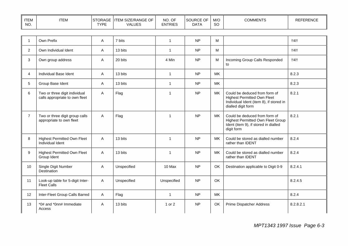
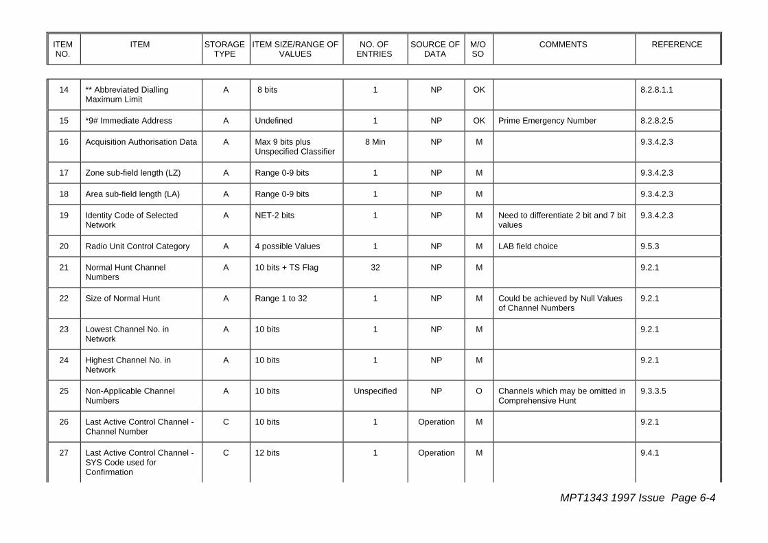
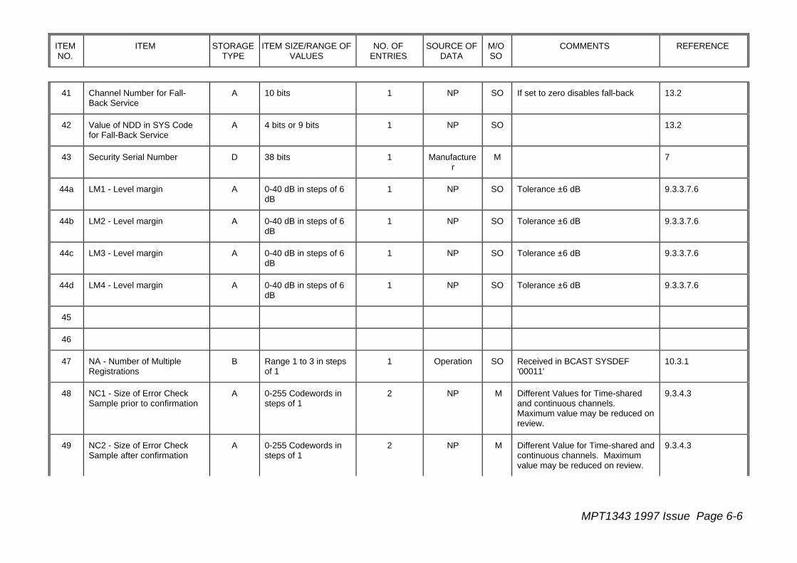
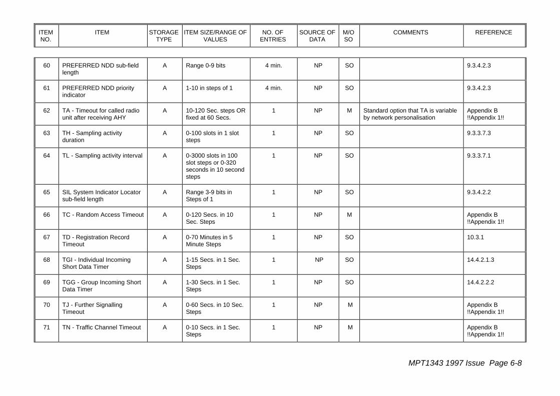
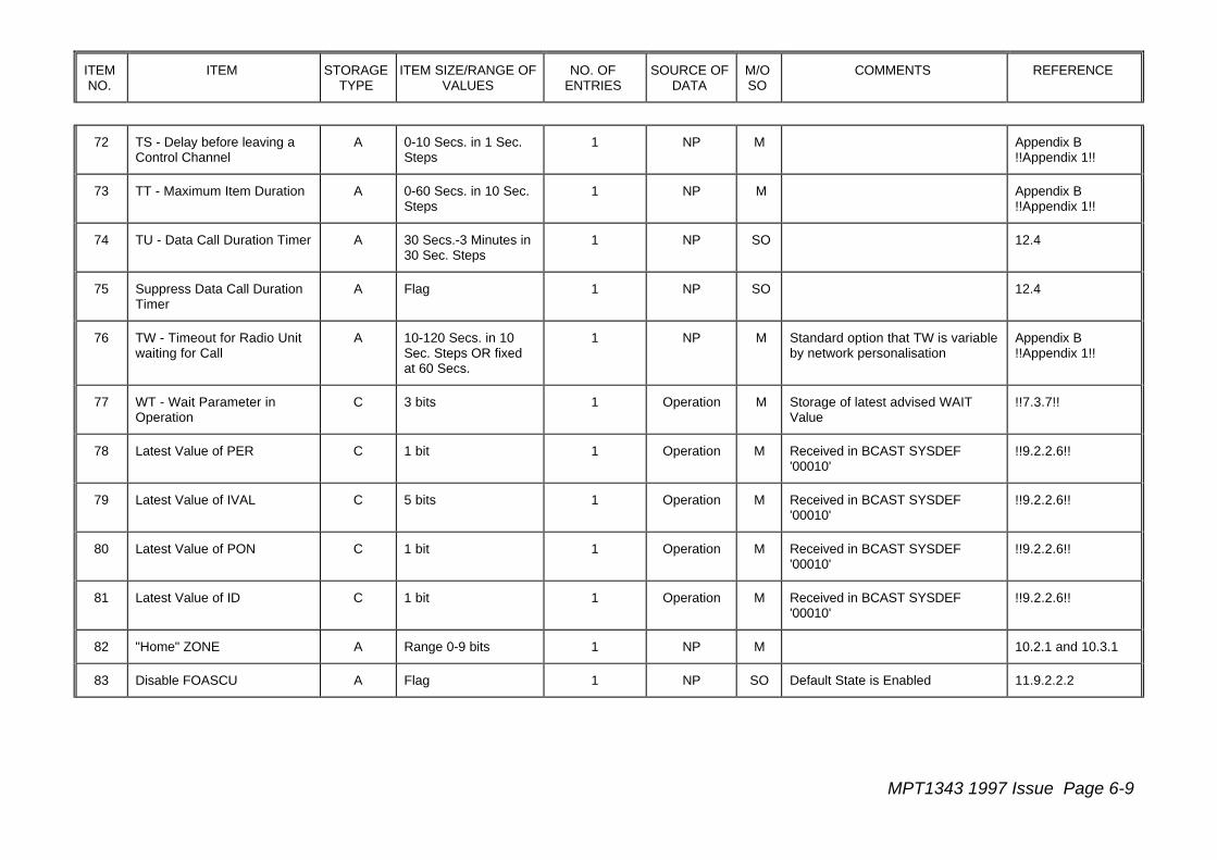
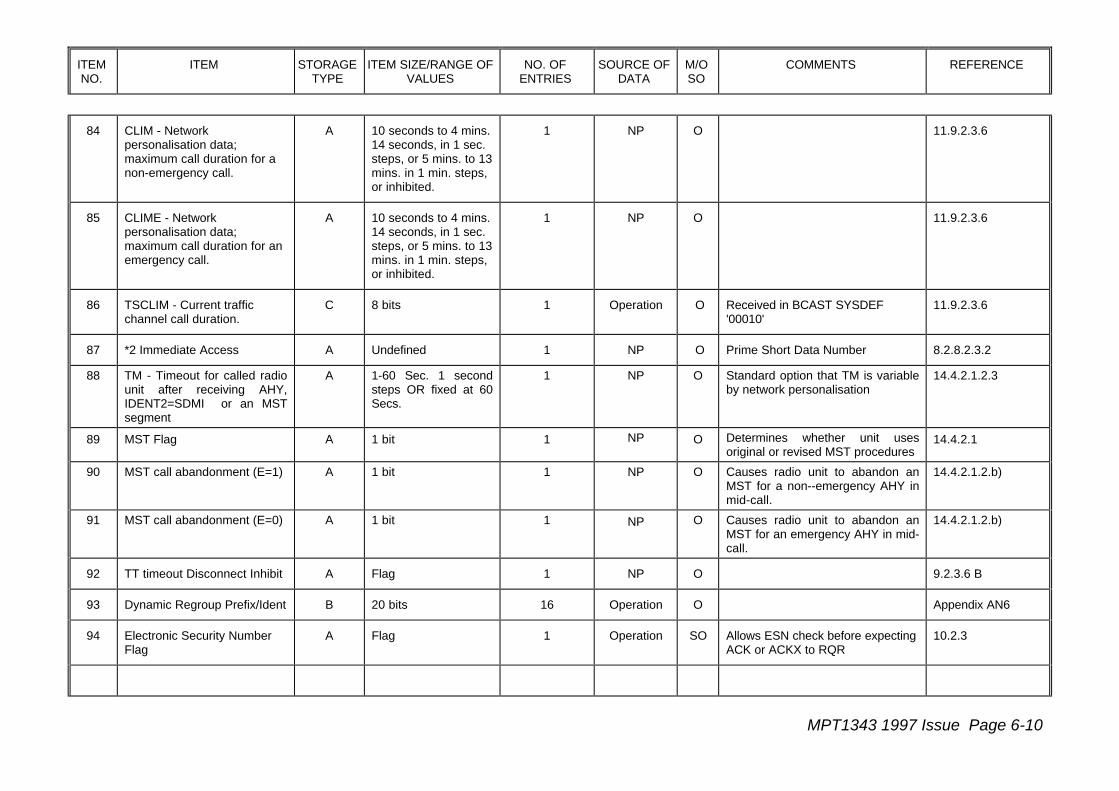
6.3 Summary of Storage Requirements
The radio unit storage requirements are summarised in Table 6.1. The columns of thistable contains the following information:
Column 1 - a serial item number which has no relevance other than allowing ease ofreference to items in the tabulation.
Column 2 - a brief description of the data required to be stored. For a more precise defini-tion of the data, reference should be made to the area of the specification indicated inColumn 8.
Column 3 - the storage category to be used. Type A, B, C or D.
Column 4 - the data item size in bits where this is specified. If not specified, the range ofvalues to be accommodated and granulation, where appropriate, are given. FLAGindicates that one of two possible states must be recorded. Where a range of values and,where appropriate, a granulation are stated these shall be accommodated by the radio unitin its storage allocation. Where the size of the parameter is stated (eg 13 bits), this isprovided for information only and not intended as a limitation on the form in which the radiounit stores the date.
Column 5 - the number of individual records which shall be accommodated. In some casesthe number given is indicated as a maximum or minimum value.
Column 6 - the source of the data. NP indicates network personalisation data.Manufacturer indicates data implanted into the unit by the manufacturer. Operationindicates data gleaned from operation on the selected network.
Column 7 - whether the storage requirement is mandatory (M), a standard option (SO),optional (O), mandatory for units implementing the keypad scheme in section 8.2 (MK) oran option for units implementing the keypad scheme (OK).
Column 8 - comments for clarification.
Column 9 - the area in MPT 1343 or !!MPT 1327!! where the requirement is defined.
ITEMNO.
ITEM STORAGETYPE
ITEM SIZE/RANGE OFVALUES
NO. OFENTRIES
SOURCE OFDATA
M/OSO
COMMENTS REFERENCE
MPT1343 1997 Issue Page 6-3
1 Own Prefix A 7 bits 1 NP M !!4!!
2 Own Individual Ident A 13 bits 1 NP M !!4!!
3 Own group address A 20 bits 4 Min NP M Incoming Group Calls Respondedto
!!4!!
4 Individual Base Ident A 13 bits 1 NP MK 8.2.3
5 Group Base Ident A 13 bits 1 NP MK 8.2.3
6 Two or three digit individualcalls appropriate to own fleet
A Flag 1 NP MK Could be deduced from form ofHighest Permitted Own FleetIndividual Ident (item 8), if stored indialled digit form
8.2.1
7 Two or three digit group callsappropriate to own fleet
A Flag 1 NP MK Could be deduced from form ofHighest Permitted Own Fleet GroupIdent (item 9), if stored in dialleddigit form
8.2.1
8 Highest Permitted Own FleetIndividual Ident
A 13 bits 1 NP MK Could be stored as dialled numberrather than IDENT
8.2.4
9 Highest Permitted Own FleetGroup Ident
A 13 bits 1 NP MK Could be stored as dialled numberrather than IDENT
8.2.4
10 Single Digit NumberDestination
A Unspecified 10 Max NP OK Destination applicable to Digit 0-9 8.2.4.1
11 Look-up table for 5-digit Inter-Fleet Calls
A Unspecified Unspecified NP OK 8.2.4.5
12 Inter-Fleet Group Calls Barred A Flag 1 NP MK 8.2.4
13 *0# and *0nn# ImmediateAccess
A 13 bits 1 or 2 NP OK Prime Dispatcher Address 8.2.8.2.1
ITEMNO.
ITEM STORAGETYPE
ITEM SIZE/RANGE OFVALUES
NO. OFENTRIES
SOURCE OFDATA
M/OSO
COMMENTS REFERENCE
MPT1343 1997 Issue Page 6-4
14 ** Abbreviated DiallingMaximum Limit
A 8 bits 1 NP OK 8.2.8.1.1
15 *9# Immediate Address A Undefined 1 NP OK Prime Emergency Number 8.2.8.2.5
16 Acquisition Authorisation Data A Max 9 bits plusUnspecified Classifier
8 Min NP M 9.3.4.2.3
17 Zone sub-field length (LZ) A Range 0-9 bits 1 NP M 9.3.4.2.3
18 Area sub-field length (LA) A Range 0-9 bits 1 NP M 9.3.4.2.3
19 Identity Code of SelectedNetwork
A NET-2 bits 1 NP M Need to differentiate 2 bit and 7 bitvalues
9.3.4.2.3
20 Radio Unit Control Category A 4 possible Values 1 NP M LAB field choice 9.5.3
21 Normal Hunt ChannelNumbers
A 10 bits + TS Flag 32 NP M 9.2.1
22 Size of Normal Hunt A Range 1 to 32 1 NP M Could be achieved by Null Valuesof Channel Numbers
9.2.1
23 Lowest Channel No. inNetwork
A 10 bits 1 NP M 9.2.1
24 Highest Channel No. inNetwork
A 10 bits 1 NP M 9.2.1
25 Non-Applicable ChannelNumbers
A 10 bits Unspecified NP O Channels which may be omitted inComprehensive Hunt
9.3.3.5
26 Last Active Control Channel -Channel Number
C 10 bits 1 Operation M 9.2.1
27 Last Active Control Channel -SYS Code used forConfirmation
C 12 bits 1 Operation M 9.4.1

ITEMNO.
ITEM STORAGETYPE
ITEM SIZE/RANGE OFVALUES
NO. OFENTRIES
SOURCE OFDATA
M/OSO
COMMENTS REFERENCE
MPT1343 1997 Issue Page 6-5
28 Add Channel Nos. to NormalHunt
C 10 bits + TS Flag Unspecified Operation SO Compiled from BCAST SYSDEF ='00000'
9.2.2
29 Subtract Channel Nos. fromNormal Hunt
C 10 bits Unspecified Operation SO Compiled from BCAST SYSDEF ='00001'
9.2.2
30 Adjacent Site Information C 10 bits + Unspecified 15 Operation O Use of BCAST SYSDEF '00100'and '00101' Unspecified
9.2.2
31 Suppress ComprehensiveHunt
A Flag 1 NP M 9.3.3.5
32 Timed Registration Record -AREA Code
C Range 0-9 bits plusNULL Flag
2 Operation SO 10.3.1
33 Timed Registration Record -Channel Number
C 10 bits 2 Operation SO 10.3.1
34 Timed Registration Record -Registration Indication
C 2 bits 2 Operation SO 10.3.1
35 Prime Registration Record -AREA Code
B Range 0-9 bits plusNULL Flag
1 Operation M 10.2.1 and 10.3.1
36 Prime Registration Record -Channel Number
B 10 bits 1 Operation SO 10.2.1 and 10.3.1
37 Prime Registration Record -Registration Indicator
B 2 bits 2 Operation M 10.2.1 and 10.3.1
38 Denied Registration - AREACode
C Range 0-9 bits 8 Min Operation M FIFO Store 10.2.1 and 10.3.1
39 REG - Temporary or NormalRegistration Indicator
B 1 bit (plus "undefined"state indicator)
1 Operation M Received in BCAST SYSDEF'00011'
10.2.1 and 10.3.1
40 Value of INFO to be used inRQR
A 15 bits 1 NP M Default to all zeros !!8.2.2.2!!
ITEMNO.
ITEM STORAGETYPE
ITEM SIZE/RANGE OFVALUES
NO. OFENTRIES
SOURCE OFDATA
M/OSO
COMMENTS REFERENCE
MPT1343 1997 Issue Page 6-6
41 Channel Number for Fall-Back Service
A 10 bits 1 NP SO If set to zero disables fall-back 13.2
42 Value of NDD in SYS Codefor Fall-Back Service
A 4 bits or 9 bits 1 NP SO 13.2
43 Security Serial Number D 38 bits 1 Manufacturer
M 7
44a LM1 - Level margin A 0-40 dB in steps of 6dB
1 NP SO Tolerance ±6 dB 9.3.3.7.6
44b LM2 - Level margin A 0-40 dB in steps of 6dB
1 NP SO Tolerance ±6 dB 9.3.3.7.6
44c LM3 - Level margin A 0-40 dB in steps of 6dB
1 NP SO Tolerance ±6 dB 9.3.3.7.6
44d LM4 - Level margin A 0-40 dB in steps of 6dB
1 NP SO Tolerance ±6 dB 9.3.3.7.6
45
46
47 NA - Number of MultipleRegistrations
B Range 1 to 3 in stepsof 1
1 Operation SO Received in BCAST SYSDEF'00011'
10.3.1
48 NC1 - Size of Error CheckSample prior to confirmation
A 0-255 Codewords insteps of 1
2 NP M Different Values for Time-sharedand continuous channels.Maximum value may be reduced onreview.
9.3.4.3
49 NC2 - Size of Error CheckSample after confirmation
A 0-255 Codewords insteps of 1
2 NP M Different Value for Time-shared andcontinuous channels. Maximumvalue may be reduced on review.
9.3.4.3

ITEMNO.
ITEM STORAGETYPE
ITEM SIZE/RANGE OFVALUES
NO. OFENTRIES
SOURCE OFDATA
M/OSO
COMMENTS REFERENCE
MPT1343 1997 Issue Page 6-7
50 NT - Maximum TSC responsedelay to unsolicited trafficchannel message
A 103-1236 bit periodsin steps of 103 bitperiods
1 NP SO !!Appendix 1!!
51 NV - Number of consecutiveCCSCs to select a value ofSYS for verification
A 1-16 in steps of 1 2 NP M Different Value for Time-shared andcontinuous channels
9.3.4.2.1
52 NX1 - Error Codewords Limitprior to confirmation
A 0-255 Codewords insteps of 1
2 NP M Different Value for Time-shared andcontinuous channels. Maximumvalue may be reduced on review.
9.3.4.3
53 NX2 - Error Codewords Limitafter confirmation
A 0-255 Codewords insteps of 1
2 NP M Different Value for Time-shared andcontinuous channels. Maximumvalue may be reduced on review.
9.3.4.3
54 NZ1 - Number of contiguouserror check samplescontaining no error events
A 1-255 Samples 1 NP M Maximum value may be reduced onreview
9.3.4.4
55 NZ2 - Number of contiguouserror check samples eachgenerating a codeword errorevent following an initial errorevent
A 1-255 Samples 1 NP M Maximum value may be reduced onreview
9.4
56 NPON - Number of PresselOn messages on trafficchannel
A 1-5 1 NP SO !!9.2.3.1!!
57 NPOFF - Number of PresselOff messages on trafficchannel
A 1-5 1 NP SO !!9.2.3.1!!
58 NS - Number of samples A 1-10 in steps of 1 1 NP SO 9.3.3.7.6
59 NDD preference data A Maximum 9 bits 4 min. NP SO 9.3.4.2.3
ITEMNO.
ITEM STORAGETYPE
ITEM SIZE/RANGE OFVALUES
NO. OFENTRIES
SOURCE OFDATA
M/OSO
COMMENTS REFERENCE
MPT1343 1997 Issue Page 6-8
60 PREFERRED NDD sub-fieldlength
A Range 0-9 bits 4 min. NP SO 9.3.4.2.3
61 PREFERRED NDD priorityindicator
A 1-10 in steps of 1 4 min. NP SO 9.3.4.2.3
62 TA - Timeout for called radiounit after receiving AHY
A 10-120 Sec. steps ORfixed at 60 Secs.
1 NP M Standard option that TA is variableby network personalisation
Appendix B!!Appendix 1!!
63 TH - Sampling activityduration
A 0-100 slots in 1 slotsteps
1 NP SO 9.3.3.7.3
64 TL - Sampling activity interval A 0-3000 slots in 100slot steps or 0-320seconds in 10 secondsteps
1 NP SO 9.3.3.7.1
65 SIL System Indicator Locatorsub-field length
A Range 3-9 bits inSteps of 1
1 NP SO 9.3.4.2.2
66 TC - Random Access Timeout A 0-120 Secs. in 10Sec. Steps
1 NP M Appendix B!!Appendix 1!!
67 TD - Registration RecordTimeout
A 0-70 Minutes in 5Minute Steps
1 NP SO 10.3.1
68 TGI - Individual IncomingShort Data Timer
A 1-15 Secs. in 1 Sec.Steps
1 NP SO 14.4.2.1.3
69 TGG - Group Incoming ShortData Timer
A 1-30 Secs. in 1 Sec.Steps
1 NP SO 14.4.2.2.2
70 TJ - Further SignallingTimeout
A 0-60 Secs. in 10 Sec.Steps
1 NP M Appendix B!!Appendix 1!!
71 TN - Traffic Channel Timeout A 0-10 Secs. in 1 Sec.Steps
1 NP M Appendix B!!Appendix 1!!
ITEMNO.
ITEM STORAGETYPE
ITEM SIZE/RANGE OFVALUES
NO. OFENTRIES
SOURCE OFDATA
M/OSO
COMMENTS REFERENCE
MPT1343 1997 Issue Page 6-9
72 TS - Delay before leaving aControl Channel
A 0-10 Secs. in 1 Sec.Steps
1 NP M Appendix B!!Appendix 1!!
73 TT - Maximum Item Duration A 0-60 Secs. in 10 Sec.Steps
1 NP M Appendix B!!Appendix 1!!
74 TU - Data Call Duration Timer A 30 Secs.-3 Minutes in30 Sec. Steps
1 NP SO 12.4
75 Suppress Data Call DurationTimer
A Flag 1 NP SO 12.4
76 TW - Timeout for Radio Unitwaiting for Call
A 10-120 Secs. in 10Sec. Steps OR fixedat 60 Secs.
1 NP M Standard option that TW is variableby network personalisation
Appendix B!!Appendix 1!!
77 WT - Wait Parameter inOperation
C 3 bits 1 Operation M Storage of latest advised WAITValue
!!7.3.7!!
78 Latest Value of PER C 1 bit 1 Operation M Received in BCAST SYSDEF'00010'
!!9.2.2.6!!
79 Latest Value of IVAL C 5 bits 1 Operation M Received in BCAST SYSDEF'00010'
!!9.2.2.6!!
80 Latest Value of PON C 1 bit 1 Operation M Received in BCAST SYSDEF'00010'
!!9.2.2.6!!
81 Latest Value of ID C 1 bit 1 Operation M Received in BCAST SYSDEF'00010'
!!9.2.2.6!!
82 "Home" ZONE A Range 0-9 bits 1 NP M 10.2.1 and 10.3.1
83 Disable FOASCU A Flag 1 NP SO Default State is Enabled 11.9.2.2.2
ITEMNO.
ITEM STORAGETYPE
ITEM SIZE/RANGE OFVALUES
NO. OFENTRIES
SOURCE OFDATA
M/OSO
COMMENTS REFERENCE
MPT1343 1997 Issue Page 6-10
84 CLIM - Networkpersonalisation data;maximum call duration for anon-emergency call.
A 10 seconds to 4 mins.14 seconds, in 1 sec.steps, or 5 mins. to 13mins. in 1 min. steps,or inhibited.
1 NP O 11.9.2.3.6
85 CLIME - Networkpersonalisation data;maximum call duration for anemergency call.
A 10 seconds to 4 mins.14 seconds, in 1 sec.steps, or 5 mins. to 13mins. in 1 min. steps,or inhibited.
1 NP O 11.9.2.3.6
86 TSCLIM - Current trafficchannel call duration.
C 8 bits 1 Operation O Received in BCAST SYSDEF'00010'
11.9.2.3.6
87 *2 Immediate Access A Undefined 1 NP O Prime Short Data Number 8.2.8.2.3.2
88 TM - Timeout for called radiounit after receiving AHY,IDENT2=SDMI or an MSTsegment
A 1-60 Sec. 1 secondsteps OR fixed at 60Secs.
1 NP O Standard option that TM is variableby network personalisation
14.4.2.1.2.3
89 MST Flag A 1 bit 1 NP O Determines whether unit usesoriginal or revised MST procedures
14.4.2.1
90 MST call abandonment (E=1) A 1 bit 1 NP O Causes radio unit to abandon anMST for a non--emergency AHY inmid-call.
14.4.2.1.2.b)
91 MST call abandonment (E=0) A 1 bit 1 NP O Causes radio unit to abandon anMST for an emergency AHY in mid-call.
14.4.2.1.2.b)
92 TT timeout Disconnect Inhibit A Flag 1 NP O 9.2.3.6 B
93 Dynamic Regroup Prefix/Ident B 20 bits 16 Operation O Appendix AN6
94 Electronic Security NumberFlag
A Flag 1 Operation SO Allows ESN check before expectingACK or ACKX to RQR
10.2.3
ITEMNO.
ITEM STORAGETYPE
ITEM SIZE/RANGE OFVALUES
NO. OFENTRIES
SOURCE OFDATA
M/OSO
COMMENTS REFERENCE
MPT1343 1997 Issue Page 6-11
MPT1343 1997 Issue Page 7-1
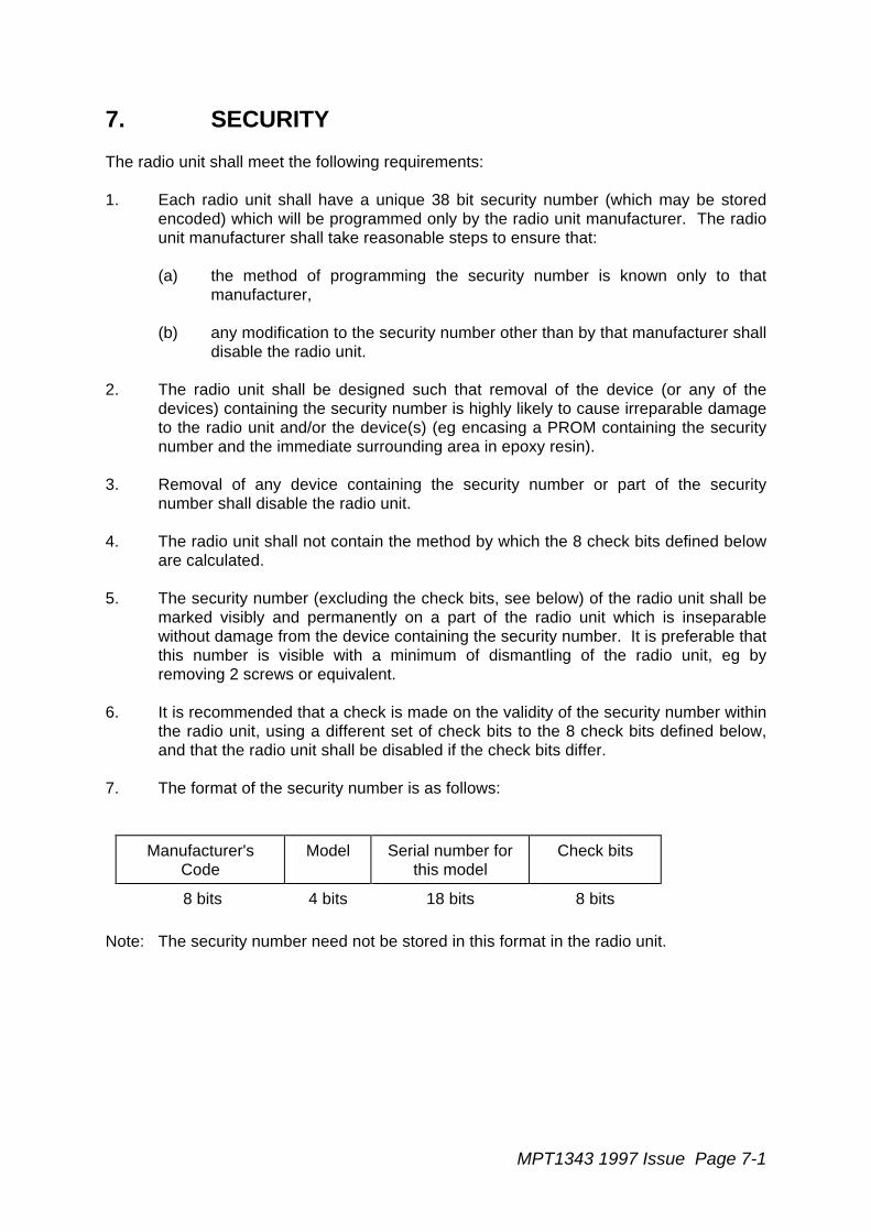
7. SECURITY
The radio unit shall meet the following requirements:
1. Each radio unit shall have a unique 38 bit security number (which may be storedencoded) which will be programmed only by the radio unit manufacturer. The radiounit manufacturer shall take reasonable steps to ensure that:
(a) the method of programming the security number is known only to thatmanufacturer,
(b) any modification to the security number other than by that manufacturer shalldisable the radio unit.
2. The radio unit shall be designed such that removal of the device (or any of thedevices) containing the security number is highly likely to cause irreparable damageto the radio unit and/or the device(s) (eg encasing a PROM containing the securitynumber and the immediate surrounding area in epoxy resin).
3. Removal of any device containing the security number or part of the securitynumber shall disable the radio unit.
4. The radio unit shall not contain the method by which the 8 check bits defined beloware calculated.
5. The security number (excluding the check bits, see below) of the radio unit shall bemarked visibly and permanently on a part of the radio unit which is inseparablewithout damage from the device containing the security number. It is preferable thatthis number is visible with a minimum of dismantling of the radio unit, eg byremoving 2 screws or equivalent.
6. It is recommended that a check is made on the validity of the security number withinthe radio unit, using a different set of check bits to the 8 check bits defined below,and that the radio unit shall be disabled if the check bits differ.
7. The format of the security number is as follows:
Manufacturer'sCode
Model Serial number forthis model
Check bits
8 bits 4 bits 18 bits 8 bits
Note: The security number need not be stored in this format in the radio unit.

Page 7-2 MPT1343 1997 Issue
8. When requested by the TSC (see section 11.15.2 and also section 15.2 ofMPT 1327), the radio unit shall send the security number data to the TSC using theSAMIS message (see MPT 1327 sections 15 and 5.6.1.2.2). The parameter fieldsof the SAMIS message are constructed as follows:
PARAMETERS 1 (20 bits) PARAMETERS 2 (18 bits)
Manufacturer'sCode
Model Check bits Serial number forthis model
8 bits 4 bits 8 bits 18 bits
Manufacturer's code: An 8 bit number (0 to 255), one or more of which is issued to eachradio unit manufacturer by the Radiocommunications Agency(RA).
Model A 4 bit number (0 to 15) which is unique to a radio unit type for agiven manufacturer's code. The model number is allocated by themanufacturer as and when new radio unit models are to be typeapproved. In the event of a radio unit manufacturer producingmore than 16 type approved models, the manufacturer may applyfor an additional manufacturer's code.
Serial number (forthis model):
The serial number of the radio unit of a given model. This numberis allocated by the manufacturer, and would normally run from 1 uptowards 262143. Where this capacity is exceeded, the radio unitmanufacturer may allocate an additional model number to radiounits of the same type approval type.
Check bits: The algorithm for calculating the check bits is based on the datacontained in the other fields above. The algorithm used in the UKis available from the Radiocommunications Agency tomanufacturers and network operators. If the check bits areincorrect in a radio unit, a network may refuse access to that radiounit. The algorithm shall not be present in the radio unit.
9.The security number shall be marked on the radio unit in the following form:
xxx/yy/zzzzzz where xxx is the manufacturer's code,yy is the model, andzzzzzz is the serial number.
eg 019/09/000129³ ³ ³³ ³ ÀÄÄÄÄ Serial number 129³ ÀÄÄÄÄÄÄÄÄÄ Model type 9ÀÄÄÄÄÄÄÄÄÄÄÄ Manufacturer number 19
10. Information about the check bits shall not be visible.

MPT1343 1997 Issue Page 7-3
11. Manufacturers codes and the security algorithm may be obtained by writing to thefollowing address:
Mobile Technology Section Radiocommunications AgencySouth Quay Three189 Marsh WallLondon E14 9SX

MPT1343 1997 Issue Page 8-1
8. MAN-MACHINE INTERFACE
8.1 Confidence Indications
8.1.1 Introduction
The user is an important element in any communications network since his behaviour cancontribute to the overall efficiency of network operation and the grade of service which canbe offered to users. Experience with telecommunications systems has shown that theprovision of appropriate indications to the user of any call or transaction using the networkto which he is a party can help to regulate user behaviour in ways which benefit systemefficiency. Indications of this type, often referred to as confidence indications, also benefitthe user and should improve user satisfaction levels.
This section of the Specification seeks to promote an acceptable and appropriate regime ofuser confidence by ensuring that users will experience a similar set of confidenceindications, especially the audible indications, no matter what manufacture of radio unit isused.
It is recognised that manufacturers of radio units will wish to exercise design independencein their products and, accordingly, the requirements of this section of the Specification havebeen kept reasonably flexible in that, though the cadences are defined for ease ofrecognition, the audible quality of the tones is not specified. Similarly the visual indicationshave not been specified and these may be, for example, steady or flashing illuminatedlegends, coloured lamps or legends displayed on alpha-numeric displays, thus giving alarge freedom of choice. Manufacturers are recommended, in the case of equipment whichis designed to be mounted in vehicles, to pay due regard to the requirements of theHighway Code and Road Safety considerations in general. In such equipment audiblesignals are often to be preferred to visual indications. Manufacturers should also bear inmind that, where visual indications are employed that may occur during speech calls, theyshould be easily visible to the user at all times during normal call operations.
The designer of each radio unit is free to design radio units to either accept or rejectincoming signalling for a new call, while the mobile is waiting for its own call to be set up.However if the radio unit accepts signalling for the new incoming call, it shall suspend theconfidence indications associated with its own call, replacing them with indications for thenew call.
When the new call is complete the suspended confidence indications shall be resumed,providing that the call waiting timer for its own call has not expired.
8.1.2 Basic Requirements
Each individual confidence indication is described in the following terms:
- Concerned Party (either CALLING or CALLED)
- Conditions to Initiate
Page 8-2 MPT1343 1997 Issue
- Conditions to Cancel
- Provision Mandatory or a Standard Option
Figure 8.1 details each indication in summary form. A more detailed description of theindications is given in the following section.
Designers of radio units should note that the use of additional indications is not prohibited.However any such additional indications shall be implemented so as to be consistent withthose detailed in this section.
The indications are not necessary if the call requires no human involvement, for exampleautomatic data messages or covert emergency calls.
Note also that an indication need not be repeated if further messages which initiate theindication are received for the transaction.
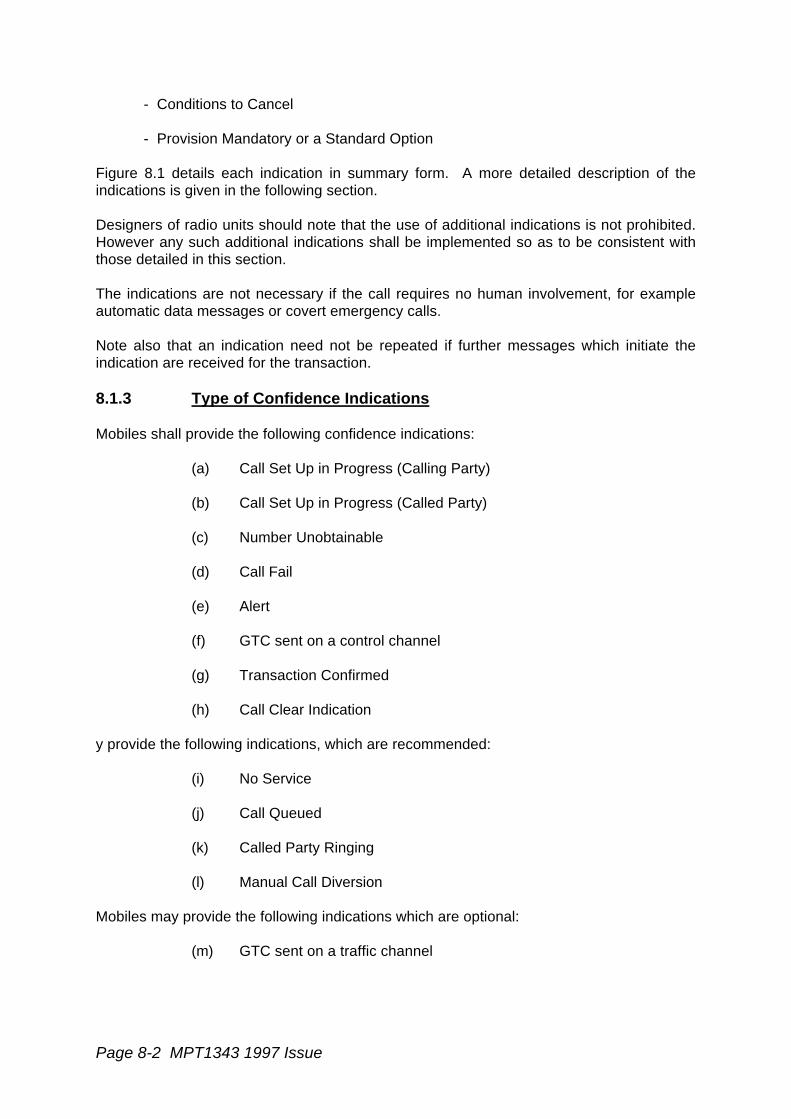
8.1.3 Type of Confidence Indications
Mobiles shall provide the following confidence indications:
(a) Call Set Up in Progress (Calling Party)
(b) Call Set Up in Progress (Called Party)
(c) Number Unobtainable
(d) Call Fail
(e) Alert
(f) GTC sent on a control channel
(g) Transaction Confirmed
(h) Call Clear Indication
y provide the following indications, which are recommended:
(i) No Service
(j) Call Queued
(k) Called Party Ringing
(l) Manual Call Diversion
Mobiles may provide the following indications which are optional:
(m) GTC sent on a traffic channel

MPT1343 1997 Issue Page 8-3
The indications shall be unambiguous with the following permitted exceptions. Indications(a) and (b) may use the same form of indication. Indications (f) and (m) may use the sameform of indication.
Audible indications shall be of the form indicated in sections 8.1.3.1 to 8.1.3.11.
Cadence Timings shall be as defined with a tolerance of ± 20% with the tone ON to toneOFF ratio controlled to within ± 20%.
The two audible tones noted in each section shall be approximately:
"Hi" - maximum frequency 1000Hz"Lo" - minimum frequency 300Hz
The "Hi" frequency shall be twice that of the "Lo" frequency ±100 Hz.
8.1.3.1. No Service
The provision of any No Service indication is optional.
8.1.3.2 Call Set Up in Progress (CSUIP)
8.1.3.2.1 CSUIP (Calling)
The provision of a CSUIP (Calling) indication is mandatory. the indication tells the user thathis call request is being processed.
CSUIP (Calling) shall commence when the calling user has completed entering the addressand call details into the unit, or on the first transmission of the request message (RQS,RQE, RQT, RQQ (not STATUS = 0 or 31 when sent with IDENT1 = TSCI)).
CSUIP (Calling) is cancelled upon receipt of any of the following messages for the call:
- ACKI (QUAL = '0'), if the unit is equipped to indicate Called Party Ringing.- ACKX- ACKV- ACK (QUAL = '0')- ACKB (QUAL = '0')- ACKT (QUAL = '0')- ACKQ, if the unit is equipped to indicate Call Queued- GTC- ACK (QUAL = '1') as a result of "User Call Set Up Abort" (sections 8.3.3.)- Expiry of the timeouts TC, TW, TJ or TI- AHYX
The audible "Lo Tone" indication shall be:
cadence 0.8s on 1.2s off.
Page 8-4 MPT1343 1997 Issue
The indication shall be cancelled as a result of "User Call Set Up Abort" (section 8.3.3.) ifno call request message has yet been sent by the radio unit.
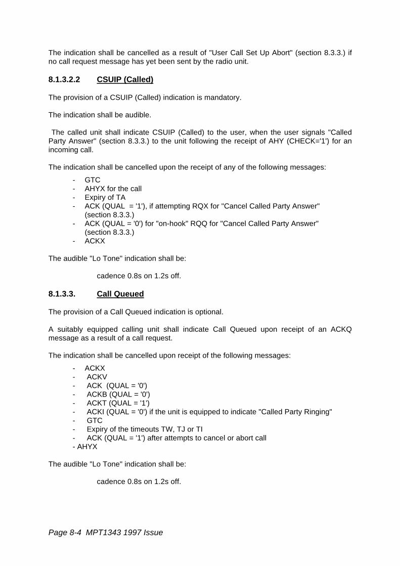
8.1.3.2.2 CSUIP (Called)
The provision of a CSUIP (Called) indication is mandatory.
The indication shall be audible.
The called unit shall indicate CSUIP (Called) to the user, when the user signals "CalledParty Answer" (section 8.3.3.) to the unit following the receipt of AHY (CHECK='1') for anincoming call.
The indication shall be cancelled upon the receipt of any of the following messages:
- GTC- AHYX for the call- Expiry of TA- ACK (QUAL = '1'), if attempting RQX for "Cancel Called Party Answer"
(section 8.3.3.)- ACK (QUAL = '0') for "on-hook" RQQ for "Cancel Called Party Answer"
(section 8.3.3.)- ACKX
The audible "Lo Tone" indication shall be:
cadence 0.8s on 1.2s off.
8.1.3.3. Call Queued
The provision of a Call Queued indication is optional.
A suitably equipped calling unit shall indicate Call Queued upon receipt of an ACKQmessage as a result of a call request.
The indication shall be cancelled upon receipt of the following messages:
- ACKX- ACKV- ACK (QUAL = '0')- ACKB (QUAL = '0')- ACKT (QUAL = '1')- ACKI (QUAL = '0') if the unit is equipped to indicate "Called Party Ringing"- GTC- Expiry of the timeouts TW, TJ or TI- ACK (QUAL = '1') after attempts to cancel or abort call- AHYX
The audible "Lo Tone" indication shall be:
cadence 0.8s on 1.2s off.
MPT1343 1997 Issue Page 8-5
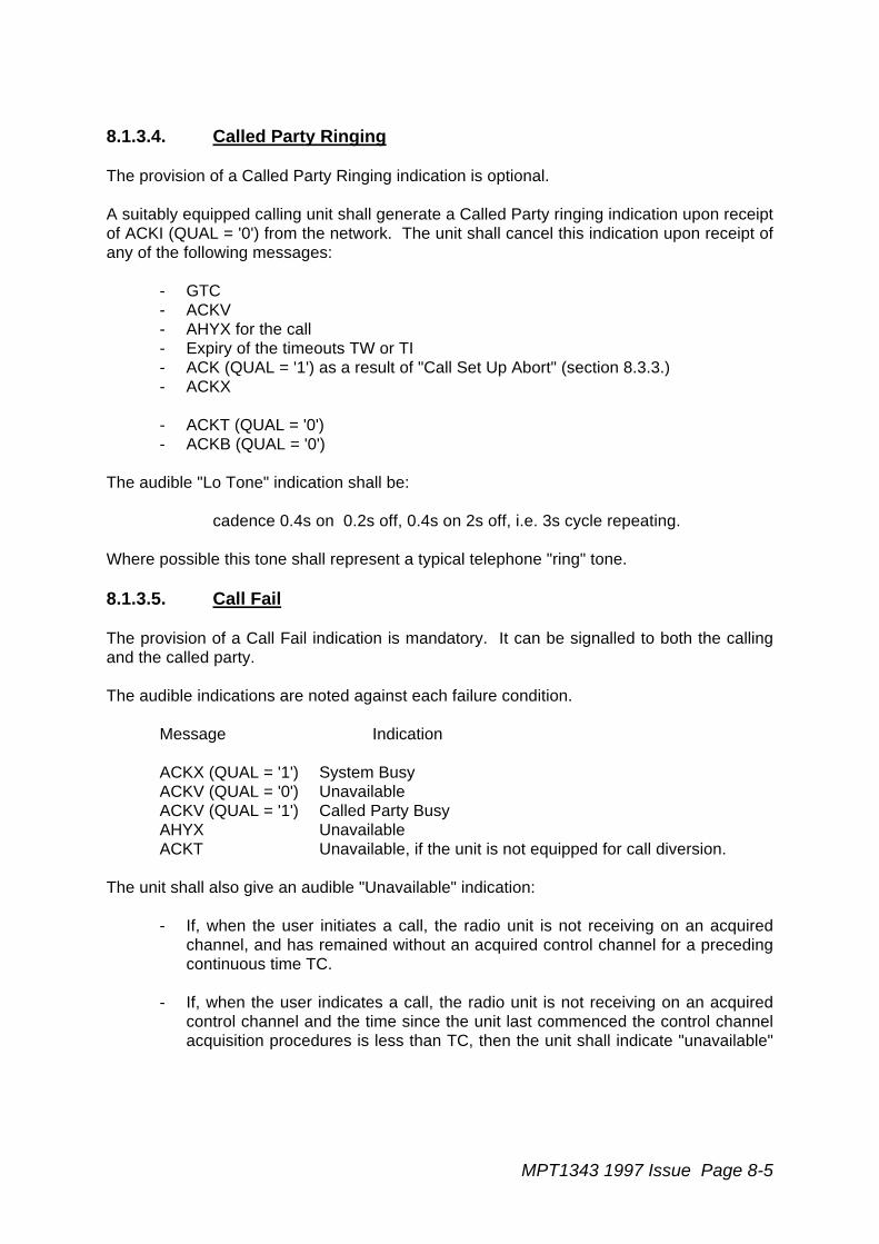
8.1.3.4. Called Party Ringing
The provision of a Called Party Ringing indication is optional.
A suitably equipped calling unit shall generate a Called Party ringing indication upon receiptof ACKI (QUAL = '0') from the network. The unit shall cancel this indication upon receipt ofany of the following messages:
- GTC- ACKV- AHYX for the call- Expiry of the timeouts TW or TI- ACK (QUAL = '1') as a result of "Call Set Up Abort" (section 8.3.3.)- ACKX
- ACKT (QUAL = '0')- ACKB (QUAL = '0')
The audible "Lo Tone" indication shall be:
cadence 0.4s on 0.2s off, 0.4s on 2s off, i.e. 3s cycle repeating.
Where possible this tone shall represent a typical telephone "ring" tone.
8.1.3.5. Call Fail
The provision of a Call Fail indication is mandatory. It can be signalled to both the callingand the called party.
The audible indications are noted against each failure condition.
Message Indication
ACKX (QUAL = '1') System BusyACKV (QUAL = '0') UnavailableACKV (QUAL = '1') Called Party BusyAHYX UnavailableACKT Unavailable, if the unit is not equipped for call diversion.
The unit shall also give an audible "Unavailable" indication:
- If, when the user initiates a call, the radio unit is not receiving on an acquiredchannel, and has remained without an acquired control channel for a precedingcontinuous time TC.
- If, when the user indicates a call, the radio unit is not receiving on an acquiredcontrol channel and the time since the unit last commenced the control channelacquisition procedures is less than TC, then the unit shall indicate "unavailable"

Page 8-6 MPT1343 1997 Issue
if it has still not acquired a control channel at a time TC after it last commencedthe control channel acquisition procedures.
- Expiry of the timeouts TA, TI, TJ or TW.
- Expiry of the timeout TC.
The audible tones shall be:
System Busy : optional, if not implemented to be replaced by "Called PartyBusy".
Audible "Lo Tone"; cadence 0.4s on, 0.35s off, 0.225s on,0.525s off, (ie 1.5 second cycle) - for 4 cycles.
Unavailable: Audible "Lo Tone"; cadence 1.5 sec duration.
Called Party Busy: Audible "Lo Tone"; cadence 0.375s on 0.375s off for 6 cycles.
The indications shall be truncated by operation of the user "Cancel Indication"(section 8.3.3).
8.1.3.6 Number Unobtainable (NU)
The provision of a NU indication is mandatory.
The calling unit shall signal NU to the user upon receipt of ACKX (QUAL = '0') in responseto a call request.
The calling unit shall also signal NU to the user when it rejects a dialled number stringwhich it does not recognise or cannot action.
The audible "Lo Tone" shall be a continuous tone of 5 seconds duration unless truncatedby operation of the user "Cancel Indication" (section 8.3.3).
8.1.3.7 Call Diversion
The provision of a call diversion indication is optional. Its purpose is to invite the callinguser to initiate a new call to a different address. The form of the indication may include thenew number which the calling users is invited to dial, or alternatively this number may bestored in the mobile without being displayed to the user.
The Call Diversion indication shall be initiated by the receipt of ACKT (QUAL = '0').
The audible tone indication shall be "Hi-Lo-Hi": cadence 0.1s on, 0.4s off, 0.1s on, 0.4s off,0.1s on, 0.4s off.
8.1.3.8 Call Clear Indication

MPT1343 1997 Issue Page 8-7
The provision of a call clear indication is mandatory. Call clear shall be indicated wheneverthe radio unit leaves a traffic channel, except when moving to a different traffic channel asdirected by a GTC message received on a traffic channel, or when moving to a differentchannel after the radio unit has received a "Call End Request" (section 8.3.3).
Audible "Hi-Lo", cadence 0.3s of each tone.
8.1.3.9 Alert
The provision of an Alert indication is mandatory.
The indication shall be audible.
Units shall indicate Alert indication if they receive AHY (POINT = 'O', CHECK='1') withIDENT2=Ident (1 to 8100), INCI, IPFIXI, PSTNGI, or PABXI and if they respond bytransmitting ACKI (QUAL = '0').
The Alert Indication shall be cancelled by user "Called Party Answer", (section 8.3.3) or bythe expiry of the Called Party Alert State timeout TA, or by receipt of an appropriate AHYXmessage.
Where the received AHY message has a zero value of the E bit, the audible "Hi Tone" shallbe cadence:
0.4s on, 0.2s off, 0.4s on, 2s off, ie. 3s cycle repeating.
Where possible this tone shall represent a typical telephone "alert" tone.
8.1.3.10 Transaction Confirmed
The provision of a Transaction Confirmed indication is mandatory.
Transaction Confirmed is used primarily in non-speech calls:
- RQC- RQT- RQQ (not STATUS=0 or 31 when sent with IDENT1 = TSCI)- Include
The radio unit shall initiate the Transaction Confirmed Indication if ACK (QUAL = '0') isreceived as a result of any of these request messages. The unit shall also initiate theTransaction Confirmed indication if ACKB (QUAL = '0') is received as a result of an RQSmessage.
The audible tone indication shall be "Lo-Hi": cadence 0.3s each tone.
8.1.3.11 GTC on Control Channel "Blip" Indication
The provision of a control channel GTC indication is mandatory.
Page 8-8 MPT1343 1997 Issue
The indication shall be at least audible.
Called radio units shall commence the GTC indication upon receipt of GTC. However if theradio unit has responded to the incoming AHY for that call with ACKI (QUAL = '0') (ie. AHYwas CHECK = '1') then the radio unit may optionally omit the GTC indication upon receiptof the GTC.
Calling radio units shall commence the GTC indication upon receipt of GTC. However if theradio unit has previously received ACKI(QUAL ='0') for the call, then the calling radio mayoptionally omit the GTC indication upon receipt of the GTC.
The GTC indication shall be implemented as a transitory indication, and its duration shall inall circumstances be less than 500 ms.
Where the incoming message for the call had a zero value of the E bit, The audible "HiTone" indication shall be 2 short "blips". Where the incoming AHY message for the call hadthe E bit set to '1', the radio unit may generate any appropriate audible tone for the GTCindication.
8.1.4 Note on use of Tone Sets
The radio unit may employ an optional tone set which differs from this specified tone set, ifrequired for specific user needs. If such a tone set is implemented it shall be as anadditional, alternative set to the one specified in this section, and its use shall be agreedby the network operator.

MPT1343 TSMG Draft and Incomplete Page 8-9
No INDICATION CALL-ING
CALL-ED
TYPE INITIATE CANCEL
1 NO SERVICE / / 0 LOSS OF CONTROL CH ACQUIRE NEWCONTROL CH
2 CSUIP (CALLING) / M
ADDRESSTERMINATOR ORTRANSMISSIONOF REQUEST
ACQUIRE NEWCONTROL CHACKX, ACKVACK(QUAL=0)ACKB(QUAL=0)ACKT(QUAL=0)ACK(QUAL=0)(IF CALLED PARTYRINGING EQUIPPEDACKQ(IF CALLQUEUED EQUIPPED)GTC, ACK(QUAL=1)EXPIRYOF TC,TW,TJ,TIAHYX CALL SET UPABORT (NOREQUEST)
3 CSUIP (CALLED) / M CALLED PARTYANSWER IF ANYWAS (CHECK=1)
GTC, AHYX,ACK(QUAL=0)ACK(QUAL=1)EXPIRY OF TAACKX
4 CALL QUEUED / O ACKQ AS No 2 LESSRECEIPT OF ACKQ
5 CALLED PARTYRINGING
/
O ACKI (QUAL=0)
GTC,ACKV,ACKX,ACKT(QUAL=0)ACKB(QUAL=0)AHYX EXPIRYOF TW OR TIACK(QUAL=1)
6 CALL FAIL / / M
ACKX (QUAL=1)ACKV,AHYXACKT(IF NO CALLDIVERSION)EXPIRYOF TW,TJ,TI,TACALL REQUEST IF NOCONTROL CHAN
CANCELINDICATION(OR INDICATIONTIMEOUT)
7 NUMBERUNOBTAINABLE
/ M ACKX(QUAL=0) ORINVALID NUMBERENTRY
CANCEL INDICATION(OR INDICATIONTIMEOUT)
8 CALL DIVERSION / O ACKT(QUAL=0) INDICATION TIMEOUT
9 CALL CLEAR / / M CLEAR INDICATION TIMEOUT
10 ALERT / M
ACKI(QUAL=0)IN RESPONSE TOAHY(CHECK=1)
AHYX,EXPIRYOF TA, CALLEDPARTY ANSWER
11 TRANSACTIONCONFIRMED
/ M
ACKI(QUAL=0)AFTER RQCRQT, OR RQQ(NOT 0 OR 31)OR INCLUDE REQUESTAND ACK B(QUAL=0)AFTER RQS
INDICATION TIMEOUT
12 GTC / / M
GTC UNLESSRESPONSE TOALERTING AHYWAS ACKI(QUAL=0) ORFOR CALLINGUNIT UNLESSACKI(QUAL=0)RECEIVED
INDICATION TIMEOUT
13 GTC ON TRAFFICCHANNEL
/ / O GTC INDICATION TIMEOUT
M = MANDATORYO = OPTIONAL
UNITCONFIDENCEINDICATION
Figure 8.1
Page 8-10 MPT1343 1997 Issue
8.2 Call Number Convention
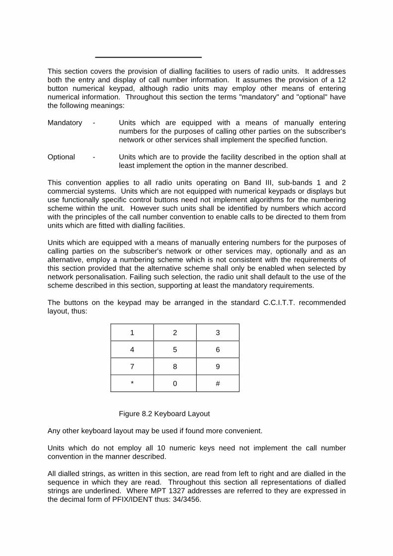
This section covers the provision of dialling facilities to users of radio units. It addressesboth the entry and display of call number information. It assumes the provision of a 12button numerical keypad, although radio units may employ other means of enteringnumerical information. Throughout this section the terms "mandatory" and "optional" havethe following meanings:
Mandatory - Units which are equipped with a means of manually enteringnumbers for the purposes of calling other parties on the subscriber'snetwork or other services shall implement the specified function.
Optional - Units which are to provide the facility described in the option shall atleast implement the option in the manner described.
This convention applies to all radio units operating on Band III, sub-bands 1 and 2commercial systems. Units which are not equipped with numerical keypads or displays butuse functionally specific control buttons need not implement algorithms for the numberingscheme within the unit. However such units shall be identified by numbers which accordwith the principles of the call number convention to enable calls to be directed to them fromunits which are fitted with dialling facilities.
Units which are equipped with a means of manually entering numbers for the purposes ofcalling parties on the subscriber's network or other services may, optionally and as analternative, employ a numbering scheme which is not consistent with the requirements ofthis section provided that the alternative scheme shall only be enabled when selected bynetwork personalisation. Failing such selection, the radio unit shall default to the use of thescheme described in this section, supporting at least the mandatory requirements.
The buttons on the keypad may be arranged in the standard C.C.I.T.T. recommendedlayout, thus:
1 2 3
4 5 6
7 8 9
* 0 #
Figure 8.2 Keyboard Layout
Any other keyboard layout may be used if found more convenient.
Units which do not employ all 10 numeric keys need not implement the call numberconvention in the manner described.
All dialled strings, as written in this section, are read from left to right and are dialled in thesequence in which they are read. Throughout this section all representations of dialledstrings are underlined. Where MPT 1327 addresses are referred to they are expressed inthe decimal form of PFIX/IDENT thus: 34/3456.

MPT1343 1997 Issue Page 8-11
The primary use for the keypad is to enable the user to originate speech calls from theradio unit. Calls may be made to other units operating on the network, to extensions onuser associated private automatic branch exchanges (PABX) and to subscribers on thepublic switched telephone network (PSTN). Other services may be added as required.
Codes which commence with an asterisk (*) or a number sign (#) provide secondary usesfor the keypad. Functions such as the modification of call requests to originate statusmessages, and the implementation of other MPT 1327 facilities (data, diversion, etc), arecontrolled in this manner.
Control of the radio unit's internal functions which affect MPT 1327 related activities alsoemploy similar codes.
Any facility requested by means covered in this section which is not a mandatoryrequirement of Section 11 need not be incorporated into such a unit. For units which havea numerical keypad any facility which is incorporated into the unit shall be implemented inthe manner described in this section. As an option it may be possible to bar access to anycall type other than in-fleet calls.
Other uses of the keypad are not prohibited as long as no conflict occurs with the specifieduse. All dialled strings which the unit does not recognise shall result in the unit rejecting thedialled string and signalling the rejection with a number unobtainable indication (see section8.1).
8.2.1 Network Numbering Structure
Each unit is allocated an individual network number (unique within the network to which theuser subscribes) which bears a fixed relationship with an MPT 1327 address. The networknumber is in three parts: a number prefix, a fleet number and a unit number. Groups ofunits are allocated a network group number in a similar manner. A unit may be allocated tomore than one group and thus may respond to more than one group number.
A 20 bit MPT 1327 address is divided into a prefix and an identity. The prefix is the first 7bits of the 20 bit address. The identity is the remaining 13 bits. Fleet organisation shallensure that most calls between users are made between those who share the same prefix.The identity range is divided into blocks which are allocated to fleets by the networkoperator. Each fleet user shall be allocated an adequate number of identities to allow forreasonable expansion requirements.
The objective of the scheme is to enable a short dialled string to be used for the moreregularly used numbers instead of the long dialled string that the direct decimalrepresentation of the binary prefix and identity would entail. Once this primary objectivehas been attained the secondary objective of permitting access to other speech and dataservices completes the scheme. The scheme is expandable to allow the introduction ofadditional services in the future.
In-fleet individual calls are implemented by allocating a starting number (20 or 200depending on fleet size) to the lowest identity which is allocated to the fleet. The lowestidentity (base ID) used by the fleet for individual calls shall be retained within each radiounit as part of the unit's fleet personality. All units in the fleet are allocated numbers whichincrement in step with their allocated identities.
Page 8-12 MPT1343 1997 Issue
In-fleet group calls are similarly implemented by allocating a starting number (in this case90 or 900 depending on fleet size) to the lowest fleet identity. The lowest identity (base ID)used by the fleet for group calls shall be retained within each radio unit as part of the unit'sfleet personality.
In-fleet numbering schemes are thus related to allocated identities by means of analgorithm.
PABX calls also employ an offset to ensure that maximum use is made of the MPT 1327addressing range of 0 to 8191 when sending extension numbers. As the lowest value ofextension number in a four digit numbering scheme will not be less than 1000, all dialledstrings are reduced in value by 1000 before transmission. This ensures that numbers up to8999 may be transmitted in a single codeword call.
Calls require the use of the extended addressing facility when PABX extension numbers, orrouting codes plus extension numbers, have five or more digits. If 7, 8 or 0 are used asleading digits within the PABX network then the same network dialling strings may beemployed with the radio unit. If other leading digits are used within the PABX network thenthe most reasonable choice of leading digit from 7, 8 or 0 may be used for PABX access,with appropriate action being taken at the radio network/PABX interface point to ensurethat the correct string is offered to the PABX to ensure proper call routing.
PSTN calls are made either by using abbreviated addressing with TSC translation or byentering the full national number. The leading zero of the called number is redundant andis not transmitted to the TSC. This allows all national numbers to be contained within oneSAMIS.
8.2.2 Philosophy
8.2.2.1 Relationship with Address
The numerical digits which are dialled by the user are translated into an MPT 1327specified address. This is transmitted in an address codeword with, if necessary, additionaldate codewords.
Use is made of MPT 1327 flags and addresses to send relevant signalling informationbetween the radio unit and the TSC as part of the call set-up procedure. Dialled stringlength is an integral part of the scheme. The length of the dialled string and the leadingdigit indicate the service which the calling party requires and are both used to set therelevant flags and addresses in the address codeword.
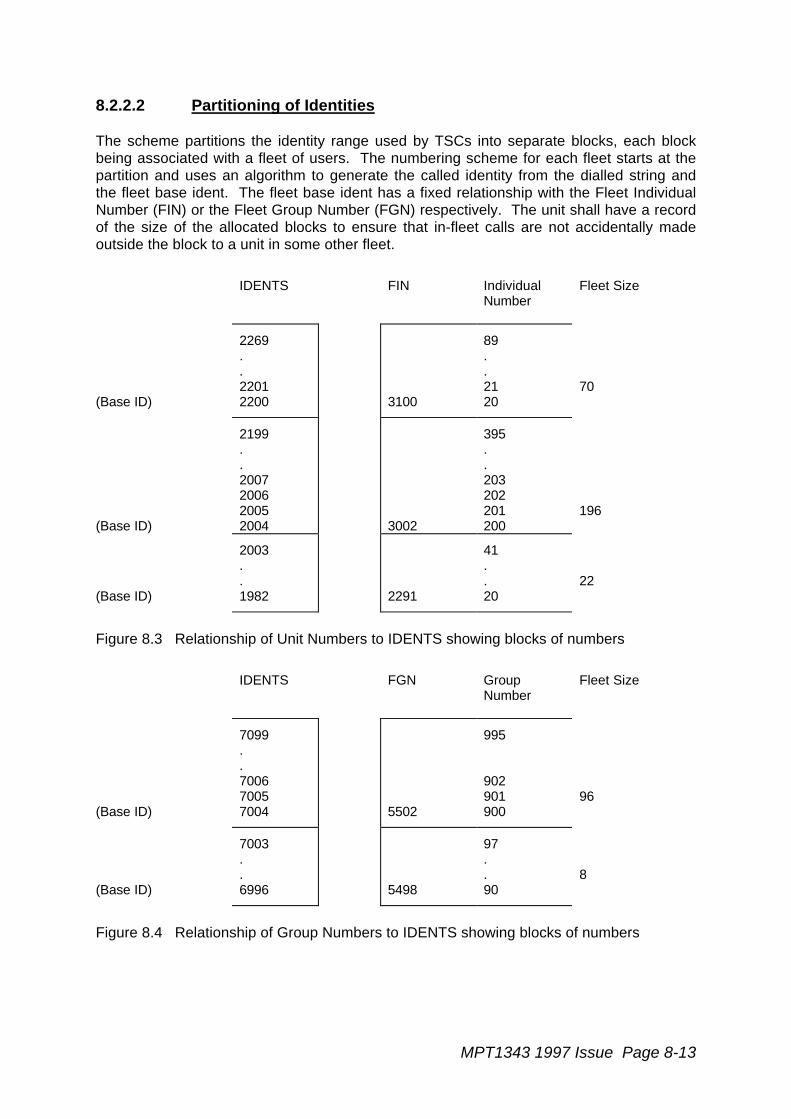
MPT1343 1997 Issue Page 8-13
8.2.2.2 Partitioning of Identities
The scheme partitions the identity range used by TSCs into separate blocks, each blockbeing associated with a fleet of users. The numbering scheme for each fleet starts at thepartition and uses an algorithm to generate the called identity from the dialled string andthe fleet base ident. The fleet base ident has a fixed relationship with the Fleet IndividualNumber (FIN) or the Fleet Group Number (FGN) respectively. The unit shall have a recordof the size of the allocated blocks to ensure that in-fleet calls are not accidentally madeoutside the block to a unit in some other fleet.
IDENTS FIN IndividualNumber
Fleet Size
(Base ID)
2269..22012200 3100
89..2120
70
(Base ID)
2199..2007200620052004 3002
395..203202201200
196
(Base ID)
2003..1982 2291
41..20
22
Figure 8.3 Relationship of Unit Numbers to IDENTS showing blocks of numbers
IDENTS FGN GroupNumber
Fleet Size
(Base ID)
7099..700670057004 5502
995
902901900
96
(Base ID)
7003..6996 5498
97..90
8
Figure 8.4 Relationship of Group Numbers to IDENTS showing blocks of numbers

Page 8-14 MPT1343 1997 Issue
8.2.2.3 Method of Dialling
Pre-origination dialling is used in the radio units. The user indicates completion of entriesby the use of the # key. When it is necessary to modify the function of the call set-up,though not the destination, call modifiers may be dialled before the called party number.Modifiers are separated from the called number by use of the * key. See section 8.2.8.
8.2.2.4 User Familiarity
To make the scheme familiar to the user, the numbering scheme attempts to follow normalUK telephony practice in the allocation of numbers. Thus:
- PSTN access commences with 0 and used dialled strings of 8 or more digits; thecalled subscriber's full national number is dialled,
- network operator services start with a leading 1 and are three digits in length,
- PABX operators may be obtained with a single 0
- Local PABX numbering schemes, four digits, with the leading digit in the range 1to 8,
- PABX network numbering schemes, dialled strings to 5 to 7 digits, with leadingdigits 0, 7 and 8,
- PABX network numbering schemes, dialled strings of 8 and 9 digits, with leadingdigits 7 and 8.
To accommodate the above, dialled strings for calls to radio units have the followingconstraints:
- the number prefix leading digit is 2 or 3 (dialled strings of 9 and 10 digits),
- the fleet number leading digit is in the range 2 to 6 (dialled strings of 6 and 7digits),
- the unit number leading digit is in the range 2 to 8 (dialled strings of 2 and 3digits).
8.2.2.5 Types of Access
The numbering scheme accommodates at least:
- Members of the same fleet - Members of other fleets
- Members of other fleets with - PABX extensions associateda different prefix with the user's fleet
- Access to nominated PSTN - Full access to PSTN subscriberssubscribers
- Network operator services - Data services (to be defined)
8.2.2.6 Use of Display
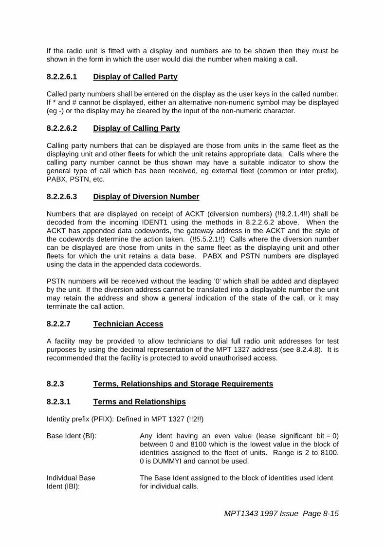
MPT1343 1997 Issue Page 8-15
If the radio unit is fitted with a display and numbers are to be shown then they must beshown in the form in which the user would dial the number when making a call.
8.2.2.6.1 Display of Called Party
Called party numbers shall be entered on the display as the user keys in the called number.If * and # cannot be displayed, either an alternative non-numeric symbol may be displayed(eg -) or the display may be cleared by the input of the non-numeric character.
8.2.2.6.2 Display of Calling Party
Calling party numbers that can be displayed are those from units in the same fleet as thedisplaying unit and other fleets for which the unit retains appropriate data. Calls where thecalling party number cannot be thus shown may have a suitable indicator to show thegeneral type of call which has been received, eg external fleet (common or inter prefix),PABX, PSTN, etc.
8.2.2.6.3 Display of Diversion Number
Numbers that are displayed on receipt of ACKT (diversion numbers) (!!9.2.1.4!!) shall bedecoded from the incoming IDENT1 using the methods in 8.2.2.6.2 above. When theACKT has appended data codewords, the gateway address in the ACKT and the style ofthe codewords determine the action taken. (!!5.5.2.1!!) Calls where the diversion numbercan be displayed are those from units in the same fleet as the displaying unit and otherfleets for which the unit retains a data base. PABX and PSTN numbers are displayedusing the data in the appended data codewords.
PSTN numbers will be received without the leading '0' which shall be added and displayedby the unit. If the diversion address cannot be translated into a displayable number the unitmay retain the address and show a general indication of the state of the call, or it mayterminate the call action.
8.2.2.7 Technician Access
A facility may be provided to allow technicians to dial full radio unit addresses for testpurposes by using the decimal representation of the MPT 1327 address (see 8.2.4.8). It isrecommended that the facility is protected to avoid unauthorised access.
8.2.3 Terms, Relationships and Storage Requirements
8.2.3.1 Terms and Relationships
Identity prefix (PFIX): Defined in MPT 1327 (!!2!!)
Base Ident (BI): Any ident having an even value (lease significant bit = 0)between 0 and 8100 which is the lowest value in the block ofidentities assigned to the fleet of units. Range is 2 to 8100.0 is DUMMYI and cannot be used.
Individual Base The Base Ident assigned to the block of identities used IdentIdent (IBI): for individual calls.
Page 8-16 MPT1343 1997 Issue
Group Base Ident (GBI): The Base Ident assigned to the block of identities used forgroup calls.
Number Prefix (NP): NP = PFIX + 200. Range is 200 to 327.
Fleet Number (FN): FN = BI/2 + 2000, where BI is the lowest ident in the blockallocated to the fleet. Range is 2001 to 6050. The networkoperator may restrict the range for his own purposes.
Fleet IndividualNumber (FIN): An FN which identifies a block of Unit Numbers.
Unit Number (UN): The Unit Number consists of either two or three digitsdepending on the fleet size and is unique to one unit in anysingle fleet.
2 digit: UN = Unit individual identity - IBI + 20Numbering range: 20 to 89 (fleet size up to and including 70).
3 digit: UN = Unit individual identity - IBI + 200Numbering range: 200 to 899 (fleet size up to and including700).
Fleet Group Number(FGN): An FN which identifies a block of Group Numbers.
Group Number (GN): The Group Number consists of either two or three digitsdepending on the fleet size and is allocated to units whichhave common interests.
2 digit: GN = Group identity - GBI + 90Numbering range: 90 to 99
3 digit: GN = Group identity - GBI + 900Numbering range: 900 to 998 (999 reserved for emergencyservice).
Block Size: The size of the block allocation to a fleet of users for eachform of Base Ident used by the members of the fleet. The unitshall store either block size or the maximum value of diallednumber in some form to avoid placing calls outside the block.
Numbers shall be written in the form:
NP FIN UN for individual numbers
e.g. 245201
34563578
23467
NP FGN GN for group numbers

MPT1343 1997 Issue Page 8-17
e.g. 245201
54565578
93967
Numbers are dialled commencing at the most significant block of numbers which differsfrom the unit's own number.
8.2.3.2 Storage Requirements
8.2.3.2.1 Mandatory Storage Requirements
In order to follow the procedures specified in this section, the radio unit shall provide thefollowing storage requirements (in read-only memory) which are appropriate to the selectednetwork if the unit is equipped with a means of accepting called party numbers from theuser:
i. The individual base identity for the fleet of which the unit is a member (own fleet).
ii. The group base identity for the unit's own fleet.
iii. A flag to indicate the choice of own fleet individual number string length, ie 2 or 3digit strings.
iv. A flag to indicate the choice of own fleet group number string length, ie 2 or 3 digitstrings.
v. The highest permitted own fleet individual identity or dialled number.
vi. The highest permitted own fleet group identity or dialled number.
vii. A flag to bar inter-fleet group calls.
8.2.3.2.2 Optional Storage Requirements in read-only memory
i. Ten actual called party identities or numbers for translation. Each is associated withan entry of one of the single digit dialled strings.
ii. A multiplicity of i) to vi) in 8.2.3.2.1 above per fleet, each stored against the two orthree leading digits of the five digit calls to units in other fleets.
iii. An address or number to complete call details for the *0# string.
iv. An address or number to complete call details for the *0nn# string.
v. An address or number to complete call details for the *9# string.
8.2.4 Radio Unit and Line Unit Numbering
8.2.4.1 Single Digit Dialled Strings (Optional)
The translation between single digit dialled strings and corresponding identities is notspecified. It is recommended that 0 be used either for calls to a despatcher or to a PABXoperator (see 8.2.5).
Page 8-18 MPT1343 1997 Issue
8.2.4.2 Two Digit Dialled Strings (Mandatory)
Two digit dialled strings in the range 20 to 89 inclusive shall be used to call units within thesame fleet. The unit shall refer to its individual base ident (IBI) and shall generate thecalled party identity by the following algorithm from the dialled Unit Number (UN):
Called individual ident = IBI + UN - 20
Two digit dialled strings in the range 90 to 99 inclusive shall be used to call groups of unitswithin the same fleet. The unit shall refer to its group base ident (GBI) and shall generatethe called group identity by the following algorithm from the dialled Group Number (GN):
Called group ident = GBI + GN - 90
Two digit group numbers and three digit unit numbers may be used within the same fleet.
The unit shall verify that the dialled UN or GN is not greater than the highest valueassigned during network personalisation.
Note: Numbers 00 to 02, 07 to 09 and 10 to 19 are not specified. For use of 03 to06, see section 8.2.5.
8.2.4.3 Three Digit Dialled Strings (Mandatory)
Three digit dialled strings in the range 200 to 899 inclusive shall be used to call units withinthe same fleet. The unit shall refer to its individual base ident (IBI) and shall generate thecalled party identity by the following algorithm from the dialled Unit Number (UN):
Called individual ident = IBI + UN - 200
Three digit dialled strings in the range 900 to 998 inclusive shall be used to call groups ofunits within the same fleet. The unit shall refer to its group base ident (GBI) and shallgenerate the called group identity by the following algorithm from the dialled Group Number(GN):
Called group ident = GBI + GN - 900
Three digit group numbers and two digit unit numbers may be used within the same fleet.
The unit shall verify that the dialled UN or GN is not greater than the highest valueassigned during network personalisation.
Note: Numbers 000 to 099 are not specified. Certain numbers in the range 100 to199 and also 999 are used for calls to assistance operators (optional - seesection 8.2.7).
8.2.4.4 Four Digit Dialled Strings (Optional)
Four digit dialled strings in the range 1000 to 8999 are used for PABX access, see 8.2.5.Other four digit dialled strings are not specified.
MPT1343 1997 Issue Page 8-19
8.2.4.5 Five Digit Dialled Strings. Leading Digit 2 or 9 (Optional)
Five digit dialled strings with leading 2 or 9 may be used to make inter-fleet calls toindividual units or groups of units. If both types of call are to be made then the conventionof using 2 for individual calls and 9 for group calls shall be adopted wherever possible.Dialled string manipulation depends upon the length of the called party unit number. Thefirst part of the dialled string forms a "routing code" which identifies the fleet of which thecalled unit is a member. If the called unit number is 2 digits in length then the code is 3digits in length. If the called unit number is 3 digits in length then the code is 2 digits inlength. The unit shall contain a look-up table (translation field) in which the "routing code"is converted to the FN (or its equivalent address) which is appropriate to the called unit.The table shall also contain data on the partition point between the "routing code" and theunit number and whether the call is to a group address. This latter data shall be usedbefore accepting a command to set RQS or RQE, FLAG1 = '1' in a group call.
eg for a call to an individual unit (RC UN): 28 789#
28 is translated by the unit, for example, to fleet Base Address: 34/936
The prefix is used directly and the called IDENT, 1525, is calculated by using the algorithm:
ID = IBI - 200 + UN
1525 = 936 - 200 + 789
Either a common prefix call or an extended addressing call follows appropriately.
For a call to a group (RC GN): 984 98#
984 is translated, for example, to Fleet Group Base Address: 34/5936
The prefix is used directly and the called IDENT, 5944, is calculated by using the algorithm:
ID = GBI - 90 + GN
5944 = 5936 - 90 + 98
Either a common prefix call or an extended addressing call follows appropriately.
Note: Dialled strings of this length commencing with 1 are not specified. Dialledstrings commencing with digits 3, 4, 5, 6, 7, 8 and 0 are used for PABX calls.
8.2.4.6 Six Digit Dialled Strings. Leading Digit 2 to 6 (Mandatory)
A six digit dialled string with a leading digit in the range 2 to 6 shall be used for inter-fleetcalls where the call is between units having a common prefix. The first four digits are thecalled party fleet number (FN) from which the unit shall create a base identity.
BI = 2(FN - 2000)
Using the created base identity and the rest of the dialled string as a unit number (UN) theunit creates a common prefix call using the procedures specified in 8.2.4.2.

Page 8-20 MPT1343 1997 Issue
Called individual ident = BI + UN - 20
Group calls, which are identifiable by 9 in the fifth digit, are handled similarly.
Called group ident = BI + GN - 90
It shall be possible to suppress inter-fleet group calls by unit personalisation.
Note: Dialled strings of this length commencing with 0, 7 and 8 are used for PABXcalls. Those commencing with 1 are not specified.
8.2.4.7 Seven Digit Dialled Strings. Leading Digit 2 to 6 (Mandatory)
A seven digit dialled string with a leading digit in the range 2 to 6 shall be used for inter-fleet calls where the call is between units having a common prefix. The first four digits arethe called party fleet number (FN) from which the unit shall create a base identity.
BI = 2 (FN - 2000)
Using the created base identity and the rest of the dialled string as a unit number (UN) theunit creates a common prefix call using the procedures specified in 8.2.4.3.
Called individual ident = BI + UN - 200
Group calls, which are identifiable by 9 in the fifth digit, are handled similarly.
Called group ident = BI + GN - 900
It shall be possible to suppress inter-fleet group calls by unit personalisation.
Note: Dialled strings of this length commencing with 0, 7 and 8 are used for PABXcalls. Those commencing with 1 are not specified.
8.2.4.8 Eight Digit Dialled Strings. Leading Digit 1 (Technician facility -Optional)
When the technician facility is enabled then 8 digit dialled strings with a leading 1, digits 2to 4 in the range 000 to 127 and digits 5 to 8 in the range 0001 to 8100, shall set up a callto an address of which the last seven digits in the dialled string are the decimalrepresentation.
The dialled string shall be of the form:
1 PFIX IDENTe.g. 1 012 0246
The unit shall translate the dialled decimal representations of the prefix and identity intotheir binary equivalents and use these to transmit a single address codeword or extendedaddressing call request, whichever is appropriate to the radio unit's own address.
MPT1343 1997 Issue Page 8-21
Note that although addresses are written in the form 12/246, the leading zeros shall bedialled thus: 012 0246. Idents above 8100 shall be blocked to prevent calls to gatewayaddresses which may cause potential fault conditions.
Note: Dialled strings of this length commencing with 0 are used for PSTN calls.Dialled strings with other leading digits are not specified.
8.2.4.9 Nine Digit Dialled Strings. Leading Digit 2 or 3 (Mandatory)
A nine digit dialled string with leading digits 2 or 3 shall be used for inter-fleet calls wherethe call is between units having different prefixes. the first three digits are the called party'sNumber Prefix (NP), from which the unit shall create a prefix (PFIX).
PFIX = NP - 200
The rest of the dialled string shall be manipulated as specified in 8.2.4.6. An extendedaddressing call shall be made to IPFIXI and the unit shall respond to an AHYC with aSAMIS containing the called party's address (!!9.2.2.1!!). The unit shall trap the NumberPrefix if it corresponds to the unit's own Number Prefix and shall resort to a common prefix,single address codeword call.
Note: Dialled strings of this length commencing with 0 are used for PSTN calls.Dialled strings with other leading digits are not specified.
8.2.4.10 Ten Digit Dialled Strings. Leading Digit 2 or 3 (Mandatory)
A ten digit dialled string with leading digits 2 or 3 shall be used for inter-fleet calls where thecall is between units having different prefixes. The first three digits are the called party'sNumber Prefix (NP), from which the unit shall create a prefix (PFIX).
PFIX = NP - 200
The rest of the dialled string shall be manipulated as specified in 8.2.4.7. An extendedaddressing call shall be made to IPFIXI and the unit shall respond to an AHYC with aSAMIS containing the called party's address (!!9.2.2.1!!). The unit shall trap the NumberPrefix if it corresponds to the unit's own Number Prefix and shall resort to a common prefix,single address codeword call.
Note: Dialled strings of this length commencing with 0 are used for PSTN calls.Dialled strings with other leading digits are not specified.
8.2.5 PABX Numbering (Optional)
MPT 1327 allows the radio unit to transmit numbers between 0 and 8191 with EXT = '1' inan RQS or RQE single address codeword call, in order to indicate that the called identity isan extension number of a PABX which is associated with the radio unit caller (!!5.5.3.1.1!!).FLAG1 and FLAG2 are used to select one from a maximum of four PABXs. The TSCforwards the dialled number to the selected PABX. Extended addressing procedures arerequired via the PABXI gateway for calls to extensions on exchanges employing five ormore digits, or to larger PABX networks.
Page 8-22 MPT1343 1997 Issue
Most PABXs use fixed length dialled strings whose leading digit is equal to or greater than1. Thus the largest range of numbers which may be encountered and which can beaccommodated in a single address codeword call is 1000 to 8999. However this rangemay only be accommodated by interposing an off-set in the transmitted request from thecalling unit. This off-set is removed by the TSC. The off-set is 1000; thus for dialledextension numbers (EXTN) in the range 1000 to 8999 the unit sends 0 to 7999 in IDENT1.
IDENT1 = EXTN - 1000
Calls to PABXs with dialled strings shorter than four digits shall have dummy digits insertedin the leading digit positions (to be described as a dialling code in the user's directory) tomake up the length of the dialled string to four digits. Recommended values are 7, 77, etc.Different codes may be used to route calls to different branch exchanges by arrangementbetween the network operator and the PABX user. Shorter dialled strings on PABXs withmixed length numbering shall be dealt with in a similar manner.
If access is required to a small group of branch exchanges (a maximum of four), thenFLAG1 and FLAG2 in the RQS or RQE address codeword shall be set to indicate to whichexchange the required extension is connected. The flags are set in the radio unit by theuse of a leading digit before the extension number, which thus requires the user to dial afive digit string.
Access to larger PABX networks uses extended addressing routines. These are set up bydialled string lengths of five to eight digits and with particular leading digits.
8.2.5.1 Single digit Dialled Strings
To call a PABX operator the unit may be set up to call identity 8000 with EXT = '1',FLAG='0' and FLAG2 = '0' when 0 is dialled.
8.2.5.2 Two Digit Dialled Strings
A two digit dialled string in the range 03 to 06 shall be used to select one of four differentbranch exchange operators. The radio unit shall be set up to call identity 8000 with EXT ='1', and FLAG1 and FLAG2 set according to the following table:
FLAG1 FLAG2
03 '0' '0'04 '0' '1'05 '1' '0'06 '1' '1'
8.2.5.3 Three Digit Dialled Strings
Three digit dialled strings are not used for PABX calls.
8.2.5.4 Four Digit Dialled Strings
The radio unit shall accept any four digit dialled string as a call to a PABX and shall set theEXT flag to '1'. FLAG1 and FLAG2 shall be set to '0'. The dialled extension number
MPT1343 1997 Issue Page 8-23
(EXTN) shall be decremented by 1000 and the resultant shall be transmitted as the calledidentity (see 8.2.5).
IDENT = EXTN - 1000
8.2.5.5 Five Digit Dialled Strings. Leading Digit 3 to 6
Five digit dialled strings with a leading digit from 3 to 6 function similarly to four digit dialledstrings, but the radio unit shall set FLAG1 and FLAG2 in RQS or RQE, or EXCHANGE inSAMIS, according to the following table:
Leading Digit FLAG1 FLAG2 EXCHANGE (SAMIS)!!5.5.3.1.1!! !!5.6.1.2.2!!
3 '0' '0' '00'4 '0' '1' '01'5 '1' '0' '10'6 '1' '1' '11'
Having used the leading digit in the five digit dialled string to set FLAG1 and FLAG2, theradio unit shall process the remaining four digits as described in 8.2.5.4.
8.2.5.6 Five to Seven Digit Dialled Strings. Leading Digits 0, 7 or 8
Dialled strings of five to seven digits with leading digits 0, 7 or 8 shall be used to send a callto the PABXI gateway. On receipt of a Mode 1 AHYC with IDENT1 = PABXI and DESC ='010', the radio unit shall respond with a SAMIS containing DESC = '010', and with the fulldialled string occupying BCD blocks commencing with BCD1. Unused blocks shall be filledwith NULL.
Note: Five digit dialled strings with leading 2 or 9 are used for inter-fleet calls andleading digit 1 is not specified.,
8.2.5.7 Eight or Nine Digit Dialled Strings. Leading Digits 7 or 8
Dialled strings of eight or nine digits with leading digits 7 or 8 shall cause the radio unit tosend a call to the PABXI gateway. On receipt of a Mode 1 AHYC with IDENT1 = PABXIand DESC = '010', the radio unit shall respond with a SAMIS containing DESC = '010' andwith the full dialled string occupying BCD blocks commencing with BCD1. When the dialledstring length is 8 digits the unused block shall be filled with NULL.
8.2.6 PSTN Numbering (Optional)
8.2.6.1 PSTN Abbreviated Dialling
Single address codeword calls and diversions may be made to 15 pre-arranged numbersby using the special idents PSTNSIj. The procedures are defined in section 8.2.8.1.
8.2.6.2 Calls to PSTN Subscribers
Dialled strings of eight or more digits with leading digit 0 shall cause the radio unit to sendan RQS or RQE call to the PSTNGI gateway with FLAG1 set to '0' to indicate a dialled
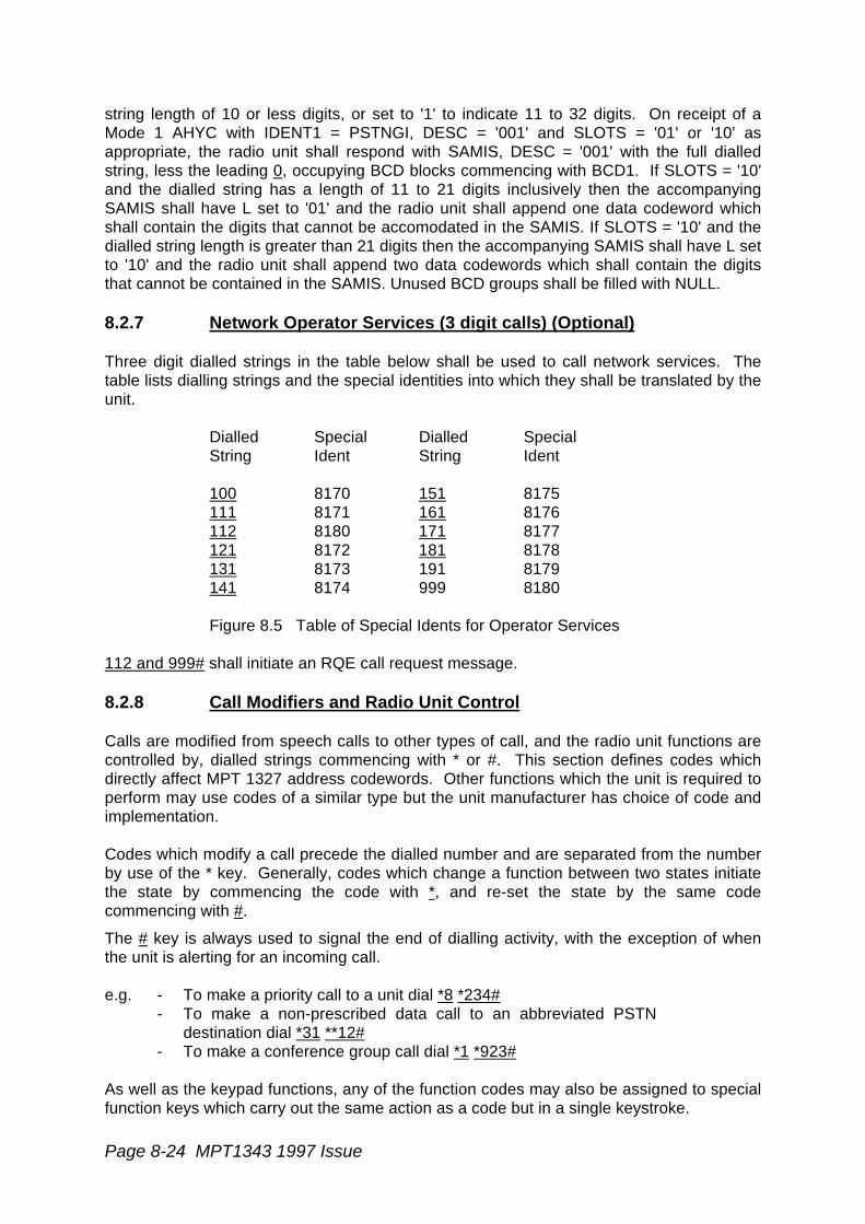
Page 8-24 MPT1343 1997 Issue
string length of 10 or less digits, or set to '1' to indicate 11 to 32 digits. On receipt of aMode 1 AHYC with IDENT1 = PSTNGI, DESC = '001' and SLOTS = '01' or '10' asappropriate, the radio unit shall respond with SAMIS, DESC = '001' with the full dialledstring, less the leading 0, occupying BCD blocks commencing with BCD1. If SLOTS = '10'and the dialled string has a length of 11 to 21 digits inclusively then the accompanyingSAMIS shall have L set to '01' and the radio unit shall append one data codeword whichshall contain the digits that cannot be accomodated in the SAMIS. If SLOTS = '10' and thedialled string length is greater than 21 digits then the accompanying SAMIS shall have L setto '10' and the radio unit shall append two data codewords which shall contain the digitsthat cannot be contained in the SAMIS. Unused BCD groups shall be filled with NULL.
8.2.7 Network Operator Services (3 digit calls) (Optional)
Three digit dialled strings in the table below shall be used to call network services. Thetable lists dialling strings and the special identities into which they shall be translated by theunit.
Dialled Special Dialled SpecialString Ident String Ident
100 8170 151 8175111 8171 161 8176112 8180 171 8177121 8172 181 8178131 8173 191 8179141 8174 999 8180
Figure 8.5 Table of Special Idents for Operator Services
112 and 999# shall initiate an RQE call request message.
8.2.8 Call Modifiers and Radio Unit Control
Calls are modified from speech calls to other types of call, and the radio unit functions arecontrolled by, dialled strings commencing with * or #. This section defines codes whichdirectly affect MPT 1327 address codewords. Other functions which the unit is required toperform may use codes of a similar type but the unit manufacturer has choice of code andimplementation.
Codes which modify a call precede the dialled number and are separated from the numberby use of the * key. Generally, codes which change a function between two states initiatethe state by commencing the code with *, and re-set the state by the same codecommencing with #.
The # key is always used to signal the end of dialling activity, with the exception of whenthe unit is alerting for an incoming call.
e.g. - To make a priority call to a unit dial *8 *234#- To make a non-prescribed data call to an abbreviated PSTN
destination dial *31 **12#- To make a conference group call dial *1 *923#
As well as the keypad functions, any of the function codes may also be assigned to specialfunction keys which carry out the same action as a code but in a single keystroke.

MPT1343 1997 Issue Page 8-25
8.2.8.1 Call Initiation
8.2.8.1.1 Abbreviated Dialling (Optional)
Codes for TSC translation of special idents shall be of the form:
**nn#
nn shall be in the range 1 to an upper limit specified by the network operator, but notgreater than 49. nn shall be translated by the radio unit into a special ident by the followingalgorithm:
Ident = 8120 + nn
8.2.8.1.2 Call ALLI: Codes *1981# to *1987# (Optional)
The entry of any of the codes *1981# to *1987# may be used to cause the radio unit tosend RQS, RQE or RQC (as specified below) with IDENT1 set to the special ident 8191(the system-wide ident - refer to !!4!!). The type of request message to be sent and thevalues of certain fields within that message shall depend upon the value of the codeentered, as specified below:
Code Type of System- Request Message Specified Fieldwide Call Type Value
*1981# Priority voice RQS DT='0' LEVEL='0'*1982# Emergency voice RQE DT='0'*1893# Priority np data RQS DT='1' LEVEL='0'*1984# Emergency np data RQE DT='1'*1985# Short data RQC*1987# Standard voice RQS DT='0' LEVEL='1'
The above codes may not be used in conjunction with any additional digits (eg other callmodifiers or destination digit strings).
8.2.8.2 Call Modifiers (Optional)
8.2.8.2.1 Despatcher and Status calls
Enter Despatcher Queue: Code *0
The radio unit shall set up an RQQ (STATUS = 0) call to the dialled number. The radio unitmay default to a pre-arranged number if a number is not dialled, ie the unit may set up anRQQ call to an address which is programmed within the unit if the # key is depressedimmediately after the code (!!5.5.3.1.7!!).
Leave Despatcher Queue: Code #0
The radio unit shall set up an RQQ (STATUS = '31') call to the dialled number. The radiounit may default to the last despatcher queue which had been entered if no number isdialled (!!5.5.3.1.7!!).
Page 8-26 MPT1343 1997 Issue
Send Status: Code *0nn
The radio unit shall set up an RQQ (STATUS = 'nn') call to the dialled number. The radiounit may default to a pre-arranged number if a number is not dialled, ie the unit may set upan RQQ call to an address which is programmed within the unit if the # key is depressedimmediately after the code. nn is a single or two digit code without a leading zero and shallbe in the range 1 to 30 (!!5.5.3.1.7!!).
8.2.8.2.2 Conference/Broadcast Group Facility
Units which receive group calls may allow the user to reply to the calling party (conference)or the unit may inhibit replies (broadcast) on receipt of a maintenance message on thetraffic channel. The unit originating the call sends RQS (FLAG1 = '1') or RQE (FLAG1 = '1')to disable the called units' ability to reply. The calling unit shall only set FLAG1 to '1' if thecalled address is a group address (!!5.5.3.1.1!!).
Conference and broadcast calls may be specifically requested using the call modifiersdescribed in 8.2.8.2.2.1 and 8.2.8.2.2.2. No default is prescribed for cases where neithercall modifier is used; however it is recommended that the default is conference call.
8.2.8.2.2.1 Conference Call Code *1
*1 sets RQS or RQE, FLAG1 to '0'
8.2.8.2.2.2 Broadcast Call Code *11
*11 sets RQS or RQE, FLAG1 to '1'
8.2.8.2.3 Data Facilities
*2 initiates a section 14 Control Channel Short Data Message.Paragraph 8.2.8.2.3.2specifies the use of the code. Codes of the format "*2n" where "n" is any length stringcommencing with 1 or 2 are reserved for future definition. Codes where the stringcommences with any digit from 3 to 9 or 0 are available for customisation.
*31 is specified in this section. Codes of the format "*3n" where "n" is any length stringcommencing with 2 are reserved for future definition. Codes where the string commenceswith any digit from 3 to 9 or 0 are available for customisation.
8.2.8.2.3.1 Non-prescribed Data. Code *31
*31 sets RQS (DT = '1') or RQE (D = '1') as appropriate (!!5.5.3.1.1!!). This code requeststhat a transparent end to end audio path be set up by the network. The user supplies thedata communications equipment (DCE) to terminate the audio path. The radio unit'sacoustic transducers are inhibited and the audio connection to the DCE is enabled onreceipt of GTC. Call maintenance messages are inhibited unless required by the networkoperator.
8.2.8.2.3.2 Short Data on the Control Channel. Code *2
*2 causes the radio unit to initiate an RQC message. The dialled format is*2*<data>*<called party number>#. The radio unit shall respond to the associated AHYC
MPT1343 1997 Issue Page 8-27
from the TSC with the data field of the dialled string in accordance with section 14. TheSTF field, and MESS field if applicable, may be set in any appropriate manner for the inputdata.
*2# shall cause the radio unit to send data from an external device to a pre-arrangedaddress.
*2*<data># shall cause the radio unit to send data from the keyboard to a pre-arrangedaddress.
*2**<called party number># shall cause the radio unit to send data from an external deviceto the called party number.
8.2.8.2.3.2.1 Use of the data field
If the data field contains no input the radio unit shall substitute data from an external datainput device. Any format prescribed in section 14 may be implemented and the GFI fieldshall be set appropriately. The external device may also originate short data messageswithout the need for the user to make an entry on the radio unit keyboard. The protocolbetween the radio unit and the external device is not defined.
8.2.8.2.3.2.2 Use of the number field
Any number defined in section 8.2.4 to 8.2.7 may be dialled.
8.2.8.2.4 Priority Call Code *8
The radio unit shall set up an RQS (LEVEL = '0') call to the dialled number (!!5.5.3.1.5!!).The user may dial, and the unit shall accept, any further suitable modifier which sets otherbits in the RQS address codeword. The further modifier shall be dialled with its leading *character, eg *1, *11, *32. The code shall also function with abbreviated dialling codescommencing with **.
8.2.8.2.5 Emergency Call Code *9 (!!10.2!!)
The radio unit shall set up an RQE call to the dialled number (!!5.5.3.1.5!!). The radio unitmay default to a pre-arranged number if a number is not dialled, ie the unit may set up anRQE call to an address which is programmed within the unit if the # key is depressedimmediately after the code. The user may dial, and the unit shall accept, any furthermodifier which sets other bits in the RQE address codeword. The further modifier shall bedialled with its leading * character, eg *1, *11, *32. The code shall also function withabbreviated dialling codes commencing with **.
The special Emergency mode (FLAG2 = '1') (!!10.2!!) is entered by dialling an additionalstring after *9. If the first digit in the additional string is in the range 1 to 4 then FLAG1 andD are set according to the following table:
Digit FLAG1 D1 '0' '0'2 '0' '1'3 '1' '0'4 '1' '1'

Page 8-28 MPT1343 1997 Issue
The remaining digits are the decimal representation of the 13 bit number which is sent inIDENT1. Leading zeros which result from the binary to decimal conversion are not dialled.
If the first and only digit in the additional string is 9 then the unit expects to receive an inputfrom an external unit to set FLAG1, D and IDENT1.
e.g. *91# sets all bits to '0'*923# sets D to '1', FLAG1 to '0', and IDENT1 to '0000000000011'
The TSC handles the received RQE by agreement with the user or service provider. Noother call modifiers or called party number shall be accepted by the unit in conjunction withthis facility.
112# and 999# shall set up an RQE call without the need to dial *9.
8.2.8.3 Radio Unit or Network Control (Optional)
The radio unit may incorporate one or more routines to allow calls to be controlled fully andto modify unit action on receipt of incoming calls etc. MPT 1327 related functions includecall diversion, rejection of incoming call interrogations etc.
8.2.8.3.1 Divert Own Calls: Code *41n (!!12.2!!)
*41 shall cause the radio unit to send RQT (DIV = '0', FLAG1 = '0', FLAG2 = '0') (unlessFLAG1 is set to '1' by PSTN number string length) to the TSC (!!5.5.3.1.4!!). The RQTinstructs the TSC to offer the number which has been dialled after the code to any callerwho is attempting to make a call to the originating radio unit as an alternative destination forthe call. The number to which calls are to be diverted, and which follows the code, shall beany number which the user is able to dial for a normal speech call (RQS). If no number isdialled after the code then the unit shall not transmit a diversion request.
If n is not dialled, all call types are diverted.RQT, SD shall be set to '00'.
If n = 1, only speech calls are diverted.RQT, SD shall be set to '01'.
If n = 2, only data calls are diverted.RQT, SD shall be set to '10'
e.g. *41 *234# diverts all types of call to unit 234 in the same fleet as the originator ofthe diversion.
*411 *3456# diverts speech calls to extension 3456 in the PABX which is associatedwith the diversion originator's fleet.
When unit numbers which would normally result in a single address codeword call areentered as a call diversion request, they shall be sent as IDENT1 in an RQT.
When unit numbers which would normally result in an extended addressing call are enteredas a call diversion request, they shall be sent in an RQT with IPFIXI in IDENT1. The diallednumber shall be sent in a SAMIS (DESC = '000') in PARAMETERS1 in response to anAHYC with the same address information as contained in the originating RQT.
MPT1343 1997 Issue Page 8-29
When calls to PABX extension numbers which would normally result in a single addresscodeword call are entered as a call diversion request, they shall be sent as an RQT withPABXI in IDENT1 and the dialled number shall be sent in a SAMIS (DESC = '010', SP ='1'). EXCHANGE shall be set to '00' for four digit calls and shall be set as listed in the tablein 8.2.5.5 for five digit calls The dialled number is manipulated by the algorithm used forcreating IDENT1 in an RQS or RQE and is transmitted in Number. The SAMIS is sent inresponse to an AHYC with the same address information as contained in the originatingRQT.
When called extension numbers which would normally result in an extended addressingcall are entered as a call diversion request, they shall be sent as an RQT with PABXI inIDENT1 and the dialled number shall be sent in a SAMIS (DESC = '010', SP = '0'), with theBCD blocks filled in the same manner as for a normal call (8.2.5.7). The SAMIS is sent inresponse to an AHYC with the same address information as contained in the originatingRQT.
When abbreviated calls to PSTN numbers which would normally result in a single addresscodeword call are entered as a call diversion request, they shall be sent as an RQT with thecorrect PSTNSIj in IDENT1.
When calls to PSTN numbers which would normally result in an extended addressing callare entered as a call diversion request, they shall be sent as an RQT with PSTNGI inIDENT1. If the dialled string (including the leading 0) is equal to or greater than 11 digits,FLAG1 = '1'. The dialled number shall be sent in a SAMIS (DESC = '001') with the BCDblocks filled in the same manner as for a normal call (See 8.2.6.2). The appendedcodeword shall also be sent when necessary. The SAMIS is sent in response to an AHYCwith the same address information as contained in the originating RQT.
Page 8-30 MPT1343 1997 Issue
8.2.8.3.2 Cancel Own Diversion: Code #41n#
Upon being dialled the radio unit shall send RQT to the TSC to instruct it to cancel thedivert state.
If n is not dialled, all call types shall cease to be diverted.RQT (SD = '00')
If n = 1, only speech calls shall cease to be diverted.RQT (SD = '01')
If n = 2, only data calls shall cease to be diverted.RQT (SD = '10')
Cancellation of divert condition causes the radio unit to transmit RQT (DIV = '1', FLAG1 =FLAG2 = '0') with IDENT1 = IDENT2 (the originating unit's own address).
8.2.8.3.3 Divert Third Party Calls: Code *44n
*44n is followed by the number of the third party whose calls are to be diverted, and thenby the diversion destination.
*44 shall cause the radio unit to send RQT (DIV = '0', FLAG1 = '0', FLAG2 = '1') (unlessFLAG1 is set to '1' by PSTN number string length) to the TSC. The RQT instructs the TSCto offer the call destination to any caller who is attempting to make a call to the third partynumber as an alternative destination for the call. The number to which calls are to bediverted shall be any number which the user is able to dial for a normal speech call (RQS).If less than two numbers are dialled after the code then the unit shall not transmit a calldiversion request.
If n is not dialled, all call types are diverted.RQT, SD shall be set to '00'
If n = 1, only speech calls shall be diverted.RQT, SD shall be set to '01'
If n = 2, only data calls shall be diverted.RQT, SD shall be set to '10'
e.g. *442 *234 *432# Data calls directed to unit 234 in the same fleet as the diversionoriginator shall be re-directed to unit 432 in the same fleet.
*441 *234 *3456# Speech calls to unit 234 in the same fleet as the diversionoriginator shall be re-directed to extension 3456 in the PABX which is associatedwith the diversion originator's fleet.
Methods of sending the diversion data are specified in 8.2.8.3.1. In addition, the blockedthird party address is sent in response to an AHYC with IDENT1 = DIVERTI, PFIX/IDENT2= requesting unit's address, DESC = '000', SLOTS = '01'. The order in which the twoAHYCs are sent is not defined.
MPT1343 1997 Issue Page 8-31
8.2.8.3.4 Cancel Third Party Diversions: Code #44n
This code is followed by the number of the third party whose calls are presently diverted.
The radio unit shall send RQT to the TSC to instruct it to cancel the divert state for thenominated third party. If a number is not dialled after the code then the unit shall nottransmit a diversion cancellation request.
If n is not dialled, all call types cease to be diverted.RQT, SD shall be set to '00'
If n = 1, only speech calls cease to be diverted.RQT, SD shall be set to '01'
If n = 2, only data calls cease to be diverted.RQT, SD shall be set to '10'
e.g. #441 *234# allows unit 234 in the same fleet as the call request originator to receivespeech calls directed to the unit.
Cancellation of the divert condition causes the radio unit to transmit RQT (DIV = '1', FLAG1= FLAG2 = '0') with IDENT1 = third party identity, or IPFIXI and IDENT2 = the requestingunit's own address. If IDENT1 = IPFIXI, the full address of the third party unit is transmittedin a SAMIS (DESC = '000') in PARAMETERS1, in response to an AHYC with IDENT1 =IPFIXI.
8.2.8.3.5 Cancel Incoming diversions: Code #45n#
This code causes the radio unit to send RQT to the TSC to instruct it to cancel any divertstate which may be directing calls to the originating radio unit. Cancellation of incomingdiversions causes the radio unit to transmit RQT (DIV = '1', FLAG1 = FLAG2 = '0') withIDENT1 = DIVERTI.
If n is not dialled, all call types cease to be diverted.RQT, SD shall be set to '00'
If n = 1, only speech calls cease to be diverted.RQT, SD shall be set to '01'
If n = 2, only data calls cease to be diverted.RQT, SD shall be set to '10'
8.2.8.3.6 Queue Incoming Calls: Code *48#
This code causes the radio unit to respond to AHY (D='0') messages with ACKB (QUAL ='0') (!!9.1.1.5!!) and place the call details in a call queue. Selection of this state shall cancelany previously entered "Don't Disturb" (8.2.8.3.8) in respect of AHY (D='0') message.
8.2.8.3.7 Cancel Queueing of Incoming Calls: Code #48#
This code causes the radio unit to cease queueing calls and resort to acknowledging allAHY (D='0') messages with any acknowledgement which is appropriate for the radio unitstate (!!9.1.1.5!!).
Page 8-32 MPT1343 1997 Issue
8.2.8.3.8 Don't Disturb: Code *49n#
This code causes the radio unit to acknowledge all appropriate AHY messages with ACKV(QUAL = '1'), thus blocking the call (!!9.1.1.5!!).
If n is not dialled, the unit shall respond ACKV (QUAL = '1') to all appropriateAHYs to the unit. D may be either '0' or '1'.
If n = 1, the unit shall respond ACKV (QUAL = '1') to appropriate AHYs to theunit when D is set to '0' (speech calls).
If n = 2, the unit shall respond ACKV (QUAL = '1') to appropriate AHYs to theunit when D is set to '1' (data calls).
8.2.8.3.9 Cancel Don't Disturb: Code #49n#
This code causes the radio unit to acknowledge all appropriate AHY messages with anyacknowledgement which is appropriate for the radio unit state (!!9.1.1.5!!).
If n is not dialled, the unit shall cease to respond ACKV (QUAL = '1') to anyappropriate AHYs to the unit. D may be either '0' or '1'.
If n = 1, the unit shall cease to respond ACKV (QUAL = '1') to appropriateAHYs to the unit when D is set to '0' (speech calls).
If n = 2, the unit shall cease to respond ACKV (QUAL = '1') to appropriateAHYs to the unit when D is set to '1' (data calls).
8.2.8.4 Radio Unit Control (Mandatory)
The unit shall incorporate keyboard routines to allow the unit to abandon call attempts,clear calls and accept incoming calls (see section 8.3.3.).
8.2.8.4.1 Call Set-Up Abandon: Call Complete: Code *#
*# may be dialled after digits and a terminator have been entered on the keyboard. If theradio unit has not transmitted a call request, it shall abandon the call and resume an idlestate on the control channel.
If the radio unit has started to set up a call, it shall transmit a call cancel request (RQX)(!!9.1.1.8!!).
If *# is dialled whilst the unit is on a traffic channel, the radio unit shall terminate the call bytransmitting MAINT (OPER = '011') where appropriate to its call condition (!!9.2.3.5!!).
If *# is dialled whilst the radio unit is indicating call failure or termination by a continuingconfidence indication, then the radio unit shall cancel that indication.Notes:
1. *# may also be used to abandon erroneous keyboard entries.
MPT1343 1997 Issue Page 8-33
2. If *# is dialled after an "off-hook" indication has been sent to the TSC to accept anincoming call, but before the radio unit receives GTC, the radio unit shall transmit an"on-hook" indication RQQ (STATUS = 31) to TSCI (!!5.5.3.1.7!!).
8.2.8.4.2 Accept Incoming Call: Code # (Alerting State only)
If # is dialled when the radio unit is alerting the user for an incoming call, the radio unit shallsend RQQ (STATUS = 0) to TSCI. In the alerting state the # key is not used as a dialledstring terminator. An incoming call shall cause abandonment of a dialling attempt whichhas not been terminated by the string terminator (!!5.5.3.1.7!!).
8.2.9 Summary of Numbering Convention (Notes)
Single digit dialled strings (Z). Not defined. Proposed use:Z 0 Associated PABX Operator (Ident 8000)Z 1 - 9 Despatcher (Ident looked up in unit)
Two digit dialled strings (YZ)Y 0 PABX operator in exchange group, EXT = '1'Z 3 - 6 PABX access number for exchange as defined in five
digit numbers below (Ident 8000 with FLAGs 1 and 2set appropriately)
YZ 20 - 89 Individual numberYZ 90 - 99 Group number
Three digit dialled strings (XYZ)X 1 Network operator services
YZ 00 (Ident 8170)11 (Ident 8171)21 (Ident 8172)31 (Ident 8173)41 (Ident 8174)51 (Ident 8175)61 (Ident 8176)71 (Ident 8177)81 (Ident 8178)91 (Ident 8179)
XYZ 200 - 899 Individual calls in fleet999 Emergency Operator (Ident 8180)
X 9 Group callYZ 00 - 98 Group number
Four digit dialled strings (WXYZ)WXYZ 1000 - 8999 Single addressword calls to single, associated PABX.
EXT = '1'. Flags 1 and 2 default to '0'.
Five digit dialled strings (VWXYZ)V 2, 9 Large fleet short form access
W 0 - 9 Routing codeXYZ 200 - 998 Individual or group numberWX 00 - 99 Routing codeYZ 20 - 99 Individual or group number
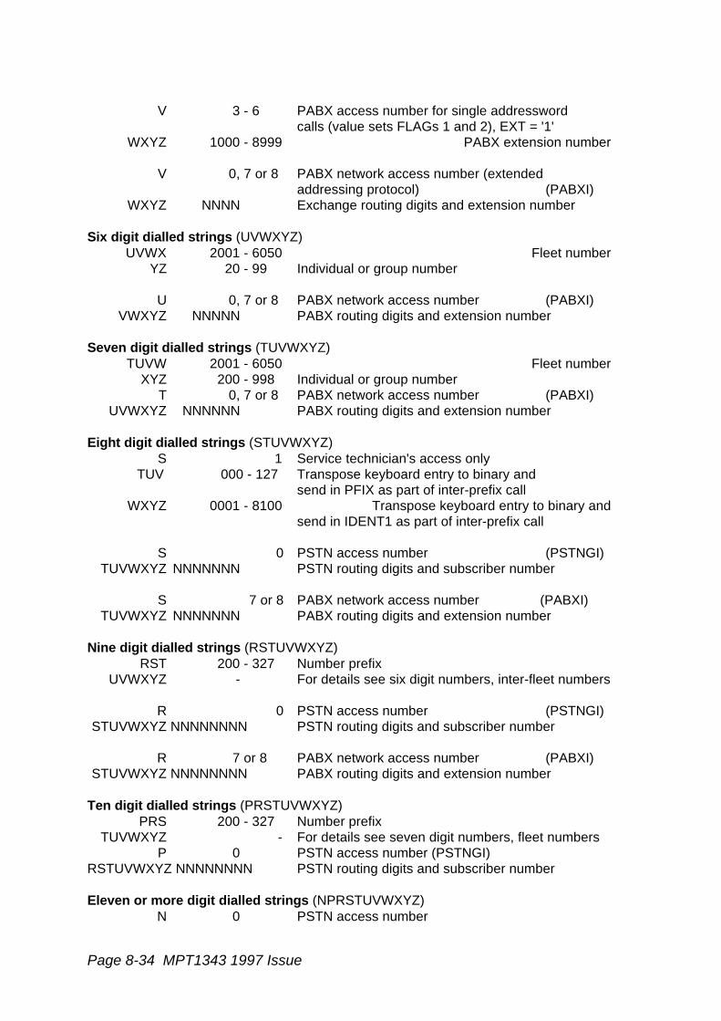
Page 8-34 MPT1343 1997 Issue
V 3 - 6 PABX access number for single addresswordcalls (value sets FLAGs 1 and 2), EXT = '1'
WXYZ 1000 - 8999 PABX extension number
V 0, 7 or 8 PABX network access number (extendedaddressing protocol) (PABXI)
WXYZ NNNN Exchange routing digits and extension number
Six digit dialled strings (UVWXYZ)UVWX 2001 - 6050 Fleet number
YZ 20 - 99 Individual or group number
U 0, 7 or 8 PABX network access number (PABXI)VWXYZ NNNNN PABX routing digits and extension number
Seven digit dialled strings (TUVWXYZ)TUVW 2001 - 6050 Fleet number
XYZ 200 - 998 Individual or group numberT 0, 7 or 8 PABX network access number (PABXI)
UVWXYZ NNNNNN PABX routing digits and extension number
Eight digit dialled strings (STUVWXYZ)S 1 Service technician's access only
TUV 000 - 127 Transpose keyboard entry to binary andsend in PFIX as part of inter-prefix call
WXYZ 0001 - 8100 Transpose keyboard entry to binary andsend in IDENT1 as part of inter-prefix call
S 0 PSTN access number (PSTNGI)TUVWXYZ NNNNNNN PSTN routing digits and subscriber number
S 7 or 8 PABX network access number (PABXI)TUVWXYZ NNNNNNN PABX routing digits and extension number
Nine digit dialled strings (RSTUVWXYZ)RST 200 - 327 Number prefix
UVWXYZ - For details see six digit numbers, inter-fleet numbers
R 0 PSTN access number (PSTNGI)STUVWXYZ NNNNNNNN PSTN routing digits and subscriber number
R 7 or 8 PABX network access number (PABXI)STUVWXYZ NNNNNNNN PABX routing digits and extension number
Ten digit dialled strings (PRSTUVWXYZ)PRS 200 - 327 Number prefix
TUVWXYZ - For details see seven digit numbers, fleet numbersP 0 PSTN access number (PSTNGI)
RSTUVWXYZ NNNNNNNN PSTN routing digits and subscriber number
Eleven or more digit dialled strings (NPRSTUVWXYZ)N 0 PSTN access number

MPT1343 1997 Issue Page 8-35
PRSTUVWXYZ NNNNNNNNNN Routing digits and subscriber number
8.2.10 Summary of Control Codes
**nn Abbreviated dialling codesnn = 1 to 15. PSTN abbreviated numbers prescribed methodnn = 16 to 49. Network operator specified abbreviated dialling
*# Call set-up abandoned, call complete
*0 Despatcher queue
*0nn Status 'nn' to despatcher
*1 Conference call
*11 Broadcast call
*1981# Priority voice system-wide call
*1982# Emergency voice system-wide call
*1983# Priority np data system-wide call
*1984# Emergency np data system-wide call
*1985# Short data system-wide call
*1987# Standard voice system-wide call
*2 Short Data on the Control Channel.
*3 *31 is prescribed. other codes are either reserved for future definition or areavailable for customisation.
*31 Non-prescribed data call
If "n" is dialled in the following codes, the function is restricted to speech calls if n = 1, ordata calls if n = 2.
*41n Divert own calls, ie calls directed to originator of diversion
*44n Divert third party calls, ie calls directed to a nominated party
*48 Queue incoming calls (speech calls only)
*49n Don't disturb
*8 Priority call
*9 Emergency call, RQE
*9xxx# Special emergency facility by arrangement with network operator
Page 8-36 MPT1343 1997 Issue
# End dialled string, accept call if radio unit is alerting
#0 Leave despatcher queue
#41n Cancel own diversions, ie allow calls to a unit for which previously a calldiversion was in force
#44n Cancel third party diversions, ie allow calls to a nominated third party forwhich previously a call diversion was in force
#45n Cancel incoming diversions
#48 Cancel queueing of incoming calls (speech calls only)
#49n Cancel Don't Disturb.
8.2.11 Glossary of Terms Specific to Section 8.2
Base Indent: The lowest value of ident allocated to a "fleet" of units
Block: An allocation of contiguous idents to a user "fleet"
Dialled String: The numbers dialled by a caller on the keypad of his radio unit to callany other party. Pre-origination dialling is employed and the end ofthe dialled string is indicated by the user dialling #
Fleet: All or a sub-set of a user's vehicles which are equipped with radiounits, and which require direct communication between users bymeans of two or three digit dialling
Fleet Number: The dialled digits which identify the identity "block" for the fleetcontaining the called unit (digits 4 to 7 of the "Network Number").Directly related to the "Fleet Base Ident"
Fleet Individual A "Fleet Number" via which calls to individual units may be madeNumber:
Fleet Group A "Fleet Number" via which calls to groups of units may be madeNumber:
Group Base Ident: The lowest value of ident allocated to a "fleet" of units for groupaddresses
Group Ident: An ident used to call a group of users
Group Number: The last group of digits in the "Network Group Number" whichidentifies the group of unit within the "fleet". Related to the "GroupIdent" via the "Group Base Ident".
Individual Ident: An ident used to call an individual user
MPT1343 1997 Issue Page 8-37
Network Number: The number by which a unit or group may be identified in a directory,all or part of which is dialled by a caller wishing to communicate withthe identified party or parties. It consists of the "Number Prefix", the"Fleet Number" and the "Unit Number"
Network Individual The number which identifies an individual unit in a "fleet"Number:
Network Group The number which identifies a group of units in a "fleet"Number:
Number Prefix: The three leading digits of the "Network Number". Directly related tothe prefix Unit Number: The last group of digits in the "NetworkIndividual Number" which identifies the unit within the "fleet". Relatedto the "Individual Ident" via the "Fleet Base Ident"
8.3 Ready for Communication Control
8.3.1 Readiness for Communication
In the signalling standard MPT 1327 the terms "off-hook" and "on-hook" are used todesignate the state of user readiness for communication. These terms have been used toreflect a parallel with the fixed telephone network where removal of the telephone handsetfrom the switch cradle indicates a readiness for communication (off-hook). When thehandset is resting in the switch cradle the user is assumed to be not ready forcommunication.
An indication of the state of readiness of a party to a call is necessary to enable thefollowing functions, applicable to commercial networks in Band III:
(a) To enable the user to instruct the radio unit to attempt to transmit a call request for acalled party address indicated by pre-origination dialling or other appropriate method(calling party off-hook).
(b) In systems which employ full off-air call set up, to enable the user to indicate to theradio unit readiness to accept an incoming call (called party off-hook). This functionis not applicable to group calls.
(c) To enable the user to instruct the radio unit to attempt to cancel a previously maderequest during the call set up phase or to request clear-down of a call in progress(calling party on-hook).
(d) To enable the user to instruct the radio unit to attempt to cancel a called party off-hook instruction during the call set up phase or to request clear-down of a call inprogress (called party on-hook).
(e) To enable the user to cancel any confidence indication generated by the radio unitfor a failed call attempt (calling or called party on-hook).
For convenience these functions are regarded as being fulfilled by a single control thatshall be able to be activated on all radio units, although it is permissible to use more thanone control for these purposes. This control, or group of controls, is designated the "Readyfor Communication Control" (RFCC).

Page 8-38 MPT1343 1997 Issue
The RFCC must be capable of providing a real indication of the state of user readiness tothe radio unit in order to support these functions. Accordingly, deliberate arrangementswhich allow the RFCC to be set by the user in an off-hook mode, and which do not reflectthe true state of user readiness, shall not be permitted.
8.3.2 The Form of the Ready for Communications Control
It is not the intention of this specification to restrict unduly the scope for individual design ofradio units. Consequently no requirements for the physical form that the RFCC shall takeare prescribed. However, the following general comments are offered to assist thedesigner of radio units.
Failure to request traffic channel clear-down at the end of communication is a potentiallyserious cause of wasted air-time. RFCC devices which do not solely rely on user disciplinein this matter are to be preferred to those, such as an ordinary switch-hook, which do.
RFCC devices which are designed to allow a means of acceptance of incoming full off-aircall set up calls even when the user did not take the correct action to clear down theprevious calls are to be preferred (eg, a unit left off-hook from a previous call shall becapable of signalling an on-hook to off-hook transition for a new incoming call).
A switch-hook type design is generally not applicable to hand portables and may not be themost suitable design in many other applications.
The design of the RFCC control shall take due account of the effects of normal operationupon road safety.
8.3.3 Control Requirements
The RFCC control, or group of controls, shall permit the user to signal the following to theradio unit, which shall then initiate the appropriate action prescribed elsewhere in thespecification:
- an instruction for a call request to a called party address indicated by pre-origination dialling, or other appropriate method; "call request initiate",
- a called party answer instruction following receipt of AHY(CHECK='1');"called party answer" (see MPT 1327 section 13.1.2.1),
- a call clear-down instruction for an individual call to which the user is a party;"call end request" (see MPT 1327 section 9.2.3.5),
- a calling party call cancellation instruction at any time prior to the receipt of aGTC message for the requested call; "call set-up abort"(see MPT 1327 section 9.2.1.7),
- an instruction to a radio unit, which is indicating call failure or termination bya continuing confidence indication, to cancel that indication; "cancelindication" (see 8.1).
The RFCC controls, or group of controls, may in addition permit the user to signal thefollowing to the radio unit:

MPT1343 1997 Issue Page 8-39
- an instruction to reject an incoming call; "incoming call reject"(see MPT 1327 section 13.1.2.1),
- an instruction to cancel a previously signalled called party off-hook state;"cancel called party answer" (see MPT 1327 section 13.1.2.6).

MPT1343 1997 Issue Page 9-1
9. CONTROL CHANNEL ACQUISITION ANDRETENTION
9.1 Introduction
When not assigned to a traffic channel (including immediately after switch-on), the radiounit shall attempt to find a control channel appropriate to the selected network. Thisrequirement, the discipline for radio units whilst on a control channel and the circumstanceswhich result in a search for a new control channel are the subjects of !!6.2.1!! of MPT 1327.However the protocol standard therein designates areas where system-dependentrequirements may be specified, in particular:
- the method by which the radio unit searches for an appropriate controlchannel,
- the criteria which a control channel must satisfy to be considered appropriateby the radio unit,
- additional rules, other than those specified in !!6.2.1.2!!, for returning to thecontrol channel acquisition procedures.
Accordingly, this section of the air-interface specification covers these system-dependentrequirements.
The methods specified in this section recognise that designers of commercial trunkednetworks operating in Band III sub-bands 1 and 2 may choose from a variety of controlchannel strategies, including:
- dedicated control channels,- dedicated control channels with load sharing,- time-shared control channels,- non-dedicated control channels.
These methods may result in the radio unit encountering a variety of control channelsituations, including:
- receiving a control channel which suffers short-term interruptions (time-shared control channels),
- suffering long-term interruptions to control channel reception during which noappropriate control channel can be received by the radio unit (non-dedicatedcontrol channels, or moving out of range of the network),
- being in a location where it is possible for more than one control channel tobe received from the selected network, involving the unit in a choice,
- being instructed to leave a control channel to enable that channel to be usedas a traffic channel (non-dedicated control channels),
- being instructed to leave or being barred from access to, a control channelas a result of a network load sharing arrangement.
Page 9-2 MPT1343 1997 Issue
The procedures specified in this section have been devised as far as possible to cater forthis range of situations, although the diversity of operational requirements represented bythese situations necessitates some restriction on the tolerance to achieve efficientoperation. In particular it should be noted that a non-dedicated control channel strategymay be inefficient in a multi-site situation where the radio unit is required to hunt throughmore than a small number of channels, but that this technique may be appropriate for smallnetworks using only a few channels.
The mandatory procedures have also been devised to bias radio units to retain their currentcontrol channel for as long as possible, consistent with the requirement for a satisfactoryquality of service for the user of the radio unit. In addition a radio unit searching for a newcontrol channel is biased towards systems which will not result in a need to register. Thesetwo qualities of the procedures are designed to minimise control channel loading.
Notwithstanding this bias, optional procedures have been included which will allow a radiounit to leave the current control channel when an alternative, preferred control channel isavailable. These options are intended to improve spectral efficiency, increase theavailability of radio units for a group call and give improved quality of service to the user.
Radio units may employ proprietary control channel hunting procedures which do notconform with the requirements of this section provided that:
- The proprietary scheme shall only be enabled when selected by radio unitpersonalisation. When the proprietary scheme is not enabled, the radio unitshall default to the use of the procedures in this section.
- The documentation describing the algorithms and procedures used in theproprietary scheme have been provided by the radio unit Manufacturer to theNetwork Operator. The standard of the documentation shall be at least tothe same depth as this section.
- The proprietary scheme has been authorised by the Network Operator.
9.2 Radio Unit Storage Requirements
9.2.1 Mandatory Storage Requirements
In order to follow the procedures specified in this section the radio unit shall provide thefollowing storage requirements appropriate to the selected network:
(a) In read-only memory:
i the control category of the radio unit for the selected network (see 9.5.2).Only one control category shall be stored per network;
ii. the channel numbers applicable to a "normal hunt sequence" for theselected network (see 9.3.3.4). The radio unit shall have the capability toenable up to 32 values of channel number defining the scope of the "normalhunt sequence" to be stored, and shall provide for the scope of the "normalhunt sequence" to be set to any value from 1 to 32 channel numbers,depending on the number of channel numbers held in read-only memory(this may be achieved by storing, as a separate parameter, the number ofchannels in the "normal hunt sequence" or by using a zero(null) value for the

MPT1343 1997 Issue Page 9-3
channel number as a null value in unused locations in the 32 value store).For each of the channel numbers stored the radio unit shall carry a record ofwhether or not it should expect to encounter a time-shared control channelon that channel number;
iii. the lowest and highest channel number which may be used by the selectednetwork;
iv. acquisition authorisation data for the selected network (see 9.3.4.2.3);
v. a flag which shall indicate whether the "comprehensive hunt sequence" shallbe suppressed for the selected network (see 9.3.3.5).
(b) In Type B memory (see section 6.2):
i. One value of the AREA sub-field of a received system identity code (or aNULL value) relating to the most recent registration attempt on the selectednetwork in accordance with the registration procedures specified in section10.
Note: It is permissible for data to be held in unprotected read/write memory whilstoperational and transferred to protected memory on power down or equivalent.
The radio unit shall discard any data held in protected read/write memory,unless its validity is reasonably assured.
(c) In read/ write memory:
i. the channel number of the control channel on which the radio unit iscurrently confirmed or, if the radio unit is not currently confirmed on a controlchannel but has been confirmed on a control channel since switch on, thechannel number of the control channel on which it was most recentlyconfirmed;
ii. A minimum of 8 records of denied registrations in accordance with theregistration procedures specified in section 10.
9.2.2 Optional Storage Requirements
In addition the radio unit may provide the following storage requirements:
(a) In read/write memory:
i. the channel number (CHAN), time-shared indicator (TSI) and system identitycode (SYS) contained in any BCAST(SYSDEF = '00000') messages(announce control channel) received from the selected network (see9.3.3.4);
ii. the channel number (CHAN) and system identity code (SYS) contained inany BCAST(SYSDEF = '00001') messages (withdraw control channel)received from the selected network (see 9.3.3.4);

Page 9-4 MPT1343 1997 Issue
iii. the channel number (CHAN), time-shared indicator (TSI) and adjacent siteserial number (ADJSITE), optionally also with system identity code (SYS),contained in any BCAST(SYSDEF = '00100') messages (broadcast adjacentsite control channel number) and BCAST (SYSDEF = '00101') messages(vote now advice) received from the selected network. If the announcedchannels have been examined by the radio unit, the signal strength of thenew channel may also be recorded (see 9.3.3.3 and 9.3.3.6);
Note: since data relevant to the selected network stored under (a)i to iii above maybe varied by subsequent BCAST messages it is recommended that this data isdiscarded at sometime between the radio unit being switched off and being madeready for service after being switched on subsequently. For these purposes a userinitiated change of selected network should be regarded as being equivalent toswitching-off the radio unit.
iv. the channel number of the control channel on which the radio unit was lastconfirmed for each registration area for which a successful registration isrecorded in the radio unit's read/write memory. If the radio unit is currentlyconfirmed on a control channel then it is that channel which is regarded asthe one on which it was last confirmed;
v. the channel number , system identity code (SYS) and signal strengthparameter of prospective control channels gleaned from the optional"background search sequence" (see 9.3.3.7);
vi. (NA-1) values of the AREA sub-field of received system identity codes (orNULL values) relating to registration attempts in accordance with theregistration procedures specified in section 10.3.
(b) In read-only memory:
i. the channel number of an unspecified number of channels which are notused by the selected network and may therefore be omitted from the"comprehensive hunt sequence" (see 9.3.3.5);
ii. NDD preference data for the selected network (see 9.3.4.2.3);
iii. a parameter TH to set the maximum time a radio unit, which implements theoptional "background search sequence", is permitted to leave the currentlyconfirmed control channel when sampling alternative control channels onwhich it may prefer to operate (see 9.3.3.7.3);
iv. a parameter TL to set the minimum time interval between successivedepartures from the currently confirmed contrl channel by a radio unit, whichimplements the optional "background search sequence", when samplingalternative control channels on which it may prefer to operate (see 9.3.3.7.1);
v. four parameters LM1, LM2, LM3 and LM4 to define the margin between thelevel of a sampled control channel, and the level of either the confirmedcontrol channel or L.0., which must be exceeded before a radio unit, whichimplements the optional "background search sequence", may identify it as aprospective control channel (see 9.3.3.7.6);
MPT1343 1997 Issue Page 9-5
vi. a parameter NS to define the number of consecutive sampling activities,carried out by a radio unit which implements the "background searchsequence", over which the criteria relating to signal strength measurementshould be satisfied for a particular channel before that channel may beidentified as a prospective control channel (see 9.3.3.7.6).
9.3 Control Channel Acquisition Procedures
9.3.1 Entry into Control Channel Acquisition Procedures
The control channel acquisition procedures enable a radio unit which is not assigned to atraffic channel to attempt to select a control channel. Control channel acquisition is aprocedure which consists of hunting for candidate control channels and attempting toconfirm that any candidate channels are appropriate to acquire.
The radio unit shall enter into the control channel acquisition procedures specified in thissection under the following circumstances:
- immediately after switch-on or a user-initiated change of selected network;
- when it has relinquished the current control channel under the mandatoryprocedures specified in section 9.4;
- when it has received a CLEAR message on a traffic channel (see !!9.2.3.8!!);
- when it has sent disconnect messages (MAINT (OPER = '011')) or timed-outon a traffic channel (see !!9.2.3.5!! and !!9.2.3.6!!);
- when it has received a call maintenance message MAINT (OPER = '110') ona traffic channel which requires it to vacate that channel (see !!9.2.3.7!!).
Also a radio unit which implements the optional "background search sequence" shall enterinto the control channel acquisition procedures described in this section:
- when it has identified one or more prospective control channels during a"background search sequence" which meet the parameters LM1, LM2, LM3,and LM4 as applicable.
In addition the radio unit may enter the control channel acquisition procedures under thefollowing circumstances:
- when the radio unit has timed-out on a random access attempt due to NR orNE being reached or TC being exceeded (see !!7.3.8!!);
- when the radio unit has received "system overload" (ACKX(QUAL='1')) as aresult of sending a random access request message, except RQR;
- at any time whilst the radio unit is in fall-back mode to enable the radio unitto search for an alternative control channel. The procedures to be adoptedby a radio unit exercising this option, including the points of entry and exitfrom the hunting procedures, are not specified and are, accordingly, notincluded in the procedural descriptions of the hunting sequences in 9.3.3.

Page 9-6 MPT1343 1997 Issue
At all times during the control channel acquisition procedures the radio unit shall mute itsreceived audio and refrain from transmission.
9.3.2 Receiver Sensitivity During Control Channel Acquisition
The radio unit shall not attempt to become active on any channel for which the receivedsignal level is less than the specified acquisition threshold.
The acquisition threshold L.2. shall be set to a signal level within the range -88 dBm to -106dBm at the input of the receiver. The level within this range shall be determined by themanufacturer and shall be set at the lowest value possible consistent with achievablemanufacturing tolerances and stability of adjustment under service conditions. When theradio unit is set to an acquisition threshold of L.2., or above, it shall not confirm the channeluntil the threshold L.2. is exceeded continuously for a minimum of 100ms. The time periodshall be concurrent with receiving a decodable control channel system codeword with thevalue of SYS field selected for verification (see 9.3.4.2.1).
L.O. shall be set at a level determined by the radio unit manufacturer which enables thehunt to be successfully completed as quickly as possible, for example by rejecting channelson which the received signal is inadequate for data to be detected.
Portable radio units may operate with a single acquisition threshold L.1. which shall be setto a signal level of -98 dBm ± 6 dBm at the input of the receiver. The radio unit shall notconfirm the channel until the threshold L.1. is exceeded continuously for a minimum of 100ms. The time period shall be concurrent with receiving a decodable control systemcodeword with the value of SYS field selected for verification (see 9.3.4.2.1).
9.3.3 Control Channel Hunting Procedures
9.3.3.1 Introduction
In order to find and acquire a control channel emanated by the selected network it isnecessary for the radio unit to hunt through candidate forward control channel frequenciesuntil an appropriate control channel is located and confirmed. This control channel huntingmay involve a variety of hunting sequences depending on the circumstances of the hunt.
The Control Channel Hunting Procedure stages described are:
(a) "Resuming a Control Channel Sequence" or "Single Channel Hunt Sequence".These are both mandatory hunts limited to a single channel number.
The "resuming a control channel sequence" allows a radio unit, after a period ofactivity on a traffic channel, to resume the control channel on which it was lastconfirmed prior to the traffic channel activity.
The "single channel hunt sequence" is employed when a radio unit is directed bythe TSC to a particular control channel (indicated by a CONT field value in a MOVEor CLEAR message) or seeks to regain a control channel after a period of inactivityon the selected network (due to being switched off or a user-initiated change ofselected network when details of the last confirmed control channel number havebeen retained by the radio unit in accordance with 9.2.1).
MPT1343 1997 Issue Page 9-7
b) "Preferential Hunt Sequence". A hunting sequence, with one mandatory stage, twooptional stages and optional procedures, which cover all channel numbers likely tobe employed as control channels by the selected network. This sequence onlyallows the radio unit to acquire a control channel for which a preference exists.
The mandatory stage serves to ensure that a radio unit will not acquire a controlchannel which will result in a need to register.
The optional stages, which have precedence over the mandatory stage, serve toensure that the radio unit will, wherever possible acquire, either:
- a control channel where the system identity code corresponds to one of aset of preferred NDD sub-sets held in its network personalisation;
or
- a control channel which satisfies the signal strength parameters LM1, LM2,LM3, or LM4 as applicable.
The optional procedures are mainly designed to increase the efficiency of thehunting sequence by allowing the radio unit initially to sample channels on which ithas recorded a successful and current registration, followed by control channelsradiated by base station sites within the vicinity (as gleaned from broadcastmessages received from the selected network). In addition, the optional proceduresallow the scope of the hunting sequence to be increased or decreased on the basisof broadcast messages received from the selected network or as a result of a radiounit implementing a "background search sequence" (see 9.3.3.7).
(c) "Normal Hunt Sequence". A mandatory hunting sequence, with optionalprocedures, which covers all channel numbers likely to be employed as controlchannels by the selected network and allows the radio unit to acquire a controlchannel, even if a need to register will result. The optional procedures allow thescope of the hunting sequence to be increased or decreased on the basis ofbroadcast messages received from the selected network.
(d) "Comprehensive Hunt Sequence". A mandatory hunting sequence, which may besuppressed for the selected network by radio unit personalisation. It covers allpossible channel numbers in use by the network, including those normally only usedfor traffic channels. This hunting sequence provides a contingency to allow controlchannels to be acquired even when channel numbers not normally employed forthis purpose are in use (in emergency reconfiguration situations, for example). Anoptional procedure allows the "comprehensive hunt sequence" to be temporarilysuspended in favour of the "normal hunt sequence".
When "resuming a control channel" or carrying out a "single channel hunt sequence" thehunting sequence shall be considered complete when the radio unit has tuned directly tothe radio channel and has carried out the appropriate confirmation procedures specified in9.3.4.
Other hunting sequences involve hunting through channel numbers appropriate to thehunting sequence. Hunting is carried out in one or more stages. For each hunt stage theradio unit shall set its receiver acquisition threshold to a particular level and examine anysignals received on the sampled channels which exceed that threshold. The radio unitshall then apply the control channel confirmation tests specified in 9.3.4 (the "control
Page 9-8 MPT1343 1997 Issue
channel confirmation procedure"). The hunting sequence may be considered completewhen either:
- a channel is found which satisfies the control channel confirmation testsspecified in 9.3.4. The hunting sequence is successfully complete;
- all channel numbers within the scope of the hunting sequence have beentested, at all appropriate acquisition threshold levels, without a channel beingfound which satisfies the control channel confirmation tests specified in9.3.4. The hunting sequence is unsuccessfully complete.
The radio unit shall carry out the hunting sequences in the order described in this section.If a hunting sequence is unsuccessfully complete, then the radio shall start the next huntingsequence. The final hunting sequence is the "comprehensive hunt sequence". Thishunting sequence cannot be unsuccessfully completed. The radio shall stay in this huntingsequence until a control channel is confirmed. However, the foregoing provisions of thisparagraph may be relaxed in the following circumstances:
- the "comprehensive hunt sequence" may be suppressed by radio unitpersonalisation for a network (see 9.3.3.5);
- a radio unit in a "comprehensive hunt sequence" may elect to performcomplete hunting sequences of any other type, returning to the"comprehensive hunt sequence" in the event of failure to confirm anappropriate control channel (see 9.3.3.5);
- a radio unit in the fall-back mode, searching for an alternative controlchannel immediately after receiving ALHF on its last confirmed controlchannel, and which fails to find and confirm a normal operation mode controlchannel whilst hunting (all prescribed hunt sequences shall be completed),shall return to its fall-back channel and attempt to confirm the fall-backchannel;
- a radio unit which is in the fall-back mode and is on a fall-back channel andelects to undertake control channel hunting may do so in a non-prescribedmanner (see 13.5).
Where a hunting stage involves more than one channel the order in which channels aresampled is generally not specified. However, in order to guard against bias towards certainchannels, radio units shall, in the absence of any requirements of this specification whichprescribe otherwise, ensure a degree of randomness in the order in which channels aresampled by one of the following:
- hunting channel numbers sequentially (eg, from lowest to highest number)but beginning the hunting stage at a random position in the sequence ofchannel numbers;
- hunting channel numbers in a random fashion;
- any other suitable randoming method.
The mandatory procedures as defined in this specification are intended to provide acomprehensive range of methods which shall be used as a basis for the design of radiounits.

MPT1343 1997 Issue Page 9-9
The mandatory procedures specified are a minimum requirement for radio units. The useof additional procedures is not prohibited provided that they are compatible with themandatory procedures. Note that, for example, a radio unit finding a channel whichsatisfies the control channel confirmation tests specified in 9.3.4 may continue the hunt inthe hope that an alternative control channel may be found with a higher received signallevel. Also, radio units need not limit the hunting procedures to the receiver sensitivitythreshold levels specified and may conduct additional hunts at other levels.
Whilst employing the hunting procedures specified in this section, radio units are permittedto sample any received signal obtained by tuning to any frequency required by theapplication of the procedures. It is conceivable that this may involve sampling of private-user channels or channels in use by commercial networks in Band III other than theselected network. Accordingly, it an express condition of this permission to sample anychannel that the radio unit shall not permit any intelligence received during huntingprocedures to be made available to the user, nor shall it transmit at any time during huntingprocedures.
9.3.3.2 Direction to a Control Channel
In certain circumstances the radio unit may receive direction from a TSC regarding thecontrol channel number on which the radio unit should seek to confirm, or the direction maybe implicit in the protocol. Two procedures are specified. The procedure which the radiounit shall employ is dependent upon the circumstances of the direction to a control channelnumber.
9.3.3.2.1 Resuming a Control Channel Sequence
When "resuming a control channel" the radio unit shall retune to the channel number of thecontrol channel on which it was last confirmed, irrespective of registration area, as recordedin its read/write memory (see 9.2). The radio unit shall be capable of receiving on theforward control channel which it is resuming within 34ms of the following instants:
- the end of any CLEAR message which, in accordance with the provisions ofsection 11.9.2.3.8, requires the radio unit to cease activity on the channel towhich it is currently tuned, provided that the value of the CONT field in theCLEAR message is 0;
- the end of the last disconnect message (MAINT (OPER='011')) sent by theradio unit on a traffic channel, or the expiry of time-out TN;
- the end of the last pressel off message (MAINT (OPER='001')) sent by theradio unit on a traffic channel following the expiry of time out TT or themaximum call duration timer, where no disconnect messages (MAINT(OPER='011')) are to be sent by the radio unit (see !!9.2.3.5!!, !!9.2.3.6!! and11.9.2.3.6);
- the end of any call maintenance message (MAINT (OPER='110')) receivedon a traffic channel which satisfies the criteria given in !!9.2.3.7!!;
- the operation of the RFCC control "call end request" by the user (8.3.3)during a group call when the radio unit is not the call originating unit (see!!9.2.3.5!!).
Page 9-10 MPT1343 1997 Issue
Before confirming the control channel the radio unit shall verify any system identity codereceived on the channel in accordance with the procedures of 9.3.4.2. In the event of thesystem identity code not meeting the verification procedures the hunting sequence shall beconsidered unsuccessfully completed. Upon unsuccessful completion of the "resuming acontrol channel sequence" the radio unit shall enter the "preferential hunt sequence".
9.3.3.2.2 Single Channel Hunt Sequence
A "single channel hunt" shall apply when the radio unit is directed by the TSC to a controlchannel other than the one on which it was last confirmed, irrespective of registration area,or when it is switched on whilst still retaining valid information from previous activity on theselected network or the user initiates a change of selected network and the radio unit stillretains valid information of previous activity on the new selected network, provided in eithercase that the radio unit is not equipped to implement the "preferential NDD sub-set huntstage" or that the "preferential NDD sub-set hunt stage" has been suppressed bypersonalisation (i.e the radio unit holds only zero-length values of PREFERRED NDD subfield data). The receiver shall be tuned to receive the nominated channel within 35ms ofthe following instants:
- the end of any CLEAR message which,in accordance with the provisions ofsection 11.9.2.3.8 requires the radio unit to cease activity on the channel towhich it is currently tuned, provided that the value of the CONT field in theCLEAR message is not 0;
- the end of any MOVE message that is applicable to the radio unit and inwhich the value of the CONT field is not 0 (see !!7.4.2!!).
The receiver shall tune immediately to the nominated channel after the following events,but need not be on channel within 35ms:
- the radio unit being switched on, provided that the unit holds a valid recordof the channel number on which the radio unit was most recently confirmedand the radio unit does not implement the optional "preferential NDD sub-sethunt stage", or holds only zero-length values of PREFERRED NDD sub-fieldin its network personalisation data (see 9.3.4.2.2);
- a change of selected network being initiated by the user, provided that theradio unit holds a valid record of the channel number on which the radio unitwas most recently confirmed on the new selected network and the radio unitdoes not implement the optional "preferential NDD sub-set hunt stage", orholds only zero-length values of PREFERRED NDD sub-field in its networkpersonalisation data (see 9.3.4.2.2).
The nominated channel shall be:
- the channel number indicated in the CONT field of the CLEAR message,when CONT is not equal to 0 (see !!5.5.4.3!!);
or
- the channel number indicated in the CONT field of the MOVE message,when CONT is not equal to 0 (see !!5.5.4.4!!);
MPT1343 1997 Issue Page 9-11
or
- the channel number held in the radio unit's read/write memory as the controlchannel on which the unit was most recently confirmed on the selectednetwork.
The radio unit shall not make any transmissions on a control channel until it has confirmedthe channel in accordance with the procedure specified in 9.3.4 (including the errorchecking procedure specified in 9.3.4.4). In the event of a failure of the control channel tomeet the channel confirmation criteria the hunting sequence shall be consideredunsuccessfully completed. Upon unsuccessful completion of the "single channel huntsequence" the radio unit shall enter the "preferential hunt sequence".
9.3.3.3 Preferential Hunt Sequence
The "preferential hunt sequence" encompasses three hunt stages which are intended toensure that the radio unit acquires a control channel which is preferred against selectedcriteria. These are the "preferential area hunt stage", which is a mandatory stage, and twooptional stages, the "preferential NDD sub-set hunt stage" and the "preferential sampledhunt stage".The mandatory "preferential area hunt stage" is intended to ensure that a hunting radio unitacquires, wherever possible, a control channel bearing an AREA sub-field in the SYS fieldwhich relates to a currently valid successful registration record held by the radio unit.Accordingly, the "preferential area hunt stage" should assist in reducing the overallregistration message load on the network.
The optional "preferential NDD sub-set hunt stage" is designed to bias the radio unit to acontrol channel where the relevant portion of the system identity code matches a value ofthe PREFERRED NDD sub-field held in the radio unit's personalisation data. This huntingstage, if employed, is designed to improve spectral efficiency and increase the availabilityof radio units for a group call.
The optional "preferential sampled hunt stage" enables radio units implementing theoptional "background search sequence" to acquire a control channel on the basis of thePREFERRED NDD sub-field or, where this is not applicable, acquire a control channel onthe basis of signal strength from a pre-sampled list of channels.
Either or both of the optional hunt stages may be implemented. In any one "preferentialhunt sequence" only one of the optional hunt stages may be carried out (depending uponthe reason for entry into the sequence) and shall be completed in advance of the"preferential area hunt stage".
Each hunting stage, except the "preferential sampled hunt stage", shall encompass thecontrol channels held in the radio unit's read-only memory as being applicable to a "normalhunt sequence". The radio unit may modify the compass of the hunting sequence frominformation held in its read/write memory as follows:
- by adding to the compass of the hunting sequence channel numbersreceived in BCAST (SYSDEF = '00000') messages from the selectednetwork,
Page 9-12 MPT1343 1997 Issue
- by removing from the compass of the hunting sequence channel numbersreceived in BCAST (SYSDEF = '00001') messages from the selectednetwork,
- by adding to the compass of the hunting sequence channel numbersreceived in BCAST (SYSDEF = '00100') messages from the selectednetwork,
- by adding to the compass of the hunting sequence channel numbersreceived in BCAST (SYSDEF = '00101') messages from the selectednetwork,
- by adding to the compass of the hunting sequence the channel numbers onwhich the radio unit was last confirmed on a control channel of the selectednetwork for each registration area for which a successful registration isrecorded in the radio unit's read/write memory (see 9.2).
Channel numbers which are covered by more than one of the above categories need onlybe added once to the compass of the hunting sequence.
In the case of the "preferential sampled hunt stage" the compass of the stage shall consistof all the prospective control channels identified during the "background search sequence"completed immediately prior to entering into the control channel hunting procedures(see 9.3.3.7).
The radio unit shall not make any transmissions on a control channel located during the"preferential hunt sequence" until it has confirmed the channel in accordance with theprocedures specified in 9.3.4 (including the AREA sub-field check specified in 9.3.4.2.6 orthe NDD sub-field check specified in 9.3.4.2.7, as appropriate).
A radio unit may implement the optional "background search sequence" (see 9.3.3.7) inwhich case it must also implement the "preferential sampled hunt stage" in the "preferentialhunt sequence".
The radio unit may independently implement the optional "preferential NDD sub-set huntstage" in the "preferential hunt sequence".
If the radio unit is carrying out the "background search sequence" and finds one or moreprospective control channels it enters the "preferential hunt sequence" via the "preferentialsampled hunt stage". If the radio unit enters the "preferential hunt sequence" for any otherreason and implements the "preferential NDD sub-set hunt stage" it shall commence the"preferential hunt sequence" with the "preferential NDD sub-set hunt stage" provided that atleast one of the preferred NDD sub-sets held in its network personalisation data has alength greater than zero.
In all other cases the radio unit commences the "preferential hunt sequence" with the"preferential area hunt stage".
9.3.3.3.1 Preferential NDD Sub-set Hunt Stage
The "preferential NDD sub-set hunt stage" is an optional hunting stage which allows a radiounit to acquire, wherever possible, a control channel bearing a sub-set of the NDD sub-fieldin the SYS field equal to the highest priority preferred sub-set held by the radio unit. The
MPT1343 1997 Issue Page 9-13
bit positions from the PREFERRED NDD sub-field which are utilized in each preferred NDDsub-set and the priority of that preferred NDD sub-set are determined by networkpersonalisation (see 9.3.4.2).
Accordingly, the "preferential NDD sub-set hunt stage" should assist, for instance, inavailability of a radio unit for group calls and optimisation of spectral efficiency.
A radio unit which implements the optional procedures described in this section shall enterthe "preferential NDD sub-set hunt stage" when any of the conditions of entry listed belowhave been satisfied, providing that the length of at least one of the values of PREFERREDNDD sub-field held in its network personalisation data is non-zero (see 9.3.4.2).
- A "resuming a control channel sequence" has been unsuccessfullycompleted.
- A "single channel hunt sequence" has been unsuccessfully completed.- The radio unit is switched on.
- The user initiates a change of selected network.
- The radio unit has left its current control channel due to failure to receive avalid system identity code (SYS) in accordance with the provisions of 9.4.1b) and c).
- An Aloha, or, additionally in the case of radio units which are equipped toemploy the MARK message, a MARK message is received in which CHAN4does not match the least significant four bits of the ten bit binaryrepresentation of the channel number of the control channel on which themessage was received and there is no match also in the next decodableAloha or MARK message (see !!6.2.1.1!!).
- The radio unit has left its current control channel due to application of thecodeword error criteria in 9.3.4.3 and 9.4.
- A MOVE message is received that is applicable to the radio unit and in whichthe value of the CONT field is 0 (see !!7.4.2!! and 11.5.5.4.4).
- A control channel system codeword is received on the current controlchannel in which the value of the LAB sub-field in the system identity codeindicates that the control category of the radio unit for the selected networkis not permitted access on that control channel and this condition is repeatedin the next decodable control channel codeword.
- A GTC message with CHAN = current channel is received which is notapplicable to the unit when the radio unit is not in the fallback mode.
- An ALHF message is received on the current control channel and the radiounit is not in the fall-back mode (see 13.3).
- An ACKX (QUAL = '0') message is received as a result of a registrationattempt by the radio unit following a demand from the TSC for the radio unitto attempt registration (see !!8.3.2.2!!).
Page 9-14 MPT1343 1997 Issue
- The radio unit has timed-out after a random access registration (RQR)attempt due to NR being reached or TC being exceeded (see !!7.3.8!!) atany time other than prior to a successful registration being achieved on anewly-confirmed control channel.
- The radio unit has timed-out due to TJ being exceeded whilst waiting forsignalling relevant to the transmission of an RQR message at any time otherthan prior to a successful registration being achieved on a newly-confirmedcontrol channel.
In addition, radio units may enter the "preferential hunt sequence" at the "preferential NDDsub-set hunt stage" when any of the following conditions of entry are satisfied provided thatthe length of at least one of the values of PREFERRED NDD sub-field held in its networkpersonalisation data is non-zero (see 9.3.4.2):
- At any time during the "comprehensive hunt sequence", at the radio unit'sdiscretion.
- When the radio unit has timed out after a random access attempt, exceptRQR, due to NR or NE being reached or TC being exceeded (see !!7.3.8!!).
- When the radio unit has received ACKX (QUAL = '1') as a result of sendinga random access message, except RQR.
One "preferential NDD sub-set hunt stage" shall be carried out, at least, with the receiveracquisition threshold set to a level of L.O. (L.1. for a single acquisition threshold portable).
Whilst engaged in a "preferential NDD sub-set hunt stage", a radio unit shall sample allchannels within the compass of the hunt for the purposes of subsequent confirmation, andrank them in order of preferred NDD sub-set with the highest priority first before seeking toconfirm any channel. The radio unit shall seek to confirm the control channel bearing thehighest priority preferred NDD sub-set first. If it fails to confirm this channel it shall seek toconfirm the channel bearing the next highest priority preferred NDD sub-set and so on indescending order of priority. Where channels bear preferred NDD sub-sets of equal prioritythen the radio unit may seek to confirm any of these channels before other channels oflower priority, provided that the above requirements are satisfied.
The radio unit shall not make any transmissions on a control channel located during the"preferential NDD sub-set hunt stage" until it has confirmed the channel in accordance withthe procedures specified in 9.3.4 (including the NDD sub-field check specified in 9.3.4.2.7).
In the event that a "preferential NDD sub-set hunt stage" at level L.0. (L.1. for a singleacquisition threshold portable) is completed without a channel being found which satisfiesthe control channel confirmation tests specified in 9.3.4 (including the NDD sub-field checkspecified in 9.3.4.2.7), or if no relevant NDD preference data exists (see 9.3.4.2.2), then the"preferential NDD sub-set hunt stage" shall be considered unsuccessfully completed andthe radio unit shall enter the "preferential area hunt stage" (see 9.3.3.3.3).
9.3.3.3.2 Preferential Sampled Hunt Stage
The "preferential sampled hunt stage" is an optional hunting stage which allows a radiounit, wherever possible, to acquire a pre-sampled control channel bearing a sub-set of theNDD sub-field in the SYS field equal to the highest priority preferred sub-set held by the

MPT1343 1997 Issue Page 9-15
radio unit. The bit positions from the PREFERRED NDD sub-field which are utilized in eachpreferred NDD sub-set and the priority of that preferred NDD sub-set are determined bynetwork personalization (see 9.3.4.2). If the lengths of the values of PREFERRED NDDsub-field held in its network personalization data are zero or if no pre-sampled controlchannels bearing a preferred NDD sub-set are available the "preferential sampled huntstage" allows a radio unit to acquire a pre-sampled control channel of increased signalstrength. Accordingly, the "preferential sampled hunt stage" should assist, for instance, inthe optimisation of spectral efficiency or the increase of call quality.
A radio unit which implements the optional procedures described in this section shall enterthe "preferential sampled hunt stage" when
- it has entered the "preferential hunt sequence" as a result of leaving itscurrent control channel having identified one or more prospective controlchannels (see 9.4.1 (q)).
Whilst engaged in a "preferential sampled hunt stage", a radio unit shall sample allchannels identified as prospective control channels during the preceding "backgroundsearch sequence" (see 9.3.3.7.6). Additionally the radio unit shall obey the requirement tosample and seek to confirm any channel numbers recorded as a result of the "backgroundsearch sequence" in the radio unit's read/write memory in the following specified order.Firstly, in order of priority, highest priority first, those control channels bearing a preferredNDD sub-set and secondly, in order of signal level, highest signal level first, those controlchannels not bearing a preferred NDD sub-set.
Prior to confirmation the radio unit shall check that the control channel bears the samesystem identity code which was recorded against the channel at identification during the"background search sequence" (see 9.3.3.7.6). The radio unit shall not seek to confirm anycontrol channel where this check is not satisfied.
The radio unit shall not make any transmissions on a control channel located during the"preferential sampled hunt stage" until it has confirmed the channel in accordance with theprocedure specified in 9.3.4. Note that in the case of a pre-sampled control channel whichdoes not bear a preferred NDD sub-set, the check specified in 9.3.4.2.7 is not carried out.
In the event that a "preferential sampled hunt stage" at level L.O. (L.1. for a singleacquisition threshold portable) is completed without a channel being found which satisfiesthe control channel confirmation tests specified in 9.3.4 then the "preferential sampled huntstage" shall be considered unsuccessfully completed and the radio unit shall enter the"preferential area hunt stage" (see 9.3.3.3.3).
9.3.3.3.3 Preferential Area Hunt Stage
The "preferential area hunt stage" is a mandatory stage which is intended to ensure that ahunting radio unit acquires, wherever possible, a control channel bearing an AREA sub-field in the SYS field which relates to a currently valid successful registration record held bythe radio unit. Accordingly, the "preferential area hunt stage" should assist in reducing theoverall registration message load on networks.
A radio unit shall enter the "preferential area hunt stage" when
- a "preferential NDD sub-set hunt stage" has been unsuccessfully completed;

Page 9-16 MPT1343 1997 Issue
- a "preferential sampled hunt stage" has been unsuccessfully completed.
In addition a radio unit which does not implement the "preferential NDD sub-set hunt stage"or holds only zero-length values of PREFERRED NDD sub-field in its networkpersonalisation data (see 9.3.4.2.2) shall enter the "preferential area hunt stage" when:
- a "resuming a control channel sequence" has been unsuccessfullycompleted;
- a "single channel hunt sequence" has been unsuccessfully completed;
- the radio unit is switched on and valid information of previous activity on theselected network is still retained in the radio unit's read/write memory, but theinformation does not include the channel number on which the radio unit waslast confirmed on the selected network (see 9.2.1);
- the user initiates a change of selected network and valid information ofprevious activity on the selected network is still retained in the radio unit'sread/write memory, but the information does not include the channel numberon which the radio unit was last confirmed on the selected network (see9.2.1);
- the radio unit has left its current control channel due to failure to receive avalid system identity code (SYS) in accordance with the provisions of9.4.1.b) and c);
- an Aloha, or, additionally in the case of radio units which are equipped toemploy the MARK message, a MARK message is received in which CHAN4does not match the least significant four bits of the ten bit binaryrepresentation of the channel number of the control channel on which themessage was received and there is not match also in the next decodableAloha or MARK message (see !!6.2.1.1!!);
- the radio unit has left its current control channel due to application of thecodeword error criteria in 9.3.4.3 and 9.4;
- a MOVE message is received that is applicable to the radio unit and in whichthe value of the CONT field is 0 (see !!7.4.2!! and 11.5.5.4.4);
- a control channel system codeword is received on the current controlchannel in which the value of the LAB sub-field in the system identity codeindicates that the control category of the radio unit for the selected networkis not permitted access on that control channel and this condition is repeatedin the next decodable control channel codeword;
- a GTC message with CHAN = current channel is received which is notapplicable to the unit when the radio unit is not in the fallback mode;
- an ALHF message is received on the current control channel and the radiounit is not in the fall-back mode (see 13.3);

MPT1343 1997 Issue Page 9-17
- an ACKX (QUAL = '0') message is received as a result of a registrationattempt by the radio unit following a demand from the TSC for the radio unitto attempt registration (see !!8.3.2.2!!);
- the radio unit has timed-out after a random access registration (RQR)attempt due to NR being reached or TC being exceeded (see !!7.3.8!!) atany time other than prior to a successful registration being achieved on anewly-confirmed control channel;
- the radio unit has timed-out due to TJ being exceeded whilst waiting forsignalling relevant to the transmission of an RQR message at any time otherthan prior to a successful registration being achieved on a newly-confirmedcontrol channel.
In addition, the radio unit may enter the "preferential area hunt stage":
- at any time during the "comprehensive hunt sequence", at the radio unit'sdiscretion;
- when the radio unit has timed out after a random access attempt, exceptRQR, due to NR or NE being reached or TC being exceeded (see !!7.3.8!!);
- when the radio unit has received ACKX (QUAL = '1') as a result of sending arandom access message, except RQR.
One "preferential area hunt stage " shall be carried out, at least, with the receiveracquisition threshold set to a level of L.0. (L.1. for a single acquisition threshold portable).
Whilst engaged in a "preferential area hunt stage" a radio unit shall obey the requirement tosample channels in a random manner as specified in 9.3.3.1, save that it may implementeither or both of the following optional procedures to allow selected channels to besampled prior to a random sampling of the remainder:
- Sample before all other channels any channel numbers recorded in itsread/write memory as a control channel of the selected network forregistration areas for which successful registrations are recorded (see 9.2).The order in which these channels are sampled is not specified.
- Sample before all other channels any channel numbers recorded in the radiounit's read/write memory which have been gleaned from BCAST (SYSDEF ='00100') or BCAST (SYSDEF = '00101') messages received from theselected network (see 9.2 and 9.3.3.6). The order in which these channelsare sampled is not specified.
When both of these optional procedures are implemented the radio unit should sample allchannels recorded in registration data before sampling any other channels gleaned fromBCAST messages.
The radio unit shall not make any transmissions on a control channel located during the"preferential area hunt stage" until it has confirmed the channel in accordance with theprocedures specified in 9.3.4 (including the AREA sub-field check specified in 9.3.4.2.6).
Page 9-18 MPT1343 1997 Issue
In the event that no valid AREA sub-field data relevant to the selected network is held inthe radio unit's read/write memory or in the event of a "preferential area hunt stage" at levelL.0. (L.1. for a single acquisition threshold portable) being completed without a channelbeing found which satisfies the control channel confirmation tests specified in 9.3.4(including the AREA sub-field check specified in 9.3.4.2.6) then the "preferential huntsequence" shall be considered unsuccessfully completed. Upon unsuccessful completionof the "preferential hunt sequence" the radio unit shall enter the "normal hunt sequence",unless the "preferential hunt sequence" was entered from the "comprehensive huntsequence" in which case the radio unit shall return to the "comprehensive hunt sequence".
9.3.3.4 Normal Hunt Sequence
The initial stage of the "normal hunt sequence" shall be carried out with the receiveracquisition threshold set to a level of L.2 (L.1. for a single acquisition threshold portable), orabove, and shall encompass the control channels held in the radio unit's read-only memoryas being applicable to a "normal hunt sequence". The radio unit may modify the compassof the hunting sequence from information held in its read/write memory as follows:
- by adding to the compass of the hunting sequence channel numbersreceived in BCAST (SYSDEF = '00000') message from the selected network;
- by removing from the compass of the hunting sequence channel numbersreceived in BCAST (SYSDEF = '00001') messages from the selectednetwork.
A radio unit shall enter the "normal hunt sequence":
- when a "preferential hunt sequence" has been unsuccessfully completed;
- immediately after switch-on, provided that the radio unit holds no validinformation of previous activity on the selected network in its memory and, inaddition, that the memory contains no value of NDD preference data with afield length which is greater than zero;
- when the user indicates a change of selected network, provided that theradio unit holds no valid information of previous activity on the selectednetwork in its memory and, in addition, that the memory contains no value ofNDD preference data with a field length which is greater than zero.
The radio unit may enter the "normal hunt sequence"
- at any time during the "comprehensive hunt sequence", at the radio unit'sdiscretion.
The radio unit shall not make any transmissions on a control channel located during the"normal hunt sequence" until it has confirmed the channel in accordance with theprocedures specified in 9.3.4.
In the event that a "normal hunt stage" at level L.2. or above is completed without achannel being found which satisfies the control channel confirmation tests specified in9.3.4, then a "normal hunt stage" may be repeated at other levels. However, before the"normal hunt sequence" may be unsuccessfully completed, a "normal hunt stage" shallhave been completed at least twice; once with the receiver acquisition threshold set to L.2.

MPT1343 1997 Issue Page 9-19
and once with the threshold set to L.O. (This does not apply for a single acquisitionthreshold portable).
Upon unsuccessful completion of the "normal hunt sequence" the radio unit shall enter the"comprehensive hunt sequence", except when the "comprehensive hunt sequence" hasbeen suppressed by radio unit personalisation for a network (see 9.3.3.5).
9.3.3.5 Comprehensive Hunt Sequence
The initial stage of the "comprehensive hunt sequence" shall be carried out with thereceiver acquisition threshold set to a level of L.2. (L.1. for a single acquisition thresholdportable) or above and shall normally encompass every channel within the range set by thelowest and highest channel numbers set by the network operator, held in the radio unit'sread-only memory. However, it is permissible for radio units to be configured to omitchannel numbers within the range of the "comprehensive hunt" by arrangement with theoperator of the selected network and by network personalisation.
A radio unit shall enter the "comprehensive hunt sequence" when
- a "normal hunt sequence" has been unsuccessfully completed.
In the event that a "comprehensive hunt stage" at level L.2, or above, is completed withouta channel being found which satisfies the control channel confirmation tests specified in9.3.4, then a "comprehensive hunt stage" may be repeated at other levels. In the eventthat no channels are found which satisfy the control channel confirmation tests duringsubsequent hunts and, providing that a comprehensive hunt stage has been completedwith the receiver acquisition threshold set to a level L.2, then the radio unit shall revert to a"comprehensive hunt stage" with the receiver acquisition threshold set to a level L.O. andshall repeat the "comprehensive hunt stage" until such a time as a channel which satisfiesthe control channel confirmation tests specified in 9.3.4 is found, except when the radio unitentered the "comprehensive hunt sequence" via the "preferential hunt sequence" as aresult of receiving ALHF, and the radio unit is in the fall-back mode, when the action takenin the "comprehensive hunt sequence" is prescribed in section 13.
For a single acquisition threshold portable completing a "comprehensive hunt stage"without a channel being found which satisfies the control channel confirmation testsspecified in 9.3.4, then the portable radio unit shall repeat the "comprehensive hunt stage"until such a time as a channel which satisfies the control channel confirmation testsspecified in 9.3.4 is found except when the radio unit entered the "comprehensive huntsequence" via the "preferential hunt sequence" as a result of receiving ALHF, and the radiounit is in the fall-back mode, when the action taken in the "comprehensive hunt sequence"is prescribed in section 13.
The radio unit shall not make any transmissions on a control channel located during the"comprehensive hunt sequence" until it has confirmed the channel in accordance with theprocedures specified in 9.3.4.
At any time during the "comprehensive hunt sequence" a radio unit may undertake a"preferential hunt sequence" or "normal hunt sequence", returning to the "comprehensivehunt sequence" in the event that the "preferential hunt sequence" or "normal huntsequence" is unsuccessfully completed. It shall be possible to suppress the

Page 9-20 MPT1343 1997 Issue
"comprehensive hunt sequence" by radio unit personalisation for a network. In this casethe radio unit shall remain in the "normal hunt sequence" with the acquisition threshold setto a level L.O. (L.1. for a single acquisition threshold portable) until such time as a channelwhich satisfies the control channel confirmation tests specified in 9.3.4 is found, unless theradio unit is in the fall-back mode, when the action taken in the "normal hunt sequence" isprescribed in section 13.
9.3.3.6 The Use of Adjacent Site Data
When confirmed on a control channel a radio unit may make use of information gleanedfrom BCAST (SYSDEF = '00100') and BCAST (SYSDEF = '00101') messages. Thesemessages may be transmitted by the selected network and contain information on thecontrol channels in use by sites in the vicinity of the transmitting site (adjacent site data) toassist radio units to acquire an appropriate control channel after leaving the current controlchannel.
The broadcast message contains both the channel number and SYS code which is beingtransmitted by the announced site and may also have a local serial number allocated(ADJSITE) to specify site location irrespective of control channel number and SYS code.The way in which ADJSITE information may be used by the radio unit is not prescribed inthis specification.
The action to be taken by the radio unit upon receipt of any BCAST (SYSDEF = '00101')message or any BCAST (SYSDEF = '00100') message is not prescribed by thisspecification but the following comments are offered for the benefit of designersimplementing schemes which utilise these facilities.
In storing the data received in the broadcast messages the unit may pre-filter the data forsuitability of use by examining the SYS code contained in the announcement. In the caseof BCAST (SYSDEF='00101') the unit may use the next slot to examine the announcedchannel and make a record of the received signal strength without incurring the risk oflosing relevant call data on the control channel on which it is confirmed.
The unit constructs a 15 position table which contains relevant data on each announcedsite. This data may include any signal strength information which might be gathered byexamination of the announced channel. The data is used to modify each of the controlchannel searches in favour of channels which are more likely to provide a satisfactoryservice than other channels which the search parameters may require. As the ADJSITEfield is peculiar to the transmitting site any table using ADJSITE may only be refreshed withdata received from the same site. A new table should be started when a new controlchannel is acquired. According to the unit design the old table may be stored, its data maybe used by reference to the SYS code, or the table may be destroyed when the unitacquires a new control channel.
9.3.3.7 Background Search Sequence
The "background search sequence" is an optional hunting sequence which is intended toallow the radio unit, while confirmed on a control channel, to gain information aboutalternative control channels. Where the "background search sequence" indicates that oneor more alternative control channels are available which may offer greater spectral
MPT1343 1997 Issue Page 9-21
efficiency (by virtue of bearing a preferred NDD sub-set) or may offer a stronger signalgiving improved quality of service to the user, the radio unit leaves the current controlchannel and enters the control channel hunting procedures (providing that certain criteriaare satisfied).
The "background search sequence", if implemented, shall be carried out as a backgroundactivity whilst the radio unit is confirmed on a control channel and is in the idle state. At allother times the "background search sequence" shall be suspended.
The sampling of control channels within the "background search sequence" takes placeduring discrete periods, each such period being referred to as either a "timed samplingactivity" or an "elected sampling activity" (see 9.3.3.7.3).
The maximum duration of a "timed sampling activity" and the minimum time betweensuccessive timed sampling activities are set by network personalisation (see 9.3.3.7.1 and9.3.3.7.3).
The signal strength criteria, by which alternative control channels are identified, must besatisfied for a number of consecutive timed sampling activities, set by networkpersonalisation, immediately preceding confirmation.
The methods employed to sample channels during either sampling activity are notprescribed by this specification save that the purpose of sampling is to determine for eachsampled channel whether it is a prospective control channel and to record, for all suchprospective control channels, the received signal level of the channel (see 9.3.3.7.6) and avalue of system identity code received in a control channel system codeword.
These techniques are most appropriate for systems using continuous control channelsbecause of difficulties in reliably determining the signal strength of time-shared controlchannels, although their use on such systems is not disallowed.
9.3.3.7.1 Performing a Sampling Activity
Sampling activities are carried out whilst confirmed on a control channel. The radio unitmay leave the confirmed control channel to perform a sampling activity to search foralternative control channels subject to the following conditions.For the "timed sampling activity":
a) The radio unit shall have been confirmed on the channel for at least a period TL,where TL is network dependent;
b) The radio unit shall not carry out a further sampling activity until timer TL hasexpired since the completion of any previous sampling activity.
For the "elected sampling activity":
c) The radio unit shall have decoded an address codeword from the forward controlchannel which is not addressed to it (ie PFIX/IDENT 1 does not match any of itsdesignated addresses for the system and is not the system-wide, all-call ident ALLI)and which indicates that one or more following forward control channel slots will beoccupied by the message of which the address codeword is the first codeword. Ifthe radio unit exercises this option the maximum duration of the sampling activity

Page 9-22 MPT1343 1997 Issue
shall not be TH (see 9.3.3.7.3) but shall be the number of slots following theaddress codeword which that codeword indicates will be occupied by the message.
For both sampling activities:
d) The radio unit shall suspend all sampling activity whilst waiting for signalling orwhilst tuned to a traffic channel and shall resume when it returns to the idle state;
e) Whilst preparing to leave the control channel as a result of 9.4.1 (b), (c), (d), or (g)the radio unit shall suspend all sampling activity;
f) Both of TL and TH (see 9.3.3.7.3) are non-zero. If either or both TL and TH arezero the radio unit shall not perform any sampling activities.
9.3.3.7.2 Actions Prior to Performing a Sampling Activity
Prior to leaving the currently confirmed control channel for the purposes of performing asampling activity the radio unit shall suspend any codeword error count in progress andretain any error counts to allow error checking to resume when the sampling activity iscompleted (see 9.3.3.7.5).
9.3.3.7.3 Actions During a Sampling Activity
Whilst carrying out any sampling activities the radio unit shall continue to indicate service tothe user where this option is implemented.
Provided that the conditions of 9.3.3.7.1 are met, the radio unit may commence a "timedsampling activity" at any time after a decodable address codeword has been received.
For the purposes of counting NS samples, where NS is network dependent (see 9.3.3.7.6),the radio unit shall not sample any channel more than once during a single "timed samplingactivity".
The radio unit shall complete the "timed sampling activity" and return to receiving theconfirmed forward control channel in sufficient time to be capable of decoding an addresscodeword in the next slot after TH continuous slots (where TH is network dependent)following the one in which the last address codeword was received prior to the "timedsampling activity" being commenced.
The number of channels sampled during each sampling activity will be dependent on theradio unit design.
9.3.3.7.4 Scope of the Background Search Sequence
The "background search sequence" shall encompass all control channels held in the radiounit's read-only memory as being applicable to a "normal hunt sequence". The radio unitmay modify the compass of the "background search sequence" from information held in itsread/write memory as follows:
- by adding to the compass of the search sequence channel numbersreceived in BCAST (SYSDEF = '00000') messages from the selectednetwork;
MPT1343 1997 Issue Page 9-23
- by removing from the compass of the search sequence channel numbersreceived in BCAST (SYSDEF = '00001') messages from the selectednetwork;
- by adding to the compass of the search sequence channel numbersreceived in BCAST (SYSDEF = '00100') messages from the selectednetwork;
- by adding to the compass of the search sequence channel numbersreceived in BCAST (SYSDEF = '00101') messages from the selectednetwork;
- by adding to the compass of the search sequence the channels numbers onwhich the radio unit was last confirmed on a control channel of the selectednetwork for each registration area for which a successful registration isrecorded in the radio unit's read/write memory (see 9.2).
9.3.3.7.5 Actions Following a Sampling Activity
After completing a sampling activity, the radio unit shall resume any codeword error countin progress prior to the sampling activity at the values of the retained results, unless therequirements of 9.4.1(q) have been met. Note that a sampling activity shall only beconsidered complete when the radio unit has entered a "preferential sampled hunt stage" inaccordance with the provisions of 9.4.1 (q) or has returned to the confirmed control channeland is capable of decoding forward control channel address codewords.
9.3.3.7.6 Criteria for Identification of Prospective Control Channels
The radio unit shall not identify any channels as prospective control channels until it hassampled all the channels detailed in 9.3.3.7.4 at least once since the current controlchannel was confirmed.
Note that during the last "timed sampling activity" immediately prior to identification ofprospective control channels, the radio unit may sample more than one channel forsubsequent identification, as shown below, providing the requirements of 9.3.3.7.3 are met.Those which satisfy criteria (a) and one of (b), (c), (d) and (e) as shown below, shall beidentified as prospective control channels.
a) The sampled channel bears a system identity code for the selected network whichthe radio unit is authorised to acquire (see 9.3.4.2.4 and 9.3.4.2.5).
b) The confirmed control channel bears a preferred NDD sub-set in the PREFERREDNDD sub-field of the system identity code, and the sampled channel bears a higherpriority preferred NDD sub-set and exceeds L.0, by a margin LM4, where LM4 isnetwork dependent.
c) The confirmed control channel bears a preferred NDD sub-set in the PREFERREDNDD sub-field and is less than or equal to L.2. and the sampled channel bears anequal priority preferred NDD sub-set and exceeds the confirmed control channel bya level margin LM2, where LM2 is network dependent.
d) The confirmed control channel does not bear a preferred NDD sub-set in thePREFERRED NDD sub-field of the system identity code, but the sampled channel
Page 9-24 MPT1343 1997 Issue
bears a preferred NDD sub-set and exceeds L.0. by a level margin LM3, whereLM3 is network dependant.
e) The confirmed control channel does not bear a preferred NDD sub-set in thePREFERRED NDD sub-field and is less than or equal to L.2., and the sampledchannel does not bear a preferred NDD sub-set but exceeds the confirmed controlchannel by a level margin LM1, where LM1 is network dependent.
See table 9-1.
All criteria relating to signal strength, ie. level margin parameters LM1-LM3, shall besatisfied for NS consecutive timed sampling activities immediately prior to the relevantchannel being identified as a prospective control channel. Note that any signal strengthmeasurements carried out during an "elected sampling activity" shall not be treated as oneof the NS samples.
The channel number, system identity code and signal strength (if appropriate) of eachprospective control channel shall be stored once identified. Following any completion ofthe confirmation procedures in 9.3.4, the radio unit shall discard all information obtainedfrom sampling activities.

MPT1343 1997 Issue Page 9-25
TABLE 9-1 CRITERIA FOR IDENTIFICATION OF PROSPECTIVE CONTROLCHANNELS
Criteria for prospectiveCONFIRMED CONTROL CHANNEL
control channelidentification
Has SYS fieldwith
preferred NDD sub-set
Has SYS field withnon-preferredNDD sub-set
SAMPLED
Sampled has lower priority.Prospective control channelis not identified.
CONTROL
CHANNELHas SYS fieldwith preferedNDD sub-set
Sampled has equal priority.(sampled signal strength -confirmed signal strength)>LM.2 and confirmedsignal strength ≥L.2
Sampled signalstrength>(L.0. + LM.3)
Sampled has higher priority.Sampled signal strength>(L.0. + LM4)
Has SYS fieldwith non-prefered NDDsub-set
Prospective control channel isnot identified
Sampled signalstrength - confirmedsignal strength) > LM.1and confirmed signalstrength ≤ L.2.
Page 9-26 MPT1343 1997 Issue
9.3.4 Control Channel Confirmation
9.3.4.1 Identifying a Candidate Control Channel
During any of the hunting procedures specified in section 9.3.3 the radio unit shall examineany signal detected for conformity with control channel structure. The radio unit shallaccept as a candidate control channel any channel on which a control channel codewordsynchronisation sequence is detected.
The method by which the radio unit identifies candidate control channels during hunting isnot detailed in this specification. In particular no maximum time allowance for thisprocedure is specified, although attention is drawn to the necessity of completing tests asquickly as possible, notably on channels which can be easily rejected as control channelcandidates (eg, no FFSK data is detected), since the overall speed of the hunt (and thusefficiency of service to the user) depends on the rapidity with which these tests can becarried out. However, if the channel number of the channels being sampled is identified asone on which a time-shared control channel may be expected in the store of channelnumbers held in the radio unit's read-only memory as applicable to a "normal huntingsequence" (see 9.2.1) or in the store of data received from BCAST messages held inread/write memory (see 9.2.2) or in the TSI field of a received MOVE or CLEAR message,then the radio unit shall sample the channel for at least a period TS before rejecting thechannel on the grounds of failure to detect a control channel codeword synchronisationsequence.
Following the receipt of a MOVE or CLEAR message where TSI='0', it is recommended thatenough time is allowed for the radio unit to sample the channel in order to decode a validcodeword that may otherwise be corrupted due to fading or other degradation in thereceived signal. Allowing extra sampling time may reduce the delay in acquiring a channelfollowing the receipt of a MOVE or CLEAR message
9.3.4.2 Checking the System Identity Code
9.3.4.2.1 Requirement to Verify System Identity Code
When the radio unit has identified a candidate control channel in accordance with section9.3.4.1, it shall examine the values of the system identity code fields (SYS) of the controlchannel system codewords received on the channel.
When NV control channel system codewords have been received consecutively with thesame value of SYS field, the radio unit shall attempt to verify that value.
The radio unit shall hold two alternative values of NV as follows:
- one value of NV shall be utilised when monitoring a channel for the purposeof selecting a value of SYS field for verification when the channel number isidentified as one on which time-shared control channels may be expected inthe store of channel numbers held on the radio unit's read-only memory asapplicable to a "normal hunting sequence" (see section 9.2.1), or in the storeof data received from BCAST messages held in read/write memory (seesection 9.2.2), or in the TSI field of a received MOVE or CLEAR message;
- the other value of NV shall be utilised when monitoring a channel for thepurpose of selecting a value of SYS field for verification when the channel
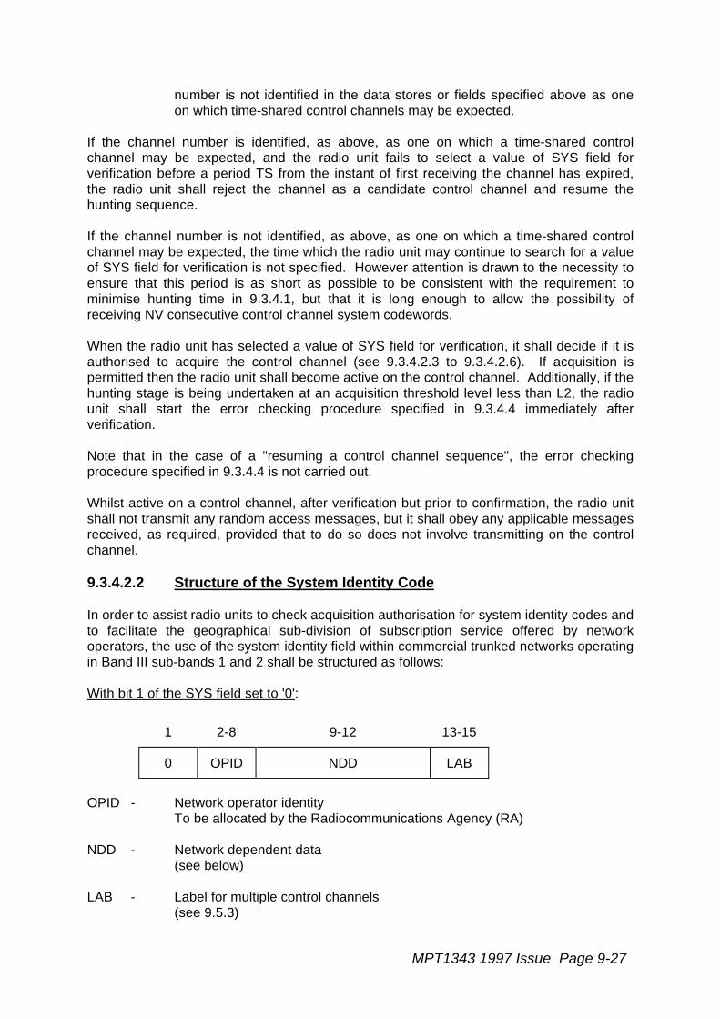
MPT1343 1997 Issue Page 9-27
number is not identified in the data stores or fields specified above as oneon which time-shared control channels may be expected.
If the channel number is identified, as above, as one on which a time-shared controlchannel may be expected, and the radio unit fails to select a value of SYS field forverification before a period TS from the instant of first receiving the channel has expired,the radio unit shall reject the channel as a candidate control channel and resume thehunting sequence.
If the channel number is not identified, as above, as one on which a time-shared controlchannel may be expected, the time which the radio unit may continue to search for a valueof SYS field for verification is not specified. However attention is drawn to the necessity toensure that this period is as short as possible to be consistent with the requirement tominimise hunting time in 9.3.4.1, but that it is long enough to allow the possibility ofreceiving NV consecutive control channel system codewords.
When the radio unit has selected a value of SYS field for verification, it shall decide if it isauthorised to acquire the control channel (see 9.3.4.2.3 to 9.3.4.2.6). If acquisition ispermitted then the radio unit shall become active on the control channel. Additionally, if thehunting stage is being undertaken at an acquisition threshold level less than L2, the radiounit shall start the error checking procedure specified in 9.3.4.4 immediately afterverification.
Note that in the case of a "resuming a control channel sequence", the error checkingprocedure specified in 9.3.4.4 is not carried out.
Whilst active on a control channel, after verification but prior to confirmation, the radio unitshall not transmit any random access messages, but it shall obey any applicable messagesreceived, as required, provided that to do so does not involve transmitting on the controlchannel.
9.3.4.2.2 Structure of the System Identity Code
In order to assist radio units to check acquisition authorisation for system identity codes andto facilitate the geographical sub-division of subscription service offered by networkoperators, the use of the system identity field within commercial trunked networks operatingin Band III sub-bands 1 and 2 shall be structured as follows:
With bit 1 of the SYS field set to '0':
1 2-8 9-12 13-15
0 OPID NDD LAB
OPID - Network operator identityTo be allocated by the Radiocommunications Agency (RA)
NDD - Network dependent data(see below)
LAB - Label for multiple control channels(see 9.5.3)

Page 9-28 MPT1343 1997 Issue

MPT1343 1997 Issue Page 9-29
With bit 1 of the SYS field set to '1':
1 2-3 4-12 13-15
0 NET NDD LAB
NET - Network operator identity
'00' National network no. 1'01' National network no. 2'10' Reserved'11' Reserved
NDD - Network dependent data(see below)
LAB - Label for multiple control channels(see 9.5.3)
Format of the network dependent data
The network operator is free to utilise the network dependent data sub-field in any waywhich conforms to the following general structure and requirements:
Bit no. 9 12 SYS bit no. 1 = '0'
ZONE
AREA
SIL
PREFERRED NDD
Bit no. 4 12 SYS bit no. 1 = '1'
ZONE - A sub-field with length set by the network operator, starting at bit 9(SYS bit no. 1 = '0') or bit 4 (SYS bit no. 1 = '1') which indicates thesubscription zone to which the system identity code belongs.
AREA - A sub-field with length set by the network operator, starting at bit 9(SYS bit no. 1 = '0') or bit 4 (SYS bit no. 1 = '1') which indicates theregistration area to which the system identity code belongs.
FREE - A sub-field with length set by the network operator ending at bit 12 ofthe SYS field which may be used for any control channelidentification purpose which the network operator specifies.
SIL - A sub-field with length set by the network operator (minimum 3),starting at bit 9 (SYS bit no. 1 = '0') or bit 4 (SYS bit no. 1 = '1') whichindicates the sub-field to be used when checking the source of
Page 9-30 MPT1343 1997 Issue
MAINT or CLEAR messages (see 11.9.2.3.3, 11.9.2.3.7 and11.9.2.3.8).
PREFERREDNDD - A sub-field with length set by the network operator starting at bit 9
(SYS bit no. 1 = '0') or bit 4 (SYS bit no. 1 = '1') which indicates thesub-field of the network dependent data which is to be preferredduring hunting.
Zero bits is a valid length of any sub-field, in which case that sub-field has no relevance toacquisition authorisation or hunting procedures.
9.3.4.2.3 Acquisition Authorisation Data and NDD Preference Data
The radio unit shall provide facilities for acquisition authorisation data to be implanted duringnetwork personalisation to enable the radio unit to carry out the verification processspecified in 9.3.4.2.1 for each possible selected network (see 9.2). This acquisitionauthorisation data shall consist of the following information for each possible selectednetwork:
- the length of the ZONE sub-field (LZ),
- the length of the AREA sub-field (LA).
In addition, the acquisition authorisation storage shall provide for any combination of thefollowing three classes of acquisition data for at least eight total entries:
- zone identity: a binary number of length equal to LZ, which authorisesacquisition of control channels conveying system identity codes bearing thatzone value;
- area identity: a binary number of length equal to LA, which authorisesacquisition of control channels conveying system identity codes bearing thatarea value;
- full identity: a binary number of length 4 bits (SYS bit no. 1 = '0') or 9 bits(SYS bit no. 1 = '1') which authorises acquisition of control channelsconveying the single identity code in the network which bears that value inbits 9 to 12 (SYS bit no. 1 = '0') or bits 4 to 12 (SYS bit no. 1 = '1').
Each zone, area or full identity entry in memory shall include an identifier to distinguish thethree classes of data (the form to be taken by this identifier is not specified).
The radio unit may provide facilities for NDD preference data to be implanted duringnetwork personalisation to enable the radio unit to carry out the verification processspecified in 9.3.4.2.7 for each possible selected network (see 9.2). This NDD preferencedata shall consist of the following information for each possible selected network:
- At least four values of PREFERRED NDD sub-field, each value referred toas a preferred NDD sub-set, which identify preferred system identity codesas ones bearing these values in the PREFERRED NDD sub-field.
MPT1343 1997 Issue Page 9-31
- For each preferred NDD sub-set a number from 0-9 indicating the length ofthe PREFERRED NDD sub-field in bits to which the value refers.
- For each preferred NDD sub-set, a number from 1 to 10, inclusive, indicatingthe order of priority (1 is highest priority, 10 lowest) in a "preferential NDDsub-set hunt stage", "preferential sampled hunt stage" or "backgroundsearch sequence". The same priority may apply to more than one preferredNDD sub-set.
9.3.4.2.4 Use of Acquisition Authorisation Data
The radio unit shall apply the following procedures when checking a system identity codeselected for verification against its acquisition authorisation data for the selected network.
If bit 1 of the selected SYS is '1', the radio unit shall check that the selected network is anational network and that a match exists between the NET field in the selected SYS andthat authorised for the selected network.
If bit 1 of the received SYS is '0', the radio unit shall check that the selected network is aregional network and that a match exists between the OPID field in the selected SYS andthat authorised for the selected network.
- If the radio unit holds no data for zone, area or full identity acquisitionauthorisation for the selected network, then it may acquire any controlchannel belonging to that network.
- If the radio holds data for zone, area or full identity acquisition authorisationfor the selected network, then the following precedence shall apply:
(a) The radio unit shall first check for a match between any zone identityacquisition authorisation data and the selected system identity code.If a match is found then acquisition is authorised.
(b) Failing acquisition authorisation at the zone identity level, the radiounit shall check for a match between any area identity acquisitionauthorisation data and the selected system identity code. If a matchis found then acquisition is authorised.
(c) Failing acquisition authorisation at the zone or area identity level, theradio unit shall check for a match between any full identity acquisitionauthorisation data and the selected system identity code. If a matchis found then acquisition is authorised.
If acquisition authorisation testing fails at all three levels, then the radio unit shall assumethat it is not authorised to acquire the control channel under test.
9.3.4.2.5 Checking the LAB Sub-field
If the radio unit has successfully verified the system identity code against its acquisitionauthorisation data for the selected network it shall examine the LAB sub-field in the light ofits control category held in read-only memory (see 9.2).
Page 9-32 MPT1343 1997 Issue
If the control category of the radio unit is not one of the categories permitted access by theLAB sub-field value (see 9.5.3), then the radio unit shall assume that it is not authorised toacquire the control channel under test.
9.3.4.2.6 Checking the AREA Sub-field
If the radio unit has successfully verified the system identity code against its acquisitionauthorisation data for the selected network and has verified that it is permitted to acquire bythe value of the LAB field, then it shall examine the AREA sub-field in the light of currently-valid records of successful and denied registrations applicable to the selected network heldin its read/write memory (see 9.2).
If the value of the AREA sub-field under examination is a value held in a currently-validrecord of denied registrations applicable to the selected network, then a radio unit shallassume that it is not authorised to acquire the control channel under test.
In addition, if the control channel confirmation is being carried out during a "preferentialarea hunt stage" and if the value of the AREA sub-field under examination is not held in acurrently-valid successful registration record for the selected network in the radio unit'sread/write memory, then the radio unit shall assume that it is not authorised to acquire thecontrol channel under test.
9.3.4.2.7 Checking the PREFERRED NDD Sub-field
If control channel confirmation is being carried out during a "preferential NDD sub-set huntstage", or, where specified, during a "preferential sampled hunt stage" (see 9.3.3.3.2), theradio unit shall examine the PREFERRED NDD sub-field of the system identity code beingverified against the NDD preference data for the selected network held in the radio unitsread-only memory. If no match can be found between any item of NDD preference dataand the selected system identity code then the radio unit shall assume that it is notauthorised to acquire the control channel under test on this basis.
9.3.4.3 Error Checking on a Control Channel
Whilst receiving a control channel a radio unit shall monitor the codeword error rate andcount the codewords received with errors (after the application of any error correctionsprocedures which may be adopted) in successive samples of NC1 or NC2 codewords(values are network dependent). Samples of length NC1 codewords shall be taken whenmonitoring the channel for the purpose of final checking prior to confirmation (9.3.4.4) andof length NC2 after confirmation. In this context a "codeword" shall be considered as thecontents of the first or second half of a slot on the forward control channel (see !!3.3.3.1!!)irrespective of the contents of that slot. Any codeword which is not decodable shall beregarded as a codeword with errors.
The radio unit shall also count as codewords with errors all errors from, and including, thefirst CCSC received with a value of SYS field different to that selected for verification, untilthe first CCSC received with a value of SYS field the same as that selected for verification
If, in any sample of NC1 codewords, the count of codewords received with errors exceedsNX1 (network dependent), or in any sample of NC2 codewords, the count of codewordsreceived with errors exceeds NX2 (network dependent), then a codeword sample errorevent shall be recorded by the radio unit. The radio unit shall hold two alternative values ofNC1/NX1 and NC2/NX2 as follows:
MPT1343 1997 Issue Page 9-33
- one set of values of NC1 and NX1 shall be utilised when monitoring achannel for the purpose of final checking prior to confirmation when thechannel number is identified as one on which time-shared control channelsmay be expected in the store of channel numbers held in the radio unit'sread-only memory as applicable to a "normal hunting sequence" (see 9.2.1)or in the store of data received from BCAST messages held in read/writememory (see 9.2.2) or in the TSI field of a received MOVE or CLEARmessage;
- the other set of values of NC1 and NX1 shall be utilised when monitoring achannel for the purpose of final checking prior to confirmation when thechannel number is not identified in the data stores or fields specified aboveas one on which time-shared control channels may be expected;
- one set of values of NC2 and NX2 shall be utilised when monitoring achannel after confirmation when the channel number is identified as one onwhich time-shared control channels may be expected in the store of channelnumbers held in the radio unit's read-only memory as applicable to a "normalhunting sequence" (see 9.2.1) or in the store of data received from BCASTmessages held in read/write memory (see 9.2.2), or in the TSI field of areceived MOVE or CLEAR message;
- the other set of values of NC2 and NX2 shall be utilised when monitoring achannel after confirmation when the channel number is not identified in thedata stores or fields specified above as one on which time-shared controlchannels may be expected.
Whilst waiting for signalling on a control channel (eg, after transmitting a random accessmessage) a radio unit shall suspend the count of codewords received with errors. Anycount in progress at the time that a radio unit enters this waiting state shall be aborted andthe result discarded.
When a radio unit leaves the control channel as a result of the circumstances specified in9.4.1 parts (b), (c), (d), (f), (g), or (m), or (h) when due to a demanded registration, it shallresume error checking. When it acquires and verifies a new channel it shall confirm thechannel (9.3.4.4) and shall then suspend error checking until it is no longer waiting forsignalling.
9.3.4.4 Final Checking Prior to Access
If a control channel, which satisfies the procedures of 9.3.4.1 and 9.3.4.2, was sampledduring a hunt at a level less than L.2., then it shall not be finally confirmed until the errorchecking procedure specified in 9.3.4.3 has produced NZ1 samples of NC1 codewords.Further if any of the NZ1 samples of NC1 codewords has produced a codeword sampleerror event then the radio unit shall reject the channel and resume hunting.
When a sampled control channel has passed all the appropriate tests in 9.3.4.1, 9.3.4.2and 9.3.4.3 then the radio unit shall regard the current hunting sequence as complete andshall consider the control channel as confirmed.
Page 9-34 MPT1343 1997 Issue
9.4 Leaving a Control Channel
9.4.1 Reasons for Leaving a Control Channel Whilst Not Waiting forSignalling
Whilst active on a control channel, either prior to acquisition being confirmed or duringactivity subsequent to control channel confirmation, the radio unit shall monitor conditionson that channel and be prepared to leave the control channel and return to the controlchannel hunting procedures. This monitoring shall continue when the radio unit is waitingfor signalling from the TSC, but the circumstances which result in the radio unit leaving thecontrol channel are reduced and are prescribed in 9.4.2 below.
When not in the state of waiting for signalling from the TSC the radio unit shall leave thecurrent control channel and enter the control channel hunting stage prescribed when:
(a) After confirmation, a codeword sample error event has been recorded in a sampleof NC2 codewords (see 9.3.4.3) and codeword sample error events are recorded ineach of NZ2 further successive samples of NC2 codewords. In this case the radiounit shall enter the "preferential hunt sequence".
(b) The value of bits 1 to 12 of the SYS recovered from decodable control channelsystem codewords received differs from the value of the bits verified duringacquisition authorisation (see 9.3.4.2.1) for a continuous period TS and the nextdecodable control channel system codeword received after the expiry of TS alsoyields a value of SYS different to the verified value (see !!6.2.1.2!!). The radio unitshall remain active on the channel after the first mismatch but shall not transmit anyrandom access message until a valid SYS value has been received, in which case itmay resume normal operation (see !!6.2.1.2!!). After leaving a control channel inthese circumstances, the radio unit shall enter the "preferential hunt sequence",unless it is prior to confirmation when it shall resume hunting procedures.
(c) No decodable control channel system codewords are received over a continuousperiod in excess of TS (see !!6.2.1.2!!). In this case the radio unit shall enter the"preferential hunt sequence", unless it is prior to confirmation when it shall resumehunting procedures.
(d) An Aloha or, in the case of radio units which are equipped to employ the MARKmessage, a MARK message is received in which the value of CHAN4 does notmatch the least significant four bits of the channel number of the control channeland there is also no match in the next decodable Aloha or MARK message. Theradio unit shall remain active on the channel after the first mismatch but shall nottransmit any random access message and shall leave the channel immediately afterthe second mismatch, unless a valid CHAN4 value has been received in the interimin which case it may resume normal operation (see !!6.2.1.2!!). After leaving acontrol channel in these circumstances the radio unit shall enter the "preferentialhunt sequence", unless it is prior to confirmation when it shall resume huntingprocedures.
MPT1343 1997 Issue Page 9-35
(e) The user initiates a change of selected network. In this case the radio unit shallassume control channel acquisition procedures on the new selected network withthe "single channel hunt sequence", the "preferential hunt sequence", or the "normalhunt sequence" depending on what valid information of previous activity on the newselected network is held in the radio unit's read/write memory.
(f) A MOVE message applicable to the radio unit is received (see !!7.4.2.!!). In thiscase the radio unit shall note the value of the TSI field and enter either the "singlechannel hunt sequence" or the "preferential hunt sequence" depending on the valueof the CONT field in the MOVE message.
(g) A control channel system codeword is received in which the value of the LAB sub-field in the system identity code indicates that the control category of the radio unitfor the selected network is not permitted access on the current control channel andthe LAB value in the next decodable control channel system codeword alsoindicates that the radio units control category is not acceptable. The radio unit shallremain active on the channel after the first failure but shall not transmit any randomaccess message and shall leave the channel immediately after the second failure,unless a value of LAB sub-field is received in the interim which does permit accessby the unit, in which case it may resume normal operation (see 9.5.3). After leavinga control channel in these circumstances the radio unit shall enter the "preferentialhunt sequence", unless it is prior to confirmation when it shall resume huntingprocedures.
(h) The radio unit receives ACKX(QUAL='0') as a result of sending a random accessregistration (RQR) message (see !!8.2.2.3!!), or as a response to an RQR sent inreply to a registration demand by the TSC (see !!8.3.2.2!!). In the case of a randomaccess registration request (not permitted prior to confirmation) or a registrationdemand received whilst the radio unit is seeking to make a random accessregistration request, the radio unit shall assume the hunt stage that it was lastengaged in prior to the registration attempt. It may either resume the hunt stage atthe channel number it would have sampled next or commence the hunt stage anew.In the case where a registration demand was received at any other time, the radiounit shall enter the "preferential hunt stage", unless it is prior to confirmation when itshall resume hunting procedures.
(j) After confirmation, the radio unit receives ACKX(QUAL='1') as a result of sending arandom access registration request (RQR) message (see !!8.2.2.3!!). In this casethe radio unit shall assume the hunt stage that it was last engaged in prior to theregistration attempt. It may either resume the hunt stage at the channel number itwould have sampled next or commence the hunt stage anew.
(k) After confirmation, the radio unit has timed out after a random access registration(RQR) attempt due to NR being reached or TC being exceeded (see !!7.3.8!!). Inthis case if the registration attempt is being carried out prior to a successful re-registration being achieved on a newly-confirmed control channel the radio unit shallassume the hunt stage that it was last engaged in prior to the registration attempt. Itmay either resume the hunt stage at the channel number it would have samplednext or commence the hunt stage anew. If the registration attempt is being carriedout at any other time the radio unit shall enter the "preferential hunt sequence".
(l) When the radio unit receives an ALHF message or equivalent (see 13.6) and theradio unit is not in the fall-back mode (see 13.3). In this case the radio unit shall
Page 9-36 MPT1343 1997 Issue
enter the "preferential hunt sequence". If the radio unit is equipped with the fall-back option it shall obey the procedures of section 13.
(m) When the radio unit receives a GTC message which it has not obeyed in which thedesignated traffic channel is the control channel on which the message wasreceived and the radio unit is not in the fallback mode (see !!9.2.2.5!!). In this casethe radio unit shall enter the "preferential hunt sequence".
In addition to these mandatory conditions a radio unit may leave the current controlchannel and enter the control acquisition procedures when:
(n) After confirmation, the radio unit receives ACKX(QUAL='1') as a result of sending arandom access request message, except RQR. If the radio unit leaves the controlchannel as a result of exercising this option it shall enter the "preferential huntsequence".
(p) After confirmation, the radio unit has timed-out after a random access attempt,except RQR, due to NR or NE being reached or TC being exceeded (see !!7.3.8!!).If the radio unit leaves the control channel as a result of exercising this option it shallenter the "preferential hunt sequence".
(q) After confirmation, the radio unit has identified one or more prospective controlchannels as a result of carrying out a "background search sequence" (see 9.3.3.7).If the radio leaves the control channel as a result of exercising this option it shallenter the "preferential hunt sequence".
In addition a radio unit may leave the current control channel, temporarily, when:
(r) It has received a BCAST (SYSDEF ='00101') message. In this case the radio unitshall switch to the channel indicated by the CHAN field in the message and shallreturn to the confirmed control channel in sufficient time to be able to decode anyaddress codeword which may be transmitted in the forward direction in the secondslot following the slot containing the BCAST (SYSDEF ='00101') message.
(s) In the course of implementing a "background search sequence" it initiates asampling activity in accordance with the requirements of section 9.3.3.7.
9.4.2 Leaving a Control Channel Whilst Waiting for Signalling
A radio unit waiting for signalling shall leave the control channel on which it is currentlyactive when any of the following events as listed in 9.4.1 above occur: (b), (c), (d), (f), (g),(h) due to a demanded registration, and (m). In such circumstances the radio unit shallretain its state of waiting for signalling during any hunting procedures and subsequentcontrol channel confirmation tests. Any timers relevant to the waiting state shall bemaintained.
In addition, a radio unit which times-out on the expiry of timer TJ whilst waiting for signallingrelevant to the transmission of an RQR message shall:
i. If the registration attempt is being carried out prior to a successful re-registrationbeing achieved on a newly-confirmed control channel, assume the hunt stage that itwas last engaged in prior to the registration attempt. It may either resume the hunt
MPT1343 1997 Issue Page 9-37
stage at the channel number it would have sampled next or commence the huntstage anew.
ii. If the registration attempt is being carried out at any other time, enter the"preferential hunt sequence".
A radio unit which enters the control channel acquisition procedures whilst in the waitingstate shall obey the hunting procedures specified in 9.3.3 and the control channelconfirmation procedures specified in 9.3.4. In addition, whilst in the waiting state, the radiounit shall only confirm a control channel in which the value of bits 1-12 of the systemidentity code (SYS) being examined under the procedure specified in 9.3.4.2 matches bits1-12 of the system identity code which was examined to authorise acquisition of the controlchannel on which the radio unit was last confirmed. A radio unit which, having entered thecontrol channel acquisition procedure whilst in the waiting state, times out on any of thetimers TA, TC, TJ or TW as appropriate to its condition, shall continue to search for acontrol channel but shall resume the control channel acquisition procedures, but without theapplication of the additional SYS code check specified above.
A radio unit waiting for signalling which leaves the control channel on which it is currentlyactive due to events (e) or (l) listed in the foregoing 9.4.1 shall cancel its waiting forsignalling state upon entering the control channel acquisition procedures. It should benoted that events (a), (h) for a random access registration request, (j), (k), (n), (p), (q), (r)and (s) are not applicable to a radio unit in the state of waiting for signalling.
9.5 Multiple Control Channels
9.5.1 Introduction
Commercial networks in Band III sub-bands 1 and 2 may operate with multiple controlchannels at a single site and may require the subdivision of the radio unit population toallow load sharing between control channels. This facility is provided by the LAB sub-fieldin the system identity code (see 9.5.3) and by control categorisation of radio units (see9.5.2).
9.5.2 Control Categorisation of Radio Units
At the time of network personalisation the radio unit shall be allocated a control category(CCAT) and this category shall be stored in the radio unit's read-only memory. Four controlcategories are available, which are designated A, B, C and D for convenience.
The control category governs acquisition and retention of a control channel, since the LABsub-field in the system identity code indicates which radio unit control categories areallowed to use a control channel (see 9.3.4.3 and 9.4).

Page 9-38 MPT1343 1997 Issue
9.5.3 The LAB Sub-field
The LAB sub-field occupies bits 13 to 15 of the system identity code (see 9.3.4.2.2). Themeanings assigned to the eight possible values of LAB shall be:
'000' Reserved (future definition in MPT 1343)'001' All categories permitted'010' Categories A and B only permitted'011' Categories C and D only permitted'100' Category A only permitted'101' Category B only permitted'110' Category C only permitted'111' Category D only permitted
MPT1343 1997 IssueMPT1343 1997 Issue Page 10-11
10 REGISTRATION
10.1 General
10.1.1 Introduction
Registration is a method of recording the area or group of areas where a radio unit is likelyto be located within a network. This information avoids searching for radio units throughoutthe whole network, consequently reducing call set-up time and control channel loading.
A secondary feature is that it provides a means of restricting the service of individual radiounits by allowing the network to deny registration requests.
The registration strategy enables networks to operate single or multiple registration. It ismandatory for radio units to support single registration, and multiple registration is astandard option. On networks which employ multiple registration, single registration radiounits may make more registration requests than multiple registration radio units. Since thesingle registration radio unit is registered in only one area however, it is likely that fewerAHOY messages from the network would be required to locate it. Registration strategy isdetermined by the network and may be broadcast to radio units to allow them to takeappropriate actions.
The registration strategy describes two types of registration. The first of these is explicitregistration, where registration is achieved by means of an RQR message (either randomaccess or demanded). The second is implicit registration, appropriate to multipleregistration type radio units, where registration is achieved by means of messagesexchanged during call set-up. Only messages that terminate control channel signalling areused for implicit registration.
It is possible that due to a failure the network may not be able to maintain registrations, butwill want radio units to use the network as if they are registered. The network maybroadcast a message to indicate that a temporary registration mode is in operation. Radiounits which receive this message will recognise the temporary registration mode, and maybe required to re-register on receipt of a further broadcast message indicating that thenetwork is in a normal registration mode.
10.2 Single Registration
10.2.1 Procedure
The single registration procedure specified in this section enables a network to record thelikely area in which a radio unit is located.
10.2.1.1 The Principle
The principle of registration requires that the radio unit shall only retain a valid registrationrecord where it has received confirmation that it is the same record as that currently heldwithin the network. If there is any doubt that the record is correct, then a NULL indicator

Page 10-212 MPT1343 1997 IssueMPT1343 1997 Issue
must be written against the record. If a radio unit fails to receive a response to a registrationrequest, this could be due to:
- the request not being received by the network, in which case the network willregard the previous successful registration by the unit as the currently-validregistration record;
- the request being accepted by the network but the acknowledgement notbeing received by the radio unit, in which case the network will regard theunsuccessful registration by the unit as the currently-valid registration record;
- the request being denied or failed by the network but the acknowledgementnot being received by the radio unit, in which case the network may eitherregard the previous successful registration by the unit as the currently-validregistration record or record a NULL registration for the calling unit.
Accordingly, in such cases the radio unit is not able to confirm whether the network holds avalid record for the unit and if it does, whether it is the previous registration or the presentregistration. It shall therefore, when making a registration attempt, write the registrationrecord into its memory at the time of making the registration attempt but, at the same time,write a NULL indicator against the record. When the successful registration is confirmed bya suitable acknowledgement from the system the radio unit shall then cancel the NULLindicator.
10.2.2 Storage and Timing requirements
10.2.2.1 Requirements
In order to follow the procedures specified in this section the radio unit shall provide thefollowing storage requirements appropriate to the selected network:
a) In Type 'B' read/write memory (see section 6.2):
The registration record applicable to the selected network. The registration record shallinclude the value of the verified AREA code and may include the channel number of thecontrol channel on which that explicit registration attempt was carried out. The registrationrecord shall also include a flag to indicate whether the registration record is normal ortemporary. Until the radio unit is switched off, or equivalent, the flag shall also be capableof indicating an undefined state prior to being set.
The radio unit shall discard any data held in protected read/write memory unless its validityis reasonably assured. Also it should be noted that the values described in 10.2.2.1(a) maybe held in unprotected RAM while operational and transferred to protected RAM on switchoff or equivalent.
The registration records used by a single registration radio unit are indicated in Table 6.1as "Prime registration" records.

MPT1343 1997 IssueMPT1343 1997 Issue Page 10-31
b) In read/write memory:
i. At least 8 different values of AREA sub-field of the received system identitycode verified when acquiring the control channel on which a registrationattempt by the radio unit has been denied. These shall be managed as aFIFO list: when the radio unit has a full list of entries, any further addition tothe list shall displace the earliest entry.
ii. The latest value of the REG parameter received on the control channel toindicate whether the control channel is in the normal or temporaryregistration mode (an undefined state shall be indicated prior to receipt ofREG within a session).
c) In read-only memory, which shall be set by network personalisation:
A value of the ZONE field which shall be designated as the 'home' ZONE of the radio unit.
Note: A single registration type radio unit shall ignore the NA field advised by any BCAST(SYSDEF='00011') messages successfully decoded during activity on the selectednetwork.
10.2.2.2 Action on Switch-off or Switch-on or equivalent
Data held under 10.2.2.1 b) shall be discarded at some time between the radio unit beingswitched off and being made ready for service after being subsequently switched on. Forthese purposes a user-initiated change of selected network shall be regarded as beingequivalent to switching off the radio unit.
If, at switch-off (or equivalent), the registration record is currently labelled as undefined (seesections 10.2.4.1.1 and 10.2.4.2.1), then at some time between the radio unit beingswitched off and being made ready for service after being subsequently switched on, theregistration record shall be labelled as normal.
10.2.3 Action on confirmation of a control channel
A radio unit shall not make any attempt at random access until control channel confirmationhas been achieved, see 9.3.4.4.
When a radio unit confirms a control channel it shall then:
i. If the verified AREA code is zero, or the radio unit is personalised with a zerolength AREA field, or the radio unit is in fall-back mode, the radio unit shallnot seek to register by random access nor shall it create or alter anyregistration record. The radio unit shall note that registration is not requiredand that it is free to initiate calls.
Otherwise:
ii. If the verified area code is in the list of denied registrations, the radio unitshall resume hunting (see section 9).
Page 10-412 MPT1343 1997 IssueMPT1343 1997 Issue
Otherwise:
iii. If the radio unit does not hold a successful registration record for the verifiedAREA code, the radio unit shall attempt to register by random access (seesection 10.2.4) according to normal rules (see !!7.3!!).
Otherwise:
iv. If the radio unit holds a successful registration record for the verified AREAcode it shall not attempt to register. If the radio unit is of a type which storesthe relevant channel number in the registration record and, if the storedchannel number is different from the current number, then the radio unit shallreplace the stored channel number in the record by the current channelnumber without otherwise affecting the registration record.
Once confirmed on a control channel, the radio unit shall not transmit any message otherthan RQR, or an acknowledgement in response to an Ahoy with IDENT1 = REGI(!!8.2.2.4!!), until it holds a successful registration record relating to the verified AREA code(unless the verified AREA code is zero, or the radio unit is personalised with a zero lengthAREA field, or the radio unit is in the fall-back mode) with the exception regarding a requestfor the radio unit security number detailed in the next paragraph. If at any time whilst activeon a control channel the radio unit ceases to hold a successful registration record relatingto the verified AREA code, it shall refrain from transmitting any message other than RQR,or an acknowledgement in response to an Ahoy with IDENT1 = REGI (!!8.2.2.4!!), until asuccessful registration record relating to the verified AREA code is held (unless the verifiedAREA code is zero, or the radio unit is personalised with a zero length AREA field, or theradio unit is in the fall-back mode). Whilst restricted in its transmissions due to not holdingan appropriate registration record the radio unit shall obey any applicable messagesreceived, as required, provided that to do so does not involve transmitting on the controlchannel (other than RQR or an ACK to an AHY with IDENT1 = REGI).
Having transmitted an RQR with the "Security Number Flag" set to '1', the radio unit shallbe prepared to respond to a request from the TSC consisting of an AHYC, Mode 2IDENT2=TSCI, DESC='000') with a SAMIS containing the radio unit security number (seeSection 7 item 8) before expecting an acknowledgement to the registration request. (Note:In earlier versions of MPT1343, the INFO field of the RQR has a 3 bit RSVD field. Bit 3 ofthis field is now assigned to the "Security Number Flag". Annex AN2 illustrates thesefields)
At any time that the radio unit holds a successful registration record relating to the verifiedAREA code, it is free to transmit any message conforming to the requirements of thisspecification.
10.2.4 Registration Procedures
10.2.4.1 Registration by Random Access

MPT1343 1997 IssueMPT1343 1997 Issue Page 10-51
When a radio unit determines that it is required to register, it shall attempt to do so byrandom access using the procedures defined in MPT 1327 section 8.2.2. Note that if theregistration is occasioned by the receipt of BCAST (SYSDEF = '00011'), then the actionsprescribed in section 10.2.7 c) or d) shall be performed prior to those defined below.
If the random access timeout TC expires and the radio unit has not sent a registrationrequest (!!8.2.2.2!!), the radio unit shall enter the control channel acquisition procedures(section 9).
Immediately upon sending the registration request by random access, the radio unit shallwrite into memory the AREA code for the system to which it is making the request togetherwith a NULL indicator and delete the AREA code retained from its previous registration.The action after transmitting a random access registration request shall be as specified insections 10.2.4.1.1 to 10.2.4.1.5.
10.2.4.1.1 Registration accepted
The registration attempt shall be considered successful on receipt of ACK(QUAL = '0').The radio unit shall:
a) convert the NULL record to a successful registration record by removing the NULLindicator and
b) if the radio unit has received a REG parameter (see 10.2.7) since commencing thesession, it shall label the registration record as either normal or temporary,corresponding to the latest received value of REG. If the radio unit has not receiveda REG parameter (see 10.2.7) since commencing the session, it shall label theregistration record as undefined (see also 10.2.2.2 and 10.2.7).
10.2.4.1.2 Registration Denied
The registration attempt shall be considered denied on receipt of ACKX(QUAL = '0'). Theradio unit shall:
a) write the AREA code in the list of denied registration records (see section 10.2.2),
and
b) enter the control channel acquisition procedures (see section 9).
10.2.4.1.3 Registration Failed
The registration attempt shall be considered to have been unsuccessful upon receipt ofACKX(QUAL='1').
The radio unit shall resume hunting, see 9.4.1(j), and after confirmimg a control channeland receiving a suitable Aloha message, shall re-commence a random access registrationattempt in accordance with section 8.2.2 of MPT1327.

Page 10-612 MPT1343 1997 IssueMPT1343 1997 Issue
Note that, until a successful registration is achieved, the radio unit shall not attempt totransmit other than RQR messages, or an acknowledgement in response to an Ahoy withIDENT1 = REGI (!!8.2.2.4!!), or a SAMIS in response to an AHYC Mode 2 demanding itssecurity number, but shall continue to obey any received messages, provided that to do sodoes not involve transmitting on the control channel (other than RQR, or an ACK to anAhoy with IDENT1 = REGI).
10.2.4.1.4 Registration Attempt Times Out
If the radio unit times out from waiting for further signalling for the registration (!!8.2.2.4!!),or cancels its wait state as defined in section 9.4.2, it shall enter the control channelacquisition procedures (section 9).
10.2.4.1.5 Registration Demand Received During a Random AccessRegistration Transaction
If, while waiting for a response to a random access registration request message, the radiounit receives an ALHR message individually addressed to it, the radio unit shall send aregistration request RQR in accordance with MPT 1327 section 8.3.2.1 a2 (the radio unitshall not send an emergency request RQE).
The action shall then be as defined in sections 10.2.4.1.1 to 10.2.4.1.4, and in sections 7.3and 8.2.2.2 of MPT 1327.
10.2.4.2 Registration on Demand
If, whilst confirmed on the control channel and not attempting to register by random access,a radio unit receives an applicable individually addressed ALHR, it shall write a NULLrecord against the existing registration record for the currently verified AREA code and shallattempt to register, complying with the procedures defined in MPT 1327 section 8.3.2.
The radio unit action after transmitting RQR upon demand, whilst not attempting to registerby random access, shall be as defined in sections 10.2.4.2.1 to 10.2.4.2.3.
10.2.4.2.1 Registration Accepted
On receipt of ACK(QUAL='0') the registration shall be considered accepted and the radiounit shall:
a) convert the NULL record to a successful registration record by removing the NULLindicator, and
b) if the radio unit has received a REG parameter (see 10.2.7) since commencing thesession, it shall label the registration record as either normal or temporary,corresponding to the latest received value of REG. If the radio unit has not receiveda REG parameter (see 10.2.7) since commencing the session, it shall label theregistration record as undefined (see also 10.2.2.2 and 10.2.7).

MPT1343 1997 IssueMPT1343 1997 Issue Page 10-71
10.2.4.2.2 Registration Denied
Registration is denied if ACKX(QUAL='0') is received. On receipt of this message the radiounit shall:
a) write the AREA code in the list of denied registration records, and
b) enter the control channel acquisition procedures (section 9).
10.2.4.2.3 No Acknowledgement Received
If no response is received within WAIT+1 slots, the radio unit shall make no consequentialchanges to its registration record. If, as a result of the action prescribed in 10.2.4.2, theradio unit has no registration record for the verified AREA code, then it shall attempt toregister by random access.
10.2.5
This paragraph is not used.
10.2.6
This paragraph is not used.
10.2.7 Action on receiving broadcast registration parameters
a) The radio unit shall not make use of the NA field.
b) If the radio unit holds an undefined registration record for the verified AREA code,the record shall be labelled as either normal or temporary corresponding to thevalue of REG received.
c) If the radio unit receives REG ='0' while active on a control channel, it shall recordthat the channel is in the normal registration mode.
If the radio unit holds a temporary registration record for the verified AREA code, itshall delete that record and attempt to register by random access.
d) If the radio unit receives REG ='1' while active on a control channel, it shall recordthat the channel is in the temporary registration mode.
If the radio unit holds a normal registration record (not temporary) for the controlchannel, and the ZONE value of the verified system identity code differs from the'home' ZONE of the radio unit, the radio unit shall label the registration record astemporary.
Note that b), c) and d) shall apply to all registration records held by the radio unit, not onlythe prime records.

Page 10-812 MPT1343 1997 IssueMPT1343 1997 Issue
10.2.8 Fall-back Mode
Any radio unit (whether or not it implements the fall-back mode option) which receives anALHF message on a control channel for which the verified AREA code corresponds to aregistration record, but for which the verified ZONE code does not match its home zone,shall label the registration record as temporary.
10.2.8.1 Entering Fall-back Mode
Upon entering fall-back mode (see 13.3) a radio unit shall continue to maintain registrationrecords. Whilst in the fall-back mode and confirmed on the fall-back channel, the radio unitshall not attempt to register by random access; the radio unit is free to initiate and receivecalls even if the unit does not have a registration record for the verified AREA code.
10.2.8.2 Leaving Fall-back Mode
Upon leaving the fall-back mode the radio unit shall attempt to register if required to bysections 10.2.3 or 10.2.7.
10.3 Multiple Registration
10.3.1 Introduction
As a radio unit travels within range of more than one registration area, it may be advisableto guard against frequent re-registration, otherwise excessive registration request signallingmay be generated. The multiple registration procedure specified in this section aims tominimise this problem. It provides a mechanism whereby the radio unit may be registeredin more than one area simultaneously and so can move freely between the areas for whichit has valid registrations without re-registering
To minimise the number of radio units simultaneously registered in more than one area(thereby minimising the amount of Ahoy signalling), there is a time-out mechanism whereby'old' registrations expire if the radio unit does not make any calls in the area for a specifiedtime. The specification defines the time-out in the radio unit; the network may operate acorresponding time-out.
Although old registrations in the radio unit expire after a time-out, the most recent, or prime,registration does not expire, in order to avoid periodic re-registration.
It is important that the registration records stored in the radio unit and in the networkcorrespond. If a radio unit believes it is registered in a particular area, but the network doesnot, then the radio unit will not receive any calls while in that area. Much of thespecification serves to maintain this correspondence as closely as possible, despitecorruption of signalling. Any discrepancy must be 'fail-safe', ie the network may hold arecord of registration that the radio unit does not hold, but the radio unit must not believethat it is registered in an area that the network has not recorded.
10.3.1.1 The Principle
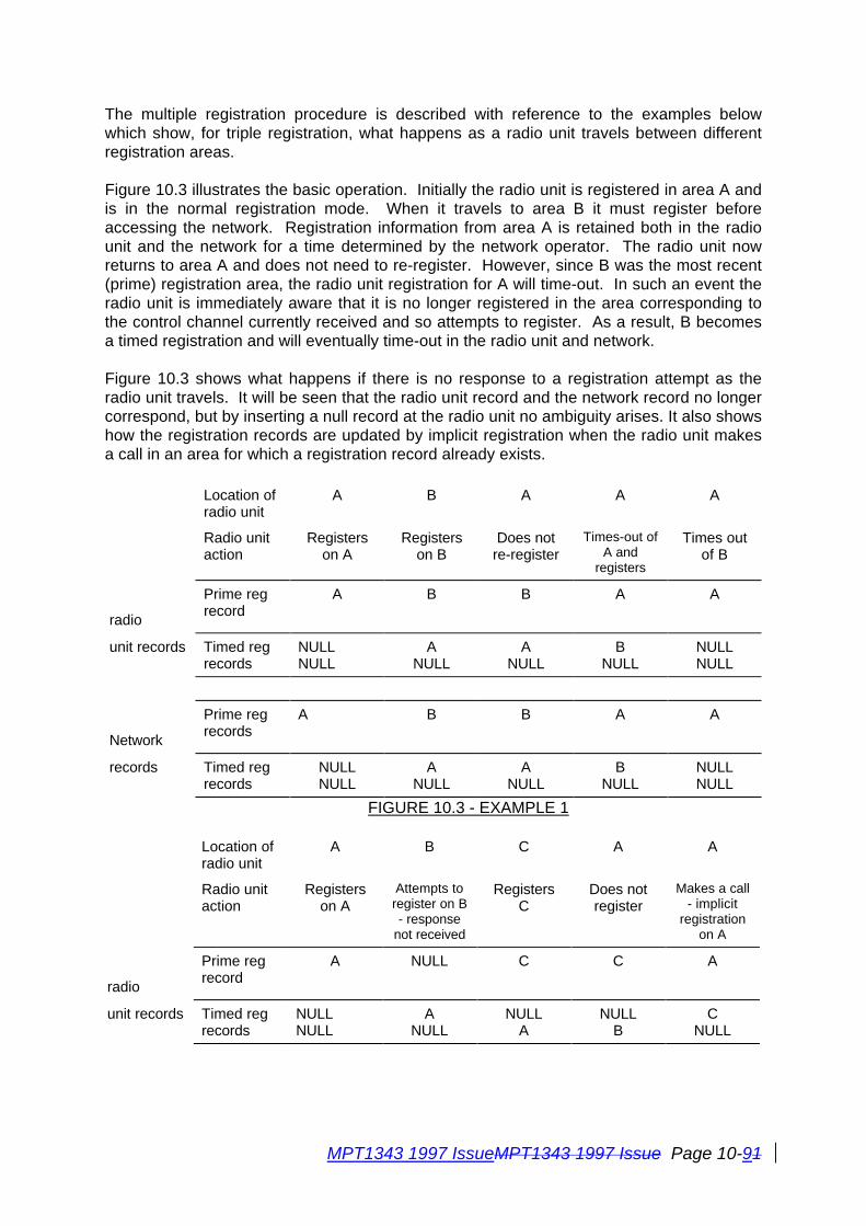
MPT1343 1997 IssueMPT1343 1997 Issue Page 10-91
The multiple registration procedure is described with reference to the examples belowwhich show, for triple registration, what happens as a radio unit travels between differentregistration areas.
Figure 10.3 illustrates the basic operation. Initially the radio unit is registered in area A andis in the normal registration mode. When it travels to area B it must register beforeaccessing the network. Registration information from area A is retained both in the radiounit and the network for a time determined by the network operator. The radio unit nowreturns to area A and does not need to re-register. However, since B was the most recent(prime) registration area, the radio unit registration for A will time-out. In such an event theradio unit is immediately aware that it is no longer registered in the area corresponding tothe control channel currently received and so attempts to register. As a result, B becomesa timed registration and will eventually time-out in the radio unit and network.
Figure 10.3 shows what happens if there is no response to a registration attempt as theradio unit travels. It will be seen that the radio unit record and the network record no longercorrespond, but by inserting a null record at the radio unit no ambiguity arises. It also showshow the registration records are updated by implicit registration when the radio unit makesa call in an area for which a registration record already exists.
Location ofradio unit
A B A A A
Radio unitaction
Registerson A
Registerson B
Does notre-register
Times-out ofA and
registers
Times outof B
radio
Prime regrecord
A B B A A
unit records Timed regrecords
NULLNULL
ANULL
ANULL
BNULL
NULLNULL
Network
Prime regrecords
A B B A A
records Timed regrecords
NULLNULL
ANULL
ANULL
BNULL
NULLNULL
FIGURE 10.3 - EXAMPLE 1
Location ofradio unit
A B C A A
Radio unitaction
Registerson A
Attempts toregister on B- response
not received
RegistersC
Does notregister
Makes a call- implicit
registrationon A
radio
Prime regrecord
A NULL C C A
unit records Timed regrecords
NULLNULL
ANULL
NULLA
NULLB
CNULL
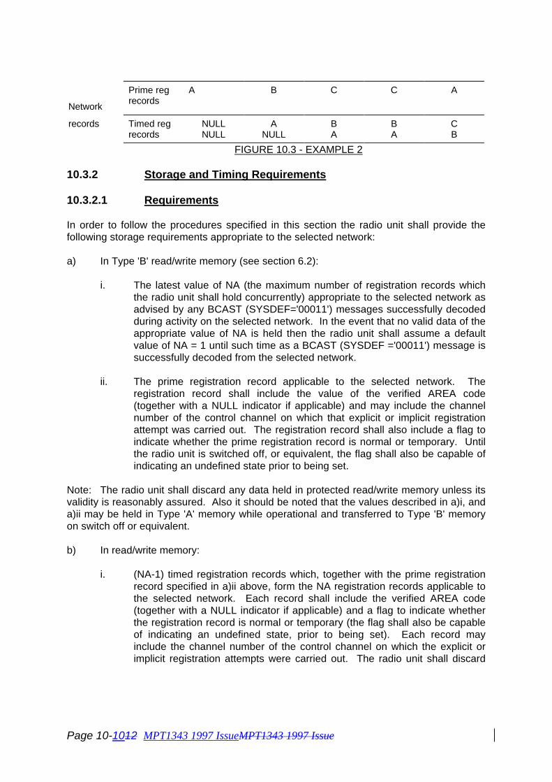
Page 10-1012 MPT1343 1997 IssueMPT1343 1997 Issue
Network
Prime regrecords
A B C C A
records Timed regrecords
NULLNULL
ANULL
BA
BA
CB
FIGURE 10.3 - EXAMPLE 2
10.3.2 Storage and Timing Requirements
10.3.2.1 Requirements
In order to follow the procedures specified in this section the radio unit shall provide thefollowing storage requirements appropriate to the selected network:
a) In Type 'B' read/write memory (see section 6.2):
i. The latest value of NA (the maximum number of registration records whichthe radio unit shall hold concurrently) appropriate to the selected network asadvised by any BCAST (SYSDEF='00011') messages successfully decodedduring activity on the selected network. In the event that no valid data of theappropriate value of NA is held then the radio unit shall assume a defaultvalue of NA = 1 until such time as a BCAST (SYSDEF ='00011') message issuccessfully decoded from the selected network.
ii. The prime registration record applicable to the selected network. Theregistration record shall include the value of the verified AREA code(together with a NULL indicator if applicable) and may include the channelnumber of the control channel on which that explicit or implicit registrationattempt was carried out. The registration record shall also include a flag toindicate whether the prime registration record is normal or temporary. Untilthe radio unit is switched off, or equivalent, the flag shall also be capable ofindicating an undefined state prior to being set.
Note: The radio unit shall discard any data held in protected read/write memory unless itsvalidity is reasonably assured. Also it should be noted that the values described in a)i, anda)ii may be held in Type 'A' memory while operational and transferred to Type 'B' memoryon switch off or equivalent.
b) In read/write memory:
i. (NA-1) timed registration records which, together with the prime registrationrecord specified in a)ii above, form the NA registration records applicable tothe selected network. Each record shall include the verified AREA code(together with a NULL indicator if applicable) and a flag to indicate whetherthe registration record is normal or temporary (the flag shall also be capableof indicating an undefined state, prior to being set). Each record mayinclude the channel number of the control channel on which the explicit orimplicit registration attempts were carried out. The radio unit shall discard
MPT1343 1997 IssueMPT1343 1997 Issue Page 10-111
any timed registration record held in read/write memory when a time TD haselapsed since the registration record was written to read/write memory.
ii. At least 8 different values of AREA sub-field of the received system identitycode verified when acquiring the control channel on which a registrationattempt by the radio unit has been denied. These shall be managed as aFIFO list: when the radio unit has a full list of entries, any further addition tothe list shall displace the earliest entry.
iii. The latest value of the REG parameter received on the control channel toindicate whether the control channel is in the normal or temporaryregistration mode (an undefined state shall be indicated prior to receipt ofREG within a session).
c) In read-only memory, which shall be set by network personalisation:
i. A value of the ZONE field which shall be designated as the 'home' ZONE ofthe radio unit.
10.3.2.2 Action on Switch off or Switch on or equivalent
Data held under 10.3.2.1 b) shall be discarded at some time between the radio unit beingswitched off and being made ready for service after being subsequently switched on. Forthese purposes a user-initiated change of selected network shall be regarded as beingequivalent to switching off the radio unit.
If, at switch-off (or equivalent), the prime registration record is currently labelled asundefined (see sections 10.3.4.1.1, 10.3.4.2.1, 10.3.5.1.1 and 10.3.5.2.1), then at sometime between the radio unit being switched off and being made ready for service afterbeing subsequently switched on, the prime registration record shall be labelled as normal.
10.3.2.3 Value of a NULL record
A NULL record contains the AREA code and a NULL indicator.
10.3.3 Action on confirmation of a control channel
A radio unit shall not make any attempt at random access until control channel confirmationhas been achieved, see 9.3.4.4.
When a radio unit confirms a control channel it shall then:
i. If the verified AREA code is zero, or the radio unit is personalised with a zerolength AREA field, or the radio unit is in fall-back mode, the radio unit shallnot seek to register by random access nor shall it create or alter anyregistration record. The radio unit shall note that registration is not requiredand is free to initiate calls.
Otherwise:
Page 10-1212 MPT1343 1997 IssueMPT1343 1997 Issue
ii. If the verified area code is in the list of denied registrations, the radio unitshall resume hunting (see section 9).
Otherwise:
iii. If the radio unit does not hold a successful registration record for the verifiedAREA code, the radio unit shall attempt to register by random access (seesection 10.3.4) according to normal rules (see !!7.3!!).
Otherwise:
iv. If the radio unit holds a successful registration record for the verified AREAcode it shall not attempt to register. If the radio unit is of a type which storesthe relevant channel number in each registration record and, if the storedchannel number is different from the current number, then the radio unit shallreplace the stored channel number in the record by the current channelnumber without otherwise affecting the registration record or associatedtimer.
Once confirmed on a control channel, the radio unit shall not transmit any message otherthan RQR, or an acknowledgement in response to an Ahoy with IDENT1 = REGI(!!8.2.2.4!!), until it holds a successful registration record relating to the verified AREA code(unless the verified AREA code is zero, or the radio unit is personalised with a zero lengthAREA field, or the radio unit is in the fall-back mode) with the exception regarding a requestfor the radio unit security number detailed in the next paragraph. If at any time whilst activeon a control channel the radio unit ceases to hold a successful registration record relatingto the verified AREA code, it shall refrain from transmitting any message other than RQR,or an acknowledgement in response to an Ahoy with IDENT1 = REGI (!!8.2.2.4!!), until asuccessful registration record relating to the verified AREA code is held (unless the verifiedAREA code is zero, or the radio unit is personalised with a zero length AREA field, or theradio unit is in the fall-back mode). Whilst restricted in its transmissions due to not holdingan appropriate registration record the radio unit shall obey any applicable messagesreceived, as required, provided that to do so does not involve transmitting on the controlchannel (other than RQR or and ACK to an AHY with IDENT1 = REGI).
If, having transmitted an RQR with the "Security Number Flag" set to '1', the radio unit shallbe prepared to respond to a request from the TSC consisting of an AHYC, Mode 2IDENT2=TSCI, DESC='000') with a SAMIS containing the radio unit security number (seeSection 7 item 8) before expecting an acknowledgement to the registration request. (Note:In earlier versions of MPT1327, RQR has a 3 bit RSVD field. Bit 3 of this field is nowassigned to the "Security Number Flag".)At any time that the radio unit holds a successful registration record relating to the verifiedAREA code, it is free to transmit any message conforming to the requirements of thisspecification.
10.3.4 Registration Procedures
10.3.4.1 Registration by Random Access
MPT1343 1997 IssueMPT1343 1997 Issue Page 10-131
When a radio unit determines that it is required to register, it shall attempt to do so byrandom access using the procedures defined in MPT 1327 section 8.2.2. Note that if theregistration is occasioned by the receipt of BCAST (SYSDEF = '00011'), then the actionsprescribed in section 10.3.7 c) or d) shall be performed prior to those defined below.
If the random access timeout TC expires and the radio unit has not sent a registrationrequest (!!8.2.2.2!!), the radio unit shall enter the control channel acquisition procedures(section 9).
Provided that the prime registration record is not already a NULL containing the sameAREA code as the currently verified AREA code, then immediately the radio unit transmitsits first registration request message by random access it shall:
a) change the prime registration record, whether or not it has a NULL indicatorappended to it, into a timed registration record with a newly started timer, deleting, ifnecessary, the timed registration record closest to expiry (see section 10.3.6), andthen,
b) write into its prime registration record the AREA code for the system to which it ismaking the request together with a NULL indicator.
Note that the requirements of this paragraph shall not apply to repeat transmissions of therequest message within the same registration attempt.
The action after transmitting a random access registration request shall be as specified insections 10.3.4.1.1 to 10.3.4.1.5.
10.3.4.1.1 Registration Accepted
The registration attempt shall be considered successful on receipt of ACK(QUAL = '0').The radio unit shall:
a) convert the NULL prime record to a successful prime registration record byremoving the NULL indicator, and
b) if the radio unit has received a REG parameter (see 10.3.7) since commencing thesession, it shall label the registration record as either normal or temporary,corresponding to the latest received value of REG. If the radio unit has not receiveda REG parameter (see 10.3.7) since commencing the session, it shall label theregistration record as undefined (see also 10.3.2.2 and 10.3.7).
10.3.4.1.2 Registration Denied
The registration attempt shall be considered denied on receipt of ACKX(QUAL = '0'). Theradio unit shall:
a) write the AREA code in the list of denied registration records (see section 10.3.2),
and

Page 10-1412 MPT1343 1997 IssueMPT1343 1997 Issue
b) enter the control channel acquisition procedures (see section 9).
10.3.4.1.3 Registration Failed
The registration attempt shall be considered to have been unsuccessful upon receipt ofACKX(QUAL='1').
The radio unit shall resume hunting, see 9.4.1(j), and after confirmimg a control channeland receiving a suitable Aloha message, shall re-commence a random access registrationattempt in accordance with section 8.2.2 of MPT1327.
Note that, until a successful registration is achieved, the radio unit shall not attempt totransmit other than RQR messages, or an acknowledgement in response to an Ahoy withIDENT1 = REGI (!!8.2.2.4!!), or a SAMIS in response to an AHYC Mode 2 demanding itssecurity number, but shall continue to obey any received messages, provided that to do sodoes not involve transmitting on the control channel (other than RQR, or an ACK to anAhoy with IDENT1 = REGI).
10.3.4.1.4 Registration Attempt Times Out
If the radio unit times out from waiting for further signalling for the registration (!!8.2.2.4!!),or cancels its wait state as defined in section 9.4.2, it shall enter the control channelacquisition procedures (section 9).
10.3.4.1.5 Registration Demand Received During a Random AccessRegistration Transaction
If, while waiting for a response to a random access registration request message, the radiounit receives an ALHR message individually addressed to it, the radio unit shall send aregistration request RQR in accordance with MPT 1327 section 8.3.2.1 a2 (the radio unitshall not send an emergency request RQE).
The action shall then be as defined in sections 10.3.4.1.1 to 10.3.4.1.4, and in sections 7.3and 8.2.2.2 of MPT 1327.
10.3.4.2 Registration on Demand
If, while confirmed on a control channel and not attempting to register by random access, aradio unit receives an applicable individually addressed ALHR, it shall write a NULL recordagainst the existing registration record for the currently verified AREA code and shallattempt to register, complying with the procedures defined in MPT 1327 section 8.3.2.
Provided that the prime registration record is not now a NULL containing the same AREAcode as the currently verified AREA code, then upon making a registration attempt (as aresult of a demand) the radio unit shall:
a) change the prime registration record, whether or not it has a NULL indicatorappended to it, into a timed registration record with a newly-started timer, deleting, if
MPT1343 1997 IssueMPT1343 1997 Issue Page 10-151
necessary, the timed registration record closest to expiry (see section 10.3.6), andthen,
b) write into its prime registration record the AREA code for the system to which it ismaking the request together with a NULL indicator.
The radio unit action after transmitting RQR upon demand, whilst not attempting to registerby random access, shall be as defined in sections 10.3.4.2.1 to 10.3.4.2.3.
Refer to Annex AN5 for more information regarding system compatibility issues.
10.3.4.2.1 Registration Accepted
On receipt of ACK(QUAL='0') the registration shall be considered accepted and the radiounit shall:
a) convert the NULL prime record to a successful registration record (by removing theNULL indicator), and
b) if the radio unit has received a REG parameter (see 10.3.7) since commencing thesession, it shall label the registration record as either normal or temporary,corresponding to the latest received value of REG. If the radio unit has not receiveda REG parameter (see 10.3.7) since commencing the session, it shall label theregistration record as undefined (see also 10.3.2.2 and 10.3.7).
10.3.4.2.2 Registration Denied
Registration is denied if ACKX(QUAL='0') is received. On receipt of this message the radiounit shall:
a) write the AREA code in the list of denied registration records, and
b) enter the control channel acquisition procedures (section 9).
10.3.4.2.3 No Acknowledgement Received
If no response is received within WAIT+1 slots, the radio unit shall make no consequentialchanges to its registration record. If, as a result of the action prescribed in 10.3.4.2, theradio unit has no registration record for the verified AREA code, then it shall attempt toregister by random access.
10.3.5 Implicit Registration
When a radio unit participates in a signalling transaction on a control channel for which itholds a timed registration record then, in the circumstances defined in this section, theradio unit is implicitly re-registered, and a prime registration record is created for the verifiedAREA code. Note that the requirements of this section apply only when the radio unit istuned to a control channel for which it holds a timed successful registration record and onlywhen the radio unit is in the normal operation mode (not in the fall-back mode).

Page 10-1612 MPT1343 1997 IssueMPT1343 1997 Issue
10.3.5.1 Implicit Registration of Calling Radio Unit
Transmission of a random access message, other than RQR, or RQQ hook signalling, mayresult in implicit registration, as defined in sections 10.3.5.1.1 to 10.3.5.1.4.
10.3.5.1.1 Implicit Registration is Successful
Implicit registration shall be considered successful if any of the following messagesapplicable to the call are received:
- ACK(QUAL='0')- ACK(QUAL='1') if cancellation of the call is requested- ACKV- ACKE(QUAL='0')- ACKT(QUAL='0')- ACKB(QUAL='0')- GTC
On receipt of any of these messages (unless the prime registration record now correspondsto the verified AREA code) the radio unit shall:
a) Delete the timed registration record corresponding to the verified AREA code (if therecord still exists), and
b) Convert the prime registration record to a timed registration record with a newlystarted timer, and
c) Create a prime registration record for the verified AREA code, and
d) If the radio unit has received a REG parameter (see 10.3.7) since commencing thesession, it shall label the new prime registration record as either normal ortemporary, corresponding to the latest received value of REG. If the radio unit hasnot received a REG parameter (see 10.3.7) since commencing the session, it shalllabel the registration record as undefined (see also 10.3.2.2 and 10.3.7).
If the prime registration record is a NULL for the verified AREA code, then on receipt ofthese messages the radio unit shall convert the prime record to a successful registrationrecord (by removing the NULL indicator).
10.3.5.1.2 Implicit Registration Failed
Implicit registration shall be considered failed if ACKX applicable to the call is received. Onreceipt of ACKX the radio unit shall make no consequential changes to the registrationrecords and shall return to the idle state.
10.3.5.1.3 Implicit Registration Times Out
If the radio unit times out from waiting for further signalling for a call (timeouts TA, TJ orTW), or cancels its wait state due to entering the control channel acquisition procedures(see 9.4.2), then (unless the prime registration record now corresponds to the verifiedAREA code, including if NULL) the radio unit shall:
MPT1343 1997 IssueMPT1343 1997 Issue Page 10-171
a) Convert the existing prime registration record to a timed registration record with anewly-started timer, deleting, if necessary, the timed registration record closest toexpiry, and
b) Create a NULL record as the prime registration record.
If the radio unit timed out from waiting (ie did not cancel its wait state), it shall then eitherreturn to the idle state or enter the control channel acquisition procedures (section 9).
10.3.5.1.4 Action at Switch-off or Equivalent
If, while the radio unit is waiting for further signalling for its call, the radio unit is switched off(or equivalent), or the user selects a different network, the radio unit shall (unless the primeregistration record now corresponds to the verified AREA code, including if NULL) create aNULL record as the prime registration record (note that the radio unit may be designed sothat no processing is required after switch-off has been initiated).
10.3.5.2 Implicit Registration of Called Radio Unit
Transmission by the radio unit of ACK(QUAL ='0') in response to an AHY message for anincoming traffic channel call (!!9.2.2.2A!!) may result in implicit registration as defined insections 10.3.5.2.1 to 10.3.5.2.4.
10.3.5.2.1 Implicit Registration is Successful
Implicit registration shall be considered successful if a GTC or AHYX message applicable tothe incoming call is received.
On receipt of either of these messages (unless the prime registration record nowcorresponds to the verified AREA code) the radio unit shall:
a) Delete the timed registration record corresponding to the verified AREA code (if therecord still exists and irrespective of whether the record is normal or temporary), and
b) Convert the prime registration record to a timed registration record with a newly-started timer, and
c) Create a prime registration record for the verified AREA code, and
d) If the radio unit has received a REG parameter (see 10.3.7) since commencing thesession, it shall label the new prime registration record as either normal ortemporary, corresponding to the latest received value of REG. If the radio unit hasnot received a REG parameter (see 10.7) since commencing the session, it shalllabel the registration record as undefined (see also 10.3.2.2 and 10.3.7).
10.3.5.2.2 Implicit Registration Failed
If, while waiting for further signalling for an incoming traffic channel call, the radio unitreceives an AHY message for a different incoming traffic channel call and sends

Page 10-1812 MPT1343 1997 IssueMPT1343 1997 Issue
ACK(QUAL ='0') or ACKI(QUAL ='0'), the radio unit shall make no consequential changesto the registration records and shall apply the procedures of 10.3.5.2 to the new AHY.
10.3.5.2.3 Implicit Registration Times Out
If the radio unit times out from waiting for further signalling for an incoming traffic channelcall (timeout TA) or cancels its wait state due to entering the control channel acquisitionprocedures (see 9.4.2), then (unless the prime registration record now corresponds to theverified AREA code, including if NULL) the radio unit shall:
a) change the prime registration record, whether or not it has a NULL indicatorappended to it, into a timed registration record with a newly started timer, deleting, ifnecessary, the timed registration record closest to expiry, and then,
b) write into its prime registration record the AREA code for the system on which it isverified together with a NULL indicator.
If the radio unit timed out from waiting (ie did not cancel its wait state), it shall then return tothe idle state.
10.3.5.2.4 Action on Switch-off or Equivalent
If, while the radio unit is waiting for further signalling for an incoming traffic channel call, theradio unit is switched off (or equivalent), or the user selects a different network, the radiounit shall (unless the prime registration record now corresponds to the verified AREA code,including if NULL) create a NULL record as the prime registration record (note that the radiounit may be designed so that no processing is required after switch-off has been initiated).
10.3.6 Registration Record Timeout
The timer for a registration record (timeout value TD) shall be started when the record isdisplaced from being prime registration record.
The radio unit shall delete any registration record (even a NULL record) displaced frombeing the prime registration record for which the time period TD has expired.
If the deletion on timeout occurs while the radio unit is active on a control channel, andresults in the radio unit having no successful registration record corresponding to thereceived confirmation AREA code, the unit shall attempt to explicitly register by randomaccess, see section 10.3.4.1.
10.3.7 Action on receiving broadcast registration parameters
a) If the received value of NA is smaller than the number of registration recordscurrently stored, the radio unit shall delete the excess number of records, retainingonly the prime registration record and (NA-1) most recently created timedregistration records.

MPT1343 1997 IssueMPT1343 1997 Issue Page 10-191
b) If the radio unit holds an undefined registration record for the verified AREA code,the record shall be labelled as either normal or temporary corresponding to thevalue of REG received.
c) If the radio unit receives REG ='0' while active on a control channel, it shall recordthat the channel is in the normal registration mode.
If the radio unit holds a temporary registration record for the verified AREA code, itshall delete that record and attempt to register by random access.
d) If the radio unit receives REG ='1' while active on a control channel, it shall recordthat the channel is in the temporary registration mode.
If the radio unit holds a normal registration record (not temporary) for the control channel,and the ZONE value of the verified system identity code differs from the 'home' ZONE ofthe radio unit, the radio unit shall label the registration record as temporary. Note that b), c)and d) shall apply to all registration records held by the radio unit, not only the primerecords.
10.3.8 Fall-back Mode
Any radio unit (whether or not it implements the fall-back mode option) which receives anALHF message on a control channel for which the verified AREA code corresponds to aregistration record, but for which the verified ZONE code does not match its home zone,shall label the registration record as temporary.
10.3.8.1 Entering Fall-back Mode
Upon entering fall-back mode (see 13.3) a radio unit shall continue to maintain registrationrecords. Whilst in the fall- back mode and confirmed on the fall-back channel, the radiounit shall not attempt to register by random access or make use of control channelmessages to implicity register; the radio unit is free to initiate and receive calls even if theunit does not have a registration record for the verified AREA code.
10.3.8.2 Leaving Fall-back Mode
Upon leaving the fall-back mode the radio unit shall attempt to register if required to bysections 10.3.3 or 10.3.7.

MPT1343 1997 Issue Page 11-1
11. CALL PROCESSINGIn this section, the section numbers have been formed by prefixing the section numbers ofMPT 1327 by "11.". Thus sub-sections here refer directly to, and should be read in parallelwith, sections of MPT 1327. The requirements of MPT 1327 are also mandatoryrequirements of this specification. Each sub-section below defines the requirements for thefacilities and functions relevant to the radio unit for call processing. These requirementsare categorised as follows:
Mandatory The radio unit shall implement the function or facility.
Standard Option If the radio unit implements the function, then it shall be implementedat least in the specified manner.
Available for If the TSC implements such a customised function, then ifCustomisation the radio unit implements the function it shall operatein the manner specified by the network operator of that TSC. Suchfunctions will not modify existing standardised functions. If the radiounit does not understand the customised function in the context ofsystem it is currently using, then it shall ignore that function. Theradio unit shall not infringe any of the requirements of section 5 ofMPT 1327.
Optional The radio unit may use the information or implement the facility at thediscretion of the manufacturer.
Informative The corresponding section within MPT 1327 is primarily informative orrelated only to TSC specification, with no requirements on the radiounit arising directly from the contents. Related requirements may beincluded in other sections, however.
The radio unit shall ignore those fields of received messages which it does not understand.
11.1 IntroductionInformative.
11.1.1 User Facilities
Informative.
11.1.1.1 Types of Call
Informative.
11.1.1.2 Making Calls
It shall be mandatory for the radio unit to be able to make calls to individual radio units andline connected units. The ability to make calls to the other destinations listed is a standardoption.
It shall be mandatory for the radio unit to be able to make interprefix speech calls, althoughthis does not necessarily require prefix number entry by the user (see section 8.2).
Page 11-2 MPT1343 1997 Issue
The requirements on the radio unit for the use of call progress information sent by the TSCfor confidence indication is defined in section 8.1.
11.1.1.3 Receiving Calls
The requirement to respond to correctly addressed incoming calls that are received ismandatory. This requirement includes interprefix calls. The response may, however, be arejection if, for example, a radio unit does not have a particular non-mandatory facility, or ifthe user has indicated that certain calls are to be rejected.
The implementation of a busy control is a standard option.
The implementation of a call back control is a standard option.
The implementation of a "ready for communication control" (RFCC) is mandatory.
Confidence indication requirements are specified in section 8.1.
11.1.1.4 Diverting Calls
Diversion of calls is a standard option. Automatic re-dial to the diversion IDENT is optional.
11.1.2 System Features and Facilities
11.1.2.1 System Dimensions
It shall be mandatory for the radio unit to be able to store in its personality any one of theaddresses in the full addressing range as its individual address. In addition it shall bemandatory for the radio unit to be able to store in its personality up to 4 of the addresses inthe full addressing range as its group addresses (see section 6).
11.1.2.2 System Control
Informative. See section 13 of this specification for details of fall-back operation, which is astandard option.
11.1.2.3 Call Handling
Informative. The requirements for security are defined in section 11.15.
MPT1343 1997 Issue Page 11-3
11.1.2.4 Multi-site Systems
Informative. The registration procedures are defined in Section 10 of this specification.
11.1.3 Guide to Some Key Protocol Aspects
Informative.
11.1.3.1 Control Channel Signalling Structure
Informative.
11.1.3.2 Control Channel Signalling Messages
Informative.
11.1.3.3 Random Access Protocol
11.1.3.3.1 Principle of Operation
Informative.
11.1.3.3.2 Features of the Random Access Protocol
Informative.
11.1.3.4 Addressing
Informative. The use of extended addressing is mandatory for a radio unit making a simplecall to a radio unit or line unit with a different prefix.
11.1.3.5 Examples of Signalling Sequences
Informative.
11.1.3.5.1 Example: Radio Unit Calls a Group
The ability to make group calls is a standard option.
11.1.3.5.2 Example: Radio Unit Calls a Unit with the Same Prefix
The ability for the radio unit to make such calls is mandatory.
11.1.3.5.3 Example: Radio Unit Calls a Unit with a Different Prefix
The ability for the radio unit to make such calls is mandatory.
11.1.3.5.4 Example: Radio Unit Sends a Short Data Message
The ability for the radio unit to make such calls is a standard option.

Page 11-4 MPT1343 1997 Issue
11.2 Definitions
The definitions listed in section 2 of MPT 1327 are consistent with those listed in section 3of this specification.
11.3 Signalling Formats
Informative. The requirements listed in this section apply only to prescribed signalling.Non-prescribed signalling is not covered by this specification.
11.3.1 Basic Format
Mandatory as specified.
11.3.1.1 LET
Mandatory as specified.
11.3.1.2 Preamble
Mandatory as specified.
11.3.1.3 Message
Mandatory as specified.
11.3.1.4 Hang-over Bit, H
Mandatory as specified.
11.3.2 Message Format
Mandatory as specified.
11.3.2.1 Codeword Synchronisation Sequence
Mandatory as specified.
11.3.2.1.1 Control Channel Codeword Synchronisation Sequence
Mandatory as specified.
11.3.2.1.2 Traffic Channel Codeword Synchronisation Sequence
Mandatory as specified.
11.3.2.2 Codewords
Mandatory as specified.
11.3.2.3 Encoding and Error Checking
The encoding is mandatory as specified.
MPT1343 1997 Issue Page 11-5
The radio unit shall not accept any codeword from which the derived syndrome and paritybit indicate that 3 or more hard errors have occurred in an error burst of length 6 bits orgreater.
The radio unit shall reject any codeword if it does not correct potential bit errors indicatedby the coset leader for the syndrome.
The radio unit need not perform error correction, although error correction may simplifyreceiver and modem design requirements in meeting the error performance requirements ofthe receiver specified in Appendix A.
11.3.3 Signalling Transmission Variants
The radio unit shall be designed to cope with the variants specified.
11.3.3.1 Single Message Format
Mandatory as specified.
11.3.3.2 Multiple Message Format on the Traffic Channel
Mandatory as specified.
11.3.3.3 Forward Control Channel Format
11.3.3.3.1 Basic Control Channel Format
Mandatory as specified.
11.3.3.3.2 Data Codeword Displacement
Mandatory as specified.
11.4 Addressing
The radio unit shall understand those special IDENTS and DUMMYI that are required bythe mandatory call procedures, and also those required by any standard options that areimplemented.

Page 11-6 MPT1343 1997 Issue
11.5 Codeword StructuresThe standardised messages which the radio unit shall understand are defined in thefollowing sections.
Standardised Fields
Mandatory as specified.
Reserved Fields
Mandatory as specified.
Spare Fields and Codewords
Available for Customisation in the manner specified.
11.5.1 System Codewords
11.5.1.1 Control Channel System Codeword (CCSC)
Mandatory to make use of the CCSC for slot synchronisation.
The use of the DCSC is a standard option.
11.5.1.2 Data Channel System Codeword (DCSC)
The use of the DCSC is a standard option.
11.5.2 General Address Codeword Structures
Informative.
11.5.3 List of Address Codewords
Messages received by the radio unit which it shall understand and take any mandatoryaction required:
GTCALH, ALHS, ALHX, ALHR, ALHFACK, ACKI, ACKQ, ACKX, ACKV, ACKT, ACKBACKE (if configured to send RQE messages)AHY, AHYX, AHYQ, AHYCMAINT, MOVE, CLEAR, BCAST
Messages received by the radio unit which it shall understand and take any mandatoryaction required if the unit is individually addressed, and for which it is a standard option forthe radio unit to use if not individually addressed:
ALHD, ALHE
Messages received by the radio unit which it is a standard option for the radio unit tounderstand:
MPT1343 1997 Issue Page 11-7
AHYDDACK +DAL, DACK+DALG, DACK+DALN, DACK+GO, DACKD, DACKZ, DAHY, DAHYX,DAHYZGTT, MARK, HEADRLA, SACK, SITH
Messages for which the functions are not yet defined (informative):
SAMO
Messages which the radio unit shall be required to send by the protocol (mandatory):
ACKI (QUAL = '0')ACK, ACKXRQS, RQX, RQR, RQQ (indicating hook status)MAINT (see section 11.5.5.4.2 for applicable messages)SAMIS
Messages which the radio unit may send in the standardised format if permitted by theprotocol (standard option):
ACKV, ACKBRQT, RQE, RQC, RQQ (other than for hook status)DACK+GO, DACKD, DACKZDRQG, DRQX, DRQZ, DRUGIRLA, RQD, SACK, SITHHEAD
Messages for which the functions are not yet defined (informative):
SAMIU
Reserved and spare message fields shall be as specified.
11.5.4 Go To Traffic Channel Message, GTC
Mandatory as specified.
11.5.5 Category '000' Messages
11.5.5.1 Aloha Messages (Type '00')
It is mandatory that the radio unit shall use the following received messages in makingrandom access attempts:
ALH, ALHS, ALHX, ALHR
It is a standard option that the radio unit shall use the following received messages inrandom access attempts:
ALHD, ALHE
Page 11-8 MPT1343 1997 Issue
It is mandatory for the radio unit to understand the ALHF message; it is a standard optionfor the radio unit to implement fall-back mode (see section 13).
Use of the WT, M, CHAN4 and N fields shall be mandatory when making use of any Alohamessage. The CHAN4 bits correspond to the least significant four bits of the 10 bit binaryrepresentation of the channel number of the control channel on which the message wasreceived(see section 5.1).
It is mandatory that the radio unit shall respond to all individually addressed Alohamessages (ie those addressed to that specific unit, see !!7.4.1!!).
11.5.5.2 Acknowledgement Messages (Type '01')
Messages received by the radio unit which it shall understand and take any mandatoryaction required:
ACK, ACKI, ACKQ, ACKX, ACKV, ACKT, ACKB
Messages received by the radio unit which it shall understand and take any mandatoryaction required if the radio unit is configured to send RQE messages:
ACKE
Messages which the radio unit shall send where required by the protocol (mandatory):
ACK, ACKX, ACKI (QUAL = '0')
Messages which the radio unit may send in the standardised format if permitted by theprotocol (standard option):
ACKV, ACKB
11.5.5.2.1 Acknowledgement Messages Sent by the TSC
Messages received by the radio unit which it shall understand and take any mandatoryaction required:
ACK, ACKI, ACKQ, ACKX, ACKV, ACKT, ACKBACKE (if configured to send RQE messages)
Use of the QUAL field of the received message is a standard option except where:
i. mandatory confidence indications are required in section 8.1;
ii. the protocol of MPT 1327 requires a different mandatory action based on theQUAL field.
Use of the diversion address or number of data codewords appended to ACKT(QUAL = '0') is optional. If IDENT1=PSTNGI in ACKT (QUAL='0') then the BCD digits in theappended data codeword (s) shall contain the full dialled string, less the leading 0.
ACKT (QUAL = '1') is reserved.
MPT1343 1997 Issue Page 11-9
11.5.5.2.2 Acknowledgements Sent by Radio Units
Messages which the radio unit shall send where required by the protocol (mandatory):
ACK (QUAL = '0' and QUAL = '1'), ACKX (QUAL = '0'), ACKI (QUAL = '0')
Messages which the radio unit may send in the standardised format if permitted by theprotocol (standard option):
ACKV (QUAL = '1'), ACKX (QUAL = '1'),ACKB (QUAL = '0' and QUAL = '1')
11.5.5.3 Type '10' Messages (Requests and Ahoys)
Informative.
11.5.5.3.1 Request Messages (Type '10')
Messages which the radio unit shall send where required by the protocol when making calls(mandatory):
RQS, RQX, RQRRQQ (for hook status)
Messages which the radio unit may send in the standardised format if permitted by theprotocol (standard option):
RQT, RQE, RQCRQQ (other than hook status)
11.5.5.3.1.1 Request "Simple" Call Message, RQS
Mandatory for RQS containing:
(IDENT1 = Ident or IPFIXI) andDT = '0' andLEVEL = '1' andEXT = '0' andFLAG1 = '0' andFLAG2 = '0'
Standard option for other combinations. For calls other than group calls or a shotaddressing call to a PABX extension, FLAG2 is se to zero, unless permittd by the network.
11.5.5.3.1.2 Request Codeword Free for Customisation
Section deleted in MPT 1327.
11.5.5.3.1.3 Call Cancel/Abort Transaction Request Message, RQX
Mandatory as specified.

Page 11-10 MPT1343 1997 Issue
11.5.5.3.1.4 Request Call Diversion Message, RQT
Standard option.
11.5.5.3.1.5 Request Emergency Call Message, RQE
Standard option.
11.5.5.3.1.6 Request to Register Message, RQR
Mandatory as specified.
The "Info" field shall be set to all zeros, unless permitted otherwise by the network.
11.5.5.3.1.7 Request Status Transaction, RQQ
Mandatory for indication of hook status (see MPT 1327 section 13). Standard optionotherwise.
11.5.5.3.1.8 Request to Transmit Short Data Message, RQC
Standard option.
11.5.5.3.2 Ahoy Messages (Type '10')
Messages received by the radio unit which it shall understand and take any mandatoryaction required:
AHY, AHYX, AHYQ, AHYC
11.5.5.3.2.1 General Availability Check Message, AHY
It is mandatory that the radio unit responds to an individually addressed AHY message.Use of the address in any data codeword appended to the AHY is a standard option.
11.5.5.3.2.2 Reserved Section
Informative.
11.5.5.3.2.3 Cancel Alert State Message, AHYX
Mandatory as specified.
11.5.5.3.2.4 Reserved Section
Informative.
11.5.5.3.2.5 Reserved Section
Informative.
11.5.5.3.2.6 Reserved Section
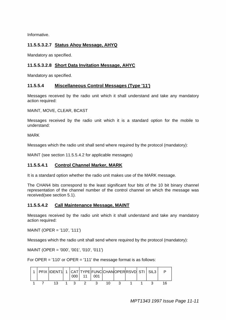
MPT1343 1997 Issue Page 11-11
Informative.
11.5.5.3.2.7 Status Ahoy Message, AHYQ
Mandatory as specified.
11.5.5.3.2.8 Short Data Invitation Message, AHYC
Mandatory as specified.
11.5.5.4 Miscellaneous Control Messages (Type '11')
Messages received by the radio unit which it shall understand and take any mandatoryaction required:
MAINT, MOVE, CLEAR, BCAST
Messages received by the radio unit which it is a standard option for the mobile tounderstand:
MARK
Messages which the radio unit shall send where required by the protocol (mandatory):
MAINT (see section 11.5.5.4.2 for applicable messages)
11.5.5.4.1 Control Channel Marker, MARK
It is a standard option whether the radio unit makes use of the MARK message.
The CHAN4 bits correspond to the least significant four bits of the 10 bit binary channelrepresentation of the channel number of the control channel on which the message wasreceived(see section 5.1).
11.5.5.4.2 Call Maintenance Message, MAINT
Messages received by the radio unit which it shall understand and take any mandatoryaction required:
MAINT (OPER = '110', '111')
Messages which the radio unit shall send where required by the protocol (mandatory):
MAINT (OPER = '000', '001', '010', '011')
For OPER = '110' or OPER = '111' the message format is as follows:
1 PFIX IDENT1 1 CAT000
TYPE11
FUNC001
CHAN OPER RSVD STI SIL3 P
1 7 13 1 3 2 3 10 3 1 1 3 16

Page 11-12 MPT1343 1997 Issue
Field definitions are as for MPT 1327 with the addition of:
STI - Site Indicator Flag. If non-zero then SIL3 holds the three least significant bitsof the SIL sub-field of the system identity code (SYS) currently beingpropagated by the system originating the message.
SIL3 - The three least significant bits of the SIL sub-field of the system identity code(SYS) currently being propagated by the system originating the message.
For STI = '0' then SIL3 = RSVD (RSVD = '000')
It is mandatory for the radio unit to understand and act on the messages:
MAINT (OPER = '110') (See also 11.9.2.3.7)
MAINT (OPER = '111') (See also 11.9.2.3.3)
It is mandatory for the radio unit to send these messages where required by the protocol:
MAINT (OPER = '000', '001', '010', '011')
For OPER = '110' or OPER = '111', the STI and SIL3 fields are reserved and shall be set tozero for MAINT messages transmitted by radio units.
11.5.5.4.3 Clear-Down Message, CLEAR
Mandatory as specified.
If the radio unit receives a CLEAR message with the CONT field set to '0000000000' thenthe radio unit shall either return to the last active control channel, or remain on thenominated fall-back channel if in fall-back mode (see Sections 9 and 13). The messageformat is as follows:
1 CHAN CONT 1 CAT000
TYPE11
FUNC010
STI SIL3 TSI SPARE REVS101010101010
P
1 10 10 1 3 2 3 1 3 1 1 12 16
Field definitions are as for MPT 1327 with the addition of:
STI - Site Indication Flag. If non-zero then SIL3 holds the three least significantbits of the SIL sub-field of the system identity code (SYS) currently beingpropagated by the system originating the message.
SIL3 - The three least significant bits of the SIL sub-field of the system identity codeappropriate to the system originating the message.
For STI = '0' then SIL3 = RSVD (RSVD = '000')
TSI - Time-shared control channel indicator. See section 9.
'0' - Time-shared control channels are not expected on channel number CONT.'1' - Time-shared control channels may be encountered on channel number
CONT.
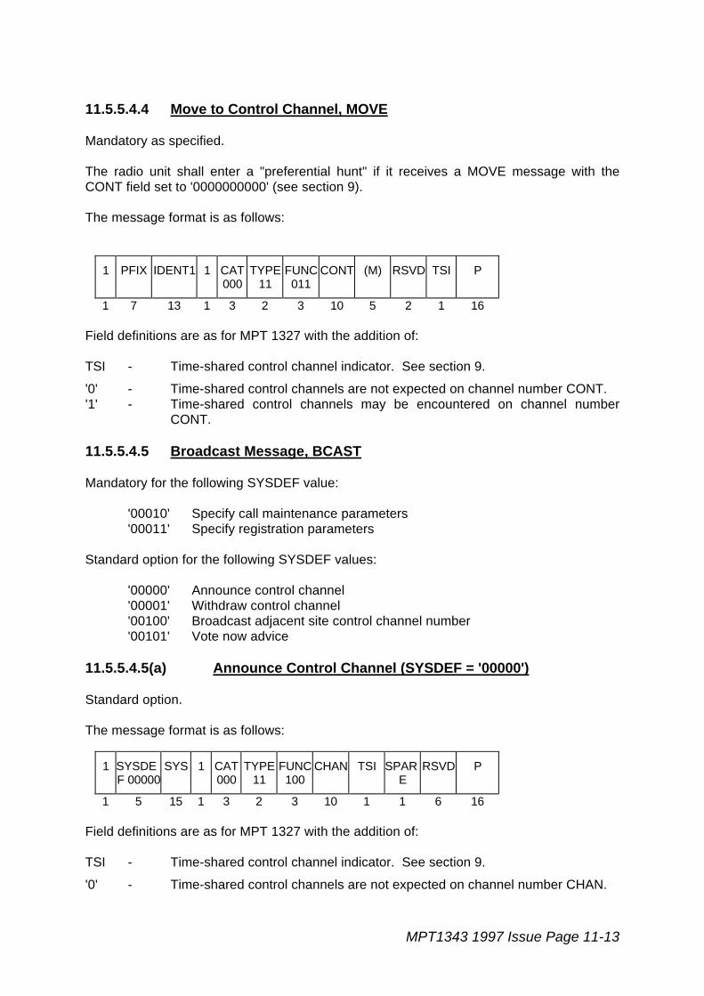
MPT1343 1997 Issue Page 11-13
11.5.5.4.4 Move to Control Channel, MOVE
Mandatory as specified.
The radio unit shall enter a "preferential hunt" if it receives a MOVE message with theCONT field set to '0000000000' (see section 9).
The message format is as follows:
1 PFIX IDENT1 1 CAT000
TYPE11
FUNC011
CONT (M) RSVD TSI P
1 7 13 1 3 2 3 10 5 2 1 16
Field definitions are as for MPT 1327 with the addition of:
TSI - Time-shared control channel indicator. See section 9.
'0' - Time-shared control channels are not expected on channel number CONT.'1' - Time-shared control channels may be encountered on channel number
CONT.
11.5.5.4.5 Broadcast Message, BCAST
Mandatory for the following SYSDEF value:
'00010' Specify call maintenance parameters'00011' Specify registration parameters
Standard option for the following SYSDEF values:
'00000' Announce control channel'00001' Withdraw control channel'00100' Broadcast adjacent site control channel number'00101' Vote now advice
11.5.5.4.5(a) Announce Control Channel (SYSDEF = '00000')
Standard option.
The message format is as follows:
1 SYSDEF 00000
SYS 1 CAT000
TYPE11
FUNC100
CHAN TSI SPARE
RSVD P
1 5 15 1 3 2 3 10 1 1 6 16
Field definitions are as for MPT 1327 with the addition of:
TSI - Time-shared control channel indicator. See section 9.
'0' - Time-shared control channels are not expected on channel number CHAN.
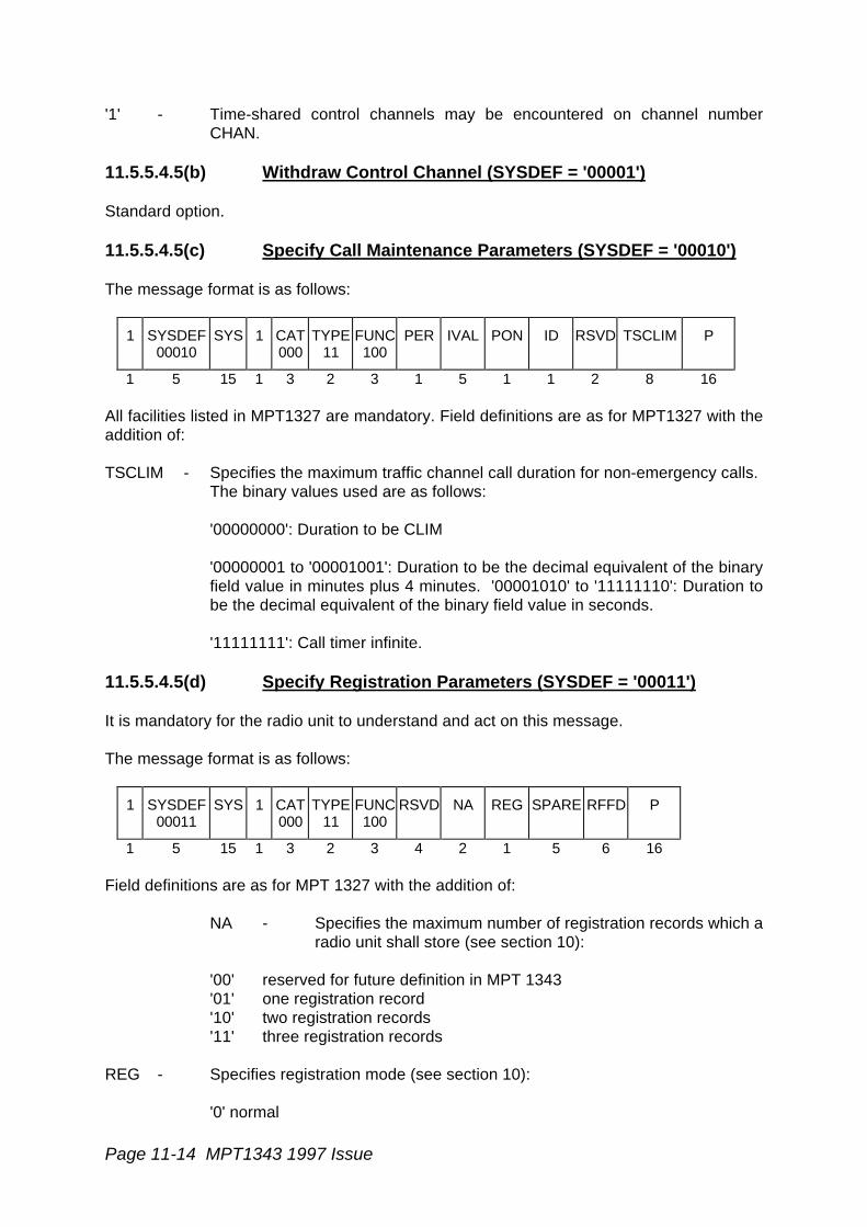
Page 11-14 MPT1343 1997 Issue
'1' - Time-shared control channels may be encountered on channel numberCHAN.
11.5.5.4.5(b) Withdraw Control Channel (SYSDEF = '00001')
Standard option.
11.5.5.4.5(c) Specify Call Maintenance Parameters (SYSDEF = '00010')
The message format is as follows:
1 SYSDEF00010
SYS 1 CAT000
TYPE11
FUNC100
PER IVAL PON ID RSVD TSCLIM P
1 5 15 1 3 2 3 1 5 1 1 2 8 16
All facilities listed in MPT1327 are mandatory. Field definitions are as for MPT1327 with theaddition of:
TSCLIM - Specifies the maximum traffic channel call duration for non-emergency calls.The binary values used are as follows:
'00000000': Duration to be CLIM
'00000001 to '00001001': Duration to be the decimal equivalent of the binaryfield value in minutes plus 4 minutes. '00001010' to '11111110': Duration tobe the decimal equivalent of the binary field value in seconds.
'11111111': Call timer infinite.
11.5.5.4.5(d) Specify Registration Parameters (SYSDEF = '00011')
It is mandatory for the radio unit to understand and act on this message.
The message format is as follows:
1 SYSDEF00011
SYS 1 CAT000
TYPE11
FUNC100
RSVD NA REG SPARE RFFD P
1 5 15 1 3 2 3 4 2 1 5 6 16
Field definitions are as for MPT 1327 with the addition of:
NA - Specifies the maximum number of registration records which aradio unit shall store (see section 10):
'00' reserved for future definition in MPT 1343'01' one registration record'10' two registration records'11' three registration records
REG - Specifies registration mode (see section 10):
'0' normal
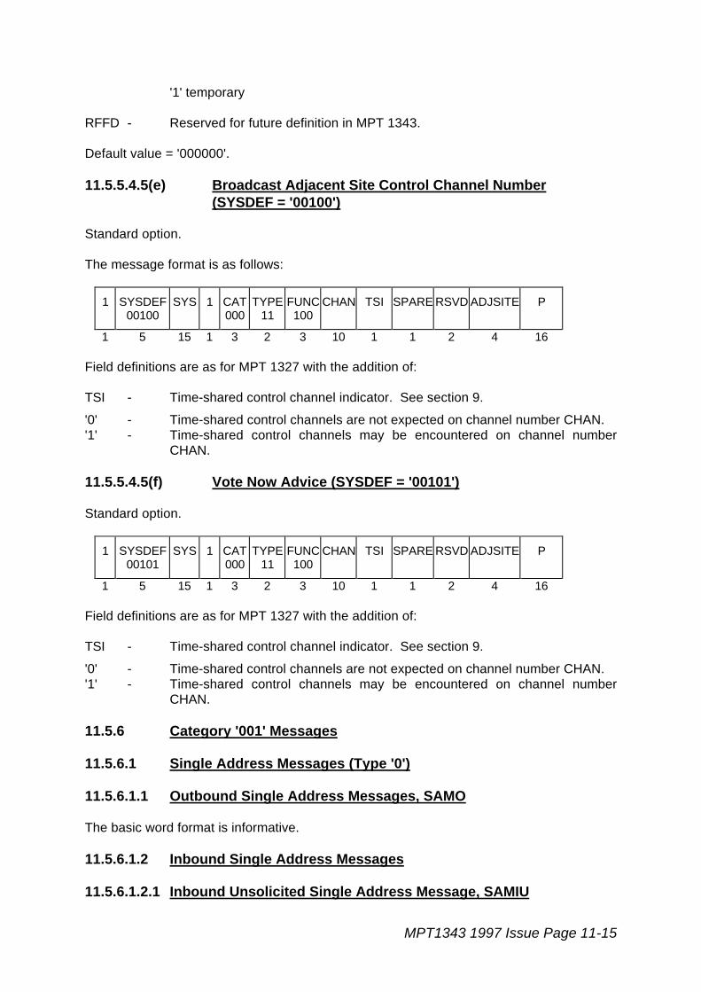
MPT1343 1997 Issue Page 11-15
'1' temporary
RFFD - Reserved for future definition in MPT 1343.
Default value = '000000'.
11.5.5.4.5(e) Broadcast Adjacent Site Control Channel Number(SYSDEF = '00100')
Standard option.
The message format is as follows:
1 SYSDEF00100
SYS 1 CAT000
TYPE11
FUNC100
CHAN TSI SPARE RSVD ADJSITE P
1 5 15 1 3 2 3 10 1 1 2 4 16
Field definitions are as for MPT 1327 with the addition of:
TSI - Time-shared control channel indicator. See section 9.
'0' - Time-shared control channels are not expected on channel number CHAN.'1' - Time-shared control channels may be encountered on channel number
CHAN.
11.5.5.4.5(f) Vote Now Advice (SYSDEF = '00101')
Standard option.
1 SYSDEF00101
SYS 1 CAT000
TYPE11
FUNC100
CHAN TSI SPARE RSVD ADJSITE P
1 5 15 1 3 2 3 10 1 1 2 4 16
Field definitions are as for MPT 1327 with the addition of:
TSI - Time-shared control channel indicator. See section 9.
'0' - Time-shared control channels are not expected on channel number CHAN.'1' - Time-shared control channels may be encountered on channel number
CHAN.
11.5.6 Category '001' Messages
11.5.6.1 Single Address Messages (Type '0')
11.5.6.1.1 Outbound Single Address Messages, SAMO
The basic word format is informative.
11.5.6.1.2 Inbound Single Address Messages
11.5.6.1.2.1 Inbound Unsolicited Single Address Message, SAMIU

Page 11-16 MPT1343 1997 Issue
The basic word format is informative.
11.5.6.1.2.2 Inbound Solicited Single Address Message, SAMIS
Mandatory for Mode 1, DESC = '000' (Interprefix calls).Mandatory for Mode 2, DESC = '000' (Serial number transfer).
Standard option otherwise.
11.5.6.2 Short Data Message Header, HEAD (Type '1')
Standard option.
11.5.7 Codewords applicable to Standard Data
11.5.7.1 Request Standard Data Communication RQD
Standard option.
11.5.7.2 Availability Check for Standard Data AHYD
Standard option.
11.5.7.3 Go to Transaction GTT
Standard option.
11.5.7.4 Standard Data Random Access Radio Unit GeneralInformation DRUGI
Standard option.
11.5.8 Codewords applicable to Standard Data Transactions
11.5.8.1 Standard Data General Purpose Acknowledgement DACKD
Standard option.
11.5.8.2 Standard Data Codeword DACK containing Submessages DAL,DALG, DALN or GO
Standard option.
11.5.8.3 Standard Data Acknowledgement for Expedited Data DACKZ
Standard option.
11.5.8.4 Standard data General Ahoy DAHY
Standard option.

MPT1343 1997 Issue Page 11-17
11.5.8.5 Standard Data Ahoy containing expedited Data DAHYZ
Standard option.
11.5.8.6 Standard Data Ahoy for closing a Trans DAHYX
Standard option.
11.5.8.7 Repeat last ACK - RLA
Standard option.
11.5.8.8 Repeat Group Message DRQZ
Standard option.
11.5.8.9 Request containing expedited Data DRQZ
Standard option.
11.5.8.10 Request to close a Transaction DRQX
Standard option.
11.5.8.11 Standard Data Selective Acknowledgement Header SACK
Standard option.
11.5.8.12 Standard Data Address codeword for a Dataitem SITH
Standard option.
11.6 Channel Discipline
Informative.
11.6.1 Channel Discipline for TSC
11.6.1.1 Control Channel Discipline for TSC
Informative.
11.6.1.2 Traffic Channel Discipline for TSC
11.6.1.2.1 Monitoring
Informative.
11.6.1.2.2 Signal Timing
Informative.

Page 11-18 MPT1343 1997 Issue
11.6.1.3 Data Channel Discipline for TSC
Informative.
11.6.1.3.1 Monitoring
Informative.
11.6.1.3.1 Signal Timing
Informative.
11.6.2 Channel Discipline for Radio Units
11.6.2.1 Control Channel Discipline for Radio Units
11.6.2.1.1 Control Channel Acquisition
Mandatory where specified. The radio unit shall also meet the requirements of section 9 ofthis specification.
11.6.2.1.2 Retaining a Control Channel
Mandatory as specified, where:
- an applicable system identity code is any system identity code where bits 1-12 differ from the verified value or where bits 13-15 (LAB) are a value whichdoes not permit access to the control category assigned to the radio unit;
- appropriate codewords are CCSC's and, if the radio unit is equipped toreceive them, MARK messages;
- a correct value of the system identity code is one in which bits 1-12 of theSYS field from a received appropriate codeword match bits 1-12 of theverified value value and bits 13-15 (LAB) are a value which permits accessto the control category assigned to the radio unit.
The radio unit shall also meet the requirements of section 9 of this specification.
11.6.2.1.3 Signal Timing
Mandatory as specified.
The reception-to-reception retuning time limits stipulated in MPT 1327, [6.2.1.3], [6.2.2.1],[7.4.2], [9.2.2.5], [9.2.3.4] and [9.2.3.8] all refer to the time between the end of the relevantinvoking codeword and the start of the last 16 bits of the preamble to the standard datamessage on the new channel. The only requirement is to be able to decode such amessage.
Time limits for satisfactory reception of speech or non-standard data are not specified.
MPT1343 1997 Issue Page 11-19
11.6.2.2 Traffic Channel Discipline for Radio Units
11.6.2.2.1 Monitoring
Mandatory as specified.
For definition of the re-tuning time limits, see 11.6.2.1.3.
11.6.2.2.2 Signal Timing
Mandatory as specified.
11.6.2.2.2.1 Radio Unit Response
Mandatory as specified.
11.6.2.2.2.2 Unsolicited Transmission that Requires a Response
Standard option.
11.6.2.3 Data Channel Discipline for Radio Units
Standard Option
11.6.2.3.1 Monitoring
Standard Option
11.6.2.3.2 Signal Timing
Standard Option
11.7 Random Access Protocol
Informative.
11.7.1 The Principle
Informative.
11.7.2 TSC Random Access Facilities
11.7.2.1 Marking Random Access Frames
Informative.
11.7.2.2 Subdividing the Radio Unit Population
Informative.
Page 11-20 MPT1343 1997 Issue
11.7.2.3 Inviting Specific Types of Random Access Message
Informative.
11.7.2.4 TSC Responses
Informative.
11.7.2.5 Withdrawing Slots from Frames
Informative.
11.7.3 Radio Unit Random Access Protocol
Mandatory as specified.
11.7.3.1 Checking Subsets of the Radio Unit Population
Mandatory as specified.
11.7.3.2 Checking the Aloha Function
Mandatory as specified. The recognition of ALHF is mandatory; the implementation of thefall back mode is a standard option (see section 13).
11.7.3.3 Frames Defined by Aloha Numbers
Mandatory as specified.
11.7.3.4 First Try Option
Standard Option as stated.
11.7.3.5 Choosing a Slot from a New Frame
Mandatory as specified.
11.7.3.6 Check for Withdrawn Slot
Mandatory as specified. It is mandatory for the radio unit not to make a random accesswhen a codeword is not decodable (or no signal is received) (item d. of MPT 1327section 7.3.6).
11.7.3.7 Noting the Response Delay
Mandatory as specified. The required value of parameter NW is defined in Appendix B ofthis specification.
11.7.3.8 Retry Decision and Time-outs

MPT1343 1997 Issue Page 11-21
Mandatory as specified. Requirements for confidence indications are given in section 8.1.The required values of timeout and default parameters listed are defined in section 6 andAppendix B of this specification.
11.7.4 Related Procedures for all Radio Units on a Control Channel
11.7.4.1 Individually Addressed Aloha Message
Mandatory as specified.
11.7.4.2 MOVE Message
Mandatory as specified (see also section 11.5.5.4.4). For definition of the retuning timelimits, see 11.6.2.1.3.
11.8 Registration Procedures
Informative. Mandatory requirements for registration are specified in section 10 of thisspecification.
11.8.1 Registration Facilities
Informative. The function of ALHF is specified in sections 9 and 13.
11.8.2 Procedures for Registration by Random Access
11.8.2.1 TSC Procedures
Informative.
11.8.2.1.1 Responses to a Random Access RQR Message
Informative.
11.8.2.1.2 Acknowledgements Sent to Indicate Progress of Registration
Informative.
11.8.2.1.3 TSC Time-out
Informative.
11.8.2.2 Radio Unit Procedures for Registration by Random Access
11.8.2.2.1 Criteria for Registration
Mandatory where specified. The requirements placed on the radio unit as regardsregistration are given in section 10. The radio unit shall not attempt random access to asystem unless that system is identified in its personality (see section 6). Where a systemrequires a radio unit to register, the radio unit shall be required to register successfullybefore attempting to make any calls.

Page 11-22 MPT1343 1997 Issue
11.8.2.2.2 Registration Request and Valid Responses
Mandatory where specified. The required values of timeout and default parameters listedare defined in section 6 and Appendix B of this specification. The radio unit shall set theINFO field to all zeros, unless permitted otherwise by the network.
11.8.2.2.3 Acknowledgement Received
Mandatory where specified. The action that the radio unit shall take when registration isdenied is defined in section 10 of this specification.
11.8.2.2.4 Time-out after Waiting
Mandatory where specified. The action that the radio unit shall take when registration isdenied is defined in section 10 of this specification.
11.8.3 Procedures for Registration on Demand
11.8.3.1 TSC Procedures for Demanding Registration
Informative.
11.8.3.2 Radio Unit Procedures for Registration on Demand
11.8.3.2.1 Individually Addressed ALHR Message
Items a1, a2: mandatory as specified. Item b: all radio units shall have the capability toregister, and hence the radio unit shall respond with RQR in this case. Item c. is notapplicable.
11.8.3.2.2 Response to RQR sent on Demand
Mandatory as specified. Additional mandatory requirements are placed on the radio unit insection 10 of this specification.
11.9 Basic Call Procedures
Informative.
It shall be mandatory for the radio unit to be able to make "simple" calls to the followingdestinations:
Radio units and line units with the same prefix.Radio units and line units with a different prefix.
It is a standard option for the radio unit to make "simple" calls to destinations other thanthose listed above.
It is a standard option for a radio unit to make the following calls:
Calls to a group.Calls to all units on a system.

MPT1343 1997 Issue Page 11-23
11.9.1 Basic Call Procedures for TSC
Informative.
11.9.1.1 Basic TSC Procedures for Setting Up Calls
11.9.1.1.1 Responses to a Short Addressing RQS Message
Informative.
11.9.1.1.2 Responses to an Extended Addressing RQS Message
Informative.
11.9.1.1.3 Instructions to Send Extended Address Information
Informative.
11.9.1.1.4 Acknowledgements Sent to a Calling Unit to Indicate Progress ofa Simple Call
Informative.
11.9.1.1.5 Availability Check on Called Radio Unit
Informative.
11.9.1.1.6 Availability Check for Calls to PABX Extensions and PSTNDestinations
Informative.
11.9.1.1.7 Availability Check on Requesting Radio Unit
Informative.
11.9.1.1.8 Call Cancellation
Informative.
11.9.1.1.9 Call Amalgamation
Informative.
11.9.1.1.10 Queue Management and Queue Time-out
Informative.
11.9.1.1.11 Resolving Call Conflicts
Page 11-24 MPT1343 1997 Issue
Informative.
11.9.1.1.12 Traffic Channel Allocation
Informative.
11.9.1.2 Basic TSC Procedures for Maintenance and Clear-Down of Calls
Informative.
11.9.1.2.1 Call Maintenance Options
Informative.
11.9.1.2.2 Availability Check on Traffic Channel
Informative.
11.9.1.2.3 Disabling User Transmission
Informative.
11.9.1.2.4 Allocating Replacement Traffic Channel
Informative.
11.9.1.2.5 Clearing Down Unwanted Radio Units During a Call
Informative.
11.9.1.2.6 Call Cleardown
Informative.
11.9.2 Basic Call Procedures for Radio Units
Mandatory where specified.
It is a mandatory for the radio unit to be fitted with a "ready for communication control"(RFCC).
11.9.2.1 Procedures for Radio Units Making Simple Calls
Mandatory where specified.
It is a standard option for a radio unit to make calls to a PABX or PSTN destination.
11.9.2.1.1 Request for a Simple Call
Mandatory as specified.

MPT1343 1997 Issue Page 11-25
It shall be mandatory for the radio unit to be able to make simple calls to common prefixand interprefix destinations.
It is a standard option for a radio unit to make data calls.
11.9.2.1.2 Valid Responses to Short Addressing RQS
Mandatory as specified.
11.9.2.1.3 Valid Responses to Extended Addressing RQS
Mandatory as specified.
11.9.2.1.4 Acknowledgement Received
Mandatory as specified.
Requirements for confidence indications are given in section 8.1. The radio unit shall makean indication to the user following receipt of ACKB (QUAL='0').
The facility to cancel a call accepted for call back by use of an RQQ message(STATUS = '11111') is a standard option.
Diversion requests (RQT) and use of diversion information are a standard option.Automatic re-dial to the diversion IDENT is optional.
11.9.2.1.5 Availability Check and Channel Allocation for Own Call
Mandatory as specified.
11.9.2.1.6 Time-out after Waiting
Mandatory as specified. The requirements for confidence indications are given insection 8.1.
11.9.2.1.7 Call Cancellation
Mandatory. It shall be possible for the user to cancel the call. The requirements forconfidence indications are given in section 8.1.
11.9.2.2 Basic Procedures for All Radio Units on a Control Channel
Informative.
11.9.2.2.1 Instruction to Send Address Information or Data Message
Mandatory for the following function:
Interprefix calls.
Standard option for the other transaction types listed.
Page 11-26 MPT1343 1997 Issue
11.9.2.2.2 Availability Check on Called Radio Unit
Mandatory where specified. It is optional whether the radio unit indicates the IDENT of thecaller to the user. It is optional whether the radio unit makes a distinct indication for anemergency call.
If, while waiting for an incoming traffic channel call, a radio unit receives a repeat AHY, andthe user has already activated the RFCC, the unit shall not re-alert the user.
In the event of an incoming traffic channel call (IDENT2 = Ident(1-8100), INCI, IPFIXI,PSTNGI or PABXI) the unit shall respond with one of ACK(QUAL='0'), ACKI(QUAL='0'),ACKB(QUAL='0'), ACKB(QUAL='1'), ACKV(QUAL='1') or ACKX(QUAL='0') in accordancewith MPT 1327. In addition, the radio unit shall only respond with ACKX(QUAL='0') if oneof the following conditions is met:
i. Bit D of the received AHY message is '0' and the unit is not accepting speech calls.
ii. Bit D of the received AHY message is '1' and the unit is not accepting or not readyfor data calls (see section 12).
The radio unit shall not accept a call for call back (using ACKB(QUAL='0')) unless it hasfacilities for making the return call.
It is mandatory for the radio unit to send RQQ off-hook/on-hook signalling.
As a standard option, the radio unit may respond to AHY, bit CHECK='1', with ACK(QUAL='0'). This option shall only be "enabled" by network personalisation and the defaultstate shall be "disabled".
11.9.2.2.3 Availability Check on Requesting Radio Unit
Mandatory as specified.
11.9.2.2.4 Cancelling Alert/Waiting State of Called Unit
Mandatory where specified.
The requirements for confidence indications are given in section 8.1.
11.9.2.2.5 Traffic Channel Allocation
Mandatory as specified. User indication of calling IDENT is optional. For definition of theretuning time limits, see 11.6.2.1.3.
11.9.2.2.6 Storing Call Maintenance Parameters
Mandatory as specified.
It is an option for radio units to store the value of TSCLIM from the last decodable BCAST,SYSDEF='00010' message received in read/write memory (see 11.5.5.4.5 c).
11.9.2.3 Procedures for all Radio Units on an Allocated Traffic Channel
Mandatory as specified.
MPT1343 1997 Issue Page 11-27
11.9.2.3.1 Call Maintenance Messages
For values of NPON=1 and NPOFF=1 : mandatory as specified.
For values of NPON>1 or NPOFF>1 : standard option.
11.9.2.3.2 Availability Check on Traffic Channel
Section A) Mandatory as specified
Section B) Standard Option
11.9.2.3.3 Disabling User Transmission
See also 11.5.5.4.2.
If the radio unit on a traffic channel receives a MAINT (OPER = '111') message with the STIflag equal to zero then:
i. the SIL3 field = RSVD and has no meaning;
ii. the radio unit shall understand and take any mandatory action required.
If the radio unit on a traffic channel receives a MAINT (OPER ='111') message with the STIflag NOT equal to zero, then:
i. the user transmission shall only be inhibited if the SIL3 field matches thethree least significant bits of the verified SIL code.
11.9.2.3.4 Replacement of Traffic Channel
Mandatory where specified.
For definition of the retuning time limits, see 11.6.2.1.3.
The radio unit shall meet the requirements of any prearrangement made as regards thesending of periodic messages during data calls .
11.9.2.3.5 Going "on-hook" on Traffic Channel
Mandatory as specified.
11.9.2.3.6 Time-outs on Traffic Channel
For values of NPON=1 and NPOFF=1: mandatory where specified.
For values of NPON>1 or NPOFF>1: standard option. The requirements for confidence indications are given in section 8.1.
Page 11-28 MPT1343 1997 Issue
The definition of inactivity that shall be used in this section of MPT 1327 is that a radio unitis considered inactive on a traffic channel when it is not transmitting and the received audiois muted because the receiver quieting is insufficient.
It is an option for radio units to incorporate a maximum call duration timer. This timer shallbe initialised immediately that the radio unit has tuned to a designated forward trafficchannel following receipt of a GTC message in accordance with !!9.2.2.5!! (unless inhibitedby the latest received value of TSCLIM, see below). The timer shall remain in operation foras long as the radio unit remains tuned to either the forward or return channel of thedesignated traffic channel or any other traffic channel to which the radio unit may bedirected by subsequent GTC messages in accordance with !!9.2.3.4!! but shall becancelled when the radio unit tunes to a control channel in accordance with !!9.2.3.5!!,!!9.2.3.6!!, !!9.2.3.7!! or !!9.2.3.8!!.
Upon expiry of the maximum call duration timer the radio unit shall:
i) Mute the audio.
ii) If the radio unit is transmitting it shall send one or more Pressel Off messages toindicate the end of the item in accordance with !!9.2.3.1!!.
iii) Send ND1 or ND2 Disconnect messages if its individual address is PFIX/IDENT1 orPFIX/IDENT2 from the GTC (as in section !!9.2.3.5!!).
iv) Cease transmission on the traffic channel, indicate the end of the call to the user inaccordance with 8.1.3.8 and enter the control channel acquisition procedures (seesection 9).
The radio unit may also use the call duration timer to indicate to the user that the aboveaction is imminent, at some time prior to the action being carried out.
The call duration timer shall expire after a period as determined below:
- Upon acquiring a new control channel and until a BCAST (SYSDEF='00010')message has been received, the period shall be CLIM.
- If at least one decodable BCAST (SYSDEF='00010') message has beenreceived by the radio unit since the start of the session or since acquiring anew control channel, the period shall be as indicated by the value of TSCLIMreceived in the last decodable BCAST (SYSDEF='00010') message (see11.5.5.4.5c) unless that value of TSCLIM is '00000000' when the period shallbe CLIM or is '11111111' when the maximum call duration timer shall beinhibited.
- If the radio unit has tuned to the traffic channel as a result of receiving aGTC message whilst waiting for signalling for an emergency call followingthe receipt of an AHY message with bit E set to '1' or following thetransmission of RQE, the period shall be CLIME.
If the radio unit transmits an item that reaches the maximum permitted duration TT then itshall mute the audio and shallas a default satisfy the procedures defined in !!9.2.3.6.A!!
MPT1343 1997 Issue Page 11-29
As an alternative !!9.2.3.6.B!! may be activated during personalisation of the radio unitusing the TT flag defined in Table 6.1 (Item nn)
Page 11-30 MPT1343 1997 Issue
11.9.2.3.7 "Selective" Clear-Down Message: MAINT with OPER='110'
See also 11.5.5.4.2.
The requirements for confidence indications are given in section 8.1.
If a radio unit on a traffic channel receives a MAINT (OPER ='110') with the STI flag equalto zero then:
i. the SIL3 field = RSVD and has no meaning;
ii. the radio unit shall understand and take any mandatory action required.
If the radio unit on a traffic channel receives a MAINT (OPER ='110') message with the STIflag NOT equal to zero, then:
i. the radio unit shall clear down only if the SIL3 field matches the three leastsignificant bits of the verified SIL code.
11.9.2.3.8 CLEAR Message
If a radio unit on a traffic channel receives a clear-down message CLEAR with the STI flagequal to zero
and
i. channel number (CHAN) equal to the number of the traffic channel
and
ii. field REVS equal to '101010101010',
then it shall immediately mute the audio and move to the forward control channel indicatedby the field CONT in the CLEAR message (to be capable of receiving within 35 ms after theend of the CLEAR address codeword) and may indicate to the user that the call has ended.
If a radio unit on a traffic channel receives a clear-down message CLEAR with the STI flagNOT equal to zero
and
i. channel number (CHAN) equal to the number of the traffic channel
and
ii. field REVS equal to '101010101010'
and
iii. the SIL3 field matches the three least significant bits of the verified SIL sub-field,
MPT1343 1997 Issue Page 11-31
then it shall immediately mute the audio and move to the forward control channel indicatedby the field CONT in the CLEAR message (to be capable of receiving within 35 ms after theend of the CLEAR address codeword) and may indicate to the user that the call has ended.
If the field CONT is set to '0000000000' then the radio unit shall either return to the lastactive control channel , or remain on the nominated fall-back channel if in fall-back mode.
The requirements for confidence indications are given in section 8.1.
11.10 Emergency Call Procedures
Standard option.
Other modes of customised emergency service are not precluded.
11.10.1 Standard Emergency Call Procedures for TSC
Entire subsection: informative.
11.10.2 Standard Emergency Call Procedures for Radio Units
Entire subsection: standard option.
Standard emergency call procedures on a traffic channel are defined in MPT 1327section 9.2.3.
11.11 Include Call Procedures
Standard option.
11.11.1 TSC Procedures for Include Calls
Entire subsection: informative.
11.11.2 Procedures for Radio Units Requesting Include
Entire subsection: standard option.
11.11.3 Procedures for All Radio Units on an Allocated Traffic Channel
11.11.3.1 Instruction to Send Extended Address Information
Standard option.
11.12 Call Diversion Procedures
Standard option.
11.12.1 TSC Procedures for Call Diversion Requests
Entire subsection: informative.
Page 11-32 MPT1343 1997 Issue
11.12.2 Procedures for Radio Units Requesting Call Diversion
Entire subsection: standard option.
11.13 Status Message Procedures
Entire section: procedures involving RFCC signalling are mandatory.It is mandatory that the radio unit is able to recognise and respond to the AHYQ message(refer to MPT 1327 section 13.2.3).Otherwise: standard option.
11.14 Short Data Message Procedures
Entire section: standard option.
11.15 Data Interrogation Procedures
Informative.
11.15.1 Data Interrogation Procedures for TSC
11.15.1.1 Data Interrogation on a Control Channel
Informative.
11.15.1.2 Data Interrogation on a Traffic Channel
Informative.
11.15.2 Procedures for All Radio Units
It is a mandatory requirement that radio units shall recognise Mode 2 AHYC messages andrespond with the serial number transmission as specified below.
11.15.2.1 Data Interrogation Message (AHYC, Mode 2) on a Control Channel
The radio unit shall be equipped to transmit its serial number on interrogation using theSAMIS message. The form of the serial number transmitted is defined in section 7.
11.15.2.2 Data Interrogation Message (AHYC, Mode 2) on an Allocated TrafficChannel
The radio unit shall be equipped to transmit its serial number on interrogation using theSAMIS message. The form of the serial number transmitted is defined in section 7.
11.16
This paragraph is not used.
11.17 Standard Data Procedures

MPT1343 1997 Issue Page 11-33
Entire section: standard option.

MPT1343 1997 Issue Page 12-1
12. NON STANDARD DATA INTERFACE PROVISION
The provision of a non standard data facility on a radio unit is a standard option.
Within the procedures RQS and RQE with DT=1, provision may be made for connection ofexternal data equipment to radio units for transmission over transparent signalling paths.The quality of the paths will be determined by individual networks.
12.1 Muting
The equipment shall be constructed so that the data path shall never be disturbed by thesquelch for speech reception. Receiver audio shall be muted during data reception.
12.2 Maladjustment
Those controls which if maladjusted might increase the interference potential of thetransceiver shall not be easily accessible to the user.
12.3 Standard Signalling
Whilst in a data call and receiving signals from the TSC the Radio unit shall monitor thechannel continuously for messages from the TSC and shall take appropriate action.
The radio unit shall send disconnect messages but may send other call maintenancemessages only by pre-arrangement with the network operator.
12.4 Data Call Handling
The radio unit shall incorporate a Data Call Duration Timer TU, and an associatedsuppression flag as part of its network personalisation.
12.4.1 Call Establishment
Calls are established by the unit receiving a GTC (D=1). Timer TU shall be started uponfirst tuning to the traffic channel.
12.4.2 Call Clearance
The radio unit shall send disconnect messages as specified in MPT 1327 section 9.2.3.5,
either:
on expiry of the Data Call Duration Timer,
or:
at end of the data transaction when detected by the radio unit (whereupon TU is de-activated), whichever is earlier.

Page 12-2 MPT1343 1997 Issue
12.5 Facilities
Equipment that does not integrate the keyboard and display or other means of data entry orretrieval into the transceiver shall provide a suitable interface covering at least:
RX Audio - shall not be affected by the radio unit volume control setting
TX Audio - at levels that shall not affect the overall deviation requirements.
Keyline - form unspecified; the keyline shall be inhibited until at least TR haselapsed from the receipt of GTC (D=1) or on completion of astandard data transaction on the traffic channel which starts withinTR and over-runs TR.
In addition the following facilities may be made available:
Data ChannelReady - This signal is generated by the RU shall become active after a period
of at least TR has elapsed from the receipt of GTC (D=1) or oncompletion of a standard data transaction on the traffic channelwhich starts within TR and over-runs TR. This signal does notguarantee that an end to end communication path has beenestablished.
Data EquipmentAvailable - This signal is generated by the external data equipment and shall
only be active when the data equipment is ready to receive ortransmit data. This signal enables the RU to provide the appropriatecontrol channel signalling for call set-up and rejection forRQS (DT=1), data calls. AHY (D=1) or GTC (D=1). If during a datacall the Data Equipment Available signal is de-activated, this shallinitiate a call clear down.
NOTE
It is recommended that manufacturers of external data equipment should list those RadioUnits for which the equipment combination complies with MPT 1323.

MPT1343 TSMG Draft and Incomplete Iss B Page 13-1
13. FALL-BACK MODE
13.1 Introduction
The fall-back mode enables a reduced service to be offered to radio units when there hasbeen a partial equipment failure in the network, for example if the network loses the abilityto trunk channels. Implementation of the fall-back mode is a standard option for radiounits, and also for systems.
The general method of fall-back operation is as follows. Each radio unit will relapse to apre-programmed channel (all members of a fleet would be programmed with the samechannel number). The network may operate each of these channels independently, as aset of single channel systems; each channel will alternate between being a control channel(using the Aloha protocol to control random access) and a traffic channel.
This section defines the additional requirements for radio units which implement the fall-back option. Radio units which implement the fall-back option shall also conform to therequirements of all other sections of this specification, except where stated otherwise in thissection. The requirements for radio units which do not implement the fall-back option arecovered in sections 9 and 11 of this specification.
13.2 Storage Requirements
The radio unit shall be programmable with the following parameters appropriate to theselected network. The parameters shall be stored in read-only memory.
a) The number of the channel on which the radio unit will receive the fall-back service.
If programmed with a zero (null) value for the channel number, the radio unit shallbe inhibited from operating the fall-back mode. In this case the radio unit shallconform to the requirements for a radio unit which is not equipped for fall-backoperation.
b) The system identity code conveyed on the channel on which the radio unit willreceive the fall-back service. Only the NDD field (section 9.3.4.2.2) needs to beprogrammable explicitly; the other fields in the fall-back system identity code may beassumed to match the system identity code personalisation data for the normaloperation mode.
The specification is written for a radio unit which is equipped to operate on only one fall-back channel. Operation on more than one fall-back channel, for example differentchannels in separate parts of a network, is not prohibited, but is not explicitly supported bythis specification.
13.3 Entering Fall-Back Mode
The radio unit shall enter the fall-back mode if, while active on a control channel and in thenormal operation mode, it receives an applicable ALHF message (see section 7.3.1 ofMPT 1327) containing a correct CHAN4. The radio unit shall abandon any call set-up ortransaction in progress. The radio unit shall then attempt to find and confirm an alternativecontrol channel which is in the normal operation mode, commencing with the preferential

Page 13-2 MPT1343 TSMG Draft and Incomplete Iss B
hunt sequence. An additional requirement for confirming that a control channel is in thenormal operation mode is the receipt of a normal operation mode Aloha message (i.e. ALH,ALHS, ALHD, ALHE, ALHR or ALHX).
If the radio unit fails to find and confirm a normal operation mode control channel (allprescribed hunt stages shall be completed), it shall tune to its pre-programmed fall-backchannel, and attempt to confirm the fall-back channel. The condition for becoming activeand confirming the fall-back channel is the receipt of a CCSC containing the radio unit'spre-programmed fall-back system identity code (the confirmation conditions specified insection 9.3.4 are not applicable).
Until the radio unit has confirmed the fall-back channel, it shall not transmit on that channelor obey any messages received. After the radio unit has confirmed the fall-back channel itshall conform to the fall-back procedures defined in section 13.4.
Upon entering the fall-back mode the radio unit shall maintain existing registration recordsand continue to operate the registration timers.
13.4 Procedures in Fall-Back Mode
The requirements in this section augment, and in some cases modify, the requirements ofother sections of this specification which apply to normal operation mode.
13.4.1 Call Procedures
a) ALHF invites the following types of call request: RQS, RQX, RQT, RQE, RQQ andRQC.
b) The radio unit shall not attempt to register by random access, and shall not makeuse of control channel messages to implicitly register; the radio unit is free to initiateand receive calls even if the unit does not hold a registration record for the verifiedAREA code of the fall-back system identity code.
c) The radio unit shall not initiate calls to a PABX or PSTN.
d) The timeout TC shall have a value TX (see, for example, TC in section 8.1.3.5, andin !!7.3.8!!).
13.4.2 Channel Discipline
a) The radio unit shall not apply the error checking criterion specified in section 9.4.1item a) for leaving the fall-back control channel.
b) When the radio unit hunts according to the criteria specified in sections 9.4.1 and9.4.2, if it fails to find and confirm a normal operation mode control channel (allprescribed hunt stages shall be completed), it shall re-tune to its fall-back channeland attempt to confirm the fall-back channel.
c) The unit shall suspend activity if a system identity code different from its fall-backsystem identity code is received on its fall-back channel, as specified in section6.2.1.2 of MPT 1327. See also section 9.4.1 item b).
MPT1343 TSMG Draft and Incomplete Iss B Page 13-3
d) The time out TS shall have a value TF while the radio unit is operating on the fall-back channel during the fall-back mode.
e) As normal, the radio unit shall mute the received audio while not assigned for traffic.
f) If a GTC message which allocates the fall-back channel for traffic is received on thefall-back channel, then if the radio unit is not required to obey the GTC message itshall remain tuned to the fall-back channel.
g) The condition for becoming active and confirming the fall-back channel is the receiptof a CCSC containing the radio unit's pre-programmed fall-back system identifycode (the confirmation conditions specified in section 9.3.4 are not applicable).
13.5 Leaving Fall-Back Mode
Under any of the following conditions the radio unit shall exit from fall-back mode, abandonany call set-up or transaction in progress, and enter the control channel acquisitionprocedures:
(a) An applicable MOVE message is received (the radio unit shall ignore any MOVEmessage that is not applicable to it).
(b) A CLEAR message (with correct CHAN field) is received in which CONT is not set tozero or to the radio unit's fall-back channel. The radio unit shall perform a singlechannel hunt (if CONT=O, or is set to the radio unit's fall-back channel, the radiounit shall remain in the fall-back mode on the fall-back channel).
(c) A normal operation mode Aloha message (ie ALH, ALHS, ALHD, ALHE, ALHR orALHX) is received while active on any channel. The radio unit shall perform thefinal checks according to the requirements of section 9.3.4.4 before leaving the fall-back mode, ie normal operation of the channel shall be confirmed before leaving thefall-back mode.
(d) A user-initiated change of selected network. See also section 13.6.
When the network terminates the fall-back service, the radio unit may receive on thefall-back channel either a MOVE command (if another channel becomes the normaloperation mode control channel), or a CLEAR message (as specified above), or anormal operation mode Aloha message.
However, in case the radio unit does not receive the signalling which terminates the fall-back mode on the fall-back channel, and to provide an opportunity to exit from the fall-backmode if the fall-back channel quality degrades, the hunting requirement specified in section9.4.1 c) provides an alternative route for returning to normal operation mode.
While in the fall-back mode on the fall-back channel, the radio unit may come within rangeof a normal operation mode control channel on which it could obtain a better service.Therefore, it is recommended that, when not in traffic or waiting for signalling, the radio unithunts occasionally for a normal operation mode control channel, regardless of the quality ofthe channel and whether or not the radio unit is active.
Page 13-4 MPT1343 TSMG Draft and Incomplete Iss B
While in the fall-back mode and examining channels other than the fall-back channel, theradio unit shall operate the normal rules for control channel acquisition (section 9), butreceipt of a normal operation mode Aloha message is an additional requirement forconfirming the control channel. As defined above, receipt of a normal operation modeAloha message shall terminate the fall-back mode, whereas the radio unit shall resumehunting if it receives ALHF (note that the radio unit shall not dwell indefinitely on a controlchannel while active and waiting for an Aloha message to confirm the channel). Uponleaving the fall-back mode the radio unit shall attempt to register if required to bysections 10.2.3 and 10.2.7 (or 10.3.3 and 10.3.7 if the radio unit supports multipleregistration).
13.6 User Initiated Change of Network
If the user initiates a change of network while the radio unit is in the fall-back mode, then ifthe network which was operating the fall-back service is re-selected (when fall-back servicemay or may not have terminated in the network) the radio unit shall re-enter the network inthe fall-back mode as if it had received an applicable ALHF message, as defined insection 13.3. If the radio unit fails to find and confirm a normal operation mode controlchannel (all prescribed hunt stages shall be completed), it shall tune to its pre-programmedfall-back channel, and attempt to confirm the fall-back channel.

MPT1343 1997 Issue Page 14-1
14 SHORT DATA ON THE CONTROL CHANNEL USING RQC
14.1 Introduction
This section describes the air interface requirements necessary to support signallingbetween radio units and TSCs during the transfer of short data messages on the controlchannel. The implementation of the procedures defined in this section is a standard option.
The transfer of short data messages conforms with the basic procedure defined inMPT1327 section 14. This allows transmission of HEAD messages containing free formatdata on the control channel. Implementation of the short data standard option defined inthis document requires some of these bits to carry control information. The protocol allowsthe use of only MPT1327 procedures, or the procedures as described in this section.
A calling radio unit requests to transmit a short data message by sending an RQC randomaccess request message addressed to the called unit or service. For extended addressingPSTN and PABX calls (and optionally for interprefix calls), the TSC will solicit the full calledparty address information using the MPT1327 extended addressing procedures at anappropriate point in call set-up. The TSC may check the availability of a called radio unitusing the General Availability Check Message AHY, before requesting the caller to send aHEAD message by means of the Short Data Invitation Message AHYC (refer to sections!!5.5.3.2.1!! and !!5.5.3.2.8!!). The calling party sends a Short Data Message HeaderHEAD and up to four appended data codewords to the TSC. The TSC then forwards thedata by re-transmitting the HEAD message to the called party which is required to respondwith an acknowledgement in accordance with the procedures outlined in section 14 ofMPT1327. The TSC sends an acknowledgement to the calling party to advise the receiptof the HEAD message (or otherwise) by the called party. Where the called party is a groupand not an individual address, no acknowledgement by radio units in that group to a HEADmessage is permitted (see section !!14.3.1.2!!) and, in this case, the TSC sends anacknowledgement to the calling party to advise whether the HEAD message has beenreceived by the TSC and transmitted to the group.
Note: The term "HEAD message", where used in this section, shall be taken to mean"HEAD address codeword and appended data codewords" collectively.
The procedures defined in !!14!! support the transmission of a single segment of free-format data. (A "segment" is that amount of free-format data which can be accommodatedin a single HEAD message; see section 3.1). This specification extends the scope of theabove referenced procedures to allow up to four segments to be associated with a singlerequest (RQC). For convenience a short data transaction for which the T-message (seesection 3.1) is confined to a single segment is referred to as a Single Segment Transaction(SST) in this specification. A short data transaction for which the T-message comprisesmore than one segment is referred to as a Multiple Segment Transaction (MST).

Page 14-2 MPT1343 1997 Issue
14.1.1 General Description
A radio unit requests to transmit short data HEAD messages in accordance with theprocedures of !!14!! by sending an RQC message on a control channel. The TSC thensolicits the transmission of a HEAD message using the address codeword AHYC. In thecase of a Multiple Segment Transaction, each HEAD message of the transaction isindividually solicited by the TSC using an AHYC message. The TSC need not supportMultiple Segment Transactions, in which case this will be indicated in the AHYC message.In these circumstances a radio unit wishing to send a T-message comprising more than onesegment is required instead to generate an RQC for each segment treating each as anSST.
In the case of an MST, the TSC is responsible for requesting each segment from the radiounit and forwarding it to the called party. The TSC either will assemble the complete T-message before forwarding it or will forward each segment by means of a HEAD messageas soon as it has been received correctly.
SSTs and MSTs may be addressed to individual units, to groups or to a TSC gateway.
A simple message repeat error correction protocol is incorporated into this specification. Ifan error is detected by the TSC in a return channel data codeword (calling radio unit toTSC) a repeat may be demanded until a satisfactory error-free segment can be assembled.If an error is detected by an individually called radio unit in a forward channel datacodeword (TSC to called party), repeat transmissions may be requested. The TSC maymake repeat transmissions, subject to timing rules and network limits, when noacknowledgement of receipt is obtained from the called party.
14.1.2 Facilities
T-messages may be sent in one of the 8 formats listed below. Changing between theseformats within a transaction is not permitted.
- binary- BCD (in accordance with MPT1327, Appendix 5)- ITU-T Alphabet No 2 (Telex), Recommendation S1- ITU-T Alphabet No 5 (ASCII), Recommendations V3 and V4- two formats which are reserved for future definition- A mechanism to transport control information to a radio unit. (See
Appendix AN6)- one format which is spare for customisation
A short data HEAD address codeword and appended data codewords may occupy up tothree control channel timeslots. The data formats specified in this section allow an SST toconvey 44 BCD characters, 35 ITU-T Alphabet No 2 (Telex) characters or 25 ITU-TAlphabet No 5 (ASCII) characters. An MST is capable of carrying 176 BCD characters, 140ITU-T Alphabet No 2 (Telex) characters or 100 ITU-T Alphabet No 5 (ASCII) characters.
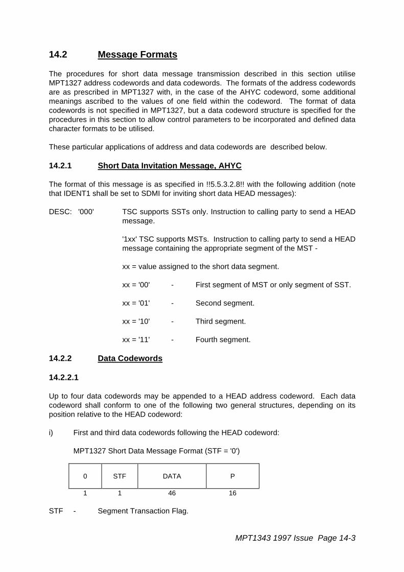
MPT1343 1997 Issue Page 14-3
14.2 Message Formats
The procedures for short data message transmission described in this section utiliseMPT1327 address codewords and data codewords. The formats of the address codewordsare as prescribed in MPT1327 with, in the case of the AHYC codeword, some additionalmeanings ascribed to the values of one field within the codeword. The format of datacodewords is not specified in MPT1327, but a data codeword structure is specified for theprocedures in this section to allow control parameters to be incorporated and defined datacharacter formats to be utilised.
These particular applications of address and data codewords are described below.
14.2.1 Short Data Invitation Message, AHYC
The format of this message is as specified in !!5.5.3.2.8!! with the following addition (notethat IDENT1 shall be set to SDMI for inviting short data HEAD messages):
DESC: '000' TSC supports SSTs only. Instruction to calling party to send a HEADmessage.
'1xx' TSC supports MSTs. Instruction to calling party to send a HEADmessage containing the appropriate segment of the MST -
xx = value assigned to the short data segment.
xx = '00' - First segment of MST or only segment of SST.
xx = '01' - Second segment.
xx = '10' - Third segment.
xx = '11' - Fourth segment.
14.2.2 Data Codewords
14.2.2.1
Up to four data codewords may be appended to a HEAD address codeword. Each datacodeword shall conform to one of the following two general structures, depending on itsposition relative to the HEAD codeword:
i) First and third data codewords following the HEAD codeword:
MPT1327 Short Data Message Format (STF = '0')
0 STF DATA P
1 1 46 16
STF - Segment Transaction Flag.
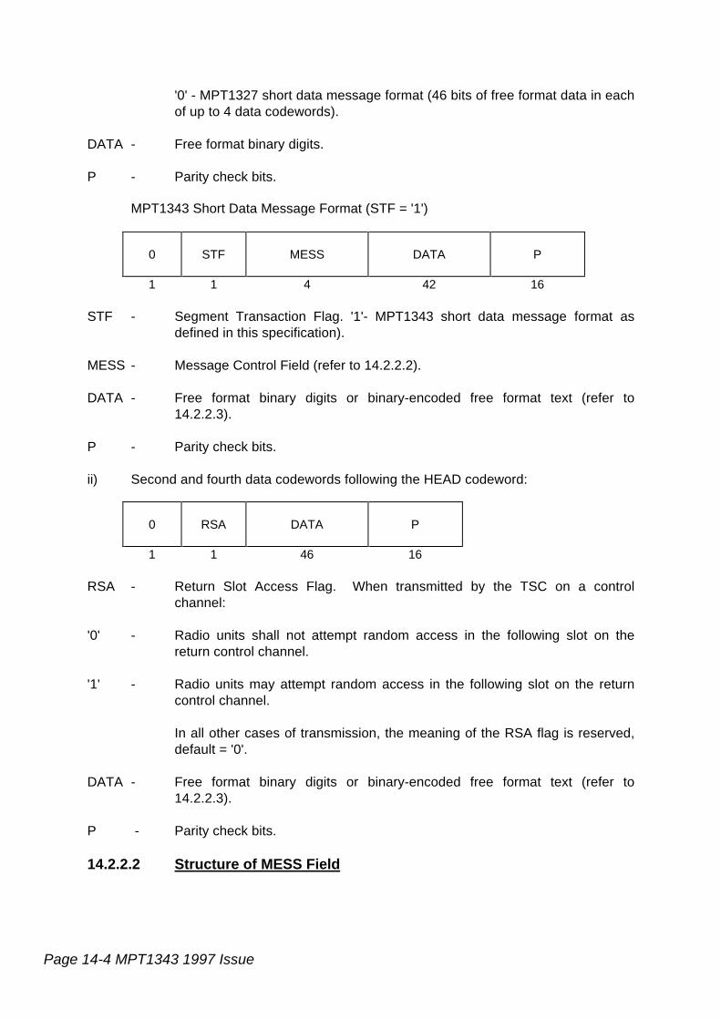
Page 14-4 MPT1343 1997 Issue
'0' - MPT1327 short data message format (46 bits of free format data in eachof up to 4 data codewords).
DATA - Free format binary digits.
P - Parity check bits.
MPT1343 Short Data Message Format (STF = '1')
0 STF MESS DATA P
1 1 4 42 16
STF - Segment Transaction Flag. '1'- MPT1343 short data message format asdefined in this specification).
MESS - Message Control Field (refer to 14.2.2.2).
DATA - Free format binary digits or binary-encoded free format text (refer to14.2.2.3).
P - Parity check bits.
ii) Second and fourth data codewords following the HEAD codeword:
0 RSA DATA P
1 1 46 16
RSA - Return Slot Access Flag. When transmitted by the TSC on a controlchannel:
'0' - Radio units shall not attempt random access in the following slot on thereturn control channel.
'1' - Radio units may attempt random access in the following slot on the returncontrol channel.
In all other cases of transmission, the meaning of the RSA flag is reserved,default = '0'.
DATA - Free format binary digits or binary-encoded free format text (refer to14.2.2.3).
P - Parity check bits.
14.2.2.2 Structure of MESS Field
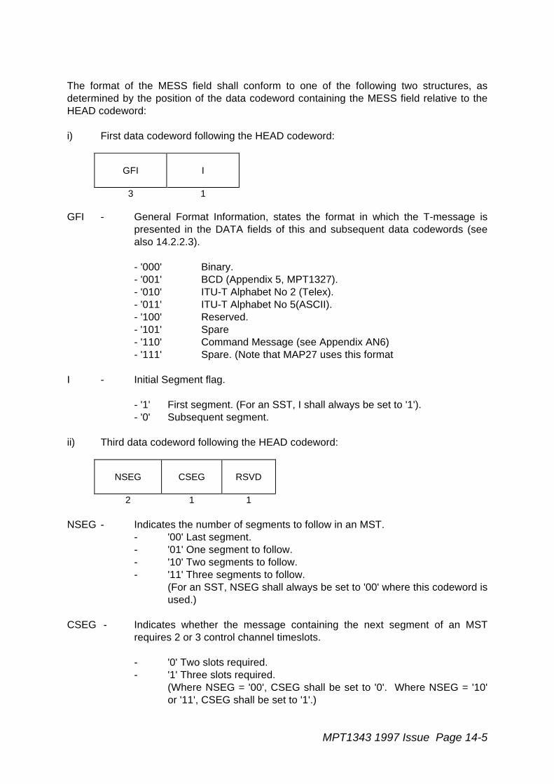
MPT1343 1997 Issue Page 14-5
The format of the MESS field shall conform to one of the following two structures, asdetermined by the position of the data codeword containing the MESS field relative to theHEAD codeword:
i) First data codeword following the HEAD codeword:
GFI I
3 1
GFI - General Format Information, states the format in which the T-message ispresented in the DATA fields of this and subsequent data codewords (seealso 14.2.2.3).
- '000' Binary.- '001' BCD (Appendix 5, MPT1327).- '010' ITU-T Alphabet No 2 (Telex).- '011' ITU-T Alphabet No 5(ASCII).- '100' Reserved.- '101' Spare- '110' Command Message (see Appendix AN6)- '111' Spare. (Note that MAP27 uses this format
I - Initial Segment flag.
- '1' First segment. (For an SST, I shall always be set to '1').- '0' Subsequent segment.
ii) Third data codeword following the HEAD codeword:
NSEG CSEG RSVD
2 1 1
NSEG - Indicates the number of segments to follow in an MST.- '00' Last segment.- '01' One segment to follow.- '10' Two segments to follow.- '11' Three segments to follow.
(For an SST, NSEG shall always be set to '00' where this codeword isused.)
CSEG - Indicates whether the message containing the next segment of an MSTrequires 2 or 3 control channel timeslots.
- '0' Two slots required.- '1' Three slots required.
(Where NSEG = '00', CSEG shall be set to '0'. Where NSEG = '10'or '11', CSEG shall be set to '1'.)
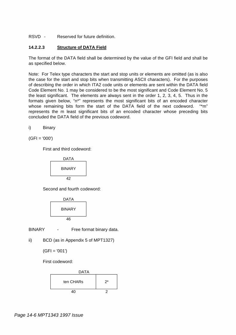
Page 14-6 MPT1343 1997 Issue
RSVD - Reserved for future definition.
14.2.2.3 Structure of DATA Field
The format of the DATA field shall be determined by the value of the GFI field and shall beas specified below.
Note: For Telex type characters the start and stop units or elements are omitted (as is alsothe case for the start and stop bits when transmitting ASCII characters). For the purposesof describing the order in which ITA2 code units or elements are sent within the DATA fieldCode Element No. 1 may be considered to be the most significant and Code Element No. 5the least significant. The elements are always sent in the order 1, 2, 3, 4, 5. Thus in theformats given below, “n*” represents the most significant bits of an encoded characterwhose remaining bits form the start of the DATA field of the next codeword. “*m”represents the m least significant bits of an encoded character whose preceding bitsconcluded the DATA field of the previous codeword.
i) Binary
(GFI = '000')
First and third codeword:
DATA
BINARY
42
Second and fourth codeword:
DATA
BINARY
46
BINARY - Free format binary data.
ii) BCD (as in Appendix 5 of MPT1327)
(GFI = '001')
First codeword:
DATA
ten CHARs 2*
40 2
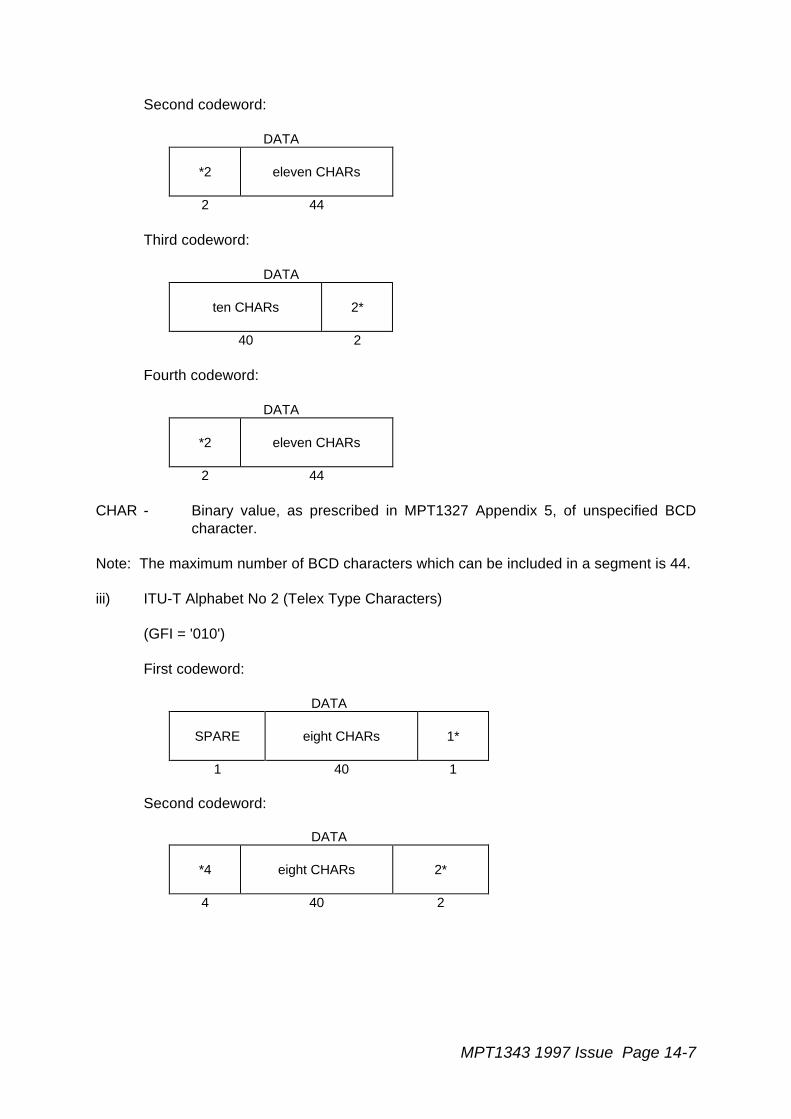
MPT1343 1997 Issue Page 14-7
Second codeword:
DATA
*2 eleven CHARs
2 44
Third codeword:
DATA
ten CHARs 2*
40 2
Fourth codeword:
DATA
*2 eleven CHARs
2 44
CHAR - Binary value, as prescribed in MPT1327 Appendix 5, of unspecified BCDcharacter.
Note: The maximum number of BCD characters which can be included in a segment is 44.
iii) ITU-T Alphabet No 2 (Telex Type Characters)
(GFI = '010')
First codeword:
DATA
SPARE eight CHARs 1*
1 40 1
Second codeword:
DATA
*4 eight CHARs 2*
4 40 2
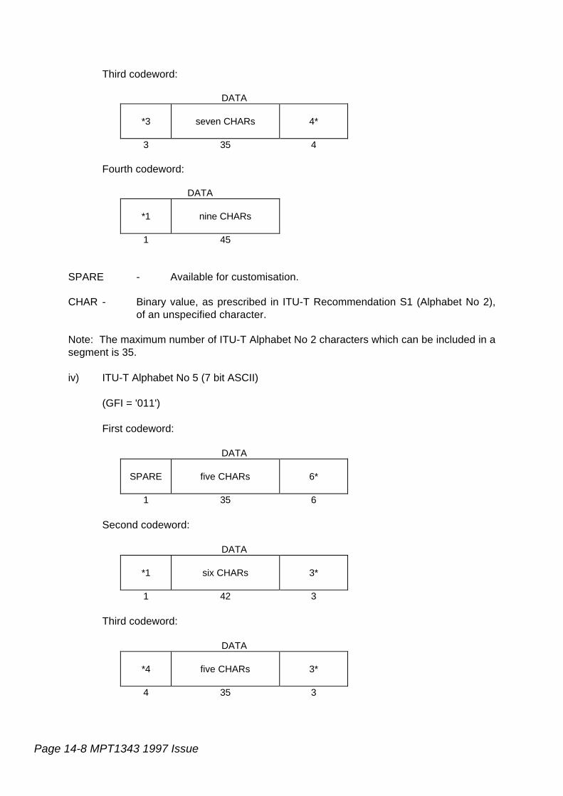
Page 14-8 MPT1343 1997 Issue
Third codeword:
DATA
*3 seven CHARs 4*
3 35 4
Fourth codeword:
DATA
*1 nine CHARs
1 45
SPARE - Available for customisation.
CHAR - Binary value, as prescribed in ITU-T Recommendation S1 (Alphabet No 2),of an unspecified character.
Note: The maximum number of ITU-T Alphabet No 2 characters which can be included in asegment is 35.
iv) ITU-T Alphabet No 5 (7 bit ASCII)
(GFI = '011')
First codeword:
DATA
SPARE five CHARs 6*
1 35 6
Second codeword:
DATA
*1 six CHARs 3*
1 42 3
Third codeword:
DATA
*4 five CHARs 3*
4 35 3

MPT1343 1997 Issue Page 14-9
Fourth codeword:
DATA
*4 six CHARs
4 42
SPARE - Available for customisation.
CHAR - Binary value, as prescribed in ITU-T Recommendation s V3, V4 (AlphabetNo 5), of an unspecified character.
Note: The maximum number of ITU-T Alphabet No 5 (7 bit ASCII) characters which can beincluded in a segment is 25.
v) Other formats
Formats for GFI values of '100' is reserved for future definition and GFI='101 is spare. GFI= '110' indicates a control message directed to the recipient radio unit (see Appendix AN6),GFI = '111' is spare for customisation. (Note that MAP27 uses the GFI='111' format)
14.3 The Use of Control Fields for STF = '1'
A calling radio unit divides its T-message into a maximum of four segments, where allsegments except the last utilise exactly four data codewords. The last segment may utiliseup to four data codewords as required to accommodate the T-message. The segments ofa Multiple Segment Transaction are logically linked by the 'NSEG', 'CSEG' and 'I' fields.
A HEAD message containing the first segment shall have the I bit set to '1', and thosecontaining subsequent segments shall have I set to '0'.
The NSEG field represents a decrementing counter which shall indicate the number ofsegments to follow to complete the transaction such that the value of NSEG is '00' for thelast segment of an MST. If the last segment uses less than three data codewords, then theNSEG field will not be transmitted and the recipient shall behave as though its value hadbeen '00'.
The CSEG field informs the TSC of the number of slots required for data codewordscontaining the next segment. The value shall always be '1' when transmitted with leadingsegments (NSEG = '10' or '11') and may be either '1' or '0' when transmitted with thepenultimate segment (NSEG = '01'). With the final segment CSEG defaults to '0' and theTSC will ignore the value.
HEAD messages transmitted by the TSC to a called radio unit or group shall contain thesame values of I, NSEG and CSEG as those of messages containing the correspondingsegments received by the TSC from a calling radio unit. The called radio unit may performa check to ensure that the values of these fields are logically consistent.
Page 14-10 MPT1343 1997 Issue
An example, illustrating the use of the Control fields, is given in 14.5.
The called radio unit uses the values of STF and NSEG in the HEAD messages todetermine which value to use in the individual incoming short data timer. See section14.4.2.1.
14.4 Procedures for Radio Units
Radio units which implement the option to transmit and receive short data messages (eitherSSTs or MSTs) shall comply with the requirements of !!14!!. In addition radio units shallmeet the requirements of this specification which are given below.
14.4.1 Radio Unit Actions when Sending Short Data Messages
14.4.1.1 Composition of HEAD Messages
A radio unit complying with the procedures of this section shall set STF = '1' in allappropriate data codewords transmitted.
For an SST, the calling radio unit shall transmit its T-message by sending one segment.For an MST, all segments except possibly the last shall utilise exactly four data codewords.
A HEAD message containing a segment shall only be transmitted following an invitationfrom the TSC. For every message transmitted to, or received from, the TSC the radio unitshall operate the appropriate timer (see !!14.2.6!!). After sending the last segment theradio unit shall wait for the appropriate acknowledgement (see !!14.2.4!!).
The control information for the first segment (of an SST or MST) shall be composed asfollows:
i) The GFI bits in the MESS field in the data codeword directly following the HEADaddress codeword shall be set as appropriate to indicate the format of the T-message.
ii) The I bit of the MESS field in the DATA codeword directly following the HEADaddress codeword shall be set to '1'.
In the case of a HEAD address codeword with three or more appended data codewords,the control fields in the third data codeword shall be set as follows:
i) NSEG shall be set to indicate the number of segments to follow (NSEG shall be setto '00' for an SST).
ii) CSEG shall be set to indicate the number of timeslots required for the next MSTsegment (CSEG shall be set to '0' when NSEG has the value '00').
The control information for subsequent segments of an MST shall be composed asprescribed above except that the I bit of the MESS field shall be set to '0'.
MPT1343 1997 Issue Page 14-11
14.4.1.2 Message Transmission Procedures
When a radio unit is ready to send a short data message it shall send RQC (with the valueof SLOTS set either to '10' for an SST requiring a HEAD message with one or two datacodewords, or to '11' for either an SST requiring a HEAD message with more than two datacodewords or an MST). It shall then await responses as specified in !!14.2.1!! to !!14.2.3!!.
Upon receipt of a Mode 1 AHYC (DESC = '000'), with IDENT1 set to SDMI andPFIX/IDENT2 matching its individual address, a radio unit shall send a HEAD message withNSEG = '00', CSEG = '0' and I = '1' as a response. The same HEAD message shall beretransmitted by the radio unit if a further identical AHYC is received. Note that a radio unitwishing to transmit a T-message with more than one segment which receives AHYC (DESC= '000') shall respond with a HEAD message containing the first segment. After thecompletion of this transaction, it may then attempt to initiate transmission of the remainderof the T-message by sending one or more subsequent RQC random access requestmessages.
Upon receipt of a Mode 1 AHYC (DESC = '100'), with IDENT1 set to SDMI andPFIX/IDENT2 matching its individual address, a radio unit shall send a HEAD messagecontaining either the complete T-message of an SST, or the first segment of the T-message of an MST, as a response. The same HEAD message shall be retransmitted bythe radio unit if a further identical AHYC is received.
Upon receipt of a Mode 1 AHYC, with IDENT1 set to SDMI and PFIX/IDENT2 matching itsindividual address, and where DESC has incremented by one binary count from that in theprevious AHYC message addressed to it, a radio unit shall send a HEAD messagecontaining the next segment of the MST (note: DESC values of '101', '110' and '111'correspond to 2nd, 3rd and 4th MST segments respectively). The same HEAD messageshall be retransmitted by the radio unit if a further identical AHYC is received. If a Mode 1AHYC message is received whose value of DESC is not consistent with the correctsegment order for the T message then the radio unit shall transmit ACKX (QUAL = '0').
14.4.2 Procedures for All Radio Units on a Control Channel
The procedures in this section shall be obeyed by all radio units that are equipped toaccept short data messages (either SSTs or MSTs). The ability to accept short datamessages is a standard option.
If flag STF in a received HEAD message is set to '0' (see 14.2.2) then the radio unitbehaviour shall be in accordance with !!14.3!! but any additional procedures shall besystem dependent.
If flag STF in a received HEAD message is set to '1' then the procedures below shall apply.
14.4.2.1 Receiving Individually Addressed Short Data
Alternative Procedures for Radio Units receiving individually addressed MSTs and SSTsare specified. The first, in Section 14.4.2.1.1, conforms to the requirements specified inthis document as revised and printed in September 1991. The second, in Section14.4.2.1.2, is a revised procedure which offers a receiving radio unit the opportunity toaccept MSTs and SSTs at an increased rate, limited by the data signalling capacity of the

Page 14-12 MPT1343 1997 Issue
control channel more than the expiry of timers in the radio unit. All radio units are required,when implementing this second option, to at least implement the first procedure to ensurecompatibility with existing networks. The second procedure may be implemented and usedwhen allowed by network personalisation.
Radio Units that are able to function using either procedure shall implement a NetworkPersonalisation MST Flag which when set to '0' shall cause the unit to carry out theprocedure specified in Section 14.4.2.1.1 and when set to '1' shall cause the unit to carryout the procedure specified in Section 14.4.2.1.2.
14.4.2.1.1 Original Procedure
14.4.2.1.1.1 Called Unit Response to AHY Message
If a radio unit on a control channel receives an AHY message with:- POINT set to '0',- PFIX/IDENT1 as its individual address, and- IDENT2 set to SDMI,
then it shall respond by sending a suitable acknowledgement; see !!9.2.2.2B!!.
If the radio unit's response is ACK (QUAL = 0) then the unit shall start timer TA and shallwait for further signalling; see also sections 14.4.2.1.1.2, 14.4.2.1.1.3 14.4.2.1.3 and14.4.2.1.4.
14.4.2.1.1.2 Receiving Individually Addressed HEAD Message
If a radio unit on a control channel receives a HEAD message with PFIX1/IDENT1 in theHEAD address codeword matching its individual address then it shall behave as describedbelow.
a. The radio unit shall accept, reject or solicit a repeat of that message by respondingwith a suitable acknowledgement (respectively ACK (QUAL = 0), ACKX or ACKV(QUAL = 1), or ACKB (QUAL = 1)). See !!14.3.1.1!! and also points b. to f. below.
b. If the radio unit is in a state of waiting for further HEAD messages (see section14.4.2.1.1.3) then it shall reject the received segment by responding with ACKX(QUAL = 1) if PFIX2/IDENT2 in the HEAD address codeword does not matchPFIX2/IDENT2 from previously received HEAD messages for that transaction towhich it responded with ACK (QUAL = 0) or ACKB (QUAL = 1).
c. The radio unit shall note the value of the I flag in the MESS field of the first datacodeword.
If the radio unit:
- is not in a state of waiting for further HEAD messages (see section14.4.2.1.1.3), or
- is awaiting retransmission of a HEAD message with I set to '1' which itsolicited using ACKB (QUAL = 1), or

MPT1343 1997 Issue Page 14-13
- is in a state of waiting for further HEAD messages, having received a HEADmessage with I set to '1' and NSEG set to '00',
then it shall reject the received HEAD message if the I flag is set to '0' byresponding ACKX (QUAL = 1).
If the radio unit has sent ACK (QUAL = 0) or ACKB (QUAL = 1) in response to apreviously received HEAD message for that transaction containing I set to '0', then itshall reject the received HEAD message if the I flag is set to '1' by respondingACKX (QUAL = 1).
d. The radio unit shall note the value of LEN in the HEAD address codeword. For LEN= '00' or '01' the radio unit shall not expect to receive NSEG in the appended datacodewords but shall behave as though its value had been '00' (see !!15.6.2!!).
e. The radio unit shall record the value of the NSEG control field in the third datacodeword if the HEAD message contains three or four data codewords.
If the radio unit is in a state of waiting for further HEAD messages (see section14.4.2.1.1.3) then:
- the HEAD message shall be deemed to be a repeat transmission of the lastreceived HEAD message if both have identical values of NSEG;
- the segment contained in the HEAD message shall be deemed to be the firsttransmission thereof to be received by the radio unit if the value of NSEG hasbeen decremented by one binary count from that of the last received HEADmessage.
- If a head message is received whose value of NSEG is not consistent with thecorrect segment order for the T message then the radio unit shall transmitACKX(QUAL=1).
The radio unit shall reject any received HEAD message by sending ACKX (QUAL = 1)where the value of NSEG:
- has been incremented since the last received HEAD message, or- has been decremented by more than one binary count since the last received
HEAD message, or- has been decremented and the previous segment has not been decoded
successfully.
If the radio unit is not in a state of waiting for further HEAD messages then any value ofNSEG is valid.
f. If the HEAD message contains one or more corrupted data codewords, the radiounit may extract uncorrupted data codewords from this and subsequentretransmissions thereof, until it is able to assemble a complete and uncorruptedsegment. If a retransmission of the HEAD message is required, then the radio unitshall respond with ACKB (QUAL = 1).
When the segment has been assembled, the radio unit shall respond with eitherACK (QUAL = 0) or ACKX (QUAL = 1) as appropriate.

Page 14-14 MPT1343 1997 Issue
g. If the radio unit responds to the HEAD message with ACK (QUAL = 0) or ACKB(QUAL = 1), then the unit shall start timer TM (if NSEG¹0) or TGI (if NSEG=0) andshall wait for further signalling; see also section 14.4.2.1.1.3.
For other responses, the radio unit shall leave its individual incoming short datatimer in its existing state (either running, or not set, as appropriate).
The radio unit shall offer the complete T-message to the user when a HEADmessage with NSEG = '00' has first been successfully decoded (or its associatedsegment has been assembled as in point f. above). The T-message shall beformatted in accordance with the GFI bits in the MESS field. The radio unit shallthen continue to wait as defined in section 14.4.2.1.1.3.
14.4.2.1.1.3 Individual Time-out TGI/TA
Radio units shall operate an individual incoming short data timer which shall be set to eitherof two different values as described below.
The timer shall be set to a value TA and started or restarted when the radio unit respondswith ACK (QUAL = 0) to an AHY message with IDENT2=SDMI. The timer shall be set to avalue TGI and started or restarted when the radio unit responds with ACK (QUAL = 0) orACKB (QUAL = 1) to a HEAD message.
A radio unit is in a state of waiting for further signalling for an incoming individuallyaddressed short data transaction if its individual incoming short data timer is running. Aradio unit is in a state of waiting for further HEAD messages if this timer is running and theradio unit has received and responded to an earlier HEAD message with ACK (QUAL = 0)or ACKB (QUAL = 1) during that transaction.
A radio unit waiting for further signalling for an incoming individually addressed short datatransaction (SST or MST) shall assume that no further signalling will be received for thattransaction if its individual incoming short data timer expires.
Thereupon, if the T-message has not been fully decoded, the short data transaction shallbe deemed to have failed and the radio unit may generate an appropriate indication to theuser. The radio unit may offer an incomplete T-message to the user only if a suitablewarning of incompleteness is included with the data presented to the user.
Note: if the T-message has been fully decoded, then it already should have been offered tothe user at that time (see 14.4.2.1.1.2).
After expiry of the individual incoming short data timer, the radio unit shall discard therecorded values of the control fields and shall assume that future HEAD and AHY (IDENT2= SDMI) messages are for another transaction.
The value of TGI is network dependent and shall be programmable as part of a radio unit'spersonality with a range of 1 to 15 seconds in 1 second steps. The recommended value forTGI is 5 seconds. For the permissible value for TA, refer to section 6.

MPT1343 1997 Issue Page 14-15
14.4.2.1.2 Revised Protocol
The procedures specified in this section differs from the procedures defined in 14.4.2.1 inthat:
a) The TSC retains in its subscriber database, or by other means, a flag to indicatethat the individually addressed radio unit complies with this revised protocol i.e.operates timer TM (see below) and is able to clear timer TGI on receipt of eitherAHY, IDENT2=SDMI or AHY, D=0 etc.
b) Once the Radio Unit has responded to an AHY, IDENT2 = SDMI with ACK,QUAL = '0' and has then received an applicable HEAD message, any new AHY,IDENT2 = SDMI indicates the commencement of a new MST. If the new AHY isreceived before the completion of the current MST in progress the unit may respondto the new AHY with an appropriate response rejecting it or may abandon the call inprogress and discard the message so far received. The chosen course is forced bynetwork personalisation flags.
c) Once the Radio Unit has responded to an AHY, IDENT2 = SDMI with ACK,QUAL = '0' and has then received an applicable HEAD message, a new AHY,IDENT2 = Individual Address indicates the commencement of a speech call. If theAHY is received before the completion of the current MST in progress the unit mayrespond to the AHY, IDENT2 = Individual Address with an appropriate responserejecting it or may abandon the call in progress and discard the message so farreceived. The choice of action may be made dependent on the state of the 'E' flagin the new AHY message. The chosen course is forced by network personalisationflags.
d: For individually addressed MSTs, once all segments of an MST have been receivedand the radio unit has sent a final acknowledgement, the receipt of an AHY, withany value of IDENT2, from the TSC indicates that the acknowledgement has beenreceived by the TSC, which is commencing a new transaction with the unit. TheRadio Unit therefore terminates all timers associated with the previous message andresponds to the TSC with an acknowledgement to indicate that it is accepting theahoy as the commencement of a new transaction.
e) A new timer, TM, has been introduced to avoid the use of TA.
f) The radio unit may accept a new MST for each address which it contains whilst inthe process of assembling a message in progress. i.e. the unit's individual addressand each of its group addresses. The radio unit may limit the number of groupaddresses for which it accepts MSTs simultaneously to any number. Note that theunit risks the chance of missing a segment if the TSC sends an applicable groupHEAD message in the slot immediately after an applicable individual HEADmessage because the radio unit will be acknowledging the individually addressedmessage.
14.4.2.1.2.1 Called Unit Response to AHY Message
If a radio unit on a control channel receives an AHY message with:

Page 14-16 MPT1343 1997 Issue
- POINT set to '0',- PFIX/IDENT1 as its individual address,- D='1', and- IDENT2 set to SDMI,
then it shall respond by sending a suitable acknowledgement; see !!9.2.2.2B!!.
The unit shall start timer TM and shall wait for further signalling; see also sections14.4.2.1.2.2, 14.4.2.1.2.3, 14.4.2.1.3 and 14.4.2.1.4.
If the radio unit is waiting in timer TM for further signalling in an MST and receives an AHY,POINT = '0' it shall respond with either:
- ACKV (QUAL = 1) to indicate that it is busy or
- with an acknowledgement appropriate to the AHY and abandon any MSTwhich is in progress. See 14.2.1.2 b) above.
14.4.2.1.2.2 Receiving Individually Addressed HEAD Message
If a radio unit on a control channel receives a HEAD message with PFIX1/IDENT1 in theHEAD address codeword matching its individual address then it shall behave as describedbelow.
a. The radio unit shall accept, reject or solicit a repeat of that message by respondingwith a suitable acknowledgement (respectively ACK (QUAL = 0), ACKX or ACKV(QUAL = 1), or ACKB (QUAL = 1)). See !!14.3.1.1!! and also points b. to f. below.
b. If the radio unit is in a state of waiting for further HEAD messages (see section14.4.2.1.2.3) then it shall reject the received segment by responding with ACKX(QUAL = 1) if PFIX2/IDENT2 in the HEAD address codeword does not matchPFIX2/IDENT2 from previously received HEAD messages for that transaction towhich it responded with ACK (QUAL = 0) or ACKB (QUAL = 1).
c. The radio unit shall note the value of the I flag in the MESS field of the first datacodeword.
If the radio unit:
- is not in a state of waiting for further HEAD messages (see section14.4.2.1.2.3), or
- is awaiting retransmission of a HEAD message with I set to '1' which itsolicited using ACKB (QUAL = 1), or
- is in a state of waiting for further HEAD messages, having received a HEADmessage with I set to '1' and NSEG set to '00',
then it shall reject the received HEAD message if the I flag is set to '0' byresponding ACKX (QUAL = 1).
If the radio unit has sent ACK (QUAL = 0) or ACKB (QUAL = 1) in response to a previouslyreceived HEAD message for that transaction containing I set to '0', then it shall reject thereceived HEAD message if the I flag is set to '1' by responding ACKX (QUAL = 1).

MPT1343 1997 Issue Page 14-17
d. The radio unit shall note the value of LEN in the HEAD address codeword. ForLEN = '00' or '01' the radio unit shall not expect to receive NSEG in the appendeddata codewords but shall behave as though its value had been '00' (see !!15.6.2!!).
e. The radio unit shall record the value of the NSEG control field in the third datacodeword if the HEAD message contains three or four data codewords.
If the radio unit is in a state of waiting for further HEAD messages (see section14.4.2.1.2.3) then:
- the HEAD message shall be deemed to be a repeat transmission of the lastreceived HEAD message if both have identical values of NSEG;
- the segment contained in the HEAD message shall be deemed to be the firsttransmission thereof to be received by the radio unit if the value of NSEG hasbeen decremented by one binary count from that of the last received HEADmessage.
- If a head message is received whose value of NSEG is not consistent with thecorrect segment order for the T message then the radio unit shall transmitACKX(QUAL=1).
The radio unit shall reject any received HEAD message by sending ACKX (QUAL = 1)where the value of NSEG:
- has been incremented since the last received HEAD message, or- has been decremented by more than one binary count since the last received
HEAD message, or- has been decremented and the previous segment has not been decoded
successfully.
If the radio unit is not in a state of waiting for further HEAD messages then any value ofNSEG is valid.
f. If the HEAD message contains one or more corrupted data codewords, the radiounit may extract uncorrupted data codewords from this and subsequentretransmissions thereof, until it is able to assemble a complete and uncorruptedsegment. If a retransmission of the HEAD message is required, then the radio unitshall respond with ACKB (QUAL = 1).
When the segment has been assembled, the radio unit shall respond with eitherACK (QUAL = 0) or ACKX (QUAL = 1) as appropriate.
g. If the radio unit responds to the HEAD message with ACK (QUAL = 0) or ACKB(QUAL = 1), then the unit shall start timer TM and shall wait for further signallingunless, when responding ACK (QUAL = 0), the NSEG field is set to '00' or there isno third data codeword in the segment then the unit shall start timer TGI; see alsosection 14.4.2.1.2.3.
For other responses, the radio unit shall leave its individual incoming short datatimer in its existing state (either running, or not set, as appropriate).
Page 14-18 MPT1343 1997 Issue
The radio unit shall offer the complete T-message to the user when a HEADmessage with NSEG = '00' has first been successfully decoded (or its associatedsegment has been assembled as in point f. above). The T-message shall beformatted in accordance with the GFI bits in the MESS field. The radio unit shallthen continue to wait as defined in section 14.4.2.1.2.3.
h. Once a radio unit has received a HEAD message with the NSEG field set to anyvalue other than '00' it may reject any AHY message containing IDENT2 = SDMIwith ACKX (QUAL = 1) and continue to wait for the next HEAD message orabandon the transaction in progress, abandon the message so far received andcommence a new transaction dependent on the state of the 'E' flag on the AHYmessage. (See 14.4.2.1.2, b)).
14.4.2.1.2.3 Individual Time-out TGI/TM
If the Network Personalisation Flag is set to '1' (See 14.4.2.1.) radio units shall operate anindividual incoming short data timer which shall be set to either of two different values asdescribed below.
The timer shall be set to a value TM and started or restarted when the radio unit respondswith ACK (QUAL = 0) to an AHY message with IDENT2=SDMI. The timer shall also be setto a value TM and started or restarted when the radio unit responds with ACK (QUAL = 0)to a HEAD message which contains a value other than '00' in the NSEG field or ACKB(QUAL = 1) to any HEAD message. The timer shall be set to a value TGI and started orrestarted when the radio unit responds with ACK (QUAL = 0) to a HEAD message whichcontains a value of '00' in the NSEG field or where the segment does not contain a thirddata codeword. (i.e. if the message is an SST or for the last segment of an MST.)
A radio unit is in a state of waiting for further signalling for an incoming individuallyaddressed short data transaction if its individual incoming short data timer is running. Aradio unit is in a state of waiting for further HEAD messages if this timer is running and theradio unit has received and responded to an earlier HEAD message with ACK (QUAL = 0)or ACKB (QUAL = 1) during that transaction.
A radio unit waiting for further signalling for an incoming individually addressed short datatransaction (SST or MST) shall assume that no further signalling will be received for thattransaction if its individual incoming short data timer expires.
Thereupon, if the T-message has not been fully decoded, the short data transaction shallbe deemed to have failed and the radio unit may generate an appropriate indication to theuser. The radio unit may offer an incomplete T-message to the user only if a suitablewarning of incompleteness is included with the data presented to the user.
Note: if the T-message has been fully decoded, then it already should have been offered tothe user at that time (see 14.4.2.1.2.2).
After expiry of the individual incoming short data timer, the radio unit shall discard therecorded values of the control fields and shall assume that future HEAD and AHY(IDENT2 = SDMI) messages are for another transaction.
MPT1343 1997 Issue Page 14-19
The value of TM is network dependent and shall be programmable as part of a radio unit'spersonality with a range of 1 to 60 seconds in 1 second steps. The recommended value forTM is 15 seconds. See Section 6.
The value of TGI is network dependent and shall be programmable as part of a radio unit'spersonality with a range of 1 to 60 seconds in 1 second steps. The recommended value forTGI is 5 seconds. See Section 6.
If a final or single segment is sent which contains only two data codewords following theHEAD codeword then NSEG is not transmitted. In this case the radio unit shall behave asif NSEG is set to '00'.
When a radio unit has responded with ACK (QUAL=0) to a HEAD message containingNSEG='00' and it receives AHY, with IDENT1 set to the unit's individual address it shallcease to wait for further signalling for the short data message it has just received. IfIDENT2=SDMI the radio unit shall start the individual incoming short data timer with a valueof TM for a new message. (During the time TGI after the final HEAD message an AHYmessage sent by the TSC indicates that it has received the ACK as well as announcing anew message).
14.4.2.1.3 Receiving AHYX Message
If, whilst waiting for further signalling for an incoming individually addressed short datatransaction, a radio unit receives an AHYX message with:
- PFIX/IDENT1 as its individual address, and- IDENT2 set to SDMI
then it shall respond with ACK (QUAL = 1) as defined in !!9.2.2.4!! and shall cease to waitfor further signalling. It shall terminate the individual incoming short data timer (TGI, TMand TA), discard any segments decoded in connection with that transaction, discard therecorded values of the control fields and assume that future AHY (IDENT2 = SDMI) andHEAD messages are for another transaction.
This use of AHYX is in addition to the MPT1327 prescribed functions.
14.4.2.1.4 Ignoring Group Call GTC Messages
A radio unit waiting for further signalling for an incoming individually addressed short datatransaction shall ignore any received GTC message unless the unit is individuallyaddressed by that GTC message (either by PFIX/IDENT1 or by PFIX/IDENT2) or IDENT1 isset to ALLI.
This requirement is in addition to the procedure in !!9.2.2.5!!.
14.4.2.1.5 Maintaining Timers
A radio unit waiting for further signalling for an incoming short data transaction shallmaintain any relevant timers, including its individual incoming short data timer, asprescribed in section 9.4.2, when leaving the control channel on which it is currently active.
Page 14-20 MPT1343 1997 Issue
14.4.2.2 Receiving Short Data Addressed to a Group
The procedures for receiving group call short data messages remains unchanged in thisrevision of the specification.
14.4.2.2.1 Receiving HEAD Message Addressed to a Group
If a radio unit on a control channel receives a HEAD message with PFIX2/IDENT2 notmatching its individual address and:
- PFIX/IDENT1 matching one of its group addresses for that system, or- IDENT1 set to the system-wide all-call ident ALLI
then it may follow the procedures outlined in this section but shall transmit no response.For the purposes of this section, the term "group-addressed HEAD message" shall meanany HEAD message so addressed.
If a radio unit receives a group-addressed HEAD message containing the I flag set to '1'and NSEG is set to '00' or not included, then this message constitutes an SST. If a radiounit receives a group-addressed HEAD message containing NSEG set to a value otherthan '00' or I is set to '0' then this message constitutes part of an MST.
If a radio unit receives a group-addressed HEAD message whilst in the state of waiting forfurther signalling for a short data transaction addressed to that group, it shall ignore thatmessage if the calling address PFIX2/IDENT2 does not match PFIX2/IDENT2 from anypreviously accepted HEAD message for that transaction.
If a received group-addressed HEAD message contains one or more corrupted datacodewords, the radio unit may extract uncorrupted data codewords from this andsubsequent retransmissions thereof, until it is able to assemble a complete anduncorrupted segment. The radio unit shall use the fields PFIX1/IDENT1, PFIX2/IDENT2,LEN, I and NSEG to identify repeat transmissions and to determine whether all segmentsof a T-message have been decoded as follows:
a. If a received HEAD message contains the I flag set to '0' and the radio unit is not inthe state of waiting for further signalling for a short data transaction addressed tothis group, then the unit shall deem that insufficient segments will be received forthat transaction to assemble a complete T-message.
b. The radio unit shall note the value of LEN in the HEAD address codeword of areceived group-addressed HEAD message. For LEN = '00' or '01' the radio unitshall not expect to receive NSEG in the appended data codewords but shall behaveas though its value had been '00' (see !!5.6.2!!).
c. The radio unit shall record the value of the NSEG control field in the third datacodeword of a received group-addressed HEAD message if it contains three or fourdata codewords.
If the radio unit is in a state of waiting for further signalling for a short data transaction forthat group (see section 14.4.2.2.2) then:

MPT1343 1997 Issue Page 14-21
- the HEAD message shall be deemed to be a repeat transmission of the lastreceived HEAD message for that group if both have identical values of NSEG.
- the segment contained in the HEAD message shall be deemed to be the firsttransmission thereof to be received by the radio unit if the value of NSEG hasbeen decremented from that of the last received HEAD message for thatgroup.
- If a head message is received whose value of NSEG is not consistent with thecorrect segment order for the T message then the radio unit shall transmitACKX(QUAL=1).
The radio unit shall deem that insufficient segments will be received to assemble acomplete T-message where the value of NSEG:
- has been decremented by more than one binary count since the last receivedHEAD message, or
- has been decremented and the previous segment has not been decodedsuccessfully.
After accepting a group-addressed HEAD message the radio unit shall then wait for furtherHEAD messages for that transaction (see 14.4.2.2.2).
When a HEAD message with NSEG set to '00' has first been successfully decoded (or itsassociated segment has been assembled) then, if the T-message is complete, the unit shalloffer the T-message to the user. Otherwise, if the T-message is incomplete, the radio unitmay offer the received data to the user only if a suitable warning of incompleteness isincluded with the data presented to the user. The T-message or segments thereof shall beformatted in accordance with the GFI bits in the MESS field. The radio unit shall thencontinue to wait, as defined in section 14.4.2.2.2.
14.4.2.2.2 Group Time-out TGG
A called radio unit waiting for further signalling for a short data transaction addressed to agroup shall assume that no further signalling will be received for that transaction (SST orMST) if a time TGG has elapsed since the last HEAD message it received for thattransaction. The radio unit shall discard the recorded values of the control fields and shallassume that any future HEAD messages are for another transaction.
Thereupon, if the T-message has not been fully decoded, the short data transaction shallbe deemed to have failed. The radio unit may offer an incomplete T-message to the useronly if a suitable warning of incompleteness is included with the data presented to the user.
The value of TGG is network dependent and shall be programmable as part of a radiounit's personality with a range of 1 to 30 seconds in 1 second steps. The recommendedvalue for TGG is 10 seconds.
14.4.2.2.3 Maintaining Timers
A radio unit waiting for further signalling for an incoming short data transaction shallmaintain any relevant timers, including its group incoming short data timer, as prescribed insection 9.4.2, when leaving the control channel on which it is currently active.

Page 14-22 MPT1343 1997 Issue
14.5 An Example of The Procedure for Extended DataMessages
In order to illustrate the use of the procedure in section 14, a typical message interchangeis shown in Figure 14.1. The example shows a successful Multiple Segment Transactionlinking three segments. An SST would be similar to the transmission of the first segment ofthe MST, but with the appropriate field values changed in the HEAD message. Thisexample is illustrative only and does not form part of the specification.
In the example, an availability check is carried out on the called radio unit and somesegment repeats are shown.
Figure 14.1 - Example of Successful MST Transaction
REQUESTING
PARTY
| 1 |→
←| 4 || 5 |→
←| 6 || 7 |→
←| 8 || 9 |→
←| 10 || 11 |→
←| 21 |
TSC
| 2 |→←| 3 |
| 12 |→←| 13 |
| 14 |→←| 15 |
| 16 || 17 |→←| 18 |
| 19 |→←| 20 |
CALLED
PARTY
Descriptions of message interchanges
|1|: An RQC message requests a short data transaction (Assuming extendedaddressing is not required). The value of SLOTS in the RQC is '11', indicating thatthree slots are required for the HEAD message containing the first segment of theMST.

MPT1343 1997 Issue Page 14-23
|2|: An AHY (POINT=0) message checks the availability of the called radio unit(optional).
|3|: An ACK (QUAL=0) message indicates general acknowledgement of the AHY.
|4|: Any AHYC message is sent to the requesting radio unit with DESC set to '100'. Thefirst bit of DESC indicates that MSTs are supported. The second and third bitsindicate that the first segment is required. SLOTS is set to '11' to indicate that threeslots have been reserved for the HEAD message containing the first segment of theT-message.
|5|: A HEAD message containing the first segment of the MST is sent. The GFI fieldindicates the format of the T-message data. NSEG = '10' indicates that two moresegments are yet to be sent. CSEG = '1' indicates that three slots are required forthe HEAD message containing the next segment.
|6|: An AHYC message with DESC '101' solicits a HEAD message containing thesecond segment of the MST. SLOTS is set to '11' to indicate that three slots havebeen reserved for the HEAD message.
|7|: A HEAD message containing the second segment of the ST is sent. NSEG = '01'indicates that one more data segment is to be sent. CSEG = '0' indicates that twoslots are required for the HEAD message containing the next segment.
|8|: An AHYC message with DESC = '101' solicits a repeat of the second segment ofthe MST. SLOTS is set as in |6|.
|9|: A HEAD message containing the second segment is retransmitted as in |7|.
|10|: An AHYC message with DESC = '110' solicits a HEAD message containing the thirdsegment of the MST. SLOTS is set to '10' to indicate that two slots have beenreserved for the HEAD message.
|11|: A HEAD message containing the third segment of the MST is sent. Since themessage only contains two data codewords, NSEG (which is transmitted in the thirdcodeword when present) is not sent. The TSC behaves as though its value hadbeen '00'.
|12|: The TSC sends a HEAD message containing the first segment of the MST to calledparty. LEN is set to '11' to indicate that four data codewords are appended to theHEAD codeword and NSEG in the third appended data codeword is set to '10' toindicate that two segments of the MST are to follow.
|13|: An ACKB (QUAL=1) message indicates that the called party required the firstsegment to be transmitted.
|14|: The TSC sends a HEAD message containing a repeat of the first segment as in|12|.
|15|: An ACK (QUAL=0) message indicates successful receipt of the HEAD message bythe called radio unit.

Page 14-24 MPT1343 1997 Issue
|16|: The TSC sends a HEAD message containing the second segment of the MST. LENis set to '11' to indicate that four data codewords are appended to the HEADcodeword and NSEG in the third appended data codeword is set to '01' to indicatethat one segment of the MST is to follow.
|17|: No acknowledgement is received by the TSC in the subsequent slot so a HEADmessage containing a repeat of the second segment is transmitted as in |16|.
|18|: An ACK (QUAL=0) message indicates successful receipt of the HEAD message bythe called radio unit.
|19|: The TSC sends a HEAD message containing the final segment of the MST. LEN isset to '01' to indicate that two data codewords are appended to the HEADcodeword. Since the message only contains two data codewords NSEG (which istransmitted in the third codeword when present) is not sent. The radio unit behavesas though its value had been '00'.
|20|: An ACK (QUAL=0) message indicates successful receipt of the HEAD message bythe called radio unit.
|21|: An ACK (QUAL=0) message is sent by the TSC to the calling party to indicate thatthe transaction has been successfully completed. This acknowledgement may berepeated for reliability.
MPT1343 TSMG 1997 Issue Page A-1
APPENDIX A: ERROR RATE PERFORMANCE
A.1 Definition
The receiver FSK demodulator error rate performance is measured in terms of the successrate of Ahoy codewords (see MPT 1327 section 5.5.3.2 for the definition of Ahoycodewords).
A.2 Method of Measurement
The unit under test shall be programmed to respond to the PFIX/IDENT given in Figure A-2.It shall also be programmed to scan a channel which satisfies the value of CHAN4specified in Figure A-2 (i.e. the least significant 4 bits of the CHAN field shall matchCHAN4).
A block diagram of the test set up is shown in Figure A-1. Serial data generator 'A'produces a test data stream of the form shown in Figure A-2. This data stream is fed toaudio band FFSK modulator 'B', which modulates the data stream according to MPT 1323section 6.1.1. The modulated audio signal is fed to RF signal generator 'C'. RF signalgenerator 'C' is set up to produce a signal of carrier frequency equal to the nominalfrequency of the receiver, and modulated to a peak frequency deviation of ±1.5kHz. Theresulting RF signal is fed through attenuator 'D' to resistive combiner 'F' where it iscombined with simulated ignition pulses from generator 'E'. Ignition pulse simulator 'E'produces a stream of pulses of 10 volt peak and duration <3ns at a 18Hz rate. Thecombined signal is fed through circulator 'G' to the input terminals of the unit under test 'H'.The transmissions from unit under test 'H' pass through the circulator 'G' to RF load 'I'which feeds power detector 'J'. Power detector 'J' is designed to ignore the pulses fromignition simulator 'E'. If power above the threshold is detected by 'J', either counter 'L' orcounter 'M' is incremented, depending upon whether serial data generator 'A' indicates thata transmission is expected. Power measurement device 'N' is used to calibrate the powerlevel received by unit under test 'H' by switching out attenuator 'D'. For co-channelinterference tests, the unwanted audio signal is generated either in audio signal generator'P' or by serial data generator 'Q' and audio band FSK modulator 'R' for the case ofinterfering data. The interfering audio is modulated by RF signal generator 'S' andattenuated to the required level of interference switched attenuator 'T'. The resultingunwanted RF signal is then fed to resistive combiner 'F' where it is combined with thewanted signal.
Circulator 'G' shall have a continuous power handling capability of 100 Watts, and shallhave a 1dB bandwidth of at least 40MHz centred on 200MHz, i.e. it shall have less than1dB amplitude response variation over the frequency range 180MHz to 220MHz.
Test power levels at the input terminals of unit under test 'N':Level A: +2dB relative to 1uV pd (+8dB relative to 1uV emf or -105dBm)Level B: -5dB relative to 1uV pd (+1dB relative to 1uV emf or -112dBm)Level C: +8dB relative to 1uV pd (+14dB relative to 1uV emf or -99dBm)
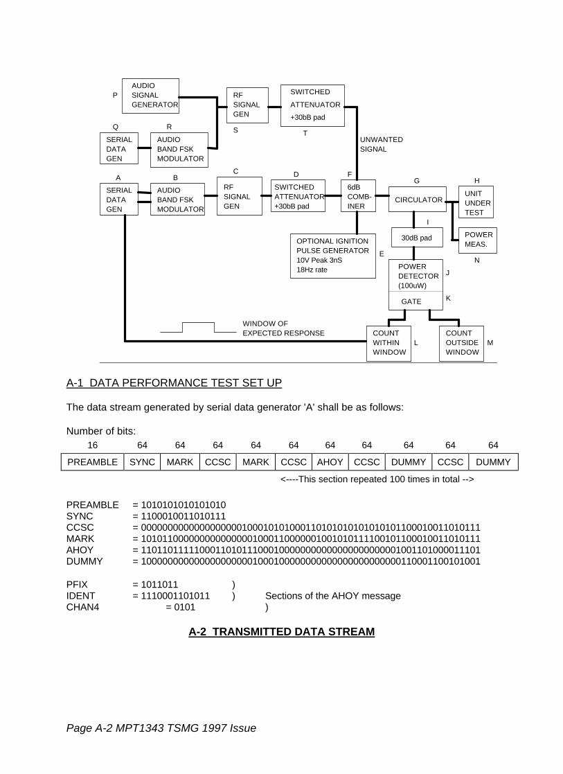
Page A-2 MPT1343 TSMG 1997 Issue
AUDIOSIGNALGENERATOR
RFSIGNALGEN
SWITCHED
ATTENUATOR
+30bB pad
UNWANTEDSIGNAL
SWITCHEDATTENUATOR+30bB pad
RFSIGNALGEN
AUDIOBAND FSKMODULATOR
AUDIOBAND FSKMODULATOR
SERIALDATAGEN
6dBCOMB-INER
CIRCULATORUNITUNDERTEST
POWERMEAS.
POWERDETECTOR(100uW)
GATE
SERIALDATAGEN
30dB padOPTIONAL IGNITIONPULSE GENERATOR10V Peak 3nS18Hz rate
P
Q R
A BC D
E
FG H
I
J
K
L M
N
S T
COUNTOUTSIDEWINDOW
COUNT
WINDOWWITHIN
WINDOW OFEXPECTED RESPONSE
A-1 DATA PERFORMANCE TEST SET UP
The data stream generated by serial data generator 'A' shall be as follows:
Number of bits:16 64 64 64 64 64 64 64 64 64 64
PREAMBLE SYNC MARK CCSC MARK CCSC AHOY CCSC DUMMY CCSC DUMMY
<----This section repeated 100 times in total -->
PREAMBLE = 1010101010101010SYNC = 1100010011010111CCSC = 0000000000000000000100010101000110101010101010101100010011010111MARK = 1010110000000000000001000110000001001010111100101100010011010111AHOY = 1101101111100011010111000100000000000000000000001001101000011101DUMMY = 1000000000000000000001000100000000000000000000000110001100101001
PFIX = 1011011 )IDENT = 1110001101011 ) Sections of the AHOY messageCHAN4 = 0101 )
A-2 TRANSMITTED DATA STREAM

MPT1343 TSMG 1997 Issue Page A-3
The window of expected response is defined in MPT 1327, section 6 (pages 6-7). Theboundaries of the window are 20 bits and 14 bits after the start of CCSC as shown below:
AHOY CCSC DUMMY CCSC DUMMY
¬¾®
20 bits ¬¾®
14 bits
EXPECTED TRANSMISSION
Following the transmission of the data stream of Figure A-2, count 'L' and count 'M' shallbe recorded. Between each test listed below in A.3, the counters are reset.
A.3 Limits
A.3.1 Test 1
Test conditions:
i. Transmit power level A.ii. Ignition simulator switched OFF.iii. Co-channel interference switched OFF.
Count 'L' shall be not less than 99.Count 'M' shall be zero.
A.3.2 Test 2
Test 2 is optional.
Test conditions:
i. Transmit power level A.ii. Ignition simulator switched ON.iii. Co-channel interference switched OFF.
Count 'M' shall be zero. Count 'L' shall be not less than 89.
A.3.3 Test 3
Test conditions:
i. Transmit power level B.ii. Ignition simulator switched OFF.iii. Co-channel interference switched OFF.
Count 'L' shall be not less than 89.Count 'M' shall be zero.
Page A3-4 MPT1343 TSMG 1997 Issue
A.3.4 Test 4
Test conditions:
i. Wanted signal transmit power level C.ii. Ignition simulator switched OFF.iii. Co-channel interference switched ON.
Audio signal generator 'P' shall be used to inject a frequency of 400Hz. RF signalgenerator 'S' shall modulate the signal to 60% of the maximum peak frequency deviationdesignated in section 5.3.2 of MPT 1323. The level of unwanted signal, as set byattenuator 'T', shall be 10dB below the level of the wanted signal supplied throughattenuator 'D'.
Count 'L' shall not be less than 89.Count 'M' shall be zero.
The test shall be repeated with the carrier generated by RF signal generator 'S' offset by±1200 Hz from the nominal frequency.
Count 'L' shall not be less than 89.Count 'M' shall be zero.
A.3.5 Test 5
Test conditions:
i. Wanted signal transmit power level C.ii. Ignition simulator OFF.iii. Co-channel interference switched ON.
Serial data generator 'Q' shall be used to generate a 511 bit test pattern, in accordancewith CCITT recommendation V52, at a rate of 1200 bits/second. This pattern is then fedto audio band FSK modulator 'R' to provide an FFSK signal in compliance with section 6.1of MPT 1323. RF signal generator 'S' shall modulate the signal to 60% of the maximumpeak frequency deviation designated in section 5.3.2 of MPT 1323. The level of theunwanted signal, as set by attenuator 'T', shall be 10dB below the level of the wantedsignal supplied through attenuator 'D'.
Count 'L' shall not be less than 89.Count 'M' shall be zero.
The test shall be repeated with the carrier generated by RF signal generator 'S' offset by±1200 Hz from the nominal frequency.
Count 'L' shall not be less than 89.Count 'M' shall be zero.

MPT1343 TSMG 1997 Issue Page A-5
A.3.6 Test 6
Test conditions:
i. Transmit power Level A.ii. Ignition simulator OFFiii. Co-channel interference switched OFF.iv. The prefix/ident section of the AHOY codewords is selected to differ by 1 the
prefix/ident of the unit. The parity is then set to give a valid codeword. Thelocation of the bit difference is changed for successive AHOY codewords so thateach of the 20 bit differs are sent 5 times in the stream of 100 AHOY messages.
The list of modified AHOY codewords is as follows:
10011011111000110101110001000000000000000000000011101110000101101111101111100011010111000100000000000000000000000100100000001101110010111110001101011100010000000000000000000000111100110001010111010011111000110101110001000000000000000000000010101110100110011101111111100011010111000100000000000000000000001000000001011111110110011110001101011100010000000000000000000000011111110010100011011010111000110101110001000000000000000000000011101000100001101101101101100011010111000100000000000000000000000100101101000101110110111010001101011100010000000000000000000000111100101011000111011011110000110101110001000000000000000000000010101110010010111101101111110011010111000100000000000000000000000110100000100010110110111110101101011100010000000000000000000000000010110001011111011011111001110101110001000000000000000000000000111010100011001101101111100001010111000100000000000000000000001100101001010100110110111110001001011100010000000000000000000000101100100011100011011011111000111101110001000000000000000000000010001110000011101101101111100011000111000100000000000000000000000111100000000001110110111110001101111100010000000000000000000000111010110001001111011011111000110100110001000000000000000000000001001010100011101101101111100011010101000100000000000000000000000001101001000001
Count 'L' shall be zero.Count 'M' shall be zero.


MPT1343 TSMG 1997 Issue Page B-1
APPENDIX B: TIMING AND DEFAULT PARAMETERS
B.1 Default Parameters
TimingParameter
MPT1327default
MPT1343Value
Function
ND1 2 3 Number of disconnect messages sent byindividually addressed radio unit
ND2 4 5 Number of disconnect messages sent by callingradio unit
NE 16 16 Maximum number of random accesstransmissions of RQE
NI 4 4 Maximum number of include request accessattempts
NR 8 8 Maximum numberof random accesstransmissions of RQS, RQD, RQX, RQT, RQRor RQQ
NW 4 5 Response delay (in slots)
The requirement for the storage of parameters that may vary from network to network such asLA, LZ, NC1, NC2, NT, NV1, NV2, NX1, NX2, NZ1 and NZ2 are specified in section 6.

Page B-2 MPT1343 TSMG 1997 Issue
B.2 Timing Parameters
TimingParameter
MPT1327default
MPT1343Value
Function
TB 2 s 2 s Time barred from calling same ident afterACK/ACKX/ACKV or any ident afterACKT/ACKB
TF 180 s Value of TS in fall-back mode
TI 2 s 2 s Include timer
TP 5 s 5 s Maximum interval between periodic messages(within speech items) to be assumed at switch-on or equivalent
TX 180 s Value of TC in fall-back mode
TR 500 ms Call set-up Data Keyline delay
The requirements for the storage of timing parameters which may vary from network tonetwork such as TA, TC, TD, TJ, TN, TS, TGG, TGI, TT and TW are specified in section 6.
MPT1343 TSMG 1997 Issue Page AN1-1
ANNEX AN1 CLARIFICATION OF RADIO UNITOPERATION ON TIME SHARED CONTROLCHANNELS
In this specification the term "time-shared control channel" refers to a control channelwhere multiple base station transmitters (whether co-sited or multi-sited) share one radiofrequency for control purposes by dividing the use of the frequency in time. Each period oftransmission from a base station transmitter is referred to as a burst.
For clarity, multi-site time-shared control channels are assumed in this Annex.
AN1.1 Purpose of ANNEX
The purpose of this annex is to clarify and explain the activity of radio units when operatingon time-shared control channels whilst complying with section 9 of this specification. Itdoes not, in itself, constitute a part of the requirements of this specification and does notchange the requirements of this specification in any way.
The matters discussed as relevant are:
- the general principles of the detection of synchronisation loss and subsequent re-synchronisation,
- error checking on a control channel,
- control channel acquisition
and
- the use of SYS codes on time-shared control channels.
AN1.2 Identification of, and operational changes on, time-shared control channels
This specification recognises that particular problems apply in making valid errormeasurements on time-shared control channels. These problems occur during samplingprior to confirmation and during continuous monitoring after confirmation. They areassociated with discontinuous reception of the forward control channel which the radio unitis likely to encounter.
One mechanism which can be employed by network operators to compensate for theseproblems is to select the values of NV, NC, NX and NZ accordingly. Thus a networkoperator employing time-shared control channels may specify quite different values ofthese parameters from one employing continuous control channels, and the allowableranges of these parameters have been set accordingly. The use of this mechanism wouldhowever be problematic for a network operator employing a mix of continuous and time-shared control channels, since he may wish to specify different parameter values for eachtype of channel. This problem is foreseen by this specification, and two sets of the
Page AN1-2 MPT1343 TSMG 1997 Issue
parameter values (one for time-shared control channels and one for continuous controlchannels) may be set in the radio unit. The radio unit uses the values appropriate to acontinuous control channel unless it has reason to believe that the control channel beingmonitored is time-shared.
To facilitate this, each channel in the normal hunt list is marked by a time-shared flag(named TSI) which also appears in MOVE messages, CLEAR messages and any BCASTmessage which may identify a control channel for possible later use by the radio unit.BCAST (SYSDEF = '00000'), BCAST (SYSDEF = '00100') and BCAST(SYSDEF = '00101'). The flag causes the radio unit to change the following operatingparameters when set to the "time-shared" state:
NV - Number of consecutive received CCSCs to select a value of SYS forverification,
NC1 - size of error check sample prior to confirmation,
NX1 - error codeword limit prior to confirmation,
NC2 - size of error check sample after confirmation,
NX2 - error codeword limit after confirmation.
NZ1, NZ2, NC1, NX1, NC2 and NX2 are employed in the error analysis procedures usedfor control channel acquisition and control channel quality monitoring purposes. Their useis discussed in detail in section AN1.4.
NV is used in control channel acquisition and is further discussed in section AN1.5.
Another operational difference is that a time period TS is mandated for use when searchingfor a valid SYS code during control channel identification on time-shared control channels(see 9.3.4.1). No specific time value is mandated for continuous control channels. Thisoperational difference is detailed in section AN1.5.
AN1.3 Synchronisation loss and subsequent re-synchronisation
Each reference to a control channel in this section (AN1.3) of this Annex applies to onewhich has already been verified and references to codewords apply to codewords after anyerror correction has been performed. The rules defined in 9.3 and 9.4 override any of thedescriptions in this section ie if a criterion for rejecting or relinquishing the channel is metany attempt at re-synchronisation is abandoned.
AN1.3.1 Discontinuous control channels
!!6.2.1.2!! states that a radio unit shall be capable of satisfactory operation on a controlchannel which has interruptions of duration less than TS seconds (where slot timing mightnot be maintained across interruptions) and where CCSCs are displaced by datacodewords in up to two consecutive time slots. Section 11.6.2.1.2 states that !!6.2.1.2!! ismandatory as specified. The title of this section in MPT 1327 is "Retaining a control
MPT1343 TSMG 1997 Issue Page AN1-3
channel" and therefore an MPT 1343 radio unit shall not relinquish such a channel unlessthe criteria specified in 9.4 are met.
Some clarification is required here to indicate how a radio unit can cope with suchinterruptions in a control channel and continue with the error checking defined in 9.3.4.3.This explanation is more general and covers interruptions in reception of control channelsignalling across which synchronisation is not guaranteed. It is pertinent to both continuousand discontinuous control channels and therefore also to time-shared control channels.
In order to cope with the above situation a radio unit must have some means of determiningthat synchronisation has been lost and some means of re-synchronising on that channel.
It is considered that the guidelines for achieving synchronisation in 9.3.4 are adequate.The procedures for synchronisation are employed when identifying a candidate controlchannel whilst hunting. The procedures for re-synchronising are employed wheneversynchronisation has been lost on a control channel.
AN1.3.2 Criteria for determining synchronisation loss and subsequentre-synchronisation
A radio unit may lose bit synchronisation, codeword synchronisation or slot synchronisation.There is no concept of frame synchronisation: a radio unit considers itself either to be in aframe or not to be in a frame. It is important to note that, when performing a randomaccess attempt, a radio unit must maintain information regarding its slot position within aframe. This information must be maintained even if the radio unit transmits data(see !!7.3.5!! para. 2) or loses synchronisation (no allowances are made for loss ofsynchronisation in the random access rules).
A radio unit operating to MPT 1327 must have the capability of determining thatsynchronisation with the received control channel data has been lost or is no longerguaranteed and must also have the capability of re-synchronising without losing the slotnumbering information of the currently monitored frame, if any.
If slot synchronisation is monitored by the radio unit and some mechanism detects loss ofslot synchronisation then a bit or codeword re-synchronisation procedure may commence.This process would also cope with loss of bit and loss of codeword synchronisation aseither of these would cause loss of slot synchronisation and would be detected andcorrected in the same way. If bit synchronisation cannot be guaranteed the re-synchronisation procedure should commence at the bit synchronisation stage otherwise there-synchronisation procedure can commence at the codeword synchronisation stage. Ineach of these cases slot re-synchronisation would be achieved provided that controlchannel data is receivable. It should be noted that detection of synchronisation loss andsubsequent re-synchronisation should be optimised when on time-shared control channelsas a radio unit should detect the end of a control channel data burst as soon as possible.Such a mechanism may cause re-synchronisation to take place frequently and analternative mechanism may be employed on non time-shared control channels to reducethis effect.
Page AN1-4 MPT1343 TSMG 1997 Issue
The criteria for determining that synchronisation has been lost are not specified inMPT 1327 or section 9. One such mechanism for determining loss of slot synchronisationcould be as follows.
Check the first codeword in the slot, if the codeword is not decodable and the CRC doesnot contain the SYNC pattern then assume that synchronisation has been lost but continueto attempt to decode codewords on the basis of the last SYNC received until a new SYNCis received; the exception to this is where the radio unit, from interpretation of messages onthe forward control channel (eg the receipt of a HEAD codeword), expects the codewordnot to be a CCSC as the result of displacement of the CCSC by a data codeword and thusdoes not regard failure of the CRC to match the SYNC pattern as a loss of synchronisation.(It should be noted that this strategy carries the risk that, if the radio unit is unable to predictthe displacement of a CCSC by a data codeword and that codeword is received corrupted,it may seek to re-synchronise unnecessarily and could find SYNC mimicked within asubsequent codeword. However such false synchronisation should be rare and shouldsoon be detected and rectified by the radio unit). Also, in addition to the above criteria, theradio unit may assume loss of synchronisation if the first codeword in the slot is decodableand the most significant bit is '1'.
Even when a radio unit assumes that synchronisation has been lost it shall continue toconsider each consecutive group of 64 bit positions to be a codeword. It shall continue toperform any error analysis which may be in progress whilst at the same time scan forsynchronisation. Achieving re-synchronisation does not reset any error count in progress.Any incompletely received codeword at the time when re-synchronisation is achieved maybe, for the purposes of any error analysis, either considered as an errored codeword orignored.
AN1.4 Error checking on a control channel
AN1.4.1 Error checking philosophy
This specification employs the measurement of codeword error rates as the means ofassessing the received control channel quality. This is convenient since the radio unit isrequired by the protocol to attempt to decode every received codeword when it is tuned tothe forward control channel and the first step in this process is to validate the errorchecking sequence in bits 49 to 64. Thus the radio unit is equipped for codeword errorchecking by virtue of meeting the basic requirements of MPT 1327. The codeword errorrate is determined by successive counts of blocks of codewords; the number of codewordswhich fail the validation of the error checking sequence in any block being the measure ofthe codeword error rate.
Since the error checking sequence employed by MPT 1327 provides some capability forerror correction, MPT 1343 allows the radio unit to count any corrected codeword asunerrored.
An essential feature of the error monitoring procedures specified by this specification is thatmonitoring, once started, is a continuous process until stopped or suspended for someother reason (eg the radio unit leaves the control channel). Thus even when the radio unitis unable to detect recognisable signals on the received control channel (eg it fails toreceive the codeword synchronisation sequence) it is required to continue the assessment

MPT1343 TSMG 1997 Issue Page AN1-5
until such time as the radio unit determines that it should relinquish the channel, accordingto the rules of this specification. It does this by retaining the bit, codeword and slot timingwhich it last received from the forward control channel prior to loss of signal. On the basisof this retained timing every first and second half of each slot is examined for a codeword.Failure to decode a codeword, for any reason, is recorded as a codeword error.
AN1.4.2 Summary of error checking procedures on a control channel
The radio unit employs three parameters to control the manner in which error monitoring iscarried out. These are NC, NX and NZ:
- NC is the number of contiguous positions in which codewords are expected (ie thefirst and second halves of slots) which shall be monitored in each codeword sample.
- NX is the number of errored codewords which must be exceeded in the count of NCcodewords before the sample of NC codewords is considered as yielding acodeword sample error event.
The combination of NC and NX, accordingly, set the error threshold at which the controlchannel performance is considered inadequate. In order to allow different error criteria tobe applied to the assessment of a control channel for sampling during hunting and to thecontinuous monitoring after confirmation to determine when the radio unit should relinquishthe channel,two values of NC and NX are specified. Parameters NC1 and NX1 areemployed for sampling during hunting and NC2 and NX2 are employed for the continuousmonitoring after confirmation. The values of these would normally be selected by thenetwork operator to provide a more stringent error performance requirement for samplingduring hunting than for the continuous monitoring after confirmation.
A further parameter NZ is specified to allow further samples to be taken to improve theaveraging of the error sample. As with NC and NX to values are specified, NZ1 and NZ2,but as well as having possible different values, NZ1 and NZ2 are employed differently inthe error monitoring process:
NZ1 is employed by the radio unit for error checking when sampling during hunting. It isthe number of contiguous samples of NC1 codewords without a codeword sample errorevent which must be recorded before the control channel being sampled may beconfirmed.
NZ2 is employed by the radio unit for error checking when sampling during continuousmonitoring of the control channel after confirmation. Following the first sample error eventit is the number of further contiguous samples of NC2 codewords each with a codewordsample error event, which must be recorded before the radio unit may relinquish the controlchannel on the grounds of unacceptable codeword error rate.
AN1.4.3 Examples of error checking on time-shared control channels
This section considers the possible application of the error monitoring procedures providedby this specification. Figure AN1.1 illustrates a simple time-shared control channelprovided by three sites with an equal duration burst from each site (equivalent to twenty
Page AN1-6 MPT1343 TSMG 1997 Issue
codewords). There is a blank period between any two bursts of duration equivalent to fivecodewords to accommodate tolerances and equipment switching delays.
Four samples of the forward control channel, as received by the same radio unit at differentinstances of time, are shown in the figure and are labelled Case I, Case II, Case IIIand Case IV. Each of these samples starts at the instant immediately before the nexttransmission. The sample duration is therefore 75 codewords (20 + 5 + 20 + 5 + 20 + 5).
In the figure, codewords received by the radio unit unerrored are indicated by white andthose received errored are indicated by black. Since the blanks between transmissions willbe interpreted by the radio unit as errored codewords these blanks are coloured black inthe figure.
In Case I the radio unit is receiving a good signal (one errored codeword) from site B but nosignal at all from sites A and C.
In Case II the radio unit is receiving a good signal from site B (one errored codeword) andinadequate signals from A and C (eight errored codewords each).
In Case III the radio unit is receiving an approximately equal quality of signal from all threesites (A has four errored codewords, B seven and C six). It is assumed for this examplethat this level of errored codewords is too high for reliable communication with any site.
It should be noted that, whilst II and III represent totally different situations, the total numberof errored codewords received in the sample taken by the radio unit is equal (31 in eachcase).
In Case IV the radio unit is receiving a good signal from two of the sites (B and C) and aninadequate signal from site A.
The case of a radio unit error monitoring after confirmation shall be considered, with NC2set to 75 to correspond to the sample length. The network operator is required to select anappropriate value of NX2. In calculating this value it seems appropriate to consider Case I,since this is likely to be a common occurrence. If it is assumed that three erroredcodewords in any burst from a single site represents the maximum tolerable error level,then in order to detect this level in the burst from site B the value of NX2 should be setto 58 (ie assuming all errored codewords outside the burst from site B plus three within theburst = 55 + 3).
If it is assumed that sites A, B and C all radiate the same value of SYS code then a radiounit set with NC2 = 75 and NX2 = 58 will not register a codeword error event in Case I. Itwill also not register such an event in Case II, since the number of errored codewords willbe 31. The same will be true of Case III. This is clearly an undesirable result since theradio unit should register a codeword error event in Case III because reliablecommunication is not likely. It is clear that whatever the chosen value for NX2, the radiounit will not be able to differentiate between cases II and III.
This problem may be solved if the three sites radiate different values of SYS code.Assuming that the radio unit holds the value radiated by site B as the valid value of SYS,then it will count as errors all codewords received from sites A and C, irrespective of the
MPT1343 TSMG 1997 Issue Page AN1-7
actual received condition. In Case III this will result in a total error count of 62 codewordsresulting in a codeword error event. In Case II the error count will be 56 which will notresult in a codeword error event. Thus the required differentiation between cases II and IIIwill be achieved.
However, this solution does have a disadvantage which is illustrated by Case IV. Here theradio unit has an equal choice of two sites (B and C). If all sites radiate the same value ofSYS code then the radio unit may access either site thus doubling the total time available toit for system access. If, however, the three sites radiate different SYS codes the radio unitwill not be able to access both sites B and C (since the value of SYS received from onlyone of those sites will be the one used in verification - refer to 9.4.1(b)) and will thus not beable to take advantage of the increased access time offered.
AN1.5 Control channel acquisition
The operational differences between a radio unit acquiring a time-shared control channel(ie one which the radio unit expects to be time-shared) and a radio unit acquiring acontinuous control channel are as follows:
the use of NV;
the time period mandated in searching for a valid SYS code prior to verification;
error analysis.
The third issue was explained in section AN1.4 and the earlier two are explained here (referto section 9.3.4.2.1).
When a radio unit is searching for a valid control channel codeword synchronisationsequence on a time-shared control channel prior to verification it should search for a periodlong enough to allow the radio unit to receive at least one complete burst from each siteirrespective of the point at which synchronisation is originally obtained. The value TS isused by the radio unit to measure this time period and it therefore must be selected by thenetwork operator to enable this to happen. No such time period is mandated for operationon a continuous control channel prior to verification.
A mechanism is mandated which enables the radio unit to select a good site on which toattempt verification. For a time-shared control channel which employs differing SYS codesthis mechanism involves the radio unit receiving a predetermined number of identical SYScodes derived from consecutive (but not necessarily from contiguous slots) unerroredCCSCs prior to verification.
Using the examples in Figure AN1.1 where each site radiates a different SYS code andusing an example value of NV (time-shared value) of 9 the following behaviour can beobserved.
In Case I the radio unit will not begin verification until 9 CCSCs containing the same SYScode have been received. The radio unit may have to receive more than one burst fromsite B to receive 9 CCSCs; this depends upon when the radio unit acquires synchronisationon the channel.
Page AN1-8 MPT1343 TSMG 1997 Issue
In Case II the radio unit will again select the system on site B for verification as it will notreceive 9 consecutive CCSCs containing the same SYS code from either site A or site C.
In Case III the radio unit will not receive 9 consecutive CCSCs containing the same SYScode and will reject the channel after TS seconds.
In Case IV the radio unit will select the system on either site B or site C for verificationdepending upon when it acquires synchronisation.
It can therefore be seen that on such a system, a value of NV should be selected by thenetwork operator which is low enough to allow channel acquisition and is high enough tomake the radio unit select a good site.
On channels where only one SYS code is used it is expected that the selected value of NVwill be low to allow faster channel acquisition.
AN1.6 Use of SYS codes on time-shared control channels
Note that not all situations are considered here.
AN1.6.1 Comparison of the received and verified SYS codes
The value of SYS code used for each site operating the time-shared control channel isnetwork dependent. The radio unit shall decode the received SYS code in accordance withSection 9.3.4 and shall compare the received SYS code with that verified during controlchannel acquisition authorisation in accordance with section 9.4.1(b). If bits 1-12 of theSYS code recovered from decodable control channel system codewords received differsfrom the value of the bits verified during acquisition authorisation the radio unit shallcontinue error checking and suspend any random access attempts in accordance withsection 9.3.4.3 and 9.4.1(b) respectively. Irrespective of bits 1-12, if there is anydiscrepancy in the LAB field (bits 13-15) the radio unit should act in accordancewith 9.4.1(g). It is expected that network operators will use the same value of the LAB fieldon all sites on a time-shared control channel.
One effect on the radio unit of different sites using different SYS codes should be noted: itwill only act upon signalling from one of the sites on an acquired control channel. This isbecause when a radio unit acquires such a channel it commences or continues a sessionon only one of the systems (ie one of the sites) and it will not therefore act upon any of thecodewords from the other sites (see 11.6.2.1.2) except that it will treat them as erroredcodewords during error analysis (see section 9.3.4.3).
AN1.6.2 Requirements to register
Use of a different SYS code at sites on the time-shared control channel may result in theradio unit registering as it roams (as the unit relinquishes and acquires the control channelfrom the different sites). The radio unit shall attempt to register on the confirmed channel(by random access) when it does not hold a successful registration record for the AREA
MPT1343 TSMG 1997 Issue Page AN1-9
field within the verified SYS code (section 9.3.4.2.2), provided that this AREA field is notalready entered in the unit's list of denied registration records (section 10.3).
The radio unit shall not attempt to register at sites radiating a zero value AREA field(section 10.2.3i. and 10.3.3i.) or when the radio unit is personalised with a zero lengthAREA field (section 10.3.(i)). If the sites sharing the time-shared control channel areradiating SYS codes differing only in the value of the FREE bits (see section 9.3.4.2.2) theradio unit shall not be required to register as it roams from site to site.

Page AN1-10 MPT1343 TSMG 1997 Issue
TRANSMISSIONS FROM SITES
SITE A SITE B SITE C
RECEIVED CODEWORDS
RECEIVED CODEWORDS
RECEIVED CODEWORDS
RECEIVED CODEWORDS
CASE I
CASE II
CASE III
CASE IV
Key
Decodeable Codeword
Errored Codeword
Figure AN1-1 Time-shared Control Channel Example
MPT1343 TSMG 1997 Issue Page AN2-1
ANNEX AN2 RECOMMENDATION FOR RADIO UNITBEHAVIOUR ONCE THE COMPREHENSIVEHUNT SEQUENCE HAS BEEN ENTERED
Section 9.3.3.5 of this Specification allows a radio unit in the process of undertaking a"comprehensive hunt sequence" to carry out a "preferential hunt sequence" or "normal huntsequence" as its own option, returning to the "comprehensive hunt sequence" if theoptional sequence is unsuccessfully completed. Experience with operational systems hasled to the following recommendation regarding the exercise of this option.
"The exercise of the option to undertake other hunting sequences whilst in the'comprehensive hunt sequence' is recommended since it can be expected that the timetaken to acquire a control channel during a 'comprehensive hunt sequence' may be muchlonger than in other hunting sequences. Failure to exercise this option may result inexcessive delays in acquiring one of the control channels applicable to the 'normal huntsequence' (ie a 'normal' control channel for the selected network) following the temporaryloss of the current control channel. It should be noted, however, that the exercise of theoption will have the effect of further extending the time taken to complete a 'comprehensivehunt sequence' and that the intervals at which a normal or preferential hunt sequence isperformed should be chosen with care."

MPT1343 TSMG 1997 Issue Page AN3-1
ANNEX AN3 IMPORTANT NOTES REGARDINGACQUIRING AND RELINQUISHING ACONTROL CHANNEL
Introduction
This annex describes an issue relating to the acquisition and relinquishment of controlchannels by radio units.
Radio units should be confirmed for the optimum performance on the given network, as aminimum to ensure there is reciprocity with the TSC on a control channel and that the unitdoes not “hang on” to unusable sites. Operational experience has now shown the use ofmandatory personalisation data, i.e.: error parameters alone is insufficient to ensureadequate operation in some circumstances, particularly when the radio unit has a verysensitive receiver.
In this annex, the problem is described and possible solutions are proposed. Radio unitmanufacturers are advised that it may be essential to incorporate such a solution intoa unit to ensure reciprocity and adequate call quality on some networks. Someschemes which may be proprietary are permitted within the scope of section 9.1.
The Problem with Sensitive Receivers
The rapid progression in RF technology has led to the receivers in new radios beingcapable of providing good SINAD figures at very low received carrier levels. This leads tobetter error rates at low received signal levels. The error rate is further enhanced if forwarderror correction is used.
Radio units exhibiting such characteristics can acquire or remain confirmed on a controlchannel even when a large geographical distance exists between the radio and the basestation. This can lead to reciprocity problems, noisy calls and potentially to co-channelinterference with other sites re-using the same frequency. In areas where coverage mayoverlap, a better quality of service may be available to the radio from a closer site. Toobtain service on the new site the radio must first relinquish the control channel on which itis currently confirmed. If the received error rate is very low rate then the error checkingalgorithms of NC1, NX1, NZ1 and NC2, NX2, NZ2 become ineffective and the radio cannotbe forced to leave the control channel until the received signal level is extremely low.
Solutions
Use of Background Search Sequence
Personalising a radio with a background search sequence enabled is one method whichcan be employed. This is only effective however, when a better control channel is likely tobe available. It must also be noted that :-
Page AN3-2 MPT1343 TSMG 1997 Issue
If a radio unit leaves the control channel in an attempt to locate an alternative one,there is a period when it is unable to receive calls. The Network believes that theradio unit is active on a particular site from its registration record and does notknow when the radio unit will initiate a background hunt. A period betweenbackground hunts must be chosen very carefully. This will be related to thecoverage area and the speed at which the radio unit is moving through thecoverage area.
Use of Programmable RF Threshold Level
An alternative method is to allow radio units to acquire and relinquish a control channel bythe use of a programmable RF threshold level. When a radio unit is located near the edgeof the coverage area, the received signal strength is subject to fluctuations due to the multi-path reception. If an RF threshold is used to determine if a channel will be relinquished,one sample will not be sufficient. Several samples must be taken over a period of time andan average or statistical measurement taken. The period is dependant on characteristics ofthe multi-path.
User Services vs. Network Optimisation
The solutions proposed in this annex should be applied, where necessary, to ensureadequate operation of the radio unit on the network.
Beyond this, manufacturers are reminded that user service and network optimisation oftenconflict, with the overall aim being to offer the best service for the user while maintainingthe infrastructure performance.
The Network operator will wish to maximise the network loading by encouraging radio unitsto make single-site rather then multi-site calls (only one traffic pair and no lines used for thecall) which may be achieved by background searching in the radio unit. Note that in thiscase the radio unit would be encouraged to relinquish a strong site for a weaker (but stilladequate) site transmitting the PREFERRED NDD.
MPT1343 TSMG 1997 Issue Page AN4-1
ANNEX AN4 NOTES RELATING TO THE USE OF THEINFO FIELD IN REQUEST TO REGISTERRQR MESSAGE
AN 4.1 Introduction
The INFO field in the RQR message provides additional information to be conveyedfrom the radio unit during registration. This information may be -
a) Additional information that the radio unit wishes to convey to the TSCregarding the radio unit type or personalisation.
b) Additional information gleaned from the TSC. Registration attempts from theradio unit may be heard by TSC sites other than the site intended, resultingin a misdirected registration. The use of part of the SYS provides additionalsecurity against misdirected registrations.
AN 4.2 Misdirected Registrations
For Networks with sites employing the same Control Channel, under certaincircumstances and RQR may be received by more than one TSC. Similarly the RQRmay be received by the TSC of another Network. The result may be erroneousregistration records being stored within a Network. Some security against thisphenomena may be achieved by transmitting part of the System Identity Codecurrently being propagated by the TSC within the INFO field of the RQR message.
Note that 11.5.5.3.1.6 MPT1343 statesThe "Info" field shall be set to all zeros, unless permitted otherwise by the network
INFO-FIELD in RQR
SYL ESNF RSVD SIF SPARE6 1 2 1 5
SIF - If non zero then SYL holds a subset of the OPID and/or the NDD sub field of the system identity code (SYS) currently being propagated by the system originating the message.
SYL - With bit 1 of the SYS field set to '1' (indicating that the Network is a National Network), SYL contains the six least significant bits of the NDD sub field of the system identity
code appropriate to the system originating the message.
With bit 1 of the SYS field set to '0' (indicating that the Network is aRegional Network), SYL contains the two least significant bits of theOPID field concatenated to the four bits of the NDD sub field of thesystem identity code appropriate to the system originating themessage.

Page AN4-2 MPT1343 TSMG 1997 Issue
OPID NDD
SYL
For SIF='0' then SYL='000000'
ESNF - Electronic Security Number Flag. See Section 10.2.3
RSVD - Reserved for future definition. Default='000'
A TSC which incorporates the SYL feature shall examine the SIF flag within the INFO fieldof any registration request.
If the SIF flag is non zero then:
The TSC shall only acknowledge the registration request if the SYL field matchesthe least significant six bits of the NDD field of the System Identity Code beingpropagated by the system originating the message.
If the SIF flag is zero then:
The TSC shall acknowledge the registration request. If the TSC is not equipped tomake use of the INFO field in the RQR message, then it may reject the RQR bytransmitting an ACKX (Q=0) in response to the registration attempt.
MPT1343 TSMG 1997 Issue Page AN5-1
ANNEX AN5 NOTES REGARDING THE IMPLEMENTATIONOF REGISTRATION ON DEMAND IN RADIOUNITS. ISSUES OF NETWORKCOMPATIBILITY.
INFORMATIVE
The information given in this annex is important for any radio unit manufacturer planning toimplement a radio unit for use on any MPT1343 compliant work. It is particularly importantif the radio unit design is planned to be used on more than one network.
The radio unit manufacturer should be aware that somewhat different behaviour may beexpected of the radio unit by different networks when a demanded registration takes place.This is dependent upon which issue of MPT1343 the particular network concerned isconforming to.
The earlier version of MPT1343 (1988) contained the following text in its specification of theexpected radio unit behaviour when a demand for registration was received.
"If, while confirmed on a control channel and not attempting to register by randomaccess, a radio unit receives an applicable individually addressed ALHR, it shallattempt to register, complying with the procedures defined in MPT 1327section 8.23.2.
Provided that the prime registration record is not already a NULL containing thesame AREA code as the currently verified AREA code, then upon making aregistration attempt (as a result of a demand) the radio unit shall:
a) Change the prime registration record into a timed record with a newly-startedtimer, deleting, if necessary, the registration record closest to expiry (seesection 10.6), and
b) Create a NULL record as the prime registration record.
The radio unit action after transmitting RQR upon demand, whilst not attempting toregister by random access, shall be as defined in sections 10.4.2.1 and 10.4.2.3."
Note that a network which has been implemented to make use of this earlier version of theMPT 1343 specification (1988 version) will require the radio unit to handle its prime andtimed registration records differently to one which has been implemented to the 1991version.
Radio unit manufacturers wishing to ensure that their radio equipment is compatible with aparticular network are advised to check this particular issue with the network operator. Forradio equipment which is likely to be required to operate on more than one network, theequipment manufacturer may wish to make appropriate design decisions which will enablethis matter to be configured for the different network types.

Page AN5-2 MPT1343 TSMG 1997 Issue
Those manufacturers who implement both the 1988 and 1991 methods of registrationshould also include a proprietary Network Personalisation Flag to control the form ofregistration that the unit operates.
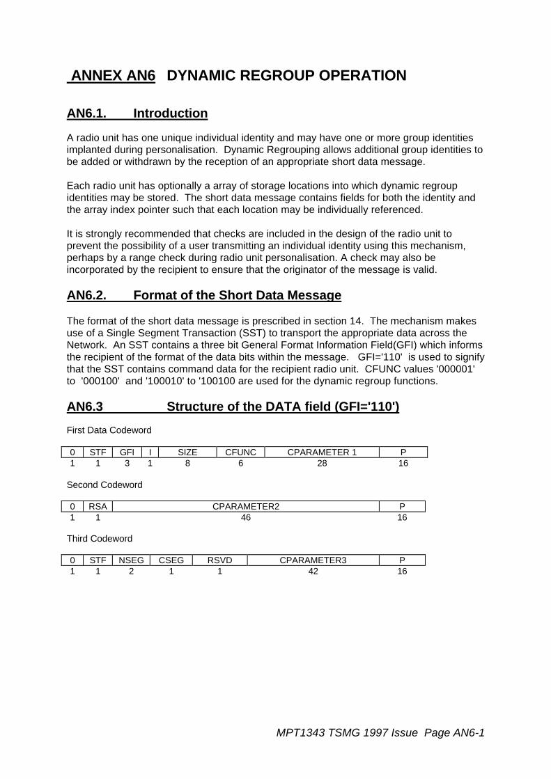
MPT1343 TSMG 1997 Issue Page AN6-1
ANNEX AN6 DYNAMIC REGROUP OPERATION
AN6.1. Introduction
A radio unit has one unique individual identity and may have one or more group identitiesimplanted during personalisation. Dynamic Regrouping allows additional group identities tobe added or withdrawn by the reception of an appropriate short data message.
Each radio unit has optionally a array of storage locations into which dynamic regroupidentities may be stored. The short data message contains fields for both the identity andthe array index pointer such that each location may be individually referenced.
It is strongly recommended that checks are included in the design of the radio unit toprevent the possibility of a user transmitting an individual identity using this mechanism,perhaps by a range check during radio unit personalisation. A check may also beincorporated by the recipient to ensure that the originator of the message is valid.
AN6.2. Format of the Short Data Message
The format of the short data message is prescribed in section 14. The mechanism makesuse of a Single Segment Transaction (SST) to transport the appropriate data across theNetwork. An SST contains a three bit General Format Information Field(GFI) which informsthe recipient of the format of the data bits within the message. GFI='110' is used to signifythat the SST contains command data for the recipient radio unit. CFUNC values '000001'to '000100' and '100010' to '100100 are used for the dynamic regroup functions.
AN6.3 Structure of the DATA field (GFI='110')
First Data Codeword
0 STF GFI I SIZE CFUNC CPARAMETER 1 P1 1 3 1 8 6 28 16
Second Codeword
0 RSA CPARAMETER2 P1 1 46 16
Third Codeword
0 STF NSEG CSEG RSVD CPARAMETER3 P1 1 2 1 1 42 16

Page AN6-2 MPT1343 TSMG 1997 Issue
Fourth Codeword
0 RSA CPARAMETER4 P1 1 46 16
Fields defined in Section 14 of MPT1343
STF - '1' MPT1343 format messageGFI - '110' Format of the message as defined in this AnnexI - '1' Initial segment flag always set to '1' for
an SSTRSA - '0' if the codeword is the last codeword in this message
otherwise set to '1'NSEG - '00' for an SSTCSEG - '0' for an SSTP - MPT 1327 Parity bitsRSVD - Reserved. Default Value Zero
Data Fields defined in this section
SIZE - Indicates the number of meaningful data bits in the message withinthe CFUNC and CPARAMETERi fields.
CFUNC - Indicates the function of the command message.'000000' Reserved for Future Definition'000001' Dynamic Regroup using BCD format'000010' Dynamic regroup using Binary Format (1st block of 8 idents)'000011' Interrogate Radio Unit for Binary Regroup data
(1st block of 8 idents)'000100' Radio Unit response for CFUNC='000011'
(1st block of 8 idents)'000101' to '011111' spare for customisation'100000' to '100001' reserved for future definition'100010' Dynamic Regroup using Binary Format (2nd block of 8 idents)'100011' Interrogate Radio Unit for Binary Regroup Data
(2nd block of 8 idents)'100100' Radio Unit Response for CFUNC='100011'
(2nd block of 8 idents)'100101' to '111111' reserved for future definition'
CPARAMETERi - See definition below
Note: In the formats given below, "n*" represents the most significant bits of an encodedcharacter whose remaining bits form the start of the DATA field of the nextcodeword. "*m" represents the m least significant bits of an encoded characterwhose preceding bits concluded the DATA field of the previous codeword.
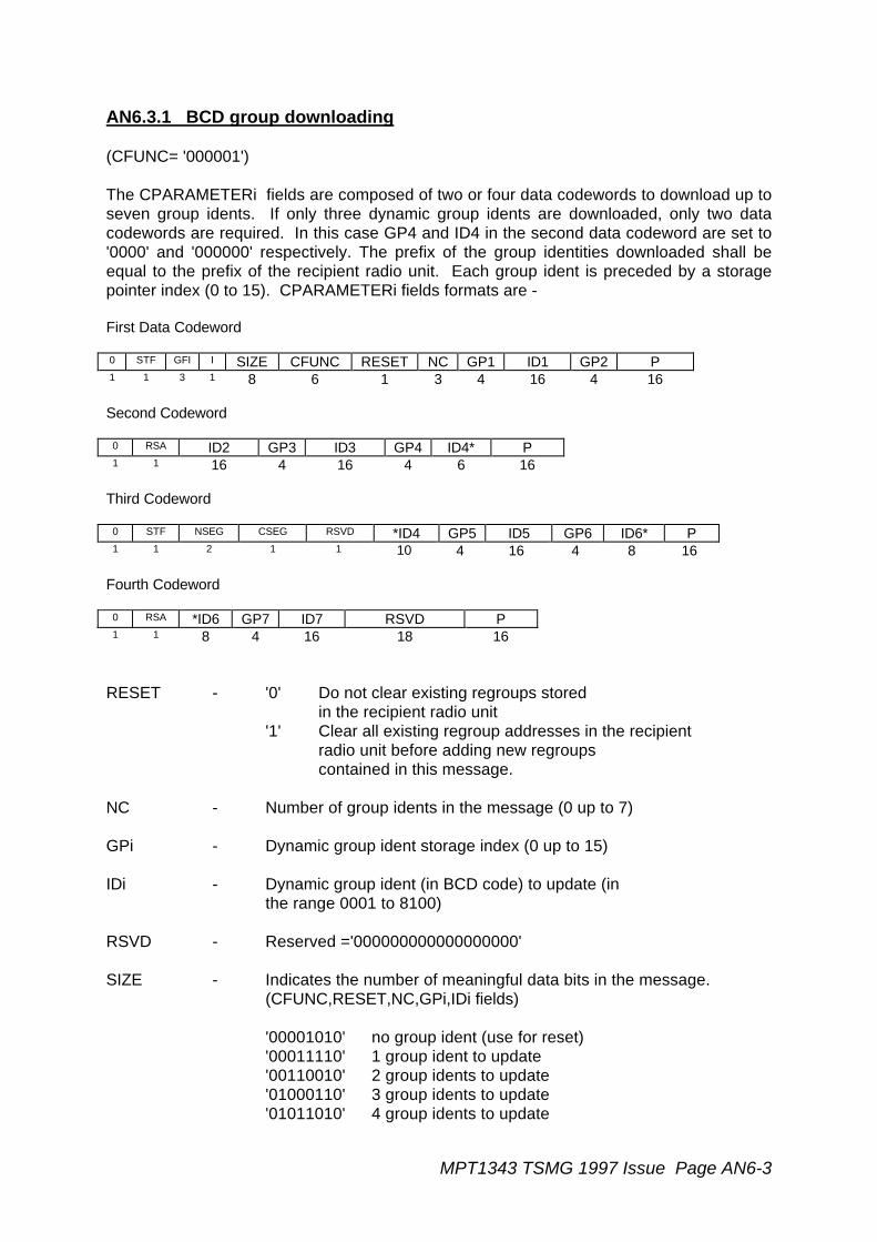
MPT1343 TSMG 1997 Issue Page AN6-3
AN6.3.1 BCD group downloading
(CFUNC= '000001')
The CPARAMETERi fields are composed of two or four data codewords to download up toseven group idents. If only three dynamic group idents are downloaded, only two datacodewords are required. In this case GP4 and ID4 in the second data codeword are set to'0000' and '000000' respectively. The prefix of the group identities downloaded shall beequal to the prefix of the recipient radio unit. Each group ident is preceded by a storagepointer index (0 to 15). CPARAMETERi fields formats are -
First Data Codeword
0 STF GFI I SIZE CFUNC RESET NC GP1 ID1 GP2 P1 1 3 1 8 6 1 3 4 16 4 16
Second Codeword
0 RSA ID2 GP3 ID3 GP4 ID4* P1 1 16 4 16 4 6 16
Third Codeword
0 STF NSEG CSEG RSVD *ID4 GP5 ID5 GP6 ID6* P1 1 2 1 1 10 4 16 4 8 16
Fourth Codeword
0 RSA *ID6 GP7 ID7 RSVD P1 1 8 4 16 18 16
RESET - '0' Do not clear existing regroups storedin the recipient radio unit
'1' Clear all existing regroup addresses in the recipientradio unit before adding new regroupscontained in this message.
NC - Number of group idents in the message (0 up to 7)
GPi - Dynamic group ident storage index (0 up to 15)
IDi - Dynamic group ident (in BCD code) to update (inthe range 0001 to 8100)
RSVD - Reserved ='000000000000000000'
SIZE - Indicates the number of meaningful data bits in the message.(CFUNC,RESET,NC,GPi,IDi fields)
'00001010' no group ident (use for reset)'00011110' 1 group ident to update'00110010' 2 group idents to update'01000110' 3 group idents to update'01011010' 4 group idents to update

Page AN6-4 MPT1343 TSMG 1997 Issue
'01101110' 5 group idents to update'10000010' 6 group idents to update'10010110' 7 group idents to update
Note :i) that all of the existing dynamic regroup idents may be cleared by transmitting
two data codewords with
- SIZE='00001010'CFUNC='00000001'RESET='1'
or
ii) that any existing single regroup identity may be deleted by transmitting a nullvalue of ident (BCD "0000")
AN6.3.2 Dynamic Regroup using Binary Format
(CFUNC = '000010' for the first block of 8 identities or CFUNC = '100010' for the secondblock of 8 identities)
The Data field is composed of two or four codewords, in order to download up to six (from 8possible index storage locations) complete group identities (PFIX+IDENT). If only threegroup identities are transmitted, only two data codewords are required. Each group ident isreferred by an index number (0 to 7) within the appropriate block. CPARAMETERi fields'formats are as following :-
First Data Codeword
0 STF GFI I SIZE CFUNC RESET NC RSVD GP1 PFIX1 IDENT1 P1 1 3 1 8 6 1 3 1 3 7 13 16
Second Codeword
0 RSA GP2 PFIX2 IDENT2 GP3 PFIX3 IDENT3 P1 1 3 7 13 3 7 13 16
Third Codeword
0 STF NSEG CSEG RSVD GP4 PFIX4 IDENT4 GP5 PFIX5 IDENT5* P1 1 2 1 1 3 7 13 3 7 9 16
Fourth Codeword
0 RSA *IDENT5 GP6 PFIX6 IDENT6 RSVD P1 1 4 3 7 13 19 16
RESET - '0' Do not clear existing regroups storedin the recipient radio unit
'1' Clear all (1st block and 2nd block) existing regroup addressesin the recipient radio unit before adding new regroupscontained in this message.
NC - Number of group addresses contained in the message (0-6)
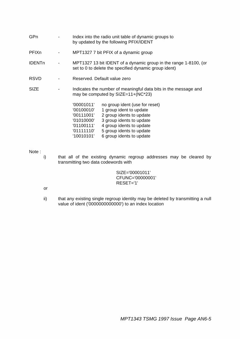
MPT1343 TSMG 1997 Issue Page AN6-5
GPn - Index into the radio unit table of dynamic groups toby updated by the following PFIX/IDENT
PFIXn - MPT1327 7 bit PFIX of a dynamic group
IDENTn - MPT1327 13 bit IDENT of a dynamic group in the range 1-8100, (orset to 0 to delete the specified dynamic group ident)
RSVD - Reserved. Default value zero
SIZE - Indicates the number of meaningful data bits in the message andmay be computed by SIZE=11+(NC*23)
'00001011' no group ident (use for reset)'00100010' 1 group ident to update'00111001' 2 group idents to update'01010000' 3 group idents to update'01100111' 4 group idents to update'01111110' 5 group idents to update'10010101' 6 group idents to update
Note :i) that all of the existing dynamic regroup addresses may be cleared by
transmitting two data codewords with
SIZE='00001011'CFUNC='00000001'RESET='1'
or
ii) that any existing single regroup identity may be deleted by transmitting a nullvalue of ident ('0000000000000') to an index location

Page AN6-6 MPT1343 TSMG 1997 Issue
AN6.3.3 Interrogate Radio Unit for Dynamic Regroup using Binary Format
(CFUNC = '000011') to interrogate the first block of 8 identities or CFUNC = '100011' tointerrogate the second block of 8 identities)
If CFUNC in the first data codeword = '000011' (pointing to the first block of 8 identities) or'100011' (pointing to the 2nd block of identities), the recipient of the SST is instructed totransmit to the sender, the particular block of dynamic regroup identities stored in itsmemory. The recipient transmits its stored regroup identities by the use of a new SingleSegment Transaction after the existing SST has been acknowledged. The format for therecipient to transmit in response to this interrogate dynamic regroups is prescribed inAN6.3.4.
Two data codewords are transmitted as follows
First Data Codeword
0 STF GFI I SIZE CFUNC RESET NC RSVD GP1 PFIX1 IDENT1 P1 1 3 1 8 6 1 3 1 3 7 13 16
Second Codeword
0 RSA GP2 PFIX2 IDENT2 GP3 PFIX3 IDENT3 P1 1 3 7 13 3 7 13 16
RESET - Not Applicable. Set to '0'
NC - Number of group addresses to interrogate from therecipient (0 up to 6)
GPn - Index pointing to the first PFIX/IDENT for the interrogation
PFIXn - Not Applicable, set to '0000000'
IDENTn - Not Applicable, set to '0000000000000'
RSVD - Reserved. Default value zero
SIZE - Indicates the number of meaningful data bits in the message'00001011' - no group ident
RSVD - Reserved
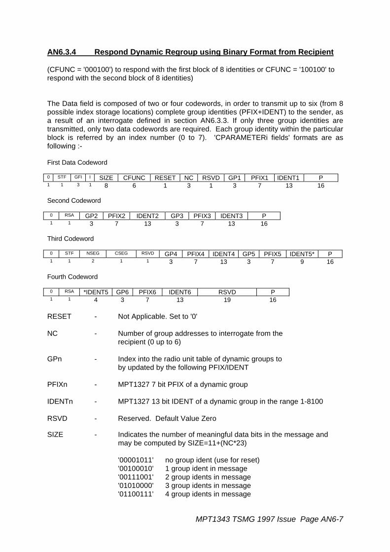
MPT1343 TSMG 1997 Issue Page AN6-7
AN6.3.4 Respond Dynamic Regroup using Binary Format from Recipient
(CFUNC = '000100') to respond with the first block of 8 identities or CFUNC = '100100' torespond with the second block of 8 identities)
The Data field is composed of two or four codewords, in order to transmit up to six (from 8possible index storage locations) complete group identities (PFIX+IDENT) to the sender, asa result of an interrogate defined in section AN6.3.3. If only three group identities aretransmitted, only two data codewords are required. Each group identity within the particularblock is referred by an index number (0 to 7). 'CPARAMETERi fields' formats are asfollowing :-
First Data Codeword
0 STF GFI I SIZE CFUNC RESET NC RSVD GP1 PFIX1 IDENT1 P1 1 3 1 8 6 1 3 1 3 7 13 16
Second Codeword
0 RSA GP2 PFIX2 IDENT2 GP3 PFIX3 IDENT3 P1 1 3 7 13 3 7 13 16
Third Codeword
0 STF NSEG CSEG RSVD GP4 PFIX4 IDENT4 GP5 PFIX5 IDENT5* P1 1 2 1 1 3 7 13 3 7 9 16
Fourth Codeword
0 RSA *IDENT5 GP6 PFIX6 IDENT6 RSVD P1 1 4 3 7 13 19 16
RESET - Not Applicable. Set to '0'
NC - Number of group addresses to interrogate from therecipient (0 up to 6)
GPn - Index into the radio unit table of dynamic groups toby updated by the following PFIX/IDENT
PFIXn - MPT1327 7 bit PFIX of a dynamic group
IDENTn - MPT1327 13 bit IDENT of a dynamic group in the range 1-8100
RSVD - Reserved. Default Value Zero
SIZE - Indicates the number of meaningful data bits in the message andmay be computed by SIZE=11+(NC*23)
'00001011' no group ident (use for reset)'00100010' 1 group ident in message'00111001' 2 group idents in message'01010000' 3 group idents in message'01100111' 4 group idents in message
Page AN6-8 MPT1343 TSMG 1997 Issue
'01111110' 5 group idents in message'10010101' 6 group idents in message
AN6.3.5 Responses for short addressing Command Messages. (GFI='110)
AN6.3.5.1 Receiving Individually Addressed HEAD message with GFI='110'
If a radio unit receives Command Message (GFI='110') then it shall respond with a suitableacknowledgement -
ACK(QUAL=0) - Unit has accepted the Command informationACKX(QUAL=0) - Unit is not equipped to accept the Command messageACKX(QUAL=1) - Unit cannot accept the Command message at this
timeACKV(QUAL=1) - Unit does not wish to accept the command
message from this calling partyACKB(QUAL=1) - Not all the appended data codewords were decodeable and the
unit requires the message to be retransmitted.
AN6.3.5.2 Responses sent to radio unit to indicate progress of short datatransaction (as requested by an RQC message):
ACK (QUAL=0) - Transaction has been successfully completed.ACKI (QUAL=1) - Intermediate acknowledgement; more signalling to follow.ACKQ (QUAL=0) - System is busy. Wait for further signalling.ACKQ (QUAL=1) - Called party engaged. Wait for further signalling.ACKX (QUAL=0) - Invalid call; message rejected.ACKX (QUAL=1) - System or called unit overload; message rejected.ACKV (QUAL=0) - Called unit not in radio contact or transaction abandoned.ACKV (QUAL=1) - Called party engaged (and TSC will not hold the request) or
called unit does not wish to accept the message.ACKT (QUAL=0) - Called party's data calls have been diverted.