mpls ldp configuration guide, cisco ios release 12 · cisco mpls ldp provides the building blocks...
TRANSCRIPT

MPLS LDP Configuration Guide, Cisco IOSRelease 12.4
Americas HeadquartersCisco Systems, Inc.170 West Tasman DriveSan Jose, CA 95134-1706USAhttp://www.cisco.comTel: 408 526-4000 800 553-NETS (6387)Fax: 408 527-0883

THE SPECIFICATIONS AND INFORMATION REGARDING THE PRODUCTS IN THIS MANUAL ARE SUBJECT TO CHANGE WITHOUT NOTICE. ALL STATEMENTS,INFORMATION, AND RECOMMENDATIONS IN THIS MANUAL ARE BELIEVED TO BE ACCURATE BUT ARE PRESENTED WITHOUT WARRANTY OF ANY KIND,EXPRESS OR IMPLIED. USERS MUST TAKE FULL RESPONSIBILITY FOR THEIR APPLICATION OF ANY PRODUCTS.
THE SOFTWARE LICENSE AND LIMITED WARRANTY FOR THE ACCOMPANYING PRODUCT ARE SET FORTH IN THE INFORMATION PACKET THAT SHIPPEDWITH THE PRODUCT AND ARE INCORPORATED HEREIN BY THIS REFERENCE. IF YOU ARE UNABLE TO LOCATE THE SOFTWARE LICENSE OR LIMITEDWARRANTY, CONTACT YOUR CISCO REPRESENTATIVE FOR A COPY.
The Cisco implementation of TCP header compression is an adaptation of a program developed by the University of California, Berkeley (UCB) as part of UCB’s public domain versionof the UNIX operating system. All rights reserved. Copyright © 1981, Regents of the University of California.
NOTWITHSTANDING ANY OTHER WARRANTY HEREIN, ALL DOCUMENT FILES AND SOFTWARE OF THESE SUPPLIERS ARE PROVIDED “AS IS” WITH ALLFAULTS. CISCO AND THE ABOVE-NAMED SUPPLIERS DISCLAIM ALL WARRANTIES, EXPRESSED OR IMPLIED, INCLUDING, WITHOUT LIMITATION, THOSE OFMERCHANTABILITY, FITNESS FOR A PARTICULAR PURPOSE AND NONINFRINGEMENT OR ARISING FROM A COURSE OF DEALING, USAGE, OR TRADEPRACTICE.
IN NO EVENT SHALL CISCO OR ITS SUPPLIERS BE LIABLE FOR ANY INDIRECT, SPECIAL, CONSEQUENTIAL, OR INCIDENTAL DAMAGES, INCLUDING,WITHOUT LIMITATION, LOST PROFITS OR LOSS OR DAMAGE TO DATA ARISING OUT OF THE USE OR INABILITY TO USE THIS MANUAL, EVEN IF CISCO ORITS SUPPLIERS HAVE BEEN ADVISED OF THE POSSIBILITY OF SUCH DAMAGES.
Cisco and the Cisco logo are trademarks or registered trademarks of Cisco and/or its affiliates in the U.S. and other countries. To view a list of Cisco trademarks, go to this URL: www.cisco.com/go/trademarks. Third-party trademarks mentioned are the property of their respective owners. The use of the word partner does not imply a partnership relationshipbetween Cisco and any other company. (1110R)
Any Internet Protocol (IP) addresses and phone numbers used in this document are not intended to be actual addresses and phone numbers. Any examples, command display output,network topology diagrams, and other figures included in the document are shown for illustrative purposes only. Any use of actual IP addresses or phone numbers in illustrative contentis unintentional and coincidental.
© 2011 Cisco Systems, Inc. All rights reserved.

C O N T E N T S
MPLS Label Distribution Protocol (LDP) 1
Finding Feature Information 1
Prerequisites for MPLS LDP 1
Information About MPLS LDP 1
Introduction to MPLS LDP 2
MPLS LDP Functional Overview 2
LDP and TDP Support 2
Introduction to LDP Sessions 3
Directly Connected MPLS LDP Sessions 3
Nondirectly Connected MPLS LDP Sessions 4
Introduction to LDP Label Bindings Label Spaces and LDP Identifiers 4
How to Configure MPLS LDP 5
Enabling Directly Connected LDP Sessions 6
Establishing Nondirectly Connected MPLS LDP Sessions 8
Saving Configurations MPLS Tag Switching Commands 11
Specifying the LDP Router ID 12
Preserving QoS Settings with MPLS LDP Explicit Null 14
Protecting Data Between LDP Peers with MD5 Authentication 18
MPLS LDP Configuration Examples 21
Configuring Directly Connected MPLS LDP Sessions Example 21
Establishing Nondirectly Connected MPLS LDP Sessions Example 23
Additional References 25
Feature Information for MPLS Label Distribution Protocol 26
MPLS LDP Session Protection 31
Finding Feature Information 31
Restrictions for MPLS LDP Session Protection 31
Information About MPLS LDP Session Protection 31
MPLS LDP Session Protection Customizations 32
How to Configure MPLS LDP Session Protection 33
MPLS LDP Configuration Guide, Cisco IOS Release 12.4 iii

Enabling MPLS LDP Session Protection 33
Verifying MPLS LDP Session Protection 35
Troubleshooting Tips 36
Configuration Examples for MPLS LDP Session Protection 36
Additional References 39
Command Reference 40
MPLS LDP Inbound Label Binding Filtering 41
Finding Feature Information 41
Restrictions 41
Information about MPLS LDP Inbound Label Binding Filtering 41
How to Configure MPLS LDP Inbound Label Binding Filtering 42
Configuring MPLS LDP Inbound Label Binding Filtering 42
Verifying that MPLS LDP Inbound Label Bindings are Filtered 44
Configuration Examples for MPLS LDP Inbound Label Binding Filtering 45
Additional References 46
Feature Information for MPLS LDP Inbound Label Binding Filtering Feature 47
Glossary 48
MPLS LDP Autoconfiguration 51
Finding Feature Information 51
Restrictions for MPLS LDP Autoconfiguration 51
Information About MPLS LDP Autoconfiguration 52
MPLS LDP Autoconfiguration on OSPF and IS-IS Interfaces 52
How to Configure MPLS LDP Autoconfiguration 52
Configuring MPLS LDP Autoconfiguration with OSPF Interfaces 52
Disabling MPLS LDP Autoconfiguration from Selected OSPF Interfaces 54
Verifying MPLS LDP Autoconfiguration with OSPF 55
Configuring MPLS LDP Autoconfiguration with IS-IS Interfaces 57
Disabling MPLS LDP Autoconfiguration from Selected IS-IS Interfaces 59
Verifying MPLS LDP Autoconfiguration with IS-IS 60
Troubleshooting Tips 61
Configuration Examples for MPLS LDP Autoconfiguration 61
MPLS LDP Autoconfiguration with OSPF Example 61
MPLS LDP Autoconfiguration with IS-IS Examples 62
Additional References 62
Feature Information for MPLS LDP Autoconfiguration 63
Contents
MPLS LDP Configuration Guide, Cisco IOS Release 12.4iv

MPLS LDP Graceful Restart 65
Finding Feature Information 65
Restrictions 65
Information About MPLS LDP Graceful Restart 66
How MPLS LDP Graceful Restart Works 66
How a Route Processor Advertises That It Supports MPLS LDP Graceful Restart 67
What Happens If a Route Processor Does Not Have LDP Graceful Restart 67
How to Configure MPLS LDP Graceful Restart 67
Configuring MPLS LDP Graceful Restart 67
Verifying the Configuration 69
Configuration Example for MPLS LDP Graceful Restart 69
Additional References 72
Feature Information for MPLS LDP Graceful Restart 73
Contents
MPLS LDP Configuration Guide, Cisco IOS Release 12.4 v

Contents
MPLS LDP Configuration Guide, Cisco IOS Release 12.4vi

MPLS Label Distribution Protocol (LDP)
Multiprotocol Label Switching (MPLS) Label Distribution Protocol (LDP) enables peer label switchrouters (LSRs) in an MPLS network to exchange label binding information for supporting hop-by-hopforwarding in an MPLS network. This module explains the concepts related to MPLS LDP and describeshow to configure MPLS LDP in a network.
• Finding Feature Information, page 1• Prerequisites for MPLS LDP, page 1• Information About MPLS LDP, page 1• How to Configure MPLS LDP, page 5• MPLS LDP Configuration Examples, page 21• Additional References, page 25• Feature Information for MPLS Label Distribution Protocol, page 26
Finding Feature InformationYour software release may not support all the features documented in this module. For the latest featureinformation and caveats, see the release notes for your platform and software release. To find informationabout the features documented in this module, and to see a list of the releases in which each feature issupported, see the Feature Information Table at the end of this document.
Use Cisco Feature Navigator to find information about platform support and Cisco software image support.To access Cisco Feature Navigator, go to www.cisco.com/go/cfn. An account on Cisco.com is not required.
Prerequisites for MPLS LDPLabel switching on a router requires that Cisco Express Forwarding (CEF) be enabled on that router.
Information About MPLS LDP• Introduction to MPLS LDP, page 2
• MPLS LDP Functional Overview, page 2
• LDP and TDP Support, page 2
• Introduction to LDP Sessions, page 3
• Introduction to LDP Label Bindings Label Spaces and LDP Identifiers, page 4
MPLS LDP Configuration Guide, Cisco IOS Release 12.4 1

Introduction to MPLS LDPMPLS LDP provides the means for LSRs to request, distribute, and release label prefix binding informationto peer routers in a network. LDP enables LSRs to discover potential peers and to establish LDP sessionswith those peers for the purpose of exchanging label binding information.
MPLS LDP enables one LSR to inform another LSR of the label bindings it has made. Once a pair ofrouters communicate the LDP parameters, they establish a label-switched path (LSP). MPLS LDP enablesLSRs to distribute labels along normally routed paths to support MPLS forwarding. This method of labeldistribution is also called hop-by-hop forwarding. With IP forwarding, when a packet arrives at a router therouter looks at the destination address in the IP header, performs a route lookup, and forwards the packet tothe next hop. With MPLS forwarding, when a packet arrives at a router the router looks at the incominglabel, looks up the label in a table, and then forwards the packet to the next hop. MPLS LDP is useful forapplications that require hop-by-hop forwarding, such as MPLS VPNs.
MPLS LDP Functional OverviewCisco MPLS LDP provides the building blocks for MPLS-enabled applications, such as MPS VirtualPrivate Networks (VPNs).
LDP provides a standard methodology for hop-by-hop, or dynamic label, distribution in an MPLS networkby assigning labels to routes that have been chosen by the underlying Interior Gateway Protocol (IGP)routing protocols. The resulting labeled paths, called label switch paths (LSPs), forward label traffic acrossan MPLS backbone to particular destinations. These capabilities enable service providers to implementMPLS-based IP VPNs and IP+ATM services across multivendor MPLS networks.
LDP and TDP SupportLDP supercedes Tag Distribution Protocol (TDP). See the table below for information about LDP and TDPsupport in Cisco IOS releases.
Use caution when upgrading the image on a router that uses TDP. Ensure that the TDP sessions areestablished when the new image is loaded. You can accomplish this by issuing the global configurationcommand mpls label protocol tdp. Issue this command and save it to the startup configuration beforeloading the new image. Alternatively, you can enter the command and save the running configurationimmediately after loading the new image.
Table 1 LDP and TDP Support
Train and Release LDP/TDP Support
12.0S Train • TDP is enabled by default.• Cisco IOS Release 12.0(29)S and earlier releases: TDP is
supported for LDP features.• Cisco IOS Release 12.0(30)S and later releases: TDP is
not support for LDP features.
Introduction to MPLS LDP Information About MPLS LDP
MPLS LDP Configuration Guide, Cisco IOS Release 12.42

Train and Release LDP/TDP Support
12.2S, SB, and SR Trains • LDP is enabled by default.• Cisco IOS Release 12.2(25)S and earlier releases: TDP is
supported for LDP features.• Cisco IOS Releases 12.2(27)SBA, 12.2(27)SRA,
12.2(27)SRB and later releases: TDP is not supported forLDP features.
12.T/Mainline Trains • Cisco IOS Release 12.3(14)T and earlier releases: TDP isenabled by default.
• Cisco IOS Releases 12.4 and 12.4T and later releases:LDP is enabled by default.
• Cisco IOS Release 12.3(11)T and earlier releases: TDP issupported for LDP features.
• Cisco IOS Release 12.3(14)T and later releases: TDP isnot support ed for LDP features.
Introduction to LDP SessionsWhen you enable MPLS LDP, the LSRs send out messages to try to find other LSRs with which they cancreate LDP sessions. The following sections explain the differences between directly connected LDPsessions and nondirectly connected LDP sessions.
• Directly Connected MPLS LDP Sessions, page 3
• Nondirectly Connected MPLS LDP Sessions, page 4
Directly Connected MPLS LDP SessionsIf an LSR is one hop from its neighbor, it is directly connected to its neighbor. The LSR sends out LDP linkHello messages as User Datagram Protocol (UDP) packets to all the routers on the subnet (multicast). Aneighboring LSR may respond to the link Hello message, allowing the two routers to establish an LDPsession. This is called basic discovery.
To initiate an LDP session between routers, the routers determine which router will take the active role andwhich router will take the passive role. The router that takes the active role establishes the LDP TCPconnection session and initiates the negotiation of the LDP session parameters. To determine the roles, thetwo routers compare their transport addresses. The router with the higher IP address takes the active roleand establishes the session.
After the LDP TCP connection session is established, the LSRs negotiate the session parameters, includingthe method of label distribution to be used. Two methods are available:
• Downstream Unsolicited: An LSR advertises label mappings to peers without being asked to.• Downstream on Demand: An LSR advertises label mappings to a peer only when the peer asks for
them.
For information about creating LDP sessions, see the Enabling Directly Connected LDP Sessions, page6.
Introduction to LDP SessionsDirectly Connected MPLS LDP Sessions
MPLS LDP Configuration Guide, Cisco IOS Release 12.4 3

Nondirectly Connected MPLS LDP SessionsIf the LSR is more than one hop from its neighbor, it is nondirectly connected to its neighbor. For thesenondirectly connected neighbors, the LSR sends out a targeted Hello message as a UDP packet, but as aunicast message specifically addressed to that LSR. The nondirectly connected LSR responds to the Hellomessage and the two routers begin to establish an LDP session. This is called extended discovery.
An MPLS LDP targeted session is a label distribution session between routers that are not directlyconnected. When you create an MPLS traffic engineering tunnel interface, you need to establish a labeldistribution session between the tunnel headend and the tailend routers. You establish nondirectlyconnected MPLS LDP sessions by enabling the transmission of targeted Hello messages.
You can use the mpls ldp neighbor targetedcommand to set up a targeted session when other means ofestablishing targeted sessions do not apply, such as configuring mpls ipon a traffic engineering (TE) tunnelor configuring Any Transport over MPLS (AToM) virtual circuits (VCs). For example, you can use thiscommand to create a targeted session between directly connected MPLS label switch routers (LSRs) whenMPLS label forwarding convergence time is an issue.
The mpls ldp neighbor targetedcommand can improve label convergence time for directly connectedneighbor LSRs when the link(s) directly connecting them are down. When the links between the neighborLSRs are up, both the link and targeted Hellos maintain the LDP session. If the links between the neighborLSRs go down, the targeted Hellos maintain the session, allowing the LSRs to retain labels learned fromeach other. When a link directly connecting the LSRs comes back up, the LSRs can immediately reinstalllabels for forwarding use without having to reestablish their LDP session and exchange labels.
The exchange of targeted Hello messages between two nondirectly connected neighbors can occur inseveral ways, including the following:
• Router 1 sends targeted Hello messages carrying a response request to Router 2. Router 2 sendstargeted Hello messages in response if its configuration permits. In this situation, Router 1 isconsidered to be active and Router 2 is considered to be passive.
• Router 1 and Router 2 both send targeted Hello messages to each other. Both routers are considered tobe active. Both, one, or neither router can also be passive, if they have been configured to respond torequests for targeted Hello messages from each other.
The default behavior of an LSR is to ignore requests from other LSRs that send targeted Hello messages.You can configure an LSR to respond to requests for targeted Hello messages by issuing the mpls ldpdiscovery targeted-hello accept command.
The active LSR mandates the protocol that is used for a targeted session. The passive LSR uses the protocolof the received targeted Hello messages.
For information about creating MPLS LDP targeted sessions, see the Establishing Nondirectly ConnectedMPLS LDP Sessions, page 8.
Introduction to LDP Label Bindings Label Spaces and LDP IdentifiersAn LDP label binding is an association between a destination prefix and a label. The label used in a labelbinding is allocated from a set of possible labels called a label space.
LDP supports two types of label spaces:
• Interface-specific--An interface-specific label space uses interface resources for labels. For example,label-controlled ATM (LC-ATM) interfaces use virtual path identifiers/virtual circuit identifiers (VPIs/VCIs) for labels. Depending on its configuration, an LDP platform may support zero, one, or moreinterface-specific label spaces.
Introduction to LDP Label Bindings Label Spaces and LDP Identifiers Nondirectly Connected MPLS LDP Sessions
MPLS LDP Configuration Guide, Cisco IOS Release 12.44

• Platform-wide--An LDP platform supports a single platform-wide label space for use by interfaces thatcan share the same labels. For Cisco platforms, all interface types, except LC-ATM, use the platform-wide label space.
LDP uses a 6-byte quantity called an LDP Identifier (or LDP ID) to name label spaces. The LDP ID ismade up of the following components:
• The first four bytes, called the LPD router ID, identify the LSR that owns the label space.• The last two bytes, called the local label space ID, identify the label space within the LSR. For the
platform-wide label space, the last two bytes of the LDP ID are always both 0.
The LDP ID takes the following form:
<LDP router ID> : <local label space ID>
The following are examples of LPD IDs:
• 172.16.0.0:0• 192.168.0.0:3
The router determines the LDP router ID as follows, if the mpls ldp router-id command is not executed,
1 The router examines the IP addresses of all operational interfaces.2 If these IP addresses include loopback interface addresses, the router selects the largest loopback
address as the LDP router ID.3 Otherwise, the router selects the largest IP address pertaining to an operational interface as the LDP
router ID.
The normal (default) method for determining the LDP router ID may result in a router ID that is not usablein certain situations. For example, the router might select an IP address as the LDP router ID that therouting protocol cannot advertise to a neighboring router. The mpls ldp router-id command allows you tospecify the IP address of an interface as the LDP router ID. Make sure the specified interface is operationalso that its IP address can be used as the LDP router ID.
When you issue the mpls ldp router-id command without the force keyword, the router select selects theIP address of the specified interface (provided that the interface is operational) the next time it is necessaryto select an LDP router ID, which is typically the next time the interface is shut down or the address isconfigured.
When you issue the mpls ldp router-idcommand with the force keyword, the effect of the mpls ldprouter-idcommand depends on the current state of the specified interface:
• If the interface is up (operational) and if its IP address is not currently the LDP router ID, the LDProuter ID changes to the IP address of the interface. This forced change in the LDP router ID tearsdown any existing LDP sessions, releases label bindings learned via the LDP sessions, and interruptsMPLS forwarding activity associated with the bindings.
• If the interface is down (not operational) when the mpls ldp router-idinterface force command isissued, when the interface transitions to up, the LDP router ID changes to the IP address of theinterface. This forced change in the LDP router ID tears down any existing LDP sessions, releaseslabel bindings learned via the LDP sessions, and interrupts MPLS forwarding activity associated withthe bindings.
How to Configure MPLS LDP• Enabling Directly Connected LDP Sessions, page 6
MPLS Label Distribution Protocol (LDP)How to Configure MPLS LDP
MPLS LDP Configuration Guide, Cisco IOS Release 12.4 5
• Establishing Nondirectly Connected MPLS LDP Sessions, page 8
• Saving Configurations MPLS Tag Switching Commands, page 11
• Specifying the LDP Router ID, page 12
• Preserving QoS Settings with MPLS LDP Explicit Null, page 14
• Protecting Data Between LDP Peers with MD5 Authentication, page 18
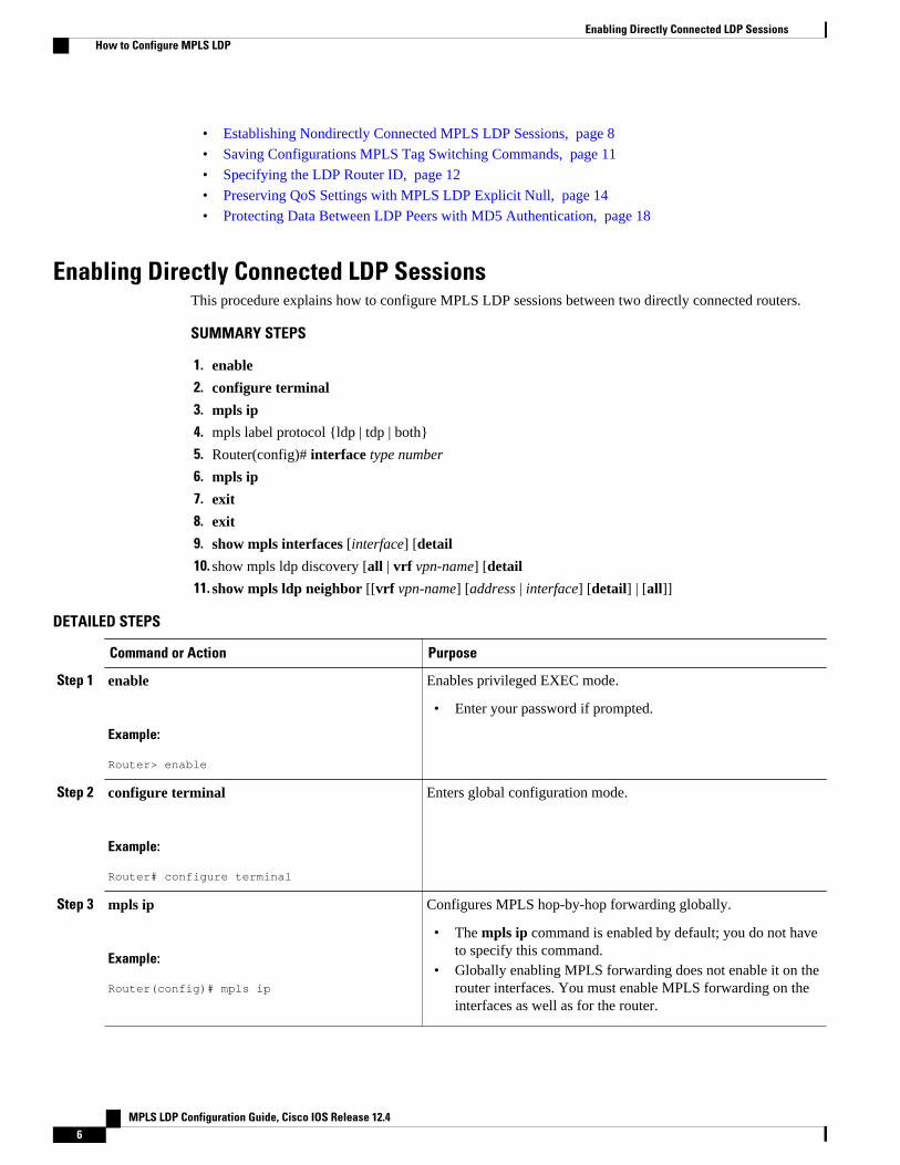
Enabling Directly Connected LDP SessionsThis procedure explains how to configure MPLS LDP sessions between two directly connected routers.
SUMMARY STEPS
1. enable
2. configure terminal
3. mpls ip
4. mpls label protocol {ldp | tdp | both}
5. Router(config)# interface type number
6. mpls ip
7. exit
8. exit
9. show mpls interfaces [interface] [detail
10. show mpls ldp discovery [all | vrf vpn-name] [detail
11. show mpls ldp neighbor [[vrf vpn-name] [address | interface] [detail] | [all]]
DETAILED STEPS
Command or Action Purpose
Step 1 enable
Example:
Router> enable
Enables privileged EXEC mode.
• Enter your password if prompted.
Step 2 configure terminal
Example:
Router# configure terminal
Enters global configuration mode.
Step 3 mpls ip
Example:
Router(config)# mpls ip
Configures MPLS hop-by-hop forwarding globally.
• The mpls ip command is enabled by default; you do not haveto specify this command.
• Globally enabling MPLS forwarding does not enable it on therouter interfaces. You must enable MPLS forwarding on theinterfaces as well as for the router.
Enabling Directly Connected LDP Sessions How to Configure MPLS LDP
MPLS LDP Configuration Guide, Cisco IOS Release 12.46

Command or Action Purpose
Step 4 mpls label protocol {ldp | tdp | both}
Example:
Router(config)# mpls label protocol ldp
Configures the use of LDP on all interfaces. LDP is the default.
• If you set all interfaces globally to LDP, you can overridespecific interfaces with either the tdp or both keyword byspecifying the command in interface configuration mode.
Step 5 Router(config)# interface type number
Example:
Router(config)# interface ethernet3/0
Specifies the interface to be configured and enters interfaceconfiguration mode.
Step 6 mpls ip
Example:
Router(config-if)# mpls ip
Configures MPLS hop-by-hop forwarding on the interface.
• You must enable MPLS forwarding on the interfaces as wellas for the router.
Step 7 exit
Example:
Router(config-if)# exit
Exits interface configuration mode and enters global configurationmode.
Step 8 exit
Example:
Router(config)# exit
Exits global configuration mode and enters privileged EXECmode.
Step 9 show mpls interfaces [interface] [detail
Example:
Router# show mpls interfaces
Verifies that the interfaces have been configured to use LDP, TDP,or both.
Step 10 show mpls ldp discovery [all | vrf vpn-name] [detail
Example:
Router# show mpls ldp discovery
Verifies that the interface is up and is sending Discovery Hellomessages.
MPLS Label Distribution Protocol (LDP)How to Configure MPLS LDP
MPLS LDP Configuration Guide, Cisco IOS Release 12.4 7

Command or Action Purpose
Step 11 show mpls ldp neighbor [[vrf vpn-name] [address |interface] [detail] | [all]]
Example:
Router# show mpls ldp neighbor
Displays the status of LDP sessions.
Examples
The following show mpls interfaces command verifies that interfaces Ethernet 1/0 and 1/1 have beenconfigured to use LDP:
Router# show mpls interfacesInterface IP Tunnel BGP Static OperationalEthernet3/0 Yes (ldp) No No No Yes Ethernet3/1 Yes No No No Yes
The following show mpls ldp discovery command verifies that the interface is up and is sending LDPDiscovery Hello messages (as opposed to TDP Hello messages):
Router# show mpls ldp discoveryLocal LDP Identifier: 172.16.12.1:0 Discovery Sources: Interfaces: Ethernet3/0 (ldp): xmit
The following example shows that the LDP session between routers was successfully established:
Router# show mpls ldp neighborPeer LDP Ident: 10.1.1.2:0; Local LDP Ident 10.1.1.1:0TCP connection: 10.1.1.2.18 - 10.1.1.1.66State: Oper; Msgs sent/rcvd: 12/11; DownstreamUp time: 00:00:10LDP discovery sources:FastEthernet1/0, Src IP addr: 10.20.10.2Addresses bound to peer LDP Ident:10.1.1.2 10.20.20.1 10.20.10.2
For examples on configuring directly connected LDP sessions, see the Configuring Directly ConnectedMPLS LDP Sessions Example, page 21.
Establishing Nondirectly Connected MPLS LDP SessionsThis section explains how to configure nondirectly connected MPLS LDP sessions, which enable you toestablish an LDP session between routers that are not directly connected.
• MPLS requires CEF.• You must configure the routers at both ends of the tunnel to be active or enable one router to be
passive with the mpls ldp discovery targeted-hello accept command.
Establishing Nondirectly Connected MPLS LDP Sessions How to Configure MPLS LDP
MPLS LDP Configuration Guide, Cisco IOS Release 12.48

SUMMARY STEPS
1. enable
2. configure terminal
3. mpls ip
4. mpls label protocol {ldp | tdp | both}
5. interface tunnelnumber
6. tunnel destination ip-address
7. mpls ip
8. exit
9. exit
10. show mpls ldp discovery [all | vrf vpn-name] [detail
DETAILED STEPS
Command or Action Purpose
Step 1 enable
Example:
Router> enable
Enables privileged EXEC mode.
• Enter your password if prompted.
Step 2 configure terminal
Example:
Router# configure terminal
Enters global configuration mode.
Step 3 mpls ip
Example:
Router(config)# mpls ip
Configures MPLS hop-by-hop forwarding globally.
• The mpls ip command is enabled by default; you do not have tospecify this command.
• Globally enabling MPLS forwarding does not enable it on therouter interfaces. You must enable MPLS forwarding on theinterfaces as well as for the router.
Step 4 mpls label protocol {ldp | tdp | both}
Example:
Router(config)# mpls label protocol ldp
Configures the use of LDP on all interfaces. LDP is the default.
• If you set all interfaces globally to LDP, you can overridespecific interfaces with either the tdp or both keyword byspecifying the command in interface configuration mode.
MPLS Label Distribution Protocol (LDP)How to Configure MPLS LDP
MPLS LDP Configuration Guide, Cisco IOS Release 12.4 9

Command or Action Purpose
Step 5 interface tunnelnumber
Example:
Router(config)# interface tunnel1
Configures a tunnel interface and enters interface configurationmode.
Step 6 tunnel destination ip-address
Example:
Router(config-if)# tunnel destination 172.16.1.1
Assigns an IP address to the tunnel interface.
Step 7 mpls ip
Example:
Router(config-if)# mpls ip
Configures MPLS hop-by-hop forwarding on the interface.
• You must enable MPLS forwarding on the interfaces as well asfor the router.
Step 8 exit
Example:
Router(config-if)# exit
Exits interface configuration mode and enters global configurationmode.
Step 9 exit
Example:
Router(config)# exit
Exits global configuration mode and enters privileged EXEC mode.
Step 10 show mpls ldp discovery [all | vrf vpn-name][detail
Example:
Router# show mpls ldp discovery
Verifies that the interface is up and is sending Discovery Hellomessages.
Example
The following example shows the output of the show mpls ldp discovery command for a nondirectlyconnected LDP session.
Router# show mpls ldp discoveryLocal LDP Identifier: 172.16.0.0:0Discovery Sources:
MPLS Label Distribution Protocol (LDP) How to Configure MPLS LDP
MPLS LDP Configuration Guide, Cisco IOS Release 12.410

Interfaces:POS2/0 (ldp): xmit/recvLDP Id: 172.31.255.255:0Tunnel1 (ldp): Targeted -> 192.168.255.255Targeted Hellos:172.16.0.0 -> 192.168.255.255 (ldp): active, xmit/recvLDP Id: 192.168.255.255:0172.16.0.0 -> 192.168.0.0 (tdp): passive, xmit/recvTDP Id: 192.168.0.0:0
This command output indicates that:
• The local LSR (172.16.0.0) sent LDP link Hello messages on interface POS2/0 and discoveredneighbor 172.31.255.255.
• The local LSR sent LDP targeted Hello messages associated with interface Tunnel1 to target192.168.255.255. The LSR was configured to use LDP.
• The local LSR is active for targeted discovery activity with 192.168.255.255; this means that thetargeted Hello messages it sends to 192.168.255.255 carry a response request. The local LSR wasconfigured to have an LDP session with the nondirectly connected LSR 192.168.255.255.
• The local LSR is not passive from the discovery activity with 192.168.255.255 for one of thefollowing reasons:
◦ The targeted Hello messages it receives from 192.168.255.255 do not carry a response request.◦ The local LSR has not been configured to respond to such requests.
• The local LSR sent TDP directed Hello messages to the target LSR 192.168.0.0. This LSR uses TDPbecause the Hello messages received from the target LSR 192.168.0.0 were TDP directed Hellomessages.
• The local LSR is passive in discovery activity with LSR 192.168.0.0. This means that the directedHello messages it receives from LSR 192.168.0.0 carry a response request and that the local LSR hasbeen configured with the mpls ldp discovery targeted-hello accept command to respond to suchrequests from LSR 192.168.0.0.
• The local LSR is not active in discovery activity with LSR 192.168.0.0, because no application thatrequires an LDP session with LSR 192.168.0.0 has been configured on the local LSR.
For examples of configuring LDP targeted sessions, see the Establishing Nondirectly Connected MPLSLDP Sessions Example, page 23.
Saving Configurations MPLS Tag Switching CommandsIn releases of Cisco IOS software prior to 12.4(2)T, some MPLS commands had both a tag-switchingversion and an MPLS version. For example, the two commands tag-switching ip and mpls ip were thesame. To support backward compatibility, the tag-switching form of the command was written to the savedconfiguration.
Starting in Cisco IOS Release 12.4(2)T, the MPLS form of the command is written to the savedconfiguration.
For example, if an ATM interface is configured using the following commands, which have both a tag-switching form and an MPLS form:
Router(config)# interface ATM3/0 Router(config-if)# ip unnumbered Loopback0router(config-if)# tag-switching ipRouter(config-if)# mpls label protocol ldp
After you enter these commands and save this configuration or display the running configuration with theshow runningcommand, the commands saved or displayed appear as follows:
interface ATM3/0
Saving Configurations MPLS Tag Switching CommandsHow to Configure MPLS LDP
MPLS LDP Configuration Guide, Cisco IOS Release 12.4 11

ip unnumbered Loopback0mpls ipmpls label protocol ldp
Specifying the LDP Router IDThe mpls ldp router-id command allows you to establish the IP address of an interface as the LDP routerID.
The following steps describe the normal process for determining the LDP router ID:
1 The router considers all the IP addresses of all operational interfaces.2 If these addresses include loopback interface addresses, the router selects the largest loopback address.
Configuring a loopback address helps ensure a stable LDP ID for the router, because the state ofloopback addresses does not change. However, configuring a loopback interface and IP address on eachrouter is not required.
The loopback IP address does not become the router ID of the local LDP ID under the followingcircumstances:
• ◦ If the loopback interface has been explicitly shut down.◦ If the mpls ldp router-id command specifies that a different interface should be used as the LDP
router ID.
If you use a loopback interface, make sure that the IP address for the loopback interface is configured witha /32 network mask. In addition, make sure that the routing protocol in use is configured to advertise thecorresponding /32 network.
1 Otherwise, the router selects the largest interface address.
The router might select a router ID that is not usable in certain situations. For example, the router mightselect an IP address that the routing protocol cannot advertise to a neighboring router.
The router implements the router ID the next time it is necessary to select an LDP router ID. The effect ofthe command is delayed until the next time it is necessary to select an LDP router ID, which is typically thenext time the interface is shut down or the address is deconfigured.
If you use the force keyword with the mpls ldp router-id command, the router ID takes effect morequickly. However, implementing the router ID depends on the current state of the specified interface:
• If the interface is up (operational) and its IP address is not currently the LDP router ID, the LDP routerID is forcibly changed to the IP address of the interface. This forced change in the LDP router ID tearsdown any existing LDP sessions, releases label bindings learned via the LDP sessions, and interruptsMPLS forwarding activity associated with the bindings.
• If the interface is down, the LDP router ID is forcibly changed to the IP address of the interface whenthe interface transitions to up. This forced change in the LDP router ID tears down any existing LDPsessions, releases label bindings learned via the LDP sessions, and interrupts MPLS forwardingactivity associated with the bindings.
Make sure the specified interface is operational before assigning it as the LDP router ID.
Specifying the LDP Router ID How to Configure MPLS LDP
MPLS LDP Configuration Guide, Cisco IOS Release 12.412

SUMMARY STEPS
1. enable
2. configure terminal
3. mpls ip
4. mpls label protocol {ldp | tdp | both}
5. mpls ldp router-id interface [force]
6. exit
7. show mpls ldp discovery [all | detail |vrf vpn-name]
DETAILED STEPS
Command or Action Purpose
Step 1 enable
Example:
Router> enable
Enables privileged EXEC mode.
• Enter your password if prompted.
Step 2 configure terminal
Example:
Router# configure terminal
Enters global configuration mode.
Step 3 mpls ip
Example:
Router(config)# mpls ip
Configures MPLS hop-by-hop forwarding globally.
• The mpls ip command is enabled by default; you do not haveto specify this command.
• Globally enabling MPLS forwarding does not enable it on therouter interfaces. You must enable MPLS forwarding on theinterfaces as well as for the router.
Step 4 mpls label protocol {ldp | tdp | both}
Example:
Router(config)# mpls label protocol ldp
Configures the use of LDP on all interfaces. LDP is the default.
• If you set all interfaces globally to LDP, you can overridespecific interfaces with either the tdp or both keyword byspecifying the command in interface configuration mode.
Step 5 mpls ldp router-id interface [force]
Example:
Router(config)# mpls ldp router-id pos2/0/0
Specifies the preferred interface for determining the LDP router ID.
MPLS Label Distribution Protocol (LDP)How to Configure MPLS LDP
MPLS LDP Configuration Guide, Cisco IOS Release 12.4 13

Command or Action Purpose
Step 6 exit
Example:
Router(config)# exit
Exits global configuration mode and enters privileged EXEC mode.
Step 7 show mpls ldp discovery [all | detail |vrf vpn-name]
Example:
Router# show mpls ldp discovery
Displays the LDP identifier for the local router.
Example
The following example assigns interface pos2/0/0 as the LDP router ID:
Router> enableRouter# configure terminalRouter(config)# mpls ipRouter(config)# mpls label protocol ldpRouter(config)# mpls ldp router-id pos2/0/0 force
The following example displays the LDP router ID (10.15.15.15):
Router# show mpls ldp discovery Local LDP Identifier: 10.15.15.15:0Discovery Sources: Interfaces: Ethernet4 (ldp): xmit/recv LDP Id: 10.14.14.14:0
Preserving QoS Settings with MPLS LDP Explicit NullNormally, LDP advertises an Implicit Null label for directly connected routes. The Implicit Null labelcauses the second last (penultimate) label switched router (LSR) to remove the MPLS header from thepacket. In this case, the penultimate LSR and the last LSR do not have access to the quality of service(QoS) values that the packet carried before the MPLS header was removed. To preserve the QoS values,you can configure the LSR to advertise an explicit NULL label (a label value of zero). The LSR at thepenultimate hop forwards MPLS packets with a NULL label instead of forwarding IP packets.
Note An explicit NULL label is not needed when the penultimate hop receives MPLS packets with a label stackthat contains at least two labels and penultimate hop popping is performed. In that case, the inner label canstill carry the QoS value needed by the penultimate and edge LSR to implement their QoS policy.
When you issue the mpls ldp explicit-null command, Explicit Null is advertised in place of Implicit Nullfor directly connected prefixes.
Preserving QoS Settings with MPLS LDP Explicit Null How to Configure MPLS LDP
MPLS LDP Configuration Guide, Cisco IOS Release 12.414

SUMMARY STEPS
1. enable
2. configure terminal
3. mpls ip
4. mpls label protocol {ldp | tdp | both}
5. interface type number
6. mpls ip
7. exit
8. mpls ldp explicit-null [for prefix-acl | to peer-acl | for prefix-acl to peer-acl]
9. exit
10. show mpls forwarding-table [network {mask | length} | labels label [- label] | interface interface |next-hop address | lsp-tunnel[tunnel-id]] [vrf vpn-name] [detail]
DETAILED STEPS
Command or Action Purpose
Step 1 enable
Example:
Router> enable
Enables privileged EXEC mode.
• Enter your password if prompted.
Step 2 configure terminal
Example:
Router# configure terminal
Enters global configuration mode.
Step 3 mpls ip
Example:
Router(config)# mpls ip
Configures MPLS hop-by-hop forwarding globally.
• The mpls ip command is enabled by default; you do nothave to specify this command.
• Globally enabling MPLS forwarding does not enable it onthe router interfaces. You must enable MPLS forwarding onthe interfaces as well as for the router.
Step 4 mpls label protocol {ldp | tdp | both}
Example:
Router(config)# mpls label protocol ldp
Configures the use of LDP on all interfaces. LDP is the default.
• If you set all interfaces globally to LDP, you can overridespecific interfaces with either the tdp or both keyword byspecifying the command in interface configuration mode.
MPLS Label Distribution Protocol (LDP)How to Configure MPLS LDP
MPLS LDP Configuration Guide, Cisco IOS Release 12.4 15

Command or Action Purpose
Step 5 interface type number
Example:
Router(config)# interface atm2/0
Specifies the interface to be configured and enters interfaceconfiguration mode.
Step 6 mpls ip
Example:
Router(config-if)# mpls ip
Configures MPLS hop-by-hop forwarding on the interface.
• You must enable MPLS forwarding on the interfaces as wellas for the router.
Step 7 exit
Example:
Router(config-if)# exit
Exits interface configuration mode and enters globalconfiguration mode.
Step 8 mpls ldp explicit-null [for prefix-acl | to peer-acl |for prefix-acl to peer-acl]
Example:
Router(config)# mpls ldp explicit-null
Advertises an Explicit Null label in situations where it wouldnormally advertise an Implicit Null label.
Step 9 exit
Example:
Router(config)# exit
Exits global configuration mode and enter privileged EXECmode.
Step 10 show mpls forwarding-table [network {mask |length} | labels label [- label] | interface interface |next-hop address | lsp-tunnel[tunnel-id]] [vrf vpn-name] [detail]
Example:
Router# show mpls forwarding-table
Verifies that MPLS packets are forwarded with an explicit-nulllabel (value of 0).
MPLS Label Distribution Protocol (LDP) How to Configure MPLS LDP
MPLS LDP Configuration Guide, Cisco IOS Release 12.416

Examples
Enabling explicit-null on an egress LSR causes that LSR to advertise the explicit-null label to all adjacentMPLS routers.
Router# configure terminalRouter(config)# mpls ldp explicit-null
If you issue the show mpls forwarding-table command on an adjacent router, the output shows that MPLSpackets are forwarded with an explicit-null label (value of 0). In the following example, the second columnshows that entries have outgoing labels of 0, where once they were marked “Pop label”.
Router# show mpls forwarding-table Local Outgoing Prefix Bytes label Outgoing Next Hoplabel label or VC or Tunnel Id switched interface19 Pop tag 10.12.12.12/32 0 Fa2/1/0 172.16.0.122 0 10.14.14.14/32 0 Fa2/0/0 192.168.0.223 0 172.24.24.24/32 0 Fa2/0/0 192.168.0.224 0 192.168.0.0/8 0 Fa2/0/0 192.168.0.225 0 10.15.15.15/32 0 Fa2/0/0 192.168.0.226 0 172.16.0.0/8 0 Fa2/0/0 192.168.0.227 25 10.16.16.16/32 0 Fa2/0/0 192.168.0.2228 0 10.34.34.34/32 0 Fa2/0/0 192.168.0.2
Enabling explicit-null and specifying the forkeyword with a standard access control list (ACL) changes alladjacent MPLS routers' tables to swap an explicit-null label for only those entries specified in the access-list. In the following example, an access-list is created that contains the 10.24.24.24/32 entry. Explicit nullis configured and the access list is specified.
Router# configure terminalRouter(config)# mpls label protocol ldpRouter(config)# access-list 24 permit host 10.24.24.24Router(config)# mpls ldp explicit-null for 24
If you issue the show mpls forwarding-table command on an adjacent router, the output shows that theonly the outgoing labels for the addresses specified (172.24.24.24/32) change from Pop label to 0. All otherPop label outgoing labels remain the same.
Router# show mpls forwarding-table Local Outgoing Prefix Bytes label Outgoing Next Hoplabel label or VC or Tunnel Id switched interface19 Pop tag 10.12.12.12/32 0 Fa2/1/0 172.16.0.122 0 10.14.14.14/32 0 Fa2/0/0 192.168.0.223 0 172.24.24.24/32 0 Fa2/0/0 192.168.0.224 0 192.168.0.0/8 0 Fa2/0/0 192.168.0.225 0 10.15.15.15/32 0 Fa2/0/0 192.168.0.226 0 172.16.0.0/8 0 Fa2/0/0 192.168.0.227 25 10.16.16.16/32 0 Fa2/0/0 192.168.0.2228 0 10.34.34.34/32 0 Fa2/0/0 192.168.0.2
Enabling explicit null and adding the to keyword and an access list enables you to advertise explicit-nulllabels to only those adjacent routers specified in the access-list.To advertise explicit-null to a particularrouter, you must specify the router's LDP ID in the access-list.
In the following example, an access-list contains the 10.15.15.15/32 entry, which is the LDP ID of anadjacent MPLS router. The router that is configured with explicit null advertises explicit-null labels only tothat adjacent router.
Router# show mpls ldp discovery Local LDP Identifier: 10.15.15.15:0Discovery Sources: Interfaces: Ethernet4 (ldp): xmit/recv TDP Id: 10.14.14.14:0
MPLS Label Distribution Protocol (LDP)How to Configure MPLS LDP
MPLS LDP Configuration Guide, Cisco IOS Release 12.4 17

Router# configure terminalRouter(config)# mpls label protocol ldpRouter(config)# access-list 15 permit host 10.15.15.15Router(config)# mpls ldp explicit-null to 15
If you issue the show mpls forwarding-table command, the output shows that explicit null labels aregoing only to the router specified in the access list.
Router# show mpls forwarding-table Local Outgoing Prefix Bytes label Outgoing Next Hoplabel label or VC or Tunnel Id switched interface19 Pop tag 10.12.12.12/32 0 Fa2/1/0 172.16.0.122 0 10.14.14.14/32 0 Fa2/0/0 192.168.0.223 0 172.24.24.24/32 0 Fa2/0/0 192.168.0.224 0 192.168.0.0/8 0 Fa2/0/0 192.168.0.225 0 10.15.15.15/32 0 Fa2/0/0 192.168.0.226 0 172.16.0.0/8 0 Fa2/0/0 192.168.0.227 25 10.16.16.16/32 0 Fa2/0/0 192.168.0.2228 0 10.34.34.34/32 0 Fa2/0/0 192.168.0.2
Enabling explicit-null with both the forand tokeywords enables you to specify which routes to advertisewith explicit-null labels and to which adjacent routers to advertise these explicit-null labels.
Router# show access 15Standard IP access list 15 permit 10.15.15.15 (7 matches)Router# show access 24Standard IP access list 24 permit 10.24.24.24 (11 matches)Router# configure terminalRouter(config)# mpls label protocol ldpRouter(config)# mpls ldp explicit-null for 24 to 15
If you issue the show mpls forwarding-table command on the router called 47K-60-4, the output showsthat it receives explicit null labels for 10.24.24.24/32.
Router# show mpls forwarding-table Local Outgoing Prefix Bytes label Outgoing Next Hoplabel label or VC or Tunnel Id switched interface17 0 <--- 10.24.24.24/32 0 Et4 172.16.0.120 Pop tag 172.16.0.0/8 0 Et4 172.16.0.121 20 10.12.12.12/32 0 Et4 172.16.0.122 16 10.0.0.0/8 0 Et4 172.16.0.123 21 10.13.13.13/32 0 Et4 172.16.0.125 Pop tag 10.14.14.14/32 0 Et4 172.16.0.127 Pop tag 192.168.0.0/8 0 Et4 172.16.0.128 25 10.16.16.16/32 0 Et4 172.16.0.129 Pop tag 192.168.34.34/32 0 Et4 172.16.0.1
Protecting Data Between LDP Peers with MD5 AuthenticationYou can enable authentication between two LDP peers, which verifies each segment sent on the TCPconnection between the peers. You must configure authentication on both LDP peers using the samepassword; otherwise, the peer session is not established.
Authentication uses the Message Digest 5 (MD5) algorithm to verify the integrity of the communicationand authenticate the origin of the message.
To enable authentication, issue the mpls ldp neighborcommand with the passwordkeyword. This causesthe router to generate an MD5 digest for every segment sent on the TCP connection and check the MD5digest for every segment received from the TCP connection.
When you configure a password for an LDP neighbor, the router tears down existing LDP sessions andestablishes new sessions with the neighbor.
Protecting Data Between LDP Peers with MD5 Authentication How to Configure MPLS LDP
MPLS LDP Configuration Guide, Cisco IOS Release 12.418

If a router has a password configured for a neighbor, but the neighboring router does not have a passwordconfigured, a message such as the following appears on the console who has a password configured whilethe two routers attempt to establish an LDP session. The LDP session is not established.
%TCP-6-BADAUTH: No MD5 digest from [peer's IP address](11003) to [local router's IP address](646)
Similarly, if the two routers have different passwords configured, a message such as the following appearson the console. The LDP session is not established.
%TCP-6-BADAUTH: Invalid MD5 digest from [peer's IP address](11004) to [local router's IP address](646)
SUMMARY STEPS
1. enable
2. configure terminal
3. mpls ip
4. mpls label protocol {ldp | tdp | both}
5. mpls ldp neighbor [vrf vpn-name] ip-address[password[0-7] password-string]
6. exit
7. show mpls ldp neighbor [[vrf vpn-name] [address | interface] [detail] | [all]]
DETAILED STEPS
Command or Action Purpose
Step 1 enable
Example:
Router> enable
Enables privileged EXEC mode.
• Enter your password if prompted.
Step 2 configure terminal
Example:
Router# configure terminal
Enters global configuration mode.
Step 3 mpls ip
Example:
Router(config)# mpls ip
Configures MPLS hop-by-hop forwarding globally.
• The mpls ip command is enabled by default; you do not haveto specify this command.
• Globally enabling MPLS forwarding does not enable it on therouter interfaces. You must enable MPLS forwarding on theinterfaces as well as for the router.
Step 4 mpls label protocol {ldp | tdp | both}
Example:
Router(config)# mpls label protocol ldp
Configures the use of LDP on all interfaces. LDP is the default.
• If you set all interfaces globally to LDP, you can overridespecific interfaces with either the tdp or both keyword byspecifying the command in interface configuration mode.
MPLS Label Distribution Protocol (LDP)How to Configure MPLS LDP
MPLS LDP Configuration Guide, Cisco IOS Release 12.4 19

Command or Action Purpose
Step 5 mpls ldp neighbor [vrf vpn-name] ip-address[password[0-7] password-string]
Example:
Router(config)# mpls ldp neighbor 172.27.0.15 password onethirty9
Specifies authentication between two LDP peers.
Step 6 exit
Example:
Router(config)# exit
Exits global configuration mode and enters privileged EXECmode.
Step 7 show mpls ldp neighbor [[vrf vpn-name] [address |interface] [detail] | [all]]
Example:
Router# show mpls ldp neighbor detail
Displays the status of LDP sessions.
If the passwords have been set on both LDP peers and thepasswords match, the show mpls ldp neighbor command displaysthat the LDP session was successfully established.
Examples
The following example configures a router with the password cisco:
Router> enable
Router# configure terminal
Router(config)# mpls ipRouter(config)# mpls label protocol ldpRouter(config)# mpls ldp neighbor 10.1.1.1 password ciscoRouter(config)# exit
The following example shows that the LDP session between routers was successfully established:
Router# show mpls ldp neighborPeer LDP Ident: 10.1.1.2:0; Local LDP Ident 10.1.1.1:0TCP connection: 10.1.1.2.11118 - 10.1.1.1.646State: Oper; Msgs sent/rcvd: 12/11; DownstreamUp time: 00:00:10LDP discovery sources:FastEthernet1/0, Src IP addr: 10.20.10.2Addresses bound to peer LDP Ident:10.1.1.2 10.20.20.1 10.20.10.2
The following show mpls ldp neighbor detail command shows that MD5 (shown in bold) is used for theLDP session.
Router# show mpls ldp neighbor 10.0.0.21 detail
MPLS Label Distribution Protocol (LDP) How to Configure MPLS LDP
MPLS LDP Configuration Guide, Cisco IOS Release 12.420

Peer LDP Ident: 10.0.0.21:0; Local LDP Ident 10.0.0.22:0 TCP connection: 10.0.0.21.646 - 10.0.0.22.14709; MD5 on State: Oper; Msgs sent/rcvd: 1020/1019; Downstream; Last TIB rev sent 2034 Up time: 00:00:39; UID: 3; Peer Id 1; LDP discovery sources: FastEthernet1/1; Src IP addr: 172.16.1.1 holdtime: 15000 ms, hello interval: 5000 ms Addresses bound to peer LDP Ident: 10.0.0.21 10.0.38.28 10.88.88.2 172.16.0.1 172.16.1.1 Peer holdtime: 180000 ms; KA interval: 60000 ms; Peer state: estab
MPLS LDP Configuration Examples• Configuring Directly Connected MPLS LDP Sessions Example, page 21
• Establishing Nondirectly Connected MPLS LDP Sessions Example, page 23
Configuring Directly Connected MPLS LDP Sessions ExampleThe figure below shows a sample network for configuring directly connected LDP sessions.
This example configures the following:
• MPLS hop-by-hop forwarding for the POS links between Router 1 and Router 2 and between Router 1and Router 3.
• LDP for label distribution between Router 1 and Router 2.• TDP for label distribution between Router 1 and Router 3.• A loopback interface and IP address for each LSR that can be used as the LDP router ID.
Figure 1 Configuration of MPLS LDP
Configuring Directly Connected MPLS LDP Sessions ExampleMPLS LDP Configuration Examples
MPLS LDP Configuration Guide, Cisco IOS Release 12.4 21

Note The configuration examples below show only the commands related to configuring LDP for Router 1,Router 2, and Router 3 in the sample network shown in the figure above.
Router 1 Configuration
ip cef distributed !Assumes R1 supports distributed CEF interface Loopback0 !Loopback interface for LDP ID.ip address 172.16.0.11 255.255.255.255!interface POS3/0/0 ip address 10.0.0.44 255.0.0.0 mpls ip !Enable hop-by-hop MPLS forwarding mpls label protocol ldp !Use LDP for this interface !interface POS3/0/1 ip address 192.168.0.44 255.0.0.0 mpls ip !Enable hop-by-hop MPLS forwarding mpls label protocol tdp !Use TDP for this interface
Router 2 Configuration
ip cef distributed !Assumes R2 supports distributed CEF !interface Loopback0 !Loopback interface for LDP ID.ip address 172.16.0.22 255.255.255.255!interface POS2/0/0 ip address 10.0.0.33 255.0.0.0 mpls ip !Enable hop-by-hop MPLS forwarding mpls label protocol ldp !Use LDP for this interface
Router 3 Configuration
ip cef !Assumes R3 does not support dCEF!interface Loopback0 !Loopback interface for LDP ID.ip address 172.16.0.33 255.255.255.255!interface POS1/0 ip address 192.168.0.55 255.0.0.0mpls ip !Enable hop-by-hop MPLS forwarding mpls label protocol tdp !Use tDP for this interface
The LDP configuration for Router 1 uses the mpls label protocol ldpcommand in interface configurationmode, because some of its interfaces use LDP and some use TDP. Another way to configure Router 1 is touse the mpls label protocol ldpcommand in global configuration mode to configure LDP as the defaultprotocol for interfaces and use the mpls label protocol tdpcommand in interface configuration mode toconfigure TDP for the POS3/0/1 link to Router 3. This alternative way to configure Router 1 is shownbelow:
Router 1 Configuration
ip cef distributed !Assumes R1 supports dCEF mpls label protocol ldp !Use LDP for the default protocol!interface Loopback0 !Loopback interface for LDP ID.ip address 172.16.0.11 255.255.255.255interface POS3/0/0 ip address 10.0.0.44 255.0.0.0 mpls ip !Enable hop-by-hop MPLS forwarding
MPLS Label Distribution Protocol (LDP) MPLS LDP Configuration Examples
MPLS LDP Configuration Guide, Cisco IOS Release 12.422

!Use LDP (configured i/f default)interface POS3/0/1 ip address 192.168.0.44 255.0.0.0 mpls ip !Enable hop-by-hop MPLS forwarding mpls label protocol tdp !Use TDP for this interface
The configuration of Router 2 also uses the mpls label protocol ldpcommand in interface configurationmode. To specify LDP for all interfaces, use the mpls label protocol ldpcommand in global configurationmode without any interface mpls label protocol commands.
Configuring the mpls ip command on an interface triggers the transmission of discovery Hello messagesfor the interface.
Establishing Nondirectly Connected MPLS LDP Sessions ExampleThe following examples illustrate the configuration of platforms for MPLS LDP nondirectly connectedsessions using the sample network shown in the figure below. Note that Routers 1, 4, 5, and 6 in thissample network are not directly connected to each other.
Figure 2 Sample Network for Configuring LDP for Targeted Sessions
The configuration example shows the following:
• Targeted sessions between Routers 1 and 4 use LDP. Routers 1 and 4 are both active.• Targeted sessions between Routers 1 and 6 use LDP. Router 1 is active and Router 6 is passive.• Targeted sessions between Routers 1 and 5 use TDP. Router 5 is active.
These examples assume that the active ends of the nondirectly connected sessions are associated withtunnel interfaces, such as MPLS traffic engineering tunnels. They show only the commands related toconfiguring LDP targeted sessions. The examples do not show configuration of the applications that initiatethe targeted sessions.
Router 1 Configuration
Tunnel interfaces Tunnel14 and Tunnel16 specify LDP for targeted sessions associated with theseinterfaces. The targeted session for Router 5 requires TDP. The mpls label protocol ldp command in
Establishing Nondirectly Connected MPLS LDP Sessions ExampleMPLS LDP Configuration Examples
MPLS LDP Configuration Guide, Cisco IOS Release 12.4 23

global configuration mode makes it unnecessary to explicitly specify LDP as part of the configuration fromthe Tunnel14 and Tunnel16.
ip cef distributed !Router1 supports distributed CEF mpls label protocol ldp !Use LDP as default for all interfacesinterface Loopback0 !Loopback interface for LDP ID.ip address 10.25.0.11 255.255.255.255 interface Tunnel14 !Tunnel to Router 4 requiring label distributiontunnel destination 10.11.0.4 !Tunnel endpoint is Router 4mpls ip !Enable hop-by-hop forwarding on the interfaceinterface Tunnel15 !Tunnel to Router 5 requiring label distributiontunnel destination 10.11.0.5 !Tunnel endpoint is Router 5mpls label protocol tdp !Use TDP for session with Router 5mpls ip !Enable hop-by-hop forwarding on the interfaceinterface Tunnel16 !Tunnel to Router 6 requiring label distributiontunnel destination 10.11.0.6 !Tunnel endpoint is Router 6mpls ip !Enable hop-by-hop forwarding on the interface
Router 4 Configuration
The mpls label protocol ldp command in global configuration mode makes it unnecessary to explicitlyspecify LDP as part of the configuration for the Tunnel41 targeted session with Router 1.
ip cef distributed !Router 4 supports distributed CEF mpls label protocol ldp !Use LDP as default for all interfacesinterface Loopback0 !Loopback interface for LDP ID.ip address 10.25.0.44 255.255.255.255 interface Tunnel41 !Tunnel to Router 1 requiring label distributiontunnel destination 10.11.0.1 !Tunnel endpoint is Router 1mpls ip !Enable hop-by-hop forwarding on the interface
Router 5 Configuration
Router 5 must use TDP for all targeted sessions. Therefore, its configuration includes the mpls labelprotocol tdpcommand.
ip cef !Router 5 supports CEFmpls label protocol tdp !Use TDP as default for all interfacesinterface Loopback0 !Loopback interface for LDP ID.ip address 10.25.0.55 255.255.255.255interface Tunnel51 !Tunnel to Router 1 requiring label distributiontunnel destination 10.11.0.1 !Tunnel endpoint is Router 1mpls ip !Enable hop-by-hop forwarding on the interface
Router 6 Configuration
By default, a router cannot be a passive neighbor in targeted sessions. Therefore, Router 1, Router 4, andRouter 5 are active neighbors in any targeted sessions. The mpls ldp discovery targeted-hello acceptcommand permits Router 6 to be a passive target in targeted sessions with Router 1. Router 6 can also be anactive neighbor in targeted sessions, although the example does not include such a configuration.
ip cef distributed !Router 6 supports distributed CEF interface Loopback0 !Loopback interface for LDP ID.ip address 10.25.0.66 255.255.255.255mpls ldp discovery targeted-hellos accept from LDP_SOURCES !Respond to requests for targeted hellos !from sources permitted by acl LDP_SOURCESip access-list standard LDP_SOURCES !Define acl for targeted hello sources.permit 10.11.0.1 !Accept targeted hello request from Router 1.deny any !Deny requests from other sources.
MPLS Label Distribution Protocol (LDP) MPLS LDP Configuration Examples
MPLS LDP Configuration Guide, Cisco IOS Release 12.424

Additional ReferencesRelated Documents
Related Topic Document Title
Configures LDP on every interface associated witha specified IGP instance.
MPLS LDP Autoconfiguration
Ensures that LDP is fully established before theIGP path is used for switching.
MPLS LDP-IGP Synchronization
Allows ACLs to control the label bindings that anLSR accepts from its peer LSRs.
MPLS LDP Inbound Label Binding Filtering
Enables standard, SNMP-based networkmanagement of the label switching features inCisco IOS.
MPLS Label Distribution Protocol MIB Version 8Upgrade
Standards
Standard Title
None --
MIBs
MIB MIBs Link
• MPLS Label Distribution Protocol MIB (draft-ietf-mpls-ldp-mib-08.txt)
• SNMP-VACM-MIB The View-based AccessControl Model (ACM) MIB for SNMP
To locate and download MIBs for selectedplatforms, Cisco IOS releases, and feature sets, useCisco MIB Locator found at the following URL:
http://www.cisco.com/go/mibs
RFCs
RFC Title
RFC 3036 LDP Specification
MPLS Label Distribution Protocol (LDP)Additional References
MPLS LDP Configuration Guide, Cisco IOS Release 12.4 25

Technical Assistance
Description Link
The Cisco Technical Support website containsthousands of pages of searchable technical content,including links to products, technologies, solutions,technical tips, and tools. Registered Cisco.comusers can log in from this page to access even morecontent.
http://www.cisco.com/techsupport
Feature Information for MPLS Label Distribution ProtocolThe following table provides release information about the feature or features described in this module.This table lists only the software release that introduced support for a given feature in a given softwarerelease train. Unless noted otherwise, subsequent releases of that software release train also support thatfeature.
Use Cisco Feature Navigator to find information about platform support and Cisco software image support.To access Cisco Feature Navigator, go to www.cisco.com/go/cfn. An account on Cisco.com is not required.
MPLS Label Distribution Protocol (LDP) Feature Information for MPLS Label Distribution Protocol
MPLS LDP Configuration Guide, Cisco IOS Release 12.426

Table 2 Feature Information for MPLS Label Distribution Protocol Overview
Feature Name Releases Feature Information
MPLS Label DistributionProtocol
12.0(10)ST 12.0(14)ST 12.1(2)T12.1(8a)E 12.2(2)T 12.2(4)T12.2(8)T 12.0(21)ST 12.0(22)S12.0(23)S 12.2(13)T 12.4(3)12.4(5)
This feature was introduced inCisco IOS Release 12.0(10)ST,incorporating a new set ofMultiprotocol Label Switching(MPLS) CLI commandsimplemented for use with Ciscorouters and switches. The CLIcommands in this releasereflected MPLS command syntaxand terminology, thus facilitatingthe orderly transition from anetwork using the TagDistribution Protocol (TDP) toone using the Label DistributionProtocol (LDP).
In Cisco IOS Release 12.0(14)ST,several new MPLS CLIcommands were introduced,support for MPLS VPNs wasadded by means of a new vrf vpn-nameparameter in certain existingcommands, and other commandswere modified to ensureconsistent interpretation ofassociated prefix-access-listarguments by Cisco IOSsoftware.
In Cisco IOS 12.1(2)T, thisfeature was integrated into thisrelease. Also, the debug mplsatm-ldp api, debug mpls atm-ldp routes,and debug mpls atm-ldp statescommandsweremodified.
This feature was integrated intoCisco IOS Release 12.1(8a)E.
This feature was integrated intoCisco IOS Release 12.2(2)T.
The following commands wereintroduced or modified by thisfeature: mpls label protocol(global configuration), mpls ldprouter-id.
MPLS Label Distribution Protocol (LDP)Feature Information for MPLS Label Distribution Protocol
MPLS LDP Configuration Guide, Cisco IOS Release 12.4 27

Feature Name Releases Feature Information
In Cisco IOS Release 12.2(4)T,support was added for CiscoMGX 8850 and MGX 8950switches equipped with a CiscoMGX RPM-PR card, and the VPIrange in the show mpls atm-ldpbindings and show mpls ipbinding commands was changedto 4095.
In Cisco IOS Release 12.2(8)T,the debug mpls atm-ldpfailurecommand was introduced.
In Cisco IOS Release 12.0(21)ST,the mpls ldp neighbor implicit-withdrawcommand wasintroduced.
This feature was integrated intoCisco IOS Release 12.0(22)S.The mpls ldp neighbortargeted-sessioncommand andthe interface keyword for thempls ldp advertise-labelscommand were added.
This feature was integrated intoCisco IOS Release 12.0(23)S.Default values for the mpls ldpdiscoverycommand holdtimeand interval keywords werechanged.
This feature was integrated intoCisco IOS Release 12.2(13)T.
In Cisco IOS Release 12.4(3), thedefault MPLS label distributionprotocol changed from TDP toLDP. See LDP and TDPSupport, page 2 for moreinformation. If no protocol isexplicitly configured by the mplslabel protocol command, LDP isthe default label distributionprotocol. See the mpls labelprotocol (global configuration)command for more information.
Also in Cisco IOS Release12.4(3), LDP configurationcommands are saved by using theMPLS form of the command
MPLS Label Distribution Protocol (LDP) Feature Information for MPLS Label Distribution Protocol
MPLS LDP Configuration Guide, Cisco IOS Release 12.428

Feature Name Releases Feature Information
rather than the tag-switchingform. Previously, commandswere saved by using the tag-switching form of the command,for backward compatibility. Seethe Saving Configurations MPLSTag Switching Commands, page11 for more information.
In Cisco IOS Release 12.4(5), thevrf vrf-name keyword/argumentpair was added for the mpls ldprouter-id command to allow youto associate the LDP router IDwith a nondefault VRF.
Cisco and the Cisco logo are trademarks or registered trademarks of Cisco and/or its affiliates in the U.S.and other countries. To view a list of Cisco trademarks, go to this URL: www.cisco.com/go/trademarks.Third-party trademarks mentioned are the property of their respective owners. The use of the word partnerdoes not imply a partnership relationship between Cisco and any other company. (1110R)
Any Internet Protocol (IP) addresses and phone numbers used in this document are not intended to beactual addresses and phone numbers. Any examples, command display output, network topology diagrams,and other figures included in the document are shown for illustrative purposes only. Any use of actual IPaddresses or phone numbers in illustrative content is unintentional and coincidental.
MPLS Label Distribution Protocol (LDP)
MPLS LDP Configuration Guide, Cisco IOS Release 12.4 29

Establishing Nondirectly Connected MPLS LDP Sessions Example
MPLS LDP Configuration Guide, Cisco IOS Release 12.430

MPLS LDP Session Protection
The MPLS LDP Session Protection feature provides faster label distribution protocol convergence when alink recovers following an outage. MPLS LDP Session Protection protects a label distribution protocol(LDP) session between directly connected neighbors or an LDP session established for a trafficengineering (TE) tunnel.
• Finding Feature Information, page 31• Restrictions for MPLS LDP Session Protection, page 31• Information About MPLS LDP Session Protection, page 31• How to Configure MPLS LDP Session Protection, page 33• Configuration Examples for MPLS LDP Session Protection, page 36• Additional References, page 39• Command Reference, page 40
Finding Feature InformationYour software release may not support all the features documented in this module. For the latest featureinformation and caveats, see the release notes for your platform and software release. To find informationabout the features documented in this module, and to see a list of the releases in which each feature issupported, see the Feature Information Table at the end of this document.
Use Cisco Feature Navigator to find information about platform support and Cisco software image support.To access Cisco Feature Navigator, go to www.cisco.com/go/cfn. An account on Cisco.com is not required.
Restrictions for MPLS LDP Session ProtectionThis feature is not supported under the following circumstances:
• With TDP sessions• With extended access lists• With LC-ATM routers
Information About MPLS LDP Session ProtectionMPLS LDP Session Protection maintains LDP bindings when a link fails. MPLS LDP sessions areprotected through the use of LDP Hello messages. When you enable MPLS LDP, the label switched routers(LSRs) send messages to find other LSRs with which they can create LDP sessions.
MPLS LDP Configuration Guide, Cisco IOS Release 12.4 31

• If the LSR is one hop from its neighbor, it is directly connected to its neighbor. The LSR sends outLDP Hello messages as User Datagram Protocol (UDP) packets to all the routers on the subnet. Thehello message is called an LDP Link Hello. A neighboring LSR responds to the hello message and thetwo routers begin to establish an LDP session.
• If the LSR is more than one hop from its neighbor, it is not directly connected to its neighbor. TheLSR sends out a directed hello message as a UDP packet, but as a unicast message specificallyaddressed to that LSR. The hello message is called an LDP Targeted Hello. The nondirectly connectedLSR responds to the Hello message and the two routers establish an LDP session. (If the path betweentwo LSRs has been traffic engineered and has LDP enabled, the LDP session between them is called atargeted session.)
MPLS LDP Session Protection uses LDP Targeted Hellos to protect LDP sessions. Take, for example, twodirectly connected routers that have LDP enabled and can reach each other through alternate IP routes inthe network. An LDP session that exists between two routers is called an LDP Link Hello Adjacency.When MPLS LDP Session Protection is enabled, an LDP Targeted Hello Adjacency is also established forthe LDP session. If the link between the two routers fails, the LDP Link Adjacency also fails. However, ifthe LDP peer is still reachable through IP, the LDP session stays up, because the LDP Targeted HelloAdjacency still exists between the routers. When the directly connected link recovers, the session does notneed to be reestablished, and LDP bindings for prefixes do not need to be relearned.
• MPLS LDP Session Protection Customizations, page 32
MPLS LDP Session Protection CustomizationsYou can modify MPLS LDP Session Protection by using the keywords in the mpls ldp session protectioncommand.
Specifying How Long an LDP Targeted Hello Adjacency Should Be Retained
The default behavior of the mpls ldp session protection command allows an LDP Targeted HelloAdjacency to exist indefinitely following the loss of an LDP Link Hello Adjacency. You can issue theduration keyword to specify the number of seconds (from 30 to 2,147,483) that the LDP Targeted HelloAdjacency is retained after the loss of the LDP Link Hello Adjacency. When the link is lost, a timer starts.If the timer expires, the LDP Targeted Hello Adjacency is removed.
Specifying Which Routers Should Have MPLS LDP Session Protection
The default behavior of the mpls ldp session protection command allows MPLS LDP Session Protection forall neighbor sessions. You can issue either the vrfor for keyword to limit the number of neighbor sessionsthat are protected.
Enabling MPLS LDP Session Protection on Specified VPN Routing and Forwarding Instances
If the router is configured with at least one VPN routing and forwarding (VRF) instance, you can use thevrf keyword to select which VRF is to be protected. You cannot specify more than one VRF with the mplsldp session protection command. To specify multiple VRFs, issue the command multiple times.
Enabling MPLS LDP Session Protection on Specified Peer Routers
You can create an access list that includes several peer routers. You can specify that access list with the forkeyword to enable LDP Session Protection for the peer routers in the access control list.
MPLS LDP Session Protection Customizations Information About MPLS LDP Session Protection
MPLS LDP Configuration Guide, Cisco IOS Release 12.432

How to Configure MPLS LDP Session Protection• Enabling MPLS LDP Session Protection, page 33
• Verifying MPLS LDP Session Protection, page 35
• Troubleshooting Tips, page 36
Enabling MPLS LDP Session ProtectionYou use the mpls ldp session protection command to enable MPLS LDP Session Protection. This commandenables LDP sessions to be protected during a link failure. By default, the command protects all LDPsessions. The command has several options that enable you to specify which LDP sessions to protect. Thevrfkeyword lets you protect LDP sessions for a specified VRF. The for keyword lets you specify astandard IP access control list (ACL) of prefixes that should be protected. The duration keyword enablesyou to specify how long the router should retain the LDP Targeted Hello Adjacency following the loss ofthe LDP Link Hello Adjacency.
LSRs must be able to respond to LDP targeted hellos. Otherwise, the LSRs cannot establish a targetedadjacency. All routers that participate in MPLS LDP Session Protection must be enabled to respond totargeted hellos. Both neighbor routers must be configured for session protection or one router must beconfigured for session protection and the other router must be configured to respond to targeted hellos.
SUMMARY STEPS
1. enable
2. configure terminal
3. ip cef [distributed]
4. interface loopback number
5. ip address {prefix mask}
6. interface interface
7. mpls ip
8. mpls label protocol {ldp | tdp | both}
9. exit
10. mpls ldp session protection [vrf vpn-name] [for acl] [duration seconds]
DETAILED STEPS
Command or Action Purpose
Step 1 enable
Example:
Router> enable
Enables privileged EXEC mode.
• Enter your password if prompted.
Enabling MPLS LDP Session ProtectionHow to Configure MPLS LDP Session Protection
MPLS LDP Configuration Guide, Cisco IOS Release 12.4 33

Command or Action Purpose
Step 2 configure terminal
Example:
Router# configure terminal
Enters global configuration mode.
Step 3 ip cef [distributed]
Example:
Router(config)# ip cef
Configures Cisco Express Forwarding.
Step 4 interface loopback number
Example:
Router(config)# interface Loopback0
Configures a loopback interface and enters interfaceconfiguration mode.
Step 5 ip address {prefix mask}
Example:
Router(config-if)# ip address 10.25.0.11 255.255.255.255
Assigns an IP address to the loopback interface.
Step 6 interface interface
Example:
Router(config-if)# interface POS3/0
Specifies the interface to configure.
Step 7 mpls ip
Example:
Router(config-if)# mpls ip
Configures MPLS hop-by-hop forwarding for a specifiedinterface.
Step 8 mpls label protocol {ldp | tdp | both}
Example:
Router(config-if)# mpls label protocol ldp
Configures the use of LDP on a specific interface or on allinterfaces.
In interface configuration mode, the command sets thedefault label distribution protocol for the interface to beLDP, overriding any default set by the global mpls labelprotocolcommand.
In global configuration mode, the command sets all theinterfaces to LDP.
MPLS LDP Session Protection How to Configure MPLS LDP Session Protection
MPLS LDP Configuration Guide, Cisco IOS Release 12.434

Command or Action Purpose
Step 9 exit
Example:
Router(config-if)# exit
Exits from interface configuration mode.
Step 10 mpls ldp session protection [vrf vpn-name] [for acl][duration seconds]
Example:
Router(config)# mpls ldp session protection
Enables MPLS LDP Session Protection.
Verifying MPLS LDP Session Protection
SUMMARY STEPS
1. show mpls ldp discovery
2. show mpls ldp neighbor
3. show mpls ldp neighbor detail
DETAILED STEPS
Step 1 show mpls ldp discoveryIssue this command and check that the output contains xmit/recv to the peer router.
Example:
Router# show mpls ldp discovery Local LDP Identifier: 10.0.0.5:0 Discovery Sources: Interfaces: ATM5/1/0.5 (ldp): xmit/recv LDP Id: 10.0.0.1:0 Targeted Hellos: 10.0.0.5 -> 10.0.0.3 (ldp): active, xmit/recv LDP Id: 10.0.0.3:0
Step 2 show mpls ldp neighborIssue this command to check that the targeted hellos are active.
Example:
Router# show mpls ldp neighbor Peer LDP Ident: 10.0.0.3:0; Local LDP Ident 10.0.0.5:0TCP connection: 10.0.0.3.646 - 10.0.0.5.11005State: Oper; Msgs sent/rcvd: 1453/1464; Downstream
Verifying MPLS LDP Session ProtectionHow to Configure MPLS LDP Session Protection
MPLS LDP Configuration Guide, Cisco IOS Release 12.4 35

Up time: 21:09:56LDP discovery sources: Targeted Hello 10.0.0.5 -> 10.0.0.3, activeAddresses bound to peer LDP Ident: 10.3.104.3 10.0.0.2 10.0.0.3
Step 3 show mpls ldp neighbor detailIssue this command to check that the MPLS LDP Session Protection state is Ready or Protecting. If the second lastline of the output shows Incomplete, the Targeted Hello Adjacency is not up yet.
Example:
Router# show mpls ldp neighbor detail Peer LDP Ident: 10.16.16.16:0; Local LDP Ident 10.15.15.15:0 TCP connection: 10.16.16.16.11013 - 10.15.15.15.646 State: Oper; Msgs sent/rcvd: 53/51; Downstream; Last TIB rev sent 74 Up time: 00:11:32; UID: 1; Peer Id 0; LDP discovery sources: Targeted Hello 10.15.15.15 -> 10.16.16.16, active, passive; holdtime: infinite, hello interval: 10000 ms Addresses bound to peer LDP Ident: 10.0.0.2 10.16.16.16 10.101.101.101 11.0.0.1 Peer holdtime: 180000 ms; KA interval: 60000 ms; Peer state: estab Clients: Dir Adj Client LDP Session Protection enabled, state: Protecting duration: infinite
Troubleshooting TipsUse the clear mpls ldp neighbor command if you need to terminate an LDP session after a link goesdown. This is useful for situations where the link needs to be taken out of service or needs to be connectedto a different neighbor.
To enable the display of events related to MPLS LDP Session Protection, use the debug mpls ldp sessionprotectioncommand.
Configuration Examples for MPLS LDP Session ProtectionThe figure below shows a sample configuration for MPLS LDP Session Protection.
Figure 3 MPLS LDP Session Protection Example
R1
redundancy no keepalive-enable
Troubleshooting Tips Configuration Examples for MPLS LDP Session Protection
MPLS LDP Configuration Guide, Cisco IOS Release 12.436

mode hsa!ip cef distributedno ip domain-lookupmultilink bundle-name bothmpls label protocol ldpmpls ldp session protectionno mpls traffic-eng auto-bw timers frequency 0tag-switching tdp router-id Loopback0 force!interface Loopback0 ip address 10.0.0.1 255.255.255.255 no ip directed-broadcast no ip mroute-cache!interface Multilink4 no ip address no ip directed-broadcast no ip mroute-cache load-interval 30 ppp multilink multilink-group 4!interface Ethernet1/0/0 ip address 10.3.123.1 255.255.0.0 no ip directed-broadcast!interface Ethernet4/0/0 no ip address no ip directed-broadcast shutdown!interface Ethernet4/0/1 description -- ip address 10.0.0.2 255.255.255.0 no ip address no ip directed-broadcast shutdown!interface Ethernet4/0/4 ip address 10.0.0.1 255.0.0.0 no ip directed-broadcast mpls label protocol ldp tag-switching ip!interface Ethernet4/0/6 ip address 10.0.0.1 255.0.0.0 no ip directed-broadcast mpls label protocol ldp tag-switching ip!interface Ethernet4/0/7 ip address 10.0.0.1 255.0.0.0 no ip directed-broadcast mpls label protocol ldp tag-switching ip!router ospf 100 log-adjacency-changes redistribute connected network 10.0.0.1 0.0.0.0 area 100 network 10.0.0.0 0.255.255.255 area 100 network 10.0.0.0 0.255.255.255 area 100 network 10.0.0.0 0.255.255.255 area 100 network 10.0.0.0 0.255.255.255 area 100!ip classless
R2
redundancy no keepalive-enable mode hsa
MPLS LDP Session ProtectionConfiguration Examples for MPLS LDP Session Protection
MPLS LDP Configuration Guide, Cisco IOS Release 12.4 37

!ip subnet-zeroip cef distributedmpls label protocol ldpmpls ldp session protectionno mpls traffic-eng auto-bw timers frequency 0tag-switching tdp router-id Loopback0 force!interface Loopback0 ip address 10.0.0.3 255.255.255.255 no ip directed-broadcast!interface Ethernet5/0/0 no ip address no ip directed-broadcast shutdown full-duplex!interface Ethernet5/0/2 ip address 10.0.0.1 255.0.0.0 no ip directed-broadcast full-duplex mpls label protocol ldp tag-switching ip!interface Ethernet5/0/6 ip address 10.0.0.2 255.0.0.0 no ip directed-broadcast ip load-sharing per-packet full-duplex mpls label protocol ldp tag-switching ip!interface FastEthernet5/1/0 ip address 10.3.123.112 255.255.0.0 no ip directed-broadcast!router ospf 100 log-adjacency-changes redistribute connected network 10.0.0.3 0.0.0.0 area 100 network 10.0.0.0 0.255.255.255 area 100 network 10.0.0.0 0.255.255.255 area 100!ip classless
R3
ip cefno ip domain-lookupmpls label range 200 100000 static 16 199mpls label protocol ldpno mpls traffic-eng auto-bw timers frequency 0tag-switching tdp router-id Loopback0 force!interface Loopback0 ip address 10.0.0.5 255.255.255.255 no ip directed-broadcast!interface Ethernet1/0 no ip address no ip directed-broadcast shutdown half-duplex!interface Ethernet1/2 ip address 10.0.0.2 255.0.0.0 no ip directed-broadcast full-duplex mpls label protocol ldp tag-switching ip!
MPLS LDP Session Protection Configuration Examples for MPLS LDP Session Protection
MPLS LDP Configuration Guide, Cisco IOS Release 12.438

interface Ethernet1/4 ip address 10.0.0.2 255.0.0.0 no ip directed-broadcast full-duplex mpls label protocol ldp tag-switching ip!router ospf 100 log-adjacency-changes redistribute connected network 10.0.0.5 0.0.0.0 area 100 network 10.0.0.0 0.255.255.255 area 100 network 10.0.0.0 0.255.255.255 area 100!ip classless
Additional ReferencesRelated Documents
Related Topic Document Title
MPLS LDP MPLS Label Distribution Protocol
MPLS LDP-IGP synchronization MPLS LDP-IGP Synchronization
LDP autoconfiguration LDP Autoconfiguration
Standards
Standards Title
None --
MIBs
MIBs MIBs Link
MPLS LDP MIB To locate and download MIBs for selectedplatforms, Cisco IOS releases, and feature sets, useCisco MIB Locator found at the following URL:
http://www.cisco.com/go/mibs
RFCs
RFCs Title
RFC 3036 LDP Specification
RFC 3037 LDP Applicability
MPLS LDP Session ProtectionAdditional References
MPLS LDP Configuration Guide, Cisco IOS Release 12.4 39

Technical Assistance
Description Link
The Cisco Support website provides extensiveonline resources, including documentation and toolsfor troubleshooting and resolving technical issueswith Cisco products and technologies. Access tomost tools on the Cisco Support website requires aCisco.com user ID and password. If you have avalid service contract but do not have a user ID orpassword, you can register on Cisco.com.
http://www.cisco.com/techsupport
Command ReferenceThe following commands are introduced or modified in the feature or features documented in this module.For information about these commands, see the Cisco IOS Multiprotocol Label Switching CommandReference at http://www.cisco.com/en/US/docs/ios/mpls/command/reference/mp_book.html . Forinformation about all Cisco IOS commands, go to the Command Lookup Tool at http://tools.cisco.com/Support/CLILookup or to the Cisco IOS Master Commands List.
• debug mpls ldp session protection• mpls ldp session protection• show mpls ldp neighbor
Cisco and the Cisco logo are trademarks or registered trademarks of Cisco and/or its affiliates in the U.S.and other countries. To view a list of Cisco trademarks, go to this URL: www.cisco.com/go/trademarks.Third-party trademarks mentioned are the property of their respective owners. The use of the word partnerdoes not imply a partnership relationship between Cisco and any other company. (1110R)
Any Internet Protocol (IP) addresses and phone numbers used in this document are not intended to beactual addresses and phone numbers. Any examples, command display output, network topology diagrams,and other figures included in the document are shown for illustrative purposes only. Any use of actual IPaddresses or phone numbers in illustrative content is unintentional and coincidental.
MPLS LDP Session Protection Command Reference
MPLS LDP Configuration Guide, Cisco IOS Release 12.440

MPLS LDP Inbound Label Binding Filtering
Multiprotocol Label Switching (MPLS) Label Distribution Protocol (LDP) supports inbound label bindingfiltering. You can use the MPLS LDP Inbound Label Binding Filtering feature to configure access controllists (ACLs) for controlling the label bindings a label switch router (LSR) accepts from its peer LSRs.
• Finding Feature Information, page 41• Restrictions, page 41• Information about MPLS LDP Inbound Label Binding Filtering, page 41• How to Configure MPLS LDP Inbound Label Binding Filtering, page 42• Configuration Examples for MPLS LDP Inbound Label Binding Filtering, page 45• Additional References, page 46• Feature Information for MPLS LDP Inbound Label Binding Filtering Feature, page 47• Glossary, page 48
Finding Feature InformationYour software release may not support all the features documented in this module. For the latest featureinformation and caveats, see the release notes for your platform and software release. To find informationabout the features documented in this module, and to see a list of the releases in which each feature issupported, see the Feature Information Table at the end of this document.
Use Cisco Feature Navigator to find information about platform support and Cisco software image support.To access Cisco Feature Navigator, go to www.cisco.com/go/cfn. An account on Cisco.com is not required.
RestrictionsInbound label binding filtering does not support extended ACLs; it only supports standard ACLs.
Information about MPLS LDP Inbound Label Binding FilteringThe MPLS LDP Inbound Label Binding Filtering feature may be used to control the amount of memoryused to store LDP label bindings advertised by other routers. For example, in a simple MPLS VirtualPrivate Network (VPN) environment, the VPN provider edge (PE) routers may require LSPs only to theirpeer PE routers (that is, they do not need LSPs to core routers). Inbound label binding filtering enables a PErouter to accept labels only from other PE routers.
MPLS LDP Configuration Guide, Cisco IOS Release 12.4 41

How to Configure MPLS LDP Inbound Label Binding Filtering• Configuring MPLS LDP Inbound Label Binding Filtering, page 42
• Verifying that MPLS LDP Inbound Label Bindings are Filtered, page 44
Configuring MPLS LDP Inbound Label Binding FilteringPerform this task to configure a router for inbound label filtering. The following configuration allows therouter to accept only the label for prefix 25.0.0.2 from LDP neighbor router 10.12.12.12.
SUMMARY STEPS
1. enable
2. configure terminal
3. ip access-list standard access-list-number
4. permit {source [source-wildcard] | any} [log]
5. exit
6. mpls ldp neighbor [vrf vpn-name] nbr-address labels accept acl
7. end
DETAILED STEPS
Command or Action Purpose
Step 1 enable
Example:
Router> enable
Enables privileged EXEC mode.
• Enter your password if prompted.
Step 2 configure terminal
Example:
Example:
Router# configure terminal
Enters global configuration mode.
Configuring MPLS LDP Inbound Label Binding Filtering How to Configure MPLS LDP Inbound Label Binding Filtering
MPLS LDP Configuration Guide, Cisco IOS Release 12.442

Command or Action Purpose
Step 3 ip access-list standard access-list-number
Example:
Example:
Router(config)# ip access-list standard 1
Defines a standard IP access list with a number.
Step 4 permit {source [source-wildcard] | any} [log]
Example:
Example:
Router(config-std-nacl)# permit 10.0.0.0
Specifies one or more prefixes permitted by theaccess list.
Step 5 exit
Example:
Example:
Router(config-std-nacl)# exit
Exits the current mode and goes to the next higherlevel.
Step 6 mpls ldp neighbor [vrf vpn-name] nbr-address labels accept acl
Example:
Router(config)# mpls ldp neighbor 10.12.12.12 labels accept 1
Specifies the ACL to be used to filter labelbindings for the specified LDP neighbor.
Step 7 end
Example:
Example:
Router(config)# end
Exits the current mode and enters privileged Execmode.
MPLS LDP Inbound Label Binding FilteringHow to Configure MPLS LDP Inbound Label Binding Filtering
MPLS LDP Configuration Guide, Cisco IOS Release 12.4 43

Verifying that MPLS LDP Inbound Label Bindings are FilteredIf inbound filtering is enabled, perform the following steps to verify that inbound label bindings arefiltered:
SUMMARY STEPS
1. Enter the show mpls ldp neighbor command to show the status of the LDP session, including the nameor number of the ACL configured for inbound filtering.
2. Enter the show ip access-list command to display the contents of all current IP access lists or of aspecified access list.
3. Enter the show mpls ldp bindingscommand to verify that the LSR has remote bindings only from aspecified peer for prefixes permitted by the access list.
DETAILED STEPS
Step 1 Enter the show mpls ldp neighbor command to show the status of the LDP session, including the name or number ofthe ACL configured for inbound filtering.
Example:
show mpls ldp neighbor [vrf vpn-name][address | interface] [detail
Note To display information about inbound label binding filtering, you must enter the detail keyword.
Following is sample output from the show mpls ldp neighbor command.
Example:
Router# show mpls ldp neighbor 10.12.12.12 detail Peer LDP Ident: 10.12.12.12:0; Local LDP Ident 10.13.13.13:0 TCP connection: 10.12.12.12.646 - 10.13.13.13.12592 State: Oper; Msgs sent/rcvd: 49/45; Downstream; Last TIB rev sent 1257 Up time: 00:32:41; UID: 1015; Peer Id 0; LDP discovery sources: Serial1/0; Src IP addr: 25.0.0.2 holdtime: 15000 ms, hello interval: 5000 ms Addresses bound to peer LDP Ident: 10.0.0.129 10.12.12.12 10.0.0.2 Peer holdtime: 180000 ms; KA interval: 60000 ms; Peer state: estab LDP inbound filtering accept acl: 1
Step 2 Enter the show ip access-list command to display the contents of all current IP access lists or of a specified access list.
Example:
show ip access-list [
Verifying that MPLS LDP Inbound Label Bindings are Filtered How to Configure MPLS LDP Inbound Label Binding Filtering
MPLS LDP Configuration Guide, Cisco IOS Release 12.444

access-list-number | access-list-name]
Note It is important that you enter this command to see how the access list is defined; otherwise, you cannot verifyinbound label binding filtering.
The following command output shows the contents of IP access list 1:
Example:
Router# show ip access 1Standard IP access list 1 permit 10.0.0.0, wildcard bits 0.0.0.255 (1 match)
Step 3 Enter the show mpls ldp bindingscommand to verify that the LSR has remote bindings only from a specified peer forprefixes permitted by the access list.
Example:
Router# show mpls ldp bindings tib entry: 10.0.0.0/8, rev 4 local binding: tag: imp-null tib entry: 10.2.0.0/16, rev 1137 local binding: tag: 16 tib entry: 10.2.0.0/16, rev 1139 local binding: tag: 17 tib entry: 10.12.12.12/32, rev 1257 local binding: tag: 18 tib entry: 10.13.13.13/32, rev 14 local binding: tag: imp-null tib entry: 10.10.0.0/16, rev 711 local binding: tag: imp-null tib entry: 10.0.0.0/8, rev 1135 local binding: tag: imp-null remote binding: tsr: 12.12.12.12:0, tag: imp-null tib entry: 10.0.0.0/8, rev 8 local binding: tag: imp-nullRouter#
Configuration Examples for MPLS LDP Inbound Label BindingFiltering
In the following example, the mpls ldp neighbor labels accept command is configured with an accesscontrol list to filter label bindings received on sessions with the neighbor 10.110.0.10.
Label bindings for prefixes that match 10.b.c.d are accepted, where b is less than or equal to 63, and c and dcan be any integer between 0 and 128. Other label bindings received from 10.110.0.10 are rejected.
Router# configure terminalRouter(config)# access-list 1 permit 10.63.0.0 0.63.255.255 Router(config)# mpls ldp neighbor 10.110.0.10 labels accept 1 Router(config)# end
MPLS LDP Inbound Label Binding FilteringConfiguration Examples for MPLS LDP Inbound Label Binding Filtering
MPLS LDP Configuration Guide, Cisco IOS Release 12.4 45

In the following example, the show mpls ldp bindings neighborcommand displays label bindings thatwere learned from 10.110.0.10. This example verifies that the LIB does not contain label bindings forprefixes that have been excluded.
Router# show mpls ldp bindings neighbor 10.110.0.10tib entry: 10.2.0.0/16, rev 4 remote binding: tsr: 10.110.0.10:0, tag: imp-nulltib entry: 10.43.0.0/16, rev 6 remote binding: tsr: 10.110.0.10:0, tag: 16tib entry: 10.52.0.0/16, rev 8 remote binding: tsr: 10.110.0.10:0, tag: imp-null
Additional ReferencesRelated Documents
Related Topic Document Title
MPLS Label Distribution Protocol (LDP) MPLS Label Distribution Protocol
Standards
Standard Title
None --
MIBs
MIB MIBs Link
LDP Specification, draft-ietf-mpls-ldp-08.txt To locate and download MIBs for selectedplatforms, Cisco IOS releases, and feature sets, useCisco MIB Locator found at the following URL:
http://www.cisco.com/go/mibs
RFCs
RFC Title
RFC 3036 LDP Specification
RFC 3037 LDP Applicability
MPLS LDP Inbound Label Binding Filtering Additional References
MPLS LDP Configuration Guide, Cisco IOS Release 12.446

Technical Assistance
Description Link
The Cisco Technical Support website containsthousands of pages of searchable technical content,including links to products, technologies, solutions,technical tips, and tools. Registered Cisco.comusers can log in from this page to access even morecontent.
http://www.cisco.com/techsupport
Feature Information for MPLS LDP Inbound Label BindingFiltering Feature
The following table provides release information about the feature or features described in this module.This table lists only the software release that introduced support for a given feature in a given softwarerelease train. Unless noted otherwise, subsequent releases of that software release train also support thatfeature.
Use Cisco Feature Navigator to find information about platform support and Cisco software image support.To access Cisco Feature Navigator, go to www.cisco.com/go/cfn. An account on Cisco.com is not required.
MPLS LDP Inbound Label Binding FilteringFeature Information for MPLS LDP Inbound Label Binding Filtering Feature
MPLS LDP Configuration Guide, Cisco IOS Release 12.4 47

Table 3 Feature Information for MPLS LDP Inbound Label Binding Filtering Feature
Feature Name Releases Feature Information
MPLS LDP Inbound LabelBinding Filtering Feature
12.0(26)S
12.2(25)S
12.3(14)T
12.2(18)SXE
You can use the MPLS LDPInbound Label Binding Filteringfeature to configure accesscontrol lists (ACLs) forcontrolling the label bindings alabel switch router (LSR) acceptsfrom its peer LSRs.
In Cisco IOS Release 12.0(26)S,this feature was introduced on theCisco 7200.
This feature was integrated intoCisco IOS Release 12.2(25)S forthe Cisco 7500 series router.
This feature was integrated intoCisco IOS Release 12.3(14)T.
This feature was integrated intoCisco IOS Release 12.2(18)SXEfor the Cisco 7600 series router.
The following commands wereintroduced or modified:
• clear mpls ldp neighbor• mpls ldp neighbor labels
accept• show mpls ldp neighbor
Glossarycarrier supporting carrier --A situation where one service provider allows another service provider to usea segment of its backbone network. The service provider that provides the segment of the backbonenetwork to the other provider is called the backbone carrier. The service provider that uses the segment ofthe backbone network is called the customer carrier.
CE router --customer edge router. A router that is part of a customer network and that interfaces to aprovider edge (PE) router.
inbound label binding filtering --Allows LSRs to control which label bindings it will accept from itsneighboring LSRs. Consequently, an LSR does not accept or store some label bindings that its neighborsadvertise.
label --A short fixed-length identifier that tells switching nodes how to forward data (packets or cells).
label binding --An association between a destination prefix and a label.
MPLS LDP Inbound Label Binding Filtering Glossary
MPLS LDP Configuration Guide, Cisco IOS Release 12.448

Cisco and the Cisco logo are trademarks or registered trademarks of Cisco and/or its affiliates in the U.S.and other countries. To view a list of Cisco trademarks, go to this URL: www.cisco.com/go/trademarks.Third-party trademarks mentioned are the property of their respective owners. The use of the word partnerdoes not imply a partnership relationship between Cisco and any other company. (1110R)
Any Internet Protocol (IP) addresses and phone numbers used in this document are not intended to beactual addresses and phone numbers. Any examples, command display output, network topology diagrams,and other figures included in the document are shown for illustrative purposes only. Any use of actual IPaddresses or phone numbers in illustrative content is unintentional and coincidental.
MPLS LDP Inbound Label Binding Filtering
MPLS LDP Configuration Guide, Cisco IOS Release 12.4 49

Verifying that MPLS LDP Inbound Label Bindings are Filtered
MPLS LDP Configuration Guide, Cisco IOS Release 12.450

MPLS LDP Autoconfiguration
The MPLS LDP Autoconfiguration feature enables you to globally configure Label Distribution Protocol(LDP) on every interface associated with a specified Interior Gateway Protocol (IGP) instance.
• Finding Feature Information, page 51• Restrictions for MPLS LDP Autoconfiguration , page 51• Information About MPLS LDP Autoconfiguration, page 52• How to Configure MPLS LDP Autoconfiguration, page 52• Configuration Examples for MPLS LDP Autoconfiguration, page 61• Additional References, page 62• Feature Information for MPLS LDP Autoconfiguration, page 63
Finding Feature InformationYour software release may not support all the features documented in this module. For the latest featureinformation and caveats, see the release notes for your platform and software release. To find informationabout the features documented in this module, and to see a list of the releases in which each feature issupported, see the Feature Information Table at the end of this document.
Use Cisco Feature Navigator to find information about platform support and Cisco software image support.To access Cisco Feature Navigator, go to www.cisco.com/go/cfn. An account on Cisco.com is not required.
Restrictions for MPLS LDP Autoconfiguration• In Cisco IOS Release 12.0(32)SY, the mpls ldp autoconfig command is supported only with OSPF.
Other IGPs are not supported.• If LDP is disabled globally, the mpls ldp autoconfigcommand fails and generates a console message
explaining that LDP must first be enabled globally by means of the global mpls ip command.• If the mpls ldp autoconfig command is configured for an IGP instance, you cannot issue the global no
mpls ip command. To disable LDP, you must first issue the no mpls ldp autoconfig command.• For interfaces running IS-IS processes, you can enable Multiprotocol Label Switching (MPLS) for
each interface, using the router mode command mpls ldp autoconfig or mpls ldp igp autoconfig atthe interface level.
• You specify that the default label distribution protocol is LDP for a router or for an interface. TagDistribution Protocol (TDP) is not supported.
• The MPLS LDP Autoconfiguration feature is not supported on traffic engineering tunnel interfaces.
MPLS LDP Configuration Guide, Cisco IOS Release 12.4 51

Information About MPLS LDP AutoconfigurationTo enable LDP, you should configure it globally and on each interface where it is needed. ConfiguringLDP on many interfaces can be time-consuming. The following section provides information aboutautoconfiguration feature on OSPF and IS-IS interfaces:
• MPLS LDP Autoconfiguration on OSPF and IS-IS Interfaces, page 52
MPLS LDP Autoconfiguration on OSPF and IS-IS InterfacesThe MPLS LDP Autoconfiguration feature enables you to globally enable LDP on every interfaceassociated with an IGP instance. This feature is supported on OSPF and IS-IS IGPs. It provides a means toblock LDP from being enabled on interfaces that you do not want enabled. The goal of the MPLS LDPAutoconfiguration feature is to make configuration easier, faster, and error free.
You issue the mpls ldp autoconfigcommand to enable LDP on each interface that is running an OSPF orIS-IS process. If you do not want some of the interfaces to have LDP enabled, you can issue the no form ofthe mpls ldp igp autoconfig command on those interfaces.
How to Configure MPLS LDP Autoconfiguration• Configuring MPLS LDP Autoconfiguration with OSPF Interfaces, page 52
• Disabling MPLS LDP Autoconfiguration from Selected OSPF Interfaces, page 54
• Verifying MPLS LDP Autoconfiguration with OSPF, page 55
• Configuring MPLS LDP Autoconfiguration with IS-IS Interfaces, page 57
• Disabling MPLS LDP Autoconfiguration from Selected IS-IS Interfaces, page 59
• Verifying MPLS LDP Autoconfiguration with IS-IS, page 60
Configuring MPLS LDP Autoconfiguration with OSPF InterfacesThe following steps explain how to configure LDP for interfaces running OSPF processes.
SUMMARY STEPS
1. enable
2. configure terminal
3. mpls ip
4. mpls label protocol ldp
5. interface type number
6. ip address prefix mask
7. exit
8. router ospf process-id
9. network ip-address wildcard-mask area area-id
10. mpls ldp autoconfig [area area-id]
11. end
MPLS LDP Autoconfiguration on OSPF and IS-IS Interfaces Information About MPLS LDP Autoconfiguration
MPLS LDP Configuration Guide, Cisco IOS Release 12.452

DETAILED STEPS
Command or Action Purpose
Step 1 enable
Example:
Router> enable
Enables privileged EXEC mode.
• Enter your password if prompted.
Step 2 configure terminal
Example:
Router# configure terminal
Enters global configuration mode.
Step 3 mpls ip
Example:
Router(config)# mpls ip
Globally enables hop-by-hop forwarding.
Step 4 mpls label protocol ldp
Example:
Router(config)# mpls label protocol ldp
Specifies LDP as the default label distribution protocol.
Step 5 interface type number
Example:
Router(config)# interface POS 3/0
Specifies the interface to configure and enters interfaceconfiguration mode.
Step 6 ip address prefix mask
Example:
Router(config-if)# ip address 10.0.0.11 255.255.255.255
Assigns an IP address to the interface.
Step 7 exit
Example:
Router(config-if)# exit
Exits interface configuration mode.
MPLS LDP AutoconfigurationHow to Configure MPLS LDP Autoconfiguration
MPLS LDP Configuration Guide, Cisco IOS Release 12.4 53

Command or Action Purpose
Step 8 router ospf process-id
Example:
Router(config)# router ospf 1
Enables OSPF routing and enters router configuration mode.
Step 9 network ip-address wildcard-mask area area-id
Example:
Router(config-router)# network 10.0.0.0 0.0.255.255 area 3
Specifies the interface on which OSPF runs and defines thearea ID for that interface.
Step 10 mpls ldp autoconfig [area area-id]
Example:
Router(config-router)# mpls ldp autoconfig area 3
Enables the MPLS LDP Autoconfiguration feature to enableLDP on interfaces belonging to an OSPF process.
• If no area is specified, the command applies to allinterfaces associated with the OSPF process. If an areaID is specified, then only interfaces associated with thatOSPF area are enabled with LDP.
Step 11 end
Example:
Router(config-router)# end
Exits router configuration mode and returns to privilegedEXEC mode.
Disabling MPLS LDP Autoconfiguration from Selected OSPF InterfacesWhen you issue the mpls ldp autoconfig command, all the interfaces that belong to an OSPF area areenabled for LDP. To remove LDP from some interfaces, use the no mpls ldp igp autoconfigcommand onthose interfaces. The following configuration steps show how to disable LDP from some of the interfacesafter they were configured with the MPLS LDP Autoconfiguration feature with the mpls ldp autoconfigcommand.
SUMMARY STEPS
1. enable
2. configure terminal
3. interface type number
4. no mpls ldp igp autoconfig
5. end
Disabling MPLS LDP Autoconfiguration from Selected OSPF Interfaces How to Configure MPLS LDP Autoconfiguration
MPLS LDP Configuration Guide, Cisco IOS Release 12.454

DETAILED STEPS
Command or Action Purpose
Step 1 enable
Example:
Router> enable
Enables privileged EXEC mode.
• Enter your password if prompted.
Step 2 configure terminal
Example:
Router# configure terminal
Enters global configuration mode.
Step 3 interface type number
Example:
Router(config)# interface POS 3/0
Specifies the interface to configure and enters interfaceconfiguration mode.
Step 4 no mpls ldp igp autoconfig
Example:
Router(config-if)# no mpls ldp igp autoconfig
Disables LDP for that interface.
Step 5 end
Example:
Router(config-if)# end
Exits interface configuration mode and returns to privileged EXECmode.
Verifying MPLS LDP Autoconfiguration with OSPFThe following steps explain how to verify the MPLS LDP Autoconfiguration feature.
SUMMARY STEPS
1. enable
2. show mpls interfaces [type number | vrf vpn-name][all] [detail] [internal]
3. show mpls ldp discovery [vrf vpn-name | all] [detail]
DETAILED STEPS
Step 1 enable
Verifying MPLS LDP Autoconfiguration with OSPFHow to Configure MPLS LDP Autoconfiguration
MPLS LDP Configuration Guide, Cisco IOS Release 12.4 55

Enables privileged EXEC mode. Enter your password if prompted.
Step 2 show mpls interfaces [type number | vrf vpn-name][all] [detail] [internal]The show mpls interfaces command displays the method used to enable LDP on an interface:
• If LDP is enabled by the mpls ldp autoconfigcommand, the output displays:
Example:
IP labeling enabled (ldp): IGP config
• If LDP is enabled by the mpls ip command, the output displays:
Example:
IP labeling enabled (ldp): Interface config
• If LDP is enabled by the mpls ip command and the mpls ldp autoconfig command, the output displays:
Example:
IP labeling enabled (ldp): Interface config IGP config
The following example shows that LDP was enabled on the interface by both the mpls ip and mpls ldp autoconfigcommands:
Example:
Router# show mpls interfaces Serial 2/0 detail Interface Serial2/0: IP labeling enabled (ldp): Interface config IGP config LSP Tunnel labeling enabled BGP labeling not enabled MPLS operational Fast Switching Vectors: IP to MPLS Fast Switching Vector MPLS Turbo Vector MTU = 1500
Step 3 show mpls ldp discovery [vrf vpn-name | all] [detail]The show mpls ldp discovery detailcommand alsoshows how LDP was enabled on the interface. In the followingexample, LDP was enabled by both the mpls ip and mpls ldp autoconfig commands:
Example:
Router# show mpls ldp discovery detailLocal LDP Identifier: 10.11.11.11:0 Discovery Sources: Interfaces:
MPLS LDP Autoconfiguration How to Configure MPLS LDP Autoconfiguration
MPLS LDP Configuration Guide, Cisco IOS Release 12.456

Serial2/0 (ldp): xmit/recv Enabled: Interface config, IGP config; Hello interval: 5000 ms; Transport IP addr: 10.11.11.11 LDP Id: 10.10.10.10:0 Src IP addr: 10.0.0.1; Transport IP addr: 10.10.10.10 Hold time: 15 sec; Proposed local/peer: 15/15 sec
Configuring MPLS LDP Autoconfiguration with IS-IS InterfacesThe following steps explain how to configure the MPLS LDP Autoconfiguration feature for interfaces thatare running IS-IS processes.
SUMMARY STEPS
1. enable
2. configure terminal
3. interface type number
4. ip address prefix mask
5. ip router isis
6. exit
7. mpls ip
8. mpls label protocol ldp
9. router isis
10. mpls ldp autoconfig [level-1 | level-2]
11. end
DETAILED STEPS
Command or Action Purpose
Step 1 enable
Example:
Router> enable
Enables privileged EXEC mode.
• Enter your password if prompted.
Step 2 configure terminal
Example:
Router# configure terminal
Enters global configuration mode.
Configuring MPLS LDP Autoconfiguration with IS-IS InterfacesHow to Configure MPLS LDP Autoconfiguration
MPLS LDP Configuration Guide, Cisco IOS Release 12.4 57

Command or Action Purpose
Step 3 interface type number
Example:
Router(config)# interface POS 0/2
Specifies the interface to configure and enters interfaceconfiguration mode.
Step 4 ip address prefix mask
Example:
Router(config-if)# ip address 10.50.72.4 255.0.0.0
Assigns an IP address to the interface.
Step 5 ip router isis
Example:
Router(config-if)# ip router isis
Enables IS-IS for IP on the interface.
Step 6 exit
Example:
Router(config-if)# exit
Exits interface configuration mode.
Step 7 mpls ip
Example:
Router(config)# mpls ip
Globally enables hop-by-hop forwarding.
Step 8 mpls label protocol ldp
Example:
Router(config)# mpls label protocol ldp
Specifies LDP as the default label distribution protocol.
Step 9 router isis
Example:
Router(config)# router isis
Enables an IS-IS process on the router and enters routerconfiguration mode.
MPLS LDP Autoconfiguration How to Configure MPLS LDP Autoconfiguration
MPLS LDP Configuration Guide, Cisco IOS Release 12.458

Command or Action Purpose
Step 10 mpls ldp autoconfig [level-1 | level-2]
Example:
Router(config-router)# mpls ldp autoconfig
Enables the LDP for interfaces that belong to an IS-ISprocess.
Step 11 end
Example:
Router(config-router)# end
Exits router configuration mode and returns to privilegedEXEC mode.
Disabling MPLS LDP Autoconfiguration from Selected IS-IS InterfacesWhen you issue the mpls ldp autoconfig command, all the interfaces that belong to an IS-IS process areenabled for LDP. To remove LDP from some interfaces, use the no mpls ldp igp autoconfig command onthose interfaces. The following configuration steps show how to disable LDP from some of the interfacesafter they were configured with the MPLS LDP Autoconfiguration feature with the mpls ldp autoconfigcommand.
SUMMARY STEPS
1. enable
2. configure terminal
3. interface type number
4. no mpls ldp igp autoconfig
5. end
DETAILED STEPS
Command or Action Purpose
Step 1 enable
Example:
Router> enable
Enables privileged EXEC mode.
• Enter your password if prompted.
Step 2 configure terminal
Example:
Router# configure terminal
Enters global configuration mode.
Disabling MPLS LDP Autoconfiguration from Selected IS-IS InterfacesHow to Configure MPLS LDP Autoconfiguration
MPLS LDP Configuration Guide, Cisco IOS Release 12.4 59

Command or Action Purpose
Step 3 interface type number
Example:
Router(config)# interface POS 3/0
Specifies the interface to configure and enters interfaceconfiguration mode.
Step 4 no mpls ldp igp autoconfig
Example:
Router(config-if)# no mpls ldp igp autoconfig
Disables LDP for that interface.
Step 5 end
Example:
Router(config-if)# end
Exits interface configuration mode and returns to privileged EXECmode.
Verifying MPLS LDP Autoconfiguration with IS-ISYou can verify that the MPLS LDP Autoconfiguration feature is working correctly with the show isis mplsldp command.
SUMMARY STEPS
1. enable
2. show isis mpls ldp
DETAILED STEPS
Step 1 enableEnables privileged EXEC mode.
Step 2 show isis mpls ldpThe output of the following show isis mpls ldp command shows that IS-IS is configured on the interface and thatLDP is enabled:
Example:
Router# show isis mpls ldpInterface: POS0/2; ISIS tag null enabled ISIS is UP on interface AUTOCONFIG Information : LDP enabled: YES SYNC Information : Required: NO
The output shows :
Verifying MPLS LDP Autoconfiguration with IS-IS How to Configure MPLS LDP Autoconfiguration
MPLS LDP Configuration Guide, Cisco IOS Release 12.460

• IS-IS is up.• LDP is enabled.
If the MPLS LDP Autoconfiguration feature is not enabled on an interface, the output looks like the following:
Example:
Interface: Ethernet0; ISIS tag null enabled ISIS is UP on interface AUTOCONFIG Information : LDP enabled: NO SYNC Information : Required: NO
• Troubleshooting Tips, page 61
Troubleshooting TipsYou can use the debug mpls ldp autoconfigcommand to display events that are related to the MPLS LDPAutoconfiguration feature.
Configuration Examples for MPLS LDP AutoconfigurationThe following sections show examples for the MPLS LDP Autoconfiguration feature with OSPF and IS-ISprocesses.
• MPLS LDP Autoconfiguration with OSPF Example, page 61• MPLS LDP Autoconfiguration with IS-IS Examples, page 62
MPLS LDP Autoconfiguration with OSPF ExampleThe following configuration commands enable LDP for OSPF process 1 area 3. The mpls ldp autoconfigarea 3 command and the OSPF network commands enable LDP on POS interfaces 0/0, 0/1, and 1/1. Theno mpls ldp igp autoconfig command on POS interface 1/0 prevents LDP from being enabled on POSinterface 1/0, even though OSPF is enabled for that interface.
configure terminal interface POS 0/0 ip address 10.0.0.1 255.0.0.0! interface POS 0/1 ip address 10.0.1.1 255.0.0.1! interface POS 1/1 ip address 10.1.1.1 255.255.0.0! interface POS 1/0 ip address 10.1.0.1 0.1.0.255 exit! router ospf 1 network 10.0.0.0 0.0.255.255 area 3 network 10.1.0.0 0.0.255.255 area 3
MPLS LDP Autoconfiguration with OSPF ExampleTroubleshooting Tips
MPLS LDP Configuration Guide, Cisco IOS Release 12.4 61

mpls ldp autoconfig area 3 end interface POS 1/0 no mpls ldp igp autoconfig
MPLS LDP Autoconfiguration with IS-IS ExamplesThe following example shows the configuration of the MPLS LDP Autoconfiguration feature on POS0/2and 0/3 interfaces, which are running IS-IS processes:
configure terminal interface POS 0/2 ip address 10.0.0.1 255.0.0.1 ip router isis! interface POS 0/3 ip address 10.1.1.1 255.0.1.0 ip router isis exit
mpls ip
mpls label protocol ldp
router isis
mpls ldp autoconfig
Additional ReferencesThe following sections provide references related to the MPLS LDP Autoconfiguration feature.
Related Documents
Related Topic Document Title
MPLS commands Cisco IOS Multiprotocol Label SwitchingCommand Reference
MPLS LDP MPLS Label Distribution Protocol
The MPLS LDP-IGP Synchronization feature MPLS LDP-IGP Synchronization
The MPLS LDP Session Protection feature MPLS LDP Session Protection
Configuring integrated IS-IS Integrated IS-IS Routing Protocol Overview
Standards
Standard Title
No new or modified standards are supported by thisfeature, and support for existing standards has notbeen modified by this feature
--
MPLS LDP Autoconfiguration with IS-IS Examples Additional References
MPLS LDP Configuration Guide, Cisco IOS Release 12.462

MIBs
MIB MIBs Link
MPLS LDP MIB To locate and download MIBs for selectedplatforms, Cisco IOS releases, and feature sets, useCisco MIB Locator found at the following URL:
http://www.cisco.com/go/mibs
RFCs
RFC Title
RFC 3036 LDP Specification
RFC 3037 LDP Applicability
Technical Assistance
Description Link
The Cisco Support website provides extensiveonline resources, including documentation and toolsfor troubleshooting and resolving technical issueswith Cisco products and technologies.
To receive security and technical information aboutyour products, you can subscribe to variousservices, such as the Product Alert Tool (accessedfrom Field Notices), the Cisco Technical ServicesNewsletter, and Really Simple Syndication (RSS)Feeds.
Access to most tools on the Cisco Support websiterequires a Cisco.com user ID and password.
http://www.cisco.com/techsupport
Feature Information for MPLS LDP AutoconfigurationThe following table provides release information about the feature or features described in this module.This table lists only the software release that introduced support for a given feature in a given softwarerelease train. Unless noted otherwise, subsequent releases of that software release train also support thatfeature.
Use Cisco Feature Navigator to find information about platform support and Cisco software image support.To access Cisco Feature Navigator, go to www.cisco.com/go/cfn. An account on Cisco.com is not required.
MPLS LDP AutoconfigurationFeature Information for MPLS LDP Autoconfiguration
MPLS LDP Configuration Guide, Cisco IOS Release 12.4 63
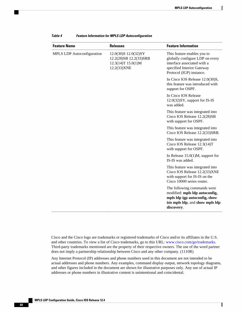
Table 4 Feature Information for MPLS LDP Autoconfiguration
Feature Name Releases Feature Information
MPLS LDP Autoconfiguration 12.0(30)S 12.0(32)SY12.2(28)SB 12.2(33)SRB12.3(14)T 15.0(1)M12.2(33)XNE
This feature enables you toglobally configure LDP on everyinterface associated with aspecified Interior GatewayProtocol (IGP) instance.
In Cisco IOS Release 12.0(30)S,this feature was introduced withsupport for OSPF.
In Cisco IOS Release12.0(32)SY, support for IS-ISwas added.
This feature was integrated intoCisco IOS Release 12.2(28)SBwith support for OSPF.
This feature was integrated intoCisco IOS Release 12.2(33)SRB.
This feature was integrated intoCisco IOS Release 12.3(14)Twith support for OSPF.
In Release 15.0(1)M, support forIS-IS was added.
This feature was integrated intoCisco IOS Release 12.2(33)XNEwith support for IS-IS on theCisco 10000 series router.
The following commands weremodified: mpls ldp autoconfig,mpls ldp igp autoconfig, showisis mpls ldp, and show mpls ldpdiscovery.
Cisco and the Cisco logo are trademarks or registered trademarks of Cisco and/or its affiliates in the U.S.and other countries. To view a list of Cisco trademarks, go to this URL: www.cisco.com/go/trademarks.Third-party trademarks mentioned are the property of their respective owners. The use of the word partnerdoes not imply a partnership relationship between Cisco and any other company. (1110R)
Any Internet Protocol (IP) addresses and phone numbers used in this document are not intended to beactual addresses and phone numbers. Any examples, command display output, network topology diagrams,and other figures included in the document are shown for illustrative purposes only. Any use of actual IPaddresses or phone numbers in illustrative content is unintentional and coincidental.
MPLS LDP Autoconfiguration
MPLS LDP Configuration Guide, Cisco IOS Release 12.464

MPLS LDP Graceful Restart
When a router is configured with Multiprotocol Label Switching (MPLS) Label Distribution Protocol(LDP) Graceful Restart (GR), it assists a neighboring router that has MPLS LDP Stateful Switchover/Nonstop Forwarding (SSO/NSF) Support and Graceful Restart to recover gracefully from an interruptionin service. In this Cisco IOS release, MPLS LDP GR functions strictly in helper mode, which means it canonly help other routers that are enabled with MPLS SSO/NSF and GR to recover. If the router with LDPGR fails, its peer routers cannot help it recover.
Notes:
• MPLS LDP SSO/NSF Support and Graceful Restart is supported in Cisco IOS Release 12.2(25)S.For brevity, this feature is called LDP SSO/NSF in this document.
• The MPLS LDP GR feature described in this document refers to helper mode.
When you enable MPLS LDP GR on a router that peers with an MPLS LDP SSO/NSF-enabled router, theSSO/NSF-enabled router can maintain its forwarding state when the LDP session between them isinterrupted. While the SSO/NSF-enabled router recovers, the peer router forwards packets using staleinformation. This enables the SSO/NSF-enabled router to become operational more quickly.
• Finding Feature Information, page 65• Restrictions, page 65• Information About MPLS LDP Graceful Restart, page 66• How to Configure MPLS LDP Graceful Restart, page 67• Configuration Example for MPLS LDP Graceful Restart, page 69• Additional References, page 72• Feature Information for MPLS LDP Graceful Restart, page 73
Finding Feature InformationYour software release may not support all the features documented in this module. For the latest featureinformation and caveats, see the release notes for your platform and software release. To find informationabout the features documented in this module, and to see a list of the releases in which each feature issupported, see the Feature Information Table at the end of this document.
Use Cisco Feature Navigator to find information about platform support and Cisco software image support.To access Cisco Feature Navigator, go to www.cisco.com/go/cfn. An account on Cisco.com is not required.
Restrictions
MPLS LDP Configuration Guide, Cisco IOS Release 12.4 65

• MPLS LDP GR is supported in strict helper mode.• Tag Distribution Protocol (TDP) sessions are not supported. Only LDP sessions are supported.• MPLS LDP GR cannot be configured on label-controlled ATM (LC-ATM) interfaces.• MPLS LDP SSO/NSF is supported in IOS Release 12.2(25)S. It is not supported in this release.
Information About MPLS LDP Graceful Restart• How MPLS LDP Graceful Restart Works, page 66• How a Route Processor Advertises That It Supports MPLS LDP Graceful Restart, page 67• What Happens If a Route Processor Does Not Have LDP Graceful Restart, page 67
How MPLS LDP Graceful Restart WorksMPLS LDP GR works in strict helper mode, which means it helps a neighboring route processor that hasMPLS LDP SSO/NSF to recover from disruption in service without losing its MPLS forwarding state. Thedisruption in service could be the result of a TCP or UDP event or the stateful switchover of a routeprocessor. When the neighboring router establishes a new session, the LDP bindings and MPLS forwardingstates are recovered.
In the topology shown in the figure below, the following elements have been configured:
• LDP sessions are established between Router 1 and Router 2, as well as between Router 2 and Router3.
• Router 2 has been configured with MPLS LDP SSO/NSF. Routers 1 and 3 have been configured withMPLS LDP GR.
• A label switched path (LSP) has been established between Router 1 and Router 3.
Figure 4 Example of a Network Using LDP Graceful Restart
The following process shows how Routers 1 and 3, which have been configured with LDP GR help Router2, which has been configured with LDP SSO/NSF recover from a disruption in service:
1 Router 1 notices an interruption in service with Router 2. (Router 3 also performs the same actions inthis process.)
2 Router 1 marks all the label bindings from Router 2 as stale, but it continues to use the bindings forMPLS forwarding.
Router 1 reestablishes an LDP session with Router 2, but keeps its stale label bindings. If you issue a showmpls ldp neighbor command with the graceful-restart keyword, the command output displays therecovering LDP sessions.
1 Both routers readvertise their label binding information. If Router 1 relearns a label from Router 2 afterthe session has been established, the stale flags are removed. The show mpls forwarding-tablecommand displays the information in the MPLS forwarding table, including the local label,outgoing label or VC, prefix, label-switched bytes, outgoing interface, and next hop.
You can set various graceful restart timers. See the following commands for more information:
How MPLS LDP Graceful Restart Works Information About MPLS LDP Graceful Restart
MPLS LDP Configuration Guide, Cisco IOS Release 12.466

• mpls ldp graceful-restart timers neighbor-liveness• mpls ldp graceful-restart timers max-recovery
How a Route Processor Advertises That It Supports MPLS LDP GracefulRestart
A route processor that is configured to perform MPLS LDP GR includes the Fault Tolerant (FT) TypeLength Value (TLV) in the LDP initialization message. The route processor sends the LDP initializationmessage to a neighbor to establish an LDP session.
The FT session TLV includes the following information:
• The Learn from Network (L) flag is set to 1, which indicates that the route processor is configured toperform MPLS LDP GR.
• The Reconnect Timeout field shows the time (in milliseconds) that the neighbor should wait for areconnection if the LDP session is lost. In this release, the timer is set to 0, which indicates that if thelocal router fails, its peers should not wait for it to recover. The timer setting indicates that the localrouter is working in helper mode.
• The Recovery Time field shows the time (in milliseconds) that the neighbor should retain the MPLSforwarding state during a recovery. If a neighbor did not preserve the MPLS forwarding state beforethe restart of the control plane, the neighbor sets the recovery time to 0.
What Happens If a Route Processor Does Not Have LDP Graceful RestartIf two route processors establish an LDP session and one route processor is not configured for MPLS LDPGR, the two route processors create a normal LDP session but do not have the ability to perform MPLSLDP GR. Both route processors must be configured for MPLS LDP GR.
How to Configure MPLS LDP Graceful Restart• Configuring MPLS LDP Graceful Restart, page 67
• Verifying the Configuration, page 69
Configuring MPLS LDP Graceful RestartYou must enable MPLS LDP GR on all route processors for an LDP session to be preserved during aninterruption in service.
MPLS LDP GR is enabled globally. When you enable MPLS LDP GR, it has no effect on existing LDPsessions. New LDP sessions that are established can perform MPLS LDP GR.
How a Route Processor Advertises That It Supports MPLS LDP Graceful RestartHow to Configure MPLS LDP Graceful Restart
MPLS LDP Configuration Guide, Cisco IOS Release 12.4 67

SUMMARY STEPS
1. enable
2. configure terminal
3. ip cef [distributed]
4. mpls ldp graceful-restart
5. interface type slot/port
6. mpls ip
7. mpls label protocol {ldp| tdp| both}
DETAILED STEPS
Command or Action Purpose
Step 1 enable
Example:
Router> enable
Enables privileged EXEC mode.
• Enter your password if prompted.
Step 2 configure terminal
Example:
Router# configure terminal
Enters global configuration mode.
Step 3 ip cef [distributed]
Example:
Router(config)# ip cef distributed
Enables Cisco Express Forwarding (CEF).
Step 4 mpls ldp graceful-restart
Example:
Router(config)# mpls ldp graceful-restart
Enables the router to protect the LDP bindings and MPLSforwarding state during a disruption in service.
Step 5 interface type slot/port
Example:
Router(config)# interface pos 3/0
Specifies an interface and enters interface configuration mode.
MPLS LDP Graceful Restart How to Configure MPLS LDP Graceful Restart
MPLS LDP Configuration Guide, Cisco IOS Release 12.468

Command or Action Purpose
Step 6 mpls ip
Example:
Router(config-if)# mpls ip
Configures MPLS hop-by-hop forwarding for an interface.
Step 7 mpls label protocol {ldp| tdp| both}
Example:
Router(config-if)# mpls label protocol ldp
Configures the use of LDP for an interface. You must use LDP.
Note You can also issue the mpls label protocol ldp command in global configuration mode, which enablesLDP on all interfaces configured for MPLS.
Verifying the ConfigurationThe following commands help verify that MPLS LDP GR has been configured correctly:
show mpls ldp neighbor with the graceful-restartkeyword
Displays the Graceful Restart information for LDPsessions.
show mpls ldp graceful-restart Displays Graceful Restart sessions and sessionparameters.
Configuration Example for MPLS LDP Graceful RestartThe figure below shows a configuration where MPLS LDP GR is enabled on Router 1 and MPLS LDPSSO/NSF is enabled on Routers 2 and 3. In this configuration example, Router 1 creates an LDP sessionwith Router 2. Router 1 also creates a targeted session with Router 3 through a traffic engineering tunnelusing Router 2.
Note MPLS LDP SSO/NSF is supported in Cisco IOS Release 12.2(25)S. It is not supported in this release.
Figure 5 MPLS LDP Graceful Restart Configuration Example
Verifying the ConfigurationConfiguration Example for MPLS LDP Graceful Restart
MPLS LDP Configuration Guide, Cisco IOS Release 12.4 69

Router 1 configured with LDP GR:
boot system slot0:rsp-pv-mz hw-module slot 2 image slot0:rsp-pv-mz hw-module slot 3 image slot0:rsp-pv-mz !ip subnet-zeroip cefmpls label range 16 10000 static 10001 1048575mpls label protocol ldpmpls ldp logging neighbor-changesmpls ldp graceful-restartmpls traffic-eng tunnelsno mpls traffic-eng auto-bw timers frequency 0mpls ldp router-id Loopback0 force!interface Loopback0 ip address 20.20.20.20 255.255.255.255 no ip directed-broadcast no ip mroute-cache!interface Tunnel1 ip unnumbered Loopback0 no ip directed-broadcast mpls label protocol ldp mpls ip tunnel destination 19.19.19.19 tunnel mode mpls traffic-eng tunnel mpls traffic-eng autoroute announce tunnel mpls traffic-eng priority 7 7 tunnel mpls traffic-eng bandwidth 500 tunnel mpls traffic-eng path-option 1 dynamic!interface ATM5/1/0 no ip address no ip directed-broadcast atm clock INTERNAL no atm enable-ilmi-trap no atm ilmi-keepalive!interface ATM5/1/0.5 point-to-point ip address 12.0.0.2 255.0.0.0 no ip directed-broadcast no atm enable-ilmi-trap pvc 6/100 encapsulation aal5snapmpls label protocol ldpmpls traffic-eng tunnelsmpls ipip rsvp bandwidth 1000!router ospf 100 log-adjacency-changes redistribute connected network 12.0.0.0 0.255.255.255 area 100 network 20.20.20.20 0.0.0.0 area 100 mpls traffic-eng router-id Loopback0 mpls traffic-eng area 100
Router 2 configured with LDP SSO/NSF:
boot system slot0:rsp-pv-mz hw-module slot 2 image slot0:rsp-pv-mz hw-module slot 3 image slot0:rsp-pv-mz redundancy mode sso!ip cefno ip domain-lookupmpls label range 17 10000 static 10001 1048575mpls label protocol ldp
MPLS LDP Graceful Restart Configuration Example for MPLS LDP Graceful Restart
MPLS LDP Configuration Guide, Cisco IOS Release 12.470

mpls ldp logging neighbor-changesmpls ldp graceful-restartmpls traffic-eng tunnelsno mpls traffic-eng auto-bw timers frequency 0no mpls advertise-labelsmpls ldp router-id Loopback0 force!interface Loopback0 ip address 17.17.17.17 255.255.255.255 no ip directed-broadcast!interface ATM4/0/0 no ip address no ip directed-broadcast no ip mroute-cache atm clock INTERNAL atm sonet stm-1 no atm enable-ilmi-trap no atm ilmi-keepalive!interface ATM4/0/0.5 point-to-point ip address 12.0.0.1 255.0.0.0 no ip directed-broadcast no atm enable-ilmi-trap pvc 6/100 encapsulation aal5snapmpls label protocol ldpmpls traffic-eng tunnelsmpls ipip rsvp bandwidth 1000!interface POS5/1/0 ip address 11.0.0.1 255.0.0.0 no ip directed-broadcast encapsulation ppp mpls label protocol ldp mpls traffic-eng tunnels mpls ip no peer neighbor-route clock source internal ip rsvp bandwidth 1000!router ospf 100 log-adjacency-changes redistribute connected nsf enforce global network 11.0.0.0 0.255.255.255 area 100 network 12.0.0.0 0.255.255.255 area 100 network 17.17.17.17 0.0.0.0 area 100 mpls traffic-eng router-id Loopback0 mpls traffic-eng area 100!ip classless
Router 3 configured with LDP SSO/NSF:
boot system slot0:rsp-pv-mz hw-module slot 2 image slot0:rsp-pv-mz hw-module slot 3 image slot0:rsp-pv-mz redundancy mode sso!ip subnet-zeroip cef!no ip fingerno ip domain-lookupmpls label protocol ldpmpls ldp neighbor 11.11.11.11 targeted ldpmpls ldp logging neighbor-changesmpls ldp graceful-restartmpls traffic-eng tunnels
MPLS LDP Graceful RestartConfiguration Example for MPLS LDP Graceful Restart
MPLS LDP Configuration Guide, Cisco IOS Release 12.4 71

no mpls traffic-eng auto-bw timers frequency 0mpls ldp discovery directed-hello interval 12mpls ldp discovery directed-hello holdtime 130mpls ldp discovery directed-hello acceptmpls ldp router-id Loopback0 force!interface Loopback0 ip address 19.19.19.19 255.255.255.255 no ip directed-broadcast!interface POS1/0 ip address 11.0.0.2 255.0.0.0 no ip directed-broadcast encapsulation ppp mpls label protocol ldp mpls traffic-eng tunnels mpls ip no peer neighbor-route clock source internal ip rsvp bandwidth 1000!router ospf 100 log-adjacency-changes redistribute connected nsf enforce globalnetwork 11.0.0.0 0.255.255.255 area 100network 19.19.19.19 0.0.0.0 area 100mpls traffic-eng router-id Loopback0 mpls traffic-eng area 100!ip classless
Additional ReferencesRelated Documents
Related Topic Document Title
MPLS Label Distribution Protocol MPLS Label Distribution Protocol (LDP)
Standards
Standards Title
None —
MIBs
MIBs1 MIBs Link
• MPLS Label Distribution Protocol MIBVersion 8 Upgrade
To locate and download MIBs for selectedplatforms, Cisco IOS releases, and feature sets, useCisco MIB Locator found at the following URL:
http://www.cisco.com/go/mibs
1 Not all supported MIBs are listed.
MPLS LDP Graceful Restart Additional References
MPLS LDP Configuration Guide, Cisco IOS Release 12.472

RFCs
RFCs2 Title
RFC 3036 LDP Specification
RFC 3478 Graceful Restart Mechanism for Label Distribution
Technical Assistance
Description Link
The Cisco Technical Support & Documentationwebsite contains thousands of pages of searchabletechnical content, including links to products,technologies, solutions, technical tips, and tools.Registered Cisco.com users can log in from thispage to access even more content.
http://www.cisco.com/techsupport
Feature Information for MPLS LDP Graceful RestartThe following table provides release information about the feature or features described in this module.This table lists only the software release that introduced support for a given feature in a given softwarerelease train. Unless noted otherwise, subsequent releases of that software release train also support thatfeature.
Use Cisco Feature Navigator to find information about platform support and Cisco software image support.To access Cisco Feature Navigator, go to www.cisco.com/go/cfn. An account on Cisco.com is not required.
2 Not all supported RFCs are listed.
MPLS LDP Graceful RestartFeature Information for MPLS LDP Graceful Restart
MPLS LDP Configuration Guide, Cisco IOS Release 12.4 73

Table 5 Feature Information for MPLS LDP Graceful Restart
Feature Name Releases Feature Information
MPLS LDP Graceful Restart 12.0(29)S 12.3(14)T12.2(33)SRA
MPLS LDP Graceful Restartassists a neighboring router thathas MPLS LDP StatefulSwitchover/Nonstop Forwarding(SSO/NSF) Support and GracefulRestart to recover gracefully froman interruption in service.
In Cisco IOS Release 12.0(29)S,this feature was introduced.
This feature was integrated intoCisco IOS Release 12.3(14)T.
This feature was integrated intoCisco IOS Release 12.2(33)SRA.
The following sections provideinformation about this feature:
The following commands wereintroduced or modified:
• debug mpls ldp graceful-restart
• mpls ldp graceful-restart• mpls ldp graceful-restart
timers max-recovery• mpls ldp graceful-restart
timers neighbor-liveness• show mpls ip binding• show mpls ldp bindings• show mpls ldp graceful-
restart• show mpls ldp neighbor
Cisco and the Cisco logo are trademarks or registered trademarks of Cisco and/or its affiliates in the U.S.and other countries. To view a list of Cisco trademarks, go to this URL: www.cisco.com/go/trademarks.Third-party trademarks mentioned are the property of their respective owners. The use of the word partnerdoes not imply a partnership relationship between Cisco and any other company. (1110R)
Any Internet Protocol (IP) addresses and phone numbers used in this document are not intended to beactual addresses and phone numbers. Any examples, command display output, network topology diagrams,and other figures included in the document are shown for illustrative purposes only. Any use of actual IPaddresses or phone numbers in illustrative content is unintentional and coincidental.
MPLS LDP Graceful Restart
MPLS LDP Configuration Guide, Cisco IOS Release 12.474