motor controller sfc-dc - festo.com · spanish french italian swedish 540417 540418 540419 ... also...
TRANSCRIPT
Brief overview
SFC-DC-...-IOSFC-DC-...-PBSFC-DC-...-COSFC-DC-...-DN
– English
80814842018-01f[8081486]
Motor controller SFC-DC
Festo SFC-DC- 2018-01f 2
Translation of the original instructions
Documentation on the product
For all available product documentation
� www.festo.com/pk
Copyright:
Festo AG & Co.Ruiter Straße 8273734 Esslingen Germany
Internet: �http://www.festo.comE-Mail: �[email protected]
Reproduction, distribution or sale of this document or communication ofits contents to others without express authorization is prohibited. Offenders will be liable for damages. All rights reserved in the event thata patent, utility model or design patent is registered.
English 3 . . . . . . . . . . . . . . . . . . . . . . . . . . . . . . . . . . . . . . . . . . . .
Festo SFC-DC- 2018-01f English 3
1 User instructionsEnglish
The motor controller type SFC-DC-... serves as a positioncontroller and position servo control for the electricmini-slide type SLTE and the grippers HGPLE, HGPPE(depends on firmware status, see manual).The higher-order PLC/IPC is connected via the controllerinterface:
– Type SFC-DC-...-IO: digital I/O modules
– Type SFC-DC-...-PB: PROFIBUS-DP
– Type SFC-DC-...-CO: CANopen
– Type SFC-DC-...-DN: DeviceNet
Commissioning and parameterisation use:
– the FCT software package and the SFC-DC plugin viathe RS232 interface or
– for type SFC-DC-...-H2-... optionally with the controlpanel (display and four operating buttons).
NoteThis brief overview is part of the operator packageP.BP-SFC-DC. It serves only as initial information anddoes not replace the complete documentation, which iscontained as a PDF file on the CD ROM supplied (seetable).� It is essential that you observe the information and
the safety instructions in the complete manual for theSingle Field Controller.
� Please consult your local Festo Service or write to thefollowing e-mail address if you have any technicalproblems: [email protected]
Festo SFC-DC- 2018-01f English4
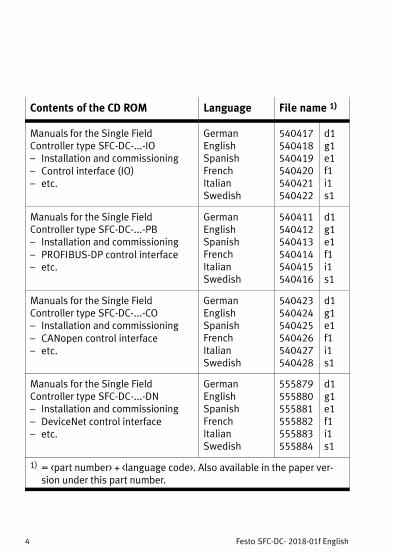
Contents of the CD ROM Language File name 1)
Manuals for the Single FieldController type�SFC-DC-...-IO– Installation and commissioning– Control interface (IO)– etc.
GermanEnglishSpanishFrenchItalianSwedish
540417540418540419540420540421540422
d1g1e1f1i1s1
Manuals for the Single FieldController type�SFC-DC-...-PB– Installation and commissioning– PROFIBUS-DP control interface– etc.
GermanEnglishSpanishFrenchItalianSwedish
540411540412540413540414540415540416
d1g1e1f1i1s1
Manuals for the Single FieldController type�SFC-DC-...-CO– Installation and commissioning– CANopen control interface– etc.
GermanEnglishSpanishFrenchItalianSwedish
540423540424540425540426540427540428
d1g1e1f1i1s1
Manuals for the Single FieldController type�SFC-DC-...-DN– Installation and commissioning– DeviceNet control interface– etc.
GermanEnglishSpanishFrenchItalianSwedish
555879555880555881555882555883555884
d1g1e1f1i1s1
1) = <part number> + <language code>. Also available in the paper version under this part number.
Festo SFC-DC- 2018-01f English 5
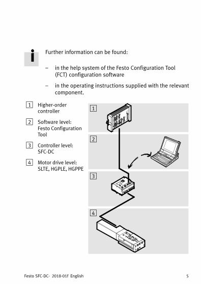
Further information can be found:
– in the help system of the Festo Configuration Tool(FCT) configuration software
– in the operating instructions supplied with the relevantcomponent.
1 Higher-ordercontroller
2 Software level:Festo ConfigurationTool
3 Controller level: SFC-DC
4 Motor drive level:SLTE, HGPLE, HGPPE
1
2
3
4
Festo SFC-DC- 2018-01f English6
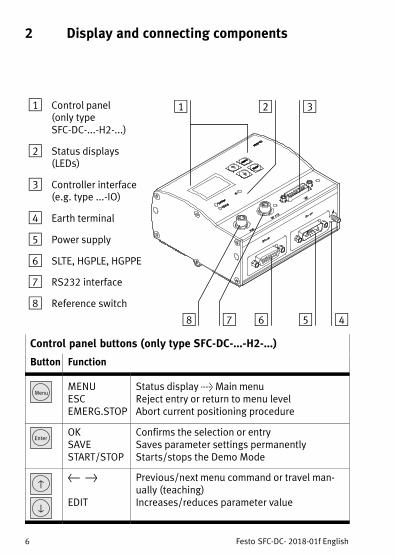
2 Display and connecting components
1 Control panel (only typeSFC-DC-...-H2-...)
2 Status displays(LEDs)
3 Controller interface(e.g. type ...-IO)
4 Earth terminal
5 Power supply
6 SLTE, HGPLE, HGPPE
7 RS232 interface
8 Reference switch
1 2
4567
3
8
Control panel buttons (only type SFC-DC-...-H2-...)
Button Function
MenuMENUESCEMERG.STOP
Status display > Main menuReject entry or return to menu levelAbort current positioning procedure
EnterOKSAVESTART/STOP
Confirms the selection or entrySaves parameter settings permanentlyStarts/stops the Demo Mode
v
V
{ }
EDIT
Previous/next menu command or travel manually (teaching)Increases/reduces parameter value
Festo SFC-DC- 2018-01f English 7
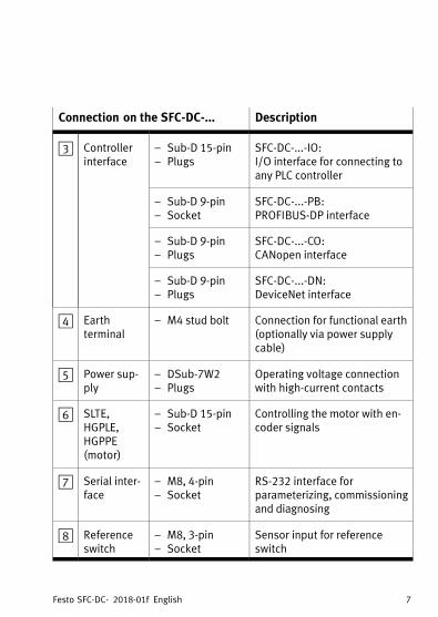
Connection on the SFC-DC-... Description
3 Controllerinterface
– Sub-D 15-pin– Plugs
SFC-DC-...-IO: I/O interface for connecting toany PLC controller
– Sub-D 9-pin– Socket
SFC-DC-...-PB:PROFIBUS-DP interface
– Sub-D 9-pin– Plugs
SFC-DC-...-CO:CANopen interface
– Sub-D 9-pin– Plugs
SFC-DC-...-DN:DeviceNet interface
4 Earthterminal
– M4 stud bolt Connection for functional earth(optionally via power supplycable)
5 Power supply
– DSub-7W2– Plugs
Operating voltage connectionwith high-current contacts
6 SLTE,HGPLE,HGPPE(motor)
– Sub-D 15-pin– Socket
Controlling the motor with encoder signals
7 Serial interface
– M8, 4-pin– Socket
RS-232 interface forparameterizing, commissioningand diagnosing
8 Referenceswitch
– M8, 3-pin– Socket
Sensor input for referenceswitch
Festo SFC-DC- 2018-01f English8
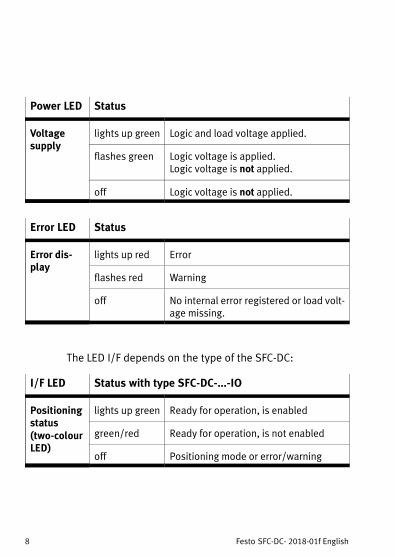
Power LED Status
Voltagesupply
lights up green Logic and load voltage applied.
flashes green Logic voltage is applied.Logic voltage is not applied.
off Logic voltage is not applied.
Error LED Status
Error display
lights up red Error
flashes red Warning
off No internal error registered or load voltage missing.
The LED I/F depends on the type of the SFC-DC:
I/F LED Status with type SFC-DC-...-IO
Positioningstatus(two-colourLED)
lights up green Ready for operation, is enabled
green/red Ready for operation, is not enabled
off Positioning mode or error/warning

Festo SFC-DC- 2018-01f English 9
I/F LED Status with type SFC-DC-...-PB
Green: Positioningstatus
lights up green MC (motion complete)
off No MC or error/warning
Red: Bus status
off Data exchange active
flashes quickly Address not parameterized
flashes slowly Wait for connection
I/F LED Status with type SFC-DC-...-CO
Green: Statemachine
ON
OFF
CAN status ”operational” (on)
ON
OFF
CAN status ”stopped” (single flash)
ON
OFF
CAN status ”pre-operational” (blinking)
Red: Bus connection
ON
OFF
Connection error free (off )
ON
OFF
CAN warning limit reached (single flash)
ON
OFFCAN node guarding error (double flash)
ON
OFF
Bus parameter not parameterised or external CAN supply missing (on)
Festo SFC-DC- 2018-01f English10
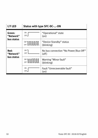
I/F LED Status with type SFC-DC-...-DN
Green: “Network”bus status
ON
OFF
“Operational” state (on)
ON
OFF
“Device Standby” status (blinking)
Red: “Network”bus status
ON
OFF
No bus connection “No Power/Bus-Off ”(off )
ON
OFF
Warning “Minor fault”(blinking)
ON
OFF
Fault “Unrecoverable fault”(on)
Festo SFC-DC- 2018-01f English 11
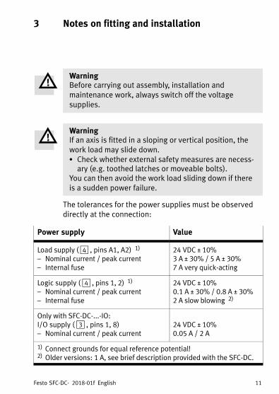
3 Notes on fitting and installation
WarningBefore carrying out assembly, installation andmaintenance work, always switch off the voltagesupplies.
WarningIf an axis is fitted in a sloping or vertical position, thework load may slide down.� Check whether external safety measures are necess
ary (e.g. toothed latches or moveable bolts).You can then avoid the work load sliding down if thereis a sudden power failure.
The tolerances for the power supplies must be observeddirectly at the connection:
Power supply Value
Load supply ( 4� , pins A1, A2) 1)
– Nominal current / peak current– Internal fuse
24 VDC ± 10%3 A ± 30% / 5 A ± 30%7 A very quick-acting
Logic supply ( �4 , pins 1, 2) 1)
– Nominal current / peak current– Internal fuse
24 VDC ± 10%0.1 A ± 30% / 0.8 A ± 30%2 A slow blowing 2)
Only with SFC-DC-...-IO:I/O supply (� 3 �, pins 1, 8)– Nominal current / peak current
24 VDC ± 10%0.05 A / 2 A
1) Connect grounds for equal reference potential!2) Older versions: 1 A, see brief description provided with the SFC-DC.
Festo SFC-DC- 2018-01f English12
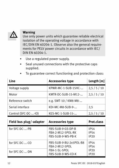
WarningUse only power units which guarantee reliable electricalisolation of the operating voltage in accordance withIEC/DIN EN 60204-1. Observe also the general requirements for PELV power circuits in accordance with IEC/DIN EN 60204-1.
� Use a regulated power supply.
� Seal unused connections with the protective capssupplied.
� To guarantee correct functioning and protection class:
Line Accessories type Length [m]
Voltage supply KPWR-MC-1-SUB-15HC-... 2,5 / 5 / 10
Motor KMTR-DC-SUB-15-M12-... 2,5 / 5 / 10
Reference switch e.g. SMT-10 / KM8-M8-...
Serial interface KDI-MC-M8-SUB-9-... 2,5
Control (SFC-DC-...-IO) KES-MC-1-SUB-15-... 2,5 / 5 / 10
Field bus plug/-adapter Accessories type Prot.class
for SFC-DC-...-PB FBS-SUB-9-GS-DP-BFBA-2-M12-5POL-RKFBS-SUB-9-WS-PB-K
IP54IP54IP20
for SFC-DC-...-CO FBS-SUB-9-BU-2x5POL-B8FBA-2-M12-5POLFBA-1-SL-5POLFBS-SUB-9-WS-CO-K
IP54IP54IP20IP20
for SFC-DC-...-DN
Festo SFC-DC- 2018-01f English 13
4 Notes on commissioning and operation
WarningElectric axes can move suddenly with high force and athigh speed. Collisions can lead to serious injuries andto damage to components.� Make sure that nobody can gain access to the
operating range of the axes or other connectedactuators and that no items lie in the travel rangewhile the system is still connected to energy sources.
WarningDanger of injury.Errors in parameterization can cause injuries anddamage to property. In the following cases, homing isabsolutely essential in order that the referencecoordinates and the operating area can be set correctly:‒ for initial commissioning‒ when the referencing method is changed‒ each time the logic voltage supply is switched on.
Carry out commissioning with the Festo Configuration Toolconfiguration software (see FCT help system), or optionallywith the control panel (only type SFC-DC-...-H2).
Festo SFC-DC- 2018-01f English14
During commissioning, the following must be definedfor example:
� Select the drive type and, if necessary, adapt the parameterization to the axis.
� Set the parameters for homing.
� Define the axis zero point and the operating area(software end positions).
� Define position records (target position, positioningmode, traversing speed, accelerations).
Carry out the following steps in order to complete commissioning:
1. Carry out homing.
2. Check the positioning behaviour of the axis, referencecoordinates and operating area (test run).
3. If necessary, optimize the settings of the position records, reference coordinates and operating area.
4. Test the controller interface (device control with control panel HMI = off ).
Each time the operating voltage is switched on you must:
� Carry out reference travel.