motif es owners manual
TRANSCRIPT

MOTIF ES Owner‘s ManualEnglish

SPECIAL MESSAGE SECTION
PRODUCT SAFETY MARKINGS: Yamaha electronic products may Battery Notice: This product MAY contain a small non-rechargable
have either labels similar to the graphics shown below ormolded/stamped facsimiles of these graphics on the enclosure.The explanation of these graphics appears on this page. Pleaseobserve all cautions indicated on this page and those indicatedin the safety instruction section.The exclamation point within the equilateral triangle is intended to alert the user to the presence of important operating and maintenance (servicing) instructions in the literature accompanying the product.
The lightning flash with arrowhead symbol, withinthe equilateral triangle, is intended to alert theuser to the presence of uninsulated “dangerousvoltage” within the product’s enclosure that maybe of sufficient magnitude to constitute a risk ofelectrical shock.
IMPORTANT NOTICE: All Yamaha electronic products are tested andapproved by an independent safety testing laboratory in order that youmay be sure that when it is properly installed and used in its normal andcustomary manner, all foreseeable risks have been eliminated. DO NOTmodify this unit or commission others to do so unless specificallyauthorized by Yamaha. Product performance and/or safety standardsmay be diminished. Claims filed under the expressed warranty may bedenied if the unit is/has been modified. Implied warranties may also beaffected.
SPECIFICATIONS SUBJECT TO CHANGE: The informationcontained in this manual is believed to be correct at the time of printing.However, Yamaha reserves the right to change or modify any of thespecifications without notice or obligation to update existing units.
ENVIRONMENTAL ISSUES: Yamaha strives to produce products thatare both user safe and environmentally friendly. We sincerely believethat our products and the production methods used to produce them,meet these goals. In keeping with both the letter and the spirit of the law,we want you to be aware of the following:
CAUTIONRISK OF ELECTRIC SHOCK
DO NOT OPEN
CAUTION: TO REDUCE THE RISK OF ELECTRIC SHOCK.DO NOT REMOVE COVER (OR BACK).
NO USER-SERVICEABLE PARTS INSIDE.REFER SERVICING TO QUALIFIED SERVICE PERSONNEL.
92-469- ➀ (rear)
battery which (if applicable) is soldered in place. The average life spanof this type of battery is approximately five years. When replacementbecomes necessary, contact a qualified service representative toperform the replacement.
Warning: Do not attempt to recharge, disassemble, or incinerate thistype of battery. Keep all batteries away from children. Dispose of usedbatteries promptly and as regulated by applicable laws. Note: In someareas, the servicer is required by law to return the defective parts.However, you do have the option of having the servicer dispose of theseparts for you.
Disposal Notice: Should this product become damaged beyondrepair, or for some reason its useful life is considered to be at an end,please observe all local, state, and federal regulations that relate to thedisposal of products that contain lead, batteries, plastics, etc.
NOTICE: Service charges incurred due to lack of knowledge relating tohow a function or effect works (when the unit is operating as designed)are not covered by the manufacturer’s warranty, and are therefore theowners responsibility. Please study this manual carefully and consultyour dealer before requesting service.
NAME PLATE LOCATION: The graphic below indicates the locationof the name plate. The model number, serial number, powerrequirements, etc., are located on this plate. You should record themodel number, serial number, and the date of purchase in the spacesprovided below and retain this manual as a permanent record of yourpurchase.
Model
Serial No.
Purchase Date
BREATH ASOUTTHRU
USB
TO HOSTTO DEVICEmLAN I/O EXPANSIONAC INLETPOWER
ON OFF INMIDI
mLAN I/O EXPANSIONAC INLETPOWER
ON OFF
mLAN I/O EXPANSIONAC INLETPOWER
ON OFF
MOTIF ES6
MOTIF ES7
MOTIF ES8

IMPORTANT SAFETY INSTRUCTIONS
INFORMATION RELATING TO PERSONAL INJURY, ELECTRICAL SHOCK, AND FIRE HAZARD POSSIBILITIES HAS BEEN INCLUDED IN THIS LIST.
WARNING- When using any electrical or electronic product, basic 8. This product was NOT designed for use in wet/damp locations and
precautions should always be followed. These precautions include, butare not limited to, the following:1. Read all Safety Instructions, Installation Instructions, SpecialMessage Section items, and any Assembly Instructions found in thismanual BEFORE making any connections, including connection to themain supply.
2. Do not attempt to service this product beyond that described in theuser-maintenance instructions. All other servicing should be referred toqualified service personnel.
3. Main Power Supply Verification: Yamaha products aremanufactured specifically for the supply voltage in the area where theyare to be sold. If you should move, or if any doubt exists about thesupply voltage in your area, please contact your dealer for supplyvoltage verification and (if applicable) instructions. The required supplyvoltage is printed on the name plate. For name plate location, pleaserefer to the graphic found in the Special Message Section of thismanual.
4. DANGER-Grounding Instructions: This product must be groundedand therefore has been equipped with a three pin attachment plug. Ifthis product should malfunction, the ground pin provides a path of lowresistance for electrical current, reducing the risk of electrical shock. Ifyour wall socket will not accommodate this type plug, contact anelectrician to have the outlet replaced in accordance with localelectrical codes. Do NOT modify the plug or change the plug to adifferent type!
5. WARNING: Do not place this product or any other objects on thepower cord or place it in a position where anyone could walk on, tripover, or roll anything over power or connecting cords of any kind. Theuse of an extension cord is not recommended! If you must use anextension cord, the minimum wire size for a 25’ cord (or less) is 18 AWG.NOTE: The smaller the AWG number, the larger the current handlingcapacity. For longer extension cords, consult a local electrician.
6. Ventilation: Electronic products, unless specifically designed forenclosed installations, should be placed in locations that do notinterfere with proper ventilation. If instructions for enclosed installationsare not provided, it must be assumed that unobstructed ventilation isrequired.
7. Temperature considerations: Electronic products should beinstalled in locations that do not seriously contribute to their operatingtemperature. Placement of this product close to heat sources such as;radiators, heat registers etc., should be avoided.
should not be used near water or exposed to rain. Examples of wet /damp locations are; near a swimming pool, spa, tub, sink, or wetbasement.
9. This product should be used only with the components supplied or;a cart,rack, or stand that is recommended by the manufacturer. If a cart,rack, or stand is used, please observe all safety markings andinstructions that accompany the accessory product.
10. The power supply cord (plug) should be disconnected from theoutlet when electronic products are to be left unused for extendedperiods of time. Cords should also be disconnected when there is ahigh probability of lightning and/or electrical storm activity.
11. Care should be taken that objects do not fall and liquids are notspilled into the enclosure through any openings that may exist.
12. Electrical/electronic products should be serviced by a qualifiedservice person when:
a. The power supply cord has been damaged; orb. Objects have fallen, been inserted, or liquids have been spilled
into the enclosure through openings; orc. The product has been exposed to rain; ord. The product does not operate, exhibits a marked change in
performance; ore. The product has been dropped, or the enclosure of the product
has been damaged.
13. This product, either alone or in combination with an amplifierand headphones or speaker/s, may be capable of producing soundlevels that could cause permanent hearing loss. DO NOT operate for along period of time at a high volume level or at a level that isuncomfortable. If you experience any hearing loss or ringing in the ears,you should consult an audiologist. IMPORTANT: The louder the sound, the shorter the time period beforedamage occurs.
14. Some Yamaha products may have benches and/or accessorymounting fixtures that are either supplied as a part of the product or asoptional accessories. Some of these items are designed to be dealerassembled or installed. Please make sure that benches are stable andany optional fixtures (where applicable) are well secured BEFOREusing. Benches supplied by Yamaha are designed for seating only. Noother uses are recommended.
PLEASE KEEP THIS MANUAL92-469-3

PRECAUTIONSPLEASE READ CAREFULLY BEFORE PROCEEDING
* Please keep this manual in a safe place for future reference.
WARNINGAlways follow the basic precautions listed below to avoid the possibility of serious injury or even death from electrical shock, short-circuiting, damages, fire or other hazards. These precautions include, but are not limited to, the following:
• Only use the voltage specified as correct for the instrument. The required voltage is printed on the name plate of the instrument.
• Check the electric plug periodically and remove any dirt or dust which may have accumulated on it.
• Use only the supplied power cord/plug.
• Do not place the power cord near heat sources such as heaters or radiators, and do not excessively bend or otherwise damage the cord, place heavy objects on it, or place it in a position where anyone could walk on, trip over, or roll anything over it.
• This instrument contains no user-serviceable parts. Do not attempt to disassemble or modify the internal components in any way.
Power supply/AC power adaptor
Do not open
(2)-8
• Do not expose the instrument to rain, use it near water or in damp or wet conditions, or place containers on it containing liquids which might spill into any openings.
• Never insert or remove an electric plug with wet hands.
• Do not put burning items, such as candles, on the unit. A burning item may fall over and cause a fire.
• If the power cord or plug becomes frayed or damaged, or if there is a sudden loss of sound during use of the instrument, or if any unusual smells or smoke should appear to be caused by it, immediately turn off the power switch, disconnect the electric plug from the outlet, and have the instrument inspected by qualified Yamaha service personnel.
Water warning
Fire warning
If you notice any abnormality
CAUTIONAlways follow the basic precautions listed below to avoid the possibility of physical injury to you or others, or damage to the instrument or other property. These precautions include, but are not limited to, the following:
• Always connect the three-pin attachment plug to a properly grounded power source. (For more information about the main power supply, see page 26.)
• When removing the electric plug from the instrument or an outlet, always hold the plug itself and not the cord. Pulling by the cord can damage it.
• Remove the electric plug from the outlet when the instrument is not to be used for extended periods of time, or during electrical storms.
• Do not connect the instrument to an electrical outlet using a multiple-connector. Doing so can result in lower sound quality, or possibly cause overheating in the outlet.
Power supply/Power cord
• Do not expose the instrument to excessive dust or vibrations, orextreme cold or heat (such as in direct sunlight, near a heater, or in a car during the day) to prevent the possibility of panel disfiguration or damage to the internal components.
• Do not use the instrument in the vicinity of a TV, radio, stereo equipment, mobile phone, or other electric devices. Otherwise, the instrument, TV, or radio may generate noise.
• Do not place the instrument in an unstable position where it might accidentally fall over.
• Before moving the instrument, remove all connected cables.
• Do not place objects in front of the instrument’s air vent, since this may prevent adequate ventilation of the internal components, and possibly result in the instrument overheating.
Location
1
/2
• Before connecting the instrument to other electronic components, turn off the power for all components. Before turning the power on or off for all components, set all volume levels to minimum. Also, be sure to set the volumes of all components at their minimum levels and gradually raise the volume controls while playing the instrument to set the desired listening level.
• When cleaning the instrument, use a soft, dry cloth. Do not use paint thinners, solvents, cleaning fluids, or chemical-impregnated wiping cloths.
• Do not insert a finger or hand in any gaps on the key cover or instrument.
• Never insert or drop paper, metallic, or other objects into the gaps on the panel or keyboard. If this happens, turn off the power immediately and unplug the power cord from the AC outlet. Then have the instrument inspected by qualified Yamaha service personnel.
• Do not place vinyl, plastic or rubber objects on the instrument, since this might discolor the panel or keyboard.
• Do not rest your weight on, or place heavy objects on the instrument, and do not use excessive force on the buttons, switches or connectors.
• Do not operate the instrument for a long period of time at a high or uncomfortable volume level, since this can cause permanent hearing loss. If you experience any hearing loss or ringing in the ears, consult a physician.
Connections
Maintenance
Handling caution
(2)-8
Saving and backing up your data• DRAM data (see page 186) is lost when you turn off the power to
the instrument. Save the data to a SmartMedia/USB storage device.
• Never attempt to turn off the power while data is being written to Flash ROM (while an “Executing...” or “Please keep power on” message is shown). Turning the power off in this state results in loss of all user data and may cause the system to freeze (due to corruption of data in the Flash ROM). This means that this synthesizer may not be able to start up properly, even when turning the power on next time.
Backing up the SmartMedia/external media• To protect against data loss through media damage, we
recommend that you save your important data onto two SmartMedia/external media.
Saving data
Yamaha cannot be held responsible for damage caused by improper use or modifications to the instrument, or data that is lost or destroyed.
Always turn the power off when the instrument is not in use.
2
/2
Introduction
6
IntroductionCongratulations and thank you for your purchase of the Yamaha MOTIF ES6/MOTIF ES7/MOTIF ES8 Music Production Synthesizer!You now own what is perhaps the best-sounding, most versatile, and certainly most powerful synthesizer and total music production instrument on the planet.We strove to put virtually all our synthesizer technology and music making know-how into one instrument — and we succeeded. The new MOTIF ES not only gives you the latest and greatest sounds and rhythms (as well as the ability to create and sample your own), it gives you powerful, easy-to-use tools for playing, combining and controlling these dynamic sounds/rhythms — in real time, as you perform!Take time to look through this manual carefully. It’s packed with important information on how to get the most from this amazing instrument.Dive in now and enjoy!
AccessoriesThe following items have been included with your MOTIF ES 6/MOTIF ES 7/MOTIF ES 8. Check to see that you have everything listed here.
• AC Power cord • CD-ROM x 3• Owner’s Manual (this book) • Data List • Installation Guide
• Copying of commercially available music sequence data and/or digital audio files for any purpose other than your own personal use is strictly prohibited.
About the included CD-ROMsThe following three CD-ROMs are included in the MOTIF ES package.
• TOOLS for MOTIF ES6/MOTIF ES7/MOTIF ES8This CD-ROM contains special software for use with this instrument. It includes the latest version of SQ01 (V2), a full-featured audio/MIDI sequencer/mixer for comprehensive music production, Voice Editor, which gives you comprehensive and intuitive sound editing tools, and Multi Part Editor, for editing the Mixing parameters of Songs and Patterns.For details, see the separate Installation Guide or the online manuals included with the software.
• Sound Library for MOTIF ES6/MOTIF ES7/MOTIF ES8This CD-ROM contains various types of data for use with the MOTIF ES. For information on the contents, refer to the List file in the CD-ROM. You can use the data by loading it in the File mode. Insert the CD-ROM into a CD-ROM drive* connected to the USB TO DEVICE connector via USB and execute the Load operation. Alternately, you can access the data from a USB storage device (such as a hard disk) or a SmartMedia card (inserted to the CARD slot) to which the data has been copied.For details about how to load each type of data, refer to the following pages.
• Voice extension: W7V page 87• Pattern extension: W7P page 133• WAV file extension: WAV pages 100 and 109
* For information on what USB devices (model name, etc.) can be used with the MOTIF ES, see page 29.
n If you are loading audio WAV files, make sure that DIMM modules are installed to the imt. (For DIMM compatibility information, see page 289.) Also, when loading Voice data from this CD-ROM, make sure to install DIMM modules, because the Voice data contains User Waveforms. If DIMM modules are not installed, an error message appears when you try to load a WAV file or Voice data from this CD-ROM.
• TOOLS for Modular Synthesis Plug-in SystemThis CD-ROM contains a variety of computer applications, including the Voice Editor for editing Voices of the optional Plug-in Boards. For more information, refer to the “Readme” file in the CD-ROM.
Owner’s Manual

Main Features
Main Features
Wide range of dynamic and authentic voices. Use the Category Search function to quickly call up the sounds you want, based on their instrument type.Performance mode lets you use four different voices together — in layers or in a keyboard split.
Integrated Sampling Sequencer — seamlessly combines audio and MIDI recording.
• Full Sample recording and editing features, and up to 512MB of sample memory (with optional DIMM modules).
• Wide data compatibility lets you load AIFF and WAV files, as well as samples and program/voice data from other popular samplers, such as the Yamaha A-series.
• Convenient Resampling function lets you sample the sound of the MOTIF itself directly. Play your own melodies, riffs and rhythms — and use them as samples.
• Unique Slice feature automatically chops up your rhythms and riffs into their individual beats and notes. This lets you manipulate the component parts of your sample loops as MIDI data, and gives you the power to easily change tempo and even the rhythmic feel, without disturbing the pitch or sound quality.
Extensive effect processing, with Reverb (20 types), Chorus (49 types), eight separate Insertion blocks each of which has two blocks (total 116 types), Master Effect (8 types), and a digital equalizer (3-band Part EQ and 5-band Master EQ).
Comprehensive real-time control with four knobs and four sliders — letting you adjust filter, levels, effects, EG, and more, while you play.
Pattern mode functions let you craft different rhythmic sections and riffs as individual elements — which you can easily and intuitively combine in real time to create full rhythm tracks.
In addition to being able to create User voices in the Voice mode, you can create special Mixing voices for Songs and Patterns. These voices can be edited and stored in the Song/Pattern mode, making it exceptionally easy and convenient to create voices for use with Songs and Patterns.
The versatile Arpeggio feature automatically plays a variety of sequenced phrases in response to the keys you play. This function is especially powerful with drum voices — letting you easily call up various rhythm patterns at the touch of a key, and providing instant inspiration for song creation and performance. When used with normal voices, the Arpeggio phrase changes harmonically and melodically with the chords you play, giving you intuitive control over the patterns as you compose or perform. Arpeggios can be triggered not only according to the keys you play, but also by how strongly you play them — for even greater performance power.
Page 60
Page 67
Page 172
Page 289
Page 100, 270
Page 99
Page 107
Page 177
Page 50
Page 106
Page 105
Page 66
Once you’ve collected all the audio samples, loops, MIDI data, and patterns you need for your song, use Pattern Chain to arrange the pieces in real time. This hands-on approach makes it easier than ever to come up with great ideas and amazing songs.
Song Scene is another powerful tool that lets you take “snapshots” of the sequencer track settings (such as pan, volume, track mute and so on). Then, during playback or recording, simply switch among the Scenes for instant, dynamic changes.
Master mode — for using the MOTIF ES as a master keyboard controller (with independent Zones), and for easily reconfiguring the instrument between Voice/Performance play and Song/Pattern play in live applications.
Exceptionally easy-to-understand interface with two-tiered operation buttons: [F1] - [F6] and [SF1] - [SF5]
Remote Control — for operating your favorite sequencing software from the panel controls. Mute tracks, control transport (Play, Stop, Record, etc.), mix both MIDI and audio tracks (up to 16) with this instrument’s knobs and sliders, pan the tracks, control EQ, and tweak effect sends — all without ever touching the mouse.
Three Modular Synthesis Plug-in System slots let you upgrade the MOTIF ES with a completely new synthesizer or sound-processing engine. These Plug-in boards give you more voices, more effects, more polyphony and more instrument parts. Plus, special Plug-in voices have already been programmed and stored to the MOTIF ES, ready to be played as soon as you install the proper board.
A full rear panel of input/output connections provides maximum interfacing flexibility. These include Assignable Outputs, A/D Inputs, MIDI, two USB connectors and a memory card slot. Moreover, an optional AIEB2 or mLAN16E board can be installed. The mLAN interface is particularly powerful — making it possible to transfer both digital audio and MIDI data via a single broadband cable.
The instrument features two USB connectors — USB TO HOST for connecting to computer, and USB TO DEVICE for connecting to storage devices, such as a hard disk drive or flash disk.
Included software — the CD-ROM accompanying your instrument (Tools for MOTIF ES) features a variety of convenient and powerful programs for using the MOTIF ES with a computer. These include the Voice Editor which provides comprehensive, easy-to-use editing features and parameters, and a Multi Part Editor for intuitive editing of Song/Pattern Mixing parameters from your computer screen.
Page 115
Page 123
Page 136
Page 47
Page 147
Page 74
Page 39
Page 29
Page 142
Ow
7ner’s Manual
How to use this manual
8
How to use this manualThe Controls & Connectors ...............................................................................................Page 16Use this section to find out about all of the buttons, controls and connectors of this instrument.
Setting Up ..........................................................................................................................Page 26Before going on to any other part of the manual, we strongly suggest you read this section first. It shows you how to get started playing and using your new instrument.
Application Index ................................................................................................................Page 9This special index is organized not by single words, but by functions and applications — allowing you to quickly and easily find how to perform a particular operation or explore a topic of interest.
Basic Structure .................................................................................................................Page 154This section provides a detailed overview of all of the main functions and features of this instrument, and shows how they fit together.
Basic Operation..................................................................................................................Page 45This section introduces you to the basic operating conventions of this instrument, such as editing values and changing settings.
Quick Guide........................................................................................................................Page 55In this tutorial section, you will take a guided tour through the various functions of this instrument, and get some hands-on experience in playing and using it.
Reference .........................................................................................................................Page 188The MOTIF ES encyclopedia. This section explains all parameters, settings, functions, features, modes and operations in full detail.
Troubleshooting...............................................................................................................Page 279If this instrument does not function as expected or you have some problem with the sound or operation, refer to this section before calling your Yamaha dealer or service center. Most common problems and their solutions are covered here in a very simple and easy-to-understand way.
Appendix..........................................................................................................................Page 275This section contains detailed information on this instrument such as Specifications and an Alert Message List as well as instructions for installing optional equipment (e.g., DIMM modules, AIEB2, mLAN16E interface, and Plug-in Boards).
Data List (separate booklet)This contains various important lists such as the Voice List, Preset Pattern Phrase List, Effect List, MIDI Data Format, and MIDI Implementation Chart.
Installation Guide (separate booklet)Refer to this for instructions on installing the included software programs (on the “TOOLS for MOTIF ES6/MOTIF ES7/MOTIF ES8” CD-ROM) to your computer.
Various pages and menus appear on the LCD display of this instrument depending the selected mode or function. Throughout this manual, arrows are used in the instructions, indicating in shorthand the process of calling up certain displays and functions. The example instructions below indicate to 1) press the [VOICE] button, 2) select a Normal Voice, 3) press the [EDIT] button, 4) select an Element, 5) press the [F1] OSC button, and 6) press the [SF2] OUTPUT button.
[VOICE] →→→→ Normal Voice selection →→→→ [EDIT] →→→→ Element selection →→→→ [F1] OSC →→→→ [SF2] OUTPUT
n When a confirmation message (page 52) or Control Function window (page 50) is shown in the display, press the [EXIT] button to exit from that condition, then execute the instructions as in the above example. Likewise, press the REMOTE [ON/OFF] button to exit from the Remote Control mode, then execute the instructions as in the above example when the MOTIF ES is in the Remote Control mode.
* Apple and Macintosh are trademarks of Apple Computer, Inc.* Windows is the registered trademark of Microsoft® Corporation.* All other trademarks are the property of their respective holders.* The illustrations and LCD screens as shown in this owner’s manual are for instructional purposes only, and may appear somewhat different
from those on your instrument.
Owner’s Manual

Application Index
Listening to the MOTIF ES
• Listening to the Demo song/pattern.....................................................................................................................................................................Page 55• Listening to Song Chain playback........................................................................................................................................................................Page 59• Listening to Pattern Chain playback ..................................................................................................................................................................Page 115• Listening to Arpeggio playback .................................................................Pages 66 (Voice mode), 70 (Performance mode), 105 (Song/Pattern mode)
Playing the keyboard
• Selecting a Voice and playing the keyboard ..................................................................................... Pages 60 (Voice mode), 102 (Song/Pattern mode)• Selecting a Voice of the Plug-in Board and playing the keyboard.................................................. Pages 75 (Voice mode), 121 (Song/Pattern mode)• Selecting a Performance and playing the keyboard ...........................................................................................................................................Page 67• Using the instrument as a Master Keyboard .....................................................................................................................................................Page 136• Sounding the metronome..................................... [SONG] or [PATTERN] → [UTILITY] → [F3] SEQ → [SF1] CLICK → Mode = all ................Page 262• Splitting the keyboard – Setting upper and lower ranges for the Voices..................................... Pages 70 (Performance mode), 141 (Master mode)• Layering two Voices (or Parts) together .......................................................................................... Pages 70 (Performance mode), 141 (Master mode)
Selecting programs and making settings on the MOTIF ES
• Selecting a Voice ................................................................................................................................. Pages 60 (Voice mode), 102 (Song/Pattern mode)Using the Category Search function ....................................................................................................................................................................Page 62
• Selecting a Performance .......................................................................................................................................................................................Page 67• Selecting a Song ....................................................................................................................................................................................................Page 56• Selecting a Pattern .................................................................................................................................................................................................Page 57
Selecting a Section ................................................................................................................................................................................................Page 57Selecting a Phrase and assigning it to a Pattern track.....................................................................................................................................Page 113
• Selecting a Mixing template for a Song/Pattern ................................................................................................................................................Page 103• Selecting a Master................................................................................................................................................................................................Page 136• Selecting an Arpeggio type ........................................................................Pages 66 (Voice mode), 70 (Performance mode), 105 (Song/Pattern mode)• Selecting a Waveform ..........................................................................................................................................................................................Page 174• Selecting a Filter type ..........................................................................................................................................................................................Page 209• Selecting an Effect type
Selecting a Reverb type/Chorus type/Insertion type[VOICE] → Voice selection → [F3] EFFECT .........................................................................................................................................................Page 194[PERFORM] → Performance selection → [F3] EFFECT → [SF1] CONNECT ......................................................................................................Page 215[SONG] or [PATTERN] → Song/Pattern selection→ [MIXING] → [F3] EFFECT → [SF1] CONNECT ...................................................................Page 235Selecting a Master Effect type[VOICE] → [UTILITY] → [F3] VOICE → [SF2] MEF ..............................................................................................................................................Page 262[PERFORM] → Performance selection → [EDIT] → [COMMON] → [F2] OUT/MEF → [SF3] MEF ......................................................................Page 214[SONG] or [PATTERN] → Song/Pattern selection→ [MIXING] → [EDIT] → [COMMON] → [F2] MEQ/MEF → [SF2] MEF .................................Page 234Selecting a Master EQ type[VOICE] → [UTILITY] → [F3] VOICE → [SF1] MEQ .............................................................................................................................................Page 262[PERFORM] → Performance selection→ [EDIT] → [COMMON] → [F2] OUT/MEF → [SF2] MEQ ......................................................................Page 214[SONG] or [PATTERN] → Song/Pattern selection→ [MIXING] → [EDIT] → [COMMON] → [F2] OUT/MEF → [SF1] MEQ .................................Page 234
Using controllers ..............................................Pages 66 (Voice mode), 69 (Performance mode), 104 (Song/Pattern mode)
• Understanding the organization and structure of the controllers ...................................................................................................................Page 154• Assigning functions to the controllers for each Voice (Controller Set) ..........................................................................................................Page 155• Assigning Control Change numbers to each controller...................................................................................................................................Page 156• Setting the Pitch Bend Range
[VOICE] → Voice selection→ [EDIT] → [COMMON] → [F1] GENERAL → [SF5] OTHER → PB Upper/PB Lower .............................................Page 190[SONG] or [PATTERN] → Song/Pattern selection→ [MIXING] → [EDIT] → Part selection→ [F1] VOICE → [SF5] OTHER → PB Upper/PB Lower ..............Page 235
• Checking the currently assigned parameters for knob control ..............Pages 81 (Voice mode), 90 (Performance mode), 129 (Song/Pattern mode)• Checking the currently assigned parameters for Control Slider (CS) control ...............................................................................................Page 140• Using a Foot Pedal as a sustain pedal .................................................................................................................................................................Page 42• Starting/stopping a song or pattern by pressing a Footswitch ................................ [UTILITY] → [F4] CTL ASN → [SF3] FT SW ................Page 263• Changing a Voice or a Performance by pressing a Footswitch ................................ [UTILITY] → [F4] CTL ASN → [SF3] FT SW ................Page 263• Turning Arpeggio playback on or off by pressing a Footswitch............................... [UTILITY] → [F4] CTL ASN → [SF3] FT SW ................Page 263
Application Index
9Owner’s Manual

Application Index
10
• Determining how the sound responds to a Breath Controller[UTILITY] → [F1] GENERAL → [SF1] TG → BCCurve .........................................................................................................................................Page 260
• Keeping the effect of a controller (Modulation Wheel, etc.) the same, even when changing Voices[UTILITY] → [F1] GENERAL → [SF4] OTHER → CtrlReset = hold ......................................................................................................................Page 261
Sounding only the specified Part or Voice
• Turning each element on or off in the Voice Edit mode......................................................................................................................................Page 79• Determining whether each Element is used or not in the Voice Edit mode
[VOICE] → [EDIT] → Element selection → [F1] OSC → [SF1] WAVE → ElementSw = on/off .............................................................................Page 195
• Determining whether each Part is used or not in the Performance mode[PERFORM] → Performance selection→ [EDIT] → Part selection → [F1] VOICE → [SF1] VOICE → PartSw = on/off .......................................Page 216
• Turning each track (Part) of a song/pattern on or off .........................................................................................................................................Page 58• Turning off or muting playback of a Song/Pattern Part, by setting the receive channel to off
[SONG] or [PATTERN] → Song/Pattern selection → [MIXING] → [EDIT] → part selection → [F1] VOICE → [SF2] MODE → ReceiveCh ................. Page 235
Adjusting the volume or output level
• OverallAdjusting the Master Volume output ................................................................................................................ [MASTER VOLUME] .................. Page 18Adjusting the entire volume of the instrument’s internal tone generator block..... [UTILITY] → [F1] GENERAL → [SF1] TG → Volume ................ Page 260Adjusting the output gain of each Output connector....................................................... [UTILITY] → [F2] I/O → [SF2] OUTPUT ................ Page 261
• In the Voice modeAdjusting the volume balance of the Elements of a Normal Voice with the Control Sliders[VOICE] → Normal Voice selection → [EDIT] → Element selection→ [F4] AMP → [SF1] LVL/PAN → Level ........................................................Page 81Adjusting the entire volume for the selected Voice (common to all Elements/keys) [VOICE] → Voice selection→ [EDIT] → [COMMON] → [F2] OUTPUT → Volume ...............................................................................................Page 190
• In the Performance modeAdjusting the volume balance of the Parts of an edited Performance with the Control Sliders[PERFORM] → Performance selection → [EDIT] → Part selection → [F2] OUTPUT → [SF1] VOL/PAN → Volume .......................................Page 91Adjusting the entire volume for the selected Performance (common to all Parts) [PERFORM] → Performance selection → [EDIT] → [COMMON] → [F2] OUT/MEQ → [SF1] OUT → Volume ..................................................Page 213Adjusting the volume of the audio input (of a microphone or external audio equipment)[PERFORM] → Performance selection → [EDIT] → [COMMON] → [F5] AUDIO IN → [SF1] OUTPUT → Volume ............................................Page 215
• In the Song mode/Pattern modeAdjusting the volume balance of the Parts of an edited Song with the Control Sliders[SONG] or [PATTERN] → Song/Pattern selection → [MIXING] → Part Selection → [F1] VOL/PAN → VOLUME ................................................Page 130Adjusting the volume of the audio input (of a microphone or external audio equipment)[SONG] or [PATTERN] → Song/Pattern selection → [MIXING → [EDIT] → [COMMON] → [F5] AUDIOIN → [SF1] OUTPUT → Volume .......... Page 235
Inputting audio from a microphone, instrument or other audio device
• About the organization of audio input parts .....................................................................................................................................................Page 165• Connecting a microphone to the A/D INPUT connector.......................... [UTILITY] → [F2] I/O → [SF1] INPUT → Mic/line = mic .................. Page 72• Connecting audio equipment to the A/D INPUT connector .................... [UTILITY] → [F2] I/O → [SF1] INPUT → Mic/line = line .................. Page 73• Setting audio input related parameters
[PERFORM] → Performance selection → [EDIT] → [COMMON] → [F5] AUDIO IN ............................................................................................Page 214[SONG] or [PATTERN] → Song/Pattern selection → [MIXING] → [EDIT] → [COMMON] → [F5] AUDIO IN .......................................................Page 235
• Sampling (recording) audio from a microphone .................................................................................................................................................Page 94• Sampling (recording) audio from another audio device ....................................................................................................................................Page 98• Applying a vocal harmony effect to the microphone sound by using the Plug-in Board PLG100-VH...........................................................Page 78
Using Plug-in Boards
• Installing a Plug-in Board....................................................................................................................................................................................Page 283• Checking that a Plug-in Board is properly installed ..................................................... [UTILITY] → [F6] PLUG → [SF1] STATUS .................. Page 75• Checking the receive port of the installed Plug-in Board ......................................................... [UTILITY] → PLUG → [SF2] MIDI .................. Page 75• Selecting and playing a voice of a Single Part Plug-in Board (PLG150-AN, PLG-150-PF, PLG150-DX, PLG150-VL, etc.)
.............................................................................................................................................................. Pages 75 (Voice mode), 121 (Song/Pattern mode)• Playing an XG song by using the Multi-part Plug-in Board PLG100-XG .........................................................................................................Page 77• Applying a vocal harmony effect to the microphone sound by using the Plug-in Board PLG150-VH...........................................................Page 78
Owner’s Manual

Application Index
Creating Data
• Creating a VoiceCreating a Normal Voice in the Voice Edit mode .................................................................................................................................................Page 79Creating a Drum Voice in the Voice Edit mode ....................................................................................................................................................Page 82Creating a Plug-in Voice in the Voice Edit mode .................................................................................................................................................Page 84Creating a Normal Voice/Drum Voice by using the Sampling function .............................................................................................................Page 94Creating a Sample Voice by using the Sampling function ...............................................................................................................................Page 107Creating a Normal/Drum Voice by importing a WAV or AIFF file......................................................................................................................Page 100Creating a Sample Voice by importing a WAV or AIFF file................................................................................................................................Page 109Creating a Mixing Voice especially for a Song or Pattern ................................................................................................................................Page 105
• Creating a Performance.........................................................................................................................................................................................Page 87• Creating a Song
Recording your keyboard performance to a Song track (Realtime Recording) .............................................................................................Page 118Recording over (replacing) existing material in a Song track — Punch-in Recording[SONG] → [● ] (Record) → [F1] SETUP → Type = punch ....................................................................................................................................Page 119Recording additional material to an existing Song track (without erasing previous material) — Overdub Recording[SONG] → [● ] (Record) → [F1] SETUP → Type = overdub ................................................................................................................................Page 119Sounding a metronome during recording ............................... [SONG] → [UTILITY] → [F3] SEQ → [SF1] CLICK → Mode = rec ................Page 262Recording a Song by using a Performance ......................................................................................................................................................Page 120Recording a Song with the sounds of a Plug-in Board ....................................................................................................................................Page 121Using the Step Recording function .......................................................... [SONG] → [● ] (Record) → [F1] SETUP → Type = step ................Page 238Editing MIDI events for each track of an already-recorded Song ...................................... [SONG] → [EDIT] → Track selection ................Page 124Inserting Tempo change information in the middle of the Song ............................................. [SONG] → [EDIT] → [F4] TR SEL ................Page 125Inserting Voice change information [SONG] → [EDIT] → Track selection → Inserting a Bank Select MSB/LSB and Program Change ....................................................................Page 225Editing Song Mixing settings, such as the volume of each Part ................................................................. [SONG] → [MIXING] ................Page 127Using convenient “Jobs,” such as Copy, Clear, Quantize........................................................ [SONG] → [JOB] → Job selection ................Page 126
• Creating a PatternAssigning a Preset Phrase to each track of a Pattern (Patch function)..........................................................................................................Page 113Recording (Sampling) your favorite rhythm (audio) to a Pattern track to create a Phrase ...........................................................................Page 107Importing a WAV file or an AIFF file to a Pattern track to create a Phrase .....................................................................................................Page 109Recording your keyboard performance to a Pattern track to create a Phrase ...............................................................................................Page 110Recording a newly found Arpeggio rhythm pattern to a Pattern track ...........................................................................................................Page 112Sounding the metronome during recording ....................... [PATTERN] → [UTILITY] → [F3] SEQ → [SF1] CLICK → Mode = rec ................Page 262Using the Step Recording function ..................................................... [PATTERN] → [● ] (Record) → [F1] SETUP → Type = step ................Page 238Editing MIDI events for each track of an already-recorded Pattern................................ [PATTERN] → [EDIT] → Track selection ................Page 124Editing Pattern Mixing settings, such as the volume of each Part ......................................................... [PATTERN] → [MIXING] ................Page 127Using convenient “Jobs,” such as Copy, Clear, Quantize................................................... [PATTERN] → [JOB] → Job selection ................Page 126Programming a sequence of a Section to create a Pattern Chain....................................................... [PATTERN] → [F6] CHAIN ................Page 115Converting a Pattern Chain to Song data ...................... [PATTERN] → Pattern selection → [F6] CHAIN → [EDIT] → [F3] SONG ................Page 117
• Creating a Master .................................................................................................................................................................................................Page 136• Creating an Arpeggio ..........................................................................................................................................................................................Page 130• Creating a Waveform .............................................................................................................................................................................................Page 94
Storing/Saving the created data
• Storing an edited Voice to internal memory (Flash ROM) and saving all the Voices in internal memory to a SmartMedia/USB storage device .............Page 85• Storing an edited Performance to internal memory (Flash ROM) and saving all the Performances in internal memory to a
SmartMedia/USB storage device ..........................................................................................................................................................................Page 91• Saving the Song/Pattern data
Storing Song Mixing/Pattern Mixing settings to internal memory (DRAM) ....................................................................................................Page 131Storing the entire Song/Pattern data to SmartMedia/USB storage device .....................................................................................................Page 132
• Storing Mixing settings to internal memory (Flash ROM) as a template ........................................................................................................Page 104• Storing an edited Master to internal memory (Flash ROM) and saving all the Masters on internal memory to a SmartMedia/USB
storage device .....................................................................................................................................................................................................Page 137• Saving all Arpeggios in internal memory (Flash ROM) to a SmartMedia/USB storage device.....................................................................Page 269• Saving all Waveforms in internal memory (DRAM) to a SmartMedia/USB storage device..............................................................................Page 97
11Owner’s Manual

Application Index
12
Naming your created data..........................................................................................................................................Page 53
Recovering lost data
• VoiceComparing the Voice before editing with the just-edited one (Compare function)..........................................................................................Page 80Recalling an edited, but not-stored Voice (when another Voice has been selected) — Recall function ........................................................Page 82
• PerformanceComparing the Performance before editing with the just-edited one (Compare function).............................................................................Page 89Recalling an edited, but not-stored Performance (when another Performance has been selected) — Recall function ..............................Page 91
• Song/PatternCanceling the changes made in the recent session such as Recording and Job to restore the data to its previous status[SONG] or [PATTERN] → [JOB] → [F1] UNDO ....................................................................................................................................................Page 127Comparing the Mixing settings before editing with the just-edited ones (Compare function) ...................................................................Page 129Recalling edited, but not-stored Mixing settings (when another Mixing set has been selected) — Recall function .................................Page 129
Initializing
• Resetting the User Memory to the Initial Factory Settings ................................................................................................................................Page 44• Formatting a SmartMedia card ...........................................................................................................................................................................Page 268• Initializing the edited Voice ............................................................................................................... [VOICE] → [JOB] → [F1] INIT ................ Page 208• Initializing the edited Performance............................................................................................. [PERFORM] → [JOB] → [F1] INIT ................ Page 219• Initializing the edited Master.......................................................................................................... [MASTER] → [JOB] → [F1] INIT ................ Page 273• Initializing the edited Song Mixing settings ................................................................ [SONG] → [MIXING] → [JOB] → [F1] INIT ................ Page 236• Initializing the edited Pattern Mixing settings ........................................................ [PATTERN] → [MIXING] → [JOB] → [F1] INIT ................ Page 248
Pitch related settings (Tune, Note Shift, etc.)
• OverallChanging the octave setting of the keyboard ............................................ [UTILITY] → [F1] GENERAL → [SF2] KBD → Octave .................. Page 63Shifting the note up or down on the keyboard ..................................... [UTILITY] → [F1] GENERAL → [SF2] KBD → Transpose .................. Page 63Shifting the note up or down in the tone generator block ........................ [UTILITY] → [F1] GENERAL → [SF1] TG → NoteShift ................ Page 260Adjusting the tuning to other instruments ........................................................ [UTILITY] → [F1] GENERAL → [SF1] TG → Tune ................ Page 260
• In the Voice modeSetting the tuning system for the voice[VOICE] → Voice selection → [EDIT] → [COMMON] → [F1] GENERAL → [SF2] PLY MODE → M.TuningNo. ............................................Page 190Adjusting the pitch for each Element of the edited Voice in semitones [VOICE] → Voice selection→ [EDIT] → Element selection→ [F2] PITCH → [SF1] TUNE → Coarse ..................................................................Page 196Finely adjusting the pitch for each Element of the edited Voice[VOICE] → Voice selection→ [EDIT] → Element selection→ [F2] PITCH → [SF1] TUNE → Tune ......................................................................Page 196Setting the all notes (keys) to the same pitch[VOICE] → Voice selection→ [EDIT] → Element selection→ [F2] PITCH → [SF4] KEY FLW → PitchSens = 0 ..................................................Page 197
• In the Performance modeShifting the note up or down for each Part of the edited Performance[PERFORM] → Performance selection → [EDIT] → Part selection → [F4] TONE → [SF1] TUNE → NoteShift ...................................................Page 218Finely adjusting the pitch for each Part of the edited Performance[PERFORM] → Performance selection → [EDIT] → Part selection → [F4] TONE → [SF1] TUNE → Detune ......................................................Page 218
• In the Song mode/Pattern modeShifting the note up or down for each Part of the current Song/Pattern[SONG] or [PATTERN] → Song/Pattern selection → [MIXING] → [EDIT] → Part selection → [F4] TONE→ [SF1] TUNE → NoteShift ............... Page 236Finely adjusting the pitch for each Part of the current Song/Pattern[SONG] or [PATTERN] → Song/Pattern selection→ [MIXING] → [EDIT] → Part selection → [F4] TONE → [SF1] TUNE → Detune ............. Page 236
• In the Master modeShifting the keyboard octave up or down for each zone of the edited Master[MASTER] → Master selection → [F2] MEMORY → ZoneSwitch = on → [EDIT] → Zone selection → [F2] NOTE → Octave ............................Page 272Finely adjusting the keyboard pitch for each zone of the edited Master[MASTER] → Master selection→ [F2] MEMORY → ZoneSwitch = on → [EDIT] → Zone selection → [F2] NOTE → Transpose ........................ Page 272
Owner’s Manual

Application Index
Connecting to a computer/external MIDI instrument
• Determining which connector (among the MIDI, USB TO HOST, mLAN) is used as a MIDI input/output connector[UTILITY] → [F5] MIDI → [SF4] OTHER → MIDI IN/OUT .....................................................................................................................................Page 265
• Using the sounds of the MOTIF ES for song playback from a MIDI sequencer ...............................................................................................Page 36• Setting whether or not Bulk Dump data can be received
[UTILITY] → [F5] MIDI → [SF2] SWITCH → RevBulk = on/protect ......................................................................................................................Page 264
• Sounding only the external MIDI tone generator and turning the internal tone generator off[UTILITY] → [F5] MIDI → [SF2] SWITCH → LocalCtrl = off .................................................................................................................................Page 264
• Synchronizing with an external MIDI instrument/computerUsing the MOTIF ES as a MIDI master[UTILITY] → [F5] MIDI → [SF3] SYNC → MIDI Sync = internal, ClockOut = on, Seqctrl = out ..........................................................................Page 36Using the MOTIF ES as a MIDI slave[UTILITY] → [F5] MIDI → [SF3] SYNC → MIDI Sync = MIDI, ClockOut = off, Seqctrl = in ....................................................................................Page 36Using the MOTIF ES as a MTC slave[UTILITY] → [F5] MIDI → [SF3] SYNC → MIDI Sync = MTC, ClockOut = off, Seqctrl = in ....................................................................................Page 37
• Disabling synchronization with the external MIDI instrument/computerMaintaining normal playback on an external MIDI sequencer, even when starting/stopping Song/Pattern playback on the MOTIF ES [UTILITY] → [F5] MIDI → [SF3] SYNC → MIDI Sync = internal, Seqctrl = off .................................................................................... ................Page 264Maintaining normal Song/Pattern playback on the MOTIF ES, even when starting/stopping playback on an external MIDI sequencer [UTILITY] → [F5] MIDI → [SF3] SYNC → Seqctrl = off ...................................................................................................................... ................Page 264
• Synchronizing the LFO wave speed of the Voice with an external MIDI instrument/computer[UTILITY] → [F5] MIDI → [SF3] SYNC → MIDI Sync = MIDI ................................................................................................................................Page 264[VOICE] → Normal Voice selection → [EDIT] → [COMMON] → [F5] LFO → [SF1] WAVE → TempoSync = on ................................................Page 193
• Setting which MIDI events will be transmitted or recognized via the MIDI, USB TO HOST, and mLAN connectors[SONG] or [PATTERN] → [UTILITY] → [F3] SEQ → [SF2] FILTER .......................................................................................................................Page 262
• Setting the MIDI transmit channelSetting the MIDI transmit channel of the keyboard in the Voice mode/Performance mode[UTILITY] → [F5] MIDI → [SF1] CH → KBDTransCh ..............................................................................................................................................Page 64Setting the MIDI transmit channel and port for each track of a Song/Pattern[SONG] or [PATTERN] → Song/Pattern selection → [F3] TRACK → [SF1] CHANNEL ........................................................................................Page 221Setting the MIDI transmit channel of Arpeggio playback[UTILITY] → [F3] VOICE → [SF3] ARP CH → TransmitCh ...................................................................................................................................Page 262
• Setting the MIDI receive channelSetting the MIDI receive channel of the keyboard in the Voice mode/Performance mode[UTILITY] → [F5] MIDI → [SF1] CH → BasicRcvCh .............................................................................................................................................Page 263Setting the MIDI receive channel for each part of a Song/Pattern[SONG] or [PATTERN] → Song/Pattern selection → [MIXING] → [EDIT] → Part selection→ [F1] VOICE → [SF2] MODE → ReceiveCh ..................Page 235
• Setting parameters for Program Change transmission/recognitionEnabling or disabling the sending of Bank Select and Program Change messages, when selecting a Voice or Performance[UTILITY] → [F5] MIDI → [SF2] SWITCH → BankSel, PgmChange .....................................................................................................................Page 264Enabling or disabling selection of MOTIF ES Voices/Performances from an external MIDI device [UTILITY] → [F5] MIDI → [SF2] SWITCH → BankSel, PgmChange .....................................................................................................................Page 264[SONG] or [PATTERN] → Song/Pattern selection → [MIXING] → [EDIT] → Part selection→ [F5] RCV SW → BankSel, PgmChange ...............Page 235Setting related parameters so that the MIDI messages produced by the Song/Pattern playback will not be transmitted via MIDI[SONG] or [PATTERN] → [UTILITY] → [F3] SEQ → [SF2] FILTER ....................................................................................................................Page 262
• Setting whether each track playback sounds the internal tone generator or an external tone generator[SONG] or [PATTERN] → Song/Pattern selection → [F3] TRACK → [SF2] OUT SW ..........................................................................................Page 222
Other tips
• Loading the specified file on the SmartMedia/USB storage device automatically when the power is turned on ......................................Page 135• Setting the Mode set automatically when the power is turned on
[UTILITY] → [F1] GENERAL → [SF4] OTHER → PowerOnMode .........................................................................................................................Page 261
• Setting an individual Output connector for each key of the Drum Voice or for each part of the Performance/Song/Pattern......................Page 31
13Owner’s Manual
Table of Contents
14
Table of Contents
Introduction.................................................................... 6Accessories ................................................................... 6
Main Features ................................................................ 7
How to use this manual ................................................ 8
Application Index................................... 9
The Controls & Connectors .................. 16
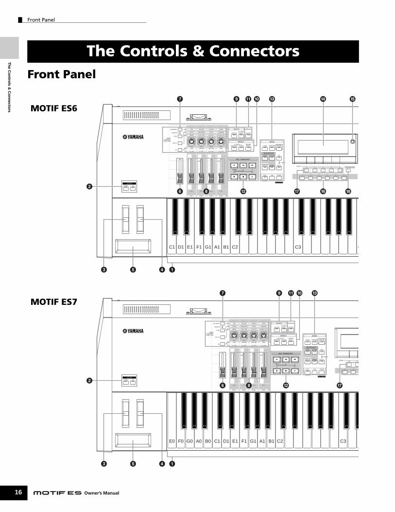
Front Panel................................................................... 16
Rear Panel .................................................................... 22
Setting Up ............................................. 26
Power Supply............................................................... 26
About data storage to SmartMedia cards and USB storage devices................................................... 27
Data lost and data retained when power is turned off........27Using the SmartMedia™ cards...........................................28Using USB storage devices................................................29
Connections................................................................. 31Connecting to External Audio Equipment...........................31Connecting External MIDI Instruments ...............................34Connecting to a Computer .................................................38Connecting Various Controllers ..........................................42
Turning the power on/off ............................................ 43Power-on Procedure ...........................................................43Turning the MOTIF ES on/off...............................................43
Resetting the User Memory to the Initial Factory Settings ........................................................................ 44
Basic Operation .................................... 45
Modes ........................................................................... 45Mode Structure ...................................................................45Mode table..........................................................................46
Functions and Sub-Functions.................................... 47
Selecting a Program.................................................... 47
Moving the Cursor and Setting Parameters.............. 49
Knob (KN) and Control Slider (CS) ............................ 50Knob (KN) ...........................................................................50Control Slider (CS) ..............................................................51
About the editing functions........................................ 51Edit Indicator.......................................................................51Compare Function ..............................................................52Edit Recall Function ............................................................52
Confirmation Message................................................ 52
Information Display..................................................... 53
Note (Key) settings...................................................... 53
Naming ......................................................................... 53
Owner’s Manual
Quick Guide — Playing the MOTIF ES .....55
Playing the Demo Songs/Patterns .............................55
Playing the Keyboard (in the Voice Play mode)........60Selecting a Voice ................................................................60Using Controllers ................................................................64Using the Arpeggio feature ................................................66
Playing the Keyboard (in the Performance Play mode) .....67Selecting a Performance ....................................................67Using Controllers ................................................................69Using the Arpeggio feature ................................................70Assigning desired Voices to each part...............................70Using the A/D input sound..................................................72
Using the Plug-in Board ..............................................74Available Plug-in Boards ....................................................74Using a Single Part Plug-in Board ......................................75Using a Multi Part Plug-in Board.........................................77Using an Effect Plug-in Board ............................................78
Quick Guide — Advanced Course ........79
Editing a Voice .............................................................79Normal Voice Edit ...............................................................79Drum Voice Edit ..................................................................82Plug-in Voice Edit................................................................85Storing/Saving the created Voice .......................................85
Editing a Performance.................................................87Storing/Saving the created Performance............................91
Creating a Voice by using the Sampling function ........94Sampling your voice with a microphone and creating a Normal Voice ...................................................................................94Sampling the sound of an audio device to create a Drum Voice ...........98
Creating a Song on the MOTIF ES............................102Recording your keyboard performance ...........................102Creating a Pattern.............................................................106Creating a Phrase by recording a rhythm pattern to a track .....106Using the Groove function ................................................114Creating a Section and Pattern Chain ..............................115Creating a Song................................................................117Storing/Saving the created Song/Pattern .........................131Storing the edited Song Mixing/Pattern Mixing settings to internal memory (DRAM) ................................................. 131
Using as a Master Keyboard.....................................136Selecting a Master ............................................................136Memorize to a Master .......................................................137Using Zones (keyboard area)...........................................137
Quick Guide — Computer applications....142
Setting up ...................................................................142
Controlling the instrument from a computer ..........143Using a sequencer to play multiple Voices on the MOTIF ES....143Using the Multi Part Editor to create/edit Mixing settings..........144Using the Voice Editor to create/edit a Voice ...................145Using the TWE Wave Editor to edit Samples....................146Controlling a computer from the instrument .....................147Setting up for Remote Control ..........................................148Functions assigned to the panel buttons in the Remote Control mode ............150

Table of Contents
he Controls & onnectors
etting Up
asic Operation
uick Guide — laying the MOTIF ES
uick Guide — dvanced Course
uick Guide — omputerplications
asic Structure
eferenceoice mode
erformance mode
ong mode
attern mode
ixing Voice mode
ampling mode
tility mode
ile mode
aster mode
ppendix
Basic Structure ....................................154
Internal Structure (System Overview)......................154Controller Block.................................................................154Tone Generator block .......................................................157Sequencer Block...............................................................165Sampling Block .................................................................172Effect Block .......................................................................177
About MIDI ..................................................................181MIDI channels ...................................................................181MIDI Messages Transmitted/Recognized by this synthesizer ...181
Internal Memory and File Management....................185Maintaining data ...............................................................185
Reference ............................................188
Voice mode.................................................................188Voice Play mode ...............................................................188Voice Edit mode................................................................189Voice Store mode..............................................................208Voice Job mode ................................................................208
Performance mode ....................................................212Performance Play mode....................................................212Performance Edit mode ....................................................213Performance Job mode ....................................................219Performance Store mode ..................................................220
Song mode..................................................................221Song Play mode................................................................221Song Record mode...........................................................222Song Edit mode ................................................................225Song Job mode.................................................................226Song Mixing mode ............................................................233Song Mixing Edit mode.....................................................234Song Mixing Job mode .....................................................236Song Mixing Store mode...................................................237
Pattern mode ..............................................................241Pattern Play mode.............................................................241Pattern Record mode........................................................243Pattern Edit mode .............................................................244Pattern Job mode..............................................................244Pattern Mixing mode .........................................................248Pattern Mixing Edit mode..................................................248Pattern Mixing Job mode ..................................................248Pattern Mixing Store mode................................................248
Mixing Voice mode.....................................................249Mixing Voice Edit mode ....................................................249Mixing Voice Store mode ..................................................250Mixing Voice Job mode ....................................................250
Sampling mode ..........................................................251Sampling Record mode ....................................................251Sampling Edit mode..........................................................255Sampling Job mode..........................................................256
Utility mode.................................................................260Utility mode .......................................................................260Utility Job mode ................................................................265
File mode ....................................................................266File mode ..........................................................................266
Master mode...............................................................271Master Play mode .............................................................271Master Edit mode..............................................................271Master Job mode ..............................................................273Master Store mode............................................................274
Appendix ............................................ 275
Information Displays ................................................. 275
Display Messages...................................................... 277
Troubleshooting ........................................................ 279
Installing Optional Hardware.................................... 282Available devices..............................................................282Installation locations..........................................................282Installation Precautions .....................................................282Optional Plug-in Board Installation ...................................283Installing the Plug-in Board...............................................283Optional AIEB2 or mLAN16E Installation ..........................285DIMM Installation ..............................................................289
Glossary ..................................................................... 290
Specifications ............................................................ 292
index ................................................... 294
TC
S
B
QP
QA
QCap
B
R V
P
S
P
M
S
U
F
M
A
15Owner’s Manual
Th
e Co
ntro
ls & C
on
necto
rs
Front Panel
16
Front Panel
The Controls & Connectors
DOWN UP
OCTAVE
SCENESF1 SF2
F1 F2
REMOTE ARPEGGIO
ON/OFF ON/OFFR-AUDIOG-MIDI
BYPASSINSERTION SYSTEM
MASTEREFFECT VOICE
SONG
PERFORM MASTER
PATTERN FILE
EFFECT MODE
SEQ TRANSPORT
SEQUENCER
LOCATE 1 2
INTEGRATEDSAMPLING MIXING UTILITY
EDIT
COMPARE SCENE STORESET LOCATE
JOB STORE
DEMO
KNOBCONTROLFUNCTION
MASTERVOLUME
ZONE 1
CS 1
VOLUME 1
SWING
CUTOFF
PAN
ASSIGN A
GATE TIME
RESONANCE
REVERB
ASSIGN B
VELOCITY
ATTACK
CHORUS
ASSIGN 1
UNITMULTIPLY
RELEASE
TEMPO
ASSIGN 2
LOW
KN 1
VOLUME 2
LOW MID
KN 2
VOLUME 3
HIGH MID
KN 3
VOLUME 4
HIGH
KN 4
CS 2
ZONE 2
CS 3
ZONE 3
CS 4
ZONE 4
ARP FX
EQ
TONE
ASSIGN
PAN/SEND
E0 F0 G0 A0 B0 C1 D1 E1 F1 G1 A1 B1 C2 C3
15
2
3 4
6 8
7 9 #! )
@ &
KNOBCONTROLFUNCTION
MASTERVOLUME
ZONE 1
CS 1
VOLUME 1
SWING
CUTOFF
PAN
ASSIGN A
GATE TIME
RESONANCE
REVERB
ASSIGN B
VELOCITY
ATTACK
CHORUS
ASSIGN 1
UNITMULTIPLY
RELEASE
TEMPO
ASSIGN 2
LOW
KN 1
VOLUME 2
LOW MID
KN 2
VOLUME 3
HIGH MID
KN 3
VOLUME 4
HIGH
KN 4
CS 2
ZONE 2
CS 3
ZONE 3
CS 4
ZONE 4
ARP FX
EQ
TONE
ASSIGN
PAN/SEND
SCENESF1 SF2 SF3 SF4 SF5
F1 F2 F3 F4 F5 F6
INFORMATION
REMOTE ARPEGGIO
ON/OFF ON/OFFR-AUDIOG-MIDI
BYPASSINSERTION SYSTEM
MASTEREFFECT VOICE
SONG
PERFORM MASTER
PATTERN FILE
EFFECT MODE
SEQ TRANSPORT
SEQUENCER
LOCATE 1 2
INTEGRATEDSAMPLING MIXING UTILITY
EDIT
COMPARE SCENE STORESET LOCATE
JOB STORE
DEMO
DOWN UP
OCTAVE
15
C1 D1 E1 F1 G1 A1 B1 C2 C3 C
3 4
6 8
7 9 # $ %! )
@ ^& *2
MOTIF ES6
MOTIF ES7
Owner’s Manual

Th
e C
on
tro
ls &
Co
nn
ecto
rs
Front Panel
F2 SF3 SF4 SF5
F3 F4 F5 F6
INFORMATION
COMMON ELEMENT/PERF. PART/ZONE
FAVORITES
DRUM KITS
A. PIANO KEYBOARD ORGAN
PRE 5 PRE 6
PRE 1 PRE 2 PRE 3 PRE 4MUSIC PRODUCTION SYNTHESIZERIntegrated Sampling Sequencer / Modular Synthesis Plug-in System / Real-time External Control Surface
USER 1
GUITAR/PLUCKED
SYN LEAD
A B C D E F G H
87654321
16 MUTE
TRACKSELECT
SECTION GROUP
NUMBER
CATEGORYSEARCH BANK
SOLO
151412 1311109
SYN PAD/CHOIR
SYN COMP CHROMATICPERCUSSION
DRUM/PERCUSSION
SE MUSICAL FX COMBI
USER 2
STRINGS
PLG 1
SLOT 1 SLOT 2 SLOT 3
BRASS
PLG 2
REED/PIPE
PLG 3
BASS
GM
EXIT ENTER
EXECUTE
DEC/NO INC / YES
C4 C5 C6
$ % (¡ º ∞
^ •¶* £ ¢™
§
ª
‚
⁄
¤
COMMON ELEMENT/PERF. PART/ZONE
FAVORITES
DRUM KITS
A. PIANO KEYBOARD ORGAN
PRE 5 PRE 6
PRE 1 PRE 2 PRE 3 PRE 4MUSIC PRODUCTION SYNTHESIZERIntegrated Sampling Sequencer / Modular Synthesis Plug-in System / Real-time External Control Surface
USER 1
GUITAR/PLUCKED
SYN LEAD
A B C D E F G H
87654321
16 MUTE
TRACKSELECT
SECTION GROUP
NUMBER
CATEGORYSEARCH BANK
SOLO
151412 1311109
SYN PAD/CHOIR
SYN COMP CHROMATICPERCUSSION
DRUM/PERCUSSION
SE MUSICAL FX COMBI
USER 2
STRINGS
PLG 1
SLOT 1 SLOT 2 SLOT 3
BRASS
PLG 2
REED/PIPE
PLG 3
BASS
GM
EXIT ENTER
EXECUTE
DEC/NO INC / YES
C4 C5 C6
(¡ º ∞
•¶£ ¢™
§
ª
‚
⁄
¤
n When both of the [OCTAVE] buttons are turned off, each key corresponds to the note name shown in the illustrations. Refer to this illustration when setting parameters having note name values, such as Note Limit.
17Owner’s Manual

Front Panel
18
Th
e Co
ntro
ls & C
on
necto
rs
1 Keyboard 4 Modulation wheel Page 64
REMOTE ARPEGGIO
ON/OFF ON/OFFR-AUDIOG-MIDI
BYPASSINSERTION SYSTEM
MASTEREFFECT VOICE
SONG
PERFORM MASTER
PATTERN FILE
EFFECT MODE
SEQ TRANSPORT
SEQUENCER
LOCATE 1 2
INTEGRATEDSAMPLING MIXING UTILITY
EDIT
COMPARE SCENE STORESET LOCATE
JOB STORE
DEMO
A-1 B-1 C0 D0 E0 F0 G0 H0 B0 C1 C2
KNOBCONTROLFUNCTION
MASTERVOLUME
ZONE 1
CS 1
VOLUME 1
SWING
CUTOFF
PAN
ASSIGN A
GATE TIME
RESONANCE
REVERB
ASSIGN B
VELOCITY
ATTACK
CHORUS
ASSIGN 1
UNITMULTIPLY
RELEASE
TEMPO
ASSIGN 2
LOW
KN 1
VOLUME 2
LOW MID
KN 2
VOLUME 3
HIGH MID
KN 3
VOLUME 4
HIGH
KN 4
CS 2
ZONE 2
CS 3
ZONE 3
CS 4
ZONE 4
ARP FX
EQ
TONE
ASSIGN
PAN/SEND
15
3
4
6 8
7 9 #! )
@
MOTIF ES8
The MOTIF ES6 features a 61-key keyboard, while the MOTIF ES7 has 76 keys and the MOTIF ES8 has 88 keys. All are equipped with a touch response feature (both initial touch and aftertouch). With initial touch, the instrument senses how strongly or softly you play the keys, and uses that playing strength to affect the sound in various ways, depending on the selected voice. With aftertouch, the instrument senses how much pressure you apply to the keys while playing, and uses that pressure to affect the sound in various ways, depending on the selected voice. Moreover, any of a variety of functions can be assigned to aftertouch for each voice.
2 OCTAVE [UP] and [DOWN] buttons Page 63Use these buttons to change the note range of the keyboard. To restore the normal octave setting, press both buttons simultaneously.
n Because of its extended keyboard, the MOTIF ES8 does not have OCTAVE buttons.
3 Pitch bend wheel Page 64Controls the pitch bend effect. You can also assign other functions to this controller.
Owner’s Manual
Controls the modulation effect. You can also assign other functions to this controller.
5 Ribbon controller Page 65This Controller is touch sensitive, and is controlled by running your finger lightly across its surface laterally. You can also assign other functions to this controller.
6 MASTER VOLUMEAdjusts the volume of the overall sound, as output from the rear-panel OUTPUT L/MONO and R jacks as well as the PHONES jack.
7 Four KNOB CONTROL FUNCTION buttons and four Knobs Page 50These four highly versatile knobs let you adjust various aspects or parameters of the current Voice. Use the [KNOB CONTROL FUNCTION] buttons to change the parameter set for the knobs. The corresponding LED lights to indicate which group of parameters are active.

Front Panel
Th
e C
on
tro
ls &
Co
nn
ecto
rs
8 [CS1] - [CS4] (Control Slider) Page 51 ) EFFECT buttons Page 147
REE
SCENESF1 SF2 SF3 SF4 SF5
F1 F2 F3 F4 F5 F6
COMMON ELEMENT/PERF. PART/ZONE
FAVORITES
DRUM KITS
A. PIANO KEYBOARD ORGAN
PRE 5 PRE 6
PRE 1 PRE 2 PRE 3 PRE 4MUSIC PRODUCTION SYNTHESIZERIntegrated Sampling Sequencer / Modular Synthesis Plug-in System / Real-time External Control Surface
USER 1
GUITAR/PLUCKED
SYN LEAD
A B C D E F G H
87654321
16 MUTE
TRACKSELECT
SECTION GROUP
NUMBER
CATEGORYSEARCH BANK
SOLO
151412 1311109
SYN PAD/CHOIR
SYN COMP CHROMATICPERCUSSION
DRUM/PERCUSSION
SE MUSICAL FX COMBI
USER 2
STRINGS
PLG 1
SLOT 1 SLOT 2 SLOT 3
BRASS
PLG 2
REED/PIPE
PLG 3
BASS
GM
INFORMATION
DEMO
EXIT ENTER
EXECUTE
DEC/NO INC / YES
C3 C4 C5 C6 C7
$ % (¡ º ∞
^ •& ¶* £ ¢™
§
ª
‚
⁄
¤
n When [UTILITY] → [F1] GENERAL → [SF2] KBD → Octave is set to “0,” each key corresponds to the note name shown in the illustrations. Refer to this illustration when setting a note name of a parameter like Note Limit.
These sliders control the volume of four elements which make up a Normal Voice in the Voice mode, the volume of four parts in the Performance mode, the volume of four parts including the current part in the Song mode/Pattern mode, and the volume of four zones in the Master mode.
n If all of the Control Sliders are set to the minimum, you may not hear any sound from the instrument, even when playing the keyboard or a song/pattern. If this is the case, raise all the sliders to a suitable level.
n The [MASTER VOLUME] slider adjusts the output level from this instrument. On the other hand, the Control Slider adjusts the MIDI volume value for the corresponding element or part.
9 REMOTE buttons Page 147The Remote mode lets you control sequencer software on your computer from the panel controls of the instrument. Turn the [ON/OFF] button on to enter the Remote mode. You can use the [R-AUDIO/G-MIDI] button to switch control between your audio tracks (red lamp) and MIDI tracks (green lamp), when Mode A or B is set to “General” ([UTILITY] → [F4] CTL ASN → [SF4] REMOTE).
n When setting the MIDI IN/OUT parameter to “MIDI” ([UTILITY] → [F5] MIDI → [SF4] OTHER) or setting both of Mode A and Mode B to “off” ([UTILITY] → [F4] CTL ASN → [SF4] REMOTE), you cannot enter the Remote mode even by pressing the REMOTE [ON/OFF] button. Set these parameters to appropriate values (page 148) then enter the Remote mode.
The extensive effect section of the instrument provides Insertion effects (eight sets, with two effect units per set), System effects (Reverb and Chorus), and Master effects. The effects can be applied to the keyboard-played voices and to Song/Pattern playback. These three buttons enable you to turn the corresponding Effect blocks (as printed on the panel) on or off with a single touch. Keep in mind that the [INSERTION] and [SYSTEM] buttons are bypass switches, while the [MASTER EFFECT] button is an on/off switch. The distinction is important — when the lamp of the [INSERTION] or [SYSTEM] button is on, the effect is off (or bypassed). The [MASTER EFFECT] button is the opposite: when the lamp is on, the Master effect is on. Also, to access the Master Effect setting display, press and hold the [MASTER EFFECT] button for a second or two.
! [ARPEGGIO ON/OFF] button Page 66Press this button to enable or disable playback of the Arpeggio for each Voice, Performance, Song, or Pattern. If the Arpeggio Switch of the selected part is set to off in the Performance/Song/Pattern mode, however, pressing this button has no effect.
19Owner’s Manual

Front Panel
20
Th
e Co
ntro
ls & C
on
necto
rs
@ SEQ TRANSPORT buttons Page 56These buttons control recording and playback of the Song/Pattern sequence data.
[ ](Top) buttonInstantly returns to the beginning of the current song or pattern (i.e., the first beat of the first measure).
[ ](Reverse) buttonPress briefly to move back one measure at a time, or hold to continuously rewind.
[ ](Forward) buttonPress briefly to move forward one measure at a time, or hold to continuously fast-forward.
[● ] (Record) buttonPress this to enable recording (Song or pattern phrase). (The indicator lights.)
[ ](Stop) buttonPress to stop recording or playback.
[ ](Play) buttonPress to start playback from the current point in the song or pattern. During recording and playback, the indicator flashes at the current tempo.
# MODE buttons Page 45These buttons select the operating modes (e.g., Voice mode).
$ LCD DisplayThe large backlit LCD displays the parameters and values related to the currently selected operation or mode.
% LCD Contrast Control Page 43Use this control to set the LCD display for optimum legibility.
^ [F1] - [F6] (Function) buttons Page 47These buttons located directly below the LCD display call up the corresponding functions indicated in the display. In the display hierarchy, these functions [F] rank just below the modes.
& [SF1] - [SF5] (Sub Function) buttons Page 47These buttons located directly below the LCD display call up the corresponding sub functions indicated in the display. In the display hierarchy, these sub functions [SF] rank just below the functions [F].These buttons can be also used to store/recall the Arpeggio type in each Play mode and Song/Pattern Record mode. They can be also used to store/recall the Song Scene (page 123) in the Song Play/Song Record/Pattern Chain Record modes.
Owner’s Manual
* [INFORMATION] button Page 53For calling up a special “help” feature that shows information about the currently selected mode. You can go back to the previous display by pressing this button again or pressing any other button.Depending on the selected display, this button may be used to call up a window for inputting characters (page 54), for inputting numbers (page 49), for selecting note lengths (page 49), or for selecting keys or note names (page 53).
( Data dial Page 49For editing the currently selected parameter. To increase the value, turn the dial right (clockwise); to decrease the value, turn the dial left (counter-clockwise). If a parameter with a wide value range is selected, you can change the value in broader strokes by quickly turning the dial.
º [INC/YES] button Page 49For increasing the value of the currently selected parameter. Also use it to actually execute a Job or a Store operation.
¡ [DEC/NO] button Page 49For decreasing the value of the currently selected parameter. Also use it to cancel a Job or a Store operation.
n You can also use the [INC/YES] and [DEC/NO] buttons to quickly
move through parameter values in 10-unit jumps, especially those with large ranges. Simply hold down one of the buttons (of the direction you want to jump), and simultaneously press the other. For example, to jump in the positive direction, hold down the [INC/YES] button and press [DEC/NO].
™ Cursor Buttons Page 49The cursor buttons move the “cursor” around the LCD display screen, highlighting and selecting the various parameters.
£ [EXIT] button Page 46The menus and displays of this synthesizer are organized according to a hierarchical structure.Press this button to exit from the current display and return to the previous level in the hierarchy.
¢ [ENTER] buttonUse this button to execute a Job or a Store operation. Also use this button to actually enter a number when selecting a Memory or Bank for Voice or Performance. In the File mode, use this button to go to the next lowest level in the selected directory.

Front Panel
Th
e C
on
tro
ls &
Co
nn
ecto
rs
∞ SLOT 1-3 lamps Page 284These three lamps show the installation status of the Plug-in Boards.If the Plug-in Board has been correctly installed, the corresponding SLOT lamp will light.
n The Vocal Harmony Plug-in Board (PLG100-VH) can be installed only to slot 1. It cannot be installed to slot 2 or 3.
n The Multi part Plug-in Board (PLG100-XG) can be installed only to slot 3. It cannot be installed to slot 1 or 2.
§ BANK buttons Page 60Each button selects a Voice or Performance Bank.When the [CATEGORY SEARCH] button is turned on, these buttons can be used to select the desired category (printed below each button). When the [SECTION] button is turned on in the Pattern mode, these buttons are used to select the desired section.
¶ GROUP [A] - [H] buttons Page 48Each button selects a Voice or Performance Group.When the [CATEGORY SEARCH] button is turned on, these buttons can be used to select the desired category (printed below each button). When the [SECTION] button is turned on in the Pattern mode, these buttons are used to select the desired section.
• NUMBER [1] - [16] buttons Page 48Use of these buttons differs depending on the on/off status of the [TRACK SELECT] and [MUTE] buttons.
Functions of the NUMBER [1] - [16] buttons
When [TRACK SELECT] is on
When [MUTE] is on
When both [TRACK SELECT] [MUTE] are off
Voice Play modeKeyboard transmit channel setting
—Voice selection, according to Groups A - H
Voice Edit mode Element selection (1 - 4) and Element Mute setting (9 - 12) —
Performance Play mode
Keyboard transmit channel setting Performance part
Mute setting (1 - 4)
Performance or Voice selection(if cursor is located at Voice name), according to Groups A - H
Performance Edit mode
Performance part selection (1 - 4)
Master Play mode
Keyboard transmit channel setting (when memorizing the Voice mode or Performance mode to the current Master) or Song/Pattern track selection (when memorizing the Song mode or Pattern mode to the current Master)
—Master selection, according to Groups A - H
Master Edit mode
Zone selection (1 - 4) — —
Song/Pattern Play mode
Song/Pattern track selection
Song/Pattern track Mute setting
Song/Pattern selection, according to Groups A - HSong/Pattern
Mixing modeSong/Pattern part selection
Song/Pattern part Mute setting
Mixing Voice Edit mode
Element selection (1- 4) and Element Mute setting (9- 12) —
ª [CATEGORY SEARCH] button Page 62When this button is turned on in the Performance mode, the lower row of [BANK] buttons (labeled A.PIANO - REED/PIPE below the buttons) and the [GROUP] buttons can be used to select the Performance category.When this button is turned on in another mode, the lower row of [BANK] buttons (labeled A.PIANO - REED/PIPE below the buttons) and the [GROUP] buttons can be used to select the Voice category.
‚ [SECTION] button Page 56When this button is turned on in the Pattern mode, the GROUP [A] - [H] buttons can be used to select Pattern Sections A - H and the [PRE5] - [PLG3] buttons of the BANK buttons can be used to select Pattern Sections I - P.
⁄ [TRACK SELECT] button Page 58Turning this button on in the Song/Pattern mode enables the NUMBER [1] - [16] buttons for selecting corresponding Song/Pattern tracks. The on/off status of this button affects the NUMBER [1] - [16] buttons in different ways, depending on the selected mode. (See • “NUMBER [1] - [16] buttons” above.)
¤ [MUTE] button Page 58Turning this button on in the Song/Pattern mode enables the NUMBER [1] - [16] buttons for muting corresponding Song/Pattern tracks.Press one of the NUMBER [1] - [16] buttons while holding this button to solo the corresponding track of the current selected Song/Pattern.The on/off status of this button affects the NUMBER [1] - [16] buttons in different ways, depending on the selected mode. (See • “NUMBER [1] - [16] buttons” above.)
21Owner’s Manual

Th
e Co
ntro
ls & C
on
necto
rs
Rear Panel
22
Rear Panel
BREATH ASSIGOUTTHRU
USB
TO HOSTTO DEVICEmLAN I/O EXPANSIONAC INLETPOWER
ON OFF INMIDI
1 2 3 4 65
mLAN I/O EXPANSIONAC INLETPOWER
ON OFF
1 2 3
mLAN I/O EXPANSIONAC INLETPOWER
ON OFF
1 2 3
MOTIF ES6
MOTIF ES7
MOTIF ES8
Owner’s Manual

Th
e C
on
tro
ls &
Co
nn
ecto
rs
Rear Panel
GREENYELLOWORANGEPlug-in SLOT
A /D INPUTLR
OUTPUTR L/MONO PHONES
ASSIGNABLE OUTPUTLR
FOOTCONTROLLER
ASSIGNABLE SUSTAIN
FOOTSWITCH
CARD3.3V
12GAIN
! #7 8 9 ) @
$ %
GREENYELLOWORANGEPlug-in SLOT
A /D INPUTLR
OUTPUTR L/MONO PHONES
ASSIGNABLE OUTPUTLR
FOOTCONTROLLER
BREATH ASSIGNABLE SUSTAINOUTTHRU
USB
TO HOSTTO DEVICE
FOOTSWITCH
CARD3.3V
1INMIDI
2GAIN
4 6 ! #5 7 8 9 ) @
$ %
CARD3.3V
USB
TO HOSTTO DEVICE
GREENYELLOWORANGEPlug-in SLOT
A /D INPUTLR
OUTPUTR L/MONO PHONES
ASSIGNABLE OUTPUTLR
GAIN
FOOTCONTROLLER
BREATH ASSIGNABLE SUSTAINOUTTHRU
FOOTSWITCH
1INMIDI
2
4 6 ! #5% 7 8 9 ) @
$
23Owner’s Manual

Rear Panel
24
Th
e Co
ntro
ls & C
on
necto
rs
1 POWER Switch Page 43Press to turn power ON or OFF.
2 AC INLET (AC Power Cord Socket) Page 26Be sure to plug the AC power cord into this socket before plugging the power cord into an AC outlet.Use only the AC power cord supplied with this instrument. If the supplied cord is lost or damaged and needs to be replaced, contact your Yamaha dealer.The use of an inappropriate replacement can pose a fire and shock hazard!
3 mLAN expansion board (mLAN16E) or I/O expansion board (AIEB2) cover Page 25Either the mLAN expansion board (mLAN16E) or the I/O expansion board (AIEB2) sold separately can be installed to this instrument. With the mLAN16E board, you can conveniently and easily hook up your MOTIF ES to other mLAN compatible instruments or devices. The AIEB2 board gives you additional digital I/O options, featuring both optical and coaxial connectors. Moreover, the board also includes three stereo ASSIGNABLE OUTPUT pairs (six analog jacks).
4 USB connectors Page 29This instrument is equipped with two types of USB connectors on the rear panel – USB TO HOST and USB TO DEVICE. The USB TO HOST connector is used to connect this instrument to the computer via the USB cable. The USB connection between the instrument and the computer can only be used for transfer of MIDI data. No audio data can be transferred via USB. The USB TO DEVICE connector is used to connect this instrument to a USB storage device (hard disk drive, CD-ROM drive, MO drive, flash disk, etc.) via the USB cable. This lets you save the data created on this instrument to the external USB storage device and load the data from the external USB storage device to the instrument. Save/Load operations can be performed in the File mode.
n For details about USB, see page 29.
5 MIDI IN/OUT/THRU connectors Page 34MIDI IN is for receiving control or performance data from another MIDI device, such as an external sequencer.MIDI THRU is simply for redirecting any received MIDI data (via MIDI IN) to connected devices, allowing convenient chaining of additional MIDI instruments.MIDI OUT is for transmitting all control, performance and playback data from the MOTIF to another MIDI device, such as an external sequencer.
USB
USB is an abbreviation for Universal Serial Bus. It is a serial interface for connecting a computer with peripheral devices, and enables much faster data transfer compared to conventional serial port connections.
Owner’s Manual
6 BREATH Controller Jack Page 42Connect an optional Yamaha BC3 Breath Controller here for expressive breath control capability.
7 FOOT SWITCH jacks Page 42For connection of optional FC4 or FC5 Footswitches. When connected to the SUSTAIN jack, the Footswitch controls sustain. When connected to ASSIGNABLE, it can control one of various different assignable functions.
8 FOOT CONTROLLER jacks Page 42For connection of optional foot controllers (FC7, etc.). Each jack lets you continuously control one of various different assignable functions – such as volume, tone, pitch, or other aspects of the sound.
9 ASSIGNABLE OUT L and R jacks Page 31Line level audio signals are output from this instrument via these phone jacks (1/4" mono phone plug).These outputs are independent of the main output (at the L/MONO and R jacks below), and can be freely assigned to any of the Drum Voice keys or the Parts. This lets you route specific Voices or sounds for processing with a favorite outboard effect unit.
The parts which can be assigned to these jacks are as follows:
• Drum Voice key to which the drum/percussioninstrument is assigned Page 203
• Any part of a Performance* Page 219• Any part of a Song* Page 235• Any part of a Pattern* Page 235
* Including the Audio Input part
) OUTPUT L/MONO and R jacks Page 31Line level audio signals are output via these phone jacks. For monophonic output, use just the L/MONO jack.
! PHONES jack Page 31For connection to a pair of stereo headphones.
@ A/D INPUT jacks Page 33External audio signals can be input via these phone jacks (1/4" mono phone plug). Various devices such as microphone, guitar, bass, CD player, synthesizer can be connected to these jacks and their audio input signal can be sounded as the AUDIO IN part of the Performance, Song, or Pattern.In the Sampling mode, these jacks are used for capturing audio data as samples. For stereo signals (such as from audio equipment), use both jacks. For mono signals (such as from a microphone or guitar), use only the L jack.

Rear Panel
Th
e C
on
tro
ls &
Co
nn
ecto
rs
# GAIN knob Page 73For adjusting the input gain of the audio at the A/D INPUT jacks (above). Depending on the connected device (microphone, CD player, etc.), you may need to adjust this for optimum level.
$ CARD (Card slot) Page 27Insert a SmartMedia (memory) card here to transfer various data to/from this instrument. Read carefully the precautions on using a SmartMedia (page 28) before inserting a SmartMedia card.
% Plug-in board cover Page 283Installing an optional Plug-in Board to this instrument lets you greatly expand the sonic palette of the instrument. Up to three boards can be installed to the rear panel.
■ When the optional mLAN16E has been installed:
1 mLAN (IEEE1394) connector 1, 2For connecting mLAN devices or IEEE1394-compatible (FireWire) devices via standard IEEE1394 (6-pin) cables.
* The name “mLAN” and its logo (above) are trademarks.
n The digital audio output via the mLAN connector is fixed to a resolution of 24 bit/44.1 kHz.
About mLAN
“mLAN” is a digital network designed for musical applications.It uses and extends the industry standard IEEE 1394 high performance serial bus.For details, refer to the Guide Book of the mLAN16E.
mLAN EXPANSION BOARD mLAN16E
ACTIVEMADE IN JAPAN
IEEE13942 1
1
■ When the optional AIEB2 has been installed:
1 OPTICAL IN, OUT connectors Pages 33, 34Use these connectors to input or output digital signals over optical-fiber cable. You can use the OPTICAL IN to record a digital signal at frequencies of 48kHz, 44.1kHz, or 32kHz. The OPTICAL OUT connector outputs a digital signal of 44.1kHz.
2 DIGITAL IN, OUT connectors Pages 33, 34Use these connectors to input or output digital signals over coaxial (RCA-pin) cable. The digital signal format is CD/DAT (S/P DIF). You can use the DIGITAL IN connector to record a digital signal at frequencies of 48kHz, 44.1kHz, or 32kHz. The DIGITAL OUT connector outputs a digital signal of 44.1kHz.
3 ASSIGNABLE OUT jacks (AS1 to AS6) Page 31Line level audio signals are output from this instrument via these phone jacks (1/4" mono phone plug).These outputs are independent of the main output (at the L/MONO and R jacks above), and can be freely assigned to any of the Drum Voice key or the Parts. This lets you route specific Voices or sounds for processing with your favorite outboard effect unit.
The parts which can be assigned to these jacks are as follows:
• Drum Voice key to which the drum/percussion instrument is assigned Page 203
• Any part of a Performance* Page 219• Any part of a Song* Page 235• Any part of a Pattern* Page 235
* Including the Audio Input part
n Digital audio output via the OPTICAL OUT connector or DIGITAL OUT connector can be changed between 20-bit and 24-bit resolution in the [UTILITY] → [F2] I/O → [SF2] OUTPUT display. The frequency, however, is fixed at 44.1 kHz.
1 2 3
25Owner’s Manual

Settin
g U
p
Power Supply
26
Please read this section carefully before using your new MOTIF ES.This section explains how to connect your MOTIF ES to an AC power source, external audio and MIDI devices, and a computer system. Only switch the MOTIF ES on after you have made all the necessary connections (page 43).
Power Supply
1 Make sure the POWER switch on the MOTIF ES is set to OFF.
2 Connect the supplied power cord to the AC INLET on the instrument’s rear panel.
3 Connect the other end of the power cord to an AC outlet. Make sure your MOTIF ES meets the voltage requirement for the country or region in which it is being used.
Make sure your MOTIF ES is rated for the AC voltage supplied in the area in which it is to be used (as listed on the rear panel). Connecting the unit to the wrong AC supply can cause serious damage to the internal circuitry and may even pose a shock hazard!
Use only the AC power cord supplied with the MOTIF ES. If the supplied cord is lost or damaged and needs to be replaced, contact your Yamaha dealer. The use of an inappropriate replacement can pose a fire and shock hazard!
The type of AC power cord provided with the MOTIF ES may be different depending on the country in which it is purchased (a third prong may be provided for grounding purposes). Improper connection of the grounding conductor can create the risk of electrical shock. Do NOT modify the plug provided with the MOTIF ES. If the plug will not fit the outlet, have a proper outlet installed by a qualified electrician. Do not use a plug adapter which defeats the grounding conductor.
Setting Up
Rear panel
AC INLET
Power cord (included)
WARNING
WARNING
WARNING
Owner’s Manual

Set
tin
g U
p
About data storage to SmartMedia cards and USB storage devices
About data storage to SmartMedia cards and USB storage devicesAs you make music with this instrument, you’ll create a wide variety of data — such as custom Voice data (including Voices, Performances, etc.), MIDI sequence data (Songs, Patterns, Arpeggios), and waveform data (with the Sampling function). Naturally, you’ll want to store this data for safekeeping and future use, and the instrument is equipped with a variety of storage options. You can save your data to SmartMedia card (inserted to the Card slot) or to a USB storage device (connected to the USB TO DEVICE connector). To recall the data, use the Load function. (Save and Load operations are done in the File mode; see page 266.)Keep in mind that certain types of data are lost when you turn off the power and should be properly saved. Also keep in mind that since there are several storage options (including SmartMedia card, hard disk, flash disk, etc.), you should always have the proper media formatted and on hand BEFORE you start creating or editing data.
n The Save/Load operation in the File mode can be executed between the SmartMedia card inserted to the CARD slot on the rear panel and the instrument, or between the USB storage device connected to the USB TO DEVICE connector and the instrument. Please keep in mind that the Save /Load operation in the File mode cannot be executed between the SmartMedia card inserted to the CARD slot on the rear panel and the USB storage device connected to the USB TO DEVICE connector. In short, data can be saved/loaded between the storage media and the instrument, but not between the two storage media devices.
Data lost and data retained when power is turned off
The chart below lists the data types you can create on the instrument and the internal memory locations to which they are stored, permanently or temporarily.
Make sure to save any data remaining in DRAM to SmartMedia or a USB storage device before turning off the power, other wise the data will be lost.
* Includes the Mixing settings (pages 103, 127)
** If you create the User Voices or Sample Voices by using the Sampling function, the corresponding Waveforms can be saved automatically by saving the User Voice data or Song/Pattern data to the SmartMedia/USB storage device.
*** Song Mixing/Pattern Mixing can be stored as Song/Pattern data and as a Mixing Template (which are not associated with a specific Song/Pattern).
n For details about the data types you can create on this instrument, the internal memory locations to which they are stored, and file types when saving the created data to the SmartMedia/USB storage device, refer to “Memory Structure” on page 186.
Data of up to 128 MB can be saved to a SmartMedia card inserted to the CARD slot on the rear panel. Yamaha recommends the use of a large-capacity USB storage device, since you may want to save data more 128 MB — especially if you’ve installied optional DIMMs (page 289) and are using the Sampling feature.
Data types Page Mode in which data is created Internal memory types to which data is stored
Voice 79 Voice mode Flash ROM
Mixing Voice 105 Mixing Voice mode DRAM ➜ Will be lost when turning the power off!
Performance 87 Performance mode Flash ROM
Song* 117 Song mode DRAM ➜ Will be lost when turning the power off!
Song Chain 59 Song Chain mode DRAM ➜ Will be lost when turning the power off!
Pattern* 106 Pattern mode DRAM ➜ Will be lost when turning the power off!
Pattern Chain 115 Pattern Chain mode DRAM ➜ Will be lost when turning the power off!
Phrase (Pattern) 110 Pattern mode DRAM ➜ Will be lost when turning the power off!
Arpeggio 130 Song mode, Pattern mode Flash ROM
Master 136 Master mode Flash ROM
Waveform** 94 Sampling mode DIMM (DRAM) ➜ Will be lost when turning the power off!
Mixing Template*** 103 Song Mixing mode, Pattern Mixing mode Flash ROM
System settings 185 Utility mode Flash ROM
MUSIC PRODUCTION SYNTHESIZER
MOTIF ES
SmartMedia (page 28)
USB TO DEVICE connector
USB storage device (page 29)
CAUTION
CAUTION
27Owner’s Manual

About data storage to SmartMedia cards and USB storage devices
28
Settin
g U
p
Using the SmartMedia™* cards
Be sure to handle SmartMedia cards with care. Follow the important precautions below.
* SmartMedia is a trademark of Toshiba Corporation.
■ Compatible Memory Card Type3.3V (3V) Memory Cards can be used. 5V type Memory Cards are not compatible with this instrument.
■ Memory CapacityThere are seven types of Memory Cards: 2MB/4MB/8MB/16MB/32MB/64MB/128MB. Keep in mind that only SmartMedia cards conforming to SSFDC standards (bearing the SmartMedia logo) can be used.
■ Inserting/Removing SmartMedia cards
Inserting a SmartMedia cardWith the gold-plated contact side facing down, insert the SmartMedia card firmly but carefully into the card slot, as far as it will go. Be careful not to insert the card upside down or back side in. Also, do not insert anything else into the slot, other than a proper SmartMedia card.
Removing a SmartMedia cardBefore removing the Memory Card, be sure to confirm that the Memory Card is not in use, or it is not being accessed by the instrument. Then pull the Memory Card out slowly by hand. If the Memory Card is being accessed*, a message indicating that it is in use appears on the instrument’s display.
* This includes all save, load, format, delete and create directory operations for the SmartMedia card. Also, be aware that the instrument will automatically access the Memory Card to check the media type when it is inserted while the instrument is turned on.
Never attempt to remove the Memory Card or turn the power off during accessing. Doing so can damage the data on the instrument/Memory Card and possibly the Memory Card itself.
■ Formatting Memory CardsBefore using a Memory Card with your instrument it must first be formatted. Once it is formatted all data on it will be erased. Make sure that no important data is contained on the card beforehand.
n The SmartMedia cards formatted with this instrument may be unusable with other instruments or devices.
CAUTION
Owner’s Manual
■ About the SmartMedia cards
Handle SmartMedia cards with care!• SmartMedia cards are very sensitive and can be damaged
by static electricity. Before handling a SmartMedia card, make sure to discharge any static electricityin your body by touching something made of metal, such as a door knob or aluminum blinds.
• Be sure to remove the Memory Card from the Memory Card slot when it is not in use for a long time.
• Do not expose the Memory Card to direct sunlight, extremely high or low temperatures, or excessive humidity, dust or liquids.
• Do not place heavy objects on a Memory Card or bend or apply pressure to the Memory Card in any way.
• Never touch the gold-plated contact with your fingers or let it come in contact with any other metallic or hard surface.
• Do not expose the Memory Card to magnetic fields, such as those produced by televisions, speakers, motors, etc., since magnetic fields can partially or completely erase data on the Memory Card, rendering it unreadable.
• Do not attach anything other than the provided labels to a Memory Card. Also make sure that labels are attached in the proper location.
Protecting your data (write-protect)To prevent important data from being inadvertently erased, apply the write-protect seal (provided with the SmartMedia card) to the circle spot indicated on the card. If you are saving data to the card, make sure to remove the write-protect seal. Do not reuse a seal that has been removed; it may not stick properly to the card and could come off in the slot.
■ Data BackupFor maximum data security Yamaha recommends that you keep two copies of important data on separate Memory Cards. This gives you a backup if one Memory Card is lost or damaged.
■ Burglarproof LockThis instrument is equipped with a burglarproof lock for the Memory Card. If necessity arises, install the burglarproof lock onto the instrument.
To install the burglarproof lock:
1 Remove the metallic part using a Phillips screwdriver.
2 Turn the metallic part upside down and replace it in the new position.

About data storage to SmartMedia cards and USB storage devices
Using USB storage devices
When using USB storage devices, make sure to connect them to the USB TO DEVICE connector, and follow the important precautions below.
Set
tin
g U
p
■ Compatible USB devicesConnect only a USB storage device (such as hard disk, CD-ROM, flash disk and other drives) to the USB TO DEVICE connector. Other devices such as a computer keyboard or mouse cannot be used.Both bus-powered (powered by the host device) or self-powered (battery or external power supply) types can be used.
The MOTIF ES does not necessarily support all commercially available USB storage devices. Yamaha cannot guarantee operation of USB storage devices that you purchase. Before purchasing USB storage devices, please consult your Yamaha dealer, or an authorized Yamaha distributor (see list at end of the Owner’s Manual) for advice, or see the following page: http://www.yamahasynth.com/
n Although CD-R/W drives can be used to load data to the instrument, they cannot be used for saving data. However, you can transfer data to a computer and save data to a CD using the CD-R/W drive on the computer.
■ Formatting USB storage mediaWhen a USB storage device is connected or media is inserted, a “Disk or card unformatted” message may appear in the LCD display, indicating that the device or media must be formatted for use. Execute the Format operation in the File mode (page 268).
■ Protecting your data (write-protect)To prevent important data from being inadvertently erased, apply the write-protect provided with each storage device or media. If you are saving data to the USB storage device, make sure to remove the write-protect.
Precautions when using the USB TO DEVICE connector
• Never turn the USB device’s power on/off and never plug/unplug the USB cable when the connected USB storage device is the self-powered type. Doing so may result in the operation of the synthesizer “freezing” or hanging up.
• While the instrument is accessing data (such as in the Save, Load and Delete operations in the File mode), do NOT unplug the USB cable, do NOT remove the media from the device, and do NOT turn the power off to either device. Doing so may corrupt the data on either or both devices.
CAUTION
USB connector typesThere are two different types of USB connectors, and the rear panel of the instrument features both. Take care not to confuse the two.
■ USB TO HOST connectorThis type is used to connect the instrument to a computer, and allows you to transfer MIDI data between the devices. Unlike MIDI, USB can handle multiple ports via a single cable.USB cables have different connectors on each end: the A type and the B type. Connect the A type to your computer and the B type to the USB TO HOST connector.
■ USB TO DEVICE connectorThis type is used to connect the instrument to a USB storage device, and allows you to save data you’ve created to the connected device, as well as load data from the connected device. Save and Load operations are executed in the File mode.USB cables have different connectors on each end: the A type and the B type. Connect the A type to the USB TO HOST connector and the B type to the USB storage device.
n The computer cannot access the USB storage device connected to the MOTIF ES’s USB TO DEVICE connector, even if connecting as shown above. Only from the File mode on the instrument itself can you access the data on the USB storage device connected to the USB TO DEVICE connector.
n Though the MOTIF ES supports the USB 1.1 standard, you can connect and use a USB 2.0 storage device with the MOTIF ES. However, note that the transfer speed complies to USB 1.1.
MOTIF ES
MUSIC PRODUCTION SYNTHESIZER
MIDI data transfer
Connecting to a computer
Connecting to a USB storage device (hard disk, CD-ROM, flash disk and other drives)
Saving/Loading data in the File mode (page 266)
A typeB type
USB TO DEVICE connector
USB TO HOST connector
29Owner’s Manual

About data storage to SmartMedia cards and USB storage devices
30
Settin
g U
p
Basic settings for using SmartMedia or a USB storage device
1 Press the [FILE] button to enter the File mode.
2 Press the [SF1] CURRENT button to check which device is selected.
When Current is set to “CARD”The instrument recognizes the SmartMedia inserted to the Card slot.
When Current is set to “USB”The instrument recognizes the USB storage device.
Volume Label of the selected device
Owner’s Manual
3 Set Current to “CARD” if you wish to access the SmartMedia, or set Current to “USB” if you wish to access the USB storage device.
If the USB storage device supports multiple types of media, you’ll need to set the Slot number after setting Current to “USB.” To check which media corresponds to which USB number (1 or 2) and which slot number, see the Volume Label or Partition setting in this window.
Once you’ve made the settings above, you can perform any of the other File operations (in the bottom tabs, called up with the [F2] - [F5] buttons).
n When a USB storage device is connected or media is inserted, a “Disk or card unformatted” message may appear in the LCD display, indicating that the device or media must be formatted for use. Execute the Format operation in the File mode (page 268).
Backing up your data to a computer
• Backing up MOTIF ES data to a computerOnce you’ve saved data to a SmartMedia card or USB storage device, you can copy the data to the hard disk of your computer, then archive and organize the files as desired. Simply reconnect the device as shown below.
n Though the example here shows the use of a connected USB storage device, you can also back up your created data that you’ve saved to a SmartMedia inserted to the CARD slot on the rear panel.
TIP
MUSIC PRODUCTION SYNTHESIZER
MOTIF ES
MUSIC PRODUCTION SYNTHESIZER
MOTIF ES
Saving created data to the USB storage device in the File mode (page 266)
Computer
USB storage device
USB TO DEVICE connector
Disconnect the USB storage device from the synthesizer and connect it to the computer
Backing up data to a computer and organizing files/folders
ComputerUSB storage device
• Loading data from a computer to the MOTIF ESData and files contained on the hard disk of a computer can be loaded to the MOTIF ES by copying them first to the storage media, then transferring them to the instrument.In this way, you can use data created on the computer or another instrument with the MOTIF ES. For example, you can load Standard MIDI files to the instrument as Song/Pattern data, or import audio WAV or AIFF files for use as waveform data.
MUSIC PRODUCTION SYNTHESIZER
MOTIF ES
MUSIC PRODUCTION SYNTHESIZER
MOTIF ES
ComputerUSB storage device
Computer
USB storage device
Copying the files of the hard disk of the computer to the USB storage device
Disconnect the USB storage device from the computer and connect it to the synthesizer
Loading files on the USB storage device to the synthesizer in the File mode (page 266)
USB TO DEVICE connector

Set
tin
g U
p
Connections
Connections
Connecting to External Audio Equipment
Since the MOTIF ES has no built-in speakers, you’ll need an external audio system or a set of stereo headphones to properly monitor it. The following illustrations show various connection examples; use the one most similar to your intended setup.
Audio Output
■ Connecting stereo powered speakers (analog output)For optimum, accurate reproduction of the instrument’s rich sounds, effects and full stereo image, use a pair of powered speakers. Connect the powered speakers to the OUTPUT L/MONO and R jacks on the rear panel.
n When using just one powered speaker, connect it to the OUTPUT L/MONO jack on the rear panel.
■ Connecting a mixerThere are extra audio outputs in addition to the OUTPUT (L/MONO and R) jacks. Connect these outputs to a mixer for separately controlling the analog outputs of Drum keys or parts (Performance, Song, and Pattern). You can expand the output capabilities by installing the optional I/O board (AIEB2) or the optional mLAN16E. Installing the AIEB2 adds six extra OUTPUT jacks, while installing the mLAN16E expands the output capabilities with fourteen addition digital outputs, over a single FireWire (IEEE 1394) connector/cable. For details on how to set the Part/output jack assignments, refer to the chart below.
Outputting separate notes (keys) of a Drum Voice
Determined from the OutputSel parameter (as selected below) as Drum Voice data. Page 203
[VOICE] ➞ Drum Voice selection ➞ [EDIT] ➞ Drum Key selection ➞ [F1] OSC ➞ [SF2] OUTPUT ➞ OutputSel
This setting is available for the Part for which the OutputSel parameter is set to “drum” in another mode (e.g., Performance or Song).
Outputting separate Parts of a Performance
Determined from the OutputSel parameter (as selected below). Page 219
[PERFORM] ➞ Performance selection ➞ [EDIT] ➞ Part selection ➞ [F2] OUTPUT ➞ [SF3] SELECT ➞ OutputSel
Assigning an audio input Part of a Performance to an output is done from the OutputSel parameter (as selected below).
[PERFORM] ➞ Performance selection ➞ [EDIT] ➞ [COMMON] ➞ [F5] AUDIO IN ➞ [SF1] OUTPUT ➞ OutputSel
Outputting separate Parts of a Song
Determined from the OutputSel parameter (as selected below). Page 235
[SONG] ➞ Song selection ➞ [MIXING] ➞ [EDIT] ➞ Part selection ➞ [F2] OUTPUT ➞ [SF3] SELECT ➞ OutputSel
Assigning an audio input Part of a Song to an output is done from the OutputSel parameter (as selected below).
[SONG] ➞ Song selection ➞ [MIXING] ➞ [EDIT] ➞ [COMMON] ➞ [F5] AUDIO IN ➞ [SF1] OUTPUT ➞ OutputSel
Outputting separate Parts of a Pattern
Determined from the OutputSel parameter (as selected below). Page 235
[PATTERN] ➞ Pattern selection ➞ [MIXING] ➞ [EDIT] ➞ Part selection ➞ [F2] OUTPUT ➞ [SF3] SELECT ➞ OutputSel
Assigning an audio input Part of a Pattern to an output is done from the OutputSel parameter (as selected below).
[PATTERN] ➞ Pattern selection ➞ [MIXING] ➞ [EDIT] ➞ [COMMON] ➞ [F5] AUDIO IN ➞ [SF1] OUTPUT ➞ OutputSel
MUSIC PRODUCTION SYNTHESIZER
MOTIF ES
OUTPUT L/MONO OUTPUT R
PHONES
Powered speaker (Left) Powered speaker (Right)
Headphones
31Owner’s Manual

Settin
g U
p
Connections
32
The following settings can be made from the parameter pages listed above.
* Available only when the optional AIEB2 board or mLAN16E board has been installed.** Available only when the optional mLAN16E board has been installed.
Connection example when the optional AIEB2 board has been installed (analog output)
Connection example when the optional mLAN16E board has been installed (analog and digital output)
n About the main output jacks and the Assignable Output jacks
• Connecting a set of headphones to the PHONES jack does not affect the sound output from the OUTPUT L/MONO and R jacks. The sound monitored through the headphones is identical to the sound of the OUTPUT L/MONO and R jacks.
• Any parts assigned to the ASSIGNABLE OUTPUT jacks (including those of the optional AIEB2 interface or mLAN16E interface) will not be output through the OUTPUT L/MONO and R jacks or PHONES jack.
• The System Effects (Reverb, Chorus), the Master EQ, and the Master Effect are not applied to the sound output through the ASSIGNABLE OUTPUT jacks (including those of the optional AIEB2 interface or mLAN16E interface). (Only the Part EQ and the Insertion Effect are applied.)
LCD Output jacks Stereo/Mono LCD Output jacks Stereo/Mono
L&R OUTPUT L and R Stereo asL ASSIGNABLE OUTPUT L Mono
asL&R ASSIGNABLE OUTPUT L and R Stereo asR ASSIGNABLE OUTPUT R Mono
as1&2 ASSIGNABLE OUTPUT 1 and 2 Stereo (1: L, 2: R) * as1 ASSIGNABLE OUTPUT 1 Mono *
as3&4 ASSIGNABLE OUTPUT 3 and 4 Stereo (3: L, 4: R) * : : :
as5&6 ASSIGNABLE OUTPUT 5 and 6 Stereo (5: L, 6: R) * as6 ASSIGNABLE OUTPUT 6 Mono *
as7&8 ASSIGNABLE OUTPUT 7 and 8 Stereo (7: L, 8: R) ** as7 ASSIGNABLE OUTPUT 7 Mono **
as9&10 ASSIGNABLE OUTPUT 9 and 10 Stereo (9: L, 10: R) ** : : :
as11&12 ASSIGNABLE OUTPUT 11and 12 Stereo (11: L, 12: R) ** as14 ASSIGNABLE OUTPUT 14 Mono **
as13&14 ASSIGNABLE OUTPUT 13 and 14 Stereo (13: L, 14: R) **
ASSIGNABLE OUTPUT R
ASSIGNABLE OUTPUT L
OUTPUT R
OUTPUT L/MONO
MUSIC PRODUCTION SYNTHESIZER
MOTIF ES
AIEB2
OUTPUT L
OUTPUT R
Pro R3
Headphones
PHONE jack
Mixer Amplifier
Speaker (Left)
Speaker (Right)
ASSIGNABLE OUTPUT R
ASSIGNABLE OUTPUT L
OUTPUT R
OUTPUT L/MONO
MUSIC PRODUCTION SYNTHESIZER
MOTIF ES
mLAN16E
OUTPUT L
OUTPUT R
Headphones
PHONE jack
Mixer Amplifier
Speaker (Left)
Speaker (Right)
IEEE1394 cable
Owner’s
Manual
Set
tin
g U
p
Connections
■ Digital Output using the optional AIEB2When the optional AIEB2 board has been installed to the rear panel, the sound output through the OUTPUT jacks by analog can also be output by digital through the OPTICAL OUTPUT jack and the DIGITAL OUTPUT jack. Using these digital output jacks, you can record the keyboard performance or Song/Pattern playback of this synthesizer to external media (e.g., an MD recorder) with exceptionally high-quality sound.
n The digital output resolution of the optionally installed AIEB2 board can be set in the UTILITY mode with the following operation.
Audio Input
■ Connecting a microphone or other audio equipment to the A/D INPUT jacks (analog input)External instruments and audio equipment, such as a microphone, guitar, bass, CD player or even another synthesizer/keyboard can be connected to the A/D INPUT jacks. This audio can be used as input for the AUDIO IN Part in the Performance/Song/Pattern mode, and can be used to create samples with the Sampling function (page 172). With the use of an optional PLG100-VH Plug-in Board, you can even apply an automatic vocal harmony effect to the microphone sound.
n Depending on the connected equipment, change the parameter settings in the Utility mode as needed, with the following operations.
• When the output level of the connected equipment (such as a microphone, guitar, bass) is low:
• When the output level of the connected equipment (such as a synthesizer, keyboard, CD player) is high:
n After the above connections are complete, you may need to adjust the input gain of the audio source using the GAIN knob (page 73).
n The audio input sound is not available in the Voice mode because the Voice mode does not have an AUDIO IN Part.
[UTILITY] ➞ [F2] I/O ➞ [SF2] OUTPUT Page 261
[UTILITY] ➞ [F2] I/O ➞ [SF1] INPUT ➞ Mic/Line = mic
[UTILITY] ➞ [F2] I/O ➞ [SF1] INPUT ➞ Mic/Line = line
MUSIC PRODUCTION SYNTHESIZER
MOTIF ES
DAT DAT
OPTICAL INPUT
DIGITAL INPUTDIGITAL OUTPUTOPTICAL OUTPUT AIEB2
Recording
Recording
DAT or CD recorder
Coaxial cable
Optical cable
MUSIC PRODUCTION SYNTHESIZER
MOTIF ES
A/D INPUT RL
L
R
MUSIC PRODUCTION SYNTHESIZER
MOTIF ES
MUSIC PRODUCTION SYNTHESIZER
MOTIF ES
MUSIC PRODUCTION SYNTHESIZER
MOTIF ES
A/D INPUT L A/D INPUT L A/D INPUT L
Stereo audio equipment (CD player, etc.) Microphone (MONO)
Apply effects to the microphone sound by using the Vocal Harmony Plug-in board (PLG100-VH)
Bass Guitar
33Owner’s Manual

Settin
g U
p
Connections
34
■ Digital Input using the optional AIEB2By installing the optional AIEB2 I/O expansion board, you can directly record digital audio from digital sources — such as a CD player or DAT deck. For maximum compatibility and flexibility, the AIEB2 board includes two different input types: OPTICAL (optical fiber) and DIGITAL (coaxial cable).
n Either one of the connectors (OPTICAL or DIGITAL) can be used; however, both cannot be used at the same time. Select which connector is used for digital input in the Utility mode with the following operation.
■ Digital Input using the optional mLAN16EThe optional mLAN16E allows you to connect this instrument to an mLAN device or computer, giving you high-speed audio and MIDI data transfer between devices with just one IEEE 1394 cable connection.
Connecting External MIDI Instruments
With a standard MIDI cable (available separately), you can connect an external MIDI device, and control it from the MOTIF ES. Likewise, you can use an external MIDI device (such as a keyboard or sequencer) to control the MOTIF ES sounds. Below are several different MIDI connection examples; use the one most similar to your intended setup.
n Any one of the these interfaces can be used for MIDI data transmission/reception: the MIDI connectors, the mLAN connector (when an optional mLAN16E has been installed), or the USB connector. However, they cannot be used at the same time. Select which connector is used for MIDI data transfer in the Utility mode with the following operation.
■ Controlling from an external MIDI keyboardUse an external keyboard to remotely select and play Voices of the MOTIF ES.
[UTILITY] ➞ [F2] I/O ➞ [SF1] INPUT ➞ Digital Page 261
[UTILITY] ➞ [F5] MIDI ➞ [SF4] OTHER ➞ MIDI IN/OUT
MUSIC PRODUCTION SYNTHESIZER
MOTIF ES
DAT
MOTIF ES
DAT
OPTICAL OUTPUT
DIGITAL OUTPUTDIGITAL INPUTOPTICAL INPUTAIEB2
MUSIC PRODUCTION SYNTHESIZER
AIEB2
Sampling
Optical cable
DAT or CD recorder
Sampling
Coaxial cable
DAT or CD recorder
mLAN16E
MUSIC PRODUCTION SYNTHESIZER
MOTIF ES
IEEE1394
mLAN device (Data Rate S400)
IEEE1394 cable
Computer with an IEEE1394 interface
MUSIC PRODUCTION SYNTHESIZER
MOTIF ES
MIDI IN MIDI OUT
External MIDI keyboard or synthesizer, such as the S/SY/EX series
Owner’s M
anual
Set
tin
g U
p
Connections
■ Controlling an external MIDI keyboard from this synthesizerThis connection lets you sound an external MIDI tone generator (synthesizer, tone generator module, etc.) by playing the MOTIF ES or playing back the Song/Pattern of the MOTIF ES. Use this connection when you wish to sound the other instrument as well as the MOTIF ES.
MIDI Transmit Channel and Receive ChannelMake sure match the MIDI Transmit Channel of the external MIDI instrument with the MIDI Receive Channel of the MOTIF ES. For details on setting the MIDI Transmit Channel of the external MIDI instrument, refer to the Owner’s Manual of the MIDI instrument. For details on setting the MIDI Receive Channel of the MOTIF ES, check the following points.
• In the Voice mode/Performance mode (using the MOTIF ES as a single timbre tone generator)Check the MIDI Basic Receive Channel with the following operation.
If necessary, change this parameter to the same number as the MIDI Transmit Channel of the external MIDI instrument.
• In the Song mode/Pattern mode (using the MOTIF ES as a multi-timbral tone generator)Check the MIDI Receive Channel for each part of the Song/Pattern with the following operation.
Change the settings of the desired parts to match the MIDI Transmit Channel settings on the external MIDI instrument. Please note that all the parts whose MIDI Receive Channel are same as MIDI Transmit Channel of the external MIDI instrument are sounded by your keyboard performance. n The functions of the internal tone generator differ depending on whether the Voice/Performance mode (single timbre, keyboard playback) or the
Song/Pattern mode (multi-timbral, sequencer playback) is selected. For details, see page 163.
Splitting the sound between the MOTIF ES and an external tone generator by MIDI channel (Part 1)Using the connection example shown above, you can play both instruments and have them separately sound different parts — for example, having your keyboard performance sound the external instrument while the Song/Pattern plays the sounds of the MOTIF ES. Check the following points.
• In the Voice mode/Performance modeYou can check the MIDI Transmit Channel at the right corner of the [F1] PLAY display in the Voice Play mode/Performance Play mode. If necessary, you can change the MIDI Transmit Channel by turning the [TRACK SELECT] button on and entering the desired value with the [NUMBER] buttons.When you wish to sound only the external tone generator, set Master Volume to “0” or set Local Control to “off” with the following operation.
About how to set the MIDI Receive Channel of the external MIDI instrument, refer to the Owner’s Manual of the external MIDI instrument.
• In the Song mode/Pattern modeYou can check the MIDI Transmit Channel for each track of the current Song/Pattern with the following operation. Change this setting as necessary.
Alternately, you can set the output destination (Internal or external MIDI tone generator) for each track from the following display.
In this case, you’ll need to set the external MIDI tone generator to multi-timbral operation and set the MIDI Receive Channel for each part. For details, refer to the owner’s manual of the external MIDI tone generator.
Alternately, you can have your keyboard performance split and assigned to different MIDI channels by using the Zone settings in the Master mode. (See page 137.)n The functions of the internal tone generator differ depending on whether the Voice/Performance mode (single timbre, keyboard playback) or the
Song/Pattern mode (multi-timbral, sequencer playback) is selected. For details, see page 163.
[UTILITY] ➞ [F5] MIDI ➞ [SF1] CH ➞ BasicRcvCh
[SONG] or [PATTERN] ➞ [MIXING] ➞ [EDIT] ➞ Part selection ➞ [F1] VOICE ➞ [SF2] MODE ➞ ReceiveCh
MUSIC PRODUCTION SYNTHESIZER
MOTIF ES
MIDI OUT MIDI IN
External MIDI keyboard or synthesizer, such as the S/SY/EX series
TIP
[UTILITY] ➞ [F5] MIDI ➞ [SF2] SWITCH ➞ LocalCtrl
[SONG] or [PATTERN] ➞ [F3] TRACK ➞ [SF1] CHNNEL
[SONG] or [PATTERN] ➞ [F3] TRACK ➞ [SF2] OUTSW
35Owner’s Manual

Settin
g U
p
Connections
36
■ Recording and playback using an external MIDI sequencerIn this connection example, song data on the external MIDI sequencer plays the sounds of the tone generator on the MOTIF ES. The external song data can also be recorded to Song/Pattern tracks on the MOTIF ES.
In this case, make sure that the MOTIF ES is set to the Song mode or Pattern mode. If the instrument is set to the Voice mode or to the Performance mode in which multi-channel MIDI messages are not recognized, the external sequence data (containing multi-channel data) will not play back properly on the MOTIF ES. In addition, you may have to make certain MIDI synchronization settings (see below).
■ Controlling another MIDI instrument via MIDI THRUIf you have more synthesizers and tone generators than MIDI ports, you can use the MIDI THRU jack to connect and control additional devices. Here, the playback data of a MIDI sequencer is used to play the sounds of another MIDI instrument (connected to the MIDI THRU connector) as well as the MOTIF ES. The MIDI THRU connector simply redirects any received MIDI data (via MIDI IN) to connected instrument.
In this case, make sure that the MOTIF ES is set to the Song mode or Pattern mode. If the instrument is set to the Voice mode or to the Performance mode in which multi-channel MIDI messages are not recognized, the external sequence data (containing multi-channel data) will not play back properly on the MOTIF ES. In addition, you may have to make certain MIDI synchronization settings (see below). Likewise, make sure to set the MIDI tone generator (connected to the MIDI THRU connector) to the multi-timbral mode. Beside, you need to set the MIDI synchronization related parameters of the MOTIF ES to use of the external clock from the following display.
Synchronizing with an external MIDI instrument (Master and Slave)The Songs and Patterns of this instrument can be synchronized to the playback of an external MIDI sequencer, To do this, one device must be set to internal clock operation and the other (as well as all other devices to be controlled) to external clock. The device set to internal clock serves as a reference for all connected devices, and is referred to as the “master” instrument. The connected devices set to external clock are referred to as “slaves.”When recording playback data of the external MIDI sequencer to a Song/Pattern of the MOTIF ES in the above connection example, make sure to set the MIDI synchronization parameter to the use of external clock in the Utility mode with the following operation.
n For details on how to record the playback data of an external MIDI sequencer to a Song on the MOTIF ES, see page 143.
[UTILITY] ➞ [F5] MIDI ➞ [SF3] SYNC ➞ MIDI Sync = MIDI
MUSIC PRODUCTION SYNTHESIZER
MOTIF ES
MIDI OUTMIDI IN MIDI OUTMIDI IN
Sounding the MOTIF ES tone generator from a MIDI sequencer, such as the QX/QY series, RM1x, RS7000
[UTILITY] ➞ [F5] MIDI ➞ [SF3] SYNC ➞ MIDI Sync = MIDI
MUSIC PRODUCTION SYNTHESIZER
MOTIF ES
MIDI OUT
MIDI THRUMIDI IN MIDI OUTMIDI IN MIDI IN
C
MIDI tone generator
MIDI synthesizer MIDI sequencer such as the QY/QX series, RM1x, RS7000
Owner’s Manual

Set
tin
g U
p
Connections
■ Using an mLAN interface (when an optional mLAN16E has been installed)The connection example shown on page 32 lets you transfer MIDI messages as well as audio data. The mLAN connection to computer (page 39) allows you to transfer both audio and MIDI data between your MOTIF ES and a computer.
■ Connecting to an MTR (Multi Track Recorder)Since this synthesizer can receive the MTC (MIDI Time Code) and can transmit the MMC (MIDI Machine Control), you can produce music by synchronizing to a MTC- or MMC-compatible multi-track. You can use two types of MTR control (illustrated below) by setting the MIDI Sync to MTC in the Utility mode, with the following operation.
n MTC and MMC are available only in the Song mode.
• Synchronizing the MOTIF ES to the MTC signal from an external MTRAfter receiving the MTC signal transmitted from the MTR by starting the MTR playback, the Song of the MOTIF ES will start at the moment the MTC Start Offset time elapses (set from the display [UTILITY] ➞ [F5] MIDI ➞ [SF3] SYNC ➞ MTC StartOffset in the Utility mode).
n MTC (MIDI Time Code) allows simultaneous synchronization of multiple audio devices via standard MIDI cables. It includes data corresponding to hours, minutes, seconds, and frames. The MOTIF ES does not transmit MTC. An instrument such as the Yamaha AW4416 is necessary as an MTC master.
• Controlling an MTR by using MMC transmitted from the MOTIF ESYou can control the start/stop and fast forward/rewind of the MMC-compatible MTR from the SEQ TRANSPORT buttons on the front panel of this synthesizer, outputting MMC messages via MIDI.
n MMC (MIDI Machine Control) allows remote control of multitrack recorders, MIDI sequencers, etc. A MMC-compatible multitrack recorder, for example, will automatically respond to start, stop, fast forward, and rewind operations performed on the controlling sequencer, thus keeping playback of the sequencer and multitrack recorder aligned.
Splitting the sound between the MOTIF ES and an external tone generator by MIDI channel (Part 2)In this connection example shown above, you can split the sequence playback between the MOTIF ES and another instrument connected to MIDI THRU and have them sound different parts.
For example, on the MOTIF ES assign the Song/Pattern parts to MIDI Receive Channels 1 through 9 with the following operation, and set the rest of the parts (not to be sounded) to off.
On the connected MIDI tone generator, assign the parts to be sounded to MIDI Receive Channels 10 through 16, and set the rest of the parts (not to be sounded) to off.
[UTILITY] ➞ [F5] MIDI ➞ [SF3] SYNC ➞ MIDI Sync = MTC
TIP
[SONG] or [PATTERN] ➞ [MIXING] ➞ [EDIT] ➞ Part selection ➞ [F1] VOICE ➞ [SF2] MODE ➞ ReceiveCh
MUSIC PRODUCTION SYNTHESIZER
MOTIF ES
MIDI IN MTC OUT
MIDI cable
AW4416, etc.
MUSIC PRODUCTION SYNTHESIZER
MOTIF ES
SEQ TRANSPORT
LOCATE 1 2
MIDI IN MIDI OUTMIDI OUT MIDI IN
MIDI cable
AW4416, etc.
37Owner’s Manual
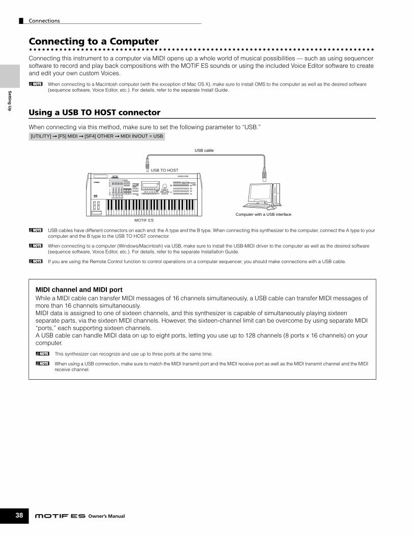
Settin
g U
p
Connections
38
Connecting to a Computer
Connecting this instrument to a computer via MIDI opens up a whole world of musical possibilities — such as using sequencer software to record and play back compositions with the MOTIF ES sounds or using the included Voice Editor software to create and edit your own custom Voices.
n When connecting to a Macintosh computer (with the exception of Mac OS X), make sure to install OMS to the computer as well as the desired software (sequence software, Voice Editor, etc.). For details, refer to the separate Install Guide.
Using a USB TO HOST connector
When connecting via this method, make sure to set the following parameter to “USB.”
n USB cables have different connectors on each end: the A type and the B type. When connecting this synthesizer to the computer, connect the A type to your computer and the B type to the USB TO HOST connector.
n When connecting to a computer (Windows/Macintosh) via USB, make sure to install the USB-MIDI driver to the computer as well as the desired software (sequence software, Voice Editor, etc.). For details, refer to the separate Installation Guide.
n If you are using the Remote Control function to control operations on a computer sequencer, you should make connections with a USB cable.
[UTILITY] ➞ [F5] MIDI ➞ [SF4] OTHER ➞ MIDI IN/OUT = USB
MIDI channel and MIDI portWhile a MIDI cable can transfer MIDI messages of 16 channels simultaneously, a USB cable can transfer MIDI messages of more than 16 channels simultaneously. MIDI data is assigned to one of sixteen channels, and this synthesizer is capable of simultaneously playing sixteen separate parts, via the sixteen MIDI channels. However, the sixteen-channel limit can be overcome by using separate MIDI “ports,” each supporting sixteen channels. A USB cable can handle MIDI data on up to eight ports, letting you use up to 128 channels (8 ports x 16 channels) on your computer.
n This synthesizer can recognize and use up to three ports at the same time.
n When using a USB connection, make sure to match the MIDI transmit port and the MIDI receive port as well as the MIDI transmit channel and the MIDI receive channel.
MUSIC PRODUCTION SYNTHESIZER
MOTIF ES
USB TO HOST
USB cable
Computer with a USB interface
Owner’s Manual

Set
tin
g U
p
Connections
Precautions when using the USB TO HOST connector
When connecting the computer to the USB TO HOST connector, make sure to observe the following points. If you do not observe these points, you risk freezing the computer, corrupting the data, and losing the data. If the computer or the instrument freezes, turn the power to the instrument off or restart the computer.
• Before connecting the computer to the USB TO HOST connector, exit from any power-saving mode (such as suspended, sleep, standby) of the computer.
• Before turning on the power to the instrument, connect the computer to the USB TO HOST connector. • Execute the following before turning the power to the instrument on/off or plugging/unplugging the USB cable to/from the USB TO HOST
connector. - Quit any open applications (such as Voice Editor, Multi Part Editor, and SQ01).- Make sure that data is not being transmitted from the instrument. (Data is transmiited only by playing notes on the keyboard or playing back a
song.)• While a USB device is connected to the instrument, you should wait for three seconds or more between these operations: When turning the power
of the instrument off then on again, or when alternately connecting/disconnecting the USB cable.
Using an IEEE1394 interface (when an optional mLAN16E has been installed)
By installing an optional mLAN16E interface, you can connect a computer (with an IEEE 1394 interface) to this instrument via a single cable.When connecting via this method, make sure to set the following parameter to “mLAN.”
The mLAN connection using an IEEE1394 cable lets you transfer both MIDI data and audio data. For example, you can record your keyboard performance and Song/Pattern playback to hard disk of the computer as audio data (page 153).
About the Thru Port SettingMIDI ports can be used to divide playback among multiple synthesizers, as well as expand the MIDI channel capacity beyond sixteen.
In the example below, a separate synthesizer connected to the MOTIF ES is played by MIDI data via port 5, as set in the ThruPort parameter with the following operation.
[UTILITY] ➞ [F5] MIDI ➞ [SF4] OTHER ➞ MIDI IN/OUT = mLAN
TIP
[UTILITY] ➞ [F5] MIDI ➞ [SF4] OTHER ➞ ThruPort = 5
MUSIC PRODUCTION SYNTHESIZER
MIDI OUT USB TO HOST
MIDI IN
Only MIDI data over port 5 will be transmitted through the MOTIF ES to this tone generator.
MIDI cable USB cable
Outputting the MIDI data via multiple ports
Only MIDI data over ports 1, 2, and 3 are recognized. For details on the relationship between the MIDI port and the tone generator block, see page 163.
CAUTION
MUSIC PRODUCTION SYNTHESIZER
MOTIF ES
mLAN16E mLAN connector
Computer with an IEEE1394 interface
IEEE1394 cable
39Owner’s Manual

Settin
g U
p
Connections
40
Using a MIDI interface
• Using the computer’s MIDI interface
• Using an external MIDI interface
n Please use the appropriate MIDI interface for your computer.
n If you are using a computer that has a USB interface, make sure to connect the computer and this synthesizer by USB. (The data transfer rate is faster than MIDI and you’ll have access to multiple MIDI ports.)
Selecting Voices from a computerYou can select Voices on this instrument from your computer software by specifying the following MIDI messages.
• Bank Select MSB• Bank Select LSB• Program Change
For details on what values are assigned to the Voice Bank/Number of this synthesizer, refer to the separate Data List.
MUSIC PRODUCTION SYNTHESIZER
MOTIF ES
MIDI OUTMIDI IN
MIDI OUTMIDI IN
MIDI cable
Computer with MIDI interface
MUSIC PRODUCTION SYNTHESIZER
MOTIF ES
MIDI OUTMIDI IN
MIDI cable MIDI interface
Serial port (modem or printer port) or USB port
Computer
Owner’s Manual

Set
tin
g U
p
Connections
Local On/Off – when Connected to a ComputerWhen connecting this synthesizer to a computer, the keyboard performance data is generally sent to the computer, and then returned from the computer to play the tone generator block. If the Local Control in the Utility mode is set to “on,” a “double” sound may result, since the tone generator is receiving performance data from both the keyboard directly and the computer. Use the setting suggestions below as a guideline; specific instructions may differ depending on your computer and the software used.
• When MIDI “Echo” (MIDI through) is set to on the software/computer:
n When transmitting or receiving System Exclusive data (such as with the Bulk Dump function), use the setting example below, making sure that MIDI “Echo” (MIDI through) on the computer software is set to “off.”
• When MIDI “Echo” (MIDI through) is set to off the software/computer:
n Although not indicated in the illustration above, the MOTIF ES actually receives and responds to MIDI data from the computer application (sequencer), regardless of the Local Control setting on the MOTIF ES.
* MIDI “Echo” is a function on sequencers that takes any data received via the MIDI IN and “echoes” it (or sends it as is) through the MIDI OUT. In some software, this function is also called “MIDI Thru.”
n For details about the MIDI Echo, refer to the owner’s manual of your particular software.
MOTIF ES IN OUT
USB TO HOST
OUT
IN
Computer (SQ01, etc.)
MIDI Echo (MIDI thru) = on
Tone generator block Keyboard
[UTILITY] ➞ [F5] MIDI ➞ [SF2] SWITCH ➞ LocalCtrl = off
OUT
IN
USB TO HOST
MOTIF ES
Computer (SQ01, etc.)
MIDI Echo (MIDI thru) = off
Tone generator block
Keyboard
[UTILITY] ➞ [F5] MIDI ➞ [SF2] SWITCH ➞ LocalCtrl = on
41Owner’s Manual

Settin
g U
p
Connections
42
Connecting Various Controllers
The MOTIF ES features several controller jacks on the rear panel — letting you independently control various aspects of the sound and a variety of functions with optional controllers.
■ Breath ControllerYou can connect an optional Breath Controller (BC3) to the BREATH jack on the rear panel. Then use it to control a large number of this synthesizer’s parameters, particularly those controlled by a wind player’s breath: dynamics, timbre, pitch and so on. The Breath Controller is ideally suited for realistic expression with wind instrument type Voices.
n Breath Controller parameters can be set for each Voice (page 192).
■ Footswitch (assignable)An optional Yamaha FC4 or FC5 Foot Switch connected to the rear panel FOOT SWITCH ASSIGNABLE jack can be assigned to a range of parameters. It is suited for switch-type (on/off) controls, such as Portamento Switch, increment/decrement of a Voice or Performance Number, start/stop of the Sequencer, and holding the Arpeggiator on or off.
n The parameter assigned to the Footswitch is set in the Utility mode (page 263).
■ Footswitch (sustain)An optional FC4 or FC5 Footswitch connected to the SUSTAIN jack on the rear panel lets you control sustain — particularly useful when playing piano and strings voices.Keep in mind that some sounds may not be suitable for use in all situations with the Sustain footswitch. For example, for organ sounds that have no natural decay, the sound continues at the same level when holding down the Sustain footswitch.
On the other hand, many sounds benefit from the use of Sustain, such as piano, which has a natural decay when a note is held. Using Sustain with these kinds of Voices provides a smooth after-sound and gives you expressive control in your performance.
n The sustain level of the Amplitude EG (page 162) is maintained while holding down the Sustain footswitch, even when releasing your fingers from the keys.
n You cannot assign a function other than Sustain to the SUSTAIN jack.
■ Foot ControllerOptional Foot Controllers (such as the FC7), connected to the FOOT CONTROLLER jacks on the rear panel, can be assigned to a number of controller parameters. By using a foot controller for parameter control, both your hands are left free to play the keyboard (or to operate other controllers) — exceptionally convenient when you’re playing live.
n Foot Controller parameters can be set for each Voice (page 192).
GREENYELLOWORANGEPlug-in SLOT
A /D INPUTLR
OUTPUTR L/MONO PHONES
ASSIGNABLE OUTPUTLR
FOOTCONTROLLER
BREATH ASSIGNABLE SUSTAINOUTTHRU
USB
TO HOSTTO DEVICEmLAN I/O EXPANSIONAC INLETON OFF
FOOTSWITCH
CARD3.3V
1INMIDI
2GAIN
FOOTCONTROLLER
BREATH ASSIGNABLE SUSTAIN
FOOTSWITCH
12
MOTIF ES rear panel
BC3FC4 or FC5
FC4 or FC5FC7
FC7
Owner’s Man
ual
Set
tin
g U
p
Turning the power on/off
Turning the power on/offPower-on Procedure
Once you’ve made all the necessary connections between your MOTIF ES and any other devices, make sure that all volume settings are turned down all the way to zero. Then turn on the every device in your setup in the order of MIDI masters (senders), MIDI slaves (receivers), then audio equipment (mixers, amplifiers, speakers, etc.). This ensures smooth signal flow from the first device to the last (first MIDI, then audio). When powering down the setup, first turn down the volume for each audio devices, then switch off each device in the reverse order (first audio devices, then MIDI).
When using the MOTIF ES as MIDI receiver:
Turning the MOTIF ES on/off
The explanations here apply when audio equipment (amplifier and speaker) is connected to the MOTIF ES.
1 Make sure that the external audio equipment is connected to the MOTIF ES properly. Also be sure to set the volume of the MOTIF ES and the external audio equipment to 0.
2 Press the POWER switch on the rear panel to turn the MOTIF ES on. The Opening display (together with the message that confirms the status of the Plug-in Board installation) appears and after a while, the Voice mode display appears.
n At the time this synthesizer is shipped from the factory, the Voice mode display will appear when turning the power on. You can change the default display when turning the power on with the following operation. [UTILITY] → [F1] GENERAL → [SF4] OTHER → PowerOnMode (Page 261)
3 Turn the power of the connected audio equipment on.
4 Raise the sound system volume of the audio equipment and the MOTIF ES gradually to a reasonable level.
5 If necessary, adjust the legibility of the LCD display by using the LCD Contrast Control.
6 After turning the power of the audio equipment off or turning down the volume of the audio equipment, turn the MOTIF ES’s power off.
MUSIC PRODUCTION SYNTHESIZER
POWERON!!
1 2 3
MUSIC SYNTHESIZERModular Synthesis Plug-in System
MIDI sender MOTIF ES
Audio equipment (first mixer, then amplifier)
AC INLETPOWER
ON OFF
Rear panel of the MOTIF ES Voice mode display
43Owner’s Manual

Settin
g U
p
Resetting the User Memory to the Initial Factory Settings
44
Resetting the User Memory to the Initial Factory SettingsThe original factory setting of this synthesizer’s User Memory (page 186) can be restored as follows.
When the factory settings are restored, all the Voice, Performance, Song, Pattern, and system setting in the Utility mode you created will be erased. Be sure to save all important data to SmartMedia or USB storage device before executing this procedure (pages 85, 91 and 131).
1 Press the [UTILITY] button to enter the Utility mode (the lamp lights).
2 Press the [JOB] button to enter the Utility Job mode.
3 Press the [ENTER] button. (The display prompts you for confirmation.)
n To cancel the Job, press the [DEC/NO] button.
4 Press the [INC/YES] button to execute the Job.After the Job has been completed, a “Completed” message appears and operation returns to the original display.
An “Executing...” or “Please keep power on” message is shown when it takes a short amount of time to execute the Job. Never attempt to turn off the power while data is being written to Flash ROM (while an “Executing...” or “Please keep power on” message is shown). Turning the power off in this state results in loss of all user data and may cause the system to freeze (due to corruption of data in the Flash ROM). This means that this synthesizer may not be able to start up properly, even when turning the power on next time.
n All settings in the Utility mode that are related to the Plug-in boards are stored only to the memory on those respective boards, and not to the User memory of this synthesizer. Because of this, the Factory Set operation cannot be used to restore settings for those boards.
CAUTION
SONG PATTERN FILE
SEQUENCER
INTEGRATEDSAMPLING MIXING UTILITY
EDIT
COMPARE SCENE STORESET LOCATE
JOB STORE
DEMO
SONG PATTERN FILE
SEQUENCER
INTEGRATEDSAMPLING MIXING UTILITY
EDIT
COMPARE SCENE STORESET LOCATE
JOB STORE
DEMO
CAUTION
Owner’s Manual

Modes
Bas
ic O
per
atio
n
In this section, we’ll take a look at the fundamental operating conventions of the MOTIF ES. Here, you’ll learn the basics – how to select modes, call up the various functions, change settings, and edit parameter values. Take time to familiarize yourself with these nuts-and-bolts operations, and you’ll be on your way to mastering the instrument. Before reading further, familiarize yourself with the basic terms used with the MOTIF ES in the chart below.
ModesMode Structure
This synthesizer is organized into various modes, each covering a different set of operations and functions.Keep in mind that there are two basic types of modes, depending on the status of the tone generator block. The first type includes the Voice and Performance modes, and the internal tone generator is used in single timbre operation — meaning that only one Voice, or one channel of MIDI data is used. The second type includes the Song and Pattern modes, and the internal tone generator is used in multi-timbral operation — meaning that several Voices, or multiple MIDI channels are used. Along with each of these types are sub modes — the Sampling mode and the Utility mode. Remember that the particular displays and parameters in these two modes differ depending on which type of mode (Voice/Performance or Song/Pattern) was active before calling up the sub-mode. In addition to the above mentioned, there are two special modes. The Master mode lets you memorize your desired settings in each mode (Voice/Performance/Song/Pattern) and recall them instantly anytime you need them with a single button. The File mode lets you manage your created data.
Basic Operation
Term Description Page
Voice Musical instrument voices 158
Performance A program in which multiple Voices are combined in a layer 158
Song Music data consisting of MIDI events 166
Pattern Rhythm pattern data which consist of MIDI events used for looped playback 167
Sampling The function that lets you record the audio data (such as your own voice and CD playback sound) and play those sounds just like any other synthesizer’s Voice. 172
Master A program which lets you register the settings in each mode – Voice, Performance, Song, and Pattern 136
File A collection of settings for storing and managing your created data 186
VOICE
SONG
PERFORM MASTER
PATTERN FILE
MODE
SEQUENCER
INTEGRATEDSAMPLING MIXING UTILITY
DEMO
VOICE
PERFORM
SONG
PATTERN
MIXING
MASTER
FILE
INTEGRATEDSAMPLING
UTILITY
Voice modeVoice Play modeVoice Edit modeVoice Job modeVoice Store mode
Performance modePerformance Play modePerformance Edit modePerformance Job modePerformance Store mode
Master modeMaster Play modeMaster Edit modeMaster Job modeMaster Store mode
File mode
Keyboard Playback mode (single timbre tone generator)
Sampling modeSampling Record modeSampling Edit modeSampling Job mode
Utility modeUtility Job mode
Song modeSong Play modeSong Record modeSong Edit modeSong Job modeSong Mixing mode
Song Mixing Edit modeSong Mixing Job modeSong Mixing Store mode
Pattern modePattern Play modePattern Record modePattern Edit modePattern Job modePattern Mixing mode
Pattern Mixing Edit modePattern Mixing Job modePattern Mixing Store mode
Keyboard Playback mode (multi-timbral tone generator)
(Mixing Voice mode)Mixing Voice Edit modeMixing Voice Job modeMixing Voice Store mode
45Owner’s Manual

Basic O
peratio
n
Modes
46
Mode table
The functions of each mode and how to enter each mode are as follows:
■ How to leave the current displayFor most operations or displays (except for the File mode, Song/Pattern Record mode, and Remote Control mode), pressing the [EXIT] button will let you leave the current display and return you to the previous one. You can return back to any of the modes — Voice Play, Performance Play, Song Play, Pattern Play, and Master Play — by pressing the [EXIT] button several times in the respective mode.
Mode Function How to enter the mode
Voice mode Voice Play mode Playing a Voice [VOICE]
Voice Edit mode Editing/Creating a Voice [VOICE] → [EDIT]
Voice Job mode Initializing a Voice, etc. [VOICE] → [JOB]
Voice Store mode Storing a Voice to internal memory [VOICE] → [STORE]
Performance mode Performance Play mode Playing a Performance [PERFORM]
Performance Edit mode Editing/Creating a Performance [PERFORM] → [EDIT]
Performance Job mode Initializing a Performance, etc. [PERFORM] → [JOB]
Performance Store mode Storing a Performance to internal memory [PERFORM] → [STORE]
Song mode Song Play mode Playing a Song [SONG]
Song Record mode Recording a Song [SONG] → [● ] (REC)
Song Edit mode Editing a Song MIDI events [SONG] → [EDIT]
Song Job mode Converting and transforming Song data [SONG] → [JOB]
Song Mixing mode Setting tone generator parameters [SONG] → [MIXING]
Song Mixing Edit mode Setting tone generator parameters in detail [SONG] → [MIXING] → [EDIT]
Song Mixing Job mode Initializing a Song Mixing, etc. [SONG] → [MIXING] → [JOB]
Song Mixing Store mode Storing a Song Mixing internal memory [SONG] → [MIXING] → [STORE]
Pattern mode Pattern Play mode Playing a Pattern [PATTERN]
Pattern Record mode Recording a Pattern [PATTERN] → [● ] (REC)
Pattern Edit mode Editing a Pattern MIDI events [PATTERN] → [EDIT]
Pattern Job mode Converting and transforming Pattern data [PATTERN] → [JOB]
Pattern Mixing mode Setting tone generator parameters [PATTERN] → [MIXING]
Pattern Mixing Edit mode Setting tone generator parameters in detail [PATTERN] → [MIXING] → [EDIT]
Pattern Mixing Job mode Initializing a Pattern Mixing, etc. [PATTERN] → [MIXING] → [JOB]
Pattern Mixing Store mode Storing a Pattern Mixing internal memory [PATTERN] → [MIXING] → [STORE]
(Mixing Voice mode) Mixing Voice Edit mode Editing/Creating a Voice dedicated for Song/Pattern [SONG] or [PATTERN] → [MIXING] → [F5] VCE ED
Mixing Voice Job mode Initializing a Mixing Voice, etc. [SONG] or [PATTERN] → [MIXING] → [F5] VCE ED → [JOB]
Mixing Voice Store mode Storing a Mixing Voice to internal memory [SONG] or [PATTERN] → [MIXING] → [F5] VCE ED → [STORE]
Sampling mode Sampling Record mode Recording a Sample [INTEGRATED SAMPLING]
Sampling Edit mode Editing a sample [INTEGRATED SAMPLING] → [EDIT]
Sampling job mode Converting and transforming Sample data [INTEGRATED SAMPLING] → [JOB]
Utility mode Utility mode Setting System related parameters [UTILITY]
Utility Job mode Resetting the User Memory to the Initial Factory Settings [UTILITY] → [JOB]
Master mode Master Play mode Playing a Master [MASTER]
Master Edit mode Editing/Creating a Master [MASTER] → [EDIT]
Master Job mode Initializing a Master, etc. [MASTER] → [JOB]
Master Store mode Storing a Master to internal memory [MASTER] → [STORE]
File mode File mode Managing Files and Folders (Directories) [FILE]
EXIT ENTER
EXECUTE
DEC/NO INC / YES
Owner’s Manual

Functions and Sub-Functions
Bas
ic O
per
atio
n
Functions and Sub-FunctionsEach mode described above contains various displays, with various functions and parameters. To navigate your way through these displays and select a desired function, use the [F1] - [F6] buttons and the [SF1] - [SF5] buttons. When you select a mode, the available displays or menus appear directly above the buttons at the bottom of the display (as shown below).
Using the Function buttons [F1] - [F6]
Depending on the currently selected mode, up to six functions are available and can be called up with the [F1] - [F6] buttons. Keep in mind that the available functions differ depending on the selected mode.
Using the Sub-Function buttons [SF1] - [SF5]
Depending on the currently selected mode, up to five functions (sub-functions) are available and can be called up with the [SF1] - [SF5] buttons. Keep in mind that the available functions differ depending on the selected mode. (Some displays may not have any sub-functions for these buttons.)
Selecting a ProgramIn order to play the MOTIF ES you’ll need to call up one of its programs, i.e., a Voice, Performance, Song, Pattern, or Master. These programs can be selected in each Play mode via the same procedure.
■ Using the [INC/YES], [DEC/NO] buttons and the data dialThe [INC/YES] and [DEC/NO] buttons let you step up or down through the program numbers in any of the Play modes (Voice, Performance, Song, Pattern, and Master).Rotating the data dial to the right (clockwise) increases the program number, while rotating it to the left (counter-clockwise) decreases it. This control works in the same way as the [INC/YES] and [DEC/NO] buttons, but lets you scroll through the programs more quickly.
SCENESF1 SF2 SF3 SF4 SF5
F1 F2 F3 F4 F5 F6
INFORMATION
These functions can be selected via the corresponding button ([F1] - [F6]).
In this example, press the [F5] button to go to the LFO display.
SCENESF1 SF2 SF3 SF4 SF5
F1 F2 F3 F4 F5 F6
INFORMATION
These functions can be selected via the corresponding button ([SF1] - [SF5]).
In this example, press the [SF5] button to go to the OTHER display.
DEC/NO INC / YES
Decreases number Increases number
Increases numberDecreases number
47Owner’s Manual

Basic O
peratio
n
Selecting a Program
48
■ Using the [GROUP], [NUMBER] buttonsAs shown below, you can select a program number by pressing any of the GROUP [A] - [H] buttons and pressing any of the NUMBER [1] - [16] buttons.
n The convenient Category Search function (page 62) lets you easily locate and select the Voices you want by type.
The Voice program numbers and the corresponding Group/Numbers are listed below.
n When selecting a Voice, it is necessary to press one of the [BANK] buttons before pressing the [GROUP] and [NUMBER] buttons.
n The amount of numbers differ depending on the program. For example, while the selected number range of the Normal Voice, Performance, and Master is 001 - 128, the selected number range of the Song and Pattern is 001- 064.
Program Number Group Number Program
Number Group Number Program Number Group Number Program
Number Group Number
001 A 1 033 C 1 065 E 1 097 G 1
002 A 2 034 C 2 066 E 2 098 G 2
003 A 3 035 C 3 067 E 3 099 G 3
004 A 4 036 C 4 068 E 4 100 G 4
005 A 5 037 C 5 069 E 5 101 G 5
006 A 6 038 C 6 070 E 6 102 G 6
007 A 7 039 C 7 071 E 7 103 G 7
008 A 8 040 C 8 072 E 8 104 G 8
009 A 9 041 C 9 073 E 9 105 G 9
010 A 10 042 C 10 074 E 10 106 G 10
011 A 11 043 C 11 075 E 11 107 G 11
012 A 12 044 C 12 076 E 12 108 G 12
013 A 13 045 C 13 077 E 13 109 G 13
014 A 14 046 C 14 078 E 14 110 G 14
015 A 15 047 C 15 079 E 15 111 G 15
016 A 16 048 C 16 080 E 16 112 G 16
017 B 1 049 D 1 081 F 1 113 H 1
018 B 2 050 D 2 082 F 2 114 H 2
019 B 3 051 D 3 083 F 3 115 H 3
020 B 4 052 D 4 084 F 4 116 H 4
021 B 5 053 D 5 085 F 5 117 H 5
022 B 6 054 D 6 086 F 6 118 H 6
023 B 7 055 D 7 087 F 7 119 H 7
024 B 8 056 D 8 088 F 8 120 H 8
025 B 9 057 D 9 089 F 9 121 H 9
026 B 10 058 D 10 090 F 10 122 H 10
027 B 11 059 D 11 091 F 11 123 H 11
028 B 12 060 D 12 092 F 12 124 H 12
029 B 13 061 D 13 093 F 13 125 H 13
030 B 14 062 D 14 094 F 14 126 H 14
031 B 15 063 D 15 095 F 15 127 H 15
032 B 16 064 D 16 096 F 16 128 H 16
ELEMENT/PERF. PART/ZONE
A. PIANO KEYBOARD ORGAN
PRE 5 PRE 6 USER 1
GUITAR/PLUCKED
SYN LEAD
A B C D E F G H
87654321
16 MUTE
TRACKSELECT
SECTION GROUP
NUMBER
CATEGORYSEARCH BANK
SOLO
151412 1311109
SYN PAD/CHOIR
SYN COMP CHROMATICPERCUSSION
DRUM/PERCUSSION
SE MUSICAL FX COMBI
USER 2
STRINGS
PLG 1
SLOT 1 SLOT 2 SLOT 3
BRASS
PLG 2
REED/PIPE
PLG 3
BASS
GM
The explanations here apply when these four button indicators are off.
Owner’s Manual

Moving the Cursor and Setting Parameters
Bas
ic O
per
atio
n
Moving the Cursor and Setting Parameters
■ Inputting a number directlyFor parameters having large value ranges (such as the start and end points of a sample), you can also enter the value directly, using the buttons below the LCD display as a numeric keypad. When the cursor is located on such a parameter, the [NUM] icon appears at the lower right corner of the LCD display indicating that you can call up the number input window by pressing the [INFORMATION] button. From this window, you can input a number directly by pressing the [F1] - [F6] buttons and the [SF1] - [SF5] buttons. First, press the [F6] button so that the cursor appears at the Input Number within the bracket. Move the cursor to the desired digit by using the Cursor buttons [>] and [<], then input the number of the selected digit. After completing the number input, press the [ENTER] button to actually enter the number. Press the [EXIT] button to go back to the original display.
■ Selecting a note typeWhen the cursor is located on the parameter to which the note type is set, the note icon appears at the lower right corner indicating that you can call up the Note Type selection window by pressing the [INFORMATION] button. You can specify the note type by pressing the [F1] - [F6] buttons and the [SF1] - [SF5] buttons. After selecting one of the note types, press the [ENTER] button to actually enter the selection. Press the [EXIT] button to go back to the original display.
EXIT ENTER
EXECUTE
DEC/NO INC / YESMoving the cursorUse these four buttons to navigate the display, moving the cursor around the various selectable items and parameters in the screen. When selected, the relevant item is highlighted (the cursor appears as a dark block with inverse characters). You can change the value of the item (parameter) at which the cursor is located by using the data dial, [INC/YES] and [DEC/NO] buttons.
Changing (editing) parameter valuesRotating the data dial to the right (clockwise) increases the value, while rotating it to the left (counter-clockwise) decreases it.
For parameters with large value ranges, you can increase the value by 10 by simultaneously holding down the [INC/YES] button and pressing the [DEC/NO] button. To decrease by 10, do the opposite; simultaneously hold down the [DEC/NO] button and press the [INC/YES] button.
SCENESF1 SF2 SF3 SF4 SF5
F1 F2 F3 F4 F5 F6
INFORMATIONSCENE
SF1 SF2 SF3 SF4 SF5
F1 F2 F3 F4 F5 F6
INFORMATION
Number Input window Input Number
SCENESF1 SF2 SF3 SF4 SF5
F1 F2 F3 F4 F5 F6
INFORMATIONSCENE
SF1 SF2 SF3 SF4 SF5
F1 F2 F3 F4 F5 F6
INFORMATION
Note Type selection window
49Owner’s Manual

Basic O
peratio
n
Knob (KN) and Control Slider (CS)
50
Knob (KN) and Control Slider (CS)
Knob (KN)
You can change the brightness and tone characteristics of the current Voice or Performance in realtime by turning the knobs while you play. Rotating it to the right (clockwise) increases the program number, while rotating it to the left (counter-clockwise) decreases it. You can select the function set assigned to the knobs among the following seven sets by pressing the appropriate [KNOB CONTROL FUNCTION] button.
Function sets assigned to the Knobs (KN)
* For Drum Voices, this affects the release time for all played notes, whether held or released.** Available only when setting the Zone Switch to on in the Master Mode (page 137)
When pressing any of the [KNOB CONTROL FUNCTION] buttons, the lamp(s) of the buttons will light according to the above table and the status of the Knobs and Control Sliders (currently assigned functions and set values) is shown on the LCD display. The appearance of the knob in the display indicates the actual control status of the knob. When a knob indication is black, the control knob on the panel affects the sound. When an indication is white, moving the panel knob does not affect the sound, until the current value is reached (after which the indication turns black, indicating normal control).
Operation Button of which the lamp is turned on
Functions controlled by each Knob
KN1 (Knob 1) KN2 (Knob 2) KN3 (Knob 3) KN4 (Knob 4)
When pressing the [PAN/SEND] button
[PAN/SEND] button Pan (stereo position) of the Voice/Performance
Reverb Send Level Chorus Send Level Tempo of the Song/Pattern/Arpeggio playback
When pressing the [TONE] button
[TONE] button Filter Cutoff Frequency (degree of brightness)
Resonance (the level of the signal in the area of the cutoff frequency)
Attack Time of the sound
Release Time of the sound (decay time after the key is released)*
When pressing the [ARP FX] button
[ARP FX] button Swing degree of the Arpeggio playback
Gate time (length) of the Arpeggio playback
Velocity of the Arpeggio playback
Arpeggio playback time
When pressing the [EQ] button
[EQ] button Low band of the Master EQ in the Voice/Performance mode, part EQ in the Song/Pattern mode
Low-mid band of the Master EQ in the Voice/Performance mode, Mid band of the Part EQ in the Song/Pattern mode
High-mid band of the Master EQ in the Voice/Performance mode. (Not available in the Song/Pattern mode.)
High band of the Master EQ in the Voice/Performance mode, part EQ in the Song/Pattern mode
When pressing the [PAN/SEND] button and the [TONE] button simultaneously
[PAN/SEND] button[TONE] button
Function assigned from the [UTILITY] → [F2] CTLASN → [SF2] ASSIGN display (page 263) in the Utility mode
Function assigned for each Voice from the [VOICE] → [EDIT] → [COMMON] → [F4] CTLSET display (page 155)
When pressing the [TONE] button and the [ARP FX] button simultaneously**
All the buttons are off Function assigned for each Master from the [MASTER] → [EDIT] → Zone selection → [F5] KN/CS display (page 140)
When pressing the [ARP FX] button and the [EQ] button simultaneously
[ARP FX] button[EQ] button
Function assigned to the Master Effect parameters from the [UTILITY] → [F4] CTLASN → [SF5] MEF display.
KNOBCONTROLFUNCTION
SWING
CUTOFF
PAN
ASSIGN A
GATE TIME
RESONANCE
REVERB
ASSIGN B
VELOCITY
ATTACK
CHORUS
ASSIGN 1
UNITMULTIPLY
RELEASE
TEMPO
ASSIGN 2
LOW
KN 1LOW MID
KN 2HIGH MID
KN 3HIGH
KN 4
ARP FX
EQ
TONE
ASSIGN
PAN/SEND
Turning these Knobs will affect the sound.
Turning these Knobs will not affect the sound.
Owner’s Manual

About the editing functions
Bas
ic O
per
atio
n
Control Slider (CS)
You can adjust the volume of the Voice/Performance you play on the keyboard, or the volume of the specified part (track) of the Song/Pattern by using the Control Sliders (CS). In the Master mode, various functions as well as the volume can be assigned to the Control Sliders (CS) when the Zone Switch is set to on (page 135).
Function sets assigned to the Control Slider (CS)
n The [MASTER VOLUME] slider adjusts the overall output level of the instrument, while the Control Sliders adjust the MIDI Volume setting of the corresponding Element or Part.
About the editing functionsThere are three types of method for creating data – Editing parameters (Voice, Performance, etc.), Recording MIDI data (Song, Pattern, etc.), and Recording audio data (Sampling). In this section, we’ll explain the basic operations for editing the Voice, Performance, Song Mixing, Pattern Mixing, Mixing Voice settings.
n For details on recording MIDI data, see pages 118 (Song) and 110 (Pattern). For details on recording audio data (for Sampling), see pages 94 and 107.
n The Song Edit function (for editing the Song MIDI sequence data) and the Pattern Edit function (for editing the Pattern MIDI sequence data) are not explained here. See page 124.
Edit Indicator
You can adjust or set various parameters by using the data dial, [INC/YES] button, [DEC/NO] button, Knobs, and Control Sliders in the Voice mode (Play/Edit mode), Performance mode (Play/Edit mode), Song Mixing mode, Pattern Mixing mode, and Mixing Voice mode. When changing the value of the parameter in these modes, the [E] (Edit Indicator) will appear on the top left corner of the LCD display. This indicates that the current program has been modified but not yet stored. If you wish to store your sound obtained by edit operation, be sure to store the current program to internal User memory in the Store mode before selecting another program.
ModeFunctions controlled by each Slider
CS1 CS2 CS3 CS4
Voice mode When a Normal Voice is selected (page 60) Element1 Volume Element2 Volume Element3 Volume Element4 Volume
When a Drum Voice is selected (page 61) Volume of the entire Voice sound (moving any Slider produces same volume)
Performance mode Part1 Volume Part2 Volume Part3 Volume Part4 Volume
Song mode/Pattern mode When tracks (Parts) 1 - 4 are selected Track1 (Part1) Volume Track2 (Part2) Volume Track3 (Part3) Volume Track4 (Part4) Volume
When tracks (Parts) 5 - 8 are selected Track5 (Part5) Volume Track6 (Part6) Volume Track7 (Part7) Volume Track8 (Part8) Volume
When tracks (Parts) 9 - 12 are selected Track9 (Part9) Volume Track10 (Part10)
VolumeTrack11 (Part11) Volume
Track12 (Part12) Volume
When tracks (Parts) 13 - 16 are selected
Track13 (Part13) Volume
Track14 (Part14) Volume
Track15 (Part15) Volume
Track16 (Part16) Volume
Master mode When the Zone Switch is set to on (page 137)
Function assigned for each Master from the [MASTER] → [EDIT] → Zone selection → [F4] KN/CS display (page 140)
EDIT
COMPARE SCENE STORESET LOCATE
JOB STORE
Edit Indicator
Voice EditPerformance EditSong Mixing Edit
Pattern Mixing EditMixing Voice Edit
If the Edit Indicator appears...
Voice StorePerformance StoreSong Mixing Store
Pattern Mixing StoreMixing Voice Store
51Owner’s Manual

Basic O
peratio
n
Confirmation Message
52
Compare Function
This convenient function lets you switch between the edited sound and its original, unedited condition – allowing you to listen to the difference between the two and better hear how your edits affect the sound.For example, when editing a Voice in the Voice Edit mode, the “E” Edit indicator is shown. Pressing the [COMPARE] button in this condition reverts to the original unedited sound (the button lamp flashes and the “C” Compare indicator is shown). Press the [COMPARE] button again to return to the edited sound.
Edit Recall Function
If you are editing a program and select a different program without storing your edited one, all the edits you’ve made will be erased. However, the edited program is maintained in a backup memory location called the Recall buffer (page 187). To restore the lost data with your latest edits intact, use the Edit Recall function in the Job mode.
Confirmation MessageWhen you execute certain operations, such as those in the Job, Store, and File modes, this synthesizer shows a confirmation message. This lets you actually execute the operation or cancel it if desired.
If a confirmation message (like the one illustrated above) appears, press the [INC/YES] button to execute the operation or press the [DEC/NO] button to cancel it.
Job mode How to call up the Edit Recall display
Voice [VOICE] → [JOB] → [F2] RECALL
Performance [PERFORM] → [JOB] → [F2] RECALL
Song Mixing [SONG] → [MIXING] → [JOB] → [F2] RECALL
Pattern Mixing [PATTERN] → [MIXING] → [JOB] → [F2] RECALL
Mixing Voice [SONG] or [PATTERN] → [MIXING] → [F5] VCE ED → [JOB] → [F2] RECALL
EDIT
COMPARE SCENE STORESET LOCATE
JOB STOREEDIT
COMPARE SCENE STORESET LOCATE
JOB STORE
Edit Indicator (newly edited sound) Changes to the Compare Indicator (original sound)
Lamp flashes
Owner’s Manual

Information Display
Bas
ic O
per
atio
n
Information DisplayThis convenient function lets you call up relevant details about the selected mode – simply by pressing the [INFORMATION] button. For example, when the Voice mode is active, you can quickly check information about which voice bank is selected, what Play mode (poly or mono) is being used, which effects are applied, and so on.
For details, see page 275.
Note (Key) settingsSeveral parameters let you set a key range for a function – for example, in setting up a keyboard split – by specifying certain note values. You can use the [INC/YES] and [DEC/NO] buttons or data dial to set these parameters, or you can directly enter the values from the keyboard by pressing the appropriate keys (as shown below).
n About the note name assigned to each key, see page 16.
NamingYou can freely name the created data like Voice and the file saved to the SmartMedia/USB storage device. The chart below lists the types of data that can be named along with the operations for calling up the respective naming displays.
First, call up the name input display according to the above table, then, move the cursor by using the Cursor button to the desired location and input a character. See below for details.
n Since the name of the program is part of the data, make sure that you properly save the program after naming it.
Data types that can be named How to call up the naming display Page
Voice [VOICE] → [EDIT] → [F1] GENERAL → [SF1] NAME 80
Performance [PERFORM] → [EDIT] → [F1] GENERAL → [SF1] NAME 89
Song [SONG] → [JOB] → [F6] SONG → 04: Song Name 233
Pattern [PATTERN] → [JOB] → [F6] PATTERN → 05: Pattern Name 248
Mixing Template [SONG] or [PATTERN] → [MIXING] → [JOB] → [F6] TEMPLATE 237
Mixing Voice [SONG] or [PATTERN] → [MIXING] → [F5] VCEED → [F1] GENERAL →[SF1] NAME 106
Phrase [PATTERN] → [JOB] → [F4] PHRASE → 09: Phrase Name 246
Master [MASTER] → [EDIT] → [F1] NAME 138
Waveform [INTEGRATED SAMPLING] → [JOB] → [F2] WAVE → 04: NAME 259
Arpeggio [SONG] → [JOB] → [F5] TRACK → 07: Put Track To Arp 130
[PATTERN] → [JOB] → [F5] TRACK → 06: Put Track To Arp 130
Volume Label of the SmartMedia/USB storage device [FILE] → [F1] CONFIG → [SF3] FORMAT 266
File/Folder saved to the SmartMedia/USB storage device [FILE] → [F2] SAVE or [F4] RENAME 132
INFORMATION
INFORMATION
When Note Limit is selected, the [KBD] mark appears, indicating that you can use the keyboard to set the value. Simultaneously hold down the [INFORMATION] button and press the appropriate key.
53Owner’s Manual

Basic O
peratio
n
Naming
54
■ Basic naming operationAs shown below, you can set the name by repeating the two operations – moving the cursor to the desired location by using the Cursor button and selecting a character by using the data dial, [INC/YES] button, and [DEC/NO] button.
■ Using the character listIf you find it difficult to select the desired characters with the above method, you may want to use the following method — selecting the characters from a list.
EXIT ENTER
EXECUTE
DEC/NO INC / YES
DEC/NO INC / YES
Moving the cursor to the desired location on the name Selecting a character at the cursor location
EXIT ENTER
EXECUTE
DEC/NO INC / YES
DEC/NO INC / YES
INFORMATION
INFORMATION INFORMATION
When the cursor is located at the Name, this [LIST] icon appears and you can call up the Character List display by holding the [INFORMATION] button. Release the [INFORMATION] button to return back to the original display.
Select a character for the cursor location on the name.Move the cursor to the desired location.
Perform the operations below while holding the [INFORMATION] button.
Owner’s Manual

Playing the Demo Songs/Patterns
Qu
ick
Gu
ide
— P
layi
ng
th
e M
OT
IF E
S
Playing the Demo Songs/PatternsHere’s the best place to start your explorations of the MOTIF ES. The Song and Pattern Demos have been specially programmed so you can hear just how amazing the sounds are, and find out just how powerful the instrument really is — for music creation, performance and production. Before you can play the Demos, you’ll need to load the Demo data (contained in ROM) to the DRAM memory location as shown below.
n For details about ROM and DRAM, see page 187.
When the Demo Song/Pattern data is loaded, the memory area for playback will be overwritten and the following Utility settings will be changed in order to play back the Demo Song/Pattern properly. [UTILITY] →→→→ [F1] GENERAL →→→→ [SF1] TG →→→→ Volume, NoteShift, Tune[UTILITY] →→→→ [F1] GENERAL →→→→ [SF4] OTHER →→→→ CtrlRest[UTILITY] →→→→ [F1] GENERAL →→→→ [SF3] EF BYPASImportant data should always be backed up to a SmartMedia/USB storage device.
Quick Guide — Playing the MOTIF ES
(ROM)
Load
Load
Song 01
Sections A - P Sections A - P
Song 02
(DRAM)
(ROM) (DRAM)
A P A P
Song 01
Song 02
Song 64
Pattern 01
Pattern 02
Pattern 01
Pattern 02
Pattern 64
Demo Song data Memory area for Song playback
Memory area for Pattern playbackDemo Pattern data
CAUTION
1 Press the [FILE] button and [UTILITY] button simultaneously.
VOICE
SONG
PERFORM MASTER
PATTERN FILE
MODE
SEQUENCER
INTEGRATEDSAMPLING MIXING UTILITY
DEMO
You can select from the three Load Types listed below. Here, we’ll select “All.”
2 Set the LoadType to “All.”
All Loads both the Demo Song and Pattern data.
Song Loads only the Demo Song data.
Pattern Loads only the Demo Pattern data.
55Owner’s Manual

Qu
ick Gu
ide —
Playin
g th
e MO
TIF
ES
Playing the Demo Songs/Patterns
56
After the data is loaded, the Song Play display is automatically called up.
If “Pattern” is selected in step #2 above, the Pattern Play display is automatically called up once the data is loaded.
n Keep in mind that the example displays shown in this manual are for instruction purposes only, and the contents (for example, the Demo Song/Pattern names) may differ slightly from those on your instrument.
When playback of the selected Song is finished, the Song automatically stops. You can stop the Song anytime during playback by pressing the [■ ] (Stop) button. This pauses the song at the current position. To resume playback of the Song from that point, press the [F] (Play) again. To instantly return to the beginning of the Song, press the [ ] (Top) button.
Move the cursor to “Song Number: Name” (with the cursor buttons) then select another song by using the Data Dial, or the [INC/YES] and [DEC/NO] buttons.
3 Press the [ENTER] button to load the Demo data.
4 Press the [F] (Play) button to start Song playback.
5 Select and play another Demo Song.
SEQ TRANSPORT
LOCATE 1 2
SEQ TRANSPORT
LOCATE 1 2
Start Stop
Top button
SEQ TRANSPORT
LOCATE 1 2
DEC/NO INC / YES
Decreases number Increases number
Increases numberDecreases number
Song Number: Name
Start
Owner’s Manual
Next, let’s play a Demo Pattern.
There is another way to start Pattern playback – by pressing the note son the keyboard. Move the cursor to the keyboard icon and press the [INC/YES] button so that the F mark appears. In this status, press any key to start the pattern playback.
Press the [DEC/NO] button with the cursor located at the keyboard icon to turn the F mark off.
Make sure that the [SECTION] lamp is on (press the button if necessary), then press any of the buttons shown below to select and play the various Sections contained in a Pattern. Pressing the [A] - [H] buttons calls up Sections A - H and pressing the [PRE5] - [PLG3] buttons calls up the Sections I - P. Try out various rhythm variations by changing the Section.
n Some Sections of the Demo Pattern may have no data. Because of this, selecting some Sections may result in no sound.
6 Press the [PATTERN] button to enter the Pattern mode.
7 Press the [F] (Play) button to start Pattern playback.
8 Select different Sections of the Pattern.
VOICE
SONG
PERFORM MASTER
PATTERN FILE
MODE
SEQUENCER
INTEGRATEDSAMPLING MIXING UTILITY
DEMO
A. PIANO KEYBOARD ORGAN
PRE 5 PRE 6 USER 1
GUITAR/PLUCKED
SYN LEAD
A B C D E F G H SECTION GROUP
CATEGORYSEARCH BANK
SYN PAD/CHOIR
SYN COMP CHROMATICPERCUSSION
DRUM/PERCUSSION
SE MUSICAL FX COMBI
USER 2
STRINGS
PLG 1
BRASS
PLG 2
REED/PIPE
PLG 3
BASS
GM

Qu
ick
Gu
ide
— P
layi
ng
th
e M
OT
IF E
S
Playing the Demo Songs/Patterns
Unlike Song playback, Pattern playback continues in a loop until the [■ ] (Stop) button is pressed. You can stop the Pattern anytime during playback by pressing the [■ ] (Stop) button. This pauses the Pattern at the current position. To resume playback of the Pattern from that point, press the [F] (Play) again. To instantly return to the beginning of the Pattern, press the [ ] (Top) button.
Selecting a Pattern is done in the same way as selecting a Song. Refer to step #5 above.
Parameters in the Song Play mode
9 Press the [■ ] (Stop) button to stop Pattern playback.
10 Select and play another Demo Song.
SEQ TRANSPORT
LOCATE 1 2
SEQ TRANSPORT
LOCATE 1 2
Start Stop
Top button
03 : New Song 1
Song track number and track mute/solo status
Track data status
Indicates muted track.
Indicates soloed track (page 58).
Indicates that the track has no recorded data.
Indicates a sample track (page 168) containing a Sample Voice (page 173).
Indicates a MIDI track (page 168) containing MIDI sequence data.
Location settings for the selected Song
Measure : Beat(for current playback location)
ARP1-ARP5Use the [SF1] - [SF5] buttons to call up the Arpeggio type and Song Scene assigned to each button (page 123). Tempo for the selected Song
Time signature for the selected Song (You can change the value by moving the cursor here and using the [INC/YES]/[DEC/NO] buttons and data dial.)
Transpose setting (for entire Song)
Currently selected Song
Song number Song name
57Owner’s Manual

Qu
ick Gu
ide —
Playin
g th
e MO
TIF
ES
Playing the Demo Songs/Patterns
58
Using Mute/Solo with the Song and Pattern tracks
Try this with the Demo Songs to hear how the tracks sound both in isolation and in various combinations.
■ To mute a track
The corresponding track is set to mute (its lamp goes off) and produces no sound. When pressing the same number button again, the track mute is canceled (its lamp lights).
To turn Mute off, press the [MUTE] button again (the lamp goes off).
■ To solo a trackSimultaneously hold down the [MUTE] button and press one of the NUMBER buttons [1] to [16] to solo the corresponding track. Once you’ve selected a track for soloing, the [MUTE] button’s lamp flashes, indicating the Solo function is active. While Solo is active, you can change the soloed track simply by pressing the corresponding NUMBER button [1] to [16].To cancel the Solo function, press the [MUTE] button again.
Selecting a Song/Pattern track and playing the keyboard
You can play along with the Song or Pattern using the sound of a track — for example, playing additional drum/percussion sounds on a drum track while the Song plays. Press the [TRACK SELECT] button so that its lamp lights, and select a track by pressing the one of the NUMBER buttons [1] to [16].
1 Press the [MUTE] button (the lamp lights).
2 Press any of the NUMBER [1] - [16] buttons to select the track number to be muted.
ELEMENT/PERF. PART/ZONE
87654321
16 MUTE
TRACKSELECT
NUMBER
SOLO
151412 1311109
ELEMENT/PERF. PART/ZONE
87654321
16 MUTE
TRACKSELECT
NUMBER
SOLO
151412 1311109
Owner’s Manual
If you want you can also mute a track and play the part of the track yourself. To do this, select the desired track as described, then mute the track (as explained in “To mute a track” above).
Song Location
The Song Play mode has a convenient Location function that lets you jump to user-specified parts of a song. This lets you assign a specific measure number in the selected song, and instantly jump to the assigned measure – either during playback or when the song is stopped. Two Locations can be assigned.
■ Assigning LocationsSelect the desired measure in the recorded song for the Location. (Highlight “MEAS” and use the [INC/YES] and [DEC/NO] buttons or data dial.) Then, to assign the measure to Location 1, simultaneously hold down the [SET LOCATE] button and press the [G] (Reverse) button.To assign Location 2, use the [H] (Forward) button.
■ Jumping to an assigned LocationTo instantly jump to the assigned Location 1 or 2, simultaneously hold down the [LOCATE] button and pressing the [G] (Reverse) button (for Location 1) or the [H] (Forward) button (for Location 2).
ELEMENT/PERF. PART/ZONE
87654321
16 MUTE
TRACKSELECT
NUMBER
SOLO
151412 1311109
EDIT
COMPARE SCENE STORESET LOCATE
JOB STORE SEQ TRANSPORT
LOCATE 1 2
Specify a measure number to be registered.
In this example, the selected measure is assigned to Location 1. The current settings for Locations 1 and 2 are shown at the top right of the display.
SEQ TRANSPORT
LOCATE 1 2

Playing the Demo Songs/Patterns
Qu
ick
Gu
ide
— P
layi
ng
th
e M
OT
IF E
S
Song Chain
This function allows Songs to be “chained” together for automatic sequential playback. In this section, try using the Song Chain features with the Demo Songs.
From this display you can program and play your own custom Song sequences.
Move the cursor to “001” by using the cursor buttons and select the desired Song by using the Data Dial, or the [INC/YES] and [DEC/NO] buttons. Likewise, assign the other Songs to locations 002, 003, 004, and so on.
1 Press the [F6] CHAIN button to call up the Song Chain display.
2 Program the desired order of the Songs.
In addition, the following parameters can be set in the Song Chain.
Move the cursor to the top of the Song Chain display, and press the [F] (Play) button to start Song playback.
When the Song Chain programmed in step #2 reaches to the end, playback stops automatically. Press the [■ ] (Stop) button during playback to stop Song Chain playback.
n The Song Chain can only be played back in the Song Chain display, and not from any other display.
skip Skips past (ignores) the selected chain number and continues playback from the next chain number.
stop Stops Song Chain playback at that chain number. You can restart Song Chain playback from the next chain number by pressing the [F] (Play) button.
end Indicates the end mark of the Song Chain data.
3 Play the Song Chain.
SEQ TRANSPORT
LOCATE 1 2
Parameters in the Pattern Play mode
Pattern Chain
Pattern Chain allows you to string several different Sections together to make a single Song. About the Pattern Chain structure, see page 168. For information on how to create Pattern Chain data, see page 115.
01 : New Pattern A
Pattern track number and track mute/solo status
When theFmark appears, pressing any note on the keyboard starts Pattern playback (page 56).
Track data status
Indicates a MIDI track (page 168) containing MIDI sequence data.
Indicates a sample track (page 168) containing a Sample Voice (page 173).
Indicates that the track has no recorded data. (No Phrase is assigned.)
Indicates soloed track (page 58).
Indicates muted track.
Measure : Beat(for current playback location)
ARP1-ARP5Use the [SF1] - [SF5] buttons to call up the Arpeggio type assigned to each button (page 123).
Tempo for the selected PatternTime signature for the selected pattern
(You can change the value by moving the cursor here and using the [INC/YES]/[DEC/NO] buttons and data dial.)
Transpose setting (for entire Pattern)
Pattern number
Currently selected Pattern and Section
Pattern number Section
59Owner’s Manual

Playing the Keyboard (in the Voice Play mode)
60
Qu
ick Gu
ide —
Playin
g th
e MO
TIF
ES
Playing the Keyboard (in the Voice Play mode)The Voice Play mode is where you select and play the instrument sounds (voices) of this synthesizer.
Selecting a Voice
Selecting a Normal Voice
Internally, there are two Voice Types: Normal Voices and Drum Voices. Normal Voices are mainly pitched musical instrument-type sounds that can be played over the range of the keyboard. Drum Voices are mainly percussion/drum sounds that are assigned to individual notes on the keyboard. In this section, we’ll show you how to select a Normal Voice.You can select the desired Voice from various Voice Banks (Preset 1~6, User 1~2, GM preset, Plug-in 1~3) as shown below.
In this condition, playing the keyboard sounds the Voice indicated in the display. The parameters shown in the Voice Play mode are briefly explained below.
n Keep in mind that the example displays shown in this manual are for instruction purposes only, and the contents (for example, the Voice name here) may differ slightly from those on your instrument.
1 Press the [VOICE] button to enter the Voice Play mode.
A. PIANO KEYBOARD ORGAN
PRE 5 PRE 6
PRE 1 PRE 2 PRE 3 PRE 4
USER 1
GUITAR/PLUCKED
USER 2
STRINGS
PLG 1
SLOT 1 SLOT 2 SLOT 3
BRASS
PLG 2
REED/PIPE
PLG 3
BASS
GM
Preset BankContains the Voices built into this instrument.
User BankContains the voices you create in the Voice Edit mode.
Plug-in BankAvailable when Plug-in Boards have been installed. See page 74.
GM BankContains the voices allocated according to the GM standard. For details, see page 160.
Voice Bank
USR1 : 001 (A01) Gt : MegaAcGtr
VOICE PERFORM MASTER
MODE
ARP1-ARP5Use the [SF1] - [SF5] buttons to call up the Arpeggio type assigned to each button (page 66).
Indicates the Keyboard MIDI transmit channel. See page 64 for details.
Indicates the Keyboard Octave setting set via the [OCTAVE] buttons. See page 63 for details.
Indicates the functions assigned to the respective Control knobs. See page 81.
Bank (selected via the BANK buttons)
Number(selected via the NUMBER [1]-[16] buttons)
Group(selected via the GROUP [A]-[H] buttons)
Voice Program number (corresponding to Groups A to H and Numbers 01 to 16)
Bank and Voice Program number
Indicates the currently selected voice.
Category and Voice name
Category Voice name
Owner’s Manual

Playing the Keyboard (in the Voice Play mode)
Qu
ick
Gu
ide
— P
layi
ng
th
e M
OT
IF E
S
Select one of the Banks from Preset 1~6, User 1~2, and GM.
Voices in each Bank are divided into Groups [A] ~ [H]. Select a Group to display the Voices that belong to the selected Group.
Press one of the NUMBER [1] - [16] buttons.
2 Select a Normal Voice Bank.
3 Select a Normal Voice Group.
4 Select a Normal Voice Number.
5 Play the keyboard.
A. PIANO KEYBOARD ORGAN
PRE 5 PRE 6
PRE 1 PRE 2 PRE 3 PRE 4
USER 1
GUITAR/PLUCKED
USER 2
STRINGS
PLG 1
SLOT 1 SLOT 2 SLOT 3
BRASS
PLG 2
REED/PIPE
PLG 3
BASS
GM
VoiceGroup
SYN LEAD
A B C D E F G H SECTION GROUP
SYN PAD/CHOIR
SYN COMP CHROMATICPERCUSSION
DRUM/PERCUSSION
SE MUSICAL FX COMBI
ELEMENT/PERF. PART/ZONE
87654321
16 MUTE
TRACKSELECT
NUMBER
SOLO
151412 1311109
Selecting a Drum Voice
Internally, there are two Voice Types: Normal Voices and Drum Voices. Normal Voices are mainly pitched musical instrument-type sounds that can be played over the range of the keyboard. Drum Voices are mainly percussion/drum sounds that are assigned to individual notes on the keyboard. In this section, we’ll show you how to select a Drum Voice.
While holding the [DRUM KITS] button, press one of the arrow-indicated buttons: [PRE5] (Preset Drum), [USER1] (User Drum), or [GM] (GM Drum).
This operation is basically the same as in selecting a Normal Voice. You can select a Group from A to D when selecting the Preset Drum Bank in step #2. You can select a Group from A or B when selecting the User Drum Bank in step #2. You can select only A when selecting the GM Drum Bank in step #2.
This is the same as in selecting a Normal Voice.
n For details about the instrument assignments for each key, refer to the separate Data List.
Using the [INC/YES], [DEC/NO] buttons and data dialYou can select a Voice Number by using the [INC/YES], [DEC/NO] buttons and data dial in steps #3 and #4.
n The procedure for selecting Voices in other modes differs from above. For details on selecting Voices in the Performance mode, see page 71. For details on selecting Voices in the Song/Pattern mode, see page 102.
1 Press the [VOICE] button to enter the Voice Play mode.
2 Select a Drum Voice Bank.
3 Select a Drum Voice Group.
4 Select a Drum Voice Number.
5 Play the keyboard and check what instrument is assigned to each key.
FAVORITES
DRUM KITS
A. PIANO KEYBOARD ORGAN
PRE 5 PRE 6 USER 1
GUITAR/PLUCKED
USER 2
BASS
GM
DEC/NO INC / YES
Decreases number Increases number
Decreases number Increases number
61Owner’s Manual

Qu
ick Gu
ide —
Playin
g th
e MO
TIF
ES
Playing the Keyboard (in the Voice Play mode)
62
Using the Category Search function
This synthesizer features a powerful Category Search function that gives you quick access to the sounds you want, irrespective of their bank locations. Simply select a Voice category, such as A. PIANO or SYN LEAD, and you can browse through all related Voices one by one – and audition each of them, too. If you’ve installed a Plug-in Board to the instrument, those Voices are automatically included in the search as well. Plus, you can use the special Favorites category to store the Voices you use most.
In this condition with the button lit, you can use the BANK and GROUP buttons to specify the Category. Press the [CATEGORY SEARCH] button again to turn this function off.
Press one of the BANK and GROUP buttons to call up the selected Category name and the Voice list. The first Voice in the Category is selected.
1 Turn the Category Search function on by pressing the [CATEGORY SEARCH] button.
2 Select a Category.
A. PIANO KEYBOARD ORGAN
PRE 5 PRE 6 USER 1
GUITAR/PLUCKED
SYN LEAD
A B C D E F G H SECTION GROUP
CATEGORYSEARCH BANK
SYN PAD/CHOIR
SYN COMP CHROMATICPERCUSSION
DRUM/PERCUSSION
SE MUSICAL FX COMBI
USER 2
STRINGS
PLG 1
BRASS
PLG 2
REED/PIPE
PLG 3
BASS
GM
Category
Sub Category
Voice
A. PIANO KEYBOARD ORGAN
PRE 5 PRE 6 USER 1
GUITAR/PLUCKED
SYN LEAD
A B C D E F G H SECTION GROUP
CATEGORYSEARCH BANK
SYN PAD/CHOIR
SYN COMP CHROMATICPERCUSSION
DRUM/PERCUSSION
SE MUSICAL FX COMBI
USER 2
STRINGS
PLG 1
BRASS
PLG 2
REED/PIPE
PLG 3
BASS
GM
Category
Category names
Sub Category
Voice List
Owner’s Manual
All Categories are divided into two or three Sub Categories for further ease in selection. The Sub Category names are displayed at the bottom of the Category Search display. Press the [F1] - [F3] buttons to select the first Vsoice in the corresponding Sub Category.
n An alternate way of selecting categories is to use the Cursor buttons to select and highlight the Category name in the display, then use the [INC/YES] and [DEC/NO] buttons or the data dial to select the Category. Then, move the cursor to the Voice list at the right of the display to select the Voice (see step #3 below).
n Some Voices such as User Voices may not be registered to any Category. You can search for these Voices by setting the Category to “--------------.”
Step through the available Voices by using the data dial. You can also use the [INC/YES] and [DEC/NO] buttons, or use the Cursor [ ]/[ ] buttons.
n You can also use the [ENTER] button or [EXIT] button to exit from the Category function.
3 Select a Voice from the Voice List in the display.
4 Press the [CATEGORY SEARCH] button to turn this function off and go back to the original display.
SF 1 SF 2 SF 3
F1 F2 F3
SF 1 SF 2 SF 3
F1 F2 F3
EXIT ENTER
EXECUTE
DEC/NO INC / YES

Playing the Keyboard (in the Voice Play mode)
Qu
ick
Gu
ide
— P
layi
ng
th
e M
OT
IF E
S
■ Favorite CategoryUse this convenient function to store all your favorite, often-used Voices in a single, easy-to-access location – and call them up by pressing the [FAVORITES] button. Select any Voice you want, from any desired category, and enter each to the Favorites Category. In this way, you can go directly to all the Voices you use the most, without having to hop around other Categories – a great aid when playing live.
You can un-checkmark it by pressing the [F5] button again.
You can use the [F5] SET/CLR and [F6] CLR ALL buttons also in this display to register/remove the voices to/from the Favorite Category.
1 Turn the Category Search function on by pressing the [CATEGORY SEARCH] button.
2 Specify the Category and Sub Category, then select a Voice (page 62).
3Register the Voice selected in step #2 to the Favorite Category by Pressing the [F5] SET/CLR button to checkmark the box next to the Voice name.
4 Set other Voices to the Favorite Category as required by repeating step #2 - 3.
5 Press the [FAVORITES] button to see the Voices set to the Favorite Category in steps #2 - 4.
6 Press the [FAVORITES] button again to return to the Category Search display.
SF 1 SF 2 SF 3 SF 4 SF 5
F1 F2 F3 F4 F6F5
Checkmark onCheckmark off
Pressing [F5] toggles between the two settings:
To remove all the marked Voices from the Favorite Category, simply press the [F6] CLR ALL button.
FAVORITES
DRUM KITS
Make sure to execute step #7. The settings made in steps #3 - 4 will be lost if you turning the power off without executing step #7.
Never attempt to turn off the power while data (e.g., Voice) is being written to Flash ROM (while a “Please keep power on” message is shown). Turning the power off in this state may not only cause the system to freeze (due to data corruption in the Flash ROM) and prevent normal startup the next time the power is turned on, it may also result in loss of all user data.
Keyboard octave setting(MOTIF ES6/MOTIF ES7)
Sometimes when playing a voice, you may wish to play in a lower or higher pitch range. For example, you may want to shift the pitch down lower to get extra bass notes, or shift up to get higher notes for leads and solos. The Octave Up/Down controls let you do this quickly and easily. Each time you press the [OCTAVE UP] button on the panel, the overall pitch of the voice goes up by one octave.Likewise, each press of the [OCTAVE DOWN] button takes the pitch down by one octave. The range is from -3 to +3, with 0 being standard pitch. When this is set to Octave Up, the lamp of the [OCTAVE UP] button lights, and when it is set to Octave Down, the [OCTAVE DOWN] button’s lamp lights. The current octave setting is shown at the top right of the display. You can instantly restore standard pitch (0) by simultaneously pressing both the [OCTAVE UP] button and the [OCTAVE DOWN] button (both lamps turn off).
n The Octave setting made here is automatically reflected in the identical Octave parameter in the Utility mode ([UTILITY] → [F1] GENERAL → [SF2] KBD → Octave). This setting is available in all modes.
Transpose setting of the keyboardYou can set the amount in semitones by which the range of the keyboard is shifted up or down as well as the octave setting.
1 Press the [UTILITY] button to enter the Utility mode.
7Pressing the [CATEGORY SEARCH] button to exit from the Category Search display will store the Favorite Category settings to internal Flash ROM automatically.
CAUTION
CAUTION
DOWN UP
OCTAVE
TIP
SONG PATTERN FILE
SEQUENCER
INTEGRATEDSAMPLING MIXING UTILITY
EDIT
COMPARE SCENE STORESET LOCATE
JOB STORE
DEMO
63Owner’s Manual

Qu
ick Gu
ide —
Playin
g th
e MO
TIF
ES
Playing the Keyboard (in the Voice Play mode)
64
2 Press the [F1] GENERAL button, then the [SF2] KBD button.
3 Move the cursor to “Transpose” by using the Cursor button.
4 Change the Transpose value by using the [INC/YES], [DEC/NO] buttons and data dial.
5 Press the [STORE] button to store the Transpose setting to internal Flash ROM.
Make sure to execute step #5. The settings made in step #4 will be lost if you turning the power off without executing step #7.
Never attempt to turn off the power while data (e.g., Voice) is being written to Flash ROM (while a “Please keep power on” message is shown). Turning the power off in this state may not only cause the system to freeze (due to data corruption in the Flash ROM) and prevent normal startup the next time the power is turned on, it may also result in loss of all user data.
n The transpose setting is available in all modes.
Keyboard MIDI transmit channel setting
This function is especially convenient when recording to an external sequencer or controlling another instrument via MIDI. It lets you easily change the transmit channel with just a couple of button presses. Press the [TRACK SELECT] button (the lamp lights), then press the appropriate NUMBER button ([1] - [16]). The transmit channel setting is shown at the top right of the display.
n You can also set the MIDI keyboard tranasmit channel from the Utility mode ([UTILITY] → [F5] MIDI → [SF1] CH → KBDTransCh). This parameter is available for the Voice mode/Performance mode but not for the Song mode/Pattern mode.
SCENESF1 SF2 SF3 SF4 SF5
F1 F2 F3 F4 F5 F6
INFORMATION
CAUTION
CAUTION
ELEMENT/PERF. PART/ZONE
87654321
16 MUTE
TRACKSELECT
NUMBER
SOLO
151412 1311109
Owner’s Manual
Using Controllers
Pitch Bend Wheel
Use the Pitch Bend wheel to bend notes up (roll the wheel away from you) or down (roll the wheel toward you) while playing the keyboard. This wheel is self-centering and will automatically return to normal pitch when released. Try out the Pitch Bend wheel while pressing a note on the keyboard.
n Each preset Voice has its own default Pitch Bend Range setting. The Pitch Bend Range setting for each Voice can be changed in the [VOICE] → [EDIT] → [COMMON] → [F1] GENERAL → [SF5] OTHER display and stored as a User Voice in the Voice Store mode. From this display you can also reverse the Pitch Bend function — so that moving the wheel up lowers the pitch, and moving it down raises the pitch.
n Functions other than Pitch Bend can be assigned to the Pitch Bend Wheel in the [VOICE] → [EDIT] → [COMMON] → [F4] CTL SET display. These assignment settings can be stored as a User Voice in the Voice Store mode. Even if a different function is assigned to this wheel, the Pitch Bend function is available and Pitch Bend messages are still generated when the wheel is used.
n Using the Pitch Bend wheel generates the same MIDI message to extend devices, regardless of the assignments made in the Voice Edit mode.
Modulation Wheel
Even though the Modulation wheel is conventionally used to apply vibrato to the sound, many of the preset Voices have other functions and effects assigned to the wheel. The more you move this wheel up, the greater the effect that is applied to the sound. Try out the Modulation wheel with various preset voices while playing the keyboard.
n To avoid accidently applying effects to the current Voice, make sure the Modulation Wheel is set to minimum before you start playing.
n Various functions can be assigned to the Modulation Wheel in the [VOICE] → [EDIT] → [COMMON] → [F4] CTL SET display. These assignment settings can be stored as a User Voice in the Voice Store mode.
n Using the Modulation wheel generates the same MIDI message to external devices, regardless of the assignments made in the Voice Edit mode.
Pitch Up
Pitch DownPitch Bend Wheel
Maximum
Minimum
Modulation Wheel

Playing the Keyboard (in the Voice Play mode)
Qu
ick
Gu
ide
— P
layi
ng
th
e M
OT
IF E
S
Ribbon Controller
The Ribbon Controller is touch sensitive, and is controlled by running your finger laterally across the surface. Various function are assigned to each preset Voice. Try out the Ribbon Controller with various preset Voices while playing the keyboard.
n You can set the Ribbon Controller to control different functions on connected external MIDI devices from the functions assigned for the instrument itself. You can also determine whether the Ribbon Controller value returns to the center, or stays at the point where you released your finger. Both of these setting can be made in the Utility mode ([UTILITY] → [F3] VOICE → [SF4] CTL ASN).
Knobs (KN)
These knobs let you change various aspects of the Voice’s sound in real time – while you play. Turn a knob to the right to increase the value, and left to decrease it. For each preset Voice, various functions are assigned to four knobs. Try out these knobs with various preset Voices while playing keyboard.
You can change which particular group of functions or parameters the knobs are assigned to by pressing any of the [KNOB CONTROL FUNCTION] buttons. For details, see page 81.
n In certain situations, using the knobs may not result in any change in the sound. For more information, refer to page 50 in the Basic Operation section.
SWING
LOW
KN 1
CUTOFF
PAN
ASSIGN A
GATE TIME
RESONANCE
REVERB
ASSIGN B
VELOCITY
ATTACK
CHORUS
ASSIGN 1
UNITMULTIPLY
RELEASE
TEMPO
ASSIGN 2
LOW MID
KN 2HIGH MID
KN 3HIGH
KN 4
Edit IndicatorTweaking the knobs in the Voice mode directly changes the parameters of the Voice. When any of the Voice parameters are changed, the [E] (Edit) Indicator appears in the top left of the display. This indicates that the current voice has been modified but not yet stored.
If you’re satisfied with the tweaks you made and the resulting sound, you can store the changes as a User Voice in the Voice Store mode (page 85).
If you select another Voice during editing, the [E] (Edit) indicator will disappear and all your edits will be lost.It is a good idea to store the edited Voice data from the Voice Store mode (page 85). Even if you lose the edited Voice data, you can restore it by using the Edit Recall function (page 82).
Control SlidersIn the Voice mode, the four Control Sliders let you independently adjust the levels of the Elements of a Normal Voice or the Drum Voice keys. When Normal Voice is selected, you can adjust the volume balance among the four Elements.
n Inadvertent use of the sliders may result in no sound. If this occurs, move the sliders upward.
Edit Indicator
CAUTION
ZONE 1
CS 1
VOLUME 1
ZONE 1
VOLUME 1
ZONE 1
VOLUME 1
ZONE 1
VOLUME 1
ZONE 1
CS 1
VOLUME 1 VOLUME 2 VOLUME 3 VOLUME 4
CS 2
ZONE 2
CS 3
ZONE 3
CS 4
ZONE 4
65Owner’s Manual

Qu
ick Gu
ide —
Playin
g th
e MO
TIF
ES
Playing the Keyboard (in the Voice Play mode)
66
Using the Arpeggio feature
This function lets you trigger rhythm patterns, riffs and phrases using the current Voice by simply playing notes on the keyboard. Since the preset Voices already have their own Arpeggio types pre-assigned, all you need to do is select the desired Voice and turn on the Arpeggio function. Try selecting different Voices and check out the various Arpeggio types.
n For details about Arpeggio, see page 169.
For certain Voices, simply selecting the Voice will turn Arpeggio on.
The particular rhythm pattern or phrase that plays depends on the actual notes or chords you play, as well as on the selected Arpeggio type. For details, refer to page 169 in the Basic Operation section.
■ Changing the Arpeggio type during keyboard performance
A different Arpeggio type is assigned to each of the [SF1] ARP1 - [SF5] ARP5 buttons for each preset Voice. When a musical note icon appears to the right of each Arpeggio number in the display (see below), the corresponding button is assigned an Arpeggio type. Try out various Arpeggio types by pressing the [SF1] - [SF5] buttons.
You can confirm the currently selected Arpeggio type in the [F6] ARP display.
1 Press the [ARPEGGIO ON/OFF] button to turn Arpeggio on.
2 Play a note or notes on the keyboard to trigger the Arpeggio playback.
Bank Indicates “pre (preset)” or “usr (user).”
Ctgr See page 169.
Type Refer to the separate Data List booklet.
REMOTE ARPEGGIO
ON/OFF ON/OFFR-AUDIOG-MIDI
SF 1 SF 2 SF 3 SF 4 SF 5
Arpeggio type currently selected
Owner’s Manual
Register your favorite Arpeggio types to the [SF1] - [SF5] buttonsYou can change the default settings and assign any Arpeggio types you like to the [SF1] - [SF5] buttons. The selected Arpeggio indication is highlighted in white. If two buttons share the same type, both will appear in white. The settings can be stored as a User Voice in the Voice Store mode.
1 Press the [ARPEGGIO ON/OFF] button to turn Arpeggio on.
2 Select the desired Arpeggio type in the [VOICE] →→→→ [F6] ARP display.
3 While holding the [STORE] button, press one of the [SF1] - [SF5] button. The currently selected Arpeggio type is assigned to the pressed button. If you execute this operation with the [ARPEGGIO ON/OFF] lamp off, no Arpeggio type will be assigned to the pressed button.
4 Repeat steps #2 - 3 as necessary.
5 Press and release the [STORE] button to enter the Voice Store mode and store the setting as a User Voice (page 85).
n Keep in mind that holding and releasing the [STORE] button WITHOUT pressing one of the [SF1] - [SF5] buttons will automatically enter the Voice Store mode, instead of storing the Arpeggio type.
■ Controlling Arpeggio playback by using the knobsYou can adjust the Arpeggio related parameters such as volume and tempo by rotating the knobs. If you are satisfied with the results, you can store the changes as a User Voice in the Voice Store mode.
Selecting some voices automatically turns this lamp on.
For details on what functions each knob controls while the [ARP FX] lamp is on, see page 81.
1 Press the KNOB CONTROL FUNCTION [ARP FX] button (the lamp lights).
2 Tweak the knobs while the Arpeggio is playing.
3If you’re satisfied with the results, you can store the changes as a User Voice in the Voice Store mode (page 85).
SWING
LOW
KN 1
KNOBCONTROLFUNCTION
ARP FX
EQ
TONE
ASSIGN
PAN/SEND
CUTOFF
PAN
ASSIGN A
GATE TIME
RESONANCE
REVERB
ASSIGN B
VELOCITY
ATTACK
CHORUS
ASSIGN 1
UNITMULTIPLY
RELEASE
TEMPO
ASSIGN 2
LOW MID
KN 2HIGH MID
KN 3HIGH
KN 4

Playing the Keyboard (in the Performance Play mode)
Qu
ick
Gu
ide
— P
layi
ng
th
e M
OT
IF E
S
Playing the Keyboard (in the Performance Play mode)As in the Voice Play mode, the Performance Play mode is where you select and play the instrument sounds of this synthesizer. In a Performance, you can mix several different Voices together in a layer, or split them across the keyboard, or even set up a combination layer/split. Each Performance can contain up to four different Parts.
Selecting a Performance
128 Performances (1 bank) are provided in internal User memory (Flash ROM). In the Performance Play mode, you can select and play individual User performances. Since there is only one bank for Performances, you need not select a Performance Bank.
In this condition, playing the keyboard sounds the Performance indicated in the display. The parameters shown in the Performance Play mode are briefly explained below.
n Keep in mind that the example displays shown in this manual are for instruction purposes only, and the contents (for example, the Performance name here) may differ slightly from those on your instrument.
1 Press the [PERFORM] button to enter the Performance Play mode.
USER : 001 (A01) Ap : New Peform
VOICE PERFORM MASTER
MODE
Indicates the Keyboard MIDI transmit channel. See page 68 for details.
Indicates the Keyboard Octave setting set via the [OCTAVE] buttons. See page 68 for details.
Indicates settings related to the Control knobs. See page 90.
Number (selected via the NUMBER [1]-[16] buttons)
Bank and Performance Program numberIndicates the currently selected Performance.
Category and Performance name
Category Performance nameBank
ARP1-ARP5Use the [SF1] - [SF5] buttons to call up the Arpeggio type assigned to each button (page 70).
Group (selected via the GROUP [A]-[H] buttons)
Performance Program number (corresponding to Groups A to H and Numbers 01 to 16)
Performances are divided into Groups [A] ~ [H]. Select a Group to show a list of the Performances.
2 Select a Performance Group.
SYN LEAD
A B C D E F G H SECTION GROUP
SYN PAD/CHOIR
SYN COMP CHROMATICPERCUSSION
DRUM/PERCUSSION
SE MUSICAL FX COMBI
Group Performance
Press one of the NUMBER [1] - [16] buttons.
3 Select a Performance Number.
ELEMENT/PERF. PART/ZONE
87654321
16 MUTE
TRACKSELECT
NUMBER
SOLO
151412 1311109
67Owner’s Manual

Qu
ick Gu
ide —
Playin
g th
e MO
TIF
ES
Playing the Keyboard (in the Performance Play mode)
68
Using the [INC/YES], [DEC/NO] buttons and data dialRather than using the BANK/NUMBER buttons described in steps #2 and 3 above, you can select a Performance by using the [INC/YES], [DEC/NO] buttons and data dial.
Performance Part mute/solo
Each performance can contain a maximum of four Parts, each of which can be turned on or off independently. Muting and soloing of Parts is done in the same way as that of tracks in a Song/Pattern. See page 58.
4 Play the keyboard.
DEC/NO INC / YES
Decreases number Increases number
Decreases number Increases number
ELEMENT/PERF. PART/ZONE
87654321
16 MUTE
TRACKSELECT
SOLO
151412 1311109
Owner’s Manual
Using the Category Search function
As in the Voice Play mode, you can use the Category Search and Favorite Category functions in the Performance Play mode. For details on how to use the function, see page 62.
Keyboard octave setting(MOTIF ES6/MOTIF ES7)
As in the Voice Play mode, you can use the [OCTAVE UP/DOWN] button to shift the note of the keyboard up or down in octaves.
n The Octave setting made here is automatically reflected in the identical Octave parameter in the Utility mode ([UTILITY] → [F1] GENERAL → [SF2] KBD → Octave). This setting is available in all modes.
Transpose setting of the keyboardAs in the Voice Play mode, you can set the amount in semitones by which the range of the keyboard is shifted up or down in the Utility mode.
n The transpose setting is available in all modes.
Keyboard MIDI transmit channel setting
As in the Voice Play mode, you can change the MIDI transmit channel for the keyboard. Press the [TRACK SELECT] button (the lamp lights), then press the appropriate NUMBER button ([1] - [16]). The transmit channel setting is shown at the top right of the display.
n You can also set the MIDI keyboard tranasmit channel from the Utility mode ([UTILITY] → [F5] MIDI → [SF1] CH → KBDTransCh). This parameter is available for the Voice mode/Performance mode but not for the Song mode/Pattern mode.
TIP
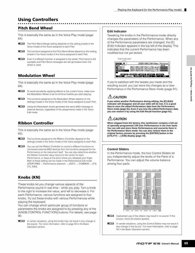
Playing the Keyboard (in the Performance Play mode)
Using Controllers
Qu
ick
Gu
ide
— P
layi
ng
th
e M
OT
IF E
S
Pitch Bend Wheel
This is basically the same as in the Voice Play mode (page 64).
n The Pitch Bend Range setting depends on the setting (made in the Voice mode) of the Voice assigned to each Part.
n The functions assigned to the Pitch Bend Wheel depend on the setting (made in the Voice mode) of the Voice assigned to each Part.
n Even if a different function is assigned to the wheel, Pitch bend is still available and Pitch Bend messages are still generated when the wheel is used.
Modulation Wheel
This is basically the same as in the Voice Play mode (page 64).
n To avoid accidently applying effects to the current Voice, make sure the Modulation Wheel is set to minimum before you start playing.
n The functions assigned to the Modulation Wheel depend on the settings (made in the Voice mode) of the Voice assigned to each Part.
n Using the Modulation wheel generates the same MIDI message to external devices, regardless of the assignments made in the Voice Edit mode.
Ribbon Controller
This is basically the same as in the Voice Play mode (page 65).
n The functions assigned to the Ribbon Controller depend on the settings (made in the Voice mode) of the Voice assigned to each Part.
n You can set the Ribbon Controller to control a different functions on connected external MIDI devices from the functions assigned for the Performance on the instrument itself. You can also determine whether the Ribbon Controller value returns to the center for each Performance, or stays at the point where you released your finger. Both of these setting can be made in the Performance Edit mode ([PERFORM] → Performance selection → [EDIT] → COMMON → [F4] CTL ASN).
Knobs (KN)
These knobs let you change various aspects of the Performance sound in real time – while you play. Turn a knob to the right to increase the value, and left to decrease it. For each Performance, various functions are assigned to four knobs. Try out these knobs with various Performances while playing the keyboard. You can change which particular group of functions or parameters the knobs are assigned to by pressing any of the [KNOB CONTROL FUNCTION] buttons. For details, see page 90.
n In certain situations, using the knobs may not result in any change in the sound. For more information, refer to page 50 in the Basic Operation section.
Edit IndicatorTweaking the knobs in the Performance mode directly changes the parameters of the Performance. When any of the Performance parameters are changed, the [E] (Edit) Indicator appears in the top left of the display. This indicates that the current Performance has been modified but not yet stored.
If you’re satisfied with the tweaks you made and the resulting sound, you can store the changes as a User Performance in the Performance Store mode (page 91).
If you select another Performance during editing, the [E] (Edit) indicator will disappear and all your edits will be lost. It is a good idea to store the edited Performance data from the Performance Store mode (page 91). Even if you lose the edited Performance data, you can restore it by using the Edit Recall function (page 91).
When shipped from the factory, this synthesizer contains a full set of specially programmed 128 User Performances in the User bank. You can edit and store these Performances and overwrite them in the Performance Store mode. You can also restore them to the original factory presets by pressing the [ENTER] button in the [UTILITY] →→→→ [JOB] display (page 44).
Control SlidersIn the Performance mode, the four Control Sliders let you independently adjust the levels of the Parts of a Performance. You can adjust the volume balance among four parts.
n Inadvertent use of the sliders may result in no sound. If this occurs, move the sliders upward.
n In certain situations, using the Control Sliders may not result in any change in the sound. For more information, refer to page 50 in the Basic Operation section.
Edit Indicator
CAUTION
CAUTION
ZONE 1
CS 1
VOLUME 1
ZONE 1
VOLUME 1
ZONE 1
VOLUME 1
ZONE 1
VOLUME 1
ZONE 1
CS 1
VOLUME 1 VOLUME 2 VOLUME 3 VOLUME 4
CS 2
ZONE 2
CS 3
ZONE 3
CS 4
ZONE 4
69Owner’s Manual

Playing the Keyboard (in the Performance Play mode)
70
Qu
ick Gu
ide —
Playin
g th
e MO
TIF
ES
Using the Arpeggio feature
As in the Voice mode, you can use the Arpeggio feature in the Performance mode. In the Performance mode, you can make independent Arpeggio playback settings for each Part of the Performance — including the on/off setting, as well as the Arpeggio type and related parameters. This means you can set the Performance such that any or all Parts can be used to trigger Arpeggio playback. A useful application of this would be to assign a Drum Voice to one Part and use Arpeggio playback on only that Part — so that you can have a rhythm pattern accompaniment playing while you play another Voice.Since the preset Performances already have their own Arpeggio types pre-assigned, all you need to do is select the desired Performance and turn on the Arpeggio function. Try selecting different Performances and check out the various Arpeggio types.
n Different Arpeggio types cannot be played back for each Part.
n For details about Arpeggio, see page 169.
■ Changing the Arpeggio type during your performanceAs in the Voice Play mode (page 66), the Performance play mode lets you use the [SF1] - [SF5] buttons to assign the Arpeggio types and recall them. The Arpeggio type for the current Performance can be selected in the [PERFORM] → [F6] ARP display or the [PERFORM] → [EDIT] → [COMMON] → [F3] ARP display. If you assign the desired Arpeggio type to the [SF1] - [SF5] buttons, store the settings as a User Performance in the Performance Store mode (page 91).
■ Controlling Arpeggio playback by using the knobsYou can tweak Arpeggio related parameters such as volume and tempo by using the knobs. If you’re satisfied with the tweaks you made and the resulting sound, you can store the changes as a User Performance in the Performance Store mode. For information on using the knobs, refer to the Voice Play mode (page 66).
Assigning desired Voices to each part
Performances can be made up of a maximum of four Parts (Voices), selected from the internal tone generator Parts 1 - 4 and Plug-in board Parts 1 - 3.You can create a Performance by layering several Voices together, and by assigning different Voices to separate ranges of the keyboard. You can then store up to 128 of your original, edited Performances to internal User memory.
1 2 3 4 PLG1 PLG2 PLG3 1 2 3 4 PLG1 PLG2 PLG3
Built-in tone generator Parts
Layer (example) Split (example)
Plug-in Parts*
*Available when the Plug-in Board has been installed.
Built-in tone generator Parts Plug-in Parts*
Ow
ner’s Man ual
Playing the Keyboard (in the Performance Play mode)
Qu
ick
Gu
ide
— P
layi
ng
th
e M
OT
IF E
S
This calls up a list indicating which Voice is assigned to each Part of the current Performance.
Move the cursor to the desired Part. When a Voice has already been assigned to the selected Part, change the Voice Bank or Number by using the data dial, the [INC/YES] and the [DEC/NO] button. When no Voice is assigned to the selected Part, press the [SF1] ADD INT button or [SF2] ADD PLG button to execute the assignment, then change the Voice Bank or Number. You can also select a Voice Bank/Number by using the BANK, GROUP, and NUMBER buttons (page 60).
n Voices of the Multi part Plug-in Board PLG100-XG cannot be assigned to Performance parts.
1 Press the [F2] VOICE button in the Performance Play mode.
2 Assign the desired Voice to each Part.
SCENESF1 SF2 SF3 SF4 SF5
F1 F2 F3 F4 F5 F6
INFORMATION
SCENESF1 SF2 SF3 SF4 SF5
F1 F2 F3 F4 F5 F6
INFORMATION
DEC/NO INC / YES
Select a Voice Bank/Number at the cursor location.
Voice Bank Voice Number
Assign an internal Voice to the selected Part.
Delete the Voice assignment of the selected Part.
Assign a Plug-in Voice to the selected Part. (Available when the Plug-in Board has been installed.)
When an internal Voice is assigned to a Part, the following Voice Banks are available.
When a Plug-in Board Voice is assigned to a Part, the available Voice Banks differ depending on the installed Plug-in Board. For details, refer to the Owner’s Manual that came with the Plug-in Board.
You can set the lowest note of the range over which the Voice of the selected Part sounds by simultaneously holding the [SF4] button and pressing the desired key. To set the highest note of the range, simultaneously hold the [SF5] button and press the desired key.
Press the [STORE] button to enter the Performance Store mode, select the destination Performance number, then press the [ENTER] button to execute the store operation. For details about Performance Store, see page 91.
PRE1 (Preset1) ~ PRE6 (Preset 6)
Preset Banks 1 - 6 of the Normal Voice. These correspond to the [PRE1] - [PRE6] buttons in the Voice mode.
USER1 ~ USER2 User Banks 1 - 2 of the Normal Voice. These correspond to the [USER1] - [USER2] buttons in the Voice mode.
GM GM Normal Voice Bank. This corresponds to the [GM] button in the Voice mode.
PDR (Preset Drum) Preset Bank of the Drum Voice. This corresponds to pressing the [DRUM KITS] button and the [PRE5] button simultaneously.
GMDR (GM Drum) GM Drum Voice Bank. This corresponds to pressing the [DRUM KITS] button and the [GM] button simultaneously.
UDR (User Drum) User Bank of the Drum Voice. This corresponds to pressing the [DRUM KITS] button and the [USER1] button simultaneously.
3 Specify the note range of each part, as required.
4Change the volume of each Part and adjust the relative balance among the four Parts by using the Control sliders.
5 Store the settings as a User Performance in the Performance Store mode.
SF 4 SF 5
Note Limit Low Note Limit High
71Owner’s Manual

Qu
ick Gu
ide —
Playin
g th
e MO
TIF
ES
Playing the Keyboard (in the Performance Play mode)
72
Using the A/D input sound
One of the enormous benefits of the Performance mode is that you can have the A/D input sound — such as your voice through a microphone, a guitar, bass, or CD player — assigned as one of the four Parts of a Performance. Various Part parameters such as volume, pan, and effects can be set for this Part, and the sound of the Part is mixed and output together with the other Parts. These parameters are set and stored in the Performance Store mode for each Performance.
n The Audio Input part is available also in the Song mode/Pattern mode, but is not available in the Voice mode. The procedure and explanations here apply to the Song and Pattern modes as well. The microphone related parameters (corresponding to step #8 below) of each Song/Pattern are edited in the Song Mixing mode/Pattern Mixing mode.
Connecting a microphone to the A/D INPUT jack
The explanation below applies in particular to low-level equipment, such as microphones, guitars and basses.
n A standard dynamic microphone is recommended. (The MOTIF ES does not support phantom-powered condenser microphones.)
1Make sure to turn the power of the MOTIF ES off and set the GAIN knob on the rear panel to the minimum.
2 Plug the microphone to the A/D INPUT jack on the rear panel.
3 Turn the power on.
4Press the [PERFORM] button to enter the Performance Play mode and select the desired Performance.
A /D INPUTLR
GAIN
Owner’s Manual
Move the cursor to the “Mic/Line” parameter by using the Cursor button and set it to “mic” by using the [INC/YES] button, [DEC/NO] button, or data dial.
n When the output level of the connected equipment (such as a microphone, guitar, bass) is low, set this parameter to “mic.” When the output level of the connected equipment (such as a synthesizer keyboard, CD player) is high, set this parameter to “line.”
n This setting is available for all modes. If you wish to store this setting, press the [STORE] button.
5Press the [UTILITY] button to enter the Utility mode, press the [F2] I/O button, then press the [SF1] INPUT button.
6 Set Mic/Line to “mic.”
SONG PATTERN FILE
SEQUENCER
INTEGRATEDSAMPLING MIXING UTILITY
DEMO
SCENESF1 SF2 SF3 SF4 SF5
F1 F2 F3 F4 F5 F6
INFORMATION

Playing the Keyboard (in the Performance Play mode)
Qu
ick
Gu
ide
— P
layi
ng
th
e M
OT
IF E
S
For details about each parameter, refer to page 214 in the Reference section.
Connecting audio equipment to the A/D INPUT jack
The explanation below applies in particular to high-level audio equipment, such as CD players, synthesizers, and other keyboards.
7 Adjust the microphone input level by using the GAIN knob on the rear panel.
8Set the audio input related parameters as necessary from the AUDIO IN display ([PERFORM] →→→→ [EDIT] →→→→ [COMMON] →→→→ [F5] AUDIO IN).
9 Store the settings as a User Performance in the Performance Store mode (page 91).
1 Make sure to turn off the power of both the MOTIF ES and the relevant audio equipment.
2 Plug the audio equipment cable to the A/D INPUT jack on the rear panel.
3Switch the power of the connected audio equipment on, then switch the power of the MOTIF ES on.
A /D INPUTLR
GAIN
When the optional AIEB2 or mLAN16E has been installed, the [F5] AUDIO IN menu has two indications: “A/D” and “AIEB2” or “mLAN16E.” Here, call up the A/D display by pressing the [SF5] button.
A /D INPUTLR
L R
GAIN
Move the cursor to the “Mic/Line” parameter by using the Cursor button and set it to “line” by using the [INC/YES] button, [DEC/NO] button, or data dial.
n When the output level of the connected equipment (such as a microphone, guitar, bass) is low, set this parameter to “mic.” When the output level of the connected equipment (such as a synthesizer keyboard, CD player) is high, set this parameter to “line.”
n This setting is available for all modes. If you wish to store this setting, press the [STORE] button.
For details about each parameter, refer to page 214 in the Reference section. When an optional AIEB2 or mLAN16E has been installed, press the [SF5] button to call up the A/D display.
n Audio input signals from the OPTICAL INPUT and DIGITAL INPUT connector (when the optional AIEB2 has been installed) or the mLAN connector (when the optional mLAN16E has been installed) can also be handled as Audio Input Parts. For details, see page 165.
4Press the [PERFORM] button to enter the Performance Play mode and select the desired Performance.
5Press the [UTILITY] button to enter the Utility mode, press the [F2] I/O button, then press the [SF1] INPUT button.
6 Set Mic/Line to “line.”
7 Adjust the audio input level by using the GAIN knob on the rear panel.
8Set the audio input related parameters as necessary from the AUDIO IN display ([PERFORM] →→→→ [EDIT] →→→→ [COMMON] →→→→ [F5] AUDIO IN).
9 Store the settings as a User Performance in the Performance Store mode (page 91).
A /D INPUTLR
L R
GAIN
73Owner’s Manual

Qu
ick Gu
ide —
Playin
g th
e MO
TIF
ES
Using the Plug-in Board
74
Using the Plug-in BoardPlug-in Boards give you an enormous amount of additional sonic flexibility and power. When installed, they work seamlessly and transparently within the system of this synthesizer – meaning that you can use their sounds and functions just as if they were built right into this synthesizer at the factory.The boards that are available for and can be installed to this synthesizer are described below.Up to three Plug-in boards can be installed to the MOTIF ES. These boards are not simply a source of more Voices; they are also full-featured, editable tone generators in their own right and extend the system-level specifications such as maximum polyphony.In addition, they allow you to use synthesis systems besides AWM2. You can play Plug-in Voices just like ordinary internal Voices and use them as Parts in a Song/Pattern/Performance. This synthesizer is compatible with the Modular Synthesis Plug-in System (see below).
About MODULAR SYNTHESIS PLUG-IN SYSTEMThe Yamaha Modular Synthesis Plug-in System offers powerful expansion and upgrade capabilities for Modular Synthesis-Plug-in-compatible synthesizers, tone generators and sound cards. This enables you to easily and effectively take advantage of sophisticated synthesizer and effects technology, allowing you to keep pace with the rapid and multi-faceted advances in modern music production.
Available Plug-in Boards
There are three types of Modular Synthesis Plug-in System-compatible Plug-in Boards: Single Part, Multi-Part and Effect Plug-in Board. Using these, you can build your own system based on the sounds you require.
● Drum Plug-in Board (PLG150-DR)/Percussion Plug-in
Single Part Plug-in BoardsSingle Part Plug-in Boards let you add a completely different synthesizer or single timbre tone generator (page 162) and play its voices by using a single part of this synthesizer. Some boards allow you to use synthesis systems besides AWM2.
● Analog Physical Modeling Plug-in Board (PLG150-AN)Using Analog Physical Modeling (AN) synthesis, the very latest digital technology is used to accurately reproduce the sound of analog synthesizers. With this board installed, you have real-time control over the playback of vintage synthesizer sounds as well as the very latest sounds heard in today’s club-oriented music.
● Piano Plug-in Board (PLG150-PF)A massive waveform memory is dedicated to the reproduction of piano sounds. This board offers 136 stereo sounds, including a number of acoustic and electric pianos, and up to 64-note polyphony. You can even install two of these boards to double the polyphony to 128 notes.
● Advanced DX/TX Plug-in Board (PLG150-DX)The sounds of the DX7 are available on this Plug-in Board. Unlike PCM-based tone generators, this board uses the powerful FM Synthesis system – the same as found on DX-series synthesizers – for extraordinarily versatile and dynamic sound shaping potential. Sounds are compatible with those of the DX7, and the board can even receive DX7 data via MIDI bulk dump.
● Virtual Acoustic Plug-in Board (PLG150-VL)With Virtual Acoustic (VA) synthesis, the sounds of real instruments are modeled (simulated) in real time, giving a degree of realism that cannot be achieved using conventional PCM-based synthesis techniques. When playing these sounds using an optional MIDI Wind Controller (WX5), you can even capture some of the physical feel of woodwind instruments.
Owner’s Manual
Board (PLG150-PC)Once connected and installed, the PLG150-DR/PLG150-PC becomes a seamless additional sound source of AWM2 for the host tone generator or synthesizer – providing a total of 88 drum/percussion voices. Thanks to the built-in effect processing power, the PLG150-DR/PLG150-PC has two separate effect blocks – Insertion and Reverb – that can be applied to each kit.
Multi-Part Plug-in Board
Multi-Part Plug-in Boards let you add a completely independent multi-timbral tone generator to the MOTIF ES (page 162) — expanding the Voice capacity and polyphony of the instrument with a full sixteen additional instrument parts.
● XG Plug-in Board (PLG100-XG)This Plug-in Board is a 16-part XG sound generator. You can play back XG/GM song files using the rich variety of sounds and effects on this board.
Effect Plug-in Board
Effect Plug-in Boards let you add a completely different effect block to the host synthesizer.
● Vocal Harmony Plug-in Board (PLG100-VH)With this board installed, you can add harmonies to selected parts using four types of effects. Chorus parts for vocals can be created automatically from chords that have been prepared and stored as MIDI data. You can also use this synthesizer like a vocoder by connecting and using a microphone while playing the keyboard.

Using the Plug-in Board
Using a Single Part Plug-in Board
Install any of the Single Part Plug-in Boards such as PLG150-AN, PLG150-PF, PLG150-DX, PLG150-VL, PLG150-DR, and PLG150-PC to the MOTIF ES and play the Plug-in Voice in the Voice Play mode.
Qu
ick
Gu
ide
— P
layi
ng
th
e M
OT
IF E
S
See page 283.
The corresponding slot indicator at the right top of the front panel lights. This indicates that the board has been successfully installed.
1 After turning the power off, install a Single Part Plug-in Board to the instrument.
2 Switch the MOTIF ES on.
3Check the status of the installed Plug-in Boards in the [UTILITY] → [F6] PLUG → [SF1] STATUS display.
STRINGS
PLG 1
SLOT 1 SLOT 2 SLOT 3
BRASS
PLG 2
REED/PIPE
PLG 3
SCENESF1 SF2 SF3 SF4 SF5
F1 F2 F3 F4 F5 F6
INFORMATION
VOICE
SONG
PERFORM MASTER
PATTERN FILE
MODE
SEQUENCER
INTEGRATEDSAMPLING MIXING UTILITY
DEMO
The name of the installed Plug-in Board is displayed.
n If the MIDI Port number here is set to “1” or “off,” the Plug-in Voice may sound simultaneously with the internal Voice, when playing back Song/Pattern data. To keep this from happening, make sure the MIDI Port number of the Plug-in Board is set to “2” or “3” — especially when using the Song/Pattern mode. To prevent a similar problem when using both a Single Part Plug-in Board and a Multi Part Plug-in Board together, set each board to a different MIDI Port number.
Selecting a Plug-in Voice is done in the same way as selecting a Normal Voice (page 60) with the exception that you select one of the PLG (Plug-in) Banks. Press the PLG button which corresponds to the slot to which the Plug-in Board has been installed.
You’ll also need to select a Bank within the Plug-in Board. Press the [F2] BANK button to call up the Plug-in Board Bank selection display, then select the desired Bank.
n For details about the Bank structure of each Plug-in Board, refer to the Owner’s Manual of each Plug-in Board. Regarding the PLGPRE (Plug-in Preset) bank, refer to the Plug-in Voice List. Regarding the Board Voice bank displayed as “035/000,” refer to the the Voice Map/List. The PLGUSR (Plug-in User) banks contain the Voices you edited and stored as User Voices.
n Playing Voices of the Plug-in User banks (PLG1USR, PLG2USR, PLG3USR) will result in no sound, if the Plug-in Board has just been installed. These banks become available only after you edit a Plug-in Voice and store it as a User Plug-in Voice.
4Set the MIDI port of the installed Plug-in Board to “2” or “3” in the [UTILITY] → [F6] PLUG → [SF2] MIDI display.
5 Press the [VOICE] button to enter the Voice Play mode and select a Plug-in Voice.
6 Play the keyboard.
STRINGS
PLG 1
SLOT 1 SLOT 2 SLOT 3
BRASS
PLG 2
REED/PIPE
PLG 3
75Owner’s Manual

Qu
ick Gu
ide —
Playin
g th
e MO
TIF
ES
Using the Plug-in Board
76
Plug-in Voices and Board VoicesThe Voices of a Single Part Plug-in Board installed to this synthesizer can be divided into two types: Board Voices and Plug-in Voices. Board Voices are unprocessed, unaltered Voices of the Plug-in board – the “raw material” used for the Plug-in Voices. Plug-in Voices, on the other hand, are edited Board Voices – Voices that have been specially programmed and processed for optimum use with the host synthesizer. Since the MOTIF ES includes preset Plug-in Voices for all the Plug-in Boards, you can call up and play appropriate Voices for each board immediately after installing it.
n The Plug-in Voices can be edited in the Voice Edit mode.
n The Board Voices can be edited using the computer software supplied for each Plug-in Board.
Playing the PLG150-VL sound with the Breath Controller
With Virtual Acoustic (VA) synthesis, the PLG150-VL has the sounds of real instruments modeled (simulated) in real time, giving a degree of realism that cannot be achieved using conventional PCM-based synthesis techniques. When playing these sounds using an optional Breath Controller, you can even capture some of the physical feel of woodwind instruments.
6 Press the [VOICE] button to enter the Voice Play
TIP
1 Install the PLG150-VL to the MOTIF ES.
2 Connect the Breath Controller BC3 to the BREATH connector on the rear panel (page 42).
3 Switch the MOTIF ES power on.
4 Set the Plug-in Board related parameters in the Utility mode, corresponding to steps #3 and 4 in the instructions on the previous page.
5 Set the Breath Controller Curve via the [UTILITY] → [F1] GENERAL → [SF1] TG → BCCurve parameter (page 260).
BREATH ASSIGNABLE SUSTAIN
FOOTSWITCH
Owner’s Manual
mode, then select a Plug-in Voice of the PLG150-VL.
7 Play the Voice and blow into the Breath Controller to expressively change the sound.
You can also use the MIDI Wind Controller WX5 to play the Plug-in Voice of the PLG150-VL. Connect the WX5 to the MOTIF ES with a MIDI cable.
WX5
MIDI OUT connector
MIDI IN connectorMIDI cable
MOTIF ES
MUSIC PRODUCTION SYNTHESIZER

Using the Plug-in Board
Using a Multi Part Plug-in Board
In this section, we’ll explain how to play back an XG format song, using the PLG100-XG Plug-in Board. Naturally, to get the most out of these instructions, you should have XG song data (Standard MIDI File) stored on a SmartMedia card or USB storage device.
Qu
ick
Gu
ide
— P
layi
ng
th
e M
OT
IF E
S
See page 283 for details.
n If the MIDI Port number here is set to “1” or “off,” the Plug-in Voice may sound simultaneously with the internal Voice, when playing back Song/Pattern data. To keep this from happening, make sure the MIDI Port number of the Plug-in Board is set to “2” or “3” — especially when using the Song/Pattern mode. To prevent a similar problem when using both a Single Part Plug-in Board and the PLG100-XG together, set each board to a different MIDI Port number.
1 Insert a SmartMedia card which contains the XG song files into the CARD slot, or use a USB storage device (connected to the USB TO DEVICE connector) containing appropriate XG song files.
1After turning the power off, install the Multi Part Plug-in Board PLG100-XG to slot 3 of this synthesizer.
2 Switch the MOTIF ES power on.
3Check the status of the installed Plug-in Boards in the [UTILITY] → [F6] PLUG → [SF1] STATUS display.
4Set the MIDI port of the PLG100-XG to “2” or “3” in the [UTILITY] → [F6] PLUG → [SF2] MIDI display.
5Press the [SONG] button to enter the Song mode, then press the [FILE] button to enter the File mode.
6Load the XG song file (Standard MIDI file) from the SmartMedia/USB storage device to the MOTIF ES in the [FILE] → [F3] LOAD display, as described in the sub-instructions below.
The name of the installed Plug-in Board is displayed.
2 Press the [FILE] button to enter the File mode, then set the basic parameters. Refer to “Basic settings for using SmartMedia or a USB storage device” on page 30.
3 Set the [FILE] → [F3] LOAD → TYPE parameter to “Song.”
4 Move the cursor to the list of files to be loaded, select the desired file, then press the [ENTER] button.
5 Specify the destination Song number, then press the [ENTER] button to execute the Load operation.
Loading data to this synthesizer automatically erases and replaces any existing data in the User memory. Make sure to save any important data to a SmartMedia/USB storage device before performing any Load operations.
7Press the [SONG] button to enter the Song Play mode, then select the Song number to which the XG song file was loaded.
8Set the MIDI transmit port of all the tracks to the number set in step #4 from the [SONG] → [F3] TRACK → [SF1] CHANNEL display.
9 Press the [FFFF] (Play) button to play the XG song.
File/folder list
CAUTION
Set MIDI transmit ports.
77Owner’s Manual

Qu
ick Gu
ide —
Playin
g th
e MO
TIF
ES
Using the Plug-in Board
78
Using an Effect Plug-in Board
In the example explanation below, the PLG100-VH Vocal Harmony Plug-in Board is used to apply harmony effects to the microphone sound in the Performance mode.
n For Songs/Patterns, the Effect Plug-in Board related parameters (which correspond to step #6 - 7 below) can be edited in the Song Mixing mode/Pattern Mixing mode.
n Please note that the Effect Plug-in Board cannot be used in the Voice mode.
See page 283 for details.
n A standard dynamic microphone is recommended. (The MOTIF ES does not support phantom-powered condenser microphones.)
For details, refer to steps #4 - 9 on page 72.
1 After turning the power off, install the Effect Plug-in Board PLG100-VH to slot 1.
2 Plug the microphone to the A/D INPUT jack on the rear panel (page 72).
3 Turn the MOTIF ES power on.
4Press the [PERFORM] button to enter the Performance Play mode, select the desired Performance, then set the microphone related parameters.
5Check the status of the installed Plug-in Boards in the [UTILITY] → [F6] PLUG → [SF1] STATUS display.
6Select “PartAD” as the Part to which the Plug-in Insertion Effect is applied in the CONNECT display ([PERFORM] →→→→ [F3] EFFECT →→→→ [SF1] CONNECT).
A /D INPUTLR
GAIN
Move the cursor here, then select the Part.
Owner’s Manual
For details, refer to the Owner’s Manual of the PLG100-VH.
7Set related parameters (such as the Effect Type, and others) from the Plug-in Effect display ([PERFORM] → [EDIT] → [COMMON] → [F6] EFFECT → [SF3] PLG-EF).
8Sing or talk into the microphone to check the effect sound, and adjust the settings as necessary.
9If desired, store the settings for the microphone sound and PLG100-VH as a Performance in the Performance Store mode (page 91).
A /D INPUTLR
GAIN

Editing a Voice
Qu
ick
Gu
ide
— A
dva
nce
d C
ou
rse
Editing a VoiceThe Voice Edit mode ([VOICE] → [EDIT]) gives you comprehensive tools for creating your own original Voices, either from scratch by changing the basic sounds, or by tweaking the various Voice parameters. Create your custom sounds by calling up a preset Voice and editing as desired. The actual parameters available and the methods for editing differ depending on the Voice type.
● Normal Voice EditA Normal Voice can consist of up to four Elements. There are two types of Voice Edit displays: those for Common Edit to edit the settings common to all four Elements, and those for editing individual Elements.
● Drum Voice EditEach Drum voice consists of various Waves and/or Normal voices, each assigned to notes across the keyboard, from C0 to C6. There are two types of Drum Voice Edit displays: those for Common Edit to edit the settings that apply to all Drum keys in the voice, and those for editing individual keys (Elements).
● Plug-in Voice EditThis is basically the same as Normal Voice Edit. Unlike with Normal voices, the Plug-in voices only have one Element for editing.
Normal Voice Edit
If you wish to edit the sounds that make up a Voice and the basic parameters that determine the sound, such as Oscillator, Pitch, Filter, Amplitude, and EG (Envelope Generator), call up the Element Edit display. If you wish to edit more global parameters related to the overall Voice and how it’s processed, such as Arpeggio, Controller, and Effects, call up the Common Edit display.
Quick Guide — Advanced Course
1 Press the [VOICE] button to enter the Voice mode, then select a Normal Voice to be edited.
2 Press the [EDIT] button to enter the Voice Edit mode.
3 Call up the Common Edit display or Element Edit display.
EDIT
COMPARE SCENE STORESET LOCATE
JOB STORE
COMMON ELEMENT/PERF. PART/ZONE
FAVORITES
DRUM KITS
A. PIANO KEYBOARD ORGAN
PRE 5 PRE 6 USER 1
GUITAR/PLUCKED
SYN LEAD
A B C D
4321
1211109
SYN PAD/CHOIR
SYN COMP CHROMATICPERCUSSION
USER 2Calling up the Common Edit displayPress the [COMMON] button to call up the Common Edit display.
In the Edit mode, the [DRUM KITS] button functions as the [COMMON] button.
While in the Voice Edit mode, you can switch between the Common Edit display and the Element Edit display as shown below.
Indicates a Common Edit display.
Calling up the Element Edit displayPress the desired element number from the ELEMENT [1] - [4] buttons to call up the Element Edit display.
Indicates the display for editing Element 1.
Common Edit
Element Edit 1Element Edit 2
Element Edit 3Element Edit 4
To turn each Element on or off (to hear how each affects the overall sound), use buttons [9] - [12]. You can also isolate or solo an Element by holding down the [MUTE] button and pressing the desired number button ([9] - [12]). To cancel the solo, press the [MUTE] button again.
79Owner’s Manual

Editing a Voice
80
Qu
ick Gu
ide —
Ad
vanced
Co
urse
The following briefly describes the main Voice parameters.
● Basic parameters for creating a sound
If you wish to edit the basic sound-generating and sound-shaping parameters for the Voice, such as Oscillator, Pitch, Filter, Amplitude, and EG (Envelope Generator), use the Common Edit display.
● Effect related parameters.................... Pages 177 and 194
The Effects use DSP (Digital Signal Processing) to alter and enhance the sound of a Voice. Effects are applied in the final stages of editing, letting you change the sound of the created Voice as desired. The Common Edit display lets you edit the Effect related parameters.
● Controller related parameters ........... Pages 155 and 192
For each Voice, you can assign various functions to built-in controllers such as Pitch Bend Wheel, Modulation Wheel, Ribbon Controller, Knobs (ASSIGN1 and 2), Keyboard Aftertouch and optionally connected controllers such as Footswitch, Foot Controller, Breath Controller. These settings can be edited in the Common Edit display.
● Arpeggio related parameters............. Pages 169 and 191
For each Voice, you can set the Arpeggio related parameters such as Arpeggio type and playback tempo. These can be edited in the Common Edit display.
Enter a name for the Voice from the NAME display ([COMMON] → [F1] GENERAL → [SF1] NAME). For detailed instructions on naming, refer to page 53 in the Basic Operation section.
4Select the menu you wish to edit by pressing the [F1] - [F6] and [SF1] - [SF5] buttons, then edit the parameters.
Element selection →→→→ [F1] - [F6]
[F1] OSC (Oscillator) pages 160, 195
[F2] PITCH pages 160, 196
[F3] FILTER pages 161, 197
[F4] AMP (Amplitude) pages 162, 199
[F5] LFO pages 162, 201
[F6] EQ (Equalizer) pages 178, 201
[COMMON] →→→→ [F6] EFFECT
[COMMON] → [F3] ARP (Arpeggio)
5 Repeat #3 - 4 as desired.
6 Name the edited Normal Voice.
Enter the desired Voice name.
Owner’s Manual
The edited Voice can be stored in the Voice Store mode. See page 85 for details.
Keep in mind that edited Voice data is stored to internal User memory (Flash ROM) and is stored even when turning the power off. As such it is not necessary to save the data to SmartMedia card or another device; however, you may want to save it to another media for backup or organizational purposes. For more information, see page 85.
Compare FunctionThis convenient function lets you switch between the edited Voice and its original, unedited condition – allowing you to listen to the difference between the two and better hear how your edits affect the sound.
1 In the Voice Edit mode (the [EDIT] indicator lighting), press the [EDIT] button so that its indicator flashes.The [C] indicator is shown at the top of the display (in place of the [E] indicator), and the original, unedited voice is restored for monitoring.
2 Press the [EDIT] button again to disable the “Compare” function and restore the settings for your edited Voice.
Compare the edited sound with the unedited sound by repeating steps #1 and 2.
n While Compare is active, you cannot make edits to the Voice.
7 Store the edited Voice to internal User memory (page 186).
8 If desired, save the edited and stored voices to a SmartMedia/USB storage device.
EDIT
COMPARE SCENE STORESET LOCATE
JOB STORE

Editing a Voice
Qu
ick
Gu
ide
— A
dva
nce
d C
ou
rse
Editing a Voice by using the KnobsThe four knobs at the top left of the instrument are not only for tweaking the sound while you perform — you can also use them to edit a Voice, either in the Voice Play mode or the Voice Edit mode.
● When the [PAN/SEND] indicator is turned on:
● When the [TONE] indicator is turned on:
n The settings above are applied as offsets to the AEG and FEG settings in the Voice Edit mode.
● When the [ARP FX] indicator is turned on:
● When the [EQ] indicator is turned on:
n The settings above are applied as offsets to the EQ settings in the [VOICE] → [UTILITY] → [F3] VOICE → [SF1] MEQ display.
● When both the [PAN/SEND] and [TONE] indicators are turned on (by pressing them simultaneously):
n In addition to above functions, Master Effect related parameters (set in the [UTILITY] → [F3] VOICE → [SF2] MEF display) can be assigned to these four knobs by pressing the [ARP FX] and [EQ] buttons simultaneously. The particular parameters assigned to the four knobs can be set in the [UTILITY] → [F4] CTL ASN → [SF5] MEF display.
Editing a Voice by using the Control Sliders (CS)
In the Voice mode, the four Control Sliders let you independently adjust the levels of the Elements of a Normal Voice or the Drum Voice keys. When a Normal Voice is selected, you can adjust the level balance among the four Elements.
n Inadvertent use of the sliders may result in no sound. If this occurs, move the sliders upward.
PAN Determines the stereo pan position of the Voice. [VOICE] → Voice selection → [EDIT] → [COMMON] → [F2] OUTPUT → Pan
Page 190
REVERB Determines the amount of Reverb effect that is applied to the Voice. [VOICE] → Voice selection → [EDIT] → [COMMON] → [F2] OUTPUT → RevSend
Page 191
CHORUS Determines the amount of Chorus effect that is applied to the Voice. [VOICE] → Voice selection → [EDIT] → [COMMON] → [F2] OUTPUT → ChoSend
Page 191
TEMPO Determines the tempo of the Arpeggio assigned to the currently selected Voice. [VOICE] → Voice selection → [F6] ARP → Tempo Page 189
CUTOFF Raises or lowers the Filter cutoff frequency to adjust the tone brilliance. [VOICE] → Voice selection → [F5] EG → CUTOF Page 189
RESONANCE Boosts or attenuates the level at the area around the Filter cutoff frequency.
[VOICE] → Voice selection → [F5] EG → RESO Page 189
ATTACK Determines the attack time of the sound. For example, you can adjust a strings Voice so that the sound gradually swells in volume by setting a slow attack time – simply turn this knob to the right.
[VOICE] → Voice selection → [F5] EG → ATK (AEG) Page 189
RELEASE Determines the release time of the sound. Turning the knob to the right sets a long release time and (depending on the selected Voice) lets the sound sustain after the key is released. To produce a sharp release, in which the sound abruptly cuts off, set a short release time.
[VOICE] → Voice selection → [F5] EG → REL (AEG) Page 189
SWING Adjusts the swing feel of the Arpeggio playback. [VOICE] → Voice selection → [EDIT] → [COMMON] → [F3] ARP → [SF3] PLAY FX → Swing
Page 192
GATE TIME Adjusts the Gate Time (length) of the Arpeggio notes. [VOICE] → Voice selection → [EDIT] → [COMMON] → [F3] ARP → [SF3] PLAY FX → GateTimeRate
Page 192
VELOCITY Adjusts the velocity of the Arpeggio notes. [VOICE] → Voice selection → [EDIT] → [COMMON] → [F3] ARP → [SF3] PLAY FX → VelocityRate
Page 192
UNITMULTIPLY Adjusts the Arpeggio playback time based on tempo. [VOICE] → Voice selection → [EDIT] → [COMMON] → [F3] ARP → [SF3] PLAY FX → UnitMultiply
Page 192
LO Determines the amount of boost or attenuation applied to the low frequency band of the Master EQ.
[VOICE] → Voice selection → [EDIT] → [COMMON] → [F1] GENERAL → [SF3] MEQ OFS → LOW
Page 190
LO MID Determines the amount of boost or attenuation applied to the low-midrange frequency band of the Master EQ.
[VOICE] → Voice selection → [EDIT] → [COMMON] → [F1] GENERAL → [SF3] MEQ OFS → LOW MID
Page 190
HI MID Determines the amount of boost or attenuation applied to the high-midrange frequency band of the Master EQ.
[VOICE] → Voice selection → [EDIT] → [COMMON] → [F1] GENERAL → [SF3] MEQ OFS → HIGH MID
Page 190
HI Determines the amount of boost or attenuation applied to the high frequency band of the Master EQ.
[VOICE] → Voice selection → [EDIT] → [COMMON] → [F1] GENERAL → [SF3] MEQ OFS → HIGH
Page 190
ASSIGN A Adjusts parameters assigned to these knobs in the [UTILITY] → [F4] CTL ASN → [SF2] ASSIGN display. Page 263
ASSIGN B
ASSIGN 1 Adjusts parameters assigned to these knobs in the [VOICE] → Voice selection → [EDIT] → [COMMON] → [F4] CTL SET display. Page 192
ASSIGN 2
[VOICE] → Voice selection → [EDIT] → Element selection → [F4] AMP → [SF1] LVL/PAN → Level
TIP
TIP
81Owner’s Manual

Editing a Voice
82
Qu
ick Gu
ide —
Ad
vanced
Co
urse
To solo an Element for editingThis feature is useful for isolating the sound of single Element, for ease in editing.
1 In the Normal Voice Edit mode, simultaneously hold down the [MUTE] button and press one of the NUMBER buttons [9] to [12] to solo the corresponding Element.Once you’ve selected an Element for soloing, the [MUTE] button’s lamp flashes, indicating the Solo function is active and only the selected Element can be edited.
2 To solo another Element, simply press the appropriate number button ([9] - [12]).
3 To exit from the Solo function, press the [MUTE] button again.
ELEMENT/PERF. PART/ZONE
87654321
16 MUTE
TRACKSELECT
NUMBER
SOLO
151412 1311109
In this example, only Element 3 is turned on and can be edited.
Owner’s Manual
Edit RecallIf you are editing a Voice and select a different Voice without storing the one you were editing, all the edits you’ve made will be erased. If this happens, you can use Edit Recall to restore the Voice with your latest edits intact.
1 Press the [JOB] button in the Voice mode to enter the Voice Job mode.
2 Press the [F2] RECALL button to call up the Recall display.
3 Press the [ENTER] button. (The display prompts you for confirmation.)If you wish to cancel the operation, press the [DEC/NO] button.
4 Press the [INC/YES] button to execute Edit Recall to restore the voice.
Drum Voice Edit
If you want to edit the sounds that make up a Drum Voice and the basic parameters that determine the sound, such as Oscillator, Pitch, Filter, Amplitude, and EG (Envelope Generator), call up the Key Edit display. To edit more global parameters related to the overall Drum Voice and how it’s processed, such as Arpeggio, Controller, and Effects, call up the Common Edit display.
1 Press the [VOICE] button to enter the Voice mode, then select a Drum Voice to be edited.
2 Press the [EDIT] button to enter the Voice Edit mode.
3 Call up the Common Edit display or Key Edit display.
EDIT
COMPARE SCENE STORESET LOCATE
JOB STORE
COMMON ELEMENT/PERF. PART/ZONE
FAVORITES
DRUM KITS
A. PIANO KEYBOARD ORGAN
PRE 5 PRE 6 USER 1
GUITAR/PLUCKED
SYN LEAD
A B C D
4321
1211109
SYN PAD/CHOIR
SYN COMP CHROMATICPERCUSSION
USER 2
C0
Key 1 Key 5 Key 10 Key 18 Key 21 Key 73
C1 C6
While in the Voice Edit mode, you can switch between the Common Edit display amd the Element Edit display as shown below.
Indicates a Common Edit display.
Common Edit
Calling up the Key Edit displayPress any of the ELEMENT [1] - [4] buttons to calll up the Key Edit display, then select the key to which the desired instrument is assigned.
Key Edit (1-73)
Indicates the display for editing the key C0.
Calling up the Common Edit displayPress the [COMMON] button to call up the Common Edit display. In the Edit mode, the [DRUM KITS] button functions as the [COMMON] button.

ick
Gu
ide
— A
dva
nce
d C
ou
rse
Editing a Voice
The main parameters available are basically the same as in the Normal Voice Edit (page 80). What is called Key Edit in the Drum Voice corresponds to Element Edit in the Normal Voice. Please keep in mind that the LFO parameters are not available in the Drum Voice.
Enter a name for the Voice from the NAME display ([COMMON] → [F1] GENERAL → [SF1] NAME). For detailed instructions on naming a voice, refer to page 53 in the Basic Operation section.
4Select the desired menu for editing by pressing the [F1] - [F6] and [SF1] - [SF5] buttons, then edit the parameters.
5 Repeat #3 - 4 as desired.
6 Name the edited Drum Voice.
Enter the desired Voice name.
The edited Voice can be stored in the Voice Store mode. See page 85 for details.
Keep in mind that edited Voice data is stored to internal User memory (Flash ROM) and is stored even when turning the power off. As such it is not necessary to save the data to SmartMedia card or another device; however, you may want to save it to another media for backup or organizational purposes. For more information, see page 85.
7 Store the edited Voice to internal User memory (page 186).
8 If desired, save the edited and stored voices to a SmartMedia/USB storage device.
Qu
Assigning drum/percussion instruments to individual keys
In the Drum Voice Edit mode, you can create your own original drum kits by assigning specific instrument sounds to individual keys — in any desired order — and edit detailed parameters for each key’s sound.
[VOICE] → Drum Voice selection → [EDIT] → Key selection → [F1] OSC → [SF1] WAVE
TIP
1 Call up the Key Edit display in the Voice Edit mode. Refer to step #3 on page 82.
2 Call up the [F1] OSC → [SF1] WAVE display.
3 Press the key to which you want to assign a sound.The drum instrument currently assigned to the pressed key will sound.
4 Select the desired Waveform to be assigned.Move the cursor to “Number” and change the value by using the data dial, [INC/YES] button, and [DEC/NO] button. Then, press the same key set in step #3 again to confirm the selected instrument sound.
5 Create your original drum kit by repeating steps #3 - 4.
6 Store the created drum kit as a Drum Voice in User memory. The edited Voice can be stored in the Voice Store mode. See page 85 for details.
7 If desired, save the edited and stored voices to a SmartMedia/USB storage device.
You can also select a different sound category (such as Percussion, or even a Normal Voice sound), by moving the cursor to “Category”and changing the setting.
83Owner’s Manual

Editing a Voice
84
Qu
ick Gu
ide —
Ad
vanced
Co
urse
Setting the drum key for independent open and closed hi-hat sounds
In a real drum kit, some drum sounds cannot physically be played simultaneously, such as open and closed hi-hats. You can prevent drum instruments from playing back simultaneously by assigning them to the same Alternate Group. The preset Drum Voices have many such Alternate Group assignments to ensure the most authentic, natural sound. When creating a Voice from scratch, you can use this feature — either to ensure authentic sound, or to create special effects, where playing one sound cancels out a previous one.
1 Call up the Key Edit display in the Voice Edit mode. 4 Press the key which corresponds to “Hi-Hat Close”
[VOICE] → Drum Voice selection → [EDIT] → Key selection → [F1] OSC → [SF5] OTHER → AltnateGroup
TIP
Refer to step #3 on page 82.
2 Call up the [F1] OSC → [SF5] OTHER display.
3 Press the key which corresponds to “Hi-Hat Open” and set the Alternate Group to “1.”
Owner’s Manual
and set it to the same Alternate Group (1) as in step #3.
5 Confirm whether the Alternate Group has been set properly. Immediately after pressing the “Hi-Hat Open” key, press the “Hi-Hat Close” key. Pressing the second key should cut off the sound of the first.
Since the settings above are included in the Drum Voice data, store them as a Drum Voice in the Voice Store mode.
Determining how the Drum Voice responds when the key is released
You can determine whether or not the selected Drum key responds to MIDI Note Off messages. Setting the Receive Note Off parameter to “off” can be useful for cymbal sounds and other sustaining sounds. This lets you have the selected sounds sustain to the length of their natural decay – even if you release the note, or when a Note Off message is received. If this parameter is set to “on,” the sound will stop immediately when the note is released or a Note Off message is received.
Setting the Output jack for each key (drum/percussion instrument)
You can change the output jack on the rear panel for the individual Drum key signal. This function is useful when you wish to apply a connected external effect to a specific drum instrument. For details, see page 31.
[VOICE] → Drum Voice selection → [EDIT] → Key selection → [F1] OSC → [SF5] OTHER → RcvNoteOff
[VOICE] → Drum Voice selection → [EDIT] → Key selection → [F1] OSC → [SF2] OUTPUT → OutputSel
TIP
TIP

Qu
ick
Gu
ide
— A
dva
nce
d C
ou
rse
Editing a Voice
Plug-in Voice Edit
The Plug-in Voices (available when installing optional Plug-in Boards to the instrument) can be edited in basically the same way as in Normal Voice Edit (page 79). Unlike with Normal voices, the Plug-in voices only have one Element for editing. In addition, some of the other parameters may not be available. Refer to page 205 in the Reference section.
Storing/Saving the created Voice
Two steps are necessary in order to store (save) your voice – storing the edited voice to internal memory and saving the stored voices to a SmartMedia/USB storage device.
Keep in mind that edited Voice data is stored to internal User memory (Flash ROM) and is stored even when turning the power off. As such it is not necessary to save the data to SmartMedia card or another device; however, you may want to save it to another media for backup or organizational purposes, using the Save operation. For more information, see page 86.
User Plug-in Voice 064
User Plug-in Voice 001User Plug-in Voice 002User Plug-in Voice 003
User Plug-in Voice 064
User Plug-in Voice 001User Plug-in Voice 002User Plug-in Voice 003
Voic
e E
dit
STORE
User Normal Voice 128
User Normal Voice 001 User Drum Voice 001User Drum Voice 002User Drum Voice 003
User Drum Voice 32
User Drum Voice Bank
Internal memory (Flash ROM)
User Normal Voice 002User Normal Voice 003
User Normal Voice Bank 1
User Normal Voice 128
SmartMedia
USB storagedevice
User Plug-in Voice 001User Plug-in Voice 002User Plug-in Voice 003
User Plug-in Voice 064
User Plug-in Voice Bank 1
File extension: W7AFile extension: W7VFile extension: W7E
SAVE
All the User Voice data in internal memory can be saved as a single file.
The W7E file can be loaded to the Voice Editor, computer software.
Storing edited Voices individually
Storing the edited Voice as a User Voice to internal memory
Make sure to execute the Store operation before selecting another Voice.
Select a User Bank (“USR1” or “USR2” when storing a Normal Voice, “UDR” when storing a Drum Voice, “P1-U” ~ “P3-U” when storing a Plug-in Voice) and the desired Voice number by using the data dial, [INC/YES] and [DEC/NO] button.
[VOICE] → [STORE]
1 After editing the Voice, press the [STORE] button to enter the Voice Store mode.
2 Select the destination Voice memory.
Select a User Bank.
Select a Voice number.
When you execute the Store operation, the settings for the destination memory will be overwritten. Important data should always be backed up to a separate SmartMedia/USB storage device.
The display prompts you for confirmation.To cancel the Store operation, press the [DEC/NO] button.
3 Press the [ENTER] button.
CAUTION
EXIT ENTER
EXECUTE
DEC/NO INC / YES
85Owner’s Manual

Editing a Voice
86
Qu
ick Gu
ide —
Ad
vanced
Co
urse
After the Voice has been stored, a “Completed” message appears and operation returns to the Voice Play display.
Keep in mind that the Store operation may take a short time to complete, during which an “Executing..” or “Please keep power on” message may be shown. Never attempt to turn off the power while data is being written to Flash ROM while such a message is displayed. Turning the power off in this state results in loss of all user data and may cause the system to freeze (due to corruption of data in the Flash ROM). This may also result in the MOTIF ES being unable to properly start up the next time the power is turned on.
If you select another Voice without storing, the currently edited Voice will be lost. Make sure to store the edited Voice before selecting another Voice.
Saving the edited Voices to a SmartMedia/USB storage device
Whether you are saving data to SmartMedia or a USB storage device, the procedure is the same. Insert a SmartMedia card (to the CARD slot) or connect the USB device and follow the instructions below.
Refer to “Basic settings for using SmartMedia or a USB storage device” on page 30.
4 Press the [INC/YES] button to execute the Store operation.
[FILE] → [F2] SAVE
1 Press the [FILE] button to enter the File mode, then execute the basic settings.
2 Press the [F2] SAVE button to call up the Save display.
EXIT ENTER
EXECUTE
DEC/NO INC / YES
CAUTION
CAUTION
Owner’s Manual
Move the cursor to TYPE, then select a file type by using the data dial, [INC/YES] and [DEC/NO] buttons. The following three file types are available for saving Voice data. Here, select “All Voice.”
Move the cursor to the file name input location, then input a file name. For detailed instructions on naming, refer to page 53 in the Basic Operation section.
If you are about to overwrite an existing file, the display prompts you for confirmation. Press the [INC/YES] button to execute the Save operation to overwrite the existing file, or press the [DEC/NO] button to cancel it.
While the data is being saved, make sure to follow these precautions:• Never remove or eject the media from the device (SmartMedia or USB
storage).• Never unplug or disconnect any of the devices.• Never turn off the power of the MOTIF ES or the relevant devices.
3 Set the Type parameter to “All Voice.”
All When this is selected, execute the Save operation to save all the created data including the User Voices as a single file (extension: W7A).
All Voice When this is selected, execute the Save operation to save all User Voices as a single file (extension: W7V).
Voice Editor When this is selected, execute the Save operation to save all User Voices as a single file (extension: W7E) which can be exported to the Voice Editor software contained in the included CD-ROM.
4 Input a file name.
5 Press the [ENTER] button to execute the Save operation.
File name
EXIT ENTER
EXECUTE
DEC/NO INC / YES
CAUTION

Qu
ick
Gu
ide
— A
dva
nce
d C
ou
rse
Editing a Performance
■ Loading Voice data from the SmartMedia/USB storage device
In the previous section, we saved Voice data as an “All Voice” file to a SmartMedia card or USB storage device. Here, we’ll recall that Voice data and load it to the instrument with the Load operation.
Refer to “Basic settings for using SmartMedia or a USB storage device” on page 30.
The file saved in operation explained on the previous page has all the User Voices. If you wish to load all the User Voices, set Type to “All Voice.” If you wish to load only a specific voice, set Type to “Voice.”
Move the cursor to the file (extension: W7V) saved in the operation explained on the previous page. If you’ve set the Type to “AllVoice” in step #3, go to step #5. If you’ve set the Type to “Voice” in step #3, execute the operations in the following box, then go to step #5.
[FILE] → [F3] LOAD
1 Press the [FILE] button to enter the File mode, then execute the basic settings.
2 Press the [F3] LOAD button to call up the Load display.
3 Select the file type to be loaded.
4 Select a file ( ) to be loaded.
When Type is set to “Voice”: When Type is set to “Voice,” you can specify and load a specific Voice from a file (with the extension W7V or W7A).
Loading data to this synthesizer automatically erases and replaces any existing data in the User memory. Make sure to save any important data to a SmartMedia/USB storage device before performing any Load operations.
After the data has been loaded, a “Completed” message appears and operation returns to the original display.
While the data is being saved, make sure to follow these precautions:• Never remove or eject the media from the device (SmartMedia or USB storage).• Never unplug or disconnect any of the devices.• Never turn off the power of the MOTIF ES or the relevant devices.
5 Press the [ENTER] button to execute the Load operation.
ENTER
EXECUTE
ENTER
EXECUTE
Move the cursor to the file (extension: W7V) saved in the operation explained on the previous page.
All the Voices contained in the selected file are listed on the display. Move the cursor to the desired Voice.
Select the desired Voice to be loaded.
Select the destination Voice Bank/Number.
CAUTION
CAUTION
Editing a PerformanceThe Performance Edit mode ([PERFORM] → [EDIT]) lets you create your own original Performances — containing up to four different Parts (Voices) — by editing the various parameters. The Voices can be selected from the internal tone generator or the installed Plug-in Boards. After assigning different Voices to separate ranges of the keyboard, edit the detailed parameters in the Performance Edit mode.
1Press the [PERFORM] button to enter the Performance mode, then select a Performance to be edited.
VOICE PERFORM MASTER
MODE
2 Press the [EDIT] button to enter the Performance Edit mode.
EDIT
COMPARE SCENE STORESET LOCATE
JOB STORE
87Owner’s Manual

Editing a Performance
88
Qu
ick Gu
ide —
Ad
vanced
Co
urse
Use the Part Edit to edit the parameters for each Part. Use Common Edit to edit the parameters for all of the Parts.
3 Call up the Common Edit display or Part Edit display.
COMMON ELEMENT/PERF. PART/ZONE
FAVORITES
DRUM KITS
A. PIANO KEYBOARD ORGAN
PRE 5 PRE 6 USER 1
GUITAR/PLUCKED
SYN LEAD
A B C D
4321
SYN PAD/CHOIR
SYN COMP CHROMATICPERCUSSION
USER 2
F6
While in the Voice Edit mode, you can switch between the Common Edit display amd the Part Edit display as shown below.
Indicates a Common Edit display.
Common Edit
Calling up the Common Edit displayPress the [COMMON] button to call up the Common Edit display.
In the Edit mode, the [DRUM KITS] button functions as the [COMMON] button.
Calling up the Part Edit displayPress the desired Part number from the PERF. PART [1] - [4] buttons to call up the Part Edit display.
To switch between the Part 1 - 4 display and the Plug-in Part 1 - 3 display, press the [F6] button.
Indicates the display for editing Part 1.
Part1 Edit
Plug-in part 1 (PLG1) Edit
You can select the four Performance Parts from this group of seven.
Parts to which Internal voices are assigned
Parts to which Plug-in Board voices are assigned
n You can mute or solo a Part in the Performance Edit mode, just as in the Performance Play mode or the Song/Pattern mode (page 68).
Part2 Edit
Part3 Edit
Part4 Edit
Plug-in part 2 (PLG2) Edit
Plug-in part 3 (PLG3) Edit
The following briefly describes the main Performance parameters.
● Parameters for the Voice assigned to each Part...Page 216
The Voice assigned to each part and its note range can be set also in the Performance Play mode (page 71). In addition to the parameters available in the Performance Play mode, the Performance Edit mode also lets you set Portamento (pitch glide) and Arpeggio Switch (which determines whether the Arpeggio plays a specific Part or not).
● Basic parameters for making sound................Page 218
If you wish to edit the basic parameters for the synthesizer such as Tune, Filter, and Amplitude, use the Part Edit display.
4Select the menu you wish to edit by pressing the [F1] - [F6] and [SF1] - [SF5] buttons, then edit the parameters.
Part selection → [F1] VOICE
Part selection → [F4] TONE
Owner’s Manual
● Parameters related to the Audio Input part...........Page 214
The audio signal input from the A/D INPUT jack (or the optional audio inputs) can be handled as an Audio Input part. You can apply various parameters such as Volume, Pan, and Effect settings to this Part — just as you can with the other Parts. The parameters related to the Audio Input Part can be edited in Common Edit for each Performance.
● Parameters related to the OUTPUT jacks for each part................................................................................Page 218
You can assign each individual Part’s Voice to be output from a specific hardware output jack on the rear panel. This function is useful when you want to output a specific Part to a separate speaker or process it with a favorite external effect.
[COMMON] → [F5] AUDIO IN
Part selection → [F2] OUTPUT → [SF3] SELECT → OutputSel

Qu
ick
Gu
ide
— A
dva
nce
d C
ou
rse
Editing a Performance
● Effect related parameters ................ Pages 177 and 215
The Effects use DSP (Digital Signal Processing) to alter and enhance the sound of a Performance. The Common Edit display lets you edit the Effect related parameters.
● Master EQ related parameters ........ Pages 178 and 214
These parameters let you use the five-band Master EQ to process the overall sound of the Performance. Master EQ also features separate EQ shape parameters for the Low and High bands, as well as the Frequency, Gain and Q controls for each band.
● Controller related parameters........... Pages 155 and 214
For each Performance, you can assign the Control Change Number to built-in controllers such as Ribbon Controller, Knobs (ASSIGN1 and 2), Keyboard Aftertouch and optionally connected controllers, such as Foot Controller and Breath Controller.
n Functions assigned to Controllers depend on the settings of each Part’s Voice edited in the Voice Edit mode.
● Arpeggio related parameters............. Pages 169 and 214
For each Performance, you can set the Arpeggio related parameters, such as Arpeggio type and playback tempo. These can be edited in the Common Edit display.
[COMMON] → [F6] EFFECT
[COMMON] → [F2] OUT/MEF → [SF3] MEF (Master Effect)
[COMMON] → [F4] CTL ASN (Controller Assign)
Enter a name for the Performance from the NAME display ([COMMON] → [F1] GENERAL → [SF1] NAME).For detailed instructions on naming, refer to page 53 in the Basic Operation section.
The edited Performance can be stored in the Performance Store mode. See page 91 for details.
Keep in mind that edited Performance data is stored to internal User memory (Flash ROM) and is stored even when turning the power off. As such it is not necessary to save the data to SmartMedia card or another device; however, you may want to save it to another media for backup or organizational purposes. For more information, see page 91.
5 Repeat steps #3 - 4 as desired.
6 Name the edited Performance.
7 Store the edited Performance to internal User memory (page 186).
8If desired, save the edited and stored Performances to a SmartMedia/USB storage device.
Enter the desired Performance name.
Compare FunctionJust as in the Voice Edit mode, you can use the Compare function also in the Performance Edit mode. This convenient function lets you switch between the edited voice and its original, unedited condition – allowing you to listen to the difference between the two and better hear how your edits affect the sound.
1 In the Performance Edit mode (with the [EDIT] indicator lit), press the [EDIT] button so that its indicator flashes.The [C] indicator is shown at the top of the display (in place of the [E] indicator), and the original, unedited Performance is restored for monitoring.
2 Press the [EDIT] button again to disable the “Compare” function and restore the settings for your edited Performance.
Compare the edited sound with the unedited sound as desired by repeating steps #1 and 2.
n While Compare is active, you cannot make edits to the Performance.
89Owner’s Manual

Qu
ick Gu
ide —
Ad
vanced
Co
urse
Editing a Performance
90
Editing a Performance by using the KnobsThe four knobs at the top left of the instrument are not only for tweaking the sound while you perform — you can also use them to edit a Performance, either in the Performance Play mode or the Performance Edit mode.
● When the [PAN/SEND] indicator is turned on:
● When the [TONE] indicator is turned on:
n The settings above are applied as offsets to the AEG and FEG settings in the Performance Edit mode.
● When the [ARP FX] indicator is turned on:
● When the [EQ] indicator is turned on:
n The settings above are applied as offsets to the EQ settings in the [PERFORM] → Performance selection → [EDIT] → [COMMON] → [F2] OUT/MEF → [SF2] MEQ (Master EQ) display.
● When both the [PAN/SEND] and [TONE] indicators are turned on (by pressing them simultaneously):
n In addition to above functions, Master Effect related parameters (set in the [PERFORM] → Performance selection → [COMMON] → [F2] OUT/MEF → [SF3] MEF display) can be assigned to these four knobs by pressing the [ARP FX] and [EQ] buttons simultaneously. The particular parameters are assigned to the four knobs can be set in the [UTILITY] → [F4] CTL ASN → [SF5] MEF display.
PAN Determines the stereo pan position of the Performance. [PERFORM] → Performance selection → [EDIT] → [COMMON] → [F2] OUT/MEF → [SF1] OUT → Pan
Page 213
REVERB Determines the amount of Reverb effect that is applied to the Performance.
[PERFORM] → Performance selection → [EDIT] → [COMMON] → [F2] OUT/MEF → [SF1] OUT → RevSend
Page 213
CHORUS Determines the amount of Chorus effect that is applied to the Performance.
[PERFORM] → Performance selection → [EDIT] → [COMMON] → [F2] OUT/MEF → [SF1] OUT → ChoSend
Page 213
TEMPO Determines the tempo of the Arpeggio assigned to the currently selected Performance.
[PERFORM] → Performance selection → [F6] ARP → Tempo Page 213
CUTOFF Raises or lowers the Filter cutoff frequency to adjust the tone brilliance. [PERFORM] → Performance selection → [F5] EG → CUTOF Page 213
RESONANCE Boosts or attenuates the level at the area around the Filter cutoff frequency.
[PERFORM] → Performance selection → [F5] EG → RESO Page 213
ATTACK Determines the attack time of the sound. For example, you can adjust a strings Voice so that the sound gradually swells in volume by setting a slow attack time – simply turn this knob to the right.
[PERFORM] → Performance selection → [F5] EG → ATK (AEG) Page 213
RELEASE Determines the release time of the sound. Turning the knob to the right sets a long release time and (depending on the Voice assigned to the selected Performance) lets the sound sustain after the key is released. To produce a sharp release, in which the sound abruptly cuts off, set a short release time.
[PERFORM] → Performance selection → [F5] EG → REL (AEG) Page 213
SWING Adjusts the swing feel of the Arpeggio playback. [PERFORM] → Performance selection → [EDIT] → [COMMON] → [F3] ARP → [SF3] PLAY FX → Swing
Page 214
GATE TIME Adjusts the Gate Time (length) of the Arpeggio notes. [PERFORM] → Performance selection → [EDIT] → [COMMON] → [F3] ARP → [SF3] PLAY FX → GateTimeRate
Page 214
VELOCITY Adjusts the velocity of the Arpeggio notes. [PERFORM] → Performance selection → [EDIT] → [COMMON] → [F3] ARP → [SF3] PLAY FX → VelocityRate
Page 214
UNITMULTIPLY Adjusts the Arpeggio playback time based on tempo. [PERFORM] → Performance selection → [EDIT] → [COMMON] → [F3] ARP → [SF3] PLAY FX → UnitMultiply
Page 214
LO Determines the amount of boost or attenuation applied to the low frequency band of the Master EQ.
[PERFORM] → Performance selection → [EDIT] → [COMMON] → [F1] GENERAL → [SF3] MEQ OFS → LOW
Page 213
LO MID Determines the amount of boost or attenuation applied to the low-midrange frequency band of the Master EQ.
[PERFORM] → Performance selection → [EDIT] → [COMMON] → [F1] GENERAL → [SF3] MEQ OFS → LOW MID
Page 213
HI MID Determines the amount of boost or attenuation applied to the high-midrange frequency band of the Master EQ.
[PERFORM] → Performance selection → [EDIT] → [COMMON] → [F1] GENERAL → [SF3] MEQ OFS → HIGH MID
Page 213
HI Determines the amount of boost or attenuation applied to the high frequency band of the Master EQ.
[PERFORM] → Performance selection → [EDIT] → [COMMON] → [F1] GENERAL → [SF3] MEQ OFS → HIGH
Page 213
ASSIGN A Adjusts parameters assigned to these knobs in the [UTILITY] → [F4] CTL ASN → [SF2] ASSIGN display. Page 263
ASSIGN B
ASSIGN 1 Depends on the settings of the Voice assigned to the selected Performance. Page 192
ASSIGN 2
TIP
Owner’s Manual

urs
e
Editing a Performance
Editing a Performance by using the Con-trol Sliders (CS)
In the Performance mode, the four Control Sliders let you independently adjust the levels of the Parts (Voices), letting you control the overall balance of the Parts.
n Inadvertent use of the sliders may result in no sound. If this occurs, move the sliders upward.
[PERFORM] →→→→ Performance selection →→→→ [EDIT] →→→→ Part selection →→→→ [F2] OUTPUT →→→→ [SF1] VOL/PAN →→→→ Volume
TIP
Edit RecallIf you are editing a Performance and select a different Performance without storing the one you were editing, all the edits you’ve made will be erased. If this happens, you can use Edit Recall to restore the Performance with your latest edits intact.1 Press the [JOB] button in the Performance mode to enter the Performance Job mode.
2 Press the [F2] RECALL button to call up the Recall display.
3 Press the [ENTER] button. (The display prompts you for confirmation.)If you wish to cancel the operation, press the [DEC/NO] button.
4 Press the [INC/YES] button to execute the Edit Recall to restore the Performance.
Qu
ick
Gu
ide
— A
dva
nce
d C
o
Storing/Saving the created Performance
Two steps are necessary in order to store (save) your Performance – storing the edited Performance to internal memory and saving the stored Performances to a SmartMedia/USB storage device.
Keep in mind that edited Performance data is stored to internal User memory (Flash ROM) and is stored even when turning the power off. As such it is not necessary to save the data to SmartMedia card or another device; however, you may want to save it to another media for backup or organizational purposes, using the Save operation.
Storing the edited Performance as a User Performance to internal memory
Performance EditSTORE SAVE USB storage
device
SmartMedia
Performance 001Performance 002Performance 003
Performance 128
Internal memory(Flash ROM)
Storing edited Performances individually
All the User Performance data in internal memory can be saved as a single file. File extension: W7A
Make sure to execute the Store operation before selecting another Performance.
Select a Performance number by using the data dial, [INC/YES] and [DEC/NO] button.
[PERFORM] → [STORE]
1 After editing the Performance, press the [STORE] button to enter the Performance Store mode.
2 Select the destination Performance memory.
When you execute the Store operation, the settings for the destination memory will be overwritten. Important data should always be backed up to a separate SmartMedia/USB storage device.
The display prompts you for confirmation.To cancel the Store operation, press the [DEC/NO] button.
3 Press the [ENTER] button.
CAUTION
EXIT ENTER
EXECUTE
91Owner’s Manual

Editing a Performance
92
Qu
ick Gu
ide —
Ad
vanced
Co
urse
After the Performance has been stored, a “Completed” message appears and operation returns to the Performance Play display.
Keep in mind that the Store operation may take a short time to complete, during which an “Executing..” or “Please keep power on” message may be shown. Never attempt to turn off the power while data is being written to Flash ROM while such a message is displayed. Turning the power off in this state results in loss of all user data and may cause the system to freeze (due to corruption of data in the Flash ROM). This may also result in the MOTIF ES being unable to properly start up the next time the power is turned on.
If you select another Performance without storing, the currently edited Performance will be lost. Make sure to store the edited Performance before selecting another Performance.
Saving the edited Performances to a SmartMedia/USB storage device
Whether you are saving data to SmartMedia or a USB storage device, the procedure is the same. Insert a SmartMedia card (to the CARD slot) or connect the USB device and follow the instructions below.
Refer to “Basic settings for using SmartMedia or a USB storage device” on page 30.
4 Press the [INC/YES] button to execute the Store operation.
[FILE] → [F2] SAVE
1 Press the [FILE] button to enter the File mode, then execute the basic settings.
2 Press the [F2] SAVE button to call up the Save display.
3 Set the Type parameter to “All.”
EXIT ENTER
EXECUTE
DEC/NO INC / YES
CAUTION
CAUTION
Owner’s Manual
Move the cursor to TYPE, then select a file type by using the data dial, [INC/YES] and [DEC/NO] buttons. When Type is set to “All,” execute the Save operation to save all the created data, including the Performances as well as the Voices assigned to them, as a single file (extension: W7A).
Move the cursor to the file name input location, then input a file name. For detailed instructions on naming, refer to page 53 in the Basic Operation section.
If you are about to overwrite an existing file, the display prompts you for confirmation. Press the [INC/YES] button to execute the Save operation to overwrite the existing file, or press the [DEC/NO] button to cancel it.
While the data is being saved, make sure to follow these precautions:• Never remove or eject the media from the device (SmartMedia or USB
storage).• Never unplug or disconnect any of the devices.• Never turn off the power of the MOTIF ES or the relevant devices.
■ Loading the Performance data from the SmartMedia/USB storage device
In the previous section, we saved Performance data as an “All” file (extension: W7A) to a SmartMedia card or USB storage device. Here, we’ll recall that Performance data and load it to the instrument with the Load operation.
Refer to “Basic settings for using SmartMedia or a USB storage device” on page 30.
4 Input a file name.
5 Press the [ENTER] button to execute the Save operation.
[FILE] → [F3] LOAD
1 Press the [FILE] button to enter the File mode, then execute the basic settings.
2 Press the [F3] LOAD button to call up the Load display.
File name
EXIT ENTER
EXECUTE
DEC/NO INC / YES
CAUTION

Editing a Performance
Qu
ick
Gu
ide
— A
dva
nce
d C
ou
rse
The file saved in operation explained on the previous page contains all the Performances. If you wish to load all the Performances, set Type to “All.” In this case, all data that can be created on the MOTIF ES will be loaded in step #5 below. If you wish to load only a specific Performance, set Type to “Performance.”
When Type (file type) is set to “All” and the Load operation is executed, all data that can be created on the instrument will be loaded. This means that any existing data in User memory will automatically be overwritten and lost. Make sure to save any important data to a SmartMedia/USB storage device before performing the Load operations, especially when Type is set to “All.”
n When Type (file type) is set to “Performance” and the Load operation is executed, the sound of the Performances may not be reproduced properly if the User Voices assigned to the Performances saved in the file have been changed by editing.
Move the cursor to the file (extension: W7A) saved in the operation explained on the previous page. If you set the Type parameter to “All” in step #3, go to step #5. If you set the Type parameter to “Performance” in step #3, execute the operations in the following box, then go to step #5.
When Type is set to “Performance”: When Type is set to “Performance,” you can specify and load a specific Performance from a file (with the extension W7A).
Loading data to this synthesizer automatically erases and replaces any existing data in the User memory. Make sure to save any important data to a SmartMedia/USB storage device before performing any Load operations.
After the data has been loaded, a “Completed” message appears and operation returns to the original display.
While the data is being saved, make sure to follow these precautions:• Never remove or eject the media from the device (SmartMedia or USB storage).• Never unplug or disconnect any of the devices.• Never turn off the power of the MOTIF ES or the relevant devices.
3 Select the file type to be loaded.
4 Select a file ( ) to be loaded.
5 Press the [ENTER] button to execute the Load operation.
SmartMedia/USB storage device
Performance 001Performance 002Performance 003
Performance 128
File extension: W7A
Internal Memory(Flash ROM)
Performance 001Performance 002Performance 003
Performance 128
Loading a specific Performance when Type is set to “Performance.”
All Performances are loaded when Type is set to “All.”
CAUTION
ENTER
EXECUTE
ENTER
EXECUTE
Performance Performance
Move the cursor to the file (extension: W7A) saved in the operation explained on the previous page.
All the Performances contained in the selected file are listed on the display. Move the cursor to the desired Performance.
Select the desired Performance to be loaded.
Select the destination Performance number.
CAUTION
CAUTION
93Owner’s Manual

Creating a Voice by using the Sampling function
94
Qu
ick Gu
ide —
Ad
vanced
Co
urse
Creating a Voice by using the Sampling functionSampling is a powerful function that lets you bring your own recorded sounds – your voice, an instrument, rhythms, special sound effects, etc. – into the system of this synthesizer, and play those sounds just like any other voices. These sounds, the audio data you capture with the Sampling function, are referred to as “Samples.”The data you create by Sampling differs depending on which mode you enter the Sampling mode from — the Voice/Performance mode or the Song/Pattern mode. In this section, we’ll describe how to use the Sampling function from the Voice/Performance mode in creating a User Voice.
n See page 173 for instructions on using the Sampling function in the Song mode/Pattern mode.
In order to use the Sampling function, DIMM modules must be installed to the instrument. For details on installing DIMMs, see page 289.Depending on the size of the audio (sample) data obtained via the Sampling function, you may not be able to save all of the desired data to a SmartMedia card (maximum capacity: 128MB). For this reason, we recommend using a large-capacity USB storage device for your Sampling data.
Sampling your voice with a microphone and creating a Normal Voice
Follow steps #1 - 8 on page 72.
Type: sampleSource: A/DNext: offMono/Stereo: L monoFrequency: 44.1k
For details about each parameter, see page 251.
1 Connect a microphone to the instrument.
2Press the [INTEGRATED SAMPLING] button in the Voice mode or Performance mode to enter the Sampling mode.
3Press the [F2] SOURCE button to call up the display for setting the Sampling Source, then set the parameters as shown below.
VOICE
SONG
PERFORM MASTER
PATTERN FILE
MODE
SEQUENCER
INTEGRATEDSAMPLING MIXING UTILITY
DEMO
Owner’s Manual
n If the Voice parameter above is set to “off,” you won’t be able to play the sampled sound as a Voice after completing this operation. However, you can call up the sampled sound by selecting a Waveform. For details on how to select a Waveform, see page 174.
4Press the [F1] DEST button to call up the display for setting the Sampling Destination, then set the parameters as described below.
Waveform Determines the Waveform number. Select a number which has no data ([--- : -----------] is indicated). For details about the Waveform, see page 173.
Keybank Here, set this parameter to “C3.” After the Sampling is completed, you can hear the sampled sound by pressing the note set here. For details about the Keybank, see page 173.
Part This is available when entering the Sampling mode from the Performance mode. This parameter determines the Performance Part to which the Voice (below) created by sampling is assigned.
Voice Set the Bank to “USR1” or “USR2” (one of the User Normal Voice Banks), then select a User Normal Voice Number. After the Sampling is completed, you can hear the created Voice by selecting the Voice number set here.

Qu
ick
Gu
ide
— A
dva
nce
d C
ou
rse
Creating a Voice by using the Sampling function
● Setting the Confirm functionWhen the [F2] CONFM (Confirm function) is turned on ( is indicated), you can easily listen back to your just-recorded sample and conveniently re-record it if you’re not satisfied with the results. Here, set the [F2] CONFM button on.
● Setting the Trigger modeThe Trigger mode lets you determine how the Sampling actually starts. For example, you can start the Sampling simply by pressing the button or when the Song/Pattern playback reaches a specified point. Here, set the TrggrMode (Trigger mode) to “level” which lets you start sampling as soon as the microphone level exceeds the specified Trigger Level.
● Setting the Trigger LevelWhen the Trigger mode is set to “level,” you’ll also need to set the Trigger Level. This determines when sampling actually starts, depending on the level of the input signal (in this case, your voice). As you sing into the microphone, notice the movement of the level meter (bar), and when the bar crosses the Trigger Level arrow. If necessary, select the Trigger Level value and use the data dial to change it, moving the arrow as low or as high as needed.
5Press the [F6] REC button to call up the Sampling Record display (Sampling Standby status), then set the parameters as required.
F6
Turn the Confirm function on or off
Indicates Sampling Standby status.
Trigger Level
You can change the Keybank (set in step #4) also in this display.
Trigger Level
Trigger LevelIndicates Sampling Standby status.
The section of the bar exceeding the Trigger Level becomes black.
Doing this puts sample recording on standby, waiting for an input signal that exceeds the Trigger level.
Sing into the microphone. (You may want to match the pitch of your voice to the note C3, set in step #4 above.) The sampling actually starts as soon as the an input signal exceeding the specified trigger level is received.
Press the [F3] AUDITION button to hear the sampled sound. If you’re not satisfied with the results and you wish to try again, press the [F4] CANCEL button to return to the Sampling Standby display and try sampling from step #5 again. If you are satisfied with the results, press the [F5] OK button to store the sampled sound as a “sample” and return to the [F1] DEST or [F2] SOURCE display. Keep in mind that if the Confirm function is turned off in step #5 above, the display shown above will not appear when stopping sampling. Instead, stopping sampling returns directly to the [F1] DEST or [F2] SOURCE display.
6 Press the [F6] REC button again to enable Sampling Trigger Waiting.
7 Sing into the microphone to start sampling.
8 Press the [F6] STOP button to stop sampling, then check the results.
F6
Indicates that sample recording is waiting for a signal of an appropriate level.
95Owner’s Manual

Creating a Voice by using the Sampling function
96
Qu
ick Gu
ide —
Ad
vanced
Co
urse
Immediately after sampling, the sample is assigned only to one key — the one set in step #4 as “KeyBank.” This display lets you expand the key range within which the sample is sounded. Here, set the key range to C2 - B3.
For example, in step #4 set Keybank to “G4,” sing into the microphone as described in step #7 (matching the pitch G4, if necessary), and set the Key Range to C4 - E5 in step #10. As a result, the sample is assigned to the keys as illustrated below.
9Press the [EDIT] button to enter the Sampling Edit mode, then press the [F4] RANGE button to call up the Range setting display.
10 Set the key range within which the sample is sounded.
11 Repeat step #4 - 10 to add another sample to the same Voice (Waveform).
F4
EDIT
COMPARE
Set the key range. Use the data dial, [INC/YES] and [DEC/NO] button, or press the key while holding the [INFORMATION] button.
Play the keyboard within the key range set above. Your sampled voice is sounded, following the pitches of the notes you play.
Indicates the original key of the currently selected sample. If you wish to select a different sample, call up the [F1] KEYBANK display, then press a different key while holding the [INFORMATION] button.
C3 G4
The sample is sounded within this key range.
The sample is sounded within this key range.
The original sample is assigned to this key.
The original sample is assigned to this key.
Owner’s Manual
When you play the sample from the keyboard, the more distant the played samples are from the original key, the less natural the samples sound. For this reason, you should try to make multiple samples and multiple key ranges, so that each key range is shorter and the samples sound more natural.
Refer to “Saving a Sample” on page 97.
The recorded (edited) sample data resides temporarily in DIMM (page 187). Because data contained in DIMM is lost when the power is turned off, you should always save any data residing in DIMM to a SmartMedia /USB storage device before turning off the power.
About Samples, Key Banks, Waveforms, and VoicesUnderstanding the Sampling-related terms below will help you better understand the Sampling function itself and how to use it. Keep in mind the hierarchy here as it relates to sampling — the audio source (e.g., your voice) starts as a Sample, becomes part of a Key Bank, which makes up a Waveform, which is used to create a Voice.
● Sample The sound obtained via the Sampling function is referred to as “Sample.”
● Key BankIn order to play the sample from the keyboard, the sample must be assigned to notes on the keyboard. First, assign the sample to a specified key when sampling (step #4 on page 94), then expand the key range within which the sample is sounded (step #10 on page 96). The Key Range and the Velocity Range within which the sample is sounded is referred to as a “Key Bank.” In step #10 above, you saw how to set the Key Range. From the same display, you can also set a Velocity Range. Using these two parameters, you can create a Key Bank.
● WaveformThe group of Key Banks to which sample data is assigned is referred to as a “Waveform.” The Waveform is assigned to each Element of a Normal Voice. In step #11 above, you saw how to add Key Banks one by one to create a Waveform.
● Voice After completing a Waveform, you can create an Element by applying various sound-making parameters such as Pitch, Filter, Amplitude and other parameters such as Effect and EQ to it. Finally, combine four Elements (each containing its own Waveform) to create a Normal Voice.
n You can select and hear the Waveforms created via the Sampling function as well as all the preset Waveforms in the WAVE display ([VOICE] → [EDIT] → Element selection → [F1] OSC → [SF1] WAVE).
12 Save your newly created User Voice to a SmartMedia/USB storage device.
CAUTION

Creating a Voice by using the Sampling function
Assign the Samples obtained via the Sampling function to specific Key Ranges to create a Waveform. Because the Waveform data including Samples which resides temporarily in DIMM (page 187) is lost when the power is turned off, you should always save the Waveform data or Samples to a SmartMedia/USB storage device before turning off the power. The following four methods can be used to save a Sample that is assigned to a Waveform. Execute the Save operation in the File mode.
While the data is being saved, make sure to follow these precautions:• Never remove or eject the media from the device (SmartMedia or USB storage).• Never unplug or disconnect any of the devices.• Never turn off the power of the MOTIF ES or the relevant devices.
● Saving as a User Voice
Saving a Sample [FILE] → [F2] SAVE
CAUTION
Qu
ick
Gu
ide
— A
dva
nce
d C
ou
rse
When you save a User Voice that contains Samples, all the related data — the Waveform assigned to the Voice, the Samples assigned to the Waveform, as well as the User Voice itself — is automatically saved together. Insert a SmartMedia into the CARD slot or connecting the USB storage device to this synthesizer, and follow the instructions below.
1 Press the [FILE] button to enter the File mode, then execute the basic settings. Refer to “Basic settings for using SmartMedia or a USB storage device” on page 30.
2 Press the [F2] SAVE button to call up the Save display.
3 Set the TYPE parameter to “All” or “AllVoice.” When “All” is selected, execute the Save operation to save all the created data including the User Voices as a single file. When “AllVoice” is selected, execute the Save operation to save all User Voices, including Waveforms assigned to Normal Voice Elements or Drum Voice Keys, as a single file.
4 Input a file name. Move the cursor to the file name input location, then input a file name. For detailed instructions on naming, refer to page 53 in the Basic Operation section.
5 Press the [ENTER] button to execute the Save operation. If you are about to overwrite an existing file, the display prompts you for confirmation. Press the [INC/YES] button to execute the Save operation to overwrite the existing file, or press the [DEC/NO] button to cancel it.
● Saving as a WaveformWhen you save a Waveform that makes up a Voice, all the Samples that are assigned to the Waveform are automatically saved together. The procedure for saving is the same as described in “Saving a User Voice” above, with the exception that Type is set to “AllWaveform” in step #3.
● Saving as a WAV fileYou can select a specific Sample from a Waveform and save it as a WAV file (Windows audio format). Insert a SmartMedia into the CARD slot or connecting the USB storage device to this synthesizer, and follow the instructions below.
1 Select a Voice containing the Sample to be saved in the Voice Play mode, then press the [FILE] button to enter the File mode, and execute the basic settings. Refer to “Basic settings for using SmartMedia or a USB storage device” on page 30.
2 Set the TYPE parameter to “Wav” in the [F2] SAVE display.
3 Input a file name. Move the cursor to the file name input location, then input a file name. For detailed instructions on naming, refer to page 53 in the Basic Operation section.
4 Press the [ENTER] button, then select a Sample to be saved.
When a Normal Voice is selected in step #1: Specify the Element and Key Bank to call up the Sample assigned to the selected Voice. You can hear the Sample by pressing the [SF1] AUDITION button. Go through the Samples in this way to find the desired Sample.
When a Drum Voice is selected in step #1: Specify the Note and Key Bank to call up the Sample assigned to the selected Drum Voice. You can hear the Sample by pressing the [SF1] AUDITION button. Go through the Samples in this way to find the desired Sample.
5 Press the [ENTER] button to execute the Save operation. If you are about to overwrite an existing file, the display prompts you for confirmation. Press the [INC/YES] button to execute the Save operation and overwrite the existing file, or press the [DEC/NO] button to cancel it.
● Saving as a AIFF fileYou can select a specific Sample from a Waveform and save it as a AIFF file (Macintosh audio format). The procedure for saving is the same as described in “Saving as a WAV file” above with the exception that Type is set to “AIFF” in step #2.
This is available only when the cursor is located at the KeyBank. Each press of the [SF2] button calls up a different Key Bank assigned to a specific velocity range (for the same key).
You can hear the selected sample by pressing the [SF1] button. (Audition function)
You can hear the selected sample by pressing the [SF1] button. (Audition function)
97Owner’s Manual

Creating a Voice by using the Sampling function
98
Qu
ick Gu
ide —
Ad
vanced
Co
urse
Sampling the sound of an audio device to create a Drum Voice
In the previous section on page 94, you learned how to record a Sample using a microphone. Here, you’ll learn how to record Samples from an audio device, such as a CD player or MD player, and use the Samples to create a Drum Voice.
In order to use the Sampling function, DIMM modules must be installed to the instrument. For details on installing DIMMs, see page 289.Depending on the size of the audio (sample) data obtained via the Sampling function, you may not be able to save all of the desired data to a SmartMedia card (maximum capacity: 128MB). For this reason, we recommend using a large-capacity USB storage device for your Sampling data.
Follow steps #1 - 8 on page 73.
Type: sampleSource: A/DNext: onMono/Stereo: stereoFrequency: 44.1k
When creating a Drum Voice consisting of many separate Samples, you’ll want to quickly be able to record a Sample, assign it to a key, then move on to the next one. To do this smoothly and easily, set the Next parameter to “on.”
For details about each parameter, see page 251.
n If the Voice parameter above is set to “off,” you won’t be able to play the sampled sound as a Voice after completing this operation. However, you can call up the sampled sound by selecting a Waveform. For details on how to select a Waveform, see page 174.
1 Connect an audio device (CD player, etc.) to the instrument.
2Press the [INTEGRATED SAMPLING] button in the Voice mode or Performance mode to enter the Sampling mode.
3Press the [F2] SOURCE button to call up the display for setting the Sampling Source, then set the parameters as shown below.
4Press the [F1] DEST button to call up the display for setting the Sampling Destination, then set the parameters as described below.
Part This is available when entering the Sampling mode from the Performance mode. This parameter determines the Performance Part to which the Voice (below) created by sampling is assigned.
Voice Set the Bank to “UDR” (User Drum Voice Bank), then select a User Drum Voice Number. After the Sampling is completed, you can hear the created Voice by selecting the Voice number set here.
Key Here, set this parameter to “C3.” After the Sampling is completed, you can hear the sampled sound by pressing the note set here.
Owner’s Manual
● Setting the Confirm functionWhen the [F2] CONFM (Confirm function) is turned on ( is indicated), you can easily listen back to your just-recorded sample and conveniently re-record it if you’re not satisfied with the results. Here, set the [F2] CONFM button on.
● Setting the Trigger modeThe Trigger mode lets you determine how the Sampling actually starts. For example, you can start the Sampling simply by pressing the button or when the Song/Pattern playback reaches a specified point. Here, set the TrggrMode (Trigger mode) to “level” which lets you start sampling as soon as the input signal from the audio device exceeds the specified Trigger Level.
● Setting the Trigger LevelWhen the Trigger mode is set to “level,” you’ll also need to set the Trigger Level. This determines when sampling actually starts, depending on the level of the input signal of the audio device. As the sound plays, notice the movement of the level meter (bar), and when the bar crosses the Trigger Level arrow. If necessary, select the Trigger Level value and use the data dial to change it, moving the arrow as low or as high as needed.
5Press the [F6] REC button to call up the Sampling Record display (Sampling Standby status), then set the parameters as required.
F6
Turn the Confirm function on or off
You can also change the Keybank (set in step #4) in this display.
Indicates Sampling Standby status.
Trigger Level
Indicates Sampling Standby status.
The section of the bar exceeding the Trigger Level becomes black.
Trigger Level
Trigger Level

Qu
ick
Gu
ide
— A
dva
nce
d C
ou
rse
Creating a Voice by using the Sampling function
Doing this puts sample recording on standby, waiting for an input signal that exceeds the Trigger level.
The sampling actually starts as soon as the an input signal exceeding the specified trigger level is received.
Press the [F3] AUDITION button to hear the sampled sound. If you’re not satisfied with the results and you wish to try again, press the [F4] CANCEL button to return to the Sampling Standby display and try sampling from step #5 again. If you are satisfied with the results, press the [F5] OK button to store the sampled sound as a “sample” and return to the Sampling Standby display. Keep in mind that if the Confirm function is turned off in step #5 above, the display shown above will not appear when stopping sampling. Instead, stopping sampling returns directly to the Sampling Standby display.
In step #7, select a different sound (on a CD, for example) for each Sample. Though the Key is automatically set to the note name the next one higher than that just assigned, you can change it in step #5.
6 Press the [F6] REC button again to enable Sampling Trigger Waiting.
7 Start the external audio device.
8 Press the [F6] STOP button to stop sampling, then stop the external audio device.
9Repeat steps #5 - 8 above to assign additional Samples to the notes as desired to create your Drum Voice.
F6
Indicates that sample recording is waiting for a signal of an appropriate level.
By repeating steps #5 - 8 above, you can create a Drum Voice in which each key has a different sound (as shown below).
Refer to “Saving a Sample” on page 97.
The recorded (edited) sample data resides temporarily in DIMM (page 187). Because data contained in DIMM is lost when the power is turned off, you should always save any data residing in DIMM to a SmartMedia /USB storage device before turning off the power.
Example Sampling sourcesThe examples below show you some of the different audio sources you can use as raw material for your Samples and Sample Voices.
● Vocals with effectsWith a PLG100-VH Plug-in Board installed, you can apply a vocal harmony effect to your voice, and sample the entire processed sound. After setting the PLG100-VH related parameters as required referring to “Using an Effect Plug-in Board” on page 78, execute the Sampling operation.
● The sound of an mLAN compatible instrumentAfter setting up referring to page 34, execute the Sampling operation. You should set the [INTEGRATED SAMPLING] → [F2] SOURCE → Source parameter to “mLAN1 - 5.”
● Electric guitar or bassInstruments such as guitar and bass can also be sampled, using the A/D INPUT jack. After setting up referring to page 33, execute the Sampling operation. You should set the [INTEGRATED SAMPLING] → [F2] SOURCE → Source parameter to “A/D.”
● Digital audioWith an optional AIEB2 interface installed to the instrument, you can connect to the digital out jack on your DAT deck or CD/MD player and directly record digital audio, for the highest possible sound quality. For details on installing the AIEB2, refer to page 285; for details on connecting digital audio devices to the instrument, refer to page 34. When executing AIEB2, you should set the [INTEGRATED SAMPLING] → [F2] SOURCE → Source parameter to “AIEB2.”
● Resampling the MOTIF ESYou can also resample anything you play on the MOTIF ES itself — riffs, rhythms, melodies, thick multi-layered chord pads, etc. You should set the [INTEGRATED SAMPLING] → [F2] SOURCE → Source parameter to “resample.”
● WAV or AIFF audio filesAudio data created and edited on a computer can also be used for Samples. (For details, see the next page.)
10 Save your newly created User Voice to a SmartMedia/USB storage device.
Sound Effect C Sound Effect Y
Sound Effect B
Sound Effect A
CAUTION
99Owner’s Manual

Creating a Voice by using the Sampling function
100
Qu
ick Gu
ide —
Ad
vanced
Co
urse
Loading WAV or AIFF audio files to create a Waveform/VoiceAny audio data created and edited on a computer and saved in the WAV or AIFF format can also be used as material for Samples on the MOTIF ES. Set up the media containing the desired WAV/AIFF audio files (e.g., insert a SmartMedia card to the CARD slot or connect a USB storage device), then follow the instructions below.
In order to use the Sampling function, DIMM modules must be installed to the instrument. For details on installing DIMMs, see page 289.Depending on the size of the audio (sample) data obtained via the Sampling function, you may not be able to save all of the desired data to a SmartMedia card (maximum capacity: 128MB). For this reason, we recommend using a large-capacity USB storage device for your Sampling data.
n The instructions here apply when you enter the File mode from the Voice mode. When entering the File mode from the Performance mode, the instructions are the same with the exception that you should set the destination Performance number and Part in step #4.
1 In the Voice mode, press the [FILE] button to enter
TIP
the File mode, then execute the basic settings. Refer to “Basic settings for using SmartMedia or a USB storage device” on page 30.
2 Press the [F3] LOAD button to call up the Load display.
3 Select the file type to be loaded. Set Type to “Waveform.” This setting lets you select and load a specific Waveform from a file (extension: W7W) saved as “AllWaveform” or load a WAV file/AIFF file as a Waveform.
4 Select the file ( ) to be loaded and specify the destination. When moving the cursor to a WAV file (extension: WAV) or AIFF file (extension: AIF), the destination parameter automatically appears in the display.
When assigning a WAV file/AIFF file to a Normal Voice:
Voice When this is set to “on,” you can load and assign a WAV file/AIFF file to the destination Voice set below.
USR1:001 (A01)
This is available when the Voice (above) is set to “on.” Select “USR1” or “USR2” as the destination Normal Voice Bank and select a destination Voice number.
Waveform Determines the destination Waveform number.
KeyBank Determines the destination Key Bank of the Waveform set above.
Owner’s Manual
When assigning a WAV file/AIFF file to a Drum Voice:
n When assigning a WAV file/AIFF file to a Drum Voice, a
Sample from the WAV file/AIFF file is assigned to the empty Waveform automatically.
Loading data to this synthesizer automatically erases and replaces any existing data in the User memory. Make sure to save any important data to a SmartMedia/USB storage device before performing any Load operations.
5 Press the [ENTER] button to execute the Load operation. After the data has been loaded, a “Completed” message appears and operation returns to the original display.
While the data is being saved, make sure to follow these precautions:• Never remove or eject the media from the device (SmartMedia
or USB storage).• Never unplug or disconnect any of the devices.• Never turn off the power of the MOTIF ES or the relevant
devices.
Voice When this is set to “on,” you can load and assign a WAV file/AIFF file to the destination Voice set below
UDR:001 (A01)
This is available when the Voice (above) is set to “on.” Select “UDR” as the destination Drum Voice Bank and select a destination Voice number.
Note Determines the destination key of the Drum Voice set above.
CAUTION
CAUTION

Qu
ick
Gu
ide
— A
dva
nce
d C
ou
rse
Creating a Voice by using the Sampling function
6 Depending on whether you’re creating a Normal Voice or a Drum Voice, follow the appropriate instructions below.
When creating a Normal Voice in steps #4 - 5After entering the Sampling Edit mode ([INTEGRATED SAMPLING] → [EDIT]), press the [F1] KEYBANK button to call up the Key Bank display. From this display, select a Waveform and Key Bank. To specify the Key Bank, simultaneously hold down the [INFORMATION] button and press the desired note on the keyboard. To select Waveforms assigned to different velocities, hold down the [INFORMATION] button and press the [SF2] SELECT button.
After selecting a Waveform and Key Bank above, press the [F4] RANGE button. Once you’ve loaded the sample in step #5, it can only be sounded by playing the note specified in step #4. From this display however, you can expand the note range over which the loaded sample will sound.
Determine the Key Range.Use the data dial, [INC/YES] and [DEC/NO] buttons or press the note on the keyboard while holding the [INFORMATION] button.
Play the keyboard within the Key Range set above. You can hear the loaded sample following the pitches of the notes you play.
When creating a Drum Voice in steps #4 - 5By repeating steps #5 - 8 above, you can create a Drum Voice in which each key has a different sound (as shown below).After creating the Normal or Drum Voice, go on to step #7 below.
7 Play the Voice created by the Load operation. Press the [VOICE] button to enter the Voice Play mode, then select the Voice number set in step #4.
Sound Effect C Sound Effect Y
Sound Effect B
Sound Effect A
101Owner’s Manual

Creating a Song on the MOTIF ES
102
Qu
ick Gu
ide —
Ad
vanced
Co
urse
Creating a Song on the MOTIF ESThe MOTIF ES is a full-featured and enormously powerful music production machine, and all of the instrument’s advanced features and functions come together seamlessly in the creation of a Song. Here, you’ll learn how to get the most out of the sequencer-related functions of the MOTIF ES, using primarily the Song and Pattern modes. This section is quite detailed and comprehensive. However, rather than following it step-by-step all the way through and trying to use every feature in a single song, use it instead as a guide or a springboard for further exploration.
Recording your keyboard performance
Generally, you’ll start recording a Song or Pattern by playing a Voice from the keyboard. Since the instrument is set to multi-timbral operation (page 162), the Voice you actually play and record depends on the Voice settings for the Song or Pattern, made in the Mixing settings described below.
Selecting a Voice
Selecting a Voice for recording is different than selecting a Voice for playing. Voice settings for the Song/Pattern mode are handled in Song Mixing/Pattern Mixing.
See page 56 for instructions on how to select a Song or Pattern.
For information on how to select a Song track or Pattern track, see page 58.
1Press the [SONG] button/[PATTERN] button to enter the Song mode/Pattern mode, then select a Song number/Pattern number to be created.
2Enter the Mixing Edit mode ([MIXING] →→→→ [EDIT]), then select a Part (track) and call up the Voice setting display ([F1] VOICE →→→→ [SF1] VOICE).
SONG PATTERN FILE
SEQUENCER
INTEGRATEDSAMPLING MIXING UTILITY
EDIT
COMPARE SCENE STORESET LOCATE
JOB STORE
DEMO
ELEMENT/PERF. PART/ZONE
87654321
16 MUTE
TRACKSELECT
NUMBER
SOLO
151412 1311109
SCENESF1 SF2 SF3 SF4 SF5
F1 F2 F3 F4 F5 F6
INFORMATION
Turn the [TRACK SELECT] indicator on and select one of the [1] - [16] buttons.
Indicates the current Part number. Parts 01-16 are internal tone generator Parts. Parts 17-32 are tone generator Parts of the PLG100-XG Multi Part Plug-in Board. Parts PLG01-03 are tone generator parts of the Single Part Plug-in Board. Keep in mind that the example instructions here use the internal tone generator.
Press the [F6] button to switch between the display for Parts 01-16, 17-32, and PLG1-3.
Owner’s Manual
● Move the cursor to “Bank” and select the desired Voice Bank by using the data dial, [INC/YES] and [DEC/NO] buttons.
● Move the cursor to “Number” and select the desired Voice Number by using the data dial, [INC/YES] and [DEC/NO] button. Refer to the separate Data List.
n With the [TRACK SELECT] lamp turned off, Normal Voices can be selected in the way described on page 60.
n With the exception of Sample Voices and Mixing Voices, you can also use the Category Search (page 62) in this display.
n The Voice for each Part of the current Song or Pattern can be selected also in the [SONG] → Song selection → [MIXING] → [F2] VOICE display or the [PATTERN] → Pattern selection → [MIXING] → [F2] VOICE display. You can also use the Category Search (page 62) in this display.
n For information on how to select a voice of a Plug-in Board in the Song mode/Pattern mode, see page 121.
3 Select a voice referring to the instructions below.
PRE1 (Preset1) ~ PRE6 (Preset 6)
Preset Banks 1 - 6 of the Normal Voice. These correspond to the [PRE1] - [PRE6] buttons in the Voice mode.
USER1 ~ USER2 User Banks 1 - 2 of the User Voice. These correspond to the [USER1] - [USER2] buttons in the Voice mode.
GM GM Normal Voice Bank. This corresponds to the [GM] button in the Voice mode.
PDR (Preset Drum) Preset Bank of the Drum Voice. This corresponds to pressing the [DRUM KITS] button and the [PRE5] button simultaneously.
GMDR (GM Drum) GM Drum Voice Bank. This corresponds to pressing the [DRUM KITS] button and the [GM] button simultaneously.
UDR (User Drum) User Bank of the Drum Voice. This corresponds to pressing the [DRUM KITS] button and the [USER1] button simultaneously.
SMPL (Sample Voice) Indicates the Bank for the Sample Voices created via the Sampling function (page 173).
MIXV (Mixing Voice) This bank is for the Mixing Voices (page 105) dedicated for the Song mode/Pattern mode.
4 Play the keyboard to confirm the selected Voice.
5 Repeat steps #2 - 4 to set the Voice settings (Mixing Settings) for each Part (track).

Qu
ick
Gu
ide
— A
dva
nce
d C
ou
rse
Creating a Song on the MOTIF ES
● First, store the Voice settings as Song Mixing/Pattern Mixing. Press the [STORE] button to enter the Song Mixing Store mode/Pattern Mixing Store mode, then press the [ENTER] button to execute the Store operation (page 131).
● Next, save the stored Song Mixing as a file for all Songs created on the instrument before turning the power off. Press the [FILE] button to enter the File mode, then execute the Save operation by following the instructions described on page 132.
Selecting a Mixing Template
Here is an exceptionally convenient Song/Pattern creation tool. The MOTIF ES has 32 different Mixing Templates for use with a Song or Pattern, each pre-programmed for a variety of music styles and applications. Simply dial up the template that comes closest to the type of Song or Pattern you wish to create, tweak the settings as desired, then start recording. It’s a quick, smooth and inspiring way to get your ideas down.
6 If desired, make a backup of the Voice (Mixing) settings made above.
1Press the [SONG]/[PATTERN] button to enter the Song mode/Pattern mode, then select a Song/Pattern number to be created.
2Call up the Mixing Template selection display in the Song Mixing Job mode ([MIXING] →→→→ [JOB] →→→→ [F6] TEMPLATE).
F6
SONG PATTERN FILE
SEQUENCER
INTEGRATEDSAMPLING MIXING UTILITY
EDIT
COMPARE SCENE STORESET LOCATE
JOB STORE
DEMO
Select a Template number by using the data dial, or the [INC/YES]/[DEC/NO] buttons. For details, refer to the Mixing Template list in the separate Data List booklet.
You can confirm the Voice settings for the Parts by selecting tracks one by one and playing the keyboard with each. If you wish to check the detailed settings, call up and view each display in the Song Mixing mode and Song Mixing Edit mode.
Tweak and change the Mixing parameters — especially the Voices — to fit the song you intend to create. For details about the Mixing Edit mode, see page 127.
3 Move the cursor to the Template number location, then select a Mixing Template.
4 Press the [SF4] button to actually call up the selected Mixing Template for the current Song.
5 Play the keyboard to check the Mixing settings — especially the Voices.
6 Change the Mixing settings as desired.
Template number Template name
SF4
EXIT
The Edit indicator appears.
103Owner’s Manual

Creating a Song on the MOTIF ES
104
Qu
ick Gu
ide —
Ad
vanced
Co
urse
● First, store the Voice settings as Song Mixing/Pattern Mixing. Press the [STORE] button to enter the Song Mixing Store mode/Pattern Mixing Store mode, then press the [ENTER] button to execute the Store operation (page 131).
● Next, save the stored Song Mixing as a file for all Songs created on the instrument before turning the power off. Press the [FILE] button to enter the File mode, then execute the Save operation by following the instructions described on page 132.
The Mixing settings you make can be stored as a Template — letting you create your own custom Mixing/Voice configurations for future use in recording Songs. Press the [SF5] PUT button in step #4 above to store the settings to the destination (current) Template number. The following illustration shows the memory structure for Mixing.
Whereas Mxing Template data resides in internal Flash ROM, Song data and Pattern data — including the Mixing settings — resides in DRAM. Because data contained in DRAM is lost when the power is turned off, you should always save any data residing in DRAM to a SmartMedia/USB storage device in the File mode before turning off the power.
The currently edited Mixing program will be lost when selecting a different Song/Pattern or going to a different mode without saving (putting) it to a template or storing it to the current Song/Pattern. In addition, simply playing back the Song/Pattern or receiving any MIDI messages from an external MIDI instrument may change the current Mixing program. Make sure to put or store the Mixing program before executing these operations.
7 If desired, make a backup of the Mixing settings made above.
DRAM
DRAM
Mixing Template 01 - 32
Flash ROM
Song 01 - 64
GET
PUT
SAVE
SmartMediaor
USB storagedeviceSAVE
GET
PUT
Mixing Template 32
Mixing Template 01
Song 64
Song 01
Mixing*
Pattern 01 - 64
Pattern 64
Pattern 01
Mixing*
Save as Song data/Pattern dataGET....Loads the Mixing template to the current Song/Pattern.PUT....Stores the Mixing settings for each Song/Pattern to the Template.
* Mixing parameters can be edited and stored as Song/Pattern data in the Song Mixing mode and Pattern Mixing mode.
CAUTION
CAUTION
Using Controllers
Just as in the Voice/Performance mode, the controllers of the instrument — Pitch Bend wheel, Modulation wheel, Ribbon Controller, Knobs, and Control Sliders — can also be used in the Song/Pattern mode.
n The Pitch Bend Range in the Song mode/Pattern mode can be set in the Mixing Edit made for each Song/Pattern. This can be changed with the PB Upper/Lower parameters ([SONG] or [PATTERN] → Song or Pattern selection → [MIXING] → [EDIT] → Part selection → [F1] VOICE → [SF5] OTHER → PB Upper/PB Lower).
n The functions assigned to the Pitch Bend Wheel, Modulation Wheel, Ribbon Controller, and Knobs (ASSIGN 1 and 2) in the Song mode/Pattern mode depends on the setting (made in the Voice mode) of the Voice assigned to each Mixing Part .
n The functions assigned to the Knobs (ASSIGN A and B) can be set in the [UTILITY] → [F4] CTL ASN → [SF2] ASSIGN display.
n You can set the Ribbon Controller to control different functions on connected external MIDI devices from the functions assigned in Song Mixing/Pattern Mixing for the instrument itself. You can also determine whether the Ribbon Controller value returns to the center, or stays at the point where you released your finger. Both of these setting can be made in the Song/Pattern Mixing Edit mode ([SONG] or [PATTERN] → Song or Pattern selection → [MIXING] → [EDIT] → [COMMON] → [F4] CTL ASN).
n For information on using the Control Sliders in the Song mode/Pattern mode, see page 130.
Owner’s Manual
Edit IndicatorTweaking the knobs in the Song or Pattern mode directly changes the Song/Pattern Mixing parameters. When any of the Song Mixing/Pattern Mixing parameters are changed, the [E] (Edit) Indicator appears in the top left of the display. This indicates that the current Song Mixing/Pattern Mixing has been modified but not yet stored. If you’re satisfied with the tweaks you made and the resulting sound, you can store the changes as a Song Mixing/Pattern Mixing in the Song Mixing/Pattern Mixing Store mode (page 131).
n The [E] (Edit) indicator also appears in the following situations — even if the Mixing parameters are not edited.• Playing back song data (either on this instrument or from a
connected MIDI sequencer) that changes the settings, such as the Voices.
• Calling up the Mixing template.
If you select another Song/Pattern during editing, the [E] (Edit) indicator will disappear and all your edits will be lost. It is a good idea to store the edited Song Mixing/Pattern Mixing data in the Song Mixing/Pattern Mixing Store mode (page 131). Even if you lose the Song Mixing/Pattern Mixing edited data, you can restore it by using the Edit Recall function (page 129).
CAUTION

Qu
ick
Gu
ide
— A
dva
nce
d C
ou
rse
Creating a Song on the MOTIF ES
Using the Arpeggio Function
Just as in the Voice/Performance mode, you can use Arpeggio playback in the Song/Pattern mode.
This parameter can be set to “on” simultaneously for more than one Part, but only if the Parts have the same MIDI Receive Channel settings.
n Just as in the Voice mode and Performance mode, the Song mode and Pattern mode let you register the desired Arpeggio type to the [SF1] - [SF5] buttons.
n Arpeggio related parameters (such as Type, etc.) are included in Song/Pattern Mixing data.
Using the Audio Input sound
Just as in the Performance mode, the audio input can be used as an audio Part in the Mixing settings in the Song mode/Pattern mode. The related parameters can be set with the following operation: [SONG] or [PATTERN] → Song/Pattern selection → [MIXING] → [EDIT] → [COMMON] → [F5] AUDIO IN.
Creating Mixing Voices exclusively for Songs/Patterns
If you assign User Voices to your Song or Pattern and then edit them (in the Voice Edit mode), the Voices may sound different than expected. This convenient feature lets you create dedicated Mixing Voices for your songs and Patterns — ensuring that the Voices will play exactly as they were edited for the Song/Pattern.
n Only Normal Voices can be created/edited as Mixing Voices.
See page 56 for instructions on how to select a Song or Pattern.
1Set the ArpSwitch parameter for the current part to “on” ([SONG] or [PATTERN] →→→→ [MIXING] →→→→ [EDIT] →→→→ Part selection →→→→ [F1] VOICE →→→→ [SF2] MODE).
2Select an Arpeggio type ([SONG] or [PATTERN] →→→→ [MIXING] →→→→ [EDIT] →→→→ [COMMON] →→→→ [F3] ARP →→→→ [SF1] TYPE).
3With the [ARPEGGIO ON/OFF] lamp turned on, press any note on the keyboard to trigger Arpeggio playback.
1Press the [SONG] button/[PATTERN] button to enter the Song mode/Pattern mode, then select the desired Song/Pattern for which the Mxing settings will be edited.
n You can enter the Mixing Voice Edit mode only when a Normal Voice is assigned to the current Part.
These displays are the same as in the Voice mode. See page 79.
The actual parameters and procedures for editing them are the same as in the Voice Edit mode. See page 80.
2Press the [MIXING] button (the lamp lights) to enter the Song Mixing mode/Pattern Mixing mode, then select the Part containing the desired Voice.
3 Press the [F5] VCE ED (Voice Edit) button to enter the Mixing Voice Edit mode.
4 Call up the Common Edit or Element Edit display as required.
5Select the desired menu for editing by pressing the [F1] - [F6] and [SF1] - [SF5] buttons, then edit the parameters.
6 Repeat steps #4 and 5 as desired.
MIXING
ELEMENT/PERF. PART/ZONE
87654321
16 MUTE
TRACKSELECT
SOLO
151412 1311109
F5
105Owner’s Manual

Creating a Song on the MOTIF ES
106
Qu
ick Gu
ide —
Ad
vanced
Co
urse
Input a name in the [COMMON] → [F1] GENERAL → [SF1] NAME display. For detailed instructions on naming, refer to page 53 in the Basic Operation section.
1 Press the [STORE] button to enter the Mixing Voice Store mode.
2 Set the destination Voice Bank to “MIXV” and select the destination Voice number.
3 Press the [ENTER] button to execute the Store operation.
n You can store the Voice edited in the Mixing Voice Edit mode as a User Normal Voice by setting the Voice Bank to “USER1” or “USER2.”
7 Name the edited Mixing Voice.
8 Store the edited Mixing Voice to internal User memory.
Destination Voice Number
Destination Voice Bank
Owner’s Manual
Press the [EXIT] button several times to return to the Song Mixing mode/Pattern Mixing mode, press the [STORE] button to enter the Song Mixing Store mode/Pattern Mixing Store mode, then press the [ENTER] button to execute the Store operation (page 131).
Mixing Voices are assigned to Parts of the Song/Pattern and stored to internal DRAM. Because data contained in DRAM is lost when the power is turned off, you should always save any data residing in DRAM to a SmartMedia/USB storage device in the File mode before turning off the power.
9 Store the edited Song Mixing/Pattern Mixing to internal User memory.
10Save the Song data/Pattern data to a SmartMedia/USB storage device in the File mode (page 132) before turning off the power.
CAUTION
Creating a Pattern
When you create a Song, one of the most essential aspects is the rhythm. It is almost always the first thing you start with, and provides a foundation for the rest of the music. The Pattern mode gives you the tools to create rhythm patterns for the accompaniment of the Song. Here, in brief, are the basic steps in using Patterns to create a Song:
1) In the Pattern mode, create and chain together the phrases that will be used for the accompaniment and the Song.2) Convert the Pattern data to a Song.3) In the Song mode, record a melody on a separate track of the Song.
Here, we’ll explain in detail the first of these steps.
The created pattern (phrase) data resides temporarily in DRAM (page 187). Because data contained in DRAM is lost when the power is turned off, you should always store any data residing in DRAM to a SmartMedia/USB storage device before turning off the power.
Creating a Phrase by recording a rhythm pattern to a track
In the following sections you’ll learn various different methods of creating Pattern data (also called “Phrases” — the raw material for a Pattern) to a single track. The following five methods are explained.
● Sampling a rhythm loop (audio data) to a Pattern track ................................................................................................ Page 107● Loading a WAV file/AIFF file to a Pattern track .............................................................................................................. Page 109● Recording your keyboard performance to a Pattern track ............................................................................................ Page 110● Recording a rhythm pattern created by Arpeggio playback to a Pattern track............................................................. Page 112● Assigning a pre-programmed Phrase to a Pattern track .............................................................................................. Page 113
The first two methods involve using both audio data (created via Sampling, or imported from another device) and MIDI data. Keep in mind that to use audio data, DIMM modules must be installed (page 289). The other three use only MIDI data.
CAUTION

Creating a Song on the MOTIF ES
■ Sampling a rhythm loop (audio data) to a Pattern trackWith this method, you can record drum loops and rhythm patterns from CDs to the MOTIF ES by using the Sampling function, then slice the sample into separate components and assign the slices to different keys. This powerful feature lets you match the sampled rhythm to virtually any tempo without stretching or compressing the audio, since each “hit” becomes a separate MIDI note.
In order to use the Sampling function, DIMM modules must be installed to the instrument. For details on installing DIMMs, see page 289.
Sampling
Sample
Slice
Sample Voice
MIDI sequence data
CANCEL
Qu
ick
Gu
ide
— A
dva
nce
d C
ou
rse
Follow steps #1 - 8 on page 73, substituting the instructions below for steps #4 and 8. In step #4, press the [PATTERN] button to enter the Pattern mode, then select a pattern number and section to be created. In step #8, set the related parameters in the [PATTERN] → [MIXING] → [EDIT] → [COMMON] → [F5] AUDIO display.
Type: slice+seqSource: A/DNext: offMono/Stereo: stereoFrequency: 44.1k
For details about each parameter, see page 253.
1 Connect an audio device (CD player, etc.) to the instrument.
2 Press the [INTEGRATED SAMPLING] button in the Pattern Play mode to enter the Sampling mode.
3Press the [F2] SOURCE button to call up the display for setting the Sampling Source, then set the parameters as shown below.
4Press the [F1] DEST button to call up the display for setting the Sampling Destination, then set the parameters as described below.
Track This parameter determines the Pattern track to which the Sample Voice is assigned.
For details, see page 253.
Doing this puts sample recording on standby, waiting for an input signal that exceeds the Trigger level.
The sampling actually starts as soon as an input signal exceeding the specified trigger level is received.
Press the [F6] STOP button at the point you want sample recording to stop, and the Slice display is automatically called up. After stopping recording, stop playback of the connected audio device.
5Press the [F6] REC button to call up the Sampling Record display (Sampling Standby status), then set the TrggrMode to “level” and set an appropriate Trigger Level value.
6 Press the [F6] REC button again to enable Sampling Trigger Waiting.
7 Start the audio device (CD player, etc.).
8 Press the [F6] STOP button to stop sampling.
F6 Indicates that sample recording is waiting for a signal of an appropriate level.
107Owner’s Manual

Creating a Song on the MOTIF ES
108
Qu
ick Gu
ide —
Ad
vanced
Co
urse
1 Press the [SF1] AUDITION button to hear the recorded sample.
2 Set the start and end points to determine the actual portion of the sample to be used.The “Start” parameter determines the actual start of the sample (letting you cut unwanted sound at the begninning), while the “End” parameter determines the end of the sample (letting you cut unwanted sound at the end).Pressing [SF3] SET END calls up the following convenient display for making rhythmically accurate End point edits.
Many commercially available sample/loop CDs include information on the tempo and meter of specific loops. Use that information to make the settings here and ensure proper playback.After setting the parameters (above right), press the [ENTER] button to automatically determine the proper End point. Listen back to the edited sample by pressing the [SF1] AUDITION button. If you’re satisfied with the results, press the [F6] OK button. If you’re not and you want to continue editing, press [F5] CANCEL.
3 Once you’ve trimmed the sample above, you may want to delete the unneeded portions of the sound (before and after the Start/End points), to free up memory space. Press the [SF4] EXTRACT button to delete this excess data.
9 Edit the sample data in the [F1] TRIM display.
A These parameters determine the portion of the sample that will be used.
B Press the [SF1] AUDITION button to sound the recorded sample according to the settings in this display.
C
When the menu indication here is “LP=ST,” the Start (Start Point) and the Loop (Loop Start Point) will share the same address, meaning that both of them will be changed simultaneously, even if just one of them is changed. Pressing the [SF2] button in this condition changes the menu from “LP=ST” to “LP≠ST.” When the menu indication here is “LP≠ST,” the Start (Start Point) and the Loop (Loop Start Point) can be changed independently. When pressing the [SF2] button in this condition, the address value of the Start will be copied to the one of the Loop, with the result that both of them share the same address value. The menu indication also changes from “LP≠ST” to “LP=ST.”
D See below.
E Press the [SF4] EXTRACT button to delete all unnecessary sample data (located ahead of the Start point and located after the End point).
F Press the [F5] and [F6] buttons to zoom in and out of the wave display.
A
B C D E F
Start(Start Point)
Loop(Loop Point)
[SF4] EXTRACT
End(End Point)
Start(Start Point)
Loop(Loop Point)
End(End Point)
Owner’s Manual
4 Press the [F2] SLICE button to call up the Slice display.
1 Set the parameters shown below.
Set other parameters as necessary, referring to page 254.
2 Press the [ENTER] button (the display prompts you for confirmation), then press the [INC/YES] button to execute the Slice.
3 Confirm the result of the operation. Play the assigned keys in order (C3, C#3, D3, etc.) to hear the individual slices of the sample.To hear how the resulting pattern would sound when played by MIDI sequence data, press the [SF1] AUDITION button.
4 If you’re satisfied with the results of the Slice operation, press the [F6] OK button.If you’re not satisfied with the results and want to continue editing, press the [F5] CANCEL button and attempt the operation again from step #10-1 above.
10 Execute the Slice operation in the [F2] SLICE display.
Measure Determines the number of measures the sample is recognized as having.
Meter Determines the rhythmic meter the sample is recognized as having.
11 Return to the Pattern Play mode by pressing the [PATTERN] button or [EXIT] button.
12 Press the [FFFF] (Play) button to play the created Pattern.
13Save the created Pattern data to a SmartMedia/USB storage device (page 132) before turning the power off.
Slice display (before executing Slice)
Slice display (after executing the Slice)
[ENTER] button
[F5] CANCEL button

nce
d C
ou
rse
Creating a Song on the MOTIF ES
■ Loading a WAV file/AIFF file to a Pattern track Audio data you’ve created and stored in the common WAV or AIFF computer audio formats can be loaded to the instrument and used with the Slice function to divide the sample and assign the slices to different MIDI notes — letting you match the sampled rhythm to virtually any tempo. Set up the media containing the desired WAV/AIFF audio files (e.g., insert a SmartMedia card to the CARD slot or connect a USB storage device), then follow the instructions below.
In order to use the Sampling function, DIMM modules must be installed to the instrument. For details on installing DIMMs, see page 289.Depending on the size of the audio (sample) data obtained via the Sampling function, you may not be able to save all of the desired data to a SmartMedia card (maximum capacity: 128MB). For this reason, we recommend using a large-capacity USB storage device for your Sampling data.
Load
Sample
Slice
Sample Voice
MIDI sequence data
CANCEL
Qu
ick
Gu
ide
— A
dva
Refer to “Basic settings for using SmartMedia or a USB storage device” on page 30.
Set Type to “Waveform.” This setting lets you select and load a specific Waveform from a file (extension: W7W) saved as “AllWaveform” or load a WAV file/AIFF file as a Waveform.
1In the Pattern mode, select a Pattern and Section to be created, press the [FILE] button to enter the File mode, then execute the basic settings.
2 Press the [F3] LOAD button to call up the Load display.
3 Select a file type to be loaded.
When moving the cursor to a WAV file (extension: WAV) or AIFF file (extension: AIF), the destination parameter automatically appears in the display.
Loading data to this synthesizer automatically erases and replaces any existing data in the User memory. Make sure to save any important data to a SmartMedia/USB storage device before performing any Load operations.
After the data has been loaded, a “Completed” message appears and operation returns to the original display.
While the data is being saved, make sure to follow these precautions:• Never remove or eject the media from the device (SmartMedia or USB
storage).• Never unplug or disconnect any of the devices.• Never turn off the power of the MOTIF ES or the relevant devices.
4 Select the file ( ) to be loaded and specify the destination.
Track Determines the destination Track number of the current pattern.
KeyBank Determines the key to which the loaded file is to be assigned. Immediately after loading, you can hear the loaded file sound by pressing the key set here.
5 Press the [ENTER] button to execute the Load operation.
6 Press the key set in step #4 for Key Bank to confirm the loaded file sound.
7Press the [INTEGRATED SAMPLING] button, then the [JOB] button to enter the Sampling Job mode.
CAUTION
CAUTION
109Owner’s Manual
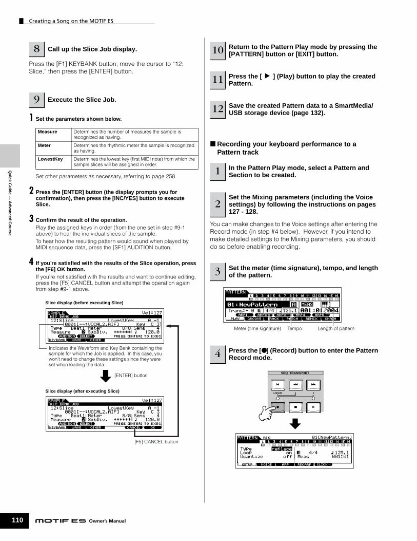
Creating a Song on the MOTIF ES
110
Qu
ick Gu
ide —
Ad
vanced
Co
urse
Press the [F1] KEYBANK button, move the cursor to “12: Slice,” then press the [ENTER] button.
1 Set the parameters shown below.
Set other parameters as necessary, referring to page 258.
2 Press the [ENTER] button (the display prompts you for confirmation), then press the [INC/YES] button to execute Slice.
3 Confirm the result of the operation. Play the assigned keys in order (from the one set in step #9-1 above) to hear the individual slices of the sample.To hear how the resulting pattern would sound when played by MIDI sequence data, press the [SF1] AUDITION button.
4 If you’re satisfied with the results of the Slice operation, press the [F6] OK button.If you’re not satisfied with the results and want to continue editing, press the [F5] CANCEL button and attempt the operation again from step #9-1 above.
8 Call up the Slice Job display.
9 Execute the Slice Job.
Measure Determines the number of measures the sample is recognized as having.
Meter Determines the rhythmic meter the sample is recognized as having.
LowestKey Determines the lowest key (first MIDI note) from which the sample slices will be assigned in order.
Slice display (before executing Slice)
Indicates the Waveform and Key Bank containing the sample for which the Job is applied. In this case, you won’t need to change these settings since they were set when loading the data.
Slice display (after executing Slice)
[F5] CANCEL button
[ENTER] button
Owner’s Manual
■ Recording your keyboard performance to a Pattern track
You can make changes to the Voice settings after entering the Record mode (in step #4 below). However, if you intend to make detailed settings to the Mixing parameters, you should do so before enabling recording.
10 Return to the Pattern Play mode by pressing the [PATTERN] button or [EXIT] button.
11 Press the [F] (Play) button to play the created Pattern.
12 Save the created Pattern data to a SmartMedia/USB storage device (page 132).
1 In the Pattern Play mode, select a Pattern and Section to be created.
2Set the Mixing parameters (including the Voice settings) by following the instructions on pages 127 - 128.
3 Set the meter (time signature), tempo, and length of the pattern.
4 Press the [● ] (Record) button to enter the Pattern Record mode.
Meter (time signature) Tempo Length of pattern
SEQ TRANSPORT
LOCATE 1 2

Qu
ick
Gu
ide
— A
dva
nce
d C
ou
rse
Creating a Song on the MOTIF ES
Set the Type to “overdub” then set the Loop to “on.” These settings let you repeat the pattern recording in a “loop” and record additional note events without deleting already-recorded data. Set other parameters as necessary. See page 243 for details.
Call up the display for setting a Voice by pressing the [F2] VOICE button. You won’t need to make settings in this display if you’ve already completed Voice/Mixing settings in step #2 above.
5Press the [TRACK SELECT] button (the lamp lights), then select the desired track from the number buttons [1] - [16].
6 Set the parameters related to recording in the [F1] SETUP display.
7Set the parameters related to the Voice you wish to use during recording in the [F2] VOICE display.
ELEMENT/PERF. PART/ZONE
87654321
16 MUTE
TRACKSELECT
SOLO
151412 1311109
Recording track
This lets you turn the click sound (metronome) on/off for recording. (Press the [F5] button.)
Bank Number
When a Drum Voice is selected, for example, try recording the rhythm pattern shown below. As shown in the example below, notes that you record will play back from the next repetition (loop), letting you record while hearing previously recorded material.
This operation exits from the Pattern Record mode to the Pattern Play mode.
8 Press the [F] (Play) button to start recording.
9 Press the [■ ] (Stop) button to stop recording.
10 Press the [F] (Play) button to hear your newly recorded phrase.
11 Record different phrases to other tracks by repeating steps #4 - 10.
12Save the created Pattern data to a SmartMedia/USB storage device (page 132) before turning the power off.
SEQ TRANSPORT
LOCATE 1 2
Bass Drum
Snare DrumBass Drum
Snare DrumHi-Hat
Bass Drum
Actual recording starts after one measure.
Loop 1st round
Loop 2nd round
Loop 3rd round
Start recording
111Owner’s Manual

Creating a Song on the MOTIF ES
112
Qu
ick Gu
ide —
Ad
vanced
Co
urse
■ Recording a rhythm pattern created by Arpeggio playback to a Pattern track
The Arpeggio function is a virtually endless source of creative inspiration, putting a huge variety of rhythm patterns, riffs and phrases at your fingertips — patterns that change depending on the notes you play. Once you come with some patterns you like and want to use in a Song, you can record them to a Pattern track.
You can make changes to the Voice settings after entering the Record mode (in step #5 below). However, if you intend to make detailed settings to the Mixing parameters, you should do so before enabling recording.
1 Enter the Mixing Edit mode ([MIXING] →→→→ [EDIT]), select the desired Part (track to be recorded), then press the [F1] VOICE button, followed by the [SF2] MODE button.
2 Set the ArpSwitch (Arpeggio Switch) parameter to “on.”
3 Call up the Arpeggio Type selection display ([COMMON] →→→→ [F3] ARP →→→→ [SF1] TYPE).
4 Select the desired Arpeggio type in the [SF1] TYPE display, then press the [ARPEGGIO ON/OFF] button (the lamp lights).
Try out various Arpeggio types, and also try tweaking various parameters in the [SF1] - [SF4] displays. When you find a rhythm or phrase that you like and want to use, go to step #4.
1 In the Pattern mode, select a Pattern and Section to be created.
2Set the Mixing parameters (including the Voice settings) by following the instructions on pages 127 - 128.
3 Play with the Arpeggio features and find a rhythmic pattern/phrase you like.
REMOTE ARPEGGIO
ON/OFF ON/OFFR-AUDIOG-MIDI
Select an Arpeggio Type and Bank.
Owner’s Manual
For details about how to select a track, see page 58.
Set Type to “replace” and set Loop to “off.”Set other parameters as necessary. See page 243 for details.
Call up the display for setting a Voice by pressing the [F2] VOICE button. You won’t need to make settings in this display if you’ve already completed Voice/Mixing settings in step #2 above.
Call up the display for setting a Voice by pressing the [F3] ARP button. You won’t need to make settings in this display if you’ve already completed Arpeggio settings in the Mixing Edit mode, in step #3 above.
4 Go back to the Pattern Play mode, then set the meter, tempo, and length of the current pattern.
5 Press the [● ] (Record) button to enter the Pattern Record mode.
6 Select the desired track for recording ([1] - [16]).
7 Set the parameters related to recording in the [F1] SETUP display.
8Set the parameters related to the Voice you wish to use during recording in the [F2] VOICE display.
9Set the parameters related to an Arpeggio you wish to use during recording in the [F3] ARP display.
10 Set the RecArp parameter to “on” in the [F4] RECARP display.
When this is set to “on,” the Arpeggio playback data is recorded to a track as MIDI sequence data.

Creating a Song on the MOTIF ES
Qu
ick
Gu
ide
— A
dva
nce
d C
ou
rse
During recording, play the note or notes needed to trigger the Arpeggio you found in step #3.
■ Assigning a pre-programmed Phrase to a Pattern track The Pattern mode also has a versatile Patch function that lets you assign pre-programmed one-track rhythm “Phrases” to each track. Use the special preset Phrases already in internal memory, or create your own User Phrases — by recording, or loading Pattern data from the included CD-ROM (Sound Library for MOTIF ES6/MOTIF ES7/MOTIF ES8). Use the Assigning Phrases function to assemble your original Patterns, with up to 16 tracks.
The instrument provides a total capacity of 256 User Phrases. Keep in mind that these are originally empty and have no data, unless you record or load data to them.
11 Press the [F] (Play) button to start recording.
12 Turn the [ARPEGGIO ON/OFF] indicator off, and press the [F] (Play) button to hear your newly recorded phrase.
13 Save the created Pattern data to a SmartMedia/USB storage device (page 132) before turning the power off.
1 In the Pattern Play mode, select a Pattern and Section to be created.
2 Press the [F4] PATCH button to call up the Patch display.
3 Select the desired track and assign a Phrase to the selected track.
4 Select another track and assign a User Phrase to it.
SEQ TRANSPORT
LOCATE 1 2
Recording stops automatically when Pattern playback reaches the end, since Loop is set to “off.”
Start recording
Actual recording starts after one measure.
Arpeggio playback
ELEMENT/PERF. PART/ZONE
87654321
16 MUTE
TRACKSELECT
SOLO
151412 1311109DEC/NO INC / YES
SEQ TRANSPORT
LOCATE 1 2
Select a track. Select a Preset Phrase.
Play the Pattern to confirm the assigned Phrase.
Indicates the category of the preset Phrases.
Indicates the Phrase number.
ELEMENT/PERF. PART/ZONE
87654321
16 MUTE
TRACKSELECT
SOLO
151412 1311109
DEC/NO INC / YES
SEQ TRANSPORT
LOCATE 1 2
Select a track. Select a User Phrase.
Play the Pattern to confirm the assigned Phrase.
113Owner’s Manual

Qu
ick Gu
ide —
Ad
vanced
Co
urse
Creating a Song on the MOTIF ES
114
The User Phrases that can be assigned with the Patch function are limited to the ones contained in the currently selected Pattern. To copy Phrases from other Patterns for use in the current one, follow the instructions below.
1 In the [F4] PATCH display, press the [SF5] COPY button to call up the Copy Phrase display.
2 First, specify the source Pattern number and Phrase number as well as the destination (current Pattern) Phrase number and track number. Then, press the [ENTER] button to execute the Copy operation.
3 Press the [EXIT] button to return to the [F4] PATCH display, then check the assigned Phrase by pressing the [FFFF] (Play) button to play the Pattern.
Using the Groove function
The Groove function makes it possible to adjust the pitch, timing, length, and velocity of notes in a specified track via a 1-measure 16th-note grid to create interesting, unique “grooves” that would not be possible with precise sequencer-like programming.
n The Groove settings are applied to all measures of the current Pattern. Keep in mind that you cannot apply different Groove settings to each measure.
n The Grid Groove function affects Pattern playback without actually changing the MIDI sequence data (created via the Recording, Sampling, File Loading, and Patch functions). The Groove settings are handled separately from MIDI sequence data. See page 167.
5 Select a different track and copy the User Phrase from the another pattern to the selected Pattern’s track.
6 Save the created Pattern data to a SmartMedia/USB storage device (page 132) before turning the power off.
1 In the Pattern Play mode, select a Pattern and Section for which the Groove is to be applied.
2 Press the [F2] GROOVE button to call up the Groove display.
3 Select the desired track and adjust the Groove parameters.
Pattern 025 usr:
009 08
Source Pattern number, Phrase number
Destination Phrase and track of the current edited Pattern.
When this box is checkmarked, Sample Voices assigned to the source Phrase are copied to the destination Phrase as Sample Voices, and are assigned to the corresponding tracks in the selected Pattern.
pre:005
usr:029
usr:009
ELEMENT/PERF. PART/ZONE
87654321
16 MUTE
TRACKSELECT
SOLO
151412 1311109
SEQ TRANSPORT
LOCATE 1 2
DEC/NO INC / YESEXIT ENTER
EXECUTE
DEC/NO INC / YES
0
VELO OFST
GATE OFST
CLOCK SFT NOTE OFST
Move the cursor... Set the value.
Grid
minus plus
NOTE OFST (Note Offset) Raises or lowers the pitch of the note(s) on the selected grid in semitones.
CLOCK SFT (Clock Shift) Shifts the timing of the note(s) on the selected grid forward or backwardin clock increments.
GATE OFST (Gate time Offset) Lengthens or shortens the note(s) on the selected grid in clock increments.
VELO OFST (Velocity Offset) Increases or decreases the velocity of the note(s) on the selected grid.
n You can edit the Groove parameters in real time during playback.
Select a track.
Set each parameter.
Play the Pattern to check the result of the
Groove settings.
Move the cursor to the desired parameter and grid point and set the offset value.
Owner’s Manual

Qu
ick
Gu
ide
— A
dva
nce
d C
ou
rse
Creating a Song on the MOTIF ES
Using the Groove settings to change the Pattern data
Grid Groove is a playback-only feature that processes the recorded data of a Pattern without actually changing it. In other words, the original data (created via the Recording, Sampling, File Loading and Patch functions) remains intact. If you want to make the Grid Groove settings permanent and change the data, use Normalize Play Effect in the Pattern Jobs ([PATTERN] → [JOB] → [F5] TRACK → 04: Normalize Play Effect). From this display, specify the track to be changed according to the Groove settings, and press the [ENTER] button to execute.
Creating a Section and Pattern Chain
■ Creating a SectionEach Pattern consists of 16 Sections (A~H) which can be used as Pattern variations. Create the desired rhythm pattern variations, or Sections, that you wish to use as accompaniment and backing for your new Song. After you’ve created the Sections, you can string these Sections together in any order desired to assemble the backing part of the Song, over which you can record a melody line and any other parts, in the Song Record mode.
n Pattern Mixing, Groove, and Phrase Voice (Track Voice) on/off (page 167) cannot be set independently for each Section, but apply to all Sections.
The same User Phrases can be assigned to different Sections within a pattern. Keep in mind, however, that the Section data will automatically be changed if another Section sharing the same User Phrase is changed. For example, if you’ve assigned a certain User Phrase to both Section A and Section D, and you change that User Phrase for Section A, the same Phrase will be changed for Section D as well.
■ Creating a Pattern Chain by changing a Section The Pattern (“patt”) track lets you record Section changes at
4 Save the created Pattern data to a SmartMedia/USB storage device (page 132) before turning the power off.
TIP
........Section A Section B Section F Section H
Convert
Song
Pattern Chain.....Enter the desired Sections for the Song
CAUTION
while playing a PatternSwitching of sections, track muting, scene/mute changes, and tempo changes can all be recorded in real time as the Pattern Chain.
In the Pattern Chain Record Setup display, you can set the Recording track and tempo. Three Pattern Chain track types are available. The Tempo track lets you record tempo changes for the Chain, and the Scene track lets you record track on/off changes.
1 In the Pattern Play mode, select a Pattern for which data has already been created.
2 Press the [F6] CHAIN button to call up the Pattern Chain Play display.
3 Press the [● ] (REC) button to enter the Pattern Chain Record mode, then set the basic parameters.
the desired measure points in the Song.
SEQ TRANSPORT
LOCATE 1 2
Pattern Chain Play display
Pattern Chain Record Setup display
Set the recording track to “patt” and enter the Sections to the desired measures.
Tempo
Owne
115r’s Manual
Creating a Song on the MOTIF ES
116
Qu
ick Gu
ide —
Ad
vanced
Co
urse
Change the Section at the desired points, as the Pattern plays.
Operation returns to the Pattern Chain display.
You can also record the Tempo track and Scene track as desired. When the recording track is set to “tempo,” move the cursor to tempo value (during recording in step #4 above) and use the data dial and the [INC/YES]/[DEC/NO] buttons to change the tempo while the Chain is playing. When the recording track is set to “scene,” press the [MUTE] button (the lamp lights) and use the number buttons [1] - [16] to turn each track on/off as desired during recording.
4 Press the [F] (Play) button to start recording and play the Pattern.
5 Press the [■ ] (Stop) button to stop recording.
6 Press the [F] (Play) button to hear the recorded Pattern Chain.
7Save the created Pattern data to a SmartMedia/USB storage device (page 132) before turning the power off.
SEQ TRANSPORT
LOCATE 1 2
A. PIANO KEYBOARD ORGAN
PRE 5 PRE 6 USER 1
GUITAR/PLUCKED
SYN LEAD
A B C D E F G H SECTION
CATEGORYSEARCH
SYN PAD/CHOIR
SYN COMP CHROMATICPERCUSSION
DRUM/PERCUSSION
SE MUSICAL FX COMBI
USER 2
STRINGS
PLG 1
BRASS
PLG 2
REED/PIPE
PLG 3
BASS
GM
Section I-P
Section A-H
Owner’s Manual
■ Editing a Pattern ChainThe Pattern Chain Edit mode makes it possible to edit the order of the Sections in a chain as well as inserting tempo, and scene/mute event data.
1 In the Pattern Play mode, select a Pattern for which data has already been created.
2 Press the [F6] CHAIN button to call up the Pattern Chain Play display.
3Press the [EDIT] button to enter the Pattern Chain Edit mode, then edit each track of the Pattern Chain.
4Press the [EXIT] button to return to the Pattern Chain Play display, then press the [F] (Play) button to hear the edited Pattern Chain.
5Save the created Pattern Chain as Pattern data to a SmartMedia/USB storage device (page 132) before turning the power off.
EDIT
Press the [F6] button to clear the event at the cursor location.
Press the [F5] button to insert the event to the cusor location.
Press the [F6] button to delete the event at the cursor location.
Pattern Track Edit
Scene Track Edit
Tempo Track Edit
[F4] button
[F4] button
[F4] buttonEnter the desired section (A - P) or the End mark by using the [INC/YES] and [DEC/NO] buttons.

Qu
ick
Gu
ide
— A
dva
nce
d C
ou
rse
Creating a Song on the MOTIF ES
■ Converting a Pattern Chain to Song data
1In the Pattern Play mode, select a Pattern for which Pattern Chain data has already been created.
2 Press the [F6] CHAIN button to call up the Pattern Chain Play display.
3 Press the [EDIT] button to enter the Pattern Chain Edit mode.
4Press the [F3] SONG button to call up the “Convert to Song” display, then specify the destination Song.
When this box is checkmarked, program change messages in the MIDI sequence data are not copied.
Destination Song number and the top measure number
The Pattern Chain data is converted to Song data and copied to the top measure of the destination Song.
This operation overwrites any data already existing at the destination Song.
The created Song data resides temporarily in DRAM (page 187). Because data contained in DRAM is lost when the power is turned off, you should always store any data residing in DRAM to a SmartMedia/USB storage device before turning off the power.
5 Press the [ENTER] button to execute the Convert operation.
6Save the Song data to a SmartMedia/USB storage device (page 132) before turning the power off.
CAUTION
CAUTION
Creating a Song
The following chart illustrates the basic procedure for creating a Song, using the various methods and functions described in this tutorial. Now, that you’ve assembled the backing tracks for your Song (by converting the Phrases or Pattern Chain to Song data, you can now record melody parts on top of them.
The created Song data resides temporarily in DRAM (page 187). Because data contained in DRAM is lost when the power is turned off, you should always store any data residing in DRAM to a SmartMedia/USB storage device before turning off the power.
Song track 1
Song track 2
Song track 3
Song track 4
Song track 5
Song track 6
Song track 7
Song track 8
Song track 9
Song track 10
Song track 11
Song track 12
Song track 13
Song track 14
Song track 15
Song track 16
Record your keyboard performance to each track one by one in the Song Record mode, called up via [SONG] → [● ] (REC).
Record audio data in the Sampling mode.
Copy the Phrase to the Song in the [SONG] → [F5] PHRASE display.
Convert the Pattern Chain to Song data ([PATTERN] → [F6] CHAIN → [EDIT] → [F3] SONG).
Page 118
Page 122
Page 222
Page 117
Keyboard Performance
Audio data
Phrase
Pattern Chain
Song track
CAUTION
117Owner’s Manual

Creating a Song on the MOTIF ES
118
Qu
ick Gu
ide —
Ad
vanced
Co
urse
Recording with the keyboard to a Song track (in the Song Record mode)
■ Recording your keyboard performance to an empty track (Replace)
Use the Replace recording method to record your keyboard performance to an empty track or overwriting an already recorded track with new data.
You can make changes to the Voice settings after entering the Record mode (in step #3 below). However, if you intend to make detailed settings to the Mixing parameters, you should do so before enabling recording.
Song data is made up of three different types — Scene, Tempo and Pattern — each of which have their own separate tracks. The Scene track contains Song Scene (page 123) changes and the Tempo track contains playback tempo changes. The Song tracks (1 - 16) contain the actual note data. Since you’ll be recording a melody with the keyboard, select one of the number tracks, using the [1] - [16] buttons.
n When the RecTrack is set to “multi,” you can simultaneously record multiple channels of MIDI data (up to 16 channels) to all 16 tracks. For details, see page 143.
1 In the Song Play mode, select a Song to be created.
2 Set the Mixing parameters (including the Voice settings) by following the instructions on pages 103 - 104.
3 Press the [● ] (Record) button to enter the Song Record mode.
4Press the [TRACK SELECT] button (the lamp lights), then select the desired track from the number buttons [1] - [16].
SEQ TRANSPORT
LOCATE 1 2
ELEMENT/PERF. PART/ZONE
87654321
16 MUTE
TRACKSELECT
SOLO
151412 1311109
temposcene 1-16
Owner’s Manual
Set the Type parameter to “replace.” Set other parameters as necessary. See page 222 for details.
Call up the display for setting a Voice by pressing the [F2] VOICE button. You won’t need to make settings in this display if you’ve already completed Voice/Mixing settings in step #2 above.
n Non-note settings (such as Voice, volume and pan) that are made at the beginning of a Song are not recorded as MIDI sequence data but rather as Mixing setup data. However, when these non-note settings are recorded in the middle of a Song, they are recorded as part of the MIDI sequence data.
Listen to the playback of the already recorded tracks and play (record) the keyboard along with them.
This operation exits from the Song Record mode to the Song Play mode.
5 Set the parameters related to recording in the [F1] SETUP display.
6 Set the parameters related to the Voice you wish to use during recording in the [F2] VOICE display.
7 Press the [F] (Play) button to start recording.
8 Press the [■ ] (Stop) button to stop recording.
9 Press the [F] (Play) button to hear your newly recorded song.
10 Record additional melody parts to the other tracks as needed by repeating steps #3 - 9 above.
11Save the created Song data to a SmartMedia/USB storage device (page 132) before turning the power off.
This lets you turn the click sound (metronome) on/off for recording. (Press the [F5] button.)
Bank Number
SEQ TRANSPORT
LOCATE 1 2Start recording
Actual recording starts after one measure.

Qu
ick
Gu
ide
— A
dva
nce
d C
ou
rse
Creating a Song on the MOTIF ES
■ Re-recording a specific part of a Song (Punch In/Out)Use the Punch In/Out recording method to record over only a specific portion of the track. In the example instructions below, you’ll see how to re-record measures three through five of an already recorded Song.
Set the Type parameter to “punch” and specify the area to be re-recorded.Set other parameters as necessary. See page 222 for details.
1 In the Song Play mode, select a Song to be created.
2 Press the [● ] (Record) button to enter the Song Record mode.
3Press the [TRACK SELECT] button (the lamp lights), then select the desired track from the number buttons [1] - [16].
4 Set the parameters related to recording in the [F1] SETUP display.
5 Press the [F] (Play) button to start recording.
6Press the [■ ] (Stop) button to stop recording after the Song playback reaches the Punch Out point.
7 Press the [F] (Play) button to hear the part you’ve just re-recorded.
Punch In (Recording start measure : beat)Playback of the recording track is turned off from this point, and your keyboard performance will be recorded to the track.
Location setting(page 58)
Punch Out (Recording end measure : beat)Recording ends at this point and normal playback of the recording track starts.
Press the [SF1] COPY LOC to assign the measure numbers registered to the Locations (Loc1 and Loc2) to the Punch In and Punch Out points.
SEQ TRANSPORT
LOCATE 1 2
When Song playback reaches the Punch In point, play the keyboard.
Playback start
n Punch In/Out recording is available only in the Song Record mode. This is not available in the Pattern Record mode.
■ Recording additional notes to an already-recorded track (Overdub)
Use the Overdub recording method when you want to add more data to a track that already contains data. This is useful not only for recording more notes to a track; it’s also convenient for adding non-note, sound-shaping data, such as that of the Knobs and Ribbon Controller.
Set the Type parameter to “overdub.” Set other parameters as necessary. See page 222 for details.
Playback starts, and the notes (or controller data) you play are added to the existing data.
8Save the created Song data to a SmartMedia/USB storage device (page 132) before turning the power off.
1 In the Song Play mode, select a song to be created.
2 Press the [● ] (Record) button to enter the Song Record mode.
3Press the [TRACK SELECT] button (the lamp lights), then select the desired track from the number buttons [1] - [16].
4 Set the parameters related to recording in the [F1] SETUP display.
5 Press the [F] (Play) button to start recording.
6Press the [■ ] (Stop) button to stop recording after the Song playback reaches the Punch Out point.
7 Press the [F] (Play) button to hear the part you’ve just re-recorded.
8Save the created Song data to a SmartMedia/USB storage device (page 132) before turning the power off.
119Owner’s Manual

Creating a Song on the MOTIF ES
120
Qu
ick Gu
ide —
Ad
vanced
Co
urse
Rehearsing parts before recording
The MOTIF ES has a convenient Rehearsal mode in recording, that lets you easily and temporarily disable recording in order to practice a part or try out various ideas (while listening to the other tracks) without actually recording.To temporarily disengage the record mode and enter the “Rehearsal” mode, simply press the [● ] (Record) button during realtime recording – the [● ] (Record) indicator will flash and playback will continue uninterrupted but no data will be recorded. To return to the record mode press the [● ] (Record) button again – the [● ] (Record) indicator will light continuously. You can repeat this process as often as you wish, pressing the [■ ] (Stop) button to cancel the Rehearsal mode. The Record button lamp indicates the Recording/Rehearsal status: continuously lit indicates Recording, and flashing indicates Rehearsal.
Insert a Tempo change event to the middle of the Song
You can use the following three methods to change the tempo in the middle of the already-recorded song.
● Using the Tempo trackStart recording after setting the Type parameter to “replace,” setting RecTrack to “tempo,” and moving the cursor to the tempo value in step #4 on page 118. During recording, change the tempo value while listening to Song playback.
● Song EditIn the Song Play mode, press the [EDIT] button to enter the Song Edit mode. Select the Tempo track (TMP) by pressing the [F4] TR SEL button once or twice, then change the existing tempo value or insert a new tempo value by using the [F5] INSERT button. For details about Song Edit, see page 124.
● Step RecordingIn step #4 on page 118, set the Type parameter to “step” and RecTrack to “tempo” then press the [F] (Play) button to start Step recording. After moving the cursor to “Value,” move the song pointer by using the [H] (Forward) button and change the tempo value at the desired point. For details about Step Recording, see page 238.
TIP
SEQ TRANSPORT
LOCATE 1 2
SEQ TRANSPORT
LOCATE 1 2
Recording Rehearsal mode (playback continues)
TIP
Owner’s Manual
Song Recording using a PerformanceIf you have a favorite Performance or one that would fit the Song to be recorded, you can copy certain settings of up to four Parts of the Performance to the Song Mixing settings currently being edited.
1 Enter the Song Mixing Job mode ([SONG] →→→→ [MIXING] →→→→ [JOB]).
2 Press the [F5] PF COPY button to call up the Performance Copy display.
3 Set the parameters as necessary in the [F5] PF COPY display, then press the [ENTER] button to execute the Copy operation.
4 Press the [SONG] button to return to the Song Play mode, then select Track 1 and play the keyboard. Check whether the sound you hear is the same as that of the source Performance or not.
5 Record your keyboard performance to Track 1.
6 Store the Song Mixing in the [SONG] →→→→ [MIXING] →→→→ [STORE] display. The settings copied from the Performance should be stored as Song Mixing data.
7 Save the created Song data to a SmartMedia/USB storage device (page 132) before turning the power off.
n The explanations above also apply to the Pattern mode.
Step RecordingThe explanations in this Quick Guide have concentrated on Realtime Recording. However, the Step Recording method is also available, letting you record a Song by entering notes and events individually — much like writing them down on paper. This is especially useful for recording passages that would be difficult or impossible to play. The Step Recording can be executed by setting the Type to “step” in the [F1] SETUP display in the Song Record mode. For details on using Step Recording, see page 238.
n Step Recording can be used both in the Song Record mode and the Pattern Record mode.
TIP
1.2.3
The destination Mixing Parts appear automatically. The displayed Part numbers differ depending on the source Performance. If the source Performance contains four Parts, “1, 2, 3, 4” appears here.
Select a source Performance. Checkmark the boxes of the desired parameters.

Creating a Song on the MOTIF ES
Song Recording using Plug-in Voices
This section shows you how to use the Voices of an optional Single Part Plug-in Board (such as PLG150-AN, PLG150-PF and PLG150-DX) in recording a Song.
1 ~ 4 When you play the keyboard, you should be able to hear
TIP
Qu
ick
Gu
ide
— A
dva
nce
d C
ou
rse
Install a Single Part Plug-in Board to the instrument, then follow steps #1 - 4 on page 75 to set the necessary parameters. In step #4, set PORT.NO (port number) to “2” or “3.” Keep in mind that if you’ve also installed a PLG100-XG Multi-Part Plug-in Board, the boards should be set to different numbers.
5 Enter the Song Play mode and call up the MIDI output setting display ([SONG] →→→→ [F3] TRACK →→→→ [SF1] CHANNEL).
6 Select the track for recording, making sure that the track number is the same as that of the slot to which the Plug-in Board is installed, and set the port number.The track number must match the slot number, and the port number must be the same as set in step #4 above.
7 Select a Voice of the installed Plug-in Board. Enter the Mixing Edit mode ([MIXING] → [EDIT] → Part selection). Press the [F6] button once or twice to call up the display for the Plug-in Board parts (PLG parts) as shown below (page 164). Next, press the [TRACK SELECT] button (the lamp lights), and select the PLG Part of Slot 1 by pressing the [1] button. Finally, press the [F1] VOICE button, followed by the [SF1] VOICE button, then select the desired Voice on the Plug-in Board.
When a Single Part Plug-in Board has been installed to slot 1, move the cursor here then set the port number.
When a Single Part Plug-in Board has been installed to slot 1, move the cursor here then set the port number.
Voice Bank
Voice Number
the selected Voice of the Plug-in Board. If the Voice of the Plug-in Board does not sound as expected, check the following points.
● Make sure that the OUT CH of the track matches the Receive Channel of the corresponding Part of the tone generator.Check the ReceiveCh (MIDI Receive Channel) in the display called up by pressing the [SF2] MODE in the above display, then check the OUT CH (MIDI Output Channel) of track 1 in the display shown in step #6. These two channels should be same.
● Make sure that the destination tone generator is set to internal, not external.Check the settings in the display called up via the [F1] PLAY → [SF2] OUT CH button. The INT SW of the corresponding track (1 in this case) should be set to “on.”
8 Record your keyboard performance using the Plug-in Voice to track 1.
9 Store the Song Mixing settings in the [SONG] →→→→ [MIXING] →→→→ [STORE] display (page 131). The settings related to the Plug-in Board voice should be stored as Song Mixing data.
10 Save the created Song data to a SmartMedia/USB storage device (page 132) before turning the power off.
n The explanations above apply also to the Pattern modes.
121Owner’s Manual

Creating a Song on the MOTIF ES
122
Qu
ick Gu
ide —
Ad
vanced
Co
urse
Using the Groove function
Just as in the Pattern Play mode, the Groove function is available also in the Song Play mode. For details, refer to the explanation of Groove in the Pattern Play mode (page 114).
The created Song data resides temporarily in DRAM (page 187). Because data contained in DRAM is lost when the power is turned off, you should always store any data residing in DRAM to a SmartMedia/USB storage device before turning off the power.
Sampling a one-shot sound to a Song track
The MOTIF ES conveniently lets you sample audio material, even while a Song is playing. This allows you to quickly and easily “fly in” samples to your Song as you need them — for example, capturing short sound effects from a CD, or recording background vocal phrases with a microphone. Sounds like these can be added to the Song as desired, and can even be aligned in time as needed after recording in the Song Edit mode.
In order to use the Sampling function, DIMM modules must be installed to the instrument. For details on installing DIMMs, see page 289.
Follow steps #1 - 8 on page 73, substituting the instructions below for steps #4 and 8.In step #4, press the [SONG] button to enter the Song Play mode then select a song to be created. In step #8, set the related parameters from the AUDIO IN display ([SONG] → [MIXING] → [EDIT] → [COMMON] → [F5] AUDIO IN).
1 In the Song Play mode, select a Song for which the Groove settings are to be applied.
2 Press the [F2] GROOVE button to call up the Groove setting display.
3 Select a track, then adjust the Groove settings.
4Save the created Song data to a SmartMedia/USB storage device (page 132) before turning the power off.
1 Connect an audio device (CD player, etc.) to the instrument.
2 Press the [INTEGRATED SAMPLING] button in the Song mode to enter the Sampling mode.
CAUTION
Owner’s Manual
Type: sample+noteSource: A/DNext: offMono/Stereo: stereoFrequency: 44.1k
For details about each parameter, see page 253.
Set the TrggrMode (Trigger Mode) to “meas” then specify the Punch In measure (at which the Sampling starts automatically) and the Punch Out measure (at which Sampling stops automatically).
3Press the [F2] SOURCE button to call up the display for setting the Sampling Source, then set the parameters as shown below.
4Press the [F1] DEST button to call up the display for setting the Sampling Destination, set the parameters as described below.
Track This parameter determines the Song track to which the Sample Voice is assigned.
Keybank This parameter determines the note to which the sample is assigned.
5Press the [F6] REC button to call up the Sampling Record display (Sampling Standby status), then set the parameters as required.
Punch Out measureMeasure number at which Sampling stops automatically
Punch In measureMeasure number at which Sampling starts automatically
Indicates Sampling Standby status.

Qu
ick
Gu
ide
— A
dva
nce
d C
ou
rse
Creating a Song on the MOTIF ES
Doing this puts sample recording on standby, waiting for song/pattern playback to reach the specified Punch-in measure.
Audio is recorded to the instrument.
6 Press the [F6] REC button again enable Punch In Waiting.
7 Press the [F] (Play) button to start Song playback.
8Start the audio equipment when the Song reaches the Punch In point (when sampling actually starts).
F6
Indicates that sample recording is waiting for song/pattern playback to reach the specified Punch-in measure.
Song
Operation then returns to the [F1] DEST or [F2] SOURCE display. Press the note set in KeyBank in step #3 to check the recorded sample.
Listen back to the Song (the sample automatically sounds along with playback) and check that the timing is correct. If you’re not satisfied with the timing, you can adjust it as needed in the Song Edit mode. For details about Song Edit, see page 124.
9Stop the audio equipment when the Song reaches the Punch Out point (when sampling stops).
10 Press the [SONG] button or [EXIT] button to return to the Song Play mode.
11 Press the [F] (Play) button to play the Song.
12Save the Song data to a SmartMedia/USB storage device in the File mode (page 132) before turning the power off.
Registering a Song Scene and Arpeggio type simultaneously to the [SF1] - [SF5] buttons
Song Scenes and Arpeggio types can both be registered to the [SF1] - [SF5] buttons (when the ARP1 - ARP5 menu items are shown at the bottom of the display). These settings are stored as Song data. Song Scene is a powerful function that allows you to store five different “snapshots” of important Song related parameters – including transpose, tempo, track mute status, and the basic sound/mixing controls (all parameter settings controllable from the Knobs with the [PAN/SEND] or [TONE] lamp turned on, and the Control Sliders). The Arpeggio function and Arpeggio types are discussed in detail in the Voice mode, on page 66. You can call up both the Song Scene and Arpeggio type simultaneously by simply pressing one of the [SF1] - [SF5] buttons (when ARP1 - ARP5 are shown at the bottom of the display in the Song mode).
SCENESF1 SF2 SF3 SF4 SF5
SCENE STORESET LOCATE
STORE SCENESF1 SF2 SF3 SF4 SF5
ARPEGGIO
ON/OFF
● Registering a Song Scene and Arpeggio type simultaneously to the [SF1] - [SF5] buttons
● Recalling a Song Scene and Arpeggio type simultaneously from the [SF1] - [SF5] buttons
In the Song mode, you can register the Song Scene and Arpeggio type simultaneously to the [SF1] - [SF5] buttons only when the ARP1 - ARP5 menus appear at the bottom in the display.
Simultaneously hold the [STORE] button and press one of the [SF1] - [SF5] buttons.
123Owner’s Manual

Creating a Song on the MOTIF ES
124
Qu
ick Gu
ide —
Ad
vanced
Co
urse
■ Recalling a Song Scene and Arpeggio type during recordingARP1 - ARP5 menus appear also in the [F3] ARP display in the Song Record mode as well as the [F1] PLAY display in the Song Play mode. These indicate that you can change the Song Scene and Arpeggio type simultaneously during Song recording from the [F3] ARP display.
■ Recording Song Scene changes to a songEach Song contains a Scene track to which you can record Scene changes. When the RecTrack is set to “scene” in step #4 described on page 118, you can record Scene changes from any display (even from those in which ARP1 - ARP5 are not shown) by pressing the [SF1] - [SF5] buttons during recording.
n The explanations on Arpeggio here also apply to the Pattern mode.
n As in the Voice mode and Performance mode, Arpeggio types can only be registered to the [SF1] - [SF5] buttons when the [ARPEGGIO ON/OFF] button is turned off.
n For details on how to select an Arpeggio type in the Song mode/Pattern mode, see page 105.
Editing the recorded song
The Song Edit mode and Song Job mode can be used to edit or change the data of the already recorded song. The Song Edit mode lets you change the recorded data and insert new data if needed. This includes note data as well as non-note data, such as program (Voice) changes and MIDI control change messages. The Song Job mode on the other hand provides a comprehensive variety of tools you can use to transform the recorded data — such as cleaning up the timing (Quantize), transposing, changing the velocity of notes, modifying the length of notes, and other useful operations for altering the sound. It also includes a variety of convenient operations, such as copying or erasing data. Most of these operations can be performed on either an entire track or a selected range of measures in the track.
n The explanations here also apply to the Pattern mode.
■ Editing the recorded Song data by MIDI event (in the Song Edit mode)
1 Press the [SONG] button to enter the Song Play mode, then select a Song to be edited.
2 Enter the Song Edit mode by pressing the [EDIT] button (the lamp lights), then press the [F1] CHANGE button to call up the MIDI event list display.
EDIT
007:1-007
Song position MIDI events
Clock (480 clocks per quarter-note)Beat
Measure number
Owner’s Manual

Qu
ick
Gu
ide
— A
dva
nce
d C
ou
rse
Creating a Song on the MOTIF ES
Select one of the three available track types by pressing the [F4] TR SEL (Track Select) button. Each press of the button alternates among the track types. To select one of the Pattern tracks (1 - 16), make sure the 1-16 track edit display is selected (see below), then turn the [TRACK SELECT] button on and press any of the [1] - [16] buttons.
● Editing/Deleting Existing EventsTo edit data in the Event List, use the up/down cursor buttons to highlight the specific event you want to edit, and use the left/right cursor buttons to highlight the data type or parameter to be edited. Then, change the value as needed by using the [INC/YES] and [DEC/NO] buttons or the data dial.The entire line of the edited event will flash on the display. Press the [ENTER] button to actually enter the edited data (the entire line of the edited event will stop flashing). To abort an edit simply highlight to a new event location without pressing the [ENTER] button. Press the [F6] button to delete the event at the current location.
3 Select a track to be edited.
4 Edit the MIDI events of the Song.
ELEMENT/PERF. PART/ZONE
87654321
16
MUTE
TRACKSELECT
SOLO
151412 1311109
Select a track to be edited from 1 - 16.
1 - 16 track edit display
Scene track edit display
Tempo track edit display
[F4] button
[F4] button
[F4] button
● Inserting New EventsTo insert an event, use the up/down cursor buttons to highlight an event at the desired point in the track measure, beat, clock) – this is the location to which the new event will be inserted. Then, follow the steps below.
In the Event List display, you can edit various types of events such as Voice, volume, and pan as well as note events. This means that you could, for example, enter Voice changes to the middle of a track, even if the track was recorded using only one Voice.
n For details about the MIDI events handled in the Event List display, see page 225.
n If you find the display too cluttered, you can filter out certain event types with the View Filter. Simply press the [F2] VIEW FLT button and select the event types you want to be displayed. For details, see page 225.
When changing the value, the entire line will flash on the display indicating this is being edited and not fixed yet.
This value has been fixed as data.
Press the [F6] button to delete the event at the current location.
[ENTER] button
ENTER
EXECUTE
Press the [F1] button or [EXIT] button to abort and return to the main Event List display.
Press the [F6] SET button to actually insert the event shown in the display and remain in display. If you wish to insert the event type currently shown in the display several times, use [F6] SET and press the [F1] or [EXIT] button to return to the main Event List display.
Press the [ENTER] button to actually insert the event and return to the main Event List display.
[F5] button
[F1] button or [EXIT] button
125Owner’s Manual

Creating a Song on the MOTIF ES
126
Qu
ick Gu
ide —
Ad
vanced
Co
urse
Since the Song can be played back from within the Song Edit mode, you can instantly hear and check the changes you’ve made while editing. If you want to hear just the track being edited, use the Solo function (page 58).
■ Transforming the recorded data and other operations — Song Job mode
The Song Job mode has a wide variety of operations for changing and working with Song data. Virtually all of the Jobs share the same procedure, so we’ll explain only one of them here — Quantize, which lets you clean up the timing of a previously recorded track.In the following example, this musical passage has been written with exact quarter-note and eighth-note values.
Even though you think you may have recorded the passage accurately, your actual performance may be slightly ahead of or behind the beat (or both!). Quantize allows you to align all the notes in a track so that the timing is absolutely accurate to the specified note value.
As shown below, the Jobs are divided into six main groups, each of which is selected using the [F1] - [F6] buttons.
5 Press the [F] (Play) button to hear your edited data.
6 Edit other tracks as required by repeating steps #3 through #5 as desired.
7 After editing, press the [SONG] button to return to the Song Play mode.
8Save the edited Song data to a SmartMedia/USB storage device (page 132) before turning the power off.
1Press the [SONG] button to enter the Song Play mode, then select a Song for which the Job is to be applied.
2 Press the [JOB] button to enter the Song Job mode.
[F1] [F2] [F3] [F4] [F5] [F6]
Indicates the Job List. Because all the Jobs cannot be displayed simultaneously, you will need to use the cursor buttons to scroll the display in order to find the desired Job.
Owner’s Manual
After specifying the track and range over which the Job is to be applied, set Quantize to “ ” (8th note) according to the notation example above. Set the Strength to “100%,” SwingRate to “050%,” and GateTime to “100%.” Regarding these parameters, see page 227.
n Set the Quantize value to correspond to the smallest value notes in the track you are working with. For example, if the data was recorded with both quarter notes and eighth notes, use eighth note for the quantize value.
After the Job has been completed, a “Completed” message appears and operation returns to the original display.
An “Executing...” message is shown when it takes a short amount of time to execute the Job. Never attempt to turn off the power while the Job is being executed. Turning the power off in this state results in loss of all user data.
If you are satisfied with the result of the Job, go to step #7. If not, execute the UNDO Job in the [F1] UNDO display in the Song Job mode to restore the data to its previous state, then try out the Job (from step #4) again. For details about Undo, see next page.
In addition to Quantize, you’ll find a variety of other useful and powerful Jobs in the Song Job mode (page 226) and Pattern Job mode (page 244).
[F1] UNDO Undo (Canceling the executed Job)/Redo (Restoring the executed Job) functions
[F2] NOTE Note Data Job
[F3] EVENT Event Job
[F4] MEAS Measure Job
[F5] TRACK Track Job
[F6] SONG Song Job
3Press the [F2] NOTE button, move the cursor to “01: Quantize” then press the [ENTER] button to call up the Quantize Job display.
4 Set the relevant Job parameters.
5 Press the [ENTER] button to execute the Job.
6Press the [SONG] button to return to the Song Play mode, then press the [F] button to hear the song over which the Job is applied.
7Save the Song data to a SmartMedia/USB storage device in the File mode (page 132) before turning the power off.
Track over which the Job is applied Range over which the Job is applied
CAUTION

Creating a Song on the MOTIF ES
Qu
ick
Gu
ide
— A
dva
nce
d C
ou
rse
Using the Undo/Redo functionsIf you’re not satisfied with the results of a just-executed Job, or you want to hear the difference of the sound before and after using a Job, you can use the convenient Undo and Redo functions. After changing the data with a particular Job, repeat steps #1 -4 as desired.
1 Press the [SONG] button to return to the Song Play mode, then press the [F] button to hear the Song as it was changed by the Job.This lets you check the results of the Job.
2 After stopping the song, press the [JOB] button followed by the [F1] UNDO button to call up the Undo display. Press the [ENTER] button to execute Undo. The Song data is restored to its previous state.
3 Press the [SONG] button to return to the Song Play mode, then press the [FFFF] (Play) button to play the song. This lets you check the sound before actually making changes to it with the Job.
4 After stopping the song, press the [JOB] button followed by the [F1] UNDO button to call up the Undo display. Press the [ENTER] button to execute the Redo. This lets you “redo” the Job, restoring the Song to the changes you made before using Undo in step #2 above.
n Undo/Redo is applied to the most recent operation (Job, Edit, Record, etc.).
n The Undo/Redo Job is available also in the Pattern Job mode.
Editing Mixing parameters to complete a Song (in the Mixing mode/Mixing Edit mode)
In this final step (other than saving your precious work, which we’ll cover next), you can mix down your tracks with the Song Mixing function – adjusting the volume balance and pan setting of all the parts and tweaking the effect levels.
n The explanations here also apply to the Pattern mode.
Select the menu you wish to edit by pressing the [F1] - [F4] buttons, then edit the parameters in each display.
You can use the Song Mixing mode for Sample Mixing as well. For information on the available parameters, see page 233. If you wish to edit more detailed Mixing parameters, enter the Song Mixing Edit mode.
1 Press the [SONG] button to enter the Song Play mode, then select a Song for which Mixing edits have been made.
2 Enter the Song Mixing mode by pressing the [MIXING] button (the lamp lights).
TIP
Indicates the operation to be affected by Undo. Changes to “Redo.”
[ENTER] button
Indicates the operation to be affected by Redo. Changes to “Undo.”
[ENTER] button
If you alter any parameters, the [E] indicator will appear in the top left of the display. Press the [F6] button to switch between the display for Parts 01-16 (for the internal tone generator), 17-32 (for the Multi-Part Plug-in Board PLG100-XG), and PLG1-3 (for the Single Part Plug-in Board).
Press the [F5] VCE ED button to enter the Mixing Voice Edit mode (page 105).
127Owner’s Manual

Qu
ick Gu
ide —
Ad
vanced
Co
urse
Creating a Song on the MOTIF ES
128
Use Part Edit to edit the parameters for each Part. Use Common Edit to edit the parameters for all of the Parts.
For details on the available parameters, see page 234.
After pressing the [EXIT] button to return to the Song Mixing mode, press the [STORE] button to enter the Song Mixing Store mode, then press the [ENTER] button to execute the Store operation (page 131).
3 Press the [EDIT] button to enter the Song Mixing Edit mode.
4 Call up the Common Edit display or Part Edit display.
5 Select the menu you wish to edit by pressing the [F1] - [F5] buttons and [SF1] - [SF5] buttons, then edit the parameters in each display.
6 Repeat steps #4 - 5 as desired.
7 Store the edited Song Mixing settings to internal User memory (DRAM).
8 Before turning the power off, save the stored Song Mixing settings to a SmartMedia/USB storage device as Song data in the File mode (page 132).
EDIT
COMPARE SCENE STORESET LOCATE
JOB STORE
COMMON ELEMENT/PERF. PART/ZONE
FAVORITES
DRUM KITS
A. PIANO KEYBOARD GUITAR/PLUCKED
PRE 5 PRE 6 USER 1
GUITAR
SYN LEAD
A B C D
321
11109
SYN PAD/CHOIR
SYN COMP CHROMATICPERCUSSION
USER 2
8
16
......
......
.....
.....
F6
Calling up the Common Edit displayPress the [COMMON] button to call up the Common Edit display. In the Edit mode, the [DRUM KITS] button functions as the [COMMON] button.
While in the Song Mixing Edit mode, you can switch between the Common Edit display and the Element Edit display as shown below.
Indicates a Common Edit display.
Calling up the Part Edit displayPress the desired Part number from the PART [1] - [16] buttons to call up the Part Edit display.
Indicates the display for editing Part 1.
Common Edit
Part1 Edit
To switch between the Part 1 - 16 display, Part 17 - 32, and Part PLG1 - 3 display, press the [F6] button.
n Common Edit operations cannot be performed on the Multi-part Plug-in parts 17 - 32. The Mixing settings for the Muti-Part Plug-in Part (17~32) apply not to one individual song but to all 64 songs.
Internal Tone Generator
Multi-Part Plug-in Board PLG100-XG
Single Part Plug-in Board
n You can mute or solo a Part just as is done with tracks in the Song Play mode or Pattern Play mode. Part2 Edit
Part3 Edit
Part4 Edit
Part 16 Edit
Part 17 Edit
Part 32 Edit
Plug-in part 1 (PLG1) Edit
Plug-in part 2 (PLG2) Edit
Plug-in part 3 (PLG3) Edit
Owner’s Manual

Creating a Song on the MOTIF ES
Qu
ick
Gu
ide
— A
dva
nce
d C
ou
rse
Editing a Mixing by using the Knobs (in the Song mode/Pattern mode)
The four knobs at the top left of the instrument can be used to tweak the Song/Pattern Mixing settings as they play (in the Song Play/Pattern Play mode). What’s mode, you can use them to edit the Mixing settings, in the Song Mixing Edit/Pattern Mixing Edit modes.For details on the parameters edited by the knobs, refer to the descriptions in the Performance mode (page 90).
● When the [PAN/SEND] indicator is turned on:
● When the [TONE] indicator is turned on:
● When the [ARP FX] indicator is turned on:
● When the [EQ] indicator is turned on:
● When both the [PAN/SEND] and [TONE] indicators are turned on (by pressing them simultaneously):
n In addition to the above functions, Master Effect related parameters ([SONG] or [PATTERN] → Song/Pattern selection → [MIXING] → [EDIT] → [COMMON] → [F2] MEQ/MEF → [SF2] MEF) can be assigned to these four knobs, and the knobs can be used for these assignments by pressing the [ARP FX] and [EQ] buttons simultaneously to turn them on. The particular parameters assigned to the four knobs can be set in the [UTILITY] → [F4] CTL ASN → [SF5] MEF display.
Compare function and Edit Recall (in the Song mode/Pattern mode)These are the same as in the Voice mode and Performance mode. See pages 80 and 82.
PAN [SONG] or [PATTERN] → Song/Pattern selection → [MIXING] → [EDIT] → Part selection → [F2] OUTPUT → [SF1] VOL/PAN → Pan
Page 235
REVERB [SONG] or [PATTERN] → Song/Pattern selection → [MIXING] → [EDIT] → Part selection → [F2] OUTPUT → [SF2] EF SEND → RevSend
Page 235
CHORUS [SONG] or [PATTERN] → Song/Pattern selection → [MIXING] → [EDIT] → Part selection → [F2] OUTPUT → [SF2] EF SEND → ChoSend
Page 235
TEMPO Tempo of the current Song/Pattern Pages 57 and 59
CUTOFF [SONG] or [PATTERN] → Song/Pattern selection → [MIXING] → [EDIT] → Part selection → [F4] TONE → [SF2] FILTER → Cutoff
Page 236
RESONANCE [SONG] or [PATTERN] → Song/Pattern selection → [MIXING] → [EDIT] → Part selection → [F4] TONE → [SF2] FILTER → Resonance
Page 236
ATTACK [SONG] or [PATTERN] → Song/Pattern selection → [MIXING] → [EDIT] → Part selection → [F4] TONE → [SF4] AEG → Attack
Page 236
RELEASE [SONG] or [PATTERN] → Song/Pattern selection → [MIXING] → [EDIT] → Part selection → [F4] TONE → [SF4] AEG → Release
Page 236
SWING [SONG] or [PATTERN] → Song/Pattern selection → [MIXING] → [EDIT] → [COMMON] → [F3] ARP → [SF3] PLAY FX → Swing
Page 234
GATE TIME [SONG] or [PATTERN] → Song/Pattern selection → [MIXING] → [EDIT] → [COMMON] → [F3] ARP → [SF3] PLAY FX → GateTimeRate
Page 234
VELOCITY [SONG] or [PATTERN] → Song/Pattern selection → [MIXING] → [EDIT] → [COMMON] → [F3] ARP → [SF3] PLAY FX → VelocityRate
Page 234
UNITMULTIPLY [SONG] or [PATTERN] → Song/Pattern selection → [MIXING] → [EDIT] → [COMMON] → [F3] ARP → [SF3] PLAY FX → UnitMultiply
Page 234
LO [SONG] or [PATTERN] → Song/Pattern selection → [MIXING] → [EDIT] → Part selection → [F3] EQ → Low Gain Page 236
LO MID [SONG] or [PATTERN] → Song/Pattern selection → [MIXING] → [EDIT] → Part selection → [F3] EQ → Mid Gain Page 236
HI MID — -
HI [SONG] or [PATTERN] → Song/Pattern selection → [MIXING] → [EDIT] → Part selection → [F3] EQ → High Gain Page 236
ASSIGN A Adjusts parameters assigned to these knobs in the [UTILITY] → [F4] CTL ASN → [SF2] ASSIGN display. Page 263
ASSIGN B Page 263
ASSIGN 1 Depend on the settings of the voice assigned to the currently selected part. Page 192
ASSIGN 2 Page 192
TIP
129Owner’s Manual

Qu
ick Gu
ide —
Ad
vanced
Co
urse
Creating a Song on the MOTIF ES
130
Editing a Mixing by using Control Sliders (in the Song mode/Pattern mode)
In the Song/Pattern mode, the four Control Sliders let you independently adjust the levels of the Parts (Voices), letting you control the overall balance of the Parts.
n Inadvertent use of the sliders may result in no sound. If this occurs, move the sliders upward.
Creating an ArpeggioIn addition using the preset Arpeggios, you can also create your own original Arpeggio data.Actually, there is no direct operation for recording Arpeggios. First, you have to record a Phrase to a Song or Pattern track. Then, use the appropriate Song or Pattern Job function to convert the data to Arpeggio data.
■ Determining how Song/Pattern data is converted to an Arpeggio — Convert TypeMIDI sequence data (of Song/Pattern tracks) can be converted to Arpeggio data in one of three ways, according to the Convert types below. These types can also be selected independently for each destination track — providing enormous flexibility and performance control.
[SONG] →→→→ Song selection →→→→ [MIXING] →→→→ [EDIT] →→→→ Part selection →→→→ [F2] OUTPUT →→→→ [SF1] VOL/PAN →→→→ Volume
Normal The Arpeggio is played back using only the played note and its octave notes.
Fixed Playing any note(s) will trigger the same MIDI sequence data.
OrgNotes (Original Notes) Basically same as “Fixed” with the exception that the Arpeggio playback notes differ according to the played chord.
TIP
TIP
Track 1
Track 2
Track 3
Track 4
Track 5
Track 6
Track 7
Track 8
Track 9
Track 10
Track 11
Track 12
Track 13
Track 14
Track 15
Track 16
1 2
Track 1
Track 2
Track 3
Track 4
RecordUser Arpeggio 256
User Arpeggio 001
Song or Pattern Arpeggio
[SONG] → [JOB] → [F5] TRACK → 07: Put Track To Arp
Record
Record
Record
Convert
You can record MIDI sequence data for the Arpeggio to any of the tracks. After recording, select four tracks from all sixteen and convert them to Arpeggio data.
Specify the tracks of the source Song or Pattern. Set unused tracks to “off.”
Set the root note when the convert type of any track is set to “OrgNote.”
Specify the destination Arpeggio number.
Specify the source Song/Pattern number and measure range.
Select a convert type by track (see next page).
After setting the parameters as shown below, press the [ENTER] button to execute Convert.
Convert the MIDI sequence data (recorded to the Song or Pattern) as Arpeggio data.
Record the MIDI sequence data to be used as the basis for base of the Arpeggio to a Song or Pattern.
Owner’s Manual

Creating a Song on the MOTIF ES
Qu
ick
Gu
ide
— A
dva
nce
d C
ou
rse
Record the MIDI sequence data to a Song or Pattern track, referring to the previous instructions in this chapter as needed.The examples listed below are used as reference.
● Creating a rhythm pattern (using a Drum Voice)
● Creating a bass line (using a Normal Voice)
● Creating a guitar backing (using a Keyboard Mega Voice)
n Up to 16 unique note numbers can be recorded to the Arpeggio track. (This does not apply to multiple instances of the same note number.) If more than 16 different note numbers have been recorded to the MIDI sequence data, the Convert operation reduces the notes in excess of the limit. Because of this, be careful to record only up to 16 different notes when you create an Arpeggio, especially when using all four tracks.
■ Convert type which determines how the Song/Pattern data is converted to the Arpeggio dataThe Arpeggio data created via the above instructions is stored on internal Flash ROM, meaning that it will not be lost, even if you turn the power off. When saving the Arpeggio data to a SmartMedia/USB storage device, set the file type (TYPE) to “All” or “UsrArp” in step #3 described on page 132.
Storing/Saving the created Song/Pattern
The created Song/Pattern data resides on DRAM (page 187). Because data contained in DRAM is lost when the power is turned off, you should always save any data residing in DRAM to a SmartMedia/USB storage device in the File mode before turning off the power. Please note that the edited Mixing settings should be stored before saving to a SmartMedia/USB storage device.
Storing the edited Song Mixing/Pattern Mixing settings to internal memory (DRAM)
Press the [STORE] button to enter the Song Mixing Store mode/Pattern Mixing Store mode, then press the [ENTER] button to execute the Store operation. The Mixing settings are actually stored to a Song/Pattern by executing the Store operation.
The currently edited Mixing program will be lost when selecting a different Song/Pattern or going to a different mode without storing it to the current Song/Pattern. In addition, simply playing back the Song/Pattern or receiving any MIDI messages from an external MIDI instrument may change the current Mixing program. Make sure to store the Mixing program before executing these operations.
Track 1 Record a basic rhythm pattern using various drum instruments. ➔ Convert via “Fixed.”
Track 2 - 4 Record a different rhythm pattern using a specific drum instrument to each track. ➔ Convert via “Normal.”
Track 1 Record a bass line using a specific desired key (root). ➔ Convert via “OrgNote” after the OrgNotesRoot is set.
Track 2 - 4 ➔ off
Track 1 Record a guitar backing part using a specific desired key (root). ➔ Convert via “Normal” after the OrgNotesRoot note is set.
Track 2 Record a different rhythm using one of the “special” sounds, such as a finger mute or scratching noise.
➔ Convert via “Fixed.”
Track 3 - 4 ➔ off
[MIXING] →→→→ [STORE]
Mixing Edit
Song/Pattern SmartMedia
USB storage deviceSave
Store
Store
Internal memory (DRAM)
Mixing Voice Edit
Record
Sampling
Settings in the Play mode
Mixing
Mixing Voice
MIDI sequence data
Sample
Groove, etc. File extension: W7AFile extension: W7SFile extension: W7P
Save all Songs or Patterns in internal DRAM as a single file.
CAUTION
131Owner’s Manual

Creating a Song on the MOTIF ES
132
Qu
ick Gu
ide —
Ad
vanced
Co
urse
Saving the Song/Pattern data to the SmartMedia/USB storage device
The recorded Song, Pattern and Sample (Waveform) data resides temporarily in DIMM (page 187). Because data contained in DIMM is lost when the power is turned off, you should always save any data residing in DIMM to a SmartMedia /USB storage device before turning off the power.
After inserting a SmartMedia into the CARD slot or connecting the USB storage device to this synthesizer, follow the instructions below.
Refer to “Basic settings for using SmartMedia or a USB storage device” on page 30.
Move the cursor to the TYPE, then set the File type by using the data dial, [INC/YES] and [DEC/NO] button. You can select one of the following four file types to save the Song or Pattern data. Here, select “All” because various kinds of data have been created in order to complete a song.
Move the cursor to the file name input location, then input a file name. For detailed instructions on naming, refer to page 53 in the Basic Operation section.
[FILE] →→→→ [F2] SAVE
1 Press the [FILE] button to enter the File mode, then execute the basic settings.
2 Press the [F2] SAVE button to call up the Save display.
3 Set the TYPE parameter to “All.”
All All data in this synthesizer’s internal User Memory is treated as a single file (extension: W7A), and can be saved to a SmartMedia/USB storage device.
All Song All the User Song data in this synthesizer’s internal User Memory (DRAM) is treated as a single file (extension: W7S), and can be saved to a SmartMedia/USB storage device. Please keep in mind that Sample Voices and assigned Waveforms created via the Sampling function in the Song mode are also saved together.
All Pattern
All the User Pattern data in this synthesizer’s internal User Memory (DRAM) is treated as a single file (extension: W7P), and can be saved to a SmartMedia/USB storage device. Please keep in mind that Sample Voices and assigned Waveforms created via the Sampling function in the Pattern mode are also saved together.
SMF Sequence track (1 - 16) and Tempo track data of a Song/Pattern created in the Song/Pattern mode can be saved to a SmartMedia/USB storage device as Standard MIDI File (format 0) data.
4 Input a file name.
CAUTION
File name input location
Owner’s Manual
If you are about to overwrite an existing file, the display prompts you for confirmation. Press the [INC/YES] button to execute the Save operation to overwrite an existing file, or press the [DEC/NO] button to cancel it. After the data has been saved, a “Completed” message appears and operation returns to the original display.
While the data is being saved, make sure to follow these precautions:• Never remove or eject the media from the device (SmartMedia or USB
storage).• Never unplug or disconnect any of the devices.• Never turn off the power of the MOTIF ES or the relevant devices.
Saving a Song or a Pattern Section as a Standard MIDI FileAfter inserting a SmartMedia into the CARD slot or connecting the USB storage device to the instrument, follow the instructions below.
1 Press the [FILE] button to enter the File mode, then execute the basic settings. Refer to “Basic settings for using SmartMedia or a USB storage device” on page 30.
2 Press the [F2] SAVE button to call up the Save display.
3 Set the TYPE parameter to “SMF” then select a Song/Pattern to be saved.
4 Input a file name. Move the cursor to the file name input location, then input a file name. For detailed instructions on naming, refer to page 53 in the Basic Operation section.
5 Press the [ENTER] button to execute the Save operation.
CAUTION
PatternSection A
Select a Song number.
Select a Pattern number and Section.
When saving a Pattern as SMF:
When saving a Song as SMF:

Qu
ick
Gu
ide
— A
dva
nce
d C
ou
rse
Creating a Song on the MOTIF ES
5 Press the [ENTER] button to execute the Save operation. If you are about to overwrite an existing file, the display prompts you for confirmation. Press the [INC/YES] button to execute the Save operation to overwrite an existing file, or press the [DEC/NO] button to cancel it. After the data has been saved, a “Completed” message appears and operation returns to the original display.
n When loading a SMF (Standard MIDI File), set the file type to “Song” or “Pattern.”
n Only the sequence track (1 - 16) and tempo track data of a Song/Pattern created in the Song/Pattern mode can be saved to a SmartMedia/USB storage device as Standard MIDI File (format 0) data. The Mixing settings will not be saved to a Standard MIDI File. If you wish to save the entire Song/Pattern including the Mixing settings, set the file type to “All” or “AllSong.” or “AllPattern.”
Saving a Sample Voice as a WAV file/AIFF fileAfter inserting a SmartMedia into the CARD slot or connecting the USB storage device to the instrument, follow the instructions below.
1 In the Song mode/Pattern mode, select a Song/Pattern including the desired Sample, press the [FILE] button to enter the File mode, then execute the basic settings. Refer to “Basic settings for using SmartMedia or a USB storage device” on page 30.
2 Press the [F2] SAVE button to call up the Save display.
3 Set the TYPE parameter to “Wav” or “Aiff,” press the [ENTER] button, then select a sample to be saved.
4 Press the [ENTER] button to execute the Save operation. If you are about to overwrite an existing file, the display prompts you for confirmation. Press the [INC/YES] button to execute the Save operation to overwrite an existing file, or press the [DEC/NO] button to cancel it. After the data has been saved, a “Completed” message appears and operation returns to the original display.
Select the track containing the sample to be saved.
This is available only when the cursor is located at KeyBank. Each press of the [SF2] SELECT button selects, one by one, the Key Banks assigned to specific velocity ranges for the selected key.
You can hear the selected sample by pressing the [SF1] button. (Audition function)
Loading a file saved to a SmartMedia/USB storage device
These instructions describe how to recall the data saved as a file type “All (extension: W7A)” described on page 132 from the SmartMedia/USB storage device to the instrument by using the Load operation.
Loading a file (extension: W7A) to this synthesizer automatically erases and replaces all existing data in the User memory. Make sure to save any important data to a SmartMedia/USB storage device before performing any Load operations.
n If you wish to select and load a specified Waveform in the file (extension: W7A), enter the File mode (in step #1 below) after executing the following operations:
• Enter the Voice mode if you wish to assign the Waveform to a Voice.
• Select a Performance in the Performance mode if you wish to assign the Waveform to a Part of the Performance.
• Select a Song in the Song mode if you wish to assign the Waveform to a Part of the Song.
• Select a Pattern in the Pattern mode if you wish to assign the Waveform to a Part of the Pattern.
n If you wish to select and load a specified Sample Voice in the file (extension: W7A), enter the File mode (in step #1 below) after executing the following operations:
• Select a Song in the Song mode if you wish to assign the Sample Voice to a Song.
• Select a Pattern in the Pattern mode if you wish to assign the Sample Voice to a Pattern.
Refer to “Basic settings for using SmartMedia or a USB storage device” on page 30.
You can load the file (extension: W7A) saved as “All” by selecting one of the following file types.
[FILE] →→→→ [F3] LOAD
1 Press the [FILE] button to enter the File mode, then execute the basic settings.
2 Press the [F3] LOAD button to call up the Load display.
3 Select a file type to be loaded.
All All data in a file that is saved to the SmartMedia/USB storage device as an “All” type can be loaded and restored to this instrument.
Voice A specified Voice in a file can be individually selected and loaded to this instrument.
Performance A specified Performance in a file can be individually selected and loaded to this synthesizer.
Song A specified Song in a file can be individually selected and loaded to this instrument.
Pattern A specified Pattern in a file can be individually selected and loaded to this instrument.
Waveform A specified Waveform in a file can be individually selected and loaded to this instrument.
Sample Voice A specified Sample Voice in a file can be individually selected and loaded to this instrument.
CAUTION
133Owner’s Manual

Qu
ick Gu
ide —
Ad
vanced
Co
urse
Creating a Song on the MOTIF ES
134
Move the cursor to the file (extension: W7A) which was saved as “All” on previous page. When Type is set to “All,” go to step #5. When Type is set to something other than “All,” follow the instructions below then go to step #5.
● When Type is set to “Voice” or “Performance”: You can select and load a specified Voice or Performance in the file (extension: W7A) to this instrument.
● When Type is set to “Song” or “Pattern”: You can select and load a specified Song or Pattern in the file (extension: W7A) to this instrument.
● When Type is set to “Waveform”: You can select and load a specified Waveform in the file (extension: W7A) to this instrument.
In this case, the destination differs depending on the mode selected before entering the File mode.
4 Select a file ( ) to be loaded.
When entering the File mode from the Voice mode: Set the Voice bank and number as the destination.
When entering the File mode from the Performance mode: Set the Part of the current Performance then set the Voice bank/number of the Part as the destination.
When entering the File mode from the Song mode/Pattern mode: Set the track of the current Song/Pattern as the destination.
ENTER
EXECUTE
ENTER
EXECUTE
Move the cursor to the file (extension: W7A) which was saved as “All” on previous page.
All Voices or Performances in the selected file are listed. Move the cursor to the desired Voice or Performance to be loaded.
Select the destination Voice number or Performance number.
Select the desired Voice or Performance.
ENTER
EXECUTE
ENTER
EXECUTE
Move the cursor to the file (extension: W7A) which was saved as “All” on previous page.
All Songs or Patterns in the selected file are listed. Move the cursor to the desired Song or Pattern to be loaded.
Select the destination Song number or Pattern number.
Select the desired Song or Pattern.
ENTER
EXECUTE
ENTER
EXECUTE
Move the cursor to the file (extension: W7A) which was saved as “All” on previous page.
All Waveforms in the selected file are listed. Move the cursor to the desired Waveform to be loaded. Select the destination. (See below.)
Select the desired Waveform.
Owner’s Manual

Qu
ick
Gu
ide
— A
dva
nce
d C
ou
rse
Creating a Song on the MOTIF ES
● When Type is set to “Sample Voice”: Only when entering the File mode from the Song mode/Pattern mode, you can select and load a specified Sample Voice in the file (extension: W7A) to this instrument.
Loading data to this synthesizer automatically erases and replaces any existing data in the User memory. Make sure to save any important data to a SmartMedia/USB storage device before performing any Load operations.
After the data has been loaded, a “Completed” message appears and operation returns to the original display.
While the data is being saved, make sure to follow these precautions:• Never remove or eject the media from the device (SmartMedia or USB storage).• Never unplug or disconnect any of the devices.• Never turn off the power of the MOTIF ES or the relevant devices.
Setting a specific file to load automatically when the power is turned onThe MOTIF ES is very easy to use and you can create Voices, Performances, Patterns and Songs very quickly on it. However, there may be times that creating and editing of data may be spread out over several sessions. In such a case, you may find it convenient to have the instrument automatically load the appropriate files for you when you turn it on, so you can easily resume your editing session.
n The file types which can be loaded automatically are “All,”
5 Press the [ENTER] button to execute the Load operation.
ENTER
EXECUTE
ENTER
EXECUTE
ENTER
EXECUTE
ENTER
EXECUTE
Move the cursor to the file (extension: W7A) which was saved as "All" on previous page.
Select "Pattern" or "Song." All Songs or Patterns which contain the Sample Voices are listed. Move the cursor to the desired Song or Pattern.
All Sample Voices assigned to the selected Song or Pattern in the selected file are listed. Move the cursor to the desired Sample Voice to be loaded.
Select the track of the current Song or Pattern as destination.
CAUTION
CAUTION
TIP
MUSIC PRODUCTION SYNTHESIZER MUSIC PRODUCTION SYNTHESIZER
Save the data after editing. The saved files are loaded automatically when you turn the power on next time.
Turn the power off
Save Auto Load
“Plugin All Bulk 1,” “Plugin All Bulk 2,” and “Plugin All Bulk 3.”
1 Change the names of the files you wish to have load automatically when the power is turned on as described below, and save them together in a single folder.
After you’ve finished naming the appropriate files, keep the corresponding folder selected in the display and go to step #2.
File type File name
All AUTOLOAD. W7A
Plugin All Bulk 1 (for slot 1) AUTOLD1. W7B
Plugin All Bulk 2 (for slot 2) AUTOLD2. W7B
Plugin All Bulk 3 (for slot 3) AUTOLD3. W7B
2 Enter the Utility mode and call up the Auto Load display ([UTILITY] →→→→ [F1] GENERAL →→→→ [SF4] OTHER).
3 Set “Auto Load” to on, and press the [SF5] GET button.The device and folder selected in step #1 (the folder containing the desired files for auto loading) are registered as the Auto Load path.
4 Press the [STORE] button to store the Auto Load setting.
Set this to on.
135Owner’s Manual

Qu
ick Gu
ide —
Ad
vanced
Co
urse
Using as a Master Keyboard
136
Using as a Master KeyboardThis synthesizer is loaded with such a wealth of different features, functions and operations, you may find it difficult to locate and call up the particular feature you need. This is where the Master function comes in handy. You can use it to memorize the operations you use most often in each mode, and call them up instantly anytime you need them with a single button press. This synthesizer has space for a total of 128 of your own User Master settings.
Selecting a Master
The MOTIF ES features 128 specially programmed Masters, stored to internal User memory (Flash ROM). Try some of these out now.
Selecting a Master is done in basically the same way as selecting a Voice. Since the there is only one bank for Masters, you need not select a Master Bank.
When the Mode is set to Voice or Performance, play the keyboard.When the Mode is set to Song or Pattern, press the [F] (Play) button.
Master Number
Setting examples
Memorized mode Memorized program number Zone Switch *
001 Voice mode Voice number 102 (Preset 1) Off
002 Voice mode Voice number 088 (Preset 3) Off
003 Voice mode Voice number 049 (Preset 2) Off
004 Voice mode Voice number 092 (Preset 2) Off
005 Performance mode Performance number 044 Off
: : : :
127 Pattern mode Pattern number 061 On
128 Song mode Song number 025 On
1 Press the [MASTER] to enter the Master Play mode.
2 Select a Master.
3 Play the selected Master program.
MASTER
Mode memorized to the current Master.
Program number (Voice number in this example) memorized to the current Master.
Use the [SF1] - [SF5] buttons to call up the Arpeggio type assigned to each button (page 66). Assigned types depend on the program number memorized to the current Master.
Indicates information related to the Control Knobs. The settings depend on the program number memorized to the current Master.
Indicates the currently selected Master.
Indicates the Keyboard Octave setting set via the [OCTAVE] buttons. Same as in the Voice mode/Performance mode (page 63).
SEQ TRANSPORT
LOCATE 1 2
* See page 137 about “Zone Switch.”
Owner’s Manual

Using as a Master Keyboard
Memorize to a Master
Qu
ick
Gu
ide
— A
dva
nce
d C
ou
rse
Input a name in the [EDIT] → [COMMON] → [F1] NAME display. For detailed instructions on naming, refer to page 53 in the Basic Operation section.
1 Select a Master to be created.
2 Press the [F2] MEMORY button to call up the Mode setting display.
3Set the Mode, Program number and Zone Switch on/off (page 138) which you wish to memorize to the Master.
When the Mode is set to Voice Select a Voice bank and number.
When the Mode is set to Performance Select a Performance bank and number.
When the Mode is set to Song Select a Song number.
When the Mode is set to Pattern Select a Pattern number.
4 Name the edited Master.
Determine the mode that is called up when the Master number is selected.
Set the Zone Switch (below) to on or off.
Determine the Program number that is called up when the Master is selected.
Input a Master name.
1 Press the [STORE] button to enter the Master Store mode.
2 Select the destination Master by using the data dial, [INC/YES] and [DEC/NO] button.
When you execute the Store operation, the settings for the destination memory will be overwritten. Important data should always be backed up to a separate SmartMedia/USB storage device.
3 Press the [ENTER] button. (The display prompts you for confirmation.)To cancel the Store operation, press the [DEC/NO] button.
4 Press the [INC/YES] button to execute the Store operation.
Keep in mind that the Store operation may take a short time to complete, during which an “Executing..” or “Please keep power on” message may be shown. Never attempt to turn off the power while data is being written to Flash ROM while such a message is displayed. Turning the power off in this state results in loss of all user data and may cause the system to freeze (due to corruption of data in the Flash ROM). This may also result in the MOTIF ES being unable to properly start up the next time the power is turned on.
If you select another Master without storing, the currently edited Master will be lost. Make sure to store the edited Master before selecting another Master.
For details, see page 132. Set the file type to “All.”
5 Store the edited Master to internal User memory.
6 As necessary, save the edited and stored Masters to a SmartMedia/USB storage device.
CAUTION
CAUTION
CAUTION
Using Zones (keyboard area)
In the Master mode, you can divide the keyboard into (up to) four independent areas (called “Zones”). To each Zone can be assigned different MIDI channels and different functions of the Knobs and Control Sliders. This makes it possible to control several parts of the multi-timbral tone generator simultaneously by a single keyboard or to control voices of an external MIDI instrument over several different channels in addition to the internal voices of this synthesizer itself — letting you use the MOTIF ES to effectively do the work of several keyboards. You can set the parameters related to the four Zones in the Master Edit mode and store the settings as a User Master.
1 Select a Master to be created.
137Owner’s Manual
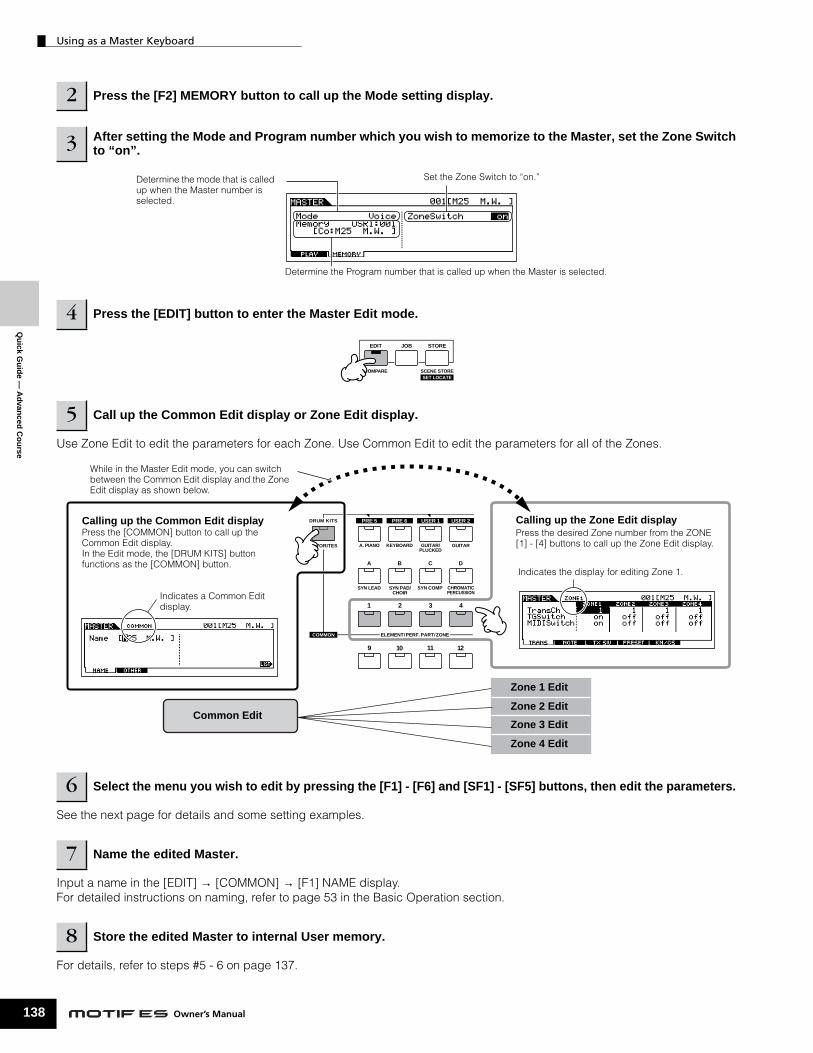
Qu
ick Gu
ide —
Ad
vanced
Co
urse
Using as a Master Keyboard
138
Use Zone Edit to edit the parameters for each Zone. Use Common Edit to edit the parameters for all of the Zones.
See the next page for details and some setting examples.
Input a name in the [EDIT] → [COMMON] → [F1] NAME display. For detailed instructions on naming, refer to page 53 in the Basic Operation section.
For details, refer to steps #5 - 6 on page 137.
2 Press the [F2] MEMORY button to call up the Mode setting display.
3 After setting the Mode and Program number which you wish to memorize to the Master, set the Zone Switch to “on”.
4 Press the [EDIT] button to enter the Master Edit mode.
5 Call up the Common Edit display or Zone Edit display.
6 Select the menu you wish to edit by pressing the [F1] - [F6] and [SF1] - [SF5] buttons, then edit the parameters.
7 Name the edited Master.
8 Store the edited Master to internal User memory.
Determine the mode that is called up when the Master number is selected.
Set the Zone Switch to “on.”
Determine the Program number that is called up when the Master is selected.
EDIT
COMPARE SCENE STORESET LOCATE
JOB STORE
COMMON ELEMENT/PERF. PART/ZONE
FAVORITES
DRUM KITS
A. PIANO KEYBOARD GUITAR/PLUCKED
PRE 5 PRE 6 USER 1
GUITAR
SYN LEAD
A B C D
4321
1211109
SYN PAD/CHOIR
SYN COMP CHROMATICPERCUSSION
USER 2Calling up the Common Edit displayPress the [COMMON] button to call up the Common Edit display. In the Edit mode, the [DRUM KITS] button functions as the [COMMON] button.
While in the Master Edit mode, you can switch between the Common Edit display and the Zone Edit display as shown below.
Calling up the Zone Edit displayPress the desired Zone number from the ZONE [1] - [4] buttons to call up the Zone Edit display.
Indicates a Common Edit display.
Indicates the display for editing Zone 1.
Common Edit
Zone 1 Edit
Zone 2 Edit
Zone 3 Edit
Zone 4 Edit
Owner’s Manual

Using as a Master Keyboard
Qu
ick
Gu
ide
— A
dva
nce
d C
ou
rse
Using Zones effectively with external
The two examples below show how to use the Zones with both the internal tone generator and a connected external tone generator. These instructions correspond to step #6 on the previous page.
n Though all four Zones are used in the example below, you can use any number of Zones (two, three, or four). The settings are made with the MIDISwitch parameter ([MASTER] → [EDIT] → Zone selection → [F1] TRANS → MIDISwitch) and the TGSwitch parameter ([MASTER] → [EDIT] → Zone selection → [F1] TRANS → TGSwitch).
n In these examples, the Zones are assigned to different areas of the keyboard. However, two or more Zones can also be assigned to the same area in a layer, from the NOTE display ([MASTER] → [EDIT] → Zone selection → [F2] NOTE).
■ Master settings with the Voice mode/Performance mode (Single-timbre tone generator mode)
■ Master settings with the Song mode/Pattern mode (Multi-timbral tone generator mode)
For each Zone, set whether or not MIDI data is transmitted to the external instrument.
Corresponds to step #6 on the previous page
Determine the MIDI Transmit Channel for each zone.[MASTER] → [EDIT] → Zone selection → [F1] TRANS → TransCh
For each Zone, set whether or not MIDI data is transmitted to each Part of the internal tone generator.[MASTER] → [EDIT] → Zone selection → [F1] TRANS → TGSwitch
Determine the note range of each zone.[MASTER] → [EDIT] → Zone selection → [F2] NOTE → NoteLimitH[MASTER] → [EDIT] → Zone selection → [F2] NOTE → NoteLimitL
[MASTER] → [EDIT] → Zone selection → [F1] TRANS → MIDISwitch
Internal tone generator (Single Timbre)
External tone generator (Multi-timbral)Set the MIDI receive channel for each part.
MIDI Transmit Channel 1
MIDI Transmit Channel 2
MIDI Transmit Channel 3
MIDI Transmit Channel 4
[UTILITY] → [F5] MIDI → [SF1] CH → BasicRcvCh = 01
For each Zone, set whether or not MIDI data is transmitted to the external instrument.
Corresponds to step #6 on the previous page
Determine the MIDI Transmit Channel for each zone.[MASTER] → [EDIT] → Zone selection → [F1] TRANS → TransCh
For each Zone, set whether or not MIDI data is transmitted to each Part of the internal tone generator.[MASTER] → [EDIT] → Zone selection → [F1] TRANS → TGSwitch
Determine the note range of each zone.[MASTER] → [EDIT] → Zone selection → [F2] NOTE → NoteLimitH[MASTER] → [EDIT] → Zone selection → [F2] NOTE → NoteLimitL
[MASTER] → [EDIT] → Zone selection → [F1] TRANS → MIDISwitch
Internal tone generator (Multi-timbral)
External tone generator (Multi-timbral)Set the MIDI receive channel for each part.
MIDI Transmit Channel 1
Part 05Receive Channel 1
Part 13Receive Channel 2
MIDI Transmit Channel 2
MIDI Transmit Channel 3
MIDI Transmit Channel 4
[SONG] → [MIXING] → [EDIT] → Part selection → [F1]VOICE → [SF2]MODE → ReceiveCh
139Owner’s Manual

Qu
ick Gu
ide —
Ad
vanced
Co
urse
Using as a Master Keyboard
140
Assigning Control Change numbers to the Knobs/Sliders for each Zone
Here in the KN/CS display of the Master Edit mode, you can set how the Control Knobs and Sliders will affect each Zone. This lets you specify a separate MIDI Control Change number for each Knob and Slider. Set the parameters as shown below, corresponding to step #6 on page 138.
In the example above, the Control Knobs for all Zones have been set to 10 (Pan), and the Sliders have been set to 11 (Expression). In this way, you can control the stereo position of each Zone with the appropriate Knob, and use the Sliders to adjust the relative volume balance among the Zones.
KNOBCONTROLFUNCTION
MASTERVOLUME
SWING
CUTOFF
PAN
ASSIGN A
GATE TIME
RESONANCE
REVERB
ASSIGN B
VELOCITY
ATTACK
CHORUS
ASSIGN 1
UNITMULTIPLY
RELEASE
TEMPO
ASSIGN 2
LOW
KN 1LOW MID
KN 2HIGH MID
KN 3HIGH
KN 4
ARP FX
EQ
TONE
ASSIGN
PAN/SEND
ZONE 1
CS 1
ZONE 1 ZONE 1 ZONE 1ZONE 1
CS 1 CS 2
ZONE 2
CS 3
ZONE 3
CS 4
ZONE 4
VOLUME 1 VOLUME 1 VOLUME 1 VOLUME 1VOLUME 1 VOLUME 2 VOLUME 3 VOLUME 4All indicators are turned off by setting the [MASTER] → [EDIT] → [COMMON] → [F2] OTHER → Knob/Slider parameter to “zone.”
You can determine which Control Change numbers are used for the Knobs and Sliders for each zone in the [MASTER] → [EDIT] → Zone selection → [F5] KN/CS display.
Owner’s Manual

Using as a Master Keyboard
Qu
ick
Gu
ide
— A
dva
nce
d C
ou
rse
Setting up the Master Zones to Split or Layer
This operation lets you easily determine whether the Zones of the selected Master are to be used in a Split or a Layer. The note range settings for each Zone can be determined by setting the NoteLimitH and NoteLimitL parameters from the NOTE display ([MASTER] → [EDIT] → Zone selection → [F2] NOTE).
n Zones 1 and 2 are used in the explanations here.
1 In the Master Play mode, press the [JOB] button to enter the Master Job mode.
2 Press the [F1] INIT button to call up the Initialize display.
3 Uncheckmark the box of “All” by using the [DEC/NO] button and checkmark the box of “Zone.”
4 Set the Type to “Split” or “Layer.”
When Type is set to “Split”Set the UpperCh (MIDI transmit channel of the upper range), LowerCh (MIDI transmit channel of the lower range), and Split Point (which separates the keyboard into the upper range and lower range).
When Type is set to “Layer”Set the UpperCh (MIDI transmit channel of Zone 1) and LowerCh (MIDI transmit channel of Zone 2).
5 Press the [ENTER] button. (The display prompts you for confirmation.)To cancel the Job, press the [DEC/NO] button.
6 Press the [INC/YES] button to execute the Job. After the Job has been completed, a “Completed” message appears and operation returns to the original display.
Keep in mind that the Job may take a short time to complete, during which an “Executing..” or “Please keep power on” message may be shown. Never attempt to turn off the power while data is being written to Flash ROM while such a message is displayed. Turning the power off in this state results in loss of all user data and may cause the system to freeze (due to corruption of data in the Flash ROM). This may also result in the MOTIF ES being unable to properly start up the next time the power is turned on.
TIP
Lower Upper
Split Point(C3)
Layer (Upper)
Layer (Lower)
CAUTION
141Owner’s Manual

Qu
ick Gu
ide —
Co
mp
uter ap
plicatio
ns
Setting up
142
Although the MOTIF ES is a powerful instrument in its own right and can effectively be used by itself for music creation and production, it is also designed for easy and comprehensive interfacing with a computer system. In this section, we’ll show you how set up the instrument with a computer (via USB) and how to use it with the software provided on the included CD-ROM, “Tools for MOTIF ES.”
n For information on how to install each software and the minimum system requirements, refer to the separate Installation Guide.
n About how to use each software, refer to the relevant documentation (PDF manual or on-line Help).
n By installing an optional mLAN16E board and using the mLAN connection with your computer, you can transfer both audio and MIDI data between the devices over the same mLAN cable. See page 39.
Setting up
Quick Guide — Computer applications
• For software on the included “Tools for MOTIF ES” CD-ROM (Voice Editor, USB MIDI driver, etc.), refer to the separate Installation Guide.
• For other software, refer to the relevant manual or documentation.
n You can also connect the instrument to a computer by using MIDI cables (page 40) or IEEE1394 cable (page 39).
• For a computer running Windows, the Add New Hardware Wizard may appear on the computer display. In this case, install the driver following the on-screen instructions. For details, refer to the separate Installation Guide.
• For a Macintosh computer, install OMS then install the USB MIDI driver. Refer to the separate Installation Guide.
n If you have installed the optional mLAN16E and are connecting the instrument to a computer with an IEEE 1394 cable, you’ll need to install the mLAN driver.
1 Confirm the minimum system requirements of the software you wish to use.
2 Connect the computer to the instrument with a USB cable.
3Start the computer and insert the “Tools for MOTIF ES” CD-ROM into the CD drive of the computer.
4 Turn the power of the MOTIF ES on.
5 Install the USB MIDI driver to the computer.
USB
TO HOSTTO DEVICE
USB connector
A type USB cable B type
Rear panel
USB TO HOST connector
Owner’s Manual
• To install software from the included “Tools for MOTIF ES” CD-ROM (Voice Editor, SQ01, etc.), refer to the separate Installation Guide.
• To install other software, refer to the relevant manual or documentation.
The settings in the Utility mode are stored as system settings to internal Flash ROM. Never attempt to turn off the power while data is being written to Flash ROM (while a “Please keep power on” message is shown). Turning the power off in this state results in loss of all user data and may cause the system to freeze (due to corruption of data in the Flash ROM). This may also result in the MOTIF ES being unable to properly start up the next time the power is turned on.
6 Install the desired software to the computer.
7Set the MIDI IN/OUT parameter to “USB” ([UTILITY] →→→→ [F5] MIDI →→→→ [SF4] OTHER), then press the [ENTER] button to store the Utility settings.
EDIT
COMPARE SCENE STORESET LOCATE
JOB STORE
USB
CAUTION

Controlling the instrument from a computer
Controlling the instrument from a computerUsing a sequencer to play multiple Voices on the MOTIF ES
The sequence software program SQ01 contained in the included CD-ROM lets you create and edit multi-part song data — which can be played using the sounds of the MOTIF ES.
— C
om
pu
ter
app
licat
ion
s
Refer to the separate Installation Guide.
For details on the MIDI settings, refer to the separate Installation Guide.For details on synchronization settings, refer to the on-line help of the SQ01.
From the “File” menus on the SQ01, select “Open” to call up the dialog box. Then select the desired song file.
1Follow the instructions described in “Setting up for using a computer” (page 142) then install the SQ01 to the computer.
2 Start the SQ01 on the computer then set all MIDI-related parameters, including synchronization.
3 Open the desired song file on the SQ01.
These settings make it possible for the Songs and Patterns on the MOTIF ES to start, play and stop in exact synchronization with the external controlling device (in this case, the computer sequencer).
Click the [F] (PLay) button on the SQ01 to start the selected song.
4Set the MIDI Sync parameter to “MIDI” and SeqCtrl to “in” in the SYNC display ([UTILITY] →→→→ [F5] MIDI →→→→ [SF3] SYNC).
5 Press the [SONG] button to enter the Song mode.
6 Start the song playback on the SQ01.
Qu
ick
Gu
ide
Recording sequencer song data to Song tracks on the MOTIF ES
If you have MIDI sequence data on your computer and want to use it as a Song on the MOTIF ES, you can play back the data on a MIDI sequencer (such as the SQ01) and record it to the MOTIF ES.
TIP
1 Follow the instructions described in “Setting up for using a computer” (page 142).
2 Start the SQ01 on the computer then set all MIDI-related parameters, including synchronization.For details on the MIDI settings, refer to the separate Installation Guide.For details on synchronization settings, refer to the on-line help of the SQ01.
3 Open the desired song file on the SQ01. From the “File” menus on the SQ01, select “Open” to call up the dialog box. Then select the desired song.
4 Set the MIDI Sync parameter to “MIDI” and the SeqCtrl to “in” in the SYNC display ([UTILITY] →→→→ [F5] MIDI →→→→ [SF3] SYNC).These settings make it possible for the Songs and Patterns on the MOTIF ES to start, play and stop in exact synchronization with the SQ01.
5 Press the [SONG] button to enter the Song Play mode, then select a Song to be recorded.
6 Press the [● ] (Record) button to enter the Song Record mode.
7 Set RecTrack to “multi.” This setting makes it possible to record MIDI sequence data to 16 tracks simultaneously.
8 Start song playback on the SQ01. Song recording on the MOTIF ES automatically starts at the same time.
9 Stop the song playback on the SQ01. Song recording on the MOTIF ES automatically stops at the same time.
10 Save the recorded song on the MOTIF ES. Before selecting a different Song, store the Mixing settings as Song data (page 131). Before turning the power off, save the recorded Song to a SmartMedia/USB storage device (page 132).
143Owner’s Manual

Qu
ick Gu
ide —
Co
mp
uter ap
plicatio
ns
Controlling the instrument from a computer
144
Using the Multi Part Editor to create/edit Mixing settings
The Multi Part Editor software (included on the CD-ROM) provides an intuitive way to create and edit the Mixing settings of the currently selected Song or Pattern. Thanks to the easy-to-understand graphical interface, you can edit virtually all of the Mixing parameters right from your computer – using the mouse to adjust the virtual knobs, sliders, and buttons and entering values from the computer keyboard.
n If you want to assign a User Voice to a Part, make sure to transfer the User Voice data on the MOTIF ES to the computer (with the Bulk Dump function) before editing parameters on the Multi Part Editor.
n Parts to which Mixing Voices have been assigned cannot be edited with the Multi Part Editor.
MUSIC PRODUCTION SYNTHESIZER
Edit the Mixing
To edit Mixing settings based on data saved to computer, make sure to transfer the Mixing data to the current Song/Pattern on the MOTIF ES (with the Bulk Transmission function) before editing.
To edit Mixing settings based on data contained on the MOTIF ES, make sure to transfer the Mixing data of the current Song/Pattern to the computer (with the Bulk Dump function) before editing.
Save a set of Mixing settings as a single file.
After storing the Mixing settings as a Song Mixing/Pattern Mixing, save all the Songs/Patterns.
SmartMedia/USB storage device
For details about how to install the Multi Part Editor, refer to the separate Installation Guide.
Refer to the PDF manual of the Multi Part Editor.
Refer to the PDF manual of the Multi Part Editor.
Refer to the PDF manual of the Multi Part Editor.
1Follow the instructions described in “Setting up for using a computer” (page 142) then install the Multi Part Editor to the computer.
2Enter the Song mode or Pattern mode on the MOTIF ES, then select the desired Song or Pattern.
3 Start the Multi Part Editor on the computer.
4 Set the MIDI related parameters on the Multi Part Editor.
5 Edit the parameters on the Multi Part Editor to create your original Mixing.
6Check the results of your edits by playing the Song/Pattern or playing the keyboard on the MOTIF ES.
Owner’s Manual
Press the [MIXING] button then [STORE] button to enter the Song Mixing mode/Pattern Mixing mode, then press the [ENTER] button to execute the Store operation.
n You can store the settings as a Mixing Template. See page 132.
7 Store the edited Mixing settings to the current Song Mixing/Pattern Mixing.
8 Save all the songs or patterns to a SmartMedia/USB storage device.
9 Also save the edited data as a Multi Part Editor file to your computer’s hard disk.

Controlling the instrument from a computer
Co
mp
ute
r ap
plic
atio
ns
Using the Voice Editor to create/edit a Voice
The Voice Editor software (included on the CD-ROM) provides an intuitive way to create and edit Voices for the MOTIF ES. Thanks to the easy-to-understand graphical interface, you can edit virtually all of the Voice parameters right from your computer – using the mouse to adjust the virtual knobs, sliders, and buttons and entering values from the computer keyboard.
MUSIC PRODUCTION SYNTHESIZER
Edit the Voice Use the Bulk Transmission function to transfer the edited Voice data (in a Voice bank) to the MOTIF ES.
Library file = Voice Editor file (extension: W7E)All voices stored on internal User memory are saved to a single file which can be loaded to the Voice Editor on the computer.
Load a Library file (extension: W7E).
Save the result of editing as a Library file (extension: W7E).
Load a Voice Editor file (extension: W7E).
Save the result of editing as a Voice Editor file (extension: W7E).
Use the Bulk Receive function to transfer the specified User Voice bank from the MOTIF ES to the computer.
SmartMedia/USB storage device
Qu
ick
Gu
ide
—
For details about how to install the Voice Editor, refer to the separate Installation Guide.
Refer to the PDF manual of the Multi Part Editor.
Refer to the PDF manual of the Voice Editor.
Create a new Library file or open an existing Library file. To edit data contained on the MOTIF ES, use the Bulk Receive function to transfer User Voice data to the computer.For details, refer to the PDF manual of the Voice Editor.
1Follow the instructions described in “Setting up for using a computer” (page 142) then install the Voice Editor to the computer.
2 Enter the Voice mode on the MOTIF ES, then start the Voice Editor on the computer.
3 Set the MIDI related parameters on the Voice Editor.
4 Call up the Voice data to be edited on the Voice Editor.
Refer to the PDF manual of the Voice Editor.
Refer to the PDF manual of the Voice Editor.
The Bulk Transmission from the computer to the MOTIF ES will erase (overwrite) the destination Voice Bank data on the MOTIF ES. If you wish to maintain the voices of the destination Bank, save the Voice data to a SmartMedia/USB storage device before executing Bulk Transmission.
5 Edit the parameters on the Voice Editor to create your original Voice.
6After editing the Voice, store the data, then transfer it to the MOTIF ES with the Bulk Transmission function on the Voice Editor.
7 Save the edited data as a Library file to your computer’s hard disk.
8Check the results of your edits by selecting the User Voice and playing the keyboard in the Voice Play mode.
CAUTION
145Owner’s Manual

Controlling the instrument from a computer
146
Qu
ick Gu
ide —
Co
mp
uter ap
plicatio
ns
Editing Plug-in Voices and Board VoicesAs described on page 76, the voices of a Plug-in Board installed to the MOTIF ES can be divided into two types: Board voices and Plug-in voices. Plug-in Voices can be edited in the Voice Edit mode on the MOTIF ES or can be edited by using the Voice Editor on the computer. Board Voices, however, are edited using the dedicated editor software contained on the included CD-ROM, “TOOLS for Modular Synthesis Plug-in System.”
Using the TWE Wave Editor to edit Samples
The TWE wave editing software (included on the CD-ROM) lets you edit audio on your computer and save them as samples for use with the MOTIF ES. Thanks to the easy-to-understand graphical interface, you can edit virtually all of the wave parameters right from your computer.
n For details on how to install TWE and the minimum system requirements, refer to the separate Installation Guide.
n For information on how to use TWE, refer to the TWE manual (PDF format) on the CD-ROM.
MUSIC PRODUCTION SYNTHESIZER
■ Plug-in Voice
■ Board Voice
Plug-in Board
Edit in the Voice Playmode/Voice Edit.
Voice Play display
Voice Edit display
Use the Voice Editor containedin the included CD-ROM, “TOOLS for MOTIF ES6/7/8.”
SmartMedia/USBstorage device
Use the dedicated Editorcontained in the includedCD-ROM, “TOOLS for Modular SynthesisPlug-in System.”
Save
Select and call up
Store
Select
Bulk transmission/Edit
Board CustomVoice
Board PresetVoice
or
MOTIF ES
Save*
* Set the file type to Plugin All Bulk 1, 2 or 3 (file extension: W2B)
Plug-inPreset Voice
Plug-inUser Voice
Computer
MUSIC PRODUCTION SYNTHESIZER
Edit the Wave using TWE
Save the result of editing as a WAV file or AIFF file.
SmartMedia/USB storage device
Load a WAV file or AIFF file.
Load a WAV file or AIFF file (page 100).
Save the sample as a WAV file or AIFF file (page 97).
Ow
ner’s Manual
Qu
ick
Gu
ide
— C
om
pu
ter
app
licat
ion
s
Controlling a computer from the instrument
Controlling a computer from the instrumentAs you’ve seen in previous sections, the MOTIF ES can be controlled from a computer. In this section, we’ll see how it can do the opposite — control the operation of music/audio software on the computer. This powerful feature lets you control two different software programs by using knobs, sliders and buttons on the panel of the MOTIF ES, rather than your computer’s mouse and keyboard. The MOTIF ES can be used to conrtol DAW (digital audio workstation) software, such as Cubase SX and SONAR, as well as the Multi Part Editor program (contained on the included CD-ROM). The Remote Control function on the instrument emulates that of the popular hardware controllers, Mackie Control, Logic Control and Yamaha 01X.
As shown in the example below, the MOTIF ES uses two of the four available USB ports to control two different software programs, while the two remaining ports handle MIDI sequence data.
MUSIC PRODUCTION SYNTHESIZER
REMOTE
ON/OFFR-AUDIOG-MIDI
DEC/NO INC / YES
SEQ TRANSPORT
LOCATE 1 2
USB cable
Mode A- Cubase, Port 4....
Mode B- General, Port 3....
Among other things, the Remote Control mode lets you start/stop the playback of the DAW software on the computer by using the SEQ TRANSPORT buttons and control the song position on the DAW software by using the data dial, [INC/YES] and [DEC/NO] buttons. For more information about the functions assigned to the panel buttons in the Remote Control mode, see page 151.
The functions of eight knobs/faders on the Mackie Control, Logic Control and 01X are assigned to the four Knobs/Sliders on the MOTIF ES. Pressing the [SF5] button changes which group's functions (1 - 4 or 5 - 8) are assigned to the four Knobs/Sliders. The eight knobs on the Mackie Control, Logic Control and 01X can also be used as switches. However, since the four Knobs on the MOTIF ES do not have switch capability, the [PRE1] - [PRE4] buttons are used instead. While the eight knobs on the emulated devices have “endless” rotary control, the four Knobs on the MOTIF ES stop at the minimum and maximum points. For some parameters this may mean that the value can’t be adjusted past certain points. If this occurs, you can use the data dial to adjust the value as desired. The data dial is active for the parameter corresponding to the Knob last turned.
Various functions are assigned to the [F1] - [F6] and [SF1] - [SF5] buttons depending on the DAW software to be controlled. The assigned functions are shown at the bottom of the display. For details, see page 151 and the separate Data List.
n As with the USB connection explained here, Remote Control can also be used with an IEEE1394 cable connection when the optional mLAN16E has been installed.
Press the REMOTE [ON/OFF] button (the lamp flashes) to enter the Remote Control mode. Press this button again to exit from the Remote Control mode.
Panel operations on the MOTIF ES control sequencer (Cubase SX) functions on the computer via MIDI port 4.
Panel operations on the MOTIF ES control mixing software (Multi Part Editor) functions on the computer via MIDI port 3. The “General” mode setting lets you control Yamaha software.
The MIDI data played back by the Cubase SX is trasferred to the MOTIF ES via the MIDI ports 1 and 2.
Multi Part Editor (Mixing software)
Cubase SX(DAW software)
Change the software (port) to be controlled.
USB TO HOST connector
Computer with a USB interface
147Owner’s Manual

Qu
ick Gu
ide —
Co
mp
uter ap
plicatio
ns
Controlling a computer from the instrument
148
■
Computer Software that can be controlled from the instrument
• For Windows • For Macintosh
Sett
Sett
The setmemorythat theStore o
The setFlash Rto Flashthe powsystemalso resthe pow
SQ01 V2 Logic 5.5
Cubase SX Digital Performer 3.1
SONAR 2.0
Multi Part Editor for MOTIF-RACK
Multi Part Editor for MOTIF ES6/7/8
1
2
3
4
5
C
C
Quick_04.fm Page 148 Wednesday, June 11, 2003 8:57 PM
ing up for Remote Control
ing up on the MOTIF ES Setting up on the computer
For details on the Yamaha software contained in the included CD-ROM, refer to the separate Installation Guide.
Set the MIDI IN/OUT parameter to “USB” ([UTILITY] →→→→ [F5] MIDI →→→→ [SF4] OTHER), When connecting the computer to the MOTIF ES via mLAN (with the optional mLAN16E installed), set this parameter to “mLAN.”
Call up the Remote Control Setup display by
1After following the instructions in “Setting up for using a computer” on page 147, install the desired software to your computer.
Owner’s Manual
tings in the Utility mode are actually stored on internal User (Flash ROM) by pressing the [STORE] button. Please keep in mind
settings will be lost if you turn off the power without executing the peration.
tings in the Utility mode are stored as system settings to internal OM. Never attempt to turn off the power while data is being written ROM (while a “Please keep power on” message is shown). Turning er off in this state results in loss of all user data and may cause the
to freeze (due to corruption of data in the Flash ROM). This may ult in the MOTIF ES being unable to properly start up the next time er is turned on.
For insreleva
Set thepage.For desoftwafollow
pressing the [F4] CTL ASN button, followed by the [SF4] REMOTE button.
Set the software to be controlled and Port number, referring to the illustration on the previous page.
Press the [ENTER] button to actually call up the settings made in step #3 above.
Press the [STORE] button to store the settings made in steps #1 and 4 above.
AUTION
AUTION
2
3
tructions on how to start the software, refer to the nt documentation.
MIDI port, referring to the illustration on the previous tails, refer to the documentation of the particular re. Instructions on how to set up the various software on the next page.
Enter the Song mode or Pattern mode on the MOTIF ES, then start the software on the computer.
Set the parameters related to MIDI and Remote Control on the computer software.

Controlling a computer from the instrument
Qu
ick
Gu
ide
— C
om
pu
ter
app
licat
ion
s
■ Cubase SX
1 Pull down the [Devices] menu and select [Device Setup] to call up the “Device Setup” window.
2 Click the [Add/Remove] tab and add the “Mackie Control.”
3 Select the added Mackie Control device and click the [Setup] tab.
4 When setting the Port to “4,” for example, in step #3 of “Setting up on the MOTIF ES,” set the MIDI Input to “YAMAHA USB IN 0-4” and the MIDI Output to “YAMAHA USB OUT 0-4.”
n The functions of buttons on the Mackie Control are assigned to the buttons of the MOTIF ES, with the exception of UserA and UserB (FootSw) which are not supported by the MOTIF ES.
■ SONAR
1 Pull down the [Options] menu and select [MIDI Devices] to call up the “MIDI Devices” window.
2 When setting the Port to “4” for example in step #3 of “Setting up on the MOTIF ES,” add “YAMAHA USB IN 0-4” to the “Inputs” and add “YAMAHA USB OUT 0-4” to the “Outputs.”
3 Pull down the [Options] menu and select [Control Surfaces] to call up the Control Surface window.
4 Click the “New” icon, select “Mackie Control,” then set the Input Port to “YAMAHA USB IN 0-4” and the Output Port to “YAMAHA USB OUT 0-4” (for example, when setting the Port to “4” in step #3 of “Setting up on the MOTIF ES”).
■ Digital Performer
1 Pull down the [Basics] menu and select [Control Surface Setup] to call up the “Control Surface” window.
2 Select “Mackie Control” in the Driver section. If Mackie Control is not available here, see the supplementary instructions below.
3 In the box for setting “Unit” and “MIDI,” select “Mackie Control” in the “Unit” section and select the MIDI port in the “MIDI” section.
When you cannot select “Mackie Control” in step #2:
1) Download the Mackie Control Plug-in software from “www.motu.com” and save it to your hard disk.
2) Move the Mackie Control file to the “Plug-ins” folder contained in the folder to which Digital Performer has been installed.
3) Start Digital Performer.
■ LogicWhen turning on the power of the MOTIF ES before starting Logic:
1 Set the software to be controlled to “Logic” in the Utility mode, then enter the Remote Control mode.
2 Start Logic on the computer. Logic automatically recognizes the MOTIF ES and performs the required settings.
When starting Logic before turning on the power of the MOTIF ES:
1 Start Logic on the computer, then turn the power to the MOTIF ES on. If you have already set the software to be controlled to “Logic” in the Utility mode, you need not perform step #2 because Logic automatically recognizes the MOTIF ES when this step is performed.
2 Set the software to be controlled to “Logic” in the Utility mode, then enter the Remote Control mode. Logic automatically recognizes the MOTIF ES and performs the required settings.
If for some reason Logic fails to recognize the MOTIF ES, follow the instructions below.
1) Select [Option] →→→→ [Preference] →→→→ [Control Surface] →→→→ [Install] from the menu.
2) Scan Logic Control on the window called up in step #1). When the scanning is successful, the Logic recognizes the MOTIF ES and performs the required settings automatically.
If Logic still fails to recognize the MOTIF ES even after performing the above instructions, follow the instructions below.
1) Select [Option] →→→→ [Preference] →→→→ [Control Surface] →→→→ [Install] from the menu.
2) Add Logic Control on the window called up in step #1).
3) Specify the Input Port and Output Port on the CONTROL SURFACE SETUP window called up in step #2).
■ SQ01For information about how to set the MIDI port, refer to the separate Installation Guide. For information on using Remote Control, follow the instructions below.
1 Select [Setup] →→→→ [Remote Control] to call up the Remote Control Setup window.
2 Select “01X” as mode, then set the Input Device/Output Device to the appropriate port number.
149Owner’s Manual

Controlling a computer from the instrument
150
Qu
ick Gu
ide —
Co
mp
uter ap
plicatio
ns
Functions assigned to the panel buttons in the Remote Control mode
To enter the Remote Control mode, press the REMOTE [ON/OFF] button (the lamp flashes). The REMOTE display appears (like those shown below), and the panel controls are enabled for Remote operation of the computer software (their normal functions are disabled).Press this button again to exit from the Remote Control mode.
REMOTE
ON/OFFR-AUDIOG-MIDI
REMOTE
ON/OFFR-AUDIOG-MIDI
SF5
F6
KNOBCONTROLFUNCTION
ARP FX
EQ
TONE
ASSIGN
PAN/SEND
Mode A Mode B
Edit the Wave
This button is available when the Mode is set to "General" and is used to switch between editing audio tracks (lamp is red) and MIDI tracks of the sequence software (lamp is green).
Changing the Mode(Changing the software to be controlled)
Change the Mode by pressing the REMOTE [ON/OFF] button while holding the [F6] SHIFT button.
This is the cursor which indicates the currently edited track/part by the knob/slider.Controlling the knob/slider moves the cursor to the corresponding track/part automatically. You can also move the cursor by using the Cursor [<] and [>] buttons.
Press the [KNOB CONTROL FUNCTION] button to change the functions assigned to the [F1] - [F6] and [SF1] - [SF5] buttons (shown at the bottom of the display). See page 151 for details.
Parameters and their values controlled by knobs/sliders are shown in two rows, in the boxes.
n Parameter names are shown according to the information transferred from the DAW software on the computer. The characters may be garbled depending on the DAW software or OS lamguage of your computer.
When [<<BANK] and [BANK>>] are shown here, you can use the [F4] and [F5] buttons to change the bank of eight tracks/parts (shown in the display) to be controlled.
Controlling the knob may change the [SF4] menu to indicate [DIAL]. When [DIAL] is shown here, the function of the last operated knob is assigned to the data dial, [INC/YES] and [DEC/NO] buttons. If you wish to restore these to the original function (song position control), press the [SF4] button to delete the [DIAL] menu.
To switch the cursor between the upper and lower row, press the [SF5] button.
Owner’s Manual

Controlling a computer from the instrument
The following explains which sequencer functions are assigned to which panel controls in the Remote Control mode.
■ SEQ TRANSPORT buttons ■ Control Sliders
Qu
ick
Gu
ide
— C
om
pu
ter
app
licat
ion
s
The Remote Control mode lets you start/stop playback of the DAW software on the computer by using the SEQ TRANSPORT buttons and control the song position on the DAW software by using the data dial, [INC/YES] and [DEC/NO] buttons.
n When the cursor is shown at any track/part in the boxes of two rows of the LCD display, the data dial, [INC/YES] and [DEC/NO] buttons function as the last operated knob and cannot be used to control the song position. To restore these to the original song position control, press the Cursor [<]/[>] buttons several times or press the [SF4] button (if the [DIAL] menu is shown) to delete the cursor.
■ Knob, Data dial, and [PRE1] - [PRE4] buttonsThe functions of eight knobs on the Mackie Control, Logic Control and 01X are assigned to the four Knobs on the MOTIF ES. Pressing the [SF5] button changes which group’s functions (1 - 4 or 5 - 8) are assigned to the four Knobs. When [<<BANK] and [BANK>>] are shown in the display, you can use the [F4] and [F5] buttons to change the bank of eight tracks/parts (shown in the display) to be controlled.
The eight knobs on the Mackie Control, Logic Control and 01X can also be used as switches. However, since the four Knobs on the MOTIF ES do not have switch capability, the [PRE1] - [PRE4] buttons are used instead. For convenience, the switch function corresponding to the last Knob operated is also assigned automatically to the [ENTER] button.
While the eight knobs on the emulated devices have “endless” rotary control, the four Knobs on the MOTIF ES stop at the minimum and maximum points. With some parameters this may mean that the value can’t be adjusted past certain points. If this occurs, you can use the data dial to adjust the value as desired. For convenience, the data dial is active for the parameter corresponding to the Knob last turned.
n To restore the function of the data dial, [INC/YES] and [DEC/NO] buttons to the original song position control, press the [SF4] button (if the [DIAL] menu is shown) to delete the cursor.
The functions of eight faders on the Mackie Control, Logic Control and 01X are assigned to the four Sliders on the MOTIF ES. Pressing the [SF5] button changes which group’s functions (1 - 4 or 5 - 8) are assigned to the four Sliders. When [<<BANK] and [BANK>>] are shown in the display, you can use the [F4] and [F5] buttons to change the bank of eight tracks/parts (shown in the display) to be controlled.
■ [F1] - [F6] buttons and [SF1] - [SF5] buttonsThe functions assigned to these buttons depends on the selected Mode (A or B) and the particular software being used (as set in step #3 in “Setting up on the MOTIF ES” on page 148).
When the Mode is set to “General,” these buttons are assigned to perform the same functions as panel buttons on the Yamaha 01X, for controlling various Yamaha music/audio software. The corresponding names of the 01X panel buttons are also indicated at the bottom of the display of the MOTIF ES.
When the Mode is set to “Logic,” these buttons are assigned to perform the same functions as panel buttons on the Logic Control, for controlling Logic on the computer. The corresponding names of the Logic Control panel buttons are also indicated at the bottom of the display of the MOTIF ES.
When the Mode is set to “Cubase” or “SONAR” or “D.Perf,” these buttons are assigned to perform the same functions as panel buttons on the Mackie Control, for controlling the corresponding software on the computer. The corresponding names of the Mackie Control panel buttons are also indicated at the bottom of the display of the MOTIF ES.
The function assignment can be changed by pressing the [KNOB CONTROL FUNCTION] buttons. The function assignment tables of the [F1] - [F6] buttons and [SF1] - [SF5] buttons for each DAW software are contained in the separate Data List.
n Among the functions assigned to the [F1] - [F6] buttons and [SF1] - [SF5] buttons, the functions indicated with brackets (such as [DIAL]) are not related to the Mackie Control, Logic Control and 01X but are unique to the MOTIF ES.
■ Data dial, [INC/YES] and [DEC/NO] buttonsAlthough the data dial and [INC/YES]/[DEC/NO] buttons are generally to change the song position on the DAW software, when you turn one of the Knobs on the MOTIF ES, the control function assigned to that Knob is automatically assigned to these panel controls as well, and the [DIAL] menu appears (at the [SF4] button). In this condition, these controllers cannot be used to control the song position. To restore the function of the data dial, [INC/YES] and [DEC/NO] buttons to the original song position control, press the [SF4] button (if the [DIAL] menu is shown) to delete the [DIAL] menu.
151Owner’s Manual

Qu
ick Gu
ide —
Co
mp
uter ap
plicatio
ns
Controlling a computer from the instrument
152
■ Cursor [<] and [>] buttonsBy moving the cursor left/right, you can change the track or part to controlled by the data dial and [INC/YES]/[DEC/NO] buttons. For example, when the cursor is at the upper box in the display, pressing the Cursor [.] button moves through the columns in succession (1, 2, 3, 4...). After 4, the cursor is hidden and wraps around to 1. When the cursor is shown in the display, the parameter at which the cursor is located can be edited by the data dial, [INC/YES] and [DEC/NO] buttons. When the cursor is hidden, the data dial and [INC/YES]/[DEC/NO] buttons can be used for their normal function — controlling the song position.
■ Cursor [ ] and [ ] buttonsWhen the Mode is set to “General,” the Cursor [ ]/[ ] buttons perform the same function as that of the DISPLAY [ ]/[ ] buttons on the 01X. When the Mode is set to something other than “General,” the Cursor [ ]/[ ] buttons perform the same function as that of the Cursor [ ]/[ ] buttons on the Mackie Control and Logic Control.
■ [EXIT] buttonWhen the Mode is set to “General,” this button performs the same function as that of the [PAGE SHIFT] button on the 01X. When the Mode is set to something other than “General,” the button has no control function.
■ BANK, GROUP and NUMBER buttonThese buttons are assigned to perform the same functions as the buttons directly over the faders on the 01X, Mackie Control and Logic Control.
[PRE1] - [PRE4] buttons
The eight knobs on the 01X, Mackie Control and Logic Control can also be used as switches. However, since the four Knobs on the MOTIF ES do not have switch capability, the [PRE1] - [PRE4] buttons are used instead.
[PRE5] - [PLG3] buttons
The functions of the eight [REC/RDY] buttons on the Mackie Control and Logic Control are assigned to these buttons. Please note that these buttons are not available when the Mode is set to “General.”
[A] - [H] buttons The functions of the eight [SOLO] buttons on the Mackie Control and Logic Control are assigned to these buttons. Please note that these buttons are not available when the Mode is set to “General.”
[1] - [8] and [TRACK SELECT] buttons
When the Mode is set to “General,” the functions of the nine [SEL] buttons on the 01X are assigned to these buttons. When the Mode is set to something other than “General,” the functions of the eight [MUTE] buttons on the Mackie Control and Logic Control are assigned to the [1] - [8] buttons.
[9] - [16] and [MUTE] buttons
When the Mode is set to “General,” the functions of the nine [ON] buttons on the 01X are assigned to these buttons. When the Mode is set to something other than “General,” the functions of the eight [SELECT] buttons on the Mackie Control and Logic Control are assigned to the [9] - [16] buttons.
Owner’s Manual
Checking the Remote Control assignmentsIf you’re unsure as to which software function has been assigned to a particular panel control on the MOTIF ES, this convenient feature lets you quickly check it from the display.
1 In the Remote Control mode, press the [INFORMATION] button to call up the information display, indicating the function of the last pressed button.
2 Press the button for which you want to check the assignment.
This display shown above appears when you press the [F] (Play) button of SEQ TRANSPORT. In this way, you can check each button’s control assignment simply by pressing it.
3 Press the [INFORMATION] button again to return to the Remote Control mode.
n While the Information display is shown, the panel buttons cannot be used to control the computer software.

Controlling a computer from the instrument
r ap
plic
atio
ns
Recording the sounds of the MOTIF ES to computer via mLANBy using the optional mLAN16E interface and an IEEE 1394 cable connection, you can record multitrack audio from the MOTIF ES to an mLAN-compatible DAW (digital audio workstation) program on your computer. This lets you transfer the audio data of multi-part Songs on the MOTIF ES to the DAW application for further editing and storage on your computer’s hard disk drive. In the example instructions below, Song playback and/or your keyboard performance in the Song mode can be recorded to the computer, on sepearate tracks of the DAW application.
Setup for connecting the computer to the MOTIF ES via mLAN
installed, these indicate the different audio channels
MUSIC PRODUCTION SYNTHESIZER
MOTIF ES Computer with an IEEE1394 interface
mLAN input
Audio signal of the MOTIF ES sound
mLAN16E
Qu
ick
Gu
ide
— C
om
pu
te
1 Install the optional mLAN16E to the MOTIF ES (page 288).
2 After turning the power on, set the MIDI IN/OUT parameter to “mLAN” ([UTILITY] →→→→ [F5] MIDI →→→→ [SF4] OTHER).
3 Press the [SONG] button to enter the Song mode and select the desired Song for playback, or the particular Mixing settings you want to use.
4 Set the mLAN MonitorSw parameter to “on” ([UTILITY] →→→→ [F2] I/O →→→→ [SF2] OUTPUT).When this parameter is set to on, the audio signal output via mLAN to the computer is also output to the external audio equipment via the main OUTPUT L/MONO and R jacks. This allows you to monitor the sound going to the computer with a set of headphones.
5 Determine the Output connector or channel of audio signal for each part. Make the desired OutputSel parameter settings ([SONG] → [MIXING] → [EDIT] → Part selection → [F2] OUTPUT → [SF3] SELECT). For example, set the OutputSel parameter for Part 1 to “as1&2,” Part 2 to “as3&4,” and Part 3 to “as5&6.”These settings (as1&2, as3&4, etc.) indicate the hardware output jacks on the optional AIEB2, when the device has been installed. When the mLAN16E is
Setup on the MOTIF ES
within the single mLAN connection.1 Connect the computer to the MOTIF ES using an IEEE1394 cable.
2 Install all necessary software to the computer, including the mLAN driver.Refer to the relevant documentation for the mLAN16E.
3 Install an mLAN-compatible audio sequencer or DAW application to the computer.Refer to the separate Installation Guide for information on how to install mLAN-compatible Yamaha applications.
4 Set the audio related parameters on the DAW software. Refer to the relevant documentation for the particular software.
Executing the Hard Disk RecordingAfter completing the setup described above, try out to record your keyboard performance to the hard disk of the computer by using the DAW software. For details about how to execute this, refer to the relevant document of the software.
Setup on the computer
153Owner’s Manual

Basic S
tructu
re
Internal Structure (System Overview)
154
This section gives you an easy-to-understand overview of the MOTIF ES — its wide range of sophisticated features, its MIDI control and performance functions, and its convenient file management system for original data you’ve created with the instrument.
Internal Structure (System Overview)This synthesizer is made up of several blocks, as shown here.
Controller supported by the MOTIF ES
Basic Structure
ZONE 1
CS 1
VOLUME 1 VOLUME 2 VOLUME 3 VOLUME 4
CS 2
ZONE 2
CS 3
ZONE 3
CS 4
ZONE 4
SWING GATE TIME VELOCITY UNITMULTIPLY
LOW
KN 1LOW MID
KN 2HIGH MID
KN 3HIGH
KN 4
Controller block
Keyboard Controllers
MIDI output
Audio (sound) output
Recording by the keyboard performance
Keyboard performance Operating the panel
Sequencer block Tone Generator blockMIDI sequence data
• Song• Pattern• Arpeggio
Internal AWM2 Plug-in board
• Voice• Performance
Sampling block
PlaybackEffect block
DSP
• Reverb• Chorus• Master Effect• Part Equalizer• Master Equalizer
Recording
External MIDI instrument
PlaybackMicrophone, Guitar, Bass, Audio equipment, etc.
Microphone, Guitar, Bass, Audio equipment, etc.
Audio signal flow
MIDI messages flow
Playback
Controller Block
This block consists of the keyboard, Pitch Bend and Modulation Wheels, Ribbon Controller, Knobs, Control Sliders and so on. The keyboard itself doesn’t generate sounds, but instead generates/transmits note on/off, velocity and other information (MIDI messages) to the synthesizer’s tone generator block when you play notes. The controllers also generates/transmits MIDI messages. The synthesizer’s tone generator block produces the sound according to the MIDI messages transmitted from the keyboard and controllers.
Owner’s Manual
The controllers you can use on this synthesizer and the reference pages are as follows:
● Controllers with which the MOTIF ES is equippedKeyboard (Initial Touch, Aftertouch) ................ page 18Pitch Bend Wheel ............................................ page 64Modulation Wheel ............................................ page 64Ribbon Controller............................................. page 65Knob (KN)........................................................ page 50Control Slider (CS)........................................... page 51
● Controllers (sold separately) that can be connected to the rear panel of the MOTIF ES Foot Controller ................................................. page 42Footswitch ....................................................... page 42Breath Controller.............................................. page 42

Bas
ic S
tru
ctu
re
Internal Structure (System Overview)
Controller related parameters in each mode
The chart below shows the operations for calling up the Controller related parameters in each mode. Parameters for the Footswitch and the Assign Knobs A/B apply to the entire instrument, regardless of the selected program (Voice/Performance/Song/Pattern).
Aside from their default control parameters, the controllers of the instrument, such as the Pitch Bend wheel and the Modulation wheel, can be freely assigned to a variety of different parameters. For example, you could assign Resonance to the Modulation Wheel and set aftertouch to apply vibrato. These settings for all the controllers are referred to as a “Controller Set,” and up to six Controller Sets can be created for each Voice.
● Source and Destination“source” refers to the hardware controller and “destination” refers to the parameter or function being controlled. An extensive variety of destination parameters are available, far more than those listed above. For a complete list of destination parameters, see the separate Data List.
Voice mode
Controller Set (for each Voice) [VOICE] → Voice selection → [EDIT] → [COMMON] → [F4] CTL SET See below.
Assigning the Control Change number to each Controller (for all Voices) [VOICE] → [UTILITY] → [F3] VOICE → [SF4] CTL ASN Page 262
Performance mode
Assigning the Control Change number to each Controller (for each Performance)
[PERFORM] → Performance selection → [EDIT] → [COMMON] → [F4] CTL ASN Page 214
Song mode Assigning the Control Change number to each Controller (for each Song Mixing)
[SONG] → Song selection → [MIXING] → [EDIT] → [COMMON] → [F4] CTL ASN Page 234
Pattern mode Assigning the Control Change number to each Controller (for each Pattern Mixing)
[PATTERN] → Pattern selection → [MIXING] → [EDIT] → [COMMON] → [F4] CTL ASN Page 248
All modes
Assigning the function and Control Change number to the Assign Knob A/B [UTILITY] → [F4] CTL ASN → [SF2] ASSIGN Page 263
Assigning the function and Control Change number to the Footswitch (connected to the ASSIGNABLE connector)
[UTILITY] → [F4] CTL ASN → [SF3] FT SW Page 263
Controller Set [VOICE] →→→→ Voice selection →→→→ [EDIT] →→→→ [COMMON] →→→→ [F4] CTL SET Page 192
SWING GATE TIME
LOW
KN 1LOW MID
KN 2
1ON/OFF ON/OFF ON/OFF ON/OFF
2 3 4
Voice
Controller Set 1 - 6
Volume, Reverb Send Level, Chorus Send Level, Filter Cutoff Frequency, Filter Resonance, etc.
Controller Set
Source = Controller
Depth = Degree to which the controller affects the sound
Element Switches
Destination (Dest) = functionn You can set whether the controller affects each
Element by setting the Element Switch on or off as desired. Note that this applies only to Normal Voices.
n The Element Switch parameters are not available when a function unrelated to Elements (1 - 40) is set as the destination.
155Owner’s Manual

Internal Structure (System Overview)
156
Basic S
tructu
re
● Using one source to control several destinationsFor example, set the Source parameter of Control Set 1 to MW (Modulation Wheel) and the Destination parameter to ELFO-PM (Element LFO Pitch Modulation Depth). Then set the Source parameter of Control Set 2 also to MW, but set the Destination parameter to ELM PAN (Element Pan). You will also need to specify the Element to be controlled and also the depth (amount) of control.In this example, when you move the Modulation Wheel upward, the amount of Pitch Modulation increases accordingly, and the Element is panned from left to right. In this way, you can have the sound change in several different ways, simply by adjusting a single controller.
● Using several sources to control one destinationFor example, set the Source parameter of Control Set 1 to MW (Modulation Wheel) and the Destination parameter to ELFO-PM (Element LFO Pitch Modulation Depth). Then set the Source parameter of Control Set 2 to FC (Foot Controller) and set the Destination parameter also to ELFO-PM (Element LFO Pitch Modulation Depth).Now, Pitch Modulation is assigned to both the Modulation Wheel and Foot Controller. In this way, you can have several different controllers affect the same aspect of the sound. This can be useful in live performance situations, letting you use any one of several controllers depending on which is convenient at the time.
n The Controller Set edited in the Voice Edit mode is available when the corresponding Voice is selected in the Performance mode, Song mode, and Pattern mode.
n The function assigned to the Controller by the Controller Set function can be applied only to the internal tone generator block. Operating the Controller will transmit the MIDI message (Control Change Number assigned below) to the external MIDI instrument.
Assigning Control Change numbers to the controllers
The functions assigned to the controllers by the Controller Set function can be applied only to the internal tone generator block. For connected external MIDI instruments, use of the controllers generates MIDI Control Change messages, as shown in the chart below.
* These Controllers are not used in the Controller Set function
As shown above, the keyboard Aftertouch, Pitch Bend Wheel, Modulation Wheel, Footswitch connected to the SUSTAIN connector, were originally designed for a particular purpose, and send pre-defined MIDI Control Change messages when used, regardless of their Control Set allocations within the synthesizer. For example, when the pan function is assigned to the Pitch Bend Wheel with the Controller Set, using the Pitch Bend Wheel will apply the pan function to the internal tone generator and will transmit the Pitch Bend messages to the external MIDI instrument. Using the other controllers will transmit the Control Change messages set from the display shown above to the external MIDI instrument while it will apply the functions set via the Controller Set to the internal tone generator block.
You can also set up a controller such that it sends one kind of Control message to the synthesizer’s internal tone generator yet another kind to the external MIDI instrument. For example, in a Controller Set you could assign Resonance to the ASSIGN Knob 1. Then, in the Utility mode, you could assign Control Change Number 1 (modulation) to the same knob. Now, when you turn the knob, resonance will be applied to the sound of the internal tone generator block; however, at the same time, modulation messages will be transmitted to the external MIDI instrument.
Controller Generated MIDI message Display
Aftertouch Channel Aftertouch (DnH) –
Pitch Bend Wheel Pitch Bend (EnH) –
Modulation Wheel Control Change (BnH, 01H) –
Footswitch (connected to the SUSTAIN connector)* Control Change (BnH, 40H) –
ASSIGN Knob A, B* Control Change (BnH) [UTILITY] → [F4] CTL ASN → [SF2] ASSIGN
Footswitch (connected to the ASSIGNABLE connector)* Control Change (BnH) [UTILITY] → [F4] CTL ASN → [SF3] FT SW
Ribbon Controller Control Change (BnH) [VOICE] → [UTILITY] → [F3] VOICE → [SF3] CTL ASN
ASSIGN Knob 1, 2 [PERFORM] → Performance selection → [EDIT] → [COMMON] → [F4] CTL ASN
Foot Controller 1, 2 [SONG] → Song selection → [MIXING] → [EDIT] → [COMMON] → [F4] CTL ASN
Breath Controller [PATTERN] → Pattern selection → [MIXING] → [EDIT] → [COMMON] → [F4] CTL ASN
Owner’s Manual

Bas
ic S
tru
ctu
re
Internal Structure (System Overview)
Tone Generator block
The Tone Generator block is what actually produces sound in response to the MIDI messages generated by playing the keyboard, using the controllers, and the playback of the sequencer (Song/Pattern/Arpeggio).
Internal AWM2 Tone Generator and optional Plug-in boards
The tone generator block in this synthesizer consists of the built-in AWM2 sound source and optional Plug-in Board(s).
● AWM2 (Advanced Wave Memory 2)AWM2 (Advanced Wave Memory 2) is a synthesis system based on sampled waves (sound material), and is used in many Yamaha synthesizers. For extra realism, each AWM2 Voice uses multiple samples of a real instrument’s waveform. Furthermore, a wide variety of parameters — envelope generator, filtert, modulation, and others — can be applied.You can also create your own waves (Samples) via microphone or from external audio equipment by using the Sampling function. These are then stored in internal memory (DRAM) and can be used just like the preset waves.
● Plug-in BoardFor details on using the optional Plug-in Boards for even more sounds, see page 74.
AMPFILTERPITCHOSC
Outputs the wave that makes up the sound.
To the Effect block
Changes the tonal quality of the sound output from the PITCH unit.
Controls the output level (amplitude) of the sound output from the FILTER unit. The signals are then sent at this level to the Effect block.
Controls the pitch of the sound.
Tone Generator
Internal AWM2Tone Generator
Plug-in boards (optional)
Up to three boards can be installed.
157Owner’s Manual

Basic S
tructu
re
Internal Structure (System Overview)
158
Voice, Performance, and Mixing
This instrument features three different types of programs, that form the basis for creating and playing sounds.
● VoiceA program that contains the sonic elements for generating a specific musical instrument sound is referred to as a “Voice.” Each Voice consists of up to four elements (Normal Voice) or up to 73 keys (Drum Voice). Each Voice is created by editing parameters unique to each element/key and parameters common to all the elements/keys in the Voice mode (page 188) or in the Mixing Voice mode (page 249).
● PerformanceA program in which multiple Voices (parts) are combined in a layer, or in other configurations is referred to as a
Owner’s Manual
“Performance.” Each Performance can contain up to four different parts (Voices). Each Performance can be created by editing parameters unique to each part and parameters common to all the parts in the Performance mode (page 212).
● MixingA program in which multiple Voices are assigned to Parts for multi-timbral play in the Song and Pattern modes is referred to as a “Mixing.” Each Mixing can contain up to 34 parts (page 163). Each Mixing can be created by editing parameters unique to each part and parameters common to all the parts in the Song Mixing mode (page 233) or in the Pattern Mixing mode (page 248).
n The Mixing belongs to the Song or Pattern.
The illustration below shows the structure and interrelationship of the Voices, Performances, and Mixings.
n The Drum Voice Key Edit parameters do not contain LFO settings.
CH16
CH1
VOICE
EG
PITCH
OSC(Oscillator)
FILTER AMP(Amplitude)
LFO
PEG FEG AEG
PERFORM SONG MIXING
PATTERN MIXING
One VoiceUp to four elements (Normal Voice)Up to 73 keys (Drum Voice)
Pitch Envelope Generator
One Mixing
Waveform (AWM2)
Common Edit parameters
Part Edit parameters
Part Edit parameters
Common Edit parameters
This synthesizer has two types of Voices – Voices created in the Voice mode and Mixing Voices (dedicated for the Song/Pattern) created in the Mixing Voice mode.
Common Edit parametersArpeggio, Effects, Controller Set, etc.
Element 1 - 4or Key C0-C6
• 1 - 16 parts (of the internal tone generator)
• 17 - 32 parts (of the optionally installed PLG100-XG)
• PLG1 - 3 parts (of the optionally installed single part Plug-in boards)
Filter Envelope Generator
Amplitude Envelope Generator
Low Frequency Oscillator
Different Voice for each part
One PerformanceUp to four parts
One Part
Voice
Different Voice for each part
One Part
Voice
Element Edit parametersor Key Edit parameters
Set in the Voice Edit mode (page 79)
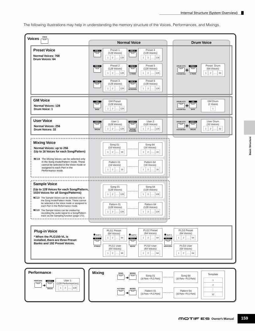
Bas
ic S
tru
ctu
re
Internal Structure (System Overview)
The following illustrations may help in understanding the memory structure of the Voices, Performances, and Mixings.
..................
..................
..................
..................
..................
..................
VOICE
Preset 1(128 Voices)
1 2 ...... 128
Preset 2(128 Voices)
1 2 ...... 128
Preset 3(128 Voices)
1 2 ...... 128
Preset 4(128 Voices)
1 2 ...... 128
Preset Drum(64 Voices)
1 2 ...... 64
GM Preset (128 Voices)
1 2 ...... 128
GM Drum(1 Voice)
1
User 1(128 Voices)
1 2 ...... 128
User 2(128 Voices)
1 2 ...... 128
Song 01(16 Voices)
1 2 ...... 16
Song 64(16 Voices)
1 2 ...... 16
Pattern 01(16 Voices)
1 2 ...... 16
Pattern 64(16 Voices)
1 2 ...... 16
Song 01(128 Voices)
1 2 ...... 128
Song 64(128 Voices)
1 2 ...... 128
Pattern 01(128 Voices)
1 2 ...... 128
Pattern 64(128 Voices)
1 2 ...... 128
User Drum(32 Voices)
1 2 ...... 32
Preset 5(128 Voices)
1 2 ...... 128
PLG1 Preset(64 Voices)
1 2 ...... 64
User 1(128 Performances)
1 2 ...... 128
PLG1 User(64 Voices)
1 2 ...... 64
PLG2 Preset(64 Voices)
1 2 ...... 64
PLG2 User(64 Voices)
1 2 ...... 64
PLG3 Preset(64 Voices)
1 2 ...... 64
PLG3 User(64 Voices)
1 2 ...... 64
Song 01(16 Parts + PLG Parts)
Pattern 01(16 Parts + PLG Parts)
Song 64(16 Parts + PLG Parts)
Template
1
2
......
32
Pattern 64(16 Parts + PLG Parts)
Preset 6(128 Voices)
1 2 ...... 128
ORGAN
USER 1PERFORM
SONG MIXING
PATTERN MIXING
STRINGS
PLG 1
SLOT 1 SLOT 2
BRASS
PLG 2
SLOT 3
REED/PIPE
PLG 3
ORGAN
USER 1
GUITAR/PLUCKED
USER 2
BASS
GM
PRE 1
PRE 2
PRE 3
PRE 4
A. PIANO
PRE 5
KEYBOARD
PRE 6
DRUM KITS
FAVORITES A. PIANO
PRE 5
DRUM KITS
FAVORITES BASS
GM
DRUM KITS
FAVORITES ORGAN
USER 1
➜
➜
➜
Normal Voice
The Sample Voices can be selected only in the Song mode/Pattern mode. These cannot be selected in the Voice mode or assigned to each Part in the Performance mode.
The Sample Voices can be created by recording the audio signal to a Song/Pattern track via the Sampling function (page 172).
Normal Voices: 768Drum Voices: 64
Drum VoiceVoices
Preset Voice
Normal Voices: 128Drum Voice: 1
GM Voice
Normal Voices: 256Drum Voices: 32
User Voice
(Up to 128 Voices for each Song/Pattern, 1024 Voices for all Songs/Patterns)
Sample Voice
* When the PLG150-VL is installed, there are three Preset Banks and 192 Preset Voices.
Plug-in Voice
Performance Mixing
Normal Voices: up to 256(Up to 16 Voices for each Song/Pattern)
Mixing Voice
The Mixing Voices can be selected only in the Song mode/Pattern mode. These cannot be selected in the Voice mode or assigned to each Part in the Performance mode.
159Owner’s Manual
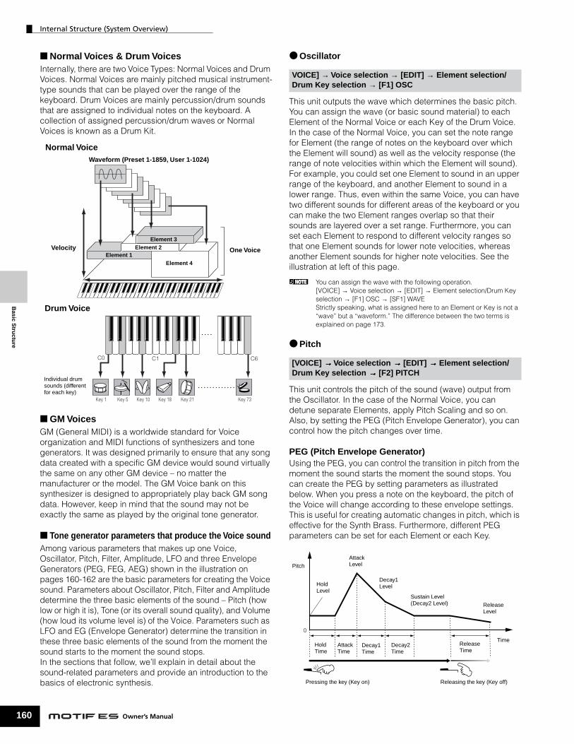
Basic S
tructu
re
Internal Structure (System Overview)
160
■ Normal Voices & Drum VoicesInternally, there are two Voice Types: Normal Voices and Drum Voices. Normal Voices are mainly pitched musical instrument-type sounds that can be played over the range of the keyboard. Drum Voices are mainly percussion/drum sounds that are assigned to individual notes on the keyboard. A collection of assigned percussion/drum waves or Normal Voices is known as a Drum Kit.
■ GM VoicesGM (General MIDI) is a worldwide standard for Voice organization and MIDI functions of synthesizers and tone generators. It was designed primarily to ensure that any song data created with a specific GM device would sound virtually the same on any other GM device – no matter the manufacturer or the model. The GM Voice bank on this synthesizer is designed to appropriately play back GM song data. However, keep in mind that the sound may not be exactly the same as played by the original tone generator.
■ Tone generator parameters that produce the Voice soundAmong various parameters that makes up one Voice, Oscillator, Pitch, Filter, Amplitude, LFO and three Envelope Generators (PEG, FEG, AEG) shown in the illustration on pages 160-162 are the basic parameters for creating the Voice sound. Parameters about Oscillator, Pitch, Filter and Amplitude determine the three basic elements of the sound – Pitch (how low or high it is), Tone (or its overall sound quality), and Volume (how loud its volume level is) of the Voice. Parameters such as LFO and EG (Envelope Generator) determine the transition in these three basic elements of the sound from the moment the sound starts to the moment the sound stops. In the sections that follow, we’ll explain in detail about the sound-related parameters and provide an introduction to the basics of electronic synthesis.
Key 1 Key 5 Key 10 Key 18 Key 21 Key 73
C0 C1 C6
Waveform (Preset 1-1859, User 1-1024)
Normal Voice
Individual drum sounds (different for each key)
Drum Voice
One Voice
Element 4Element 1
Element 2Element 3
Velocity
Owner’s Manual
● Oscillator
This unit outputs the wave which determines the basic pitch. You can assign the wave (or basic sound material) to each Element of the Normal Voice or each Key of the Drum Voice. In the case of the Normal Voice, you can set the note range for Element (the range of notes on the keyboard over which the Element will sound) as well as the velocity response (the range of note velocities within which the Element will sound). For example, you could set one Element to sound in an upper range of the keyboard, and another Element to sound in a lower range. Thus, even within the same Voice, you can have two different sounds for different areas of the keyboard or you can make the two Element ranges overlap so that their sounds are layered over a set range. Furthermore, you can set each Element to respond to different velocity ranges so that one Element sounds for lower note velocities, whereas another Element sounds for higher note velocities. See the illustration at left of this page.
n You can assign the wave with the following operation.[VOICE] → Voice selection → [EDIT] → Element selection/Drum Key selection → [F1] OSC → [SF1] WAVE Strictly speaking, what is assigned here to an Element or Key is not a “wave” but a “waveform.” The difference between the two terms is explained on page 173.
● Pitch
This unit controls the pitch of the sound (wave) output from the Oscillator. In the case of the Normal Voice, you can detune separate Elements, apply Pitch Scaling and so on. Also, by setting the PEG (Pitch Envelope Generator), you can control how the pitch changes over time.
PEG (Pitch Envelope Generator)Using the PEG, you can control the transition in pitch from the moment the sound starts the moment the sound stops. You can create the PEG by setting parameters as illustrated below. When you press a note on the keyboard, the pitch of the Voice will change according to these envelope settings. This is useful for creating automatic changes in pitch, which is effective for the Synth Brass. Furthermore, different PEG parameters can be set for each Element or each Key.
VOICE] → Voice selection → [EDIT] → Element selection/Drum Key selection → [F1] OSC
[VOICE] →→→→ Voice selection →→→→ [EDIT] →→→→ Element selection/Drum Key selection →→→→ [F2] PITCH
0
Pitch
Hold Level
AttackLevel
Decay1Level
Sustain Level(Decay2 Level) Release
Level
HoldTime
AttackTime
Decay1Time
Decay2Time
ReleaseTime
Time
Pressing the key (Key on) Releasing the key (Key off)

Internal Structure (System Overview)
Bas
ic S
tru
ctu
re
● Filter
This unit modifies the tone of the sound output from Pitch by cutting the output of a specific frequency portion of the sound.
Cutoff Frequency and ResonanceHere’s how filters work. In the example below (a low pass filter), a portion of the signal lower than a given frequency is allowed to pass, and signals above that frequency are cut. This frequency is referred to as the cutoff frequency. You can produce a relatively bright or darker sound by setting the cutoff. Resonance is a parameter that boosts the level of the signal in the area of the cutoff frequency. By emphasizing the overtones in this area, this can produce a distinctive “peaky” tone, making the sound brighter and harder.
About the main Filter typesThe Low Pass Filter is shown in the illustration above – however, this synthesizer features other Filter types (four total) as shown below.
Low Pass Filter (above)This passes only those signals below the Cutoff frequency. You can then use the Reso (Resonance) parameter to add further character to the sound.
High Pass FilterThis passes only those signals above the Cutoff frequency. You can then use the Reso (Resonance) parameter to add further character to the sound.
[VOICE] → Voice selection → [EDIT] → Element selection/Drum Key selection → [F3] FILTER
These frequencies are “passed” by the filter.
Cutoff frequency
Resonance
Frequency (pitch)
Level
Frequency (pitch)Cutoff frequency
Level
Resonance
Cutoff frequency
These frequencies are “passed” by the filter.Level
Band Pass FilterThis passes only those a band of signals around the Cutoff frequency. The width of this band can be varied.
Band Elimination FilterThis attenuates a band of signals around the Cutoff frequency, but passes everything else.
FEG (Filter Envelope Generator)Using the FEG, you can control the transition in tone from the moment the sound starts to the moment the sound stops. You can create the FEG by setting parameters as illustrated below. When you press a note on the keyboard, the cutoff frequency will change according to these envelope settings. This is useful for creating automatic wah or filter sweep effects, for example. Furthermore, different FEG parameters can be set for each Element Key.
Frequency
Range passed
Cutoff range
Level
Center frequency
LevelCutoff range
Range passed
Center frequency Frequency
0
CutoffFrequency
Hold Level
AttackLevel
Decay1Level
Sustain Level(Decay2 Level) Release
Level
HoldTime
AttackTime
Decay1Time
Decay2Time
ReleaseTime
Time
Pressing the key (Key on) Releasing the key (Key off)
Owner
’s Ma 161nual
Basic S
tructu
re
Internal Structure (System Overview)
162
● Amplitude
This unit controls the output level (amplitude) of the sound output from Filter. The signals are then sent at this level to the Effect block. Also, by setting the AEG (Amplitude Envelope Generator), you can control how the volume changes over time.
AEG (Amplitude Envelope Generator)Using the AEG, you can control the transition in volume from the moment the sound starts is to the moment the sound stops. You can create the AEG by setting parameters as illustrated below. When you press a note on the keyboard, the volume will change according to these envelope settings. Furthermore, different AEG parameters can be set for each Element Key.
n When you release the key while holding the Footswitch connected to the SUSTAIN connector, the sound will maintain at the Sustain Level shown above. For Voices having a Sustain Level value greater than 0, the sound continues. For Voices having a Sustain Level of 0, the sound decays naturally to silence.
● LFO (Low Frequency Oscillator)
As its name suggests, the LFO produces a wave of a low frequency.These waves can be used to vary the pitch, filter or amplitude of each Element to create effects such as vibrato, wah and tremolo. LFO can be set independently for each Element; it can also be set globally for all Elements.
[VOICE] →→→→ Voice selection →→→→ [EDIT] →→→→ Element selection/Drum Key selection →→→→ [F4] AMP
[VOICE] → Voice selection → [EDIT] → Element selection/Drum Key selection → [F5] LFO
[VOICE] → Voice selection → [EDIT] → [COMMON] → [F5] LFO
0
Level(Volume)
Initial Level
AttackLevel
Decay1Level
Sustain Level(Decay2 Level)
TimeAttackTime
Decay1Time
Decay2Time
ReleaseLevel
ReleaseTime
Pressing the key (Key on) Releasing the key (Key off)
Owner’s Manual
Single Timbre Tone Generator (Voice/Performance mode) and Multi-timbral Tone Generator (Song/Pattern mode)
The internal tone generator block operates in two different ways (Single timbre and Multi-timbral) depending on the selected mode. The difference between the two is whether they can handle the multi-MIDI channels or not at the same time.
● Single Timbre Tone Generator (Voice/Performance mode)A MIDI tone generator that receives over a single MIDI channel and plays a single instrument part is referred to as a “single timbre” tone generator. This is the operating status of the internal tone generator in the Voice and Performance modes.
n To set the MIDI receive channel for single timbre operation (Voice and Performance modes), use the following operation in the Utility mode.[UTILITY] → [F5] MIDI → [SF1] CH → BasicRcvCh
● Multi-timbral Tone Generator (Song/Pattern mode)A MIDI tone generator that simultaneously receives over multiple MIDI channels and plays multiple instrument parts is referred to as a “multi-timbral” tone generator. This allows playback of mutli-channel MIDI song data — such as on a MIDI sequencer or computer — with each internal part being assigned to and played by a different track or channel. This is the operating status of the internal tone generator in the Song and Pattern modes.
n To set the MIDI receive channel for multi-timbral operation (Song and Pattern modes), use the following operation in the Utility mode.[SONG] or [PATTERN] → [MIXING] → [EDIT] → Part selection → [F1] VOICE → [SF2] MODE → ReceiveCh
n When using an external MIDI sequencer or computer to play this instrument, make sure to use the Song mode or Pattern mode.
Maximum PolyphonyMaximum polyphony refers to the highest number of notes that can be sounded simultaneously from the internal tone generator of the instrument.The maximum polyphony of this synthesizer is 128. When the internal tone generator block receives a number of notes exceeding the maximum polyphony, previously played notes are cut off. Keep in mind this may be especially noticeable with Voices not having decay.Furthermore, the maximum polyphony applies to the number of voice elements used, not the number of voices. When the normal voices that include up to four elements are used, the maximum number of simultaneous notes may be less than 128.
n When the Plug-in board is installed, the maximum polyphony increases accordingly. For details on maximum polyphony for the Plug-in Boards, refer to the Owner’s Manual of the particular board.

Internal Structure (System Overview)
Bas
ic S
tru
ctu
re
Part structure of the tone generator block
This synthesizer plays the sounds in the tone generator block in response to MIDI messages received from the controller or sequencer block. The MIDI messages are assigned to sixteen independent channels, and this synthesizer is capable of simultaneously playing sixteen separate parts, via the sixteen MIDI channels. However, the sixteen-channel limit can be overcome by using separate MIDI “ports,” each supporting sixteen channels. The multiple sound sources of this synthesizer (internal tone generator and Plug-in Boards) take advantage of the three MIDI ports included on the instrument.
As shown in the above illustration, up to 48 parts are provided for the modes (excepting the Voice mode). However, the number of parts that are actually used is a maximum of 34 in the Song and Pattern modes, as we will see later in some examples.
n The USB cable supports up to eight separate MIDI ports. The Tone Generator block of this synthesizer supports three separate ports as illustrated above.
n A single MIDI cable/connection cannot handle data over multiple MIDI ports.
■ Part structure of the tone generator block in the Voice mode
In this mode, a Voice is played from the keyboard, using a single part. This part is used also when the Plug-in Voice is selected. The tone generator block in the Voice mode receives MIDI data over a single channel. Keep in mind that song data on an external sequencer consisting of multiple MIDI channels will not play back properly in this mode. If you are using an external MIDI sequencer or computer to play the instrument, make sure to use the Song mode or Pattern mode.
Port 1
Part 1Part 2
Part 14Part 15Part 16
Port 2
Part 17Part 18
Part 30Part 31Part 32
Port 3
Part 33Part 34
Part 46Part 47Part 48
Tone Generator block
Parts used in modes other than the Voice mode
Part for Voice mode
Port 1
Part 1Part 2Part 3Part 4Part 5
Part 16
Port 2
Part 17Part 18
Part 30Part 31Part 32
Port 3
Part 33Part 34
Part 46Part 47Part 48
Tone generator block
Parts used in modes other than the Voice mode
Part for Voice mode
Parts 1-48 are not used.
n The MIDI receive channel in the Voice mode can be set from the following display in the Utility mode. [UTILITY] → [F5] MIDI → [SF1] CH → BasicRcvChThe MIDI port number which this synthesizer can recognize in the Voice mode is 1.
n The Multi-Part Plug-in Board (PLG100-XG) cannot be used in the Voice mode.
■ Part structure of the tone generator block in the Performance mode
This mode lets you play a Performance (which multiple Voices (parts) are combined – in a layer, or in other configurations) using the keyboard. While a total of seven parts are available in this mode (as shown below), a maximum of four parts can be used simultaneously. Although this mode lets you play several parts at the same time, all are set to receive over the same single MIDI channel, as in the Voice mode. For this reason, song data on an external sequencer consisting of multiple MIDI channels will not play back properly in this mode. If you are using an external MIDI sequencer or computer to play the instrument, make sure to use the Song mode or Pattern mode.
n The MIDI receive channel in the Performance mode can be set with the following operation in the Utility mode.[UTILITY] → [F5] MIDI → [SF1] CH → BasicRcvCh In the Voice mode, the instrument recognizes only data over MIDI Port 1.
n The Multi-part Plug-in Board (PLG100-XG) cannot be used in the Performance mode.
PLG1 part
PLG3 part
PLG2 part
Port 1
Part 1
Part 2
Part 3
Part 4
Part 5
Part 13
Part 14
Part 15
Part 16
Port 2
Part 17
Part 18
Part 30
Part 31
Part 32
Part 46
Part 47
Part 48
Port 3
Part 33
Part 34
PLG1
PLG3
PLG2
Tone generator blockWhen three single part Plug-in boards are installed to the synthesizer.
Parts 5-13 and 17-48 are not used.
These seven parts (1, 2, 3, 4, 14, 15, 16) are reserved for use in the Performance mode; however, only up to four of them can be used at the same time.
163Owner’s Manual

Internal Structure (System Overview)
164
Basic S
tructu
re
■ Part structure of the tone generator block in the Song mode/Pattern modeIn these modes, multiple parts are provided and different voice and different melodies or phrases can be played back for each part. Because these modes let you set the MIDI channel for each part of the tone generator block, you can use an external MIDI sequencer as well as the sequencer block of the instrument to play the sounds.As illustrated below, the sequence data of each track plays the corresponding parts (those having the same MIDI channel assignment) in the tone generator block.
The MIDI Transmit Channel/Port of the Song/Pattern can be set with the following operation.
When sounding the internal tone generator block, assign the tracks to Transmit Port 1 and use Parts 1 - 16. Keep in mind that data over Transmit Ports 2 or 3 cannot sound the internal tone generator block. The tone generator of the installed Plug-in Board can be sounded via any of the MIDI ports 1 - 3.
The MIDI Receive Channel of the tone generator’s part can be set with the following operation.
You can set the port number assignment for the Plug-in Board with the following operation.
n For details about MIDI, see page 181.
n The Plug-in Board lets you use only a single Voice at the same time. Please note that you cannot assign multiple Voices of the Plug-in Board to multiple parts at the same time.
n The Voice and related settings (volume, pan, etc.) are sounded by the keyboard according to the Part parameters in the Mixing settings of the current Song/Pattern and Part. Other settings such as Controllers and Effect types correspond to the Common parameters in the Mixing settings of the current Song/Pattern.
In the Song mode: [SONG] → Song selection → [F3] TRACK → [SF1] CHANNELIn the Pattern mode: [PATTERN] → Pattern selection → [F3] TRACK → [SF1] CHANNEL
In the Song mode: [SONG] → Song selection → [MIXING] → [EDIT] → Part selection → [F1] VOICE → [SF2] MODE → ReceiveChIn the Pattern mode: [PATTERN] → Pattern selection → [MIXING] → [EDIT] → Part selection → [F1] VOICE → [SF2] MODE → ReceiveCh
[UTILITY] → [F6] PLUG → [SF2] MIDI
Track 1 Transmit Channel = 1 (Port 1) Part 1 Receive Channel = 2
Port 1
Port 2
Port 3
Part 2 Receive Channel = 3
Part 3 Receive Channel = 4
Part 4 Receive Channel = 1
Part 15 Receive Channel = 5
Part 16 Receive Channel = 6
Part 17 Receive Channel = 8
Part 18 Receive Channel = 7
Part 19 Receive Channel = 10
Part 20 Receive Channel = 13
Part 31 Receive Channel = 14
Part 32 Receive Channel = 15
Part 33
Part 34
Part 35
Part 46
Part 47 Receive Channel = 11
Part 48 Receive Channel = 16
Track 2 Transmit Channel = 2 (Port 1)
Track 3 Transmit Channel = 3 (Port 1)
Track 4 Transmit Channel = 4 (Port 1)
Track 5 Transmit Channel = 5 (Port 1)
Track 6 Transmit Channel = 6 (Port 1)
Track 7 Transmit Channel = 7 (Port 2)
Track 8 Transmit Channel = 8 (Port 2)
Track 9 Transmit Channel = off (Port off)
Track 10 Transmit Channel = 10 (Port 2)
Track 11 Transmit Channel = 11 (Port 3)
Track 12 Transmit Channel = off (Port off)
Track 13 Transmit Channel = 13 (Port 2)
Track 14 Transmit Channel = 14 (Port 2)
Track 15 Transmit Channel = 15 (Port 2)
Track 16 Transmit Channel = 16 (Port 3)
Sequencer block (example)When setting the Transmit Channel/Port to the following example in the Song/Pattern mode or on the external MIDI sequencer or on the computer:
Tone Generator block (example)
When a Multi-part Plug-in Board (PLG100-XG) and a two Single part Plug-in Board are installed to this synthesizer and setting the Receive Channel/Port to the following example:
Multi-part Plug-in Board
Single part Plug-in Board
Single part Plug-in Board
Parts 33-46 are not used.
Owner’s Manual

Bas
ic S
tru
ctu
re
Internal Structure (System Overview)
Audio Input Part (AUDIO IN)The Performance mode, Song mode, and Pattern mode are capable of handling the audio input signal as a Part. Various parameters such as volume, pan, and effect can be set to this Part and the sound is output together with other Parts. Other available settings include how stereo input signals are handled, as well the output assignment of the audio Part. These parameters are set and stored for each Performance, Song Mixing, and Pattern Mixing. Please note that the Audio Input Part is not available in the Voice mode. Among the following three types of Audio Input parts which this synthesizer can handle, two types (five stereo parts if the mLAN16E has been installed) can be handled at the same time, since the optional mLAN16E and AIEB2 cannot be installed together.
Parameters for the above Parts can be set with the following operations.
n Although the Insertion Effects of this synthesizer can be applied to the A/D Input Part, they cannot be applied to the mLAN Input part and the AIEB2 Input part.
Sequencer Block
This block lets you create songs and patterns by recording and editing your performances as MIDI data (from the controller block), then playing it back with the tone generator block. The sequencer block can be operated in the Song mode, in the Pattern mode, and with the Arpeggio feature. When a Song or a Pattern is played back, the musical data of each sequence track is transmitted to the tone generator block according to the Transmit Channel settings.
n Songs can be played back only in the Song mode. They cannot be played back in other modes. Patterns can be played back only in the Pattern mode. They cannot be played back in other modes. Arpeggios can be played back in any modes.
Song and Pattern
Songs and Patterns are MIDI sequence data consisting of up to 16 tracks.A Song on this synthesizer is effectively the same as a Song on a MIDI sequencer, and playback automatically stops at the end of the recorded data.In the MOTIF ES, the term “Pattern” refers to a relatively short musical or rhythmic phrase — 1 to 256 measures — which is used for looped playback. Therefore, once Pattern playback starts, it continues until you press the [■ ] (Stop) button. This synthesizer features a variety of preset Phrase data that is used as the basic material in making up Patterns.
A/D Input part This part (one stereo part) is input from the external audio equipment connected to the A/D INPUT jack.
mLAN Input parts (when the optional mLAN16E has been installed)
These four stereo parts are input from external mLAN-compatible audio equipment connected to the mLAN jack via a single IEEE1394 cable.
AIEB2 parts (when the optional AIEB2 has been installed)
This part (one stereo part) is input from external audio equipment connected to the OPTICAL INPUT or the DIGITAL INPUT (Coaxial) connector. Either one of the connectors (OPTICAL or DIGITAL) can be used; however, both cannot be used at the same time. Select which connector is used for digital input with the following operation in the Utility mode.[UTILITY] → [F2] I/O → [SF1] INPUT → Digital
In the Performance mode [PERFORM] → Performance selection→ [EDIT] → [COMMON] → [F5] AUDIO IN
In the Song mode [SONG] → Song selection → [MIXING] → [EDIT] → [COMMON] → [F5] AUDIO IN
In the Pattern mode [PATTERN] → Pattern selection → [MIXING] → [EDIT] → [COMMON] → [F5] AUDIO IN
165Owner’s Manual

Basic S
tructu
re
Internal Structure (System Overview)
166
■ Song data structureThe following illustration shows the track structure of a Song. Songs are created by recording MIDI sequence data to individual tracks and by setting tone generator related parameters (in Song Mixing).
● Song Mixing ● Scene
Song 64
Musical performance data
Song Mixing (Tone Generator related settings)
Song 63
Song 02
Song 01
Tempo track
Track 1
Track 2
Track 3
Track 16
Part 1
Part 2
Part 3
Part 16
Mixing settings
Mixing settings
Mixing settings
Mixing settings
Part 17
Part 18
Part 19
Part 32
Mixing settings
Mixing settings
Mixing settings
Part PLG1
Part PLG2
Part PLG3
Audio Input part
Mixing settings
Mixing settings
Mixing settings
Mixing settings
Mixing settings
Mixing Voice 16
Mixing Voice 01
Please note that the Multi-part Plug-in Part (17-32) settings apply not to one individual Song but to all 64 Songs.
Set in the Song Play mode
Created in the Song Record mode, Song Edit mode, and Song Job mode
Created in the Mixing Voice Edit mode
Created in the Sampling mode entered from the Song mode
Set in the Song Mixing mode and Song Mixing Edit mode
MIDI sequence data
MIDI sequence data
MIDI sequence data
MIDI sequence data
Groove, Transmit Channel/Port, Track loop settings
Groove, Transmit Channel/Port, Track loop settings
Groove, Transmit Channel/Port, Track loop settings
Groove, Transmit Channel/Port, Track loop settings
Sample Voice
Sample Voice
Sample Voice
Sample Voice
Scene track
Tempo change
Scene 1 Scene 2 Scene 3 Scene 4 Scene 5
Mixing Common Edit Parameters applied to all the parts
Track mute status/Scene memory change/Arpeggio type change (including tempo, transpose, etc.)
Even if you record your keyboard performance to a Song track, the setup data (non-note events such as voice, pan, volume) which for proper playback should be recorded at the top of the Song will not be recorded to it. For this reason, the setup data handled as Song Mixing settings should be stored in the Song Mixing Store mode. Because the Song Mixing is a collection of settings related to the tone generator, it can be applied to the sequence data transmitted from the external MIDI sequencer as well as this synthesizer’s Song playback.
n When the Multi-Part Plug-in Board PLG100-XG has been installed, Mixing of sixteen parts (17 - 32) can be set. Please note that the Multi-part Plug-in Part (17 - 32) settings apply not to one individual Song but to all 64 Songs.
Owner’s Manual
A Song Scene is a “snapshot” of important settings, and contains parameter settings such as transpose, tempo, and track mute and the tone generator related parameters controllable from the Knobs with the [PAN/SEND] or [TONE] lamp turned on, and the Control Sliders. Five settings can be registered to the [SF1] - [SF5] buttons for each Song.
● Song ChainThis function allows songs to be “chained” together for automatic sequential playback. The Song Chain can be created and played back from the [SONG] → [F6] CHAIN display. This instrument allows you to create one Song Chain data.
Song 01 Song 22 Song 15

Internal Structure (System Overview)
Bas
ic S
tru
ctu
re
■ Pattern data structureThe following illustration shows the track structure of a Pattern. Patterns are created by recording MIDI sequence data to individual tracks, by assigning Phrases (Preset and User) which is material for a Pattern to individual tracks, and by setting tone generator related parameters (in a Pattern Mixing).
● Pattern Mixing ● Section
Mixing settings
Mixing settings
Mixing settings
Mixing settings
User Phrase 1 - 256(MIDI sequence data)
Mixing Common Edit Parameters applied to all the parts
Part 1 Mixing settings Part 17 Mixing settings
Part 18 Mixing settings
Part 19 Mixing settings
Part 32 Mixing settings
16 Sections
Mixing Voice 01
Mixing Voice 16
Part 2 Mixing settings
Part 3 Mixing settings
Part 16 Mixing settings
Pattern Chain
Part PLG1
Part PLG2
Part PLG3
Audio Input part
Mixing settings
Mixing settings
Mixing settings
Mixing settings
A B P
Set in the Pattern Play mode
Created in the Pattern Record mode, Pattern Edit mode, and Pattern Job mode
Created in the Mixing Voice Edit mode
Created in the Sampling mode entered from the Pattern mode
Created in the Pattern Chain mode
Set in the Pattern Mixing mode and Pattern Mixing Edit mode
Pattern 64
Pattern 01
Groove, Transmit Channel/Port, Track loop, Track Voice settings
User Phrase 1 - 256(MIDI sequence data)
Preset Phrase 1 - 687(MIDI sequence data)
Mixing Common Edit Parameters applied to all the parts
Please note that the Multi-part Plug-in Part (17-32) settings apply not to one individual Pattern but to all 64 Patterns.
Copy the Phrase recorded to a track of another pattern
The Patch function lets you assign a Phrase to each track.
Track 1 MIDI sequence data
Track 2 MIDI sequence data
Track 3 MIDI sequence data
Track 16 MIDI sequence data
User Phrase
Preset Phrase
Sample Voice
Pattern Mixing (Tone Generator related settings)
Even if you record your keyboard performance to a Pattern track, the setup data (non-note events such as voice, pan, volume) which for proper playback should be recorded at the top of the Pattern will not be recorded to it. For this reason, the setup data handled as Pattern Mixing settings should be stored in the Pattern Mixing Store mode. Unlike the Song, only the voice number is recorded to a track as a Track Voice (Phrase Voice) which is used for playback normally. Because the Pattern Mixing is a collection of settings related to the tone generator, it can be applied to the sequence data transmitted from the external MIDI sequencer as well as this synthesizer’s Pattern playback.
n When the Multi-Part Plug-in Board PLG100-XG has been installed, Mixing of sixteen parts (17 - 32) can be set. Please note that the Multi-Part Plug-in Part (17 - 32) settings apply not to one individual Pattern but to all 64 Patterns.
A Pattern consists of one or more “Sections” (Pattern variations). You can play the Pattern by specifying a Section after selecting a Pattern.
● PhraseThis is the basic MIDI sequence data – and the smallest unit – used in creating a Pattern. “Phrase” is a short musical/rhythmic passage for a single instrument, such as a rhythm pattern for the rhythm part, a bass line for the bass part, or a chord backing for the guitar part. This synthesizer features 687 Preset Phrases, and features memory space for 256 of your own original User Phrases.
167Owner’s Manual

Basic S
tructu
re
Internal Structure (System Overview)
168
● Pattern ChainPattern Chain allows you to string several different Sections (within a single Pattern) together to make a single Song. You can have the synthesizer automatically change Sections by creating Pattern Chains in this way beforehand. You can create the Pattern Chain by recording a Pattern playback with Section changes from the [PATTERN] → [F6] CHAIN display or by editing the timing of Section changes from the [PATTERN] → [F6] CHAIN → [EDIT] display. The created Pattern Chain can be played back when calling up the [PATTERN] → [F6] CHAIN display. You can also use them when creating Songs based on a certain Pattern, since the created Pattern Chain can be converted into a Song from the [PATTERN] → [F6] CHAIN → [EDIT] → [F3] SONG display. This synthesizer lets you create one Pattern Chain for each Pattern.
■ MIDI tracks and Sample tracksThe Song/Pattern tracks (1 - 16) of this synthesizer are divided into two groups: MIDI tracks and Sample tracks. MIDI tracks are created by recording your keyboard performance in the Song Record mode/Pattern Record mode. On the other hand, Sample tracks are created by recording and obtaining a Sample in the Sampling mode.
● Sample tracks — with Sample VoicesVoices which are automatically created and stored using the Sampling feature in the sequencer (Song/Pattern) mode, are referred to as “Sample Voices.” Tracks using these Sample Voices are referred to as “Sample” tracks — to distinguish them from the MIDI tracks. Sample Voices are stored as original, dedicated Voices for each Song or Pattern. If you wish to use a Sample Voice of a certain song/pattern for another song/pattern, execute the copy operation in the Song Job mode (page 226) or in the Pattern Job mode (page 244).
■ MIDI track recording method
The following explanations are important points for you to keep in mind as you record your User Songs/Patterns. The recording methods explained here should be set from the Setup display in the Song Record mode/Pattern Record mode before recording.
n See page 173 for details about the Sample track recording method.
[SONG] or [PATTERN] → [● ] (Record) → [F1] SETUP → Type
Pattern Chain
Example
Pattern track
Section J Section H Section P
Scene track
Tempo track
Section change
Track mute setting
Tempo change
Owner’s Manual
● Realtime recording and Step recording
Realtime recording With realtime recording, the instrument functions in the same way as a tape recorder, recording the performance data as it is played. This allows you to capture all the nuances of an actual performance. This method is used for the Recording types explained below, such as Replace, Overdub, Loop, and Punch In/Out.
Step recording (Type = step)With step recording, you can compose your performance by “writing” it down one event at a time. This is a non-realtime, step recording method — similar to writing music notation onto paper.
● Replace and Overdub (Song/Pattern)
ReplaceYou can use this method when you want to overwrite an already recorded track with new data. The first recording is lost, and the new one takes its place.
OverdubYou can use this method when you want to add more data to a track that already contains data. The first recording is kept, and the new one is added. This method lets you build up a complex phrase together with Loop recording (below).
● Loop Recording (Pattern)
Pattern repeats the rhythm pattern of several measures (1 to 256 measures) in a “loop,” and its recording is also done using loops. This method is used when recording a Pattern Phrase using the Overdub method (above). As shown in the example below, notes that you record will play back from the next repetition (loop), letting you record while hearing previously recorded material.
When recording a rhythm of Bass Drum, Snare Drum, Hi-Hat cymbal in order:
n Loop Recording can only be used with Realtime recording.
[PATTERN] → [● ] (Record) → [F1] SETUP → loop = on
Loop 1st round
Loop 2nd round
Loop 3rd round
Bass Drum
Snare Drum
Bass Drum
Hi-HatSnare Drum
Bass Drum

Bas
ic S
tru
ctu
re
Internal Structure (System Overview)
● Punch In/Out (Song)You can use this method when you want to re-record only over a specific area of the track. You’ll need to set the start and end points before re-recording.In the eight-measure example below, the third measures through the fifth measure are re-recorded.
n Punch In/Out Recording can only be used with Realtime recording.
n Note that the Punch In/Out method always replaces (destroys) the original data over the specified area.
Arpeggio
This function lets you automatically trigger musical and rhythmic phrases using the current Voice by simply pressing a note or notes on the keyboard. The Arpeggio sequence also changes in response to the actual notes or chords you play, giving you a wide variety of inspiring musical phrases and ideas — both in composing and performing.
n A single Arpeggio type can be played back at the same time even in the Performance, Song, and Pattern mode, enabling you to play multiple tone generator’s parts simultaneously.
■ Category of the Arpeggio typeThe Arpeggio types are divided into 18 categories as listed below.
n Keyboard Mega VoicesNormal voices use velocity switching to make the sound quality and/or level of a voice according to how strongly or softly you play it. This makes the voices sound authentic and natural. However, with Keyboard Mega Voices, each velocity range (the measure of your playing strength) has a completely different sound. For example, a guitar voice includes the sounds of various performance techniques. In conventional instruments, different voices having those sounds would be called up via MIDI and played in combination to achieve the desired effect. However, now with Keyboard Mega voices, a convincing guitar part can be played with just a single voice, using specific velocity values to play the desired sounds.
LCD Category Name Description
Seq Synth Sequence Various arpeggio phrases suited for synth voices.
ChSq Synth Chord Sequence Various rhythmic chord phrases or synth voices.
HySq Synth Hybrid Sequence Various arpeggio types programmed so that bass phrases are played with the lower keys and chords or melodies are played with the midrange and higher keys. These arpeggio types ar e useful for split voice combinations. In addition, there are also Hybrid Velocity (“HybVel...”) types that feature different phrases for different velocity ranges, letting you change the arpeggio phrase depending on how str ongly you play the keyboard.
APKb Acoustic Piano & Keyboard Various arpeggio types suited for piano and other keyboard voices, such as electric piano and clav.
Orgn Organ Various arpeggio types suited for organ voices.
GtPl Guitar & Plucked Various arpeggio types suited for guitar and harp voices.
GtKM Guitar - Keyboard Mega Voice Various arpeggio types suited for guitar Keyboard Mega voices (see note below).
Bass Bass Various arpeggio types suited for bass or synth bass voices.
BaKM Bass - Keyboard Mega Voice Various arpeggio types suited for bass Keyboard Mega voices (see note below).
Strn Strings Various arpeggio types suited for strings and pizzicato voices.
Bras Brass Various arpeggio types suited for brass voices.
RdPp Reed & Pipe Various arpeggio types suited for saxophone and flute voices.
Lead Synth Lead Various arpeggio types suited for synth lead voices.
PdMe Synth Pad & Musical FX Various arpeggio types suited for synth pad voices and special musical ef fects voices, including percussive sounds.
CPrc Chromatic Percussion Various arpeggio types suited for chromatic percussion voices.
DrPc Drum & Percussion Various arpeggio types suited for drum and percussion voices (drum kits).
Comb Combination Various arpeggio types suited for Performances. These are combination arpeggios, with separate phrases suitable for drum voices, bass voices, and chord/melody instruments.
Cntr Control Various arpeggio types programmed primarily with Control Change and Pitch Bend data. These arpeggio types change the tone or pitch of the sound, rather than play specifi c notes. In fact, some types contain no note data at all. When using a type of this category, set the KeyMode parameter to “direct” in each mode.
1 2 3 4 5 6 7 8
1 2 3 4 5 6 7 8
Recording start Recording stop
Before re-recordingPunch In
After re-recording
Newly recorded data
Punch Out
169Owner’s Manual
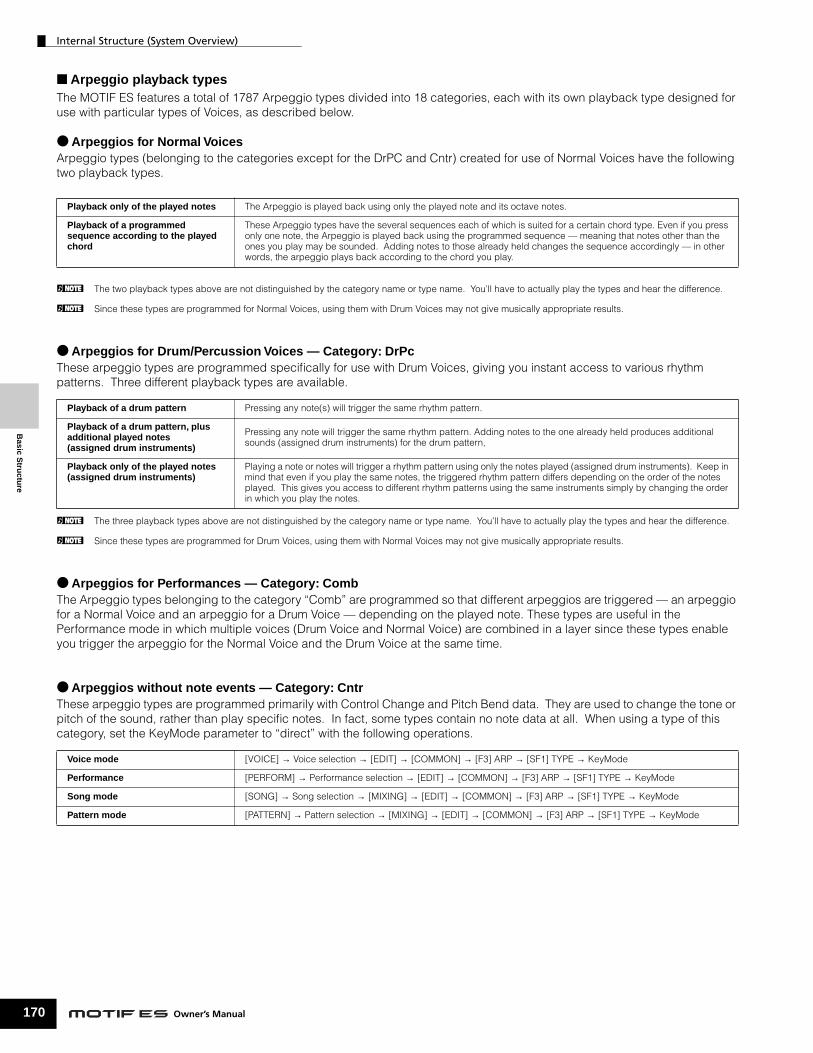
Internal Structure (System Overview)
170
Basic S
tructu
re
■ Arpeggio playback typesThe MOTIF ES features a total of 1787 Arpeggio types divided into 18 categories, each with its own playback type designed for use with particular types of Voices, as described below.
● Arpeggios for Normal VoicesArpeggio types (belonging to the categories except for the DrPC and Cntr) created for use of Normal Voices have the following two playback types.
n The two playback types above are not distinguished by the category name or type name. You’ll have to actually play the types and hear the difference.
n Since these types are programmed for Normal Voices, using them with Drum Voices may not give musically appropriate results.
● Arpeggios for Drum/Percussion Voices — Category: DrPcThese arpeggio types are programmed specifically for use with Drum Voices, giving you instant access to various rhythm patterns. Three different playback types are available.
n The three playback types above are not distinguished by the category name or type name. You’ll have to actually play the types and hear the difference.
n Since these types are programmed for Drum Voices, using them with Normal Voices may not give musically appropriate results.
● Arpeggios for Performances — Category: CombThe Arpeggio types belonging to the category “Comb” are programmed so that different arpeggios are triggered — an arpeggio for a Normal Voice and an arpeggio for a Drum Voice — depending on the played note. These types are useful in the Performance mode in which multiple voices (Drum Voice and Normal Voice) are combined in a layer since these types enable you trigger the arpeggio for the Normal Voice and the Drum Voice at the same time.
● Arpeggios without note events — Category: CntrThese arpeggio types are programmed primarily with Control Change and Pitch Bend data. They are used to change the tone or pitch of the sound, rather than play specific notes. In fact, some types contain no note data at all. When using a type of this category, set the KeyMode parameter to “direct” with the following operations.
Playback only of the played notes The Arpeggio is played back using only the played note and its octave notes.
Playback of a programmed sequence according to the played chord
These Arpeggio types have the several sequences each of which is suited for a certain chord type. Even if you press only one note, the Arpeggio is played back using the programmed sequence — meaning that notes other than the ones you play may be sounded. Adding notes to those already held changes the sequence accordingly — in other words, the arpeggio plays back according to the chord you play.
Playback of a drum pattern Pressing any note(s) will trigger the same rhythm pattern.
Playback of a drum pattern, plus additional played notes (assigned drum instruments)
Pressing any note will trigger the same rhythm pattern. Adding notes to the one already held produces additional sounds (assigned drum instruments) for the drum pattern,
Playback only of the played notes (assigned drum instruments)
Playing a note or notes will trigger a rhythm pattern using only the notes played (assigned drum instruments). Keep in mind that even if you play the same notes, the triggered rhythm pattern differs depending on the order of the notes played. This gives you access to different rhythm patterns using the same instruments simply by changing the order in which you play the notes.
Voice mode [VOICE] → Voice selection → [EDIT] → [COMMON] → [F3] ARP → [SF1] TYPE → KeyMode
Performance [PERFORM] → Performance selection → [EDIT] → [COMMON] → [F3] ARP → [SF1] TYPE → KeyMode
Song mode [SONG] → Song selection → [MIXING] → [EDIT] → [COMMON] → [F3] ARP → [SF1] TYPE → KeyMode
Pattern mode [PATTERN] → Pattern selection → [MIXING] → [EDIT] → [COMMON] → [F3] ARP → [SF1] TYPE → KeyMode
Owner’s Manual

Internal Structure (System Overview)
Bas
ic S
tru
ctu
re
■ Arpeggio related parametersThe Arpeggio related parameters can be set from the following displays, depending on the selected mode.
● Voice mode
n MIDI output parameters for Arpeggio playback are set for each Voice in the Voice mode. In the other modes, however, they can be set for each Performance, Song, and Pattern.
● Performance mode
● Song mode
n Arpeggio related parameters in the Song mode belong to the Mixing. Therefore, if desired, store them to internal memory (DRAM) in the Song Mixing Store mode and save them to the SmartMedia/USB storage device as Song data in the File mode.
● Pattern mode
n Arpeggio related parameters in the Pattern mode belong to the Mixing. Therefore, if desired, store them to internal memory (DRAM) in the Pattern Mixing Store mode and save them to the SmartMedia/USB storage device as Pattern data in the File mode.
Arpeggio type parameters called up when selecting a Voice [VOICE] → Voice selection → [F6] ARP Page 189
[VOICE] → Voice selection → [EDIT] → [COMMON] → [F3] ARP Page 191
Assigning Arpeggio types to the [SF1] - [SF5] buttons for each Voice [VOICE] → Voice selection → [F1] PLAY Page 188
MIDI output parameters for Arpeggio playback for all the Voices [VOICE] → [UTILITY] → [F3] VOICE → [SF3] ARP CH Page 262
Arpeggio type parameters called up when selecting a Performance (including MIDI output parameters for Arpeggio playback)
[PERFORM] → Performance selection → [F6] ARP Page 213
[PERFORM] → Performance selection → [EDIT] → [COMMON] → [F3] ARP Page 214
Assigning Arpeggio types to the [SF1] - [SF5] buttons for each Performance [PERFORM] → Performance selection → [F1] PLAY Page 212
Parameters about the Arpeggio type called up when selecting a Song (including MIDI output parameters for Arpeggio playback)
[SONG] → Song selection → [MIXING] → [EDIT] → [COMMON] → [F3] ARP Page 234
Assigning Arpeggio types to the [SF1] - [SF5] buttons for each Song [SONG] → Song selection → [F1] PLAY Page 221
[SONG] → Song selection → [● ] (Record) → [F3] ARP Page 223
Arpeggio type parameters in recording [SONG] → Song selection → [● ] (Record) → [F4] REC ARP Page 223
Parameters about the Arpeggio type called up when selecting a Pattern (including MIDI output parameters for Arpeggio playback)
[PATTERN] → Pattern selection → [MIXING] → [EDIT] → [COMMON] → [F3] ARP Page 248
Assigning Arpeggio types to the [SF1] - [SF5] buttons for each Pattern [PATTERN] → Pattern selection → [F1] Play Page 241
[PATTERN] → Pattern selection → [● ] (Record) → [F3] ARP Page 243
Arpeggio type parameters in recording [PATTERN] → Pattern selection → [● ] (Record) → [F4] REC ARP Page 243
171Owner’s Manual

Internal Structure (System Overview)
172
Basic S
tructu
re
Sampling Block
Sampling is a powerful function that lets you bring your own recorded sounds – voice, instrument, rhythm, special sound effects, etc. – into the system of this synthesizer, and play those sounds just as you would the Voices of the instrument.
In order to use the Sampling features of the instrument, you’ll need to install DIMM memory modules (sold separately) to the instrument.
n In addition to being able to record samples directly with the MOTIF ES, you can also import existing audio data (in WAV or AIFF file format) in the File mode. This lets you use audio you’ve recorded and edited on computer with the instrument.
40
127
D�2 A
�2 G
�2 F4
A /D INPUTLR
GAIN
OPTICAL DIGITAL
OUTINOUTIN
DAT CARD3.3V
Microphone, etc. CD, MD, etc.
USB connector
mLAN device(Data Rate S400)
A/D INPUT jacks OPTICAL IN connector or DIGITAL IN connector(when the optional AIEB2 has been installed)
mLAN connector (when the optional mLAN16E has been installed)
Optional DIMM (up to 1GB)
Velocity
Key number (Note number)
WaveformSample 1(Key bank)
Sample 2(Key bank)
Sample 4(Key bank)
Sample 3(Key bank)
Sample 5(Key bank)
USB
TO HOSTTO DEVICE
Sampling Source
Loading the WAV file/AIFF file from the [FILE] → [F3] LOAD display, setting the file type to “Waveform.”
Before sampling, connect the source to the appropriate connector.
SmartMedia/USB storage device
Load
Sampling Executing from the [INTEGRATED SAMPLING] → [F6] REC display in the Sampling mode
Sample (Wave)
Sampling DestinationBefore sampling, set the appropriate location for storing the sample (Waveform, User Voice) from the [INTEGRATED SAMPLING] → [F1] DEST display.
Waveform
User Voice Sample Voice(When executing the Sampling function in the Voice mode/Performance mode)
(When executing the Sampling function in the Song mode/Pattern mode)
Owner’s Manua
l
Internal Structure (System Overview)
Bas
ic S
tru
ctu
re
Data created by Sampling
Regardless of the mode, the raw Sampled data is the same, of course. However, various parameters are different, depending on the particular mode or settings. Briefly, here is an explanation of what kinds of data are created in the Sampling function.
● Sampling data common to all modes
Wave (Sample data)This is the raw audio data stored in this synthesizer’s internal memory when sampling.
Key BankThe note range and velocity range to which the Sample is assigned, is called the Key Bank.
WaveformThe group of Key Banks to which sample data is assigned is called the Waveform.
● Data created by sampling in the Voice/Performance mode
User VoiceBefore you can play the recorded/imported sample data (Waves), you’ll need to save them as User Voices, after which they can be selected and played from the keyboard or sequencer — the same as other Voices. Also, these User Voices can be assigned as Performance parts – just as with the Preset Voices.
● Data created by sampling in the Song/Pattern mode
Sample Voice
When sampling in the Song/Pattern mode, the recorded/imported sample data is automatically stored as a Sample Voice.Sample Voices can be assigned to the Mixing parts corresponding to the track which was assigned from the [INTEGRATED SAMPLING] → [F1] DEST display, and they can be sounded while Song/Pattern data is being played back. Sample Voices are original, dedicated Voices for the particular Song/Pattern that was selected when sampling. Because of this, you cannot take a Sample Voice belonging to one Song or Pattern and use it in another Song or Pattern.
n You cannot select Sample Voices in the Voice or Performance mode. (However, you CAN select the Wave of the Sample Voice in Voice Edit.)
Song or Pattern
SamplingTrack 1
Track 2
Track 3
Track 16
Specify the track.Record to create a Sample Voice.
Note DataWhen you set the Type to “Sample + note” from the [SONG] or [PATTERN] → [INTEGRATED SAMPLING] → [F2] SOURCE display and execute Sampling, a Sample Voice is created and the sampled wave is assigned to a specified note and recorded as simple MIDI sequence data to a specified track (as shown below).
Key Bank and Sequence dataWhen you set the Type to “Sample + seq” from the [SONG] or [PATTERN] → [INTEGRATED SAMPLING] → [F2] SOURCE display and execute Sampling, a Sample Voice is created and the sampled wave is “sliced” or divided into several component samples — and each is assigned to specific notes, with sequence data for playing the notes to recreate the sample. This is useful with rhythmic samples, giving you fine control over the playback, including tempo changes.
Sample
Assign the Sample to a specified key (note) to create a Sample Voice.
Sequence data
Sample
Slice the Sample and assign the sliced Sample to specified keys (notes) to create a Sample Voice.
Sequence data
173Owner’s Manual

Basic S
tructu
re
Internal Structure (System Overview)
174
Waveform and User Voices/Sample Voices
n When executing the Sampling in the Sampling mode entered from the
A B C P
001
002
003
004
005
006
007
008
009
010
1023
1024
001
002
003
004
005
128
40
127
D�2 A�2 G�2 F4
Velocity
WaveformSample 1(Key bank)
Sample 2(Key bank)
Sample 4(Key bank)
Sample 3(Key bank)
Sample 5(Key bank)
User Voice
Pattern 64
Pattern 02
Pattern 01
Pattern
Sample Voices (recorded to each track)
Sample Voices (recorded to each track)
16 sections
Track 2
Track 3
Track 1
Track 16
Track 2
Track 16
Track 1
Track 3
Sampling
When entering Sampling mode from Voice/Performance mode
Loading WAV/AIFF files
Waveform
Waveform(User 001 - 1024)
When entering File mode from Voice/Performance mode
Sampling
When entering Sampling mode from Pattern mode
Loading WAV/AIFF files
When entering File mode from Pattern mode
Sampling
When entering Sampling mode from Song mode
Loading WAV/AIFF files
When entering File mode from Song mode
Song 64
Song 02
Song 01
Voice mode/Performance mode, you can specify the Waveform number and User Voice number as a Destination (location to which the sampled wave is stored) beforehand. Likewise, you can specify the same parameters also when loading the WAV file/AIFF file in the File mode entered from the Voice mode/Performance mode.
n When executing the Sampling in the Sampling mode entered from the Song mode/Pattern mode, you can specify the track number as a Destination (location to which the sampled wave is stored) beforehand. Likewise, you can specify the same parameters also when loading the WAV file/AIFF file in the File mode entered from the Song mode/Pattern mode. When creating Waveforms, sampled audio waves are automatically stored starting from the lowest numbered available space.
n Up to 128 keybanks can be assigned to a single waveform. Up to a maximum of 4096 key banks can be created on the instrument.
Owner’s Manual
■ How to select and hear the WaveformYou can select and hear any of Waveforms from the following display in the Voice Edit mode.
If you set the Bank parameter to “usr wave,” you can select and hear the Waveform obtained by using the Sampling function or loading the WAV file/AIFF file. You can also select and hear the User Waveform from the following display in the Sampling mode.
[VOICE] → [EDIT] → Element selection → [F1] OSC → [SF1] WAVE
[INTEGRATED SAMPLING] → [EDIT] → [F1] KEY BANK

Internal Structure (System Overview)
Bas
ic S
tru
ctu
re
Trigger mode
The Trigger mode is a convenient feature in Sampling that lets you determine how sample recording is started — manually or automatically, based on the audio level.
■ Start recording manually
Regardless of the audio input signal level or the Song/Pattern playback status, sampling starts soon after you press the [F6] REC button in the Sampling Setup display. Sampling also starts regardless of the playback/stop status of the Song/Pattern.
■ Start recording when the input signal exceeds the Trigger Level
After pressing the [F6] REC button in the Sampling Setup display (in any mode), sampling starts as soon as a strong enough audio signal is received. The threshold for this audio-triggered start is called the Trigger Level (explained in the illustration below).
As you can see, the higher the Trigger Level setting, the louder the input audio needs to be in order to start sampling. On the other hand, if the Trigger Level is set too low, a soft noise may be enough to inadvertently start sampling.
[INTEGRATED SAMPLING] → [F6] REC → TriggerMode
[INTEGRATED SAMPLING] → [F6] REC → TriggerMode =manual
[INTEGRATED SAMPLING] → [F6] REC → TriggerMode =level
A B C D E
A B C D E
Level
Level
Sample recording starts here.
Sample recording starts here.
Recording trigger level.
Recording trigger level.
■ Start recording when the Song/Pattern playback reaches a specified point
After pressing the [F6] REC button in the Sampling Setup display, start and stop of sampling is linked to playback of the Song/Pattern.This setting is available only when the Song/Pattern mode and recording type (Rec Type) are set to “Slice + Seq” or “Sample + Note.”
[INTEGRATED SAMPLING] → [F6] REC → TriggerMode = meas
1 2 3 4 5 6 7 8
1 2 3 4 5 6 7 8
Song/Pattern
start
Sampling start Sampling stop
Punch In Punch Out
Wave data
175Owner’s Manual

Basic S
tructu
re
Internal Structure (System Overview)
176
Sample playback types
Samples can be set to play back in the following three different ways.
■ One Shot
When you press a note on the keyboard, the Sample plays from beginning to end just once. This type of playback is commonly used for drum and percussion sounds.
■ Loop
This is used primarily to create long continuous sounds, such as brass and strings, or instruments with naturally long decay, such as piano. An appropriate part of the sample near the end is looped to reproduce a long sustain or decay.When you play a note on the keyboard, the Sample plays from the start point to the end point. It then returns to the loop start point and plays to the end point again, and keeps doing this until you release the note. With musical instruments in general, the characteristic part of the sound (the “attack” section) is usually at the beginning, just after the start point. After this, the sound does not vary a great deal while the note is being held, and you can set the loop and end points at either end of this section. When playing back a Sample of an instrument that has been looped like this, the attack section of the sound is played back once and then the looped section is played back continuously until you release the note. Looping is also way of creating usable instrument sounds without using up too much memory.You can set each point in the Sampling mode. Since this synthesizer is capable of displaying the entire image of the sampled audio data in the LCD (zoom in and zoom out are available), you can edit the loop points visually – making sample editing accurate and easy.
[INTEGRATED SAMPLING] → [EDIT] → [F3] PARAM → PlayMode
[INTEGRATED SAMPLING] → [EDIT] → [F3] PARAM → PlayMode = oneshot
[INTEGRATED SAMPLING] → [EDIT] → [F3] PARAM → PlayMode = loop
Start PointKey on
End Point
Owner’s Manual
■ Reverse
When you press a note on the keyboard, the Sample plays from end to beginning just once. This is useful for creating reversed cymbal sounds and other special effects.
[INTEGRATED SAMPLING] → [EDIT] → [F3] PARAM → PlayMode = reverse
Start Point End Point
Sample Wave Loop Playback
Top Point
Start Point End Point

Internal Structure (System Overview)
Bas
ic S
tru
ctu
re
Effect Block
This block applies effects to the output of the tone generator block, processing and enhancing the sound using sophisticated DSP (digital signal processing) technology.
Effect structure
The effect processing of this synthesizer features the System Effects, Insertion Effects, Master Effect, Part EQ (Equalizer), and Master EQ (Equalizer).
■ System Effects (Reverb, Chorus)System Effects are applied to the overall sound, whether it be a Voice, an entire Performance, a Song, etc.With System effects, the sound of each Part is sent to the effect according to the effect Send Level for each Part. The processed sound (referred to as “wet”) is sent back to the mixer, according to the Return Level, and output – after being mixed with the unprocessed “dry” sound. This arrangement lets you prepare an optimum balance of the effect sound and the original sound of the Parts.
ReverbThe Reverb effects add a warm ambience to the sound, simulating the complex reflections of actual performance spaces, such as a concert hall or a small club. A total of 20 different Reverb types are available.
ChorusThe Chorus effects use various types of modulation processing, including flanger and phaser, to enhance the sound in a variety of ways. A total of 49 types are available, including reverb and delay effects.
n About the System Effect related display in each mode, see pages 179 and 180.
■ Insertion Effects A, BInsertion effects can be applied individually to each part. Insertion effects are mainly used to directly process a single part. The depth of the effect is adjusted by setting the dry/wet balance. Since an Insertion effect can only be applied to one particular part, it should be used for sounds you want to drastically change or for sounds that use an effect unintended for other sounds. You can also set the balance so that only the effect sound is heard, by setting Wet to 100%. This synthesizer features eight sets of Insertion effects (one set has A and B units). They can be applied to all parts of the Performance, and applied to eight parts (maximum) of the Song/Pattern. A total of 116 different Chorus types are available.
n In the Voice mode, only one set of the Insertion effects is available.
n For details on the displays related to the Insertion effects in each mode, see pages 179 and 180.
n Among the AUDIO IN parts, Insertion effects cannot be applied to the mLAN parts and AIEB2 parts.
■ Plug-in Insertion EffectsThis is a special effect system, only available when an effect-type Plug-in Board is installed. Plug-in Board effects are not available in the Voice mode.
n For details on the displays related to the Plug-in Insertion effects in each mode, see pages 179 and 180.
■ Master EffectThis block applies effects to the final stereo output signal of the entire sound. A total of 8 different Master Effect types are available.
n For details on the displays related to the Master effects in each mode, see pages 179 and 180.
EFFECT Buttons
Three EFFECT buttons on the panel let you switch each effect block on and off.
Press the [INSERTION] button below “BYPASS” so that the lamp lights to turn the Insertion effects off. You can specify which Insertion effects (only the internal Insertion effect, only the Plug-in Insertion effect, or both of them) are bypassed from the [UTILITY] → [F1] GENERAL → [SF3] EF BYPS display in the Utility mode. Press the [SYSTEM] button below “BYPASS” so that the lamp lights to turn the System effects off. You can specify which System effects (only the Reverb effect, only the Chorus effect, or both of them) are bypassed from the [UTILITY] → [F1] GENERAL → [SF3] EF BYPS display in the Utility mode. Press the [MASTER EFFECT] button so that the lamp lights to turn the Master effect on. Keep in mind that pressing and holding this button calls up the Master effect setup display in the current mode.
Controlling the Master effect by using the Knobs
When pressing the [ARP FX] button and the [EQ] button simultaneously (both lamps light), you can control the Knobs to adjust the Master effect related parameters specified in the [UTILITY] → [F4] CTL ASN → [SF5] MEF display of the Utility mode.
BYPASSINSERTION SYSTEM
MASTEREFFECT
EFFECT
177Owner’s Manual

Basic S
tructu
re
Internal Structure (System Overview)
178
■ Equalizer (EQ)Usually an equalizer is used to correct the sound output from amps or speakers to match the special character of the room, or to change the tonal character of the sound. The sound is divided into several frequency bands, and adjustments are made to the sound by raising or lowering the level of each band.By adjusting the sound according to the genre – classical music being more refined, pop music more crisp, and rock music more dynamic – you can draw out the special characteristics of the music and make your performance more enjoyable. Three separate EQ sections are available on the instrument: Element EQ, Part EQ, and Master EQ.
● Element EQ
The Element EQ is applied to each element of the Normal Voice and each key of the Drum Voice. You can specify which shape is used among the two shapes described below and set the related parameters.
Peaking typeThis type of EQ shape lets you attenuate/boost the signal at the specified Frequency setting.
Shelving typeThis type of EQ shape lets you attenuate/boost the signal at frequencies above or below the specified Frequency setting.
n In addition to the individual gain controls, there is also an overall level parameter that attenuates/boosts the entire frequency range.
[VOICE] → Voice selection → [EDIT] → Element selection/Key selection → [F6] EQ
–
+
0
Gain
Frequency
–
+
0
Gain Low Gain High Gain
Low Freq High Freq
Frequency
Owner’s Manual
● Part EQThis 3-band EQ is applied to each part of the Performance/Song/Pattern, The high band and low band are the shelving type. The middle band is the peaking type.
n The part EQ is not available in the Voice mode.
● Master EQMaster EQ is applied to the final (post-effect), overall sound of the instrument. In this EQ, all bands can be set to peaking, or the lowest and highest bands can be set to shelving (as shown below).
EQ for which all bands are set to peaking type
EQ for which LOW and HIGH are set to shelving type
–
+
0
LOW HIGHMID
Gain
3 bands
Q (frequency bandwidth)
Frequency
LOW HIGHHIGHMIDMIDLOWMID
–
+
0
Gain
3 bands
Q (frequency bandwidth)
Frequency
LOW HIGHHIGHMIDMIDLOWMID
–
+
0
Gain
5 bands
Q (frequency bandwidth)
Frequency

Bas
ic S
tru
ctu
re
Internal Structure (System Overview)
Effect connection in each mode
● In the Voice modeThe Effect parameters in the Voice mode are set for each Voice and the settings are stored to internal flash ROM as a User Voice. Please note that the Master Effect and Master EQ parameters are set for all the Voices in the Utility mode and stored to internal flash ROM as System settings by pressing the [STORE] button also in the Utility mode.
n The parallel connection is not available for Plug-in voices.
n The Plug-in Insertion effect (when the Effect Plug-in board has been installed) is not available in the Voice mode.
● In the Performance modeThe Effect parameters in the Performance mode are set for each Performance and the settings are stored to internal flash ROM as User data.
[VOICE] → Voice selection → [EDIT] → [COMMON] → [F6] EFFECT → [SF1] CONNECT
[VOICE] → [UTILITY] → [F3] VOICE → [SF2] MEF (for all Voices)
[VOICE] → [UTILITY] → [F3] VOICE → [SF1] MEQ (for all Voices)
[VOICE] → Voice selection → [EDIT] → [COMMON] → [F1] GENERAL → [SF3] MEQ OFS
You can set which Insertion system, A or B, is applied to each Element (or to each key when the Drum voice is selected). The Insertion effect can also be bypassed.
Tone Generator block
Element or KeyElement EQ
Reverb (REV), Chorus (CHO)
Send Level Return Level
You can select the Insertion connection from the three types shown below.
Insertion Effect
System Effect
Master Effect Master EQ Output
A
B
A to B
A
B
B to A
A
B
parallel
[PERFORM] → Performance selection → [EDIT] → [COMMON] → [F6] EFFECT → [SF1] CONNECT
The Insertion connection type depends on the setting of the Voice assigned to the selected part.
[PERFORM] → Performance selection → [EDIT] → Part selection → [F3] EQ
[PERFORM] → Performance selection → [EDIT] → [COMMON] → [F2] OUT/MEF → [SF1] OUT
Select the part to which the Plug-in Insertion effect is applied from Parts 1-4, Plug-in Parts 1-3, and the audio input Part in the following display. [PERFORM] → Performance selection → [EDIT] → [COMMON] → [F6] EFFECT → [SF1] INS SW
Among all of the audio input Parts, the Insertion effect can be applied only to the A/D Input Part.
[PERFORM] → Performance selection → [EDIT] → [COMMON] → [F2] OUT/MEF → [SF2] MEQ
[PERFORM] → Performance selection → [EDIT] → [COMMON] → [F1] GENERAL → [SF3] MEQ OFS
Part 1Part EQ
Insertion Effect(VCE INS)
Audio Input part
Plug-in Insertion Effect (PLG-EF)
When the PLG100-VHhas been installed
Tone Generatorblock
Part 1
[PERFORM] → Performance selection → [EDIT] → [COMMON] → [F2] OUT/MEF → [SF3] MEF
Master Effect Master EQ Output
*1
*2
*3
*4
*5
A
B
*2*3
*4
*5
*2
*1
Send Level Return Level
Reverb (REV), Chorus (CHO)System Effect
179Owner’s Manual

Internal Structure (System Overview)
180
Basic S
tructu
re
● In the Song mode/Pattern modeThe Effect parameters in the Song mode/Pattern mode are set for each Song/Pattern. The Effect settings are stored to internal DRAM in the Song Mixing mode/Pattern Mixing mode and saved to the SmartMedia/USB storage device in the File mode.
n The Insertion Effect, Plug-in Insertion Effect, and the System Effect cannot be applied to Parts 17-32 (using the Multi-part Plug-in board PLG100-XG).
n The Part EQ cannot be applied to parts of the Plug-in Board.
n The System Effects (Reverb, Chorus), the Master EQ, and the Master Effect are not applied to the sound output through the ASSIGNABLE OUTPUT jacks (including those of the AIEB2) or the mLAN connector of the mLAN16E board. (Only the Part EQ and the Insertion Effect are applied.)
Tone Generator block
[SONG] or [PATTERN] → Song/Pattern selection → [MIXING] → [EDIT] → [COMMON] → [F2] MEQ/MEF → [SF2] MEF
The Insertion effects can be applied to up to eight Parts, selectable from Parts 1-4, Plug-in Parts 1-3, and the A/D input Part in the following display. [SONG] or [PATTERN] → Song/Pattern selection → [MIXING] → [EDIT] → [COMMON] → [F6] EFFECT → [SF2] INS SWThe connection type depends on the setting of the Voice assigned to the selected part.
[SONG] or [PATTERN] → Song/Pattern selection → [MIXING] → [EDIT] → Part selection → [F3] EQ
Select the part to which the Plug-in Insertion effect is applied from Parts 1-4, Plug-in Parts 1-3, and the audio input Part.
Among all of the audio input Parts, the Insertion effect can be applied only to the A/D Input Part.
[SONG] or [PATTERN] → Song/Pattern selection → [F4] EF SEND
[SONG] or [PATTERN] → Song/Pattern selection → [MIXING] → [EDIT] → [COMMON] → [F2] MEQ/MEF → [SF1] MEQ
[SONG] or [PATTERN] → Song/Pattern selection → [MIXING] → [EDIT] → [COMMON] → [F1] GENERAL → [SF1] MEQ OFS
Part 17-32(When the Multi-part Plug-in Board
PLG100-XG has been installed)
*1
*2
*3
*4
*5
*6
A
B
*1
*2
*3
*5
*4*6
*1
[SONG] or [PATTERN] → Song/Pattern selection → [MIXING] → [EDIT] → [COMMON] → [F6] EFFECT → [SF1] CONNECT
Part 1-16 Insertion Effects(VCE INS)
Tone Generator block Part 1
Reverb (REV), Chorus (CHO)System Effects
Part 1Part EQ
Plug-in Part 1-3(When the Single part
Plug-in board has been installed)
Audio Input part
Plug-in Insertion Effect (PLG-EF)
When the PLG100-VH has been installed
Send Level Return Level
Master Effect Master EQ Output
Owner’s Manual

About MIDI
Bas
ic S
tru
ctu
re
About MIDIMIDI (Musical Instrument Digital Interface) is a standard which allows electronic musical instruments to communicate with each other, by sending and receiving compatible Note, Control Change, Program Change and various other types of MIDI data, or messages.This synthesizer can control other MIDI devices by transmitting note related data and various types of controller data. It can also be controlled by incoming MIDI messages which automatically determine the tone generator mode, select MIDI channels, voices and effects, change parameter values, and of course play the voices specified for the various Parts.
Many MIDI messages are expressed in hexadecimal or binary numbers. Hexadecimal numbers may include the letter “H” as a suffix. The letter “n” indicates a certain whole number.The chart below lists the corresponding decimal number for each hexadecimal/binary number.
MIDI channels
MIDI performance data is assigned to one of sixteen MIDI channels. Using these channels, 1 - 16, the performance data for sixteen different instrument parts can be simultaneously sent over one MIDI cable. Think of the MIDI channels as TV channels. Each TV station transmits its broadcasts over a specific channel.Your home TV set receives many different programs simultaneously from several TV stations and you select the appropriate channel to watch the desired program.
MIDI operates on the same basic principle.The transmitting instrument sends MIDI data on a specific MIDI channel (MIDI Transmit Channel) via a single MIDI cable to the receiving instrument. If the receiving instrument’s MIDI channel (MIDI Receive Channel) matches the Transmit Channel, the receiving instrument will sound according to the data sent by the transmitting instrument. For information on how to set the MIDI transmit channel and the MIDI receive channel, see page 35.
MIDI data is assigned to one of sixteen channels. However, we can overcome the sixteen-channel limit by using separate MIDI “ports,” each supporting sixteen channels. For details, see page 38.
MIDI Messages Transmitted/Recognized by this synthesizer
MIDI messages can be divided into two groups: Channel messages and System messages. Below is an explanation of the various types of MIDI messages which this synthesizer can recognize/transmit. The messages transmitted/recognized by this synthesizer are shown in the MIDI Data Format and MIDI Implementation Chart of the separate Data List.
n This synthesizer’s tone generator and sequencer blocks handle different MIDI events. These are listed separately in the MIDI Data Format as well as in the MIDI Implementation Chart.
1
Weather Report
News
2
2
News
MIDI Transmit channel 2 MIDI Receive channel 2
MIDIcable
181Owner’s Manual

Basic S
tructu
re
About MIDI
182
CHANNEL MESSAGES
Channel messages contain data related to the performance on the keyboard for the specific channel.
■ Note On/Note Off (Key On/Key Off)Messages which are generated when the keyboard is played.Reception note range = C-2 (0) - G8 (127), C3 = 60 Velocity range = 1 - 127 (Only the Note On velocity is received)Note On: Generated when a key is pressed.Note Off: Generated when a key is released.Each message includes a specific note number which corresponds to the key which is pressed, plus a velocity value based on how hard the key is struck.
■ Control ChangeControl Change messages let you select a voice bank, control volume, panning, modulation, portamento time, brightness and various other controller parameters, through specific Control Change numbers which correspond to each of the various parameters.
Bank Select MSB (Control #000)Bank Select LSB (Control #032)Messages which select variation voice bank numbers by combining and sending the MSB and LSB from anexternal device. The functions of MSB and LSB messages differ depending on the tone generator mode. MSB numbers select voice type (Normal Voice or Drum Voice), and LSB numbers select voice banks.(For more information about Banks and Programs, see Voice List in the separate Data List.)A new bank selection will not become effective until the next Program Change message is received.
Modulation (Control #001)Messages which control vibrato depth using the Modulation Wheel.Setting the value to 127 produces maximum vibrato and 0 results in vibrato off.
Portamento Time (Control #005)Messages which control the duration of portamento, or a continuous pitch glide between successively played notes.When the parameter Portamento Switch (Control #065) is set to on, the value set here can adjust the speed of pitch change. Setting the value to 127 produces maximum portamento time and 0 results in minimum portamento time.
Owner’s Manual
Data Entry MSB (Control #006)Data Entry LSB (Control #038)Messages which set the value for the parameter specified by RPN MSB/LSB (page 183) and NRPN MSB/LSB (page 183). Parameter value is determined by combining the MSB and LSB.
Main Volume (Control #007)Messages which control the volume of each Part.Setting the value to 127 produces maximum volume and 0 results in volume off.
Pan (Control #010)Messages which control the stereo panning position of each Part (for stereo output).Setting the value to 127 positions the sound to the far right and 0 positions the sound to the far left.
Expression (Control #011)Messages which control intonation expression of each Part during performance.Setting the value to 127 produces maximum volume and 0 results in volume off.
Hold1 (Control #064)Messages which control sustain on/off.Setting the value between 64 - 127 turns the sustain on, between 0 - 63 turns the sustain off.
Portamento Switch (Control #065)Messages which control portamento on/off.Setting the value between 64 -127 turns the portamento on, between 0 - 63 turns the portamento off.
Sostenuto (Control #066)Messages which control sostenuto on/off.Holding specific notes and then pressing and holding the sostenuto pedal will sustain those notes as you play subsequent notes, until the pedal is released.Setting the value between 64 -127 turns the sostenuto on, between 0 - 63 turns the sostenuto off.
Harmonic Content (Control #071)Messages which adjust the filter resonance set for each Part.The value set here is an offset value which will be added to or subtracted from the voice data. Higher values will result in a more characteristic, resonant sound. Depending on the voice, the effective range may be narrower than the range available for adjustment.

About MIDI
Bas
ic S
tru
ctu
re
Release Time (Control #072)Messages which adjust the AEG release time set for each Part.The value set here is an offset value which will be added to or subtracted from the voice data.
Attack Time (Control #073)Messages which adjust the AEG attack time set for each Part.The value set here is an offset value which will be added to or subtracted from the voice data.
Brightness (Control #074)Messages which adjust the filter cutoff frequency set for each Part. The value set here is an offset value which will be added to or subtracted from the voice data. Lower values result in a softer sound.Depending on the voice, the effective range may be narrower than the range available for adjustment.
Decay Time (Control #075)Messages which adjust the AEG decay time set for each Part. The value set here is an offset value which will be added to or subtracted from the voice data.
Effect1 Depth (Reverb Send Level) (Control #091)Messages which adjust the send level for the Reverb effect.
Effect3 Depth (Chorus Send Level) (Control #093)Messages which adjust the send level for the Chorus effect.
Data Increment (Control #096)Decrement (Control #097) for RPNMessages which increase or decrease the MSB value of pitch bend sensitivity, fine tune, or coarse tune in steps of 1. You will need to assign one of those parameters using the RPN in the external device in advance. The data byte is ignored. When the maximum value or minimum value is reached, the value will not be incremented or decremented further. (Incrementing the fine tune will not cause the coarse tune to be incremented.)
NRPN (Non-Registered Parameter Number)LSB (Control #098) (Plug-in Board only)NRPN (Non-Registered Parameter Number)MSB (Control #099) (Plug-in Board only)Messages which adjust a voice’s vibrato, filter, EG, drum setup or other parameter settings.First send the NRPN MSB and NRPN LSB to specify the parameter which is to be controlled. Then use Data Entry (page 182) to set the value of the specified parameter.Note that once the NRPN has been set for a channel, subsequent data entry will be recognized as the same NRPN’s value change. Therefore, after you use the NRPN, you should set a Null (7FH, 7FH) value to avoid unexpected results.For details, refer to the owner’s manual of the relevant Plug-in Board.
RPN (Registered Parameter Number) LSB (Control #100)RPN (Registered Parameter Number) MSB (Control #101)Messages which offset, or add or subtract values from a Part’s pitch bend sensitivity, tuning, or other parameter settings. First send the RPN MSB and RPN LSB to specify the parameter which is to be controlled. Then use Data Increment/Decrement (page 183) to set the value of the specified parameter. Note that once the RPN has been set for a channel, subsequent data entry will be recognized as the same RPN’s value change. Therefore after you use the RPN, you should set a Null (7FH, 7FH) value to avoid unexpected results.The following RPN numbers can be received.
■ Channel Mode MessagesThe following Channel Mode Messages can be received.
All Sounds Off (Control #120)Clears all sounds currently sounding on the specified channel. However, the status of channel messages such as Note On and Hold On is maintained.
Reset All Controllers (Control #121)The values of the following controllers will be reset to the defaults.
All Notes Off (Control #123)Clears all notes currently on for the specified channel.However, if Hold1 or Sostenuto is on, notes will continue sounding until these are turned off.
RPN MSB RPN LSB PARAMETER
00 00 Pitch Bend Sensitivity
00 01 Fine Tune
00 02 Coarse Tune
7F 7F Null
2nd BYTE 3rd BYTE MESSAGE
120 0 All Sounds Off
121 0 Reset All Controllers
123 0 All Notes Off
126 0 - 16 Mono
127 0 Poly
CONTROLLER VALUE
Pitch Bend Change 0 (center)
Aftertouch 0 (off)
Polyphonic Aftertouch 0 (off)
Modulation 0 (off)
Expression 127 (max)
Hold1 0 (off)
Portamento 0 (off)
Sostenuto 0 (off)
Soft Pedal 0 (off)
Portamento Control Cancels the Portamento source key number
RPN Number not specified; internal data will not change
NRPN Number not specified; internal data will not change
183Owner’s Manual

Basic S
tructu
re
About MIDI
184
Mono (Control #126)Performs the same function as when an All Sounds Off message is received, and if the 3rd byte (mono number) is in the range of 0 - 16, it sets the corresponding channel to Mono Mode (Mode 4: m = 1).
Poly (Control #127)Performs the same function as when an All Sounds Off message is received, and sets the corresponding channel to Poly Mode.
■ Program ChangeMessages that determine which voice to select for each Part. With a combination of Bank Select, you can select not only basic voice numbers, but also variation voice bank numbers. For a list of the Voices, see the separate Data List.
■ Pitch BendPitch Bend messages are continuous controller messages that allow the pitch of designated notes to be raised or lowered by a specified amount over a specified duration.
■ Channel AftertouchMessages which let you control the sounds by the pressure you apply to the keys after the initial striking of the keys, over the entire channel.This synthesizer does not transmit this data from the keyboard; however, this synthesizer does properly respond to this data when received from an external device.
■ Polyphonic AftertouchMessages which let you control the sounds by the pressure you apply to the keys after the initial striking of the keys, for each individual key. This synthesizer does not transmit this data from the keyboard; however, the data is transmitted from the internal sequencer.
SYSTEM MESSAGES
System messages are the data related to the overall system of the device.
■ System Exclusive MessagesSystem Exclusive messages control various functions of this synthesizer, including master volume and master tuning, tone generator mode, effect type and various other parameters.
General MIDI (GM) System On (Song mode/Pattern only)When “General MIDI system on” is received, the MOTIF ES will receive the MIDI messages which are compatible with GM System Level 1, and consequently will not receive NRPN and Bank Select messages.
F0 7E 7F 09 01 F7 (Hexadecimal)
n Make sure that the interval between this message and the first note data of the song is at least a quarter note or greater in length.
Owner’s Manual
Master VolumeWhen received, the Volume MSB will be effective for the System Parameter.
F0 7F 7F 04 01 ll mm F7 (Hexadecimal)* mm (MSB) = appropriate volume value, ll (LSB) = ignored
■ System Realtime MessagesThese messages control the sequencer, that is to say Song and Pattern.
Active Sensing (FEH)Once FEH (Active Sensing) has been received, if no MIDI data is subsequently received for longer than an interval of approximately 300 msec, the MOTIF ES will perform the same function as when All Sounds Off, All Notes Off, and Reset All Controllers messages are received, and will then return to a status in which FEH is not monitored
Timing Clock (F8H)This message is transmitted with a fixed interval (24 times per 1/4 note) to synchronize connected MIDI instruments. You can select whether the sequencer block uses the internal Timing Clock, or external Timing Clock messages received via MIDI IN by setting the MIDI Sync parameter: [UTILITY] → [F5] MIDI → [SF3] SYNC → MIDI Sync.
Start (FAH)This message lets the MIDI sequence data start playing back from the beginning. This message will be transmitted when pressing the [F] (Play) button at the top of the Song or Pattern.
Continue (FBH)This message lets the MIDI sequence data start playing back from the current song position. This message will be transmitted when pressing the [F] (Play) button at the middle of the Song or Pattern.
Stop (FCH)This message causes MIDI sequence data (song) to stop playing back. This message will be transmitted when pressing the [■ ] (Stop) button during playback.
n You can select whether this synthesizer will transmit Timing Clock, Start, Continue, and Stop messages by setting the SeqCtrl parameter: [UTILITY] → [F5] MIDI → [SF3] SYNC → SeqCtrl.
■ System Common MessageSystem Common messages also control the sequencer, including Song Select and Song Position Pointer messages.

Bas
ic S
tru
ctu
re
Internal Memory and File Management
Internal Memory and File ManagementAs you use the MOTIF ES, you’ll create many different kinds of data, including Voices, Performances, Songs, and Patterns. This section describes how to maintain the various types of data and use the memory devices/media for storing them.
Maintaining data
You can maintain the data you’ve created via the following three methods.
● StoreThis is a process of transferring or saving the created data of this synthesizer to a dedicated location (User Memory) in the internal memory. Each type of data can be stored with the following operations.
* Please note that pressing the [STORE] in the Utility mode starts the Store operation of the System settings immediately.
Since Song Mixing, Pattern Mixing, and Mixing Voice data is stored to DRAM (page 187), all such data is lost when turning off the power — even if the data has been stored with the operations above. Make sure to save this data to the SmartMedia/USB storage device in the File mode after storing.
Never attempt to turn off the power while data (e.g., Voice) is being written to Flash ROM (while an “Executing...” or “Please keep power on” message is shown). Turning the power off in this state may cause the system to freeze (due to corruption of data in the Flash ROM) and prevent normal startup the next time the power is turned on, as well as resulting in the loss of all user data.
This is a process of transferring or saving the created data of this synthesizer to an external memory device (SmartMedia/USB storage device). This process can be done in the File mode. The Save operation can be done via various methods, such as saving all data as a single file or saving a specified type of data (e.g., only Voices) as a single file. For details, see Memory Structure (page 186) and Reference (page 188). The saved data as files can be recalled by loading them in the File mode.
● Bulk DumpThis function lets you save the data in the Edit buffer (DRAM) or Flash ROM by transmitting it as Bulk data (system exclusive message) to an external MIDI instrument or sequence software on a computer. This can be done with the following operations.
n Mixing Voice data cannot be transmitted as Bulk data via panel operations.
n User Arpeggio data and some of the System settings are not handled as Bulk data.
n The data in the User Memory of Flash ROM can be transmitted to an external MIDI instrument or computer upon reception of a bulk request message. For details about the bulk request message and bulk dump format, see the separate Data List.
Voice and Plug-in Voice data can be transmitted to a computer for editing with the Voice Editor software (on the included CD-ROM). The edited Voice data can then be transmitted back to the instrument in banks as bulk data. Similarly, Voice data created in the Voice Edit mode can be sent to the computer in banks as bulk data.
Song Mixing and Pattern Mixing data can also be transmitted to a computer for editing, using the Multi Part Editor software (on the included CD-ROM). The edited Mixing data can then be transmitted back to the instrument as bulk data. Mixing data created in the Song Mixing Edit and Pattern Mixing modes can also be sent to the computer in banks as bulk data.
Voice [VOICE] → Voice selection → [STORE] Page 85
Performance [PERFORM] → Performance selection → [STORE] Page 91
Song Mixing [SONG] → Song selection → [MIXING] → [STORE] Page 131
Pattern Mixing [PATTERN] → Pattern selection → [MIXING] → [STORE] Page 131
Mixing Voice [SONG] or [PATTERN] → Song/Pattern selection → [MIXING] → [F5] VCE ED → [STORE] Page 106
Master [MASTER] → Master selection → [STORE] Page 137
System settings [UTILITY] → [STORE] * Page 260
● Save [FILE] → [F2] SAVE
Voice [VOICE] → Voice selection → [JOB] → [F4] BULK
Performance [PERFORM] → Performance selection → [JOB] → [F4] BULK
Song Mixing [SONG] → Song selection → [MIXING] → [JOB] → [F4] BULK
Pattern Mixing [PATTERN] → Pattern selection → [MIXING] → [JOB] → [F4] BULK
Master [MASTER] → Master selection → [JOB] → [F4] BULK
CAUTION
CAUTION
185Owner’s Manual

Internal Memory and File Management
186
Basic S
tructu
re
Memory Structure
This diagram details the relationship among the functions of the MOTIF ES and the internal memory and SmartMedia/USB storage device.
*1 For details on the Bulk Dump, Save, and Store operations, see page 185.*2 Only the currently edited data can be transmitted as Bulk data. Note that the Mixing Voice cannot be transmitted as Bulk data. *3 The Mixing settings can be stored/recalled as a template in the Song Mixing Job mode/Pattern Mixing Job mode. *4 You can convert the MIDI sequence data recorded in the Song Record mode/Pattern Record mode to Arpeggio data. This can be executed with the following
operations: • [SONG] → [JOB] → [F5] TRACK → 07: Put Track to Arp • [PATTERN] → [JOB] → [F5] TRACK → 06: Track to Arp*5 In order to create a Waveform by sampling or importing an audio file, optional DIMM modules must be installed.
Sequence software
Voice Editor in the included CD-ROM
Multi Part Editor in the included CD-ROM
MIDI instrument or computer
SmartMedia/USB storage device
*4
*3
*3
*5
*2
Excluding Master and Utility settings
Recall BufferCompare Buffer
(DRAM)• Voice• Plug-in Voice• Preset Phrase (Pattern)• Preset Arpeggio• Demo
Preset Data (ROM)
Edit Buffer(DRAM)
User Memory
Flash ROM
Bulk Dump *1
Store *1
Store *1
Sto
re *
1
Bulk Dum
p *1
Internal Memory
• Voice Edit • User Voice (Normal, Drum) File extensions “.W7V” and “.W7E”
• File extensions “.WAV” and “.AIF”• A5000/4000/3000 data• AKAI format data
File extensions “.W7G”
File extensions “.W7A”(including all the data on the User Memory)
File extensions “.MID”
File extensions “.W7S”
File extensions “.W7P”
File extensions “.W7W”
• File extensions “.WAV” and “.AIF”• A5000/4000/3000 data• SU700 data• AKAI format data
File extensions “.W2B”
Internal data communication
Data communication between this synthesizer and the external device
• Mixing Voice Edit
• Plug-in Voice Edit
• Master Edit
• Utility settings
• Pattern Mixing Edit
• Song Mixing Edit
• Pattern Record
• System settings (Utility settings + Mixing Template)
• Pattern Patch
• Pattern Chain
• Sampling • Waveform
• Song Record
• Song Chain
• Phrase
• Pattern
• Pattern Chain
• Song
• Song Chain
• Performance Edit
• User Plug-in Voice
• User Master
• User Arpeggio
• User Performance
Editing the Board Voice (page 76) using the software Plug-in Board Editor supplied with each Plug-in Board
Computer
DRAM
• Plug-in All Bulk
Plug-in board (DRAM)
Lo
ad/S
ave
(exe
cute
d in
th
e F
ile m
od
e) *
1
Owner’s Manual

Bas
ic S
tru
ctu
re
Internal Memory and File Management
Internal Memory
Below are explanations of the basic terms used in the Memory Structure illustration on the previous page.
● Flash ROMROM (Read Only Memory) is memory designed specifically for reading out of data, and as such data cannot be written to it. Unlike conventional ROM, Flash ROM can be overwritten – allowing you to store your own original data. The contents of Flash ROM are maintained even when the power is turned off.
● DRAMRAM (Random Access Memory) is memory designed specifically for data writing and data reading operations. There are two different kinds of RAM, depending on the condition for storing the data: SRAM (Static RAM) and DRAM (Dynamic RAM). The created data stored on DRAM is lost when the power is turned off. Because of this, you should always store any data residing in DRAM to the SmartMedia/USB storage device before turning off the power.
● DIMMDIMM modules must be installed in order to use the Sampling function or to load audio data (Waveform/WAV file/AIFF file) to the instrument. As with DRAM described above, the created data stored on DIMM is lost when the power is turned off. Because of this, you should always store any data residing in DIMM to the SmartMedia/USB storage device before turning off the power.
● Edit Buffer and User MemoryThe edit buffer is the memory location for edited data of these types: Voice, Performance, Master, Song Mixing, and Pattern Mixing. Data edited in this location will be stored to the User Memory.If you select another Voice, Performance, Master, Song, or Pattern, the entire contents of the edit buffer will be rewritten with the newly selected Voice/Performance/Master/Song Mixing/Pattern Mixing data. Make sure to store any important data before selecting another Voice, etc.
● Edit Buffer and Recall BufferIf you’ve selected another Voice/Performance/Song/Pattern without storing the one you were editing, you can recall your original edits, since the edit buffer’s contents are stored in backup memory.
n Keep in mind that the recall buffer is not available in the Master Edit mode.
187Owner’s Manual

Reference Vo
ice Mo
de
Voice Play mode
188
Voice mode■ Creating Voices — basic procedureYou can create and edit your original Voices by setting various parameters in both the Voice Play mode and Voice Edit mode, while the Voice Job mode provides some basic parameter-related tools, such as Initialize and Copy. Once you’ve edited a Voice, you can store it to a User Bank in internal memory (Flash ROM) and save all edited Voices to a SmartMedia/USB storage device in the File mode.
The Voice Play mode lets you perform a variety of general editing operations on the selected voice. For more detailed and comprehensive editing operations, use the Voice Edit mode.
n In the Voice Play mode and Voice Edit mode, you can set the parameters for each Voice. The parameters for all the Voices such as Master EQ and Master Effect can be set from the [UTILITY] → [F3] VOICE display in the Utility mode.
n The parameters that have the same name in the Voice Play mode and in the Voice Edit mode have the same functions and settings.
n When a Plug-in voice is selected, certain parameters are not available for editing, even if they’re described here.
Reference
Voice Play mode [VOICE] → Voice selection
[F1] PLAY
TCH (Transmit Channel) Indicates the Keyboard MIDI transmit channel.You can change the Keyboard MIDI transmit channel by pressing the [TRACK SELECT] button so that its indicator lights and pressing any of the NUMBER [1] - [16] buttons. The Keyboard MIDI transmit channel can be changed also with the following operation: [UTILITY] → [F5] MIDI → [SF1] CH → KBDTransCh.
OCT (Octave) Indicates Keyboard Octave setting set via the [OCTAVE] buttons. This can be changed also with the following operation: [UTILITY] → [F1] GENERAL → [SF2] KBD → Octave.
ASA (ASSIGN A), ASB (ASSIGN B)
Indicates the functions assigned to the respective Knobs (printed “ASSIGN A” and “ASSIGN B”) when the lamps of both the [PAN/SEND] and [TONE] buttons are turned on. The functions are assigned with the following operation: [UTILITY] → [F4] CTL ASN → [SF2] ASSIGN.
n TCH (Transmit Channel), OCT (Octave), ASA (ASSIGN A), and ASB (ASSIGN B) settings do not belong to each Voice. Because of this, these are not stored as an individual Voice in the Voice Store mode (page 208).
AS1 (ASSIGN 1), AS2 (ASSIGN 2)
Indicates the functions assigned to the respective Knobs (printed “ASSIGN 1” and “ASSIGN 2”) when the lamps of both the [PAN/SEND] and [TONE] buttons are turned on. The functions are assigned by setting the Voice Edit common parameters with the following operation: [VOICE] → [EDIT] → [COMMON] → [F4] CTL SET.
[SF1] ARP1 (Arpeggio 1) - [SF5] ARP5 (Arpeggio 5)
You can register the desired Arpeggio types to these buttons and call them up any time during your keyboard performance. Refer to page 66 in the Quick Guide section.
[F2] BANK
This display is available only when a Plug-in Board has been installed and a Voice of the Plug-in Board is selected. From this display you can select the particular bank on the Plug-in board, and determine whether you will be using a Plug-in voice or a “Board” voice. Board voices are unprocessed, unaltered voices of the Plug-in board – the “raw material” for Plug-in voices. Plug-in voices are edited Board voices – voices that have been specially programmed and processed for optimum use with this synthesizer. For more details, see page 74.Settings: The following selections are available, for example, when a Plug-in voice using the Plug-in board installed to slot 1 is selected: PLG1USR (User Plug-in voice), PLGPRE1 (Preset
Plug-in voice), 032/000 ... (Indicates the Bank Select MSB/LSB of the Board voice. These values differ depending on the installed Plug-in board.)
[F3] EFFECT
Pressing the [F3] EFFECT button in the Voice Play mode calls up the same EFFECT display in the Voice Edit mode ([VOICE] → [EDIT] → [COMMON] → [F6] EFFECT). From this display, you can set the effect related parameters for the current Voice. See page 194.
[F4] PORTA (Portamento)
From this display you can select monophonic or polyphonic playback and set the Portamento parameters.Portamento is used to create a smooth transition in pitch from the first note played on the keyboard to the next.
Mono/Poly Determines whether the Voice is played back monophonically (single notes only) or polyphonically (multiple simultaneous notes).Settings: mono, poly
n When pressing the second note while holding the first note with the PortaSw set to on and the Mono/Poly set to on, the second note sound starts succeeding the transition of the first note, or the second note starts not from the EG (AEG/PEG/FEG) start point but from the EG (AEG/PEG/FEG) point the first note reaches. This realizes the legato performance. This legato degree can be set with the following operation: [VOICE] → [EDIT] → [COMMON] → [F1] GENERAL → [SF4] PORTA → LegatoSlope (page 190).
PortaSw (Portamento Switch) Determines whether Portamento is applied to the current Voice or not.Settings: off, on
Owner’s Manual

Ref
eren
ce V
oic
e M
od
e
Voice Edit mode Normal Voice Edit Common Edit
There are three kinds of Voices: Normal Voices, Drum Voices and Plug-in Voices (if a Plug-in board has been installed). The following section shows how to edit the different types of voices and explains the parameters available. Note that available parameters to be edited differ depending on the Voice types (Normal Voice, Drum Voice, Plug-in Voice).
Normal Voice EditWhen a Normal Voice is selected, the Voice Edit parameters are divided into Common Edit (parameters common to all four Elements), and Element Edit (parameters of individual Elements).
These parameters are for making global (or common) edits to all four Elements of the selected Normal Voice.
PortaTime (Portamento Time) Determines the pitch transition time. Higher values result in longer transition times.Settings: 0 ~ 127
PortaMode (Portamento Mode) Determines the Portamento mode. The behavior of the Portamento varies depending on whether Mono/Poly is set to “mono” or “poly.”Settings: fingered, fulltimefingered ........... Portamento is only applied when you play legato (playing the next note before releasing the previous one). fulltime ............. Portamento is always applied.
[F5] EG (Envelope Generator)
This display contains the basic EG settings, both volume and filter, for the voice, as well as the filter’s cutoff frequency and resonance settings. The settings made here are applied as offsets to the AEG and FEG settings in the Voice Edit mode.The full names of the available parameters are shown in the chart below, as they appear in the display.
Settings: -64 ~ 0 ~ +63 (except --- above)
[F6] ARP (Arpeggio)
This display contains the basic settings for Arpeggio playback, including Type and Tempo. About the [SF1] - [SF5] buttons, see the explanation of the [F1] PLAY display.
Bank, Ctgr (Category), Type
These three parameters determine the Arpeggio Type. The three-letter prefix number before the Type name indicates the number within the selected Category.Settings: Refer to the separate Data List.
Tempo Determines the Arpeggio Tempo. When MIDI Sync ([UTILITY] → [F5] MIDI → [SF3] SYNC → MIDI Sync) is set to “MIDI,” “MIDI” is displayed here and cannot be set.Settings: 1 ~ 300
VelLimit (Velocity Limit) Determines the lowest and highest velocity which can trigger the Arpeggio playback. The Arpeggio plays when you play notes at velocities within in this range.Settings: 1 ~ 127
n Keys played outside the set limit sound normally without any Arpeggio.
Switch Determines whether Arpeggio is on or off. You can also turn Arpeggio on/off from the front panel with the [ARPEGGIO ON/OFF] button.Settings: off, on
Hold Determines whether the Arpeggio playback is “held” or not. When this is set to “on,” the Arpeggio cycles automatically, even if you release your fingers from the keys, and it continues to cycle until the next key is pressed.Settings: sync-off (see below), off, onsync-off............ When set to “sync-off,” the Arpeggio playback continues to run silently, even when you release the keys. Pressing any
key turns the Arpeggio playback on again. In other words, you can use the key to “un-mute” or “mute” (not start or stop) the Arpeggio playback by, respectively, holding it down or releasing it.
Voice Edit mode [VOICE] → Voice selection → [EDIT]
Common Edit [VOICE] → Normal Voice selection → [EDIT] → [COMMON]
[F1] GENERAL
[SF1] NAME From this display you can assign the category (sub and main) of the selected voice, and create a name for the voice. The voice name can contain up to 10 characters. For detailed instructions on naming a voice, see “Basic Operation” on page 53.
ATK DCY SUS REL DEPTH CUTOFF RESO
AEGAttack time Decay time
Sustain levelRelease Time
--- --- ---
FEG --- Depth Cutoff frequency Resonance
189Owner’s Manual

Reference Vo
ice Mo
de
Voice Edit mode Normal Voice Edit Common Edit
190
[SF2] PLY MODE (Play mode) From this display you can make various settings for the tone generator of this synthesizer, and assign different Micro Tuning settings.
Mono/Poly Determines whether the Voice is played back monophonically (single notes only) or polyphonically multiple simultaneous notes).Settings: mono, poly
KeyAsgnMode (Key Assign Mode)
When this is set to “single,” double playback of the same note is prevented. This is useful when two or more instances of the same note are received nearly simultaneously, or without a corresponding note off message. To allow playback of each instance of the same note, set this to “multi.”Settings: single, multi
M. TuningNo. (Micro Tuning Number)
Determines the tuning system for the voice. Normally, this should be set to 00 (Equal temperament); however additional tuning systems are available for a variety of tuning applications and effects. Settings: See the Micro Tuning List on page 209.
M. TuningRoot (Micro Tuning Root)
Determines the root note of the Micro Tuning set above. Settings: C ~ B
[SF3] MEQ OFS (Master EQ Offset)
From this display you can adjust the master (global) EQ settings for the entire Voice. The settings made here are applied as offsets to the EQ settings (with the exception of “MID”) from the Utility mode, with the following operation: [VOICE] → [UTILITY] → [F3] VOICE → [SF1] MEQ. You can edit these parameters by using the Knobs.Settings: -64 ~ 0 ~ +63
[SF4] PORTA (Portamento) This display allows you to set the Portamento related parameters. Portamento is used to create a smooth transition in pitch from the first note played on the keyboard to the next.
Switch Determines whether Portamento is applied to your keyboard performance using the current Voice or not. Settings: off, on
Time Determines the pitch transition time. Higher values result in a longer pitch change time, when Time Mode below is set to “Time.”Settings: 0 ~ 127
Mode Determines how the Portamento is applied to your keyboard performance. Settings: fingered, fulltime fingered............Portamento is only applied when you play legato (playing the next note before releasing the previous one).fulltime..............Portamento is always applied.
TimeMode This determines how the pitch changes in time. Settings: rate1, time1, rate2, time2rate1.................Pitch changes at the specified rate. time1 ................Pitch changes in the specified time. rate2.................Pitch changes at the specified rate within a octave. time2 ................Pitch changes in the specified time within a octave.
LegatoSlope Determines the speed of the attack of legato notes, when Switch above is set to on and Mono/Poly is set to mono. (Legato notes “overlap” each other, the next being played before the previous is released.) The higher the value, the slower the attack rate. Settings: 0 ~ 7
[SF5] OTHER From this display you can set the control functions for the Knobs, and determine the up/down range for the Pitch Bend wheel.
Knob Assign Determines the function for the assignable Knobs (1-4). Pressing the [KNOB CONTROL FUNCTION] button on the panel sets the desired function row, which is automatically stored to memory with the currently selected voice.Settings: pan, tone, assign, MEQofs, MEF, arpFx
PB Upper (Pitch Bend range Upper), PB Lower (Pitch Bend range Lower)
These two parameters determine the pitch change range of the Pitch Bend wheel.Settings: -48 ~ 24
AssignA, AssignB, Assign1, Assign2
Simply tweaking the knob with setting the Knob Assign (above) to “assign” to the desired value, which is automatically stored to memory with the currently selected voice.
[F2] OUTPUT
Volume Determines the output level of the Voice.Settings: 0 ~ 127
Pan Determines the stereo pan position of the Voice. You can also adjust this parameter using the PAN knob on the front panel.Settings: L63 (Left) ~ C (Center) ~ R63 (Right)
n When a stereo Voice is selected, this parameter setting may not be effective. Voices with Elements set to opposite Pan settings (set in [F4] AMP → [SF1] LVL/PAN → Pan) — i.e., one at L63 and another at R63 — are considered stereo Voices.
Owner’s Manual

Ref
eren
ce V
oic
e M
od
e
Voice Edit mode Normal Voice Edit Common Edit
RevSend Determines the Send level of the signal sent from Insertion Effect A/B (or the bypassed signal) to the Reverb effect. You can also adjust this parameter using the REVERB knob on the front panel.Settings: 0 ~ 127
ChoSend Determines the Send level of the signal sent from Insertion Effect A/B (or the bypassed signal) to the Chorus effect. You can also adjust this parameter using the CHORUS knob on the front panel.Settings: 0 ~ 127
n See page 179 for the Effect connection in the Voice mode.
[F3] ARP (Arpeggio)
[SF1] TYPE The basic Arpeggio parameters (e.g., type, tempo) are provided in this display.
Bank, Ctgr (Category), Type
These three parameters determine the Arpeggio Type. The three-letter prefix number before the Type name indicates the number within the selected Category. When user arpeggio is selected here, you can clear the selected arpeggio data by using the [SF5] button.Settings: Refer to the separate Data List.
Tempo Determines the Arpeggio Tempo. When MIDI Sync ([UTILITY] → [F5] MIDI → [SF3] SYNC → MIDI Sync) is set to “MIDI,” “MIDI” is displayed here and Tempo cannot be set.Settings: 1 ~ 300
ChgTiming (Change Timing) Determines the actual timing at which the Arpeggio type is switched when you select another type during Arpeggio playback. Settings: realtime, measurerealtime............ The Arpeggio type is switched immediately when you select another type. measure........... The Arpeggio type is switched at the top of the next measure after you select another type.
Switch Determines whether Arpeggio is on or off. You can also turn Arpeggio on/off from the front panel with the [ARPEGGIO ON/OFF] button.Settings: off, on
Hold Determines whether the Arpeggio playback is “held” or not. When this is set to “on,” the Arpeggio cycles automatically, even if you release your fingers from the keys, and it continues to cycle until the next key is pressed.Settings: sync-off (see below), off, onsync-off............ When set to “sync-off,” the Arpeggio playback continues to run silently, even when you release the keys. Pressing any
key turns the Arpeggio playback on again. In other words, you can use the key to “un-mute” or “mute” (not start or stop) the Arpeggio playback by, respectively, holding it down or releasing it.
KeyMode Determines how the Arpeggio plays back when playing the keyboard.Settings: sort, thru, directsort .................. When you play specific notes (for example, the notes of a chord), the same sequence plays, no matter what order you
play the notes. thru .................. When you play specific notes (for example, the notes of a chord), the resulting sequence differs depending on the order
of the notes. direct ............... Note events of the Arpeggio sequence do not play; only the notes you play on the keyboard are heard. This setting is
for use with non-note Arpeggio data, such as Control Change or Pitch Bend. When the Arpeggio plays back, these events are applied to the sound of your keyboard performance. Use this setting when the Arpeggio types includes non-note data or when the Category type “Ctrl” is selected.
sortdirect ......... Both “sort” and “direct” are applied to your keyboard performance. thrudirect ......... Both “thru” and “direct” are applied to your keyboard performance.
n If the Arpeggio Category (above) is set to “Ctrl,” the Voice will not sound unless “direct” is selected here.
n With the “sort” and “thru” settings, the order in which notes are played back will depend on the Arpeggio sequence data.
VelMode (Velocity Mode) This determines the playback velocity of the Arpeggio, or how it responds to your own playing strength. Settings: original, thruoriginal............. The Arpeggio plays back at the preset velocities included in the Arpeggio sequence data. thru .................. The Arpeggio plays back according to the velocity of your playing. For example, if you play the notes strongly, the
playback volume of the Arpeggio increases.
[SF2] LIMIT
NoteLimit Determines the lowest and highest notes in the Arpeggio’s note range. Notes played in this range trigger the Arpeggio.Settings: C -2 ~ G8
n You can also create a lower and an upper trigger range for the Arpeggio, with a note range “hole” in the middle, by specifying the highest note first. For example, setting a Note Limit of “C5 - C4” lets you trigger the Arpeggio by playing notes in the two ranges of C -2 to C4 and C5 to G8; notes played between C4 and C5 have no effect on the Arpeggio.
n You can also set the range directly from the keyboard, by holding down the [INFORMATION] button and pressing the desired low and high keys.
VelocityLimit Determines the lowest and highest velocity in the Arpeggio’s velocity range. This lets you control when the Arpeggio sounds by your playing strength.Settings: 1 ~ 127
n You can also create separate low and high trigger ranges for the Arpeggio playback, with a velocity “hole” in the middle, by specifying the maximum value first. For example, setting a Velocity Limit of 93 - 34 lets you play the Arpeggio from two separate velocity ranges: soft (1 - 34) and hard (93 - 127). Notes played at middle velocities between 35 and 92 do not play the Arpeggio.
191Owner’s Manual

Reference Vo
ice Mo
de
Voice Edit mode Normal Voice Edit Common Edit
192
[SF3] PLAY FX These Play Effect parameters let you control the playback of the Arpeggio in useful and interesting ways. By changing the timing and velocity of the notes, you can change the rhythmic “feel” of the Arpeggio.
UnitMultiply (Unit Multi Play) Adjust the Arpeggio playback time. For example, if you set a value of 200%, the playback time will be doubled (tempo is halved). On the other hand, if you set a value of 50%, the playback time will be halved (tempo is doubled). Normal playback time is 100%. Settings: 50%, 66%, 75%, 100%, 133%, 150%, 200%
Swing Delays notes on even-numbered beats (backbeats) to produce a swing feel.Settings: -120 ~ +120
QuntValue (Quantize Value) Determines to what beats the note data in the Arpeggio sequence data will be aligned, or determines to what beats in the Arpeggio sequence data the swing is applied. Settings:
QuntStrength (Quantize Strength)
The Strength value sets the “strength” by which note events are pulled toward the nearest quantize beats. A setting of 100% produces exact timing set via the QuntValue parameter above. A setting of 0% results in no quantization.Settings: 0% ~ 100%
VelocityRate Determines how much the Velocity of the Arpeggio playback is offset from the original value. For example, a setting of 100% means the original values are used. Settings below 100% will reduce the velocity of the Arpeggio notes, whereas settings above 100% will increase the velocities.Settings: 0% ~ 200%
n The Velocity cannot be decreased or increased beyond its normal range of 1 to 127; any values outside that range will automatically be limited to the minimum or maximum.
GateTimeRate Determines how much the Gate Time (length) of the Arpeggio notes is offset from the original value. A setting of 100% means the original values are used. Settings below 100% will shorten the gate times of the Arpeggio notes, whereas settings above 100% will lengthen them.Settings: 0% ~ 200%
n The Gate Time cannot be decreased beyond its normal minimum of 1; any values outside that range will automatically be limited to the minimum.
[F4] CTL SET (Controller Set)
[SF1] SET1/2 - [SF3] SET5/6 Since up to six Controller Sets can be assigned to each Voice, three pages (Sets 1/2, Sets 3/4 and Sets 5/6) are provided. For more information on Controller Sets, see page 155.
ElementSw Determines whether or not the selected controller affects each individual Element.Settings: Elements 1 to 4 enabled (“1” to “4”) or disabled (“-”)
n This parameter is disabled when the Dest (Destination) described below is set to a parameter unrelated to the Voice Elements.
Source Determines which panel controller is to be assigned and used for the selected Set. This controller then is used to control the parameter set in Destination below.Settings: PB (Pitch Bend Wheel), MW (Modulation Wheel), AT (After Touch), FC1 (Foot Controller 1), FS (Footswitch),
RB (Ribbon Controller), BC (Breath Controller), AS1 (Knob ASSIGN 1), AS2 (Knob ASSIGN 2), FC2 (Foot Controller2)
n Keep in mind that unlike the other controllers, the ASSIGN A and B knobs can each be assigned to one common function for the entire system of this synthesizer, and not to different functions for each individual voice. Also refer to the Utility mode (page 263).
Dest (Destination) Determines the parameter that is controlled by the Source controller (above).Settings: For a complete list of the available parameters/controls, refer to the separate Data List booklet.
Depth Determines the degree to which the Source controller affects the Destination parameter. For negative values, the controller operation is reversed; maximum controller settings produce minimum parameter changes.Settings: -64 ~ 0 ~+63
[F5] LFO (Low Frequency Oscillator)
From these displays, you can make a variety of LFO related settings. As its name suggests, the LFO creates waveforms of a low frequency. These waveforms can be used to vary the pitch, filter or amplitude to create effects such as vibrato, wah and tremolo.
[SF1] WAVE
Wave Determines the LFO Wave.Settings: tri, tri+, sawup, sawdwn, squ1/4, squ1/3, squ, squ2/3, squ3/4, trpzp, S/H 1, S/H 2, user
Speed Determines the speed of the LFO Wave modulation. Higher values result in faster modulation speeds.Settings: 0 ~ 63
32nd note
16th note triplet
16th note
1/4 note8th note triplet
8th note
1/4 note triplet
Owner’s Manual

Ref
eren
ce V
oic
e M
od
e
Voice Edit mode Normal Voice Edit Common Edit
TempoSync Determines whether or not the LFO is synchronized to the tempo of the Arpeggio or sequencer (song or pattern). Settings: off (not synchronized), on (synchronized)
TempoSpeed This parameter is available only when TempoSync above has been set to “on.” It allows you to make detailed note value settings that determine how the LFO pulses in sync with the Arpeggio or sequencer.Settings: 16th, 8th/3 (eighth-note triplets), 16th. (dotted sixteenth notes), 8th, 4th/3 (quarter-note triplets), 8th. (dotted eighth notes), 4th
(quarter notes), 2nd/3 (half-note triplets), 4th. (dotted quarter notes), 2nd (half notes), whole/3 (whole-note triplets), 2nd. (dotted half notes), 4th x 4 (quarter-note quadruplets; four quarter notes to the beat), 4th x 5 (quarter-note quintuplets; five quarter notes to the beat), 4th x 6 (quarter-note sextuplets; six quarter notes to the beat), 4th x 7 (quarter-note septuplets; seven quarter notes to the beat), 4th x 8 (quarter-note octuplets; eight quarter notes to the beat)
n The actual length of the note depends on the internal or external MIDI tempo setting.
KeyOnReset Determines whether or not the LFO is reset each time a note is pressed. The following three settings are available.Settings: off, each-on, 1st-onoff..................... The LFO cycles freely with no key synchronization. Pressing a key starts the LFO wave at whatever phase the LFO
happens to be at that point.each-on ........... The LFO resets with each note you play and starts a waveform at the phase specified by the Phase parameter (below).1st-on .............. The LFO resets with every note you play and starts the waveform at the phase specified by the Phase parameter
(below). However, if you play a second note while the first is being held, the LFO continues cycling according to the same phase as triggered by the first note. In other words, the LFO only resets if the first note is released before the second is played.
RandomSpeed Determines the degree to which the LFO speed changes at random. A setting of “0” results in the original speed. Higher values result in a larger degree of speed change.Settings: 0 ~ 127
[SF2] DELAY
Delay (Delay Time) Determines the delay time before the LFO comes into effect. A higher value results in a longer delay time.Settings: 0 ~ 127
FadeIn (Fade In Time) Determines the amount of time for the LFO effect to fade in (after the Delay time has elapsed). A higher value results in a slower fade-in.Settings: 0 ~ 127
Hold (Hold Time) Determines the length of time during which the LFO is held at its maximum level. A higher value results in a longer Hold time.Settings: 0 ~ 127
FadeOutTime Determines the amount of time for the LFO effect to fade out (after the Delay time has elapsed). A higher value results in a slower fade-out.Settings: 0 ~ 127
Time
Key on Key on(second note)
Time
Key on(first note)
Key on(second note)
Time
Key on(first note)
off each-on 1st-on
FadeInMax
Time
Key on
FadeIn
DelayTime
Key on
Max
Delay
Low FadeIn valueFaster fade-in
High FadeIn valueSlower fade-in
Hold
Time
Max
FadeOutHoldMax
Time
FadeOut
Time
Hold
Max
Low FadeOut valueFaster fade-out
Low FadeOut valueFaster fade-out
193Owner’s Manual

Reference Vo
ice Mo
de
Voice Edit mode Normal Voice Edit Common Edit
194
[SF3] PHASE
Phase Determines the starting phase point for the LFO Wave when it is reset.Settings: 0, 90, 120, 180, 240, 270
Offset EL1 - EL4 (Phase Offset Element1 - Element4)
Determines the offset values of the Phase parameter (above) for the respective Elements.Settings: +0, +90, +120, +180, +240, +270
[SF4] BOX1 - 3 From this display you can select the destination parameter for the LFO (which aspect of the sound the LFO controls), the Elements to be affected by the LFO, and the LFO Depth. Three pages (boxes) provided for setting the destination let you assign multiple destinations.
ElemSw (Element Switch) Determines whether or not each Element is to be affected by the LFO. The Element number (1- 4) is shown when the LFO is enabled; a dash (-) indicates the LFO is disabled for that Element.
Dest (Destination) Determines the parameters which are to be controlled (modulated) by the LFO Wave.Settings: amd, pmd, fmd, reso (Resonance), pan, ELFOSpd (Element LFO Speed)
Depth Determines the LFO Wave Depth.Settings: 0 ~ 127
DptRatio EL1 - EL4 (Depth Offset Element1 - Element4)
Determines the offset values of the Depth parameter (above) for the respective Elements.Settings: 0 ~ 127
[SF5] USER This menu is available only when the User LFO wave is selected. You can create a custom LFO wave consisting of up to sixteen steps.
Template You can select a pre-programmed template for the LFO wave. The selected template's wave graph appears on the display and you can create the LFO wave by viewing it. Each time pressing the [SF1] random button, different LFO wave is appears on the display randomly.Settings:all0 ...................Values of all the steps are set to 0.all64 .................Values of all the steps are set to 64.all127 ...............Values of all the steps are set to 127.saw up .............Creates a saw shaped upward wave.saw down.........Creates a saw shaped downward wave.even step .........Values of all even steps are set to 127, and values of all odd steps are set to 0.odd step...........Values of all odd steps are set to 127, and values of all even steps are set to 0.
Slope Determines the slope or ramp characteristics of the LFO wave.Settings: OFF (no slope), up, down, up&down
Value Edits the value for each step.Settings: 0 ~ 127
Step Selects the step number of the LFO wave.Settings: 1 ~ 16
[F6] EFFECT
n For details on the Effect connections in the Voice mode, see page 179. For details on the Effect Types, refer to the Effect Type list in the separate Data List booklet.
[SF1] CONNECT This display gives you comprehensive control over the effects.
EL: OUT 1-4 (Element 1-4 Effect Output)
Determines which Insertion effect (A or B) is used to process each individual Element. The “thru” setting lets you bypass the Insertion effects for the specific Element. Settings: insA, insB, thru
InsEF Connect (Insertion Effect Connect)
Determines the effect routing for Insertion effects A and B. The setting changes are shown on the diagram in the display, giving you a clear picture of how the signal is routed.Settings: Para, InsAtoB, InsBtoA (See page 179.)
InsA Ctgry (Insertion A Category), InsA Type (Insertion A Type)
Determines the effect type for Insertion A.
Time
Phase 0° 90°120° 240°
180° 270°
Owner’s Manual

Ref
eren
ce V
oic
e M
od
e
Voice Edit mode Normal Voice Edit Element Edit
These parameters are for editing the individual Elements that make up a Normal Voice.
InsB Ctgry (Insertion B Category), InsB Type (Insertion B Type)
Determines the effect type for Insertion B.
Reverb Type Determines the effect type for Reverb.
Chorus Ctg (Chorus Effect Category), ChoType (Chorus Effect Type)
Determines the effect type for Chorus.
Reverb Send Determines the level of the sound (from Insertion A or B, or the bypassed signal) that is sent to Reverb effect. A setting of “0” results in no Reverb processing of the sound.Settings: 0 ~ 127
Chorus Send Determines the level of the sound (from Insertion 1 or 2, or the bypassed signal) that is sent to Chorus effect. A setting of “0” results in no Chorus processing of the sound.Settings: 0 ~ 127
Reverb Return Determines the Return level of the Reverb Effect.Settings: 0 ~ 127
Chorus Return Determines the Return level of the Chorus Effect.Settings: 0 ~ 127
Chorus to Reverb Determines the Send level of the signal sent from the Chorus Effect to the Reverb Effect.Settings: 0 ~ 127
Reverb Pan Determines the pan position setting for the Reverb effect.Settings: L63 (far left) ~ cnt (center) ~ R63 (far right)
Chorus Pan Determines the pan position setting for the Chorus effect.Settings: L63 (far left) ~ cnt (center) ~ R63 (far right)
[SF2] INS A (Insertion A) These are for adjusting the various parameters of the Effect blocks. The number of parameters and values available differs depending on the currently selected effect type. For more information, see the Effect Type List in the separate Data List booklet. Note that the menu of the corresponding Effect block disappears when the “thru” type is selected.
[SF3] INS B (Insertion A)
[SF4] REVERB
[SF5] CHORUS
Element Edit [VOICE] → Normal Voice selection → [EDIT] → Element selection
[F1] OSC (Oscillator)
[SF1] WAVE From this display you can select the desired waveform or sound used for the Element.
ElementSw (Element Switch) Determines whether the currently selected Element is on or off.Settings: off (inactive), on (active)
Bank Determines whether the Preset Waveform or User Waveform is used. Settings: preset, usr wav
n The User Waveform contains audio data you have created with the Sampling function or imported (as WAV or AIFF files) from a SmartMedia/USB storage device.
Wave No. (Waveform Number), WaveCtgry (Waveform Category)
Determines the Waveform for the selected Element. See the Waveform list in the separate Data List.
[SF2] OUTPUT From this display you can set certain output parameters for the selected Element.
KeyOnDelay Determines the time (delay) between the moment you press a note on the keyboard and the point at which the sound is played. You can set different delay times for each Element. Settings: 0 ~ 127
DelayTempoSync Determines whether or not the KeyOnDelay is synchronized to the tempo of the Arpeggio or sequencer (song or pattern).Settings: off (not synchronized), on (synchronized)
DelayTempo Determines the timing of the KeyOnDelay when the DelayTempoSync is set to on. Settings: 16th, 8th/3 (eighth-note triplets), 16th. (dotted sixteenth notes), 8th, 4th/3 (quarter-note triplets), 8th. (dotted eighth notes), 4th
(quarter notes), 2nd/3 (half-note triplets), 4th. (dotted quarter notes), 2nd (half notes), whole/3 (whole-note triplets), 2nd. (dotted half notes), 4th x 4 (quarter-note quadruplets; four quarter notes to the beat), 4th x 5 (quarter-note quintuplets; five quarter notes to the beat), 4th x 6 (quarter-note sextuplets; six quarter notes to the beat), 4th x 7 (quarter-note septuplets; seven quarter notes to the beat), 4th x 8 (quarter-note octuplets; eight quarter notes to the beat)
195Owner’s Manual

Reference Vo
ice Mo
de
Voice Edit mode Normal Voice Edit Element Edit
196
InsEffectOut (Insertion Effect Output)
Determines which Insertion effect (1 or 2) is used to process each individual Element. The “thru” setting lets you bypass the Insertion effects for the specific Element. (This parameter is the same as “EL: OUT” on the [F6] EFFECT → [SF1] CONNECT display in Normal Common Edit. Making a setting here automatically changes the setting of that parameter as well.)Settings: thru, insA (Insertion Effect A), insB (Insertion Effect B)
[SF3] LIMIT
NoteLimit Determines the lowest and highest notes of the keyboard range for each Element. The selected Element will sound only when you play notes within this range.Settings: C -2 ~ G8
n You can also create a lower and an upper range for the Element, with a note range “hole” in the middle, by specifying the highest note first. For example, setting a Note Limit of “C5 - C4” lets you play the Element from two separate ranges: C -2 to C4 and C5 to G8. Notes played between C4 and C5 do not play the selected Element.
n You can also set the range directly from the keyboard, by holding down the [INFORMATION] button and pressing the desired low and high keys. Refer to the Basic Operation section, page 53.
VelocityLimit Determines the minimum and maximum values of the velocity range within which each Element will respond. Each Element will only sound for notes played within its specified velocity range. For example, this lets you have one Element sound when you play softly and have a different one sound when you play strongly.Settings: 1 ~127
n You can also create separate low and high ranges for the Element, with a velocity “hole” in the middle, by specifying the maximum value first. For example, setting a Velocity Limit of 93 - 34 lets you play the Element from two separate velocity ranges: soft (1 - 34) and hard (93 - 127). Notes played at middle velocities between 35 and 92 do not play the selected Element.
VelCrossFade (Velocity Cross Fade)
This determines how gradually the sound of an Element decreases in volume in proportion to the distance of velocity changes outside the Velocity Limit setting (above). The practical application of this parameter is to create natural-sounding velocity crossfades, in which different Elements change gradually depending on how strongly or softly you play. The higher the value, the more gradual the level change.Settings: 0 ~ 127
[F2] PITCH
[SF1] TUNE From this display you can set various pitch-related parameters for the selected Element.
Coarse Determines the pitch of each Element in semitones.Settings: -48 ~ 0 ~ +48
Fine Determines the fine tuning for the pitch of each Element.Settings: -64 ~ 0 ~ +63
FineScaling Determines the degree to which the notes (specifically, their position or octave range) affect the pitch in fine tuning (set above) of the selected Element, regarding C3 as the basic pitch. A positive setting will cause the pitch of lower notes to change lower and that of higher notes to change higher. Negative values will have the opposite effect.Settings: -64 ~ 0 ~+63
Random This lets you randomly vary the pitch of the Element for each note you play. This is effective in reproducing the natural pitch variations in acoustic instruments. It is also useful for creating unusual random pitch changes. The higher the value, the greater the pitch variation. A value of “0” results in no pitch change.Settings: 0 ~127
[SF2] VEL SENS (Velocity Sensitivity)
From this display you can determine how the Pitch EG responds to velocity.
EGTime, Segment
Determines the velocity sensitivity of the PEG’s Time parameters. Select the Segment first, then set its Time parameter. Positive Time settings will play back the specified Segment faster in proportion to the played velocity and negative values will play it back slower.Settings: EGTime -64 ~0 ~+63
Settings: Segment: atk, atk+dcy, dcy, atk+rls, allatk (attack) .............................EG Time Value affects Attack time.atk+dcy (attack + decay) ......EG Time Value affects Attack/Decay1 time.dcy (decay)............................EG Time Value affects Decay time.atk+rls (attack + release).......EG Time Value affects Attack/Release time.all ..........................................EG Time Value affects all PEG Time parameters.
EGDepth, Curve
Determines the velocity sensitivity of the PEG Level. Positive settings will cause the pitch change to rise the harder you play the keyboard, and negative values will cause it to fall. The Curve parameter lets you select from five different preset velocity curves (graphically indicated in the display), that determine how velocity affects the Pitch EG Depth.Settings: EGDepth: -64 ~ 0 ~ +63
Settings: Curve: 0 ~ 4
Pitch Determines the velocity sensitivity of the Pitch. Extreme values produce greater variation in PEG Depth. For positive values, the harder you play the keys, the greater the change in PEG Depth. For negative values, the softer you play the keys, the greater the change in PEG Depth.Settings: -64 ~ 0 ~ +63
Owner’s Manual

Ref
eren
ce V
oic
e M
od
e
Voice Edit mode Normal Voice Edit Element Edit
[SF3] PEG (Pitch Envelope Generator)
From this display you can make all the time and level settings for the Pitch EG, which determine how the pitch of the sound changes over time. These can be used to control the change in pitch from the moment a note is pressed on the keyboard to the moment the sound stops.The full names of the available parameters are shown in the chart below, as they appear in the display.
Settings: TIME: 0 ~ 127LEVEL: -128 ~ 0 ~ +127DEPTH: -64 ~ 0 ~ +63
n For details on the PEG, see page 160.
[SF4] KEY FLW (Key Follow) From this display you can set the Key Follow effect – in other words, how the pitch of the Element and its Pitch EG respond to the particular notes (or octave range) you play.
PitchSens (Pitch Sensitivity) Determines the sensitivity of the Key Follow effect (the pitch interval of adjacent notes). At +100 (the normal setting), adjacent notes are pitched one semitone (100 cents) apart. At 0, all notes are the same pitch. At +50, one octave is stretched out over twenty-four notes. For negative values, the settings are reversed.Settings: -200 ~ 0 ~ +200
n This parameter is useful for creating alternate tunings, or for use with sounds that do not need to be spaced in semitones, such as pitched drum sounds in a Normal Voice.
FCenterKey Determines the central note or pitch for the Key Follow effect on pitch. The note number set here is the same pitch as normal regardless of the Pitch Sensitivity setting. Depending on the Pitch Sensitivity parameter above, the further away from the Center Key the keys are played, the greater the degree of pitch change.Settings: C -2 ~ G8
n You can also set the Center Key directly from the keyboard, by holding down the [INFORMATION] button and pressing the desired key. Refer to the Basic Operation section, page 53.
EGTimeSens (EG Time Sensitivity)
Determines the degree to which the notes (specifically, their position or octave range) affect the Pitch EG times of the selected Element. The Center Key (next parameter) is used as the basic pitch for this parameter.A positive setting will cause the pitch of lower notes to change slower and that of higher notes to change faster. Negative values will have the opposite effect.Settings: -64 ~ 0 ~+63
FCenterKey Determines the central note or pitch for the Key Follow effect on Pitch EG. When the Center Key note is played, the PEG behaves according to its actual settings. The pitch change characteristics for other notes will vary in proportion to the EG Time settings.Settings: C -2 ~ G8
n You can also set the Center Key directly from the keyboard, by holding down the [INFORMATION] button and pressing the desired key. Refer to the Basic Operation on page 53.
[F3] FILTER
[SF1] TYPE From this display you can make comprehensive settings for the Filter unit. The available parameters differ depending on which Filter type is selected here. For more information on the Filter types as well as illustrations of each type, refer to page 161.
Type Basically, there are four different Filter types: an LPF (Low Pass Filter), an HPF (High Pass Filter), a BPF (Band Pass Filter) and a BEF (Band Elimination Filter). Each type has a different frequency response and produces a different effect on the sound. This synthesizer also features special combination Filter types, for additional sonic control.Settings: Refer to page 209.
Gain Determines the Gain (the amount of boost applied to the signal sent to the Filter).Settings: 0 ~ 255
Cutoff Determines the cutoff frequency for the Filter, or the central frequency around which the Filter is applied.Settings: 0 ~ 255
HOLD ATK DCY1 DCY2 REL DEPTH
TIME Hold time Attack time Decay1 time Decay2 time Release time
LEVEL Hold level Attack level Decay1 level Decay2 level Release level Depth
Center key
Center key
Higherrange
Lowerrange
Large
Small
–
+Amount of pitch change
Positive value
Higher rangeLower range
Slower speed
Faster speed+63
+30
-40
Negative value
When Pitch Sensitivity is set to 100
Pitch Sensitivity and Center Key EG Time Sensitivity and Center Key
197Owner’s Manual

Reference Vo
ice Mo
de
Voice Edit mode Normal Voice Edit Element Edit
198
Resonance/Width This parameter’s function varies according to the selected Filter Type. If the selected filter is an LPF, HPF, BPF (excluding the BPFw), or BEF, this parameter is used to set the Resonance. For the BPFw, it is used to adjust the Width of the band. Resonance is used to set the amount of Resonance (harmonic emphasis) applied to the signal at the cutoff frequency. This can be used in combination with the cutoff frequency parameter to add further character to the sound. The Width parameter is used to adjust the width of the band of signal frequencies passed by the filter with the BPFw. Settings: 0 ~ 127
Distance Determines the distance between the Cutoff frequencies, for the Dual Filter types (which feature two identical filters combined in parallel, and the LPF12 + HPF12 type).Settings: 0 ~ 255
HPFCutoff Determines the central frequency for the Key Follow parameter (below) of the HPF. When a filter type “LPF12” or “LPF6” is selected, this parameter is available.Settings: 0 ~ 255
HPFKeyFlw (Key Follow) Determines the Key Follow setting for the HPF Cutoff frequency. This parameter varies the center frequency according to the position of the notes played on the keyboard. A positive setting will raise the center frequency for higher notes and lower it for lower notes. A negative setting will have the opposite effect. When a filter type “LPF12” or “LPF6” is selected, this parameter is available.Settings: -200 ~ 0 ~ +200
[SF2] VEL SENS (Velocity Sensitivity)
From this display you can determine how the Filter and the FEG respond to velocity.
EGTime, Segment
Determines the velocity sensitivity of the FEG’s Time parameters. Select the Segment first, then set its Time parameter. Positive Time settings will play back the specified Segment faster in proportion to the played velocity and negative values will play it back slower.Settings: EG Time -64 ~0 ~+63
Settings: Segment: atk, atk+dcy, dcy, atk+rls, allatk (attack) .............................EG Time Value affects Attack time.atk+dcy (attack + decay) ......EG Time Value affects Attack/Decay1 time.dcy (decay)............................EG Time Value affects Decay time.atk+rls (attack + release).......EG Time Value affects Attack/Release time.all ..........................................EG Time Value affects all FEG Time parameters.
EGDepth, Curve
Determines the velocity sensitivity of the FEG Level. For positive settings, the more strongly you play the keyboard, the more Filter changes the sound. Negative settings do the opposite; the more softly you play, the more the sound changes. The Curve parameter lets you select from five different preset velocity curves (graphically indicated in the display), that determine how velocity affects the Filter EG. Settings: EGDepth: -64 ~ 0 ~ +63
Settings: Curve: 0 ~ 4
Cutoff Determines the degree to which velocity affects the Cutoff frequency of the Filter EG. For positive values, the more strongly you play the keys, the greater the change in the Cutoff frequency. Negative values do the opposite; the more softly you play, the greater the change in frequency. Settings: -64 ~ 0 ~ +63
Resonance Determines the degree to which velocity affects the Resonance of the Filter EG. For positive values, the more strongly you play the keys, the greater the Resonance change. Negative values do the opposite; the more softly you play, the greater the change in Resonance.Settings: -64 ~ 0 ~ +63
[SF3] FEG (Filter Envelope Generator)
From this display you can make all the time and level settings for the Filter EG, which determine how the tonal quality of the sound changes over time. These can be used to control the change in Cutoff Frequency from the moment a note is pressed on the keyboard to the moment the sound stops.The full names of the available parameters are shown in the chart below, as they appear in the display.
Settings: TIME: 0 ~ 127LEVEL: -128 ~ 0 ~+127DEPTH: -64 ~ 0 ~+63
n For details on the FEG, see page 161.
[SF4] KEY FLW (Key Follow) From this display you can set the Key Follow effect for the Filter – in other words, how the tonal qualities of the Element and its Filter EG respond to the particular notes (or octave range) you play.
CutoffSens (Cutoff Sensitivity) Determines the degree to which the notes (specifically, their position or octave range) affect the Filter of the selected Element. A Center Key setting (next parameter) of C3 is used as the basic setting by the Cutoff parameter. A positive setting will lower the Cutoff frequency for lower notes and raise it for higher notes. A negative setting will have the opposite effect.Settings: -200 ~ 0 ~ +200
HOLD ATK DCY1 DCY2 REL DEPTH
TIME Hold time Attack time Decay1 time Decay2 time Release time
LEVEL Hold level Attack level Decay1 level Decay2 level Release level Depth
Owner’s Manua
l
Ref
eren
ce V
oic
e M
od
e
Voice Edit mode Normal Voice Edit Element Edit
FCenterKey This indicates that the central note for Cutoff Sensitivity above is C3. At C3, the tone remains unchanged. For other notes played, the Cutoff Frequency varies according to the particular note and the Cutoff Sensitivity setting. Keep in mind that this is for display purposes only; the value cannot be changed.Settings: C -2 ~ G8
EGTimeSens (EG Time Sensitivity)
Determines the degree to which the notes (specifically, their position or octave range) affect the Filter EG times of the selected Element. The basic speed of change for the FEG is at the note specified in the Center Key (next parameter). A positive setting will cause slower changes for lower notes and faster changes for higher notes. A negative setting will have the opposite effect. Settings: -64 ~ 0 ~ +63
FCenterKey Determines the central note or pitch for the Key Follow effect on Filter EG. Depending on the EG Time Sensitivity parameter above, the further away from the Center Key the keys are played, the more the time of the Filter EG deviates from the normal. When the Center Key note is played, the FEG behaves according to its actual settings. The Filter change characteristics for other notes will vary in proportion to the EG Time settings.Settings: C -2 ~ G8
n You can also set the Center Key directly from the keyboard, by holding down the [INFORMATION] button and pressing the desired key. Refer to the Basic Operation section, page 53.
[SF5] SCALE (Filter Scaling) Filter Scaling controls the filter cutoff frequency according to the positions of the notes on the keyboard. You can divide the entire keyboard by four break points, and assign different offset values of Cutoff Frequency to them respectively. Refer to the setting example on page 211. Settings: BREAK POINT 1 ~ 4: C-2 ~ G8
OFFSET 1 ~ 4: 128 ~ 0 ~ +127
n You can also set the Break Point directly from the Keyboard, by holding down the [INFORMATION] button and pressing the desired key. Refer to the Basic Operation section, page 53.
[F4] AMP (Amplitude)
[SF1] LVL/PAN (Level/Pan) This display not only lets you make basic Level and Pan settings for each individual Element, it also gives you some detailed and unusual parameters for affecting Pan position.
Level Determines the output level for the selected Element.Settings: 0 ~ 127
Pan Determines the stereo Pan position for the selected Element. This will also be used as the basic Pan position for the Alternate, Random and Scale settings.Settings: L63 (Left) ~ C (Center) ~ R63 (Right)
AlternatePan Determines the amount by which the sound of the selected Element is panned alternately left and right for each note you press. The Pan setting (above) is used as the basic Pan position.Settings: L64 ~ 0 ~ R63
RandomPan Determines the amount by which the sound of the selected Element is panned randomly left and right for each note you press. The Pan setting is used as the Center Pan position.Settings: 0 ~ 127
ScalingPan Determines the degree to which the notes (specifically, their position or octave range) affect the Pan position, left and right, of the selected Element. At note C3, the main Pan setting (above) is used for the basic Pan position.Settings: -64 ~ 0 ~ +63
[SF2] VEL SENS (Velocity Sensitivity)
From this display you can determine how the Amplitude (volume) EG responds to velocity.
EG Time, Segment
Determines the velocity sensitivity of the AEG’s Time parameters. Select the Segment first, then set its Time parameter. Positive Time settings will play back the specified Segment faster in proportion to the played velocity and negative values will play it back slower.Settings: EG Time -64 ~0 ~+63
Settings: Segment: atk, atk+dcy, dcy, atk+rls, allatk (attack) ............................ EG Time Value affects Attack time.atk+dcy (attack + decay)...... EG Time Value affects Attack/Decay1 time.dcy (decay) ........................... EG Time Value affects Decay time.atk+rls (attack + release) ...... EG Time Value affects Attack/Release time.all .......................................... EG Time Value affects all AEG Time parameters.
Center key
Center key
Higherrange
Lowerrange
Large
Small
–
+Amount of cutofffrequency change
Positive value
Higher rangeLower range
Slower speed
Faster speed+63
+30
-40
Negative value
When Cutoff Sensitivity is set to 100
Cutoff Sensitivity and Center Key EG Time Sensitivity and Center Key
199Owner’s Manual

Reference Vo
ice Mo
de
Voice Edit mode Normal Voice Edit Element Edit
200
Level, Curve
Determines the velocity sensitivity of the Amplitude EG Level. For positive settings, the more strongly you play the keyboard, the more the volume changes. Negative settings do the opposite; the more softely you play, the more the volume changes. The Curve parameter lets you select from five different preset velocity curves (graphically indicated in the display), that determine how velocity affects the Amplitude EG.Settings: Level: 64 ~ 0 ~ +63
Curve: 0 ~ 4
[SF3] AEG (Amplitude Envelope Generator)
From this display you can make all the time and level settings for the Amplitude EG, which determine how the volume of the sound changes over time. These can be used to control the change in volume from the moment a note is pressed on the keyboard to the moment the sound stops.The full names of the available parameters are shown in the chart below, as they appear in the display.
Settings: TIME: 0 ~ 127LEVEL: 0 ~+127
n For details on the AEG, see page 162.
[SF4] KEY FLW (Key Follow) From this display you can set the Key Follow effect for Amplitude – in other words, how the volume of the Element and its Amplitude EG respond to the particular notes (or octave range) you play.
LevelSens (Level Sensitivity) Determines the degree to which the notes (specifically, their position or octave range) affect the volume of the selected Element. A Center Key setting of C3 is used as the basic setting.A positive setting will lower the output level for lower notes and raise it for higher notes. A negative setting will have the opposite effect.Settings: -200 ~ 0 ~+200
FCenterKey This indicates that the central note for Level Sensitivity above is C3. At C3, the volume (level) remains unchanged. For other notes played, the volume varies according to the particular note and the Level Sensitivity setting. Keep in mind that this is for display purposes only; the value cannot be changed.
EGTimeSens (EG Time Sensitivity)
Determines the degree to which the notes (specifically, their position or octave range) affect the Amplitude EG times of the selected Element. The Center Key (next parameter) is used as the basic amplitude for this parameter. A positive setting will cause the amplitude of lower notes to change slower and that of higher notes to change faster. Negative values will have the opposite effect.Settings: -64 ~ 0 ~ +63
FCenterKey Determines the central note or pitch for the Key Follow effect on Amplitude EG. Depending on the EG Time Sensitivity parameter above, the further away from the Center Key the keys are played, the more the time of the Amplitude EG deviates from the norm.When the Center Key is played, the AEG behaves according to its actual settings. The amplitude change characteristics for other notes will vary in proportion to the EGTime settings.Settings: C -2 ~ G8
n You can also set the Center Key directly from the keyboard, by holding down the [INFORMATION] button and pressing the desired key. Refer to the Basic Operation section, page 53.
[SF5] SCALE (Amplitude Scaling)
Amplitude Scaling controls the output level (set in the [F4] AMP → [SF1] LVL /PAN display) according to the positions of the notes on the keyboard. You can divide the entire keyboard by four break points, and assign different offset values of amplitude to them respectively. Refer to the setting example on page 211.Settings: BREAK POINT 1 ~ 4: C-2 ~ G8
Settings: OFFSET 1 ~ 4: -128 ~ 0 ~ +127
n You can also set the Break Point directly from the Keyboard, by holding down the [INFORMATION] button and pressing the desired key. Refer to the Basic Operation section, page 53.
INIT ATK DCY1 DCY2 REL DEPTH
TIME --- Attack time Decay1 time Decay2 time Release time
LEVEL Initial level Attack level Decay1 level Decay2 level --- ---
Center key
Center key
Higherrange
Lowerrange
Large
Small
–
+Amount of AEG level change
Positive value
Higher rangeLower range
Slower speed
Faster speed+63
+30
-40
Negative value
When Level Sensitivity is set to 100
Level Sensitivity and Center Key EG Time Sensitivity and Center Key
Owner’s Manua
l
Ref
eren
ce V
oic
e M
od
e
Voice Edit mode Normal Voice Edit Element Edit
[F5] LFO (Low Frequency Oscillator)
This display gives you a comprehensive set of controls over the LFO for each individual Element. The LFO can be used to create vibrato, wah, tremolo and other special effects, by applying it to the pitch, filter and amplitude parameters.
Wave Determines the LFO waveform used to vary the sound.Settings: saw, tri, squ
Speed Determines the speed of the LFO waveform. The higher the value, the faster the speed.Settings: 0 ~ 63
KeyOnReset Determines whether or not the LFO is reset each time a note is played.Settings: off, on
KeyOnDelay Determines the delay time between the moment you play a note on the keyboard and the moment the LFO comes into effect. A higher value results in a longer delay time.Settings: 0 ~ 127
PMOD (Pitch Modulation Depth)
Determines the amount (depth) by which the LFO waveform varies (modulates) the pitch of the sound. The higher the value, the greater the amount of pitch modulation. Settings: 0 ~ 127
FMOD (Filter Modulation Depth)
Determines the amount (depth) by which the LFO waveform varies (modulates) the Filter Cutoff frequency. The higher the value, the greater the amount of filter modulation.Settings: 0 ~ 127
AMOD (Amplitude Modulation Depth)
Determines the amount (depth) by which the LFO waveform varies (modulates) the amplitude or volume of the sound. The higher the value, the greater the amount of amplitude modulation.Settings: 0 ~ 127
FadeInTime Determines the amount of time for the LFO effect to fade in (after the KeyOnDelay time has elapsed). A higher value results in a slower fade-in.Settings: 0 ~ 127
[F6] EQ (Equalizer)
Type Determines the Equalizer Type. This synthesizer features a wide selection of various equalizer types, which can be used not only to enhance the original sound, but even completely change the character of the sound. The particular parameters and settings available depend on the specific Equalizer Type that is selected. Settings: EQ L/H, P.EQ, boost6, boost12, boost18, thruEQ L/H (Low/High) ................ This is a “shelving” equalizer, which combines separate high and low frequency bands. P.EQ (Parametric EQ) ............ The Parametric EQ is used to attenuate or boost signal levels (gain) around the Frequency. This type
features 32 different “Q” settings, which determine the frequency band width of the equalizer.boost6 (boost 6dB)/boost12 (boost 12dB)/boost18 (boost 18dB)
These can be used to boost the level of the entire signal by 6dB, 12dB and 18dB, respectively. thru ........................................ If you select this, the equalizers are bypassed and the entire signal is unaffected.
saw (sawtooth wave) squ (square wave)tri (triangle wave)
Time
Key on
Time
Key on
OnOff
Low Freq
Low Gain
High Freq
High Gain
Frequency
GainSettings: 50.1Hz – 2.00kHz
Setttings: 503.8Hz – 10.1kHz
Settings: -32 – 0 – +32 Settings: -32 – 0 – +32
–
+
0
–
+
0GainSettings: -32 – 0 – +32
FreqSettings: 139.7Hz – 12.9kHz
Q (Frequency characteristic)Settings: 0 – 31
Frequency
Gai
n
When set to EQ L/H When set to P.EQ
201Owner’s Manual

Reference Vo
ice Mo
de
Voice Edit mode Drum Voice Edit Common Edit
202
Drum Voice EditWhen a Drum Voice is selected, Voice Edit parameters are divided into Common Edit (parameters common to all keys, up to 73), and Key Edit (parameters of individual keys).
These parameters are for making global (or common) edits to all keys of the selected Drum Voice.
These parameters are for editing the individual keys that make up a Drum Voice.
Common Edit [VOICE] → Drum Voice selection → [EDIT] → [COMMON]
[F1] GENERAL
[SF1] NAME Same as in Normal Voice Common Edit. See page 189.
[SF3] MEQ OFS (Master EQ Offset)
[SF5] OTHER
[F2] OUTPUT
Same as in Normal Voice Common Edit. See page 190. In addition, the following two parameters are also available.
InsRevSend (Insertion Reverb Send)
Determines the Send level for the entire Drum voice (all keys), sent from Insertion Effect A/B to the Reverb effect.Settings: 0 ~ 127
InsChoSend (Insertion Chorus Send)
Determines the Send level for the entire Drum voice (all keys), sent from Insertion Effect A/B to the Chorus effect. Settings: 0 ~ 127
n Send level (to Reverb and Chorus) cannot be set independently for each Drum key; the value is fixed at 127 (maximum).
[F3] ARP (Arpeggio)
[SF1] TYPE Same as in Normal Voice Common Edit. See page 191.
[SF2] LIMIT
[SF3] PLAY FX
[F4] CTL SET (Controller Set)
Same as in Normal Voice Common Edit. See page 192.Please note that the Element Switch parameter is not available in Drum Voice Common edit.
[F6] EFFECT
Same as in Normal Voice Common Edit. See page 194.The only difference here is that “KEY: OUT” appears in the [SF1] CONNECT display instead of “EL: OUT” (in Normal Common Effect).
Key Edit [VOICE] → Drum Voice selection → [EDIT] → Key selection
[F1] OSC (Oscillator)
[SF1] WAVE From this display you can select the desired wave or Normal voice used for the individual Drum key.
Type Determines whether a Wave or a Normal voice is to be used for the selected key. Also, use the Bank, Number and Category parameters below to specify the desired Wave or Normal voice.Settings: pre wav (Preset wave), voice, usr wav (User wave)
n When the Type is set to “voice” here, some parameters in the Drum Voice Edit mode cannot be edited.
ElementSw (Element Switch) This parameter is available when Type (above) is set to “pre wav” or “user wav.” This determines whether the currently selected key is on or off, or in other words, whether the wave for the key is active or inactive.Settings: on, off
Bank This parameter is available when Type (above) is set to “voice.” Any of the Normal voice banks can be selected.n Plug-in voices cannot be selected for Drum keys.
Number Determines the Wave/Voice number. The number differs depending on the selected Type. For details about available Waves and Voices, refer to the separate Data List booklet. Settings: When Type is set to “pre wav”: 001 ~ 1859
When Type is set to “voice”: 001 ~ 128When Type is set to “usr wav”: 001 ~1024
Owner’s Manual

Ref
eren
ce V
oic
e M
od
e
Voice Edit mode Drum Voice Edit Key Edit
Category Determines the Category of the Wave/Normal Voice. If you switch to another Category, the first Wave/Normal Voice in that Category will be selected.n For more information about the Categories, refer to the separate Data List booklet.
[SF2] OUTPUT From this display you can set certain output parameters for the selected Drum key.
InsEFOut (Insertion Effect Output)
Determines which Insertion effect (A or B) is used to process each individual Drum key. The “thru” setting lets you bypass the Insertion effects for the specific key.Settings: thru, insA (Insertion Effect A), insB (Insertion Effect B)
RevSend (Reverb Send) Determines the level of the Drum key sound (the bypassed signal) that is sent to Reverb effect. A setting of “0” results in no Reverb processing of the Drum key sound. This is available only when Insertion Effect Output (above) is set to “thru.”Settings: 0 ~ 127
ChoSend (Chorus Send) Determines the level of the Drum key sound (the bypassed signal) that is sent to Chorus effect. A setting of “0” results in no Chorus processing of the Drum key sound. This is available only when Insertion Effect Output (above) is set to “thru.”Settings: 0 ~ 127
OutputSel (Output Select) Determines the specific output(s) for the individual Drum key signal. You can assign each individual Drum key sound to be output from a specific hardware output jack on the rear panel. This is available only when Insertion Effect Output (above) is set to “thru.”Settings: See page 32.
[SF5] OTHER From this display you can set various parameters related to how the individual notes of the Drum voice respond to the keyboard and MIDI data.
AssignMode When this is set to “single,” double playback of the same note is prevented. This is useful when two or more instances of the same note are received nearly simultaneously, or without a corresponding note off message. To allow playback of each instance of the same note, set this to “multi.”Settings: single, multi
RcvNoteOff (Receive Note Off) Determines whether or not the selected Drum key responds to MIDI Note Off messages. Settings: off, on
n This parameter is available when the Type is set to “pre wav” or “usr wav” in the [F1] OSC → [SF1] WAVE display (page 202).
AlternateGroup Set the Alternate Group to which the key is assigned. In a real drum kit, some drum sounds cannot physically be played simultaneously, such as open and closed hi-hats.You can prevent keys from playing back simultaneously by assigning them to the same Alternate Group. Up to 127 Alternate Groups can be defined. You can also select “off” here if you wish to allow the simultaneous playback of sounds.Settings: off, 1 ~ 127
[F2] PITCH
[SF1] TUNE From this display you can set various pitch-related parameters for the selected key.
Coarse Determines the pitch of each Drum Key Wave (or Normal Voice) in semitones.Settings: -48 ~ +48
n If a Normal voice has been assigned to the key, this parameter adjusts the position of its note (not its pitch) relative to note C3.
Fine Determines the fine tuning for the pitch of each Drum Key Wave (or Normal Voice).Settings: -64 ~ +63
[SF2] VEL SENS (Velocity Sensitivity)
Pitch Determines how the pitch of the selected Drum key responds to velocity. For positive values, the more strongly you play the key, the higher the pitch becomes. For negative values, the more strongly you play the key, the lower the pitch.Settings: -64 ~ +63
[F3] FILTER
[SF1] CUTOFF This synthesizer lets you apply a low pass filter and high pass filter to each individual Drum key — giving you exceptionally detailed and comprehensive sonic control over the Drum voice.Settings: This parameter is available when the Type is set to “pre wav” or “usr wav” in the [F1] OSC → [SF1] WAVE display (page 202).
LPFCutoff Determines the Cutoff frequency of the Low Pass Filter.Settings: 0 ~ 255
LPFReso Determines the amount of Resonance (harmonic emphasis) applied to the signal at the Cutoff frequency.Settings: 0 ~ 127
HPFCutoff Determines the Cutoff frequency of the High Pass Filter.Settings: 0 ~ 255
203Owner’s Manual

Reference Vo
ice Mo
de
Voice Edit mode Drum Voice Edit Key Edit
204
[SF2] VEL SENS (Velocity Sensitivity)
LPFCutoff Determines the velocity sensitivity of the Low Pass Filter Cutoff frequency. For positive settings, the more strongly you play the keyboard, the higher the cutoff frequency becomes. For negative settings, the more strongly you play, the lower the cutoff frequency.Settings: -64 ~ 0 ~ +63
[F4] AMP (Amplitude)
[SF1] LVL/PAN (Level/Pan) This display not only lets you make basic Level and Pan settings for the sound of each individual Drum key, it also gives you some detailed and unusual parameters for affecting Pan position.
Level Determines the output for the selected Drum key (Wave). This lets you make detailed balance adjustments among the various sounds of the Drum voice.Settings: 0 ~ 127
Pan Determines the stereo Pan position for the selected Drum key (Wave). This will also be used as the basic Pan position for the Alternate and Random settings.Settings: L63 (Left) ~ C (Center) ~ R63 (Right)
AlternatePan Determines the amount by which the sound of the selected Drum key is panned alternately left and right for each note you press. The Pan setting (above) is used as the basic Pan position.Settings: L64 ~ 0 ~ R63
n This parameter is available when the Type is set to “pre wav” or “usr wav” in the [F1] OSC → [SF1] WAVE display (page 202).
RandomPan Determines the amount by which the sound of the selected Drum key is panned randomly left and right for each note you press. The Pan setting (above) is used as the Center Pan position.Settings: 0 ~ 127
n This parameter is available when the Type is set to “pre wav” or “usr wav” in the [F1] OSC → [SF1] WAVE display (page 202).
[SF2] VEL SENS (Velocity Sensitivity)
Level Determines the velocity sensitivity of the Amplitude Envelope Generator's output level. Positive settings will cause the output level to rise the harder you play the keyboard and, conversely, negative values will cause it to fall.Settings: -64 ~ 0 ~ +63
[SF3] AEG (Amplitude Envelope Generator)
AttackTime Settings: 0 ~ 127
Decay1Time Settings: 0 ~ 127
Decay1Lvl (Level) Settings: 0 ~ 127
Decay2Time Settings: 0 ~ 126, hold
[F6] EQ (Equalizer)
Same as in Normal Voice Element Edit. See page 201.n This parameter is available when the Type is set to “pre wav” or “usr wav” in the [F1] OSC → [SF1] WAVE display (page 202).
Attack level Attack level
Key on
Attack time
Decay1 time
Decay2 time
Attack time
Decay1 time
Decay2 time
Decay1 level Decay1 level
Key on
Level
Time Time
Level
Decay2Time=0 – 126 Decay2Time=hold
Owner’s Manual

Ref
eren
ce V
oic
e M
od
e
Voice Edit mode Plug-in Voice Edit Common Edit
Plug-in Voice EditThese parameters are basically the same as in Normal Voice Edit. Unlike with Normal voices, the Plug-in voices only have one Element for editing.
n Depending on the particular Plug-in board you are using, some of the parameters described here may not be available. For details, refer to the relevant owner's manual of the Plug-in board.
n For details on the current lineup of available Plug-in boards, see page 74.
Common Edit [VOICE] → Plug-in Voice selection → [EDIT] → [COMMON]
[F1] GENERAL
[SF1] NAME Same as in Normal Voice Common Edit. See page 189.
[SF2] PLY MODE (Play mode) Same as in Normal Voice Common Edit. See page 190.Please note that Micro Tuning is not available in Plug-in Voice Common Edit.
[SF3] MEQ OFS (Master EQ Offset)
Same as in Normal Voice Common Edit. See page 190.
[SF4] PORTA (Portamento) Same as in Normal Voice Common Edit. See page 190.Please note that Portamento Mode and Time Mode are not available in Plug-in Voice Common Edit.
[SF5] OTHER Same as in Normal Voice Common Edit. See page 190.Unlike with Normal Voice Edit, the Upper and Lower ranges cannot be independently set here.
[F2] OUTPUT
Same as in Normal Voice Common Edit. See page 190.
[F3] ARP (Arpeggio)
[SF1] TYPE Same as in Normal Voice Common Edit. See page 191.
[SF2] LIMIT
[SF3] PLAY FX
[F4] CTL SET (Controller Set)
[SF1] SET1/2 Same as in Normal Voice Common Edit. See page 192.Please note that Element Switch is not available in Plug-in Voice Common Edit.
[SF2] MW (Modulation Wheel) From this display you can set how the Plug-in voice responds to the Modulation wheel, by changing the control depth for the filter, pitch and amplitude (volume).
Filter Determines the depth of control of the Modulation Wheel over the filter cutoff frequency. Negative settings result in reversed Modulation wheel operation (i.e., moving the wheel up results in less modulation).Settings: -64 ~ 0 ~ +63
PMod (Pitch Modulation Depth) Determines the depth of control the Modulation Wheel has over pitch modulation. The higher the setting, the greater the depth of control.Settings: 0 ~ 127
FMod (Filter Modulation Depth) Determines the depth of control the Modulation Wheel has over filter cutoff modulation. The higher the setting, the greater the depth of control.Settings: 0 ~ 127
AMod (Amplitude Modulation Depth)
Determines the depth of control the Modulation Wheel has over amplitude modulation. The higher the setting, the greater the depth of control.Settings: 0 ~ 127
[SF3] AT (After Touch) This synthesizer gives you a comprehensive set of after touch controls for the Plug-in voice, allowing you to change the pitch and filter settings, and produce modulation effects (pitch, filter and amplitude) — simply by pressing down hard on the keys.
Pitch Determines the depth of control of keyboard aftertouch over pitch. You can set a value (in semitones) of up to two octaves.Settings: -24 ~ 0 ~ +24
Filter Determines the depth of control of keyboard aftertouch over the filter cutoff frequency.Settings: -64 ~ 0 ~ +63
PMod (Pitch Modulation Depth) Determines the depth of control that keyboard aftertouch has over pitch modulation. The higher the setting, the greater the depth of control.Settings: 0 ~ 127
205Owner’s Manual

Reference Vo
ice Mo
de
Voice Edit mode Plug-in Voice Edit Element Edit
206
FMod (Filter Modulation Depth) Determines the depth of control that keyboard aftertouch has over filter cutoff modulation. The higher the setting, the greater the depth of control.Settings: 0 ~ 127
AMod (Amplitude Modulation Depth)
Determines the depth of control that keyboard aftertouch has over amplitude modulation. The higher the setting, the greater the depth of control.Settings: 0 ~ 127
[SF4] AC (Assignable Control) From this display you can assign MIDI Control Change numbers (as Src) and determine the degree to whichthe assigned controllers affect the filter and the modulation effects (pitch, filter and amplitude).
Src (Source) Determines the MIDI Control Change number used to control the filter, PMod, FMod, and AMod.Settings: 0 ~ 95
Filter Determines the depth of control the Control Change numbers (set in the Src parameter above) have over the filter cutoff frequency.Settings: -64 ~ 0 ~ +63
PMod (Pitch Modulation Depth) Determines the depth of control the Control Change messages (set in the Src parameter above) have over pitch modulation. The larger the setting, the greater the depth of control.Settings: 0 ~ 127
FMod (Filter Modulation Depth) Determines the depth of control the Control Change messages (set in the Src parameter above) have over filter cutoff modulation. The larger the setting, the greater the depth of control.Settings: 0 ~ 127
AMod (Amplitude Modulation Depth)
Determines the depth of control the Control Change messages (set in the Src parameter above) have over amplitude modulation. The larger the setting, the greater the depth of control.Settings: 0 ~ 127
[F6] EFFECT
Same as in Normal Voice Common Edit. See page 194.Please note that the EL: OUT settings are not available in the [SF1] CONNECT display and the parallel setting (Insertion Connection) is not available in the [SF1] CONNECT display.
Element Edit [VOICE] → Plug-in Voice selection → [EDIT] → Element selection
[F1] OSC (Oscillator)
[SF1] WAVE From this display you can select the desired Board Voice used for the Element of the Plug-in voice. Keep in mind that a Plug-in voice only has one Element.
Bank Determines the Board Voice Bank. Settings: These depend on the particular Plug-in board; refer to the relevant owner’s manual for details.
Number Determines the Board Voice Number.Settings: These depend on the particular Plug-in board; refer to the relevant owner’s manual for details.
[SF5] OTHER
VelocityDepth Determines the velocity sensitivity of the Plug-in Voice. For higher values, the harder you play the keyboard, the louder the voice becomes.Settings: 0 ~ 127
VelocityOffset This lets you specify an offset value for Velocity Depth (above). In other words, you can increase the relative velocity (or level) of the voice by a set amount – so that all the notes you play have the added velocity.Settings: 0 ~ 127
NoteShift Determines the transpose setting for the Plug-in voice, or the amount (in semitones) by which the pitch is raised or lowered. The pitch range is two octaves, up or down.Settings: -24 ~ 0 ~ +24
Owner’s Manual

Ref
eren
ce V
oic
e M
od
e
Voice Edit mode
[F2] PITCH
From this display you can make various time and level settings for the Pitch EG, which determine how the pitch of the Plug-in Voice changes over time. The full names of the available parameters are shown in the chart below, as they appear in the display.
[F3] FILTER
HPFCutoff (High Pass Filter Cutoff frequency)
Determines the Cutoff frequency for the High Pass Filter.Settings: -64 ~ 0 ~ +63
[F4] NATIVE
With a Plug-in board installed to this synthesizer, you can create a Plug-in Voice by editing both native parameters (those parameters exclusive to the particular board) and unique parameters (related specifically to this synthesizer). Pressing [F4] gives you access to the native parameters of the Plug-in board. The parameters will vary depending on the Plug-in Board. For details about each parameter and its functions, refer to the Owner’s Manual or the on-line help that came with your Plug-in Board.
[F5] LFO (Low Frequency Oscillator)
From this display you can set the basic LFO parameters for modulating the pitch to create vibrato and other special effects.
Speed Determines the speed of the LFO waveform. Positive settings increase the speed and negative settings decrease it. Settings: -64 ~ 0 ~ +63
Delay Determines the delay time between the moment you press note on the keyboard and the moment the LFO comes into effect. Positive settings lengthen the delay and negative settings shorten it. Settings: -64 ~ 0 ~ +63
PMod (Pitch Modulation Depth) Determines the amount by which the LFO waveform controls the pitch. Positive settings increase the amount and negative settings decrease it. Settings: -64 ~ 0 ~ +63
[F6] EQ (Equalizer)
From this display you can apply equalizer settings to the Plug-in Voice. This is a shelving equalizer with two bands; one for high frequencies and the other for low frequencies.n For details on the EQ, see page 178.
LowFreq (Low Frequency) Determines the shelving point for the low frequencies. The levels of signals below this frequency will be boosted/attenuated by the amount set in the LowGain parameter.Settings: 32Hz ~ 2.0kHz
LowGain (Low Gain) Determines the amount by which signals below the LowFreq frequency will be boosted/attenuated.Settings: -64 ~ 0 ~ +63
HighFreq (High Frequency) Determines the shelving point for the high frequencies. The levels of signals above this frequency will be boosted/attenuated by the amount set in the HighGain parameter.Settings: 500Hz ~ 16.0kHz
HighGain (High Gain) Determines the amount by which signals above the HighFreq frequency will be boosted/attenuated.Settings: -64 ~ 0 ~ +63
Initial level
0
Release level
Original pitch
Attack time Release timeKey off
Time
Pitch
Settings: -64 ~ 0 ~ +63
INIT ATK DCY1 DCY2 REL DEPTH
TIME --- Attack time --- --- Release time
LEVEL Initial level --- --- --- Release level ---
LowFreq
LowGain
HighFreq
HighGain
Frequen
-
+
0
Gain
207Owner’s Manual

Reference Vo
ice Mo
de
Voice Job mode
208
The Voice Job mode features several basic operations, such as Initialize and Copy. After setting parameters as required from the selected display, press the [ENTER] button to execute the Job.
This function lets you store your edited voice to User memory (Flash ROM).For details, refer to page 85 in the Quick Guide section.
Voice Job mode [VOICE] → Voice selection → [JOB]
[F1] INIT (Initialize)
This function lets you reset (initialize) all Voice parameters to their default settings. It also allows you to selectively initialize certain parameters, such as Common settings, settings for each Element/Drum key, and so on – very useful when creating a completely new voice from scratch.
Type of parameter to be initialized When a Normal Voice is selected: ALL, Common, EL1 ~ 4, without WaveWhen a Drum Voice is selected: ALL, Common, EL, without WaveWhen a Plug-in Voice is selected: ALL, Common, EL, without Wave
n If you turn the check mark on when a Drum voice is selected, you can select a Drum key. For details on selecting a key, refer to page 53 in the Basic Operation section.
[F2] RECALL (Edit Recall)
If you are editing a Voice and select a different Voice without storing your edited one, all the edits you’ve made will be erased. If this happens, you can use Edit Recall to restore the Voice with your latest edits intact.
[F3] COPY
From this display you can copy Common and Element/Drum Key parameter settings from any Voice to the Voice you are editing. This is useful if you are creating a Voice and wish to use some parameter settings from another Voice.
Source voice Determines the Voice and data type to be copied.Data typeWhen a Normal voice is selected: Common, Element 1 ~ 4When a Drum voice is selected: Common, Drum key C0 ~ C6When a Plug-in voice is selected: Common, Element
n If the source Voice type (Normal/Drum/Plug-in) differs from one of the Voice you are currently editing (destination), you will only be able to copy Common parameters.
Data type of Destination voice (current selected voice)
If the source is a Normal or Drum Voice and data type is set to Element or Drum Key, you can set the data type of the destination Voice.Data typeWhen a Normal voice is selected: Common, Element 1 ~ 4When a Drum voice is selected: Common, Drum key C0 ~ C6
n If you choose to copy Common parameters from the source, this display will change to “Common.”
[F4] BULK (Bulk Dump)
This function lets you send all your edited parameter settings for the currently selected Voice to a computer or another MIDI instrument for data archiving. For details, see page 185. n In order to execute Bulk Dump, you’ll need to set the correct MIDI Device Number, with the following operation: [UTILITY] → [F5] MIDI → [SF1] CH → DeviceNo.
Voice Store mode [VOICE] → Voice selection → [STORE]
Source Voice
Destination Voice (Current Voice)
Owner’s Manual

Ref
eren
ce V
oic
e M
od
e
Supplementary infomation
■ Supplementary information
Micro Tuning List
Filter Type List
LPF24D (24dB/oct Digital Low Pass Filter) LPF18 (18dB/oct Low Pass Filter) LPF6 (6dB/oct low-pass Filter)
[VOICE] → [EDIT] → [COMMON] → [F1] GENERAL → [SF2] PLY MODE → M.TuningNo./M.TuningRoot (page 190)
M.TuningNo. Type M.TuningRoot Comments
00Equal Temp (Equal temperament)
--The “compromise” tuning used for most of the last 200 years of Western music, and found on most electronic keyboards. Each half step is exactly 1/12 of an octave, and music can be played in any key with equal ease. However, none of the intervals are perfectly in tune.
01PureMaj (Pure major)
C ~ BThis tuning is designed so that most of the intervals (especially the major third and perfect fifth) in the major scale are pure. This means that other intervals will be correspondingly out of tune. You need to specify the key (C~B) you will be playing in.
02 PureMin (Pure minor) C ~ B The same as Pure Major, but designed for the minor scale.
03Werckmeist (Werckmeister)
C ~ BAndreas Werckmeiser, a contemporary of Bach, designed this tuning so that keyboard instruments could be played in any key. Each key has a unique character.
04Kirnberger
C ~ BJohann Philipp Kirnberger, an 18th century composer, created this tempered scale to allow performances in any key.
05Vallot&Yng (Vallotti & Young)
C ~ BFrancescatonio Vallotti and Thomas Young (both mid-1700s) devised this adjustment to the Pythagorean tuning, in which the first six fifths are lower by the same amount.
06 1/4 Shift (1/4 shifted) -- This is the normal equal tempered scale shifted up 50 cents.
071/4 tone
--Twenty-four equally spaced notes per octave. (Play twenty-four notes to move one octave.)
08 1/8 tone -- Forty-eight equally spaced notes per octave. (Play forty-eight notes to move one octave.)
09 Indian -- Usually observed in Indian music (white keys only).
10 Arabic 1
C ~ B
Usually observed in Arabic music.
11 Arabic 2
12 Arabic 3
[VOICE] → [EDIT] → Element selection → [F3] FILTER → [SF1] TYPE → Type (page 197)
A dynamic 24dB/oct low-pass filter with a characteristic digital sound. Compared to the LPF24A type (below), this filter can produce a more pronounced resonance effect.
LPF24A (24dB/oct Analog Low Pass Filter)A digital dynamic low-pass filter with characteristics similar to a 4-pole analog synth filter.
HPF12 (12dB/oct High Pass Filter)12dB/oct dynamic high-pass filter.
Resonance
These frequencies are “passed” by the filter.
Resonance
3-pole 18dB/oct low-pass filter.
LPF18s (18dB/oct Staggered Low Pass Filter)3-pole 18dB/oct low-pass filter. This filter has a smoother cutoff slope than the LPF18 type.
LPF12 (12dB/oct Low Pass Filter)12dB/oct low-pass filter. This filter is designed to be used in conjunction with a high-pass filter.
LPF18LPF18s
Resonance
Resonance
1-pole 6dB/oct low-pass filter. No resonance. This filter is designed to be used in conjunction with a high-pass filter.
HPF24D (24dB/oct Digital High Pass Filter)A dynamic 24dB/oct high-pass filter with a characteristic digital sound. This filter can produce a pronounced resonance effect.
Resonance
209Owner’s Manual

Reference Vo
ice Mo
de
Supplementary
210
BPF12D (12dB/oct Digital Band Pass Filter)
BPFw (Wide Band Pass Filter)A 12dB/oct BPF that combines HPF and LPF filters to allow wider bandwidth settings.
BPF6 (6dB/oct Band Pass Filter)
Resonance
12db/oct
Resonance
Cutoff rangeCutoff range
Range passed
Level
Frequency
Width can be increased
Cutoff rangeCutoff range
Range passed
Level
Frequency
6db/oct
Resonance
Cutoff rangeCutoff range
Range passed
Level
Frequency
Owner’s Manual
BEF12 (12dB/oct Band Elimination Filter)BEF6 (6dB/oct Band Elimination Filter)
Dual LPF (Dual Low Pass Filter)Two 12dB/oct low-pass filters connected in parallel.
Dual HPF (Dual High Pass Filter)Two 12dB/oct high-pass filters connected in parallel.
Cutoff range
Range passed
Level
Frequency
Range passed
Center frequency
Level
Frequency
Distance
The lower cutoff frequency is set directly on the display.
Level
Frequency
Distance
The lower cutoff frequency is set directly on the display.
Dual BPF (Dual Band Pass Filter)Two 6dB/oct band-pass filters connected in parallel.
Dual BEF (Dual Band Elimination Filter)Two 6dB/oct band-elimination filters connected in serial.
LPF12 + BPF6 (12dB/oct Low Pass Filter + 6dB/oct Band Pass Filter)A combined low-pass and high-pass filter.
thruThe filters are bypassed and the entire signal is unaffected.
Level
Frequency
Distance
The lower cutoff frequency is set directly on the display.
Level
Frequency
Distance
The lower cutoff frequency is set directly on the display.
Level
Frequency
Distance
The lower cutoff frequency is set directly on the display.

Ref
eren
ce V
oic
e M
od
e
Voice Store mode
Setting example of Filter Scaling
The best way to understand Filter Scaling is by example. For the settings shown in the example display below, the basic Cutoff frequency value is 64, and the various Offset values at the selected Break point settings change that basic value accordingly. The specific changes to the Cutoff frequency are shown in the diagram below. The Cutoff frequency changes in a linear fashion between successive Break Points as shown.
[VOICE] → [EDIT] → Element selection → [F3] FILTER → [SF5] SCALE (page 199)
60
74
81
68
C�1 D�2 C3 A4
Cutoff Frequency
Break Point 1
Break Point 2
Break Point 3
Break Point 4
Note
Setting example of Amplitude Scaling
The best way to understand Amplitude Scaling is by example. For the settings shown in the example display above, the basic Amplitude (volume) value for the selected Element is 80, and the various Offset values at the selected Break point settings change that basic value accordingly. The specific changes to the Amplitude are shown in the diagram below. The Amplitude changes in a linear fashion between successive Break Points as shown.
[VOICE] → [EDIT] → Element selection → [F4] AMP → [SF5] SCALE (page 200)
76
90
97
84
C1 C2 C3 C4
Amplitude
Break Point 1
Break Point 2
Break Point 3
Break Point 4
Note
O
211wner’s Manual
Reference P
erform
ance M
od
e
Performance Play mode
212
Performance mode■ Creating Performances — basic procedureYou can create and edit your original Performances by setting various parameters in both the Performance Play mode and Performance Edit mode, while the Performance Job mode provides some basic parameter-related tools, such as Initialize and Copy. Once you’ve edited a Performance, you can store it to a User Bank in internal memory (Flash ROM) in the Performance Store mode and save all the edited Performances to a SmartMedia/USB storage device in the File mode.
The Performance Play mode lets you perform a variety of general editing operations on the selected Performance. For more detailed and comprehensive editing operations, use the Performance Edit mode.
n The parameters that have the same name in the Performance Play mode and in the Performance Edit mode have the same functions and settings.
Performance Play mode [PERFORM] → Performance selection
[F1] PLAY
TCH (Transmit Channel) Same as in Voice Play mode. These parameters are available both in the Voice mode and the Performance mode regardless of the selected Voice or Performance.OCT (Octave)
ASA (ASSIGN A), ASB (ASSIGN B)
n TCH (Transmit Channel), OCT (Octave), ASA (ASSIGN A), and ASB (ASSIGN B) settings do not belong to each Performance. Because of this, these are not stored as an individual Performance in the Performance Store mode (page 220).
AS1 (ASSIGN 1), AS2 (ASSIGN 2)
Indicates the values obtained by controlling the respective Knobs (printed “ASSIGN 1” and “ASSIGN 2”) when the lamps of both the [PAN/SEND] and [TONE] buttons are turned on. The functions assigned to these knobs depend on the setting of the Voice assigned to each Part of the Performance.
[SF1] ARP1 (Arpeggio 1) - [SF5] ARP5 (Arpeggio 5)
You can register the desired Arpeggio types to these buttons and call them up any time during your keyboard performance. Refer to page 70 in the Quick Guide section.
[F2] VOICE
From this display you can select a Voice for each Part and determine the note range it can be played from.
[SF1] ADD INT (Add Internal Voice)
Press this button to assign an internal Voice to the selected Part.
[SF2] ADD PLG (Add Plug-in Voice)
Press this button to assign a Plug-in Voice to the selected Part.
[SF3] DELETE Pressing this button deletes the Voice assignment for the selected Part, leaving the Part blank.
[SF4] LIMIT L (Note Limit Low) This sets the lowest note of the range over which the Voice of the selected Part sounds. Simultaneously hold down this button and press the desired key on the keyboard to set the note.
[SF5] LIMIT H (Note Limit High) This sets the highest note of the range over which the Voice of the selected Part sounds. Simultaneously hold down this button and press the desired key on the keyboard to set the note.
[F3] EFFECT
Pressing the [F3] EFFECT button in the Performance Play mode calls up the same EFFECT display in the Performance Edit mode ([PERFORM] → [EDIT] → [COMMON] → [F6] EFFECT). From this display, you can set the effect related parameters for the current Performance. See page 215.
[F4] PORTA (Portamento)
From this display you can set the Portamento parameters. Portamento is used to create a smooth transition in pitch from the first note played on the keyboard to the next.
PortaSw (Portamento Switch) Determines whether Portamento is on or off for all Parts. (This is a global switch and overrides the individual Part settings in Part Switch below.)Settings: off, on
PortaTime (Portamento Time) Determines the pitch transition time. This parameter offsets the same parameter in Part Edit (page 216). Higher values result in longer transition times. Settings: -64 ~ 0 ~ +63
PartSwitch Determines whether Portamento is on or off for each individual Part. This is available only when the PortaSw (above) is set to on.
Owner’s Manual

Ref
eren
ce P
erfo
rman
ce M
od
e
Performance Edit mode Common Edit
Voice Edit parameters are divided into Common Edit (parameters common to all four Parts), and Part Edit (parameters of individual Parts).
[F5] EG (Envelope Generator)
This display contains the basic EG settings, both volume and filter, for the Performance, as well as the filter’s cutoff frequency and resonance settings. The settings made here are applied as offsets to the AEG and FEG settings in the Performance Edit mode (page 219, page 218).The parameters are same as in Voice Play mode. See page 189.
[F6] ARP (Arpeggio)
This display contains the basic settings for Arpeggio playback, including Type and Tempo. Note that the Performance mode lets you independently enable or disable Arpeggio playback for each Part. The parameters are same as in the Voice Play mode (page 189) except for the following one.
PartSw Determines whether Arpeggio is on or off for the selected Part. The Parts for which boxes are checkmarked are enabled for Arpeggio play.
Performance Edit mode [PERFORM] → Performance selection → [EDIT]
Common Edit [PERFORM] → Performance selection → [EDIT] → [COMMON]
[F1] GENERAL
[SF1] NAME From this display you can assign the category (sub and main) of the selected Performance, and create a name for the Performance. The Performance name can contain up to 10 characters. For detailed instructions on naming a Performance, see “Basic Operation” on page 53.
[SF3] MEQ OFS (Master EQ Offset)
From this display you can adjust the master (global) EQ settings for all Parts of the selected Performance. The level of each of the four bands (with the exception of “MID”) can be adjusted. Moreover, you can also tweak these settings directly from the four Knobs on the front panel. Editing by Knobs can be done in the Performance Play mode.Settings: -64 ~ 0 ~+63
[SF4] PORTA (Portamento) This display allows you to set the Portamento related parameters. The parameters are the same as in the Performance Play mode. See page 212.
[SF5] OTHER From this display you can set the control functions for the Knobs and related parameters.With the exception of Pitch Bend, which cannot be set here, these parameters are the same as in the Voice Edit mode (page 190).
[F2] OUT/MEF (Output/Master Effect)
[SF1] OUT (Output)
Volume Determines the output level of the selected Performance. You can adjust the overall volume, keeping the balance between all Parts.Settings: 0 ~ 127
Pan Determines the stereo pan position of the selected Performance. This parameter offsets the same parameter in the Part Edit setting. You can also adjust this parameter using the PAN knob (with the [PAN/SEND] lamp turned on) on the front panel. Editing by using the Knobs can be done also in the Performance Play mode. Settings: L63 (Left) ~ C (Center) ~ R63 (Right)
n A setting of “C” (center) maintains the individual Pan settings of each Part.
RevSend Determines the Send level of the signal sent from Insertion Effect A/B (or the bypassed signal) to the Reverb effect. You can also adjust this parameter using the REVERB knob (with the [PAN/SEND] lamp turned on) on the front panel. Editing by using the Knobs can be done also in the Performance Play mode.Settings: 0 ~ 127
ChoSend Determines the Send level of the signal sent from Insertion Effect A/B (or the bypassed signal) to the Chorus effect. You can also adjust this parameter using the [CHORUS] knob (with the [PAN/SEND] lamp turned on) on the front panel. Editing by using the Knobs can be done also in the Performance Play mode. Settings: 0 ~127
n For details on Effect connections in the Performance mode, see page 179.
213Owner’s Manual

Reference P
erform
ance M
od
e
Performance Edit mode Common Edit
214
[SF2] MEQ (Master EQ) From this display you can apply five-band equalization to all Parts of the selected Performance. You can raise or lower the signal level at the Frequency of each band (LOW, LOWMID, MID, HIGHMID, HIGH).
SHAPE Determines whether the equalizer type used is Shelving or Peaking. The Peaking type attenuates/boosts the signal at the specified Frequency setting, whereas the Shelving type attenuates/boosts the signal at frequencies above or below the specified Frequency setting. This parameter is available only for the LOW and HIGH frequency bands.Settings: shelv (Shelving type), peak (Peaking type)
FREQ (Frequency) Determines the center frequency. Frequencies around this point are attenuated/boosted by the Gain setting.Settings: LOW: Shelving 32Hz ~ 2.0kHz, Peaking 63Hz ~ 2.0kHz
LOWMID, MID, HIGHMID: 100Hz ~ 10.0kHzHIGH: 500Hz ~ 16.0kHz
GAIN Determines the level gain for the Frequency (set above), or the amount the selected frequency band is attenuated or boosted.Settings: -12dB ~ 0dB ~ +12dB
Q (Frequency Characteristic) This varies the signal level at the Frequency setting to create various frequency curve characteristics.Settings: 0.1 ~ 12.0
n For details on the EQ, see page 178.
[SF3] MEF (Master Effect) From this display you can set the Master Effect related parameters. This display can be called up by pressing and holding the [MASTER EFFECT] button on the front panel.
Switch Determines whether Master Effect is applied or not to the selected Performance. You can turn it on or off by pressing the [MASTER EFFECT] button on the front panel. Settings: off, on
Type Determines the Master effect type. Settings: Refer to the Effect Types list in the separate Data List booklet.
n The available parameters except for the above two differ depending on the currently selected effect type. For more information, refer to the separate Data List booklet.
[F3] ARP (Arpeggio)
From this display you can set the Arpeggio related parameters.
[SF1] TYPE Same as in Normal Voice Common Edit. See page 191.
[SF2] LIMIT
[SF3] PLAY FX (Play Effect)
[SF4] OUT CH (Output Channel) From this display you can set a separate MIDI output channel for the Arpeggio playback data, letting you have the Arpeggio sound from an external tone generator or synthesizer.
OutputSwitch When this is set to on, Arpeggio playback data is output via MIDI.Settings: on, off
TransmitCh Determines the MIDI transmit channel for Arpeggio playback data. When set to “KbdCh,” the Arpeggio playback data is output via the MIDI Keyboard Transmit Channel ([UTILITY] → [F5] MIDI → KBDTransCh). Settings: 1 ~ 16, KbdCh (Keyboard Channel)
[F4] CTL ASN (Controller Assign)
You can assign Control Change numbers to the controllers listed below, letting you use the hardware controllers on the keyboard to alter the sound of external MIDI devices, via the appropriate MIDI messages. When the MOTIF ES receives Control Change data corresponding to the settings here, the internal tone generator responds as if the instrument's controllers were used.
BC (Breath Controller) Determines the Control Change number generated when you apply breath pressure to the Breath Controller connected to the BREATH connector.
RB (Ribbon Controller) Determines the Control Change number generated when you run your finger across the surface of the Ribbon Controller.
RBMode (Ribbon Controller Mode)
Determines whether the Ribbon Controller value returns to a center value when you release your finger from the Ribbon Controller (reset), or the value is retained at the value at the last point of contact (hold).
AS1 (Assign 1), AS2 (Assign 2)
Determines the Control Change number generated when you control the KN3 (Knob3) and the KN4 (Knob4) with both the [PAN/SEND] and [TONE] lamp turned on.
FC1 (Foot Controller 1), FC2 (Foot Controller 2)
Determines the Control Change number generated when you use the Foot Controller connected to the FOOT CONTROLLER jack.
n Keep in mind that the functions of these controllers set here are not changed for the internal tone generator. The controller assignments for the MOTIF ES itself depend on the settings of the Voices assigned to each Part.
[F5] AUDIO IN
The audio signal input from the A/D INPUT jack, mLAN connector (when the optional mLAN16E has been installed to this synthesizer), DIGITAL IN or OPTICAL IN connector (when the optional AIEB2 has been installed to this synthesizer) can be handled as an Audio Input Part. You can apply various parameters such as Effect settings to this Part, just as with the other Parts.n For details about the Audio Input Parts, see page 165.
Owner’s Manual

Ref
eren
ce P
erfo
rman
ce M
od
e
Performance Edit mode Common Edit
[SF1] OUTPUT
Volume Determines the output level of the Audio Input Part.Settings: 0 ~ 127
Pan Determines the stereo pan position of the Audio Input Part.Settings: L63 (Left) ~ C (Center) ~ R63 (Right)
RevSend Determines the Send level of the Audio Input Part signal sent to the Reverb effect.Settings: 0 ~ 127
ChoSend Determines the Send level of the Audio Input Part signal sent to the Chorus effect.Settings: 0 ~ 127
DryLevel Determines the level of the Audio Input Part which has not been processed with the System Effects (Reverb, Chorus). Settings: 0 ~ 127
n For details about Effect connection in the Performance mode, see page 179.
Mono/Stereo Determines the signal configuration for the Audio Input Part, or how the signal or signals are routed (stereo or mono). Settings: stereo, L mono, R mono, L+R monostereo............... Both the L and R channels of the audio input are used.L (left) mono .... Only the L channel of the audio input is used.R (right) mono . Only the R channel of the audio input is used.L+R mono........ The L and R channels of the audio input are mixed and processed in mono.
OutputSel (Output Select) Determines the output jack assignment for the Audio Input Part.Settings: See page 31.
[SF2] INS TYPE (Insertion Type) This display is available only when the AD (A/D Part) is set to on from the [F6] EFFECT → [SF2] INS SW display. The type and connection of the Insertion Effect applied to the A/D Part can be set from this display.
InsEF Connect (Insertion Effect Connection)
Same as in the CONNECT display in the Voice Edit mode ([VOICE] → [EDIT] → [COMMON] → [F6] EFFECT → [SF1] CONNECT). Please note that the InsEF Connect cannot be set to “parallel” here.
InsA Ctgry (Insertion A Category)InsA Type (Insertion A Type)
InsB Ctgry (Insertion B Category)InsB Type (Insertion B Type)
n Insertion effects can be applied only to the A/D Part, among the Audio Input Parts.
[F6] EFFECT
This menu gives you comprehensive control over the effects. For details about the Effect connections in the Performance mode, see page 179.
[SF1] CONNECT (Connection)
EF PART → PLG-EF (Plug-in Insertion Effect)
Determines the Part to which the Insertion effect is applied. This parameter is available only when a special Effect Plug-in board (PLG100-VH) has been installed.Settings: Part 1~4, PartP2~P3, AD, off
Chorus Ctg (Category), Chorus Type
Determines the Chorus effect type.Settings: Refer to the Effect Types list in the separate Data List booklet.
Chorus Return (Level) Determines the Return level of the Chorus Effect.Settings: 0 ~ 127
Chorus Pan Determines the pan position of the Chorus effect sound.Settings: L63 (far left) ~ C (center) ~ R63 (far right)
Chorus to Reverb Determines the Send level of the signal sent from the Chorus Effect to the Reverb Effect.Settings: 0 ~ 127
Reverb Type Determines the Reverb effect type.Settings: Refer to the Effect Types list in the separate Data List booklet.
Reverb Return Determines the Return level of the Reverb Effect.Settings: 0 ~ 127
Reverb Pan Determines the pan position of the Reverb effect sound.Settings: L63 (far left) ~ C (center) ~ R63 (far right)
215Owner’s Manual

Reference P
erform
ance M
od
e
Performance Edit mode Part Edit
216
These parameters are for editing the individual Parts that make up a Performance. To switch between the display for Parts 1 - 4 to which the internal Voices are assigned and the display for Plug-in Parts (PLG1 - 3) to which the Plug-in Voices are assigned, press the [F6] button.
n When a Plug-in Voice is assigned to a Part of the selected Performance, some parameters may not be available depending on the installed Plug-in board.
[SF2] INS SW (Insertion Switch) The Insertion Effects can be applied to up to eight Parts. This display lets you set to which Parts the Insertion Effects are applied.
[SF3] PLG-EF (Plug-in Effect) This display lets you set the Plug-in Insertion Effect related parameters when the Effect Plug-in Board PLG100-VH has been installed to this synthesizer. For details on each parameter, refer to the Owner’s Manual included with the PLG100-VH.
[SF4] REVERB The number of parameters and values available differs depending on the currently selected effect type. For more information, see the Effect Type List in the separate Data List booklet.
[SF5] CHORUS
Part Edit [PERFORM] → Performance selection → [EDIT] → Part selection
[F1] VOICE
[SF1] VOICE
PartSw (Part Switch) Determines whether each Part is on or off. Since a Performance can consist of up to four Parts, you can select four Parts from Parts 1 - 4 and the Plug-in Parts 1 - 3. Settings: on, off
Bank Determines the Voice Bank (page 60) for each Part. For details about the Plug-in Voice Bank, refer to the Owner’s Manual included with your Plug-in Board.n When the cursor is located on the Bank, you can select a Voice via the way explained on page 60.
Number Determines the Voice Program number for each Part.For details about the Plug-in Voice Program number, refer to the Owner’s Manual included with your Plug-in Board.
[SF2] MODE
Mono/Poly Determines the playback method of the Voice for each Part — monophonic (single notes only) or polyphonic (multiple notes).Settings: mono, poly
n This parameter is not available for the Part to which a Drum Voice is assigned.
ArpSwitch (Arpeggio Switch) Determines whether Arpeggio is on or off for the currently selected Part.Settings: on, off
[SF3] LIMIT
NoteLimitH (Note Limit High) Determines the lowest and highest notes of the keyboard range for each Part. Each Part will only sound for notes played within its specified range.Settings: C -2~G8
n If you specify the highest note first and the lowest note second, for example “C5 to C4,” then the note range covered will be “C-2 to C4” and “C5 to G8.”
n You can set the note by pressing the keyboard while holding the [INFORMATION] button.
NoteLimitL (Note Limit Low)
VelLimitH (Velocity Limit High) Determines the minimum and maximum values of the velocity range within which each Part will respond. Each Part will only sound for notes played within its specified velocity range.Settings: 1~127
n If you specify the maximum value first and the minimum value second, for example “93 to 34,” then the velocity range covered will be “1 to 34” and “93 to 127.”
VelLimitL (Velocity Limit Low)
[SF4] PORTA (Portamento) Determines the Portamento parameters for each Part. Portamento is used to create a smooth transition in pitch from the first note played on the keyboard to the next.
Switch Determines whether Portamento is on or off. Settings: off, on
Time Determines the pitch transition time. Higher values mean longer transition times.Settings: 0 ~127
Mode Determines the Portamento mode.Settings: fingr (fingered), full (full time)fingr (fingered) ......... Portamento is only applied when you play legato (playing the next note before releasing the previous one).full (full time)............. Portamento is always applied.
n The Mode setting is not available for the Plug-in Part.
n These Portamento parameters above are not available for the Part to which the Drum Voice is assigned.
Owner’s Manual

Ref
eren
ce P
erfo
rman
ce M
od
e
Performance Edit mode Part Edit
[SF5] OTHER
PB (Pitch Bend) Upper, PB (Pitch Bend) Lower
These two parameters are available for Parts 1 - 4 to which the internal Normal Voices are assigned. These determine the pitch change range (in semitones) of the Pitch Bend wheel for the Part’s Voice. For example, a Lower setting of -12 would result in the pitch being lowered up to a maximum of one octave (12 semitones) when the Pitch Bend wheel is moved downwards. Similarly, setting the Upper parameter to +12 would result in a maximum pitch rise of one octave when the wheel is moved upwards.Settings: -48 ~0 ~+24
PB (Pitch Bend) Range This parameter is available for Parts 1 - 4 to which the internal Drum Voices are assigned and Plug-in Parts 1 - 3. This determines the pitch change range (in semitones) of the Pitch Bend wheel. Unlike the Pitch Bend setting for Parts 1 - 4 to which the internal Normal Voices are assigned described above, the Upper and Lower ranges of the Drum Voice Parts and Plug-in Parts cannot be set independently.Settings: -24 ~ 0 ~ +24
VelSensDpt (Velocity Sensitivity Depth)
Determines the degree to which the resulting volume of the tone generator responds to your playing strength. The higher the value, the more the volume changes in response to your playing strength (as shown at right). Settings: 0 ~ 127
VelSensOfst (Velocity Sensitivity Offset)
Determines the amount by which played velocities are adjusted for the actual resulting velocity effect. This lets you raise or lower all velocities by the same amount — allowing you to automatically compensate for playing too strongly or too softly.Settings: 0 ~ 127
[F2] OUTPUT
[SF1] VOL/PAN (Volume/Pan)
Volume Determines the volume for each Part, giving you detailed control over the level balance among the Parts.Settings: 0~127
Pan Determines the stereo pan position for each Part.Settings: L63 (far left) ~ C (center) ~ R63 (far right)
VoiceELPan (Voice Element Pan) Determines whether the individual pan settings for each Voice (made via [VOICE] → [EDIT] → Element selection → [F4] AMP → [SF1] LVL/PAN → Pan) are applied or not. When this is set to “off,” the basic pan position for the selected Part is set to center.Settings: on, off
n This parameter is not available for the Plug-in Parts.
[SF2] EF SEND (Effect Send) From this display you can set the Send Level and Dry Level sent to the System Effects for each Part. For details about the Effect connection in the Performance mode, see page 179.
RevSend (Reverb Send) Determines the send level for the Reverb effect of the selected Part, giving you detailed control over the Reverb balance among the Parts.Settings: 0~127
ChoSend (Chorus Send) Determines the send level for the Chorus effect of the selected Part, giving you detailed control over the Chorus balance among the Parts.Settings: 0~127
Dry Level Determines the level of the unprocessed (dry) sound of the selected Part, letting you control the overall effect balance among the Parts.Settings: 0~127
127
0 127
Depth = 127
Depth = 32
Depth = 64
Depth = 0
When Offset (below) is set to 64:
Actual resulting velocity (affecting the tone generator)
Velocity with which you play a note
127
0 12764 12764 12764
127
0
127
0
When Depth (above) = 64 and Offset = 32 When Depth (above) = 64 and Offset = 64 When Depth (above) = 64 and Offset = 96
Actual resulting velocity (affecting the tone generator)
Velocity with which you play a note
217Owner’s Manual

Reference P
erform
ance M
od
e
Performance Edit mode Part Edit
218
[SF3] SELECT (Output Select) From this display you can assign individual Parts to sound from independent output connectors (jacks).
OutputSel (Output Select) Determines the specific output(s) for the individual Part. You can assign each individual Part’s Voice to be output from a specific hardware output jack on the rear panel. Settings: See page 32.
InsEF (Insertion Effect) Determines whether the Insertion effects are applied to individual Parts or not.Settings: on, off
[F3] EQ (Equalizer)
From this display you can adjust the EQ settings for each Part. Note that two different display types listed below are provided and you can switch between them by pressing the [SF5] button. Each display type features the same settings in a different format; use the type you feel most comfortable with.• Display showing four Parts• Display showing all parameters for one PartKeep in mind that since all the available parameters cannot be simultaneously displayed in the four-Part display, you will need to use the cursor controls to scroll the display in order to see and set the other parameters.
For details about the Effect connection including the EQ in the Performance mode, see page 179. n This display is not available for the Plug-in Part.
LowFreq (Low Frequency) Determines the center frequency of the low EQ band that is attenuated/boosted.Settings: 50.1 ~ 2.00K
LowGain (Low Gain) Determines the amount of boost or attenuation applied to the low EQ band.Settings: -32 ~ +32
MidFreq (Middle Frequency) Determines the center frequency of the middle EQ band that is attenuated/boosted.Settings: 139.7 ~ 10.1K
MidGain (Middle Gain) Determines the amount of boost or attenuation applied to the middle EQ band.Settings: -32 ~ +32
MidReso (Middle Resonance) Determines the resonance applied to the center frequency of the middle EQ band. Settings: 0 ~ 31
HighFreq (High Frequency) Determines the center frequency of the high EQ band that is attenuated/boosted.Settings: 503.8 ~ 14.0K
HighGain (High Gain) Determines the amount of boost or attenuation applied to the high EQ band.Settings: -32 ~ +32
[F4] TONE
You can set parameters related to the pitch and tone for each Part. Keep in mind that the settings made here are applied as offsets to the Voice Edit settings.
[SF1] TUNE
NoteShift Determines the pitch (key transpose) setting for each Part in semitones.Settings: -24 ~ +24
Detune Determines the fine tuning for each Part.Settings: -12.8Hz ~+12.7Hz
[SF2] FILTER
Cutoff Determines the cutoff frequency for each Part. This parameter is available for the LPF when the filter used by the Part is a combination type of LPF and HPF.Settings: -64 ~ 0 ~ +63
Resonance Determines the amount of filter resonance or emphasis of the Cutoff Frequency for each Part. The setting here attenuates/boosts the resonance applied to the element of the Voice assigned to each Part. Settings: -64 ~ 0 ~ +63
FEGDepth Determines the Filter Envelope Generator depth (amount of cutoff frequency) for each Part.Settings: -64 ~ 0 ~ +63
n The FEG Depth setting is not available for the Plug-in Parts.
n For details about Filter, see page 161.
[SF3] FEG (Filter Envelope Generator)
From this display you can set the FEG (Filter Envelope Generator) parameters for each Part.n The FEG settings are not available for Plug-in Parts.
Attack (Attack Time) Determines each parameter of the FEG for each Part. For details about FEG, see page 161. Settings: -64 ~ 0 ~ +63
Decay (Decay Time)
Sustain (Sustain Level)
Release (Release Level)
Owner’s Manual

Ref
eren
ce P
erfo
rman
ce M
od
e
Performance Job mode
The Performance Job mode features several basic operations, such as Initialize and Copy. After setting parameters as required from the selected display, press the [ENTER] button to execute the Job.
n Among the Audio Parts shown in the Job display, Audio 1 indicates the A/D Input Part. When the optional AIEB2 has been installed to this synthesizer, Audio 2 indicates the AIEB2 Input Part. When the optional mLAN16E has been installed, Audio 2, 3, 4, and 5 indicate the mLAN Input Parts.
[SF4] AEG (Amplitude Envelope Generator)
From this display you can set the AEG (Amplitude Envelope Generator) parameters for each Part.
Attack (Attack Time) Determines each parameter of the AEG for each Part. Please note that Sustain Level is not available for the Plug-in Part. For details about AEG, see page 162. Settings: -64 ~ 0 ~ +63
Decay (Decay Time)
Sustain (Sustain Level)
Release (Release Level)
[F5] RCV SW (Receive Switch)
From this display you can set how each individual Part responds to various MIDI data, such as Control Change and Program Change messages. When the relevant parameter is set to “on,” the corresponding Part responds to the appropriate MIDI data.Note that two different display types listed below are provided and you can switch between them by pressing the [SF5] button. Each display type features the same settings in a different format; use the type you feel most comfortable with. • Display showing four Parts• Display showing all parameters for one PartKeep in mind that since all the available parameters cannot be simultaneously displayed in the four-Part display, you will need to use the cursor controls to scroll the display in order to see and set the other parameters.Settings: See below. Parameters marked with * are not available for the Plug-in Part.
CtrlChange (Control Change) Indicates all the Control Change messages.
PB (Pitch Bend) MIDI messages generated by using the Pitch Bend Wheel.
MW (Modulation Wheel) MIDI messages generated by using the Modulation Wheel.
RB (Ribbon Controller)* MIDI messages generated by using the Ribbon Controller.
ChAT (Channel After Touch) MIDI messages generated by pressing and holding the note on the keyboard.
FC1 (Foot Controller 1)* MIDI messages generated by using the optional Foot Controller connected to the rear panel.
FC2 (Foot Controller 2)*
Sus (Sustain) MIDI messages generated by using the optional Footswitch connected to the SUSTAIN jack on the rear panel.
FS (Footswitch)* MIDI messages generated by using the optional Footswitch connected to the ASSIGNABLE jack on the rear panel.
AS1 (Assign1)*, AS2 (Assign2)* MIDI messages generated by using the ASSIGN1 and ASSIGN2 Knobs with both the [PAN/SEND] and [TONE] lamps turned on.
BC (Breath Controller)* MIDI messages generated by using the optional Breath Controller connected to the BREATH jack on the rear panel.
Exp (Expression) MIDI messages generated by using the optional Foot Controller connected to the rear panel.
Performance Job mode [PERFORM] → Performance selection → [JOB]
[F1] INIT (Initialize)
This function lets you reset (initialize) all Performance parameters to their default settings. It also allows you to selectively initialize certain parameters, such as Common settings, settings for each Part, and so on — very useful when creating a completely new Performance from scratch.Type of parameter to be initializedAll (all settings for the selected Performance are initialized) Common (Common parameter settings for the selected Performance are initialized)Part 1 - 4, PLG 1 - 3 (Plug-in Part 1 - 3), Audio 1 - 5
[F2] RECALL (Edit Recall)
If you are editing a Performance and select a different Performance without storing your edited one, all the edits you’ve made will be erased. If this happens, you can use Edit Recall to restore the Performance with your latest edits intact.
219Owner’s Manual

Reference P
erform
ance M
od
e
Performance Store mode
220
This function lets you store your edited Performance to User memory (Flash ROM).For details, refer to page 91 in the Quick Guide section.
[F3] COPY
From this display you can copy Part parameter settings from any Performance including the currently edited (but not yet stored) one to a particular Part of the Performance you are editing. This is useful if you are creating a Performance and wish to use some parameter settings from another Performance.
Source Performance/Part Determines the Performance and Part to be copied. You can specify “Current” (the Performance you are editing but have not yet stored) as a Source Performance. Type: Part 1 - 4, PartP1 - P3 (Plug-in Part 1 - 3), PartA1 - A5 (Audio Part 1 - 5)
Data type of Destination Performance (currently selected Performance)/Part
Determines the Part of the destination Performance.Type: Part 1 - 4, PartP1 - P3, PartA1 - A5, Arp, Effect (Reverb, Chorus)
n If you choose Arp (Arpeggio) or Effect, the Arpeggio data or Effect settings for the Voice assigned to the source Part will be copied.
[F4] BULK (Bulk Dump)
This function lets you send all your edited parameter settings for the currently selected Performance to a computer or another MIDI instrument for data archiving. For details, see page 185. n In order to execute Bulk Dump, you’ll need to set the correct MIDI Device Number, with the following operation: [UTILITY] → [F5] MIDI → [SF1] CH → DeviceNo.
Performance Store mode [PERFORM] → Performance selection → [STORE]
Source Performance/Part
Data type of Destination Performance (currently selected Performance)/Part
Owner’s Manual

Ref
eren
ce S
on
g M
od
e
Song Play mode
Song mode■ Creating Songs — basic procedureSongs consist of the following three types of data:
• MIDI sequence data (created in the Song Record mode, Song Edit mode, and Song Job mode)
• Setup data (created in the Song Play mode)
• Mixing data (created in the Song Mixing mode/Mixing Edit mode and stored in the Song Mixing Store mode)
After creating the data in these modes described above, store the Mixing settings in the Song Mixing Store mode to archive it as Song data and save the entire Song to the SmartMedia/USB storage device in the File mode.
n Non-note MIDI events (such as Voice number, volume, pan, and effect send level) which are necessary at the start of a Song are not recorded as MIDI sequence data, but are stored instead as Mixing data.
Because Song data (MIDI sequence data, Setup data, and Mixing data) is recorded to DRAM (page 187), it will be lost when turning the power off. Make sure to save any Song data created via the Record, Edit, Job, and Mixing setting to the SmartMedia/USB storage device in the File mode before turning the power off. For details on saving Song data, see page 132.
Song Play mode [SONG] → Song selection
[F1] PLAY See page 55.
Loc1 (Location1),Loc2 (Location 2)
Indicates the measure number to which the Song playback can be jumped by using the Location feature (page 58).
Trans (Transpose) Determines the key transpose setting for the entire Song, and can be adjusted in semitones.Settings: -36 ~ +36
n If Transpose is applied to a Drum Voice, the results may not be musically appropriate. To ensure proper playback of a Drum Voice, set the Note Shift parameter for the Drum Voice Part to an appropriate value ([SONG] → [MIXING] → [EDIT] → Part selection → [F4] TONE → [SF1] TUNE → NoteShift).
MEAS (Measure) Indicates the current measure number and beat for the current Song. During playback, this indication changes automatically according to the Song playback. You can input the desired measure number directly by using the Number Input window called up via the [INFORMATION] button.
[SF1] ARP1 (Arpeggio 1) - [SF5] ARP5 (Arpeggio 5)
You can register the desired Arpeggio types to these buttons and call them up any time during your keyboard performance. Refer to page 105 in the Quick Guide section.
[F2] GROOVE (Grid Groove)
The Grid Groove function makes it possible to adjust the pitch, timing, length, and velocity of notes in a specified track via a 1-measure 16th-note grid to create “grooves” that would not be possible with precise sequencer-like programming. The Grid Groove function affects Song playback without actually changing the sequence data.
NOTE OFST (Note Offset) Raises or lowers the pitch of the note(s) on the selected grid in semitones.Settings: -99 ~ +99
CLOCK SFT (Clock Shift) Shifts the timing of the note(s) on the selected grid forward or back ward in clock increments.Settings: -120 ~ +120
GATE OFST (Gate time Offset) Lengthens or shortens the note(s) on the selected grid in clock increments.Settings: -120 ~ +120
VELO OFST (Velocity Offset) Increases or decreases the velocity of the note(s) on the selected grid.Settings: -127 ~ +127
[F3] TRACK
[SF1] CHANNEL From this display you can set the MIDI output channel/port for each of the sixteen tracks of the corresponding internal/external tone generator.
OUT CH (Output Channel) Sets up the MIDI output channel for each track. Tracks set to “Off” will not sound.Settings: off, 01 ~ 16
n In the Song/Pattern mode, the MIDI message created by playing the keyboard/knobs/wheels is sent to the tone generator block or the external MIDI instruments via the MIDI output channel of the currently selected track.
CAUTION
+
VELO OFST (Velocity Offset)
GATE OFST (Gate Time Offset)
CLOCK SFT (Clock Shift)
NOTE OFST (Note Offset)
0–
221Owner’s Manual

Reference S
on
g M
od
e
Song Record mode Song Record Standby mode
222
Song Record Standby mode
PORT Determines the MIDI transmission port for the corresponding track. Playback data of tracks set to off is output without Port signal via MIDI. When using the internal tone generator block, the Port setting here is available for the tracks assigned to the Plug-in Parts 1-3 (when the single Plug-in Board has been installed) and Multi Plug-in Parts 17-32 (when the PLG100-XG has been installed) are assigned. Tracks using the internal tone generator parts of this synthesizer are automatically fixed to Port 1.Settings: off, 1 ~ 3
n Port data can be output only through the USB terminal. No port data is transmitted through the MIDI OUT terminal, even if the corresponding track is set to a specific port number.
[SF2] OUT SW (Output Switch)
INT SW (Internal Switch) Determines whether playback data is transmitted to the internal tone generator block or not. Settings: on, off
EXT SW (External Switch) Determines whether playback data is output to the external MIDI tone generator via MIDI or not.Settings: on, off
[SF3] TR LOOP (Track Loop) From this display you can determine whether the data in the selected track loops or not in playback. Using Loop can be an effective way to repeat short patterns and phrases throughout the Song. For details, see page 238.Settings: off, on
[F5] PHRASE
You can copy Pattern track data (Phrase) to a Song track. You can also copy preset phrases that are not assigned to the Pattern track by using the Patch function (page 241). For details, refer to page 113 in the Quick Guide section.
[F6] CHAIN
This function allows Songs to be “chained” together for automatic sequential playback. For details, refer to the Quick Guide on page 59. skip..................Skips past (ignores) the selected chain number and continues playback from the next chain number.stop .................Stops Song chain playback at that chain number. You can restart the Song chain playback from the next chain number by pressing the [F] (Play) button.end...................Indicates the end mark of the Song chain data.
Song Record mode [SONG] → Song selection → [I] (Record)
[F1] SETUP
Type (Recording Type) Determines the recording method. For details on each method, refer to page 168 in the Basic Structure section.Settings: When the RecTrack is set to any of 1-16: replace, overdub, punch, step
When the RecTrack is set to tempo: replace, punch, stepWhen the RecTrack is set to scene: replace, punchWhen the RecTrack is set to multi: replace, overdub, punch
n When “punch” is selected, “Punch-in measure: beat” and “Punch-out measure: beat” appear in the display and should be set. If you’ve set the Locate 1 and 2 points (Loc1, Loc2; see page 58), the punch-in/out points can be set with a single button press. Move the cursor to the punch-in/out value, and notice that a “COPYLOC” menu item appears. Press the [SF1] COPYLOC button, and the punch-in/out settings are automatically assigned to the existing Locate points.
n When “step” is selected, you should specify the event type to be entered.
Quantize This parameter is available when the Recording Type is set to something other than “step.” Record quantize aligns the timing of notes automatically, as you record.You can set this parameter also by using the Note Type selection window called up via the [INFORMATION] button. For details, see page 49. Settings: off, 60 (32nd note), 80 (16th note triplet), 120 (16th note), 160 (8th note triplet), 240 (8th note), 320 (1/4 note triplet), 480 (1/4
note)
Source Phrase
If sample data is included in the original Phrase and you want to copy all of the data, make sure to checkmark this box.
After completing the settings, press the [ENTER] button to execute Copy Phrase.
Specify the destination track and measure of the current selected song.
Ow
ne r’s Manual
Ref
eren
ce S
on
g M
od
e
Song Record mode Song Record Standby mode
Event This parameter is available when the Recording Type is set to “step.” This lets you specify the event type to be entered.Settings: note, p.bend (pitch bend), CC#000~#119 (Control Change)
RecTrack Determines the track to be recorded.Pressing the [F6] button lets you switch between Single Track recording and All Track recording.Settings: tempo, scene, 1~16, multi
� (Tempo) Determines the Song tempo.Settings: 001.0 ~300.0
Meas (Measure) Determines the measure from which Song recording will be started.
[F2] VOICE
In this display you can set the voice related parameters for the recording track. The settings here affect the Part for which the receive channel (set in the Mixing mode) matches the transmit (output) channel of the recording track.
Voice Determines the voice used in the recording track. When the cursor is located here, you can select a voice by using the BANK, GROUP, NUMBER buttons and the Category Search function (page 62). You can also select a Sample Voice obtained via the Sampling function.
Volume Determines the volume of the recording track.Settings: 0 ~ 127
Pan Determines the stereo pan position of the recording track. Settings: L63 (Left) ~ C (Center) ~ R63 (Right)
InsEF (Insertion Effect Part Switch)
Determines whether the Insertion effects are applied to the recording track or not. Settings: on, off
� (Tempo) Determines the Song tempo.Settings: 001.0 ~300.0
Meas (Measure) Determines the measure from which Song recording will be started.
[F3] ARP (Arpeggio)
From this display you can set parameters related to the Arpeggio of the recording track.
Bank, Ctgr (Category), Type These three parameters determine the Arpeggio Type. The three-letter prefix number before the Type name indicates the number within the selected Category.Settings: Refer to the separate Data List.
VelLimit (Velocity Limit) Determines the lowest and highest velocity which can trigger the Arpeggio playback. The Arpeggio plays when you play notes at velocities within this range.Settings: 1 ~ 127
Hold Determines whether the Arpeggio playback is “held” or not. When this is set to “on,” the Arpeggio cycles automatically, even if you release your fingers from the keys, and it continues to cycle until the next key is pressed.Settings: sync-off, off, on
n About sync-off, see page 191.
PartSw (Part Switch) Determines whether Arpeggio is on or off for the tone generator Part corresponding to the recording track. Settings: off, on
Meas (Measure) Determines the measure from which Song recording will be started. This parameter is same as the Meas parameter in the [F1] SETUP display.
[SF1] ARP1 (Arpeggio 1) - [SF5] ARP5 (Arpeggio 5)
You can register the desired Arpeggio types to these buttons and call them up any time during your keyboard performance. Refer to page 123 in the Quick Guide section.
[F4] RECARP (Record Arpeggio)
RecArp (Record Arpeggio) Determines whether the sequence data played by Arpeggio is recorded to the Song track or not. When this is set to on, the played sequence data is recorded. Settings: off, on
OutputSwitch Determines whether the sequence data played by Arpeggio during recording is output via MIDI or not. When this is set to on, the played sequence data by Arpeggio during recording is output via MIDI.Settings: off, on
TransmitCh (Transmit Channel) Determines the MIDI transmit channel of the Arpeggio playback during recording.Settings: 1 ~ 16, KbdCh
[F5] CLICK
Pressing the [F5] button lets you turn the click sound (metronome) on/off for recording.
223Owner’s Manual

Reference S
on
g M
od
e
Song Record mode During Song Recording Step Recording
224
[F6] ALL TR (All Track)/1TR (1 track)
Pressing the [F6] button lets you switch between Single Track recording and All Track recording.
During Song Recording [SONG] → Song selection → [I] (Record) → [F] (Play)
Realtime Recording Refer to page 118 in the Quick Guide section.
Step Recording Examples of Step Recording are described on page 238.
[F1] SETUP
Beat Graph This is the display in which notes are “placed” during step recording. When the meter is 4/4, the display is divided into four beats (one measure). Each diamond-shaped marker in the display represents one 32nd beat (each 1/4 note division is divided into eight 32nd beats).For example, if the following rhythmic pattern “ ” is entered in 4/4 time, a display like the one shown above right will appear.
Pointer Determines the data-entry position. The triangular pointer above the beat graph indicates the data-entry position. To move the pointer right or left, use the [INC/YES] and [DEC/NO] buttons or the data dial.
Value When the Event to be entered ([F1] SETUP → Event) is set to “note,” this value specifies the velocity with which the note will be entered.Settings: When the Event is set to “note”: 1 ~ 127, kbd, rnd1 ~ rnd4
When the Event is set to “p.bend”: -8192 ~ +8191When the Event is set to “CC (Control Change 001 - 119)”: 000 ~ 127When the Event is set to “tempo” with the RecTrack = tempo: 001 ~ 300
n You can select “kbd” (keyboard) and “rnd1” - “rnd4” (random1 - 4) as well as the values 1 - 127 when the Event to be entered is set to “note.” When “kbd” is selected, the actual playing strength will be entered as the velocity value. When one of the random settings is selected, a random velocity value will be entered.
StepTime The “size” of the current recording step time for the next note to be entered. This determines to what position the pointer will advance after a note has been entered.Settings: 0001 - 0059, 32nd note, 16th note triplet, 16th note, 8th note triplet, 8th note, 1/4 note triplet, 1/4 note, half note, whole note
GateTime Sets the gate time to produce slurs, staccato notes, etc. “Gate time” refers to the actual length of time the note sounds. For the same 1/4 note, for example, a long gate time will produce a slur while a short gate time will produce a staccato effect. Gate time is indicated as a percent value of the step time. A setting of 50% produces a staccato sound, values between about 80% and 90% produce normal note length, and a value of 99% will produce a slur.Settings: 001% ~ 200%
[F3] REST
Press [F3] to enter a rest as long as the specified step time. The point will move ahead to the next data-entry position. Rests do not appear on the display.n There is no actual data representing rests in the MIDI sequencer. When a “rest” is entered the pointer simply moves ahead to the next data-entry position, effectively leaving a rest.
[F4] TIE
When the [F4] button is pressed to enter a tie, the preceding note is lengthened to the full step time. For example, in the phrase shown at left, note 1 is entered with 1/4 note step time. If the step time is then changed to an 8th note and [F4] is pressed, note 2 is entered. Dotted notes can also be entered using the TIE function. To produce a dotted 1/4 note, for example, set the step time to an 8th note, enter a note and then press [F4] twice.n This display is available only when the Event to be entered is set to “note.”
Pointer indicating the current note position.
Beat Graph
1 2
Owner’s Manual

Ref
eren
ce S
on
g M
od
e
Song Edit mode
This mode gives you comprehensive, detailed controls for editing the MIDI events of individual Song tracks. MIDI events are messages (such as note on/off, note number, program change number, etc.) that make up the data of a recorded Song.
[F5] DELETE
Press this to actually delete the note events at the current cursor position.
[F6] BAK DEL (Back Delete)
Moves the pointer backward by one step and deletes all notes at that location.n Mistakenly entered notes can be erased by pressing [F6] immediately after they are entered (before changing the step time value).
Song Edit mode [SONG] → Song selection → [EDIT]
[F1] CHANGE
Shows the Event List of the selected Song track. For information on how to edit the Event List, see page 124.
[F2] VIEW FLT (View Filter)
The Event View Filter lets you select the event types that appear on the Event List display ([F1] CHANGE display). For example, if you wish to edit only note events, place a checkmark in the box next to “Note” so that only the note events appear in the Event List display. Settings: Note, PitchBend, ProgramChange, ControlChange, Ch.AfterTouch, PolyAfterTouch, RPN (Registered Parameter Number), NRPN (Non Registered Parameter Number), Exclusive
[F5] CLR ALL (Clear All) Press the [F5] button to remove all checkmarks at once.
[F6] SET ALL Press the [F6] button to set checkmarks into all boxes.
[F4] TR SEL (Track Select)
You can switch between the display for 1 - 16 tracks, SCN (Scene) track, and TMP (Tempo) track by pressing this button.
[F5] INSERT
When the cursor is located at the desired position in the [F1] CHANGE display (Event List), pressing this button calls up the display for inserting new MIDI events in the Song mode or Pattern mode.
Note This is the most common and prevalent type of data — the individual notes of a Song.
FNOTE (Note name) Determines the note name or the specific keyboard pitch of the note.Settings: C -2 ~ G8
FGATE (Gate time) Determines the length of time that a note actually sounds in beats and clocks.Settings: 00:001 ~ 999:479
n On this synthesizer, one clock is 1/480th of a quarter note.
FVELO (Velocity) Determines how strongly the selected note sounds.Settings: 1 ~ 127
PitchBend These are the events that define continuous changes in pitch and these events are generated by Pitch Bend Wheel operation.
FDATA Determines the Pitch Bend data.Settings: -8192 ~ +8191
ProgramChange These events determine the Voice for the selected track.
FBANK Determines the Voice bank.Settings: 000 ~ 127, ***
n Bank select MSB and LSB are actually part of the Control Change set of messages (below). However, since they apply specifically to Voice selection, they are grouped and described here.
FPC NO (Program Change Number)
Determines the specific Voice (from the bank selected by MSB and LSB above).Settings: 000 ~ 127
n For a complete list of the available voice banks and numbers, refer to the Voice List in the separate Data List booklet.
225Owner’s Manual

Reference S
on
g M
od
e
Song Job mode
226
The Song Job mode contains a comprehensive set of editing tools and data transform functions you can use to change the sound of the Song. It also includes a variety of convenient operations, such as copying or erasing data. After setting parameters as required from the selected display, press the [ENTER] button to execute the Job.
An “Executing...” message is shown when it takes a short amount of time to execute the Job. Never attempt to turn off the power while an “Executing...” message is shown. Turning the power off in this state results in loss of all user data.
ControlChange These events control the sound and certain response characteristics of the voice, and are usually generated/recorded by moving a controller (such as a modulation wheel, knob, slider or foot controller).
FCTRL NO (Control Number) Determines the Control Change number.Settings: 000 ~ 127
n For details on the specific functions assigned to each of the numbers, see page 182.
FDATA See page 182.Settings: 000 ~ 127
Ch.AfterTouch (Channel After Touch)
This event is generated when pressure is applied to a key after the note is played.
FDATA This represents the amount of pressure applied to the key.Settings: 000 ~127
PolyAfterTouch (Polyphonic Aftertouch)
This event is generated when pressure is applied to a key after the note is played. Unlike Channel Aftertouch above, this is recorded and applied independently for each key pressed.
FNOTE (Note name) Determines the key to which aftertouch is applied.Settings: C -2 ~ G8
FDATA This represents the amount of pressure applied to the key.Settings: 000 ~ 127
RPN (Registered Parameter Number)
This event changes parameter values for each tone generator Part. This event is used to set Part settings such as Pitch Bend Sensitivity or Tuning.
FMSB-LSB See page 183.Settings: 000 ~ 127
FDATA (Data Entry MSB-LSB) See page 182.Settings: 000 ~ 127, ***
n Normally three types of control change data are sent: RPN MSB (101), RPN LSB (100), and Data Entry MSB (6). In this synthesizer, Data Entry LSB (38) is added to this and the resulting group of control change events is handled as one in this display.
NRPN (Non Registered Parameter Number)
These events are used to change the parameter values for each tone generator Part. They can be is used to edit sounds via MIDI, allowing you to edit filter or EG settings, or adjust the pitch or level for each instrument of a drum voice.
FMSB-LSB See page 183.Settings: 000 ~ 127
FDATA (Data Entry MSB-LSB) See page 182.Settings: 000 ~ 127, ***
n Normally three types of control change data are sent: NRPN MSB (99), NRPN LSB (98), and Data Entry MSB (6). In this synthesizer, this group of control change events is handled as one in this display. For a complete list of the available RPN and NRPN numbers and their corresponding controls, refer to the MIDI Data Format in the separate Data List booklet.
Exclusive (System Exclusive) A type of MIDI message used to exchange data unique to a specific model or type of device.Unlike other MIDI events, these events differ depending on the manufacturer/device, and are incompatible among different devices.
FDATA (HEX) See page 184. Settings: 00 ~7F, F7 (Data must be entered in hexadecimal format.)
Song Job mode [SONG] → Song selection → [JOB]
[F1] UNDO/REDO
The Undo Job cancels the changes you made in your most recent recording session, editing session, or Job, restoring the data to its previous state. This allows you to recover from accidental data loss. Redo is available only after using Undo, and lets you restore the changes you made before undoing them.
Undo/Redo does not work with Sample Voice and Mixing Voice operations.
[F2] NOTE (Note data Job)
CAUTION
CAUTION
Owner’s Manual

Ref
eren
ce S
on
g M
od
e
Song Job mode
n Before executing the Note data Job, make sure that you specify the track (01~16, all) and range (measure : beat : clock) to which the Job is applied.
01: Quantize Quantization is the process of adjusting the timing of note events by moving them closer to the nearest exact beat. You can use this feature, for example, to improve the timing of a performance recorded in real time.
TR (Track)001 : 1 : 000 - 999 : 4 : 479
Determines the track (01-16, all) and range of measures/beats/clocks over which the Job is applied.
Quantize (Resolution) Determines to what beats the note data in the specified track will be aligned.Settings: 32nd note, 16th note triplet, 16th note, 8th note triplet, 8th note, 1/4 note triplet, 1/4 note, 16th note + 16th note triplet, 8th note
+ 8th note triplet
Strength The Strength value sets the “strength” by which note events are pulled toward the nearest quantize beats. A setting of 100% produces exact timing. A setting of 0% results in no quantization. Settings: 000%~100%
SwingRate Delays notes on even-numbered beats (backbeats) to produce a swing feel.For example, if the meter is 4/4 and the quantize value is quarter notes, the 2nd and 4th beats of the measure will be delayed. When a triplet quantize value is used, the last note of each triplet is delayed. When the quantize value is even-numbered, beats will be delayed.Settings: See below.If the quantize value is 1/4 note, 8th note, 16th note, 32nd note: 50%~75%
A setting of 100% is equivalent to twice the length of the specified quantize value. A setting of 50% produces exact timing and therefore no swing feel. Settings above 51% increase the amount of swing, with 75% being equivalent to a dotted-note delay.
If the quantize value is 1/4 note triplet, 8th note triplet, 16th note triplet: 66%~83%A setting of 100% is equivalent to three times the length of the specified quantize value. A setting of 66% produces exact timing and therefore no swing feel. Settings above 67% increase the amount of swing, with 83% being equivalent to a sextuplet delay.
If the quantize value is 8th note + 8th note triplet, 16th note + 16th note triplet: 50%~66%A setting of 100% is equivalent to twice the length of a 8th note or 16th note. A setting of 50% produces exact timing and therefore no swing feel. Settings above 51% increase the amount of swing, with 66% being equivalent to a triplet delay.
n If a swing value other than 100% results in notes being positioned after other non-swing notes, the latter notes are delayed accordingly.
GateTime Determines the gate time (the length of time a note sounds) of the even-numbered backbeat notes to enhance the swing feel. When a triplet quantize value is used, the gate time of the last note of each triplet is adjusted.When the quantize value is 8th note + 8th note triplet or 16th note + 16th note triplet, the gate time of the even-numbered 8th note or 16th note beats will be adjusted. A setting of 100% leaves the original gate time unchanged. If an adjusted gate time value is less than 1, the value is rounded off to 1.Settings: 000%~200%
02: Modify Velocity This Job alters the velocity values of the specified range of notes, letting you selectively boost or cut the volume of those notes. Velocity changes are calculated as follows: Adjusted velocity = (original velocity x Rate) + OffsetIf the result is 0 or less, the value is set to 1. If the result is higher than 127, the value is set to 127.
TR (Track)001 : 1 : 000 - 999 : 4 : 479
Determines the track (01-16, all) and range of measures/beats/clocks over which the Job is applied.
SetAll Sets the velocities of all target notes to the same fixed value (1 to 127). When set to “off” the Set All parameter has no effect. When set to a value other than “off” the Rate and Offset parameters are unavailable and appear as “***” on the display.Settings: off (0), 001~127
Rate Determines the percentage by which the target notes will be shifted from their original velocities.Settings below 100% reduce the velocities, and settings above 100% increase the velocities proportionately. When the Set All parameter is not “OFF” this parameter appears as “***” and cannot be changed.Settings: 000% ~ 200%, ***
Offset Adds a fixed value to the Rate-adjusted velocity values. A setting of 0 produces no change. Settings below 0 reduce the velocities, and settings above 0 increase the velocities. When the Set All parameter is not “OFF” this parameter appears as “***” and cannot be changed.Settings: -127 ~ +127, ***
03: Modify Gate Time This Job alters the gate times of the specified range of notes. Gate time changes are calculated as follows:Adjusted gate time = (original gate time x Rate) + OffsetIf the result is 0 or less, the value is rounded off to 1.
TR (Track)001 : 1 : 000 - 999 : 4 : 479
Determines the track (01-16, all) and range of measures/beats/clocks over which the Job is applied.
SetAll Sets the gate times of all target notes to the same fixed value. When set to “off” the Set All parameter has no effect. When set to a value other than “off,” the Rate and Offset parameters are unavailable and appear as “***” on the display.Settings: off (0), 0001 ~ 9999
227Owner’s Manual

Reference S
on
g M
od
e
Song Job mode
228
Rate Determines the percentage by which the gate time of the target notes will be changed.Settings below 100% shorten the notes, and settings above 100% lengthen the notes proportionately. When the Set All parameter (above) is set to something other than “off,” this parameter appears as “***” and cannot be changed.Settings: 000% ~ 200%, ***
Offset Adds a fixed value to the Rate-adjusted gate time values. A setting of 0 produces no change. Settings below 0 shorten the gate time, and settings above 0 lengthen the gate time. When the Set All parameter (above) is set to something other than “off,” this parameter appears as “***” and cannot be changed.Settings: -9999 ~ +9999, ***
04: Crescendo This Job lets you create a crescendo or decrescendo over the specified range of notes. (Crescendo is a gradual increase in volume, and decrescendo is a gradual decrease.)
TR (Track)001 : 1 : 000 - 999 : 4 : 479
Determines the track (01-16, all) and range of measures/beats/clocks over which the Job is applied.
VelocityRange Determines the intensity of the crescendo or decrescendo. The velocity values of the notes in the specified range are gradually increased or decreased starting at the first note in the range. The velocity of the last note in the range becomes the original velocity of the note plus the Velocity Range value. If the resultant velocity is outside the 1 ~ 127 range, it is set to 1 or 127 accordingly. Settings greater than 0 produce a crescendo, and settings less than 0 produce a decrescendo. A setting of 0 produces no effect.Settings: -127 ~ +127
05: Transpose Transpose lets you change the key or pitch of the notes in the specified range.
TR (Track)001 : 1 : 000 - 999 : 4 : 479
Determines the track (01-16, all) and range of measures/beats/clocks over which the Job is applied.
Note Determines the range of note pitches over which the Job is applied. You can also set the Note directly from the Keyboard, by holding down the [INFORMATION] button and pressing the desired key (page 53).Settings: C-2 ~ G8
Transpose Transposes notes in the specified range (in semitones). A setting of +12 transposes up one octave, while a setting of -12 transposes down an octave. A setting of 0 produces no change.Settings: -127 ~ +127
06: Glide The Glide Job replaces all notes following the first note in the specified range with pitch bend data, producing smooth glides from note to note. This is ideal for producing guitar-like slide or note-bending effects.
TR (Track)001 : 1 : 000 - 999 : 4 : 479
Determines the track (01-16, all) and range of measures/beats/clocks over which the Job is applied.
GlideTime Determines the length of the glide. Higher values produce a longer glide between notes.Settings: 000~100
PBRange (Pitch Bend Range) Determines the maximum pitch bend range to be applied by the Glide Job (in semitones).Settings: 01~24
07: Create Roll This Job creates a series of repeated notes (like a drum roll) in the specified range with the specified continuous changes in clock step and velocity. This is ideal for creating fast staccato rolls and special stuttering effects.
TR (Track)001 : 1 : 000 - 999 : 4 : 479
Determines the track (01-16) and range of measures/beats/clocks over which the Job is applied.
StartStep (Starting Step)EndStep (Ending Step)
Determines the size of the step (i.e. the number of clocks) between each note in the roll. Both the starting and ending clock values can be specified, making it easy to create rolls in which the step size varies during the roll. Settings: StartStep: 001~999, EndStep: 001~999
Note Determines the specific note (or instrument in Drum voices) for the roll effect. You can also set the note directly from the Keyboard, by holding down the [INFORMATION] button and pressing the desired key (page 53).Settings: C-2~G8
StartVelo (Starting Velocity)EndVelo (Ending Velocity)
Determines the velocity of the notes in the roll. Both the starting and ending velocity values can be specified, making it easy to create rolls in which the velocity increases or decreases. This lets you create rolls that gradually increase or decrease in volume (crescendo/decrescendo) — a technique often used in dance music.Settings: StartVelo: 001~127, EndVelo: 001~127
08: Sort Chord This Job sorts chord events (simultaneous note events) by order of pitch. The sort affects the order of the notes in the Event List display (page 124), but does not change the timing of the notes. When used to pre-process chords before using the Separate Chord Job (below), Chord Sort can be used to simulate the “stroke” or strumming sound of guitars and similar instruments.
Owner’s Manual

Ref
eren
ce S
on
g M
od
e
Song Job mode
TR (Track)001 : 1 : 000 - 999 : 4 : 479
Determines the track (01-16, all) and range of measures/beats/clocks over which the Job is applied.
Type Determines how the chord note data is sorted.Settings: up, down, up&down, down&upup .................... The notes are sorted in ascending order. After executing this Job with this setting, execute the Separate Chord Job to
create a guitar-like upstroke strum. down................ The notes are sorted in descending order. After executing this Job with this setting, execute the Separate Chord Job to
create a guitar-like downstroke strum.up&down ......... Sorts chord notes on downbeats in ascending order and chord notes on upbeats in descending order, based on the
Grid setting (below).down&up ......... Sorts chord notes on downbeats in descending order and chord notes on upbeats in ascending order, based on the
Grid setting (below).
Grid Determines the type of note that serves as the basis for the Chord Sort Job.Settings: 32nd note, 16th note triplet, 16th note, 8th note triplet, 8th note, 1/4 note triplet, 1/4 note
09: Separate Chord This Job slightly separates notes in chords within the specified range, inserting a specified number of clocks between each note. Use this Job after the Chord Sort Job above, to create guitar-like upstroke or downstroke effects.
TR (Track)001 : 1 : 000 - 999 : 4 : 479
Determines the track (01-16, all) and range of measures/beats/clocks over which the Job is applied.
Clock Determines the number of clock cycles inserted between adjacent chord notes.Settings: 000 ~999
n Note that there are 480 clock cycles per quarter note.
n It is not possible to separate chords so that they cross the next chord or they overstep the range (set above).
[F3] EVENT (Event Job)
n Before executing the Event Job, make sure that you specify the track and range (measure : beat : clock) to which the Job is applied. Please note that the track to be specified varies depending on the Job.
01: Shift Clock This Job shifts all data events in the specified range forward or backward by the specified number of clocks.
TR (Track)001 : 1 : 000 - 999 : 4 : 479
Determines the track (01-16, TMP, SCN, all) and range of measures/beats/clocks over which the Job is applied.
Clock Determines the amount by which the data will be delayed or advanced in measures, beats, and clocks.Settings: 000:0:000 ~ 999:3:479
Direction Determines the direction in which the data will be shifted. ADVANCE moves the data toward the beginning of the sequence, while DELAY shifts the data toward the end of the sequence.Settings: Advance, Delay
02: Copy Event This Job copies all data from a specified source range to a specified destination location.
Execute this Job after setting:• Source track (01-16, TMP, SCN, all)• Source range (measure : beat : clock)• Destination track (01-16, TMP, SCN, all)• Destination range (measure : beat : clock)• Top measure of destination• Count (number of times data is to be copied)
NumberOfTimes Determines the number of times the data is copied.Settings: 01 ~ 99
When Copy Event is executed, any data already existing at the Destination location will be overwritten.
03: Erase Event This Job clears all specified events from the specified range, effectively producing a segment of silence.
TR (Track)001 : 1 : 000 - 999 : 4 : 479
Determines the track (01-16, TMP, SCN, all) and range of measures/beats/clocks over which the Job is applied.
Event Type Determines the event type to be erased. All events are cleared when ALL is selected. Individual control change numbers can be specified when erasing control change events.Settings:When TR is set to 01~16: Note (Note events), PC (Program Change), PB (Pitch Bend), CC (Control Change)*, CAT (Channel Aftertouch), PAT (Polyphonic Aftertouch), EXC (System Exclusive), All (all events)When TR is set to “TMP” (Tempo): TMP (tempo)When TR is set to “SCN” (Scene): SceneMemory (Scene change information), TrackMute (Track mute setting change information)* You can also specify the CC No. (Control Change number).
n Keep in mind that applying this Job to a track with Sample Voices erases the events that trigger the samples, but it does not erase the actual samples themselves.
Source track and range in measures, beats, and clocks
Destination track and the top (measure, beat, and clock) of the destination.
CAUTION
229Owner’s Manual

Reference S
on
g M
od
e
Song Job mode
230
04: Extract Event This Job moves all instances of specified event data from a specified range of a track to the same range in a different track.
TR (Track)001 : 1 : 000 - 999 : 4 : 479
Determines the track (01 - 16) and range of measures/beats/clocks over which the Job is applied.
EventType Selects the event type to be extracted. Specific note and control change numbers can also be specified as required.Settings: Note, PC (Program Change), PB (Pitch Bend), CC (Control Change), CAT (Channel Aftertouch), PAT (Polyphonic Aftertouch),
EXC (System Exclusive)
→ TR Determines the destination track (01 - 16).
05: Create Continuous Data This Job creates continuous pitch bend or control change data over the specified range.
TR (Track)001 : 1 : 000 - 999 : 4 : 479
Determines the track (01 - 16, TMP, all) and range of measures/beats/clocks over which the Job is applied.
EventType Determines the event type to be created.Settings: PB (Pitch Bend), CC (Control Change)*, CAT (Channel Aftertouch), EXC (System Exclusive), TMP (Tempo)* You can also specify the CC No. (Control Change number).
Data (Data Range) Determines the lower and upper limits for the data range to be created. The left value is the lower limit, and the right value is the upper limit.Settings: When Event Type is set to PB: -8192~+8191
When Event Type is set to TMP: 1.0~300.0When Event Type is set to other: 0~127
Clock Determines the number of clocks to be inserted between each created event.Settings: 001~999
Curve Determines the “curve” of the continuous data. Refer to the graph for approximate curve shapes.Settings: -16 ~+16
NumberOfTimes Determines the number of times the data creation is to be repeated. For example, if data is created in the range M001:1:000 ~ M003:1:000 and this parameter is set to 03, the same data will be created at M003:1:000 ~ M005:1:000 and M005:1:000 ~ M007:1:000. This Job lets you insert continuous volume or filter cutoff variations to create tremolo or wah effects.Settings: 01~99
06: Thin Out This Job thins out the specified type of continuous data in the specified range — allowing you to free up memory space for other data or further recording.
TR (Track)001 : 1 : 000 - 999 : 4 : 479
Determines the track (01 - 16, TMP, all) and range of measures/beats/clocks over which the Job is applied.
EventType Determines the event type to be thinned.Settings: PB (Pitch Bend), CC (Control Change)*, CAT (Channel Aftertouch), PAT (Polyphonic Aftertouch), TMP (Tempo)* You can also specify the CC No. (Control Change number).
n The Thin Out Job will not work on continuous data that has a clock interval of greater than 60 clocks per event.
07: Modify Control Data This Job lets you change the values of a specified type of control change data — pitch bend, control change, aftertouch, etc. — in the specified range. Data changes are calculated as follows:Modified value = (original value x Rate) + Offset.The modified value cannot exceed the minimum/maximum limits of the parameter. Any result lower than the minimum is set to the minimum; any result higher than the maximum is set to the maximum.
TR (Track)001 : 1 : 000 - 999 : 4 : 479
Determines the track (01 - 16, TMP, all) and range of measures/beats/clocks over which the Job is applied.
EventType Determines the event type to be modified.Settings: PB (Pitch Bend), CC (Control Change)*, CAT (Channel Aftertouch), PAT (Polyphonic Aftertouch), TMP (Tempo)* You can also specify the CC No. (Control Change number).
SetAll Sets all target events to the same fixed value. When set to “off,” the Set All parameter has no effect. When set to a value other than “off,” the Rate and Offset parameters are unavailable and appear as “***” on the display. Settings: off, 000 ~127 (-8192 ~ +8191 for pitch bend, 0.1 ~ 300.0 for tempo)
Rate Determines the percentage by which the target events will be shifted from their original values. When the Set All parameter (above) is set to something other than “off,” this parameter appears as “***” and cannot be changed.Settings: 000% ~ 200%, ***
Offset Adds a fixed value to the Rate-adjusted event values. When the Set All parameter (above) is set to something other than “off,” this parameter appears as “***” and cannot be changed.Settings: -127~127 (-8192 ~ +8191 for pitch bend, -275 ~ +275 for tempo), ***
Curve = +16 Curve = 0 (linear) Curve = -16
Start point
End point
This distance specified by Clock
Owner’s Manual

Ref
eren
ce S
on
g M
od
e
Song Job mode
08: Beat Stretch This Job performs time-expansion or compression over the selected range. Keep in mind that this operation affects all event timing, note step times, and note gate times.
TR (Track)001 : 1 : 000 - 999 : 4 : 479
Determines the track (01 - 16, all) and range of measures/beats/clocks over which the Job is applied.
Rate Determines the amount of time expansion or compression as a percentage. Settings higher than 100% produce expansion, and settings below 100% produce compression.Settings: 025%~400%
n Only MIDI data is affected by this Job. Sample Voices are not expanded or compressed. However, for samples recorded using the Slice+Seq feature, the Beat Stretch Job expands or compresses the timing of the note data, step times, and gate times that control playback of the sliced samples. The sample data itself is not affected.
[F4] MEAS (Measure Job)
01: Create Measure This Job creates empty measures at the specified location in all tracks.
Meter of measures to be inserted Determines the meter or time signature of the measures to be created. You may find it convenient to use this parameter when you need to create a Song that incorporates meter changes.Settings: 1/16~16/16, 1/8~16/8, 1/4~8/4
Insertion point (Measure number)
Determines the insert point (measure number) at which the newly created blank measures will be inserted.Settings: 001~999
Number of measures to be inserted
Determines the number of empty measures to be created and inserted.Settings: 01~99
n When empty measures are inserted, measure and meter data following the insert point are moved forward accordingly.
n If the insert point is set after the last measure containing data, only the meter data at that point is set without actually inserting the measures.
02: Delete Measure This Job deletes the specified measures. Measure and meter data following the deleted measures are moved backward accordingly.
Delete Range Settings: 001~999
n Keep in mind that applying this Job to a range of measures with Sample Voices erases the events that trigger the samples, but it does not erase the actual samples themselves.
[F5] TRACK (Track Job)
01: Copy Track This Job copies all data from a specified source track to the specified destination track.
The copy operation overwrites any data previously existing on the destination track.
Undo/Redo cannot be used to undo/redo a sample voice copy operation.
Data Type to be copied Determines the type(s) of data to be copied. Select the desired type by checkmarking the appropriate box.Settings: Seq Event (all events in the track), Grid Groove (for the selected track), Mix Part Param (all Mixing Part parameters), Sample
(all samples used by the track)
n When there is no memory available in the destination Song for sample voice data, an alert message will appear on the display and the Sample Voice data will not be copied. If this occurs, use Sample Job 02 “Delete” (page 256) to delete any unused samples, then attempt the operation again.
001 – 004 005 013
001 – 004 005 016
024012– –
–
Meter (time signature) of measures to be inserted
Number of measures to be inserted
Insertion point (measure number)
8 measures inserted at measure 5
The inserted 8 measures
Source data
001 – 004 005 013
001 – 004 005 016
024012– –
–
Delete range
Measures M006 – M012 deleted
Source data
Source Song and Track Destination Song and Track
Data Type to be copied
CAUTION
CAUTION
231Owner’s Manual

Reference S
on
g M
od
e
Song Job mode
232
02: Exchange Track This Job exchanges or “swaps” the specified type of data between two specified tracks in the current Song.
Data Type to be exchanged Determines the type(s) of data to be exchanged. Select the desired type by checkmarking the appropriate box.Settings: Seq Event (all events in the track), Grid Groove (for the selected track), Mix Part Param (all Mixing Part parameters)
03: Mix Track This Job mixes all data from two selected tracks (“A” and “B”), and places the result in track B. One useful application for this would be to free up the data in track A, letting you record new data to it.
Target tracks for the Mix operation
Settings: 01~16
n Keep in mind that applying this Job to tracks with Sample Voices does not mix the Sample Voices.
04: Clear Track This Job deletes all data of the selected type from the selected track, or from all tracks.
Undo/Redo cannot be used to undo/redo a Clear operation for tracks that contain sample data.
Data type to be cleared Determines the type(s) of data to be cleared. Select the desired type by checkmarking the appropriate box.Settings: Seq Event (all events in the track), Grid Groove (for the selected track), Mix Part Param (all Mixing Part parameters), Sample
(all samples used by the track)
05: Normalize Play Effect This Job rewrites the data in the selected track so that it incorporates the current Grid Groove settings.
TR (Track) Determines the Song track to which the Job is applied.Settings: 01~16, all
06: Divide Drum Track Separates the note events in a drum performance assigned to a specified track, and places the notes corresponding to different drum instruments in separate tracks (tracks 1 through 8).
TR (Track) Determines the Song track to which the Job is applied.Settings: 01 ~ 16
07: Put Track To Arp This Job copies data in the specified measures of a track for creating Arpeggio data. For details, refer to page 130 in the Quick Guide section.
[F6] SONG (Song Job)
01: Copy Song This Job copies all data from a selected source Song to a selected destination Song. The Sample Voice and Mixing Voice used by the source Song are also copied.
This Job overwrites any data already existing in the destination Song.
Data Type to be exchanged
Target tracks for the Exchange operation (01-16)
Track B
Mix Track
Track B
Track ATrack A (01-16) Track B (01-16)
Track for which data will be cleared (01-16, TMP, SCN, all)
Data to be cleared
CAUTION
Source Song
Destination Song
CAUTION
Owner’s Manual

Ref
eren
ce S
on
g M
od
e
Song Mixing mode
In this mode, you can set up mixing data for your songs, and set various parameters for the tone generator parts — including the desired Voice, as well as its level, pan, EQ, effect and other settings. Pressing the [F6] button can switch between the display for the Parts 1 - 16 to which the internal Voices are assigned, the display for Multi Plug-in Parts (17 - 32) to which the PLG100-XG voices are assigned and the display for Plug-in Parts (PLG1 - 3) to which the Plug-in Voices of the single part Plug-in board are assigned. Song Mixing parameters are not actually part of the Song sequence data in each track, but rather are settings for the tone generator, as it is played back by the Song data. As such, the Song Mixing parameter settings are not recorded to the Song tracks.
Parameter settings made in the Song Mixing mode and Song Mixing Edit mode should be stored to internal memory (DRAM) as part of the Song data. In addition, make sure to save the entire Song data (including the Mixing settings) to the SmartMedia/USB storage device, since the data in DRAM is stored only temporarily (page 187).
n Parameter settings in the Song Mixing mode and Song Mixing Edit mode can be stored as a template to internal Flash ROM, as well as being stored as part of a Song. See page 104 for details.
02: Split Song To Pattern This Job allows you to copy a part of the current Song – all 16 tracks over a specific range of measures – to a specific Pattern, letting you use Song data to create a Pattern.
This Job overwrites any data already existing in the destination Pattern and section.
Copy Sample When this box is checkmarked, sample voices assigned to each track in the source Song are copied to the split destination Pattern as Sample Voices and are assigned to the corresponding tracks in that Pattern. This checkbox has no effect if no Sample Voices are assigned to the tracks in the source Song.
03: Clear Song This Job deletes all data from the selected Song or all Songs, including the Sample Voices and Mixing Voices.
04: Song Name This Job lets you assign a name to the selected Song. See “Basic Operation” on page 53.
Song Mixing mode [SONG] → Song selection → [MIXING]
[F1] VOL/PAN
From this display you can set the Pan and Volume for each Part (track).n You can select a Part by moving the cursor or by using the NUMBER buttons while the [TRACK SELECT] indicator is on (page 58).
PAN Determines the stereo pan position for each part.Settings: L63 (far left)~C (center)~R63 (far right)
VOLUME Determines the volume for each Part, allowing you to set the optimum level balance of all the Parts.Settings: 0~127
n You can also adjust the Volume by using the Control Sliders. See page 130 for details.
[F2] VOICE
From this display you can select a voice for each Part. Sample Voices and Mixing Voices can also be selected.n You can select a Part by moving the cursor or by using the NUMBER buttons while the [TRACK SELECT] indicator is on (page 58).
n The Category Search function can also be used to select Voices here, except for Voices of the Multipart Plug-in Parts 17 - 32 (when the PLG100-XG has been installed), Sample Voices, and Mixing Voices.
[F3] EFFECT
Pressing the [F3] EFFECT button in the Song Mixing mode calls up the [SONG] → [MIXING] → [EDIT] → [COMMON] → [F6] EFFECT display in the Song Mixing Edit mode. From this display, you can set the effect related parameters for the current Song. See page 235 for details.
[F4] EF SEND (Effect Send)
From this display you can make basic effect settings for each Part — Send Level for the System Effect (Reverb, Chorus) as well as the Dry Level for Insertion Effects. n For information on the effect connections in the Song mode, see page 180.
[F5] VCE ED (Mixing Voice Edit)
Press the [F5] VCE ED button in the Song Mixing mode to enter the Mixing Voice Edit mode. Press the [EXIT] button to return to the original display in the Song Mixing mode. For details, see page 105. Normal Voices can be edited specifically for use with the Song/Pattern modes, creating a dedicated “Mixing Voice.” Refer to “Mixing Voice mode” on page 249 for details.
Source Song range (in measures)
Destination Pattern and section
CAUTION
CAUTION
233Owner’s Manual

Reference S
on
g M
od
e
Song Mixing Edit mode Common Edit
234
This mode provides more detailed Mixing parameters than in the Song Mixing mode. Keep in mind that Song Mixing parameters are not actually part of the Song sequence data in each track, but rather are settings for the tone generator, as it is played back by the Song data. As such, the Song Mixing parameter settings are not recorded to the Song tracks.
Parameter settings made in the Song Mixing mode and Song Mixing Edit mode should be stored to internal memory (DRAM) as part of the Song data. In addition, make sure to save the entire Song data (including the Mixing settings) to the SmartMedia/USB storage device, since the data in DRAM is stored only temporarily (page 187).
n Parameter settings in the Song Mixing mode and Song Mixing Edit mode can be stored as a template to internal Flash ROM, as well as being stored as part of a Song. See page 104 for details.
Use Common Edit to edit the settings common to all Parts.
n Common Edit operations cannot be performed on the Multi-part Plug-in Parts 17 - 32.
[F6] 17-32/PLG1-3/1-16
You can switch between the displays for three types of parts by pressing this button. 1 - 16 are Parts of the internal tone generator, 17 - 32 are Multi Plug-in Parts of the optionally installed PLG100-XG, and PLG1 - 3 are Plug-in Parts of the optionally installed Single Part Plug-in board.n Please note that the Multi-Part Plug-in Part (17~32) settings apply not to one individual Song but to all 64 Songs.
n If you wish to edit more detailed Mixing parameters, you can enter the Song Mixing Edit mode by pressing the [EDIT] button.
Song Mixing Edit mode [SONG] → Song selection → [MIXING] → [EDIT]
Common Edit [SONG] → Song selection → [MIXING] → [EDIT] → [COMMON]
[F1] GENERAL
[SF1] MEQ OFS (Master EQ Offset)
The Song Mixing parameters feature global EQ settings for all Parts of the selected Song (see “MEQ,” below). The settings made here in this display are applied as offsets to those MEQ settings.Settings: -64~+63
[SF5] OTHER
KnobAssign Determines the function for the assignable Knobs (1 - 4). Pressing any of the [KNOB CONTROL FUNCTION] buttons on the panel sets the desired function row, which is automatically stored to memory with the currently selected Song.Settings: pan, tone, assign, partEQ, MEF, arpFx
Assign A, Assign B, Assign 1, Assign 2
This lets you directly set and memorize the value for each Assign Knob (A, B, 1, and 2), from the Knob itself. Simply tweak the knob to the desired setting.Settings: -64 ~ 0 ~+63
[F2] MEQ/MEF (Master EQ/Master Effect)
[SF1] MEQ (Master EQ) From this display you can apply five-band equalization to all Parts of the selected Song. The parameters are the same as in Performance Common Edit. See page 214.
[SF2] MEF (Master Effect) From this display you can set parameters related to the Master Effect (page 177). The parameters are the same as in Performance Common Edit. See page 214.
[F3] ARP (Arpeggio)
[SF1] TYPE The basic parameters (e.g., type) of the Arpeggio are provided in this display.This is the same as in Normal Voice Common Edit (page 191), except that the Tempo setting is not available here, since the Arpeggio plays according to the Song tempo.
[SF2] LIMIT Same as in Normal Voice Common Edit. See page 191.
[SF3] PLAY FX (Play Effect) Same as in Normal Voice Common Edit. See page 192.
[SF4] OUT CH (Output Channel) Same as in Performance Common Edit. See page 214.
[F4] CTL ASN (Controller Assign)
From this display, you can assign Control Change numbers to the hardware controllers of the instrument (such as the Knobs), for each Song. The parameters are the same as in Performance Common Edit. See page 214.
CAUTION
Owner’s Manual

Ref
eren
ce S
on
g M
od
e
Song Mixing Edit mode Part Edit
These parameters are for editing the individual Parts that make up a Song Mixing. Press the [F6] button to switch among the various Part displays — the display for Parts 1 - 16 to which the internal Voices are assigned, the display for Multi-part Plug-in Parts (17 - 32) to which the PLG100-XG voices are assigned, and the display for Plug-in Parts (PLG1 - 3) to which the Plug-in Voices of the single part Plug-in board are assigned.
n Please note that the Multi-Part Plug-in Part (17~32) settings apply not to one individual Song but to all 64 Songs.
[F5] AUDIO IN
From this display, you can set parameters related to the Audio Input Part in the Song mode.The parameters are the same as in Performance Common Edit. See page 214.
[F6] EFFECT
n For information on the effect connections in the Song mode, see page 180.
[SF1] CONNECT This display gives you comprehensive control over the effect connections.The parameters are the same as in Performance Common Edit. See page 215.
[SF2] INS SW (Insertion Switch) The Insertion Effects can be applied to up to eight parts. This display lets you set to which parts the Insertion Effects are applied.
[SF3] PLG EF (Plug-in Effect) This display lets you set the Plug-in Insertion Effect related parameters when the Effect Plug-in Board PLG100-VH has been installed. For details on each parameter, refer to the Owner’s Manual included with the PLG100-VH.
[SF4] REVERB The number of parameters and values available differs depending on the currently selected effect type. For more information, see the Effect Type List in the separate Data List booklet.
[SF5] CHORUS
Part Edit [SONG] → Song selection → [MIXING] → [EDIT] → Part selection
[F1] VOICE
[SF1] VOICE Determines the Voice for each Part. For details, see page 102. n When the cursor is located on the Bank, you can select a Voice (with the exception of Sample Voices, Mixing Voices, and
Voices of Multi-part Plug-in Parts) via the method explained in the Quick Guide on page 102.
[SF2] MODE
Mono/Poly Determines the playback method of the Voice for each Part — monophonic (single notes only) or polyphonic (multiple notes).Settings: mono, poly
n This parameter is not available for the part to which a Drum Voice is assigned.
ArpSwitch (Arpeggio Switch) Determines whether Arpeggio is on or off for the currently selected Part.Settings: on, off
n Arpeggio Switch is applied to only one Part at the same time. It cannot be applied to multiple Parts simultaneously.
n Arpeggio Switch is not available for the Multi-part Plug-in Parts 17~32.
ReceiveCh (Receive Channel) Determines the MIDI receive channel for the selected Part. Since MIDI data may be coming from many channels at once, you should set this to match the particular channel over which the desired controlling data is being sent.Settings: 01~16, off
[SF3] LIMIT From this display you can determine the note range and velocity range for each Part. The parameters are the same as in Performance Part Edit. See page 216.
[SF4] PORTA (Portamento) Determines the Portamento parameters for each Part. The parameters are the same as in Performance Part Edit. See page 216.n The Mode setting is not available for the Multi Plug-in parts 17-32 and the Plug-in parts 1-3.
[SF5] OTHER Same as in Performance Part Edit. See page 217.n For Multi-part Plug-in Parts 17 - 32 and Plug-in Parts 1 - 3, Pitch Bend Upper and Lower become a single parameter: PB
Range. Upper and Lower values cannot be set independently for Plug-in Parts. See page 164.
[F2] OUTPUT
[SF1] VOL/PAN (Volume/Pan) Same as in Performance Part Edit. See page 217.n The Voice Element Pan setting is not available for Multi-part Plug-in Parts 17 - 32 and Plug-in Parts 1 - 3.
[SF2] EF SEND (Effect Send) Same as in Performance Part Edit. See page 217.
[SF3] SELECT (Output Select) From this display you can assign individual Parts to sound from independent output connectors (jacks). The parameters are the same as in Performance Part Edit. See page 218.
235Owner’s Manual

Reference S
on
g M
od
e
Song Mixing Job mode
236
The Song Mixing Job mode features several basic operations, such as Initialize and Copy. After setting parameters as required from the selected display, press the [ENTER] button to execute the Job.
n Among the Audio Parts shown in the Song Mixing Job display, Audio Part 1 indicates the A/D Input Part. When the optional AIEB2 has been installed, Audio Part 2 indicates the AIEB2 Input Part. When the optional mLAN16E has been installed, Audio Parts 2 - 5 are mLAN Input Parts.
[F3] EQ (Equalizer)
From this display you can set parameters related to the Part EQ (page 178). The parameters are the same as in Performance Part Edit. See page 218.
[F4] TONE
[SF1] TUNE Same as in Performance Part Edit. See page 218.
[SF2] FILTER Same as in Performance Part Edit. See page 218.n The FEG Depth setting is not available for Multi-part Plug-in Parts 17 - 32 and Plug-in Parts 1 - 3.
[SF3] FEG (Filter Envelope Generator)
From this display you can set the FEG (Filter Envelope Generator) parameters for each Part. The parameters offset the same parameters of the assigned Voice set in the Voice (Element) Edit mode (page 198). The parameters are the same as in Performance Part Edit. See page 218. n The FEG setting is not available for Multi-part Plug-in Parts 17-32, Plug-in Parts 1-3, or Parts to which Drum Voices have been
assigned.
[SF4] AEG (Amplitude Envelope Generator)
From this display you can set the AEG (Amplitude Envelope Generator) parameters for each Part. The parameters offset the same parameters of the assigned Voice set in the Voice (Element) Edit mode (page 200). The parameters are the same as in Performance Part Edit. See page 219.n The Sustain setting is not available for Multi-part Plug-in Parts 17 - 32, Plug-in Parts 1 - 3 or Parts to which Drum Voices have
been assigned.
n The Release setting is not available for Parts to which Drum Voices have been assigned.
[F5] RCV SW (Receive Switch)
From this display you can set how each individual Part responds to various MIDI data, such as Control Change and Program Change messages. When the relevant parameter is set to “on,” the corresponding Part responds to the appropriate MIDI data. Note that two different display types listed below are provided and you can switch between them by pressing the [SF5] button. Each display type features the same settings in a different format; use the type you feel most comfortable with.
• Display showing four PartsThis display type shows the Receive Switch status for four Parts at a time. Set the desired Part on or off, for the corresponding MIDI data type. To view and edit another set of four Parts, press the appropriate [NUMBER] button, [1] to [16].Keep in mind that since all the available parameters cannot be simultaneously displayed, you will need to use the cursor controls to scroll the display in order to see and set the other parameters.
• Display showing all parameters for one PartThis display type shows all of the Receive Switch settings for a single selected Part. Set the desired MIDI data type on or off for the selected Part. To select other Parts, use the NUMBER [1] - [16] buttons (making sure that the [TRACK SELECT] button is on).
Song Mixing Job mode [SONG] → Song selection → [MIXING] → [JOB]
[F1] INIT (Initialize)
This function lets you reset (initialize) all Song Mixing parameters to their default settings. It also allows you to selectively initialize certain parameters, such as Common settings, settings for each Part, and so on — very useful when creating a completely new Song Mixing program from scratch.Type of parameter to be initialized: All, Common (Common parameter settings for the selected Song Mixing), Part 1~16, PLG 1~3, Audio1~5
[F2] RECALL (Edit Recall)
If you are editing a Song Mixing program and select a different program without storing your edited one, all the edits you’ve made will be erased. If this happens, you can use Edit Recall to restore the Song Mixing program with your latest edits intact.
[F3] COPY
From this display you can copy Part parameter settings from any Song Mixing program including the currently edited (but not yet stored) one to a particular Part of the Song Mixing program you are editing. This would come in handy when you want to use some settings from another program.
Source song Select a Song and Part to be copied. You can specify “Current” (the Song Mixing program you are editing and have not yet stored) as a Source Song.
Part to be copied (Type): Part 1~16, PartP1~P3 (Plug-in Part 1~3), PartA1~A5 (Audio Part 1~5)
Source song and part
Destination song (current song) and part
Owner’s Manual

Ref
eren
ce S
on
g M
od
e
Song Mixing Store mode
This function lets you store your edited Song Mixing program to User memory (DRAM). For details, refer to page 131 in the Quick Guide section.
Data type of Destination Song (current selected song)
Set the Part of the destination Song.Destination part (Type): Part 1~16, PartP1~P3 (Plug-in Part 1~3), PartA1~A5 (Audio Part 1~5), Arp, Effect (Reverb, Chorus)
n If you choose Arp (Arpeggio) or Effect, the Arpeggio data or Effect settings for the Voice assigned to the source Part will be copied.
[F4] BULK (Bulk Dump)
This function lets you send all your edited parameter settings for the currently selected Song Mixing program to a computer or another MIDI instrument for data archiving.n In order to execute Bulk Dump, you’ll need to set the correct MIDI Device Number. For details, see page 264.
[F5] PF COPY (Performance Copy)
This convenient operation lets you copy certain settings of the four Parts in a performance to the Song Mixing program currently being edited. This would come in handy when a certain performance has settings that you want to use in your Song Mixing program. Use this Job to simply copy the settings you need. The MIDI receive channel settings are set to match the basic channel settings (page 263). When the basic channel is set to “omni,” the receive channel here is set to 1. To select a group of parameters for copying, checkmark the appropriate box in the display.
[F6] TEMPLATE
This convenient function lets you store your mixing settings as a template — allowing you to easily set up similar mixes by calling up the proper template, then tweaking it as needed. Templates are saved as part of the System data (page 186) in the Utility mode and not as data for each song. After inputting a Template number and name, press the [SF5] PUT button to save the current setting to the Template. After selecting the desired Template number, press the [SF4] GET button to call it up.
n Since the Mixing templates are stored as System data (page 186) in Flash ROM, the data is maintained even when the power is turned off. The Mixing template stored here can be called up in the Pattern mode as a Pattern Mixing program.
Song Mixing Store mode [SONG] → Song selection → [STORE]
Template Number
Template Name
Pressing the [SF4] button lets you call up the template selected at left.
Press the [SF5] button lets you save the current setting to the template selected at left.
237Owner’s Manual

Reference S
on
g M
od
e
Supplementary information
238
■ Supplementary information
Song Track Loop — setting example Step Recording — examples
In the example below, a 40-measure song has been recorded and Track 1 is set to play back normally over the 40 measures. Track 2 has been set to loop, and will repeat until the [J] (Stop) button is pressed.
When Track Loop has been set to on, you can specify the range to be looped. (Only the end point can be set; the start point of looped playback is fixed to the beginning of the song.)
Please note that changing the Track Loop from off to on will delete the data of the area that is not looped.
1 Press [F1] to call up the Song Play display. Here, change the change the current measure — this will be used for the last measure of the loop.
2 Call up the [F3] TRACK → [SF3] TR LOOP display and move the cursor to the track to be looped.
3 Set the selected track to on by using the [INC/YES] and [DEC/NO] buttons or the data dial. (The display prompts you for confirmation.)
4 Press the [INC/YES] button. The Loop is set to on and the data after the loop end is deleted
If you want to restore the deleted data and return the selected track to off, press the [SF5] UNDO button.
The Undo function can only be used on the last Track Loop operation. If you’ve set other tracks to loop, the data of those previous tracks can-not be recovered.
[SONG] → [F3] TRACK → [SF3] TR LOOP (Track Loop) page 222
Playback
The four-measure data is repeated ten times
Track1(40 measures of data)
Track2(40 measures of data)
CAUTION
In this example, set to “004.”
CAUTION
Owner’s Manual
This section explains how to step-record notes, using three specific examples.
n The explanations here using the Song mode display apply also to the Pattern mode.
• Example 1
1 Set the parameters as illustrated below.Press the Record button to call up the display below. Here, we'll set the Step Time to (480) so that quarter notes will be entered, and set the GateTime to 100% to have the notes play in legato.
2 Play the keys C, D, E, F, G, A, B and C in order.
Each time you press a key and release it, the pointer moves forward by one step and the played note is recorded.
3 Move the pointer to the top (beginning) of the song and press the [F] (Play) button to hear the note data you just recorded in steps #1 and 2.
[SONG] or [PATTERN] → [I] (Record) → [F1] SETUP → Type = step
page 224
SEQ TRANSPORT
LOCATE 1 2

Ref
eren
ce S
on
g M
od
e
Supplementary information
• Example 2 (Using the Tie function)
1 Set the parameters as illustrated below.Since the first note is a half note, set the StepTime to the half-note icon (a value of 960), and set the GateTime to 80%, since you don't want the notes to play in legato.
2 Enter the first note F.
3 Enter the next 8th notes.Keep the display settings unchanged for the remaining notes in the measure, and press/release each key one by one as shown below.
1 Press and release F.
2 Change this to an eighth note (240).
3 Press the [F4] button to tie the two F notes (half note and 8th note).
4 Follow the instructions below to enter the next dotted half note.
5 Enter the last quarter note by pressing and releasing F.
6 Move the pointer to the top (beginning) of the song and press the [F] (Play) button to hear the note data you just recorded in steps #1 - 5.
1 Change this to a quarter note (480).
2 Press and release A.
3 Press the [F4] button twice to expand the quarter note to a dotted half note.
SEQ TRANSPORT
LOCATE 1 2
239Owner’s Manual

Reference S
on
g M
od
e
Supplementary information
240
• Example 3 (Using the Rest function)
1 Set the parameters as illustrated below.Set the StepTime to a quarter note (480) and the Gate Time to 80%.
2 Enter the first note, F.
3 Enter the next 8th rest as shown below.
4 Enter the next 8th note A.
Press and release A.
1 Change this to an eighth note (240), since we’ll be entering an eighth-note rest.
2 Enter the selected rest value (eighth note) by pressing the [F3] button
Press and release A.
Owner’s Manual
5 Enter the next 4th note C as shown below.
6 Enter the next 8th rest as you did in step #3 above.
7 Enter the last 8th note, F.
8 Move the pointer to the top (beginning) of the song and press the [F] (Play) button to hear the note data you just recorded in steps #1 - #7.
Entering a chordIn Step recording, you can also enter chords. Press and hold down each note of the chord in succession, then release them all together to record them as a chord. Keep in mind that notes are not actually recorded to a track until they are released.
1 Change this value to 480, since the rest value is a quarter note.
2 Press and release C.
Press and release F.
SEQ TRANSPORT
LOCATE 1 2
TIP

Ref
eren
ce P
atte
rn M
od
e
Pattern Play mode
Pattern mode■ Creating Patterns — basic procedurePatterns consist of the following three types of data:
• MIDI sequence data (created in the Pattern Record mode, Pattern Edit mode, and Pattern Job mode)
• Setup data (created in the Pattern Play mode)
• Mixing data (created in the Pattern Mixing mode/Mixing Edit mode and stored in the Pattern Mixing Store mode)
After creating the data in these modes described above, store the Mixing settings in the Pattern Mixing Store mode to archive it as Pattern data and save the entire Pattern to the SmartMedia/USB storage device in the File mode.
n Non-note MIDI events (such as Voice number, volume, pan, and effect send level) which are necessary at the start of a Pattern are not recorded as MIDI sequence data, but are stored instead as Mixing data.
Because Pattern data (MIDI sequence data, Setup data, and Mixing data) is recorded to DRAM (page 187), it will be lost when turning the power off. Make sure to save any Pattern data created via the Record, Edit, Job, and Mixing setting to the SmartMedia/USB storage device in the File mode before turning the power off. For details on saving Pattern data, see page 132.
Pattern Play mode [PATTERN] → Pattern selection
[F1] PLAY Refer to page 56 in the Quick Guide section.
Trans (Transpose) Determines the key transpose setting for the Pattern, and can be adjusted in semitones.Settings: -36 ~ +36
n If Transpose is applied to a Drum Voice, the results may not be musically appropriate. To ensure proper playback of a Drum Voice, set the Note Shift parameter for the Drum Voice Part to an appropriate value ([PATTERN] → [MIXING] → [EDIT] → Part selection → [F4] TONE → [SF1] TUNE → NoteShift).
MEAS (Measure) Indicates the current measure number and beat for the current Pattern. During playback, this indication changes automatically according to the Pattern playback. You can input the desired measure number directly by using the Number Input window called up via the [INFORMATION] button.
[SF1] ARP1 (Arpeggio 1) - [SF5] ARP5 (Arpeggio 5)
You can register the desired Arpeggio types to these buttons and call them up any time during your keyboard performance.
[F2] GROOVE (Grid Groove)
Same as in the Song Play mode. See page 221.
[F3] TRACK
[SF1] CHANNEL Same as in the Song Play mode. See page 221.
[SF2] OUT SW (Output Switch) Same as in the Song Play mode. See page 222.
[SF3] TR VCE (Track Voice) Determines whether the program change data contained in the phrase data is effective or not. For most purposes, this should be set to “off.” For example, if a phrase has embedded Voice changes (program change messages) but you don't want the Voice to change in the middle of the phrase, set this to “off.” Tracks that are set to “off” here automatically play back with the Voice number assigned to the Part set in the Mixing mode.n The Phrase Voice embedded in the Phrase can be specified from the Voice display in the Pattern Record mode (page 243).
[F4] PATCH Refer to page 113 in the Quick Guide section.
From this display, you can assign a Preset phrase or a User phrase (recorded in the Pattern Record mode) to each track and create a Pattern that contains up to 16 tracks.n The Patch function allows you to use only User phrases recorded to a track of the currently selected Pattern. If you wish to use User phrases recorded to tracks of other Patterns,
use the Phrase Data Copy function, selected with [SF5] button.
Section Shows the current edited section. For details about how to change sections, see page 56.
Meas Shows Measure : Beat for current playback location.
[SF4] CLEAR This clears the Phrase assignment to the currently selected track and leaves the track empty.
CAUTION
241Owner’s Manual

Reference P
attern M
od
e
Pattern Play mode
242
[SF5] COPY The User phrases that can be assigned with the Patch function are limited to the ones contained in the currently selected Pattern. This function lets you copy phrases in another Pattern to the selected one. Press the [SF5] button to call up the display shown at left. After setting the parameters as needed, press the [ENTER] button to copy the phrase data.
The copy operation overwrites any data previously existing in the destination phrase.
[F5] REMIX
This function gives you a variety of semi-random presets for dividing the MIDI sequence data and altering the note lengths, letting you create completely new variations of a Pattern. This function is particularly effective when used on a track which contains a sample voice created by using the Sampling feature with the SLICE+SEQ sample type or samples sliced using the Sample Slice Job.
Set the parameters below, then press the [ENTER] button to execute the Remix operation. You can press the Play button at this point to hear the results of the Remix. If you’re not satisfied with the results, try another Type/Variation and press [ENTER]. If you want to keep the changes, press [SF5] OK. (Undo cannot be used with Remix.) To return to the original display without altering the data, press the [SF4] CANCEL button.n Since the remixed data is stored as a new phrase and assigned to the current track, the original phrase data remains as an unassigned phrase.
Type Determines how the data in the selected track will be divided and rearranged. The division and rearrangement rules are different for each remix type. The type is also shown graphically in the display.Settings: 1~16
Variation Determines how the original MIDI sequence data will be modified.Settings: Normal1~16, Reverse1~16, Break 1~16, Pitch 1~16, Roll 1~16Normal 1~16....The original data is only divided and rearranged. 16 variations are provided.Reverse1~16 ...In addition to division and rearrangement, some portions of the data may be played in reverse. 16 variations are
provided. Break 1~16 ......In addition to division and rearrangement, some portions of the data may be deleted to create breaks. 16 variations are
provided. Pitch 1~16........In addition to division and rearrangement, some portions of the data may be pitch-shifted. 16 variations are provided. Roll 1~16..........In addition to division and rearrangement, some portions of the data may be played with a roll effect. 16 variations are
provided.
[F6] CHAIN Refer to page 115 in the Quick Guide section.
Pattern Chain Play mode [PATTERN] → [F6]This mode lets you play the programmed section chain sequence created in the Pattern Record mode and Pattern Edit mode. The parameters are the same as in the [F1] PLAY display.
Pattern Chain Record mode [PATTERN] → [F6] → [I] (Record)
Recording Standby modeYou can select one of the following tracks for recording.
• patt (Pattern): Records section changes during playback
• tempo: Records tempo change information during playback
• scene: Records track mute settings during playback
During Recording [PATTERN] → [F6] → [I] (Record) → [F] (Play)When recording the tempo track, you can change the tempo value. When recording the scene track, you can change the track mute setting. When recording the Pattern track, you can change the section.
Pattern Chain Edit mode [PATTERN] → [F6] → [EDIT]
[F1] CHANGE The Pattern Chain Edit mode makes it possible to edit the order of the sections in a chain, as well as insert tempo, and scene/mute event data. Call up the desired track display by pressing the [F4] TR SEL button to edit the selected track.
Pattern Track Edit From this display, you can edit the section changes for each measure. Move the cursor to the "Section" column for the desired measure, and enter the desired section. To set the end of the chain, enter an END mark at the appropriate measure. (For more information, see page 116.) To clear the event at the currently selected location, press the [F6] CLEAR button.
Scene Track Edit You can edit the track mute change in beats. Use the [F5] INSERT and [F6] DELETE button to insert/delete the event.
Tempo Track Edit You can edit the tempo change in beats. Use the [F5] INSERT and [F6] DELETE button to insert/delete the event.
Source Pattern number, phrase number
When this box is checkmarked, Sample Voices assigned to the source phrase are copied to the destination phrase as Sample Voices, and are assigned to the corresponding tracks in the selected Pattern.
Destination phrase and track of the current edited Pattern
After setting, press the [ENTER] button to copy the phrase.
CAUTION
Recording track
Owner’s Manua
l
Ref
eren
ce P
atte
rn M
od
e
Pattern Record mode Pattern Record Standby mode
Pattern Record Standby mode
[F2] COPY This display lets you copy all Pattern chain events from a specified range of measures (source) to a destination location.After specifying the source range in measures, the top measure of the destination location, and NumberOfTimes (number of times the data is copied), press the [ENTER] button to execute the Copy operation.
This operation overwrites any events already existing at the destination.
[F3] SONG This function converts the Pattern chain data to Song data (standard MIDI format) and places the results in the normal Song tracks. After specifying the desired destination Song and measure number to which the converted data is to be copied, then press the [ENTER] button to execute.
This operation overwrites any data already existing at the destination range.
Pattern Record mode [PATTERN] → Pattern selection → [I] (Record)
[F1] SETUP
Type (Recording Type) Determines the recording method.For information on each method, refer to page 168 in the Basic Structure section.Settings: replace, overdub, step
n Unlike in the Song Record mode, Punch recording is not available for Pattern recording.
Loop Turns loop recording ON or OFF.When ON, the phrase will play repeatedly during real-time recording. This can be handy when recording drum parts (page 168), allowing you to add different instruments on each pass.When OFF recording stops after one pass through the phrase.Settings: on, off
Quantize Same as in the Song Record mode. See page 222.
Event Same as in the Song Record mode. See page 223.
� (Tempo) Determines the Pattern tempo.Settings: 001.0 ~300.0
n Unlike in Songs, Scene track and Tempo track are not available for Patterns.
Meas (Measure) Determines the measure from which Pattern recording will be started.
[F2] VOICE
From this display you can set Voice-related parameters for the selected track. The settings made here affect the tone generator parts whose MIDI receive channels match the MIDI transmit channel of the song track. The Voice set here becomes the phrase Voice (page 167). Parameters are the same as in the Song Record mode. See page 223.
[F3] ARP (Arpeggio)
From this display you can set parameters related to the Arpeggio of the recording track. Parameters are the same as in the Song Record mode. See page 223.
[F4] REC ARP (Record Arpeggio)
From this display you can determine whether the sequence data played by Arpeggio is recorded to the Pattern track or not. Parameters are the same as in the Song Record mode. See page 223.
[F5] CLICK
Pressing the [F5] button lets you turn the click sound (metronome) on/off for recording.
Source range
Top measure of destination
CAUTION
CAUTION
243Owner’s Manual

Reference P
attern M
od
e
Pattern Job mode
244
Same as in the Song Edit mode. See page 225.
The Pattern Job mode contains a comprehensive set of editing tools and functions you can use to change the sound of the Pattern. It also includes a variety of convenient operations, such as copying or erasing data. After setting parameters as required from the selected display, press the [ENTER] button to execute the Job.
An “Executing...” message is shown when it takes a short amount of time to execute the Job. Never attempt to turn off the power while an “Executing...” message is shown. Turning the power off in this state results in loss of all user data.
During Pattern Recording [PATTERN] → Pattern selection → [I] (Record) → [F] (Play)
Realtime Recording Refer to page 110 in the Quick Guide section.
Step Recording Examples of Step Recording are described on page 238. Parameters in the displays are the same as in the Song Record mode. See page 224.
Pattern Edit mode [PATTERN] → Pattern selection → [EDIT]
Pattern Job mode [PATTERN] → Pattern selection → [JOB]
[F1] UNDO/REDO
The Undo Job cancels the changes you made in your most recent recording session, editing session, or Job, restoring the data to its previous state. This allows you to recover from accidental data loss.Redo is available only after using Undo, and lets you restore the changes you made before undoing them.
Undo/Redo does not work with Sample Voice and Mixing Voice operations.
[F2] NOTE (Note data Job)
The Note data Jobs in the Pattern mode are basically same as in the Song Job mode. However, unlike in the Song Job mode, Pattern Note data Jobs are applied to the phrases (001 - 256) and a selected range in the phrase (measure : beat : clock).
01: Quantize Same as in the Song Job mode. See page 227.
02: Modify Velocity Same as in the Song Job mode. See page 227.
03: Modify Gate Time Same as in the Song Job mode. See page 227.
04: Crescendo Same as in the Song Job mode. See page 228.
05: Transpose Same as in the Song Job mode. See page 228.
06: Glide Same as in the Song Job mode. See page 228.
07: Create Roll Same as in the Song Job mode. See page 228.
08: Sort Chord Same as in the Song Job mode. See page 228.
09: Separate Chord Same as in the Song Job mode. See page 229.
[F3] EVENT (Event Job)
The Event Jobs in the Pattern mode are basically same as in the Song Job mode. However, unlike in the Song Job mode, Pattern Event Jobs are applied to the phrases (001 - 256) and a selected range in the phrase (measure : beat : clock).
01: Shift Clock Same as in the Song Job mode. See page 229.
CAUTION
CAUTION
Specify the phrase and the range (in measures/beats/clocks) over which the Job is applied.
Owner’s Manual

Ref
eren
ce P
atte
rn M
od
e
Pattern Job mode
02: Copy Event Same as in the Song Job mode. See page 229.
03: Erase Event Same as in the Song Job mode. See page 229.n Unlike in the Song Job mode, “Tempo,” “Scene Memory,” or “Track Mute” cannot be selected as Event Types.
04: Extract Event Same as in the Song Job mode. See page 230.
05: Create Continuous Data Same as in the Song Job mode. See page 230.n Unlike in the Song Job mode, “Tempo” cannot be selected as an Event Type.
06: Thin Out Same as in the Song Job mode. See page 230.
07: Modify Control Data Same as in the Song Job mode. See page 230.n Unlike in the Song Job mode, “Tempo” cannot be selected as an Event Type.
08: Beat Stretch Same as in the Song Job mode. See page 231.
[F4] PHRASE (Phrase Job)
01: Copy Phrase This Job copies a selected phrase to the designated destination phrase.After specifying the source Pattern and phrase, the destination Pattern and phrase, and setting the checkbox of Copy Sample, press the [ENTER] button to execute this Job. When the Copy Sample box is checkmarked, Sample Voices used by the source phrase are copied to the destination Pattern as Sample Voices, and are assigned to the destination phrase. This is available only when the Sample Voice is used in the source phrase.
n When there is no memory available in the destination Pattern for Sample Voice data, an error message will appear on the display and the Sample Voice data will not be copied. If this occurs, use Sample Job 02 “Delete” to delete any unused Sample Voices, then try again.
Any previous data in the copy destination will be overwritten.
Undo/Redo (page 244) cannot be used to undo/redo a Sample Voice copy operation.
02: Exchange Phrase This Job exchanges or “swaps” the contents of two specified phrases (“A” and “B”).n If this Job is applied to phrases which use Sample Voices, the Sample Voices will not be exchanged.
03: Mix Phrase This Job mixes all data from two selected user phrases (“A” and “B”), and places the result in phrase B.
n Keep in mind that applying this Job to phrases with Sample Voices does not mix the Sample Voices.
04: Append Phrase This Job appends one phrase (A) to the end of another (B) to create one longer phrase (B).n If this Job is applied to phrases which use Sample Voices, the
Sample Voices will not be appended.
05: Split Phrase This Job splits a selected phrase (A) into two separate phrases (A and B).The data before the split point is stored to the original phrase A and the data after the split point is moved and stored to another phrase B. You can also set the Meter of the phrase B after the Split Phrase Job.n When either Pattern or Phrase is set to “off,” the split Phrase B data
is erased.
n If this Job is applied to phrases which use Sample Voices, the Sample Voices will not be split.
The Job overwrites any data already existing in destination phrase B.
Selects the Pattern and phrase to be copied. (Preset phrase also can be selected.)
Specify the destination Pattern and phrase.
CAUTION
CAUTION
Phrase A Phrase B
Phrase B
Mix Phrase
Phrase A
Phrase B
Append Phrase
Phrase A
Phrase B
Phase A is divided at the Split Point
Phrase A
CAUTION
O
245wner’s Manual
Reference P
attern M
od
e
Pattern Job mode
246
06: Get Phrase From Song This Job copies a segment of sequence-track data from a Song into the designated destination phrase.After specifying the source Song/track/range of measures to be copied, the destination phrase, and setting the checkbox of Copy Sample, press the [ENTER] button to execute this Job. When the Copy Sample box is checkmarked, Sample Voices used by the source track are copied to the destination Pattern as Sample Voices, and are assigned
to the destination phrase. This parameter has no effect when no Sample Voice is used by the source track.n When there is no memory available in the destination Pattern for Sample Voice data, an error message will appear on the
display and the Sample Voice data will not be copied. If this occurs, use Sample Job 02 “Delete” to delete any unused samples, then try again.
The Job overwrites any data already existing in the destination phrase.
Undo/Redo (page 244) cannot be used to undo/redo a Sample Voice copy operation.
07: Put Phrase To Song This Job copies a selected user phrase into a specified area of a selected song.After specifying the source phrase, destination Song/track/top measure, and setting the Copy Sample checkbox, press the [ENTER] button to execute this Job. When the Copy Sample box is checkmarked, Sample Voices used by the source phrase are copied to the destination Song as Sample Voices, and are assigned
to the destination Song track. This parameter has no effect when no Sample Voice is used by the source phrase.n When there is no memory available in the destination Song for Sample Voice data, an error message will appear on the display
and the Sample Voice data will not be copied. If this occurs, use Sample Job “Delete” to delete any unused samples, then try again.
The Job overwrites any data already existing in the destination track.
Undo/Redo (page 244) cannot be used to undo/redo a Sample Voice copy operation.
08: Clear Phrase This Job deletes all data from the selected phrase.When the Delete Sample box is checkmarked, sample data assigned to the selected phrase will be deleted. This parameter has no effect when no Sample Voice is used by the selected phrase.
Undo/Redo (page 244) cannot be used to undo/redo a Delete Sample operation.
09: Phrase Name This Job lets you assign a name (of up to eight characters) to the selected phrase.For instructions on naming, refer to page 53 in the Basic Operation section.
[F5] TRACK (Track Job)
01: Copy Track This Job copies all data from a specified source track to the specified destination track. The types of data to be copied are the same as in the Song Job mode. See page 231.
02: Exchange Track This Job exchanges or “swaps” the specified type of data between two specified tracks in the current Pattern and section. The types of data to be exchanged are the same as in the Song Job mode. See page 232.
03: Clear Track This Job deletes all data of the selected type from the selected Pattern track. The types of data to be cleared are the same as in the Song Job mode. See page 232.
Source Song, track, and range of measures to be copied. Destination phrase
CAUTION
CAUTION
Source phraseDestination Song, track, and top measures
CAUTION
CAUTION
CAUTION
Source Pattern, section, and track
Types of data to be copied Destination Pattern, section, and track
Target tracks for the Exchange operation
Types of data to be exchanged
Section and track from which data is to be cleared
Types of data to be cleared
Owner’s Manual

Ref
eren
ce P
atte
rn M
od
e
Pattern Job mode
04: Normalize Play Effect This Job rewrites the data in the selected track so that it incorporates the current Grid Groove settings.After specifying a track (TR 01-16) to which this Job is applied, press the [ENTER] button to execute this Job.
05: Divide Drum Track Separates the note events in a drum performance assigned to a specified track, and places the notescorresponding to different drum instruments in separate tracks (tracks 1 through 8). After specifying a track (TR 01-16) to which this Job is applied, press the [ENTER] button to execute this Job. n In order to use this Job, tracks 1 - 8 must be empty. If there aren’t enough empty tracks, an error message appears. If this
happens, use the Clear Track Job (page 246) to delete tracks 1 - 8, then try the Job again.
06: Put Track To Arp This Job copies data in the specified measures of a section/track for creating Arpeggio data. For details, refer to page 130 in the Quick Guide section.
[F6] PATTERN (Pattern Job)
01: Copy Pattern This Job copies all data from a selected source Pattern to a selected destination Pattern.After specifying the source Pattern/section, and the destination Pattern/section, as well as setting the checkboxes as necessary, press the [ENTER] button to execute this Job.
n If you set the source section to “all,” the destination section is also set to “all” automatically. With this status, execute this Job to copy the entire source Pattern data to the destination.
Preset Phrase → User When this box is checkmarked, Preset Phrases (if included in the source Pattern) are copied to the User Phrase, which will be assigned to the destination Pattern.
Duplicate User Phrase When this box is checkmarked, User Phrases (if included in the source Pattern) are copied to another User Phrase, which will be assigned to the destination Pattern.
Chain When this box is checkmarked, Pattern chain data (if included in the source Pattern) is copied to the destination Pattern.
02: Append Pattern Appends one Pattern to the end of another to create one longer Pattern with all 16 tracks.n If this job is applied to Patterns which use Sample Voices,
the Sample Voices will not be appended.
n If the Pattern length becomes greater than 256 measures as a result of the Append Pattern Job, an error message will be displayed and the Job will be aborted.
Keep Original Phrase When this box is checkmarked, the original destination Pattern data is retained in memory, along with the new appended Pattern data. If the box is not checkmarked, the original destination Pattern is erased and replaced with the newly created data.n When the KEEP ORIGINAL PHRASE checkbox is checked, this Job requires twice the number of empty user phrases as the
number of tracks containing data in which to store the appended phrase data. If the required space is unavailable, an alert message will appear and the Job will be aborted. If this occurs use the Clear Phrase Job (page 246) to delete unused phrases and try again.
03: Split Pattern This Job splits a selected Pattern (all 16 tracks data) into two Patterns. After the Split Pattern operation, the part of the Pattern before the specified Split Point will remain, and the part following the Split Point will be moved to the destination Pattern.
The Job overwrites any data already existing in the destination Pattern.
Split Point Determines the Split Point by setting a measure number.
Keep Original Phrase When this box is checkmarked, the original Source Pattern data is retained in memory and the results of the Split Job are written to empty phrases. When this box is not checkmarked, the original Source Pattern is erased and replaced with the newly created data.
Source Pattern and section Destination Pattern and section
Source Pattern and section Destination Pattern and section
Source Pattern and sectionDestination Pattern and section
CAUTION
247Owner’s Manual

Reference P
attern M
od
e
Pattern Mixing mode
248
In this mode, you can set up mixing data for your patterns, and set various parameters for the tone generator parts — including the desired Voice, as well as its level, pan, EQ, effect and other settings. Pattern Mixing parameters are not actually part of the Pattern sequence data in each track, but rather are settings for the tone generator, as it is played back by the Pattern data. As such, the Pattern Mixing parameter settings are not recorded to the Pattern tracks. Mixing operations and parameters are the same as those of the Song Mixing mode. See page 236.
Parameter settings made in the Pattern Mixing mode and Pattern Mixing Edit mode should be stored to internal memory (DRAM) as part of the Pattern data. In addition, make sure to save the entire Pattern data (including the Mixing settings) to the SmartMedia/USB storage device, since the data in DRAM is stored only temporarily (page 187).
n Parameter settings in the Pattern Mixing mode and Pattern Mixing Edit mode can be stored as a template to internal Flash ROM, as well as being stored as part of a Pattern. See page 104 for details.
This mode provides more detailed Mixing parameters than in the Pattern Mixing mode.Keep in mind that Pattern Mixing parameters are not actually part of the Pattern sequence data in each track, but rather are settings for the tone generator, as it is played back by the Pattern data. As such, the Pattern Mixing parameter settings are not recorded to the pattern tracks. Mixing operations and parameters are the same as those of the Song Mixing mode. See page 234.
Parameter settings made in the Pattern Mixing mode and Pattern Mixing Edit mode should be stored to internal memory (DRAM) as part of the Pattern data. In addition, make sure to save the entire Pattern data (including the Mixing settings) to the SmartMedia/USB storage device, since the data in DRAM is stored only temporarily (page 187).
n Parameter settings in the Pattern Mixing mode and Pattern Mixing Edit mode can be stored as a template to internal Flash ROM, as well as being stored as part of a Pattern. See page 104 for details.
Same as in the Song Mixing Job mode. See page 236.
This function lets you store your edited Pattern Mixing to User memory (DRAM). For details, refer to page 131 in the Quick Guide section.
Sample When this box is checkmarked, Sample Voices (if included in the source pattern) are copied to the destination Pattern.
n When the KEEP ORIGINAL PHRASE checkbox is checked, this Job requires twice the number of empty user phrases as the number of tracks containing data in which to store the appended phrase data. If the required space is unavailable, an alert message will appear and the job will be aborted. If this occurs use the Clear Phrase Job (page 246) to delete unused phrases and try again.
04: Clear Pattern
This Job deletes all data from the selected Pattern, or from all Patterns. When the specific section is selected to be cleared, you can unmark the Chain box.If the Chain box is not checkmarked, the Pattern Chain data will be kept even though the Clear Pattern Job is executed.
05: Pattern Name
This Job lets you assign a name to the selected Pattern. For instructions on naming, refer to page 53 in the Basic Operation section.
Pattern Mixing mode [PATTERN] → Pattern selection → [MIXING]
Pattern Mixing Edit mode [PATTERN] → Pattern selection → [MIXING] → [EDIT]
Pattern Mixing Job mode [PATTERN] → Pattern selection → [MIXING] → [JOB]
Pattern Mixing Store mode [PATTERN] → Pattern selection → [MIXING] → [STORE]
CAUTION
CAUTION
Owner’s Manual

Ref
eren
ce M
ixin
g V
oic
e M
od
e
Mixing Voice Edit mode Common Edit
Mixing Voice mode■ Creating Mixing Voices — basic procedureThe Mixing Voice mode provides most of the same Normal Voice editing parameters as the Voice mode, with the main exception that these Voices are dedicated for use with the Songs and Patterns, and are stored specifically as Mixing Voices. The Mixing Voice Job mode lets you use the supplementary functions like Copy and Delete. After completing the Mixing Voice editing, you can store the edited Voice to a User Bank to internal memory (Flash ROM) or you can store it as a part of the current Song/Pattern data to internal memory (DRAM). When storing the edited Mixing Voice as a part of the current Song/Pattern data, make sure to save the data to a SmartMedia/USB storage device in the File mode.
The Mixing Voice Edit mode is divided into Common Edit, for setting parameters common to all four Elements, and Element Edit, for setting parameters of individual Elements.
These parameters are for making global (or common) edits to all four Elements of the selected Normal Voice.
n The Mixing Voice Edit parameters are basically the same as those in the Voice Edit mode. However, some parameters having the same name as those in the Song Mixing/Pattern Mixing Part Edit mode are not available in the Mixing Voice Edit mode.
These parameters are for editing the individual Elements that make up a Normal Voice.
Mixing Voice Edit mode [SONG] or [PATTERN] → [MIXING] → [F2] VOICE → Normal Voice selection → [F5] VCE ED
Common Edit [SONG] or [PATTERN] → [MIXING] → [F2] VOICE → Normal Voice selection → [F5] VCE ED → [COMMON]
[F1] GENERAL
Same as in the Normal Voice Common Edit mode. See page 189. Please note that the [SF3] MEQ OFS (Master EQ Offset) display is not available in the Mixing Voice Edit mode.
[F2] OUTPUT
Same as in the Normal Voice Common Edit mode. See page 190.
[F4] CTL SET (Controller Set)
Same as in the Normal Voice Common Edit mode. See page 192.
[F5] LFO
Same as in the Normal Voice Common Edit mode. See page 192.
[F6] EFFECT
Same as in the Normal Voice Common Edit mode. See page 194. Please note that the [SF4] REVERB and [SF5] CHORUS displays are not available in the Mixing Voice Edit mode.
Element Edit [SONG] or [PATTERN] → [MIXING] → [F2] VOICE → Normal Voice selection → [F5] VCE ED → Element selection
[F1] OSC (Oscillator)
Same as in the Normal Voice Element Edit mode. See page 195.
[F2] PITCH
Same as in the Normal Voice Element Edit mode. See page 196.
[F3] FILTER
Same as in the Normal Voice Element Edit mode. See page 197.
[F4] AMP (Amplitude)
Same as in the Normal Voice Element Edit mode. See page 199.
[F5] LFO (Low Frequency Oscillator)
Same as in the Normal Voice Element Edit mode. See page 201.
[F6] EQ (Equalizer)
Same as in the Normal Voice Element Edit mode. See page 201.
249Owner’s Manual

Reference M
ixing
Voice M
od
e
Mixing Voice Job mode
250
The Mixing Voice Job mode features two basic operations, Copy and Delete. After setting parameters as required from the selected display, press the [ENTER] button to execute the Job.
This function lets you store your edited Mixing Voice to User memory (Flash ROM or DRAM).For details, refer to page 106 in the Quick Guide section.
Mixing Voice Job mode [SONG] or [PATTERN] → [MIXING] → [F5] VCE ED → [JOB]
[F2] RECALL
If you are editing a Mixing Voice and select a different Mixing Voice, Mixing program, Song or Pattern without storing your edited one, all the edits you’ve made will be erased. Edits are also erased if the current part to which the edited Mixing Voice is assigned receives a program change from an external MIDI instrument. If this happens, you can use Edit Recall to restore the Mixing Voice with your latest edits intact by pressing the [ENTER] button from the [F2] RECALL display.
n Since a Recall Buffer for the Mixing Voice is prepared for each Part of the current Song or Pattern, you can specify the Part to which the Mixing Voice to be recalled is assigned before executing the Edit Recall.
[F3] COPY
This Job lets you copy the Mixing Voice stored to a specified Part in one Song/Pattern to a Part in another Song/Pattern.
[F5] DELETE
This Job lets you delete a Mixing Voice assigned to a specified Song/Pattern’s Part.
Mixing Voice Store mode [SONG] or [PATTERN] → [MIXING] → [F5] VCE ED → [STORE]
Source song/pattern and part
Destination song/pattern and part
Owner’s Manual

Ref
eren
ce S
amp
ling
Mo
de
Sampling Record mode When entering the Sampling mode from the Voice mode/Performance mode
Sampling mode■ Creating samples — basic procedureIn the Sampling mode, the following three types of data can be created.
• Waveform: Created by recording a sample.
• Sample Voice: Created by recording a sample (depending on the settings before recording) in the Sampling mode entered from the Song mode/Pattern mode. The resulting Waveform can be assigned to a Sample Voice.
• User Voice: Created by recording a sample (depending on the settings before recording) in the Sampling mode entered from the Voice mode/Performance mode. The resulting Waveform can be assigned to a User Voice.
After creating the data described above, save them to a SmartMedia/USB storage device in the File mode. Sample Voices that are assigned to Song tracks can be saved along with Song data. When saving Song data (that includes Sample Voices) or User Voice data, all Waveforms assigned to the data will be saved automatically. Waveforms assigned to the Sample Voices or User Voices will be saved together automatically. Waveforms which are not assigned to any Song or Voice data should be saved individually as Waveforms.
IMPORTANT:The Sampling mode is available only when optional DIMMs (page 289) have been installed to the MOTIF ES.
The waveforms created in the Sampling mode reside temporarily in the optionally installed DIMMs (page 289). Because data contained in DIMM is lost when the power is turned off, you should always save the waveforms created by recording, editing, and using Jobs to a SmartMedia/USB storage device before turning off the power. For information on how to save, see page 97.
In this mode, you can record sounds to this synthesizer (for example, your voice, a guitar, or sounds from a CD), edit them, and use them to create voices you can play from the keyboard. Or, if you enter this mode from the Song or Pattern mode, the sounds you record (commonly called “sample”) can be assigned to the tracks and played back automatically with the song or pattern. What’s more, by using the Resampling function, you can create new samples from your edits, or make samples from the sounds of this synthesizer itself.
When entering the Sampling mode from the Voice mode/Performance modeIn this case, you can create a Waveform or User Voice by recording sounds input from external devices such as a microphone and audio equipment.
Sampling Record mode [INTEGRATED SAMPLING]
[F1] DEST (Destination)
From this display you can determine the destination location to which the recorded sample will be stored.
Waveform Determines the Waveform number to which the recorded sample is assigned.Settings: 001~1024
Keybank Determines the note number located at the center of the Key Bank.Settings: C-2 ~G8
n For details about Waveform and Key Bank, see page 173.
Part Determines the Performance Part to which the recorded sample is assigned. This is available only when entering the Sampling mode from the Performance mode. When set to “off,” only the Voice will be created by sampling.Settings: off, 1~ 4
Voice The recorded sample can be stored as a User voice. This parameter determines the User voice bank and number to which the recorded sample is assigned.n When this is set to “---,” only a Waveform is created; the sample is not stored as a User voice. The sample is stored to the
smallest numbered Waveform available. If you wish to hear the new sample, go to the WAVE display ([VOICE] → Voice selection → [EDIT] → Element selection → [F1] OSC → [SF1] WAVE) or KEYBANK display ([INTEGRATED SAMPLING] → [EDIT] → [F1] KEYBANK) and search through the User Waveforms to find the desired sample.
Key Available only when the User voice bank is set to UDR (User Drum). This parameter lets you determine the key to which the sample obtained via the Sampling feature will be assigned. Settings: C0 ~ C6
[F2] SOURCE
From this display you can set parameters related to the audio source.
Type Determines the Sampling type. Keep in mind that this parameter is fixed to “sample” when entering the Sampling mode from the Voice/Performance mode.
CAUTION
251Owner’s Manual

Reference S
amp
ling
Mo
de
Sampling Record mode When entering the Sampling mode from the Voice mode/Performance mode
252
Source Determines the recording source. Settings: A/D, resample, AIB2, mLAN1~4A/D ...................Analog audio from the A/D INPUT jacks is recognized as the recording source.resample ..........The audio signal produced from the instrument when you play the keyboard along with the Audio Input part (in other
words all the audio signals output from the OUTPUT jacks) is recognized as a recording source and “resampled.”AIEB2 ...............Digital audio from the DIGITAL IN terminal or OPTICAL IN terminal (with optional AIEB2) is recognized as the recording
source.mLAN1~4.........The mLAN connector (with optional mLAN16E) is recognized as the recording source.
Next Determines whether multiple samples can be recorded without exiting from the Record mode (on) or not (off). When you wish to assign individual samples to the keys one by one to create a Drum Voice, set this parameter to on. Keep in mind that the Next parameter may be fixed to “off” and cannot be changed. This occurs when you enter the Sampling mode from the Voice mode/Performance mode, set the Voice to something other than “off” in the [F1] DEST display, and set the Source (above) to “resample” in the [F2] SOURCE display.
Mono/Stereo Determines whether new samples will be recorded as stereo or mono samples.Settings: monoL, monoR, monoL+R, stereoL mono .............The L-channel signal will be recorded as a mono sample.R mono.............The R-channel signal will be recorded as a mono sample.L+Rmono .........The L-channel and R-channel signals will be mixed and recorded as a mono sample.stereo ...............A stereo sample will be recorded.
Frequency (Sampling Frequency)
Specifies the sampling frequency. The rate at which digital readings are taken is referred to as the sampling frequency. Higher sampling frequencies result in higher quality sound, but use up more memory.Settings: 44.1k (44.1 kHz), 22.0kLo (22.05 kHz Lo-Fi), 11.0kLo (11.025 kHz Lo-Fi), 5.5kLo (5.5125 kHz Lo-Fi)
n When the Source is set to any of mLAN1~5 and the mLAN terminal is used as an audio input, the Frequency is fixed to 44.1 kHz and cannot be changed.
n At settings other than 44.1 kHz, the sound monitored during recording may be different from the recorded sound, depending on the source signal.
[F6] REC
Even if you press the [F6] REC button, recording (sampling) will not start immediately. Set various parameters such as Trigger Mode in the Sampling Standby display, then start the actual sampling according to the settings.
STANDBY (Sampling Standby) Press the [REC] button to enter the Sampling Standby display. From this display you can turn the Confirm function on or off by pressing the [F2] CONFM button as well as set parameters listed below. For details on the Confirm function, refer to page 95 in the Quick Guide section.
TrggrMode (Trigger Mode) Specifies the method by which sampling will be triggered.Settings: level, manuallevel..................When this is selected, press the [F6] REC button to enable the Trigger Waiting condition. Sampling will then begin as
soon as an input signal exceeding the specified trigger level is received. When this is selected, you need also set the Trigger Level (1~127).
manual .............When this is selected, sampling will begin as soon as the [F6] START button is pressed, regardless of the input signal level.
Key This is the same parameter as Keybank in the [F1] DEST display.
RecMonitor (Recording Monitor) Determines the output level of the monitor for the input signal.This monitor signal is output from the PHONES jack or the OUTPUT R and L/MONO jacks. This has no effect on the recording level.Settings: 0 ~ 127
RecGain (Recording Gain) Determines the recording gain when resampling. This parameter is available only when the Source is set to “resample.” Settings: -12dB ~ +12dB
WAITING (Trigger Waiting) When Trigger Mode is set to “level” in the Sampling Standby display, press the [F6] REC button again to enter the Trigger Waiting condition; the [F6] menu changes to “STOP.” In this status, sampling will begin as soon as an input signal exceeding the specified trigger level is received. Before recording starts, press the [F6] STOP button or [EXIT] button to return to the Sampling Standby display. Keep in mind that the Confirm function can also be turned on or off by using the [F2] CONFM button in the Trigger Waiting condition.
RECORDING During recording, press the [F6] STOP button or [EXIT] button to stop the sampling.
After sampling (recording) stops: The following menus appear only when the Confirm function is turned on.
[F3] AUDITION Pressing this lets you hear the sample obtained by recording (sampling).
[F4] CANCEL Pressing this deletes the sample obtained by recording (sampling) and return to the Sampling Standby display.
[F5] OK Pressing this stores the sample obtained by recording (sampling) to the specified destination.
Owner’s Manual

Ref
eren
ce S
amp
ling
Mo
de
Sampling Record mode When entering the Sampling mode from the Song mode/Pattern mode
When entering the Sampling mode from the Song mode/Pattern modeIn this case, you can create a Waveform or Sample Voice by recording sounds input from external devices such as a microphone and audio equipment.
[F1] DEST (Destination)
From this display you can determine the destination location to which the recorded sample will be stored.
Track Determines the track number to which the recorded sample is assigned.Settings: 1 ~ 16
Keybank Determines the note number located at the center of the Key Bank. This parameter is available only when the Sampling type is set to “sample” or “sample+note” (in the Type parameter below).Settings: C-2 ~ G8
[F2] SOURCE
From this display you can set parameters related to the audio source.
Type Determines the Sampling type. When entering the Sampling mode from the Song/Pattern mode, the data created by Sampling varies depending on this setting. Settings: sample, sample+note, slice+seqsample.................. Only sample (wave) data is created.sample+note ........ In addition to sample data, the appropriate note data for playing the sample is created and recorded to the track
specified in the [F1] DEST display.slice+seq.............. The recorded sample is automatically divided into “slices,” and these are assigned to successive notes on the
keyboard.
n Detailed settings (meter, measure number etc,) are specified in the Slice display after sampling.
Source Determines the recording source. Same as in the Sampling mode from the Voice mode/Performance mode. See above.
Next Determines whether multiple samples can be recorded without exiting from the Record mode (on) or not (off). When you wish to assign individual samples to the keys one by one to create a Drum Voice, set this parameter to on. Keep in mind that this parameter is fixed to off when the Source is set to “slice + seq.”
Mono/Stereo Determines whether new samples will be recorded as stereo or mono samples.Same as in the Sampling mode from the Voice mode/Performance mode. See above.
Frequency (Sampling Frequency)
Specifies the sampling frequency.Same as in the Sampling mode from the Voice mode/Performance mode. See above.
[F6] REC
Even if you press the [F6] REC button, recording (sampling) will not start immediately. Set various parameters such as Trigger Mode in the Sampling Standby display, then start the actual sampling according to the settings.
STANDBY (Sampling Standby) Press the [REC] button to enter the Sampling Standby display. From this display you can turn the Confirm function on or off by pressing the [F2] CONFM button as well as set parameters listed below. For details about the Confirm function, refer to page 95 in the Quick Guide section. Please keep in mind that the Confirm function is not available when the Type in the [F2] SOURCE display is set to “slice+seq.”
TrggrMode (Trigger Mode) Specifies the method by which sampling will be triggered.Settings: level, meas, manuallevel ...................... Same as in the Sampling mode from the Voice mode/Performance mode. See above. meas (measure) ... This should be set together with the Punch-in/out measure. After the [F6] START button is pressed, sampling will
begin at the specified punch-in measure, and end at the specified punch-out measure. Sampling will also stop when the Song/Pattern is stopped by pressing the [J] (Stop) button.
manual.................. Same as in the Sampling mode from the Voice mode/Performance mode. See above.
Key This appears when Type in the [F2] SOURCE display is set to something other than “slice+seq.” This is the same parameter as Keybank in the [F1] DEST display.
RecMonitor (Recording Monitor) Determines the output level of the monitor for the input signal.This monitor signal is output from the PHONES jack or the OUTPUT R and L/MONO jacks. This has no effect on the recording level.Settings: 0 ~ 127
RecGain (Recording Gain) Determines the recording gain when resampling. This parameter is available only when the Source is set to “resample.”Settings: -12dB ~ +12dB
253Owner’s Manual

Reference S
amp
ling
Mo
de
Sampling Record mode When entering the Sampling mode from the Song mode/Pattern mode
254
WAITING (Trigger Waiting or Punch-in Waiting)
When Trigger Mode is set to “level” in the Sampling Standby display, press the [F6] REC button again to enter the Trigger Waiting condition; the [F6] menu changes to “STOP.” In this condition, sampling will begin as soon as an input signal exceeding the specified trigger level is received. When the Trigger Mode is set to “meas” in the Sampling Standby display, press the [F6] REC button again to enter the Punch-in Waiting condition; the [F6] menu changes to “STOP.” In this condition, sampling will begin as soon as a song or pattern playback reaches the punch-in measure. Before recording starts in either condition, press the [F6] STOP button or [EXIT] button to return to the Sampling Standby display. Keep in mind that the Confirm function can be tuned on or off by using the [F2] CONFM button also in the Trigger Waiting or Punch-in Waiting condition if the Sampling type is set to other than “slice+seq.”
RECORDING During recording, press the [F6] STOP button or [EXIT] button to stop sampling.
After sampling (recording) stops: The following menus appear when the Sampling type is set to “sample” or “sample+note” and the Confirm function is turned on.
[F3] AUDITION Pressing this lets you hear the sample obtained by recording (sampling).
[F4] CANCEL Pressing this deletes the sample obtained by recording (sampling) and return to the Sampling Standby display.
[F5] OK Pressing this stores the sample obtained by recording (sampling) to the specified destination.
TRIM/SLICE display after sampling stops
If you’ve entered the Sampling Record mode for the Song or Pattern mode and you’ve set the sampling type to “slice+seq,” you should set the following Slice related parameters after the Sampling stops. Please note that the Confirm function is not available in this case.
[F1] TRIM
The trim function makes it possible to specify the beginning and end points to be played back within an entire sample. You can also specify the tempo for the range of the looped playback and determine its beat.
Start (Start Point) Determines the Start point for the sample playback.
Loop (Loop Start Point) Determines the Top point of the loop playback (the point where the loop begins) within the range of the entire sample.
End (End Point) Determines the End point of the loop playback within the range of the entire sample.
Beat Indicates the (beat) and tempo of the range from the Loop Start Point to the End Point.
[SF1] AUDITION Press the [SF1] button to sound the recorded sample according to the settings in this display.
[SF2] LP=ST When the menu indication here is “LP=ST,” the Start (Start Point) and the Loop (Loop Start Point) will share the same address, meaning that both of them will be changed simultaneously, even if just one of them is changed. Pressing the [SF2] button in this condition changes the menu from “LP=ST” to “LP≠ST.” When the menu indication here is “LP≠ST,” the Start (Start Point) and the Loop (Loop Start Point) can be changed independently. When pressing the [SF2] button in this condition, the address value of the Start will be copied to that of the Loop, with the result that both of them will have the same address value. The menu indication also changes from “LP≠ST” to “LP=ST.”
[SF3] SET END Pressing this calls up the display for determining the End Point, from which you can set the tempo, beat, and measure for the sample. Press the [ENTER] button to actually set End Point. If you are satisfied with the results (press [SF1] to audition the sample), press the [F6] OK button to return to the original display. Doing this stores your edited sample to the DIMM memory. To return to the original display without changing the data, press the [F5] CANCEL button.
[SF4] EXTRACT Delete all unnecessary sample data located ahead of the Start point and located after the End point) by pressing the [SF4] button.
[F5] ZOOM-[F6] ZOOM+
Press the [F5] and [F6] buttons to zoom in and out of the wave display.
[F2] SLICE
This powerful feature lets you automatically divide the recorded sample into separate “slices.” These slices are then assigned to successive notes and arranged as sequence data. n Before executing the Slice operation, you’ll need to accurately adjust the length of the sample. Use the [SF1] AUDITION button in the [F1] TRIM display to loop the sample
and precisely set the Start and End points as required.
After specifying the following parameters, press the [ENTER] button. (The display prompts you for confirmation.) Press the [INC/YES] button to execute the Slice. You can hear and confirm the sliced samples by pressing the [SF1] AUDITION button. If you are satisfied with the result of the operation, press the [F6] OK button to store the result of the Slice operation and go back to the Sampling Setup display. If not, press the [F5] CANCEL button to go back to the Sampling Setup display without storing the result.
Type (Slice Type) Specifies how the sample is sliced, and to some extent determines the resulting sound quality. Select the type that best suits the original phrase.Settings: beat1~3, phrase1~4, quickbeat1~3 ...........This slice type is suited for percussive phrases such as drums or bass with a fast attack and short decay. Three
variations are provided.phrase1~4 .......Ideal for phrases containing cymbals or other instruments with a long decay. Four variations are provided. quick ................Regardless of the phrase content, the sample is divided at the specified note sub-divisions. The number of slices per
measure is calculated by multiplying the top number of the Meter (time signature) parameter by the bottom number of the SubDivide parameter.
n For helpful hints on getting the Slice Type parameter to work for different samples, see “Tips for using the Slice Types” on page 259.
Owner’s Manual

Ref
eren
ce S
amp
ling
Mo
de
Sampling Edit mode
This mode gives you a variety of sample editing tools, with which you can change the samples you’ve recorded in the Sampling Record mode, and customize them for your applications as needed.
n For samples that have been recorded in stereo (with Stereo Sampling), both the left and right waves of the sample are edited together. In the actual process, any edits made to the left channel wave are duplicated exactly in the right channel. The exception to this, of course, is Pan — since the sample already is in stereo.
n Unlike in the Sampling Record mode, all parameters and functions of the Sampling Edit mode are the same, no matter which mode was previously selected.
n All Sampling Edit operations apply to the Waveform (actual sample), not the voice.
Measure Determines the number of measures in the sample to be sliced.When the slice operation is executed, sequence data corresponding to the specified number of measures is created. The sequence data is created from the beginning of the current measure at which sampling is started. Settings: 1~8
Meter Specifies the meter (time signature) of the sample. The setting here is the basic slice unit.Settings: 1/16 ~ 16/16, 1/8 ~ 16/8, 1/4 ~ 8/4
SubDivide The Meter parameter sets the basic slice unit, and SubDivide specifies even finer resolution for phrases containing regions with shorter notes. For the phrase shown at right, for example, the Meter should be set to 4/4 and SubDivide to 1/2. Settings:When Meter is set to 1 ~ 8/4 ............. quarter note (1/1), 8th note (1/2), 4th
note triplet (1/3), 16th note (1/4), 8th note triplet (1/6), 32nd note (1/8), 16th note triplet (1/12)
When Meter is set to 1 ~ 16/8 ........... 8th note (1/1), 16th note (1/2), 8th note triplet (1/3), 32nd note (1/4), 16th note triplet (1/6)When Meter is set to 1 ~ 16/16 ......... 16th note (1/1), 32nd note (1/2), 16th note triplet (1/3)
n This parameter has no effect when the Slice Type parameter is set to beat 1~3.
n The maximum slice resolution for stereo samples is 64 slices, and for mono samples 128 slices.
Sens (Envelope Sensitivity) Further adjusts the sub-divisions specified by the SubDivide parameter. Higher values result in higher resolution, allowing even finer notes and smaller sounds to be detected and sliced. Use the Audition function (press [SF1]) to hear the results, and if you’re not satisfied with them, change the setting and try again.Settings: 1 ~ 5
n This parameter has no effect when the “quick” slice type is selected.
Sampling Edit mode [INTEGRATED SAMPLING] → [EDIT]
[F1] KEYBANK
From this display you can determine the destination location to which the recorded sample will be stored.
Waveform Select a Waveform that contains a Sample you wish to edit. Move the cursor to the Waveform number and select the desired number by using the [INC/YES] button, [DEC/NO] button, or the data dial. To select the desired Key Bank, simultaneously hold down the [INFORMATION] button and press the appropriate key on the keyboard. Press the [SF2] SELECT button to call up in order the Samples assigned to the selected Key Bank.
Keybank Indicates information about the selected Key Bank. The Key Range and Velocity Range (which cannot be edited here) can be edited in the [F4] RANGE display.
[SF1] AUDITION You can hear (audition) the selected sample by pressing the [SF1] button.
[SF2] SELECT Press the [SF2] button to call up in order the Samples assigned to the selected Key Bank.
n The [SF1] AUDITION and [SF2] SELECT buttons can be used in the same way also with other displays in the Sampling Edit mode and the Sampling Job mode.
[F2] TRIM
This operation is the same as in the Sampling Record mode (when Sampling Type is set to “slice+seq”). See page 253.
[F3] PARAM (Parameter)
Level Determines the output level of the selected sample.Settings: -94.5dB ~ -0.0dB
Pan Determines the stereo position of the selected sample. Please note that this is not available for samples recorded in stereo. Settings: L64 (far left) ~ C (center) ~ R63 (far right)
255Owner’s Manual

Reference S
amp
ling
Mo
de
Sampling Job mode
256
The Sampling Job mode contains a comprehensive set of editing tools and functions you can use to change the sound of the sample you’ve created and edited in the Sampling Edit mode. It also includes a variety of convenient operations, such as copying or erasing data. After setting parameters as required in the selected display, press the [ENTER] button to execute the Job.
n Unlike in the Sampling Record mode, all parameters and functions of the Sampling Job mode are the same, no matter which mode was previously selected. The only exception to this is the Slice Job ([F1] →12 below), which varies depending on whether the previously selected mode was Voice/Performance or Song/Pattern.
n All Sampling Job operations apply to the Waveform (actual sample), not the Voice.
PlayMode Determines how the selected sample is to be played back.Settings: oneshot, reverse, looponeshot ............The Sample plays back one time from Start point to End point.reverse .............The Sample plays back one time in reverse from End point to Start point.loop ..................Sample playback begins from the Start point, continues to the Loop point, then repeats indefinitely between the Loop
point and End point.
n For details on the above settings, see page 176.
OriginalKey Determines the base key for the sample. Since the sample will be pitched shifted for keys played around this base key, this should be set as close as possible to the original pitch or note value of the actual sample.Settings: C - 2 ~ G8
FineTune Determines the fine tuning for the pitch of the sample.Settings: -100 cent ~ 0 cent ~ 99 cent
[SF1] AUDITION You can hear (audition) the selected sample by pressing the [SF1] button.
[SF2] SELECT Press the [SF2] button to call up in order the Samples assigned to the selected Key Bank.
[F4] RANGE
From this display you can set the Key Range and the Velocity Range for the sample assigned to the selected Key Bank. Note that both the Key range and Velocity range values are graphically indicated in the display.n When the cursor is at one of the Key Range values, you can directly set the Key Range parameter from the keyboard. (Simultaneously hold down the [INFORMATION] button and
press the appropriate key on the keyboard.)
[SF1] AUDITION You can hear (audition) the selected sample by pressing the [SF1] button.
[SF2] SELECT Press the [SF2] button to call up in order the Samples assigned to the selected Key Bank.
Sampling Job mode [INTEGRATED SAMPLING] → [JOB]
[F1] KEYBANK (Key Bank Job)
Before executing the Key Bank Job by pressing the [ENTER] button, you’ll need to specify the Waveform and Key Bank. First, select the desired Waveform by moving the cursor to the 4-digit number in the display and change it by using the [INC/YES] and [DEC/NO] buttons or the data dial. Second, move the cursor to the Key value, select the desired key by using the [INC/YES] and [DEC/NO] buttons or the data dial, then use the [SF2] SELECT button to select in order the Key Bank (sample) assigned to the selected key. You can select the desired key also by pressing the note on the keyboard directly while holding the [INFORMATION] button. As in the Sampling Edit mode, the [SF1] AUDITION button lets you hear the sample assigned to the selected Key Bank.
01: Copy This Job copies the data of a sample contained in a specified Key Bank to another Key Bank. After specifying the source Waveform and Key Bank as well as the destination Waveform and Key Bank, press the [ENTER] button to execute the Copy Job.
02: Delete This Job deletes the specified Key Bank and its sample. After specifying the Waveform and Key Bank, press the [ENTER] button to execute the Delete Job. If the Key Bank is set to “all” and the Job is executed, all the samples of the selected Waveform are deleted.n If all the samples of the specified Waveform are deleted, the Waveform itself is deleted.
03: Extract This Job deletes all unnecessary sample data (located ahead of the Start point and located after the End point). In effect, it extracts only the sample data you want to use, trimming all unneeded sound from the start and end of the sample. After specifying the Waveform and Key Bank, press the [ENTER] button to execute the Extract Job. If the Key Bank is set to “all” and the Job is executed, this Job is applied to all the samples of the selected Waveform.
Source Waveform and Key Bank
Destination Waveform and Key Bank
Start Point End Point
Extract
Start Point End Point
Owner’s Manual

Ref
eren
ce S
amp
ling
Mo
de
Sampling Job mode
04: Move This Job lets you move a sample contained in a specified Key Bank to another Key Bank. This would be useful for creating a new Waveform from the samples of various other existing Waveforms. After specifying the source Waveform and Key Bank as well as the destination Waveform and Key Bank, press the [ENTER] button to execute the Move Job.n If the last remaining sample is moved from the source
Waveform, the source Waveform itself is deleted.
05: Normalize This Job maximizes (normalizes) the overall level of the specified sample. The “100” (100%) setting is a quick and convenient way to boost the level of an entire sample, to make it as loud as possible without distorting. After specifying the Waveform and Key Bank, then press the [ENTER] button to execute the Normalize Job.
Ratio Specifies the post-normalization sample level. A setting of 100% maximizes the level so that the highest peak level in the sample is just below clipping (maximum digital signal level). Settings below 100% reduce the level of the sample accordingly. Settings higher than 100% will raise the sample level above the maximum, producing deliberate clipping.Settings: 001 ~ 800%
06: Time-Stretch This Job lets you change the length of the sample without changing the pitch.The basic steps in using this Job are the same as in 05: Normalize explained above.
Ratio Determines the length of post-process sample as a ratio of the length of the original sample (100%). Lower values compress the sample, while higher values expand the sample.Settings: 0~400%
Accuracy Determines the quality of the resulting sample by specifying which aspect of the original is to be emphasized: sound quality or rhythmic feel. Settings: sound4 - sound1, normal, rhythm1 - rhythm 2sound4 - sound1 .............. These settings place emphasis on sound quality, with the “SOUND 4” setting producing the highest sound
quality.normal .............................. Produces an optimum balance of sound quality and rhythmic feel.rhythm1 - rhythm 2 ........... These settings place emphasis on rhythmic feel, with the “Rhythm 2” setting producing the most accurate
rhythmic feel.
07: Convert Pitch This Job lets you change the pitch of the sample without changing the length.The basic steps in using this Job are the same as in 05: Normalize explained above.
Pitch Determines the amount and direction of pitch shift in semitone increments.Settings: -12 ~ 0 ~+12
Fine Determines the amount and direction of fine pitch shift in cent increments (1 cent = 1/100th of a semitone).Settings: -50 ~ 0 ~ +50
08: Fade In/Out This Job lets you create fade-ins and fade-outs for the sample.The basic steps in using this Job are the same as in 05: Normalize explained above.
Type Determines the type of level fade: fade-in or fade-out.Settings: in (fade-in), out (fade-out)
Source Waveform and Key Bank
Destination Waveform and Key Bank
Set the Waveform and Key Bank containing the sample to be normalized.
Press the [ENTER] button to execute the job.
Press the [F5] (CANCEL) button to cancel the operation.
Press the [F6] (OK) button to assign the normalized sample to the specified Key Bank.
Press the [ENTER] button to execute the operation. If you are not satisfied with the results, change the Ratio value and press the [ENTER] button again. This automatically reverts back to the original settings and executes the operation again with the new settings.
Source Wave
Ratio = less than 100%
Ratio = 100%
Ratio = more than 100%
257Owner’s Manual

Reference S
amp
ling
Mo
de
Sampling Job mode
258
Length Determines the length of the fade-in or fade-out.When a fade-in is selected, this parameter specifies the length of the fade starting at the specified Start point.When a fade-out is selected, this parameter specifies the length of the fade starting at the beginning of the fade and ending at the specified End point.Settings: 0000000 ~ End point
09: Convert Freq (Convert Frequency)
This Job lets you halve the sampling frequency of the specified sample. This can be used to convert hi-fi samples to a lo-fi sound, and reduce the sample size by half to conserve memory. The basic steps in using this Job are the same as in 05: Normalize explained above.
10: Stereo to Mono This Job lets you convert a stereo sample to a mono sample.The basic steps in using this Job are the same as in 05: Normalize explained above.
Type Determines which channel, or both channels, of the stereo sample will be converted to a mono sample.Settings: L+R>mono, L>mono, R>monoL+R>mono.......The left and right channels of the stereo sample are mixed and converted to a mono sample. L>mono............The left channel of the stereo sample is converted to a mono sample.R>mono ...........The right channel of the stereo sample is converted to a mono sample.
11: Loop-Remix This Job lets you automatically cut the sample into separate “slices” and randomly rearrange the slices for special effects and unusual rhythmic variations. A variety of audio transform operations are also included for even greater changes in the sound. The basic steps in using this Job are the same as in 05: Normalize explained above.
Type Determines the degree to which the looped portion of the sample will be sliced.Settings: 1~4
Variation Determines how the original sample is varied by the this Job.Settings: normal1~2, reverse1~2normal1~2........These settings slice and rearrange the sample data, without performing any other audio changes.reverse1~2.......In addition to slicing and rearranging, these settings reverse the playback of some of the slices.
12: Slice This Job lets you divide the sample into separate “slices,” the number of which is determined by the note length (with Measure, Meter, and SubDivide). When entering this Job from the Song/Pattern mode, note data for playing the slices in sequence is also created. (Keep in mind that the results of this Job vary depending on the previously selected mode: Voice/Performance or Song/Pattern.)The basic steps in using this Job are the same as in 05: Normalize explained above. With the exception of the parameter below, all parameters and settings are the same as in the Slice display of the Sampling Record mode (page 254).
Lowest Key Specifies the lowest key number from which the sliced samples are assigned in order.Settings: C - 2 ~ G8
n In the Slice display of the Sampling Record mode (page 254), this parameter is fixed to “C-1” for the MOTIF ES6, “E0” for the MOTIF ES7, and “A-1” for the MOTIF ES8, and cannot be set.
[F2] WAVEFORM (Waveform Job)
01: Copy This Job lets you copy the data of one Waveform to another.After specifying the source Waveform and destination Waveform, press the [ENTER] button to execute the Copy Job.
02: Delete This Job lets you delete a specific Waveform from memory.
03: Transpose This Job lets you transpose the Key bank setting of a specified Waveform.
Octave Determines the amount in octaves by which the Key Bank is transposed. When you want to transpose by less than one octave, set this to “0” and use the Note parameter below.Settings: -3~ 0 ~+3
Note Determines the amount in semitones by which the Key Bank is transposed. When you want to transpose by exact octaves, set this to “0” and use the Octave parameter above.Settings: -11~ 0 ~+11
Length
Start point
Fade In
LengthStart point
Fade Out
Source Waveform
Destination Waveform
Owner’s Manual

Sampling Job mode
t,
t
A
.
04: Name This Job lets you assign a name toFor specific instructions on naming
[F3] OTHER
01: Clean Up Memory This Job deletes all the waveforms
02: Optimize Memory This Job optimizes the memory (DR
03: Delete All This Job deletes all the waveforms
04: Convert to Drum Voice This Job lets you convert the selec
he selected Waveform.refer to page 53 in the Basic Operation section.
o which User voices or Sample voices are not assigned.
M) for sampling.
d waveform to a specific Drum voice.
■ Supplementary
Tips for using the Slice Types Wave Memory Required for Slice Operations
te
Ref
eren
ce S
amp
ling
Mo
de
• Slicing percussive phrases having short decays
First, try slicing using “beat1.” If the result has a weak attack or the release portions of the phrase seem to overlap, try again using “beat2.” Try adjusting the envelope sensitivity for finer control.
If after using “beat1” the attack portions overlap or the overall rhythmic feel is degraded, try again using “beat3.” Use the SubDivide parameter to adjust the slice resolution, and make final adjustments with the Envelope Sensitivity parameter.
• Slicing phrases having long decays
First, try slicing using “phrase1.” If the result has a weak attack or the release portions of the phrase seem to overlap, try again using “phrase2.” Use the SubDivide parameter to adjust the slice resolution, and make final adjustments with the Envelope Sensitivity parameter.
If after using “phrase1” the points between the slices sounds rough and the overall feel is choppy, try again using “phrase3” or “phrase4” and set SubDivide to a finer resolution. Make final adjustments with the Envelope Sensitivity parameter. The “phrase3” setting is generally best for sustained strings or brass type sounds with no vibrato — in other words, the pitch remains constant. It can also produce echo-like effects when applied to percussive phrases with short decay. The “phrase4” setting is generally best for sustained strings or brass type sounds with vibrato, as well as vocal phrases.
Individual wave data slices created through slice operations require approximately 1.5 times the original memory because a tail section is automatically added and fade-in and fade-out sections are automatically created at the beginning and end of the wave data. This helps to maintain maximum sound quality when the tempo is increased, and results in smoother connections between slices (no tail section is created when the “quick” slice type is selected).
A memory work area is required for the processing calculations carried out for each slice operation, as well as sufficient memory to hold the completed waveforms. When the sampling frequency is 44.1 kHz, the approximate amount of memory (expressed in kilobytes) required for each slice type is listed below.
beat1: Original wave size x N + (0.3 x number of slices)beat2: Original wave size x N + (0.2 x number of slices)beat3: Original wave size x N + (0.3 x number of slices)phrase1: Original wave size x N + (5.8 x number of slices)phrase2: Original wave size x N + (1.4 x number of slices)phrase3: Original wave size x N + (0.4 x number of slices)phrase4: Original wave size x N + (1.4 x number of slices)quick: Original wave size x 3 + (0.7 x number of slices)
For monaural samples N = 5.5, and for stereo samples N = 8. Also, the number of slices is doubled for stereo samples.
SourceWaveform
SlicedWaveform
Tail section
Fade section
259Owner’s Manual

Reference U
tility Mo
de
Utility mode
260
Utility modeThe Utility mode features a variety of important settings related to overall operation of the MOTIF ES. These settings can also be stored — simply press the [STORE] button from any mode (with the exception of the Utility Job mode), and store the data to internal Flash ROM as system settings (page 186). You can also save the settings to a SmartMedia/USB storage device in the File mode.
In this mode, you can set parameters that apply to the entire system of the MOTIF ES. This mode is actually a sub-mode of the Voice/Performance/Song/Pattern mode. Press the [UTILITY] button in each mode to enter the Utility mode and press the [EXIT] button after making settings to go back to the previous mode.
Utility mode [UTILITY]
[F1] GENERAL
[SF1] TG (Tone Generator) From this display you can make overall settings for the internal tone generator. Settings here do not affect MIDI messages transmitted to the external MIDI instrument.
Volume Determines the overall volume of the instrument.Settings: 0~127
NoteShift Determines the amount (in semitones) by which the pitch of all notes is shifted.Settings: -24~0~+24
Tune Determines the fine tuning (in 0.1 cent steps) of the internal tone generator’s overall sound.Settings: -102.4~+102.3
BCCurve (Breath Controller Curve)
These four curves determine how the sound of the internal tone generator responds to use of a Breath Controller. The setting here affects the Destination parameters when the Source is set to “BC,” both of which can be set in the CTL SET displays ([VOICE] → [EDIT] → [COMMON] → [F4] CTL SET). The graph shown in the display indicates the controller response curve. (The horizontal line represents the received breath control values, while the vertical line represents the actual response of the internal tone generator.)Settings: thru, soft, hard, wide
[SF2] KBD (Keyboard) From this display you can set the keyboard-related parameters. The settings here affect the MIDI messages generated by playing the keyboard.
Octave Determines the amount in octaves by which the range of the keyboard is shifted up or down. This setting can be changed also by pressing any of the [OCTAVE] buttons.Settings: -3~0~+3
Transpose Determines the amount in semitones by which the range of the keyboard is shifted up or down.Settings: -11~ 0 ~+11
n If you transpose beyond the note range limits (C-2 and G8), notes in the adjacent octaves will be used. For example, a transposed note of F9 will be changed to F8.
VelCurve (Velocity Curve) These five curves determine how the actual velocity will be generated and transmitted according to the velocity (strength) with which you play notes on the keyboard. The graph shown in the display indicates the velocity response curve. (The horizontal line represents the received velocity values (strength of your playing), while the vertical line represents the actual velocity values transmitted to the internal/external tone generators.) Settings: norm, soft, hard, wide, fixednorm (normal) .......This linear “curve” produces one-to-one correspondence between the strength of your keyboard playing (velocity)
and the actual sound change. soft ........................This curve provides increased response, especially for lower velocities. In other words, playing softly results in
higher response than the “norm” curve.hard.......................This curve provides increased response, especially for higher velocities. In other words, playing hard results in
higher response than the “norm” curve.wide ......................This setting provides opposite response curves for lower and higher velocities. It widens the apparent dynamic
range of the controller, producing less sound change in the softer range and more change in the higher range. fixed ......................This setting produces the same amount of sound change (set in Fixed Velocity below), no matter what your playing
strength.
FixedVelocity This parameter is only available if you select the “fixed” Velocity Curve above. The velocity of the note you play is fixed at the value set here.Settings: 1 ~ 127
[SF3] EF BYPS (Effect Bypass) From this display you can select the specific effect(s) to be bypassed when the [INSERTION] or [SYSTEM] button of EFFECT BYPASS buttons is turned on.
Insertion
FInternal When this is set to on and the [INSERTION] button is turned on, the internal Insertion effect is bypassed.
FPLG-EF (Plug-in Effect) When this is set to on and the [INSERTION] button is turned on, the PLG100-VH Insertion effect is bypassed. This is available only when the PLG100-VH has been installed.
Owner’s Manual

Ref
eren
ce U
tilit
y M
od
e
Utility mode
System
FReverb When this is set to on and the [SYSTEM] button is turned on, the Reverb effect is bypassed.
FChorus When this is set to on and the [SYSTEM] button is turned on, the Chorus effect is bypassed.
n For details about the Effects, see page 177.
[SF4] OTHER
AutoLoad Determines whether the Auto Load function is on or off. When this is on, the instrument will automatically load the specified files (from SmartMedia/USB storage device) to User memory — whenever the power is turned on. For details about the Auto Load function, see page 135. Settings: on, off
PowerOnMode This determines the default power-on mode (and memory bank) — letting you select which condition is automatically called up when you turn the power on.Settings: performance, voice (USR1), voice (PRE1), GM, last, masterperformance.... When turning the power on next time, the Performance Play mode is entered and the first program number (USER: 001)
is selected automatically. voice (USR1) ... When turning the power on next time, the Voice Play mode is entered and the first program number of the User Voices
(USR1: 001) is selected automatically. voice (PRE1).... When turning the power on next time, the Voice Play mode is entered and the first program number of the Preset Voices
(PRE 1: 001) is selected automatically.GM................... When turning the power on next time, the Voice Play mode is entered and the first program number of the GM Voices
(GM: 001) is selected automatically.last ................... When turning the power on next time, the mode and program number (Voice/Performance/Song/Pattern/Master)
registered the last time before turning the power off are called up. For information on how to register the mode and program number for “last,” see page 265.
master ............. When turning the power on next time, the Master Play mode is entered and the first program number (001) is selected automatically.
CtrlReset (Controller Reset) Determines the status of the controllers (Modulation Wheel, Aftertouch, Foot Controller, Breath Controller, Knobs, etc.) when switching between voices. When this is set to “hold,” the controllers are kept at the current setting. When this is set to “reset,” the controllers are reset to the default states (below).Settings: reset, holdIf you select “reset,” the controllers will be reset to the following states/positions:Pitch Bend.....................CenterModulation Wheel..........MinimumAftertouch .....................MinimumFoot Controller ..............MaximumBreath Controller ..........MaximumFoot Switch ...................OffExpression ....................MaximumFoot Volume ..................MaximumSustain ..........................Off
[F2] I/O (Input/Output)
[SF1] INPUT From this display you can set parameters related to audio input.
Mic/Line When using the A/D INPUT jacks, this determines the input source, microphone (mic) or line.Settings: mic, linemic................... Intended for low output equipment, such as a microphone, electric guitar or bass. line................... Intended for high output equipment, such as a keyboard, synthesizer, or CD player.
Digital When the optional AIEB2 board is installed, two separate input connections for digital audio transfer are available: coaxial and optical. One or the other must be set; the two cannot be used at the same time.Settings: coaxial, optical
[SF2] OUTPUT From this display you can set parameters related to audio output.
L&RGain Set the output gain of each jack.Settings: 0dB, +6dB
AssignL&RGain
Assign1&2Gain
Digital Specify the digital output resolution of the optionally installed AIEB2 board (page 25).Settings: 20bit, 24bit
mLAN MonitorSw When this is set to on, the audio signal of the instrument is output to a computer via an IEEE1394 cable, as well as via the main OUTPUT L/MONO and R jacks.Settings: on, off
[F3] VOICE [VOICE] → [UTILITY] → [F3]
These special voice-related settings are available only when entering the Utility mode from the Voice mode, letting you set parameters related to all the Voices.
261Owner’s Manual

Reference U
tility Mo
de
Utility mode
262
[SF1] MEQ (Master EQ) From this display you can apply five-band equalization to all Voices, raising or lowering the level of each frequency band (LOW, LOWMID, MID, HIGHMID, HIGH). The parameters are the same as in the Performance Common Edit. See page 214. Settings: For details about EQ, see page 178.
[SF2] MEF (Master Effect) From this display you can set the Master Effect related parameters applied to all the Voices. This display can be called up by pressing and holding the [MASTER EFFECT] button on the front panel in the Voice mode. The parameters are the same as in the Performance Common Edit. See page 214.
[SF3] ARP CH (Arpeggio Channel)
From this display you can set parameters related to output of the Arpeggio MIDI data in the Voice mode.
OutputSwitch This enables or disables MIDI data output for the Arpeggio function. When this is set to “on,” Arpeggio data is sent via MIDI — allowing you to send the Arpeggio data to an external sequencer or play back the Arpeggios on connected MIDI tone generators.Settings: on (enable), off (disable)
TransmitCh (Transmit channel) Determines the MIDI channel through which Arpeggio playback data will be sent (when Output Switch above is on).Settings: 1 ~ 16
[SF4] CTL ASN (Controller Assign)
Sets the parameters related to the controllers in the Voice mode.Details on each parameter are the same as in Performance Common Edit. See page 214 .
[F3] SEQ (Sequencer) [SONG] or [PATTERN] → [UTILITY] → [F3]
These special song- and pattern-related settings are available only when entering the Utility mode from the Song or Pattern mode.
[SF1] CLICK From this display you can set the parameters related to the click sound (metronome) that is used during recording or playback in the Song/Pattern mode.
Mode Determines whether and when the metronome click will sound.Settings: off, rec, rec/play, alloff .....................The click will not sound.rec....................The click will sound during song/pattern recording only.rec/play ............The click will sound during song/pattern recording and playback.all .....................The click will always sound.
Beat Determines on which beats the metronome click will sound.Settings: 16 (16th notes), 08 (8th notes), 04 (quarter notes), 02 (half notes), 01 (whole notes)
Volume Determines the click sound volume.Settings: 0 ~ 127
Type Determines the click sound type.Settings: 1 ~ 10
RecCount Sets the number of count-in measures provided before recording actually starts after pressing the [F] (Play) button in the Record standby mode.Settings: off (Recording starts as soon as the [F] button is pressed), 1 meas ~ 8 meas
SmplPrCnt (Sampling pre-count) This is available when entering the Sampling mode from the Song mode/Pattern mode, setting the Type to “sample+note” then setting the Trigger mode to “meas.” This parameter sets the number of count-in measures provided before a song/pattern starts after starting sampling.
n Since the click sound is created with the internal tone generator, using click playback affects the overall polyphony of this synthesizer.
[SF2] FILTER (MIDI Filter) From this display you can set which MIDI events will be recognized/transmitted via MIDI. The settings made here apply only to Song/Pattern playback data; they do not affect the MIDI events generated by your keyboard playing or panel operations in the Voice and Performance modes.MIDI events to which the Filter is applied:Note, PgmChange (Program Change), CtrlChange (Control Change), PB (Pitch Bend), ChAt (Channel Aftertouch), PolyAT (Polyphonic Aftertouch), Exclusive
[SF3] OTHER
PtnQuantize (Pattern Quantize) Determines the quantize value for Pattern switching during playback. When set to “1,” Patterns (sections) will always switch on the first beat of the measure during playback. When “1/16” is selected, Patterns (sections) can be switched on any 16th beat during playback.Settings: 1 (1 measure), 1/2 (Half note), 1/4 (Quarter note), 1/8 (8th note), 1/16 (16th note)
PtnTempoHold (Pattern Tempo Hold)
Determines whether or not the tempo setting will switch to the tempo value stored with each Pattern when a new Pattern is selected during playback. When set to “on,” the tempo will be retained when Patterns are switched. When set to “off,” the tempo will switch to that stored with the new Pattern when Patterns are switched.Settings: on, off
n The tempo setting data in the Pattern Chain is not affected by this parameter.
Owner’s Manual

Ref
eren
ce U
tilit
y M
od
e
Utility mode
SongEventChase Event Chase allows you to specify which non-note data types are properly recognized during fast-forward and rewind operations. Normally, if a Song or Pattern is played back from mid-point and/or fast-forward or rewind are used, certain data types (such as Program Change, Pitch Bend, and Control Change) may not play back as expected. Setting this to a specific event ensures the playback integrity of the event, even when fast forwarding or rewinding.Settings: Off, PC (Program Change), PC+PB+Ctrl (Program Change+Pitch Bend+Control Change), all (All events)
n Keep in mind that settings other than “off” may result in slower operation — for example, a pause before starting playback, or slower rewind/fast forward speed.
n When this is set to “all,” an excessive amount of MIDI data may be generated, possibly resulting in a MIDI error on the connected device.
DumpInterval (Bulk Dump Exclusive Interval Time)
When playing back system exclusive data (bulk data) that is recorded on the sequence tracks, this sets the interval that is inserted for each 1KB.When sending bulk data from this synthesizer to a connected MIDI device, a MIDI error may result if the device cannot handle large amounts of data in a short time. This parameter compensates for that by setting an interval that provides enough time for the receiving device to process the bulk data.Settings: 0 ~ 900 (msec)
n The playback may be a little slower depending on the currently set interval. Also when a MIDI error occurs, try to set the interval a little higher and send the data again.
LoadMix Determines whether the Mixing settings are loaded (on) or not (off) when the Song/Pattern number is changed.Settings: off, on
n This setting affects the Song/Pattern change during Song/Pattern chain playback.
SendXGOn ToMultiPartPB
Determines whether an XG reset message is sent to the Multi-part Plug-in board tone generator block (on) or not (off) when starting an XG song or changing the Song/Pattern number.Settings: on, off
[F4] CTL ASN (Controller Assign)
[SF1] ARP (Arpeggio)
Switch Determines the Control Change Number that controls on/off status of Arpeggio playback.Settings: 00~95
Hold Determines the Control Change Number that controls on/off status of Arpeggio Hold (page 189).Settings: 00~95
[SF2] ASSIGN From this display you can assign specific functions to the ASSIGN A and B knobs (when the [PAN/SEND] and [TONE] lamps are on).
ASA (Assign A)Dest (Destination)
Two parameters are available here. The first (ASA) determines the Control Change number generated by the ASSIGN A knob. The second, Destination (Dest), determines what parameter or aspect of the sound is affected by the knob. Keep in mind that if the same MIDI Control Change messages as set here are received from an external device, the internal tone generator also responds to those messages.Settings: Refer to the separate Data List booklet.
ASB (Assign B)Dest (Destination)
Two parameters are available here. The first (ASB) determines the Control Change number generated by the ASSIGN B knob. The second, Destination (Dest), determines what parameter or aspect of the sound is affected by the knob. Keep in mind that if the same MIDI Control Change messages as set here are received from an external device, the internal tone generator also responds to those messages.Settings: Refer to the separate Data List booklet.
[SF3] FT SW (Footswitch) From this display you can determine the Control Change number generated by using the Footswitch connected to the ASSIGNABLE jack. Keep in mind that if the same MIDI Control Change messages as set here are received from an external device, the internal tone generator also responds to those messages as if the Footswitch of the instrument was used. Settings: 000~100 (000, 032: off, 096: Arpeggio Switch, 097: Arpeggio Hold, 098: Song/Pattern playback start/stop, 099/100: Program
Change INC/DEC 101: Octave Rest)
[SF4] REMOTE Two different computer sequencer control modes can be selected here, as well as the respective MIDI port settings for control. When you’ve made the desired settings, press the [ENTER] button to actually call up the preset control templates for the software. For details, refer to the Quick Guide on page 147.
[SF5] MEF (Master Effect) From this display you can set the parameters related to the Master Effect Knob operations. (Press both the [ARP FX] and [EQ] buttons so that their lamps light.)
Knob1 ~ Knob4 Assigns a parameter of the Master Effect to each knob. Available parameters differ depending on the selected Master Effect type.
[F5] MIDI
[SF1] CH (Channel) From this display you can make basic MIDI settings.
BasicRcvCh (Basic Receive Channel)
Determines the MIDI receive channel when this synthesizer is set to single-timbre tone generator mode (Voice/Performance modes).Settings: 1~16, omni (all channels), off
n In the multi-timbral tone generator mode (Song/Pattern modes), each Part receives MIDI data according to its assigned MIDI receive channel ([SONG] or [PATTERN] → [MIXING] → [EDIT] → Part selection → [F1] VOICE → [SF2] MODE → ReceiveCh).
263Owner’s Manual

Reference U
tility Mo
de
Utility mode
264
KBDTransCh (Keyboard Transmit Channel)
Determines the MIDI channel over which the instrument sends MIDI data (to an external sequencer, tone generator, or other device). This parameter is available in the single-timbre tone generator mode (Voice/Performance modes).Settings: 1~16, off
n In the multi-timbral tone generator mode (Song/Pattern modes), MIDI data generated by playing the keyboard (and its controllers) is sent to the internal tone generator and external devices via the MIDI output channel, set from the CHANNEL display ([SONG] or [PATTERN] → [F3] TRACK → [SF1] CHANNEL).
DeviceNo. (Device Number) Determines the device number used by this synthesizer in receiving or transmitting data. This number must match the Device Number of the external MIDI device when transmitting/receiving bulk data, parameter changes or other system exclusive messages.Settings: 1~16, all, off
[SF2] SWITCH
BankSel This switch enables or disables Bank Select messages, both in transmission and reception. When this is set to “on,” this synthesizer responds to incoming Bank Select messages, and it also transmits appropriate Bank Select messages (when using the panel).Settings: off, on
PgmChange (Program Change) This switch enables or disables Program Change messages, both in transmission and reception. When this is set to “on,” this synthesizer responds to incoming Program Change messages, and it also transmits appropriate Program Change messages (when using the panel).Settings: off, on
CtrlChange (Control Change mode)
Determines how this synthesizer receives and recognizes the AEG Sustain MIDI message. When set to mode1, it is received as a Parameter Change. When set to mode2, it is received as a Control Change message.Settings: mode1, mode2
LocalCtrl (Local Control On/Off) This determines whether or not the tone generator of the instrument responds to your keyboard playing. Normally, this should be set to “on” — since you’ll want to hear the sound of the MOTIF ES as you play it. However, for external sequencer applications, you may need to set this to “off” to avoid getting “double” notes, in which the tone generator of the instrument is played twice — once by the keyboard and once again by the keyboard data routed through the sequencer. Even if this is set to “off,” the data will be transmitted via MIDI. Also, the internal tone generator block will respond to messages received via MIDI.Settings: off, on
RcvBulk (Receive Bulk) Determines whether or not Bulk Dump data can be received.Settings: protect (not received), on (received)
[SF3] SYNC (Synchronization) From this display you can set various parameters related to MIDI clock and synchronization.
MIDI Sync Determines whether Song/Pattern/Arpeggio playback will be synchronized to the instrument’s internal clock or an external MIDI clock.Settings: internal, MIDI, MTCinternal ..............................Synchronization to internal clock. Use this setting when this synthesizer is to be used alone or as the master
clock source for other equipment. MIDI ..................................Synchronization to a MIDI clock received from an external MIDI instrument via MIDI. MTC (MIDI Time Code).....Synchronization to an MTC signal received via MIDI. MMC signals are transmitted via MIDI. Use this setting
when this synthesizer is to be used as a MIDI slave, such as when synchronized to an MTC-capable MTR. The MTC Sync function is available only in the Song mode.
n Please keep in mind that the song or pattern will not start even if you press the [F] (Play) button when the MIDI Sync is set to other than “internal.”
n MTC (MIDI Time Code) allows simultaneous synchronization of multiple audio devices via standard MIDI cables. It includes data corresponding to hours, minutes, seconds, and frames. This synthesizer does not transmit MTC. A device such as the Yamaha AW4416 is necessary in order to use this synthesizer as an MTC master.
n MMC (MIDI Machine Control) allows remote control of multitrack recorders, MIDI sequencers, etc. A MMC-compatible multitrack recorder, for example, will automatically respond to start, stop, fast forward, and fast reverse operations performed on the controlling sequencer, thus keeping playback of the sequencer and multitrack recorder aligned.
ClockOut Determines whether MIDI clock (F8) messages will be transmitted via MIDI. Settings: on (transmitted), off
SeqCtrl (Sequencer Control) Determines whether Sequencer Control signals – start, continue, stop, and song position pointer – will be received and/or transmitted via MIDI. Settings: off, in, out, in/outoff .....................Not transmitted/recognized.in ......................Recognized but not transmitted.out ....................Transmitted but not recognized. in/out ...............Transmitted/recognized.
MTC StartOffset Determines the specific time code point from which sequence playback starts, when MTC is received. This feature can be used to accurately align playback of this synthesizer with an external MTC-compatible device. Settings: Hour : Minute : Second : FrameHour ................00~23Minute .............00~59Second ............00~59Frame ..............00~29
Owner’s Manual

Ref
eren
ce U
tilit
y M
od
e
Utility Job mode
In this Mode, you can restore this synthesizer’s User memory (page 186) to the factory default settings (Factory Set). For details, see page 44.
n Since the settings of the Plug-in Boards in the Utility mode are stored not to internal User memory but to the memory on the respective boards themselves, the data cannot be restored with this Job.
■ SupplementarySetting the default display when turning the power on
1 Enter the desired mode and the program number you wish to call up first when turning the power on.
2 Press the [ENTER] button while holding the [STORE] button to register the mode and program number set in step #1.
3 Set the PowerOnMode parameter to “last” in the [UTILITY] →→→→ [F1] GENERAL →→→→ [SF4] OTHER display.
4 Press the [STORE] button to store the Utility setting made in step #3 above.
5 Turn the power off and turn the power on again to call up the mode/program number set in step #2 to the display.
[SF4] OTHER
MIDI IN/OUT Determines which physical output terminal(s) will be used for transmitting/receiving MIDI data: MIDI IN/OUT, USB, or mLAN (when the optional mLAN16E has been installed). Settings: MIDI, USB, mLAN
n Three types of terminals above cannot be used at the same time. Only one of them can be used to transmit/receive MIDI data.
ThruPort (Through Port) Many computer sequencers are capable of transmitting data over several MIDI ports, effectively breaking the 16-channel barrier. When using the USB terminal or mLAN terminal (when the optional mLAN16E has been installed) for MIDI transmission/reception, you can have this synthesizer respond to MIDI data over one port, while relaying the data for another port number (you can set here) to a separate tone generator (connected to the MIDI OUT terminal). In this way, 16 channels of data can be played on this synthesizer and another 16 can be played on the connected MIDI device.Settings: 1~8
n When the mLAN16E has been installed and the MIDI IN/OUT is set to mLAN, ports 5 ~ 8 are not available even if you set them here.
[F6] PLUG
[SF1] STATUS
Plug1: ~ Plug3: Indicates the name of the Plug-in Board which has been installed to this synthesizer.
PolyExpand This parameter is accessible only when you have two or three identical Plug-in boards installed. The “off” setting enables two or three boards to work separately (you can select them for two or three different Parts). When this is set to “on,” the two boards effectively function together as one board (used in a single part) — giving you double the amount of polyphonic notes you can play at one time.Settings: on, off
[SF2] MIDI From this display you can set various MIDI-related parameters for the Plug-in board.
DEVNO. (Device Number) Determines the MIDI Device Number of the Plug-in Board. This number must match the Device Number of the external MIDI device when transmitting/receiving bulk data, parameter changes or other system exclusive messages.Settings: 1~16, all, off
PORTNO. (Port number) Determines the MIDI Port number over which the Plug-in board receives MIDI data in the multi-timbral tone generator mode (Song/Pattern modes). One port can be set for a Multi-part Plug-in board and two ports can be set for a Single part Plug-in board. Settings: off, 1~3
n The Port number for the Effect Plug-in board (VH) is fixed to 1.
n For information on the Plug-in board and the internal tone generator block, see page 163.
GM/XG Determines whether “GM on” and “XG on” messages are recognized (on) or not (off). This parameter is available only when a Multi-part Plug-in board has been installed to slot 3.Settings: on, off
[SF3] NATIVE1 From this display you can set the Native System parameters of the Plug-in board installed to slot 1. For details on the parameters, refer to the owner’s manual of your particular Plug-in board.
[SF4] NATIVE2 From this display you can set the Native System parameters of the Plug-in board installed to slot 2. For details on the parameters, refer to the owner’s manual of your particular Plug-in board.
[SF5] NATIVE3 From this display you can set the Native System parameters of the Plug-in board installed to slot 3. For details on the parameters, refer to the owner’s manual of your particular Plug-in board.
Utility Job mode [UTILITY] → [JOB]
[UTILITY] →→→→ [F1] GENERAL →→→→ [SF4] OTHER →→→→ PowerOnMode
265Owner’s Manual

Reference F
ile Mo
de
File mode
266
File modeThe File mode provides tools for transferring data between the instrument and various storage media and devices, such as SmartMedia cards, hard disk drives and compact flash devices.
n For details about SmartMedia and USB storage devices, see page 27.
n For details about the relationship between the data created on this synthesizer and the files for saving, see page 186.
n For information on how to select a file/folder and how to create a new folder, see page 268.
File mode [FILE]
[F1] CONFIG
[SF1] CURRENT From this display you can set the parameters about the currently recognized device (SmartMedia/USB storage device).
Current In this display you can select the device to be recognized by this synthesizer — a SmartMedia inserted to the Card slot or a properly USB storage device connected to the USB TO DEVICE connector. When Current is set to CARD, the Volume Label is shown on the second line. When Current is set to USB, the partition information is shown on the second line. If the connected USB storage device supports multiple media, set the slot number at the right corner of the display.Settings: CARD, USB
Status Indicates the status of the storage device recognized by this synthesizer.
FFree Indicates the amount of unused (free) memory on the current device.
FTotal Indicates the amount of total memory on the current device.
[SF2] MOUNT From this display you can select specific partitions for saving/loading data, within the device mounted in the [SF1] CURRENT display (above).
[SF3] FORMAT Before you can use a new SmartMedia/USB storage device with this synthesizer, you will need to format it. Use this operation to format the SmartMedia/USB storage device and assign a Volume Label to it. For instructions on formatting, see page 268.
Format Determines the storage device to be formatted. When set to “USB,” “Slot” appears at the right corner of this display. Select a slot to be accessed when the connected USB storage device supports multiple media.Settings: CARD, USB
Type This is available when Format (above) is set to “USB.” Specify the partition to be formatted. Settings: all, partition1 ~ 4
Volume Label Names the Volume Label. For instructions on naming, refer to page 53 in the Basic Operation section.
[F2] SAVE
This operation lets you save files to a SmartMedia/USB storage device. For instructions on saving files of the various data types, refer to the following pages: page 86 (Voices), page 92 (Performances), page 97 (Waveforms), page 132 (Songs/Patterns).
Current Indicates the current directory (folder). This indication is automatically changed according to the current directory (folder) specified in the File/Folder selection box.
TYPE Among the various types of data created on this synthesizer, you can save all of them or only a specific type of data to a single file. This parameter determines which specific type of data will be saved to a single file. Settings: Refer to “Supplementary information” on page 268.
[F3] LOAD
This operation lets you load files from a SmartMedia/USB device to this synthesizer.
Current Indicates the current directory (folder). This indication is automatically changed according to the current directory (folder) specified in the File/Folder selection box.
TYPE Among the various types of data saved in a single file on a SmartMedia/USB storage device, you can load all of them or only a specific type of data to this synthesizer. This parameter determines which specific type of data will be loaded from a single file.Settings: Refer to “Supplementary information” on page 268.
File/Folder name File/Folder selection box
Press the [F6] NEW button to create a new folder.
Owner’s Manual

Ref
eren
ce F
ile M
od
e
File mode
[F4] RENAME
From this display you can rename files or folders in the selected SmartMedia/USB storage device, using up to eight alphabetic and numeric characters.
Files are named according to the MS-DOS naming convention. If the file name contains spaces and other characters unrecognized in MS-DOS, these characters will automatically be replaced by “_” (underscore) characters when saving.
[F5] DELETE
From this display you can delete files/folders from the selected SmartMedia/USB storage device. Select the desired file or folder as shown below, then press the [ENTER] button.
n When you wish to delete a folder, delete all the files and folders contained in the folder beforehand. Please keep in mind that only folders that contain no files or other nested folders can be deleted.
Select the desired file type. Select the file/folder to be renamed.
Rename the selected file/folder here. See “Basic Operation” on page 53.
Press the [F6] NEW button to create a new folder.
Select the desired file type.
Select the file or folder to be deleted.
267Owner’s Manual

Reference F
ile Mo
de
Supplementary information
268
■ Supplementary information
File ( )/Folder ( ) selectionThe illustrations and instructions below show you how to select files and folders on the SmartMedia/USB storage devices within the File mode.
Formatting a SmartMedia/USB storage deviceBefore you can use a new SmartMedia/USB storage device with this synthesizer, you will need to format it. Follow the instructions below.
If data is already saved on the SmartMedia/USB storage device, be careful not to format it. If you format the SmartMedia/USB storage device, all the previously recorded data will be deleted.
1 Insert a SmartMedia into the CARD slot or connect a USB storage device to the USB TO DEVICE connector. If necessary, insert the proper media into the slot of the USB storage device.
2 Press the [FILE] mode to enter the File mode.
3 Press the [F1] CONFIG button, then [SF3] FORMAT button to call up the Format display.
Move the cursor to the desired file or folder by using the [INC/YES] and [DEC/NO] buttons or the data dial.
To return to the next highest level, press the [EXIT] button.
To call up the contents of a desired folder, highlight the folder and press the [ENTER] button.
Move the cursor to the desired file or folder by using the [INC/YES] and [DEC/NO] buttons or the data dial.
CAUTION
Owner’s Manual
4 Select the media to be formatted. Move the cursor to the Format value location and select “CARD” or “USB.” When selecting “USB,” specify the slot number at the right top of the display as necessary and select the partition to be formatted at the Type value location in the second line of the display.
5 Set the Volume Label.Move the cursor to the “Volume Label” and input a Volume Label. For instructions on naming, refer to page 53 in the Basic Operation section.
6 Press the [ENTER] button. (The display prompts you for confirmation.)Press the [DEC/NO] button to cancel the Format operation.
7 Press the [INC/YES] button to execute the Format. After formatting has been completed, a “Completed” message appears and operation returns to the original display.
While formatting is in process, make sure to follow these precautions:• Never remove or eject the media from the device (SmartMedia or
USB storage).• Never unplug or disconnect any of the devices.• Never turn off the power of the MOTIF ES or the relevant devices.
8 Press the [SF1] CURRENT button and check whether the currently recognized device is “CARD” (SmartMedia in the CARD slot) or “USB” (USB storage device connected to this synthesizer).
Change the Current setting as needed.
n By executing the Format operation in the File mode, the SmartMedia/USB storage device will be formatted to MS-DOS or Windows format. The formatted SmartMedia/USB storage device may not be compatible with other devices such as a Macintosh computer or digital camera.
CAUTION
Volume Level of the selected partition.

Ref
eren
ce F
ile M
od
e
Supplementary information
File types that can be handled by the MOTIF ES
File types that can be saved from the instrument to the SmartMedia/USB storage device [FILE] → [F2] SAVE → TYPE
* Automatically assigned to the saved file.
n When selecting “AllSong” or “AllPattern” as a file type, Sample Voices and assigned Waveforms created via the Sampling function in the Song/Pattern mode are also saved together.
File types that can be loaded from SmartMedia/USB storage device to the instrument [FILE] → [F3] LOAD → TYPE
TYPE File extension* Description
Dir When this is set to “TYPE,” only the directories (folders) are displayed in the File/Folder selection box and the Save operation cannot be executed.
All .W7A All data in this synthesizer’s internal User Memory (Flash ROM) is treated as a single file, and can be saved to the SmartMedia/USB storage device.
AllVoice .W7V All the User Voice data in this synthesizer’s internal User Memory (Flash ROM) is treated as a single file, and can be saved to the SmartMedia/USB storage device. Also the Waveforms obtained via the Sampling function and assigned to any of the voices are saved together.
PluginAllBulk1, 2, 3 .W2B All the data in a Plug-in board (Board Voice data created by using the editor software that comes with the Plug-in Board and the Board related settings in the Utility mode) is treated as a single file, and can be saved to the SmartMedia/USB storage device. The numbers 1, 2, and 3 correspond to the Plug-in slots.
UserARP .W7G All the User Arpeggio data in this synthesizer’s internal User Memory (Flash ROM) is treated as a single file, and can be saved to the SmartMedia/USB storage device.
AllSong .W7S All the User Song data in this synthesizer’s internal User Memory (DRAM) is treated as a single file, and can be saved to the SmartMedia/USB storage device.
AllPattern .W7P All the User Pattern data in this synthesizer’s internal User Memory (DRAM) is treated as a single file, and can be saved to the SmartMedia/USB storage device.
SMF .MID Sequence track (1 - 16) and Tempo track data of Songs or Patterns created in the Song/Pattern mode can be saved to the SmartMedia/USB storage device as Standard MIDI File (format 0) data.
AllWaveform .W7W All the User Wave and Sample data in this synthesizer’s internal User Memory (DRAM) is treated as a single file, and can be saved to the SmartMedia/USB storage device.
Wav .WAV Sample data created in the Sampling mode can be saved to the SmartMedia/USB storage device as a WAV file (Windows audio format).
Aiff .AIF Sample data created in the Sampling mode can be saved to the SmartMedia/USB storage device as an AIFF file (Macintosh audio format).
Voice Editor .W7E All the User Voice data stored on User Banks (Flash ROM) is handled as a single file and saved to the SmartMedia/USB storage device. The saved file can be loaded to the Voice Editor software (included in the CD-ROM) on your computer.
TYPE File extension* Description
Dir When this is set to “TYPE,” only the directories (folders) are displayed in the File/Folder selection box and the Load operation cannot be executed.
All .W7A Files of the “All” type saved to SmartMedia/USB storage device can be loaded and restored to the instrument. When the box at the left of “without System” is checkmarked, only the Utility mode settings will not be loaded.
AllVoice .W7V Files of the “All Voice” type saved to SmartMedia/USB storage device can be loaded and restored to the instrument.
Voice .W7A .W7V
A specified voice in a file that is saved to the SmartMedia/USB storage device as “All” or “All Voice” type can be individually selected and loaded to the instrument. Please note that the file icons of “W7A” and “W7V” are changed to (as virtual folders) when this file type is selected (Quick Guide on page 87).
Performance .W7A A specified performance in a file that is saved to the SmartMedia/USB storage device as “All” type can be individually selected and loaded to the instrument. Please note that the file icon of “W7A” is changed to (as a virtual folder) when this file type is selected (Quick Guide on page 92).
PluginAllBulk 1, 2, 3 .W2B A file that is saved to the SmartMedia/USB storage device as “Plugin All Bulk 1, 2, 3” type can be loaded and restored to the Plug-in board installed to the instrument. Please note that the same Plug-in Boards should be installed to the same slot as when the file was saved.
UserARP .W7G Files of the “Usr ARP” type saved to SmartMedia/USB storage device can be loaded and restored to the instrument.
AllSong .W7S Files of the “All Song” type saved to SmartMedia/USB storage device can be loaded and restored to the instrument.
Song .W7A .W7S .MID
A specified Song in a file that is saved to the SmartMedia/USB storage device as “All” or “All Song” type can be individually selected and loaded to the instrument. Please note that the file icons of “W7A” and “W7S” are changed to (as virtual folders) when this file type is selected (Quick Guide on page 133). In addition, selecting this file type lets you load the Standard MIDI file (format 0, 1) to a specific Song.
AllPattern .W7P Files of the “All Pattern” type saved to SmartMedia/USB storage device can be loaded and restored to the instrument.
Pattern .W7A .W7P .MID
A specified Song in a file that is saved to the SmartMedia/USB storage device as “All” or “All Pattern” type can be individually selected and loaded to the instrument. Please note that the file icons of “W7A” and “W7P” are changed to (as virtual folders) when this file type is selected (Quick Guide on page 133). In addition, selecting this file type lets you load the Standard MIDI file (format 0, 1) to a specific section of a Pattern.
269Owner’s Manual

Reference F
ile Mo
de
Supplementary information
270
* Assigned to the file which can be loaded.
n In addition to the file types above, Yamaha A5000/A4000/A3000/SU700 files and AKAI S1000/S3000 files can be loaded to the MOTIF ES.
n When files of the Yamaha A series samplers (A5000/4000/3000) are loaded, an “S” mark by the file name indicates the file contains only sample data and a “P” mark indicates program data (voice related parameters and so on). When entering the File mode from the Voice/Performance mode, the “P” marked file can be loaded and the following two types can be selected instead of Waveform or Key Bank.
• Type 1: Only one sample is imported to a certain waveform. This type utilizes the various settings of the MOTIF ES, and the parameters corresponding to the four elements are also loaded. Extra samples are not loaded.• Type 2: Several samples are imported to a certain waveform. Parameters corresponding to the four elements are not loaded to the MOTIF ES. Extra samples are not loaded.
Data Compatibility with the MOTIF 6/MOTIF 7/MOTIF 8Among the data created on the MOTIF 6/MOTIF 7/MOTIF 8, Voices, Waveforms, Sample Voices can be loaded to the MOTIF ES6/MOTIF ES7/MOTIF ES8.
• VoicesA specified Voice in a file (extension: W2A, W2V) that is saved to the storage device as “All” or “AllVoice” type on the MOTIF can be individually selected and loaded to the MOTIF ES. Set the TYPE in the [F3] LOAD display to “Voice” and execute the Load procedure. Likewise, a file (extension: W2V) that is saved to the SmartMedia/USB storage device as “AllVoice” type on the MOTIF can be loaded to the MOTIF ES. Set the TYPE in the [F3] LOAD display to “AllVoice” and execute the Load procedure. In addition, Voice Editor files (extension: W2E) can be loaded to the MOTIF ES. Set the TYPE in the [F3] LOAD display to “Voice Editor” and execute the Load procedure.
n The Voices loaded to the MOTIF ES 6/7/8 may not produce the exact same sound as those on the original MOTIF 6/7/8, since the contents of the preset Waveforms and the Effect structure are different between the two instrument series.
• WaveformsA specified Waveform in a file (extension: W2A, W2W) that is saved to the storage device as “All” or “AllWaveform” type on the MOTIF can be individually selected and loaded to the MOTIF ES. Set the TYPE in the [F3] LOAD display to “Waveform” and execute the Load procedure. Likewise, a file (extension: W2W) that is saved to the storage device as “AllWaveform” type on the MOTIF can be loaded to the MOTIF ES. Set the TYPE in the [F3] LOAD display to “AllWaveform” and execute the Load procedure.
• Sample VoicesA specified Sample Voice (extension: W2A, W2S, W2P) in a file that is saved to the storage device as “All” or “AllSong” or “AllPattern” type on the MOTIF can be individually selected and loaded to the MOTIF ES. Set the TYPE in the [F3] LOAD display to “SampleVoice” and execute the Load procedure.
AllWaveform .W7W Files of the “All” or “All Waveform” types saved to SmartMedia/USB storage device can be loaded and restored to the instrument.
Waveform .W7A .W7W .WAV .AIF
A specified Waveform in a file that is saved to the SmartMedia/USB storage device as “All” or “All Waveform” type can be individually selected and loaded to the instrument. Please note that the file icons of “W7A” and “W7W” are changed to (as virtual folders) when this file type is selected (Quick Guide on page 133). In addition, selecting this file type lets you load the WAV file and AIFF file to the specified destination, which differs depending on the mode before entering the File mode (Quick Guide on pages 100 and 109).
SampleVoice .W7A .W7S .W7P
A specified Sample Voice in a file that is saved to the SmartMedia/USB storage device as “All” or “All Song” or “All Pattern” type can be individually selected and loaded to the instrument. Please note that the file icons of “W7A” and “W7S” and “W7P” are changed to (as virtual folders) when this file type is selected (Quick Guide on page 133). This file type is available only when entering the File mode from the Song mode/Pattern mode.
Voice Editor .W7E The Voice data edited via the included Voice Editor software on your computer can be loaded to the instrument.
TYPE File extension* Description
Owner’s Manual

Ref
eren
ce
Mas
ter
Mo
de
Master Play mode
Master mode■ Creating Masters — basic procedureThe Master mode lets you play and edit special program combinations called “Masters.” A Master can contain up to four different Voices or Performances, each assigned to a separate MIDI “Zone.” Alternately, it can contain specific Songs or Patterns. As such, it lets you set up the instrument just as you need for live performance, switching through the Masters in order as you need them.To create a Master, set the various parameters below in the Master Play and Master Edit modes. Use the Master Job mode to initialize data or transfer it to another device.Once you’ve edited a Master, you can store it to a User Bank in internal memory (Flash ROM) and save all the edited Masters to a SmartMedia/USB storage device in the File mode.
The Master Play mode lets you perform a variety of general editing operations on the selected Master. For more detailed and comprehensive editing operations, use the Master Edit mode. Edited parameters with the exception of some parameters are stored to internal Flash ROM as a User Master.
The Master Edit is divided into Common Edit, for setting parameters common to all four Zones, and Zone Edit, for setting parameters of individual Zones. When Zone Switch is set to on in the [F2] MEMORY display in the Master Play mode, only the Common Edit is available.
Master Play mode [MASTER] → Master selection
[F1] PLAY
OCT (Octave) Indicates Keyboard Octave setting set via the [OCTAVE] buttons. This can be changed also with the following operation: [UTILITY] → [F1] GENERAL → [SF2] KBD → Octave.
ASA (ASSIGN A), ASB (ASSIGN B)
Indicates the functions assigned to the respective Knobs (printed “ASSIGN A” and “ASSIGN B”) when the lamps of both the [PAN/SEND] and [TONE] buttons are turned on. The functions are assigned from the [UTILITY] → [F4] CTL ASN → [SF2] ASSIGN display.
n OCT (Octave), ASA (ASSIGN A), and ASB (ASSIGN B) settings are not independently assignable for each Master. Because of this, these are not stored as an individual Master in the Master Store mode (page 137).
AS1 (ASSIGN 1), AS2 (ASSIGN 2)
Indicates the values obtained by controlling the respective Knobs (printed “ASSIGN 1” and “ASSIGN 2”) when the lamps of both the [PAN/SEND] and [TONE] buttons are turned on. The functions assigned to these knobs depend on the setting of the Voice selected as a Master program.
[SF1] ARP1 (Arpeggio 1) - [SF5] ARP5 (Arpeggio 5)
You can call up the Arpeggio types by pressing these buttons to which the Arpeggio types are assigned. The Arpeggio type assigned to each button depends on the program (Voice, Performance, Song, Pattern) selected as a Master.
[F2] MEMORY
From this display you can set basic parameters for the Master, including the mode that is called up with the Master and the program number.
Mode Determines the mode that is called up when the Master number is selected.Settings: Voice, Performance, Pattern, Song
Memory Determines the Program number that is called up when the Master is selected.Settings:When the Mode is set to Voice: Select a Voice bank and number. Refer to the instructions page 60. When the Mode is set to Performance: Select a Performance bank and number. Refer to the instructions on page 67. When the Mode is set to Pattern: Select a Pattern and section. Refer to the instructions on page 57. When the Mode is set to Song: Select a Song number. Refer to the instructions on page 56.
ZoneSwitch Determines whether the Zone function is used (on) or not (off). See page 137 for details about the Zone function.n When the Mode is set to “Voice” or “Performance” and the Zone Switch is turned on, only Zone 1 can be used in the default
setting (playing Zones 2-4 will produce no sound). You can use these Zones by setting various parameters in the Master Edit mode.
Master Edit mode [MASTER] → Master selection → [EDIT]
271Owner’s Manual

Reference
Master M
od
e
Master Edit mode Common Edit
272
These parameters are for making global (or common) edits to all four Zones of the selected Master.
These parameters are for editing the individual Zones that make up a Master. Zone Edit is available only when the Zone Switch is turned on in the [F2] MEMORY display in the Master Play mode.
Common Edit [MASTER] → Master selection → [EDIT] → [COMMON]
[F1] NAME
From this display you can create a name for the Master. For instructions on naming, refer to page 53 in the Basic Operation section.
[F2] OTHER
Knob/Slider From this display you can set which row of Knob/Slider functions will be lit and selected. Settings:pan ...........................Selecting the Master lights the [PAN/SEND] lamp, for control over the Pan/Send row.tone ..........................Selecting the Master lights the [TONE] lamp, for control over the Tone row. assign.......................Selecting the Master lights the [PAN/SEND] and [TONE] lamps, for control over the Assign row. MEQofs or partEQ ....Selecting the Master lights the [EQ] lamp, for control over the EQ row. When the Mode is set to Voice, MEQofs is
available. When the Mode is set to Performance, Song, or Pattern, partEQ is available. MEF ..........................Selecting the Master lights the [ARP FX] and [EQ] lamps, for control over the Master Effects row. arpFx ........................Selecting the Master lights the [ARP FX] lamp, for control over the Arpeggio FX row. zone..........................Selecting the Master lights no lamp and automatically calls up the Knob/Slider functions specifically set for each
respective Zone (page 137). This is available only when the Zone Switch is set to on in the [F2] MEMORY display in the Master Play mode.
Zone Edit [MASTER] → Master selection → [EDIT] → Zone selection
[F1] TRANS (Transmit)
From this display you can set how each Zone transmits MIDI messages when you play the keyboard.
TransCh (Transmit Channel) Determines the MIDI Transmit Channel for each Zone.Settings: 1 ~ 16
TGSwitch (Tone Generator Switch)
Determines whether or not MIDI data for each Zone is transmitted to the internal tone generator.Settings: on, off
MIDISwitch Determines whether or not MIDI data for each Zone is transmitted to an external MIDI device. Settings: on, off
[F2] NOTE
From this display you can set the pitch- and keyboard-related parameters for each Zone — allowing you to set up Zone splits and determine the pitch range for each Zone.
Octave Determines the amount in octaves by which the range of the Zone is shifted up or down.Settings: -3 ~ 0 (Default) ~ +3
Transpose Determines the amount in semitones by which the range of the Zone is shifted up or down.Settings: -11 ~ 0 (Default) ~ +11
NoteLimitH, L (High, Low) Determines the lowest and highest notes of the range for each Zone. The selected Zone will sound only when you play notes within this range.Settings: C -2 ~ G8
n You can also set the range directly from the keyboard, by holding down the [INFORMATION] button and pressing the desired low and high keys.
[F3] TX SW (Transmit Switch)
From this display you can set how the playing of each individual Zone affects transmission of various MIDI messages, such as Control Change and Program Change messages. When the relevant parameter is set to “on,” playing the selected Zone will transmit the corresponding MIDI messages. Note that two different display types are provided (see below). Each display type features the same settings in a different format; use the type you feel most comfortable with.• Display showing four Zones• Display showing all parameters for one ZoneKeep in mind that since all the available parameters cannot be simultaneously displayed in the four-Zone display, you will need to use the cursor controls to scroll the display in order to see and set the other parameters. Settings:
Bank (TG) Determines whether or not to transmit Bank Select MSB/LSB messages to the internal tone generator.
PC (TG) Determines whether or not to transmit Program Change messages to the internal tone generator.
Bank (MIDI) Determines whether or not to transmit Bank Select MSB/LSB messages to the external tone generator via MIDI.
PC (MIDI) Determines whether or not to transmit Program Change messages to the external tone generator via MIDI.
PB (Pitch Bend) Determines whether or not to transmit Pitch Bend messages to the internal and external tone generator.
Owner’s Manual

Ref
eren
ce
Mas
ter
Mo
de
Master Job mode Zone Edit
The Master Job mode contains two convenient operations (called “Jobs”) — one letting you initialize (reset) the Master data, and the other letting you transmit your edited Master data to an external MIDI device or computer. After setting parameters as required from the selected display, press the [ENTER] button to execute the Job.
MW (Modulation Wheel) Determines whether or not to transmit MIDI messages generated by using the Modulation Wheel to the internal and external tone generator.
RB (Ribbon Controller) Determines whether or not to transmit MIDI messages generated by using the Ribbon Controller to the internal and external tone generator.
ChAT (Channel Aftertouch) Determines whether or not to transmit Channel Aftertouch messages generated by pressing the keys to the internal and external tone generator.
FC1 (Foot Controller1)FC2 (Foot Controller2)
Determines whether or not to transmit MIDI messages generated by pressing the optional Foot Controller to the internal and external tone generator.
Sus (Sustain) Determines whether or not to transmit Sustain messages generated by pressing the Footswitch connected to the SUSTAIN jack to the internal and external tone generator.
FS (Footswitch) Determines whether or not to transmit MIDI messages generated by pressing the Footswitch connected to the ASSIGNABLE jack to the internal and external tone generator.
Knob Determines whether or not to transmit MIDI messages generated by using the Knobs to the internal and external tone generator.
Slider Determines whether or not to transmit MIDI messages generated by using the Sliders to the internal and external tone generator.
BC (Breath Controller) Determines whether or not to transmit MIDI messages generated by using the Breath controller connected to the BREATH connector to the internal and external tone generator.
Vol (Volume) Determines whether or not to transmit Volume messages to the internal and external tone generator.
Pan Determines whether or not to transmit Pan messages to the internal and external tone generator.
[F4] PRESET
From this display you can make the Voice-related settings for each Zone, in the selected Master program number. In this way, selecting a different Master automatically calls up a completely different set of Voices and Voice-related settings for the four Zones.
BankMSB, BankLSB, PgmChange (Program Change)
Determines the Voice assignment for each Zone in the selected Master.Settings: Refer to the Voice List in the separate Data List booklet.
Volume Determines the output level of the Voice in each Zone.Settings: 0 ~ 127
Pan Determines the stereo pan position of the Voice in each Zone.Settings: L64 (Left) ~ C (Center) ~ R63 (Right)
[F5] KN/CS (Knob/Control Slider)
From this display you can determine which Control Change numbers are used for the Knobs and Sliders for each Zone. These settings are available only when the Knob/Slider parameter (in the [F2] OTHER display in Common Edit) is set to “zone.”Settings: off, 1~95
Master Job mode [MASTER] → [JOB]
[F1] INIT (Initialize)
This function lets you reset (initialize) all Master parameters to their default settings. It also allows you to selectively initialize certain parameters, such as Common settings, settings for each Zone, and so on — very useful when creating a completely new Master from scratch.Parameter Types (for Initializing): All, Common, Zone
ALL All settings for the selected Master are initialized.
Common Common parameter settings for the selected Master are initialized.
Zone You can initialize the Zone setting to one of the following three types.
SplitSplits the keyboard range using Zone 1 and Zone 2. “UpperCh” determines the MIDI transmit channel of the upper range of the keyboard, “LowerCh” determines the MIDI transmit channel of the lower range of the keyboard, and “SplitPoint” determines the note (C2 ~ G8) number which separates the upper range and lower range of the keyboard.
4Zone Initializes all four Zones.
Layer Lets you layer two parts using Zone 1 and Zone 2. “UpperCh” and “LowerCh” determine the MIDI transmit channels of the two Zones respectively.
273Owner’s Manual

Reference
Master M
od
e
Master Store mode Zone Edit
274
This function lets you store your edited Master to User memory (Flash ROM).For details, refer to page 137 in the Quick Guide section.
[F4] BULK (Bulk Dump)
This function lets you send all your edited parameter settings for the currently selected Master to a computer or another MIDI device for data archiving. For details, see page 185. n In order to execute Bulk Dump, you’ll need to set the correct MIDI Device Number, with the following operation: [UTILITY] → [F5] MIDI → [SF1] CH → DeviceNo.
Master Store mode [MASTER] → Master selection → [STORE]
Owner’s Manual

Information Displays
Information DisplaysThe convenient Information displays let you see at-a-glance some of the more important settings relevant to each mode. Select the desired mode, then press the [INFORMATION] button to call up the Information display for that mode. To exit from the display, press the button again (or any other panel button).
Rev (Reverb), Cho (Chorus)
Appendix
Ap
pen
dix
Voice mode
BankIndicates the Bank/Number (page 60) of the currently selected Voice.
EL 1234Indicates the currently selected Voice, on/off status of the four Elements and mono/poly (page 79) status.
Porta (Portamento)Indicates the Portamento switch on/off status of the currently selected Voice.
PB (Pitch Bend)Indicates the Upper/Lower setting of the Pitch Bend range.
InsA (Insertion A), InsB (Insertion B), Rev (Reverb), Cho (Chorus)Indicates the currently selected effect type for each effect block (page 179).
Performance mode
BankIndicates the Bank/Number (page 67) of the currently selected Performance.
1 (Plug-in board 1), 2 (Plug-in board 2), 3 (Plug-in board 3)Indicates the installation status of the respective Plug-in board. The Plug-in board name is displayed at the right of the corresponding slot number. When PolyExpand (page 265) is set to on in the Utility mode, “P” is indicated at the left of the slot number.
Ins (Insertion), InsPLG (Plug-in Insertion)Indicates the Part number to which the Insertion effect is applied and the Part number to which the Plug-in Insertion effect is applied (when the PLG100-VH is installed).
Indicates the currently selected effect type for each effect block (page 179).
Song mode
● Song Play mode
Indicates the amount of currently unused (available) memory (DRAM) for song recording.
● Song Mixing mode
PlugInfo/Port (Plug-in board installation status)Indicates the Plug-in board name and its MIDI port number (page 265) at the right of the slot number. When PolyExpand (page 265) is set to on in the Utility mode, “P” is indicated at the left of the slot number.
Ins (Insertion), InsPLG (Plug-in Insertion)Indicates the Part number to which the Insertion effect is applied and the Part number to which the Plug-in Insertion effect is applied (when the PLG100-VH is installed).
Rev (Reverb), Cho (Chorus)Indicates the currently selected effect type for each effect block (page 180).
275Owner’s Manual

Ap
pen
dix
Information Displays
276
Pattern mode
● Pattern Play mode
Indicates the amount of currently unused (available) memory (DRAM) for Pattern Phrase recording.● Pattern Mixing modeSame as in the Song Mixing mode.
● Mixing Voice Edit modeSame as in the Voice mode.
Sampling mode
● Sampling mode
SampleMemoryIndicates the amount of memory used by Sampling.
RecordableSizeIndicates the amount of the available sampling memory (unused memory) and the available sampling time.
n Keep in mind that 320 KB of memory in the installed DIMMs is needed for wave (sample) management, even if no actual samples are contained in memory.
Utility mode
PlugInfo/Port (Plug-in board installation status)Indicates the Plug-in board name and its MIDI port number (page 265) at the right of the slot number. When PolyExpand (page 265) is set to on in the Utility mode, “P” is indicated at the left of the slot number.
MIDI IN/OUTIndicates which physical output terminal(s) will be used for transmitting/receiving MIDI data: MIDI IN/OUT/THRU, USB, or mLAN (when the optional mLAN16E has been installed).
Owner’s Manual
File mode
Card Free/USB FreeIndicates the amount of currently available (unused) memory of the SmartMedia inserted to the Card slot or the USB storage device connected to the MOTIF ES.
PartitionIndicates the mounted partition of the connected USB storage device.
Current Dir (Current Directory)Indicates the currently selected directory.
Master mode
ModeIndicates the mode and program number memorized to the currently selected Master.
ZoneSwitchIndicates the on/off status of the Zone switch.
ZoneTCH (Zone Transmit Channel)Indicates the MIDI transmit channel of each Zone (when the Zone Switch is set to on).
Remote Control mode
For details, see page 152.

Display Messages
Display Messages
LCD Indication Explanation
Are you sure ? [YES]/[NO]
Confirms whether you want to execute a specified operation or not. Press [INC/YES] or [DEC/NO] as required.
Arp memory full
The internal memory for Arpeggio data is full, preventing storing the recorded sequence data as an Arpeggio.
Arpeggio type stored
The current Arpeggio type has been stored to one of the [SF1] - [SF5] buttons.
Bad disk or card.
The SmartMedia or USB storage device is unusable. Format the SmartMedia or USB storage device and try again.
Bulk p
Can’t
Can’t
Choos
Comp
Copy
Devic
Devic
Digita
Disk o
Disk o
Disk o
Disk o
Effect
Execu
File al
File no
Folde
Illegal
Illegal
Illegal
Illegal
Illegal
Illegal
Illegal
Illegal
Incom
Meter
MIDI b
MIDI c
MIDI d
Mixing
Mixing
Multi p
No da
No DIM
No F7
Appendix.fm Page 277 Wednesday, June 11, 2003 8:52 PM
Ap
pen
dix
277Owner’s Manual
rotected. Bulk data was received when RcvBulk was set to “protect.” (See page 264.)
find associated files. The related voice file cannot be found when loading an AKAI S1000/S3000 format file.
undo OK? [YES]/[NO]When certain Song/Pattern Jobs are executed, internal memory becomes too full for use of the Undo operation. Press [INC/YES] if this is OK, or [DEC/NO] to abort the operation. Try again after erasing unwanted Songs, Patterns, or User phrases.
e user phrase. You have attempted to record a Pattern track to which a preset phrase is assigned. If you wish to use a preset phrase as raw material for Pattern recording, copy it to a User phrase before recording.
leted. The specified load, save, format, or other Job has been completed.
protected. You have attempted to export or save a copy-protected digital audio source.
e number is off. Bulk data cannot be transmitted/received since the device number is off.
e number mismatch. Bulk data cannot be transmitted/received since the device numbers don’t match.
l in unlocked. Digital input signal of the AIEB2 is unlocked (not properly received or recorded).
r card full. The SmartMedia or USB storage device is full and no more data can be saved. Use a new SmartMedia or USB storage device, or make space by erasing unwanted data from the SmartMedia or USB storage device.
r card not ready. A SmartMedia or USB storage device is not properly inserted in or connected to the MOTIF ES.
r card read/write error. An error occurred while reading or writing to/from a SmartMedia or USB storage device.
r card write protected. The SmartMedia or USB storage device is write protected, or you have attempted to write to a read-only medium such as CD-ROM.
plug-in is not in slot 1. The Effect Plug-in board does not work because it has not been installed to slot 1. The Effect Plug-in board should be installed to slot 1.
ting... A format operation or Job is being executed. Please wait.
ready exists. A file having the same name as the one you are about to save already exists.
t found. The file of the specified type cannot be found on the SmartMedia/USB storage device
r is too deep. Directories below this level cannot be accessed.
check box. No check boxes have been checked in a Sequencer track Job which requires a check box selection. Check the appropriate check box.
file The file specified for loading is unusable by the MOTIF ES or cannot be loaded in the current mode.
file name. The specified file name is invalid. Try entering a different name.
input. An invalid input or value has been specified. Check the input method or value.
measure. An invalid measure number has been specified in the Song/Pattern mode. Select the measure again.
phrase number. An invalid phrase number has been specified in the Pattern mode. Select the phrase again.
sample data. The sample file specified for loading is unusable by the MOTIF ES.
track number. An invalid track number has been specified in the Song/Pattern mode. Select the track again.
patible USB device A USB device which cannot be used with the MOTIF ES has been connected to the USB TO DEVICE connector.
mismatch In the Pattern Job mode, the meter (time signature) of the destination Pattern is different from the meter of the source Pattern.
uffer full. Failed to process the MIDI data because too much data was received at one time.
hecksum error. An error occurred when receiving bulk data.
ata error. An error occurred when receiving MIDI data.
stored In the Song/Pattern mode, the Mixing settings have been loaded from the file.
Voice full The Mixing Voice cannot be stored because the number of Voices already stored has exceeded the maximum capacity.
lug-in is not in slot 3. The Multi-Part Plug-in board does not work because it has not been installed to slot 3. The Multi-Part Plug-in board should be installed to slot 3.
ta.When a Song/Pattern Job is executed, the selected track or range contains no data. Select an appropriate track or range. In addition, this message appears when a Job related to a Mixing Voice cannot be executed because the specified Mixing Voice is not available.
M Memory Installed. An appropriate pair of expansion DIMMs is not properly installed, or the pair is not properly matched (page 289).
(End of Exc.) Exclusive data has been entered or changed without the necessary “End of Exclusive” byte (F7). Make sure F7 is included.

Display Messages
278
Ap
pen
dix
No response from USB device There is no response from the USB device connected to the USB TO DEVICE terminal.
No sample data. This message appears when a sample-related Job cannot be executed because the specified sample is not available.
Not empty folder You have attempted to delete a folder that contains data.
Now checking plug-in board. The MOTIF ES is checking the Plug-in board installation status during power-on.
Now loading... (xxxx) Indicates that a file is being loaded.
Now saving... (xxxx) Indicates that a file is being saved.
Now scanning auto loaded files Scanning for the files specified for Auto Load.
Now working... Executing the memory arangement after finishing Sampling or cancelling the Load/Save operation by pressing the [EXIT] button.
Overwrite? [YES]/[NO] A save operation will overwrite data on the SmartMedia/USB storage device, and this message confirms whether it is OK to continue or not. Press [INC/YES] or [DEC/NO] as required.
Pattern length mismatch. A Pattern Job will result in the length of a Pattern being greater than 256 measures.
Phrase length mismatch A Pattern Job will result in the length of a phrase being greater than 256 measures.
Phrase number overflow The maximum number of phrases (256) has been exceeded when recording, executing a Pattern Job, or editing.
Please keep power on.
The data is being written to Flash ROM. Never attempt to turn off the power while data is being written to Flash ROM. Turning the power off while this message is shown results in loss of all user data and may cause the system to freeze (due to corruption of data in the Flash ROM). This may also result in the MOTIF ES being unable to properly start up the next time the power is turned on.
Please stop sequencer. The operation you’ve attempted to execute cannot be done during Song/Pattern playback.
PLG100 not supported. The Plug-in All Bulk Save function does not apply to the PLG100 series boards.
Plug-in1 communication error. The Plug-in board that has been installed to slot 1 does not work.
Plug-in1 type mismatch. The User Voice created by using the Plug-in board previously installed to slot 1 (but now removed from the slot) has been selected.
Plug-in2 communication error. The Plug-in board that has been installed to slot 2 does not work.
Plug-in2 type mismatch. The User Voice created by using the Plug-in board previously installed to slot 2 (but now removed from the slot) has been selected.
Plug-in3 communication error. The Plug-in board that has been installed to slot 3 does not work.
Plug-in3 type mismatch. The User Voice created by using the Plug-in board previously installed to slot 3 (but now removed from the slot) has been selected.
Power on mode stored The setting of the program number automatically selected when turning the power on has been stored.
Receiving MIDI bulk The MOTIF is receiving MIDI bulk data.
Sample freq is too low. The sampling frequency is too low and the Frequency Convert Job cannot be executed.
Sample is protected. The sample cannot be overwritten because it is protected.
Sample is too long. The sample size is too large and the Time Stretch Job cannot be executed.
Sample is too short. The sample length is too short and the Frequency Convert Job cannot be executed.
Sample memory full. The sample memory is full and further sampling operations, Jobs, or load operations cannot be executed.
Scene & Arpeggio type stored The Song Scene and current Arpeggio type has been stored to one of the [SF1] - [SF5] buttons.
Seq memory full.The internal memory for Sequence data is full, preventing any further operation (such as recording, editing, Job execution, MIDI reception/transmission, or loading from the SmartMedia/USB storage device). Try again after erasing unwanted Song, Pattern, or User phrase data.
System memory crashed. Writing data to Flash ROM has failed.
This performance uses user voices. The performance you have loaded includes User voice data. Check whether the voice you saved exists at the appropriate User voice bank.
Too many favorites You’ve attempted to assign more than 257 voices to the Favorite category.
Too many fixed notes When converting the song or pattern data to the Arpeggio data, the amount of different notes in the data to be converted has exceeded sixteen.
Too many samples. The maximum overall number of samples (8192) has been exceeded.
Transmitting MIDI bulk The MOTIF ES is transmitting MIDI bulk data.
USB connection terminated. Press [ENTER].
A break in the connection with the USB storage device has occurred because of an abnormal electric current. Disconnect the USB storage device from the USB TO DEVICE connector, then press the [ENTER] button.
USB device connecting Recognizing the USB storage device connected to the USB TO DEVICE terminal.
USB power consumption exceeded. The power consumption of the USB storage device connected to the USB TO DEVICE connector exceeds the regulated value.
USB transmission error An error occurs when communicating with the USB storage device.
Utility stored The settings in the Utility mode have been stored.
LCD Indication Explanation
Owner’s Manual

Ap
pen
dix
Troubleshooting
TroubleshootingNo sound is produced even when playing the keyboard• Are all four Sliders set to appropriate levels (other than zero or minimum)? ............................................................................................................ page 51• Check the value of the [UTILITY] → [F1] GENERAL → [SF1] TG → Volume parameter. ...................................................................................... page 260• Check the setting of the [UTILITY] → [F5] MIDI → [SF2] SWITCH → LocalCtrl parameter. If this is set to off, the internal tone generator will not sound. ....... page 264• Is the power of the MOTIF ES and any external equipment connected to the MOTIF ES turned on?• Have you made all the appropriate level settings – including the Master Volume on the MOTIF ES and the volume settings on any connected external
equipment?• Is the Foot Controller pressed down (when it is connected to the FOOT CONTROLLER jack)?.............................................................................. page 42• Is the MOTIF ES properly connected to related external equipment (e.g., amplifier or speaker) via audio cables?• When the Voice produces no sound, are the effect and filter settings appropriate? (Inappropriate filter cutoff frequency settings can result in no sound.)...... page 197• When the Voice produces no sound, are all four Elements properly turned on?...................................................................................................... page 79• When the Voice produces no sound, is the volume parameter set appropriately in the Voice Common Edit?...................................................... page 190• When the Voice produces no sound, are the parameters in the Voice Element Edit (e.g., Element Switch, Note Limit, Velocity Limit) set appropriately in
the Voice Common Edit?.........................................................................................................................................................................................page 189• When the Performance produces no sound, has a Voice been assigned to each Part? Check this in the [PERFORM] → [F2] VOICE display. ...... page 71• When the Performance produces no sound, are the Note Limit, volume, and output parameters of each Part set appropriately?........................ page 71• When playing the keyboard in the Song/Pattern mode produces no sound, check whether or not the Sample Voice or Mixing Voice is assigned to the
current Part. ...........................................................................................................................................................................................................page 102• When the Song/Pattern playback produces no sound, are any or all of the tracks muted? .................................................................................... page 58• When the Song/Pattern playback produces no sound, are the output channel of each track in the play mode and the receive channel of each Part in the
Mixing mode set appropriately? ............................................................................................................................................................................. page 164• When the Song/Pattern playback produces no sound, is the volume or output setting of each Part in the Mixing mode set appropriately?....... page 233• When the Song/Pattern playback produces no sound, is the MIDI filter set so that note-on messages are blocked in the [SONG] or [PATTERN] →
[UTILITY] → [F3] SEQ → [SF2] FILTER display? .................................................................................................................................................... page 262
Playback continues without stopping• When the [ARPEGGIO ON/OFF] button is turned on, press it so that its lamp is turned off. .................................................................................. page 19• When in the Song mode or Pattern mode, press the [■ ] (Stop) button. .................................................................................................................. page 20• When the click sound continues, set the [SONG] or [PATTERN] → [UTILITY] → [F3] SEQ → [SF1] CLICK → Mode parameter to something other than “all.” ..... page 262
Sound level is too low• Are the MIDI volume or MIDI expression settings too low (by using the Foot Controller)?....................................................................................... page 42• Is the cutoff frequency of the filters set too high/low?............................................................................................................................................. page 161• When the Song/Pattern playback produces a soft sound, is the velocity offset in the Groove display set too low?.............................................. page 114
Distorted sound• Are the effect settings appropriate?........................................................................................................................................................................ page 177• Are the filter settings appropriate? (Excessively high filter resonance settings can cause distortion.).................................................................. page 161• Is the MASTER VOLUME set so high that clipping is occurring? ............................................................................................................................. page 18• Is the volume of each Element in the Voice mode or the volume of each part in the Performance mode or the volume of each track/Part in the Song/
Pattern mode set too high?.....................................................................................................................................................................................page 213
Sound is cut off• Are you exceeding the maximum polyphony of the MOTIF ES? ............................................................................................................................ page 162
Only one note sounds at a time• When this situation occurs in the Voice mode, is the [VOICE] → [F4] PORTA → Mono/Poly parameter set to “mono” ? If you wish to play the chord, set
this parameter to “poly.” .........................................................................................................................................................................................page 188• When this situation occurs in the Song mode/Pattern mode, is the Mono/Poly parameter set to “mono” in the [SONG] or [PATTERN] → [MIXING] →
[EDIT] → Part selection → [F1] VOICE → [SF2] MODE display? If you wish to play chords, set this parameter to “poly.” ................................. page 235
279Owner’s Manual

Troubleshooting
280
Ap
pen
dix
Pitch or intervals are wrong• Is the Master Tune parameter in the [UTILITY] → [F1] GENERAL → [SF1] TG display set to a value other than “0”?.......................................... page 260• Is the Note Shift parameter in the [UTILITY] → [F1] GENERAL → [SF1] TG display set to a value other than “0”?.............................................. page 260• When the Voice produces a wrong pitch, check the Micro Tuning setting in the [VOICE] → [EDIT] → [COMMON] → [F1] GENERAL → [SF2] PLY MODE display. .... page 190• When the Voice produces a wrong pitch, is the LFO Pitch Modulation Depth in the Voice Edit mode set too high? ............................................ page 201• When the Performance produces a wrong pitch, is the Note Shift parameter of each Part set to a value other than “0”? ................................... page 218• When the Performance produces a wrong pitch, is the Detune parameter of each Part set to a value other than “0”? ....................................... page 218• When the Song/Pattern playback produces a wrong pitch, is the Note Offset parameter in the Groove display set to a value other than “0”? .................... page 114
No effect is applied• Is the [EFFECT BYPASS] button turned off? ........................................................................................................................................................... page 177• Have the [REVERB] and [CHORUS] knobs been turned fully counter-clockwise (to the minimum)? ...................................................................... page 50• Have any or all of the Elements’ Effect Output parameters been set to “thru” in the effect setting display in the Voice Edit mode?.................... page 194• Have any or all of the effect types been set to “thru” or “off”?................................................................................................................................ page 179• When this occurs in the Performance mode/Song mode/Pattern mode, check whether the Insertion Switch (INS SW) parameters are set properly or not. ........pages 216, 235
The Edit Indicator appears, even when parameters are not being edited• Keep in mind that even though the Voice Play mode or Performance Play mode is active, simply moving a Knob or Slider changes the current Voice or
Performance, automatically displaying the Edit indicator. ................................................................................................................................pages 65, 69• In the Song Mixing mode or Pattern Mixing mode, keep in mind that simply playing back a Song or Pattern may change the Mixing parameters of the
current Song/Pattern, automatically displaying the Edit indicator. ......................................................................................................................... page 104
Arpeggio problems
■ Cannot start the ArpeggioCheck whether the [ARPEGGIO ON/OFF] button is turned on or off. When the Arpeggio doesn’t start even though the button is turned on, check the following points.
• When the User Arpeggio type is selected, does the currently selected Arpeggio actually contain data?............................................................ page 189• Are the Arpeggio related parameters such as Note Limit and Velocity Limit set appropriately? ........................................................................... page 191• When this situation occurs in the Performance mode, check the ArpSwitch parameters for all Parts in the [PERFORM] → [EDIT] → Part selection → [F1]
VOICE → [SF2] MODE display. If parameters of all Parts are turned off, the Arpeggio will not be played back even if the [ARPEGGIO ON/OFF] button is turned on. ............................................................................................................................................................................................................... page 216
• When this situation occurs in the Song mode/Pattern mode, check the ArpSwitch parameter in the [SONG] or [PATTERN] → [MIXING] → [EDIT] → Part selection → [F1] VOICE → [SF2] MODE display. If this parameter for the current Part is turned off, Arpeggio playback will not be triggered by your keyboard performance even if the [ARPEGGIO ON/OFF] button is turned on. .................................................................................................... page 235
■ Cannot stop the Arpeggio• When Arpeggio playback does not stop even if you release the key, set the Arpeggio Hold parameter to “off.” ................................................ page 191
n For details and a list of the Arpeggio related functions, see page 169.
Song/Pattern problems
■ The Song/Pattern cannot be started even when pressing the [F] (Play) button. • Does the selected Song or Pattern (phrase) actually contain data?.................................................................................................................pages 57, 59• Is the Remote Control feature turned on?............................................................................................................................................................... page 147• Is the MIDI sync parameter set to internal (using internal clock) in the [UTILITY] → [F5] MIDI → [SF3] SYNC display? ..................................... page 264
■ Song/Pattern (Phrase) cannot be recorded.• Is there enough free memory for recording? The total MOTIF ES memory capacity determines the number of Songs/Patterns (phrases) that can be
recorded. For example, if the memory contains Songs/Patterns (phrases) that use up a large amount of memory, the memory may become full even though the available Pattern or Song numbers are not all used. ........................................................................................................................... page 275
• In the Pattern Record mode, does the specified track to which the Phrase is assigned have preset data? Recording cannot be done to a track that contains preset data. .............................................................................................................................................................................................. page 113
■ Cannot enter the Pattern Job mode even when pressing the [JOB] button in the Pattern mode. • Check whether the MOTIF ES is in the Pattern Chain mode or not. If so, exit from the Pattern Chain mode, then press the [JOB] button. .................. page 115
■ Cannot enter the Pattern Mixing mode even when pressing the [MIXING] button in the Pattern mode. • Check whether the MOTIF ES is in the Pattern Chain mode or not. If so, exit from the Pattern Chain mode, then press the [MIXING] button. ........................ page 115
Owner’s Manual

Ap
pen
dix
Troubleshooting
■ The drum sound is wrong or unexpected when changing the transpose value. • This is normal. Changing the transpose setting while playing a Drum Voice will produce different sounds for the same keys played.
Microphone does not work properly• Check the current mode. In the Voice mode and Voice Edit mode, the A/D part which handles the microphone sound cannot be recognized. ......... page 165• Check whether the Mic/Line parameter is set to “mic” or not in the [UTILITY] → [F2] I/O → [SF1] INPUT display. ............................................. page 261• Check whether the Gain Knob on the rear panel is set to minimum position or not. ............................................................................................... page 25
Can’t record samples• If you cannot enter the Sampling mode, check whether DIMMs have been installed or not. In order to enter the Sampling mode and record Samples,
DIMM modules must be installed. .......................................................................................................................................................................... page 289• Have you exceeded the maximum allowable number of samples (key banks)? ................................................................................................... page 174• Is there enough sample memory available? ........................................................................................................................................................... page 276• Is the Sampling Source setting appropriate?.......................................................................................................................................................... page 172• Is the Trigger mode set appropriately? ................................................................................................................................................................... page 175
Plug-in Board problems
■ A Plug-in Voice cannot be selected even if the Plug-in Board has been installed. • Check whether the SLOT lamp (from SLOT1 - 3) corresponding to the selectred PLG button ([PLG1] - [PLG3]) is turned on or off. ................... page 21• If the User bank is selected in the [VOICE] → [F2] BANK display, select the preset bank. ................................................................................. page 188• Check whether the PLG which corresponds to the PLG100-XG slot is selected or not. The Voice on the PLG100-XG cannot be selected in the Voice
mode or Performance mode. .................................................................................................................................................................................page 163• Check whether the PLG which corresponds to the PLG100-VH slot is selected or not. The PLG100-VH contains no Voices for selection, since it is an
Effect Plug-in Board. ................................................................................................................................................................................................page 74
■ Plug-in board does not work.• Is the lamp of the corresponding slot number to which the Plug-in board has been installed lit? ........................................................................... page 21• Has the PLG100-VH been installed to slot 2 or 3? (The PLG100-VH should be installed to slot 1.) ........................................................................ page 78• Has the PLG100-XG been installed to slot 1 or 2? (The PLG100-XG should be installed to slot 3.)........................................................................ page 77
Computer/MIDI instrument problems
■ Data communication between the computer and the MOTIF ES does not work properly. • Check whether the Port setting on the computer is appropriate or not. • Check whether the MIDI IN/OUT parameter is set properly in the [UTILITY] → [F5] MIDI → [SF4] OTHER display. Set this parameter to “USB” when
using a USB cable to connect to the computer. Set this parameter to “mLAN” when using an IEEE 1394 cable to connect to the computer.Set this parameter to “MIDI” when using MIDI cables to connect to the computer. .............................................................................................. page 265
■ Data communication between the MIDI instrument and the MOTIF ES does not work properly. • Check whether the MIDI IN/OUT parameter is set to “MIDI” or not in the [UTILITY] → [F5] MIDI → [SF4] OTHER display. ................................ page 265
■ The MOTIF ES does not sound properly even when playing back the song data on the computer or the MIDI instrument connected to the MOTIF ES.
• Make sure to set the MOTIF ES to the Song mode or Pattern mode. The Voice mode or Performance mode may not produce the proper sound even when playing back the Song data on the MIDI instrument or the computer connected to the MOTIF ES. ............................................................. page 36
■ MIDI bulk data transmission/reception does not work properly.• When reception does not work properly, is the Receive Bulk parameter set to “protect” in the [UTILITY] → [F5] MIDI → [SF2] SWITCH display?.................. page 264• When transmission does not work properly, is the device number of the MIDI instrument connected to the MOTIF ES set to match the DeviceNo.
parameter in the [UTILITY] → [F5] MIDI → [SF1] CH display? ............................................................................................................................. page 263
Can’t save data to the Memory card or the USB storage• Is the SmartMedia/USB storage device being used write protected? (Write-protect should be set to off for saving data.).................................... page 28• Is the SmartMedia/USB storage device being used properly formatted? .............................................................................................................. page 268
Can’t enter the Edit mode• Is the Category Search function turned on? After exiting from the Category Search function, press the [EDIT] button. ....................................... page 62• Is the MOTIF ES in the File mode? After exiting from the File mode, press the [EDIT] button. ............................................................................. page 266
281Owner’s Manual

Installing Optional Hardware
282
Ap
pen
dix
Installing Optional HardwareAvailable devices
The following optional devices can be installed to the MOTIF ES.
Installation locations
Installation Precautions
Before installing the optional hardware, make sure you have a Philips screwdriver and ample space to work. Protective cushions or supports for the instrument may also be needed.
• Before beginning installation, switch off the power to the instrument and connected peripherals, and unplug them from the power outlet. Then remove all cables connecting the instrument to other devices. (Leaving the power cord connected while working can result in electric shock. Leaving other cables connected can interfere with work.) Installation or removal of any devices should be started ONLY after the instrument (and the optional hardware) returns to normal room temperature.
• Be careful not to drop any screws inside the instrument during installation (this can be prevented by keeping the optional units and cover away from the instrument while attaching). If this does happen, be sure to remove the screw(s) from inside the unit before turning the power on. Loose screws inside the instrument can cause improper operation or serious damage. If you are unable to retrieve a dropped screw, consult your Yamaha dealer for advice.
• Install the optional units carefully as described in the procedure below. Improper installation can cause shorts which may result in irreparable damage and pose a fire hazard.
• Do not disassemble, modify, or apply excessive force to board areas and connectors on optional units. Bending or tampering with boards and connectors may lead to electric shock, fire, or equipment failures.
• Before handling the optional units, you should briefly touch the metal surface to which the optional unit cover is attached (or other such metallic area \ be careful of any sharp edges) with your bare hand so as to drain off any static charge from your body. Note that even a slight amount of electrostatic discharge may cause damage to these components.
• It is recommended that you wear gloves to protect your hands from metallic projections on optional units and other components. Touching leads or connectors with bare hands may cause finger cuts, and may also result in poor electrical contact or electrostatic damage.
• Handle the optional units with care. Dropping or subjecting them to any kind of shock may cause damage or result in a malfunction.• Be careful of static electricity. Static electricity discharge can damage the IC chips on the Plug-in board. Before you handle the optional Plug-in board, to
reduce the possibility of static electricity, touch the metal parts other than the painted area or a ground wire on the devices that are grounded.• Do not touch the exposed metal parts in the circuit board. Touching these parts may result in a faulty contact.• When moving a cable, be careful not to let it catch on the circuit Plug-in board. Forcing the cable in anyway may cut the cable, cause damage, or result in
a malfunction.• Be careful not to misplace any of the screws since all of them are used.• Do not use any screws other than what are installed on the instrument.
● Plug-in Boards ● AIEB 2 or mLAN16E ● DIMM
Up to three boards can be installed.
MOTIF ES6 MOTIF ES7 MOTIF ES8
MOTIF ES6 MOTIF ES7 MOTIF ES8
● Plug-in Boards
● AIEB2, mLAN8E, DIMM
Plug-in Board cover
Plug-in Board cover
Plug-in Board cover
Bottom cover for optional units
Rear cover for the AIEB2 or mLAN16E
Rear cover for the AIEB2 or mLAN16E
Rear cover for the AIEB2 or mLAN16E
Bottom cover for optional units
Bottom cover for optional units
WARNING
CAUTION
Owner’s Manual

Installing Optional Hardware
Optional Plug-in Board Installation
A variety of optional Plug-in boards sold separately let you expand the voice library of your instrument. For details about the Plug-in Board line up which can be used with the MOTIF ES, see page 74. The MOTIF ES provides three slots on the rear panel for Plug-in Boards, allowing you to install up to three boards for simultaneous use.
n The Vocal Harmony Plug-in board (PLG100-VH) can be installed only to slot 1.
n The Multi part Plug-in board (PLG-100XG) can be installed only to slot 3.
n The Single part Plug-in board can be installed to any of three slots.
Ap
pen
dix
Installing the Plug-in Board
1 Turn the power of the MOTIF ES off, and disconnect the AC power cord. Also, make sure to disconnect the MOTIF ES from any connected external devices.
2 Remove the large screw from the expansion bay cover on the rear panel using a Phillips screwdriver.
Keep the removed screw in a safe place. It will be used when re-attaching the cover to the instrument.
GREENYELLOWORANGE
321Plug- in SLOT
OUTPUTASSIGNABLE OUTPUTL MONO PHONES
A D INPUTGAIN
L RR R L
GREENYELLOWORANGE
321Plug- in SLOT
OUTPUTASSIGNABLE OUTPUTL MONO PHONES
A D INPUTGAIN
L RR R L
MOTIF ES6 / MOTIF ES7
GREENYELLOWORANGEPlug-in SLOT
GREENYELLOWORANGEPlug-in SLOT
MOTIF ES8
3 Remove the ribbon cables that are to be connected to the Plug-in board from the inside of the MOTIF ES. The slots are assigned to the color-coded cables as follows:
4 Insert the board along the guide rails about two-thirds of the way inside the MOTIF ES, with the connector side face up and toward you.
OUTPUTASSIGNABLE OUTPUTL MONO PHONES
A D INPUTGAIN
R L R R L
GREENYELLOWORANGE
321Plug- in SLOT
Slot 3
Slot 2
Slot 1
Cable for Slot 3(Green)
Slot 1 – OrangeSlot 2 – YellowSlot 3 – Green
Cable for Slot 2(Yellow)
Cable for Slot 1(Orange)
OUTPUTASSIGNABLE OUTPUTL MONO PHONES
A D INPUTGAIN
R L R R L
GREENYELLOWORANGE
321Plug- in SLOT
Slot 3
Slot 2
Slot 1
Securely insert the board into the appropriate slot, taking care that the board isn’t jammed between slots.
283Owner’s Manual

Ap
pen
dix
Installing Optional Hardware
284
5 With the board still protruding slightly from the expansion bay, bring the cable end around and connect it to the board. Make sure to connect the proper cable, matching the color of the cable to the slot used. Also, take care not to pull too strongly on the cable as you connect it to the board.
n The Vocal Harmony Plug-in board (PLG100-VH) can be installed only to slot 1.
n The Multi part Plug-in board (PLG-100XG) can be installed only to slot 3.
6 Insert the Plug-in board the rest of the way into the expansion bay.Carefully put the ribbon cable back into the MOTIF ES, making sure that no part of the cable sticks out of the instrument.
OUTPUTASSIGNABLE OUTPUTL MONO PHONES
A D INPUTGAIN
R L R R L
GREENYELLOWORANGE
321Plug- in SLOT
Plug-in Connector Press the connectors together until the two notches lock into the sockets.
Notch
Connector from MOTIF ES Plug-in board
OUTPUTASSIGNABLE OUTPUTL MONO PHONES
A D INPUTGAIN
R L R R L
GREENYELLOWORANGE
321Plug- in SLOT
Owner’s Manual
7 Replace the cover with the screw you removed in step 2 above.
8 Check that the installed Plug-in board is functioning properly. After connecting the AC power cord to the MOTIF ES, turn on the power. A message appears indicating that the installed Plug-in Board is being checked. The main display then appears and the corresponding slot indicator at the right top of the front panel lights. This indicates that the board has been successfully installed.If the cable is not connected properly (refer to the notes above) or firmly, the indicator will not light.
FAVORITES
DRUM KITS
A. PIANO KEYBOARD ORGAN
PRE 5 PRE 6
PRE 1 PRE 2 PRE 3 PRE 4MUSIC PRODUCTION SYNTHESIZERIntegrated Sampling Sequencer / Modular Synthesis Plug-in System / Real-time External Control Surface
USER 1
GUITAR/PLUCKED
SYN LEAD
A B C D E F G H SECTION GROUP
CATEGORYSEARCH BANK
SYN PAD/CHOIR
SYN COMP CHROMATICPERCUSSION
DRUM/PERCUSSION
SE MUSICAL FX COMBI
USER 2
STRINGS
PLG 1
SLOT 1 SLOT 2 SLOT 3
BRASS
PLG 2
REED/PIPE
PLG 3
BASS
GM
Slot indicator lit
In this example, a Plug-in board has been installed to slot 1.

Installing Optional Hardware
Optional AIEB2 or mLAN16E Installation
By installing an optional mLAN expansion board (mLAN16E) or an I/O expansion board (AIEB2), you can increase the input/output capability and interfacing options of the MOTIF ES.
Ap
pen
dix
Installing the AIEB2
1 Turn the power of the MOTIF ES off, and disconnect the AC power cord. Also, make sure to disconnect the MOTIF ES from any connected external devices.
2 Turn over the MOTIF ES so that the keyboard faces down, giving you direct access to the underside of the instrument.To protect the Knobs, Wheels and Sliders from damage, place the keyboard so the four corners are supported by something that provides sufficient support like magazines or cushions.
Since the instrument — particularly the MOTIF ES8 — is very heavy, this procedure should not be done alone, but by two or three people.
3 Remove the cover from the bottom. With the rear panel of the instrument facing you, remove the screws from the cover and slide the cover away to remove it. (The MOTIF ES6 and MOTIF ES7 have seven screws, while the MOTIF ES8 has five.) On the MOTIF ES6/7, slide the cover away from you (toward the front of the instrument, as shown). On the MOTIF ES8, slide the cover to the right.
Keep the removed screws in a safe place. They will be used when re-attaching the cover to the instrument after installing the AIEB2.
MUSIC PRODUCTION SYNTHESIZER
Place supports at all four corners, taking care not to touch the Knobs, Wheels and Sliders.
View of the keyboard from the bottom
CAUTION
MOTIF ES6 / MOTIF ES7
MOTIF ES8
Bottom
↓ Rear side
Slide the cover away to remove.
Bottom
Slide the cover away to remove.
↓ Rear side
Bottom
↓ Rear side
Bottom
↓ Rear side
285Owner’s Manual

Ap
pen
dix
Installing Optional Hardware
286
4 Remove the three screws from the rear cover while holding it from inside the MOTIF ES with your left hand.
Keep the removed screws in a safe place. They will be used whenre-attaching the cover to the instrument after installing the AIEB2.
5 Remove the AIEB2 power cables from the hook shaped cable clip in the MOTIF ES.
Rear side of the MOTIF ES
MOTIF ES6 / MOTIF ES7
MOTIF ES8
↑ Top (keyboard side) of the MOTIF ES
Underside
↓ Rear panel
Unlatch the cable clip by pulling out the tab as shown. Replace the clip after pulling out the power cable.
↑ Top (keyboard side) of the MOTIF ES
Underside
↓ Rear panel
Owner’s Manual
6 Remove the AIEB2 from its package. The AIEB2 has one flat ribbon cable and two power cables. Since these two power cables are used for the main body and are not needed when installing to the MOTIF ES, you can remove them from the AIEB2.
7 Connect the flat ribbon cable coming from AIEB2 to the circuit board of the MOTIF ES.Be careful to connect the cable in the proper direction as shown.
AIEB2Remove the two power cables.
AIEB2
Flat ribbon cable of the AIEB2
Align the connectors as shown.
Connector on the circuit board of the MOTIF ES
↓ Rear panel

Installing Optional Hardware
Ap
pen
dix
8 Connect the power cable coming from MOTIF ES to the AIEB2.Connect the 3-pin cable to the CN3 connector of the AIEB2, and the 4-pin cable to the CN1 connector.
9 Fasten the AIEB2 to the MOTIF ES.Flip the unit over, so that the bottom of the plate can be seen, and that each connector section of the AIEB2 can be seen from the back (rear) side of MOTIF ES. Supporting the unit with one hand, attach it to the rear of the MOTIF ES with the three screws you removed in step 4. If you start replacing the screws from the center screw, it will be easy to replace the remaining screws.
Connect the 4-pin cable to the CN1 connector
Connect the 3-pin cable to the CN3 connector
↓ Rear panel of the MOTIF ES
* Make sure to properly match the cables and connectors. Avoid applying excessive force when connecting.
Flip over the AIEB2 taking care not to bend or damage the flat ribbon cable.
If you start replacing the screws from the center screw, it will be easy to replace the remaining screws.
Bottom of the AIEB2
10Let the ribbon cable fall into place between the AIEB2 and the circuit board of the MOTIF ES.
11Re-install the cover you removed in step #3, in reverse order.
AIEB2
AIEB2
↓ Rear panel
Slide the flat ribbon cable in the space between the MOTIF ES and the AIEB2.
Underside of the MOTIF ES
Underside of the MOTIF ES
↓ Rear panel
287Owner’s Manual

Ap
pen
dix
Installing Optional Hardware
288
Installing the mLAN16E
1~4Using the same procedure as in steps 1 - 4 of “Installing the AIEB2” above, remove the cover on the underside of the MOTIF ES, then remove the cover of the mLAN-I/O expansion bay on the rear panel.
5 Remove the mLAN16E from its package.
6 Insert the connector on the other end of the flat ribbon cable to the circuit board of the MOTIF ES.
mLAN16E
Underside ofmLAN16E
↓ Rear panel of the MOTIF ES
Flip over the mLAN16E and fasten it to the MOTIF ES.
↓ Rear panel of the MOTIF ES
Owner’s Manual
7 Fasten the mLAN16E to the MOTIF ES. Flip the unit over, so that each connector section of the mLAN16E can be seen from the back side of MOTIF ES. Supporting the unit with one hand, attach it to the rear of the MOTIF ES with the two screws you removed in step #4, as shown below.
8 Separate the cover you removed in step #4 into two parts (A and B shown below), then attach part A to the rear panel of the MOTIF ES, covering the empty space left by the installation of the mLAN16E.
9 Let the flat ribbon cable fall into place between the mLAN16E and the circuit board of the MOTIF ES.
10Re-install the cover you removed in step #3, in reverse order.
A
B
Remove the screw to separate the cover into two parts.

Installing Optional Hardware
Optional DIMM Installation
This section explains how to install DIMM memory modules to the MOTIF ES.
Ap
pen
dix
Compatible DIMMs
The MOTIF ES does not necessarily support all commercially available DIMMs. Yamaha cannot guarantee operation of DIMMs that you purchase. Before purchasing DIMMs, please consult your Yamaha dealer, or an authorized Yamaha distributor (see list at end of the Owner’s Manual) for advice, or see the following page:
http://www.yamahasynth.com/
DIMM Type and SIMM Configuration
• Yamaha recommends that you purchase DIMMs that conform to the JEDEC* standard. Please be aware, however, that conformance to this standard does not constitute a guarantee that the DIMMs will operate correctly on the MOTIF ES.
* JEDEC (Joint Electron Device Engineering Council) sets standards for terminal configurations within electronic devices.
• Use only 168-pin DIMMs of 64, 128 or 256 MB capacity (synchronized DRAM; PC100 or PC133).
• When installing DIMMs, make sure to install them in a matched pair of the same capacity. You cannot install only one module and leave the second memory socket open. Also make sure each DIMM in the pair is of the same manufacturer and the same type. DIMMs of different makers and configurations may not work together.
• When purchasing DIMMs, make sure that the DIMM design does not utilize more than 18 memory chips per module. (DIMMs comprised of more than 18 chips do not operate correctly on the MOTIF ES.)
DIMM Installation
1~3Use the same operation as in “Installing the AIEB2.”
4 Insert the two DIMMs into the DIMM sockets.
64MB x 2 = 128MB 128MB x 2 = 256MB
256MB x 2 = 512MB
168-pin DIMMs
5 Re-install the cover you removed in step #3, in reverse order (page 285).
6 Check that the installed DIMMs are functioning properly. Set the MOTIF ES right-side up, and connect the power cord to the rear-panel AC INLET jack and an AC outlet. Turn on the power, go to the SAMPLING display, and press the [INFORMATION] button (page 276). If the DIMMs have been installed properly, the appropriate available memory size is indicated in the display.
Removing DIMMs
Notch for alignment
Ejectorlever
Location for DIMM installation
DIMM sockets
Underside of the MOTIF ES
Installing the DIMM modules to the sockets Make sure that the DIMM
module is aligned correctly before you install it.
Insert the DIMM vertically in the socket.
Press it in firmly until it “snaps” or locks in place.
↓ Rear panel
Press the ejector lever until the DIMM unlocks.
Pull the DIMM vertically out of the socket.
289Owner’s Manual

Ap
pen
dix
Glossary
290
GlossaryThis section explains in detail various words and terms that were not covered in the manual. Another resource for looking up unfamiliar technical terms related to music, synthesis and audio is a special website we’ve prepared, the Glossary for Electronic Musical Instruments. If you come across a musical or technical term you don’t know, click on the following URL.
■ Glossary for Electronic Musical Instruments http://www2.yamaha.co.jp/manual/english/word/index.html (This URL and title may be changed without notice.)
A
AuditionThe function or process of hearing the edited sample (in the Sampling function).
C
ChannelThere are two types of channels: MIDI channels, which are used to transmit MIDI messages, and audio channels, which are used to send audio signals. You can set the MIDI channel in the display of the MOTIF ES.
Clock[1] A unit of note resolution for MIDI Sequence data.
The sequencer determines the playback position of the Song or Pattern (MIDI sequence data) by using the units Measure, Beat, and Clock.
[2] Also referred to as “MIDI Clock” or “Timing Clock” defined as System Realtime Message in MIDI. This message is transmitted at a fixed interval (24 times per 1/4 note) to synchronize connected MIDI instruments. On the MOTIF ES, the Utility mode lets you select whether the instrument’s internal clock will be used as the Timing Clock, or external Timing Clock messages received via MIDI IN will be used.
CommonThis edit related term refers to the editing of parameters that affect all Elements or Parts of a program. For each program, this term is used as listed below.
• Normal Voice.................Common Edit and Element Edit• Plug-in Voice .................Common Edit and Element Edit• Drum Voice....................Common Edit and Key Edit• Performance .................Common Edit and Part Edit• Song Mixing ..................Common Edit and Part Edit• Pattern Mixing ..............Common Edit and Part Edit• Master ...........................Common Edit and Zone Edit
D
DestinationThe MOTIF ES provides the following three types of destination.
[1] In copy operations, this refers to the location to which the original “source” data or file is to be copied.
[2] In sampling operations, this refers to the internal memory area to which the external audio “source” is to be recorded.
[3] In the Controller Set function, this refers to the parameter adjusted by the controller defined as “Source.”
Owner’s Manual
DirectoryThis is a path created on a data storage device (such as SmartMedia card or hard disk), allowing a tree-like hierarchical organization of data files and folders. Effectively a virtual file cabinet, this is the place where files are stored and arranged according to type or application.
F
FilterThe MOTIF ES provides the following three types of Filter.
[1] A circuit or processor that modifies tone by blocking or passing a specific frequency range of the sound. This is one of the Voice parameters (page 161).
[2] A function (referred to as “Event View Filter”) that lets you select the event types that appear on the Event List display in the Song Edit/Pattern Edit display (page 225).
[3] A function (referred to as “MIDI Filter”) that determines which MIDI events will be transmitted/recognized via the MIDI IN/OUT (page 262).
FolderThis is an organizational feature on a data storage device (such as SmartMedia card or hard disk), allowing you to group data files together according to type or application. Folders can be nested in hierarchical order for organizing data. (Also see “Directory.”)
L
LSB[1] An abbreviation for Least Significant Byte, referring to the lower byte of
data when MIDI control change data (such as Bank Select and Data Entry) is divided into two bytes (the MSB and LSB) for transmission.
[2] An abbreviation for Least Significant Bit, referring to the lowest bit among eight bits that make up one byte.
M
MSB[1] An abbreviation for Most Significant Byte, referring to the upper byte of
data when MIDI control change data (such as Bank Select and Data Entry) is divided into two bytes (the MSB and LSB) for transmission.
[2] An abbreviation for Most Significant Bit, referring to the uppermost bit among the eight bits that make up one byte. In MIDI, this “bit” is very important because it determines whether the byte to which this “bit” belongs is a status byte or data byte.
O
OffsetA type of editing in which a specified value (the “offset”) is added to or subtracted from the current parameter value. Unlike normal editing, in which the parameter is given a specific, new value, offset editing changes the parameter relative to its current value.

Glossary
Ap
pen
dix
P
ParameterA setting or data item which you can edit in the various mode and sub mode displays.
PartThis refers to sound producing sections in the tone generator block that make up a Song, Pattern or Performance. In the Performance mode, all four Parts are set to the same MIDI channel; in the Song/Pattern mode, each Part can be independently assigned to a spceifc MIDI receive channel.
PresetThis refers to pre-programmed data supplied with the internal memory of the instrument as shipped from the factory. There are various types of Preset data, such as Preset Voices and Preset Phrases. The other type of data, User, is for data you’ve created or edited on the instrument (or computer), such as User Voices and User Phrases.
Q
QuantizeA function that lets you “clean up” or “tighten” the timing of notes. The MOTIF ES provides three different Quantize functions:
[1] One of the Jobs provided in the Song Job mode/Pattern Job mode, which lets you “clean up” or “tighten” the timing of notes you’ve recorded in Realtime recording (page 227).
[2] A function in the Song Record mode/Pattern Record mode, which aligns the timing of notes automatically as you record (page 222).
[3] A parameter that determines the timing (such as measure, 1/2 note, and 1/4 note) by which the pattern actually switches when changing a pattern during playback (page 262).
R
RecordOn the MOTIF ES, this term refers to the following operations.
[1] Recording of your musical performance using the keyboard or controllers to a Song track as MIDI events. Song Record mode ....................................................page 118
[2] Recording of your musical performance using the keyboard or controllers to a Pattern track as MIDI events. Pattern Record mode .................................................page 110
[3] Recording the audio signal from a microphone or an external audio source (played back via the audio equipment such as a CD player) to the internal memory as a Sample (Audio data). Sampling Record mode ................................pages 94 and 107
S
SequencerAn instrument or function that records, edits, modifies, and plays back a musical performance in the form of MIDI messages. You can use the MOTIF ES as a sequencer in the Song mode and Pattern mode.
SourceOn the MOTIF ES, “source” has three different meanings or uses:
[1] In copy operations, this refers to the original file or data which is to be copied.
[2] In sampling operations, this refers to external audio which is to be recorded (to the internal memory “destination” area) (page 172).
[3] In the Controller Set function, this refers to the controller that is assigned to adjust a particular parameter (the “destination”) (page 155).
SynchronizationRefers to the function or process of “locking” the timing of two devices (for example, two sequencers connected via MIDI), using the timing clock of one to control the other.
T
TrackA memory location on the sequencer where musical performance (MIDI event) and audio data is recorded.
Tune/TuningA process of matching the pitch of two or more instruments when playing in an ensemble. Normally, A3 is tuned to 440 Hz. There are two types of tune: Coarse Tune that adjusts the tuning in semitones and Fine Tune that adjusts the tuning in cents. In addition, the MOTIF ES has a Voice parameter (Micro Tuning) that lets you set the tuning of each individual note of the keyboard.
U
UserRefers to the data you create via various functions on the MOTIF ES (or computer).There are various types of User data, such as User Voices and User Phrases. The other type of data, Preset, refers to data that has been created or pre-programmed for the instrument at the factory, such as Preset Voices and Preset Phrases.
V
VelocityA parameter within the MIDI Note On message that conveys the force of the note.
VoiceA musical instrument sound built into the MOTIF ES. The following types of Voices are available on the instrument.
• Normal Voice ................ page 160• Drum Voice ................... page 160• Plug-in Voice................. page 76• Board Voice .................. page 76• Mixing Voice ................. page 105• Sample Voice................ page 173• Phrase Voice................. page 167
Voice data that is supplied with the internal memory of the instruments shipped from the factory is referred to as a “Preset Voice.” Voice data you create or edit via the Voice Edit or the Sampling function, using the preset waves supplied with the instrument or the wave obtained via the Sampling function is referred to as a “User Voice.”
Volume LabelThis refers to the name you can assign to storage devices such as a SmartMedia and hard disk.
291Owner’s Manual

Specifications
292
Ap
pen
dix
Specifications
Keyboards MOTIF ES8 88 keys, Balanced Hammer Effect Keyboard (Initial Touch/Aftertouch)MOTIF ES7 76 keys, FS Keyboard (Initial Touch/Aftertouch)MOTIF ES6 61 keys, FS Keyboard (Initial Touch/Aftertouch)
Tone Generator block Tone Generator AWM2 (complying with the Modular Synthesis Plug-in System)
Polyphony 128 notes + the polyphony of the Plug-in Board (if installed)
Multi Timbral Capacity 16 parts (internal) + 3 or more Plug-in Board parts (1 for each Single Plug-in Board;16 for Multi Plug-in Board), Audio Input parts (A/D, AIEB2, mLAN*) * 4 stereo parts
Wave 175MB (when converted to 16- bit linear format), 1859 waveforms
Voice Preset: 768 normal voices + 64 drum kitsGM: 128 normal voices + 1 drum kitUser: 128 x 2 (Bank1: Original, Bank2: Picked up from Preset) Normal Voice + 32 drum kits
Plug-in Voice Preset for the PLG150-AN/DX/PF/DR/PC: 64 Preset for the PLG-150VL: 192User: 64 for each Plug-in slot
Performance User: 128 (up to 4 parts)
Filter 18 types
Effect System Reverb x 20 types, Chorus x 49 types, Insertion (A, B) x 116 types x 8 blocks, Master Effect x 8 types, Master Equalizer (5 bands), Part EQ (3 bands, stereo), Plug-in Insertion (available when the PLG100-VH has been installed to slot 1)
Expandability 3 Slots for Modular Synthesis Plug-in Boards
Sampling block Samples Up to 1024 Waveforms (Multi Samples)Up to 128 Key Banks per WaveformUp to 4096 Key Banks
Sampling Source Analog input L/R, Stereo output (Resampling), Digital/Optical (available when the AIEB2 has been installed), mLAN (available when the mLAN16E has been installed)
A/D Conversion 20-bit, 64 x oversampling
D/A Conversion 24-bit, 128 x oversampling
Sample Data Bits 16
Sampling Frequency 44.1kHz, 22.05kHz, 11.025kHz, 5.5125kHz (Stereo/Mono)
• Digital Sampling Frequency (when the AIEB2 has been installed)48kHz, 44.1kHz, 32kHz
* Can be input, with converted to the Sampling Frequency of the MOTIF ES.
• Sampling Frequency via the mLAN (when the mLAN16E has been installed)44.1kHz (fixed)
Sampling Memory Optionally installed, expandable to 512MB (256MB DIMM x 2 slots)
Sample Length Mono: 32 MBStereo: 64 MB
Sampling Time 44.1kHz: 6 min. 20 sec., 22.05kHz: 12 min. 40 sec., 11.025kHz: 25 min. 20 sec., 5.0125kHz: 55 min. 40 sec. * Mono/Stereo
Sample Format Original format, WAV, AIFF, A3000/4000/5000/SU700 format (loadable only), AKAI S1000/S3000 format (loadable only)
Owner’s Manual

Ap
pen
dix
Specifications
Sequencer block Note Capacity Approx. 226,000 notes
Note Resolution 480 ppq (parts per quarter note)
Maximum Polyphony 124 notes
Tempo 1 - 300
Recording type Real time replace, Real time overdub (with the exception of the Pattern Chain),Real time punch (Song only), Step (with the exception of the Pattern Chain)
Tracks Pattern Mode: 16 phrase tracksPattern Chain Mode: Pattern track, Tempo track, Scene trackSong Mode: 16 sequence tracks (Loop on/off can be set for each track), Tempo track, Scene track
Patterns 64 patterns (x 16 sections)Measures: 256 maximum
Phrases Preset Phrases: 687 phrasesUser Phrases: 256 per pattern
Songs 64 songs
Arpeggio Preset x 1787 typesUser x 256 types* MIDI Sync, MIDI transmit/receive channel, Velocity Limit, and Note Limit can be set.
Scene Memory 5 per Song
Scequence Format Original format, SMF format 0, 1 (Format 1 load only)
Others Master User: 128* 4 Zones (Master keyboard settings), Assignable Knob/Slider settings, Program Change Table
Sequence Software compatible with the Remote Control function
• For Windows ® SQ01 V2, Cubase SX, SONAR 2.0, Multi Part Editor for MOTIF-RACK, Multi Part Editor for MOTIF ES
• For Macintosh ® Logic 5.5, Digital Performance 3.1
Controllers Pitch Bend wheel, Modulation wheel, Ribbon Controller, Assignable Control Sliders (4), Assignable Knobs (4), Data dial
Display 240 x 64 dot graphic backlit LCD
External Memory Smart Media™ (3.3V)* Up to 128MB can be used.
Connectors OUTPUT L/MONO, R (standard phone jack)ASSIGNABLE OUTPUT L, R (standard phone jack)AD INPUT L, R (standard phone jack)PHONES (standard stereo phone jack)FOOT CONTROLLER 1, 2FOOT SWITCH x 2 (SUSTAIN, ASSIGNABLE)BREATH, MIDI IN/OUT/THRU, USB (TO HOST, TO DEVICE), AC INLET
Power Consumption 38W
Dimensions, Weight MOTIF ES8: 1,458 (W) x 465 (D) x 167.4 (H)mm, 28.3kgMOTIF ES7: 1,255 (W) x 394 (D) x 136.4 (H)mm, 19.2kgMOTIF ES6: 1,048 (W) x 394 (D) x 136.4 (H)mm, 16.5kg
Accessories AC Power cord, CD-ROM x 3, Owner’s Manual (this book), Data List, Installation Guide
* Specifications and descriptions in this owner's manual are for information purposes only. Yamaha Corp. reserves the right to change or modify products or specifications at any time without prior notice. Since specifications, equipment or options may not be the same in every locale, please check with your Yamaha dealer.
293Owner’s Manual

Index
294
Ap
pen
dix
Index
1/4 Shift (1/4 shifted) ........................................................2091/4 tone ............................................................................2091/8 tone ............................................................................2091st-on ...............................................................................193AA/D Input ..........................................................................165A/D INPUT jacks ................................................................24AC (Assignable Control) ..................................................206AC INLET (AC Power Cord Socket) ...................................24Accuracy ..........................................................................257ADD INT .....................................................................71, 212ADD PLG ...................................................................71, 212Advanced DX/TX Plug-in Board ........................................74AEG (Amplitude Envelope Generator) ...162, 200, 204, 219, 236Aftertouch ........................................................................184AIEB2 .........................................................................25, 285Aiff (AIFF) .........................................................................269All .....................................................................................269AllPattern ..........................................................................269AllSong .............................................................................269AllVoice ............................................................................269AllWaveform .............................................................269, 270AlternateGroup ................................................................203AlternatePan ............................................................199, 204AltnateGroup ......................................................................84AMod .......................................................................205, 206Amplitude .........................................................................162Amplitude Envelope Generator .......................................162analog output ...............................................................31, 32Analog Physical Modeling Plug-in Board ..........................74Append Pattern ................................................................247Append Phrase ................................................................245Arabic ..............................................................................209ARP (Arpeggio) ................................189, 191, 213, 214, 223ARP CH (Arpeggio Channel) ...........................................262ARP FX .................................................................81, 90, 129Arpeggio ..............................................66, 70, 105, 130, 169[ARPEGGIO ON/OFF] button .............................................19Arpeggio type ..................................................................169ArpSwitch (Arpeggio Switch) ...................................216, 235AS1 (ASSIGN 1) ...............................................188, 212, 271AS1 (Assign 1) .................................................................214AS2 (ASSIGN 2) ...............................................188, 212, 271AS2 (Assign 2) .................................................................214ASA (ASSIGN A) ..............................................188, 212, 271ASB (ASSIGN B) ..............................................188, 212, 271ASSIGN ............................................................................263ASSIGNABLE OUT ......................................................24, 25AssignMode .....................................................................203AT (After Touch) ...............................................................205ATTACK ...............................................................81, 90, 129Attack Time ..............................................160, 161, 162, 183AUDIO IN .........................................................................214Audio Input ........................................................................33Audio Input Part ...............................................................165Audition ............................................................................290Auto Load ........................................................................135AutoLoad .........................................................................261AWM2 (Advanced Wave Memory 2) ...............................157
BBAK DEL ..........................................................................225Band Elimination Filter .....................................................161Band Pass Filter ...............................................................161BANK buttons ....................................................................21Bank Select ................................................................40, 182BankLSB ..........................................................................273BankMSB .........................................................................273BankSel ............................................................................264BasicRcvCh (Basic Receive Channel) ............................263BC (Breath Controller) .....................................214, 219, 273BCCurve ............................................................................76BCCurve (Breath Controller Curve) .................................260Beat ..............................................................................57, 59Beat Graph ......................................................................224Beat Stretch .............................................................231, 245BEF12 ..............................................................................210BEF6 ................................................................................210Board Voice .....................................................................146BPF12D ............................................................................210BPF6 ................................................................................210BPFw ................................................................................210
Owner’s Manual
BREAK POINT ..................................................199, 200, 211Breath Controller ..........................................................42, 76BREATH Controller Jack ....................................................24Brightness ........................................................................183BULK (Bulk Dump) ...................................208, 220, 237, 274Bulk Dump .......................................................................185Burglarproof Lock ..............................................................28
CCARD (Card slot) ...............................................................25CAT (Channel Aftertouch) ........................................229, 230Category Search ................................................................62[CATEGORY SEARCH] button ...........................................21CD-ROM ...............................................................................6CenterKey ........................................................197, 199, 200Chain ................................................................................247Channel ............................................................................290Channel Aftertouch ..........................................................184ChAT (Channel Aftertouch) ..............................................273ChgTiming (Change Timing) ............................................191CHORUS ......................................81, 90, 129, 195, 216, 235Chorus ..............................................................................177Chorus Ctg (Category) .....................................................215Chorus Ctg (Chorus Effect Category) ..............................195Chorus Pan ..............................................................195, 215Chorus Return ..........................................................195, 215Chorus Send ....................................................................195Chorus to Reverb .....................................................195, 215Chorus Type .....................................................................215ChoSend ..........................................191, 203, 213, 215, 217ChoType (Chorus Effect Type) ........................................195Clean Up Memory ............................................................259Clear Pattern ....................................................................248Clear Phrase ....................................................................246Clear Song .......................................................................233Clear Track ...............................................................232, 246Clock ................................................................229, 230, 290CLOCK SFT ..............................................................114, 221ClockOut ..........................................................................264Coarse ......................................................................196, 203Common ...........................................................................290Common Edit (Drum Voice) .............................................202Common Edit (Master) .....................................................138Common Edit (Normal Voice) ....................................79, 189Common Edit (Performance) .............................................88Common Edit (Plug-in Voice) ...........................................205Common Edit (Song Mixing/Pattern Mixing) ....................128Compare ............................................................................52CONFIG ...........................................................................266Confirmation Message .......................................................52Connections ...................................................................5, 31Control Change ................................................................182Control Change numbers .........................................140, 156Controller ....................................................................42, 154Controller Block ................................................................154Controller Set ...................................................................155Convert Freq ....................................................................258Convert Pitch ....................................................................257Convert to Drum Voice .....................................................259COPY ...............................................208, 220, 242, 243, 250Copy .........................................................................256, 258Copy Event ...............................................................229, 245Copy Pattern ....................................................................247Copy Phrase ....................................................................245Copy Sample ...................................................233, 245, 246Copy Song .......................................................................232Copy Track ...............................................................231, 246Create Continuous Data ...........................................230, 245Create Measure ...............................................................231Create Roll ...............................................................228, 244Crescendo ...............................................................228, 244CS (Control Sliders) .....................................................19, 50[CS1] - [CS4] (Control Slider) ............................................19CTL ASN (Controller Assign) ...................214, 234, 262, 263CTRL NO (Control Number) .............................................226CtrlChange (Control Change mode) ................................264CtrlChange (Control Change) ..........................................219CtrlReset (Controller Reset) .............................................261CURRENT ........................................................................266Cursor ................................................................................49Cursor buttons ...........................................................20, 152Curve ........................................................196, 198, 200, 230CUTOFF ...............................................81, 90, 129, 189, 203Cutoff ................................................................197, 198, 218
Cutoff Frequency ..............................................................161CutoffSens (Cutoff Sensitivity) ..........................................198
DData (Data Range) ...........................................................230Data dial .............................................................................20Data Entry .........................................................................182[DEC/NO] button ................................................................20Decay .......................................................................218, 219Decay Time ......................................................................183Decay1 Level ...................................................160, 161, 162Decay1 Time ....................................................160, 161, 162Decay1Lvl (Level) ............................................................204Decay1Time .....................................................................204Decay2 Level ...................................................160, 161, 162Decay2 Time ....................................................160, 161, 162Decay2Time .....................................................................204Delay ........................................................................193, 207DelayTempo .....................................................................195DelayTempoSync .............................................................195DELETE ............................................................225, 250, 267Delete .......................................................................256, 258Delete All ..........................................................................259Delete Measure ................................................................231Demo ..................................................................................55Depth ........................................................................192, 194DEST (Destination) ...................................................251, 253Dest (Destination) .....................................................192, 194Destination .......................................................................290Detune ..............................................................................218DeviceNo. (Device Number) ............................................264DEVNO. (Device Number) ...............................................265Digital ...............................................................................261DIGITAL IN, OUT connectors .............................................25Digital Input ........................................................................34Digital Output .....................................................................33DIMM ........................................................................187, 289direct ................................................................................191Direction ...........................................................................229Display Messages ............................................................277Distance ...........................................................................198Divide Drum Track ...................................................232, 247DRAM ...............................................................................187Drum Plug-in Board ............................................................74Drum Voice Edit .........................................................79, 202DryLevel ...........................................................................215Dual BEF ..........................................................................210Dual BPF ..........................................................................210Dual HPF ..........................................................................210Dual LPF ...........................................................................210DumpInterval (Bulk Dump Exclusive Interval Time) .........263
Eeach-on ............................................................................193Echo ...................................................................................41Edit Buffer .........................................................................187Edit Indicator ..................................................51, 65, 69, 104Edit Recall ......................................................52, 82, 91, 129EF BYPS (Effect Bypass) ..................................................260EF PART ...........................................................................215EF SEND (Effect Send) .....................................217, 233, 235Effect ................................................................................177Effect Block ......................................................................177EFFECT buttons .........................................................19, 177Effect Bypass ...........................................................177, 260[EFFECT BYPASS] buttons ..............................................177Effect connection .............................................................179Effect Plug-in Board .....................................................74, 78Effect structure .................................................................177EG (=Envelope Generator) ..............................................158EG Level ...........................................................................200EGDepth ...................................................................196, 198EGTime .....................................................................196, 198EGTimeSens .....................................................197, 199, 200Element ............................................................................158Element Edit .......................................................................79ElementSw ........................................................192, 195, 202end ...................................................................................222End (End Point) ................................................................254End Point ..........................................................................176EndStep ............................................................................228EndVelo ............................................................................228[ENTER] button ..................................................................20

Ap
pen
dix
Index
Envelope Generator (EG) ................................................ 158EQ (Equalizer) ......................... 201, 204, 207, 218, 236, 249Equal Temp (Equal temperament) .................................. 209Equalizer ......................................................................... 178Erase Event ............................................................. 229, 245Event ....................................................................... 223, 243EVENT (Event Job) .................................................. 229, 244Event Type ...................................................................... 229Exchange Phrase ............................................................ 245Exchange Track ...................................................... 232, 246[EXIT] button ....................................................... 20, 46, 152EXT SW (External Switch) ................................................ 222Extract ............................................................................. 256Extract Event ........................................................... 230, 245
F[F1] - [F6] (Function) buttons ............................................ 20Factory Settings ................................................................ 44Fade In/Out ..................................................................... 257FadeInTime ..................................................................... 201FadeOutTime ................................................................... 193Favorite Category .............................................................. 63FC1 (Foot Controller 1) ............................................ 214, 219FC2 (Foot Controller 2) ............................................ 214, 219FEG (Filter Envelope Generator) ..................... 161, 218, 236FEGDepth ........................................................................ 218File ................................................................................... 185File mode ................................................................... 46, 266File types ......................................................................... 269FILTER ............................................. 197, 203, 207, 218, 236Filter ................................................................................. 161FILTER (MIDI Filter) ......................................................... 262Filter Envelope Generator ............................................... 161Filter type ......................................................................... 161Filter Type List ................................................................. 209Fine .................................................................. 196, 203, 257FineTune .......................................................................... 256fingered ........................................................... 189, 190, 216Fixed ................................................................................ 130FixedVelocity ................................................................... 260Flash ROM ....................................................................... 187FMod ....................................................................... 205, 206Folder .............................................................................. 290Foot Controller ................................................................... 42FOOT CONTROLLER jacks ............................................... 24FOOT SWITCH jacks ......................................................... 24Footswitch ......................................................................... 42Format ..................................................................... 266, 268Forward button .................................................................. 20FREQ (Frequency) .......................................................... 214Frequency ............................................................... 252, 253Front Panel ........................................................................ 16fulltime ..................................................................... 189, 190
GGain ................................................................................. 197GAIN knob ................................................................... 25, 73GATE OFST ............................................................. 114, 221GATE TIME .......................................................... 81, 90, 129GateTime ................................................................. 224, 227GateTimeRate ................................................................. 192Get Phrase From Song .................................................... 246Glide ................................................................................ 228GlideTime ........................................................................ 228GM Voices ....................................................................... 160Grid ................................................................................. 229Grid Groove ..................................................................... 221GROOVE ......................................................................... 221GROUP .............................................................................. 48GROUP [A] - H] buttons .................................................... 21
H
HIGH ............................................................................... 214High Pass Filter ............................................................... 161HighFreq ................................................................. 207, 218HighGain ................................................................. 207, 218HIGHMID ......................................................................... 214Hold ................................................. 189, 191, 193, 223, 263Hold Level ............................................................... 160, 161Hold time ................................................................. 197, 198How to leave the current display ....................................... 46HPF12 .............................................................................. 210HPF24D ........................................................................... 209HPFCutoff ........................................................ 198, 203, 207HPFKeyFlw ...................................................................... 198
IIEEE1394 interface .............................................. 34, 39, 153[INC/YES] button ............................................................... 20Indian ............................................................................... 209[INFORMATION] button .............................................. 20, 53Information Display ............................................................ 53INIT (Initialize) .................................................. 208, 219, 273InsA Ctgry (Insertion A Category) ................................... 215InsA Ctgry (Insertion A Category), InsA Type (Insertion A Type) ............................................................................... 194InsA Type (Insertion A Type) ........................................... 215InsB Ctgry (Insertion B Category) ........................... 195, 215InsB Type (Insertion B Type) ................................... 195, 215InsChoSend (Insertion Chorus Send) .............................. 202InsEF (Insertion Effect Part Switch) ................................. 223InsEF (Insertion Effect) .................................................... 218InsEF Connect (Insertion Effect Connect) ....................... 194InsEF Connect (Insertion Effect Connection) .................. 215InsEFOut (Insertion Effect Output) .................................. 203Insertion Effects ............................................................... 177InsRevSend (Insertion Reverb Send) .............................. 202Installing Optional Hardware ........................................... 282INT SW (Internal Switch) .................................................. 222Internal AWM2 Tone Generator ....................................... 157Internal Memory ............................................................... 185
JJob ................................................................................... 126
KKBDTransCh (Keyboard Transmit Channel) ................... 264Key Bank ................................................................... 96, 173KEY FLW (Key Follow) ..................................... 197, 198, 200KeyAsgnMode (Key Assign Mode) ................................. 190Keybank .......................................................... 251, 253, 255KEYBANK (Key Bank Job) .............................................. 256Keyboard ........................................................................... 18Keyboard Transmit Channel ............................................ 264KeyMode ......................................................................... 191KeyOnDelay ............................................................ 195, 201KeyOnReset ............................................................ 193, 201Kirnberger ....................................................................... 209Knob .................................................................................. 50[KNOB CONTROL FUNCTION] button ....................... 18, 50Knob/Slider ...................................................................... 272KnobAssign ..................................................................... 234
Llast ................................................................................... 261Layer .................................................................. 70, 141, 273LCD Contrast Control ........................................................ 20LCD Display ...................................................................... 20Level ................................................................ 199, 204, 255level ......................................................................... 252, 253LevelSens (Level Sensitivity) ........................................... 200LFO (Low Frequency Oscillator) ..................... 162, 192, 201LIMIT ........................ 191, 196, 202, 205, 214, 216, 234, 235LIMIT H ............................................................................ 212LIMIT L ............................................................................. 212LOAD ............................................................................... 266Load .................................................................... 87, 92, 100LoadMix ........................................................................... 263Loc1 (Location1) ............................................................. 221Loc2 (Location 2) ............................................................ 221LocalCtrl (Local Control On/Off) ...................................... 264Location ............................................................................. 58Loop ................................................................................ 176Loop (Loop Recording) ................................................... 243Loop (Loop Start Point) ................................................... 254Loop Recording ............................................................... 168Loop-Remix ..................................................................... 258LOW ................................................................................. 214Low Frequency Oscillator ................................................ 162Low Pass Filter ................................................................ 161Lowest Key ...................................................................... 258LowFreq ................................................................... 207, 218LowGain .................................................................. 207, 218LOWMID .......................................................................... 214LPF12 .............................................................................. 209LPF18 .............................................................................. 209LPF18s ............................................................................. 209LPF24A ............................................................................ 209LPF24D ............................................................................ 209
LPF6 ................................................................................. 209LPFCutoff ................................................................. 203, 204LPFReso .......................................................................... 203LVL/PAN (Level/Pan) ............................................... 199, 204
MM. TuningNo. (Micro Tuning Number) ..................... 190, 209M. TuningRoot (Micro Tuning Root) ......................... 190, 209manual ............................................................. 175, 252, 253MASTER ........................................................................... 271Master ........................................................................ 36, 136Master Edit mode ...................................................... 46, 271Master Effect .................................................................... 177Master EQ ........................................................................ 178Master Job mode ....................................................... 46, 273Master Keyboard ............................................................. 136Master mode .............................................................. 46, 271Master Play mode ...................................................... 46, 271Master Store mode .................................................... 46, 274MASTER VOLUME ............................................................. 18Maximum Polyphony ....................................................... 162MEAS ............................................................... 221, 231, 241Meas ........................................................................ 223, 243meas ........................................................................ 175, 253Measure ................................................................... 110, 255Measure Job .................................................................... 231MEF (Master Effect) ................................. 214, 262, 263, 272Memory ............................................................................ 271Memory Structure ............................................................ 186MEQ (Master EQ) ............................................................ 234MEQ OFS (Master EQ Offset) .......... 190, 202, 205, 213, 234Meter ................................................................................ 255Mic/Line ........................................................................... 261Micro Tuning List ............................................................. 209MIDI ................................................................................. 181MIDI channels .................................................................. 181MIDI IN/OUT/THRU connectors ......................................... 24MIDI interface .................................................................... 40MIDI Sync ........................................................................ 264MIDI tracks ...................................................................... 168MIDISwitch ....................................................................... 272Mix Phrase ....................................................................... 245Mix Track ......................................................................... 232Mixing .............................................................................. 158Mixing Voice ............................................................ 105, 159Mixing Voice Edit mode ............................................. 46, 249Mixing Voice Job mode ............................................. 46, 250Mixing Voice mode .................................................... 46, 249Mixing Voice Store mode ........................................... 46, 250mLAN ................................................................................. 25mLAN (IEEE1394) connector ............................................. 25mLAN MonitorSw ............................................................. 261mLAN16E ........................................................................... 25Mode ................................................................................ 271Mode A .................................................................... 147, 150Mode B .................................................................... 147, 150MODE buttons ................................................................... 20Modes ................................................................................ 45Modify Control Data ................................................. 230, 245Modify Gate Time .................................................... 227, 244Modify Velocity ........................................................ 227, 244MODULAR SYNTHESIS PLUG-IN SYSTEM ....................... 74Modulation Wheel .................................................. 18, 64, 69Mono/Poly ................................................ 188, 190, 216, 235Mono/Stereo .................................................... 215, 252, 253Move ................................................................................ 257MTC ........................................................................... 37, 264MTC StartOffset ............................................................... 264Multi Part Editor ............................................................... 144Multi-Part Plug-in Board ..................................................... 74Mute ................................................................................... 58[MUTE] button ................................................................... 21MW (Modulation Wheel) .................................. 205, 219, 273
NName ............................................................................... 259Naming .............................................................................. 53NATIVE1 .......................................................................... 265NATIVE2 .......................................................................... 265NATIVE3 .......................................................................... 265Normal Voice ............................................................. 60, 160Normal Voice Edit .............................................................. 79Normalize ......................................................................... 257Normalize Play Effect ............................................... 232, 247NOTE ....................................................... 225, 226, 244, 272Note (Key) settings ............................................................ 53
295Owner’s Manual

Index
296
Ap
pen
dix
NOTE OFST .............................................................114, 221Note On/Note Off (Key On/Key Off) .................................182NoteLimit ..................................................................191, 196NoteShift ..........................................................................260NRPN (Non-Registered Parameter Number) ...................183Number ............................................................202, 206, 216NUMBER [1] - [16] buttons ................................................21NumberOfTimes .......................................................229, 230
OOCT (Octave) ...................................................188, 212, 271Octave .............................................................258, 260, 272Offset ...............................................................227, 228, 230OFFSET 1 ~ 4 ..........................................................199, 200One Shot ..........................................................................176oneshot ............................................................................256OPTICAL IN, OUT connectors ...........................................25Optimize Memory .............................................................259OrgNotes (Original Notes) ...............................................130OriginalKey ......................................................................256OSC .........................................................195, 202, 206, 249Oscillator ..........................................................................160OUT (Output) ...................................................................213OUT CH (Output Channel) ...............................214, 221, 234OUT SW (Output Switch) .........................................222, 241OUTPUT ...........................................................................215OUTPUT L/MONO and R jacks ..........................................24OutputSel (Output Select) ........................................203, 218OutputSwitch ...................................................214, 223, 262Overdub ...................................................119, 168, 222, 243
PPAN ..................................................................................233Pan ...........182, 190, 199, 204, 213, 215, 217, 223, 255, 273PAN/SEND .....................................................50, 81, 90, 129Parameter ........................................................................291Part ...................................................................................251Part Edit ...................................................................216, 235Partition ............................................................................276PartSw ......................................................................216, 223PartSwitch ................................................................212, 213PATCH .............................................................................241Patch ................................................................................113Pattern ..............................................................................165Pattern Chain ...................................................................168Pattern Chain Play mode .................................................242Pattern Chain Record mode ............................................242Pattern Edit mode ......................................................46, 244Pattern Job mode ......................................................46, 244Pattern Mixing ..................................................................167Pattern Mixing Edit mode ...........................................46, 248Pattern Mixing Job mode ...........................................46, 248Pattern Mixing mode ..................................................46, 248Pattern Mixing Store mode ........................................46, 248Pattern mode .............................................................46, 241Pattern Play mode ......................................................46, 241Pattern Record mode .................................................46, 243PB Lower ..........................................................................190PB Upper .........................................................................190PBRange (Pitch Bend Range) .........................................228PEG (Pitch Envelope Generator) .............................160, 197Performance ....................................................................158Performance Edit mode .............................................46, 213Performance Job mode .............................................46, 219Performance mode ....................................................46, 212Performance Play mode ............................................46, 212Performance Store mode ...........................................46, 220PF COPY (Performance Copy) ........................................237PgmChange .............................................................264, 273Phase ...............................................................................194PHONES jack .....................................................................24Phrase ..............................................................................167PHRASE (Phrase Job) .....................................................245Phrase Name ...................................................................246Piano Plug-in Board ...........................................................74PITCH .......................................................196, 203, 207, 249Pitch .........................................................196, 203, 205, 257Pitch Bend Wheel ..................................................18, 64, 69Pitch Envelope Generator ................................................160PitchBend ........................................................................225PitchSens .........................................................................197Play button .........................................................................20PLAY FX ...........................................192, 202, 205, 214, 234PLG100-VH ..................................................................74, 78PLG100-XG ..................................................................74, 77PLG150-AN ........................................................................74
Owner’s Manual
PLG150-DR ........................................................................74PLG150-DX ........................................................................74PLG150-PC ........................................................................74PLG150-PF .........................................................................74PLG150-VL .........................................................................74PLUG ................................................................................265Plug-in Board .............................................................74, 283Plug-in board cover ...........................................................25Plug-in Insertion .......................................................215, 275Plug-in Voice Edit .........................................79, 85, 146, 205Plug-in Voices ............................................................76, 121PluginAllBulk ....................................................................269PLY MODE (Play mode) ...........................................190, 205PMod ................................................................205, 206, 207Pointer ..............................................................................224PolyExpand ......................................................................265Polyphonic Aftertouch ..............................................184, 226PORTA (Portamento) ........188, 190, 205, 212, 213, 216, 235Portamento Switch ...........................................................182Portamento Time ..............................................................182PortaMode (Portamento Mode) ........................................189PortaSw (Portamento Switch) ...................................188, 212PortaTime (Portamento Time) ..................................189, 212PORTNO. (Port number) ..................................................265Power Supply .....................................................................26POWER Switch ...................................................................24Power-on Procedure ..........................................................43PowerOnMode .................................................................261Preset ...............................................................................291Preset Phrase ...................................................................167Program .............................................................................47Program Change ..............................................................184PtnQuantize (Pattern Quantize) .......................................262PtnTempoHold (Pattern Tempo Hold) ..............................262punch ...............................................................................222Punch In/Out ....................................................................169Punch-in Waiting ..............................................................254PureMaj (Pure major) .......................................................209PureMin (Pure minor) .......................................................209Put Phrase To Song .........................................................246Put Track To Arp ......................................................232, 247
QQ (Frequency Characteristic) ..................................201, 214Quantize ...................................................222, 227, 243, 291
RRandom ............................................................................196RandomPan .....................................................................199Rate ..........................................................227, 228, 230, 231Ratio .................................................................................257RB (Ribbon Controller) .....................................214, 219, 273RBMode (Ribbon Controller Mode) .................................214RCV SW (Receive Switch) ........................................219, 236RcvBulk ............................................................................264RcvNoteOff .......................................................................203Realtime Recording .................................................168, 224Rear Panel ..........................................................................22REC ARP ..........................................................................243RECALL ............................................................208, 219, 236Recall Buffer .....................................................................187RecGain ...................................................................252, 253RecMonitor .......................................................................253Record button ....................................................................20Recording Type ...............................................................222RecTrack ..........................................................................223RELEASE ..............................................................81, 90, 129Release Level ...................................................160, 161, 162Release Time ...........................................160, 161, 162, 183REMOTE buttons ................................................................19Remote Control ................................................................147RENAME ..........................................................................267Replace ............................................................................168replace .....................................................................222, 243resample ..........................................................................252Resampling the MOTIF ES .................................................99RESONANCE .......................................................81, 90, 129Resonance .......................................................161, 198, 218REST ................................................................................224REVERB .......................................81, 90, 129, 195, 216, 235Reverb ......................................................................177, 261Reverb Pan ..............................................................195, 215Reverb Return ..........................................................195, 215Reverb Send ....................................................................195Reverb Type .............................................................195, 215Reverse ............................................................................176
reverse .............................................................................256Reverse button ...................................................................20RevSend ...................................................203, 213, 215, 217Ribbon Controller ...................................................18, 65, 69ROM .................................................................................187RPN (Registered Parameter Number) ..............................183
SSample .......................................................................96, 173Sample playback types ....................................................176Sample tracks ..................................................................168Sample Voice ...........................................................159, 251sample+note ............................................................173, 253Sampling Block ................................................................172Sampling Edit mode ...................................................46, 255Sampling Job mode .........................................................256Sampling job mode ............................................................46Sampling mode ..........................................................46, 251Sampling Record mode .............................................46, 251SAVE ................................................................................266Save .................................................................................185ScalingPan .......................................................................199scene ................................................................................223Section .............................................................................167[SECTION] button ..............................................................21Segment ...........................................................196, 198, 199SendXGOn ToMultiPartPB ................................................263Sens .................................................................................255Separate Chord ........................................................229, 244SEQ ..................................................................................262SEQ TRANSPORT buttons .................................................20SeqCtrl .............................................................................264Sequencer Block ..............................................................165SetAll ........................................................................227, 230[SF1] - [SF5] (Sub Function) buttons .................................20SHAPE ..............................................................................214Shift Clock ................................................................229, 244Single Part Plug-in Boards .................................................74skip ...................................................................................222Slave ...................................................................................36SLICE ...............................................................................254Slice ..........................................................................107, 258slice+seq ..........................................................................253Slope ................................................................................194SLOT 1-3 lamps .................................................................21SMF (Standard MIDI File) .........................................132, 269SmplPrCnt (Sampling pre-count) .....................................262Solo ..............................................................................58, 82Song .................................................................................165Song Chain .......................................................................166Song Edit mode ..........................................................46, 225Song Job mode ..........................................................46, 226Song Location ....................................................................58Song Mixing Edit mode ..............................................46, 234Song Mixing Job mode ..............................................46, 236Song Mixing mode .....................................................46, 233Song Mixing Store mode ....................................46, 131, 237Song mode .................................................................46, 221Song Name ......................................................................233Song Play mode .........................................................46, 221Song Record mode ....................................................46, 222Song Scene ..............................................................123, 166SongEventChase ..............................................................263sort ...................................................................................191Sort Chord ................................................................228, 244Source ......................................................155, 192, 252, 253Specifications ...................................................................292Speed ...............................................................192, 201, 207Split ..................................................................................273Split Pattern ......................................................................247Split Phrase ......................................................................245Split Song To Pattern ........................................................233Src (Source) .....................................................................206STANDBY (Sampling Standby) ........................................252Start ..................................................................................254Start (Start Point) ..............................................................108Start Point .........................................................................176StartStep ...........................................................................228StartVelo ...........................................................................228STATUS ............................................................................265Status ...............................................................................266Step Recording ........................................................120, 168StepTime ..........................................................................224Stereo to Mono .................................................................258stop ..................................................................................222Stop button .........................................................................20Store .................................................................................185Strength ............................................................................227

Ap
pen
dix
Index
Sub Function ............................................................... 20, 47SubDivide ........................................................................ 255sustain ............................................................................... 42Sustain Level ................................................... 160, 161, 162SWING ................................................................. 81, 90, 129SwingRate ....................................................................... 227Switch .............................................. 189, 190, 191, 214, 216SYNC ............................................................................... 264Synchronization ............................................................... 291System Effects ................................................................. 177System Exclusive Messages ........................................... 184System Overview ............................................................. 154System settings ............................................................... 185
TTCH (Transmit Channel) .......................................... 188, 212TEMPLATE ...................................................................... 237Template ......................................................................... 194TEMPO ................................................................ 81, 90, 129Tempo ..................................................................... 189, 191TempoSpeed ................................................................... 193TempoSync ..................................................................... 193TG (Tone Generator) ....................................................... 260TGSwitch ......................................................................... 272Thin Out ................................................................... 230, 245ThruPort ........................................................................... 265TIE ................................................................................... 224TIME ........................................................ 197, 198, 200, 207Time ......................................................................... 190, 216TimeMode ....................................................................... 190Time-Stretch .................................................................... 257TONE ................................................................... 81, 90, 129Tone Generator block ..................................................... 157Top button ......................................................................... 20TR (Track) ........................................ 227, 228, 229, 230, 231TR LOOP (Track Loop) .................................................... 222TR SEL (Track Select) ..................................................... 225TR VCE (Track Voice) ...................................................... 241TRACK (Track Job) ......................................................... 246[TRACK SELECT] button ................................................... 21Track Voice ..................................................................... 167TRANS (Transmit) ............................................................ 272Trans (Transpose) ................................................... 221, 241TransCh ........................................................................... 272TransmitCh ...................................................... 214, 223, 262Transpose ....................................... 228, 244, 258, 260, 272TrggrMode (Trigger Mode) ..................................... 252, 253Trigger mode ....................................................... 95, 98, 175Trigger Waiting ........................................................ 252, 254TRIM ........................................................................ 254, 255Troubleshooting .............................................................. 279TUNE ....................................................... 196, 203, 218, 236Tune ................................................................................ 260TX SW (Transmit Switch) ................................................. 272TYPE (Arpeggio) .............................................................. 234Type (Arpeggio) ...................................................... 189, 191Type (Equalizer) .............................................................. 201Type (Filter) ..................................................................... 197Type (Master Effect) ........................................................ 214Type (Recording Type) ........................................... 222, 243Type (Remix) ................................................................... 242Type (Sampling) .............................................................. 253Type (Slice Type) ............................................................ 254Type (Waveform) ............................................................. 202
UUNDO/REDO ........................................................... 226, 244Undo/Redo ...................................................................... 127UNITMULTIPLY ................................................... 81, 90, 129UnitMultiply (Unit Multi Play) ............................................ 192OCTAVE ........................................................................... 18USB ................................................................................... 24USB connectors ................................................................ 24USB storage devices ........................................................ 29USB TO DEVICE ................................................................ 29USB TO HOST ................................................................... 29User ................................................................................. 291User Arpeggio ................................................................. 130User Memory ................................................................... 186User Phrase ..................................................................... 167User Voice ....................................................................... 251UserARP .......................................................................... 269Utility Job mode ........................................................ 46, 265Utility mode ............................................................... 46, 260
VVallot&Yng (Vallotti & Young) .......................................... 209Value ........................................................................ 194, 224Variation ................................................................... 242, 258VCE ED (Mixing Voice Edit) ..................................... 233, 249VEL SENS (Velocity Sensitivity) ....... 196, 198, 199, 203, 204VelCrossFade .................................................................. 196VelCurve (Velocity Curve) ............................................... 260VelLimit (Velocity Limit) ............................................ 189, 223VelLimitH ......................................................................... 216VelLimitL .......................................................................... 216VelMode (Velocity Mode) ................................................ 191VELO OFST ..................................................................... 221VelocityDepth .................................................................. 206VelocityLimit ............................................................ 191, 196VelocityOffset .................................................................. 206VelocityRange ................................................................. 228VelocityRate ..................................................................... 192VelSensDpt ...................................................................... 217VelSensOfst ..................................................................... 217VIEW FLT (View Filter) ..................................................... 225Virtual Acoustic Plug-in Board ........................................... 74Vocal Harmony Plug-in Board ........................................... 74VOICE .............................. 212, 216, 223, 233, 235, 243, 261Voice .......................................................................... 60, 158Voice Bank ........................................................................ 60Voice Edit .......................................................................... 79Voice Edit mode ........................................................ 46, 189Voice Editor ..................................................................... 145Voice Job mode ........................................................ 46, 208Voice mode ............................................................... 46, 188Voice Play mode ........................................................ 46, 188Voice Store mode .............................................................. 46VoiceELPan ..................................................................... 217VOL/PAN ......................................................... 217, 233, 235Volume ..................... 190, 213, 215, 217, 223, 260, 262, 273Volume Label ................................................................... 266
WWAITING (Trigger Waiting) ...................................... 252, 254WAV ................................................................................. 269Wave ........................................................................ 192, 201Wave No. ......................................................................... 195WaveCtgry ....................................................................... 195Waveform .......................................................... 96, 173, 251WAVEFORM (Waveform Job) .......................................... 258Werckmeist ...................................................................... 209Width ............................................................................... 198
XXG Plug-in Board ............................................................... 74
ZZone ........................................................................ 137, 273Zone Edit ......................................................................... 272ZoneSwitch .............................................................. 271, 276
297Owner’s Manual

FCC INFORMATION (U.S.A.)
1. IMPORTANT NOTICE: DO NOT MODIFY THIS UNIT!This product, when installed as indicated in the instructions containedin this manual, meets FCC requirements. Modifications not expresslyapproved by Yamaha may void your authority, granted by the FCC, touse the product.2. IMPORTANT: When connecting this product to accessories and/oranother product use only high quality shielded cables. Cable/ssupplied with this product MUST be used. Follow all installationinstructions. Failure to follow instructions could void your FCCauthorization to use this product in the USA.
3. NOTE: This product has been tested and found to comply with therequirements listed in FCC Regulations, Part 15 for Class “B” digitaldevices. Compliance with these requirements provides a reasonablelevel of assurance that your use of this product in a residentialenvironment will not result in harmful interference with other electronicdevices. This equipment generates/uses radio frequencies and, if notinstalled and used according to the instructions found in the usersmanual, may cause interference harmful to the operation of otherelectronic devices. Compliance with FCC regulations does notguarantee that interference will not occur in all installations. If this
product is found to be the source of interference, which can bedetermined by turning the unit “OFF” and “ON”, please try to eliminatethe problem by using one of the following measures:
Relocate either this product or the device that is being affected by theinterference.
Utilize power outlets that are on different branch (circuit breaker orfuse) circuits or install AC line filter/s.
In the case of radio or TV interference, relocate/reorient the antenna. Ifthe antenna lead-in is 300 ohm ribbon lead, change the lead-in to co-axial type cable.
If these corrective measures do not produce satisfactory results,please contact the local retailer authorized to distribute this type ofproduct. If you can not locate the appropriate retailer, please contactYamaha Corporation of America, Electronic Service Division, 6600Orangethorpe Ave, Buena Park, CA90620
The above statements apply ONLY to those products distributed byYamaha Corporation of America or its subsidiaries.
* This applies only to products distributed by YAMAHA CORPORATION OF AMERICA.
(class B)IMPORTANT NOTICE FOR THE UNITED KINGDOMConnecting the Plug and Cord
WARNING: THIS APPARATUS MUST BE EARTHEDIMPORTANT. The wires in this mains lead are coloured in accor-dance with the following code:
GREEN-AND-YELLOW : EARTHBLUE : NEUTRALBROWN : LIVE
As the colours of the wires in the mains lead of this apparatus may not correspond with the coloured markings identifying the terminals in your plug proceed as follows:
The wire which is coloured GREEN-and-YELLOW must be connected to the terminal in the plug which is marked by the letter E or by the safety earth symbol or colored GREEN or GREEN-and-YELLOW.
The wire which is coloured BLUE must be connected to the terminal which is marked with the letter N or coloured BLACK.
The wire which is coloured BROWN must be connected to the termi-nal which is marked with the letter L or coloured RED.
• This applies only to products distributed by Yamaha-Kemble Music (U.K.) Ltd. (3 wires)

For details of products, please contact your nearest Yamaha representative or the authorized distributor listed below.
Pour plus de détails sur les produits, veuillez-vous adresser à Yamaha ou au distributeur le plus proche de vous figurant dans la liste suivante.
Die Einzelheiten zu Produkten sind bei Ihrer unten aufgeführten Niederlassung und bei Yamaha Vertragshändlern in den jeweiligen Bestimmungsländern erhältlich.
Para detalles sobre productos, contacte su tienda Yamaha más cercana o el distribuidor autorizado que se lista debajo.
CANADAYamaha Canada Music Ltd.135 Milner Avenue, Scarborough, Ontario,M1S 3R1, CanadaTel: 416-298-1311
U.S.A.Yamaha Corporation of America 6600 Orangethorpe Ave., Buena Park, Calif. 90620, U.S.A.Tel: 714-522-9011
MEXICOYamaha de Mexico S.A. De C.V.,Departamento de ventasJavier Rojo Gomez No.1149, Col. Gpe Del Moral, Deleg. Iztapalapa, 09300 Mexico, D.F.Tel: 55-5804-0600
BRAZILYamaha Musical do Brasil LTDA.Av. Rebouças 2636, São Paulo, BrasilTel: 011-3085-1377
ARGENTINAYamaha Music Latin America, S.A. Sucursal de ArgentinaViamonte 1145 Piso2-B 1053, Buenos Aires, ArgentinaTel: 1-4371-7021
PANAMA AND OTHER LATIN AMERICAN COUNTRIES/CARIBBEAN COUNTRIES
Yamaha Music Latin America, S.A.Torre Banco General, Piso 7, Urbanización Marbella, Calle 47 y Aquilino de la Guardia, Ciudad de Panamá, Panamá Tel: +507-269-5311
THE UNITED KINGDOMYamaha-Kemble Music (U.K.) Ltd.Sherbourne Drive, Tilbrook, Milton Keynes, MK7 8BL, EnglandTel: 01908-366700
IRELANDDanfay Ltd.61D, Sallynoggin Road, Dun Laoghaire, Co. DublinTel: 01-2859177
GERMANYYamaha Music Central Europe GmbHSiemensstraße 22-34, 25462 Rellingen, GermanyTel: 04101-3030
SWITZERLAND/LIECHTENSTEINYamaha Music Central Europe GmbH, Branch SwitzerlandSeefeldstrasse 94, 8008 Zürich, SwitzerlandTel: 01-383 3990
AUSTRIAYamaha Music Central Europe GmbH, Branch AustriaSchleiergasse 20, A-1100 Wien, AustriaTel: 01-60203900
THE NETHERLANDSYamaha Music Central Europe, Branch NederlandClarissenhof 5-b, 4133 AB Vianen, The NetherlandsTel: 0347-358 040
BELGIUM/LUXEMBOURGYamaha Music Central Europe GmbH, Branch BelgiumRue de Geneve (Genevastraat) 10, 1140 - Brussels, BelgiumTel: 02-726 6032
FRANCEYamaha Musique FranceBP 70-77312 Marne-la-Vallée Cedex 2, FranceTel: 01-64-61-4000
ITALYYamaha Musica Italia S.P.A. Combo DivisionViale Italia 88, 20020 Lainate (Milano), Italy Tel: 02-935-771
SPAIN/PORTUGALYamaha-Hazen Música, S.A.Ctra. de la Coruna km. 17, 200, 28230 Las Rozas (Madrid), SpainTel: 91-639-8888
GREECEPhilippos Nakas S.A. The Music House147 Skiathou Street, 112-55 Athens, GreeceTel: 01-228 2160
SWEDENYamaha Scandinavia ABJ. A. Wettergrens Gata 1Box 30053S-400 43 Göteborg, SwedenTel: 031 89 34 00
DENMARKYS Copenhagen Liaison OfficeGeneratorvej 8B DK-2730 Herlev, DenmarkTel: 44 92 49 00
FINLANDF-Musiikki OyKluuvikatu 6, P.O. Box 260, SF-00101 Helsinki, FinlandTel: 09 618511
NORWAYNorsk filial av Yamaha Scandinavia AB Grini Næringspark 1N-1345 Østerås, Norway Tel: 67 16 77 70
ICELANDSkifan HFSkeifan 17 P.O. Box 8120IS-128 Reykjavik, IcelandTel: 525 5000
OTHER EUROPEAN COUNTRIESYamaha Music Central Europe GmbHSiemensstraße 22-34, 25462 Rellingen, GermanyTel: +49-4101-3030
Yamaha Corporation, Asia-Pacific Music Marketing GroupNakazawa-cho 10-1, Hamamatsu, Japan 430-8650Tel: +81-53-460-2312
TURKEY/CYPRUSYamaha Music Central Europe GmbHSiemensstraße 22-34, 25462 Rellingen, GermanyTel: 04101-3030
OTHER COUNTRIESYamaha Music Gulf FZELB21-128 Jebel Ali Freezone P.O.Box 17328, Dubai, U.A.E.Tel: +971-4-881-5868
HONG KONGTom Lee Music Co., Ltd.11/F., Silvercord Tower 1, 30 Canton Road,Tsimshatsui, Kowloon, Hong KongTel: 2737-7688
INDONESIAPT. Yamaha Music Indonesia (Distributor)PT. NusantikGedung Yamaha Music Center, Jalan Jend. Gatot Subroto Kav. 4, Jakarta 12930, IndonesiaTel: 21-520-2577
KOREAYamaha Music Korea Ltd.Tong-Yang Securities Bldg. 16F 23-8 Yoido-dong, Youngdungpo-ku, Seoul, KoreaTel: 02-3770-0660
MALAYSIAYamaha Music Malaysia, Sdn., Bhd.Lot 8, Jalan Perbandaran, 47301 Kelana Jaya, Petaling Jaya, Selangor, MalaysiaTel: 3-78030900
PHILIPPINESYupangco Music Corporation339 Gil J. Puyat Avenue, P.O. Box 885 MCPO, Makati, Metro Manila, PhilippinesTel: 819-7551
SINGAPOREYamaha Music Asia Pte., Ltd.No.11 Ubi Road 1, No.06-02, Meiban Industrial Building, SingaporeTel: 747-4374
TAIWANYamaha KHS Music Co., Ltd. 3F, #6, Sec.2, Nan Jing E. Rd. Taipei.Taiwan 104, R.O.C.Tel: 02-2511-8688
THAILANDSiam Music Yamaha Co., Ltd.121/60-61 RS Tower 17th Floor, Ratchadaphisek RD., Dindaeng, Bangkok 10320, ThailandTel: 02-641-2951
THE PEOPLE’S REPUBLIC OF CHINAAND OTHER ASIAN COUNTRIES
Yamaha Corporation, Asia-Pacific Music Marketing GroupNakazawa-cho 10-1, Hamamatsu, Japan 430-8650Tel: +81-53-460-2317
AUSTRALIAYamaha Music Australia Pty. Ltd.Level 1, 99 Queensbridge Street, Southbank, Victoria 3006, AustraliaTel: 3-9693-5111
NEW ZEALANDMusic Houses of N.Z. Ltd.146/148 Captain Springs Road, Te Papapa, Auckland, New ZealandTel: 9-634-0099
COUNTRIES AND TRUST TERRITORIES IN PACIFIC OCEAN
Yamaha Corporation,Asia-Pacific Music Marketing GroupNakazawa-cho 10-1, Hamamatsu, Japan 430-8650Tel: +81-53-460-2312
NORTH AMERICA
CENTRAL & SOUTH AMERICA
EUROPE
AFRICA
MIDDLE EAST
ASIA
OCEANIA
HEAD OFFICE Yamaha Corporation, Pro Audio & Digital Musical Instrument DivisionNakazawa-cho 10-1, Hamamatsu, Japan 430-8650Tel: +81-53-460-2445
SY31

YAMAHA (C4)