mortar spray applicators - graco€¦ · mortar spray applicators ... applicator: ground through...
TRANSCRIPT

Instructions - Parts
Mortar Spray Applicators
For air-assisted spraying of high viscosity materials, such as mortars, mastics, or epoxies. Compatible with solvent borne-materials and solvent flushing. For professional use only.
Model 24T946, Series APole Applicator
Model 24T947, Series AFlex Applicator
1000 psi (7 MPa, 70 bar) Maximum Working Pressure150 psi (1.0 MPa, 10 bar) Maximum Air Pressure
Important Safety InstructionsRead all warnings and instructions in this manual and in all supplied manuals. Save all instructions.
ti22246a
24T946 shown
332767BEN

Warnings
2 332767B
ContentsWarnings . . . . . . . . . . . . . . . . . . . . . . . . . . . . . . . . . 2Component Identification . . . . . . . . . . . . . . . . . . . . 5Flush Before Using Equipment . . . . . . . . . . . . . . . 6Pressure Relief Procedure . . . . . . . . . . . . . . . . . . . 6Setup . . . . . . . . . . . . . . . . . . . . . . . . . . . . . . . . . . . . . 6Spraying . . . . . . . . . . . . . . . . . . . . . . . . . . . . . . . . . . 7
Parts . . . . . . . . . . . . . . . . . . . . . . . . . . . . . . . . . . . . 10Technical Data . . . . . . . . . . . . . . . . . . . . . . . . . . . . 11Graco Standard Warranty . . . . . . . . . . . . . . . . . . . 12Graco Information . . . . . . . . . . . . . . . . . . . . . . . . . 12
WarningsThe following warnings are for the setup, use, grounding, maintenance, and repair of this equipment. The exclama-tion point symbol alerts you to a general warning and the hazard symbols refer to procedure-specific risks. When these symbols appear in the body of this manual or on warning labels, refer back to these Warnings. Product-specific hazard symbols and warnings not covered in this section may appear throughout the body of this manual where applicable.
WARNINGFIRE AND EXPLOSION HAZARDFlammable fumes, such as solvent and paint fumes, in work area can ignite or explode. To help prevent fire and explosion:• Use equipment only in well ventilated area.• Eliminate all ignition sources; such as pilot lights, cigarettes, portable electric lamps, and plastic drop
cloths (potential static arc). • Keep work area free of debris, including solvent, rags and gasoline.• Do not plug or unplug power cords, or turn power or light switches on or off when flammable fumes
are present.• Ground all equipment in the work area. See Grounding instructions.• Use only grounded hoses.• Hold gun firmly to side of grounded pail when triggering into pail. Do not use pail liners unless they
are antistatic or conductive.• Stop operation immediately if static sparking occurs or you feel a shock. Do not use equipment
until you identify and correct the problem.• Keep a working fire extinguisher in the work area.
+
SKIN INJECTION HAZARDHigh-pressure fluid from dispensing device, hose leaks, or ruptured components will pierce skin. This may look like just a cut, but it is a serious injury that can result in amputation. Get immediate surgical treatment.• Do not point dispensing device at anyone or at any part of the body.• Do not put your hand over the fluid outlet.• Do not stop or deflect leaks with your hand, body, glove, or rag.• Follow the Pressure Relief Procedure when you stop dispensing and before cleaning, checking, or
servicing equipment. • Tighten all fluid connections before operating the equipment.• Check hoses and couplings daily. Replace worn or damaged parts immediately.

Warnings
332767B 3
EQUIPMENT MISUSE HAZARDMisuse can cause death or serious injury.• Do not operate the unit when fatigued or under the influence of drugs or alcohol.• Do not exceed the maximum working pressure or temperature rating of the lowest rated system
component. See Technical Data in all equipment manuals.• Use fluids and solvents that are compatible with equipment wetted parts. See Technical Data in all
equipment manuals. Read fluid and solvent manufacturer’s warnings. For complete information about your material, request MSDS from distributor or retailer.
• Do not leave the work area while equipment is energized or under pressure.• Turn off all equipment and follow the Pressure Relief Procedure when equipment is not in use.• Check equipment daily. Repair or replace worn or damaged parts immediately with genuine manu-
facturer’s replacement parts only.• Do not alter or modify equipment. Alterations or modifications may void agency approvals and create
safety hazards.• Make sure all equipment is rated and approved for the environment in which you are using it.• Use equipment only for its intended purpose. Call your distributor for information.• Route hoses and cables away from traffic areas, sharp edges, moving parts, and hot surfaces.• Do not kink or over bend hoses or use hoses to pull equipment.• Keep children and animals away from work area.• Comply with all applicable safety regulations.
TOXIC FLUID OR FUMES HAZARDToxic fluids or fumes can cause serious injury or death if splashed in the eyes or on skin, inhaled, or swallowed.• Read MSDSs to know the specific hazards of the fluids you are using.• Store hazardous fluid in approved containers, and dispose of it according to applicable guidelines.
PERSONAL PROTECTIVE EQUIPMENTWear appropriate protective equipment when in the work area to help prevent serious injury, including eye injury, hearing loss, inhalation of toxic fumes, and burns. This protective equipment includes but is not limited to:• Protective eyewear, and hearing protection. • Respirators, protective clothing, and gloves as recommended by the fluid and solvent manufacturer
PRESSURIZED ALUMINUM PARTS HAZARDUse of fluids that are incompatible with aluminum in pressurized equipment can cause serious chemical reaction and equipment rupture. Failure to follow this warning can result in death, serious injury, or prop-erty damage.• Do not use 1,1,1-trichloroethane, methylene chloride, other halogenated hydrocarbon solvents or
fluids containing such solvents.• Many other fluids may contain chemicals that can react with aluminum. Contact your material sup-
plier for compatibility.
SUCTION HAZARD Powerful suction could cause serious injury.• Never place hands near the pump fluid inlet when pump is operating or pressurized.
WARNING

Warnings
4 332767B
Material Self-ignition
Changing Materials
Grounding
Applicator: ground through connection to a properly grounded fluid hose and pump.
Fluid supply container: follow local code.
Object being sprayed: follow local code.
Solvent pails used when flushing: follow local code. Use only conductive metal pails, placed on a grounded surface. Do not place the pail on a nonconductive sur-face, such as paper or cardboard, which interrupts grounding continuity.
To maintain grounding continuity when flushing or relieving pressure: hold metal part of the spray gun/dispense valve firmly to the side of a grounded metal pail, then trigger the gun/valve.
Some materials may become self-igniting if applied too thick. Read material manufacturer’s warnings and material MSDS.
NOTICE
Changing the material types used in your equipment requires special attention to avoid equipment damage and downtime.
• When changing materials, flush the equipment multiple times to ensure it is thoroughly clean.
• Always clean the fluid inlet strainers after flushing.
• Check with your material manufacturer for chemical compatibility.
• When changing between epoxies and urethanes or polyureas, disassemble and clean all fluid components and change hoses.
The equipment must be grounded to reduce the risk of static sparking. Static sparking can cause fumes to ignite or explode. Improper grounding can cause electric shock. Grounding provides an escape wire for the electric current.

Component Identification
332767B 5
Component Identification
Key:A Air Assist Air LineB Air Needle (adjustable position)C Air Needle Retaining ScrewD Fluid HousingE Tip (Nozzle)F Rubber Tip RetainerG Needle Valve for Air Assist Flow ControlH Air Assist Shutoff Ball ValveJ Air Pilot Valve for Remote Pump Operation
FIG. 1
C
D
EF
B
AHGJ

Flush Before Using Equipment
6 332767B
Flush Before Using EquipmentThe equipment was tested with lightweight oil, which is left in the fluid passages to protect parts. To avoid con-taminating your fluid with oil, flush the equipment with a compatible solvent before using the equipment. See Grounding on page 4.
Pressure Relief Procedure
Follow the Pressure Relief Procedure whenever you see this symbol.
1. Shut off pump and sprayer.
2. Close applicator air valve.
3. Open applicator fluid ball valve.
Setup
Install Applicator Tip (Nozzle)
NOTE: See Component Identification on page 5 for part references.
1. Perform Pressure Relief Procedure.
2. Install tip (E) onto fluid housing (F) then install rub-ber tip retainer over it and secure to fluid housing.
This equipment stays pressurized until pressure is manually relieved. To help prevent serious injury from pressurized fluid, such as skin injection, splashing fluid and moving parts, follow the Pressure Relief Procedure when you stop spraying and before cleaning, checking, or servicing the equipment.
Spraying
332767B 7
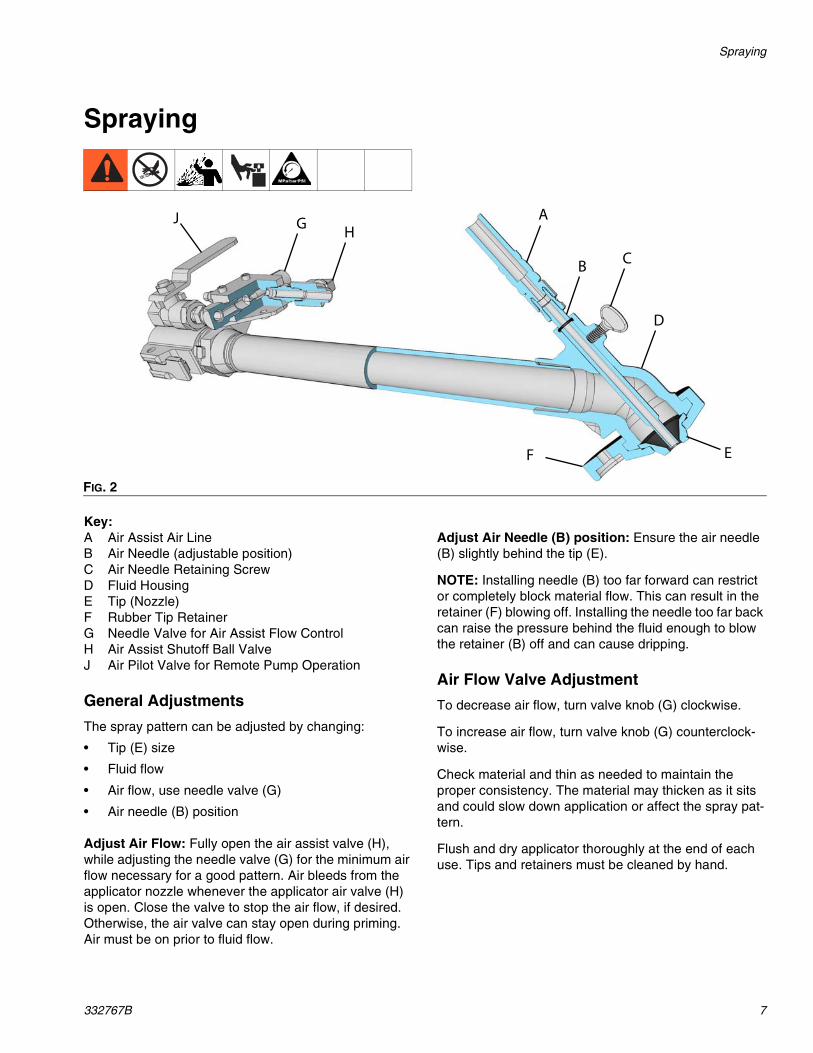
Spraying
Key:A Air Assist Air LineB Air Needle (adjustable position)C Air Needle Retaining ScrewD Fluid HousingE Tip (Nozzle)F Rubber Tip RetainerG Needle Valve for Air Assist Flow ControlH Air Assist Shutoff Ball ValveJ Air Pilot Valve for Remote Pump Operation
General Adjustments
The spray pattern can be adjusted by changing:
• Tip (E) size
• Fluid flow
• Air flow, use needle valve (G)
• Air needle (B) position
Adjust Air Flow: Fully open the air assist valve (H), while adjusting the needle valve (G) for the minimum air flow necessary for a good pattern. Air bleeds from the applicator nozzle whenever the applicator air valve (H) is open. Close the valve to stop the air flow, if desired. Otherwise, the air valve can stay open during priming. Air must be on prior to fluid flow.
Adjust Air Needle (B) position: Ensure the air needle (B) slightly behind the tip (E).
NOTE: Installing needle (B) too far forward can restrict or completely block material flow. This can result in the retainer (F) blowing off. Installing the needle too far back can raise the pressure behind the fluid enough to blow the retainer (B) off and can cause dripping.
Air Flow Valve Adjustment
To decrease air flow, turn valve knob (G) clockwise.
To increase air flow, turn valve knob (G) counterclock-wise.
Check material and thin as needed to maintain the proper consistency. The material may thicken as it sits and could slow down application or affect the spray pat-tern.
Flush and dry applicator thoroughly at the end of each use. Tips and retainers must be cleaned by hand.
FIG. 2
C
D
EF
B
AHGJ

Spraying
8 332767B
Material Flow Adjustments
For a lighter spray pattern, adjust the air needle (B) closer to the fluid nozzle and/or reduce the fluid flow.
For a heavier spray pattern, adjust the air needle (B) far-ther back from the fluid tip and/or increase the fluid flow.
NOTE: Withdrawing needle (B) too far can force air back into fluid hose, stopping material flow.
Spray Techniques
1. Test the spray pattern on cardboard. Hold the appli-cator 6-18 in. (150-450 mm) from the surface. Use this spraying distance for most applications.
2. Adjust fluid flow until material flow is adequate.
3. Adjust the applicator air assist needle valve to achieve a uniform round spray pattern.
4. Consider the size of aggregate in the material and the coarseness of the spray pattern. Larger nozzles allow heavier patterns.
5. Overlap each stroke 50%. A circular overlapping pattern may give the best results, and is obtained by grasping the flex-head and swinging the head around as the hose flexes.
When spraying small confined areas use the valve and knob to make fine adjustments without adjusting the pump.
Installing Nozzle Retaining Cap
1. Place nozzle retaining cap over top lip of applicator housing.
2. Insert screwdriver through hole in tab of nozzle retaining cap.
3. Push screwdriver head against notch on applicator tip and pry nozzle retaining cap over lip until it snaps into place.
Material Compatibility
The nylon hose in the Flex Applicator is compatible with solvents. The rubber gasket in the cam and groove inlet fitting and the rubber nozzle retainer should be hand cleaned and dried after each use.
ti14355a
NOTICE
To prevent the seals and rubber tip from swelling, do not leave solvent in the applicator when not in use.

Spraying
332767B 9

Parts
10 332767B
Parts
24T947 Flex Kit and 24T946 Pole Kit
† Parts included in spare spray head kit 24B956 (purchase sep-arately).
** Optional nozzle sizes available: 16A443: 3/16 in.16A444: 1/4 in.16A448: 1/2 in.16A449: 9/16 in.
◆ Parts included in needle valve kit 206264 (purchase sepa-rately). When received, unscrew assembly then install in man-ifold (114).
Orient as shown.
Apply pipe sealant to all non-swiveling pipe threads.
Apply lithium grease.
Turn needle fully counter-clockwise before screwing nut (119) into block (114).
Hand-tight.
Apply medium strength threadlocker to external threads.
Assemble items 120, 127, 135, and 119 before press fit of items 121 and 120.
Install bracket bolt (137) below handle (136).
1
2
3
4
6
7
8
9
122
113
118116
136
113
121119127, 135116
114
117
115
104
103102
101
137
112
111
124
110
105
109106
108
107
1
1
6
3
7 4
9
9
120
134
Ref Part Description Qty101 191633 TUBE, coupled, 30 in.
(model 24T946)1
24T322 TUBE, coupled, flexible, 1 in. ID, nylon core, 23 in. (model 24T947)
1
102 16V985 BRACKET, manifold, air 1103 113114 NUT, lock 1104 289874 KIT, repair, coupler 1104a 16W507 KIT, gasket, nitrile, 6-pack105† 16A247 HOUSING, head, applicator 1106a† 16A405 CAP, retaining, nozzle, medium hardness 1106b† 16A421 CAP, retaining, nozzle, hard 1107†** 16A445 NOZZLE, applicator, 5/16 in., stainless steel 1108† 16A446 NOZZLE, applicator, 3/8 in., stainless steel 1109† 16A447 NOZZLE, applicator, 7/16 in., stainless steel 1110† 100085 SCREW, thumb 1111† 190947 NEEDLE, air 1112† M70895 BUSHING, reducer 1113 113601 HOSE, air, coupled, 31.5 in. (model 24T946) 1
113377 HOSE, air, coupled, 21.0 in. (model 24T947) 1114 16V986 MANIFOLD, air 1115 100840 FITTING, elbow, street 1116 156971 FITTING, nipple, short 2117 113329 VALVE, ball, vented, 1/4 in. 1118 15B565 VALVE, ball 1119◆ --- NUT, packing 1120◆ --- NEEDLE, valve 1
121◆ --- KNOB, adjusting 1122 111235 SCREW, machine, panhead 3124† 121399 PACKING, o-ring, 012, FX-75 1127◆ 157628 PACKING, o-ring, Buna-N 1133 127311 FITTING, compress, 1/4 npt x 1/4 tube 1134 169970 FITTING, line air 1135◆ 166531 WASHER, non-metallic 1136 16W587 HANDLE, applicator
(included with model 24T946 only)1
137 16W588 CLAMP, handle(included with model 24T946 only)
1
Ref Part Description Qty

Technical Data
332767B 11
Technical Data
Texture ApplicatorsUS Metric
Maximum Fluid Working Pressure 1000 psi 7 MPa, 70 barMaximum Air Working Pressure 150 psi 1.0 MPa, 10 barMaximum Air Required(100 psi, needle valve fully open)
30 standard cubic feet per minute
0.85 cubic meters per minute
Fluid Inlet Size 1 in.(m) cam and groove (Graco HP)Air Inlet Size 1/4 quick disconnect pin fittingWetted Parts Aluminum, stainless steel, nitrile, nylon, plated carbon steel,
solvent resistant elastomerWeight
Model 24T946 9 lb 4.1 kgModel 24T947 7 lb 3.2 kg
Sound Data with Air (applicator only):Sound Pressure Level 118dB(A)*Sound Power Level 118dB(A)*
Notes* Spraying simulated acoustical texture under typical conditions as specified by the material manufacturer.

All written and visual data contained in this document reflects the latest product information available at the time of publication. Graco reserves the right to make changes at any time without notice.
For patent information, see www.graco.com/patents.
Original instructions. This manual contains English. MM 332767
Graco Headquarters: MinneapolisInternational Offices: Belgium, China, Japan, Korea
GRACO INC. AND SUBSIDIARIES • P.O. BOX 1441 • MINNEAPOLIS MN 55440-1441 • USA
Copyright 2013, Graco Inc. All Graco manufacturing locations are registered to ISO 9001.www.graco.com
Revision B, March 2014
Graco Standard WarrantyGraco warrants all equipment referenced in this document which is manufactured by Graco and bearing its name to be free from defects in material and workmanship on the date of sale to the original purchaser for use. With the exception of any special, extended, or limited warranty published by Graco, Graco will, for a period of twelve months from the date of sale, repair or replace any part of the equipment determined by Graco to be defective. This warranty applies only when the equipment is installed, operated and maintained in accordance with Graco’s written recommendations.
This warranty does not cover, and Graco shall not be liable for general wear and tear, or any malfunction, damage or wear caused by faulty installation, misapplication, abrasion, corrosion, inadequate or improper maintenance, negligence, accident, tampering, or substitution of non-Graco component parts. Nor shall Graco be liable for malfunction, damage or wear caused by the incompatibility of Graco equipment with structures, accessories, equipment or materials not supplied by Graco, or the improper design, manufacture, installation, operation or maintenance of structures, accessories, equipment or materials not supplied by Graco.
This warranty is conditioned upon the prepaid return of the equipment claimed to be defective to an authorized Graco distributor for verification of the claimed defect. If the claimed defect is verified, Graco will repair or replace free of charge any defective parts. The equipment will be returned to the original purchaser transportation prepaid. If inspection of the equipment does not disclose any defect in material or workmanship, repairs will be made at a reasonable charge, which charges may include the costs of parts, labor, and transportation.
THIS WARRANTY IS EXCLUSIVE, AND IS IN LIEU OF ANY OTHER WARRANTIES, EXPRESS OR IMPLIED, INCLUDING BUT NOT LIMITED TO WARRANTY OF MERCHANTABILITY OR WARRANTY OF FITNESS FOR A PARTICULAR PURPOSE.
Graco’s sole obligation and buyer’s sole remedy for any breach of warranty shall be as set forth above. The buyer agrees that no other remedy (including, but not limited to, incidental or consequential damages for lost profits, lost sales, injury to person or property, or any other incidental or consequential loss) shall be available. Any action for breach of warranty must be brought within two (2) years of the date of sale.
GRACO MAKES NO WARRANTY, AND DISCLAIMS ALL IMPLIED WARRANTIES OF MERCHANTABILITY AND FITNESS FOR A PARTICULAR PURPOSE, IN CONNECTION WITH ACCESSORIES, EQUIPMENT, MATERIALS OR COMPONENTS SOLD BUT NOT MANUFACTURED BY GRACO. These items sold, but not manufactured by Graco (such as electric motors, switches, hose, etc.), are subject to the warranty, if any, of their manufacturer. Graco will provide purchaser with reasonable assistance in making any claim for breach of these warranties.
In no event will Graco be liable for indirect, incidental, special or consequential damages resulting from Graco supplying equipment hereunder, or the furnishing, performance, or use of any products or other goods sold hereto, whether due to a breach of contract, breach of warranty, the negligence of Graco, or otherwise.
FOR GRACO CANADA CUSTOMERSThe Parties acknowledge that they have required that the present document, as well as all documents, notices and legal proceedings entered into, given or instituted pursuant hereto or relating directly or indirectly hereto, be drawn up in English. Les parties reconnaissent avoir convenu que la rédaction du présente document sera en Anglais, ainsi que tous documents, avis et procédures judiciaires exécutés, donnés ou intentés, à la suite de ou en rapport, directement ou indirectement, avec les procédures concernées.
Graco InformationFor the latest information about Graco products, visit www.graco.com.
TO PLACE AN ORDER, contact your Graco distributor or call to identify the nearest distributor.Phone: 612-623-6921 or Toll Free: 1-800-328-0211 Fax: 612-378-3505