monotig 160ip son - · pdf filearc rays can burn eyes and skin ... for example, a welder with...
TRANSCRIPT

MONOTIG 160İP
DC INVERTER TIG
WELDING MACHINE
2.3.1
2.3.2 Gas Connections
2.3.3 Torch Cooling System (Optional)
2.3.4 Preparing the Torch
2.3.5 Torch Connections
2.3.6
2.3.7 Changing the Tungsten Electrode
3. OPERATION
3.1 CONTROL PANEL
3.2 TIG CYCLE
3.3 MENU STRUCTURE
3.3.1 TIG Welding Process
3.3.2 Usage of the TIG Welding Modes
3.3.3 MMA Welding Process
3.3.4 Error Message
SAFETY RULES
1. TECHNICAL INFORMATION
1.1 GENERAL EXPLANATIONS
1.2 COMPONENTS OF MONOTIG 160iP
1.3 DATA PLATE
1.4 TECHNICAL SPECIFICATIONS
1.5 ACCESSORRIES
2. INSTALLATION
2.1 UPON RECEIPT AND CLAIMS
2.2 INSTALLATION AND WORKING RECOMMENDATIONS
2.3 CONNECTIONS FOR TIG WELDING
Mains Connection and Switching ON
Earth Clamp Connections
2.4 CONNECTIONS FOR MMA WELDING
4. MAINTENANCE AND TROUBLESHOOTING
4.1 PERIODIC MAINTENANCE
4.2 NONPERIODIC MAINTENANCE
4.3 TROUBLESHOOTING
APPENDIX 1: SPARE PARTS
APPENDIX 2: ELECTRICAL DIAGRAM
..............
.....................................................................................................................................8
...............................................................................................................................................9
................................................................................................................9
.......................................................................9
......................................................................................................9
..............................................................................................9
.............................................................................................................................9
...................................................................................................10
.......................................................................................................................10
.........................................................................................................................10
..............................................................................................................10
.................................................................................................................................................2
...........................................................................................................6
....................................................................................................................6
.......................................................................................................6
.............................................................................................................................................7
...............................................................................................................7
.................................................................................................10
..................................................................................................11
.................................................................................................................................................12
..................................................................................................................................12
.............................................................................................................................................13
..............................................................................................................................13
.....................................................................................................................14
.................................................................................................14
..................................................................................................................14
...............................................................................................................................14
..............................................................................................15
.............................................................................................................15
.....................................................................................................15
.....................................................................................................................15
..........................................................................................................................16
...........................................................................................................17
1MONOTIG 160ip
CONTENTS
2 MONOTIG 160ip
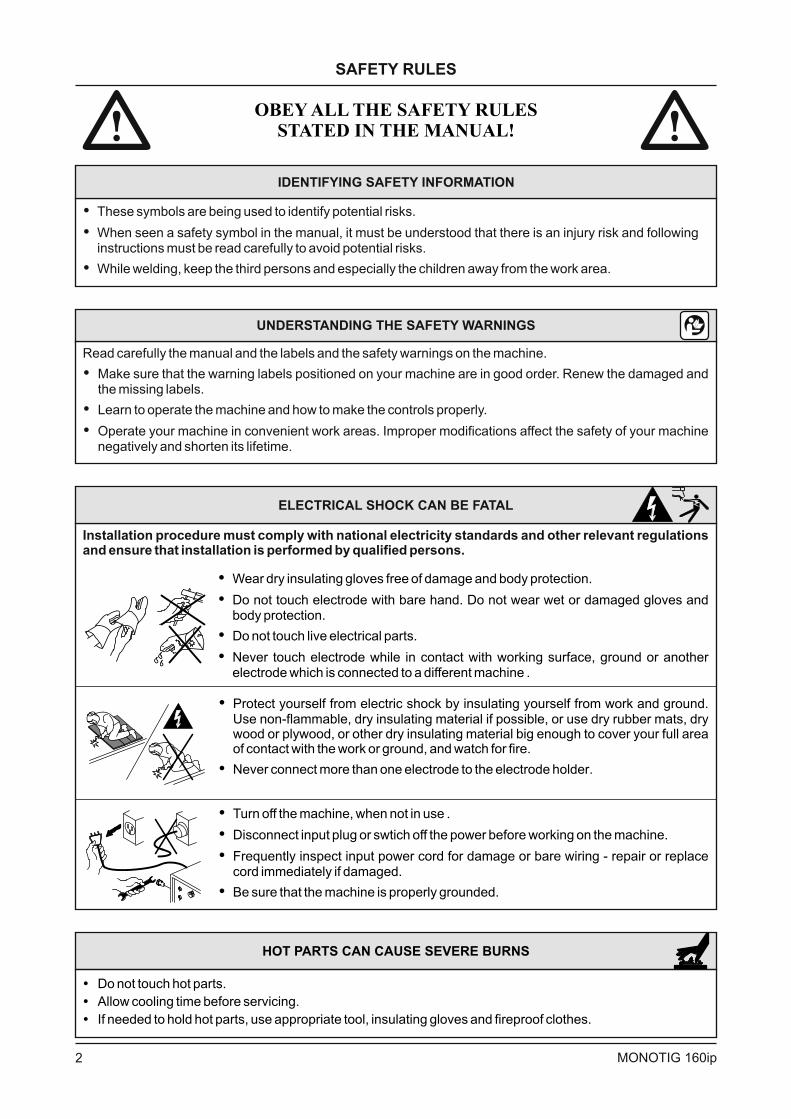
IDENTIFYING SAFETY INFORMATION
�
�
�
These symbols are being used to identify potential risks.
When seen a safety symbol in the manual, it must be understood that there is an injury risk and followinginstructions must be read carefully to avoid potential risks.
While welding, keep the third persons and especially the children away from the work area.
UNDERSTANDING THE SAFETY WARNINGS
Read carefully the manual and the labels and the safety warnings on the machine.
Make sure that the warning labels positioned on your machine are in good order. Renew the damaged andthe missing labels.
Learn to operate the machine and how to make the controls properly.
Operate your machine in convenient work areas. Improper modifications affect the safety of your machinenegatively and shorten its lifetime.
�
�
�
SAFETY RULES
ELECTRICAL SHOCK C FATALAN BE
Installation procedure must comply with national electricity standards and other relevant regulationsand ensure that installation is performed by qualified persons.
�
�
�
�
Wear dry insulating gloves and body protection.
Do not touch electrode with bare hand. Do not wear wet or damaged gloves andbody protection.
Do not touch live electrical parts
Never touch electrode while in contact with working surface, ground or anotherelectrode which is connected to a different machine
free of damage
.
.
�
�
Protect yourself from electric shock by insulating yourself from work and ground.Use non-flammable, dry insulating material if possible, or use dry rubber mats, drywood or plywood, or other dry insulating material big enough to cover your full areaof contact with the work or ground, and watch for fire.
Never connect more than electrode to the .one electrode holder
�
�
�
�
Turn off the machine, when not in use
Disconnect input plug or power before working on machine.
Frequently inspect input power cord for damage or bare wiring - repair or replacecord immediately if damaged.
Be sure ground
.
swtich off the the
that the machine is properly ed.
HOT PARTS CAN CAUSE SEVERE BURNS
�
�
�
Do not touch hot parts
Allow cooling time before servicing
hot parts, use appropriate tool, insulating gloves and fireproof clothes.
.
.
If needed to hold
OBEY ALL THE SAFETY RULES
STATED IN THE MANUAL!
3MONOTIG 160ip
SAFETY RULES
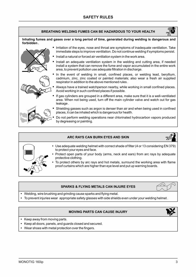
BREATHING WELDING FUMES CAN BE HAZARDOUS TO YOUR HEALTH
Inhaling fumes and gases over a long period of time, generated during welding is dangerous andforbidden .
�
�
�
�
�
�
�
�
Irritation of the eyes, nose and throat are symptoms of inadequate ventilation. Takeimmediate steps to improve ventilation. Do not continue welding if symptoms persist
Install a natural or forced air ventilation system in the work area
Install an adequate ventilation system in the welding and cutting area, if neededinstall a system that can remove the fume and vapor accumulated in the entire workarea, to prevent pollution use adequate filtration in discharge
In the event of welding in small, confined places, or welding lead, beryllium,cadmium, zinc, zinc coated or painted materials; also wear a fresh air suppliedrespirator in addition to the above mentioned rules
Always have a trained watchperson nearby, while working in small confined places.Avoid working in such confined places if possible
If gas cylinders are grouped in a different area, make sure that it is a well-ventilatedarea. When not being used, turn off the main cylinder valve and watch out for gasleakage
Shielding gasses such as argon is denser than air and when being used in confinedplaces, can be inhaled is dangerous for health
Do not perform welding operations near chlorinated hydrocarbon vapors producedby degreasing or painting
.
.
.
.
.
.
it which .
.
ARC RAYS CAN BURN EYES AND SKIN
�
�
�
Use adequate welding helmet with correct shade of filter (4 or 13 considering EN 379)to protect your eyes and face
Protect open parts of your body (arms, neck and ears) from arc rays by adequateprotective clothing
To protect others by arc rays and hot metals, surround the working area with flameproof curtains which are higher than eye level and put up warning boards.
.
.
SPARKS & FLYING METALS CAN INJURE EYES
�
�
Welding, wire brushing and grinding cause sparks and flying metal.
To prevent injuries wear appropriate safety glasses with side shields even under your welding helmet .
MOVING PARTS CAN CAUSE INJURY
�
�
�
Keep away from moving parts
Keep all doors, panels, and guards closed and secured
Wear shoes with metal protection over the fingers.
.
.
4 MONOTIG 160ip
SAFETY RULES
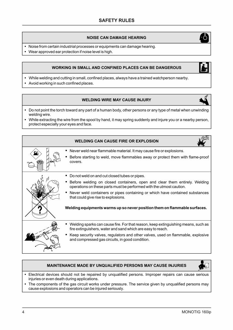
NOISE CAN DAMAGE HEARING
�
�
Noise from certain industrial processes or equipments can damage hearing.
Wear approved ear protection if noise level is high.
WORKING IN SMALL AND CONFINED PLACES CAN BE DANGEROUS
�
�
While welding and cutting in small, confined places, always have a trained watchperson nearby
Avoid working in such confined places
.
.
WELDING CAN CAUSE FIRE OR EXPLOSION
�
�
Never weld near flammable material. It may cause fire or explosions.
Before starting to weld, move flammables away or protect them with flame-proofcovers.
�
�
�
Do not weld on and cut closed tubes or pipes
Before welding on closed containers, open and clear them entirely. Weldingoperations on these parts must be performed with the utmost caution
Never weld containers or pipes containing or which have contained substancesthat could give rise to explosions
.
.
.
Welding equipments warms up so never position them on flammable surfaces.
�
�
Welding sparks can cause fire. For that reason, keep extinguishing means, such asfire extinguishers, water and sand easy reach
security valves, regulators and other valves on flammable, explosiveand compressed gas circuits in good condition
which are to .
Keep , used, .
WELDING WIRE MAY CAUSE INJURY
�
�
Do not point the torch toward any part of a human body, other persons or any type of metal when unwindingwelding wire
While extracting the wire from the spool by hand, it may spring suddenly and injure you or a nearby person,protect especially your eyes and face.
.
MAINTENANCE MADE BY UNQUALIFIED PERSONS MAY CAUSE INJURIES
�
�
Electrical devices should not be repaired by unqualified persons. Improper repairs can cause seriousinjuries or even death during applications
The components of the gas circuit works under pressure. The service given by unqualified persons maycause explosions and operators can be injured seriously
.
.
5MONOTIG 160ip
SAFETY RULES
FALLING UNIT CAN CAUSE INJURY
Wrong positioned power source or other equipment may cause serious injury to persons or damageto objects.
�
�
�
�
While repositioning the power source always carry by using the lifting eye. Never pull cable, hose or torch.Always carry the gas cylinders separately
Before carrying the welding and cutting equipment, disassemble all the connections between andseparately carry the small ones by handgrips and the big ones by lifting eyes or by using appropriatevehicles like forklifts
Install your machine on flat platforms having maximum 10 that it does not fall over. Install it on wellventilated, non-confined places away from the dust, also avoiding the risk of falling caused by cables andhoses. For gas cylinders not to fall over, attach it to the mobile machine or to the wall with a chain
Ensure that operators easily reach the controls and connections on the machine.
.
.
° slope
.
OVERUSE CAN CAUSE OVERHEATING
�
�
�
�
Allow cooling period; follow rated duty cycle
Reduce current or reduce duty cycle before starting to weld again
Do not block airflow t unit.
Do not filter airflow to unit without the approval of manufacturer
.
.
hrough the
.
ARC WELDING CAN CAUSE INTERFERENCE
�
�
�
�
�
�
Electromagnetic energy arising during welding and cutting operations can interfere with sensitive electronicequipment such as microprocessors, computers, and computer-driven equipment such as robots
Be sure all equipment in the welding area is electromagnetically compatible
To reduce possible interference, keep weld cables as short as possible, close together, and down low, suchas on the floor
To avoid possible EMC damages, locate welding operation as far as possible (100 meters) from anysensitive electronic equipment
Be sure this welding machine is installed and grounded according to this manual
If interference still occurs, the user must take extra measures such as moving the welding machine, usingshielded cables, using line filters, or shielding the work area
.
.
.
.
.
.
� Do not expose the welding machine to rain, protect from water drops and vapour.
PROTECTION
ENERGY EFFICIENCY
�
�
�
Choose appropriate welding method and welding machine for your work.
Choose appropriate welding current and welding voltage for the material and its thickness.
If you will have a long break after welding, turn off the machine after cooler fan cooled the machine.
2
3
4
5 6
7
8
1
9
10
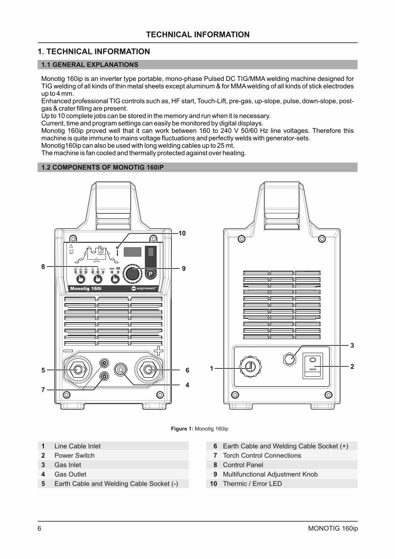
1.2 COMPONENTS OF MONOTIG 160iP
Figure 1: Monotig 160ip
Line Cable Inlet
Earth Cable and Welding Cable Socket (-)
Power Switch
Gas Inlet
Gas Outlet
Earth Cable and Welding Cable Socket (+)
Adjustment Knob
Thermic / Error LED
Torch Control Connections
Control Panel
Multifunctional
Monotig 160ip is an inverter type portable, mono-phase Pulsed DC TIG/MMA welding machine designed forTIG welding of all kinds of thin metal sheets except aluminum & for MMAwelding of all kinds of stick electrodesup to 4 mm.Enhanced professional TIG controls such as, HF start, Touch-Lift, pre-gas, up-slope, pulse, down-slope, post-gas & crater filling are present.Up to 10 complete jobs can be stored in the memory and run when it is necessary.Current, time and program settings can easily be monitored by digital displays.Monotig 160ip proved well that it can work between 160 to 240 V 50/60 Hz line voltages. Therefore thismachine is quite immune to mains voltage fluctuations and perfectly welds with generator-sets.Monotig160ip can also be used with long welding cables up to 25 mt.The machine is fan cooled and thermally protected against over heating.
1
2
3
4
5
6
7
8
9
10
6 MONOTIG 160ip
TECHNICAL INFORMATION
1. TECHNICAL INFORMATION
1.1 GENERAL EXPLANATIONS
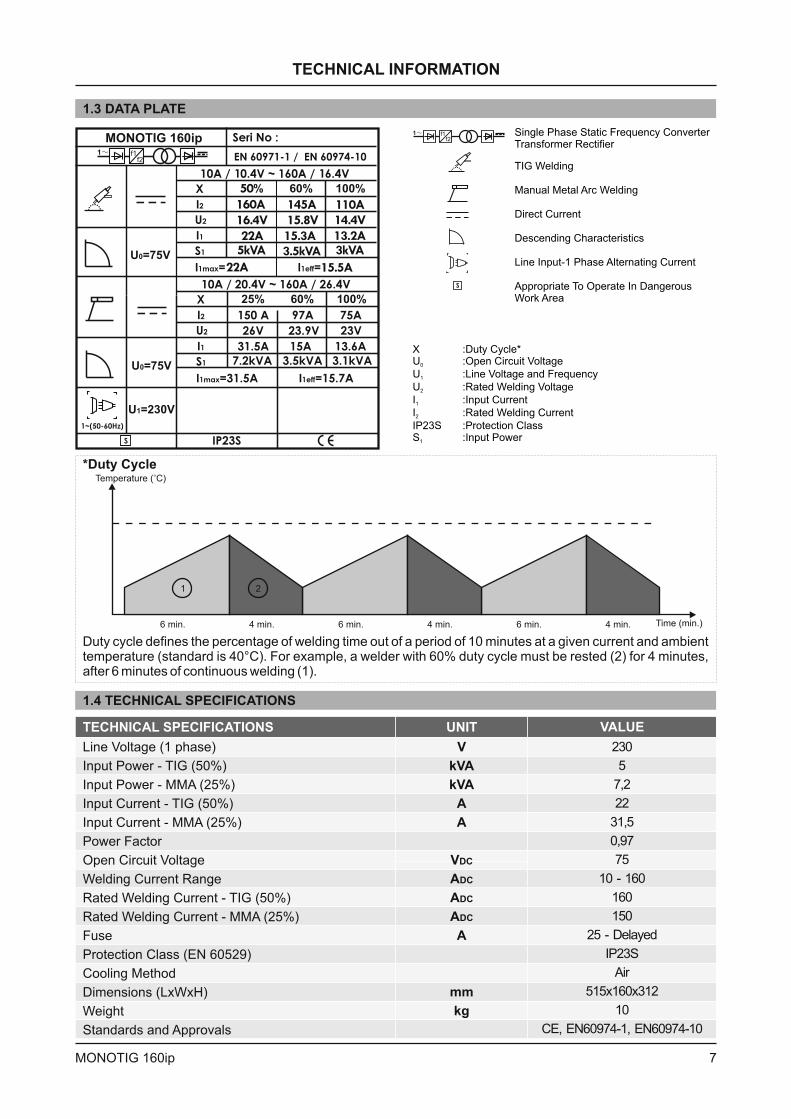
TIG Welding
Manual Metal Arc Welding
Direct Current
Descending Characteristics
Line Input-1 Phase Alternating Current
X :Duty Cycle*U :Open Circuit Voltage
U :Line Voltage and Frequency
U :Rated Welding Voltage
I :Input Current
I :Rated Welding Current
IP23S :Protection ClassS :Input Power
0
1
2
1
2
1
Single Phase Static Frequency ConverterTransformer Rectifier
*Duty Cycle
1 2
Temperature ( C)°
Time (min.)6 min. 6 min. 6 min.4 min. 4 min. 4 min.
Duty cycle defines the percentage of welding time out of a period of 10 minutes at a given current and ambienttemperature (standard is 40°C). For example, a welder with 60% duty cycle must be rested (2) for 4 minutes,after 6 minutes of continuous welding (1).
1.4 TECHNICAL SPECIFICATIONS
VALUEUNITTECHNICAL SPECIFICATIONS
Line Voltage phase
50%
25%
50%
25%
Power Factor
Open Circuit Voltage
Welding Current Range
(50%
- MMA 25%
Fuse
Protection Class (EN 60529)
Cooling Method
Dimensions (LxWxH)
Weight
Standards and Approvals
(1 )
( )
( )
( )
( )
)
( )
Input Power - TIG
Input Power - MMA
Input Current - TIG
Input Current - MMA
Rated Welding Current - TIG
Rated Welding Current
V
kVA
kVA
A
A
V
A
A
A
mm
kg
DC
DC
DC
ADC
2 03
5
7,2
22
31,5
0,97
75
10 - 160
160
150
25 - Delayed
IP23S
Air
515x160x312
10
CE, EN60974-1, EN60974-10
7MONOTIG 160ip
Appropriate To Operate In DangerousWork Area
1.3 DATA PLATE
TECHNICAL INFORMATION
MONOTIG 160ip
22A 15.5A
160A
16.4V
22A
5kVA 3.5kVA 3kVA
145A
15.8V
15.3A
110A
14.4V
13.2A
50
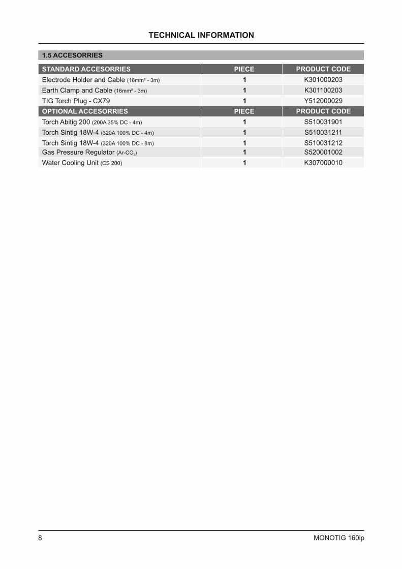
1.5 ACCESORRIES
STANDARD ACCESORRIES PIECE PRODUCT CODE
K301000203
Y512000029
K301100203
1
1
1
Electrode Holder and Cable (16mm² - 3m)
TIG Torch Plug - CX79
Earth Clamp and Cable (16mm² - 3m)
OPTIONAL ACCESORRIES PIECE PRODUCT CODE
S510031901
S510031212
K307000010
S510031211
S520001002
1
1
1
1
1
Torch Abitig 200 (200A 35% DC - 4m)
Torch Sintig 18W-4 (320A 100% DC - 8m)
Water Cooling Unit (CS 200)
Torch Sintig 18W-4 (320A 100% DC - 4m)
Gas Pressure Regulator (Ar-CO )2
TECHNICAL INFORMATION
8 MONOTIG 160ip
INSTALLATION
2.1 UPON RECEIPT AND CLAIMS
�
�
Be sure that you have received all the items thatyou have ordered. In case of any item is missing ordamaged, contact your supplier immediately.
In the event of damaged or missing delivery,
it to the shipping agency and MAGMAMEKATRONIK with the photocopy of shipping bill.
E-mail: [email protected]
Fax: +90 236 226 27 28
drawup a record, take a photo of the damage andreport
�
ú
ú
ú
ú
ú
ú
Standard box contains:
Power Source
H Cable
Earth Clamp Cable
TIG Torch Plug
Transportation Belt
User Manual
Electrode older
2. INSTALLATION
2.2 INSTALLATION AND WORKING RECOMMENDATIONS
9MONOTIG 160ip
�
�
DO NOT USE THE MACHINE WITH LONGCABLES AT CONSTRUCTION SITES!
cable 220V/50 Hz and thesecables are not suitable to in harshenvironments, they can easily wear and tear whichmay lead to electric leakage to the metals wherewelders may be working on. ELECTRIK SHOCKCAN KILL or cause people to FALL DOWN from
. I ALWAYSuse long WELDING CABLES
for safety reasons
For a better performance, keep the machine atleast 20 cm away from the surrounding objects.Beware of excessive heat, dust and humidityaround the machine. Try not to operate themachine under direct sunlight. Machines shouldbe operated on when ambientair temperature exceeds .
MAINSMains s are under
be used
elevated working areas t isrecommended to erinstead of MAINS CABLES .
lower capacities40ºC
�
�
�
�
�
�
Avoid welding at outdoors where it is windy andrainy, if this is a must, protect the welding area withcurtains, mobile screens or tents.
se suitable welding fume extraction systems.Use breathing apparatus if there is a risk ofinhaling in confined places.Respect the duty cycles given at the data plate.Exceeding the duty cycles frequently can damagethe machine and this would void the warranty.
Do not use stronger fuses than those stated on thedata plate
Ensure that the earth clamp is tightly connected asclose as possible to the welding location. Do not letwelding current flow through any media other thanwelding cables; e.g. over the machine itself, gastubes, chains, ball bearings, etc
U
.
.
Secure the gas cylinder to a wall by a chain.
2.3 CONNECTIONS FOR TIG WELDING
2.3.2 Gas Connections
�
�
Switch the machine t the position ando “OFF” “0”
insert the plug into the socket.
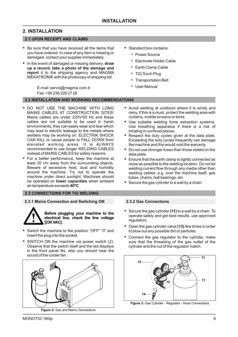
SWITCH ON the machine via power switch (2).Observe that the switch itself and the led displaysin the front panel li s, also you should hear thesound of the cooler fan.
t
Before plugging your machine to theelectrical line, check the line voltage[230 VAC].
2.3.1 Mains Connection and Switching ON
Figure 2: Gas and Mains Connections
Figure 3: Gas Cylinder - Regulator - Hose Connections
12
15
13
11
14
� Secure the gas cylinder to a wall by a chain. Tooperate safely and get best results, use approvedregulators.
(11)
�
�
Open the gas cylinder valve few times in orderto blow out any possible dirt or particles.
Connect the gas regulator to the cylinder, makesure that the threading of the gas outlet of thecylinder and the nut of the regulator match.
(13)
INSTALLATION
10 MONOTIG 160ip
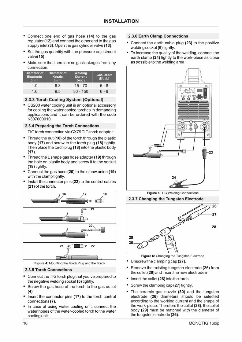
2.3.4 Preparing the Torch Connections
TIG torch connection via CX79 TIG torch adaptor :
Thread the nut of the torch through the plasticbody and screw to the torch plug tightly.Then place the torch plug into the plastic body
.
Thread the L shape gas hose adapter throughthe hole on plastic body and screw it to the socket
tightly.
Connect the gas hose to the elbow unionwith the clamp tightly.
Install the connector pins to the control cablesof the torch.
�
�
�
�
(16)(17) (18)
(18)(17)
(19)
(18)
(20) (19)
(22)(21)
2.3.3 Torch Cooling System (Optional)
� CS200 water cooling unit is an optional accessoryfor cooling the water cooled torches in demandingapplications and it can be ordered with the codeK307000010.
2.3.7 Changing the Tungsten Electrode
28
27
26
30
29
Figure 6: Changing the Tungsten Electrode
�
�
�
�
�
Unscrew the clamping cap .
Remove the existing tungsten electrode fromthe collet and insert the new electrode in.
Insert the collet into the torch.
Screw the clamping cap tightly.
(27)
(26)(28)
(28)
(27)
(30)(26)
(28)(29)
(26)
The ceramic gas nozzle and the tungstenelectrode diameters should be selectedaccording to the working current and the shape ofthe work-piece. Therefore the collet , the colletbody must be matched with the diameter ofthe tungsten electrode .
2.3.5 Torch Connections
�
�
�
�
Connect the TIG torch plug that you ve prepared to
the negative welding socket tightly.
Screw the gas hose of the torch to the gas outlet.
Insert the connector pins to the torch controlconnections .
In case of using water cooling unit, connect thewater hoses of the water-cooled torch to the watercooling unit.
'
(5)
(4)
(17)(7)
1716 18
19
20
2221
Figure 4: Mounting the Torch Plug and the Torch
5 74
6
24
23
Figure 5: TIG Welding Connections
Gas Debit(lt/dak)
6 - 8
6 - 8
Diameter ofElectrode
(mm)
Diameter ofNozzle(mm)
WeldingCurrent
(A )DC
1.0
1.6
6.3
9.5
15 - 70
30 - 150
�
�
�
Connect one end of gas hose to the gasregulator and connect the other end to the gassupply inlet . Open the gas cylinder valve .
Set the gas quantity with the pressure adjustmentvalve .
Make sure that there are no gas leakages from anyconnection.
(14)(12)
(3) (13)
(15)
�
�
Connect.
the earth cable plug to the positivewelding socket tightly
(23)6( )
To increase the quality of the welding, connect theearth clamp tightly to the work-piece as closeas possible to the welding area.
(24)
2.3.6 Earth Clamp Connections
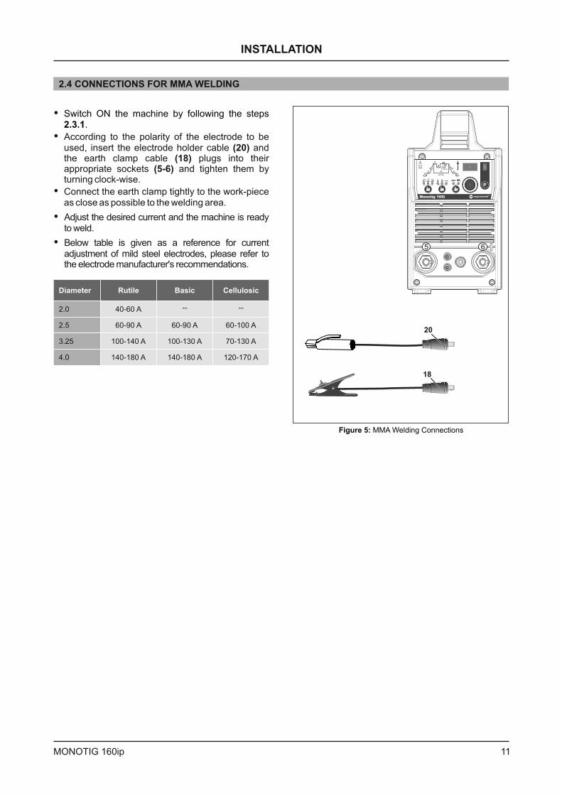
2.4 CONNECTIONS FOR MMA WELDING
�
�
�
�
�
According to the polarity of the electrode to beused, i the electrode holder cable andthe earth clamp cable plugs into theirappropriate sockets them
clock-wise
Below table is given as a reference for currentadjustment of mild steel electrodes, please refer tothe electrode manufacturer's recommendations.
nsert
and tighten byturning .
(20)(18)
5-6( )
Connect the earth clamp tightly to the work-pieceas close as possible to the welding area.
Adjust the desired current and the machine is readyto weld.
Switch ON the machine by following the steps.2.3.1
5 6
Figure 5: MMA Welding Connections
18
20
INSTALLATION
11MONOTIG 160ip
Diameter Rutile Basic Cellulosic
2.0
2.5
3.25
4.0
40-60 A
60-90 A 60-90 A 60-100 A
100-140 A 100-130 A 70-130 A
140-180 A 140-180 A 120-170 A
-- --
OPERATION
3. OPERATION
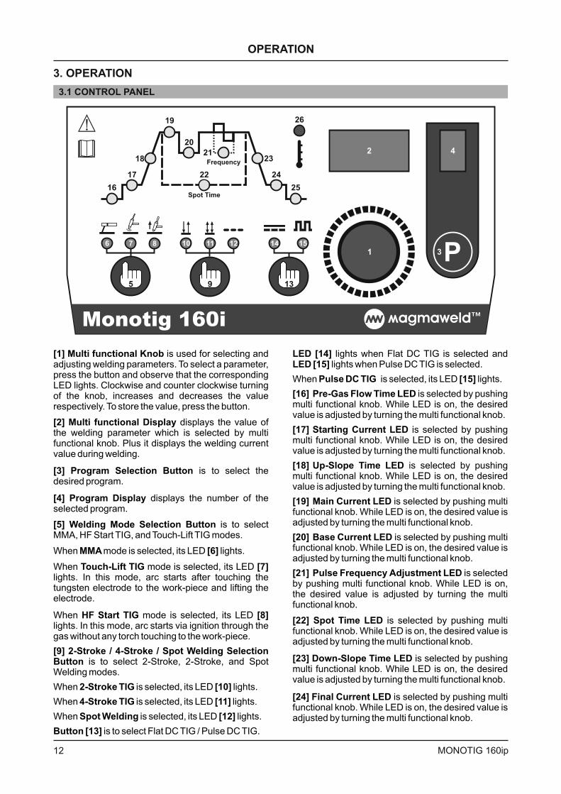
3.1 CONTROL PANEL
[1] Multi functional Knob
[2] Multi functional Display
[3] Program Selection Button
[4] Program Display
[5] Welding Mode Selection Button
MMA [6]
Touch-Lift TIG [7]
HF Start TIG [8]
[9] Stroke Stroke Spot Welding SelectionButton
2-Stroke TIG [10]
4-Stroke TIG [11]
Spot Welding [12]
Button [13]
is used for selecting andadjusting welding parameters. To select a parameter,press the button and observe that the correspondingLED lights. Clockwise and counter clockwise turningof the knob, increases and decreases the valuerespectively. To store the value, press the button.
displays the value ofthe welding parameter which is selected by multifunctional knob. Plus it displays the welding currentvalue during welding.
is to select thedesired program.
displays the number of theselected program.
is to selectMMA, HF Start TIG, and Touch-Lift TIG modes.
When mode is selected, its LED lights.
When mode is selected, its LEDlights. In this mode, arc starts after touching thetungsten electrode to the work-piece and lifting theelectrode.
When mode is selected, its LEDlights. In this mode, arc starts via ignition through thegas without any torch touching to the work-piece.
is to select 2-Stroke, 2-Stroke, and SpotWelding modes.
When is selected, its LED lights.
When is selected, its LED lights.
When is selected, its LED lights.
is to select Flat DC TIG / Pulse DC TIG.
2- / 4- /
Frequency
Spot Time
Monotig 160i
1
2
3
4
5
6 7 8
13
14 15
9
10 11 12
16
17
18
19
20
22
2123
24
25
26
LED [14]LED [15]
Pulse DC TIG [15]
[16] Pre-Gas Flow Time LED
[17] Starting Current LED
[18] Up-Slope Time LED
[19] Main Current LED
[20] Base Current LED
[21] Pulse Frequency Adjustment LED
[22] Spot Time LED
[23] Down-Slope Time LED
[24] Final Current LED
lights when Flat DC TIG is selected andlights when Pulse DC TIG is selected.
When is selected, its LED lights.
is selected by pushingmulti functional knob. While LED is on, the desiredvalue is adjusted by turning the multi functional knob.
is selected by pushingmulti functional knob. While LED is on, the desiredvalue is adjusted by turning the multi functional knob.
is selected by pushingmulti functional knob. While LED is on, the desiredvalue is adjusted by turning the multi functional knob.
is selected by pushing multifunctional knob. While LED is on, the desired value isadjusted by turning the multi functional knob.
is selected by pushing multifunctional knob. While LED is on, the desired value isadjusted by turning the multi functional knob.
is selectedby pushing multi functional knob. While LED is on,the desired value is adjusted by turning the multifunctional knob.
is selected by pushing multifunctional knob. While LED is on, the desired value isadjusted by turning the multi functional knob.
is selected by pushingmulti functional knob. While LED is on, the desiredvalue is adjusted by turning the multi functional knob.
is selected by pushing multifunctional knob. While LED is on, the desired value isadjusted by turning the multi functional knob.
12 MONOTIG 160ip
[25] Post Gas-Flow Time LED
[26] Thermal Error LED
is selected bypushing multi functional knob. While LED is on, thedesired value is adjusted by turning the multifunctional knob.
lights when machine isoverheated.
According to the modes, active and inactivefunctions are shown in the table below.
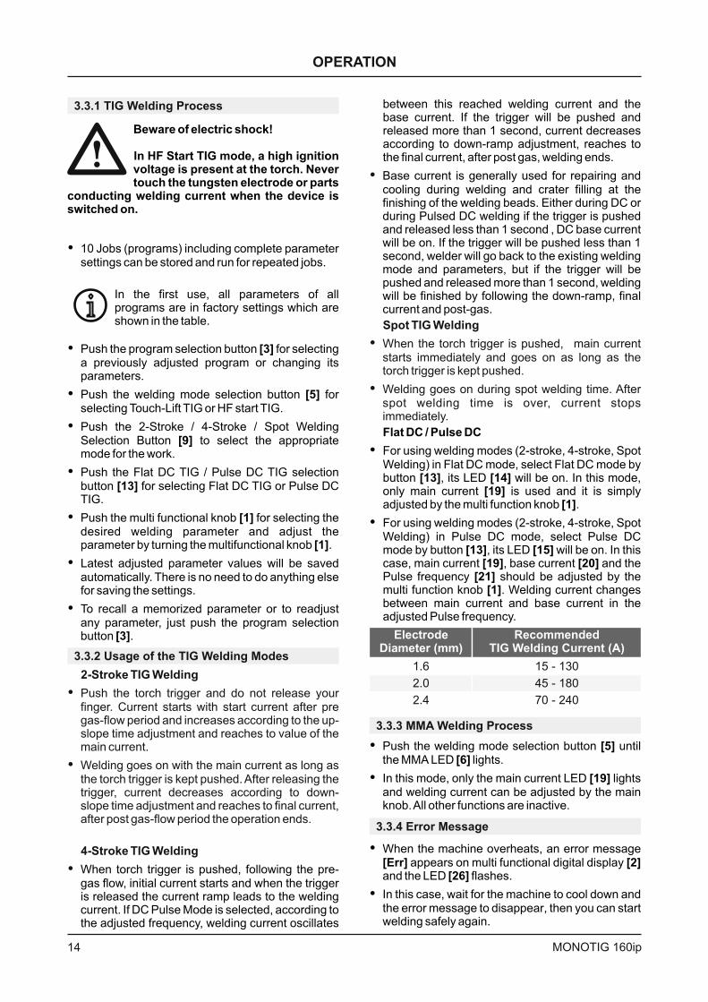
PARAMETERRANGE FACTORY
SETTINGLED
2-StrokeTIG
MMAWelding
4-StrokeTIG
SpotTIG
1 sec
20 A
1 sec
130 A
80 A
15 Hz
5 sec
1 sec
40 A
2 sec
16
17
18
19
20
21
22
23
24
25
0.1 - 10 sec
10 - 160 A
0.1 - 10 sec
10 - 160 A
10 - 160 A
0.1 - 2000 Hz
0.1 - 10 sec
0.1 - 10 sec
10 - 160 A
1 - 23 sec
Pre-Gas Flow Time
Start Current
Up-slope Time
Main Current
Base Current
Frequency
Spot Time
Down-slope Time
Final Current
Post-Gas Flow Time
DC DC DCPulse Pulse Pulse
P P P P P P P
P P P P P P
P P P P P P
P P P P P P
P P P P P P
P P P P P P
P P P P P P
PP
P P
P
P P
P
P
P
3.3 MENU STRUCTURE
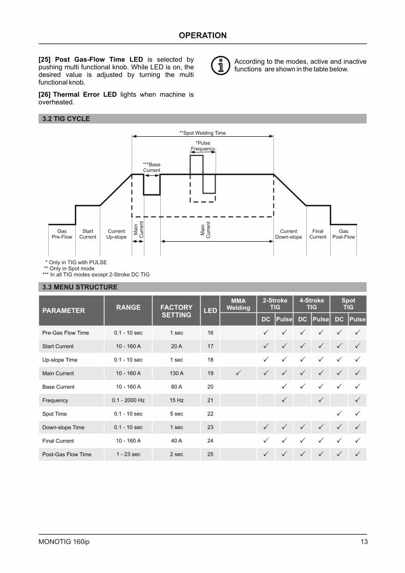
3.2 TIG CYCLE
* Only in TIG with PULSE** Only in Spot mode*** In all TIG modes except 2-Stroke DC TIG
i
OPERATION
GasPre-Flow
StartCurrent
CurrentUp-slope
CurrentDown-slope
FinalCurrent
GasPost-Flow
*PulseFrequency
***BaseCurrent
Ma
inC
urr
en
t
Ma
inC
urr
en
t
**Spot Welding Time
13MONOTIG 160ip
3.3.3 MMA Welding Process
�
�
Push the welding mode selection button untilthe MMA LED lights.
In this mode, only the main current LED lightsand welding current can be adjusted by the mainknob.All other functions are inactive.
[5][6]
[19]
3.3.1 TIG Welding Process
�
�
�
�
�
�
�
Push the program selection button for selectinga previously adjusted program or changing itsparameters.
Push the welding mode selection button forselecting Touch-Lift TIG or HF start TIG.
Push the Stroke Stroke Spot WeldingSelection Button to select the appropriatemode for the work.
Push the Flat DC TIG / Pulse DC TIG selectionbutton for selecting Flat DC TIG or Pulse DCTIG.
Push the multi functional knob for selecting thedesired welding parameter and adjust theparameter by turning the multifunctional knob .
Latest adjusted parameter values will be savedautomatically. There is no need to do anything elsefor saving the settings.
To recall a memorized parameter or to readjustany parameter, just push the program selectionbutton .
[3]
[5]
[9]
[13]
[1]
[1]
[3]
2- / 4- /
Beware of electric shock!
In HF Start TIG mode, a high ignitionvoltage is present at the torch. Nevertouch the tungsten electrode or parts
conducting welding current when the device isswitched on.
� 10 Jobs (programs) including complete parametersettings can be stored and run for repeated jobs.
In the first use, all parameters of allprograms are in factory settings which areshown in the table.
between this reached welding current and thebase current. If the trigger will be pushed andreleased more than 1 second, current decreasesaccording to down-ramp adjustment, reaches tothe final current, after post gas, welding ends.
Base current is generally used for repairing andcooling during welding and crater filling at thefinishing of the welding beads. Either during DC orduring Pulsed DC welding if the trigger is pushedand released less than 1 second , DC base currentwill be on. If the trigger will be pushed less than 1second, welder will go back to the existing weldingmode and parameters, but if the trigger will bepushed and released more than 1 second, weldingwill be finished by following the down-ramp, finalcurrent and post-gas.
�
�
�
Spot TIG Welding
When the torch trigger is pushed, main currentstarts immediately and goes on as long as thetorch trigger is kept pushed.
Welding goes on during spot welding time. Afterspot welding time is over, current stopsimmediately.
Flat DC Pulse DC
[13] [14][19]
[1]
[13] [15][19] [20]
[21][1]
/
�
�
For using welding modes (2-stroke, 4-stroke, SpotWelding) in Flat DC mode, select Flat DC mode bybutton , its LED will be on. In this mode,only main current is used and it is simplyadjusted by the multi function knob .
For using welding modes (2-stroke, 4-stroke, SpotWelding) in Pulse DC mode, select Pulse DCmode by button , its LED will be on. In thiscase, main current , base current and thePulse frequency should be adjusted by themulti function knob . Welding current changesbetween main current and base current in theadjusted Pulse frequency.
3.3.2 Usage of the TIG Welding Modes
3.3.4 Error Message
�
�
When the machine overheats, an error messageappears on multi functional digital display
and the LED flashes.
In this case, wait for the machine to cool down andthe error message to disappear, then you can startwelding safely again.
[Err] [2][26]
2-Stroke TIG Welding
4-Stroke TIG Welding
�
�
�
Push the torch trigger and do not release yourfinger. Current starts with start current after pregas-flow period and increases according to the up-slope time adjustment and reaches to value of themain current.
Welding goes on with the main current as long asthe torch trigger is kept pushed. After releasing thetrigger, current decreases according to down-slope time adjustment and reaches to final current,after post gas-flow period the operation ends.
When torch trigger is pushed, following the pre-gas flow, initial current starts and when the triggeris released the current ramp leads to the weldingcurrent. If DC Pulse Mode is selected, according tothe adjusted frequency, welding current oscillates
i
OPERATION
14 MONOTIG 160ip
ElectrodeDiameter (mm)
RecommendedTIG Welding Current (A)
1.6
2.0
2.4
15 - 130
45 - 180
70 - 240
4.2 NONPERIODIC MAINTENANCE
Contact tip and nozzle on the torch have to be cleaned regularly andchanged if required. Contact tips must be in good condition, longer tipsgenerally give better results.
NOTE: The above recommended maintenence periods are indicative, these may vary according to thework shop conditions.
4.3 TROUBLESHOOTING
�
�
If the Thermal Protection LED lights up while cooling fan is working and the machine doesn't weld;machine maybe overheated and stopped for auto protection due to overheat. Hot weather or working inhigh current values for long time may cause this. Let the machine on for a while in order to cool down itselfwith the cooling fan. After it cools enough, Thermal Protection LED fades away and the machine canweld.
When the lamp of power switch is lighting, cooling fan is working but the machine does not weld; turn offthe machine for 1 minute then turn it on again and try to weld. If it still doesn't weld,
(10)
(10)
(2)contact to your
authorized technical service.
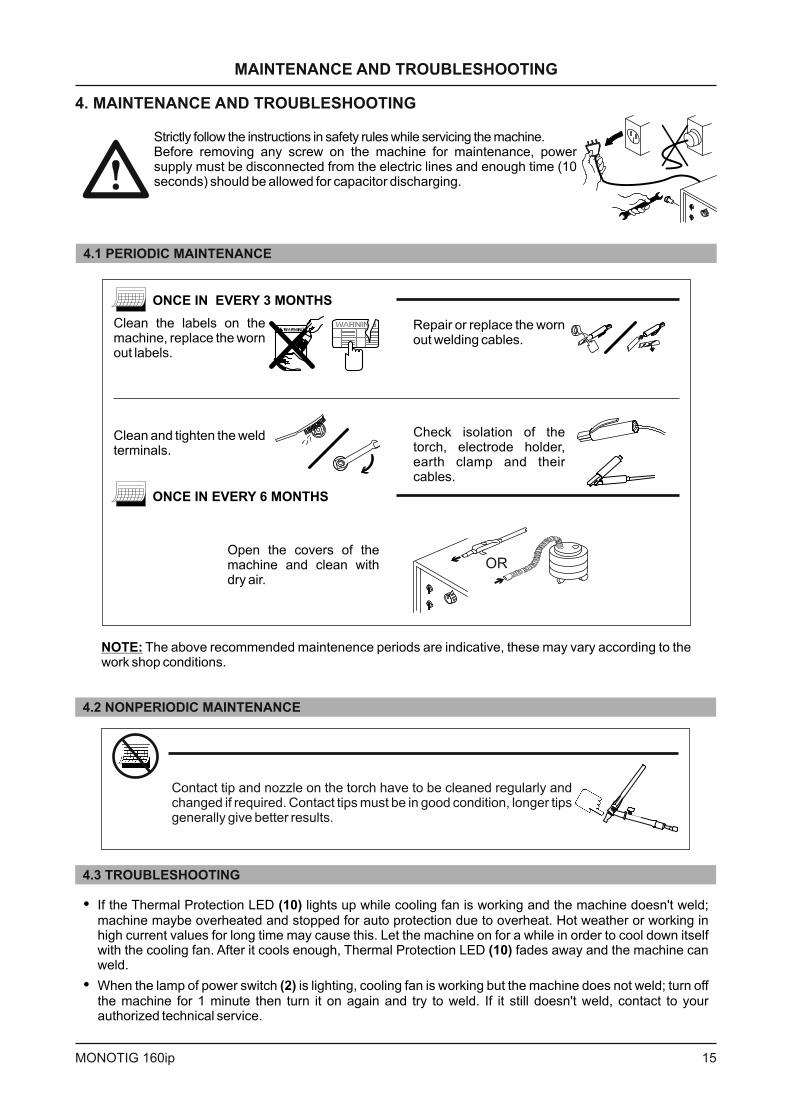
4.1 PERIODIC MAINTENANCE
Clean the labels on themachine, replace the wornout labels.
Repair or replace the wornout welding cables.
Clean and tighten the weldterminals.
Check isolation of thetorch, electrode holder,
and theircables.earth clamp
ONCE IN EVERY 3 MONTHS
ONCE IN EVERY 6 MONTHS
Open the covers of themachine and clean withdry air.
OR
Strictly follow the instructions in safety rules while servicing the machine.Before removing any screw on the machine for maintenance, powersupply must be disconnected from the electric lines and enough time (10seconds) should be allowed for capacitor discharging.
15MONOTIG 160ip
MAINTENANCE AND TROUBLESHOOTING
4. MAINTENANCE AND TROUBLESHOOTING
16 MONOTIG 160ip
1
2
3
4
5
6
7
8
9
10
11
12
13
14
15
16
17
18
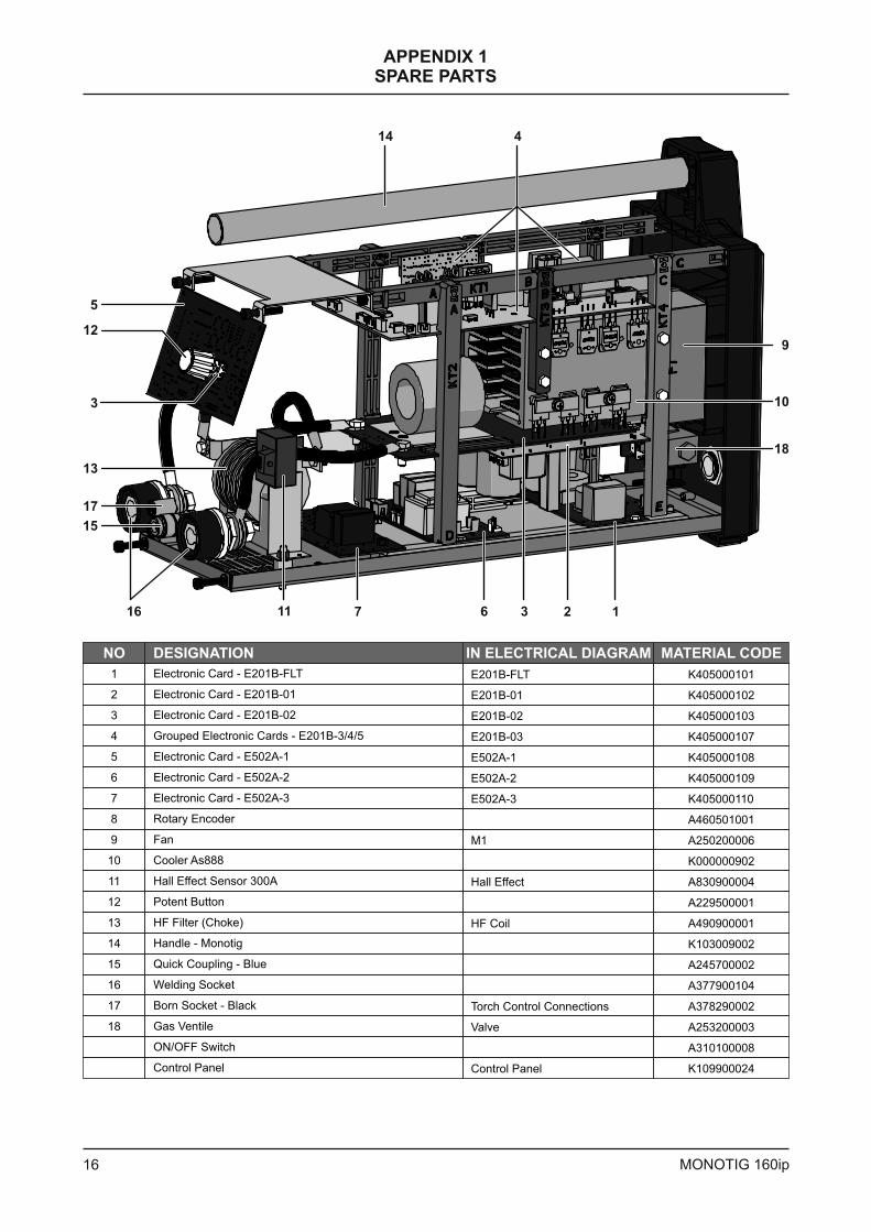
Electronic Card - E201B-FLT
Electronic Card - E201B-01
Electronic Card - E201B-02
Grouped Electronic Cards - E201B-3/4/5
Electronic Card - E502A-1
Electronic Card - E502A-2
Electronic Card - E502A-3
Rotary Encoder
Fan
Cooler As888
Hall Effect Sensor 300A
Potent Button
HF Filter (Choke)
Handle - Monotig
Quick Coupling - Blue
Welding Socket
Born Socket - Black
Gas Ventile
ON/OFF Switch
Control Panel
NO
E201B-FLT
E201B-01
E201B-02
E201B-03
E502A-1
E502A-2
E502A-3
M1
Hall Effect
HF Coil
Torch Control Connections
Valve
Control Panel
K405000101
K405000102
K405000107
A250200006
A310100008
K109900024
K405000103
K405000108
K405000109
K405000110
K000000902
A830900004
A229500001
A490900001
K103009002
A460501001
A245700002
A377900104
A378290002
A253200003
18
129
5
3
16 11 7
10
6
14
1
13
23
4
15
17
DESIGNATION IN ELECTRICAL DIAGRAM MATERIAL CODE
APPENDIX 1SPARE PARTS
17MONOTIG 160ip
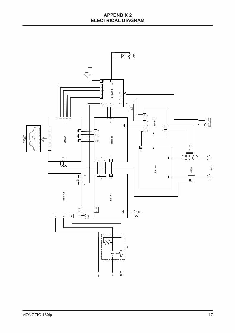
APPENDIX 2ELECTRICAL DIAGRAM
CO
NT
RO
LP
AN
EL
Torc
h C
ontr
ol
Connectiom
s
Valv
e

+90 236 226 27 00
+90 236 226 27 28
Made in Turkey
FACTORY
Organize Sanayi Bölgesi 5.Kısım 5503. Sokak No:1 MANİSA
www.magmaweld.com
OWM 05.04.2011