module 7 – power systems : tethers what is a tether? it is the lifeline for your rov the tether...
TRANSCRIPT
Module 7 – Power Systems: Tethers
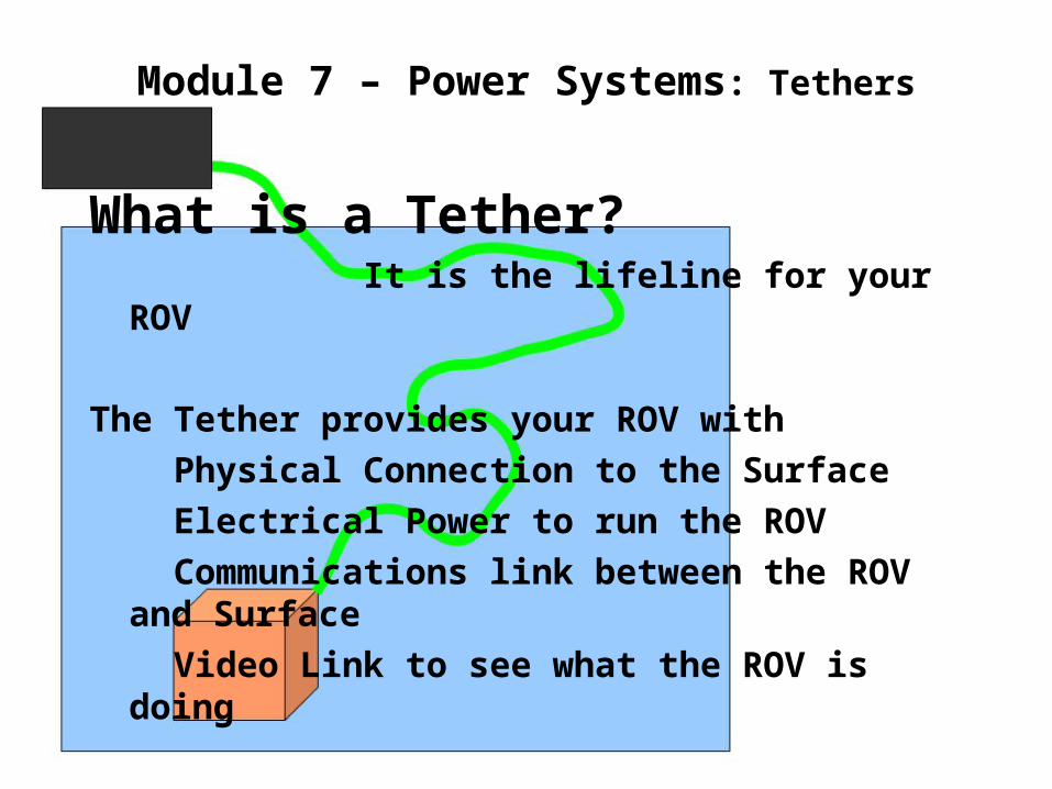
What is a Tether? It is the lifeline for your ROV
The Tether provides your ROV with Physical Connection to the Surface Electrical Power to run the ROV Communications link between the ROV
and Surface Video Link to see what the ROV is doing
Module 7 – Power Systems: Tethers
What is one of the biggest problems with tethers in small ROVs?
Length? Weight in Water? Flexibility? Drag? Voltage Drop? Strength?
ALLOFTHESE!!!
Module 7 – Power Systems: Tethers
Good Tether design takes all these factors into consideration
Length – Just as long as needed Weight in Water – Neutral if possible Flexibility – nice and flexible Drag – as small diameter possible Voltage Drop – the least possible Strength – nice and strong to pull the
ROV out if it dies.THERE IS A BIG PROBLEM HERE!!!EACH OF THESE CAUSE PROBLEMS FOR THE OTHERS!
Module 7 – Power Systems: Tethers
WHAT Do you mean?Too much length causes more voltage
dropIf you fix that by making it bigger the
tether is less flexible. It also becomes heavier and now is a big drag on the ROV.
If you try and make it really small and
just the right length, you may also have too much voltage drop.OK, what are we supposed to do?
Design a tether with all these items in mind!!!
Module 7 – Power Systems: Tethers
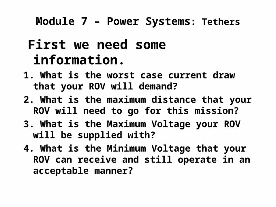
First we need some information.
1. What is the worst case current draw that your ROV will demand?
2. What is the maximum distance that your ROV will need to go for this mission?
3. What is the Maximum Voltage your ROV will be supplied with?
4. What is the Minimum Voltage that your ROV can receive and still operate in an acceptable manner?
Module 7 – Power Systems: Tethers
First we need some information.
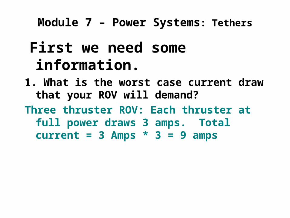
1. What is the worst case current draw that your ROV will demand?
Three thruster ROV: Each thruster at full power draws 3 amps. Total current = 3 Amps * 3 = 9 amps
Module 7 – Power Systems: Tethers
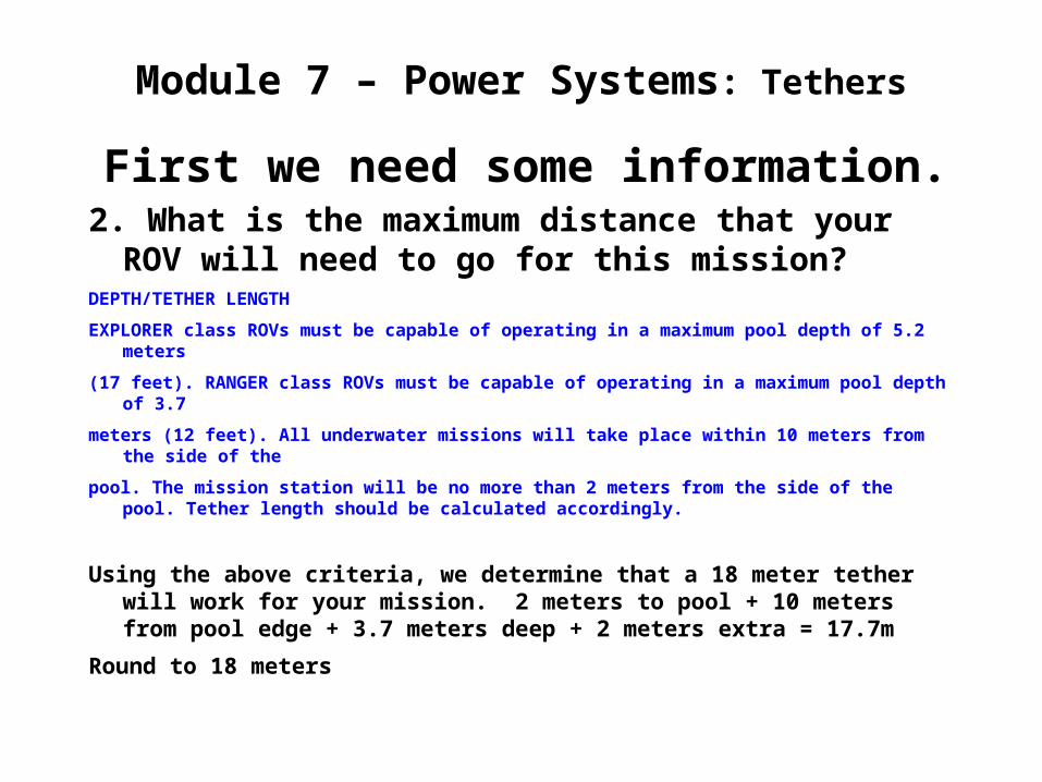
First we need some information.2. What is the maximum distance that your
ROV will need to go for this mission?DEPTH/TETHER LENGTH
EXPLORER class ROVs must be capable of operating in a maximum pool depth of 5.2 meters
(17 feet). RANGER class ROVs must be capable of operating in a maximum pool depth of 3.7
meters (12 feet). All underwater missions will take place within 10 meters from the side of the
pool. The mission station will be no more than 2 meters from the side of the pool. Tether length should be calculated accordingly.
Using the above criteria, we determine that a 18 meter tether will work for your mission. 2 meters to pool + 10 meters from pool edge + 3.7 meters deep + 2 meters extra = 17.7m
Round to 18 meters
Module 7 – Power Systems: Tethers
First we need some information.
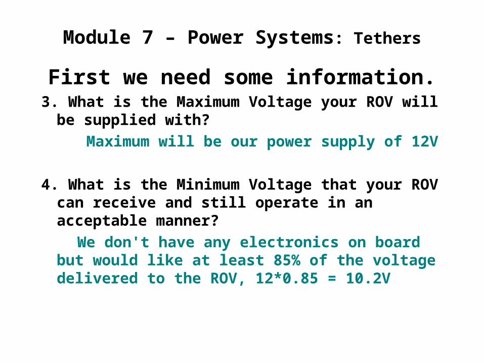
3. What is the Maximum Voltage your ROV will be supplied with?
Maximum will be our power supply of 12V
4. What is the Minimum Voltage that your ROV can receive and still operate in an acceptable manner?
We don't have any electronics on board but would like at least 85% of the voltage delivered to the ROV, 12*0.85 = 10.2V

Module 7 – Power Systems: Tethers
Now we have all our information.
We want to design our tether for maximum flexibility and with a minimum voltage drop of 1.8 volts (12v – 10.2v = 1.8v)
But what is this voltage drop stuff?
Module 7 – Power Systems: Tethers
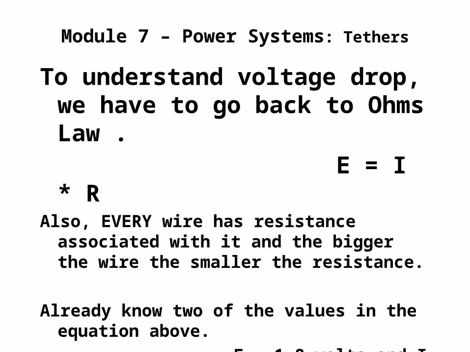
To understand voltage drop, we have to go back to Ohms Law .
E = I * RAlso, EVERY wire has resistance
associated with it and the bigger the wire the smaller the resistance.
Already know two of the values in the equation above.
E = 1.8 volts and I = 9 amps
Module 7 – Power Systems: Tethers
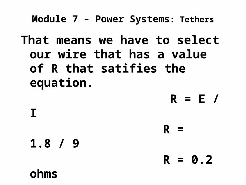
That means we have to select our wire that has a value of R that satifies the equation.
R = E / I R = 1.8 / 9 R = 0.2 ohms
OK, But where do these ohms come from in the wire? I thought wire didn't have any resistance.
Module 7 – Power Systems: Tethers
Every wire has resistance. How much depends upon material, temperature, length and diameter of that wire.
There are many conductor characteristic charts that will provide you with this information.
One such chart is at:
Wire Chart This chart is for Copper at 75C and
gives ohms per foot and sizes using American Wire Gauge (AWG)
Module 7 – Power Systems: Tethers
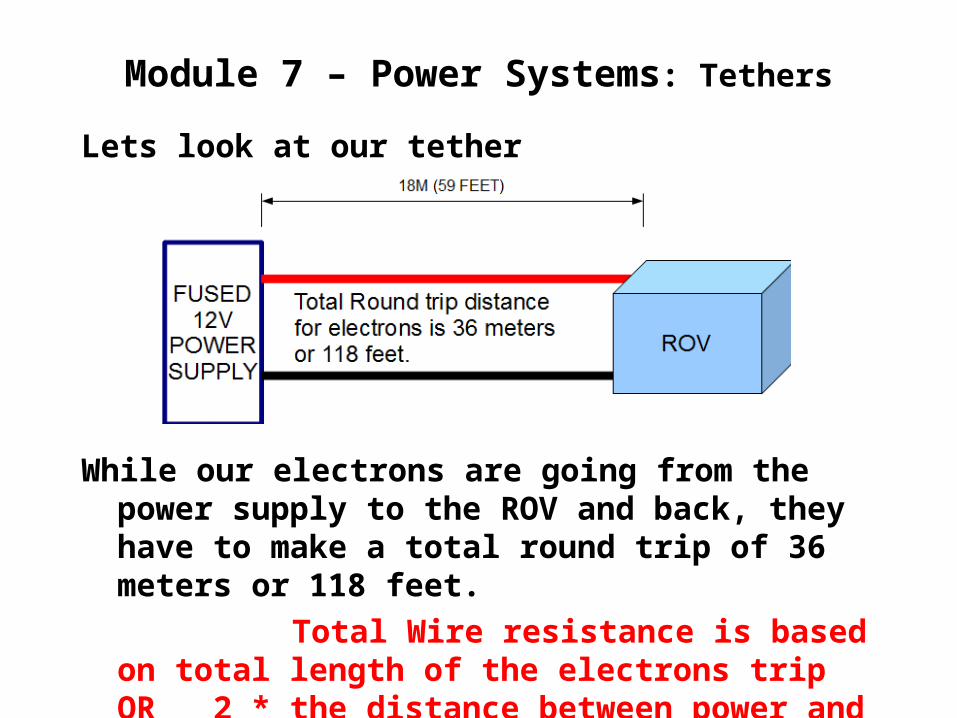
Lets look at our tether
While our electrons are going from the power supply to the ROV and back, they have to make a total round trip of 36 meters or 118 feet.
Total Wire resistance is based on total length of the electrons trip OR 2 * the distance between power and load. (supply and ROV)
Module 7 – Power Systems: Tethers
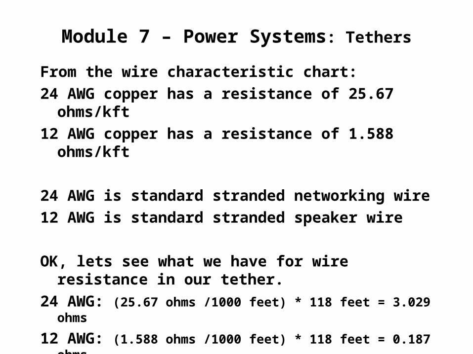
From the wire characteristic chart:24 AWG copper has a resistance of 25.67
ohms/kft12 AWG copper has a resistance of 1.588
ohms/kft
24 AWG is standard stranded networking wire
12 AWG is standard stranded speaker wire
OK, lets see what we have for wire resistance in our tether.
24 AWG: (25.67 ohms /1000 feet) * 118 feet = 3.029 ohms
12 AWG: (1.588 ohms /1000 feet) * 118 feet = 0.187 ohms
What resistance did we need?
While our electrons are going from the power supply to the ROV and back, they have to make a total round trip of 36 meters or 118 feet.
Total Wire resistance is based on distance
Module 7 – Power Systems: Tethers
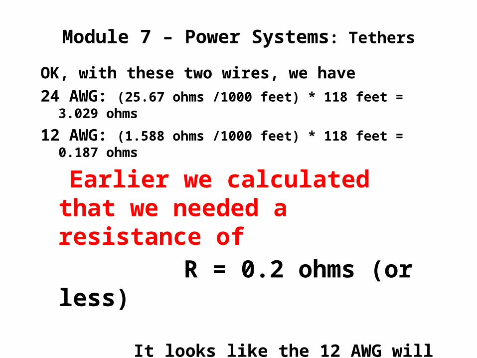
OK, with these two wires, we have24 AWG: (25.67 ohms /1000 feet) * 118 feet =
3.029 ohms
12 AWG: (1.588 ohms /1000 feet) * 118 feet = 0.187 ohms
Earlier we calculated that we needed a resistance of
R = 0.2 ohms (or less)
It looks like the 12 AWG will just work!
But... Can we make the tether
more flexible?
Module 7 – Power Systems: Tethers
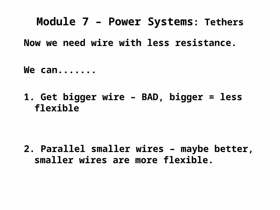
Now we need wire with less resistance.
We can.......
1. Get bigger wire – BAD, bigger = less flexible
2. Parallel smaller wires – maybe better, smaller wires are more flexible.
Module 7 – Power Systems: Tethers
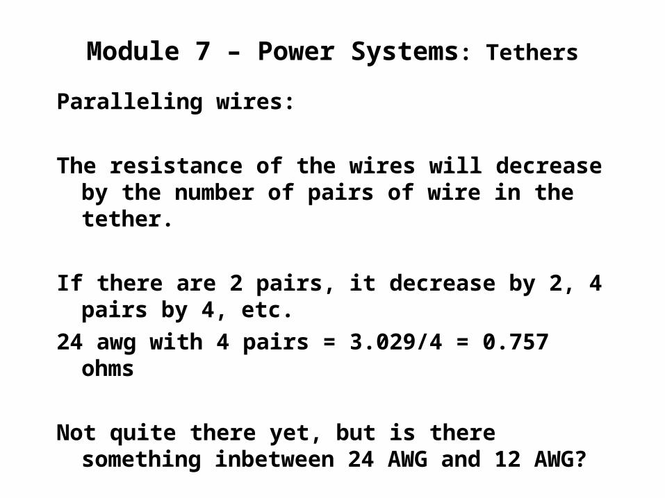
Paralleling wires:
The resistance of the wires will decrease by the number of pairs of wire in the tether.
If there are 2 pairs, it decrease by 2, 4 pairs by 4, etc.
24 awg with 4 pairs = 3.029/4 = 0.757 ohms
Not quite there yet, but is there something inbetween 24 AWG and 12 AWG?
...
Module 7 – Power Systems: Tethers
Is that the best you can do?By trying different combinations of wire
sizes and number of pairs, you can come up with a combination that will meet the original criteria of 0.2 ohms.
Exercise:Go to the Voltage Drop Calculator and see if
you can come up with a 4 pair combination of wire sizes that equal to 0.2 ohms and has a voltage at the ROV of 10.2 volts.
NOTE: The calculator uses distance from source to load, not total length, so use 18m or 59 feet
...
Module 7 – Power Systems: Tethers
WELL???What did you come up with?
You should have settled on four pairs of 18AWG in parallel for your tether and a voltage at the ROV of 10.3 Volts.
How did you do?
Module 7 – Power Systems: Tethers
Additional study material can be found on YouTube by searching for
Voltage Drop Tutorial
Have Fun!