module 4.0: gas centrifuge · module 4.0: gas centrifuge introduction welcome to module 4.0 of the...
TRANSCRIPT

MODULE 4.0: GAS CENTRIFUGE
Introduction Welcome to Module 4.0 of the Uranium Enrichment ProcessesDirected Self-Study Course! This is the fourth of seven modulesavailable in this self-study course. The purpose of this module is toassist the trainee in describing the general principle of the gascentrifuge technology and general facility and component layout,identifying the uses of the centrifuge process in industry and theproduction amounts of enriched uranium, and identifying the hazardsand safety concerns for the process, including major incidents. Thisself-study module is designed to assist you in accomplishing thelearning objectives listed at the beginning of the module. The modulehas self-check questions and an activity to help you assess yourunderstanding of the concepts presented in the module.
Before You Begin It is recommended that you have access to the following materials:
9 Trainee Guide
Complete the following prerequisite:
9 Module 1.0 Introduction to Uranium Enrichment
How to CompleteThis Module
1. Review the learning objectives.2. Read each section within the module in sequential order.3. Complete the self-check questions and activities within this
module.4. Check off the tracking form as you complete the self-check
questions and/or activity within the module.5. Contact your administrator as prompted for a progress review
meeting.6. Contact your administrator as prompted for any additional
materials and/or specific assignments.7. Complete all assignments related to this module. If no other
materials or assignments are given to you by your administrator,you have completed this module.
8. Ensure that you and your administrator have dated and initialedyour progress on the tracking form.
9. Go to the next assigned module.
Module 4.0: Gas Centrifuge
USNRC Technical Training Center 9/08 (Rev 3)Uranium Enrichment Processes i Directed Self Study
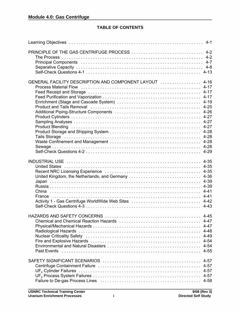
TABLE OF CONTENTS
Learning Objectives . . . . . . . . . . . . . . . . . . . . . . . . . . . . . . . . . . . . . . . . . . . . . . . . . . . . . . . . 4-1
PRINCIPLE OF THE GAS CENTRIFUGE PROCESS . . . . . . . . . . . . . . . . . . . . . . . . . . . . . . 4-2The Process . . . . . . . . . . . . . . . . . . . . . . . . . . . . . . . . . . . . . . . . . . . . . . . . . . . . . . . . . . . 4-2Principal Components . . . . . . . . . . . . . . . . . . . . . . . . . . . . . . . . . . . . . . . . . . . . . . . . . . . 4-7Separative Capacity . . . . . . . . . . . . . . . . . . . . . . . . . . . . . . . . . . . . . . . . . . . . . . . . . . . . . 4-8Self-Check Questions 4-1 . . . . . . . . . . . . . . . . . . . . . . . . . . . . . . . . . . . . . . . . . . . . . . . . 4-13
GENERAL FACILITY DESCRIPTION AND COMPONENT LAYOUT . . . . . . . . . . . . . . . . . 4-16Process Material Flow . . . . . . . . . . . . . . . . . . . . . . . . . . . . . . . . . . . . . . . . . . . . . . . . . . 4-17Feed Receipt and Storage . . . . . . . . . . . . . . . . . . . . . . . . . . . . . . . . . . . . . . . . . . . . . . . 4-17Feed Purification and Vaporization . . . . . . . . . . . . . . . . . . . . . . . . . . . . . . . . . . . . . . . . . 4-17Enrichment (Stage and Cascade System) . . . . . . . . . . . . . . . . . . . . . . . . . . . . . . . . . . . 4-19Product and Tails Removal . . . . . . . . . . . . . . . . . . . . . . . . . . . . . . . . . . . . . . . . . . . . . . 4-25Additional Piping-Structure Components . . . . . . . . . . . . . . . . . . . . . . . . . . . . . . . . . . . . 4-26Product Cylinders . . . . . . . . . . . . . . . . . . . . . . . . . . . . . . . . . . . . . . . . . . . . . . . . . . . . . . 4-27Sampling Analyses . . . . . . . . . . . . . . . . . . . . . . . . . . . . . . . . . . . . . . . . . . . . . . . . . . . . . 4-27Product Blending . . . . . . . . . . . . . . . . . . . . . . . . . . . . . . . . . . . . . . . . . . . . . . . . . . . . . . 4-27Product Storage and Shipping System . . . . . . . . . . . . . . . . . . . . . . . . . . . . . . . . . . . . . . 4-28Tails Storage . . . . . . . . . . . . . . . . . . . . . . . . . . . . . . . . . . . . . . . . . . . . . . . . . . . . . . . . . 4-28Waste Confinement and Management . . . . . . . . . . . . . . . . . . . . . . . . . . . . . . . . . . . . . . 4-28Sewage . . . . . . . . . . . . . . . . . . . . . . . . . . . . . . . . . . . . . . . . . . . . . . . . . . . . . . . . . . . . . . 4-28Self-Check Questions 4-2 . . . . . . . . . . . . . . . . . . . . . . . . . . . . . . . . . . . . . . . . . . . . . . . . 4-29
INDUSTRIAL USE . . . . . . . . . . . . . . . . . . . . . . . . . . . . . . . . . . . . . . . . . . . . . . . . . . . . . . . . 4-35United States . . . . . . . . . . . . . . . . . . . . . . . . . . . . . . . . . . . . . . . . . . . . . . . . . . . . . . . . . 4-35Recent NRC Licensing Experience . . . . . . . . . . . . . . . . . . . . . . . . . . . . . . . . . . . . . . . . 4-35United Kingdom, the Netherlands, and Germany . . . . . . . . . . . . . . . . . . . . . . . . . . . . . . 4-36Japan . . . . . . . . . . . . . . . . . . . . . . . . . . . . . . . . . . . . . . . . . . . . . . . . . . . . . . . . . . . . . . . 4-39Russia . . . . . . . . . . . . . . . . . . . . . . . . . . . . . . . . . . . . . . . . . . . . . . . . . . . . . . . . . . . . . . . 4-39China . . . . . . . . . . . . . . . . . . . . . . . . . . . . . . . . . . . . . . . . . . . . . . . . . . . . . . . . . . . . . . . 4-41France . . . . . . . . . . . . . . . . . . . . . . . . . . . . . . . . . . . . . . . . . . . . . . . . . . . . . . . . . . . . . . 4-41Activity 1 - Gas Centrifuge WorldWide Web Sites . . . . . . . . . . . . . . . . . . . . . . . . . . . . . 4-42Self-Check Questions 4-3 . . . . . . . . . . . . . . . . . . . . . . . . . . . . . . . . . . . . . . . . . . . . . . . . 4-43
HAZARDS AND SAFETY CONCERNS . . . . . . . . . . . . . . . . . . . . . . . . . . . . . . . . . . . . . . . . 4-45Chemical and Chemical Reaction Hazards . . . . . . . . . . . . . . . . . . . . . . . . . . . . . . . . . . 4-47Physical/Mechanical Hazards . . . . . . . . . . . . . . . . . . . . . . . . . . . . . . . . . . . . . . . . . . . . . 4-47Radiological Hazards . . . . . . . . . . . . . . . . . . . . . . . . . . . . . . . . . . . . . . . . . . . . . . . . . . . 4-48Nuclear Criticality Safety . . . . . . . . . . . . . . . . . . . . . . . . . . . . . . . . . . . . . . . . . . . . . . . . 4-49Fire and Explosive Hazards . . . . . . . . . . . . . . . . . . . . . . . . . . . . . . . . . . . . . . . . . . . . . . 4-54Environmental and Natural Disasters . . . . . . . . . . . . . . . . . . . . . . . . . . . . . . . . . . . . . . . 4-54Past Events . . . . . . . . . . . . . . . . . . . . . . . . . . . . . . . . . . . . . . . . . . . . . . . . . . . . . . . . . . 4-55
SAFETY SIGNIFICANT SCENARIOS . . . . . . . . . . . . . . . . . . . . . . . . . . . . . . . . . . . . . . . . . 4-57Centrifuge Containment Failure . . . . . . . . . . . . . . . . . . . . . . . . . . . . . . . . . . . . . . . . . . . 4-57UF6 Cylinder Failures . . . . . . . . . . . . . . . . . . . . . . . . . . . . . . . . . . . . . . . . . . . . . . . . . . . 4-57UF6 Process System Failures . . . . . . . . . . . . . . . . . . . . . . . . . . . . . . . . . . . . . . . . . . . . . 4-57Failure to De-gas Process Lines . . . . . . . . . . . . . . . . . . . . . . . . . . . . . . . . . . . . . . . . . . 4-58
Module 4.0: Gas Centrifuge
USNRC Technical Training Center 9/08 (Rev 3)Uranium Enrichment Processes ii Directed Self Study
Flexible Pipe Leak in Desublimer Transfer . . . . . . . . . . . . . . . . . . . . . . . . . . . . . . . . . . . 4-58Self-Check Questions 4-4 . . . . . . . . . . . . . . . . . . . . . . . . . . . . . . . . . . . . . . . . . . . . . . . . 4-59
CASE STUDY 1: CLAIBORNE ENRICHMENT CENTER . . . . . . . . . . . . . . . . . . . . . . . . . . 4-63Overview . . . . . . . . . . . . . . . . . . . . . . . . . . . . . . . . . . . . . . . . . . . . . . . . . . . . . . . . . . . . . 4-63Site Location and Description . . . . . . . . . . . . . . . . . . . . . . . . . . . . . . . . . . . . . . . . . . . . . 4-64Building Description . . . . . . . . . . . . . . . . . . . . . . . . . . . . . . . . . . . . . . . . . . . . . . . . . . . . 4-65Process Description . . . . . . . . . . . . . . . . . . . . . . . . . . . . . . . . . . . . . . . . . . . . . . . . . . . . 4-66Depleted Uranium and Wastes . . . . . . . . . . . . . . . . . . . . . . . . . . . . . . . . . . . . . . . . . . . . 4-67Safety . . . . . . . . . . . . . . . . . . . . . . . . . . . . . . . . . . . . . . . . . . . . . . . . . . . . . . . . . . . . . . . 4-67Staff Assessment . . . . . . . . . . . . . . . . . . . . . . . . . . . . . . . . . . . . . . . . . . . . . . . . . . . . . . 4-68Licensing/Status . . . . . . . . . . . . . . . . . . . . . . . . . . . . . . . . . . . . . . . . . . . . . . . . . . . . . . . 4-68
CASE STUDY 2: NATIONAL ENRICHMENT FACILITY . . . . . . . . . . . . . . . . . . . . . . . . . . . 4-69Overview . . . . . . . . . . . . . . . . . . . . . . . . . . . . . . . . . . . . . . . . . . . . . . . . . . . . . . . . . . . . . 4-69Site Location and Description . . . . . . . . . . . . . . . . . . . . . . . . . . . . . . . . . . . . . . . . . . . . . 4-69Building Description . . . . . . . . . . . . . . . . . . . . . . . . . . . . . . . . . . . . . . . . . . . . . . . . . . . . 4-71Process Description . . . . . . . . . . . . . . . . . . . . . . . . . . . . . . . . . . . . . . . . . . . . . . . . . . . . 4-72Depleted Uranium and Wastes . . . . . . . . . . . . . . . . . . . . . . . . . . . . . . . . . . . . . . . . . . . . 4-74Safety . . . . . . . . . . . . . . . . . . . . . . . . . . . . . . . . . . . . . . . . . . . . . . . . . . . . . . . . . . . . . . . 4-76Staff Assessment . . . . . . . . . . . . . . . . . . . . . . . . . . . . . . . . . . . . . . . . . . . . . . . . . . . . . . 4-78Licensing/Status . . . . . . . . . . . . . . . . . . . . . . . . . . . . . . . . . . . . . . . . . . . . . . . . . . . . . . . 4-78
CASE STUDY 3: AMERICAN CENTRIFUGE PLANT . . . . . . . . . . . . . . . . . . . . . . . . . . . . . 4-79Overview . . . . . . . . . . . . . . . . . . . . . . . . . . . . . . . . . . . . . . . . . . . . . . . . . . . . . . . . . . . . . 4-79Site Location and Description . . . . . . . . . . . . . . . . . . . . . . . . . . . . . . . . . . . . . . . . . . . . . 4-80Building Description . . . . . . . . . . . . . . . . . . . . . . . . . . . . . . . . . . . . . . . . . . . . . . . . . . . . 4-80Process Description . . . . . . . . . . . . . . . . . . . . . . . . . . . . . . . . . . . . . . . . . . . . . . . . . . . . 4-83Depleted Uranium and Wastes . . . . . . . . . . . . . . . . . . . . . . . . . . . . . . . . . . . . . . . . . . . . 4-87Safety . . . . . . . . . . . . . . . . . . . . . . . . . . . . . . . . . . . . . . . . . . . . . . . . . . . . . . . . . . . . . . . 4-91Staff Assessment . . . . . . . . . . . . . . . . . . . . . . . . . . . . . . . . . . . . . . . . . . . . . . . . . . . . . . 4-92Licensing/Status . . . . . . . . . . . . . . . . . . . . . . . . . . . . . . . . . . . . . . . . . . . . . . . . . . . . . . . 4-93Self-Check Questions 4-5 . . . . . . . . . . . . . . . . . . . . . . . . . . . . . . . . . . . . . . . . . . . . . . . . 4-94
Progress Review Meeting Form . . . . . . . . . . . . . . . . . . . . . . . . . . . . . . . . . . . . . . . . . . . . . . 4-97
MODULE SUMMARY . . . . . . . . . . . . . . . . . . . . . . . . . . . . . . . . . . . . . . . . . . . . . . . . . . . . . . 4-99
LIST OF FIGURES
Figure 4-1. Idealized Schematic of Gas Centrifuge . . . . . . . . . . . . . . . . . . . . . . . . . . . . . . . . 4-3Figure 4-2. UF6 Phase Diagram . . . . . . . . . . . . . . . . . . . . . . . . . . . . . . . . . . . . . . . . . . . . . . 4-4Figure 4-3. Schematic of Gas Centrifuge Cascade Arrangement . . . . . . . . . . . . . . . . . . . . . 4-5Figure 4-4. Gas Centrifuge Schematic . . . . . . . . . . . . . . . . . . . . . . . . . . . . . . . . . . . . . . . . . 4-6Figure 4-5. Natural Harmonics . . . . . . . . . . . . . . . . . . . . . . . . . . . . . . . . . . . . . . . . . . . . . . 4-10Figure 4-6. Block Diagram of Proposed Claiborne Enrichment Center (CEC) Centrifuge . 4-16Figure 4-7. Centrifuge Stage Arrangement . . . . . . . . . . . . . . . . . . . . . . . . . . . . . . . . . . . . . 4-20Figure 4-8. Centrifuge Cascade . . . . . . . . . . . . . . . . . . . . . . . . . . . . . . . . . . . . . . . . . . . . . 4-21Figure 4-9. Production Unit Process Piping . . . . . . . . . . . . . . . . . . . . . . . . . . . . . . . . . . . . . 4-23Figure 4-10. Parallel Arrangement of Cascades to Form Production Units . . . . . . . . . . . . . 4-24Figure 4-11. Cascade Header Piping . . . . . . . . . . . . . . . . . . . . . . . . . . . . . . . . . . . . . . . . . 4-26

Module 4.0: Gas Centrifuge
USNRC Technical Training Center 9/08 (Rev 3)Uranium Enrichment Processes iii Directed Self Study
Figure 4-12. View of an Urenco Cascade . . . . . . . . . . . . . . . . . . . . . . . . . . . . . . . . . . . . . . 4-38Figure 4-13. Block Mounted Designs . . . . . . . . . . . . . . . . . . . . . . . . . . . . . . . . . . . . . . . . . 4-38Figure 4-14. Russian GCs . . . . . . . . . . . . . . . . . . . . . . . . . . . . . . . . . . . . . . . . . . . . . . . . . . 4-40Figure 4-15. The Effect of the Assay Level Upon the Minimum Critical Mass . . . . . . . . . . . 4-50Figure 4-16. UO2 and Water Systems . . . . . . . . . . . . . . . . . . . . . . . . . . . . . . . . . . . . . . . . . 4-51Figure 4-17. The Impact of Assay Upon Critical Masses, Volumes, and Geometries . . . . . 4-52Figure 4-18. Map of Area Around Homer, LA . . . . . . . . . . . . . . . . . . . . . . . . . . . . . . . . . . . 4-64Figure 4-19. Location with Respect to Major Cities . . . . . . . . . . . . . . . . . . . . . . . . . . . . . . . 4-65Figure 4-20. Proposed Facility Location . . . . . . . . . . . . . . . . . . . . . . . . . . . . . . . . . . . . . . . 4-70Figure 4-21. Artist Representation of the Proposed Facility . . . . . . . . . . . . . . . . . . . . . . . . 4-71Figure 4-22. Existing Portsmouth Site . . . . . . . . . . . . . . . . . . . . . . . . . . . . . . . . . . . . . . . . . 4-81Figure 4-23. Proposed GC Facility at Portsmouth . . . . . . . . . . . . . . . . . . . . . . . . . . . . . . . . 4-82Figure 4-24. Top View of DOE GCs . . . . . . . . . . . . . . . . . . . . . . . . . . . . . . . . . . . . . . . . . . 4-85Figure 4-25. Side View of DOE GCs . . . . . . . . . . . . . . . . . . . . . . . . . . . . . . . . . . . . . . . . . . 4-85Figure 4-26. Machine Cooling Water (MCW) System . . . . . . . . . . . . . . . . . . . . . . . . . . . . . 4-89
LIST OF TABLES
Table 4-1. Gas Centrifuge Components and Brief Description . . . . . . . . . . . . . . . . . . . . . . . 4-7Table 4-2. Potential Significant Accidents at a GC Facility (from NUREG – 1827) . . . . . . . 4-46Table 4-3. Urenco Operating Experience with UF6 Leaks . . . . . . . . . . . . . . . . . . . . . . . . . . 4-56

Module 4.0: Gas Centrifuge
USNRC Technical Training Center 9/08 (Rev 3)Uranium Enrichment Processes Directed Self Study4-1
Learning Objectives
4.1 Upon completion of this module, you will be able to describethe gas centrifuge enrichment process.
4.1.1 Describe the principles of the gas centrifuge process.
4.1.2 Describe general facility and component layout of the gascentrifuge enrichment process.
4.1.3 Identify the uses of the gas centrifuge process in industry and the required production amounts of enriched uranium.
4.1.4 Identify the hazards and safety concerns for the gas centrifuge process, including major incidents.
4.1.5 Summarize Case Study 1: Summary of Proposed ClaiborneEnrichment Center.
4.1.6 Summarize Case Study 2: Summary of Proposed NationalEnrichment Facility.
4.1.7 Summarize Case Study 3: Summary of Proposed AmericanCentrifuge Plant.

Module 4.0: Gas Centrifuge
USNRC Technical Training Center 9/08 (Rev 3)Uranium Enrichment Processes Directed Self Study4-2
Learning Objective
When you finish this section, you will be able to:
4.1.1 Describe the principles of the gas centrifuge process.
PRINCIPLE OF THEGAS CENTRIFUGEPROCESS
The use of centrifugal fields for isotope separation was first suggestedin 1919, but efforts in this direction were unsuccessful until 1934,when J.W. Beams and coworkers at the University of Virginia applieda vacuum ultracentrifuge to the separation of chlorine isotopes. Although abandoned midway through the Manhattan Project, the gascentrifuge (GC) uranium enrichment process has been highlydeveloped and used to produce both highly enriched uranium (HEU)and low enriched uranium (LEU).
The centrifuge separation process uses the principle of centrifugalforce to create a density gradient in gaseous uranium hexafluoride(UF6) that contains components of different molecular weights. In thisuranium enrichment process, gaseous UF6 is fed into a cylindricalrotor that spins at high speed inside an evacuated casing or stator. Because the rotor spins so rapidly, centrifugal force results in the gasoccupying only a thin layer next to the rotor wall, with the gas movingat approximately the speed of the wall. Centrifugal force causes theheavier UF6 molecule containing U-238 atoms to move closer towardthe outer wall of the cylinder and the lighter UF6 molecule containingU-235 atoms toward the axis, thus partially separating the uraniumisotopes. This separation is increased by a relatively slow axialcountercurrent flow (CCF) of gas within the centrifuge thatconcentrates gas enriched in U-235 at one end and gas depleted inU-238 at the other. This flow can be driven mechanically by scoopsand baffles or thermally by heating one of the end caps. The streamthat is enriched in U-235 is withdrawn and fed into the next higherstage, while the depleted stream is recycled back into the next lowerstage. The principle of the countercurrent gas centrifuge is illustratedin Figure 4-1, “Idealized Schematic of Gas Centrifuge.”
The Process The renewed interest in the GC process is driven by the promise oflower cost enrichment. Enrichment cost estimated in 2007 for GCprocess was $60/SWU vs. $120/SWU or more for GDP. GCpromises:
• Larger enrichment effect per stage (>1.05 vs. 1.004 for GDP)
• Smaller facilites than GDPs
• Reduced uranium inventories in cascades
• Better energy efficiencies

Module 4.0: Gas Centrifuge
USNRC Technical Training Center 9/08 (Rev 3)Uranium Enrichment Processes Directed Self Study4-3
Note:- Axial connections- Rotor in casing (stator)- Vacuum pull on stator- CCF effect
- heat bottom- cool top
- Bearings
• More rapidly achieves equilibrium/steady-state (< 1 day vs.“weeks” GDP)
Figure 4-1. Idealized Schematic of Gas Centrifuge
The main operations and steps of the gas centrifuge process aresimilar to the steps in the gaseous diffusion process:
- Feed cylinder receipt and storage
- Cylinder purification and vaporization/feed to the cascade
- GC enrichment cascade
- DU tails withdrawal and storage
- Product withdrawal
- sampling (usually the product cylinders)
- Product storage and shipping
- Associated emissions, effluent, and waste managementsystems
As shown in Figure 4-2, GC facilities generally operate at lowertemperatures and pressures than gaseous diffusion plants, andprovide higher separation effects. Hazards are generally lower,

Module 4.0: Gas Centrifuge
USNRC Technical Training Center 9/08 (Rev 3)Uranium Enrichment Processes Directed Self Study4-4
particularly if liquid UF6 is minimized during plant operations. This canbe accomplished, for example, by using sublimation anddesublimation in the feed and withdrawal areas, and restricting liquidUF6 to the interiors of autoclaves (e.g., during sampling, and nomovement of liquefied cylinders).
Figure 4-2. UF6 Phase Diagram
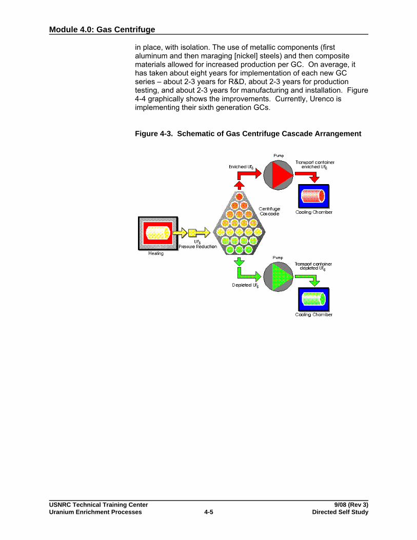
GCs achieve higher separations per machine, and thus, fewer stagesare needed to produce the desired enrichment assay. However, moreGCs/stages are needed in parallel in order to meet throughputrequirements. This combination of GCs is termed a cascade. Figure4-3 shows a schematic of a GC cascade. In general, multiplecascades are used in operating facilities. Thus, implementation of GCenrichment can be accomplished in an incremental, modular manner,allowing enrichment operations to begin before the entire plant iscompleted or to meet additional demand.
As noted, GC uranium enrichment has been around for a long time. Large scale implementation was limited by engineering and materialdifficulties, and the success of the gaseous diffusion process. However, small groups of researchers continued working on GCenrichment technology and sufficient, significant improvements weremade by the 1960s to prove the viability of the process. The U.S.teams favored larger GCs (200 and now 300+ SWU per GC) while theEuropean researchers focused on smaller machines (40-100 SWUsper GC). The larger GCs require maintenance every two years or so,while the smaller GCs are more reliable and are usually allowed to fail
Module 4.0: Gas Centrifuge
USNRC Technical Training Center 9/08 (Rev 3)Uranium Enrichment Processes Directed Self Study4-5
in place, with isolation. The use of metallic components (firstaluminum and then maraging [nickel] steels) and then compositematerials allowed for increased production per GC. On average, ithas taken about eight years for implementation of each new GCseries – about 2-3 years for R&D, about 2-3 years for productiontesting, and about 2-3 years for manufacturing and installation. Figure4-4 graphically shows the improvements. Currently, Urenco isimplementing their sixth generation GCs.
Figure 4-3. Schematic of Gas Centrifuge Cascade Arrangement

Module 4.0: Gas Centrifuge
USNRC Technical Training Center 9/08 (Rev 3)Uranium Enrichment Processes Directed Self Study4-6
Figure 4-4. Gas Centrifuge Schematic
The GC must operate at rotational speeds above natural harmonics ofthe gas centrifuge, so controls must monitor vibrations and allow rapidtraversing of rotational speeds corresponding to natural harmonics. The bearings and drives must accommodate imperfections andvibrations during acceleration and deceleration.
There are tens of thousands of GCs in a plant. GCs do "break." Reliability and isolation after failure are important issues in theprocess. The GC design must accommodate repair and replacementand ES&H standards must be maintained throughout the process. The current approach to NRC regulation is to use revised Part 70 andSubpart H as guidance.
See Section 4.1.3, “Industrial Use,” for more information on GCtechnology world-wide.
Module 4.0: Gas Centrifuge
USNRC Technical Training Center 9/08 (Rev 3)Uranium Enrichment Processes Directed Self Study4-7
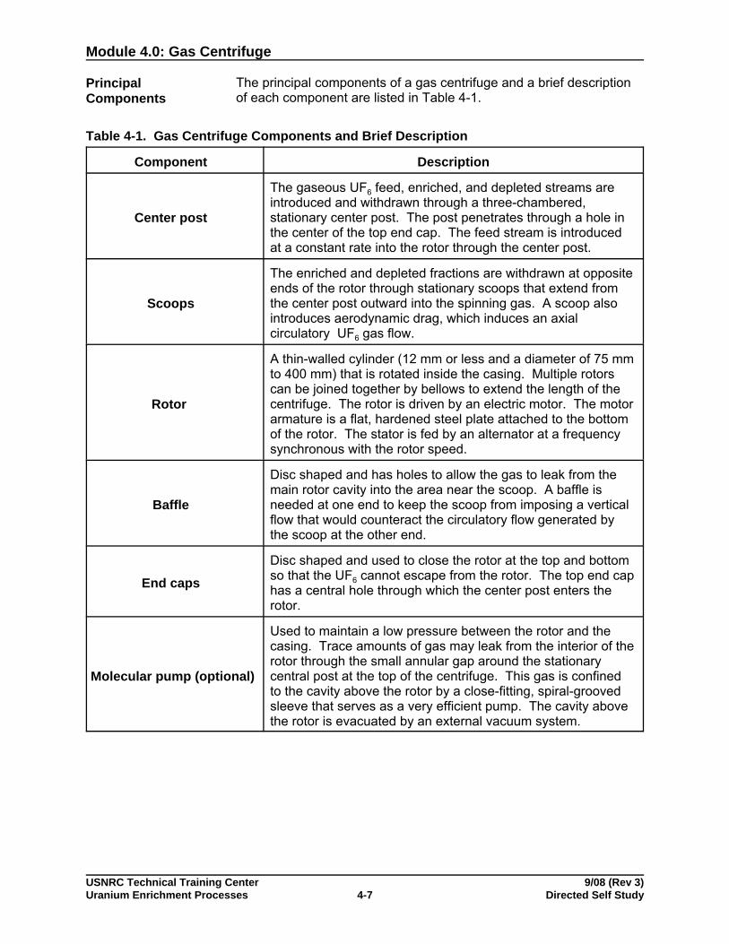
PrincipalComponents
The principal components of a gas centrifuge and a brief descriptionof each component are listed in Table 4-1.
Table 4-1. Gas Centrifuge Components and Brief Description
Component Description
Center post
The gaseous UF6 feed, enriched, and depleted streams areintroduced and withdrawn through a three-chambered, stationary center post. The post penetrates through a hole inthe center of the top end cap. The feed stream is introducedat a constant rate into the rotor through the center post.
Scoops
The enriched and depleted fractions are withdrawn at oppositeends of the rotor through stationary scoops that extend fromthe center post outward into the spinning gas. A scoop alsointroduces aerodynamic drag, which induces an axialcirculatory UF6 gas flow.
Rotor
A thin-walled cylinder (12 mm or less and a diameter of 75 mmto 400 mm) that is rotated inside the casing. Multiple rotorscan be joined together by bellows to extend the length of thecentrifuge. The rotor is driven by an electric motor. The motor armature is a flat, hardened steel plate attached to the bottomof the rotor. The stator is fed by an alternator at a frequencysynchronous with the rotor speed.
Baffle
Disc shaped and has holes to allow the gas to leak from themain rotor cavity into the area near the scoop. A baffle isneeded at one end to keep the scoop from imposing a verticalflow that would counteract the circulatory flow generated bythe scoop at the other end.
End caps
Disc shaped and used to close the rotor at the top and bottomso that the UF6 cannot escape from the rotor. The top end caphas a central hole through which the center post enters therotor.
Molecular pump (optional)
Used to maintain a low pressure between the rotor and thecasing. Trace amounts of gas may leak from the interior of therotor through the small annular gap around the stationarycentral post at the top of the centrifuge. This gas is confinedto the cavity above the rotor by a close-fitting, spiral-groovedsleeve that serves as a very efficient pump. The cavity abovethe rotor is evacuated by an external vacuum system.
Module 4.0: Gas Centrifuge
Table 4-1. Gas Centrifuge Components and Brief Description
Component Description
USNRC Technical Training Center 9/08 (Rev 3)Uranium Enrichment Processes Directed Self Study4-8
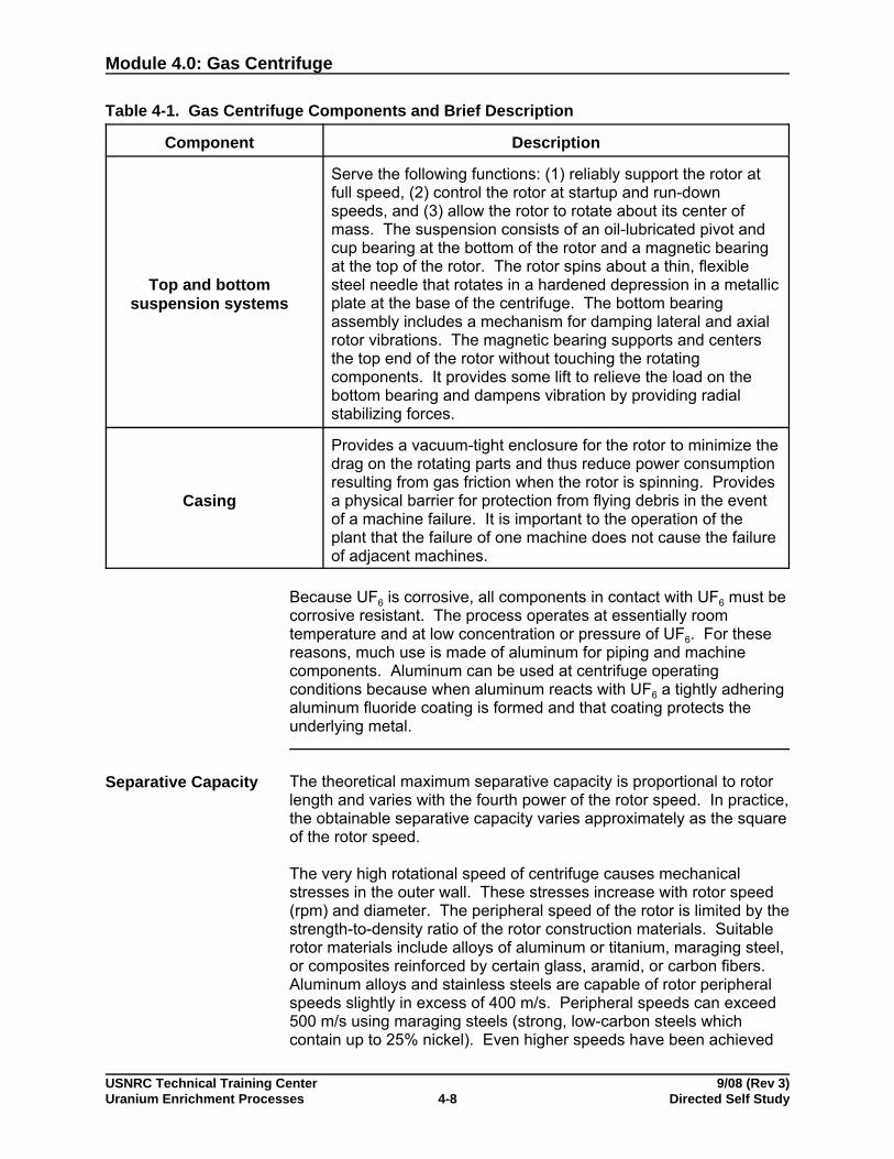
Top and bottomsuspension systems
Serve the following functions: (1) reliably support the rotor atfull speed, (2) control the rotor at startup and run-downspeeds, and (3) allow the rotor to rotate about its center ofmass. The suspension consists of an oil-lubricated pivot andcup bearing at the bottom of the rotor and a magnetic bearingat the top of the rotor. The rotor spins about a thin, flexiblesteel needle that rotates in a hardened depression in a metallicplate at the base of the centrifuge. The bottom bearingassembly includes a mechanism for damping lateral and axialrotor vibrations. The magnetic bearing supports and centersthe top end of the rotor without touching the rotatingcomponents. It provides some lift to relieve the load on thebottom bearing and dampens vibration by providing radialstabilizing forces.
Casing
Provides a vacuum-tight enclosure for the rotor to minimize thedrag on the rotating parts and thus reduce power consumptionresulting from gas friction when the rotor is spinning. Providesa physical barrier for protection from flying debris in the eventof a machine failure. It is important to the operation of theplant that the failure of one machine does not cause the failureof adjacent machines.
Because UF6 is corrosive, all components in contact with UF6 must becorrosive resistant. The process operates at essentially roomtemperature and at low concentration or pressure of UF6. For thesereasons, much use is made of aluminum for piping and machinecomponents. Aluminum can be used at centrifuge operatingconditions because when aluminum reacts with UF6 a tightly adheringaluminum fluoride coating is formed and that coating protects theunderlying metal.
Separative Capacity The theoretical maximum separative capacity is proportional to rotorlength and varies with the fourth power of the rotor speed. In practice,the obtainable separative capacity varies approximately as the squareof the rotor speed.
The very high rotational speed of centrifuge causes mechanicalstresses in the outer wall. These stresses increase with rotor speed(rpm) and diameter. The peripheral speed of the rotor is limited by thestrength-to-density ratio of the rotor construction materials. Suitablerotor materials include alloys of aluminum or titanium, maraging steel,or composites reinforced by certain glass, aramid, or carbon fibers. Aluminum alloys and stainless steels are capable of rotor peripheralspeeds slightly in excess of 400 m/s. Peripheral speeds can exceed500 m/s using maraging steels (strong, low-carbon steels whichcontain up to 25% nickel). Even higher speeds have been achieved

Module 4.0: Gas Centrifuge
USNRC Technical Training Center 9/08 (Rev 3)Uranium Enrichment Processes Directed Self Study4-9
using glass-fiber and carbon-fiber composites. Consequently,composite technology is preferred for large scale commercial plants. The choice of materials suitable for centrifuge components is limitedby the corrosive nature of the UF6 process gas.
The length of the rotor is limited by rotor dynamics. The rotor must becarefully balanced and damped to prevent wobbling and vibration. This is especially critical to avoid early failure of the bearing andsuspension systems. Because perfect balance is not possible, thesuspension system must be capable of damping some amount ofvibration. Major factors affecting the rotor dynamics include thestraightness of the rotor, the uniformity of the wall, and the dampingcharacteristics of the bottom bearing system.
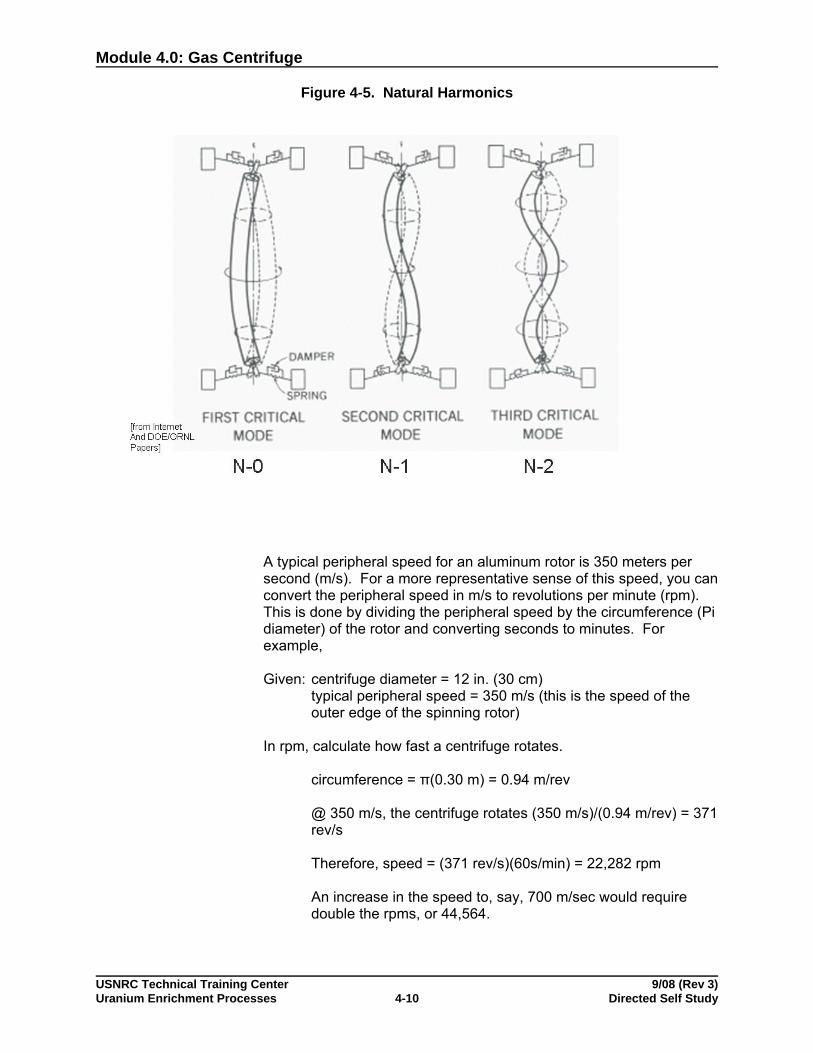
Another concern with centrifuges that have a large length to diameterratio is the problem of achieving operating speeds after shutdowns,say, caused by power interruptions. Centrifuges have naturalharmonic resonance frequencies that can result in standing wavepatterns, often called critical modes. These induce additionalvibrations and stresses on GC rotors, and often result in failures. Theproblem is more pronounced for longer and higher speed machines,and smaller diameters. Figure 4-5 illustrates several mode patterns,each one of which corresponds to a certain speed for the materialsand geometries involved. Attempted operation in a critical modewould likely result in excessive vibration and wall stresses, leading tomechanical failure of the GC rotor. Operation at higher rotationalspeeds to achieve higher separation or SWU capacity often requiresexceeding one or more critical modes. These are termed supercriticalGCs. Therefore, during rotor acceleration for resuming operationsafter a shutdown, the rotor must rapidly traverse these critical modes,which requires special motor controls, bearings, and dampeningsystems.
Module 4.0: Gas Centrifuge
USNRC Technical Training Center 9/08 (Rev 3)Uranium Enrichment Processes Directed Self Study4-10
Figure 4-5. Natural Harmonics
A typical peripheral speed for an aluminum rotor is 350 meters persecond (m/s). For a more representative sense of this speed, you canconvert the peripheral speed in m/s to revolutions per minute (rpm). This is done by dividing the peripheral speed by the circumference (Pidiameter) of the rotor and converting seconds to minutes. Forexample,
Given: centrifuge diameter = 12 in. (30 cm)typical peripheral speed = 350 m/s (this is the speed of theouter edge of the spinning rotor)
In rpm, calculate how fast a centrifuge rotates.
circumference = π(0.30 m) = 0.94 m/rev
@ 350 m/s, the centrifuge rotates (350 m/s)/(0.94 m/rev) = 371rev/s
Therefore, speed = (371 rev/s)(60s/min) = 22,282 rpm
An increase in the speed to, say, 700 m/sec would requiredouble the rpms, or 44,564.

Module 4.0: Gas Centrifuge
USNRC Technical Training Center 9/08 (Rev 3)Uranium Enrichment Processes Directed Self Study4-11
One of the key components of a gas centrifuge enrichment plant is thepower supply (frequency converter) for the gas centrifuge machines. The power supply must accept alternating current (ac) input at the 50-or 60-Hz line frequency available from the electric power grid andprovide an ac output at a much higher frequency (typically 600 Hz ormore). The high-frequency output from the frequency converter is fedto the high-speed gas centrifuge drive motors (the speed of an acmotor is proportional to the frequency of the supplied current). Thecentrifuge power supplies must operate at high efficiency, provide lowharmonic distortion, and provide precise control of the outputfrequency.
The casing is needed both to maintain a vacuum and to contain therapidly spinning components in the event of a failure. A gascentrifuge unit operating at high speeds could generate flying piecesof equipment and material as a result of the destruction of the rotorand other spinning components. If the shrapnel from a singlecentrifuge failure is not contained, a "domino effect" may result anddestroy adjacent centrifuges. A single casing may enclose one orseveral rotors.
Many gas centrifuges are needed in commercial facilities – typicalnumbers exceed 10,000 per plant. Consequently, capacity permachine (SWU), reliability, and detection/isolation (after failure or formaintenance) become very important. Reliability can be measuredseveral different ways; the two most applicable to GCs are mean timebetween failures (MTBF) and failure rate (as a number or percentageper year). Mechanical equipment in the chemical industries havetypical MTBFs of 3-10 years (this is why annual shutdowns orpreventative maintenance are performed). Using 10,000 GCs as abasis, this implies half the facility’s capacity would be lost in ten yearsor less – potentially several a day (linear basis) – without maintenanceand/or replacements; the latter are difficult to do in the confines of acommercial GC plant. Urenco has taken the approach of using veryreliable small GCs, without routine repair or replacement, and hasstated failure rates of less than 0.5%/yr. and, more recently, less than0.1%/yr. A failure rate of 0.5%/yr. corresponds to 50 GCs/yr. or 1,500GCs over a 30 year period (a typical planned operational lifetime forGC plants) for a 10,000 GC plant, a loss of 15% of capacity. A failurerate of 0.1%/yr. would correlate with 10 GCs failing per year or 300over 30 years, a more manageable loss of 3% of capacity. Urencohas stated additional GCs are installed in its facilities to account forthese failures. Urenco had a high percentage of GCs installed in itsfacilities in the 1970s that are still operating today. Urenco includesadditional, extra GCs in its design to accommodate the smallproduction loss from failed centrifuges.
The larger GCs are also very reliable, although reliability informationhas not been published. However, the operational philosophy is toperform routine, preventative maintenance on a schedule, such asevery two to five years or so. Consequently, the facility designsincorporate this planned maintenance with additional cranes,

Module 4.0: Gas Centrifuge
USNRC Technical Training Center 9/08 (Rev 3)Uranium Enrichment Processes Directed Self Study4-12
access/spacing, valves, transporting containers, maintenancefacilities, and ES&H requirements. The intent is to make this assimple as changing a light bulb. A two year maintenance intervalcorresponds to about 15 GCs/day while a five year interval givesabout 6 GCs/day, for a 10,000 GC facility. The larger GCs have notbeen operated as long as the smaller designs and have not beenoperated commercially.
The physical size and separative capacity of gas centrifuges vary. European and Japanese centrifuges are relatively small (25centimeters in diameter and 2 meters to 4 meters long) and haveseparative capacities in the range of 5 SWU/year to 100 SWU/year. The U.S.-designed centrifuges were substantially larger and hadseparative capacities up to 10 times larger.
Enrichment theories show that a higher degree of U-235 enrichmentcan be obtained from a single unit gas centrifuge than from a singleunit gaseous diffusion barrier. The separation factor available from asingle centrifuge is about 1.05 to 1.2 as compared to 1.004 for agaseous diffusion stage. However, the throughput rate of UF6 thatcan be processed by a single centrifuge is very small compared to agaseous diffusion stage. Although they differ in the type and functionof the enrichment equipment used to process the UF6, gas centrifugeand gaseous diffusion enrichment plants use similar process,equipment, and safety systems for UF6 feed and withdrawal of productand tails. However, most new GC facility plants and designs minimizethe use of liquid UF6. Feed is sublimed, while tails and products arewithdrawn by desublimation.
The electrical consumption of a gas centrifuge facility is much lessthan that of a gaseous diffusion plant of the same SWU capacity: atypical GC plant consumes less than 5% of the electricity used by anequivalent sized GDP. Consequently, a centrifuge plant will not havethe easily identified electrical and cooling systems typically requiredby a gaseous diffusion plant.

Module 4.0: Gas Centrifuge
USNRC Technical Training Center 9/08 (Rev 3)Uranium Enrichment Processes Directed Self Study4-13
Self-Check Questions 4-1
Complete the following questions. Answers are located in the answer key section of theTrainee Guide.
1. What is the feed material for the gas centrifuge enrichment process?
2. The centrifuge separation process uses the principle of centrifugal force to create what?
3. What happens to U-235 and U-238 atoms in the centrifuge process?
4. What increases separation?
5. What are the major components of a gas centrifuge?
6. How and through what component is the feed stream introduced into the rotor?

Module 4.0: Gas Centrifuge
USNRC Technical Training Center 9/08 (Rev 3)Uranium Enrichment Processes Directed Self Study4-14
7. Why and how can multiple rotors be joined together?
8. How is a rotor driven?
9. What is the purpose of a baffle?
10. How are end caps used?
11. Why is an optional molecular pump used?
12. What are the three functions of the top and bottom suspension systems?
13. What is the purpose of the casing?

Module 4.0: Gas Centrifuge
USNRC Technical Training Center 9/08 (Rev 3)Uranium Enrichment Processes Directed Self Study4-15
14. What factors influence the separative capacity of a gas centrifuge?
15. What is limited by the strength-to-density ratio of the rotor construction materials?
16. What are some major factors that affect the rotor dynamics?
17. What concern exists with centrifuges that have a large length-to-diameter ratio?
18. One of the key components of a gas centrifuge enrichment plant is the power supply(frequency converter) for the gas centrifuge machines. How should the power supplyoperate?
19. List two differences between a gas centrifuge facility and a gaseous diffusion facility.
You have completed this section.Please check off your progress on the tracking form.
Go to the next section.
Module 4.0: Gas Centrifuge
USNRC Technical Training Center 9/08 (Rev 3)Uranium Enrichment Processes Directed Self Study4-16
Learning Objective
When you finish this section, you will be able to:
4.1.2 Describe general facility and component layout of the gas centrifuge enrichmentprocess.
GENERAL FACILITYDESCRIPTION ANDCOMPONENTLAYOUT
This section describes a generic layout for a gas centrifuge facility. The proposed Claiborne Enrichment Center centrifuge process blockdiagram illustrated in Figure 4-6 has been included to assist invisualizing steps in a gas centrifuge process.
Figure 4-6. Block Diagram of Proposed Claiborne Enrichment Center (CEC) Centrifuge

Module 4.0: Gas Centrifuge
USNRC Technical Training Center 9/08 (Rev 3)Uranium Enrichment Processes Directed Self Study4-17
Process MaterialFlow
Major nuclear material flows at a gas centrifuge enrichment facilityinclude receipt of UF6 feed material onsite, transfer of feed materialfrom UF6 cylinders to the process system, transfer of enriched anddepleted process gas to product and tails cylinders, and shipment ofproduct cylinders offsite. Minor material flows include sampletransfers to an analytical laboratory, process equipment transfers fordecontamination and repair, and waste transfers to the scrap recoveryand waste treatment areas.
Feed Receipt andStorage
Upon receipt at the enrichment plant, UF6 feed cylinders may beweighed, inspected, and liquid sampled (optional) to establish nuclearmaterials accountability values (via destructive analysis) and to verifyspecifications by the enricher and customer. The cylinders are thenplaced in a storage area. When it is time for the contents of a full feedcylinder to be fed into the process, the cylinder is moved from thestorage area to the feed area.
Feed Purificationand Vaporization
In the feed area, cylinders containing feed material are placed inautoclaves (heating stations) where they are heated to convert theUF6 from solid to gas. Light gas impurities are removed from the UF6at this time before the UF6 is introduced into the enrichment system. The UF6 is purified by venting the cylinders to remove light gasessuch as oxygen, nitrogen, and hydrogen fluoride (HF). This isaccomplished in two purification steps. The initial step is called coldpurification and involves venting the cylinder while the UF6 is solid atambient temperature. During cold purification, safety controlsautomatically disable the feed autoclave heater and preventinadvertent heating of the cylinder. The vented light gases passthrough a desublimer and chemical traps to remove uranium and HFbefore being released to a gaseous effluent vent system. Thisprovides assurance of contaminant control by filtering the vent gasesthrough cold feed high efficiency particulate air filters and activatedcarbon filters before releasing the gas to the atmosphere. Thispurification process is repeated until the desired purity is achieved.
Note: The feed and purification segment of the plant includes thefeed autoclaves, purification desublimers and cubicles, andassociated valves, piping, and controls. The primary controlsare the heater protection circuits of the autoclaves and thestate switches for the autoclave, desublimer, and purificationcubicle. A state switch is a multifunctional selector whichactivates control circuits for process elements including valvesand pumps.
The primary process control functions of the autoclave areheating and evaporating or subliming the UF6 and controllingthe flow leaving the autoclave. Control of heating rate isdetermined by monitoring the cylinder exit pressure, which isdirectly related to UF6 temperature and phase state. Flow rateof UF6 is controlled by monitoring autoclave exit line pressure,
Module 4.0: Gas Centrifuge
USNRC Technical Training Center 9/08 (Rev 3)Uranium Enrichment Processes Directed Self Study4-18
which is determined by the pressure drop across the controlvalve located inside the autoclave. Positioning of valves otherthan the autoclave exit flow control valve is determined by thestates selected on the autoclave and desublimer stateswitches. Thus, for cold purification, the autoclave stateswitch is in the cold purify position, the desublimer state switchis in the purification position, the valves leading to thecascades and the purification cubicle are closed, the inletvalve to the desublimer is open, and cold refrigerant cools thedesublimer. Similar considerations and valve positioning arealso determined for other purification and feed functions.
The new designs for GC facilities use sublimation and avoidliquid UF6. Sublimation can be performed in an autoclave oran oven.
The second step is called hot purification and involves heating theUF6 cylinder. In traditional FC facilities and designs (older Urencofacilities and the LES-1 design) the cylinder contents are liquified. The UF6 is liquified by heating the exterior of the feed cylinder with hotair within the autoclave. The temperature of air is controlled tomaintain specific pressure as the UF6 is liquified. The cylinder isagain vented to the desublimer to remove light gas contaminants thatmay have been trapped in the solid UF6. Typically, only one hotpurification cycle is performed for each cylinder. Once the desiredpurity is reached, the feed cylinder vent valve is closed and thecylinder is maintained in a standby mode with the UF6 still in the liquidstate.
New GC facilities and designs heat the cylinder to about 125"F andsublime the contents for hot purification and subsequent UF6 feeding.
After feed purification, a valve in the line from the cylinder to thecascade is opened and gaseous UF6 flows from the cylinder to thecascade. The UF6 feed cylinder temperature and pressure arecontrolled during the feed cycle. The UF6 gas is above atmosphericpressure when it leaves the cylinder, but is passed through a motor-operated pressure reduction valve located inside the autoclave. When the contents of the feed cylinder are nearly removed, anotherautoclave is brought on-line to supplement the decreasing flow of UF6from the original feed cylinder, thereby maintaining a continuous feedflow to the cascade.
When the feed cylinder is almost empty, it is isolated from the feedheader. The cylinder is then vented to the purification desublimer toevacuate residual UF6 (cylinder heel). After removal of the residualUF6, the cylinder is allowed to cool.
When the desublimer reaches its UF6 operational fill limit, it is heatedby Freon supplied by a hot refrigerant system to sublime the trappedUF6 for gaseous transfer and collection in a feed purification cylinder.
Module 4.0: Gas Centrifuge
USNRC Technical Training Center 9/08 (Rev 3)Uranium Enrichment Processes Directed Self Study4-19
The gaseous UF6 recovered is desublimed by spraying the cylinderwith cooled water at 4EC (39EF). Cooling water is supplied by a spraycooling water system.
Enrichment (Stageand CascadeSystem)
The gaseous UF6 passes through piping to a pressure-reductionstation and is drawn through pipes leading into the cascade system. The pressure-reduction station and the piping leading to it are heatedto prevent the gaseous UF6 from cooling and solidifying in the pipesand valves. Heating is not required downstream from this stationbecause the UF6 is at low pressures and remains gaseous at ambienttemperatures. However, operating plants and designs sometimesinclude heating as a precaution.
GC facilities are organized into cascades. Each cascade is thediscrete smallest unit of the facility that produces uranium of thedesired enrichment. The cascade includes GCs connected in parallelor series with a cascade capacity of 10,000–150,000 SWU/yr. Thetotal number of GCs in a single cascade is typically 500–3,000, for acascade capacity of 10,000–150, 000 SWU/yr. Centrifuges areconnected in parallel groups called "stages" using a sufficient numberof centrifuges to provide the desired material flow rate for thatintermediate assay level. Sufficient numbers of stages are connectedin series to achieve the desired enrichment span (or "concentrationrange") for the plant. The stages between the points where the feedis introduced and the product is withdrawn are called the "enrichingstages," or more simply, the "enricher." The stages between thepoints where the feed is introduced and the depleted stream iswithdrawn are called the "stripping stages" or the "stripper." SeeFigures 4-7 and 4-8.
Module 4.0: Gas Centrifuge
USNRC Technical Training Center 9/08 (Rev 3)Uranium Enrichment Processes Directed Self Study4-20
Figure 4-7. Centrifuge Stage Arrangement

Module 4.0: Gas Centrifuge
USNRC Technical Training Center 9/08 (Rev 3)Uranium Enrichment Processes Directed Self Study4-21
Figure 4-8. Centrifuge Cascade
Enriching, Feed, and Stripping Stages Require a Different Number of Centrifuges for an EfficientCascade.
Module 4.0: Gas Centrifuge
USNRC Technical Training Center 9/08 (Rev 3)Uranium Enrichment Processes Directed Self Study4-22
The number of stages that are connected in series to form a cascadedepends on the desired U-235 concentration of the feed, product, andtails streams and on the magnitude of the stage separation factor.
Stages are cascaded so that the enriched stream of a stage isintroduced as feed material to the next stage and the depleted streamis introduced as feed material to the previous stage. In other words,the feed material to a specific stage is composed of enriched materialfrom the previous stage and depleted material from the next stage. With this arrangement, only streams of identical isotopicconcentrations are blended, which minimizes separative work lossesresulting from mixing streams of differing concentrations. Theenriched stream concentration from a stage matches the feed streamconcentration to the next stage, and the depleted streamconcentration matches the feed stream concentration to the previousstage.
The number of centrifuges that are connected in parallel in each stagedepends on the desired product withdrawal rate from the cascade andthe throughput of the individual centrifuges. Each centrifugeconnected in parallel has the same values for the feed stream rateand concentration, enriched stream rate and concentration, anddepleted stream rate and concentration. A typical throughput for amodern gas centrifuge is 0.02 g U/s or 1.7 kg U/day.
The material flow rates (and the number of centrifuges connected inparallel) are different for each stage to ensure that the streamsbetween stages match concentrations. The material feed rate to aspecific stage is dependent on the separation factor, the isotopicconcentrations of the streams, and the flow rates of the exitingstreams.
Because the amount of material fed into each stage is different, thewidth of each stage (i.e., number of centrifuges in parallel) is different. The feed stage to the cascade has the largest material flow rate and,therefore, has the greatest number of centrifuges connected inparallel. The number of GCs per stage is greatest around the feedpoints. The number of GCs per stage decreases slightly in thestripper section. The number of GCs per stage decreases morerapidly in the enricher section because of the greatly reduced massflows (10–50% of the feed). It should be noted that all individualcentrifuges in a cascade are physically identical. From visualobservation, one cannot distinguish the isotopic concentrations or flowrate of the process gas contained within a centrifuge, stage, orcascade.
As previously mentioned, the process gas transferred to the cascadesfrom the feed area is contained in primary feed pipes at lowpressures. Multiple feed pipes may be present to supply material atdifferent concentrations to separate production units or a set ofproduction units (one pipe may be used to feed all of the production
Module 4.0: Gas Centrifuge
USNRC Technical Training Center 9/08 (Rev 3)Uranium Enrichment Processes Directed Self Study4-23
units if the feed material is of the same concentration and purity). Theunit feed header pipe is connected to the cascade feed header pipesfor each of the parallel cascades in that production unit. Here the gaspressure is further reduced to achieve cascade operating pressure.
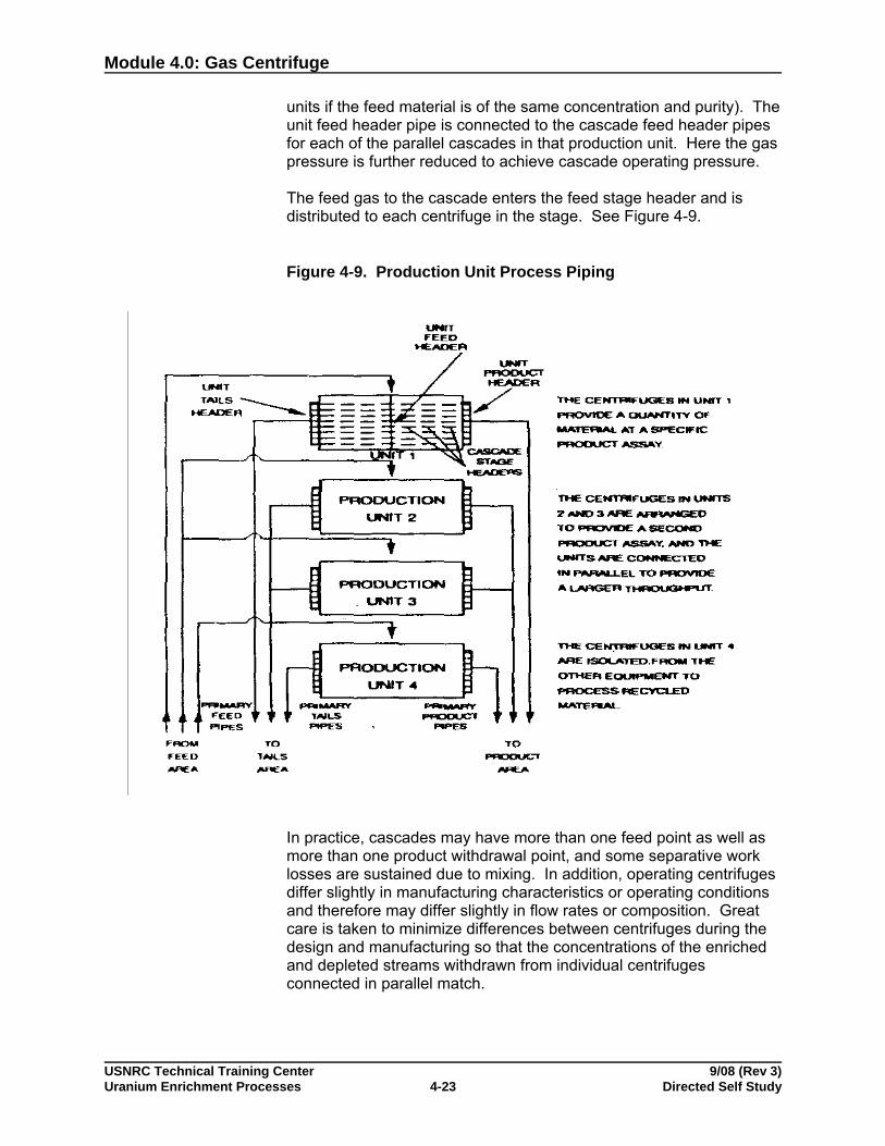
The feed gas to the cascade enters the feed stage header and isdistributed to each centrifuge in the stage. See Figure 4-9.
Figure 4-9. Production Unit Process Piping
In practice, cascades may have more than one feed point as well asmore than one product withdrawal point, and some separative worklosses are sustained due to mixing. In addition, operating centrifugesdiffer slightly in manufacturing characteristics or operating conditionsand therefore may differ slightly in flow rates or composition. Greatcare is taken to minimize differences between centrifuges during thedesign and manufacturing so that the concentrations of the enrichedand depleted streams withdrawn from individual centrifugesconnected in parallel match.
Module 4.0: Gas Centrifuge
USNRC Technical Training Center 9/08 (Rev 3)Uranium Enrichment Processes Directed Self Study4-24
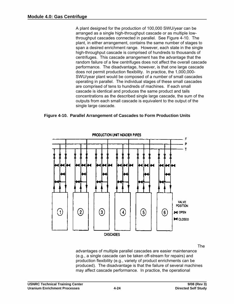
A plant designed for the production of 100,000 SWU/year can bearranged as a single high-throughput cascade or as multiple low-throughput cascades connected in parallel. See Figure 4-10. Theplant, in either arrangement, contains the same number of stages tospan a desired enrichment range. However, each state in the singlehigh-throughput cascade is comprised of hundreds to thousands ofcentrifuges. This cascade arrangement has the advantage that therandom failure of a few centrifuges does not affect the overall cascadeperformance. The disadvantage, however, is that one large cascadedoes not permit production flexibility. In practice, the 1,000,000-SWU/year plant would be composed of a number of small cascadesoperating in parallel. The individual stages of these small cascadesare comprised of tens to hundreds of machines. If each smallcascade is identical and produces the same product and tailsconcentrations as the described single large cascade, the sum of theoutputs from each small cascade is equivalent to the output of thesingle large cascade.
Figure 4-10. Parallel Arrangement of Cascades to Form Production Units
Theadvantages of multiple parallel cascades are easier maintenance(e.g., a single cascade can be taken off-stream for repairs) andproduction flexibility (e.g., variety of product enrichments can beproduced). The disadvantage is that the failure of several machinesmay affect cascade performance. In practice, the operational
Module 4.0: Gas Centrifuge
USNRC Technical Training Center 9/08 (Rev 3)Uranium Enrichment Processes Directed Self Study4-25
flexibility of a multiple cascade plant far outweighs the disadvantageof reduced cascade performance due to failed machines.
Product and TailsRemoval
After processing, the enriched gas from each centrifuge in the feedstage enters the stage product header; simultaneously, the depletedgas from each feed stage centrifuge enters the stage tails header.The stage product header becomes the feed header for the next stagein the cascade; the stage tails header becomes the feed header forthe previous stage. The gas is similarly processed through theenriching and stripping stages to achieve the desired concentrationrange. The product header of the top stage in the cascade is thecascade product header and empties into the unit product header; thetails header of the bottom stage is the cascade tails header andempties into the unit tails header.
The material in the unit headers is transferred directly to thewithdrawal areas through primary product and tails withdrawal pipes.(If the product and tails concentration for the production units areidentical, there may be only one primary product pipe and one primarytails pipe.)
In the withdrawal areas, cylinders are filled with the product and tailsmaterial. After the enriched and depleted streams leave thecascades, they are collected in desublimers where the gas solidifies. When full, the desublimers are heated and the UF6 is transferred,either as a gas or liquid (depending on the design), to empty cylinderswhere it solidifies. At some facilities, a compressor system may beused instead of desublimers to collect the product and/or tailsmaterial. Tails cylinders containing the depleted material are weighedand then moved to an onsite storage yard for long-term storage. Theproduct cylinders containing the enriched material are weighed, liquidsampled, possibly blended or rebatched, and then transferred to astorage area to await shipment offsite.
A secondary function of the product and tails removal systems is toprovide a rapid means of evacuation of UF6 from the centrifugecascades to avoid damages to the centrifuges produced fromabnormal operating conditions, such as high or low temperature, highpressure, or loss of drive to the centrifuges.
Dumping of a cascade to the product or tails removal system iseffected through bypassing of the cascade terminal control valve,which allows elevated flow rates of UF6 to the product or tailscylinders. In the event of loss of electrical power or instrumentcalibration, dumping of the cascades to the product or tails removalsystem is not possible. In this case, the contents of the cascadesmay be dumped to a contingency dump system. The contingencydump system is comprised of multiple trains of NaF absorber beds, surge vessels, and vacuum pumps. One train of contingency dumpequipment is provided for each cascade. When the cascade gas is

Module 4.0: Gas Centrifuge
USNRC Technical Training Center 9/08 (Rev 3)Uranium Enrichment Processes Directed Self Study4-26
vented through this system, UF6 is bound to the NaF absorber, and the remaining light gases are released to a gaseous effluent ventsystem.
Additional Piping-StructureComponents
Sampling ports are used to remove process samples from thecascade while it is operating. Evacuation and sampling ports areused to evacuate the process system before operation begins, toremove process samples from the cascade while it is operating, andto remove process gas prior to maintenance activities. The cascadefeed header port can also be used to fill the cascade with processgas. Depending on the design of the cascade, only one port may bepresent on each header, or there may be multiple ports throughout thecascade to permit the withdrawal of samples from individual stages.
An additional component is a cascade recycle line that joins thecascade product and tails headers to the feed header. With propersetting of the header pipe valves, the cascade can run indefinitely onthe same process gas by continuously recycling it. The recycle modeof operation is generally used to permit a cascade to reach the designproduct and tails concentrations (e.g., initial startup or restart followingmaintenance) before the cascade output is introduced to the processsystem and when the cascade is in standby mode. See Figure 4-11.
Figure 4-11. Cascade Header Piping
Module 4.0: Gas Centrifuge
USNRC Technical Training Center 9/08 (Rev 3)Uranium Enrichment Processes Directed Self Study4-27
Product Cylinders Empty product cylinders are weighed, inspected for contaminants,and evacuated. As needed, empty product cylinders are transportedto product take-off stations and connected to process piping. Anyprocess piping exposed to air is evacuated by a mobile vacuumpump.
During normal operations, enriched gaseous UF6 is continuouslywithdrawn from the centrifuge cascades. Vacuum pumps are used tomove the UF6 to product cylinders where the UF6 is solidified. Theproduct cylinders are located on a scale in an air-cooled cold chest. The fill weight is controlled to prevent cylinder rupture during productsampling when the cylinder is heated, causing the solid UF6 to expandduring transformation to the liquid state.
Each filled product cylinder is placed inside an autoclave, connectedby manifold to a product sample bottle, and heated. After the sampleis drawn, both the autoclave and sample bottle are cooled by chilledwater so that the UF6 is solidified before movement outside theautoclave.
Sampling Analyses Standard analyses performed on a sample include: (1) thedetermination of the uranium concentration by the gravimetric method,(2) the determination of the isotopic abundances and U-235 contentby gas-phase mass spectrometry, and (3) the determination ofimpurity content by a variety of techniques. Samples that may requireanalyses include UF6 samples from feed, product, and tails cylinders;process gas samples from the cascades; and other uranium-bearingsamples from scrap materials.
Product Blending A product blending system provides the means by which the contentsof two product cylinders can be mixed to give a final product of thedesired U-235 enrichment. For example, a system can consist of twoautoclaves containing larger donor product cylinders (e.g., 10 ton 48Xcylinders) selected for blending, plus five receiver stations that housereceiver cylinders (usually 2.5 ton 30B cylinders). Four of the fivecylinders are blending products, while the fifth receives the heels fromthe donor cylinders and the contents from the desublimer.
Blending is achieved by melting and vaporizing the UF6 in two donorautoclaves, then transferring the desired amount from each donorcylinder to air-cooled receiver cylinders. Flow control is used toachieve the desired mixture. Unblended heels are collected in aheels cylinder. This process would yield intermittent radioactivegaseous streams vented through a gaseous effluent vent system.

Module 4.0: Gas Centrifuge
USNRC Technical Training Center 9/08 (Rev 3)Uranium Enrichment Processes Directed Self Study4-28
Product Storageand ShippingSystem
The product storage and shipping system serves as a storage area forthe sampled and blended product cylinders. Product cylinders arestored resting on chocks. Cylinders are not stacked and adequateclearance should be provided for mobile carriers access. A cylinder isretrieved from storage with a mobile cylinder transporter andconveyed to a shipping area where it is weighed. With the use of anoverhead crane, the cylinder is then loaded onto a truck for shipping.
Tails Storage Tails cylinders, which contain solid UF6 and are under vacuum, arecarried via mobile transporter to a tails storage area. Cylinders aresupported by reinforced hardstand chocks. Cylinders are adequatelyspaced for loading and unloading needs. Commercial enrichmentcompanies currently plan to deconvert the DUF6 into U3O8 for longterm storage or disposal.
Waste Confinementand Management
Scrap recovery and waste treatment areas serve as the collection andprocessing point for all scrap and waste streams. Scrap and wastematerials from all areas in the plant are collected and stored untilrecovery or disposal occurs. Typical materials include contaminatedburnable and nonburnable wastes; alumina and/or sodium fluoridefrom chemical traps; decontamination solutions, other solutions, oils,and sludge from the decontamination and maintenance areas; andsamples and analytical wastes from an analytical laboratory.
Sewage In the case of liquid effluents, all releases are batched and can besampled before release, and all liquids leaving the centrifuge facilitycan be added to the normal continuous flow of sewage treatmentwater. That flow should be continuously sampled, composited, andanalyzed quarterly. Due to the batch nature of potential radioactivereleases to the sewage treatment water, an accidental release fromfailure of a single liquid waste line or tank is unlikely to reach thesewage effluents due to the series of holding tanks in the liquideffluent treatment system. For example, a facility can be designed sothat if a line or tank fails or overflows, the contents can flow to a floordrain that can divert the flow to another holding tank. However, if anaccident were to occur resulting in a serious liquid effluent release,additional samples could be taken as necessary for laboratoryanalysis of releases on a more frequent basis (e.g., daily or hourly) forgross alpha and beta radioactivity screening.
Sampling of sewage sludge for possible uranium accumulation shouldbe done on a semiannual basis.
Module 4.0: Gas Centrifuge
USNRC Technical Training Center 9/08 (Rev 3)Uranium Enrichment Processes Directed Self Study4-29
Self-Check Questions 4-2
Complete the following questions. Answers are located in the answer key section of theTrainee Guide.
1. What usually happens to UF6 feed cylinders upon receipt at the enrichment plant?
2. What is cold purification?
3. What is hot purification?

Module 4.0: Gas Centrifuge
USNRC Technical Training Center 9/08 (Rev 3)Uranium Enrichment Processes Directed Self Study4-30
4. What happens to the feed cylinder when it is almost empty?
5. What happens when the desublimer reaches its UF6 operational fill limit?
6. After feed purification, how is gaseous UF6 transferred from the feed cylinder to thecascade?
7. Why are centrifuges connected in series?
8. Why are centrifuges connected in parallel to form stages?
Module 4.0: Gas Centrifuge
USNRC Technical Training Center 9/08 (Rev 3)Uranium Enrichment Processes Directed Self Study4-31
9. What are the stages between the points where the feed is introduced and the product iswithdrawn called?
10. What are "stripping stages" or the "stripper"?
11. The number of stages that are connected in series to form a cascade depend on what?
12. What is the advantage of blending streams with identical isotopic concentration?
13. Why are the material flow rates different for each stage?
14. What is the material feed rate to a specific stage dependent on?
15. Which stage has the largest material flow rate and has the greatest number of centrifugesconnected in parallel?

Module 4.0: Gas Centrifuge
USNRC Technical Training Center 9/08 (Rev 3)Uranium Enrichment Processes Directed Self Study4-32
16. Are the centrifuges located at the product end of the cascade physically different fromthose at the tails end?
17. What are the advantages of using multiple small cascades connected in parallel?
18. What happens after the enriched and depleted streams leave the cascades?
19. What typically happens to filled tails cylinders?
20. What typically happens to filled product cylinders?
21. What is a secondary function of the product and tails removal systems?
Module 4.0: Gas Centrifuge
USNRC Technical Training Center 9/08 (Rev 3)Uranium Enrichment Processes Directed Self Study4-33
22. What is a contingency dump system comprised of and how does it work?
23. When are evacuation and sampling ports used?
24. When is the recycle mode of operation generally used?
25. Why is fill weight controlled on product cylinders?
26. What standard analyses are performed on samples?
Module 4.0: Gas Centrifuge
USNRC Technical Training Center 9/08 (Rev 3)Uranium Enrichment Processes Directed Self Study4-34
27. Where in the gas centrifuge process might samples be required for analyses?
28. How can product blending be achieved?
29. How are product cylinders stored?
30. What are some typical waste materials at a gas centrifuge facility?
31. How often should sampling of sewage sludge for possible uranium accumulation be done?
You have completed this section.Please check off your progress on the tracking form.
Go to the next section.
Module 4.0: Gas Centrifuge
USNRC Technical Training Center 9/08 (Rev 3)Uranium Enrichment Processes Directed Self Study4-35
Learning Objective
When you finish this section, you will be able to:
4.1.3 Identify the uses of the gas centrifuge process in industry and the requiredproduction amounts of enriched uranium.
INDUSTRIAL USE
United States The first gram quantities of enriched uranium were produced at theUniversity of Virginia in 1941. An improved device was operated byStandard Oil at the Bayway Refinery, New Jersey, in 1944. Westinghouse Electric manufactured the centrifuges in EastPittsburgh and built a small pilot plant in Bayonne, New Jersey. Engineering difficulties during World War II led to a decision toconcentrate efforts on the other processes. Gas centrifuge researchand development activities resumed in the early 1960s. In 1978 theU.S. Department of Energy committed itself to the construction of aGas Centrifuge Enrichment Plant (GCEP) on the site of thePortsmouth Gaseous Diffusion Plant in Piketon, Ohio. A pilot plantcomprised of 120 plant prototype centrifuges arranged in a singleprocess unit was constructed and successfully operated at OakRidge, Tennessee. A larger pilot plant of about 840 GCs wasoperated at Portsmouth for several months. This facility was shutdown in 1985 when, in the face of a diminished world nuclear powercommitment and the potential use of the AVLIS enrichment process,the DOE terminated all of its centrifuge activities including centrifugeresearch and development and GCEP construction.
Recent NRCLicensingExperience
Louisiana Energy Services (LES), a private consortium of Urenco,Fluor Daniels, Duke Power, Louisiana Power and Light and NorthernStates Power, filed a license application on January 31, 1991, to buildthe Claiborne Enrichment Center near Homer, Louisiana. The plantdesign was based on the Urenco Gas Centrifuge technology (seeUrenco below). Construction was expected to be complete in fiveyears and produce 1.5 MSWU per year. However, after seven yearsof delays in the licensing process (due to a number of issues thatarose) and investments of $34 million dollars, LES withdrew theapplication. Some of the issues included environmental justiceconcerns, enrichment needs, and DUF6 disposition. This is discussedfurther in Case Study 1, Claiborne Enrichment Center.
LES initiated discussions with the NRC on a new, larger GC facility of3 million SWU capacity in 2000–2002. Initially, the plant wasproposed for Hartsville, Tennessee (near Nashville). LESencountered difficulties with obtaining all of the local permits and

Module 4.0: Gas Centrifuge
USNRC Technical Training Center 9/08 (Rev 3)Uranium Enrichment Processes Directed Self Study4-36
subsequently moved the proposed site to New Mexico. LESsubmitted a license application in December 2003. The plant isnamed the National Enrichment Facility (NEF). The license wasissued in 2006 and construction has begun on the actual facility. Thisis discussed further in Case Study 2.
USEC has had continuing discussions with the NRC about installingnew enrichment technologies since 1998. USEC applied for a licensefor a Lead Cascade Facility in February 2003, which was planned asa pilot plant for testing cascade operations of up to 240 of the DOEGC design. Materials would be recycled, without any productstreams. Only samples would be taken of the enriched product. TheNRC issued the license in February 2004 – a fast turnaround waspossible because it would be a small facility without an enrichedproduct, and no EIS was required. Construction of this facility hasbeen completed and operation is anticipated in late 2007 or early2008. USEC submitted a license for the large scale plant, termed theAmerican Centrifuge Facility (ACP), in August 2006. ACP is plannedas a 3.8 million SWU/yr facility. The license was issued in 2007 andconstruction has commenced on the actual facility. This is discussedfurther in Case Study 3.
Areva has initiated discussions with the NRC about licensing a newGC enrichment facility in the U.S. Few specifics are currentlyavailable but it appears to be a 1 MSWU/yr or larger plant utilizingUrenco GC technology.
United Kingdom, theNetherlands, andGermany
In Europe, gas centrifuge has been developed to a commercial levelby Urenco–Centec, an industrial group formed by British, German,and Dutch companies. The group operates enrichment plants in theUnited Kingdom, the Netherlands, and Germany. By 1972, pilotplants at Capenhurst (United Kingdom) and Almelo (the Netherlands)were well under construction and, in fact, partially operational, havingbeen already started under the national programs even before theformation of Urenco. These pilot plants have been shut down exceptfor the SP2 pilot plant at Almelo.
Urenco followed the pilot plants with two demonstration plants (200tonne SWU/year [200,000 SWU/yr] each) to further establish thecommercial viability of its process, and these were in turn followed bycommercial plants of larger size. The Capenhurst E21 DemonstrationFacility was shut down in 1991. The centrifuge cascades at theAlmelo plant are individually-mounted machines (i.e., machines with asingle rotor in each vacuum casing). Each machine requires threesmall process lines: one each for the feed, product, and “waste” DU. These lines connect to the three main piping headers (for feed,product, and tails) running the length of the cascade.
The centrifuge cascades at Gronau, Germany, are an example ofblock-mounted design (i.e., centrifuges comprised of a number of

Module 4.0: Gas Centrifuge
USNRC Technical Training Center 9/08 (Rev 3)Uranium Enrichment Processes Directed Self Study4-37
rotors mounted in a common vacuum housing). Gronau also has alarge number of the newer, higher capacity, individually mountedcentrifuges. The British version of a block-mounted design has alsobeen installed at Capenhurst. Urenco has introduced a newgeneration of machines every five to seven years. Some firstgeneration machines have operated 30 years with a failure rate ofless than one percent. Urenco has installed fifth generation machinesand has brought sixth generation machines into production in the1998–2001 time frame. The fifth and sixth generation machines aretermed TC-12 and TC-21, with capacities of cirica 40 and 90 SWU/peryr GC, respectively. Centrifuge improvements include increasing thelength, as well as introducing new materials, and increasing the rotorspeed.
Other centrifuge plant improvements have been to move towardsindividually-mounted machines and providing higher outputs. Newplants withdraw process gas directly into product and tails cylinderseliminating the need for sublimers. In the future, more concentrationwill be placed on manufacturing and plant performance rather thandeveloping another generation of centrifuge.
The current capacity of the combined Urenco enrichment facilities is7.5 million SWU per year. In 1998, Urenco was in the process ofinstalling seven new cascades at the Capenhurst site in the UnitedKingdom. There are also plans to expand the Almelo plant in theNetherlands. In late 1998, Urenco applied for a license to increasethe capacity of the Gronau plant in Germany from one million to fourmillion SWU per year. Figure 4-12 shows an Urenco cascade. Figure4-13 shows block mounted designs.

Module 4.0: Gas Centrifuge
USNRC Technical Training Center 9/08 (Rev 3)Uranium Enrichment Processes Directed Self Study4-38
Figure 4-12. View of an Urenco Cascade
Figure 4-13. Block Mounted Designs
Module 4.0: Gas Centrifuge
USNRC Technical Training Center 9/08 (Rev 3)Uranium Enrichment Processes Directed Self Study4-39
Japan In Japan, the Power Reactor and Nuclear Fuel DevelopmentCorporation (PNC) and the Japan Nuclear Fuel Limited (JNFL)operate small centrifuge plants. The PNC of Japan operates gascentrifuge facilities at Ningyo Toge. The pilot plant was completed in1982 with a nominal separative capacity of 75,000 SWU per year. This facility was shut down in 1990 and dismantled. The Ningyo TogeWorks demonstration plant consists of two operation units, DOP-1and DOP-2. Each unit has a separation capacity of 100,000 SWU peryear. DOP-1 began operating in April 1988, and DOP-2 started up inMay 1989.
Technology developed at the Ningyo Toge Works facility was appliedto Japan's commercial enrichment plant at Rokkasho-mura. TheRokkasho Uranium Enrichment Plant is operated by Japan NuclearFuel Limited (NJFL) and its initial unit output of 150,000 SWU per yearbecame fully operational in March 1992. Phase I of the plant wascompleted in September 1994 adding another 450,000 SWU per yearfor a total annual capacity of 600,000 SWU. Phase II, whichcommenced construction in September 1993, will add increments of150,000 SWU per year until it reaches an annual capacity of 900,000SWU. One half of this planned capacity (450,000 SWU per year) wasoperational by October 1998. This will bring Rokkasho capacity to1,050,000 SWU.
The Rokkasho-based Nuclear Fuel Machinery Corporation,established in May 1998 by Japan Nuclear Fuel Limited, was mergedwith Uranium Enrichment Machinery Limited in November 1998. Theshareholders of the merged company will be JNFL, Toshiba, Hitachi,and Mitsubishi Heavy Industries. The company will work to integrateJapan's enrichment technologies and develop and manufactureadvanced centrifuges. It will be responsible for the development,design, and manufacture of enrichment plant equipment, while JNFLwill retain responsibility for plant operation. Currently, Rokkasho isrunning at about 1.5 MSWU/yr.
Russia Russia's gas centrifuge project began in October 1957 by the startupof its first pilot plant. The world's first gas centrifuge production plantlocated near Ekaterinburg commenced operation in 1959. Russiacurrently has four operating gas centrifuge plants located inNovouralsk (also referred to as Ekaterinburg and Verkh Nervinskiy),Krasnoyarsk, Tomsk, and Angarsk. Russia's 18 to 20 million SWUper year enrichment capacity is entirely centrifuge based. Russiainitially employed gaseous diffusion technology but it was phased outin the early 1960's. It is still sometimes used as a first stage toeliminate chemical impurities. The Urals Electro-Chemical Plant nearEkaterinburg has the largest capacity (approximately 10 million SWUper year) and can achieve the highest enrichments. In theirtechnology, the cascades consist of a compact arrangement ofvertically stacked gas centrifuges. (Figure 4-14) The stack mayconsist of three to five individual centrifuges.

Module 4.0: Gas Centrifuge
USNRC Technical Training Center 9/08 (Rev 3)Uranium Enrichment Processes Directed Self Study4-40
Floor viewGCs also stackedvertically
Top View[from Internet and DOE/ORNL papers]
Floor viewGCs also stackedvertically
Floor viewGCs also stackedvertically
Top View[from Internet and DOE/ORNL papers]
Top View[from Internet and DOE/ORNL papers]
Figure 4-14. Russian GCs

Module 4.0: Gas Centrifuge
USNRC Technical Training Center 9/08 (Rev 3)Uranium Enrichment Processes Directed Self Study4-41
China In April 1996, Russia announced that they had signed a contract todeliver centrifuges for a 200,000 SWU per year plant in China. Chinahad planned to have this capacity installed by the end of 1996,although enrichment requirements would not arise until after the year2000. This ambitious schedule for installing the 200,000 SWU hasnot been reached. Knowledgeable persons in the enrichment fieldbelieve that about 50,000 SWU per year may have been installed byearly 1999. In January 1999, Russia and China signed a furthernuclear cooperation protocol that provided for Russian involvement inthe construction of a gas centrifuge enrichment plant in China andjoint development of new generation centrifuges. In early 1999, it wasannounced that the third and fourth sections of the enrichment plant(50,000 SWU per year per section) using current generation machinesare scheduled for completion in 2001.
France France (Areva), via the Eurodif consortium, operates the GaseousDiffusion Plant at Tricastin, discussed in Module 2. Eurodif hasdecided to convert the facility to a GC plant because of increases inthe prices of energy and electricity. A contractual relationship hasbeen formed with Urenco, including the formation of a company calledETC for GC manufacture. Urenco, via ETC, will supply new GCs andreceive old or damaged GCs back; Eurodif and Areva will not haveaccess to GC technology. The Eurodif plan has three phases spreadout over the next 5–10 years. Each phase introduces 2-3 MSWU/yr ofGC capacity and retires an equivalent amount of GDP capacity. When completed, the new GC facility will have a SWU capacityequivalent to the existing GDP (about 7.5–8 MSWU/yr) but use 100MWe or less, as compared to about 2,500 MWe for the existing GDP. Current plans utilize the Urenco TC-12 design. The phased approachallows the use of the higher capacity, TC-21 design as an option ifEurodif decides it is needed to meet customer demand.
Module 4.0: Gas Centrifuge
USNRC Technical Training Center 9/08 (Rev 3)Uranium Enrichment Processes Directed Self Study4-42
Activity 1 - Gas Centrifuge WorldWide Web Sites*
Purpose: The purpose of this activity is to view international gascentrifuge information posted on the World Wide Web.
Instructions: Access the Internet. Search the World Wide Web by keying in one of thefollowing addresses:
http://www.urenco.com (Urenco - check out the locations and associated facility pictures)
http://www.jnfl.co.jp (Japan Nuclear Fuel Limited)
* This is an optional activity and is not required for module completion.

Module 4.0: Gas Centrifuge
USNRC Technical Training Center 9/08 (Rev 3)Uranium Enrichment Processes Directed Self Study4-43
Self-Check Questions 4-3
Complete the following questions. Answers are located in the answer key section of theTrainee Guide.
1. Is there a gas centrifuge enrichment facility operating in the United States?
2. What countries presently have gas centrifuges in operation?
3. How are the centrifuge cascades at the Almelo plant in the Netherlands mounted?
4. What type of centrifuge cascade design is used at Gronau, Germany?
5. What are some centrifuge plant improvements achieved by Urenco?

Module 4.0: Gas Centrifuge
USNRC Technical Training Center 9/08 (Rev 3)Uranium Enrichment Processes Directed Self Study4-44
6. What is unique about the cascade technology that Russia has imported to China?
You have completed this section.Please check off your progress on the tracking form.
Go to the next section.

Module 4.0: Gas Centrifuge
USNRC Technical Training Center 9/08 (Rev 3)Uranium Enrichment Processes Directed Self Study4-45
Learning Objective
When you finish this section, you will be able to:
4.1.4 Identify the hazards and safety concerns for the gas centrifuge process, includingmajor incidents.
HAZARDS ANDSAFETYCONCERNS
The primary hazard at a gas centrifuge facility is uraniumhexafluoride. A secondary potential hazard is stored quantities ofchlorinated compounds, primarily refrigerants, used in traps anddesublimer coils. Expected UF6 release events include leaks fromprocess connections and equipment with a minimal impact on and offthe gas centrifuge site. Releases from process piping following anearthquake could produce uranium intakes offsite. The largest impactcould occur following a catastrophic failure of a hot cylinder containingliquefied UF6. Liquefied UF6 is normally present in the autoclaveswhere process control systems and redundant protection circuits limitthe likelihood of cylinder overheating.
Gas centrifuge enrichment plants pose hazards associated withhandling UF6 and enriched uranium, as well as hazards that are alsofound in other industries–particularly those posed by the use of high-speed rotating equipment. A gas centrifuge unit operating at highspeeds could generate flying pieces of equipment and material(shrapnel) as a result of the destruction of the rotor and other spinningcomponents.
The plants are designed to be run continuously for periods in excessof ten years, and reliability and ease of maintenance are of paramountimportance, for both safety and economic reasons. Operationalexperience with centrifuge plants has been good. Plants havegenerally been very reliable and performed well with low levels of UF6release during normal operations. In addition, there have been only afew minor mechanical failures.
Potential significant accidents at one GC facility are summarized onTable 4-2.
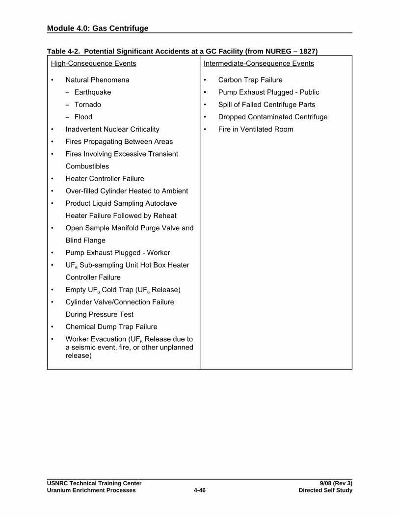
Module 4.0: Gas Centrifuge
USNRC Technical Training Center 9/08 (Rev 3)Uranium Enrichment Processes Directed Self Study4-46
Table 4-2. Potential Significant Accidents at a GC Facility (from NUREG – 1827)High-Consequence Events
• Natural Phenomena
S Earthquake
S Tornado
S Flood
• Inadvertent Nuclear Criticality
• Fires Propagating Between Areas
• Fires Involving Excessive Transient
Combustibles
• Heater Controller Failure
• Over-filled Cylinder Heated to Ambient
• Product Liquid Sampling Autoclave
Heater Failure Followed by Reheat
• Open Sample Manifold Purge Valve and
Blind Flange
• Pump Exhaust Plugged - Worker
• UF6 Sub-sampling Unit Hot Box Heater
Controller Failure
• Empty UF6 Cold Trap (UF6 Release)
• Cylinder Valve/Connection Failure
During Pressure Test
• Chemical Dump Trap Failure
• Worker Evacuation (UF6 Release due toa seismic event, fire, or other unplannedrelease)
Intermediate-Consequence Events
• Carbon Trap Failure
• Pump Exhaust Plugged - Public
• Spill of Failed Centrifuge Parts
• Dropped Contaminated Centrifuge
• Fire in Ventilated Room

Module 4.0: Gas Centrifuge
USNRC Technical Training Center 9/08 (Rev 3)Uranium Enrichment Processes Directed Self Study4-47
Chemical andChemical ReactionHazards
Nitrogen is used for purging, blanketing, and drying vessels and linesto make sure that uranium does not react with trapped moisture in thesystem and deposit on surfaces.
Sodium hydroxide (NaOH) is used to adjust the pH of wastewaterfrom decontamination facilities. It is in powder form and then mixedwith water. Releases from NaOH spills would damage vegetation.
Citric acid (C6H8O7) is used to decontaminate equipment. It istransported in granular form. Spills of C6H8O7 may lead to pHreduction of water solutions and if sufficient amounts are released itcould damage vegetation in the immediate area of a spill.
Chlorofluorocarbons (CFCs) are used to cool water and air and toimprove the enrichment process efficiency. They are also used assolvents for degreasing equipment.
The gaseous chemical effluent of major concern is hydrofluoric acid(HF) produced by the hydrolysis of UF6.
The following are contributing factors to chemical and chemicalreaction hazards:
• UF6 reacts explosively with organic material to form fluorinatedcompounds and HF
• HF and F2 releases from fluorine generation and feed processes
• UF6 reacts with H2O or wet air to form highly corrosive and toxicHF
• H2 formation within process stream
• Contaminants introduced with recycled UF6 feed (e.g.,transuranics and Tc)
• Potential UF6 reaction with H2O in autoclave, resulting in formationof HF and UO2F2 and a resultant increase in pressure
• Exothermic reactions resulting in uranium compound deposits(e.g., UF4)
• Hydrostatic burst of an over-filled UF6 cylinder when the liquid UF6 solidifies and its volume increases sharply
Physical/MechanicalHazards
The following are contributing factors to physical/mechanical hazards:
• High-speed rotating equipment

Module 4.0: Gas Centrifuge
USNRC Technical Training Center 9/08 (Rev 3)Uranium Enrichment Processes Directed Self Study4-48
• A gas centrifuge unit operating at high speeds could generateflying pieces of equipment and material as a result of thedestruction of the rotor and other spinning components
• Failure of centrifuge could cause centrifuge to fall over
• Normal heavy industrial chemical processing plant hazards inassembly, disassembly, and cleaning areas (solvents, acids)
• Hoisting and rigging and crane movement hazards
• Normal electrical shock hazards from faulty equipment ormaintenance at switch yards and transformers
• Rupture of product cylinder by overfilling
RadiologicalHazards
The predominant radioactive material utilized at a gas centrifuge siteis natural, low-enriched, and depleted uranium primarily in the form ofuranium hexafluoride. A primary concern for gas centrifugeoperations is incidental or accidental inhalation of uranium, which cancause non-stochastic chemical damage to the kidney (nephrotoxicity)if intakes exceed a threshold within a specified period of time. Significant releases of UF6 to work areas are unlikely, since the entirecentrifuge system, with the exception of the autoclaves, is operated ina partial vacuum so that leaks are into the system, not into the workareas.
Most of the radioisotopes that could be encountered emit alpha andbeta particles, which are non-penetrating forms of radiation that wouldbe shielded from workers by UF6 storage cylinders and primarycontainment systems (i.e., process lines). Due to high density of UF6when stored as a solid, the material would also provide considerableself-attenuation of x-rays and gamma rays from the uranium seriesnuclides present. A significant portion of the direct radiationencountered would be in the form of Bremsstrahlung radiation, whichwould be generated by the interaction of beta radiation with highatomic number atoms, such as uranium in UF6 and, to a lesser extent,iron in UF6 cylinders.
The following are contributing factors to radiological hazards:
• Low-level alpha radiation from U oxide
• High gamma radiation from cylinders (with heels) and tailscylinders
• UF6 release from failure of safety systems on autoclaves, coldtraps, and vacuum pumps

Module 4.0: Gas Centrifuge
USNRC Technical Training Center 9/08 (Rev 3)Uranium Enrichment Processes Directed Self Study4-49
Most of the other sources of radioactivity utilized at a gas centrifuge facility are calibration and radiochemistry (quality control) standardswhich pose little radiation exposure risk to workers and none to thepublic.
Note: Neutron dose primarily for cylinder handlers can also occur ata gas centrifuge facility. Please refer to the discussion ofneutron dose addressed in Module 2.0, “Gaseous Diffusion.”
Radiological doses at existing GC facilities are low. Urenco radiationworkers receive on average, about 40 mrem/yr with the highestindividual dose around 260 mrem/yr.
Nuclear CriticalitySafety
Nuclear criticality safety depends on several key parameters,including assay level, quantity, concentration (for solutions),moderators (presence and type), reflectors (presence, type, andthickness), chemical forms, geometry, and physical properties, suchas density. Figures 4-15, 4-16, and 4-17 show some of these effects. Most notably, the required critical mass quantities increaseconsiderably as the assay decreases, and are asymptotic (about 1%for homogeneous and about 0.7% for heterogeneous reflection). InFigure 4-15, note that the heterogeneous water full reflected criticalmass at 10% assay is about 11 kg, about 30 kg at 5% assay, andabout 150 kg at 2% assay. Figure 4-16 represents UO2 systems andindicates similar critical mass values. Figure 4-17 shows themultiplying factors for criticality masses and geometries as comparedto 100% assay. Although not explicitly shown on the Figures 4-15, 4-16 and 4-17 a moderator is not required for criticality at assaysabove approximately 7%. Criticality safety reviews use experimentaldata, and validated and benchmarked computer codes as part of theirassessment.

Module 4.0: Gas Centrifuge
USNRC Technical Training Center 9/08 (Rev 3)Uranium Enrichment Processes Directed Self Study4-50
Figure 4-15. The Effect of the Assay Level Upon the Minimum Critical Mass (from LA-0860-MS, “Criticality Dimensions of Systems Containing U-235, Pu-239, andU-233")

Module 4.0: Gas Centrifuge
USNRC Technical Training Center 9/08 (Rev 3)Uranium Enrichment Processes Directed Self Study4-51
Figure 4-16. UO2 and Water Systems (from TID-7016, “Nuclear Safety Guide,” Rev. 2)

Module 4.0: Gas Centrifuge
USNRC Technical Training Center 9/08 (Rev 3)Uranium Enrichment Processes Directed Self Study4-52
Figure 4-17. The Impact of Assay Upon Critical Masses, Volumes, and Geometries (from TID-7016)
Module 4.0: Gas Centrifuge
USNRC Technical Training Center 9/08 (Rev 3)Uranium Enrichment Processes Directed Self Study4-53
Abnormal operations that could affect nuclear criticality safety at GCfacilities include the presence of moderating material in an emptyproduct cylinder, the presence of moderating material in or added to afilled cylinder, and the production of enrichments above 5 wt % U-235.
Product cylinders containing UF6 enriched to 5.020 wt % U-235 arecritically safe if moderators are limited and controlled. If a filledcylinder at ambient temperature were punctured, enough water couldenter the cylinder and moderate enough enriched uranium to form acritical mass. Avoiding this occurrence requires that special handlingequipment be used by trained operators.
The following are contributing factors to nuclear criticality safetyhazards:
• Uncontrolled acceleration of rotor could cause increasedassay within multiple centrifuges
• Possible vacuum pump oil in unsafe geometry for assaypresent if pump demister fails
• Critical reaction possible in decontamination/cleaning area ifsolutions are stored/mixed incorrectly or allowed to assumeunsafe geometry
• Breach of UF6 containment (centrifuge, piping, cylinders,valves, etc.) could cause critical reaction if moderation ispresent
• Safe spacing violation
The uranium in all centrifuges is normally in the form of gaseous UF6at substantially below atmospheric pressure. As a result, only smallquantities (a few grams) of uranium exist in the centrifuges at any onetime. Loss of containment of the UF6 gas does not provide asignificant criticality hazard or risk because the density of the gasbelow atmospheric pressure is very low and only a few grams ofuranium are in any centrifuge. Thus, the release of UF6 would have tooccur from many centrifuges before a critical mass of uranium wouldbe released. If containment were lost while the containment wasbelow atmospheric pressure, in-leakage of moist air would occur. Themoisture would react with the UF6, and the resulting UO2F2 wouldsettle out in small quantities in each centrifuge. The increasedpressure in the cascades would cause control room alarms and thesolid UO2F2 would likely cause GC failure but it is unlikely to have anycriticality safety significance.
Significant quantities of enriched uranium are handled in the productareas. The use of moderators such as water and hydrocarbon oils inthe UF6 process areas must be controlled. A general approach tonuclear criticality safety is to prevent enrichment excesses, use

Module 4.0: Gas Centrifuge
USNRC Technical Training Center 9/08 (Rev 3)Uranium Enrichment Processes Directed Self Study4-54
favorable geometry equipment when practicable, provide moderationcontrol within the UF6 enrichment process, and sampling transfer, andwithdrawal operations and use strict mass and geometry controls onsolutions. In general moderation control is more crucial in sampling,transfer, and withdrawal than in actual enrichment, and geometrycontrol is usually used with solutions.
Fire and ExplosiveHazards
The chance of fires in a centrifuge plant should be less than in agaseous diffusion plant. The presence of large motors andcompressors in a diffusion plant creates elevated temperatures thatcould cause materials of construction to be at a higher temperaturethan those in a centrifuge plant. Also, the presence of lubricating oilaround motors and compressors presents a fire hazard.
The following are contributing factors to fire and explosive hazards:
• Presence of flammable cleaning solutions
• HF and F2 presence in the feed process
• Potential explosive reactions during mechanical failures
Gas centrifuge facilities may include fire protection features such asthe use of noncombustible or limited combustible materials forconstruction and fire barriers rated for fire resistance to meetcompliance with National Fire Protection Association (NFPA)requirements. Buildings may be protected by wet-pipe sprinklersystems, except certain areas such as a central control room that contain electrical switch gear and batteries. These areas requireprotection by automatic pre-action sprinkler systems. Waterdeflectors or enclosures should also be provided in areas presentinga potential hazard of criticality.
A fire water system with redundant equipment in addition to portablefire extinguishers enhances fire protection. A facility-wide fire alarm, atrained and equipped fire brigade, and a fire protection equipmentmaintenance program are also needed for adequate fire protection.
Environmental andNatural Disasters
Enrichment plants are designed to protect equipment, the workforceand the public in the cases of weather and seismic events. Designsmust accommodate such site area specific factors as expected windand snow loads on the building, flooding history, and groundmovement parameters in the event of an earthquake. Generally, thedesign accommodates 1000-year or longer occurrence conditions thatare judged to be sufficiently rare that all interests are protected.
Past Events The types of off-normal events that have occurred in operating theEuropean gas centrifuge plants are summarized in Table 4-3. The

Module 4.0: Gas Centrifuge
USNRC Technical Training Center 9/08 (Rev 3)Uranium Enrichment Processes Directed Self Study4-55
data indicates that leaks from disconnecting piping and from pumpseal failures are the most frequent events that lead to UF6 releases. For these two types of events, estimated release quantities are on theorder of tens of grams and frequencies are on the order of twice perplant operating year. Line disconnection losses have occurred withmobile pump set equipment, with pump maintenance, and withsampling manifold handling. Operator error related to degassing linesand handling sampling manifolds played a role in this type of event. Pump failures involved failure of seals on rotating equipment, in someinstances, related to blockage of the pump exhaust line. Off-normalevents in the autoclaves have been limited to small leaks in theflexible piping and in valves in the cylinder exhaust line. Response tothe in-plant leaks have included revision of operating procedures andtraining of workers. Off-normal events related to cylinders werelimited to damage to cylinder valves due to collision with handlingequipment and leaks from cylinder valve packing nuts. Leaks of thistype were temporarily sealed with tape prior to replacement of thedamaged valve. Response to the events included reconfiguration ofthe cylinder storage area and redesign of the packing nuts. Eventsthat have occurred at the Urenco plants have not produced significantreleases of UF6 to the environment.

Module 4.0: Gas Centrifuge
USNRC Technical Training Center 9/08 (Rev 3)Uranium Enrichment Processes Directed Self Study4-56
Table 4-3. Urenco Operating Experience with UF6 Leaks
Type of Incident Number ofIncidents Cause Response
Line connect/disconnectleak 5 Inadequate degassing of
lines
Revise operating andmaintenanceprocedures
Pump seal failure5 Mechanical failure of
seals
Review pressuremonitoring,instrument calibration
Sampling manifold leak5 Rupture of temporary
containment
Revise training andoperating procedure,train staff
Flexible line leak 1 Steam condensation/galvanic corrosion Remove lagging
Feed system valve leak 1 Formation of deposits Reposition andinspect valves
Cylinder packing nutcracking several Stress corrosion cracking Redesign and
replace packing nuts
Cylinder valve leak 2 Mechanical impact Revise procedures
Inadvertent UF6 venting 1 Operating error
Module 4.0: Gas Centrifuge
USNRC Technical Training Center 9/08 (Rev 3)Uranium Enrichment Processes Directed Self Study4-57
SAFETYSIGNIFICANTSCENARIOS
CentrifugeContainment Failure
In a centrifuge failure, rotational energy is converted to heat, the rotordisintegrates, and a quantity of gas is generated in the disintegrationprocess and subsequent reaction with UF6. A pressure pulseoccurring during the crash closes isolation valves and separates thefailed centrifuge from the balance of the cascade. Solid reactionproducts accumulate in the bottom of the failed centrifuge, and over aperiod of weeks, the reaction gases leak into the cascade header andare removed through the gaseous effluent vent system. The failedcentrifuge remains in place but no longer contributes to the separationcapacity of the cascade.
UF6 CylinderFailures
UF6 cylinder failures may include:
• Introduction of reactive hydrocarbons into a cylinder
• Impact of a liquid-filled cylinder against or from an object
• Valve or pigtail failure due to movement of a connectedcylinder containing UF6
• Hydraulic rupture of a cylinder exposed to fire
• Hydraulic rupture of an overheated cylinder
• Hydraulic rupture of an overfilled cylinder
• Heating or filling a defective cylinder
• Heating a cylinder containing excessive volatile and/orgaseous contaminants
• Dropping a liquid-filled cylinder
UF6 Process SystemFailures
UF6 process system failures may include:
• Excessive heating of process equipment containing solidifiedUF6
• Fatigue failure of a process system
• Impact of an object on a process system containing UF6
• Valve failure of a cylinder or a system containing UF6
• Pigtail failure

Module 4.0: Gas Centrifuge
USNRC Technical Training Center 9/08 (Rev 3)Uranium Enrichment Processes Directed Self Study4-58
• Process system loss of containment caused by naturalphenomena
• Heating a cold trap containing excessive volatile and/orgaseous contaminants
• Heating an overfilled cold trap
• Overheating a cold trap
• Cold trap failure caused by corrosion, fatigue, or thermal shock
• Venting of UF6 through a hydrolyzer
Failure to De-GasProcess Lines
Connection and disconnection of lines potentially containing UF6occurs as a normal element of gas centrifuge operations. Operatingprocedures should specify that the lines are evacuated or de-gassedprior to disconnection. Past experience has demonstrated thatprocedures are occasionally misunderstood or improperly executedresulting in an uncontrolled release of UF6 into the process area. Events of this type are represented by consideration of disconnectionof a vacuum pump for maintenance. Surveys conducted after eventsof this type at Urenco facilities have reported negligible worker doses.
Flexible Pipe Leakin DesublimerTransfer
Feed purification desublimers containing solid UF6 are emptied byindirect heating with Freon and transfer of the sublimed material to acylinder in the purification cubicle. The take-up cylinder is connectedto the transfer piping using flexible pipe for which leaks have beenexperienced.
Module 4.0: Gas Centrifuge
USNRC Technical Training Center 9/08 (Rev 3)Uranium Enrichment Processes Directed Self Study4-59
Self-Check Questions 4-4
Complete the following questions. Answers are located in the answer key section of theTrainee Guide.
Fill in the missing words in each statement. Answers are located in the answer key section ofthe Trainee Guide. Choose from the following words:
autoclavesBremsstrahlungcleaningcompoundscontrolledcriticalcriticalitydecontaminatedensity
emptyenrichmentF25 wt%hydrofluoric acidinhalationkidneyliquefiedmanifold
materialmechanicalmobilemoderatorsnitrogennuclearpHpipingprocedures
publicradioisotopesrotorsealsolvents uranium hexafluoride
1. The primary hazard at a gas centrifuge facility is .
2. A secondary potential hazard is stored quantities of chlorinated ,primarily refrigerants.
3. The largest impact could occur following a catastrophic failure of a hot cylinder containing UF6.
4. A gas centrifuge unit operating at high speeds could generate flying pieces of equipmentand material as a result of the destruction of the and otherspinning components.
5. is used for purging, blanketing, and drying vessels and lines tomake sure that uranium does not react with trapped moisture in the system and deposit onsurfaces.
6. Sodium hydroxide (NaOH) is used to adjust the of wastewaterfrom decontamination facilities.
7. Citric acid (C6H8O7) is used to equipment.
8. Chlorofluorocarbons (CFCs) are used to cool water and air and to improve the process efficiency. They are also used as for degreasing equipment.
9. The gaseous chemical effluent of major concern is produced bythe hydrolysis of UF6.
Module 4.0: Gas Centrifuge
USNRC Technical Training Center 9/08 (Rev 3)Uranium Enrichment Processes Directed Self Study4-60
10. The predominant radioactive utilized at a gas centrifuge sitewill be natural, low-enriched, and depleted uranium primarily in the form of uraniumhexafluoride.
11. A primary concern for gas centrifuge operations is incidental or accidental of uranium, which can cause non-stochastic chemical damageto the (nephrotoxicity) if intakes exceed a threshold within aspecified period of time.
12. Significant releases of UF6 to work areas are unlikely, since the entire centrifuge system,with the exception of the , is operated in a partial vacuum so thatleaks are into the system, not into the work areas.
13. Most of the that could be encountered emit alpha and betaparticles, which are non-penetrating forms of radiation that would be shielded from workersby UF6 storage cylinders and primary containment systems (i.e., process lines).
14. Due to the high of UF6 when stored as a solid, the materialwould also provide considerable self-attenuation of x-rays and gamma rays from theuranium series nuclides present.
15. A significant portion of the direct radiation encountered would be in the form of radiation, which would be generated by the interaction of betaradiation with high atomic number atoms, such as uranium in UF6 and, to a lesser extent,iron in UF6 cylinders.
16. Abnormal operations that could affect nuclear criticality safety include the presence ofmoderating material in an product cylinder, and the production ofenrichments above U-235.
17. Product cylinders containing UF6 enriched to 5.020 wt % U-235 are critically safe ifmoderators are limited and .
18. If a filled cylinder at ambient temperature were punctured, enough water could enter thecylinder and moderate enough enriched uranium to form a mass.
19. Loss of containment of the UF6 gas does not provide a significant hazard or risk because the density of the gas below atmospheric pressure is very low andonly a few grams of uranium are in any centrifuge.
20. The use of such as water and hydrocarbon oils in the UF6process areas must be controlled.
21. A general approach to criticality safety is to prevent enrichmentexcesses, use favorable geometry equipment when practicable, provide moderation controlwithin the UF6 enrichment process, and use strict mass control on solutions.

Module 4.0: Gas Centrifuge
USNRC Technical Training Center 9/08 (Rev 3)Uranium Enrichment Processes Directed Self Study4-61
22. Fire and explosive hazards may include the presence of flammable solutions, HF and ___ presence in the feed process, and potential explosivereactions during failures.
23. Enrichment plants are designed to protect equipment, the workforce and the in the cases of weather and seismic events.
24. Past incidents indicate that leaks from disconnecting andfrom pump failures are the most frequent events that lead toUF6 releases.
25. Line disconnection losses have occurred with pump setequipment, with pump maintenance, and with sampling handling.
26. Response to the in-plant leaks have included revision of operating and training of workers.
Complete the following questions. Answers are located in the answer key section of theTrainee Guide.
27. What happens during a centrifuge containment failure?
28. List three contributing factors that may cause a UF6 cylinder failure.

Module 4.0: Gas Centrifuge
USNRC Technical Training Center 9/08 (Rev 3)Uranium Enrichment Processes Directed Self Study4-62
29. List three contributing factors that may cause a UF6 process system failure.
30. Have leaks occurred when a take-up cylinder is connected to the transfer piping usingflexible pipe?
Module 4.0: Gas Centrifuge
USNRC Technical Training Center 9/08 (Rev 3)Uranium Enrichment Processes Directed Self Study4-63
Learning Objective
When you finish this section, you will be able to:
4.1.5 Summarize Case Study 1: Summary of Proposed Claiborne Enrichment Center.
CASE STUDY 1:CLAIBORNEENRICHMENTCENTER
Overview On January 31, 1991, Louisiana Energy Services (LES) submitted alicense application to construct and operate a uranium enrichmentfacility near Homer, Louisiana, in Claiborne Parish. The facility, to becalled Claiborne Enrichment Center (CEC), would enrich uranium to amaximum 5 percent uranium-235 by the gas centrifuge process, andwould have a capacity of about 1.5 million separative work units(SWUs) per year. If licensed, LES would receive a combined 30-yearlicense for construction and operation. This facility would become thefirst privately owned enrichment facility in the United States.
The staff completed its review of the license application. The SafetyEvaluation Report was issued in January 1994 as NUREG-1491; theFinal Environmental Impact Statement was issued in August 1994 asNUREG-1484. The U.S. Nuclear Regulatory Commission staffconcluded that the CEC could be constructed and operated with smalland acceptable impacts on the environment and that the facility didnot pose undue risk to the public health and safety. Theaforementioned documents supported issuance of a combinedconstruction/operating license for the facility.
Issues related to environmental justice, facility need, applicantfinances, contracts for the LEU product, and DU disposition wereraised during the hearing process. There were several iterationsbetween the Commission and the Atomic Safety Licensing Board(ASLB), and, ultimately, the Commission decided to revisit the FinalEIS primarily on the environmental justice and DU disposition issues. LES was concerned about the numerous delays and the non-safetyissue focus of the Commission and ASLB interactions. LES saw noreason to revisit the Final EIS given its conclusion of no undue impactand safe operation of the Urenco facilities in Europe. Expendedlicensing costs rose to about $34 million. LES ultimately concludedthe Commission/ASLB interactions appeared endless and withdrewthe application on April 22, 1998.
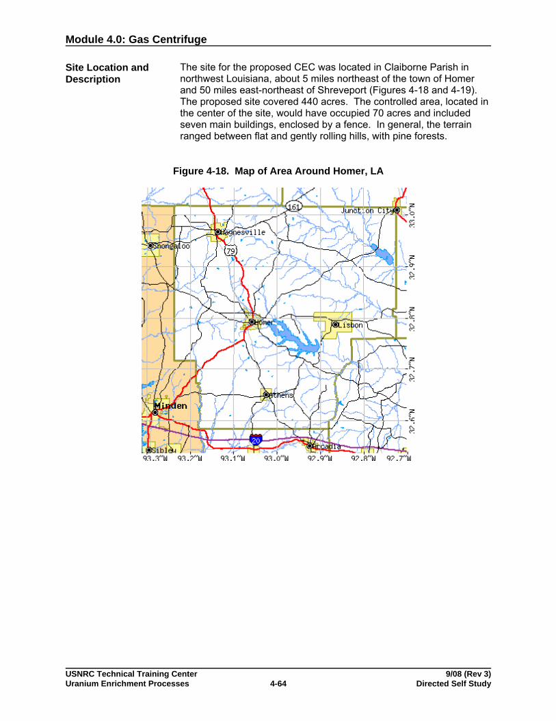
Module 4.0: Gas Centrifuge
USNRC Technical Training Center 9/08 (Rev 3)Uranium Enrichment Processes Directed Self Study4-64
Site Location andDescription
The site for the proposed CEC was located in Claiborne Parish innorthwest Louisiana, about 5 miles northeast of the town of Homerand 50 miles east-northeast of Shreveport (Figures 4-18 and 4-19). The proposed site covered 440 acres. The controlled area, located inthe center of the site, would have occupied 70 acres and includedseven main buildings, enclosed by a fence. In general, the terrainranged between flat and gently rolling hills, with pine forests.
Figure 4-18. Map of Area Around Homer, LA
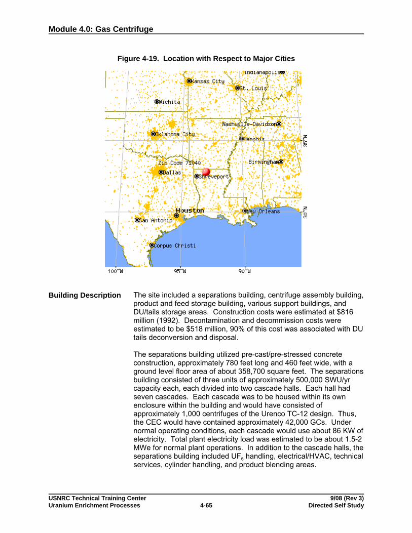
Module 4.0: Gas Centrifuge
USNRC Technical Training Center 9/08 (Rev 3)Uranium Enrichment Processes Directed Self Study4-65
Figure 4-19. Location with Respect to Major Cities
Building Description The site included a separations building, centrifuge assembly building,product and feed storage building, various support buildings, andDU/tails storage areas. Construction costs were estimated at $816million (1992). Decontamination and decommission costs wereestimated to be $518 million, 90% of this cost was associated with DUtails deconversion and disposal.
The separations building utilized pre-cast/pre-stressed concreteconstruction, approximately 780 feet long and 460 feet wide, with aground level floor area of about 358,700 square feet. The separationsbuilding consisted of three units of approximately 500,000 SWU/yrcapacity each, each divided into two cascade halls. Each hall hadseven cascades. Each cascade was to be housed within its ownenclosure within the building and would have consisted ofapproximately 1,000 centrifuges of the Urenco TC-12 design. Thus,the CEC would have contained approximately 42,000 GCs. Undernormal operating conditions, each cascade would use about 86 KW ofelectricity. Total plant electricity load was estimated to be about 1.5-2MWe for normal plant operations. In addition to the cascade halls, theseparations building included UF6 handling, electrical/HVAC, technicalservices, cylinder handling, and product blending areas.

Module 4.0: Gas Centrifuge
USNRC Technical Training Center 9/08 (Rev 3)Uranium Enrichment Processes Directed Self Study4-66
Other buildings would have had metal framed, insulated metal wall onconcrete slab construction. Most UF6 cylinders were to be storedoutside, on paved areas. About 16.2 acres of cylinder storage wasprovided; the majority was for DU/tails cylinders.
Process Description The plant would have been licensed for 5% assay LEU. At the time, itwas anticipated it would produce LEU around 3.5% assay to satisfythe reactor market of the late 1980s/early 1990s (i.e., a lower burnupthan today).
DU feed cylinders would be placed in autoclaves and cold ventedseveral times (to a gas vent system) to remove light gases. Next, thecylinders were heated in autoclaves, using air heated by resistanceheaters. Once liquefied, the cylinder would be hot vented (usuallyonly once) and flow directed to the cascade header piping. Pressureis reduced below atmospheric by valves. Typical feed pressures arebelow 1 psia and typical cascade pressures are on the order of 0.04psia.
The cascade would house the GCs. Each GC consists of a thin-walled, vertical, cylindrically shaped rotor that spins around a centralpost within an outer casing (the stator). The rotor is fabricated fromcarbon-reinforced epoxy and the casing is aluminum. Thestator/housing would be mounted on a specially designed and leveledfloorplate called a flornel. Rotor drag is reduced by maintaining therotor/stator space under a vacuum. An electromagnetic motor driveseach GC, using power at the same frequency as the rotor speed (inrevolutions per second). Each cascade would have a closed loop,cooling water system to remove heat from friction and the motors. Cooling coils at the top and bottom of the rotor also remove heat andprovide a temperature gradient that improves the separations factorand assists enrichment. Feed, product, and DU streams enter andleave the GC via a central post. Each GC includes an exit safetyvalve that closes if there is excess pressure in the GC; separateisolation valves automatically operate in response to a GC failure. Each GC would contain 10 grams of UF6 during normal operations.
The enriched product would be desublimed into cylinders placedinside cold boxes, using cold air as the coolant. DU would bedesublimed into tails cylinders in insulated boxes using a closed-loop,spray water system upon the external surfaces of the cylinder. Thereare separate autoclave and desublimer stations for product samplingand blending. Equipment decontamination would have used solutions of citric acid.
Plant construction, operation, and decontamination anddecommissioning were expected to take 5, 30, and 7 years,respectively. At full production for a given year, the plant would havereceived approximately 4,700 tonnes of feed and produced 870

Module 4.0: Gas Centrifuge
USNRC Technical Training Center 9/08 (Rev 3)Uranium Enrichment Processes Directed Self Study4-67
tonnes of LEU product, with 3,830 tonnes of DU. The calculatedSWU and feed factors are 2 and 5.5, respectively.
Depleted Uraniumand Wastes
Gaseous effluents in the venting system pass through carbon,alumina, and HEPA filters for contaminant removal, followed bymonitoring prior to release. Gas exiting the potentially contaminatedarea of the Separations Building would be treated by HEPA filtrationprior to release. The average annual uranium release to theatmosphere was estimated to be 120 microcuries. The averagerelease rate of HF was expected to be less than 6.5 kg/yr. Thesevalues were found to be well below applicable limits.
Likewise, liquid effluents would be treated prior to release. Aftertreatment, an estimated maximum of 28 microcuries/yr would bereleased. This would be less than 0.5% of the Part 20 limit.
Liquid and gaseous effluent treatment, traps/filters, and personalprotective equipment would be the principal solid radioactive wastes. These were expected to contain less than 100 kg of uranium annually.
The plant would generate about 3,830 tonnes of DU annually. TheNRC concluded there were few uses for the DU and that most of itwould have to be dispositioned as if it were low level waste. LESplanned to have the DUF6 deconverted into DU3O8 at an offsitefacility, followed by disposal in a mine cavity or deeper type ofdisposal unit. DU would be stored onsite until the deconversion anddisposal facilities and arrangements were completed; DU shipmentoffsite was to occur within 15 years of the generation of DU.
Safety NRC reviewed the LES/CEC application using the Atomic Energy Act(as amended), 10 CFR 70 (the older, pre-ISA version), the DraftGeneral Design Criteria for Uranium Enrichment, and NUREG-1391on uranium and UF6 toxicity. Site dispersion analyses were basedupon five years of data collected at Shreveport, LA. The mainhazards were found to involve liquid UF6 in quantities greater than1,100 kg (buoyant releases) and 119 kg of UF6 in non-buoyantreleases (e.g., desublimers, cascade hall piping, and moderate leaksfrom cylinders). Staff concluded the Separations Building wouldadequately resist design basis tornados and earthquakes (10,000 and500 year return periods, respectively), and protect liquid UF6containing equipment, such as the autoclaves. The generalapproaches and safety programs were found to be consistent withaccepted practices and ALARA. The maximum exposed individualwould receive no more than approximately 0.6 mrem/yr CEDE from allpathways at 400 meters. Potential accidents involving liquid UF6 werefound to be the greatest hazards, such as in the autoclaves (fromheater malfunctions) and cylinder storage areas (e.g., from fires; LESdid not plan to move liquid cylinders outside of the autoclaves).
Module 4.0: Gas Centrifuge
USNRC Technical Training Center 9/08 (Rev 3)Uranium Enrichment Processes Directed Self Study4-68
Safety controls on autoclaves and fuel limits on cylinder carriers in theyards would address these hazards.
Staff analyses on DU disposition indicated that near-surface, shallowland disposal would result in ingestion doses far above the 25mrem/yr limit. Staff concluded disposal in a site deeper than normalshallow land disposal practice (e.g., a mine cavity) would experiencereducing leaching chemistry that would not exceed the 25 mrem/yrlimit. However, subsurface disposal, such as in a mine, does notcurrently exist.
Staff Assessment The staff concluded the proposed facility presented no undue riskbased upon the applicant’s submissions and commitments. Staffproposed several conditions related to facility inspection and radiationmonitoring instrumentation.
Licensing/Status LES was concerned about the numerous delays and the non-safetyissue focus of the Commission and ASLB interactions. LES saw noreason to revisit the Final EIS given its conclusion of no undue impactand safe operation of the Urenco facilities in Europe. Expendedlicensing costs rose to about $34 million. LES ultimately concludedthe Commission/ASLB interactions appeared endless and withdrewthe application on April 22, 1998.
Module 4.0: Gas Centrifuge
USNRC Technical Training Center 9/08 (Rev 3)Uranium Enrichment Processes Directed Self Study4-69
Learning Objective
When you finish this section, you will be able to:
4.1.6 Summarize Case Study 2: Summary of Proposed National Enrichment Facility.
CASE STUDY 2:NATIONALENRICHMENTFACILITY
Overview On December 12, 2003, Louisiana Energy Services (LES) submitted,to the NRC, an application requesting a license, under 10 CFR Parts30, 40, and 70, to possess and use byproduct, source, and specialnuclear material (SNM) in a gas centrifuge uranium enrichmentfacility. LES proposes that the facility be located in Lea County, NewMexico, and have a nominal capacity of 3 million separative workunits (SWUs). The facility will possess natural, depleted, and enricheduranium, and will enrich uranium up to a maximum of 5 percenturanium-235. The applicant also requested a facility clearance forclassified information, under 10 CFR Part 95.
The NRC staff conducted its safety review in accordance withNUREG-1520, “Standard Review Plan for the Review of a LicenseApplication for a Fuel Cycle Facility.” The staff’s safeguards reviewinvolved reviews of the applicant’s Fundamental Nuclear MaterialsControl Plan (FNMCP); the Physical Security Plan, which includestransportation security; and a “Standard Practice Procedures Plan forthe Protection of Classified Matter.” The staff also reviewed theapplicant’s Quality Assurance Program Description and EmergencyPlan. Where the applicant’s design or procedures should besupplemented, the NRC staff has identified license conditions toprovide assurance of safe operation. The staff’s safety evaluationreport is NUREG-1827. The applicant also submitted anEnvironmental Report, which was used to prepare, in a separatedocument, an Environmental Impact Statement for the facility(NUREG-1790).
The NRC issued the license to LES and construction has commencedon the facility.
Site Location andDescription
The proposed site is in Southeastern New Mexico in Lea County,approximately 1.6 km (1 mi) west of the New Mexico–Texas border onthe north side of New Mexico Highway 234. Figure 4-20 displays thelocation, and Figure 4-21 denotes an artist’s representation of thefacility. Andrews County, Texas, lies across the border from the site.

Module 4.0: Gas Centrifuge
USNRC Technical Training Center 9/08 (Rev 3)Uranium Enrichment Processes Directed Self Study4-70
The site is about 8 km (5 mi) east of Eunice, New Mexico, and 32 km(20 mi) south of Hobbs, New Mexico. The site is 220 ha (543 acres) insize and is located within County Section 32, Township 21 South,Range 38 East. The site is owned by Lea County. The proposed siteis relatively flat with elevations between 1033 and 1045 m (3,390 to3,430 ft) above sea level. The site slopes to the southwest, isundeveloped, and is used for domestic livestock grazing.
Figure 4-20. Proposed Facility Location

Module 4.0: Gas Centrifuge
USNRC Technical Training Center 9/08 (Rev 3)Uranium Enrichment Processes Directed Self Study4-71
Figure 4-21. Artist Representation of the Proposed Facility
Building Description The site included three separations buildings, centrifuge assemblybuilding, product and feed storage building, various support buildings,and DU/tails storage areas. Construction costs were estimated at$1.5 billion (2006). Decontamination and decommissioning costswere estimated at $942 million; $131 million for structures/equipment,$622 million for DU/Tails (conversion and disposal), and $188 millioncontingency (2004 values).
The proposed plant will be constructed to have three SeparationsBuilding Modules, each having two Cascade Halls, with eachCascade Hall having eight cascades. Each Separations Buildingconsists of a UF6 Feed System, Cascade Systems, a Product Take-offSystem, and a Tails Take-off System. The plant also has a ProductLiquid Sampling System and a Product Blending System.
Each Separations Building Module includes two cascade halls. EachSeparations Building Module has a uranium hexafluoride handlingarea and a process services area. A Separations Building Module is170 m (557.75 ft) long, 67.9 m (222.75 ft) wide, and 13 m (42.7 ft)high, and has 12,703 m2 (137,025 ft2) of space. The TechnicalServices Building is a two-story building with 9,192 m2 (98,942 ft2) ofspace. The Cylinder Receipt and Dispatch Building is 246.2 m (807.75ft) long, 45.9 m (150.6 ft) wide, and 13 m (42.7 ft) high, and has11,300 m2 (121,638 ft2) of space. The Centrifuge Assembly Buildingis 195.5 m (641.4 ft) long, 50.9 m (167 ft) wide, and 11 to 16 m (36.1

Module 4.0: Gas Centrifuge
USNRC Technical Training Center 9/08 (Rev 3)Uranium Enrichment Processes Directed Self Study4-72
to 52.5 ft) high, and has 11,364 m2 (122,322 ft2) of space. TheBlending and Liquid Sampling Area is 33.5 m (109.9 ft) long, 45.9 m(150.6 ft) wide, and 10 m (32.8 ft) high, and has 1,538 m2 (16,555 ft2)of space.
Process Description The proposed facility is licensed to produce LEU with a maximumassay of 5%. The plant itself is designed for 6% enrichment andhigher enrichments may be possible, but these would require licenseamendments. It is anticipated that the facility will produce LEU at ornear its license limit of 5% assay.
The enrichment processes and equipment analyzed as part of the ISAprocess are described in the LES ISA Summary, Section 3.4. Theenrichment systems are comprised of the Uranium Hexafluroide (UF6)Feed System, Cascade System, Product Take-off System, and TailsTake-off System. Major support systems include the Product BlendingSystem, Product Liquid Sampling System, and Contingency DumpSystem. Systems used to support the enrichment process and thehandling of UF6 are the Gaseous Effluent Vent System (GEVS),Centrifuge Test Facility and Centrifuge Post Mortem Facility, andMaterial Handling. A subsection containing information pertaining tothe functional description, major components, design description,interfaces, design and safety features, operating limits,instrumentation, and IROFS is provided for each of the 10 enrichmentand supporting systems.
The process function is to enrich the amount of the 235U isotope inUF6 from 0.711 weight percent up to a maximum of 5.0 weight percentthrough a mechanical centrifuge separation process. The applicationand issued license are based upon the Urenco TC-12 GC; LES hasstated they may substitute a TC-21 model for one or more of thecascades after construction has initiated, based upon enrichmentmarket demand. The TC-21 has the same footprint as the TC-12centrifuge but double the height, which effectively doubles itsenrichment (SWU) capacity and increases the enrichment capacity ofthe entire facility. Such a modification would require a licenseamendment.
Naturally occurring uranium will be received from a conversion facilityin the form of UF6 shipped in Type 48Y or 48X cylinders qualified toAmerican National Standard Institute (ANSI) Standard N14.1 (ANSI,1995). The UF6 will be in a solid state under vacuum. The UF6 feedsystem will heat the cylinder to 53°C (127°F) to sublime the UF6 into agas. The feed purification system removes light gas components fromthe feed to a specified level prior to admittance to the cascade inorder to protect the centrifuges and enhance efficiency. At the feedpurification Low Temperature Take-off Stations, Type 48X or 48Ycylinders are cooled to -25°C (-13°F). Gaseous UF6 enters thecylinders and desublimes into the solid phase. UF6 coldtraps,aluminum oxide (Al2O3) traps, and vacuum pumps are used to

Module 4.0: Gas Centrifuge
USNRC Technical Training Center 9/08 (Rev 3)Uranium Enrichment Processes Directed Self Study4-73
transfer residual light gas to the GEVS. The traps remove any UF6 orhydrogen fluoride (HF) from the effluent stream.
From purification, UF6 is transferred to the cascades whereenrichment occurs. The cascades are operated under a significantvacuum (about 65 mbar or 0.09 psia) to assure the UF6 does notdesublime back into a solid state at ambient temperatures. Theproposed design uses the TC-12 centrifuge – some 84,000 would beinstalled and only a small number would fail over the lifetime of theplant. Use of the larger TC-21 centrifuge would reduce the number ofGCs installed or increase the plant’s capacity; Urenco has not made adecision yet regarding use of the larger TC-21 GC at this facility. Useof the TC-21 would require a license amendment from the NRC. Thecascade systems separates the UF6 feed stream into a productstream and a tails stream. The product stream is routed to theProduct Take-off System, where it is transported by vacuum pumps tothe Product Low Temperature Take-off Station. These stations areoperated at -25°C (-13°F) and the UF6 desublimes into the solid forminside a Type 30B or 48Y cylinder. The Type 30B cylinder is used forfinal product, while the Type 48Y cylinder is used for future blendingoperations. Any light gas impurities are purged through cold trapsfollowed by product vent vacuum pump/chemical trap sets. The TailsTake-off System withdraws the depleted UF6 stream and provides ameans to withdraw UF6 from the centrifuge cascades under abnormalconditions. The UF6 is routed to a Low Temperature Take-off Stationoperated at -25°C (-13°F). The gaseous UF6 is desublimed into a solidform inside a Type 48Y cylinder.
The Product Blending system is used to provide a specific enrichmentof 235U by blending UF6 at two different enrichment levels. Thedonor stations can handle Type 30B and 48Y product cylinders. TheUF6 is sublimed back into a gas and transported to a BlendingReceiver Station containing an empty Type 30B cylinder operated at -25°C (-13°F), where the UF6 desublimes back into a solid form.
The only system at the facility that changes solid UF6 into liquid UF6 isthe Product Liquid Sampling System. A filled Type 30B cylinder isplaced in an autoclave that is heated to 70°C (158°F) by electricheaters. When the pressure reaches +2.5 bar (36.3 psia), thetemperature is stabilized for about 16 hours to allow homogenizationprior to sampling. The sample bottles are connected to the cylinder viaa header, all located within the confines of the autoclave. The mainsafety feature of the autoclave is to provide a secondary confinementbarrier in the event of a UF6 leak. All Type 30B cylinders are requiredto meet ANSI N14.1 requirements, which include a cylinder designpressure of 1380 kPa (200 psi) and testing to 2760 kPa (400 psi).
Section 3.5 of the ISA Summary emphasizes capacities,redundancies, and other provisions for coping with routine and non-routine events. The system descriptions include functionalrequirements, design capacities, system interfaces, and descriptions
Module 4.0: Gas Centrifuge
USNRC Technical Training Center 9/08 (Rev 3)Uranium Enrichment Processes Directed Self Study4-74
of major components. Operational characteristics and safetyconsiderations are also described.
Plant construction, operation, and decontamination anddecommissioning were expected to take 5, 30, and 9 years,respectively. Production would start incrementally, as each hall orseparations building is completed (e.g., in 500,000 or 1,000,000SWU/yr increments). At full production for a given year, the plantwould have received approximately 8,600 tonnes of feed (about 70048Y cyinders) and produced 800 tonnes of LEU product, with 7,800tonnes of DU. The calculated SWU and feed factors are about 4 and11, respectively. Substitution of the larger TC-21 GC for the TC-12GC would require a license amendment and double the associatedmass and SWU values.
Depleted Uraniumand Wastes
Gaseous effluents in the venting system pass through carbon,alumina, and HEPA filters for contaminant removal, followed bymonitoring prior to release. Gas exiting the potentially contaminatedarea of the Separations Building would be treated by HEPA filtrationprior to release. Gaseous airborne effluents will be released from theproposed facility. The applicant estimates that less than 10 grams(0.35 ounces (oz); 240 microcuries) of uranium and less than 1kilogram (kg) (2.2 pounds (lbs)) of HF will be released annually in 2.47× 10⁹ cubic meters of air discharge. The CEDE was estimated to bebelow 0.1 mrem/yr to the MEI. Worker doses were estimated toaverage 20-25 mrem/yr, roughly comparable to the doses at theUrenco facilities in Europe. The effluents are significantly below 10CFR Part 20 and U.S. Environmental Protection Agency NationalEmission Standards for Hazardous Air Pollutants (NESHAPs)airborne release limits.
The applicant estimated the maximum individual CEDE for liquideffluents during normal operations at the proposed facility. Theapplicant estimated maximum annual quantity of radiological materialin liquid effluent would be 14.4 MBq (390 microCi) of uranium asdischarge to the Treated Effluent Evaporative Basin (TEEB) (LES,2005b). There are no offsite releases to any surface waters or publiclyowned treatment works. Therefore, the release pathway the applicantassumed is airborne resuspension of particulate matter from thebottom of the basin, if waste water should evaporate. The applicantevaluated the dose for the 30th year of operations, which represents arealistically conservative upper bound on the amount of uraniumavailable for resuspension and atmospheric dispersion. As noted inSection 8.7 of the applicant’s ER, potential radiological impacts fromoperation of the proposed facility would result from controlled releasesof small quantities of uranium hexafluoride (UF6) during normaloperations. The CEDE to the maximally exposed member of thepublic located at the south side of the controlled area boundary,resulting from the annual release to the atmosphere of 2.1 MBq (56:Ci) of uranium from the TEEB, would be less than

Module 4.0: Gas Centrifuge
USNRC Technical Training Center 9/08 (Rev 3)Uranium Enrichment Processes Directed Self Study4-75
0.017 :Sv (0.0017 mrem) per year if the TEEB is dry only 10 percentof the year (LES, 2005b). If the TEEB is dry the entire year, theCEDE to the maximally exposed member of the public located at thesouth side of the controlled area boundary would be less than 0.17 :Sv (0.017 mrem) per year. The estimated maximum public doseis also well below the 0.1 mSv (10-mrem) ALARA constraint on liquidemissions described in 10 CFR 20.1101 (e.g., less than 2 percent).
Wastes expected to be generated include non-hazardous industrial,Class A radioactive, hazardous, and mixed wastes. Constructionwastes will also be generated in construction of the plant. Radioactivewastes approximate 12 te/yr and will be disposed of at properlylicensed low-level radioactive waste disposal facilities. Hazardouschemical wastes will be properly treated and disposed of at permittedtreatment and disposal facilities. Mixed low-level radioactive andchemically hazardous wastes will be treated and disposed of atfacilities having the proper licenses and permits for these wastes. Allquantities are small.
Depleted uranium tails will be stored on-site on the UraniumByproduct Cylinder (UBC) pad until they are transferred to anotherlicensee for commercial use or they are designated for disposal aswaste. If designated as waste, the applicant is proposing to use eithera commercial disposition path or the U.S. Department of Energy(DOE) disposition path set out in the USEC Privatization Act of 1996.As part of an agreement with the State of New Mexico, LES hascommitted to not store any depleted uranium cylinder for longer thanfifteen years, not store more than 5,016 DU cylinders onsite at anytime, and increase the contingency to 50% if more than 4,000cylinders are in storage at any one time.
LES estimated that the facility will generate 132,942 MT of depleteduranium over a nominal 30 years of production, and did not reducethe estimate of depleted uranium based on the planned operationsapproach where production would actually end 5 years earlier (note:this estimated DU quantity value varies between documents). Theapplicant identified the waste processing and disposal cost of UF6tails as $4.68 per kilogram of uranium (kg U) or $4,680 per metric tonof uranium (MTU). This cost is based on the total of the three costcomponents that make up the total disposition cost for DUF6 (i.e.,deconversion, disposal, and transportation). The deconversion costwas based on proprietary information on a previously proposedprivate deconversion plant using the Cogema dry conversion processproducing U3O8 and aqueous hydrogen fluoride (HF). The proposedprocess was the same as the plant Cogema has been operating inPierrelatte, France for 20 years. The cost estimate was adjusted toaccount for differences in planned operating capacities, Euros-to-dollars conversion, and other costs associated with “Americanization.”“Americanization” refers to costs to obtain regulatory approval andcosts to convert European equipment standards to standards used inthe United States. These cost estimates used a proprietary Urenco

Module 4.0: Gas Centrifuge
USNRC Technical Training Center 9/08 (Rev 3)Uranium Enrichment Processes Directed Self Study4-76
business study of a proposed 3,500 Metric Tons (MT) U/yeardeconversion plant for the Capenhurst site. The study was based on aCogema response to a Urenco request for proposal. LES modified theCogema information to reflect a 7,000 MT U/year capacity by doublingthe operating costs and by adding funds to reflect the increasedcapital and construction costs of a larger capacity plant consideringthe shared nature of some systems. Additional funds were also addedfor Americanizing the design and for licensing. The Cogema proposalassumed that HF would be sold commercially and did not include thecosts to neutralize aqueous HF to calcium fluoride. NRC staffconsidered that neutralization would have no effect on the overalldeconversion costs because those costs would be balanced by theelimination of costs for equipment for storing HF prior to commercialsale. The cost of disposing the calcium fluoride ($0.02/kg U) wasincluded in the estimate.
The transportation and disposal costs were based on estimatesprovided by vendors of transportation and disposal services (LES,2005a). Transportation costs were based on an estimate fromTransportation Logistics International. This transportation estimate($0.85/kg U) was independent of distance. The disposal cost of$1.14/kg U for depleted uranium oxides was based on an estimateprovided by Waste Control Specialists. Staff compared the WasteControl Specialists estimate to an estimate for disposal ofdecommissioning wastes the applicant had obtained from Envirocareof Utah and found it to be consistent. The Envirocare disposalestimate for decommissioning waste was $2.12/m3 ($75/ft3) (LES,2004). For the disposal of U3O8, the equivalent disposal cost atEnvirocare is $1.07/kg U. Further, the applicant submitted anestimate for tails disposition from the U.S. Department of Energy(DOE) (DOE, 2005) as additional evidence of the reasonableness oftheir estimate. The DOE estimate included conversion, transportation,storage, disposal, and decommissioning costs of the conversionfacility and totaled $3.34/kg DUF6 ($4.91/kg U) in 2004 dollars. This isless than 5 percent of the difference in the applicant’s estimate of$4.68/kg U. Staff considers that the DOE estimate provides additionalassurance that the applicant’s estimate of depleted uraniumdisposition costs is reasonable.
Safety LES submitted, to the U.S. NRC, an application requesting a license,under 10 CFR Parts 30, 40, and 70, to possess and use byproduct,source, and special nuclear material (SNM) in a gas centrifugeuranium enrichment facility, located in Lea County, New Mexico, andhave a nominal capacity of 3 million separative work units(SWUs). The facility will possess natural, depleted, and enricheduranium, and will enrich uranium up to a maximum of 5 percenturanium-235. The applicant also requested a facility clearance forclassified information, under 10 CFR Part 95.
Module 4.0: Gas Centrifuge
USNRC Technical Training Center 9/08 (Rev 3)Uranium Enrichment Processes Directed Self Study4-77
The NRC staff conducted its safety review in accordance withNUREG-1520, “Standard Review Plan for the Review of a LicenseApplication for a Fuel Cycle Facility.” The staff’s safeguards reviewinvolved reviews of the applicant’s Fundamental Nuclear MaterialsControl Plan (FNMCP); the Physical Security Plan, which includestransportation security; and a “Standard Practice Procedures Plan forthe Protection of Classified Matter.” The staff also reviewed theapplicant’s Quality Assurance Program Description and EmergencyPlan. Where the applicant’s design or procedures should besupplemented, the NRC staff identified license conditions to provideassurance of safe operation.
The LES design approach minimizes the presence of liquid UF6 in thefacility. This, combined with the low operating pressures inherent inGC facilities greatly reduces source terms of routine operations andpotential accidents. Routine exposures were estimated in the 20-25mrem/yr range for workers and 0.1 mrem/yr or less for the MEI.
LES would use ASTM methods to sample a cylinder. These methodsinvolve liquefaction of the UF6 in an autoclave. This is the only part ofthe operations that involve liquid UF6. A potential accident involvingthe release of this material was found to have the highestconsequence.
The health and environmental consequences of this accident arehigh. A facility worker in the vicinity of the blending donor stationwould, within seconds, be exposed to lethal UF6, UO2F2, and HFconcentrations. The environmental consequences are higher than the5.4 U mg/m3 threshold for an intermediate consequence. Anindividual located at the CAB in the southwest sector would sufferhigh consequences from both uranium and HF exposure. Thecollective dose to the offsite population in the north sector indicates arisk of several LCFs in the population in the years after the accident. In accordance with the performance requirements of Part 70, SubpartH, the applicant has identified IROFS to reduce the risk to the facilityworkers, the public, and the environment from the effects of thisaccident. To prevent this accident, the applicant will rely on fail-safehardwired high-temperature heater trips and redundant independentfail-safe capillary high temperature heater trips. Each control will betested annually to ensure its availability and reliability to serve itsintended safety function on demand. The purpose of these controls isto ensure that the accident is highly unlikely to occur. In addition,there have been no similar heater control failures at the Urencofacilities in Europe in over 30 years of operation.
Staff concluded the Separations Building would adequately resistdesign basis tornados and earthquakes (100,000 [F3] and 10,000[0.15g] year return periods, respectively), and protect UF6 containingequipment. The general approaches and safety programs were foundto be consistent with accepted practices and ALARA.
Module 4.0: Gas Centrifuge
USNRC Technical Training Center 9/08 (Rev 3)Uranium Enrichment Processes Directed Self Study4-78
Staff Assessment The NRC staff concluded that the applicant’s descriptions,specifications, and analyses provide an adequate basis for safety andsafeguards of facility operations and that operation of the facility didnot pose an undue risk to worker and public health and safety.
License conditions have been added to the license to ensure thatIROFS boundaries will be defined using the applicant’s IROFSboundary definition procedure and that the applicant will submitlicense amendment requests if digital instrumentation and controls areused in IROFS . In the facility SAR, LES provided preliminary designbasis information for I&C systems that it identified as IROFS for thefacility. The design information is at the system functional level.Individual components and vendors had not yet been selected. Basedon the staff’s review of the SAR, supporting information provided bythe applicant, and the applicant’s commitments to the industrystandards and guidance cited in the sections above for I&C systems,the staff found that the preliminary design meets the requirements of10 CFR 70.61 and 70.64(a)(10).
Given that these conclusions were based on preliminary designinformation and the possibility that the applicant may choose toimplement design changes as discussed in the SER section on I&C,the staff imposed a license condition to ensure that the final design isadequate and acceptable to the staff. Specifically, the followingcondition will be included in the license:
“Currently, there are no IROFS that have been specified as usingsoftware, firmware, microcode, PLCs, and/or any digital device,including hardware devices which implement data communicationprotocols (such as fieldbus devices and Local Area Networkcontrollers), etc. Should the design of any IROFS be changed toinclude any of the preceding features, the licensee shall obtainCommission approval prior to implementing the change(s). Thelicensee’s design change(s) shall adhere to accepted best practices insoftware and hardware engineering, including software qualityassurance controls as discussed in the in the Quality AssuranceProgram Description throughout the development process and theapplicable guidance of the identified industry standards and regulatoryguides as specified in SAR Chapter.
“If any changes result in IROFS requiring operator actions, thelicensee shall conduct a human factors engineering review of thehuman-system interfaces using the applicable guidance in NUREG-0700, “Human-System Interface Design Review Guidelines,” Revision2, dated May 2002, and NUREG-0711, “Human Factors EngineeringProgram Review Model,” Revision 2, dated February 2004.”
Licensing/Status The license has been issued and construction has commenced.
Module 4.0: Gas Centrifuge
USNRC Technical Training Center 9/08 (Rev 3)Uranium Enrichment Processes Directed Self Study4-79
Learning Objective
When you finish this section, you will be able to:
4.1.7 Summarize Case Study 3: Summary of proposed American Centrifuge Plant.
CASE STUDY 3:AMERICANCENTRIFUGEPLANT
Overview On August 23, 2004, USEC Inc. (the applicant) submitted, to the U.S.Nuclear Regulatory Commission (NRC), an application requesting alicense, under 10 CFR Parts 30, 40, and 70, to possess and usebyproduct, source, and special nuclear material (SNM) in a gascentrifuge uranium enrichment facility. The applicant proposes thatthe facility be located on the U.S. Department of Energy (DOE)reservation in Piketon, Ohio, and have a nominal capacity of 3.5million separative work units (SWUs). The facility will possess natural,depleted, and enriched uranium, and will enrich uranium up to amaximum of 10 percent uranium-235. The applicant also requested afacility clearance for classified information, under 10 CFR Part 95.
NRC staff conducted its safety review in accordance with NUREG-1520, “Standard Review Plan for the Review of a License Applicationfor a Fuel Cycle Facility.” The staff’s safeguards review involvedreviews of the applicant’s Fundamental Nuclear Material Control Plan(FNMCP); the Physical Security Plan, which includes transportationsecurity; and a “Standard Practice Procedures Plan for the Protectionof Classified Matter.” The staff also reviewed the applicant’s QualityAssurance Program Description and Emergency Plan. Where theapplicant’s design or procedures should be supplemented, NRC staffhas identified license conditions to provide assurance of safeoperation. The staff’s safety evaluation report is NUREG-1851. Theapplicant also submitted an Environmental Report, which was used toprepare, in a separate document, an Environmental Impact Statementfor the facility (NUREG-1834). USEC identified the potential toincrease the capacity at the site to 7 MSWU/yr at a later time; such anexpansion would require a license amendment but the EIS studieswere conducted at the 7 MSWU/yr capacity level.
The NRC has issued the license to USEC and preliminaryconstruction has commenced.

Module 4.0: Gas Centrifuge
USNRC Technical Training Center 9/08 (Rev 3)Uranium Enrichment Processes Directed Self Study4-80
Site Location andDescription
In Section 1.1 of the license application, the applicant provides asummary description of the proposed gas centrifuge uraniumenrichment plant and processes. The applicant is proposing to use agas centrifuge enrichment process to enrich uranium. The proposedplant, known as the American Centrifuge Plant (ACP), will have anominal production capacity of 3.5 million separative work units(SWUs). The process uses uranium in the chemical form of uraniumhexafluoride (UF6). Gaseous UF6 enters a high-speed rotor atsubatmospheric conditions where centrifugal forces press the heavierisotope of uranium, uranium-238 (U-238), to the outer wall of the rotor.The lighter isotope, uranium-235 (U-235), remains slightly closer tothe center, away from the rotor wall. Internal scoops are used tocollect the heavier and lighter fractions and circulate them to othercentrifuges piped in a cascade arrangement.
The applicant has proposed that the ACP be located at the U.S.Department of Energy’s (DOE’s) Portsmouth Gaseous Diffusion Plant(PORTS) reservation in Piketon, Ohio, in refurbished existingbuildings, newly constructed facilities, and grounds to be leased fromDOE by the United States Enrichment Corporation, a subsidiary of theapplicant. Figure 4 -22 provides a view of the existing site; Figure 4-23 superimposes the proposed facilities on the site. The applicantwill in turn, sub-lease the ACP buildings and grounds from the UnitedStates Enrichment Corporation.
NRC will not issue a license until the lease is signed and NRCconfirms that the contents of the lease agreements do not contradictany license conditions or considerations and assumptionsdocumented in the applicant’s LA and its supporting documents andNRC’s licensing basis as documented in this Safety Evaluation Report(SER), Final Environmental Impact Statement, and their supportingdocuments.
Building Description The ACP facility will consist of multiple buildings, each one of whichwill perform a specific function. The current (Summer 2007) estimatedcost for the facility is $2.3 billion. The plant capacity has been revisedto 3.8 MSWU/yr. A listing of selected buildings and their specificfunctions follows:
1. Two existing Process Buildings, X-3001 and X-3002, which willbe refurbished to:
(a) house operating centrifuge machines;(b) associated process piping; (c) instrumentation and controls; (d) computer systems; and (e) auxiliary support equipment.
The X-3001 and X-3002 buildings will be similar in construction,layout, and design.

Module 4.0: Gas Centrifuge
USNRC Technical Training Center 9/08 (Rev 3)Uranium Enrichment Processes Directed Self Study4-81
2. The facilities will include the existing X-3012 Process SupportBuilding to provide operational control and maintenance of theequipment in the Process Buildings.
Figure 4-22. Existing Portsmouth Site (view from Northeast looking Southwest; existing buildings for the proposed GC facility are just above the photograph’s center andright)

Module 4.0: Gas Centrifuge
USNRC Technical Training Center 9/08 (Rev 3)Uranium Enrichment Processes Directed Self Study4-82
Figure 4-23. Proposed GC Facility at Portsmouth (view from Northwest looking Southeast; as noted in the text, some buildings are pre-existing)
3. The existing X-3346 Feed and Customer Services Building willprovide for process feed, sampling, and product transferrequirements. The Feed Area of the building will houseelectrically heated feed ovens to provide the UF6 feed. UF6 feedwill be processed through purification burp systems before beingfed into the process piping in X-3001 and X-3002. A bridge cranewill be used to place feed cylinders on railcarts.
4. The Customer Services Area of the X-3346 building will housethe back-end equipment necessary for sampling and transfer ofUF6 material to customer cylinders. The Customer Services Areawill be the only area where liquid UF6 may be present. In thisbuilding, UF6 product contained in 10-ton cylinders will beliquefied in electrically heated containment autoclaves for thepurpose of sampling and transferring the UF6 into 2.5 toncustomer cylinders.
5. The new X-3346A Feed and Product Shipping and ReceivingBuilding will serve as the focal point for the receipt and shippingof natural and enriched uranium in U.S. Department ofTransportation approved containers.

Module 4.0: Gas Centrifuge
USNRC Technical Training Center 9/08 (Rev 3)Uranium Enrichment Processes Directed Self Study4-83
6. The new X-3356 Product and Tails Withdrawal Building willhouse the equipment for withdrawal of the enriched and depletedUF6 from the X-3001 and X-3002 Process Buildings. In thisbuilding, UF6 product will be desublimed into cold traps beforetransfer into 10-ton product cylinders via sublimation in the coldtraps, followed by desublimation in the cylinders. Tails withdrawalwill be performed via compression and direct desublimation of theUF6 into 14-ton tail cylinders.
7. The X-7725 Recycle/Assembly Facility will provide an area wherecentrifuge machines can be manufactured, assembled, tested,and maintained.
8. The X-7726 Centrifuge Training and Test Facility will provideareas to receive and test centrifuge components, and toassemble and repair the centrifuges. The facility may also beused as a machine assembly training area for the ACP.
9. The X-7727H Interplant Transfer Corridor will provide a protectedpathway for transporting centrifuge machines between the X-7725 or X-7726 buildings and the Process Buildings.
10. Cylinder Storage Yards will support the movement and storage ofcylinders containing UF6 material.
11. The X-2232C Interconnecting Process Piping connects the X-3346 Building to the X-3001 and X-3002 Process Buildings andwill be external to the primary facilities.
12. Secondary facilities for the ACP will include data processingfacilities, emergency response facilities, electrical distributionsystems, security fencing and portals, a pumphouse, an airgeneration plant, a cooling tower, a boiler system, a trainingfacility, a maintenance facility, storage facilities, and wasteaccountability facilities.
Process Description The ACP will be comprised of various buildings/facilities and areas onthe U. S. Department of Energy (DOE) reservation in Piketon, Ohio.The ACP will primarily utilize existing buildings and facilities whichwere part of DOE’s Gas Centrifuge Enrichment Plant, built in the early1980s, but will also use newly constructed buildings and facilities. Thefacility the applicant proposes will be divided into the followingoperations:
• Receipt of UF6• Feeding of UF6 into the enrichment process• Enrichment processing using the cascade centrifuge machines• Enriched and depleted UF6 withdrawal• UF6 sampling to ensure it meets customer specifications• UF6 product material transfer into customer cylinders

Module 4.0: Gas Centrifuge
USNRC Technical Training Center 9/08 (Rev 3)Uranium Enrichment Processes Directed Self Study4-84
• Loading of UF6 cylinders for shipment to customers• Handling of waste generated from the entire process
Cylinders containing feed UF6, cylinders containing enriched product,and customer shipping cylinders and overpacks, as well as newand/or cleaned empty cylinders, will be received onsite through the X-3346A building. The cylinders will be off-loaded, weighed, andtransferred to the appropriate cylinder storage areas.
The major equipment used in the UF6 feed process (X-3346 building)will be the feed ovens. Natural UF6 will be delivered to the plant inAmerican National Standards Institute (ANSI) N14.1, “NuclearMaterials - Uranium Hexafluoride - Packaging for Transport” standardtype 14-ton international transit cylinders. Feed cylinders will beloaded into the electrically heated feed ovens; vented for removal oflight gases, primarily consisting of air and hydrogen fluoride (HF); andheated to sublime the solid UF6. Solid UF6 left in the cylinder after thefeed operation will be recovered by being “heeled” to a freezer-sublimer in the Burp System.
The cascade centrifuge machines will be contained in the ProcessBuildings (X-3001 and X- 3002). UF6 feed material will be supplied tothe process from the Feed and Customer Service Building (X-3346)via heated interconnecting piping at subatmospheric pressure. Sinceindividual centrifuges will not be able to produce the desired productand tails concentration in a single step, the centrifuges will begrouped together in series and in parallel to form arrays known ascascades. Figures 4-24 and 4-25 show cascades using DOE GCs –the ACP cascades would be similar. A centrifuge consists of avertical, cylindrically-shaped rotor that spins within an outer casing. Asthe UF6 feed enters the cascade, it will be mixed with material alreadyin the cascade and separated into enriched and depleted materialstreams.
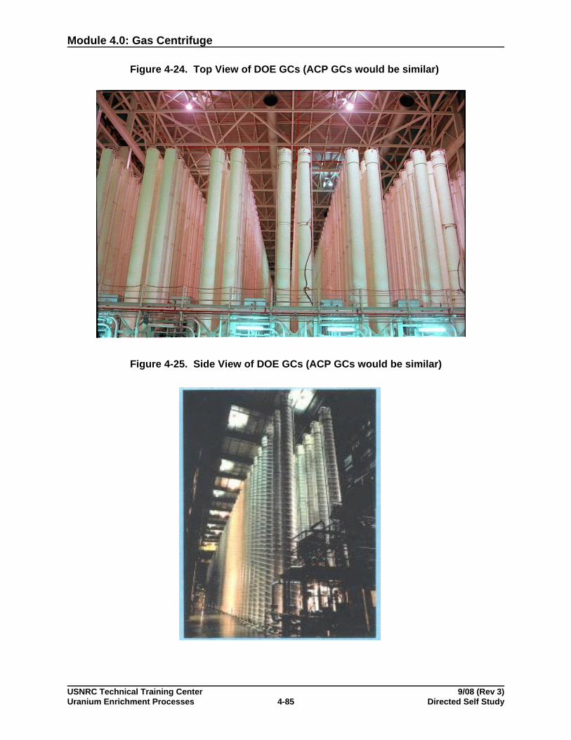
Module 4.0: Gas Centrifuge
USNRC Technical Training Center 9/08 (Rev 3)Uranium Enrichment Processes Directed Self Study4-85
Figure 4-24. Top View of DOE GCs (ACP GCs would be similar)
Figure 4-25. Side View of DOE GCs (ACP GCs would be similar)
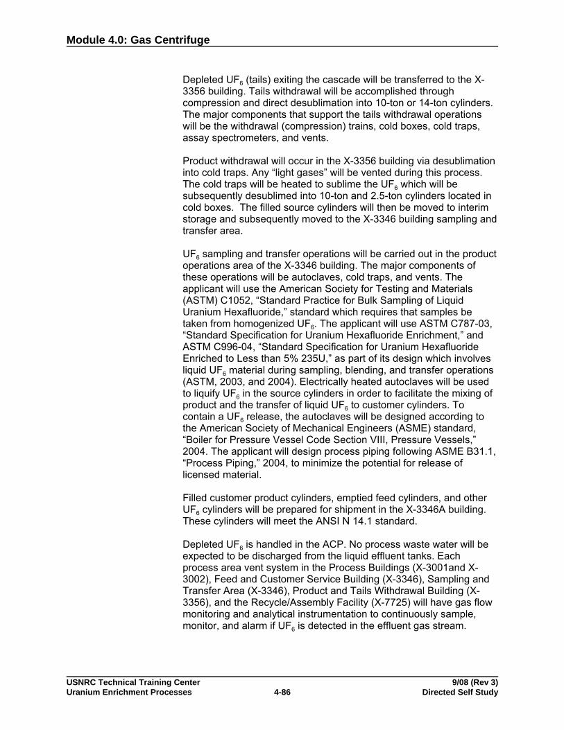
Module 4.0: Gas Centrifuge
USNRC Technical Training Center 9/08 (Rev 3)Uranium Enrichment Processes Directed Self Study4-86
Depleted UF6 (tails) exiting the cascade will be transferred to the X-3356 building. Tails withdrawal will be accomplished throughcompression and direct desublimation into 10-ton or 14-ton cylinders.The major components that support the tails withdrawal operationswill be the withdrawal (compression) trains, cold boxes, cold traps,assay spectrometers, and vents.
Product withdrawal will occur in the X-3356 building via desublimationinto cold traps. Any “light gases” will be vented during this process.The cold traps will be heated to sublime the UF6 which will besubsequently desublimed into 10-ton and 2.5-ton cylinders located incold boxes. The filled source cylinders will then be moved to interimstorage and subsequently moved to the X-3346 building sampling andtransfer area.
UF6 sampling and transfer operations will be carried out in the productoperations area of the X-3346 building. The major components ofthese operations will be autoclaves, cold traps, and vents. Theapplicant will use the American Society for Testing and Materials(ASTM) C1052, “Standard Practice for Bulk Sampling of LiquidUranium Hexafluoride,” standard which requires that samples betaken from homogenized UF6. The applicant will use ASTM C787-03,“Standard Specification for Uranium Hexafluoride Enrichment,” andASTM C996-04, “Standard Specification for Uranium HexafluorideEnriched to Less than 5% 235U,” as part of its design which involvesliquid UF6 material during sampling, blending, and transfer operations(ASTM, 2003, and 2004). Electrically heated autoclaves will be usedto liquify UF6 in the source cylinders in order to facilitate the mixing ofproduct and the transfer of liquid UF6 to customer cylinders. Tocontain a UF6 release, the autoclaves will be designed according tothe American Society of Mechanical Engineers (ASME) standard,“Boiler for Pressure Vessel Code Section VIII, Pressure Vessels,”2004. The applicant will design process piping following ASME B31.1,“Process Piping,” 2004, to minimize the potential for release oflicensed material.
Filled customer product cylinders, emptied feed cylinders, and otherUF6 cylinders will be prepared for shipment in the X-3346A building.These cylinders will meet the ANSI N 14.1 standard.
Depleted UF6 is handled in the ACP. No process waste water will beexpected to be discharged from the liquid effluent tanks. Eachprocess area vent system in the Process Buildings (X-3001and X-3002), Feed and Customer Service Building (X-3346), Sampling andTransfer Area (X-3346), Product and Tails Withdrawal Building (X-3356), and the Recycle/Assembly Facility (X-7725) will have gas flowmonitoring and analytical instrumentation to continuously sample,monitor, and alarm if UF6 is detected in the effluent gas stream.
Module 4.0: Gas Centrifuge
USNRC Technical Training Center 9/08 (Rev 3)Uranium Enrichment Processes Directed Self Study4-87
The entire enrichment process system will operate at subatmosphericpressure with the exception of the sampling and blending process.This safety feature will help to minimize gaseous releases of UF6 andHF since the leakage of material will typically be inward to the system.During sampling and blending operations, UF6 will be liquefied withinan autoclave that will provide the heating required to homogenize thematerial for sampling and/or blending. The cylinders containing liquidUF6 will be designed following the ANSI N 14.1 standard while theautoclaves will be designed following the ASME Boiler for PressureVessel Code Section VIII standard. The cylinder and the autoclave willserve as the primary and the secondary containment, respectively, ofUF6 in liquid state.
Plant construction is estimated to take approximately 5 years,followed by about 30 years of operations. USEC does not envisionexceeding 5% enrichment assay for supplying fuel to the existingLWR fleet and proposed evolutionary designs. The 10% assaydesign limit might be needed for Generation 4 reactors, but is assay islimited to not exceed 5% due to a license condition from the NRC. Maximum feed levels are 14,500 te NU/yr, at the 10% assay level.
Depleted Uraniumand Wastes
For radiological ALARA goals for air effluent control, the applicantproposes an ALARA goal for the American Centrifuge Plant (ACP) of5 percent (0.5 mrem/year) of the 10 CFR 20.1101 constraint of 10mrem/year for the maximally exposed member of the public. Theapplicant’s proposal is less than the 10 mrem/year ALARA goalrecommended in NRC Regulatory Guide 8.37 (NRC, 1993),Regulatory Position C.1.2, “ALARA Goals,” and is, therefore,acceptable to the staff. The applicant’s approach also is in generalagreement with the acceptance criterion found at 9.4.3.2.1(1) ofNUREG-1520 (NRC, 2002) and is, therefore, acceptable to the staff.
Section 4.6.3.2 of the ER generally describes several effluent controlsto reduce emissions of radioactivity to the atmosphere to maintaindoses to the public ALARA, following the guidance found in Section9.4.3.2.1(2) of NUREG-1520 (NRC, 2002). These controls include:
• Cold traps desublime uranium hexafluoride and separate it fromother gases followed by activated alumina traps to captureuranium hexafluoride in the purge vacuum (PV) and EvacuationVacuum (EV) Systems;
• A continuous vent sampler that draws samples from the processvent using an isokinetic probe that maintains a real time indicationof effluent levels; and
• Engineered local ventilation systems to capture residual uraniumduring maintenance activity around the centrifuges.

Module 4.0: Gas Centrifuge
USNRC Technical Training Center 9/08 (Rev 3)Uranium Enrichment Processes Directed Self Study4-88
In general, gases are processed through cold traps to capture theuranium hexafluoride; any residual is further reduced by passing thegas through an alumina trap. Uranium hexafluoride released fromcylinder connections and disconnections that reacts with humid air tocreate uranyl fluoride is captured by gulper systems and then passedthrough a roughing filter followed by a High Efficiency Particulate Airfilter to collect the uranyl fluoride particulate.
These controls are expected to result in maximum air effluentreleases of about 2.7 mCi per week, or about 0.14 Ci per year of totaluranium, resulting in a projected maximum airborne concentration ofuranium of less than 3.2x10⁻¹⁵ :Ci/mL, with an associated totaleffective dose equivalent (TEDE) of about 0.3 mrem to the MaximallyExposed Individual (MEI). Applicant calculations using the CAP88-PCmodel indicate that dose rate to the MEI are well below the U.S.Environmental Protection Agency (EPA) National EmissionsStandards for Hazardous Air Pollutants, limit of 10 mrem/year and theNRC limit of 100 mrem/year and are generally consistent with theguidance found in Section 9.4.3.2.1(2) of NUREG-1520.
For liquid effluents, the applicant proposes an ALARA goal of 10percent of the air effluent goal, or 0.05 mrem/year to the maximallyexposed member of the public. This is equivalent to 0.05% of the 10CFR 20.1301 limit on annual public dose. The applicant’s proposal ismuch less than the 10 mrem/year goal recommended in NRCRegulatory Guide 8.37, and is in general agreement with the guidancefound in Section 9.4.3.2.1(2) of NUREG-1520.
The applicant indicates that the centrifuges and PV/EV vacuumpumps are to be cooled by a closed-loop Machine Cooling Water(MCW) system to minimize the amount of water potentiallycontaminated by uranium (Figure 4-26). Waste heat from the MCWsystem will be discharged via heat exchangers to the Tower WaterCooling (TWC) system. Waste heat from the cold trap refrigerationsystems in the X-3346 and X-3356 buildings will also be discharged tothe TWC system. The applicant proposes to use the GaseousDiffusion Plant (GDP) Recirculating Cooling Water (RCW) system todischarge blow down water from the TWC system, as is currentlydone. No licensed material is expected in this location. The applicantindicated that at some time in the future, the GDP will bedecommissioned. Before the GDP is decommissioned, the applicantwill bypass the GDP RCW system. Instead, the effluent will bedischarged directly into the RCW discharge pipeline and then into theScioto River. This change will not have any effect because notreatment of the effluent occurs in the RCW process.

Module 4.0: Gas Centrifuge
USNRC Technical Training Center 9/08 (Rev 3)Uranium Enrichment Processes Directed Self Study4-89
The liquid discharges to the RCW System are monitored by using anautomated sampler, which collects a weekly composite sample of theliquid effluent for radiological analysis as well as samples for NPDESmandated analyses. These data are made available to the ACP asassurance that no unanticipated discharge of licensed material hasoccurred.
USEC proposes to collect leaks from the MCW system and incidentalspills elsewhere in the ACP in the Liquid Effluent Collection (LEC)system. Water accumulated in the 550 gallon tank is sampled andpumped to either the X-6619 sewage treatment plant (STP) orcontainerized for disposal, depending on the results. Given the smallincrement in waste volumes from the MCW and existing complianceat the X-6619 STP outfall, this proposal to discharge the MCW systemto this outfall is acceptable to the staff.
Figure 4-26. Machine Cooling Water (MCW) System
Module 4.0: Gas Centrifuge
USNRC Technical Training Center 9/08 (Rev 3)Uranium Enrichment Processes Directed Self Study4-90
No changes in storm water runoff associated with installation andoperation of the ACP are expected. Storm water runoff in the vicinityof the ACP is captured in either the X-2230N West Holding Pond(National Pollutant Discharge Elimination System [NPDES] outfall012) or the X-2230M Southwest Holding Pond (NPDES outfall 013). USEC states that each holding pond contains maximum anticipatedliquid discharge concentrations of 1x10⁻⁸ :Ci/mL uranium anddischarges to the Scioto River.
Potential waste streams that will be generated at the ACP will includelow-level radioactive waste, low-level mixed waste, hazardous waste,sanitary/industrial waste, recyclable waste, and classified/sensitivewaste.
Depleted UF6 tails will be stored in steel cylinders, within cylinderstorage yards, until the cylinders are transferred to DOE or anotherfacility for deconversion; until decommissioning; or until they aretransferred to another licensee for commercial reuse. At or before thetime of decommissioning, any remaining UF6 tails will be convertedto a stable oxide form and disposed of in accordance with the USECPrivatization Act. USEC has indicated a preference for using DOEas the disposition pathway for DU tails, but has kept the option openfor deconversion and disposal using other licensed facilities.
Under Section 3113 of the USEC Privatization Act of 1996 (Title 42U.S. Code 2297h), DOE, “at the request of the generator, shallaccept for disposal low-level radioactive waste, including depleteduranium, if it is ultimately determined to be low-level radioactivewaste, generated by any person licensed by the Nuclear RegulatoryCommission to operate a uranium enrichment facility.” In addition,the generator must reimburse DOE for the disposal of depleteduranium in an amount equal to DOE’s costs, including a pro ratashare of any capital costs. On January 18, 2005, the Commissionissued an order stating that depleted uranium was a low-levelradioactive waste. Therefore, if the applicant requests, DOE isrequired under the USEC Privatization Act of 1996 to accept thedepleted uranium generated by the applicant.
At the request of the applicant, DOE provided a cost estimate fordispositioning depleted uranium generated by the applicant. Theapplicant estimated that the facility will generate 265,300 MT of DUF6over a nominal 30 years of operation. The applicant estimated thewaste processing and disposal cost of UF6 tails at $4.62 per kilogramof uranium (kg U). This cost is based on the total of the 4 costcomponents that make up the total disposition cost for DUF6 (i.e.,deconversion, disposal, and transportation).
The disposition cost was based on the estimate from DOE providinga cost for DUF6 disposition services as calculated by a DOEcontractor (DOE, 2005) and modified by the applicant to account forthe amount of depleted uranium to be generated by the applicant and

Module 4.0: Gas Centrifuge
USNRC Technical Training Center 9/08 (Rev 3)Uranium Enrichment Processes Directed Self Study4-91
in 2006 dollars. To make the modifications, the applicant used thesame method in developing disposition costs as used by the DOEcontractor in preparing the original estimate for another uraniumenrichment facility. Based on the applicant’s analysis, the costestimate for dispositioning depleted uranium in 2004 dollars would be$2.33/kg UF6 for deconversion, $0.003/kg UF6 for storage, $0.37/kgUF6 for byproduct disposal and transportation to the licenseddisposal site, $0.17/kg UF6 decommissioning of the deconversionplant, and $0.09/kg UF6 for a Federal administrative charge. Becausethe deconversion was assumed to take place at Portsmouth, notransportation charge from the applicant’s facility to the DOEdeconversion plant would be necessary. The total amount fordepleted uranium disposition would be $2.96/kg UF6 or $4.38/kg U in2004 dollars and $3.12/kg UF6 or $4.62/kg U in 2006 dollars. Year2004 costs were escalated using the Implicit Price Deflator for 2005of 2.8 percent and the administration’s June 8, 2006, estimate ofinflation for 2006, as measured by a forecast of the gross nationalproduct index of 2.9 percent. The total cost in 2006 dollars fordispositioning of the 265,300 MT of UF6 estimated to be generatedover the lifetime of the ACP would be $829 million. In addition, theapplicant added a 25 percent contingency factor for a total depleteduranium dispositioning cost estimate of $1,036 million.
Safety On August 23, 2004, USEC Inc. (the applicant) submitted, to the U.S.Nuclear Regulatory Commission (NRC), an application requesting alicense, under 10 CFR Parts 30, 40, and 70, to possess and usebyproduct, source, and special nuclear material (SNM) in a gascentrifuge uranium enrichment facility. The applicant proposes thatthe facility be located on the U.S. Department of Energy (DOE)reservation in Piketon, Ohio, and have a nominal capacity of 3.5million separative work units (SWUs). The facility will possessnatural, depleted, and enriched uranium, and will enrich uranium upto a maximum of 10 percent uranium-235. The applicant alsorequested a facility clearance for classified information, under 10CFR Part 95.
NRC staff conducted its safety review in accordance with NUREG-1520, “Standard Review Plan for the Review of a License Applicationfor a Fuel Cycle Facility.” The staff’s safeguards review involvedreviews of the applicant’s Fundamental Nuclear Material Control Plan(FNMCP); the Physical Security Plan, which includes transportationsecurity; and a “Standard Practice Procedures Plan for the Protectionof Classified Matter.” The staff also reviewed the applicant’s QualityAssurance Program Description and Emergency Plan. Where theapplicant’s design or procedures should be supplemented, NRC staffhas identified license conditions to provide assurance of safeoperation. In some areas of plant design, USEC has identifiedcommitments to codes and standards. The actual design will bereviewed and inspected by the NRC prior to start-up of the facility oroperational module.
Module 4.0: Gas Centrifuge
USNRC Technical Training Center 9/08 (Rev 3)Uranium Enrichment Processes Directed Self Study4-92
The USEC design uses sublimation to feed the separations facilityand desublimation to remove enriched product and depleted tailsstreams. Liquid UF6 is limited to the two areas of product blendingand cylinder sampling. Product blending liquefies feed cylinders(typically 48X 10 ton cylinders) and feeds them to product cylinders(30B, 2.5 ton cylinders) for shipment to fuel fabrication facilities. Sampling uses liquefaction of the cylinder in an autoclave, per ASTMmethods. Potential accidents involving autoclaves and theblending/sampling systems were identified as high consequenceevents. The autoclaves are designed to numerous specificationsand standards to prevent leakage of UF6.
Staff concluded the probability of tornados striking a building werebelow 1E-5/yr, and, therefore, tornado hazards were not evaluatedfurther. Seismic resistance was found to be acceptable, with a10,000 year return basis [0.2g] for the X-3346 new addition and a1,000 year return period [0.15g] for the other buildings.
Staff Assessment A summary of the health effects associated with the five potentialaccident sequences analyzed by staff is presented in Appendix B ofthe SER. The accident consequences vary in magnitude, andinclude accidents initiated by human error and equipment failure. Themost significant consequences are associated with the release ofuranium hexafluoride and nuclear criticality. The proposed AmericanCentrifuge Plant (ACP) design reduces the risk (likelihood) of theaccident by identifying items relied on for safety (IROFS), anddefense-in-depth features. NRC staff independently verified theaccident analysis by performing confirmatory hand calculations andcomputer simulations. NRC staff concluded that through thecombination of plant design, passive and active engineered IROFS,administrative IROFS, and defense-in-depth features, the proposedACP will pose an acceptably low safety risk to workers, public, andthe environment. As a result, the staff determined that the applicantmeets the requirements to operate the proposed facility under 10CFR Part 70.
The staff included the license conditions in the following areas fordifferent phases of ACP operations:
• financial qualifications• liability insurance or DOE indemnification• funding availability for incremental construction• contracts for plant output• operation above 5% assay, including transportation• classified material handling and protection
It should be noted that the license condition for criticality comes fromtwo aspects. First, criticality safety control includes credit formoderator exclusion. However, at above approximately 7% assay(i.e., within the plant’s design envelope), a moderator is no longer
Module 4.0: Gas Centrifuge
USNRC Technical Training Center 9/08 (Rev 3)Uranium Enrichment Processes Directed Self Study4-93
needed for a critical reaction to occur, although the required mass ina low-enriched uranium system could be quite large. Second, the30B cylinders are not approved for transporting LEU above 5%assay.
Licensing/Status The license has been issued and construction has commenced.
Module 4.0: Gas Centrifuge
USNRC Technical Training Center 9/08 (Rev 3)Uranium Enrichment Processes Directed Self Study4-94
Self-Check Questions 4-5
1. What are the three commercial GC facilities that have undergone licensing reviews at theNRC, and who are the licensees?
2. Where are the proposed facilities located?
3. What about DU?
4. What is the current status of these facilities?
5. What was used as the basis for the GC facility license reviews?
6. What were some of the issues surrounding LES-1?

Module 4.0: Gas Centrifuge
USNRC Technical Training Center 9/08 (Rev 3)Uranium Enrichment Processes Directed Self Study4-95
7. Discuss the conditions on the LES-2 license.
8. Discuss the conditions on the ACP license.
9. What are the planned assay limits for these facilities?
10. What are some of the issues with exceeding 5% assay?
11. What are the projected routine doses associated with these facilities?
12. What are the main hazards?
13. Would liquid UF6 be present in these facilities, and would it contribute to hazards and risks?

Module 4.0: Gas Centrifuge
USNRC Technical Training Center 9/08 (Rev 3)Uranium Enrichment Processes Directed Self Study4-96
You have completed this section.Please check off your progress on the tracking form.
It's time to schedule a progress meeting with your administrator. Review theprogress meeting form on the next page. In Part III, As a Regulator, write yourspecific questions to discuss with the administrator.

Module 4.0: Gas Centrifuge
USNRC Technical Training Center 9/08 (Rev 3)Uranium Enrichment Processes Directed Self Study4-97
Progress Review Meeting Form
DateScheduled:_________________________________Location:______________________
I. The following suggested items should be discussed with the administrator as to howthey pertain to your current position:
• Principle of the gas centrifuge process• Gas centrifuge components and
description• Separative capacity• Gas centrifuge material flow• Feed receipt and storage• Feed purification and vaporization• Enrichment (stage and cascade system)• Product and tails removal• Piping-structure components• Product cylinders
• Sampling analyses• Product blending• Product storage and shipping system• Tails storage• Waste confinement and management• Sewage• Industrial use of gas centrifuge• Hazards and safety concerns for the gas
centrifuge process• Gas centrifuge incidents
II. Use the space below to take notes during your meeting.

Module 4.0: Gas Centrifuge
USNRC Technical Training Center 9/08 (Rev 3)Uranium Enrichment Processes Directed Self Study4-98
III. As a Regulator:
• Since there are no operating gas centrifuge plants in the United States, what other gascentrifuge process should I be familiar with in my work?
• Is there any particular documentation that I should review regarding gas centrifugeoperations?
Use the space below to write your specific questions.
IV. Further assignments? If yes, please note and complete. If no, initial completion ofprogress meeting on tracking form.
Module 4.0: Gas Centrifuge
USNRC Technical Training Center 9/08 (Rev 3)Uranium Enrichment Processes Directed Self Study4-99
Ensure that you and your administrator have dated and initialed your progress on yourtracking form for this module. Go to the module summary.
MODULE SUMMARY The gas centrifuge process uses high speed, rotating cylinders(rotors) to separate isotopes, primarily by centrifugal forces. Scoopsor thermal effects may be used to induce additional, secondaryenrichment effects from a combined axial-radial counter-current flowwithin the centrifuge itself. Typical rotor sizes range from 1–2 feetdiameter and 10!30 feet high. The rotors spin inside a stationarycontainer, or stator; a vacuum is usually pulled on the stator to reducefriction and scavenge any leaks. The stator also confines GCs anddebris in the event of a failure. Gas connections comprise the feed,enriched, and depleted streams; and are located on the spinning axis. Gas centrifuges operate at tens of thousands of rpm with edgespeeds of hundreds of meters per second. Strong materials areneeded – carbon composite materials are often used for the rotorsdue to superior strength to weight characteristics. GCs use UF6 gasfor uranium enrichment.
GCs produce a greater enrichment effect than gaseous diffusion. Typical alphas (enrichment per stage) are around 1.05, although up toaround 1.16 may be theoretically achievable. GCs operate atrelatively low pressures, usually under 0.1 psia. Consequently, whilefewer GCs are needed in series to achieve a given enrichment, manyare needed in parallel to achieve commercial throughput capacities. In practice, plants contain 10,000 or more GCs and are organized intoseveral cascades, each of which can produce the intendedenrichment level and consists of a few hundred to a few thousandGCs. GCs operating at the same enrichment level within the cascadeare called a stage.
Environmental, safety, and health impacts of GC operations arerelatively small and primarily consist of hazards associated with highspeed equipment and small UF6 and chemical leaks. However, GCplant ES&H aspects are largely determined by the operations in non-GC areas, such as feed, withdrawal, blending, and sampling. If liquidUF6 is present in these areas, then the hazards are slightly less butsimilar to GDPs. However, if sublimation–desublimation is used (e.g.,“cold-feeding”), then the GC plant hazards are considerably lowerthan GDPs. In practice, operating GC facilities are phasing out liquidUF6 systems and replacing them with solid-vapor systems, thusavoiding liquid UF6 hazards. New designs and proposed facilitiesprimarily use solid-vapor systems, without liquid UF6; only thesampling and, in one case, blending systems use liquid UF6.

Module 4.0: Gas Centrifuge
USNRC Technical Training Center 9/08 (Rev 3)Uranium Enrichment Processes Directed Self Study4-100
GCs are the enrichment technology of choice overseas, and largeplants of one million SWU/yr or more exist in several countries. Urenco is a leading GC developer and operates three facilities with acombined output of 7.5 MSWUs/yr. France is converting its GDP to aGC facility. Domestically, no commercial GC facilities are operational. However, Urenco is planning a 3 MSWU/yr facility in New Mexico andUSEC is planning a 3.8 MSWU/yr facility in Ohio. Both proposedfacilities have been licensed by the NRC and initial construction hascommenced. Areva has also announced its interest in constructing aGC enrichment facility in the U.S.
Congratulations! You are ready to go to the next assigned module.