modulation – demodulation software radio (mdsr) software ... · 3. mdsr – modulation...
TRANSCRIPT
99
Modulation – Demodulation Software Radio (MDSR) Software for the BiLiF computer interface
Alex Schwarz VE7DXW
Introduction: What a year it has been. Last September, we successfully demonstrated the BiLiF hardware at the 29th.TAPR show in Portland, Oregon. More recently, the MDSR team has worked on the software transceiver; MDSR (Modulation – Demodulation Software Radio). Since the BiLiF hardware can be adapted to any 455kHz IF transceivers (adaptations were also made for the 9MHz IF of the IC-706 series transceivers), the software is also designed to be flexible and user friendly. This software can be downloaded from the MDSR website or Yahoo user group and is free as long as it is used for amateur radio purposes. The software is split into three parts:
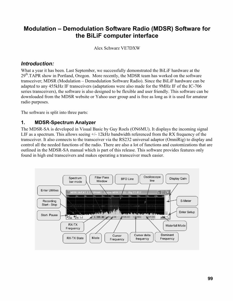
1. MDSR-Spectrum Analyzer The MDSR-SA is developed in Visual Basic by Guy Roels (ON6MU). It displays the incoming signal LIF as a spectrum. This allows seeing +/- 12kHz bandwidth referenced from the RX frequency of the transceiver. It also connects to the transceiver via the RS232 universal adaptor (OmniRig) to display and control all the needed functions of the radio. There are also a lot of functions and customizations that are outlined in the MDSR-SA manual which is part of this release. This software provides features only found in high end transceivers and makes operating a transceiver much easier.
100
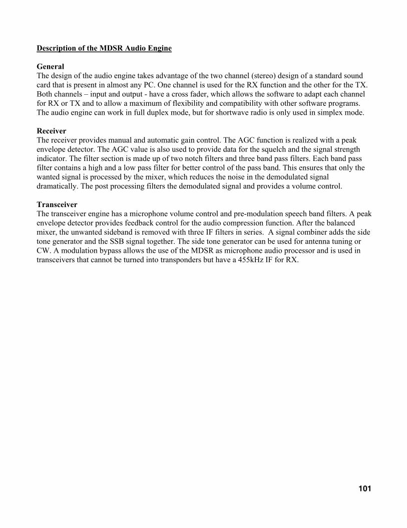
2. OmniRIG – Universal RS232 Interface OmniRig is developed by Alex Shovkoplyas (VE3NEA). It is a universal CAT interface translator and provides 48 different CAT control interfaces. This software was written before the MDSR and was adopted into the MDSR-SA software by ON6MU. VE3NEA gave us permission to use his software and all the CAT control strings for all the different transceivers. This allowed the MDSR team to really develop a universal and versatile software transceiver.
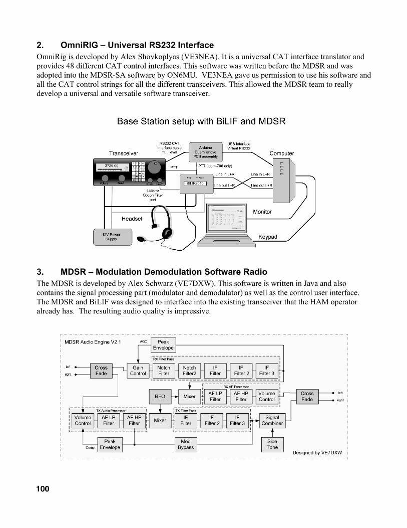
3. MDSR – Modulation Demodulation Software Radio The MDSR is developed by Alex Schwarz (VE7DXW). This software is written in Java and also contains the signal processing part (modulator and demodulator) as well as the control user interface. The MDSR and BiLIF was designed to interface into the existing transceiver that the HAM operator already has. The resulting audio quality is impressive.
101
Description of the MDSR Audio Engine General The design of the audio engine takes advantage of the two channel (stereo) design of a standard sound card that is present in almost any PC. One channel is used for the RX function and the other for the TX. Both channels – input and output - have a cross fader, which allows the software to adapt each channel for RX or TX and to allow a maximum of flexibility and compatibility with other software programs. The audio engine can work in full duplex mode, but for shortwave radio is only used in simplex mode. Receiver The receiver provides manual and automatic gain control. The AGC function is realized with a peak envelope detector. The AGC value is also used to provide data for the squelch and the signal strength indicator. The filter section is made up of two notch filters and three band pass filters. Each band pass filter contains a high and a low pass filter for better control of the pass band. This ensures that only the wanted signal is processed by the mixer, which reduces the noise in the demodulated signal dramatically. The post processing filters the demodulated signal and provides a volume control. Transceiver The transceiver engine has a microphone volume control and pre-modulation speech band filters. A peakenvelope detector provides feedback control for the audio compression function. After the balanced mixer, the unwanted sideband is removed with three IF filters in series. A signal combiner adds the side tone generator and the SSB signal together. The side tone generator can be used for antenna tuning or CW. A modulation bypass allows the use of the MDSR as microphone audio processor and is used in transceivers that cannot be turned into transponders but have a 455kHz IF for RX.
102
MDSR V2.1J Manual Intro: This software was written by Alex Schwarz (VE7DXW) to produce a very clean modulator and de-modulator for USB, LSB and CW for use in the shortwave bands. The spectrum analyzer that works in conjunction with this software is the MDSR-SA designed by Guy Roels (ON6MU). The CAT interface (OmniRig) is provided by Alex Shovkoplyas (VE3NEA) and implemented by Guy into the MDSR-SA . This de-modulator is designed to work with a single-ended 12kHz IF signal provided to the mic or line input of a soundcard. Unlike all other SDR software, this program will work with the LIF2010 PCB or both single-ended down-converters described on the website http://users.skynet.be/myspace/mdsr. The advantage of using an existing transceiver is that today’s commercial amateur radios are very rugged and they also have a very good IP3 intercept point. All the other low priced SDR hardware is very prone to cross-modulation in strong signal conditions. Now, with the additional modulator, the MDSR software can upgrade older shortwave transceivers to the latest SDR interface with all the DSP features only found in high end units. The BiLIF interface takes advantage of the sturdiness of commercial radios and the MDSR provides the graphic user interface and signal processing. An existing radio can be upgraded and enhanced without a lot of expense.
Changes and updates in the MDSR software release Summary: The MDSR Team has been hard at work developing the next step of the DADP. The MDSR synthesizer provides a full RX – TX capable DSP engine and utilizes the soundcard to convert the digital audio stream into an analog 12kHz IF output. The MDSR-SA is the companion software and was derived from the DADP-SA. The development of the original CAT interface was discontinued and, instead, the OmniRig CAT interface was implemented for greater functionality and compatibility with 48 transceivers. The MDSR software adds the following features to the DADP MDSR: a fully RX – TX capable USB, LSB, CW synthesizer engine with user interface
Synthesized TX modulator SSB modulation can be turned off to allow for post modulation processing only Audio synthesizer and voice compressor Synthesized carrier for easy antenna tuning Normal or reversed USB – LSB filter function Frequency calibrator which allows for a wide range of LO frequencies A wide range of selectable BFO frequencies ( 9kHz to 18kHz) Additional auto notch filter for better beat suppression User interface supporting multiple independent graphic windows
MDSR-SA: spectrum analyzer and function display
Highlighted filter band Multi function display Spectral line or bar function Waterfall mode Audio recording and playback function
103
OmniRig: CAT support for multiple transceivers Support of 48 preconfigured transceivers Easy setup using the OmniRig interface Second PTT COM port for support of transceivers without CAT PTT command PTT set through RTS-DTR or Arduino PCB with special C routine (avail. from the group)
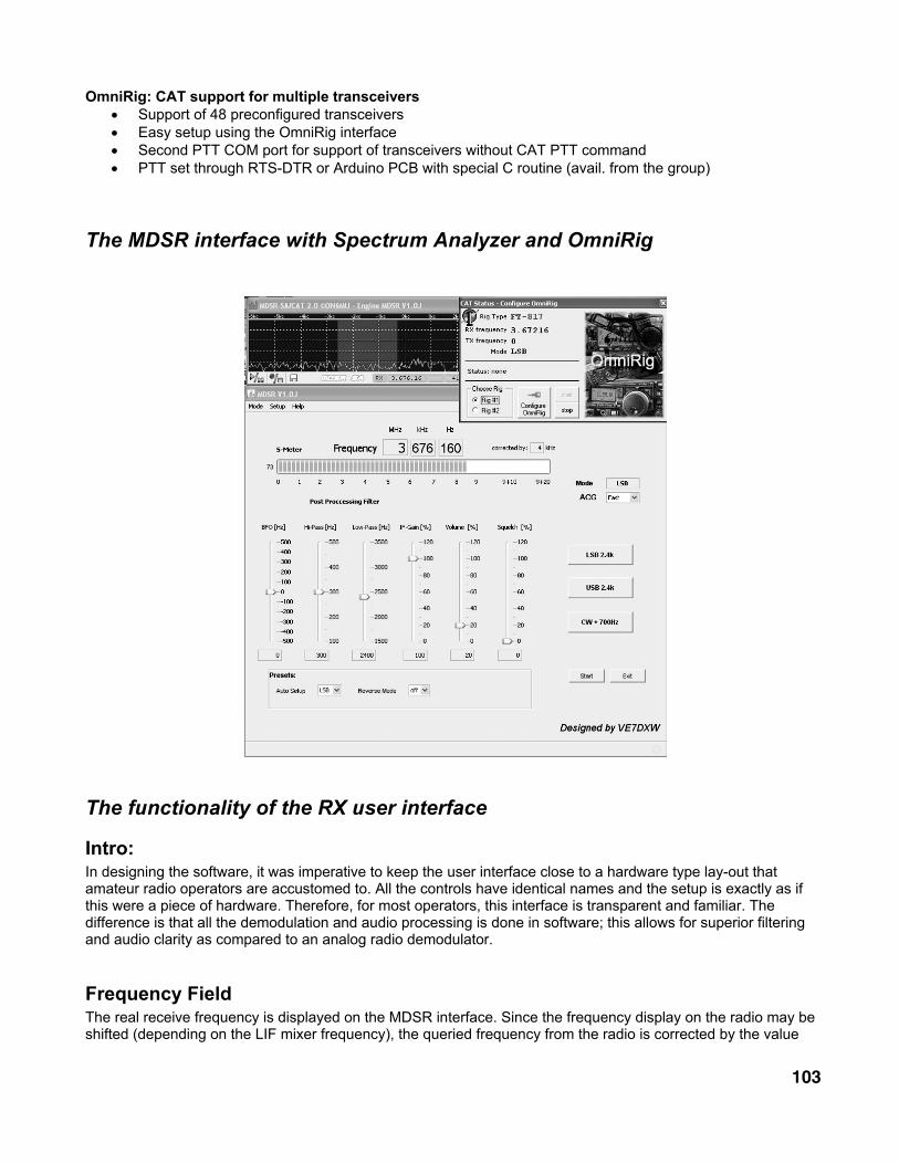
The MDSR interface with Spectrum Analyzer and OmniRig
The functionality of the RX user interface
Intro: In designing the software, it was imperative to keep the user interface close to a hardware type lay-out that amateur radio operators are accustomed to. All the controls have identical names and the setup is exactly as if this were a piece of hardware. Therefore, for most operators, this interface is transparent and familiar. The difference is that all the demodulation and audio processing is done in software; this allows for superior filtering and audio clarity as compared to an analog radio demodulator.
Frequency Field The real receive frequency is displayed on the MDSR interface. Since the frequency display on the radio may be shifted (depending on the LIF mixer frequency), the queried frequency from the radio is corrected by the value
104
specified in the calibration window. For instructions on how to set up the correct RX frequency display, refer to the calibration procedure in this document.
IF Frequency Field The IF Frequency field shows the currently selected BFO frequency. The BFO frequency can change depending on the mode the MDSR is set to. This is done in the Setup – Calibration window. See also: “Lock to TXVR” mode and presets.
Corrected by Field The “Corrected by” field shows the value of the frequency in kHz steps that is added to the frequency display in the computer. This matches the real RX – TX frequency of the MDSR in case the BFO adjustment can not completely remove any offset. This setup is done in the Setup – Calibration window.
Signal Strength Indicator (S-Meter) The bar graph in the MDSR window indicates the signal level of the incoming 12kHz audio, similar to an audio level meter. The difference is that the units are in s increments. The input audio needs to be adjusted to match thereal S-meter readings of the receiver.
BFO Control The BFO control shifts the 12kHz BFO frequency in increments of 1Hz to + or – 500Hz offset. With newer radios that have a resolution of 10Hz, this control will not be needed. But when using a shortwave receiver with a 1kHz or 100Hz resolution, this control will help to synchronize the BFO with the incoming SSB signal to get the best audio clarity.
Post Processing Filters The post processing filters filter the audio after it has been demodulated. This will provide extra noise reduction onweak signals. In its default setting, it provides a 300 to 2400Hz audio pass.
Hi Pass: The Hi Pass control is set to 300Hz cutoff frequency by default. When a strong signal is received, it can be set to 100Hz to provide better audio fidelity. In cases of poor reception, the filter can be moved up. This will reduce noise but will also reduce readability if it is moved up too far. Low Pass: The Low Pass control is set to 2400Hz cutoff by default. Under normal conditions, this setting provides the best readability of the received audio. To get better fidelity of a strong signal, the control can be moved higher but doing so will also increase hiss. In cases of poor reception, the control can be moved down to narrow the audio pass which will reduce hiss. If it is moved too far, the audio will become unintelligible.
IF Gain The IF Gain controls the level of the 12kHz IF (LIF) before it is sent to the digital IF filters. Its default setting is 100%. When AGC is enabled, this control should be left at 100%. Changing the IF Gain with the AGC enabled will have a limited effect because the AGC will try to compensate for the different setting. With the AGC off, the IF Gain should be set to best audio quality. Note: since the volume of demodulated SSB signal changes with the signal strength, the change in volume (without AGC) can be uncomfortable especially when using earphones.
Volume The volume control sets the volume of the received signal after the demodulation and it does not affect the AGC control as the IF Gain does.
Squelch The Squelch control enables the quieting of the output at a specified signal level. It is not usually used while receiving SSB or CW. It has been included in the software in case an FM demodulator is added to the software package at a later date.
105
AGC Control The AGC system equalizes the output volume and increases the S/N ratio on strong signals. Because different noise levels and noise types require different AGC speeds, four different settings have been implemented. To get the best audio performance, the user will select the speed that best stabilizes the S-meter display. If the audio volume is pumping, a slower speed should be selected. If the volume is too dynamic, a faster speed should be selected. On very low signals it might be necessary to turn the AGC off to get the best performance.
Fast: decay time 1s Medium: decay time 1.4s Slow: decay time 1.8s Off: decay time 1s (no AGC control) Off Scale: decay time 0.1s (for fast recovery after static crashes)
The MDSR ACG level is indicated with the S-meter bar graph.
Mode Currently there are 3 different demodulation types available on the MDSR software. USB, LSB and CW + 700Hz (essentially USB with a narrow IF filter optimized for CW signals offset + 700Hz from the carrier)
LSB bw = 1.8, 2.4 3.2kHz USB bw =1.8, 2.4 3.2kHz CW bw = 0.8kHz
Presets Auto Setup: instructs the CAT software to set the radio into the transponder demodulation mode
automatically. If the auto setup is selected to “Lock to TXVR” the MDSR and the transceiver’s mode will be locked. See also: “Calibration” for more details.
Reverse Mode: if the LO is below the IF frequency, as in the case of the 9MHz LO for the ICOM-706
transceiver, USB and LSB flip. Setting this to “on” will provide the correct button labels by reversing their functions.
Start When the program starts, the synthesis engine does not start automatically unless it is set up in the MDSR-SA automation properties which define which programs (auto-start and close for MDSR and OmniCAT) will be launched and started on startup. This will allow all programs related to the MDSR to work in unison. The start button starts the synthesis engine. On startup, the filters of the synthesis engine will run the last set properties that were stored in a configuration file before the software was closed.
Exit The exit button closes the program and turns off the synthesis engine. This button should always be used to exit the program rather than merely closing the window.
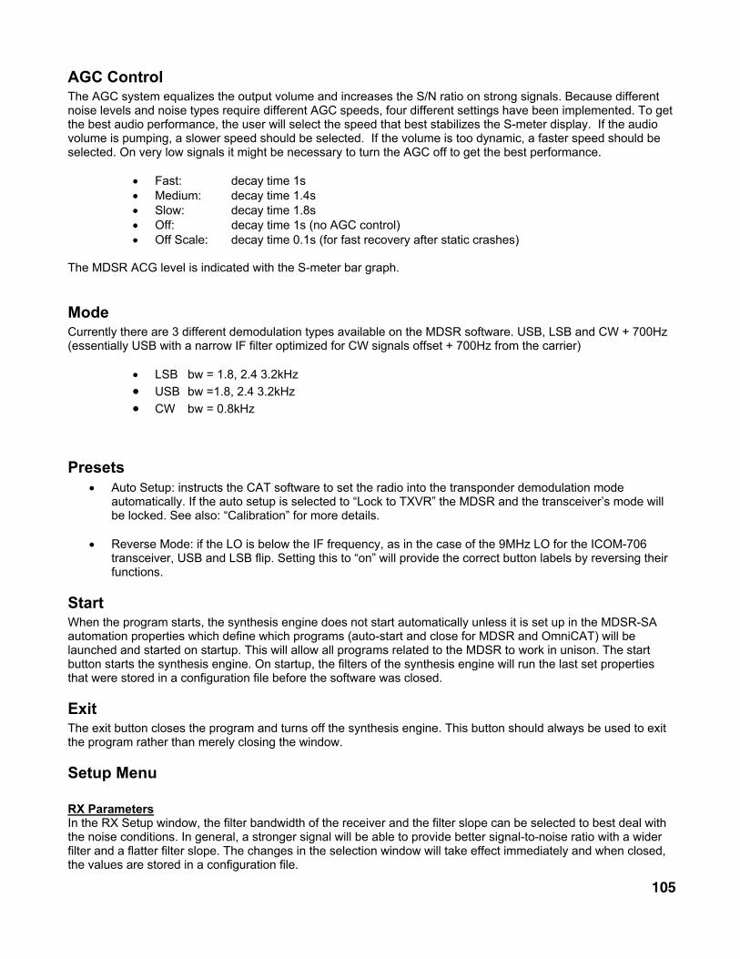
Setup Menu RX Parameters In the RX Setup window, the filter bandwidth of the receiver and the filter slope can be selected to best deal with the noise conditions. In general, a stronger signal will be able to provide better signal-to-noise ratio with a wider filter and a flatter filter slope. The changes in the selection window will take effect immediately and when closed, the values are stored in a configuration file.
106
This panel operates and moves independently from the main RX window. Note: the RX and TX filter settings in this software release are the same.
The following filter settings are available:
CW: 800Hz – Slope: steep – medium – flat Narrow: 1.8kHz – Slope: steep – medium – flat Medium:2.4kHz – Slope: steep – medium – flat Wide: 3.2kHz – Slope: steep – medium – flat
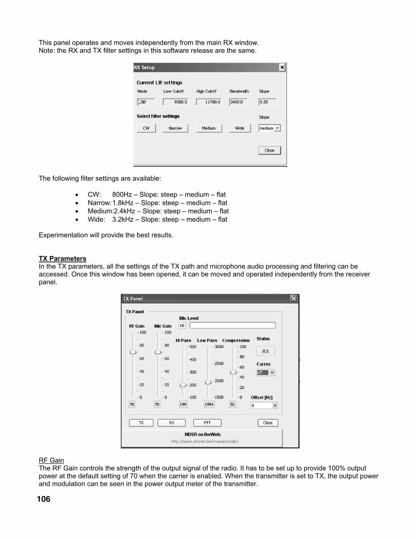
Experimentation will provide the best results. TX Parameters In the TX parameters, all the settings of the TX path and microphone audio processing and filtering can be accessed. Once this window has been opened, it can be moved and operated independently from the receiver panel.
RF Gain The RF Gain controls the strength of the output signal of the radio. It has to be set up to provide 100% output power at the default setting of 70 when the carrier is enabled. When the transmitter is set to TX, the output power and modulation can be seen in the power output meter of the transmitter.
107
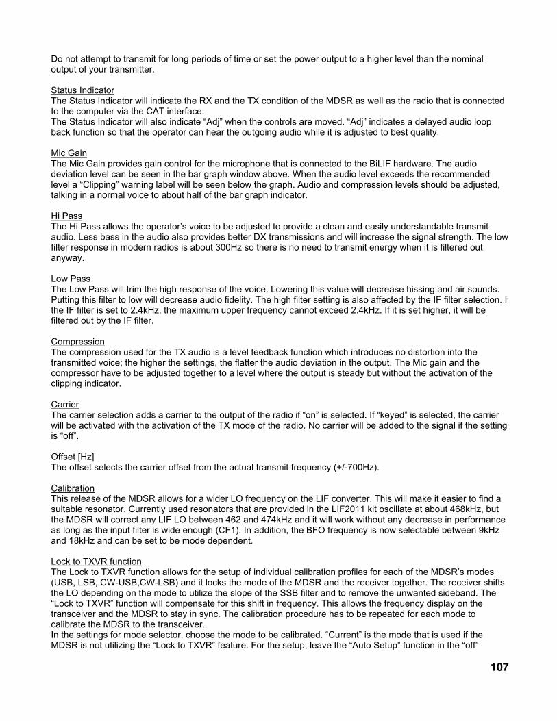
Do not attempt to transmit for long periods of time or set the power output to a higher level than the nominal output of your transmitter. Status Indicator The Status Indicator will indicate the RX and the TX condition of the MDSR as well as the radio that is connected to the computer via the CAT interface. The Status Indicator will also indicate “Adj” when the controls are moved. “Adj” indicates a delayed audio loop back function so that the operator can hear the outgoing audio while it is adjusted to best quality. Mic Gain The Mic Gain provides gain control for the microphone that is connected to the BiLIF hardware. The audio deviation level can be seen in the bar graph window above. When the audio level exceeds the recommended level a “Clipping” warning label will be seen below the graph. Audio and compression levels should be adjusted, talking in a normal voice to about half of the bar graph indicator. Hi Pass The Hi Pass allows the operator’s voice to be adjusted to provide a clean and easily understandable transmit audio. Less bass in the audio also provides better DX transmissions and will increase the signal strength. The low filter response in modern radios is about 300Hz so there is no need to transmit energy when it is filtered out anyway. Low Pass The Low Pass will trim the high response of the voice. Lowering this value will decrease hissing and air sounds. Putting this filter to low will decrease audio fidelity. The high filter setting is also affected by the IF filter selection. Ifthe IF filter is set to 2.4kHz, the maximum upper frequency cannot exceed 2.4kHz. If it is set higher, it will be filtered out by the IF filter. Compression The compression used for the TX audio is a level feedback function which introduces no distortion into the transmitted voice; the higher the settings, the flatter the audio deviation in the output. The Mic gain and the compressor have to be adjusted together to a level where the output is steady but without the activation of the clipping indicator. Carrier The carrier selection adds a carrier to the output of the radio if “on” is selected. If “keyed” is selected, the carrier will be activated with the activation of the TX mode of the radio. No carrier will be added to the signal if the setting is “off”. Offset [Hz] The offset selects the carrier offset from the actual transmit frequency (+/-700Hz). Calibration This release of the MDSR allows for a wider LO frequency on the LIF converter. This will make it easier to find a suitable resonator. Currently used resonators that are provided in the LIF2011 kit oscillate at about 468kHz, but the MDSR will correct any LIF LO between 462 and 474kHz and it will work without any decrease in performance as long as the input filter is wide enough (CF1). In addition, the BFO frequency is now selectable between 9kHz and 18kHz and can be set to be mode dependent. Lock to TXVR function The Lock to TXVR function allows for the setup of individual calibration profiles for each of the MDSR’s modes (USB, LSB, CW-USB,CW-LSB) and it locks the mode of the MDSR and the receiver together. The receiver shifts the LO depending on the mode to utilize the slope of the SSB filter and to remove the unwanted sideband. The “Lock to TXVR” function will compensate for this shift in frequency. This allows the frequency display on the transceiver and the MDSR to stay in sync. The calibration procedure has to be repeated for each mode to calibrate the MDSR to the transceiver. In the settings for mode selector, choose the mode to be calibrated. “Current” is the mode that is used if the MDSR is not utilizing the “Lock to TXVR” feature. For the setup, leave the “Auto Setup” function in the “off”
108
position and manually change the mode of the transceiver. For each available mode, this setup has to be repeated. The CW mode is in essential SSB with a 700Hz offset for the CW side tone generation.
Calibration Procedure
1. Measure the LO frequency of the LIF2011 with a high impedance frequency counter 2. Set the receiver to 10.000.00MHz. The peak of WWV should be seen in the spectrum. 3. Only for “current mode” setup: Select the mode USB or LSB that causes the least amount of offset
from the center frequency. 4. Select the IF frequency (9 – 18kHz) that closest matches your LIF frequency (LIF=LO-IF) 5. With the slide control, adjust the offset frequency to the nearest kHz marker on the spectrum analyzer.
Steps 6 and 7 are not necessary if the LO is in between 464 and 473kHz 6. Tune the radio until the WWV peak is exactly in the center of the spectrum analyzer. The offset of the
radio should be precise in kHz steps. 7. With the “Correction Frequency Selector” add or subtract digits until the displayed frequency in the MDSR
display matches the real receiving frequency. The radio display will not be corrected and should not be used as reference.
8. Click on the “save” button to save the setup before going on to the next mode.
The settings of these parameters are stored on the hard drive and are automatically loaded when the MDSR engine is launched. For example: Set the receiver to 10.000.00MHz. If the LO frequency is 462.758kHz the signal peak will be off by 3.758kHz in LSB and 6.758kHz in USB mode. In this case, LSB is selected because it causes the least amount of offset. This mode has to be selected anytime the MDSR is used to demodulate otherwise the displayed frequency will not match. With the slide control, subtract 242Hz from the BFO which places the peak of the WWV exactly 4kHz above center. Now tune the radio to 9.996kHz and the peak will be exactly in the center of the spectrum. In order to match the real RX frequency, 4kHz have to be added to the display by selecting 4kHz in the Correction Frequency Selector. The displayed frequency in the MDSR is now corrected to 10.000.00MHz. Audio Setting In Audio Settings, the audio card input and output can be assigned (reversed). This provides more flexibility on setting up the LIF converter interface. If the input signal is low, a +20dB boost can be selected. Also the function of the microphone audio processing can be selected. In the case that the transceiver’s internal modulation is used, the DSP modulation can be turned off.
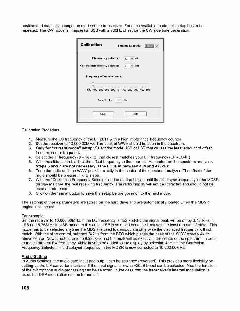
109
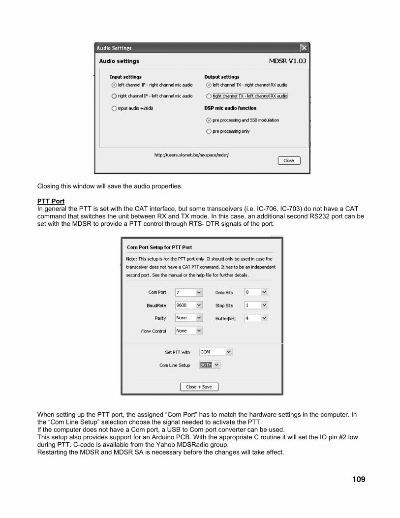
Closing this window will save the audio properties. PTT Port In general the PTT is set with the CAT interface, but some transceivers (i.e. IC-706, IC-703) do not have a CAT command that switches the unit between RX and TX mode. In this case, an additional second RS232 port can be set with the MDSR to provide a PTT control through RTS- DTR signals of the port.
When setting up the PTT port, the assigned “Com Port” has to match the hardware settings in the computer. In the “Com Line Setup” selection choose the signal needed to activate the PTT. If the computer does not have a Com port, a USB to Com port converter can be used. This setup also provides support for an Arduino PCB. With the appropriate C routine it will set the IO pin #2 low during PTT. C-code is available from the Yahoo MDSRadio group. Restarting the MDSR and MDSR SA is necessary before the changes will take effect.
110
How to install the MDSR on a Windows Computer
Intro The MDSR software will work with almost any full duplex sound card. The prototype software was developed on a 24bit SoundBlaster audio card and some limited testing has been done on lower quality 16bit onboard audio devices with excellent results.
Use the following installation program and follow instructions. MDSR-Win32-Setup.exe At the end of the installation program, the Java run time environment has to be installed if it is not already present on the computer. The installation program automates this process. The file can be obtained from the MDSRadio Yahoo Group in the files section.
How to set the audio properties on a Windows Computer
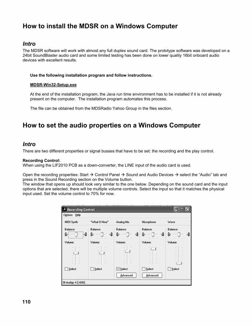
Intro There are two different properties or signal busses that have to be set: the recording and the play control. Recording Control: When using the LIF2010 PCB as a down-converter, the LINE input of the audio card is used. Open the recording properties: Start Control Panel Sound and Audio Devices select the “Audio” tab and press in the Sound Recording section on the Volume button. The window that opens up should look very similar to the one below. Depending on the sound card and the input options that are selected, there will be multiple volume controls. Select the input so that it matches the physical input used. Set the volume control to 70% for now.
111
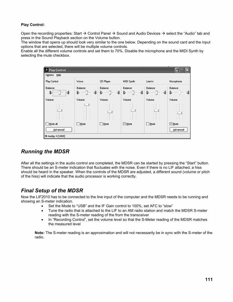
Play Control: Open the recording properties: Start Control Panel Sound and Audio Devices select the “Audio” tab and press in the Sound Playback section on the Volume button. The window that opens up should look very similar to the one below. Depending on the sound card and the input options that are selected, there will be multiple volume controls. Enable all the different volume controls and set them to 70%. Disable the microphone and the MIDI Synth by selecting the mute checkbox.
Running the MDSR After all the settings in the audio control are completed, the MDSR can be started by pressing the “Start” button. There should be an S-meter indication that fluctuates with the noise. Even if there is no LIF attached, a hiss should be heard in the speaker. When the controls of the MDSR are adjusted, a different sound (volume or pitch of the hiss) will indicate that the audio processor is working correctly.
Final Setup of the MDSR Now the LIF2010 has to be connected to the line input of the computer and the MDSR needs to be running and showing an S-meter indication.
Set the Mode to “USB” and the IF Gain control to 100%, set AFC to “slow” Tune the radio that is attached to the LIF to an AM radio station and match the MDSR S-meter
reading with the S-meter reading of the from the transceiver In “Recording Control”, set the volume level so that the S-Meter reading of the MDSR matches
the measured level
Note: The S-meter reading is an approximation and will not necessarily be in sync with the S-meter of the radio.
112
MDSR V1.1J -- MDSR-SA 2.0 – OmniRig
Intro: The MDSR-SA spectrum analyzer has been designed by Guy Roels (ON6MU) primarily for use with the MDSR-J modulator – demodulator application designed by Alex Schwarz (VE7DXW). It uses OmniRig to communicate with the transceiver and MDSR-engine. OmniRig is a universal CAT interface and can communicate with 48 different makes and models of transceivers. OmniRig was designed by Alex Shovkoplyas (VE3NEA). This software package integrates the computer with the HF transceiver and creates a sophisticated and easy to use interface and it provides functionality otherwise only found in high end transceivers. This de-modulator is designed to work with a single-ended 12kHz IF signal provided to the mic or line input of a soundcard. Unlike all other SDR software, this program will work with the LIF2010 PCB or both single-ended down-converters described on the website http://users.skynet.be/myspace/mdsr. The advantage of using an existing transceiver is that today’s commercial amateur radios are very rugged and they also have a very good IP3 intercept point. All the other low priced SDR hardware is very prone to cross-modulation in strong signal conditions. Now, with the additional modulator, the MDSR software can upgrade older shortwave transceivers to the latest SDR interface with all the DSP features only found in high end units. The BiLIF interface takes advantage of the sturdiness of commercial radios and the MDSR provides the graphic user interface and signal processing. An existing radio can be upgraded and enhanced without a lot of expense.
Changes and updates in the MDSR-SA software release Summary: The MDSR Team has been hard at work developing the next step of the DADP. The MDSR synthesizer provides a full RX – TX capable DSP engine and utilizes the soundcard to convert the digital audio stream into an analog 12kHz IF output. The MDSR-SA is the companion software and was derived from the DADP-SA. The development of the original CAT interface was discontinued and, instead, the OmniRig CAT interface was implemented for greater functionality and compatibility with 48 transceivers. The MDSR software offers the following features MDSR-SA: spectrum analyzer and function display
Spectrum analysis Basic oscilloscope Highlighted filter band Multi function display (delta frequency, dominant frequency, RX frequency, mode, RX-TX) Spectral line or bar function Waterfall mode Audio recording and playback function Favorite frequency short cuts and auto update of the transceiver A fast variety of customization utilities (colors, bar or line display, resolution, zoom, average time and
more...) Graphic capture of spectrum window Rate of integration with the MDSR is customizable via menu setup
113
MDSR: a fully RX – TX capable USB, LSB, CW synthesizer engine with user interface Synthesized TX modulator SSB modulation can be turned off to allow for post modulation processing only Audio synthesizer and voice compressor Synthesized carrier for easy antenna tuning Normal or reversed USB – LSB filter function Lock to TXCR – a feature that allows the synchronization of the mode to the transceiver with the MDSR’s
mode Frequency calibrator which allows for a wide range of LO frequencies A wide range of selectable BFO frequencies ( 9kHz to 18kHz) Additional auto notch filter for better beat suppression User interface supporting multiple independent graphic windows
OmniRig: CAT support for multiple transceivers
Support of 48 preconfigured transceivers Easy setup using the OmniRig interface Second PTT COM port for support of transceivers without CAT PTT command PTT set through RTS-DTR or Arduino PCB with special C routine (avail. from the group)
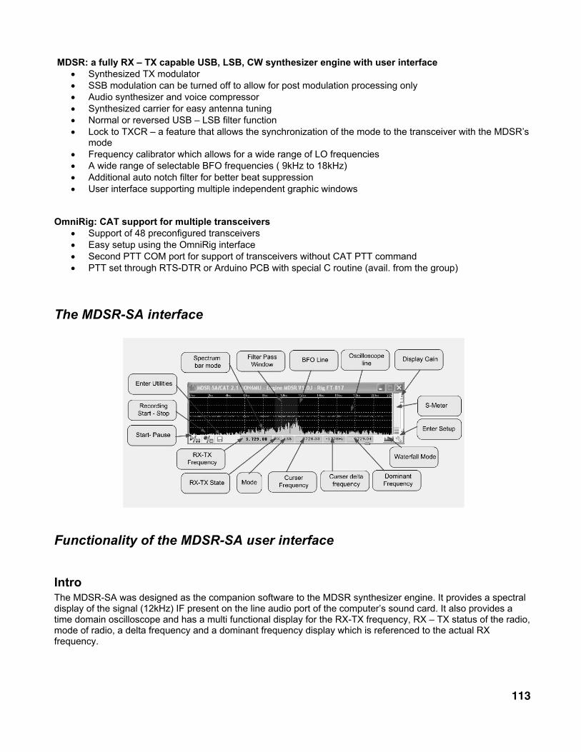
The MDSR-SA interface
Functionality of the MDSR-SA user interface
Intro The MDSR-SA was designed as the companion software to the MDSR synthesizer engine. It provides a spectral display of the signal (12kHz) IF present on the line audio port of the computer’s sound card. It also provides a time domain oscilloscope and has a multi functional display for the RX-TX frequency, RX – TX status of the radio, mode of radio, a delta frequency and a dominant frequency display which is referenced to the actual RX frequency.
114
FUNCTIONS
Spectrum Analysis In the spectrum analysis window the resulting spectrum of the input signal (either line input or microphone input) of the sound card is displayed. The spectrum display can be customized to provide the best viewing results for the user. For the best resolution, the recording sample rate has to be set to the highest possible setting. MDSR-SA Settings
Spectrum Mode: either normal – no filter window (0kc – 22kc display range) Full Spectrum – BFO line and filter window (0kc – 22kc range) Zoomed Spectrum - BFO line and filter window (+/- 3kc range)
Stay on Top: this selection keeps the SA application on top of all other apps. Spectrum Bars: switches spectral display from line mode to bar mode Oscilloscope: turns the oscilloscope on or off Remember Screen Size: keeps the current size of the window even if application is exited and
then restarted Absolute Screen Labels: displays the actual frequency as received in the soundcard; relative is
referenced from the BFO line Dominant Frequency Detection: measures and displays the frequency of the highest peak in the
spectrum. If unchecked this field will not be visible in the multifunctional toolbar. Edit User Colors: allows for customization of the spectral display window.
In the Calibrate and Customize menu the Scan Frequency timing which affects the rise and fall time of the spectrum can be selected. The Spectrum and Base sensitivity affects the size and the noise floor line of the spectrum. Values from 1 – 99 are acceptable, 99 is the most sensitive setting.
Basic Oscilloscope The Basic Oscilloscope measures and displays the V/t domain present on the line or microphone input of the soundcard. This measurement can be turned off via the menu function. In the Calibrate and Customize menu the Oscilloscope sensitivity values are 1 to 20, 20 being most sensitive.
Waterfall The Waterfall is a different way of displaying the spectrum with the advantage of having a time segment of the spectrum displayed. In a normal spectrum display, the y axis is the intensity of the signal; in a waterfall display, the y axis is a time domain. The intensity of the signal is displayed in the variance of the gray or color scale. The latest spectral line is added on the top and the lines are moved down. This creates a waterfall effect. This type of display can be used to decode CW or display digital modulation schemes like PSK.
In the Calibrate and Customize menu, the Waterfall Clarity can be adjusted between 0 – 99. The base color can be selected in either one of the basic colors (red, green, blue), grayscale or color variance. The waterfall speed can be set between 1–10.
Dominant frequency detection The dominant frequency detection indicates the most prominent (strongest) spectral line and displays its frequency corrected to the actual incoming RF signal. This field can be turned off if it is not needed. Left clicking on the displayed value will set the transceiver to the currently displayed value. This can be used to set the radio to a peak without using the frequency dial of the radio.
115
Easy one-button start/pause The FFT (Fast Fourier Transformation) that changes the signal from time domain to frequency domain is very processor intensive. If the computer is being used for a different task and the processor time is needed, the spectrum analyzer can be paused. The SA window will freeze and the processor can perform other tasks. If the processor speed of the computer has trouble with the FFT process, fewer spectral lines can be selected in the Calibration and Customization setup. By selecting a lower resolution, less processor time is needed and the MDSR program can coexist with other software programs.
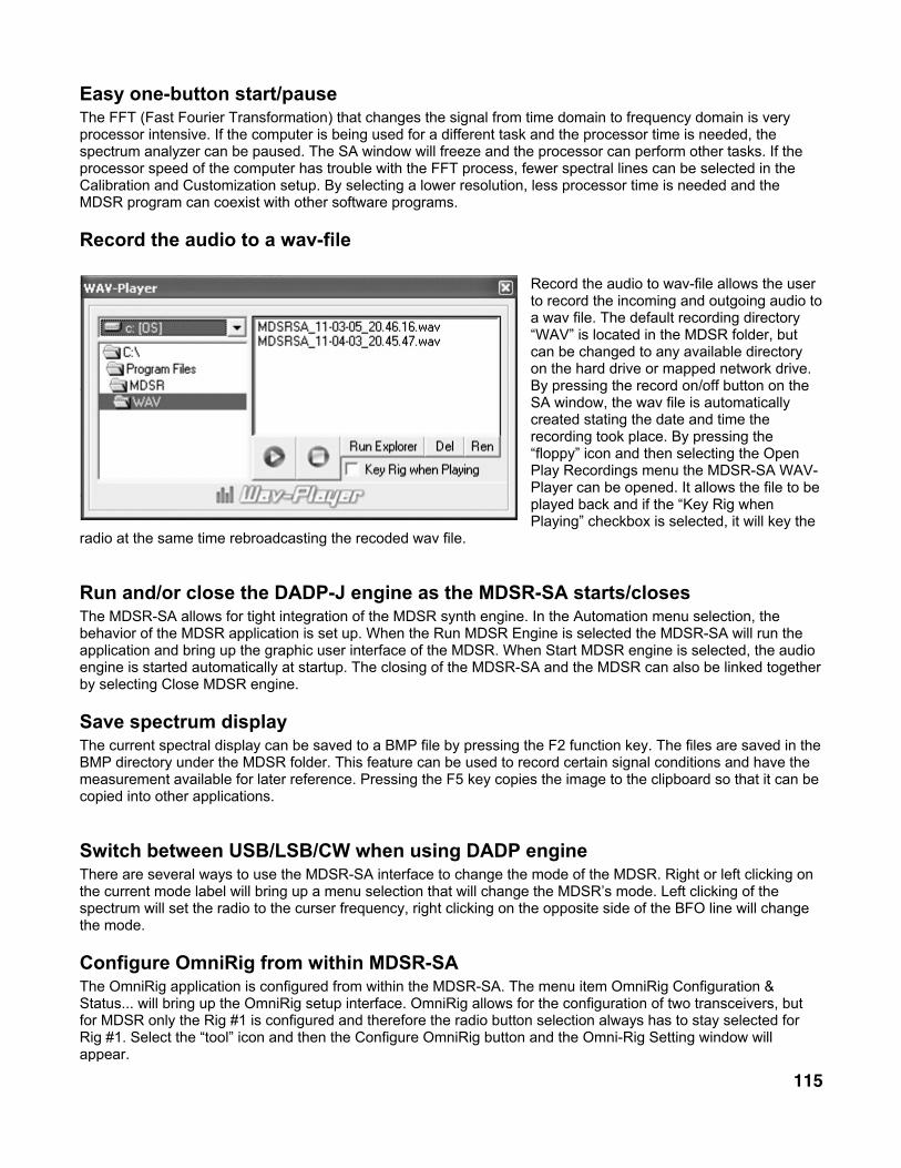
Record the audio to a wav-file
Record the audio to wav-file allows the user to record the incoming and outgoing audio to a wav file. The default recording directory “WAV” is located in the MDSR folder, but can be changed to any available directory on the hard drive or mapped network drive. By pressing the record on/off button on the SA window, the wav file is automatically created stating the date and time the recording took place. By pressing the “floppy” icon and then selecting the Open Play Recordings menu the MDSR-SA WAV-Player can be opened. It allows the file to be played back and if the “Key Rig when Playing” checkbox is selected, it will key the
radio at the same time rebroadcasting the recoded wav file.
Run and/or close the DADP-J engine as the MDSR-SA starts/closes The MDSR-SA allows for tight integration of the MDSR synth engine. In the Automation menu selection, the behavior of the MDSR application is set up. When the Run MDSR Engine is selected the MDSR-SA will run the application and bring up the graphic user interface of the MDSR. When Start MDSR engine is selected, the audio engine is started automatically at startup. The closing of the MDSR-SA and the MDSR can also be linked together by selecting Close MDSR engine.
Save spectrum display The current spectral display can be saved to a BMP file by pressing the F2 function key. The files are saved in the BMP directory under the MDSR folder. This feature can be used to record certain signal conditions and have the measurement available for later reference. Pressing the F5 key copies the image to the clipboard so that it can be copied into other applications.
Switch between USB/LSB/CW when using DADP engine There are several ways to use the MDSR-SA interface to change the mode of the MDSR. Right or left clicking on the current mode label will bring up a menu selection that will change the MDSR’s mode. Left clicking of the spectrum will set the radio to the curser frequency, right clicking on the opposite side of the BFO line will change the mode.
Configure OmniRig from within MDSR-SA The OmniRig application is configured from within the MDSR-SA. The menu item OmniRig Configuration & Status... will bring up the OmniRig setup interface. OmniRig allows for the configuration of two transceivers, but for MDSR only the Rig #1 is configured and therefore the radio button selection always has to stay selected for Rig #1. Select the “tool” icon and then the Configure OmniRig button and the Omni-Rig Setting window will appear.
116
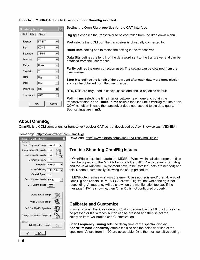
Important: MDSR-SA does NOT work without OmniRig installed.
Setting the OmniRig properties for the CAT interface Rig type chooses the transceiver to be controlled from the drop down menu. Port selects the COM port the transceiver is physically connected to. Baud Rate setting has to match the setting in the transceiver. Data Bits defines the length of the data word sent to the transceiver and can be obtained from the user manual. Parity defines the error correction used. The setting can be obtained from the user manual. Stop bits defines the length of the data sent after each data word transmission and can be obtained from the user manual. RTS, DTR are only used in special cases and should be left as default. Poll int, ms selects the time interval between each query to obtain the transceiver status and Timeout, ms selects the time until OmniRig returns a “No COM” condition in case the transceiver does not respond to the data query. Both settings are in mS.
About OmniRig OmniRig is a COM component for transceiver/receiver CAT control developed by Alex Shovkoplyas (VE3NEA). Homepage: http://www.dxatlas.com/OmniRig/
Download: http://www.dxatlas.com/OmniRig/Files/OmniRig.zip
Trouble Shooting OmniRig issues If OmniRig is installed outside the MDSR-J Windows installation program, files must be copied into the MDSR-J engine folder (MDSR – by default). OmniRig and the Java Runtime Environment have to be installed (both are needed) and this is done automatically following the setup procedure. If MDSR-SA crashes or shows the error "Class not registered" then download OmniRig and reinstall it. MDSR-SA shows "RigOffLine" when the rig is not responding. A frequency will be shown on the multifunction toolbar. If the message “N/A” is showing, then OmniRig is not configured properly.
Calibrate and Customize In order to open the ‘Calibrate and Customize’ window the F9 function key can be pressed or the ‘wrench’ button can be pressed and then select the selection item ‘Calibration and Customization’. Scan Frequency Timing sets the decay time of the spectral display. Spectrum base Sensitivity affects the size and the noise floor line of the spectrum. Values from 1 – 99 are acceptable, 99 is the most sensitive setting.
117
Oscilloscope Sensitivity affects the size (y axis) of the displayed image; values are 1 to 20, 20 being most sensitive. S-Meter Sensitivity allows calibrating the S-meter bar graph on the right side of the MDSR-window. Acceptable values are between 0.1 to 49; 49 being most sensitive. Resolution sets the base resolution of the spectral display. The resolution can be lowered if there is an issue with performance. Waterfall Clarity can be adjusted between 0 – 99. Waterfall Speed set property between 1 – 10. Recording sample rate should be left at 44100. User Color Settings opens up the color selection window. Place the mouse over the graphics to change the color of the specific items. Audio Input Settings opens up the Windows record control settings. Audio Output Settings opens up the Windows play control settings. CAT OmniRig Configuration opens up the OmniRig configuration window. Change User defined frequency opens up the user defined frequencies window. Total Rest to Defaults resets all the custom settings of the MDSR-SA to the setup default values (use with care).
Set your rig to any band Clicking on the “wrench” icon and selecting ‘Set TRX frequency’ and then selecting the band listing will set the transceiver via the CAT interface to the frequencies defined in the ‘Pre-defined Frequencies and Labels’ setup window.
Set your rig to any frequency Clicking on the “wrench” icon and selecting ‘Set TRX frequency’ and then ‘Enter Frequency’ a frequency can manually be typed in and then by pressing the OK button, the transceiver is updated via the CAT interface.
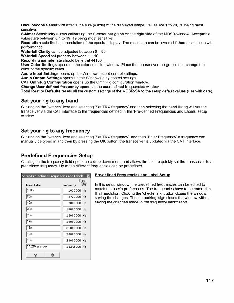
Predefined Frequencies Setup Clicking on the frequency field opens up a drop down menu and allows the user to quickly set the transceiver to a predefined frequency. Up to ten different frequencies can be predefined.
Pre-defined Frequencies and Label Setup In this setup window, the predefined frequencies can be edited to match the user’s preferences. The frequencies have to be entered in [Hz] resolution. Clicking the ‘checkmark’ button closes the window, saving the changes. The ‘no parking’ sign closes the window without saving the changes made to the frequency information.
118
Shortcut Keys MDSR-SA
F2 saves the spectrum display as bmp in the MDSR-SA \BMP folder F5 saves the spectrum display to the clipart F9 calibrates and customizes F11 runs DADP-engine F12 closes DADP engine left-right arrow keys +/-10Hz up-down arrow keys +/- 1Kc PgUp-PgDn keys +/- 1Mc
MDSR [Ctrl] S: starts the MDSR synth engine [Ctrl] U: changes mode to USB [Ctrl] L: changes mode to LSB [Ctrl] W: changes mode to CW-USB [Ctrl] E: exits the MDSR software and closes window [Ctrl] R: opens the filter selection window [Ctrl] T: opens the TX setup window
Mouse Click shortcuts a right-click in spectrum display sets the modulation mode a left-click in spectrum display sets the TRX frequency according to the cursor position in the display
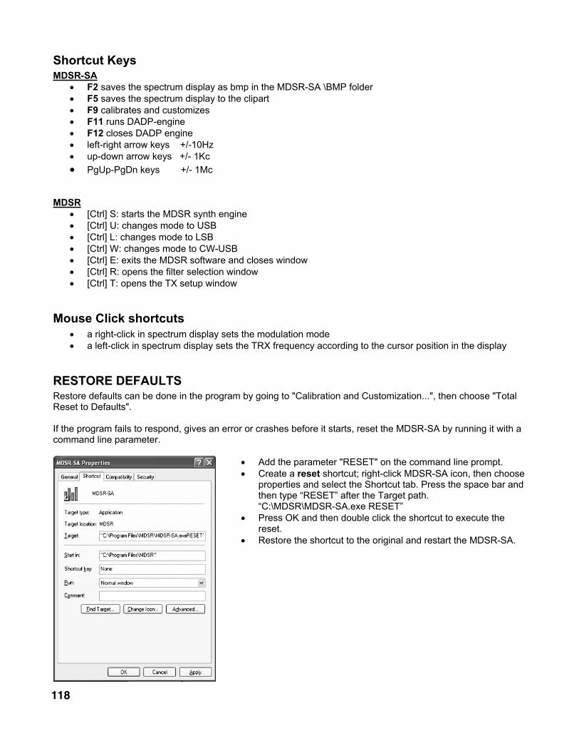
RESTORE DEFAULTS Restore defaults can be done in the program by going to "Calibration and Customization...", then choose "Total Reset to Defaults". If the program fails to respond, gives an error or crashes before it starts, reset the MDSR-SA by running it with a command line parameter.
Add the parameter "RESET" on the command line prompt. Create a reset shortcut; right-click MDSR-SA icon, then choose
properties and select the Shortcut tab. Press the space bar and then type “RESET” after the Target path. “C:\MDSR\MDSR-SA.exe RESET”
Press OK and then double click the shortcut to execute the reset.
Restore the shortcut to the original and restart the MDSR-SA.
119
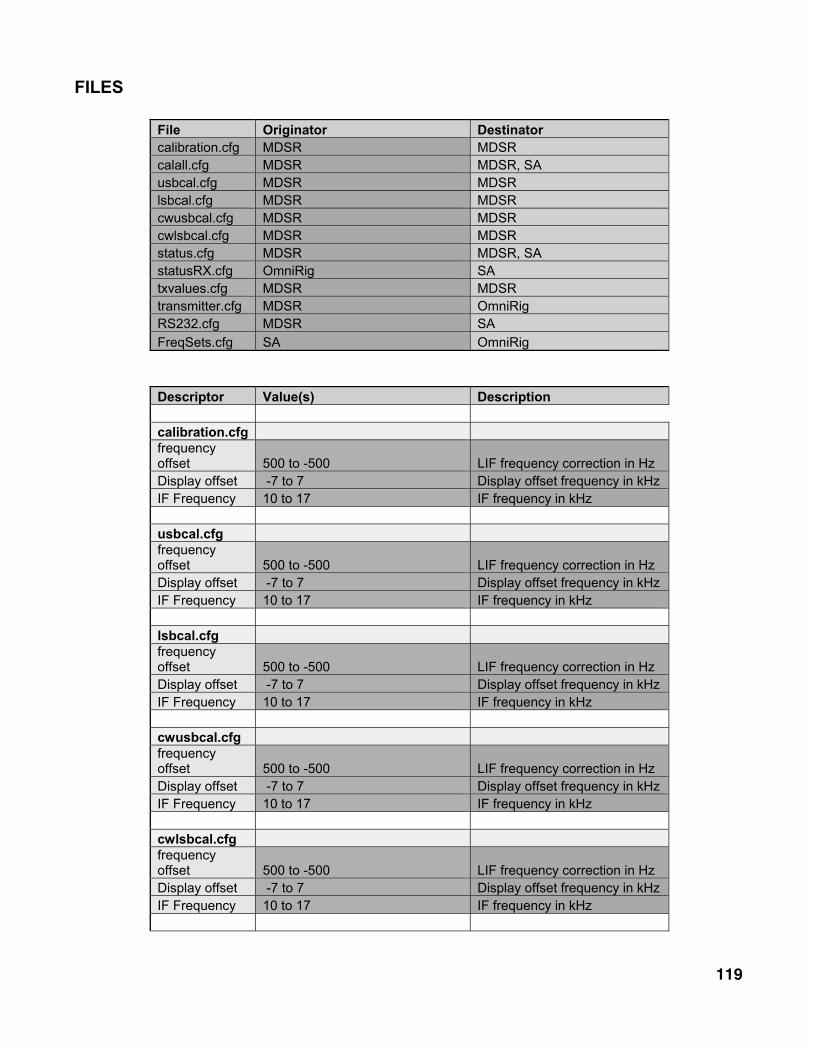
FILES
File Originator Destinator calibration.cfg MDSR MDSR calall.cfg MDSR MDSR, SA usbcal.cfg MDSR MDSR lsbcal.cfg MDSR MDSR cwusbcal.cfg MDSR MDSR cwlsbcal.cfg MDSR MDSR status.cfg MDSR MDSR, SA statusRX.cfg OmniRig SA txvalues.cfg MDSR MDSR transmitter.cfg MDSR OmniRig RS232.cfg MDSR SA FreqSets.cfg SA OmniRig Descriptor Value(s) Description calibration.cfg frequency offset 500 to -500 LIF frequency correction in Hz Display offset -7 to 7 Display offset frequency in kHz IF Frequency 10 to 17 IF frequency in kHz usbcal.cfg frequency offset 500 to -500 LIF frequency correction in Hz Display offset -7 to 7 Display offset frequency in kHz IF Frequency 10 to 17 IF frequency in kHz lsbcal.cfg frequency offset 500 to -500 LIF frequency correction in Hz Display offset -7 to 7 Display offset frequency in kHz IF Frequency 10 to 17 IF frequency in kHz cwusbcal.cfg frequency offset 500 to -500 LIF frequency correction in Hz Display offset -7 to 7 Display offset frequency in kHz IF Frequency 10 to 17 IF frequency in kHz cwlsbcal.cfg frequency offset 500 to -500 LIF frequency correction in Hz Display offset -7 to 7 Display offset frequency in kHz IF Frequency 10 to 17 IF frequency in kHz
120
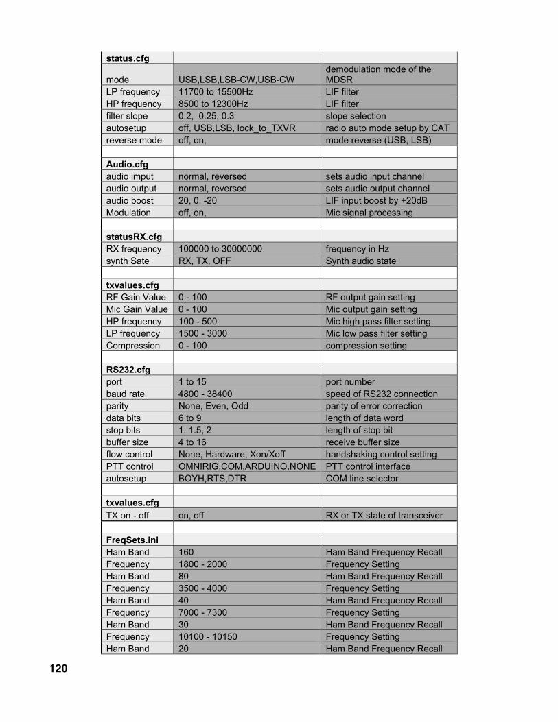
status.cfg
mode USB,LSB,LSB-CW,USB-CW demodulation mode of the MDSR
LP frequency 11700 to 15500Hz LIF filter HP frequency 8500 to 12300Hz LIF filter filter slope 0.2, 0.25, 0.3 slope selection autosetup off, USB,LSB, lock_to_TXVR radio auto mode setup by CAT reverse mode off, on, mode reverse (USB, LSB) Audio.cfg audio imput normal, reversed sets audio input channel audio output normal, reversed sets audio output channel audio boost 20, 0, -20 LIF input boost by +20dB Modulation off, on, Mic signal processing statusRX.cfg RX frequency 100000 to 30000000 frequency in Hz synth Sate RX, TX, OFF Synth audio state txvalues.cfg RF Gain Value 0 - 100 RF output gain setting Mic Gain Value 0 - 100 Mic output gain setting HP frequency 100 - 500 Mic high pass filter setting LP frequency 1500 - 3000 Mic low pass filter setting Compression 0 - 100 compression setting RS232.cfg port 1 to 15 port number baud rate 4800 - 38400 speed of RS232 connection parity None, Even, Odd parity of error correction data bits 6 to 9 length of data word stop bits 1, 1.5, 2 length of stop bit buffer size 4 to 16 receive buffer size flow control None, Hardware, Xon/Xoff handshaking control setting PTT control OMNIRIG,COM,ARDUINO,NONE PTT control interface autosetup BOYH,RTS,DTR COM line selector txvalues.cfg TX on - off on, off RX or TX state of transceiver FreqSets.ini Ham Band 160 Ham Band Frequency Recall Frequency 1800 - 2000 Frequency Setting Ham Band 80 Ham Band Frequency Recall Frequency 3500 - 4000 Frequency Setting Ham Band 40 Ham Band Frequency Recall Frequency 7000 - 7300 Frequency Setting Ham Band 30 Ham Band Frequency Recall Frequency 10100 - 10150 Frequency Setting Ham Band 20 Ham Band Frequency Recall
121
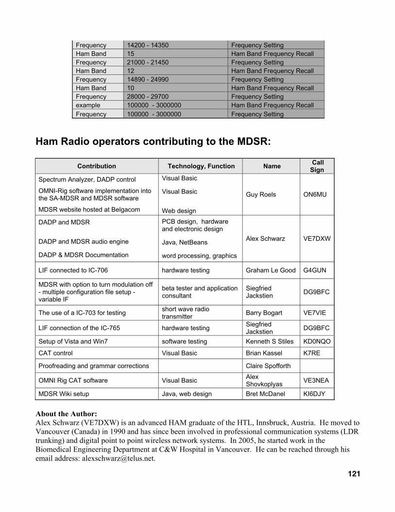
Frequency 14200 - 14350 Frequency Setting Ham Band 15 Ham Band Frequency Recall Frequency 21000 - 21450 Frequency Setting Ham Band 12 Ham Band Frequency Recall Frequency 14890 - 24990 Frequency Setting Ham Band 10 Ham Band Frequency Recall Frequency 28000 - 29700 Frequency Setting example 100000 - 3000000 Ham Band Frequency Recall Frequency 100000 - 3000000 Frequency Setting
Ham Radio operators contributing to the MDSR:
Contribution Technology, Function Name Call Sign
Spectrum Analyzer, DADP control
OMNI-Rig software implementation into the SA-MDSR and MDSR software
MDSR website hosted at Belgacom
Visual Basic Visual Basic Web design
Guy Roels ON6MU
DADP and MDSR DADP and MDSR audio engine DADP & MDSR Documentation
PCB design, hardware and electronic design Java, NetBeans word processing, graphics
Alex Schwarz VE7DXW
LIF connected to IC-706 hardware testing Graham Le Good G4GUN
MDSR with option to turn modulation off - multiple configuration file setup - variable IF
beta tester and application consultant
Siegfried Jackstien DG9BFC
The use of a IC-703 for testing short wave radio transmitter Barry Bogart VE7VIE
LIF connection of the IC-765 hardware testing Siegfried Jackstien DG9BFC
Setup of Vista and Win7 software testing Kenneth S Stiles KD0NQO
CAT control Visual Basic Brian Kassel K7RE
Proofreading and grammar corrections Claire Spofforth
OMNI Rig CAT software Visual Basic Alex Shovkoplyas VE3NEA
MDSR Wiki setup Java, web design Bret McDanel KI6DJY
About the Author: Alex Schwarz (VE7DXW) is an advanced HAM graduate of the HTL, Innsbruck, Austria. He moved to Vancouver (Canada) in 1990 and has since been involved in professional communication systems (LDR trunking) and digital point to point wireless network systems. In 2005, he started work in the Biomedical Engineering Department at C&W Hospital in Vancouver. He can be reached through his email address: [email protected].