modification of mechanistic-empirical pavement design ... · modification of mechanistic-empirical...
TRANSCRIPT
MODIFICATION OF MECHANISTIC-EMPIRICAL PAVEMENT DESIGN GUIDE PROCEDURE FOR TWO-LIFT COMPOSITE CONCRETE PAVEMENTS (12-2127) Derek Tompkins Research Associate University of Minnesota 500 Pillsbury Drive S.E. Minneapolis, MN 55455 Phone: 612-626-4098 E-mail: [email protected] Priyam Saxena Research Associate University of Minnesota 500 Pillsbury Drive S.E. Minneapolis, MN 55455 Phone: 612-625-1571 E-mail: [email protected]
Lev Khazanovich (corresponding) Associate Professor University of Minnesota Department of Civil Engineering 500 Pillsbury Drive S.E. Minneapolis, MN 55455 Phone: 612-624-4764 E-mail: [email protected] Alex Gotlif Research Engineer Applied Research Associates, Inc. 100 Trade Centre Drive, Suite 200 Champaign, IL 61820-7233 Phone: 217-356-4500 E-mail: [email protected]
Paper submitted 31 July 2011 for
Transportation Research Board 91st Annual Meeting, 22-26 January 2012
Words: 4817
Figures: 6 Tables: 3
Photographs: 0 Total Word Count: 7223
TRB 2012 Annual Meeting Paper revised from original submittal.

Tompkins, Saxena, Gotlif, and Khazanovich 1
MODIFICATION OF MECHANISTIC-EMPIRICAL PAVEMENT DESIGN GUIDE PROCEDURE FOR TWO-LIFT COMPOSITE CONCRETE PAVEMENTS (12-2127) ABSTRACT This paper describes modifications made to the Mechanistic-Empirical Pavement Design Guide (MEPDG) to accommodate the design of newly constructed composite PCC-PCC pavements. In previous versions of the MEPDG, a newly constructed PCC-PCC pavement project was considered as a bonded PCC overlay of an existing PCC pavement. Due to this simplification, the MEPDG was not self-consistent in its predictions for a newly constructed PCC-PCC pavement and its structurally equivalent single-layer analogue. To remedy this inconsistency, researchers suggested modifications to the Enhanced Integrated Climatic Model (EICM) used by the MEPDG in terms of 1) the number of locations through the slab used by EICM to determine the thermal gradient and 2) the EICM calculation of the subgrade spring stiffness (or k-value). The paper includes “before and after” MEPDG sensitivity analyses to justify the modifications developed and implemented into the MEPDG with the assistance of the MEPDG development team. This research was conducted under the Strategic Highway Research Program (SHRP2) R21 Composite Pavements project.
TRB 2012 Annual Meeting Paper revised from original submittal.

Tompkins, Saxena, Gotlif, and Khazanovich 2
INTRODUCTION The R21 project “Composite Pavements” was developed by the second generation of the Strategic Highway Research Program (SHRP2) to investigate the design and construction of new composite pavement systems. One fork of the R21 research focuses on a composite pavement system featuring a thin portland cement concrete (PCC) layer placed over another PCC layer. In Europe, two-layer composite PCC pavements (PCC-PCC) are more commonly used than they are in the United States. For instance, the standard concrete pavement in Austria is constructed according to two-layer PCC specifications. Furthermore, composite PCC pavements have been used in countries such as Switzerland, Belgium, the Netherlands, France, and Germany, and composite PCC pavements are becoming even more popular as design and construction techniques are refined further (1).
The goals of the SHRP2 R21 research were to determine the behavior and identify critical material and performance parameters for PCC-PCC; develop and validate performance models and design procedures consistent with the Mechanistic-Empirical Pavement Design Guide (MEPDG); and recommend specifications, construction techniques and quality management procedures.
In adopting the MEPDG for the design and analysis of newly constructed composite PCC-PCC pavements, an initial modeling simplification made by the MEPDG development team was to treat a newly constructed PCC-PCC composite pavement as a a bonded PCC-over-JPCP project. This change was implemented in MEPDG (beta versions 1.014:9030A and 1.206:R21), and research for the composite PCC-PCC portion of the R21 project that used the MEPDG simulated new PCC-PCC construction using a bonded PCC-over-JPCP project in the MEPDG.
However, the decision to use a bonded PCC overlay project to mirror new PCC-PCC construction introduced a number of challenges in modeling to the R21 research team. An important goal of the research described in this paper was the desire to overcome these challenges in a way that was compatible with the EICM and the MEPDG. In other words, the R21 research team sought to overcome any difficulties using only the existing framework of the MEPDG. While some may view this as a limitation, the R21 research team insisted on this condition knowing how robust MEPDG and EICM are.
The following sections will describe the research that uncovered and addressed the challenges in using MEPDG to design and predict the performance of newly constructed PCC-PCC by detailing:
1. How the MEPDG challenges addressed by the R21 research were first encountered. 2. The relevant sensitivity studies conducted to understand the models at work in MEPDG
and the Enhanced Integrated Climatic Model (EICM) used by MEPDG. 3. A brief overview of the MEPDG calculation of stresses for rigid pavements, with
particular emphasis on temperature curling stresses (given their relevance to this subject). 4. A few modeling simplifications made by EICM for bonded PCC overlay projects that the
R21 research team isolated as being potential sources of difficulty, and suggested revisions to EICM to adjust the models for the benefit of composite PCC pavements.
5. The implementation of these suggested revisions and a brief sensitivity study to examine the effect of these revisions on the MEPDG.
TRB 2012 Annual Meeting Paper revised from original submittal.
Tompkins, Saxena, Gotlif, and Khazanovich 3
PROBLEM FORMULATION The R21 research team initiated a number of experimental batch runs to gauge the fundamentals of the MEPDG in performance prediction for composite PCC-PCC pavements. One simple test of the MEPDG modeling was to create two projects describing the same PCC pavement, the only difference in the two projects being that one is a bonded PCC-over-JPCP project (MEPDG’s analogue to new PCC-PCC as discussed above) and the second is a single-layer JPCP pavement. The input parameters defining these two cases, and the layer properties themselves, are identical except for the layer thicknesses. The project inputs are briefly summarized in Table 1, where PCC properties listed are for single-layer project and both layers of two-lift project. Table 1. MEPDG inputs for basic sensitivity analysis project for R21 PCC-PCC investigation Design Life 20 years PCC Composite Thickness 9 in Location Florida, US-41 PCC Modulus of Rupture 650 psi Initial IRI 63 in/mi PCC Poisson’s ratio 0.2 Traffic 800 AADTT PCC Coefficient of thermal
expansion 5.5 x 10^-6 10-6/°F
Permanent Curl/Warp -10 °F PCC Thermal conductivity 1.25 Btu/(ft)(hr)(°F) Dowel spacing 12 in PCC Heat capacity 0.28 BTU/lb.-°F Dowel diameter 1.25 in PCC Unit weight 150 lb/ft3 Base 6 in, lime stabilized PCC Cement content 600 lb/yd3 Subbase 12 in, A-3 PCC w/c 0.42 These structurally identical projects were run through the MEPDG for identical traffic levels, climate, and design life. Table 2 reports results for this pair of pavements for MEPDG 1.014:9030A. Table 2. MEPDG 1.014:9030A predictions for performance of composite PCC-PCC and its single-layer structural equivalent Filename h (in) IRI (in/mi) % Slabs
Cracked Faulting (in) Bottom-up
Damage Top-down Damage
R21_P1.xls 9 67 0.4 0.006 0.0421 0.0431 R21_B1.xls 3 over 6 68.9 0.8 0.006 0.0223 0.0846 Abs % Diff in Pred Perf 2.8% 100% 0.0% 47.0% 96.3% This simple comparison of PCC-PCC and its single layer PCC equivalent revealed notable discrepancies in the predicted performance (particularly in damage due to top-down cracking). Again, these two pavements are structurally equivalent and should perform identically from a mechanistic point of view. While the empirical nature of the MEPDG prevents the predicted performance from being identical, it is reasonable to assume that performance of these pavements should have very small discrepancies. Table 2 illustrates that this is not the case.
As a result of this early observation, the R21 research team conducted a more extensive sensitivity analysis to better understand the differences in predicted performance for structurally equivalent two-lift and single-layer PCC pavements in the MEPDG.
TRB 2012 Annual Meeting Paper revised from original submittal.

Tompkins, Saxena, Gotlif, and Khazanovich 4
MEPDG SENSITIVITY ANALYSIS The R21 research team conducted an extensive sensitivity analysis using various beta versions of the MEPDG to differentiate between the modeling of composite PCC-PCC pavements (bonded PCC overlay) with their structurally equivalent single-layer JPCP counterparts. The factorials comprising the sensitivity analysis focused on variables including:
• Composite PCC layer thicknesses • Upper-lift PCC (overlay) flexural strength • Lower-lift PCC flexural strength • Upper-lift PCC coefficient of thermal expansion • Upper-lift PCC modulus of elasticity
While results from these factorials raised other questions on the models in the MEPDG, only results relevant to the matters discussed in this paper are presented here. A thorough discussion of the R21 MEPDG sensitivity analyses can be found in the final reporting for SHRP2 R21 Composite Pavements (2). Also note that the sensitivity analysis was conducted using two beta versions of the MEPDG for R21: version 1.013:9030A and version 1.206:R21. While the two versions produce different results, this is not due to changes in the EICM modeling, which was consistent for both versions and which was the focus of the research detailed here.
The most interesting of the sensitivity analysis cases were those in which only the thicknesses of the PCC-PCC composite layers were adjusted. These cases are compared with one another in Table 3. Table 3. Top-lift (PCC overlay) thickness and bottom-up damage, MEPDG v.1.014:9030A Filename h (in) IRI (in/mi) % Slabs
Cracked Faulting (in) Bottom-up
Damage Top-down Damage
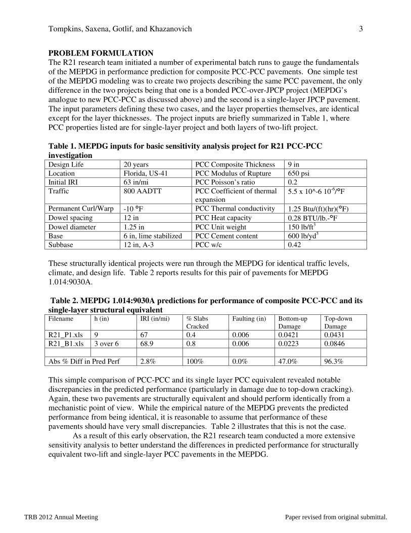
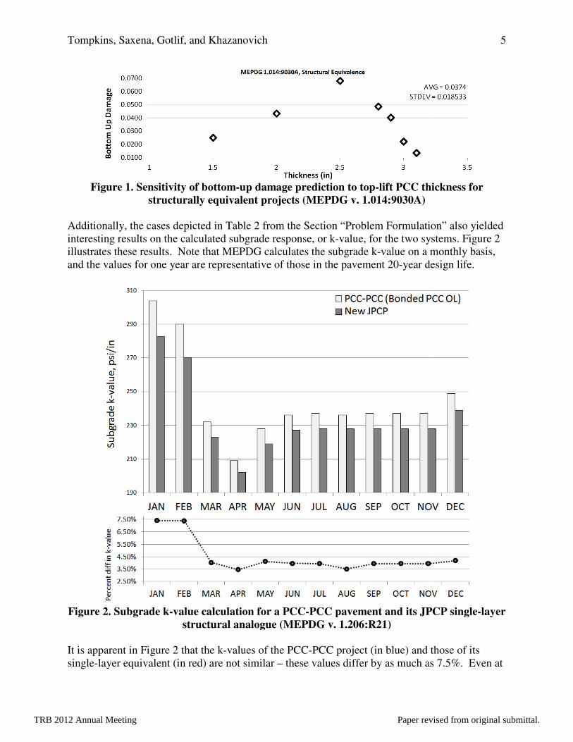
R21_B1.xls 3 over 6 68.9 0.8 0.006 0.0223 0.0846 R21_B1a.xls 3.1 over 5.9 69.1 0.6 0.005 0.0136 0.074 R21_B1c.xls 2.9 over 6.1 69.4 0.7 0.006 0.0404 0.0722 R21_B1d.xls 2.8 over 6.2 69.4 0.8 0.006 0.0488 0.0715 R21_B1e.xls 2.5 over 6.5 69.4 0.9 0.006 0.0681 0.0624 R21_B1f.xls 2 over 7 69.3 0.8 0.006 0.0434 0.075 R21_B1g.xls 1.5 over 7.5 68.8 0.8 0.006 0.0252 0.0808 Both the damage due to bottom-up cracking and top-down cracking vary unreasonably for such small changes to PCC lift thickness. Simple observation of the bottom-up damage reveals inherent modeling contradictions. All of the structures in Table 3 are structurally equivalent – we would expect that no matter the layer thicknesses, the projects would experience the same amount of damage under the same conditions and traffic. However, according to the initial models used for MEPDG R21, a PCC-PCC with top-lift thickness of 2.5 inches experiences five times the bottom-up damage as a structurally equivalent PCC-PCC with top-lift thickness of 3.1 inches. This is equivalent to saying that in terms of bottom-up damage, it is as if the 2.5 inch structural equivalent has experienced five times the level of traffic as the other projects. The variability in the bottom-up damage predictions for the thickness sensitivity study is illustrated more closely in Figure 1.
TRB 2012 Annual Meeting Paper revised from original submittal.
Tompkins, Saxena, Gotlif, and Khazanovich
Figure 1. Sensitivity of bottomstructurally equivalent projects
Additionally, the cases depicted in interesting results on the calculated subgrade response, or killustrates these results. Note that MEPDG calculates the subgrade kand the values for one year are representative o
Figure 2. Subgrade k-value calculation for a PCCstructural analogue
It is apparent in Figure 2 that the ksingle-layer equivalent (in red) are not similar
Tompkins, Saxena, Gotlif, and Khazanovich
Sensitivity of bottom-up damage prediction to top-lift PCC thickness structurally equivalent projects (MEPDG v. 1.014:9030A)
Additionally, the cases depicted in Table 2 from the Section “Problem Formulation” interesting results on the calculated subgrade response, or k-value, for the two systems. illustrates these results. Note that MEPDG calculates the subgrade k-value on a monthly basis,
for one year are representative of those in the pavement 20-year design life.
value calculation for a PCC-PCC pavement and its JPCP singlestructural analogue (MEPDG v. 1.206:R21)
that the k-values of the PCC-PCC project (in blue) and those of its layer equivalent (in red) are not similar – these values differ by as much as 7.5%. Even at
5
lift PCC thickness for
from the Section “Problem Formulation” also yielded value, for the two systems. Figure 2
value on a monthly basis, year design life.
PCC pavement and its JPCP single-layer
PCC project (in blue) and those of its iffer by as much as 7.5%. Even at
TRB 2012 Annual Meeting Paper revised from original submittal.

Tompkins, Saxena, Gotlif, and Khazanovich 6
the most similar, the two k-values diverge by 3.5%, which is not a trivial (or “almost identical”) difference. These results suggested to the R21 research team that the EICM subgrade reaction calculation was deserving of further attention.
The sensitivity analysis presented above clearly indicates that an analysis of identical structures performed by the MEPDG leads to different characterizations of the structures and, subsequently, performance predictions. A detailed analysis of the MEPDG temporary project files identified problems in the interaction of the EICM with the stress analysis routines. To address this issue the stress analysis of the multi-layered JPCP pavements in the MEPDG was first re-considered. The research team then proceeded to develop modifications to the EICM to better interact with the MEPDG stress analysis routines. The following sections detail the relevant MEPDG stress calculation routines and then the relevant EICM routines. MEPDG STRESS CALCULATION The MEPDG stress analysis of rigid pavements is based on the:
• Slab equivalency concept, and • Use of artificial neural networks
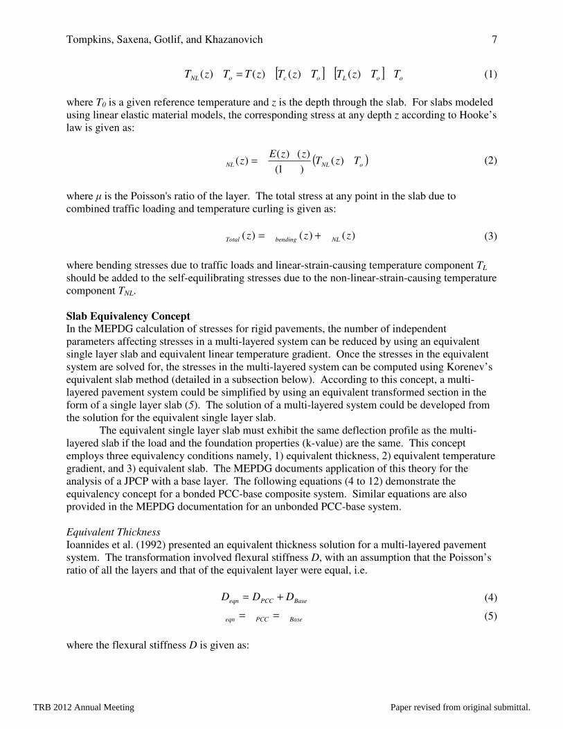
The following subsections describe the slab equivalence concept, which was adopted by the MEPDG to reduce the number of independent parameters affecting PCC stresses without introducing any additional error. A main component of the stresses in a rigid system is stress due to temperature curling, and given that suggested EICM revisions later detailed in this paper deal with the distribution of temperature through a single-layer or two-layer PCC slab, thermal stresses in rigid systems are also briefly reviewed. Stresses Due to Temperature Curling Rigid and composite pavements are subjected to bending stresses under temperature gradients and traffic loads. Khazanovich (1994) demonstrated the existence of an additional stress attributed to the non-linear temperature distribution through a PCC layer that acts on single or multi-layered pavement systems so as to produce stresses that are self-equilibrating in nature. Consider a slab on an elastic foundation subjected to an arbitrary temperature distribution. The arbitrary temperature distribution may be linear or non-linear through the thickness of the slab but does not vary in the plane of the slab, and the slab is free to contract or expand in the horizontal directions. According to Thomlinson (1940) any arbitrary temperature distribution, T(z) can be divided into a constant-strain-causing temperature component, TC, a linear-strain-causing temperature component, TL, and a nonlinear-strain-causing temperature component, TNL. Each of these three components may vary through the depth of the slab, z, along with the temperature T(z). The constant-strain-causing temperature component, TC, produces horizontal strains that are constant through the depth of the slab. These strains do not produce stress when the slab is unrestrained in the horizontal directions. The linear-strain-causing temperature component, TL, produces horizontal strains that are linearly distributed along the depth of the slab. TL produces bending stresses that can be solved for by using any finite element (FE)-based method. Given the constant and linear strain-causing temperature components, TL and TC, the nonlinear-strain-causing temperature component, TNL, can be written as:
TRB 2012 Annual Meeting Paper revised from original submittal.
Tompkins, Saxena, Gotlif, and Khazanovich 7
(1)
where T0 is a given reference temperature and z is the depth through the slab. For slabs modeled using linear elastic material models, the corresponding stress at any depth z according to Hooke’s law is given as:
(2)
where µ is the Poisson's ratio of the layer. The total stress at any point in the slab due to combined traffic loading and temperature curling is given as:
(3)
where bending stresses due to traffic loads and linear-strain-causing temperature component TL should be added to the self-equilibrating stresses due to the non-linear-strain-causing temperature component TNL. Slab Equivalency Concept In the MEPDG calculation of stresses for rigid pavements, the number of independent parameters affecting stresses in a multi-layered system can be reduced by using an equivalent single layer slab and equivalent linear temperature gradient. Once the stresses in the equivalent system are solved for, the stresses in the multi-layered system can be computed using Korenev’s equivalent slab method (detailed in a subsection below). According to this concept, a multi-layered pavement system could be simplified by using an equivalent transformed section in the form of a single layer slab (5). The solution of a multi-layered system could be developed from the solution for the equivalent single layer slab. The equivalent single layer slab must exhibit the same deflection profile as the multi-layered slab if the load and the foundation properties (k-value) are the same. This concept employs three equivalency conditions namely, 1) equivalent thickness, 2) equivalent temperature gradient, and 3) equivalent slab. The MEPDG documents application of this theory for the analysis of a JPCP with a base layer. The following equations (4 to 12) demonstrate the equivalency concept for a bonded PCC-base composite system. Similar equations are also provided in the MEPDG documentation for an unbonded PCC-base system. Equivalent Thickness Ioannides et al. (1992) presented an equivalent thickness solution for a multi-layered pavement system. The transformation involved flexural stiffness D, with an assumption that the Poisson’s ratio of all the layers and that of the equivalent layer were equal, i.e.
(4)
(5)
where the flexural stiffness D is given as:
[ ] [ ] ooLocoNL TTzTTzTzTTzT -----=- )()()()(
( )oNLNL TzTzzE
z --
-= )()1(
)()()(
mas
)()()( zzz NLbendingTotal sss +=
BasePCCeqn DDD +=
BasePCCeqn mmm ==
TRB 2012 Annual Meeting Paper revised from original submittal.

Tompkins, Saxena, Gotlif, and Khazanovich 8
(6)
where: E, h, µ = Young’s modulus, layer thickness, Poisson’s ratio (respectively) According to Khazanovich (1994) the governing equation of the transformation (equation 4) can also be written in terms of moment in each plate M, as follows:
(7)
For a fully bonded PCC-base system, the neutral axis of the bonded system, assuming the origin is at the top of the PCC layer, is given as follows:
(8)
where: x = location of the neutral axis from the top of PCC layer The thickness and modulus of the equivalent single layer slab can be established in terms of the thicknesses and moduli of the corresponding multi-layered slab by combining equations (4) to (8) as follows:
(9)
For a fully bonded PCC-PCC-base system, the neutral axis x is located as follows, assuming the origin is located at the surface of the upper lift PCC layer:
BasePCC
BasePCCPCC
PCC
PCC
BasePCCPCCBase
PCC
BasePCCPCCPCC
PCC
PCC
PCC
hE
Ehh
E
E
hhhh
E
Ehhh
h
E
E
x
221
2
1
212
212
21
2
1
222
++
+++
++=
(10)
)1(12 2
3
m-=
hED
BasePCCeqn MMM +=
BaseBasePCCPCC
BasePCCBaseBase
PCCPCCPCC
h
h
hEhE
hhhE
hhE
dzzE
zdzzE
x+
++
==
∫
∫ 22
)(
)(
0
0
-++
-++=22
333
2212 x
hhhEx
hhEhEhEhE Base
PCCBaseBasePCC
PCCPCCBaseBasePCCPCCeffeff
TRB 2012 Annual Meeting Paper revised from original submittal.
Tompkins, Saxena, Gotlif, and Khazanovich 9
where and Eeff, EPCC1, EPCC2, and EBase are the Young’s moduli of the effective composite system, upper-lift PCC, lower-lift PCC, and base layers, respectively, and heq, hPCC1, hPCC2, and hBase are the thicknesses of the effective composite slab, upper-lift PCC, lower-lift PCC, and base layers, respectively. One check of the solution for the neutral axis in the three-layer PCC system is to consider that if EPCC1 = EPCC2, equation (10) will reduce to equation (8), which represents the location of the neutral axis in a single-layer PCC over base layer system. The thickness and modulus of the equivalent single-layer slab for the three-layer system can be established as in equation (9), where
-+++
-++
-
+++=2
21
2
2122
2
111
3322
311
3
22212 x
hhhhEx
hhhE
hxhE
hEhEhEhE
BasePCCPCCBaseBase
PCCPCCPCCPCC
PCCPCCPCC
BaseBasePCCPCCPCCPCCeffeff
(11)
All variables in equation (11) are defined above for equation (10). Equivalent Linear Temperature Gradient Thomlinson (1940) introduced the concept of equivalent temperature gradient for a single-layer slab. Khazanovich (1994) and Ioannides and Khazanovich (1998) later generalized the concept for a non-uniform, multi-layered slab. The MEPDG documentation states that “if two slabs have the same plane-view geometry, flexural stiffness, self-weight, boundary conditions, and applied pressure, and rest on the same foundation, then these slabs have the same deflection and bending moment distributions if their through-the-thickness temperature distributions satisfy the following condition” (7):
(12)
where
A and B = subscripts denoting the two slabs z = distance from the neutral axis T0 = temperature at which theses slabs are assumed to be flat α = coefficient of thermal expansion E = modulus of elasticity h = slab thickness
Khazanovich (1994) also states that “[A]s a corollary, two temperature distributions are equivalent only if their respective linear strain components are identical.” Therefore, equation (12) can be employed for the curling analysis of a multi-layered slab in terms of the curling analysis of a single-layer equivalent slab. The temperature distribution in the single-layer equivalent slab is chosen to be a linear function of depth and can be expressed in terms of temperature distributions of the PCC and base layers as follows:
∫∫ -=-BA h
BBBB
h
AAAA zdzTzTzzEzdzTzTzzE ))()(()())()(()( ,0,0 aa
TRB 2012 Annual Meeting Paper revised from original submittal.
Tompkins, Saxena, Gotlif, and Khazanovich 10
(13)
where: ΔTL,eff = difference between the top and bottom surface temperatures of the equivalent
slab T(z) and To = temperature distributions and reference temperature respectively, αPCC and αBase = coefficients of thermal expansion of the PCC and base layers,
respectively For a fully bonded PCC-PCC-base system, the temperature distribution in the single-layer equivalent slab is chosen to be a linear function of depth and can be expressed in terms of temperature distributions of the PCC and base layers as follows:
[ ] [ ]
[ ]
-+
-+--=D
∫
∫∫-++
-+
-+
-
-
-
xhhh
xhh
oBasePCCPCC
BaseBase
xhh
xh
oPCC
xh
x
oPCCPCCPCC
PCCPCC
effeffL
BasePCCPCC
PCCPCC
PCCPCC
PCC
PCC
zdzTzTE
E
zdzTzTzdzTzTE
E
hT
21
21
21
1
1
)(
)()(12
22
2122
11
2,
aa
aa
(14) where ΔTL,eff = difference between the top and bottom surface temperatures of the equivalent
slab T(z), ToPCC1, ToPCC2, ToBASE = temperature distribution and reference temperatures for
respective PCC and base layers αPCC1, αPCC2, and αBase = coefficients of thermal expansion of the PCC and base layers,
respectively EPCC1, EPCC2, and EBase = Young’s moduli of the PCC and base layers, respectively hPCC1, hPCC2, and hBase = thicknesses PCC and base layers, respectively heff = effective thickness of equivalent single-layer system One can observe that if EPCC1 = EPCC2 then the solution for the 3-layered system in equation (14) should coincide with the solution for a single layer system in equation (13). Equivalent Slab According to Korenev Korenev and Chernigovskaya (1962) proposed an equivalency concept for circular slabs resting on a Winkler foundation and subjected to traffic loads and temperature curling. According to this concept, the stress distribution in a slab of known dimensions, properties, loading conditions, and temperature gradients is related to the stress distribution in another slab by equation (15), if the following are the same (9):
• Ratio of the slab characteristic dimension to the radius of relative stiffness (L/l), • The total applied load to the slab self-weight (P/Q), and • Korenev’s non-dimensional temperature gradient .
[ ] [ ]
-+--=D ∫∫
-+
-
-
-
xhh
xh
oPCCPCC
BaseBasexh
x
oeff
effL
BasePCC
PCC
PCC
zdzTzTE
EzdzTzT
hT )()(
122, a
a
f
TRB 2012 Annual Meeting Paper revised from original submittal.

Tompkins, Saxena, Gotlif, and Khazanovich 11
(15)
where: σ, h, γ, and l = temperature stress, thickness, unit-weight, and radius of relative stiffness
of a given slab, respectively The MEPDG adopts the Korenev’s non-dimensional temperature gradient to combine many factors that affect curling stresses into one parameter (7, 9). It is defined as:
(16)
where: α, µ, l, γ, h = coefficient of thermal expansion, Poisson’s ratio, radius of relative stiffness,
unit-weight, and thickness of the slab, respectively k = modulus of subgrade reaction ∆TL = linear temperature difference between the top and bottom surface of the slab Korenev’s slab equivalency concept was modified for the analysis of rectangular slabs. It was found that if the following conditions are fulfilled, then the concept holds true for rectangular slabs as well (7):
(17)
where:
� = � �������� �
�, the stiffness of the slab relative to the foundation stiffness
E, h, µ = PCC modulus of elasticity, thickness, Poisson’s ratio L = joint spacing
= Korenev’s nondimensional temperature gradient AGG = aggregate interlock between the main lane and the shoulder P = axle weight γ = PCC slab unit weight s = distance between slab edge and outer wheel edge
22221
2112
1 sggs
lh
lh=
LTk
h
l D+=g
maf2
2)1(2
21
22
2
11
1
22
2
11
1
21
21
21
ss
h
P
h
P
lk
AGG
lk
AGG
LL
ll
=
=
=
==
=
gg
ff
f
TRB 2012 Annual Meeting Paper revised from original submittal.
Tompkins, Saxena, Gotlif, and Khazanovich 12
EICM TEMPERATURE DISTRIBUTION CHARACTERIZATION EICM Representation of a Thermal Gradient through a Composite Pavement System As noted in Table B in Section “MEPDG Sensitivity Analysis,” the R21 research team found that there existed a lurking variable not accessible to MEPDG users that has to do with layer thickness on the newly constructed PCC-PCC project. The research team could detect problems through MEPDG batch runs, but could not truly illuminate or diagnose these problems without the MEPDG source code. However, in discussions with the MEPDG developers, the R21 research team hypothesized that the effects at work in Table B were likely due to the nature of the EICM thermal analysis for a rigid pavement.
In the original EICM thermal analysis (version 1.003 and versions prior to 1.014:9030A), 10 nodes were distributed through the PCC slab with an additional node at the bottom of the base layer, resulting in a total of 11 nodes used to represent the temperature through the PCC slab and base with respect to a reference temperature (10-12). This distribution of nodes was then used to calculate the nonlinear stresses at the top and bottom of the slabs for damage calculations, as detailed in the section “MEPDG Stress Calculation” above.
In the revised EICM thermal analysis in versions 1.014:9030A and 1.206:R21 for SHRP2 R21, rather than the 10 nodes being applied to the entire composite slab (approximated by the bonded PCC overlay project), the MEPDG developers assigned each layer of the slab 10 nodes, which results in the use of a minimum of 20 temperature nodes for the entire slab and base (13). These additional nodes present two key challenges. The first is that their inclusion dramatically increases the run-time for the damage calculation in the PCC-PCC pavement. The second, and more important, challenge is that the system with additional nodes threatens the self-consistency of the MEPDG, as evidenced by the results in Table 2. As noted above, for a single-layer PCC pavement, EICM uses only 10 nodes. For a new PCC-PCC pavement, the thermal gradient is approximated by EICM using 20 or more nodes through the composite slab. This modeling difference ripples though the project runs and provides results for structurally equivalent systems that are significantly different where they should instead be nearly identical.
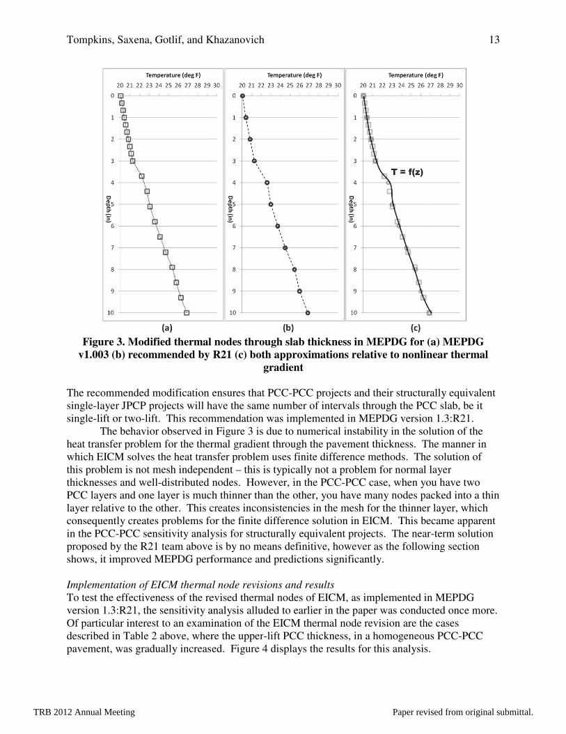
The R21 research team recommended to the MEPDG developer that the thermal gradient for a bonded PCC overlay should be modified to use PCC layer thicknesses and the base layer thickness to develop 11 equally spaced nodes through the composite slab and a twelfth node at the bottom of the base layer, thereby creating 10 intervals in the composite slab and one for the base layer. The thermal node arrangement used in MEPDG versions 1.014:9030A and 1.206:R21 is described in Figure 3a. The R21 recommended thermal node arrangement (used in MEPDG 1.3:R21) is described in Figure 3b.
TRB 2012 Annual Meeting Paper revised from original submittal.
Tompkins, Saxena, Gotlif, and Khazanovich
Figure 3. Modified thermal nodes through slab thickness in MEPDGv1.003 (b) recommended by R21 (c) both approximation
The recommended modification ensuressingle-layer JPCP projects will have the same number of intervals through the PCC slab, be it single-lift or two-lift. This recommendation was implemented in MEPDG version 1.
The behavior observed in Figure heat transfer problem for the thermal gradient through the pavement thicknesswhich EICM solves the heat transfer problem usesthis problem is not mesh independent thicknesses and well-distributed nodes. PCC layers and one layer is much tlayer relative to the other. This creates inconsistencies in the mesh for the thinner layer, which consequently creates problems for the finite difference solution in EICM. This became apparenin the PCC-PCC sensitivity analysis for structurally equivalent projects. The nearproposed by the R21 team aboveshows, it improved MEPDG performance and predictions significantl Implementation of EICM thermal node revisions and resultsTo test the effectiveness of the revised thermal nodes of EICM, as implemented in MEPDG version 1.3:R21, the sensitivity analysis alluded to earlier in the paper was conducted once more. Of particular interest to an examination of the EICM thermal node revision are the cases described in Table 2 above, where the upperpavement, was gradually increased.
Tompkins, Saxena, Gotlif, and Khazanovich
Modified thermal nodes through slab thickness in MEPDG for (a) MEPDG (b) recommended by R21 (c) both approximations relative to nonlinear thermal
gradient
The recommended modification ensures that PCC-PCC projects and their structurally equivalent layer JPCP projects will have the same number of intervals through the PCC slab, be it
lift. This recommendation was implemented in MEPDG version 1.rved in Figure 3 is due to numerical instability in the solution of the
heat transfer problem for the thermal gradient through the pavement thickness. The the heat transfer problem uses finite difference methods. The solution of
this problem is not mesh independent – this is typically not a problem for normal layer distributed nodes. However, in the PCC-PCC case, when you have two
PCC layers and one layer is much thinner than the other, you have many nodes packed into a thin layer relative to the other. This creates inconsistencies in the mesh for the thinner layer, which
problems for the finite difference solution in EICM. This became apparenPCC sensitivity analysis for structurally equivalent projects. The near
above is by no means definitive, however as the following section shows, it improved MEPDG performance and predictions significantly.
Implementation of EICM thermal node revisions and results To test the effectiveness of the revised thermal nodes of EICM, as implemented in MEPDG version 1.3:R21, the sensitivity analysis alluded to earlier in the paper was conducted once more.
ticular interest to an examination of the EICM thermal node revision are the cases above, where the upper-lift PCC thickness, in a homogeneous PCC
pavement, was gradually increased. Figure 4 displays the results for this analysis.
13
for (a) MEPDG
relative to nonlinear thermal
PCC projects and their structurally equivalent layer JPCP projects will have the same number of intervals through the PCC slab, be it
lift. This recommendation was implemented in MEPDG version 1.3:R21. in the solution of the
. The manner in finite difference methods. The solution of
this is typically not a problem for normal layer PCC case, when you have two
hinner than the other, you have many nodes packed into a thin layer relative to the other. This creates inconsistencies in the mesh for the thinner layer, which
problems for the finite difference solution in EICM. This became apparent PCC sensitivity analysis for structurally equivalent projects. The near-term solution
is by no means definitive, however as the following section
To test the effectiveness of the revised thermal nodes of EICM, as implemented in MEPDG version 1.3:R21, the sensitivity analysis alluded to earlier in the paper was conducted once more.
ticular interest to an examination of the EICM thermal node revision are the cases lift PCC thickness, in a homogeneous PCC-PCC displays the results for this analysis.
TRB 2012 Annual Meeting Paper revised from original submittal.
Tompkins, Saxena, Gotlif, and Khazanovich
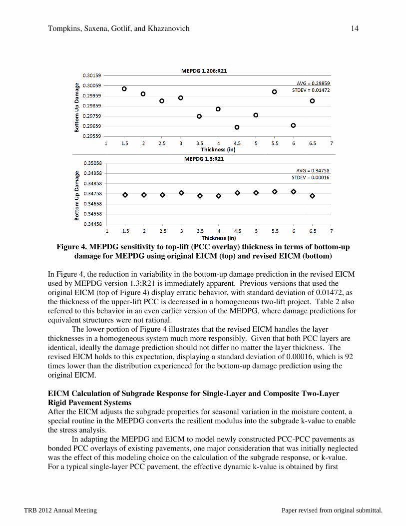
Figure 4. MEPDG sensitivity to tdamage for MEPDG using original EICM (top) and revised EICM (bottom)
In Figure 4, the reduction in variability in the used by MEPDG version 1.3:R21 is immediately apparent. Previous versions that used the original EICM (top of Figure 4) display erratic behavior, with standard deviation of 0.01472, as the thickness of the upper-lift PCC is referred to this behavior in an even earlier version of the MEDPGequivalent structures were not rational.
The lower portion of Figure 4thicknesses in a homogeneous system much more responsibly. Given that both PCC layers are identical, ideally the damage prediction revised EICM holds to this expectation, displaying a times lower than the distribution experienced for the original EICM. EICM Calculation of Subgrade Rigid Pavement Systems After the EICM adjusts the subgrade properties for seasonal variation in the moisture content, a special routine in the MEPDG converts the resilient modulus into the subgrade kthe stress analysis.
In adapting the MEPDG and EICM to model newly constructed PCCbonded PCC overlays of existing pavements, one major consideration that was initially neglected was the effect of this modeling choice on the calcFor a typical single-layer PCC pavement, t
Tompkins, Saxena, Gotlif, and Khazanovich
MEPDG sensitivity to top-lift (PCC overlay) thickness in terms of for MEPDG using original EICM (top) and revised EICM (bottom)
, the reduction in variability in the bottom-up damage prediction in the revised EICM used by MEPDG version 1.3:R21 is immediately apparent. Previous versions that used the
) display erratic behavior, with standard deviation of 0.01472, as lift PCC is decreased in a homogeneous two-lift project.
in an even earlier version of the MEDPG, where damage predictions for equivalent structures were not rational.
Figure 4 illustrates that the revised EICM handles the layer thicknesses in a homogeneous system much more responsibly. Given that both PCC layers are
prediction should not differ no matter the layer thickness. The revised EICM holds to this expectation, displaying a standard deviation of 0.00016, which is 92 times lower than the distribution experienced for the bottom-up damage prediction using the
EICM Calculation of Subgrade Response for Single-Layer and Composite Two
After the EICM adjusts the subgrade properties for seasonal variation in the moisture content, a special routine in the MEPDG converts the resilient modulus into the subgrade k
In adapting the MEPDG and EICM to model newly constructed PCC-PCC pavements as bonded PCC overlays of existing pavements, one major consideration that was initially neglected
choice on the calculation of the subgrade response, or klayer PCC pavement, the effective dynamic k-value is obtained by first
14
in terms of bottom-up
for MEPDG using original EICM (top) and revised EICM (bottom)
prediction in the revised EICM used by MEPDG version 1.3:R21 is immediately apparent. Previous versions that used the
) display erratic behavior, with standard deviation of 0.01472, as lift project. Table 2 also
damage predictions for
EICM handles the layer thicknesses in a homogeneous system much more responsibly. Given that both PCC layers are
layer thickness. The standard deviation of 0.00016, which is 92
prediction using the
Layer and Composite Two-Layer
After the EICM adjusts the subgrade properties for seasonal variation in the moisture content, a special routine in the MEPDG converts the resilient modulus into the subgrade k-value to enable
PCC pavements as bonded PCC overlays of existing pavements, one major consideration that was initially neglected
ulation of the subgrade response, or k-value. value is obtained by first
TRB 2012 Annual Meeting Paper revised from original submittal.
Tompkins, Saxena, Gotlif, and Khazanovich 15
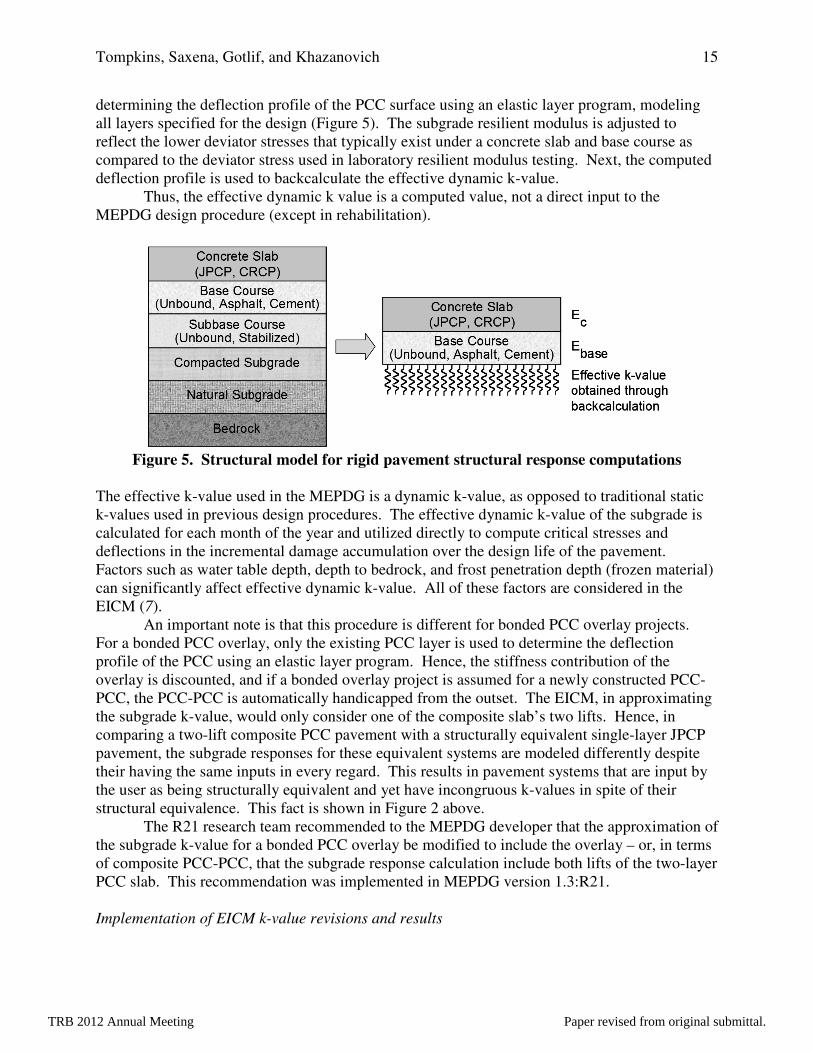
determining the deflection profile of the PCC surface using an elastic layer program, modeling all layers specified for the design (Figure 5). The subgrade resilient modulus is adjusted to reflect the lower deviator stresses that typically exist under a concrete slab and base course as compared to the deviator stress used in laboratory resilient modulus testing. Next, the computed deflection profile is used to backcalculate the effective dynamic k-value.
Thus, the effective dynamic k value is a computed value, not a direct input to the MEPDG design procedure (except in rehabilitation).
Figure 5. Structural model for rigid pavement structural response computations
The effective k-value used in the MEPDG is a dynamic k-value, as opposed to traditional static k-values used in previous design procedures. The effective dynamic k-value of the subgrade is calculated for each month of the year and utilized directly to compute critical stresses and deflections in the incremental damage accumulation over the design life of the pavement. Factors such as water table depth, depth to bedrock, and frost penetration depth (frozen material) can significantly affect effective dynamic k-value. All of these factors are considered in the EICM (7).
An important note is that this procedure is different for bonded PCC overlay projects. For a bonded PCC overlay, only the existing PCC layer is used to determine the deflection profile of the PCC using an elastic layer program. Hence, the stiffness contribution of the overlay is discounted, and if a bonded overlay project is assumed for a newly constructed PCC-PCC, the PCC-PCC is automatically handicapped from the outset. The EICM, in approximating the subgrade k-value, would only consider one of the composite slab’s two lifts. Hence, in comparing a two-lift composite PCC pavement with a structurally equivalent single-layer JPCP pavement, the subgrade responses for these equivalent systems are modeled differently despite their having the same inputs in every regard. This results in pavement systems that are input by the user as being structurally equivalent and yet have incongruous k-values in spite of their structural equivalence. This fact is shown in Figure 2 above.
The R21 research team recommended to the MEPDG developer that the approximation of the subgrade k-value for a bonded PCC overlay be modified to include the overlay – or, in terms of composite PCC-PCC, that the subgrade response calculation include both lifts of the two-layer PCC slab. This recommendation was implemented in MEPDG version 1.3:R21. Implementation of EICM k-value revisions and results
TRB 2012 Annual Meeting Paper revised from original submittal.
Tompkins, Saxena, Gotlif, and Khazanovich
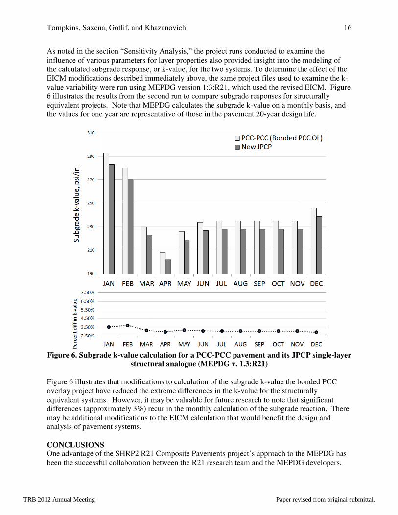
As noted in the section “Sensitivity Analysis,” the project runs conducted to examine the influence of various parameters for layer properties also provided insight into the modeling of the calculated subgrade response, or kEICM modifications described immediately above, the same project files used to examine the kvalue variability were run using MEPDG version 1:3:R21, which used the revised EICM. 6 illustrates the results from the second run to compare subgrade responses for structurally equivalent projects. Note that MEPDG calculates the subgrade kthe values for one year are representative of those in the pavem
Figure 6. Subgrade k-value calculation for a PCCstructural analogue (MEPDG v. 1.3:R21)
Figure 6 illustrates that modifications to calculation of the subgrade koverlay project have reduced the extreme differences in the equivalent systems. However, it may be valuable for future research to note that significant differences (approximately 3%) recur in the monthly calculation of the subgradmay be additional modifications to the EICM calculation that would benefit the design and analysis of pavement systems. CONCLUSIONS One advantage of the SHRP2 R21 Composite Pavements project’s approach to the MEPDG has been the successful collaboration between the R21 research team and the MEPDG developers.
Tompkins, Saxena, Gotlif, and Khazanovich
s noted in the section “Sensitivity Analysis,” the project runs conducted to examine the influence of various parameters for layer properties also provided insight into the modeling of
response, or k-value, for the two systems. To determine the effect of the EICM modifications described immediately above, the same project files used to examine the kvalue variability were run using MEPDG version 1:3:R21, which used the revised EICM.
illustrates the results from the second run to compare subgrade responses for structurally Note that MEPDG calculates the subgrade k-value on a monthly basis, and
the values for one year are representative of those in the pavement 20-year design life.
value calculation for a PCC-PCC pavement and its JPCP singlestructural analogue (MEPDG v. 1.3:R21)
illustrates that modifications to calculation of the subgrade k-value the bonded PCC ay project have reduced the extreme differences in the k-value for the structurally
equivalent systems. However, it may be valuable for future research to note that significant differences (approximately 3%) recur in the monthly calculation of the subgrade reaction. There may be additional modifications to the EICM calculation that would benefit the design and
One advantage of the SHRP2 R21 Composite Pavements project’s approach to the MEPDG has been the successful collaboration between the R21 research team and the MEPDG developers.
16
s noted in the section “Sensitivity Analysis,” the project runs conducted to examine the influence of various parameters for layer properties also provided insight into the modeling of
To determine the effect of the EICM modifications described immediately above, the same project files used to examine the k-value variability were run using MEPDG version 1:3:R21, which used the revised EICM. Figure
illustrates the results from the second run to compare subgrade responses for structurally value on a monthly basis, and
year design life.
PCC pavement and its JPCP single-layer
value the bonded PCC value for the structurally
equivalent systems. However, it may be valuable for future research to note that significant e reaction. There
may be additional modifications to the EICM calculation that would benefit the design and
One advantage of the SHRP2 R21 Composite Pavements project’s approach to the MEPDG has been the successful collaboration between the R21 research team and the MEPDG developers.
TRB 2012 Annual Meeting Paper revised from original submittal.

Tompkins, Saxena, Gotlif, and Khazanovich 17
This collaboration ensured that the R21 research team made recommendations for the MEPDG that were 100% compatible with the existing MEPDG and EICM. Furthermore, the research relationship between R21 and the MEPDG developers ensured that suggested modifications were implemented in the MEPDG with relative ease.
There are other advantages to the modifications suggested by the R21 research team and implemented by the MEPDG developers. For instance, the above modifications to the MEPDG not only produced better agreement between composite PCC-PCC and structurally equivalent single-layer PCC systems, they also led to computational benefits for the EICM and MEPDG. The modification to the number of thermal nodes required the EICM to use half the thermal nodes it previously did in determining climatic effects for every hour, day, month, and year of the pavement’s design life. This correspondingly decreased the MEPDG run-time for relevant projects.
The research performed and implemented into the MEPDG was done so for the sake of SHRP2 R21 and newly constructed composite PCC pavements. This research is not intended to account for bonded PCC overlay projects – rather, the adjustments were conducted only due to the MEPDG treating PCC-PCC as a bonded PCC overlay as a modeling simplification. Future versions of the MEPDG (or DARWin-ME) may choose to fully dedicate a project type to newly constructed PCC-PCC pavements.
Finally, the authors encourage AASHTO and the MEPDG developers to incorporate the R21 modifications for PCC-PCC modeling into the publically available version of the MEPDG/DARWin-ME. A future direction for the incorporation of these models into the latest version of the MEPDG or DARWin-ME might also involve further model validation and calibration as a worthwhile research goal. ACKNOWLEDGEMENTS The authors acknowledge the support of the Strategic Highway Research Program Project R21. Dr. James Bryant is the SHRP2 R21 Project Manager. The authors would like to thank Applied Research Associates, Inc., for their assistance throughout the development of the research detailed in this paper, and the authors thank in particular the following ARA personnel: R21 principal investigator Dr. Michael I. Darter, R21 internal project manager Dr. Shreenath Rao, and MEPDG software and development leader, Mr. Greg Larson. REFERENCES 1. Tompkins, D, L. Khazanovich, M.I. Darter, and W. Fleisher. Design and Construction of
Sustainable Pavements: Austrian and German Two-Layer Concrete Pavements. Transportation Research Record, No. 2098, Transportation Research Board of the National Academies, Washington D.C., 2009, p.75-85.
2. Strategic Highway Research Program. Final Report, Project R21 Composite Pavements. National Academy of Sciences, Washington D.C. 2011. In publication.
3. Khazanovich, L. Structural Analysis of Multi-Layered Concrete Pavement Systems. Ph.D. Dissertation, University of Illinois, Urbana, IL 1994.
TRB 2012 Annual Meeting Paper revised from original submittal.

Tompkins, Saxena, Gotlif, and Khazanovich 18
4. Thomlinson J. Temperature Variations and Consequent Stresses Produced by Daily and Seasonal Temperature Cycles in Concrete Slabs. Concrete Constructional Engineering, Vol. 36, No. 6, pp. 298-307; No. 7, pp. 352-360, 1940.
5. Ioannides A. M., Khazanovich L., and Becque J. L. Structural Evaluation of Base Layers in Concrete Pavement Systems. Transportation Research Record 1370, Washington D. C. 1992.
6. Ioannides, A. M., and L. Khazanovich. Nonlinear Temperature Effects in Multi-Layered Concrete Pavements. ASCE Journal of Transportation Engineering, Vol. 124, No. 2, 1998, pp. 128–136.
7. American Association of State Highway and Transportation Officials. Mechanistic-Empirical Pavement Design Guide, Interim Edition: A Manual of Practice. Washington, D.C. 2008.
8. Korenev B. G. and Chernigovskaya E. I. Analysis of Plates on Elastic Foundation, Gosstroiizdat, Moscow (in Russian), 1962.
9. Khazanovich L., Selezneva O. I., Yu H. T., and Darter M. I. Development of Rapid Solutions for Prediction of Critical Continuously Reinforced Concrete Pavement Stresses. Transportation Research Record 1778, pp. 64-72, Washington D.C., 2001.
10. National Cooperative Highway Research Program (NCHRP) (2004). Guide for Mechanistic-Empirical Design of New and Rehabilitated Structures, Final Report for Project 1-37A. Available at: Transportation Research Board, National Research Council, Washington, DC.
11. Larson, G., and B. J. Dempsey, 1997: Enhanced Integrated Climatic Model. Version 2.0,
Final Report. Contract DTFA MN/DOT 72114. Available at: Department of Civil Engineering, University of Illinois at Urbana-Champaign, Urbana, IL
12. Lytton, R.L., D.E. Pufahl, C.H. Michalak, H.S. Lang, B.J. Dempsey, 1989: An Integrated Model of the Climatic Effects on Pavements. Publication FHWA-RD-90-033. Available at: U.S. Department of Transportation, Federal Highway Administration, McLean, VA.
13. Khazanovich, L., Personal communication with Mr. Greg Larson of Applied Research Associates, Inc., December 2010.
TRB 2012 Annual Meeting Paper revised from original submittal.