modicon tm4 - expansion modules - programming guide
TRANSCRIPT
Modicon TM4
EIO0000001802 09/2016
EIO
0000
0018
02.0
3
www.schneider-electric.com
Modicon TM4Expansion ModulesProgramming Guide09/2016

The information provided in this documentation contains general descriptions and/or technical characteristics of the performance of the products contained herein. This documentation is not intended as a substitute for and is not to be used for determining suitability or reliability of these products for specific user applications. It is the duty of any such user or integrator to perform the appropriate and complete risk analysis, evaluation and testing of the products with respect to the relevant specific application or use thereof. Neither Schneider Electric nor any of its affiliates or subsidiaries shall be responsible or liable for misuse of the information contained herein. If you have any suggestions for improvements or amendments or have found errors in this publication, please notify us. No part of this document may be reproduced in any form or by any means, electronic or mechanical, including photocopying, without express written permission of Schneider Electric.All pertinent state, regional, and local safety regulations must be observed when installing and using this product. For reasons of safety and to help ensure compliance with documented system data, only the manufacturer should perform repairs to components.When devices are used for applications with technical safety requirements, the relevant instructions must be followed. Failure to use Schneider Electric software or approved software with our hardware products may result in injury, harm, or improper operating results.Failure to observe this information can result in injury or equipment damage.© 2016 Schneider Electric. All Rights Reserved.
2 EIO0000001802 09/2016
Table of Contents
Safety Information. . . . . . . . . . . . . . . . . . . . . . . . . . . . . . 5About the Book . . . . . . . . . . . . . . . . . . . . . . . . . . . . . . . . 7
Chapter 1 General Description . . . . . . . . . . . . . . . . . . . . . . . . . . . . 11General Description. . . . . . . . . . . . . . . . . . . . . . . . . . . . . . . . . . . . . . . 12TM4 Expansion Modules Compatibility . . . . . . . . . . . . . . . . . . . . . . . . 13Adding a TM4 Expansion Module . . . . . . . . . . . . . . . . . . . . . . . . . . . . 15Connecting the Controller to a PC. . . . . . . . . . . . . . . . . . . . . . . . . . . . 16
Chapter 2 TM4ES4 Ethernet Module . . . . . . . . . . . . . . . . . . . . . . . 192.1 Ethernet Services . . . . . . . . . . . . . . . . . . . . . . . . . . . . . . . . . . . . . . . . 20
Presentation . . . . . . . . . . . . . . . . . . . . . . . . . . . . . . . . . . . . . . . . . . . . 21IP Address Configuration. . . . . . . . . . . . . . . . . . . . . . . . . . . . . . . . . . . 23Modbus TCP Server/Client . . . . . . . . . . . . . . . . . . . . . . . . . . . . . . . . . 28Web Server . . . . . . . . . . . . . . . . . . . . . . . . . . . . . . . . . . . . . . . . . . . . . 30FTP Server . . . . . . . . . . . . . . . . . . . . . . . . . . . . . . . . . . . . . . . . . . . . . 42SNMP . . . . . . . . . . . . . . . . . . . . . . . . . . . . . . . . . . . . . . . . . . . . . . . . . 44M241 Logic Controller as a Target Device on EtherNet/IP . . . . . . . . . 45M241 Logic Controller as a Slave Device on Modbus TCP. . . . . . . . . 63
2.2 Firewall Configuration . . . . . . . . . . . . . . . . . . . . . . . . . . . . . . . . . . . . . 68Introduction . . . . . . . . . . . . . . . . . . . . . . . . . . . . . . . . . . . . . . . . . . . . . 69Dynamic Changes Procedure . . . . . . . . . . . . . . . . . . . . . . . . . . . . . . . 71Firewall Behavior . . . . . . . . . . . . . . . . . . . . . . . . . . . . . . . . . . . . . . . . . 72Script File Syntax. . . . . . . . . . . . . . . . . . . . . . . . . . . . . . . . . . . . . . . . . 74
Chapter 3 TM4PDPS1 PROFIBUS DP Slave Module. . . . . . . . . . . 793.1 PROFIBUS DP Slave Module Configuration . . . . . . . . . . . . . . . . . . . . 80
Add a PROFIBUS DP Slave Module . . . . . . . . . . . . . . . . . . . . . . . . . . 81Configure the PROFIBUS DP Slave Module. . . . . . . . . . . . . . . . . . . . 82Input / Output Devices Objects . . . . . . . . . . . . . . . . . . . . . . . . . . . . . . 83
3.2 Data Exchange . . . . . . . . . . . . . . . . . . . . . . . . . . . . . . . . . . . . . . . . . . 85I/O Cyclic Exchange . . . . . . . . . . . . . . . . . . . . . . . . . . . . . . . . . . . . . . 86Acyclic Exchange with PROFIBUS DPV1 Functions. . . . . . . . . . . . . . 89
3.3 Diagnostic . . . . . . . . . . . . . . . . . . . . . . . . . . . . . . . . . . . . . . . . . . . . . . 91Diagnostic Information. . . . . . . . . . . . . . . . . . . . . . . . . . . . . . . . . . . . . 91
Glossary . . . . . . . . . . . . . . . . . . . . . . . . . . . . . . . . . . . . . . . . . 95Index . . . . . . . . . . . . . . . . . . . . . . . . . . . . . . . . . . . . . . . . . 99
EIO0000001802 09/2016 3

4 EIO0000001802 09/2016
Safety Information
Important Information
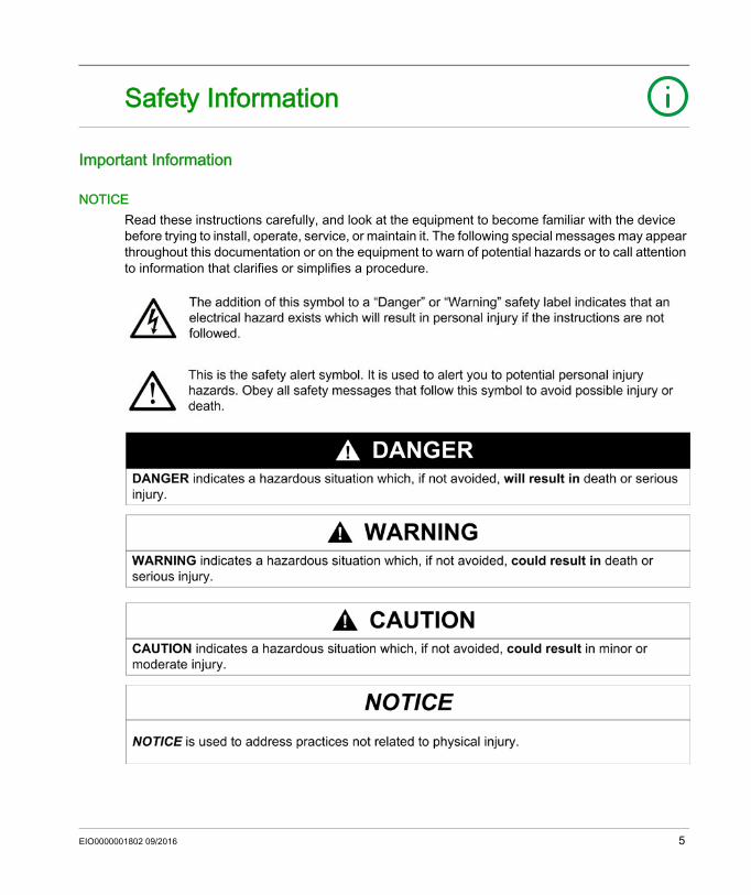
NOTICERead these instructions carefully, and look at the equipment to become familiar with the device before trying to install, operate, service, or maintain it. The following special messages may appear throughout this documentation or on the equipment to warn of potential hazards or to call attention to information that clarifies or simplifies a procedure.
EIO0000001802 09/2016 5
PLEASE NOTEElectrical equipment should be installed, operated, serviced, and maintained only by qualified personnel. No responsibility is assumed by Schneider Electric for any consequences arising out of the use of this material.A qualified person is one who has skills and knowledge related to the construction and operation of electrical equipment and its installation, and has received safety training to recognize and avoid the hazards involved.
6 EIO0000001802 09/2016
About the Book
At a Glance
Document ScopeThis document describes the configuration of the TM4 expansion modules for SoMachine. For further information, refer to the separate documents provided in the SoMachine online help.
Validity NoteThis document has been updated for the release of SoMachine V4.2.
Related Documents
Title of Documentation Reference NumberSoMachine Programming Guide EIO0000000067 (ENG)
EIO0000000069 (FRE)EIO0000000068 (GER)EIO0000000071 (SPA)EIO0000000070 (ITA)EIO0000000072 (CHS)
Modicon M241 Logic Controller - Programming Guide EIO0000001432 (ENG)EIO0000001433 (FRA)EIO0000001434 (GER)EIO0000001435 (SPA)EIO0000001436 (ITA)EIO0000001437 (CHS)
Modicon M251 Logic Controller - Programming Guide EIO0000001462 (ENG)EIO0000001463 (FRA)EIO0000001464 (GER)EIO0000001465 (SPA)EIO0000001466 (ITA)EIO0000001467 (CHS)
EIO0000001802 09/2016 7
You can download these technical publications and other technical information from our website at http://download.schneider-electric.com
Product Related Information
1 For additional information, refer to NEMA ICS 1.1 (latest edition), "Safety Guidelines for the Application, Installation, and Maintenance of Solid State Control" and to NEMA ICS 7.1 (latest edition), "Safety Standards for Construction and Guide for Selection, Installation and Operation of Adjustable-Speed Drive Systems" or their equivalent governing your particular location.
TM4 Expansion Modules - Hardware Guide EIO0000001796 (ENG)EIO0000001797 (FRA)EIO0000001798 (GER)EIO0000001799 (SPA)EIO0000001800 (ITA)EIO0000001801 (CHS)
TM4 Expansion Modules - Instruction Sheet EAV47886
Title of Documentation Reference Number
WARNINGLOSS OF CONTROL The designer of any control scheme must consider the potential failure modes of control paths
and, for certain critical control functions, provide a means to achieve a safe state during and after a path failure. Examples of critical control functions are emergency stop and overtravel stop, power outage and restart.
Separate or redundant control paths must be provided for critical control functions. System control paths may include communication links. Consideration must be given to the
implications of unanticipated transmission delays or failures of the link. Observe all accident prevention regulations and local safety guidelines.1 Each implementation of this equipment must be individually and thoroughly tested for proper
operation before being placed into service.Failure to follow these instructions can result in death, serious injury, or equipment damage.
WARNINGUNINTENDED EQUIPMENT OPERATION Only use software approved by Schneider Electric for use with this equipment. Update your application program every time you change the physical hardware configuration.Failure to follow these instructions can result in death, serious injury, or equipment damage.
8 EIO0000001802 09/2016
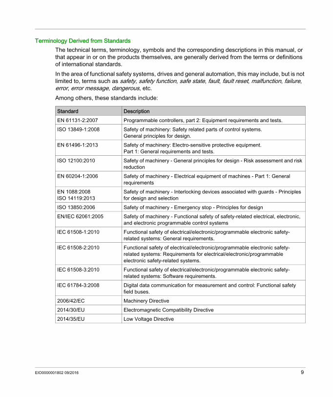
Terminology Derived from StandardsThe technical terms, terminology, symbols and the corresponding descriptions in this manual, or that appear in or on the products themselves, are generally derived from the terms or definitions of international standards.In the area of functional safety systems, drives and general automation, this may include, but is not limited to, terms such as safety, safety function, safe state, fault, fault reset, malfunction, failure, error, error message, dangerous, etc.Among others, these standards include:
Standard DescriptionEN 61131-2:2007 Programmable controllers, part 2: Equipment requirements and tests.ISO 13849-1:2008 Safety of machinery: Safety related parts of control systems.
General principles for design.EN 61496-1:2013 Safety of machinery: Electro-sensitive protective equipment.
Part 1: General requirements and tests.ISO 12100:2010 Safety of machinery - General principles for design - Risk assessment and risk
reductionEN 60204-1:2006 Safety of machinery - Electrical equipment of machines - Part 1: General
requirementsEN 1088:2008ISO 14119:2013
Safety of machinery - Interlocking devices associated with guards - Principles for design and selection
ISO 13850:2006 Safety of machinery - Emergency stop - Principles for designEN/IEC 62061:2005 Safety of machinery - Functional safety of safety-related electrical, electronic,
and electronic programmable control systemsIEC 61508-1:2010 Functional safety of electrical/electronic/programmable electronic safety-
related systems: General requirements.IEC 61508-2:2010 Functional safety of electrical/electronic/programmable electronic safety-
related systems: Requirements for electrical/electronic/programmable electronic safety-related systems.
IEC 61508-3:2010 Functional safety of electrical/electronic/programmable electronic safety-related systems: Software requirements.
IEC 61784-3:2008 Digital data communication for measurement and control: Functional safety field buses.
2006/42/EC Machinery Directive2014/30/EU Electromagnetic Compatibility Directive2014/35/EU Low Voltage Directive
EIO0000001802 09/2016 9
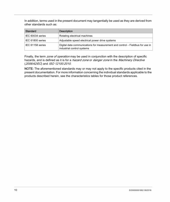
In addition, terms used in the present document may tangentially be used as they are derived from other standards such as:
Finally, the term zone of operation may be used in conjunction with the description of specific hazards, and is defined as it is for a hazard zone or danger zone in the Machinery Directive (2006/42/EC) and ISO 12100:2010.NOTE: The aforementioned standards may or may not apply to the specific products cited in the present documentation. For more information concerning the individual standards applicable to the products described herein, see the characteristics tables for those product references.
Standard DescriptionIEC 60034 series Rotating electrical machinesIEC 61800 series Adjustable speed electrical power drive systemsIEC 61158 series Digital data communications for measurement and control – Fieldbus for use in
industrial control systems
10 EIO0000001802 09/2016
Modicon TM4General DescriptionEIO0000001802 09/2016
General Description
Chapter 1General Description
IntroductionThis chapter provides a general description of TM4 expansion modules.
What Is in This Chapter?This chapter contains the following topics:
Topic PageGeneral Description 12TM4 Expansion Modules Compatibility 13Adding a TM4 Expansion Module 15Connecting the Controller to a PC 16
EIO0000001802 09/2016 11
General Description
General Description
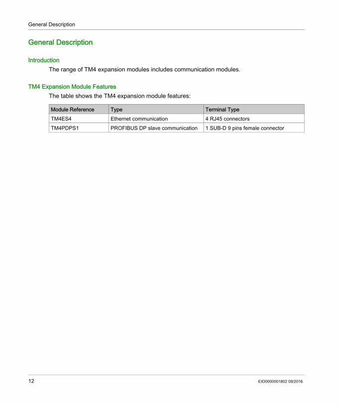
IntroductionThe range of TM4 expansion modules includes communication modules.
TM4 Expansion Module FeaturesThe table shows the TM4 expansion module features:
Module Reference Type Terminal TypeTM4ES4 Ethernet communication 4 RJ45 connectors TM4PDPS1 PROFIBUS DP slave communication 1 SUB-D 9 pins female connector
12 EIO0000001802 09/2016
General Description
TM4 Expansion Modules Compatibility
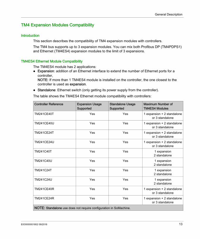
IntroductionThis section describes the compatibility of TM4 expansion modules with controllers.The TM4 bus supports up to 3 expansion modules. You can mix both Profibus DP (TM4PDPS1) and Ethernet (TM4ES4) expansion modules to the limit of 3 expansions.
TM4ES4 Ethernet Module CompatibilityThe TM4ES4 module has 2 applications: Expansion: addition of an Ethernet interface to extend the number of Ethernet ports for a
controller,NOTE: If more than 1 TM4ES4 module is installed on the controller, the one closest to the controller is used as expansion.
Standalone: Ethernet switch (only getting its power supply from the controller).The table shows the TM4ES4 Ethernet module compatibility with controllers:
Controller Reference Expansion Usage Supported
Standalone Usage Supported
Maximum Number of TM4ES4 Modules
TM241CE40T Yes Yes 1 expansion + 2 standaloneor 3 standalone
TM241CE40U Yes Yes 1 expansion + 2 standaloneor 3 standalone
TM241CE24T Yes Yes 1 expansion + 2 standaloneor 3 standalone
TM241CE24U Yes Yes 1 expansion + 2 standaloneor 3 standalone
TM241C40T Yes Yes 1 expansion2 standalone
TM241C40U Yes Yes 1 expansion2 standalone
TM241C24T Yes Yes 1 expansion2 standalone
TM241C24U Yes Yes 1 expansion2 standalone
TM241CE40R Yes Yes 1 expansion + 2 standaloneor 3 standalone
TM241CE24R Yes Yes 1 expansion + 2 standaloneor 3 standalone
NOTE: Standalone use does not require configuration in SoMachine.
EIO0000001802 09/2016 13
General Description
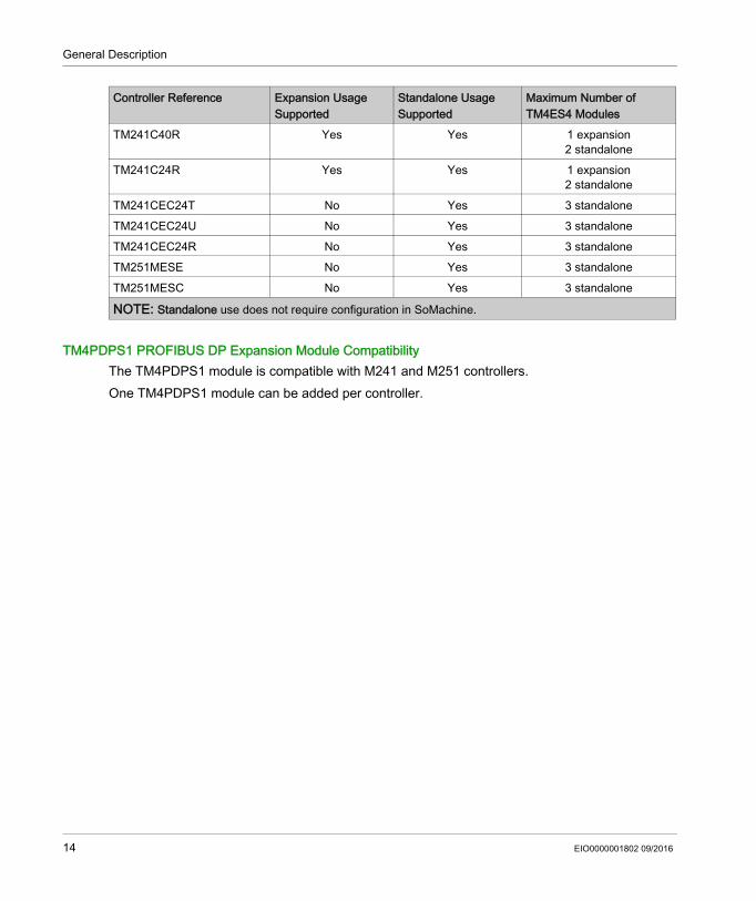
TM4PDPS1 PROFIBUS DP Expansion Module CompatibilityThe TM4PDPS1 module is compatible with M241 and M251 controllers.One TM4PDPS1 module can be added per controller.
TM241C40R Yes Yes 1 expansion2 standalone
TM241C24R Yes Yes 1 expansion2 standalone
TM241CEC24T No Yes 3 standaloneTM241CEC24U No Yes 3 standaloneTM241CEC24R No Yes 3 standaloneTM251MESE No Yes 3 standaloneTM251MESC No Yes 3 standalone
Controller Reference Expansion Usage Supported
Standalone Usage Supported
Maximum Number of TM4ES4 Modules
NOTE: Standalone use does not require configuration in SoMachine.
14 EIO0000001802 09/2016
General Description
Adding a TM4 Expansion Module
Adding a TM4 Expansion ModuleTo add an expansion module to your controller, select the expansion module in the Hardware Catalog, drag it to the Devices tree, and drop it on the COM_Bus node.For more information on adding a device to your project, refer to:• Using the Drag-and-drop Method (see SoMachine, Programming Guide)• Using the Contextual Menu or Plus Button (see SoMachine, Programming Guide)
Expansion Module ConfigurationTo configure your TM4 Expansion Module, double click the expansion module node in the Devices tree to display the configuration tabs. The following chapters detail the configuration parameters.NOTE: You do not configure the TM4ES4 when using it as a standalone switch in SoMachine. As such, the TM4ES4 module does not appear in the Devices tree.
EIO0000001802 09/2016 15
General Description
Connecting the Controller to a PC
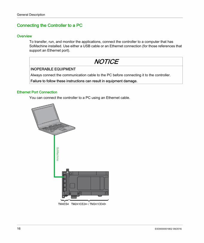
OverviewTo transfer, run, and monitor the applications, connect the controller to a computer that has SoMachine installed. Use either a USB cable or an Ethernet connection (for those references that support an Ethernet port).
Ethernet Port ConnectionYou can connect the controller to a PC using an Ethernet cable.
NOTICEINOPERABLE EQUIPMENTAlways connect the communication cable to the PC before connecting it to the controller.Failure to follow these instructions can result in equipment damage.
16 EIO0000001802 09/2016
General Description
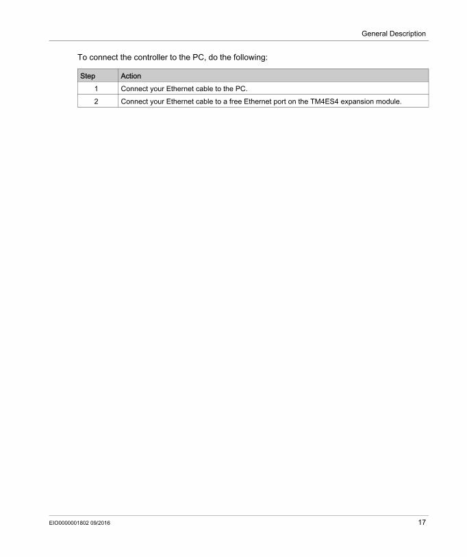
To connect the controller to the PC, do the following:
Step Action1 Connect your Ethernet cable to the PC.2 Connect your Ethernet cable to a free Ethernet port on the TM4ES4 expansion module.
EIO0000001802 09/2016 17

General Description
18 EIO0000001802 09/2016
Modicon TM4TM4ES4 Ethernet ModuleEIO0000001802 09/2016
TM4ES4 Ethernet Module
Chapter 2TM4ES4 Ethernet Module
IntroductionThis chapter describes the configuration of the TM4ES4 Ethernet module when it is used as Expansion.In Standalone use, the module does not require configuration in SoMachine, and therefore the information in this chapter is not applicable.Refer to TM4ES4 Ethernet Module Compatibility (see page 13) to know the application type according to the controller reference compatibility.
What Is in This Chapter?This chapter contains the following sections:
Section Topic Page2.1 Ethernet Services 202.2 Firewall Configuration 68
EIO0000001802 09/2016 19
TM4ES4 Ethernet Module
Ethernet Services
Section 2.1Ethernet Services
What Is in This Section?This section contains the following topics:
Topic PagePresentation 21IP Address Configuration 23Modbus TCP Server/Client 28Web Server 30FTP Server 42SNMP 44M241 Logic Controller as a Target Device on EtherNet/IP 45M241 Logic Controller as a Slave Device on Modbus TCP 63
20 EIO0000001802 09/2016
TM4ES4 Ethernet Module
Presentation
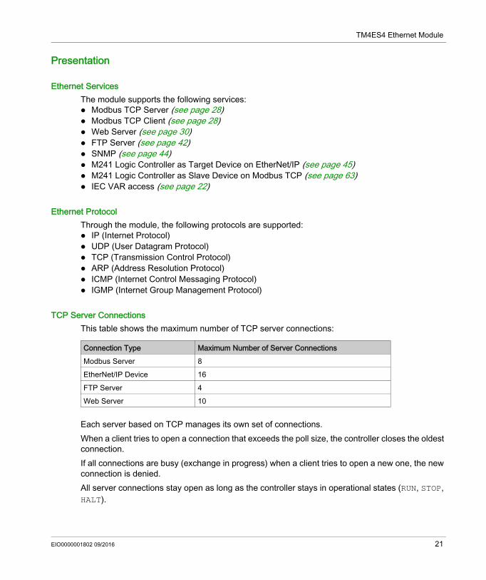
Ethernet ServicesThe module supports the following services: Modbus TCP Server (see page 28) Modbus TCP Client (see page 28) Web Server (see page 30) FTP Server (see page 42) SNMP (see page 44) M241 Logic Controller as Target Device on EtherNet/IP (see page 45) M241 Logic Controller as Slave Device on Modbus TCP (see page 63) IEC VAR access (see page 22)
Ethernet ProtocolThrough the module, the following protocols are supported: IP (Internet Protocol) UDP (User Datagram Protocol) TCP (Transmission Control Protocol) ARP (Address Resolution Protocol) ICMP (Internet Control Messaging Protocol) IGMP (Internet Group Management Protocol)
TCP Server ConnectionsThis table shows the maximum number of TCP server connections:
Each server based on TCP manages its own set of connections.When a client tries to open a connection that exceeds the poll size, the controller closes the oldest connection.If all connections are busy (exchange in progress) when a client tries to open a new one, the new connection is denied.All server connections stay open as long as the controller stays in operational states (RUN, STOP, HALT).
Connection Type Maximum Number of Server ConnectionsModbus Server 8EtherNet/IP Device 16FTP Server 4Web Server 10
EIO0000001802 09/2016 21
TM4ES4 Ethernet Module
All server connections are closed when leaving or entering operational states (RUN, STOP, HALT), except in case of power outage (because the controller does not have time to close the connections).For more information about the operational states, refer to the controller state diagram (see Modicon M241 Logic Controller, Programming Guide).
Services AvailableWith an Ethernet communication, the IEC VAR ACCESS service is supported by the controller. With the IEC VAR ACCESS service, variables can be exchanged between the controller and an HMI.The NetWork variables service is also supported by the controller. With the NetWork variables service, data can be exchanged between controllers.NOTE: For more information, refer to the SoMachine Programming Guide.
22 EIO0000001802 09/2016
TM4ES4 Ethernet Module
IP Address Configuration
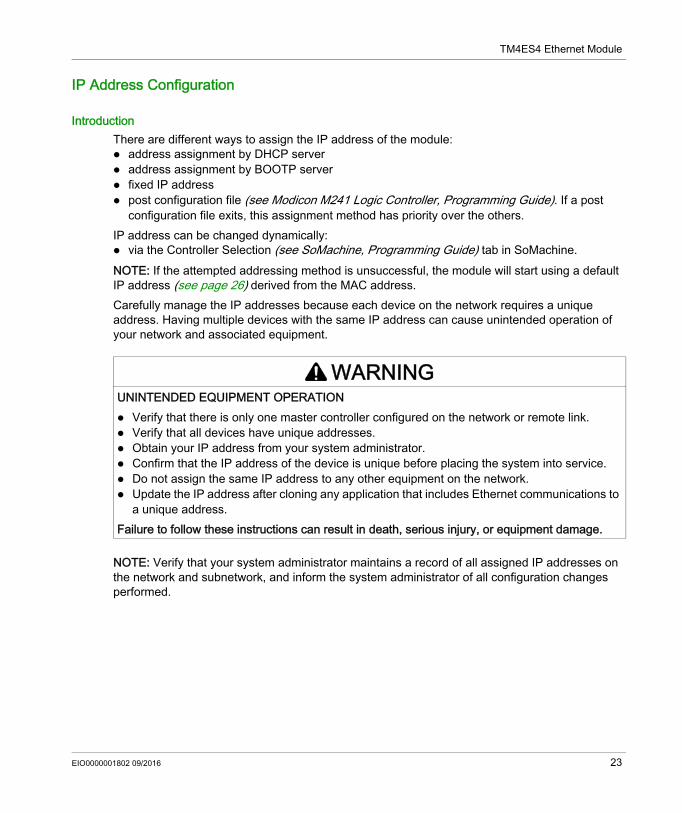
IntroductionThere are different ways to assign the IP address of the module: address assignment by DHCP server address assignment by BOOTP server fixed IP address post configuration file (see Modicon M241 Logic Controller, Programming Guide). If a post
configuration file exits, this assignment method has priority over the others.IP address can be changed dynamically: via the Controller Selection (see SoMachine, Programming Guide) tab in SoMachine.NOTE: If the attempted addressing method is unsuccessful, the module will start using a default IP address (see page 26) derived from the MAC address.Carefully manage the IP addresses because each device on the network requires a unique address. Having multiple devices with the same IP address can cause unintended operation of your network and associated equipment.
NOTE: Verify that your system administrator maintains a record of all assigned IP addresses on the network and subnetwork, and inform the system administrator of all configuration changes performed.
WARNINGUNINTENDED EQUIPMENT OPERATION Verify that there is only one master controller configured on the network or remote link. Verify that all devices have unique addresses. Obtain your IP address from your system administrator. Confirm that the IP address of the device is unique before placing the system into service. Do not assign the same IP address to any other equipment on the network. Update the IP address after cloning any application that includes Ethernet communications to
a unique address.Failure to follow these instructions can result in death, serious injury, or equipment damage.
EIO0000001802 09/2016 23
TM4ES4 Ethernet Module
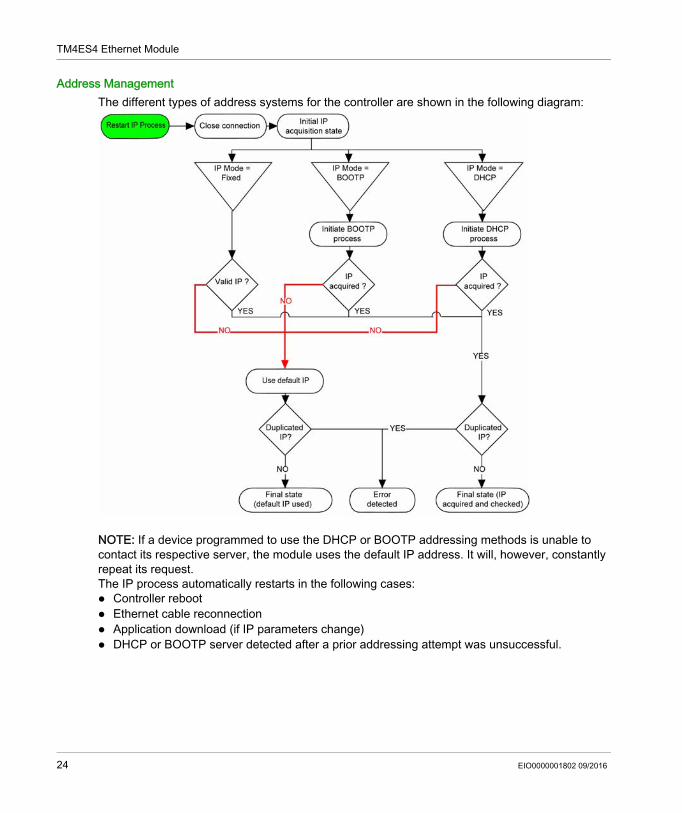
Address ManagementThe different types of address systems for the controller are shown in the following diagram:
NOTE: If a device programmed to use the DHCP or BOOTP addressing methods is unable to contact its respective server, the module uses the default IP address. It will, however, constantly repeat its request.The IP process automatically restarts in the following cases: Controller reboot Ethernet cable reconnection Application download (if IP parameters change) DHCP or BOOTP server detected after a prior addressing attempt was unsuccessful.
24 EIO0000001802 09/2016
TM4ES4 Ethernet Module
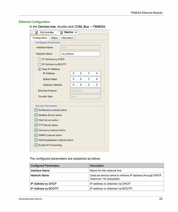
Ethernet ConfigurationIn the Devices tree, double-click COM_Bus → TM4ES4:
The configured parameters are explained as below:
Configured Parameters DescriptionInterface Name Name for the network linkNetwork Name Used as device name to retrieve IP address through DHCP,
maximum 16 charactersIP Address by DHCP IP address is obtained via DHCP.IP Address by BOOTP IP address is obtained via BOOTP.
EIO0000001802 09/2016 25
TM4ES4 Ethernet Module
Default IP AddressThe IP address by default is 11.11.x.x.The last 2 fields in the default IP address are composed of the decimal equivalent of the last 2 hexadecimal bytes of the MAC address of the module.The MAC address of the module can be retrieved at the bottom of the front face of the module.The default subnet mask is 255.0.0.0.NOTE: A MAC address is always written in hexadecimal format, and an IP address in decimal format. You must convert the MAC address to decimal format.Example: If the MAC address is 00.80.F4.01.80.F2, the default IP address is 11.11.128.242.NOTE: To take into account the new IP address after the download of a project, reboot the controller by doing a power cycle.
Subnet MaskThe subnet mask is used to address several physical networks with a single network address. The mask is used to separate the subnetwork and the device address in the host ID. The subnet address is obtained by retaining the bits of the IP address that correspond to the positions of the mask containing 1, and replacing the others with 0.Conversely, the subnet address of the host device is obtained by retaining the bits of the IP address that correspond to the positions of the mask containing 0, and replacing the others with 1.Example of a subnet address:
NOTE: The device does not communicate on its subnetwork when there is no gateway.
GatewayThe gateway allows a message to be routed to a device which is not on the current network.If there is no gateway, the gateway address is 0.0.0.0.
Fixed IP Address IP address, subnet mask and gateway address are defined by the user.
Ethernet Protocol Protocol type used (Ethernet 2)Transfer Rate Transfer rate and direction on the bus are automatically
configured.Security Parameters Security Parameters (see page 27)
Configured Parameters Description
IP address 192 (11000000) 1 (00000001) 17 (00010001) 11 (00001011)Subnet mask 255 (11111111) 255 (11111111) 240 (11110000) 0 (00000000)Subnet address 192 (11000000) 1 (00000001) 16 (00010000) 0 (00000000)
26 EIO0000001802 09/2016
TM4ES4 Ethernet Module
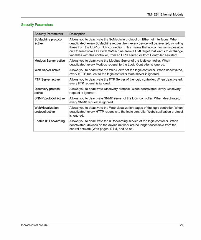
Security Parameters
Security Parameters DescriptionSoMachine protocol active
Allows you to deactivate the SoMachine protocol on Ethernet interfaces. When deactivated, every SoMachine request from every device will be rejected, including those from the UDP or TCP connection. This means that no connection is possible on Ethernet from a PC with SoMachine, from a HMI target that wants to exchange variables with this controller, from an OPC server, or from Controller Assistant.
Modbus Server active Allows you to deactivate the Modbus Server of the logic controller. When deactivated, every Modbus request to the Logic Controller is ignored.
Web Server active Allows you to deactivate the Web Server of the logic controller. When deactivated, every HTTP request to the logic controller Web server is ignored.
FTP Server active Allows you to deactivate the FTP Server of the logic controller. When deactivated, every FTP request is ignored.
Discovery protocol active
Allows you to deactivate Discovery protocol. When deactivated, every Discovery request is ignored.
SNMP protocol active Allows you to deactivate SNMP server of the logic controller. When deactivated, every SNMP request is ignored.
WebVisualization protocol active
Allows you to deactivate the Web visualization pages of the logic controller. When deactivated, every HTTP requests to the logic controller Webvisualisation protocol is ignored.
Enable IP Forwarding Allows you to deactivate the IP forwarding service of the logic controller. When deactivated, devices on the device network are no longer accessible from the control network (Web pages, DTM, and so on).
EIO0000001802 09/2016 27
TM4ES4 Ethernet Module
Modbus TCP Server/Client
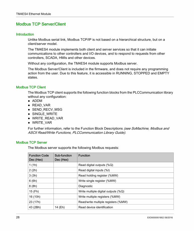
IntroductionUnlike Modbus serial link, Modbus TCP/IP is not based on a hierarchical structure, but on a client/server model.The TM4ES4 module implements both client and server services so that it can initiate communications to other controllers and I/O devices, and to respond to requests from other controllers, SCADA, HMIs and other devices.Without any configuration, the TM4ES4 module supports Modbus server.The Modbus Server/Client is included in the firmware, and does not require any programming action from the user. Due to this feature, it is accessible in RUNNING, STOPPED and EMPTY states.
Modbus TCP ClientThe Modbus TCP client supports the following function blocks from the PLCCommunication library without any configuration: ADDM READ_VAR SEND_RECV_MSG SINGLE_WRITE WRITE_READ_VAR WRITE_VARFor further information, refer to the Function Block Descriptions (see SoMachine, Modbus and ASCII Read/Write Functions, PLCCommunication Library Guide).
Modbus TCP ServerThe Modbus server supports the following Modbus requests:
Function CodeDec (Hex)
Sub-functionDec (Hex)
Function
1 (1h) Read digital outputs (%Q)2 (2h) Read digital inputs (%I)3 (3h) Read holding register (%MW)6 (6h) Write single register (%MW)8 (8h) Diagnostic15 (Fh) Write multiple digital outputs (%Q)16 (10h) Write multiple registers (%MW)23 (17h) Read/write multiple registers (%MW)43 (2Bh) 14 (Eh) Read device identification
28 EIO0000001802 09/2016
TM4ES4 Ethernet Module
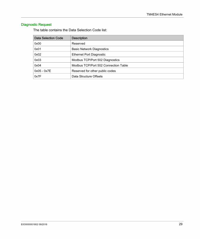
Diagnostic RequestThe table contains the Data Selection Code list:
Data Selection Code Description0x00 Reserved0x01 Basic Network Diagnostics0x02 Ethernet Port Diagnostic0x03 Modbus TCP/Port 502 Diagnostics0x04 Modbus TCP/Port 502 Connection Table 0x05 - 0x7E Reserved for other public codes0x7F Data Structure Offsets
EIO0000001802 09/2016 29
TM4ES4 Ethernet Module
Web Server
IntroductionThe controller provides as a standard equipment an embedded Web server with a predefined factory built-in website. You can use the pages of the website for module setup and control as well as application diagnostics and monitoring. These pages are ready to use with a Web browser. No configuration or programming is required.The Web server can be accessed by the web browsers listed below: Google Chrome (version 30.0 or higher) Mozilla Firefox (version 1.5 or higher)The Web server is limited to 10 TCP connections.NOTE: The Web server can be disabled by unchecking the Web Server active parameter in the Ethernet Configuration tab. The Web server is a tool for reading and writing data, and controlling the state of the controller, with full access to all data in your application. However, if there are security concerns over these functions, you must at a minimum assign a secure password to the Web Server or disable the Web server to prevent unauthorized access to the application. By enabling the Web server, you enable these functions.The Web server allows you to monitor a controller and its application remotely, to perform various maintenance activities including modifications to data and configuration parameters, and change the state of the controller. Care must be taken to ensure that the immediate physical environment of the machine and process is in a state that will not present safety risks to people or property before exercising control remotely.
WARNINGUNINTENDED EQUIPMENT OPERATION Configure and install the RUN/STOP input for the application, if available for your particular
controller, so that local control over the starting or stopping of the controller can be maintained regardless of the remote commands sent to the controller.
Define a secure password for the Web Server, and do not allow unauthorized or otherwise unqualified personnel to use this feature.
Ensure that there is a local, competent, and qualified observer present when operating on the controller from a remote location.
You must have a complete understanding of the application and the machine/process it is controlling before attempting to adjust data, stopping an application that is operating, or starting the controller remotely.
Take the precautions necessary to assure that you are operating on the intended controller by having clear, identifying documentation within the controller application and its remote connection.
Failure to follow these instructions can result in death, serious injury, or equipment damage.
30 EIO0000001802 09/2016
TM4ES4 Ethernet Module
NOTE: The Web server must only be used by authorized and qualified personnel. A qualified person is one who has the skills and knowledge related to the construction and operation of the machine and the process controlled by the application and its installation, and has received safety training to recognize and avoid the hazards involved. No responsibility is assumed by Schneider Electric for any consequences arising out of the use of this feature.
Web Server AccessAccess to the Web server is controlled by User Rights when they are enabled in the controller. For more information, refer to Users and Groups Tab Description.If User Rights are not enabled in the controller, you are prompted for a user name and password unique to the FTP/Web server. The default user name is USER and the default password is also USER.NOTE: You cannot modify the default user name and password. To secure the FTP/Web server functions, you must do so with Users and Groups.
In order to change the password, go to Users and Groups tab of the device editor. For more information, refer to the SoMachine Programming Guide.NOTE: The only way to gain access to a controller that has user access-rights enabled and for which you do not have the password(s) is by performing an Update Firmware operation. This clearing of User Rights can only be accomplished by using a SD card or USB key (depending on the support of your particular controller) to update the controller firmware. In addition, you may clear the User Rights in the controller by running a script (for more information, refer to SoMachine Programming Guide). This effectively removes the existing application from the controller memory, but restores the ability to access the controller.
WARNINGUNAUTHORIZED DATA ACCESS Secure access to the FTP/Web server using User Rights. If you do not enable User Rights, disable the FTP/Web server to prevent any unwanted or
unauthorized access to data in your application.Failure to follow these instructions can result in death, serious injury, or equipment damage.
EIO0000001802 09/2016 31
TM4ES4 Ethernet Module
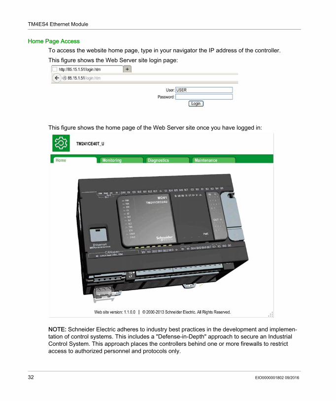
Home Page AccessTo access the website home page, type in your navigator the IP address of the controller.This figure shows the Web Server site login page:
This figure shows the home page of the Web Server site once you have logged in:
NOTE: Schneider Electric adheres to industry best practices in the development and implemen-tation of control systems. This includes a "Defense-in-Depth" approach to secure an Industrial Control System. This approach places the controllers behind one or more firewalls to restrict access to authorized personnel and protocols only.
32 EIO0000001802 09/2016
TM4ES4 Ethernet Module
WARNINGUNAUTHENTICATED ACCESS AND SUBSEQUENT UNAUTHORIZED MACHINE OPERATION Evaluate whether your environment or your machines are connected to your critical
infrastructure and, if so, take appropriate steps in terms of prevention, based on Defense-in-Depth, before connecting the automation system to any network.
Limit the number of devices connected to a network to the minimum necessary. Isolate your industrial network from other networks inside your company. Protect any network against unintended access by using firewalls, VPN, or other, proven
security measures. Monitor activities within your systems. Prevent subject devices from direct access or direct link by unauthorized parties or unauthen-
ticated actions. Prepare a recovery plan including backup of your system and process information.Failure to follow these instructions can result in death, serious injury, or equipment damage.
EIO0000001802 09/2016 33
TM4ES4 Ethernet Module
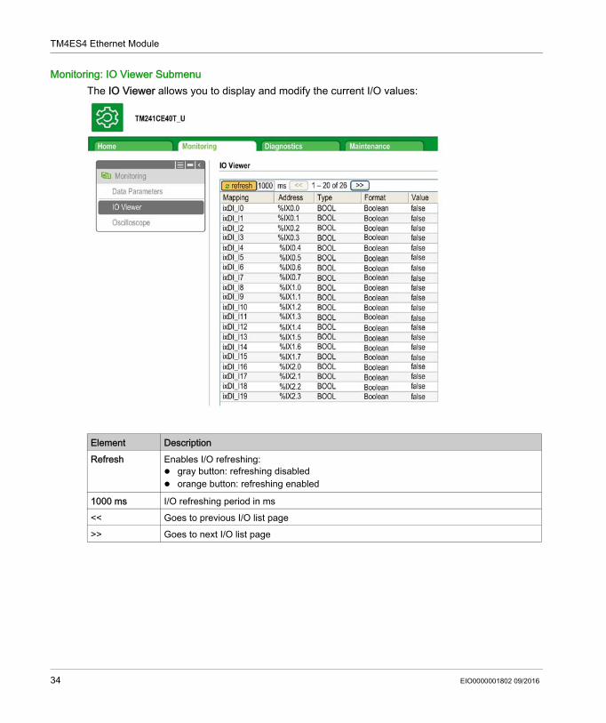
Monitoring: IO Viewer SubmenuThe IO Viewer allows you to display and modify the current I/O values:
Element DescriptionRefresh Enables I/O refreshing:
gray button: refreshing disabled orange button: refreshing enabled
1000 ms I/O refreshing period in ms<< Goes to previous I/O list page>> Goes to next I/O list page
34 EIO0000001802 09/2016
TM4ES4 Ethernet Module
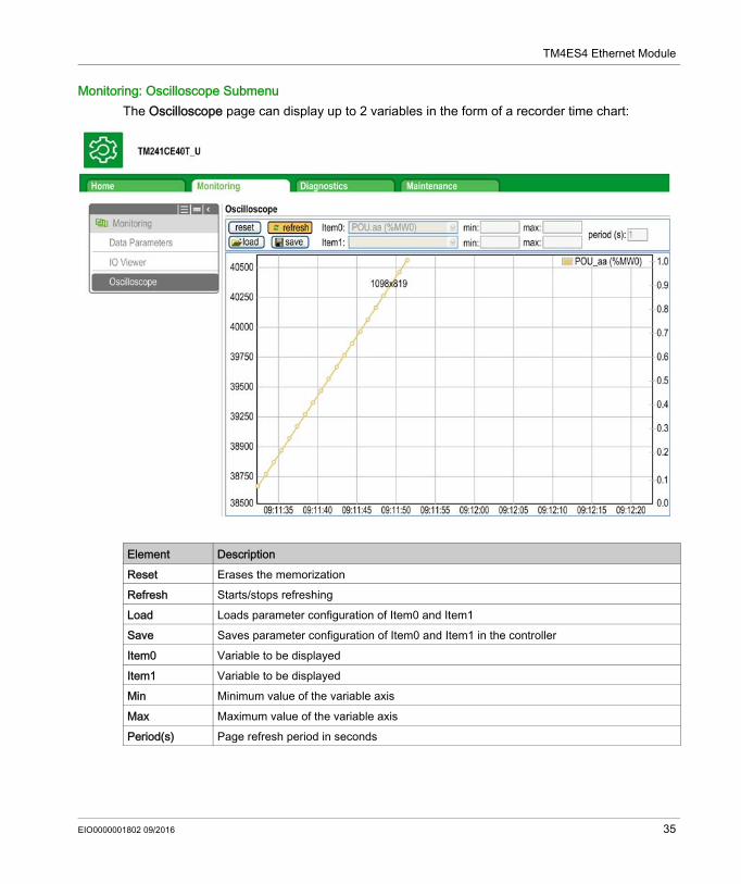
Monitoring: Oscilloscope SubmenuThe Oscilloscope page can display up to 2 variables in the form of a recorder time chart:
Element DescriptionReset Erases the memorizationRefresh Starts/stops refreshingLoad Loads parameter configuration of Item0 and Item1Save Saves parameter configuration of Item0 and Item1 in the controllerItem0 Variable to be displayedItem1 Variable to be displayedMin Minimum value of the variable axisMax Maximum value of the variable axisPeriod(s) Page refresh period in seconds
EIO0000001802 09/2016 35
TM4ES4 Ethernet Module
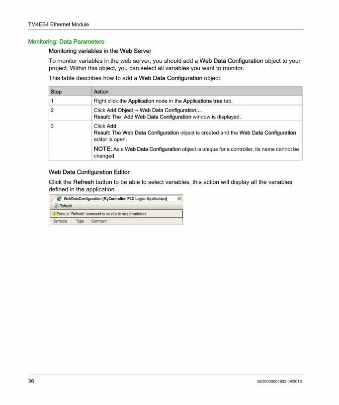
Monitoring: Data ParametersMonitoring variables in the Web ServerTo monitor variables in the web server, you should add a Web Data Configuration object to your project. Within this object, you can select all variables you want to monitor.This table describes how to add a Web Data Configuration object:
Web Data Configuration EditorClick the Refresh button to be able to select variables, this action will display all the variables defined in the application.
Step Action1 Right click the Application node in the Applications tree tab.2 Click Add Object → Web Data Configuration....
Result: The Add Web Data Configuration window is displayed.3 Click Add.
Result: The Web Data Configuration object is created and the Web Data Configuration editor is open.
NOTE: As a Web Data Configuration object is unique for a controller, its name cannot be changed.
36 EIO0000001802 09/2016
TM4ES4 Ethernet Module
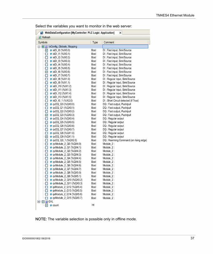
Select the variables you want to monitor in the web server:
NOTE: The variable selection is possible only in offline mode.
EIO0000001802 09/2016 37
TM4ES4 Ethernet Module
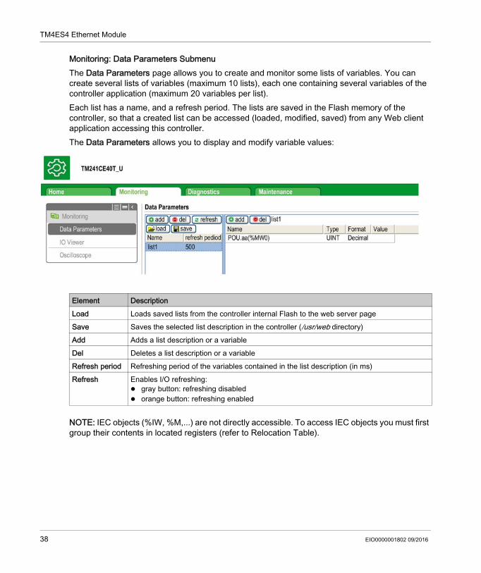
Monitoring: Data Parameters SubmenuThe Data Parameters page allows you to create and monitor some lists of variables. You can create several lists of variables (maximum 10 lists), each one containing several variables of the controller application (maximum 20 variables per list).Each list has a name, and a refresh period. The lists are saved in the Flash memory of the controller, so that a created list can be accessed (loaded, modified, saved) from any Web client application accessing this controller.The Data Parameters allows you to display and modify variable values:
NOTE: IEC objects (%IW, %M,...) are not directly accessible. To access IEC objects you must first group their contents in located registers (refer to Relocation Table).
Element DescriptionLoad Loads saved lists from the controller internal Flash to the web server pageSave Saves the selected list description in the controller (/usr/web directory)Add Adds a list description or a variableDel Deletes a list description or a variableRefresh period Refreshing period of the variables contained in the list description (in ms)Refresh Enables I/O refreshing:
gray button: refreshing disabled orange button: refreshing enabled
38 EIO0000001802 09/2016
TM4ES4 Ethernet Module
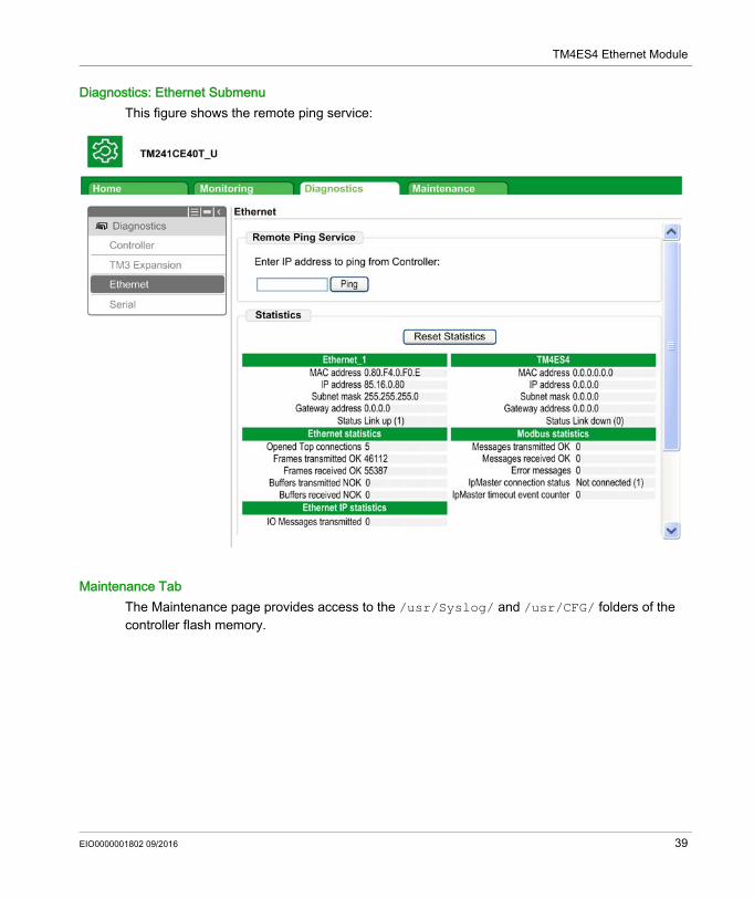
Diagnostics: Ethernet SubmenuThis figure shows the remote ping service:
Maintenance TabThe Maintenance page provides access to the /usr/Syslog/ and /usr/CFG/ folders of the controller flash memory.
EIO0000001802 09/2016 39
TM4ES4 Ethernet Module
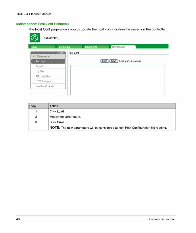
Maintenance: Post Conf SubmenuThe Post Conf page allows you to update the post configuration file saved on the controller:
Step Action1 Click Load.2 Modify the parameters.3 Click Save.
NOTE: The new parameters will be considered at next Post Configuration file reading.
40 EIO0000001802 09/2016
TM4ES4 Ethernet Module
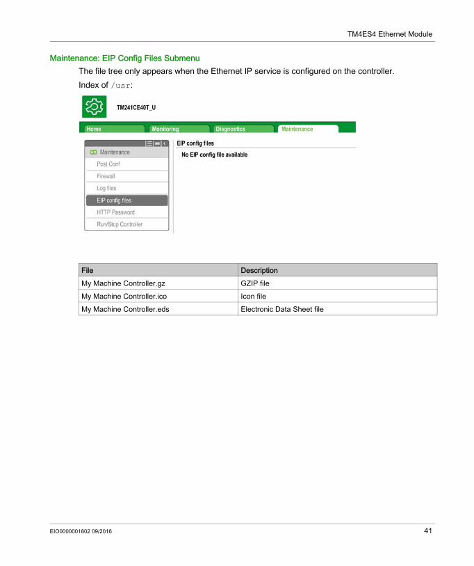
Maintenance: EIP Config Files SubmenuThe file tree only appears when the Ethernet IP service is configured on the controller.Index of /usr:
File DescriptionMy Machine Controller.gz GZIP fileMy Machine Controller.ico Icon fileMy Machine Controller.eds Electronic Data Sheet file
EIO0000001802 09/2016 41
TM4ES4 Ethernet Module
FTP Server
IntroductionAny FTP client installed on a computer that is connected to the controller (Ethernet port), without SoMachine installed, can be used to transfer files to and from the data storage area of the controller.NOTE: Schneider Electric adheres to industry best practices in the development and implemen-tation of control systems. This includes a "Defense-in-Depth" approach to secure an Industrial Control System. This approach places the controllers behind one or more firewalls to restrict access to authorized personnel and protocols only.
NOTE: Make use of the security-related commands which provide a way to add, edit, and remove a user in the online user management of the target device where you are currently logged in.The FTP server is available even if the controller is empty (no user application and no User Rights are enabled).
WARNINGUNAUTHENTICATED ACCESS AND SUBSEQUENT UNAUTHORIZED MACHINE OPERATION Evaluate whether your environment or your machines are connected to your critical
infrastructure and, if so, take appropriate steps in terms of prevention, based on Defense-in-Depth, before connecting the automation system to any network.
Limit the number of devices connected to a network to the minimum necessary. Isolate your industrial network from other networks inside your company. Protect any network against unintended access by using firewalls, VPN, or other, proven
security measures. Monitor activities within your systems. Prevent subject devices from direct access or direct link by unauthorized parties or unauthen-
ticated actions. Prepare a recovery plan including backup of your system and process information.Failure to follow these instructions can result in death, serious injury, or equipment damage.
42 EIO0000001802 09/2016
TM4ES4 Ethernet Module
FTP AccessAccess to the FTP server is controlled by User Rights when they are enabled in the controller. For more information, refer to Users and Groups Tab Description.If User Rights are not enabled in the controller, you are prompted for a user name and password unique to the FTP/Web server. The default user name is USER and the default password is also USER.NOTE: You cannot modify the default user name and password. To secure the FTP/Web server functions, you must do so with Users and Groups.
In order to change the password, go to Users and Groups tab of the device editor. For more information, refer to the SoMachine Programming Guide.NOTE: The only way to gain access to a controller that has user access-rights enabled and for which you do not have the password(s) is by performing an Update Firmware operation. This clearing of User Rights can only be accomplished by using a SD card or USB key (depending on the support of your particular controller) to update the controller firmware. In addition, you may clear the User Rights in the controller by running a script (for more information, refer to SoMachine Programming Guide). This effectively removes the existing application from the controller memory, but restores the ability to access the controller.
Files AccessSee File Organization.
WARNINGUNAUTHORIZED DATA ACCESS Secure access to the FTP/Web server using User Rights. If you do not enable User Rights, disable the FTP/Web server to prevent any unwanted or
unauthorized access to data in your application.Failure to follow these instructions can result in death, serious injury, or equipment damage.
EIO0000001802 09/2016 43
TM4ES4 Ethernet Module
SNMP
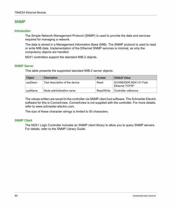
IntroductionThe Simple Network Management Protocol (SNMP) is used to provide the data and services required for managing a network.The data is stored in a Management Information Base (MIB). The SNMP protocol is used to read or write MIB data. Implementation of the Ethernet SNMP services is minimal, as only the compulsory objects are handled.M241 controllers support the standard MIB-2 objects.
SNMP ServerThis table presents the supported standard MIB-2 server objects:
The values written are saved to the controller via SNMP client tool software. The Schneider Electric software for this is ConneXview. ConneXview is not supplied with the controller. For more details, refer to www.schneider-electric.com.The size of these character strings is limited to 50 characters.
SNMP ClientThe M251 Logic Controller includes an SNMP client library to allow you to query SNMP servers. For details, refer to the SNMP Library Guide.
Object Description Access Default ValuesysDescr Text description of the device Read SCHNEIDER M241-51 Fast
Ethernet TCP/IPsysName Node administrative name Read/Write Controller reference
44 EIO0000001802 09/2016
TM4ES4 Ethernet Module
M241 Logic Controller as a Target Device on EtherNet/IP
IntroductionThis section describes the configuration of the M241 Logic Controller as an EtherNet/IP target device.For further information about EtherNet/IP, refer to the www.odva.org website.
EtherNet/IP Target ConfigurationTo configure your M241 Logic Controller as an EtherNet/IP target device, you must add an EtherNet/IP manager to your controller. Select EthernetIP in the hardware catalog, drag it to the Devices tree, and drop it on one of the highlighted nodes.
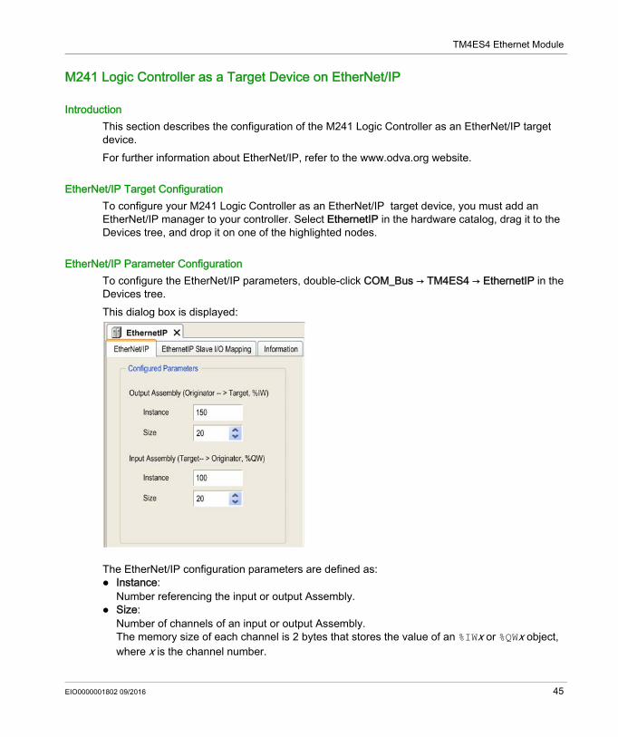
EtherNet/IP Parameter ConfigurationTo configure the EtherNet/IP parameters, double-click COM_Bus → TM4ES4 → EthernetIP in the Devices tree.This dialog box is displayed:
The EtherNet/IP configuration parameters are defined as: Instance:
Number referencing the input or output Assembly. Size:
Number of channels of an input or output Assembly.The memory size of each channel is 2 bytes that stores the value of an %IWx or %QWx object, where x is the channel number.
EIO0000001802 09/2016 45
TM4ES4 Ethernet Module
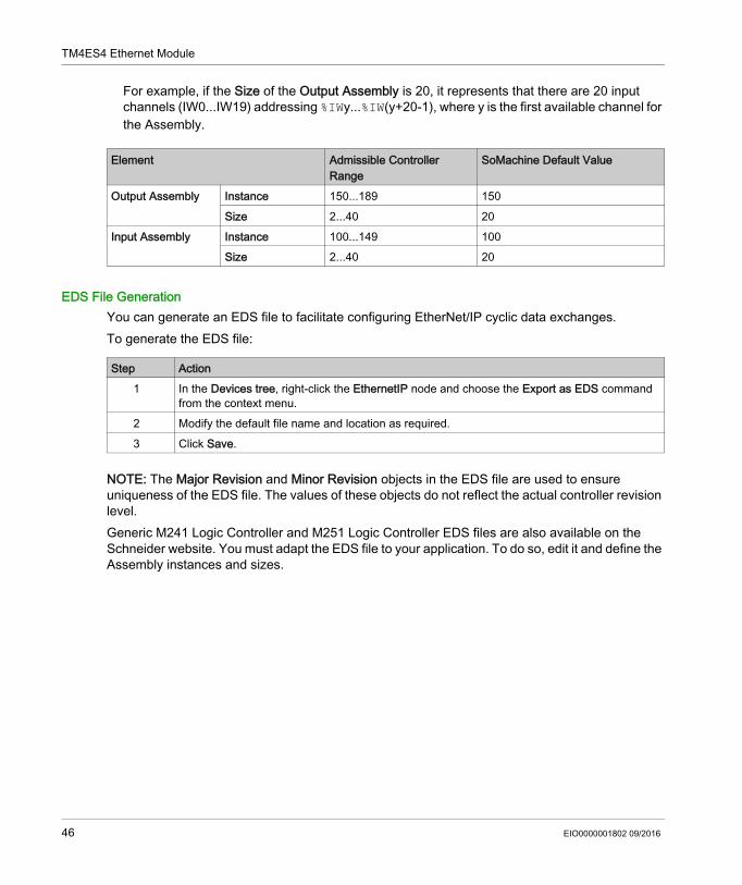
For example, if the Size of the Output Assembly is 20, it represents that there are 20 input channels (IW0...IW19) addressing %IWy...%IW(y+20-1), where y is the first available channel for the Assembly.
EDS File GenerationYou can generate an EDS file to facilitate configuring EtherNet/IP cyclic data exchanges.To generate the EDS file:
NOTE: The Major Revision and Minor Revision objects in the EDS file are used to ensure uniqueness of the EDS file. The values of these objects do not reflect the actual controller revision level.Generic M241 Logic Controller and M251 Logic Controller EDS files are also available on the Schneider website. You must adapt the EDS file to your application. To do so, edit it and define the Assembly instances and sizes.
Element Admissible Controller Range
SoMachine Default Value
Output Assembly Instance 150...189 150Size 2...40 20
Input Assembly Instance 100...149 100Size 2...40 20
Step Action1 In the Devices tree, right-click the EthernetIP node and choose the Export as EDS command
from the context menu. 2 Modify the default file name and location as required. 3 Click Save.
46 EIO0000001802 09/2016
TM4ES4 Ethernet Module
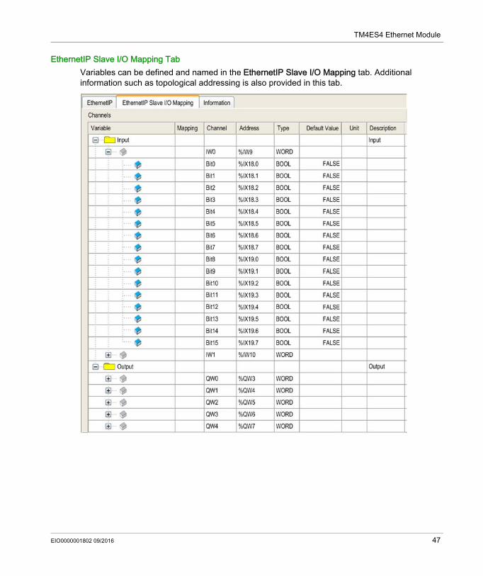
EthernetIP Slave I/O Mapping TabVariables can be defined and named in the EthernetIP Slave I/O Mapping tab. Additional information such as topological addressing is also provided in this tab.
EIO0000001802 09/2016 47
TM4ES4 Ethernet Module
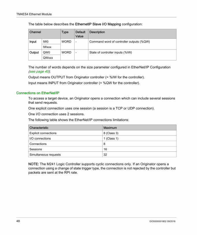
The table below describes the EthernetIP Slave I/O Mapping configuration:
The number of words depends on the size parameter configured in EtherNet/IP Configuration (see page 45).Output means OUTPUT from Originator controller (= %IW for the controller).Input means INPUT from Originator controller (= %QW for the controller).
Connections on EtherNet/IPTo access a target device, an Originator opens a connection which can include several sessions that send requests.One explicit connection uses one session (a session is a TCP or UDP connection). One I/O connection uses 2 sessions.The following table shows the EtherNet/IP connections limitations:
NOTE: The M241 Logic Controller supports cyclic connections only. If an Originator opens a connection using a change of state trigger type, the connection is not rejected by the controller but packets are sent at the RPI rate.
Channel Type Default Value
Description
Input IW0 WORD - Command word of controller outputs (%QW)IWxxx
Output QW0 WORD - State of controller inputs (%IW)QWxxx
Characteristic MaximumExplicit connections 8 (Class 3)I/O connections 1 (Class 1)Connections 8Sessions 16Simultaneous requests 32
48 EIO0000001802 09/2016
TM4ES4 Ethernet Module
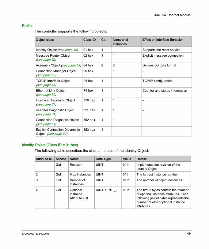
ProfileThe controller supports the following objects:
Identity Object (Class ID = 01 hex)The following table describes the class attributes of the Identity Object:
Object class Class ID Cat. Number of Instances
Effect on Interface Behavior
Identity Object (see page 49) 01 hex 1 1 Supports the reset serviceMessage Router Object (see page 52)
02 hex 1 1 Explicit message connection
Assembly Object (see page 54) 04 hex 2 2 Defines I/O data formatConnection Manager Object (see page 56)
06 hex 1 –
TCP/IP Interface Object (see page 58)
F5 hex 1 1 TCP/IP configuration
Ethernet Link Object (see page 60)
F6 hex 1 1 Counter and status information
Interface Diagnostic Object (see page 61)
350 hex 1 1 –
Scanner Diagnostic Object (see page 61)
351 hex 1 1 –
Connection Diagnostic Object (see page 61)
352 hex 1 1 –
Explicit Connection Diagnostic Object (see page 62)
353 hex 1 1 –
Attribute ID Access Name Data Type Value Details1 Get Revision UINT 01 h Implementation revision of the
Identity Object2 Get Max Instances UINT 01 h The largest instance number3 Get Number of
InstancesUINT 01 h The number of object instances
4 Get Optional Instance Attribute List
UINT, UINT [ ] 00 h The first 2 bytes contain the number of optional instance attributes. Each following pair of bytes represents the number of other optional instance attributes.
EIO0000001802 09/2016 49
TM4ES4 Ethernet Module
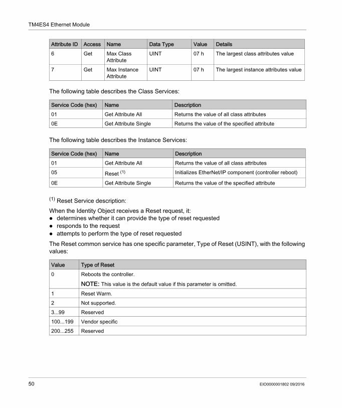
The following table describes the Class Services:
The following table describes the Instance Services:
(1) Reset Service description: When the Identity Object receives a Reset request, it: determines whether it can provide the type of reset requested responds to the request attempts to perform the type of reset requestedThe Reset common service has one specific parameter, Type of Reset (USINT), with the following values:
6 Get Max Class Attribute
UINT 07 h The largest class attributes value
7 Get Max Instance Attribute
UINT 07 h The largest instance attributes value
Service Code (hex) Name Description01 Get Attribute All Returns the value of all class attributes0E Get Attribute Single Returns the value of the specified attribute
Service Code (hex) Name Description01 Get Attribute All Returns the value of all class attributes05 Reset (1) Initializes EtherNet/IP component (controller reboot)
0E Get Attribute Single Returns the value of the specified attribute
Value Type of Reset0 Reboots the controller.
NOTE: This value is the default value if this parameter is omitted.
1 Reset Warm.2 Not supported.3...99 Reserved100...199 Vendor specific200...255 Reserved
Attribute ID Access Name Data Type Value Details
50 EIO0000001802 09/2016
TM4ES4 Ethernet Module
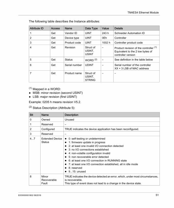
The following table describes the Instance attributes:
(1) Mapped in a WORD: MSB: minor revision (second USINT) LSB: major revision (first USINT)Example: 0205 h means revision V5.2.(2) Status Description (Attribute 5):
Attribute ID Access Name Data Type Value Details1 Get Vendor ID UINT 243 h Schneider Automation ID2 Get Device type UINT 0Eh Controller3 Get Product code UINT 1002 h Controller product code4 Get Revision Struct of
USINT, USINT
– Product revision of the controller (1)
Equivalent to the 2 low bytes of controller version
5 Get Status WORD (2) – See definition in the table below
6 Get Serial number UDINT – Serial number of the controllerXX + 3 LSB of MAC address
7 Get Product name Struct of USINT, STRING
– –
Bit Name Description0 Owned Unused1 Reserved –2 Configured TRUE indicates the device application has been reconfigured.3 Reserved –4...7 Extended Device
Status 0: self-testing or undetermined 1: firmware update in progress 2: at least one invalid I/O connection detected 3: no I/O connections established 4: non-volatile configuration invalid 5: non recoverable error detected 6: at least one I/O connection in RUNNING state 7: at least one I/O connection established, all in idle mode 8: reserved 9...15: unused
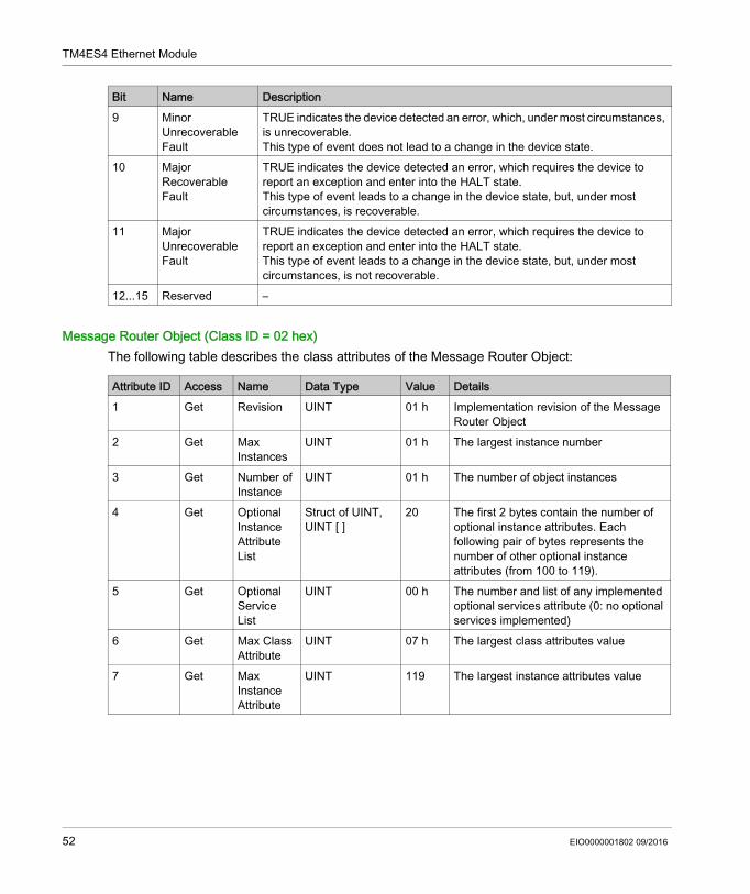
8 Minor Recoverable Fault
TRUE indicates the device detected an error, which, under most circumstances, is recoverable.This type of event does not lead to a change in the device state.
EIO0000001802 09/2016 51
TM4ES4 Ethernet Module
Message Router Object (Class ID = 02 hex)The following table describes the class attributes of the Message Router Object:
9 Minor Unrecoverable Fault
TRUE indicates the device detected an error, which, under most circumstances, is unrecoverable.This type of event does not lead to a change in the device state.
10 Major Recoverable Fault
TRUE indicates the device detected an error, which requires the device to report an exception and enter into the HALT state.This type of event leads to a change in the device state, but, under most circumstances, is recoverable.
11 Major Unrecoverable Fault
TRUE indicates the device detected an error, which requires the device to report an exception and enter into the HALT state.This type of event leads to a change in the device state, but, under most circumstances, is not recoverable.
12...15 Reserved –
Bit Name Description
Attribute ID Access Name Data Type Value Details1 Get Revision UINT 01 h Implementation revision of the Message
Router Object2 Get Max
InstancesUINT 01 h The largest instance number
3 Get Number of Instance
UINT 01 h The number of object instances
4 Get Optional Instance Attribute List
Struct of UINT, UINT [ ]
20 The first 2 bytes contain the number of optional instance attributes. Each following pair of bytes represents the number of other optional instance attributes (from 100 to 119).
5 Get Optional Service List
UINT 00 h The number and list of any implemented optional services attribute (0: no optional services implemented)
6 Get Max Class Attribute
UINT 07 h The largest class attributes value
7 Get Max Instance Attribute
UINT 119 The largest instance attributes value
52 EIO0000001802 09/2016
TM4ES4 Ethernet Module
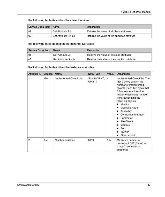
The following table describes the Class Services:
The following table describes the Instance Services:
The following table describes the Instance attributes:
Service Code (hex) Name Description01 Get Attribute All Returns the value of all class attributes0E Get Attribute Single Returns the value of the specified attribute
Service Code (hex) Name Description01 Get Attribute All Returns the value of all class attributes0E Get Attribute Single Returns the value of the specified attribute
Attribute ID Access Name Data Type Value Description1 Get Implemented Object List Struct of UINT,
UINT [ ]– Implemented Object list. The
first 2 bytes contain the number of implemented objects. Each two bytes that follow represent another implemented class number. This list contains the following objects: Identity Message Router Assembly Connection Manager Parameter File Object Modbus Port TCP/IP Ethernet Link
2 Get Number available UINT 512 Maximum number of concurrent CIP (Class1 or Class 3) connections supported
EIO0000001802 09/2016 53
TM4ES4 Ethernet Module
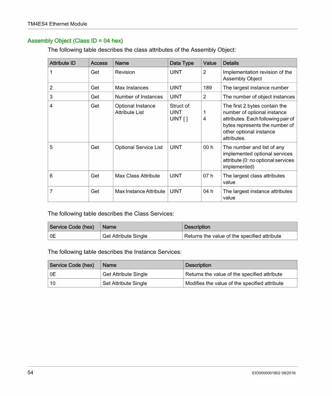
Assembly Object (Class ID = 04 hex)The following table describes the class attributes of the Assembly Object:
The following table describes the Class Services:
The following table describes the Instance Services:
Attribute ID Access Name Data Type Value Details1 Get Revision UINT 2 Implementation revision of the
Assembly Object2 Get Max Instances UINT 189 The largest instance number3 Get Number of Instances UINT 2 The number of object instances4 Get Optional Instance
Attribute ListStruct of:UINTUINT [ ]
14
The first 2 bytes contain the number of optional instance attributes. Each following pair of bytes represents the number of other optional instance attributes.
5 Get Optional Service List UINT 00 h The number and list of any implemented optional services attribute (0: no optional services implemented)
6 Get Max Class Attribute UINT 07 h The largest class attributes value
7 Get Max Instance Attribute UINT 04 h The largest instance attributes value
Service Code (hex) Name Description0E Get Attribute Single Returns the value of the specified attribute
Service Code (hex) Name Description0E Get Attribute Single Returns the value of the specified attribute10 Set Attribute Single Modifies the value of the specified attribute
54 EIO0000001802 09/2016
TM4ES4 Ethernet Module
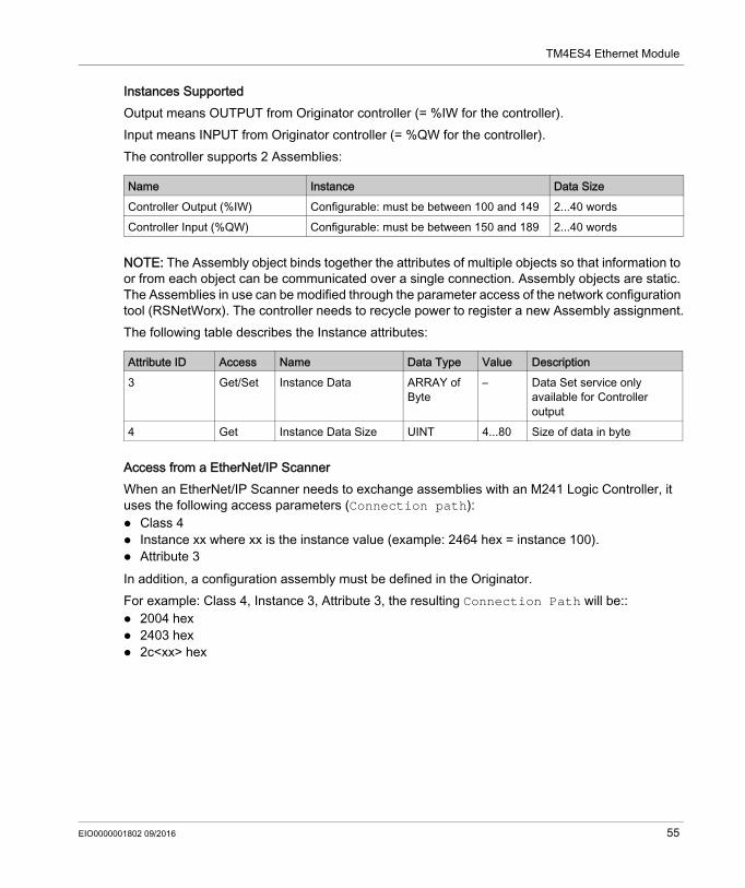
Instances SupportedOutput means OUTPUT from Originator controller (= %IW for the controller).Input means INPUT from Originator controller (= %QW for the controller).The controller supports 2 Assemblies:
NOTE: The Assembly object binds together the attributes of multiple objects so that information to or from each object can be communicated over a single connection. Assembly objects are static.The Assemblies in use can be modified through the parameter access of the network configuration tool (RSNetWorx). The controller needs to recycle power to register a new Assembly assignment.The following table describes the Instance attributes:
Access from a EtherNet/IP ScannerWhen an EtherNet/IP Scanner needs to exchange assemblies with an M241 Logic Controller, it uses the following access parameters (Connection path): Class 4 Instance xx where xx is the instance value (example: 2464 hex = instance 100). Attribute 3In addition, a configuration assembly must be defined in the Originator.For example: Class 4, Instance 3, Attribute 3, the resulting Connection Path will be:: 2004 hex 2403 hex 2c<xx> hex
Name Instance Data SizeController Output (%IW) Configurable: must be between 100 and 149 2...40 wordsController Input (%QW) Configurable: must be between 150 and 189 2...40 words
Attribute ID Access Name Data Type Value Description3 Get/Set Instance Data ARRAY of
Byte– Data Set service only
available for Controller output
4 Get Instance Data Size UINT 4...80 Size of data in byte
EIO0000001802 09/2016 55
TM4ES4 Ethernet Module
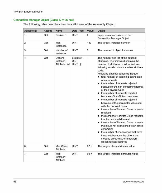
Connection Manager Object (Class ID = 06 hex)The following table describes the class attributes of the Assembly Object:
Attribute ID Access Name Data Type Value Details1 Get Revision UINT 2 Implementation revision of the
Connection Manager Object2 Get Max
InstancesUINT 189 The largest instance number
3 Get Number of Instances
UINT 2 The number of object instances
4 Get Optional Instance Attribute List
Struct of:UINTUINT [ ]
– The number and list of the optional attributes. The first word contains the number of attributes to follow and each following word contains another attribute code.Following optional attributes include: total number of incoming connection
open requests the number of requests rejected
because of the non-conforming format of the Forward Open
the number of requests rejected because of insufficient resources
the number of requests rejected because of the parameter value sent with the Forward Open
the number of Forward Close requests received
the number of Forward Close requests that had an invalid format
the number of Forward Close requests that could not be matched to an active connection
the number of connections that have timed out because the other side stopped producing, or a network disconnection occurred
6 Get Max Class Attribute
UINT 07 h The largest class attributes value
7 Get Max Instance Attribute
UINT 08 h The largest instance attributes value
56 EIO0000001802 09/2016
TM4ES4 Ethernet Module
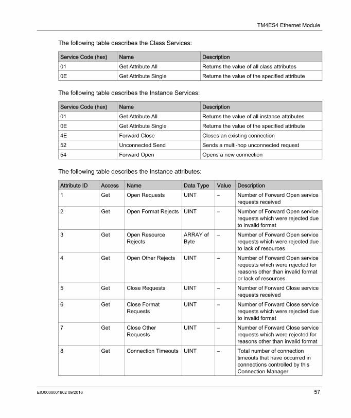
The following table describes the Class Services:
The following table describes the Instance Services:
The following table describes the Instance attributes:
Service Code (hex) Name Description01 Get Attribute All Returns the value of all class attributes0E Get Attribute Single Returns the value of the specified attribute
Service Code (hex) Name Description01 Get Attribute All Returns the value of all instance attributes0E Get Attribute Single Returns the value of the specified attribute4E Forward Close Closes an existing connection52 Unconnected Send Sends a multi-hop unconnected request54 Forward Open Opens a new connection
Attribute ID Access Name Data Type Value Description1 Get Open Requests UINT – Number of Forward Open service
requests received 2 Get Open Format Rejects UINT – Number of Forward Open service
requests which were rejected due to invalid format
3 Get Open Resource Rejects
ARRAY of Byte
– Number of Forward Open service requests which were rejected due to lack of resources
4 Get Open Other Rejects UINT – Number of Forward Open service requests which were rejected for reasons other than invalid format or lack of resources
5 Get Close Requests UINT – Number of Forward Close service requests received
6 Get Close Format Requests
UINT – Number of Forward Close service requests which were rejected due to invalid format
7 Get Close Other Requests
UINT – Number of Forward Close service requests which were rejected for reasons other than invalid format
8 Get Connection Timeouts UINT – Total number of connection timeouts that have occurred in connections controlled by this Connection Manager
EIO0000001802 09/2016 57
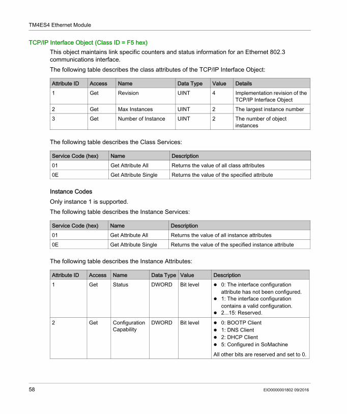
TM4ES4 Ethernet Module
TCP/IP Interface Object (Class ID = F5 hex)This object maintains link specific counters and status information for an Ethernet 802.3 communications interface.The following table describes the class attributes of the TCP/IP Interface Object:
The following table describes the Class Services:
Instance CodesOnly instance 1 is supported.The following table describes the Instance Services:
The following table describes the Instance Attributes:
Attribute ID Access Name Data Type Value Details1 Get Revision UINT 4 Implementation revision of the
TCP/IP Interface Object2 Get Max Instances UINT 2 The largest instance number3 Get Number of Instance UINT 2 The number of object
instances
Service Code (hex) Name Description01 Get Attribute All Returns the value of all class attributes0E Get Attribute Single Returns the value of the specified attribute
Service Code (hex) Name Description01 Get Attribute All Returns the value of all instance attributes0E Get Attribute Single Returns the value of the specified instance attribute
Attribute ID Access Name Data Type Value Description1 Get Status DWORD Bit level 0: The interface configuration
attribute has not been configured. 1: The interface configuration
contains a valid configuration. 2...15: Reserved.
2 Get Configuration Capability
DWORD Bit level 0: BOOTP Client 1: DNS Client 2: DHCP Client 5: Configured in SoMachine
All other bits are reserved and set to 0.
58 EIO0000001802 09/2016
TM4ES4 Ethernet Module
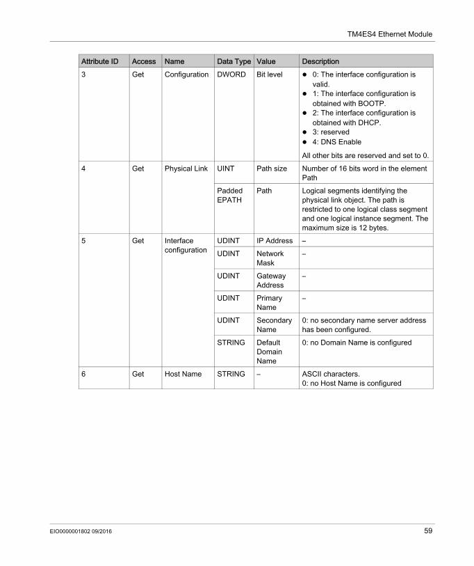
3 Get Configuration DWORD Bit level 0: The interface configuration is valid.
1: The interface configuration is obtained with BOOTP.
2: The interface configuration is obtained with DHCP.
3: reserved 4: DNS Enable
All other bits are reserved and set to 0.4 Get Physical Link UINT Path size Number of 16 bits word in the element
PathPadded EPATH
Path Logical segments identifying the physical link object. The path is restricted to one logical class segment and one logical instance segment. The maximum size is 12 bytes.
5 Get Interface configuration
UDINT IP Address –UDINT Network
Mask–
UDINT Gateway Address
–
UDINT Primary Name
–
UDINT Secondary Name
0: no secondary name server address has been configured.
STRING Default Domain Name
0: no Domain Name is configured
6 Get Host Name STRING – ASCII characters.0: no Host Name is configured
Attribute ID Access Name Data Type Value Description
EIO0000001802 09/2016 59
TM4ES4 Ethernet Module
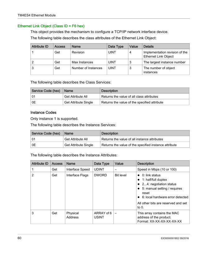
Ethernet Link Object (Class ID = F6 hex)This object provides the mechanism to configure a TCP/IP network interface device.The following table describes the class attributes of the Ethernet Link Object:
The following table describes the Class Services:
Instance CodesOnly instance 1 is supported.The following table describes the Instance Services:
The following table describes the Instance Attributes:
Attribute ID Access Name Data Type Value Details1 Get Revision UINT 4 Implementation revision of the
Ethernet Link Object2 Get Max Instances UINT 3 The largest instance number3 Get Number of Instances UINT 3 The number of object
instances
Service Code (hex) Name Description01 Get Attribute All Returns the value of all class attributes0E Get Attribute Single Returns the value of the specified attribute
Service Code (hex) Name Description01 Get Attribute All Returns the value of all instance attributes0E Get Attribute Single Returns the value of the specified instance attribute
Attribute ID Access Name Data Type Value Description1 Get Interface Speed UDINT – Speed in Mbps (10 or 100)2 Get Interface Flags DWORD Bit level 0: link status
1: half/full duplex 2...4: negotiation status 5: manual setting / requires
reset 6: local hardware error detected
All other bits are reserved and set to 0.
3 Get Physical Address
ARRAY of 6 USINT
– This array contains the MAC address of the product.Format: XX-XX-XX-XX-XX-XX
60 EIO0000001802 09/2016
TM4ES4 Ethernet Module
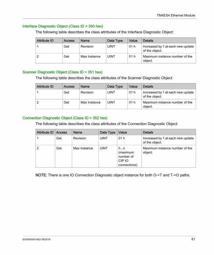
Interface Diagnostic Object (Class ID = 350 hex)The following table describes the class attributes of the Interface Diagnostic Object:
Scanner Diagnostic Object (Class ID = 351 hex)The following table describes the class attributes of the Scanner Diagnostic Object:
Connection Diagnostic Object (Class ID = 352 hex)The following table describes the class attributes of the Connection Diagnostic Object:
NOTE: There is one IO Connection Diagnostic object instance for both O->T and T->O paths.
Attribute ID Access Name Data Type Value Details1 Get Revision UINT 01 h Increased by 1 at each new update
of the object.2 Get Max Instance UINT 01 h Maximum instance number of the
object.
Attribute ID Access Name Data Type Value Details1 Get Revision UINT 01 h Increased by 1 at each new update
of the object.2 Get Max Instance UINT 01 h Maximum instance number of the
object.
Attribute ID Access Name Data Type Value Details1 Get Revision UINT 01 h Increased by 1 at each new update
of the object.2 Get Max Instance UINT 0...n
(maximum number of CIP IO connections)
Maximum instance number of the object.
EIO0000001802 09/2016 61
TM4ES4 Ethernet Module
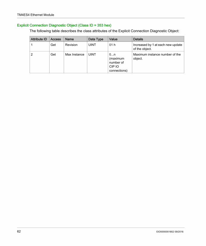
Explicit Connection Diagnostic Object (Class ID = 353 hex)The following table describes the class attributes of the Explicit Connection Diagnostic Object:
Attribute ID Access Name Data Type Value Details1 Get Revision UINT 01 h Increased by 1 at each new update
of the object.2 Get Max Instance UINT 0...n
(maximum number of CIP IO connections)
Maximum instance number of the object.
62 EIO0000001802 09/2016
TM4ES4 Ethernet Module
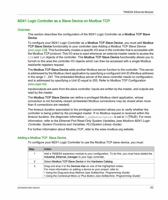
M241 Logic Controller as a Slave Device on Modbus TCP
OverviewThis section describes the configuration of the M241 Logic Controller as a Modbus TCP Slave Device.To configure your M241 Logic Controller as a Modbus TCP Slave Device, you must add Modbus TCP Slave Device functionality to your controller (see Adding a Modbus TCP Slave Device (see page 63)). This functionality creates a specific I/O area in the controller that is accessible with the Modbus TCP protocol. This I/O area is used whenever an external master needs to access the %IW and %QW objects of the controller. This Modbus TCP Slave Device functionality allows you to furnish to this area the controller I/O objects which can then be accessed with a single Modbus read/write registers request.The Modbus TCP Slave Device adds another Modbus server function to the controller. This server is addressed by the Modbus client application by specifying a configured Unit ID (Modbus address) in the range 1...247. The embedded Modbus server of the slave controller needs no configuration, and is addressed by specifying a Unit ID equal to 255. Refer to Modbus TCP Configuration (see page 64).Inputs/outputs are seen from the slave controller: inputs are written by the master, and outputs are read by the master.The Modbus TCP Slave Device can define a privileged Modbus client application, whose connection is not forcefully closed (embedded Modbus connections may be closed when more than 8 connections are needed).The timeout duration associated to the privileged connection allows you to verify whether the controller is being polled by the privileged master. If no Modbus request is received within the timeout duration, the diagnostic information i_byMasterIpLost is set to 1 (TRUE). For more information, refer to the Ethernet Port Read-Only System Variables (see Modicon M241 Logic Controller, System Functions and Variables, PLCSystem Library Guide).For further information about Modbus TCP, refer to the www.modbus.org website.
Adding a Modbus TCP Slave DeviceTo configure your M241 Logic Controller to use the Modbus TCP slave device, you must:
Step Action1 Add a TM4ES4 expansion module to your configuration. To do this, you must have added the
Industrial_Ethernet_manager to your logic controller.2 Select Modbus TCP Slave Device in the Hardware Catalog.3 Drag and drop it to the Devices tree on one of the highlighted nodes.
For more information on adding a device to your project, refer to:• Using the Drag-and-drop Method (see SoMachine, Programming Guide)• Using the Contextual Menu or Plus Button (see SoMachine, Programming Guide)
EIO0000001802 09/2016 63
TM4ES4 Ethernet Module
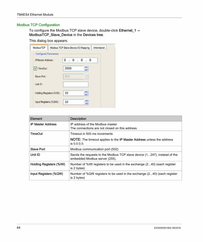
Modbus TCP ConfigurationTo configure the Modbus TCP slave device, double-click Ethernet_1 → ModbusTCP_Slave_Device in the Devices tree.This dialog box appears:
Element DescriptionIP Master Address IP address of the Modbus master
The connections are not closed on this address.TimeOut Timeout in 500 ms increments
NOTE: The timeout applies to the IP Master Address unless the address is 0.0.0.0.
Slave Port Modbus communication port (502)Unit ID Sends the requests to the Modbus TCP slave device (1...247), instead of the
embedded Modbus server (255).Holding Registers (%IW) Number of %IW registers to be used in the exchange (2...40) (each register
is 2 bytes)Input Registers (%QW) Number of %QW registers to be used in the exchange (2...40) (each register
is 2 bytes)
64 EIO0000001802 09/2016
TM4ES4 Ethernet Module
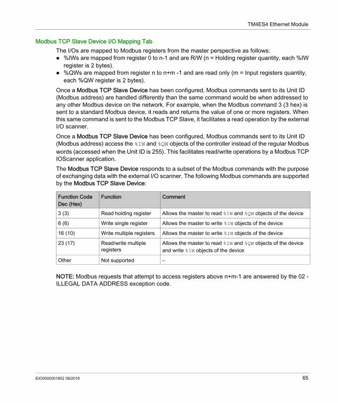
Modbus TCP Slave Device I/O Mapping TabThe I/Os are mapped to Modbus registers from the master perspective as follows: %IWs are mapped from register 0 to n-1 and are R/W (n = Holding register quantity, each %IW
register is 2 bytes). %QWs are mapped from register n to n+m -1 and are read only (m = Input registers quantity,
each %QW register is 2 bytes).Once a Modbus TCP Slave Device has been configured, Modbus commands sent to its Unit ID (Modbus address) are handled differently than the same command would be when addressed to any other Modbus device on the network. For example, when the Modbus command 3 (3 hex) is sent to a standard Modbus device, it reads and returns the value of one or more registers. When this same command is sent to the Modbus TCP Slave, it facilitates a read operation by the external I/O scanner.Once a Modbus TCP Slave Device has been configured, Modbus commands sent to its Unit ID (Modbus address) access the %IW and %QW objects of the controller instead of the regular Modbus words (accessed when the Unit ID is 255). This facilitates read/write operations by a Modbus TCP IOScanner application.The Modbus TCP Slave Device responds to a subset of the Modbus commands with the purpose of exchanging data with the external I/O scanner. The following Modbus commands are supported by the Modbus TCP Slave Device:
NOTE: Modbus requests that attempt to access registers above n+m-1 are answered by the 02 - ILLEGAL DATA ADDRESS exception code.
Function Code Dec (Hex)
Function Comment
3 (3) Read holding register Allows the master to read %IW and %QW objects of the device
6 (6) Write single register Allows the master to write %IW objects of the device
16 (10) Write multiple registers Allows the master to write %IW objects of the device
23 (17) Read/write multiple registers
Allows the master to read %IW and %QW objects of the device and write %IW objects of the device
Other Not supported –
EIO0000001802 09/2016 65
TM4ES4 Ethernet Module
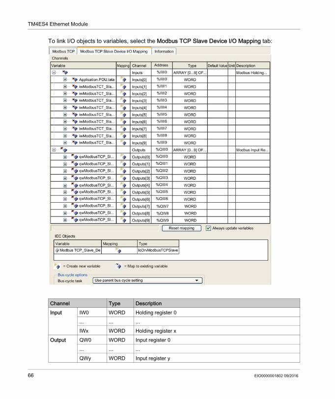
To link I/O objects to variables, select the Modbus TCP Slave Device I/O Mapping tab:
Channel Type DescriptionInput IW0 WORD Holding register 0
... ... ...IWx WORD Holding register x
Output QW0 WORD Input register 0... ... ...QWy WORD Input register y
66 EIO0000001802 09/2016

TM4ES4 Ethernet Module
The number of words depends on the Holding Registers (%IW) and Input Registers (%QW) parameters of the Modbus TCP tab.NOTE: Output means OUTPUT from Originator controller (%IW for the controller). Input means INPUT from Originator controller (%QW for the controller).NOTE: The Modbus TCP slave device refreshes the %IW and %QW registers as a single time-consistent unit, synchronized with the IEC tasks (MAST task by default). By contrast, the embedded Modbus TCP server only ensures time-consistency for one word (2 bytes). If your application requires time-consistency for more than one word (2 bytes), use the Modbus TCP Slave Device.
Bus Cycle OptionsSelect the Bus cycle task to use: Use parent bus cycle setting (the default), MAST An existing task of the projectThere is a corresponding Bus cycle task parameter in the I/O mapping editor of the device that contains the Modbus TCP slave device. This parameter defines the task responsible for refreshing the %IW and %QW registers.
EIO0000001802 09/2016 67
TM4ES4 Ethernet Module
Firewall Configuration
Section 2.2Firewall Configuration
IntroductionThis section describes how to configure the firewall of the Modicon M241 Logic Controller.
What Is in This Section?This section contains the following topics:
Topic PageIntroduction 69Dynamic Changes Procedure 71Firewall Behavior 72Script File Syntax 74
68 EIO0000001802 09/2016
TM4ES4 Ethernet Module
Introduction
Firewall PresentationIn general, firewalls help protect network security zone perimeters by blocking unauthorized access and permitting authorized access. A firewall is a device or set of devices configured to permit, deny, encrypt, decrypt, or proxy traffic between different security zones based upon a set of rules and other criteria.Process control devices and high-speed manufacturing machines require fast data throughput and often cannot tolerate the latency introduced by an aggressive security strategy inside the control network. Firewalls, therefore, play a significant role in a security strategy by providing levels of protection at the perimeters of the network. Firewalls are important part of an overall, system level strategy.NOTE: Schneider Electric adheres to industry best practices in the development and implemen-tation of control systems. This includes a "Defense-in-Depth" approach to secure an Industrial Control System. This approach places the controllers behind one or more firewalls to restrict access to authorized personnel and protocols only.
Firewall ConfigurationThere are 3 ways to manage the controller firewall configuration: Static configuration, Dynamic changes, Application settings.Script files are used in the static configuration and for dynamic changes.
WARNINGUNAUTHENTICATED ACCESS AND SUBSEQUENT UNAUTHORIZED MACHINE OPERATION Evaluate whether your environment or your machines are connected to your critical
infrastructure and, if so, take appropriate steps in terms of prevention, based on Defense-in-Depth, before connecting the automation system to any network.
Limit the number of devices connected to a network to the minimum necessary. Isolate your industrial network from other networks inside your company. Protect any network against unintended access by using firewalls, VPN, or other, proven
security measures. Monitor activities within your systems. Prevent subject devices from direct access or direct link by unauthorized parties or unauthen-
ticated actions. Prepare a recovery plan including backup of your system and process information.Failure to follow these instructions can result in death, serious injury, or equipment damage.
EIO0000001802 09/2016 69
TM4ES4 Ethernet Module
Static ConfigurationThe static configuration is loaded at the controller boot.The controller firewall can be statically configured by managing a default script file located in the controller. The path to this file is /Usr/Cfg/FirewallDefault.cmd.
Dynamic ChangesAfter the controller boot, the controller firewall configuration can be changed by the use of script files.There are 2 ways to load these dynamic changes: Using a physical SD card (see page 71), Using a function block (see page 71) in the application.
Application SettingsRefer to Ethernet Configuration (see Modicon M241 Logic Controller, Programming Guide).
70 EIO0000001802 09/2016
TM4ES4 Ethernet Module
Dynamic Changes Procedure
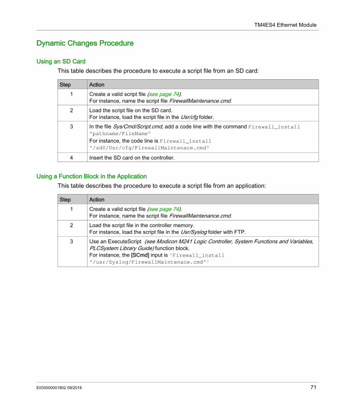
Using an SD CardThis table describes the procedure to execute a script file from an SD card:
Using a Function Block in the ApplicationThis table describes the procedure to execute a script file from an application:
Step Action1 Create a valid script file (see page 74).
For instance, name the script file FirewallMaintenance.cmd.2 Load the script file on the SD card.
For instance, load the script file in the Usr/cfg folder.3 In the file Sys/Cmd/Script.cmd, add a code line with the command Firewall_install
"pathname/FileName"For instance, the code line is Firewall_install "/sd0/Usr/cfg/FirewallMaintenace.cmd"
4 Insert the SD card on the controller.
Step Action1 Create a valid script file (see page 74).
For instance, name the script file FirewallMaintenance.cmd.2 Load the script file in the controller memory.
For instance, load the script file in the Usr/Syslog folder with FTP.3 Use an ExecuteScript (see Modicon M241 Logic Controller, System Functions and Variables,
PLCSystem Library Guide) function block.For instance, the [SCmd] input is 'Firewall_install "/usr/Syslog/FirewallMaintenace.cmd"'
EIO0000001802 09/2016 71
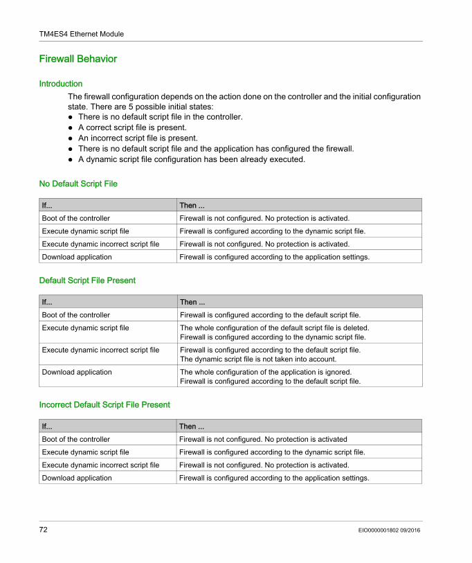
TM4ES4 Ethernet Module
Firewall Behavior
IntroductionThe firewall configuration depends on the action done on the controller and the initial configuration state. There are 5 possible initial states: There is no default script file in the controller. A correct script file is present. An incorrect script file is present. There is no default script file and the application has configured the firewall. A dynamic script file configuration has been already executed.
No Default Script File
Default Script File Present
Incorrect Default Script File Present
If... Then ...Boot of the controller Firewall is not configured. No protection is activated.Execute dynamic script file Firewall is configured according to the dynamic script file.Execute dynamic incorrect script file Firewall is not configured. No protection is activated.Download application Firewall is configured according to the application settings.
If... Then ...Boot of the controller Firewall is configured according to the default script file.Execute dynamic script file The whole configuration of the default script file is deleted.
Firewall is configured according to the dynamic script file.Execute dynamic incorrect script file Firewall is configured according to the default script file.
The dynamic script file is not taken into account.Download application The whole configuration of the application is ignored.
Firewall is configured according to the default script file.
If... Then ...Boot of the controller Firewall is not configured. No protection is activatedExecute dynamic script file Firewall is configured according to the dynamic script file.Execute dynamic incorrect script file Firewall is not configured. No protection is activated.Download application Firewall is configured according to the application settings.
72 EIO0000001802 09/2016
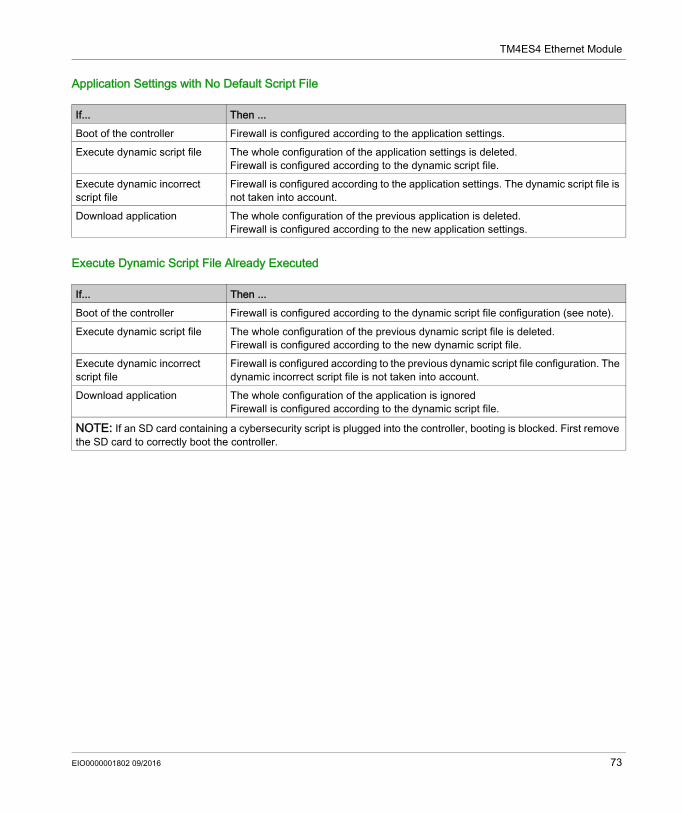
TM4ES4 Ethernet Module
Application Settings with No Default Script File
Execute Dynamic Script File Already Executed
If... Then ...Boot of the controller Firewall is configured according to the application settings.Execute dynamic script file The whole configuration of the application settings is deleted.
Firewall is configured according to the dynamic script file.Execute dynamic incorrect script file
Firewall is configured according to the application settings. The dynamic script file is not taken into account.
Download application The whole configuration of the previous application is deleted.Firewall is configured according to the new application settings.
If... Then ...Boot of the controller Firewall is configured according to the dynamic script file configuration (see note).Execute dynamic script file The whole configuration of the previous dynamic script file is deleted.
Firewall is configured according to the new dynamic script file.Execute dynamic incorrect script file
Firewall is configured according to the previous dynamic script file configuration. The dynamic incorrect script file is not taken into account.
Download application The whole configuration of the application is ignoredFirewall is configured according to the dynamic script file.
NOTE: If an SD card containing a cybersecurity script is plugged into the controller, booting is blocked. First remove the SD card to correctly boot the controller.
EIO0000001802 09/2016 73
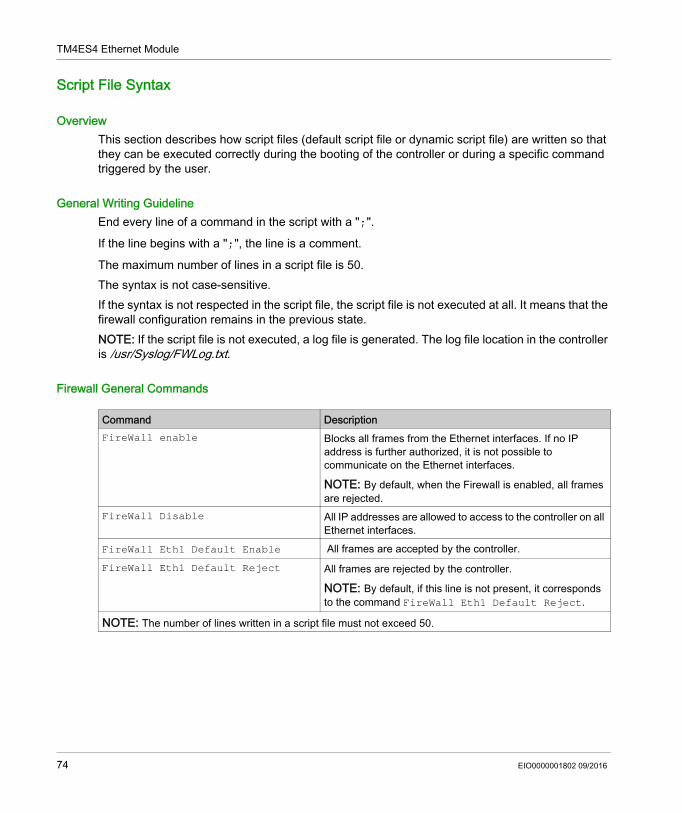
TM4ES4 Ethernet Module
Script File Syntax
OverviewThis section describes how script files (default script file or dynamic script file) are written so that they can be executed correctly during the booting of the controller or during a specific command triggered by the user.
General Writing GuidelineEnd every line of a command in the script with a ";".
If the line begins with a ";", the line is a comment.
The maximum number of lines in a script file is 50.The syntax is not case-sensitive.If the syntax is not respected in the script file, the script file is not executed at all. It means that the firewall configuration remains in the previous state.NOTE: If the script file is not executed, a log file is generated. The log file location in the controller is /usr/Syslog/FWLog.txt.
Firewall General Commands
Command DescriptionFireWall enable Blocks all frames from the Ethernet interfaces. If no IP
address is further authorized, it is not possible to communicate on the Ethernet interfaces.
NOTE: By default, when the Firewall is enabled, all frames are rejected.
FireWall Disable All IP addresses are allowed to access to the controller on all Ethernet interfaces.
FireWall Eth1 Default Enable All frames are accepted by the controller.FireWall Eth1 Default Reject All frames are rejected by the controller.
NOTE: By default, if this line is not present, it corresponds to the command FireWall Eth1 Default Reject.
NOTE: The number of lines written in a script file must not exceed 50.
74 EIO0000001802 09/2016
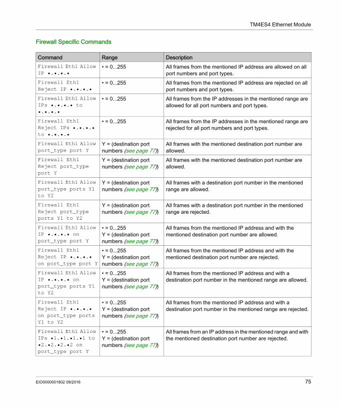
TM4ES4 Ethernet Module
Firewall Specific Commands
Command Range DescriptionFirewall Eth1 Allow IP •.•.•.•
• = 0...255 All frames from the mentioned IP address are allowed on all port numbers and port types.
Firewall Eth1 Reject IP •.•.•.•
• = 0...255 All frames from the mentioned IP address are rejected on all port numbers and port types.
Firewall Eth1 Allow IPs •.•.•.• to •.•.•.•
• = 0...255 All frames from the IP addresses in the mentioned range are allowed for all port numbers and port types.
Firewall Eth1 Reject IPs •.•.•.• to •.•.•.•
• = 0...255 All frames from the IP addresses in the mentioned range are rejected for all port numbers and port types.
Firewall Eth1 Allow port_type port Y
Y = (destination port numbers (see page 77))
All frames with the mentioned destination port number are allowed.
Firewall Eth1 Reject port_type port Y
Y = (destination port numbers (see page 77))
All frames with the mentioned destination port number are allowed.
Firewall Eth1 Allow port_type ports Y1 to Y2
Y = (destination port numbers (see page 77))
All frames with a destination port number in the mentioned range are allowed.
Firewall Eth1 Reject port_type ports Y1 to Y2
Y = (destination port numbers (see page 77))
All frames with a destination port number in the mentioned range are rejected.
Firewall Eth1 Allow IP •.•.•.• on port_type port Y
• = 0...255Y = (destination port numbers (see page 77))
All frames from the mentioned IP address and with the mentioned destination port number are allowed.
Firewall Eth1 Reject IP •.•.•.• on port_type port Y
• = 0...255Y = (destination port numbers (see page 77))
All frames from the mentioned IP address and with the mentioned destination port number are rejected.
Firewall Eth1 Allow IP •.•.•.• on port_type ports Y1 to Y2
• = 0...255Y = (destination port numbers (see page 77))
All frames from the mentioned IP address and with a destination port number in the mentioned range are allowed.
Firewall Eth1 Reject IP •.•.•.• on port_type ports Y1 to Y2
• = 0...255Y = (destination port numbers (see page 77))
All frames from the mentioned IP address and with a destination port number in the mentioned range are rejected.
Firewall Eth1 Allow IPs •1.•1.•1.•1 to •2.•2.•2.•2 on port_type port Y
• = 0...255Y = (destination port numbers (see page 77))
All frames from an IP address in the mentioned range and with the mentioned destination port number are rejected.
EIO0000001802 09/2016 75
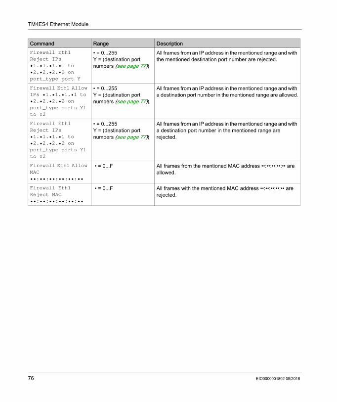
TM4ES4 Ethernet Module
Firewall Eth1 Reject IPs •1.•1.•1.•1 to •2.•2.•2.•2 on port_type port Y
• = 0...255Y = (destination port numbers (see page 77))
All frames from an IP address in the mentioned range and with the mentioned destination port number are rejected.
Firewall Eth1 Allow IPs •1.•1.•1.•1 to •2.•2.•2.•2 on port_type ports Y1 to Y2
• = 0...255Y = (destination port numbers (see page 77))
All frames from an IP address in the mentioned range and with a destination port number in the mentioned range are allowed.
Firewall Eth1 Reject IPs •1.•1.•1.•1 to •2.•2.•2.•2 on port_type ports Y1 to Y2
• = 0...255Y = (destination port numbers (see page 77))
All frames from an IP address in the mentioned range and with a destination port number in the mentioned range are rejected.
Firewall Eth1 Allow MAC ••:••:••:••:••:••
• = 0...F All frames from the mentioned MAC address ••:••:••:••:•• are allowed.
Firewall Eth1 Reject MAC ••:••:••:••:••:••
• = 0...F All frames with the mentioned MAC address ••:••:••:••:•• are rejected.
Command Range Description
76 EIO0000001802 09/2016
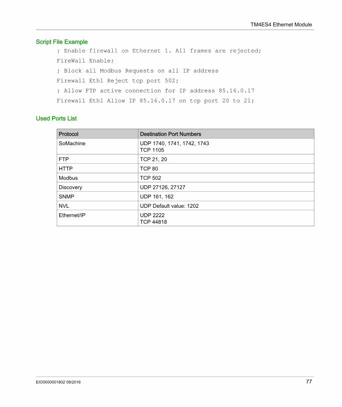
TM4ES4 Ethernet Module
Script File Example; Enable firewall on Ethernet 1. All frames are rejected;
FireWall Enable;
; Block all Modbus Requests on all IP address
Firewall Eth1 Reject tcp port 502;
; Allow FTP active connection for IP address 85.16.0.17
Firewall Eth1 Allow IP 85.16.0.17 on tcp port 20 to 21;
Used Ports List
Protocol Destination Port NumbersSoMachine UDP 1740, 1741, 1742, 1743
TCP 1105FTP TCP 21, 20HTTP TCP 80Modbus TCP 502Discovery UDP 27126, 27127SNMP UDP 161, 162NVL UDP Default value: 1202Ethernet/IP UDP 2222
TCP 44818
EIO0000001802 09/2016 77

TM4ES4 Ethernet Module
78 EIO0000001802 09/2016
Modicon TM4TM4PDPS1 PROFIBUS DP Slave ModuleEIO0000001802 09/2016
TM4PDPS1 PROFIBUS DP Slave Module
Chapter 3TM4PDPS1 PROFIBUS DP Slave Module
IntroductionThis chapter describes the configuration of the TM4PDPS1 PROFIBUS DP slave module.
What Is in This Chapter?This chapter contains the following sections:
Section Topic Page3.1 PROFIBUS DP Slave Module Configuration 803.2 Data Exchange 853.3 Diagnostic 91
EIO0000001802 09/2016 79
TM4PDPS1 PROFIBUS DP Slave Module
PROFIBUS DP Slave Module Configuration
Section 3.1PROFIBUS DP Slave Module Configuration
IntroductionThis section describes the configuration of the TM4PDPS1 PROFIBUS DP module.
What Is in This Section?This section contains the following topics:
Topic PageAdd a PROFIBUS DP Slave Module 81Configure the PROFIBUS DP Slave Module 82Input / Output Devices Objects 83
80 EIO0000001802 09/2016
TM4PDPS1 PROFIBUS DP Slave Module
Add a PROFIBUS DP Slave Module
OverviewWith the PROFIBUS protocol the data is exchanged according to the master-slave principle. Only the master can initialize communication. The slaves respond to requests from masters. Several masters can coexist on the same bus. In this case, the slave I/O can be read by all the masters. However, a single master has write access to the outputs. The number of data items exchanged is defined during the configuration.For the PROFIBUS master, the GSD file of the TM4PDPS1 module is located on Drive:\Program Files\Schneider Electric\SoMachine Software\V4.1\LogicBuilder\GSD\SE100E83.GSD.The GSD file is also available on www.schneider-electric.com.There are 2 types of exchange services supported by this module: I/O cyclic frames exchanges (see page 86) acyclic data exchanges with Profibus DPV1 function (see page 89)
Add a PROFIBUS DP Slave ModuleSelect the TM4PDPS1 module in the Hardware Catalog, drag it to the Devices tree, and drop it on the COM_Bus node.For more information on adding a device to your project, refer to:• Using the Drag-and-drop Method (see SoMachine, Programming Guide)• Using the Contextual Menu or Plus Button (see SoMachine, Programming Guide) NOTE: Adding PROFIBUS increases the associated task cycle time by several milliseconds and the starting time by several seconds.
EIO0000001802 09/2016 81
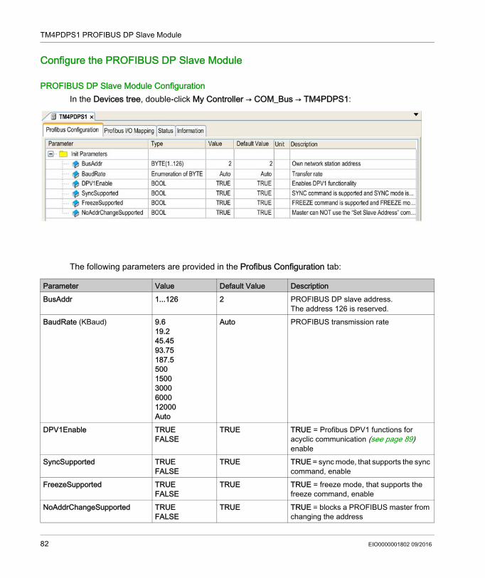
TM4PDPS1 PROFIBUS DP Slave Module
Configure the PROFIBUS DP Slave Module
PROFIBUS DP Slave Module ConfigurationIn the Devices tree, double-click My Controller → COM_Bus → TM4PDPS1:
The following parameters are provided in the Profibus Configuration tab:
Parameter Value Default Value DescriptionBusAddr 1...126 2 PROFIBUS DP slave address.
The address 126 is reserved.BaudRate (KBaud) 9.6
19.245.4593.75187.550015003000600012000Auto
Auto PROFIBUS transmission rate
DPV1Enable TRUEFALSE
TRUE TRUE = Profibus DPV1 functions for acyclic communication (see page 89) enable
SyncSupported TRUEFALSE
TRUE TRUE = sync mode, that supports the sync command, enable
FreezeSupported TRUEFALSE
TRUE TRUE = freeze mode, that supports the freeze command, enable
NoAddrChangeSupported TRUEFALSE
TRUE TRUE = blocks a PROFIBUS master from changing the address
82 EIO0000001802 09/2016
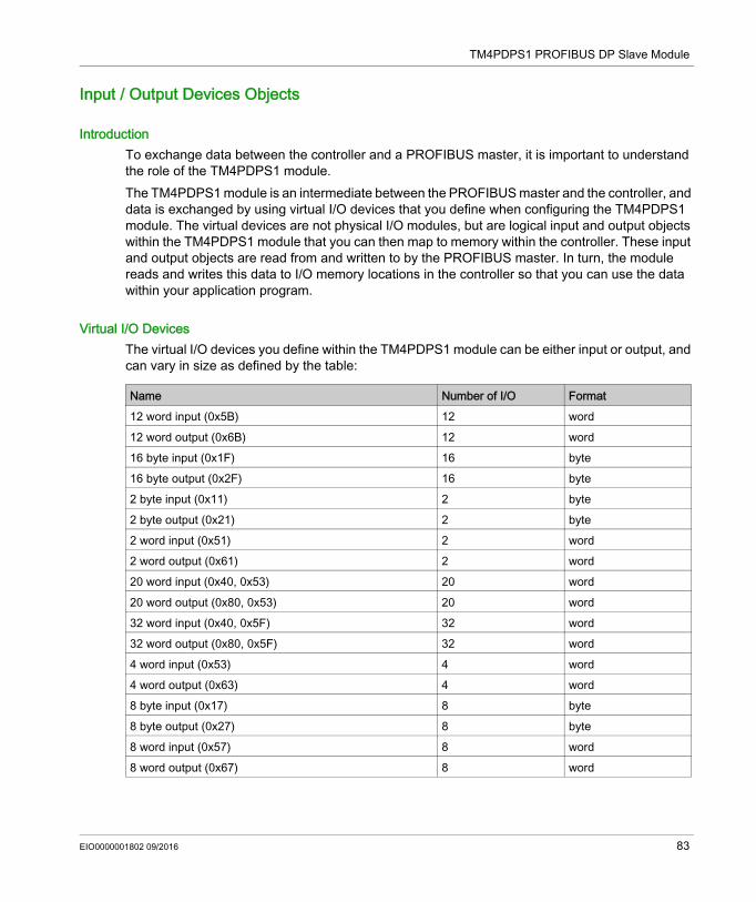
TM4PDPS1 PROFIBUS DP Slave Module
Input / Output Devices Objects
IntroductionTo exchange data between the controller and a PROFIBUS master, it is important to understand the role of the TM4PDPS1 module.The TM4PDPS1 module is an intermediate between the PROFIBUS master and the controller, and data is exchanged by using virtual I/O devices that you define when configuring the TM4PDPS1 module. The virtual devices are not physical I/O modules, but are logical input and output objects within the TM4PDPS1 module that you can then map to memory within the controller. These input and output objects are read from and written to by the PROFIBUS master. In turn, the module reads and writes this data to I/O memory locations in the controller so that you can use the data within your application program.
Virtual I/O DevicesThe virtual I/O devices you define within the TM4PDPS1 module can be either input or output, and can vary in size as defined by the table:
Name Number of I/O Format12 word input (0x5B) 12 word12 word output (0x6B) 12 word16 byte input (0x1F) 16 byte16 byte output (0x2F) 16 byte2 byte input (0x11) 2 byte2 byte output (0x21) 2 byte2 word input (0x51) 2 word2 word output (0x61) 2 word20 word input (0x40, 0x53) 20 word20 word output (0x80, 0x53) 20 word32 word input (0x40, 0x5F) 32 word32 word output (0x80, 0x5F) 32 word4 word input (0x53) 4 word4 word output (0x63) 4 word8 byte input (0x17) 8 byte8 byte output (0x27) 8 byte8 word input (0x57) 8 word8 word output (0x67) 8 word
EIO0000001802 09/2016 83

TM4PDPS1 PROFIBUS DP Slave Module
Once you have defined these virtual input and/or output devices within the TM4PDPS1 expansion module, you can then map these devices to memory locations within the controller. The type of memory objects you map these virtual I/O devices to depends on the type of exchange you define between the master and the slave.
84 EIO0000001802 09/2016
TM4PDPS1 PROFIBUS DP Slave Module
Data Exchange
Section 3.2Data Exchange
IntroductionThis section provides further information on the exchange of data between the TM4PDPS1 module and the PROFIBUS master.
What Is in This Section?This section contains the following topics:
Topic PageI/O Cyclic Exchange 86Acyclic Exchange with PROFIBUS DPV1 Functions 89
EIO0000001802 09/2016 85
TM4PDPS1 PROFIBUS DP Slave Module
I/O Cyclic Exchange
IntroductionIn order to exchange input / output data between the PROFIBUS DP slave module and the PROFIBUS master in a cyclic way, define the variables in the Profibus-Modules I/O Mapping tab.The %IW addresses of the controller are the output values supplied by the PROFIBUS DP master.
The %QW addresses of the controller are applied to the input of the PROFIBUS DP master.
NOTE: When you use the PROFIBUS module TM4PDPS1, it is mandatory to: configure a dedicated PROFIBUS task without watchdog (do not use the MAST task) assign the dedicated PROFIBUS task a lower priority than the MAST task (for example, if the
MAST task has a priority value 1, the TaskProfibus must have a priority value 10.) not set the PROFIBUS task cycle time faster than 10 ms. The typical cycle time of the bus cycle
task is 10 ms.For more information about PROFIBUS task configuration, refer to the SoMachine online help, chapter Programming with SoMachine / Device Editors / ProfibusDP Configuration Editor / ProfibusDP bus cycle task.
Create Your I/O Mapping Table for the TM4PDPS1 PROFIBUS DP Slave ModuleTo create your I/O mapping table for the TM4PDPS1, proceed as follows:
Step Action1 Select the Field Devices tab in the Hardware Catalog and click Connectivity.2 Select Profibus → Profibus I/O, choose the I/O device to add and drag-and-drop it onto
TM4PDPS1.Result: The module is added to My Controller → COM_Bus → TM4PDPS1 area of the Devices tree.
86 EIO0000001802 09/2016
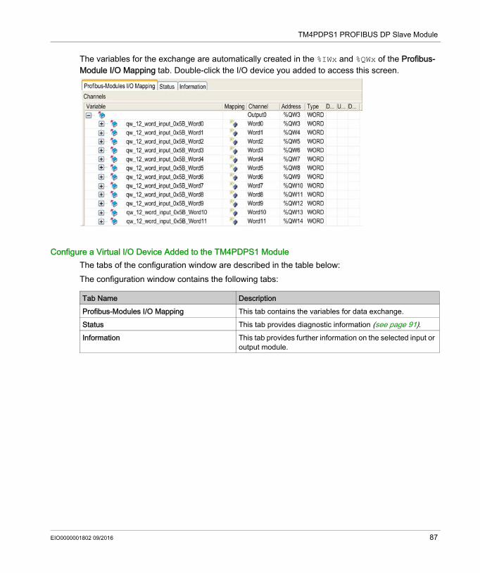
TM4PDPS1 PROFIBUS DP Slave Module
The variables for the exchange are automatically created in the %IWx and %QWx of the Profibus-Module I/O Mapping tab. Double-click the I/O device you added to access this screen.
Configure a Virtual I/O Device Added to the TM4PDPS1 ModuleThe tabs of the configuration window are described in the table below:The configuration window contains the following tabs:
Tab Name DescriptionProfibus-Modules I/O Mapping This tab contains the variables for data exchange.Status This tab provides diagnostic information (see page 91).Information This tab provides further information on the selected input or
output module.
EIO0000001802 09/2016 87
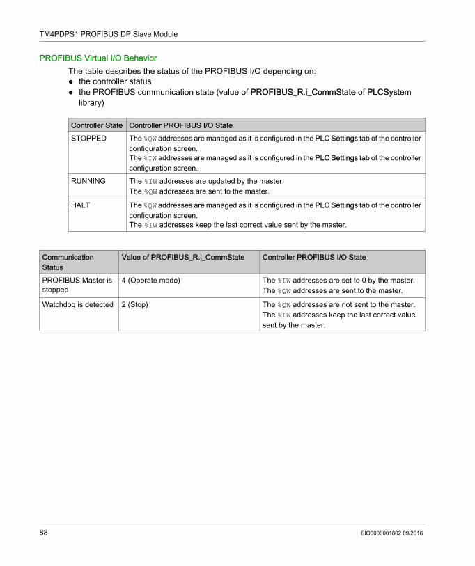
TM4PDPS1 PROFIBUS DP Slave Module
PROFIBUS Virtual I/O BehaviorThe table describes the status of the PROFIBUS I/O depending on: the controller status the PROFIBUS communication state (value of PROFIBUS_R.i_CommState of PLCSystem
library)
Controller State Controller PROFIBUS I/O StateSTOPPED The %QW addresses are managed as it is configured in the PLC Settings tab of the controller
configuration screen.The %IW addresses are managed as it is configured in the PLC Settings tab of the controller configuration screen.
RUNNING The %IW addresses are updated by the master.The %QW addresses are sent to the master.
HALT The %QW addresses are managed as it is configured in the PLC Settings tab of the controller configuration screen.The %IW addresses keep the last correct value sent by the master.
Communication Status
Value of PROFIBUS_R.i_CommState Controller PROFIBUS I/O State
PROFIBUS Master is stopped
4 (Operate mode) The %IW addresses are set to 0 by the master.The %QW addresses are sent to the master.
Watchdog is detected 2 (Stop) The %QW addresses are not sent to the master.The %IW addresses keep the last correct value sent by the master.
88 EIO0000001802 09/2016
TM4PDPS1 PROFIBUS DP Slave Module
Acyclic Exchange with PROFIBUS DPV1 Functions
IntroductionThe PROFIBUS DPV1 enhancement additionally supports acyclic data exchange between a PROFIBUS DPV1 master and DPV1 slaves. It allows access to %MW variables.
To use these functions between a PROFIBUS DPV1 master and the TM4PDPS1 module, the parameter DPV1Enable must be set to TRUE (default value) (see page 82).
Data AddressingData addressing in the logic controller is %MW.
The Profibus status of the controller must be in Operate state; therefore it can be updated even if the logic controller is not running.The %MW variables are automatically updated by the I/O driver whenever a DPV1 message is received.It is based on PROFIBUS DPV1 read and write functions. The logic address is the number of the %MW addressed.
Addressing2 different types of addressing are available for acyclic exchange:
NOTE: The following restrictions apply to direct addressing: Slot field (DU1): value 0xFF is not allowed Index field (DU2): values 0xFF, 0xE9, and 0xEA are not allowed
Addressing Type Number of Requests for Read/Write %MW Variables
Description
Direct addressing 1 The address of the %MW variable is coded directly by Slot and Index fields. See restrictions in the note below.
Indirect addressing 2 The first request sends the address of the first %MW that the master will read or write.
The second request reads or writes one or several values of the %MW variable.
EIO0000001802 09/2016 89
TM4PDPS1 PROFIBUS DP Slave Module
The table shows how to create requests for accessing the %MW from the PROFIBUS DPV1 master:
NOTE: The Length field has to have an even value (the length in byte of one %MW is 2).
Addressing DU0: DPV1 Function Number
DU1: Slot DU2: Index DU3: Length (in Bytes)
DPV1 Data Frame
1 Byte 1 Byte 1 Byte 1 Byte N ByteDirect addressing
Write 5F hex (write) MSB of the %MW address
LSB of the %MW address
Length to read
Values to write
Read 5E hex (read) MSB of the %MW address
LSB of the %MW address
Length to write
–
Indirect addressing
Send address (Step 1)
5F hex (write) 1 E9 hex 2 %MW address
Read (Step 2) 5E hex (read) 1 EA hex Length to read
–
Write (Step 2) 5F hex (write) 1 EA hex Length to write
Values to write
90 EIO0000001802 09/2016
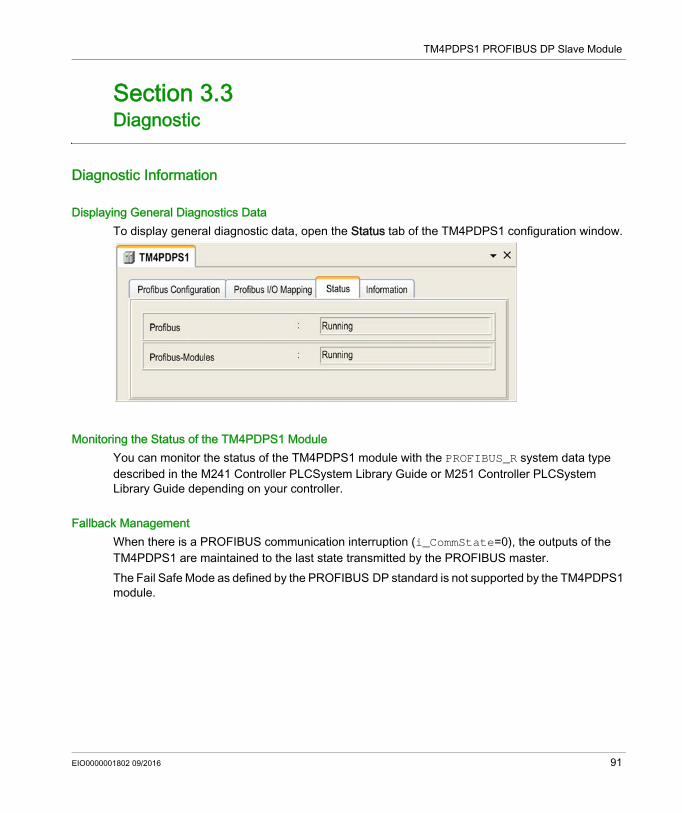
TM4PDPS1 PROFIBUS DP Slave Module
Diagnostic
Section 3.3Diagnostic
Diagnostic Information
Displaying General Diagnostics DataTo display general diagnostic data, open the Status tab of the TM4PDPS1 configuration window.
Monitoring the Status of the TM4PDPS1 ModuleYou can monitor the status of the TM4PDPS1 module with the PROFIBUS_R system data type described in the M241 Controller PLCSystem Library Guide or M251 Controller PLCSystem Library Guide depending on your controller.
Fallback ManagementWhen there is a PROFIBUS communication interruption (i_CommState=0), the outputs of the TM4PDPS1 are maintained to the last state transmitted by the PROFIBUS master.The Fail Safe Mode as defined by the PROFIBUS DP standard is not supported by the TM4PDPS1 module.
EIO0000001802 09/2016 91
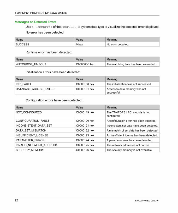
TM4PDPS1 PROFIBUS DP Slave Module
Messages on Detected ErrorsUse i_CommError of the PROFIBUS_R system data type to visualize the detected error displayed.
No error has been detected:
Runtime error has been detected:
Initialization errors have been detected:
Configuration errors have been detected:
Name Value MeaningSUCCESS 0 hex No error detected.
Name Value MeaningWATCHDOG_TIMEOUT C000000C hex The watchdog time has been exceeded.
Name Value MeaningINIT_FAULT C0000100 hex The initialization was not successful.DATABASE_ACCESS_FAILED C0000101 hex Access to data memory was not
successful.
Name Value MeaningNOT_CONFIGURED C0000119 hex The TM4PDPS1 PCI module is not
configured.CONFIGURATION_FAULT C0000120 hex A configuration error has been detected.INCONSISTENT_DATA_SET C0000121 hex Inconsistent set data have been detected.DATA_SET_MISMATCH C0000122 hex A mismatch of set data has been detected.INSUFFICIENT_LICENSE C0000123 hex An insufficient license has been detected.PARAMETER_ERROR C0000124 hex A parameter error has been detected.INVALID_NETWORK_ADDRESS C0000125 hex The network address is not correct.SECURITY_MEMORY C0000126 hex The security memory is not available.
92 EIO0000001802 09/2016
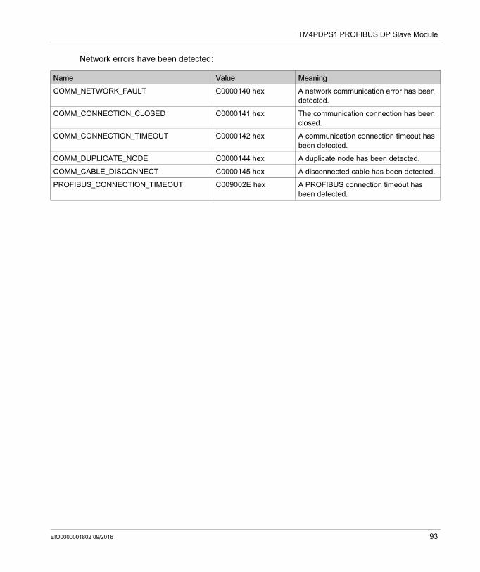
TM4PDPS1 PROFIBUS DP Slave Module
Network errors have been detected:
Name Value MeaningCOMM_NETWORK_FAULT C0000140 hex A network communication error has been
detected.COMM_CONNECTION_CLOSED C0000141 hex The communication connection has been
closed.COMM_CONNECTION_TIMEOUT C0000142 hex A communication connection timeout has
been detected.COMM_DUPLICATE_NODE C0000144 hex A duplicate node has been detected.COMM_CABLE_DISCONNECT C0000145 hex A disconnected cable has been detected.PROFIBUS_CONNECTION_TIMEOUT C009002E hex A PROFIBUS connection timeout has
been detected.
EIO0000001802 09/2016 93

TM4PDPS1 PROFIBUS DP Slave Module
94 EIO0000001802 09/2016
Modicon TM4GlossaryEIO0000001802 09/2016
Glossary
Aapplication
A program including configuration data, symbols, and documentation.
ARP(address resolution protocol) An IP network layer protocol for Ethernet that maps an IP address to a MAC (hardware) address.
BBOOTP
(bootstrap protocol) A UDP network protocol that can be used by a network client to automatically obtain an IP address (and possibly other data) from a server. The client identifies itself to the server using the client MAC address. The server, which maintains a pre-configured table of client device MAC addresses and associated IP addresses, sends the client its pre-configured IP address. BOOTP was originally used as a method that enabled diskless hosts to be remotely booted over a network. The BOOTP process assigns an infinite lease of an IP address. The BOOTP service utilizes UDP ports 67 and 68.
Cconfiguration
The arrangement and interconnection of hardware components within a system and the hardware and software parameters that determine the operating characteristics of the system.
control networkA network containing logic controllers, SCADA systems, PCs, HMI, switches, ... Two kinds of topologies are supported: flat: all modules and devices in this network belong to same subnet. 2 levels: the network is split into an operation network and an inter-controller network.These two networks can be physically independent, but are generally linked by a routing device.
controllerAutomates industrial processes (also known as programmable logic controller or programmable controller).
EIO0000001802 09/2016 95
Glossary
Ddevice network
A network that contains devices connected to a specific communication port of a logic controller. This controller is seen as a master from the devices point of view.
DHCP(dynamic host configuration protocol) An advanced extension of BOOTP. DHCP is more advanced, but both DHCP and BOOTP are common. (DHCP can handle BOOTP client requests.)
DNS(domain name system) The naming system for computers and devices connected to a LAN or the Internet.
EEDS
(electronic data sheet) A file for fieldbus device description that contains, for example, the properties of a device such as parameters and settings.
EtherNet/IP(Ethernet industrial protocol) An open communications protocol for manufacturing automation solutions in industrial systems. EtherNet/IP is in a family of networks that implement the common industrial protocol at its upper layers. The supporting organization (ODVA) specifies EtherNet/IP to accomplish global adaptability and media independence.
expansion busAn electronic communication bus between expansion I/O modules and a controller.
FFTP
(file transfer protocol) A standard network protocol built on a client-server architecture to exchange and manipulate files over TCP/IP based networks regardless of their size.
II/O
(input/output)
ICMP(Internet control message protocol) Reports errors detected and provides information related to datagram processing.
96 EIO0000001802 09/2016
Glossary
IP(Internet protocol Part of the TCP/IP protocol family that tracks the Internet addresses of devices, routes outgoing messages, and recognizes incoming messages.
LLSB
(least significant bit/byte) The part of a number, address, or field that is written as the right-most single value in conventional hexadecimal or binary notation.
MMAC address
(media access control address) A unique 48-bit number associated with a specific piece of hardware. The MAC address is programmed into each network card or device when it is manufactured.
MIB(management information base) An object database that is monitored by a network management system like SNMP. SNMP monitors devices are defined by their MIBs. Schneider Electric has obtained a private MIB, groupeschneider (3833).
MSB(most significant bit/byte The part of a number, address, or field that is written as the left-most single value in conventional hexadecimal or binary notation.
Nnode
An addressable device on a communication network.
PProfibus DP
(Profibus decentralized peripheral) An open bus system uses an electrical network based on a shielded 2-wire line or an optical network based on a fiber-optic cable. DP transmission allows for high-speed, cyclic exchange of data between the controller CPU and the distributed I/O devices.
programThe component of an application that consists of compiled source code capable of being installed in the memory of a logic controller.
protocolA convention or standard definition that controls or enables the connection, communication, and data transfer between 2 computing system and devices.
EIO0000001802 09/2016 97
Glossary
RRPI
(requested packet interval) The time period between cyclic data exchanges requested by the scanner. EtherNet/IP devices publish data at the rate specified by the RPI assigned to them by the scanner, and they receive message requests from the scanner with a period equal to RPI.
SSNMP
(simple network management protocol) A protocol that can control a network remotely by polling the devices for their status and viewing information related to data transmission. You can also use it to manage software and databases remotely. The protocol also permits active management tasks, such as modifying and applying a new configuration.
TTCP
(transmission control protocol) A connection-based transport layer protocol that provides a simultaneous bi-directional transmission of data. TCP is part of the TCP/IP protocol suite.
UUDP
(user datagram protocol) A connectionless mode protocol (defined by IETF RFC 768) in which messages are delivered in a datagram (data telegram) to a destination computer on an IP network. The UDP protocol is typically bundled with the Internet protocol. UDP/IP messages do not expect a response, and are therefore ideal for applications in which dropped packets do not require retransmission (such as streaming video and networks that demand real-time performance).
98 EIO0000001802 09/2016
Modicon TM4IndexEIO0000001802 09/2016
Index
Aacyclic exchange, 89
Ccyclic data exchanges, generating EDS file for, 46cyclic exchange, 86
Ddiagnostic information, 91DPV1
PROFIBUS functions, 89
EEDS file, generating, 46EtherNet
EtherNet/IP device, 45Ethernet
FTP Server, 42Modbus TCP Server/Client, 28Modbus TCP slave device, 63Services, 21SNMP, 44Web server, 30
expansion modulesadding, 15configuration, 15
FFTP Server
Ethernet, 42
MModbus
Protocols, 28
EIO0000001802 09/2016
Modbus TCP Server/ClientEthernet, 28
PProtocols, 21
IP, 23Modbus, 28
protocolsSNMP, 44
SSNMP
Ethernet, 44protocols, 44
WWeb server
Ethernet, 30
99

Index
100 EIO0000001802 09/2016