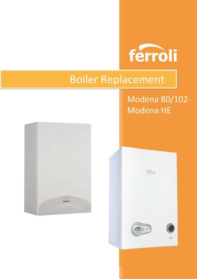
modena 80/102- modena he
TRANSCRIPT
ferroli
Boiler Replacement
Modena 80/102- Modena HE
BOILER REPLACEMENT: MODENA 80/102 TO MODENA C HE
The Installation must comply with the following;
Gas Safety (Installation & Use) Regulations
The Building Regulations
The Building Regulations (Scotland)
Building Regulations (Northern Ireland)
The Water Fittings Regulations or Water Byelaws in Scotland
The Current I.E.E. Wiring Regulations -------------------------------------------------------
BS 5440: Part 1 - Flues.
BS 5440: Part 2 - Ventilation.
BS 6798 - Installation of gas fired hot water boilers
BS 7671: - Electrical wiring
BS 6891 - Gas Installation
BS 5546 - Installation of hot water supplies for domestic purposes.
BS 5449 - Forced circulation hot water systems
BS 7074 - Expansion vessels / sealed systems
BS 7593 - Treatment of water in domestic central heating systems.
Introduction
The new Ferroli Modena C HE high efficiency condensing combination boiler is an ideal replacement
for the earlier non-condensing Modena 80E or Modena 102.
The new Ferroli Modena C HE is smaller, weighs less, has built-in frost protection and an IP
protection rating of IPX5D. This allows direct replacement wherever the existing boiler is legitimately
installed (i.e. Kitchen, Garage, Bathroom, etc.)
Although the actual position of the pipe-work connections differ slightly, the configuration remains
the same, thereby requiring only limited pipe-work alteration.
The electrical connection remains the same, i.e. all models supplied with a factory fitted three core
fly - lead to provide a permanent live connection and all models use the same volt free contacts for
any external system controls.
This guide refers to the fitting of a replacement boiler with a standard horizontal flue application only (minor adjustments may be necessary for other flue applications – refer to boiler installation instructions)
The flue outlet connection on the new Modena C HE is centrally aligned and is therefore completely compatible with the earlier Modena 102. The flue connection on the Modena 80E is to the left of centre but providing that there is a minimum clearance of 35mm to the left of the existing boiler, no alteration to the existing flue position is necessary.
-----------------------------------------------------------------------------------------------------------------------------
Please note:
As with all condensing boilers it is necessary to check the existing flue terminal position to ensure that the “plume” from the combustion products will not create a ‘nuisance problem’.
A plume displacement kit is available to overcome any such problems.
Consideration must also be given for the provision of a
condensate outlet for the new boiler.
The work procedures described in this document must
be completed strictly in accordance with the
manufacturer’s installation instructions, current
regulations and relevant standards, and only by
competent person/persons as stated in the Gas Safety
(Installation & Use) Regulations.
Prior to fitting the replacement boiler the entire system
must be thoroughly cleansed and flushed in accordance
with Building Regulations L1A/L1B & BS 7593.
BOILER REPLACEMENT: MODENA 80/102 TO MODENA C HE
Fig.1
Manual Handling
When lifting take suitable safety precautions: keep your back straight, bend knees, do not turn your
body, avoid bending forward or sideways and keep the load as close as possible to your body. Ideally
seek assistance in lifting the boiler.
If possible, use a trolley or other suitable means to carry the boiler to site. Use appropriate
protective clothing and gloves to avoid injury from any sharp edges etc.
------------------------------------------------------------------------------------------------------------------------------------ REMOVE THE EXISTING MODENA 80/102
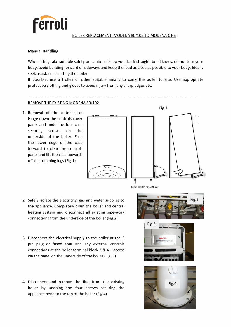
1. Removal of the outer case:
Hinge down the controls cover
panel and undo the four case
securing screws on the
underside of the boiler. Ease
the lower edge of the case
forward to clear the controls
panel and lift the case upwards
off the retaining lugs (Fig.1)
2. Safely isolate the electricity, gas and water supplies to
the appliance. Completely drain the boiler and central
heating system and disconnect all existing pipe-work
connections from the underside of the boiler (Fig.2)
3. Disconnect the electrical supply to the boiler at the 3
pin plug or fused spur and any external controls
connections at the boiler terminal block 3 & 4 – access
via the panel on the underside of the boiler (Fig. 3)
4. Disconnect and remove the flue from the existing
boiler by undoing the four screws securing the
appliance bend to the top of the boiler (Fig.4)
Case Securing Screws
Fig.2
Fig.3
Fig.4
BOILER REPLACEMENT: MODENA 80/102 TO MODENA C HE
Boiler Pack Contents
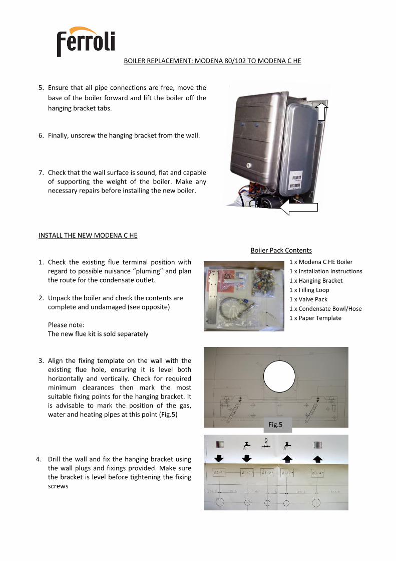
5. Ensure that all pipe connections are free, move the
base of the boiler forward and lift the boiler off the
hanging bracket tabs.
6. Finally, unscrew the hanging bracket from the wall.
7. Check that the wall surface is sound, flat and capable
of supporting the weight of the boiler. Make any necessary repairs before installing the new boiler.
INSTALL THE NEW MODENA C HE 1. Check the existing flue terminal position with
regard to possible nuisance “pluming” and plan the route for the condensate outlet.
2. Unpack the boiler and check the contents are complete and undamaged (see opposite)
Please note: The new flue kit is sold separately
3. Align the fixing template on the wall with the
existing flue hole, ensuring it is level both horizontally and vertically. Check for required minimum clearances then mark the most suitable fixing points for the hanging bracket. It is advisable to mark the position of the gas, water and heating pipes at this point (Fig.5)
4. Drill the wall and fix the hanging bracket using the wall plugs and fixings provided. Make sure the bracket is level before tightening the fixing screws
1 x Modena C HE Boiler
1 x Installation Instructions
1 x Hanging Bracket
1 x Filling Loop
1 x Valve Pack
1 x Condensate Bowl/Hose
1 x Paper Template
Fig.5
BOILER REPLACEMENT: MODENA 80/102 TO MODENA C HE
Fig.6
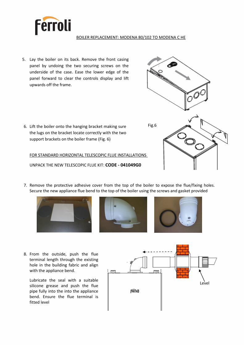
5. Lay the boiler on its back. Remove the front casing
panel by undoing the two securing screws on the
underside of the case. Ease the lower edge of the
panel forward to clear the controls display and lift
upwards off the frame.
6. Lift the boiler onto the hanging bracket making sure
the lugs on the bracket locate correctly with the two
support brackets on the boiler frame (Fig. 6)
FOR STANDARD HORIZONTAL TELESCOPIC FLUE INSTALLATIONS
UNPACK THE NEW TELESCOPIC FLUE KIT: CODE - 041049G0
7. Remove the protective adhesive cover from the top of the boiler to expose the flue/fixing holes. Secure the new appliance flue bend to the top of the boiler using the screws and gasket provided
8. From the outside, push the flue terminal length through the existing hole in the building fabric and align with the appliance bend.
Lubricate the seal with a suitable silicone grease and push the flue pipe fully into the into the appliance bend. Ensure the flue terminal is fitted level
Level

BOILER REPLACEMENT: MODENA 80/102 TO MODENA C HE
9. It is suggested that where possible the existing pipe-work is cut back approximately 200mm - 300mm for ease of connecting the existing pipe-work to the new valves (Fig 8)
If a stand-off bracket has been used and the pipe-work runs behind the boiler, then a new stand-off bracket will need to be fitted and pipes extended to the position previously marked. (paragraph 3.)
10. Remove the condensate bowl and hose from the boiler fittings pack. Undo plastic nut (Fig.9-A) and fit the condensate bowl and washer. Push on the rubber condensate hose to the trap outlet (Fig.9-B).
11. Connect the safety valve outlet (Fig.9-C) to the existing 15mm pipe and then connect the condensate pipe to the rubber hose outlet. Check that both terminate in accordance with – BS 6798. Take care not to interfere with the new routes for gas, water and heating pipe connections
12. Fit the valve kit to the connections on the underside of the boiler using the washers provided (Fig 10) and reconnect to the existing pipe-work.
A CH FLOW B HOTWATER OUTLET C GAS D COLD WATER INLET F CH RETURN
Fig 10
Cut existing pipes back
approx 200mm – 300mm
Fig.8
Fig.9
A B C
Condensate bowl,
washer and rubber
hose connection
BOILER REPLACEMENT: MODENA 80/102 TO MODENA C HE
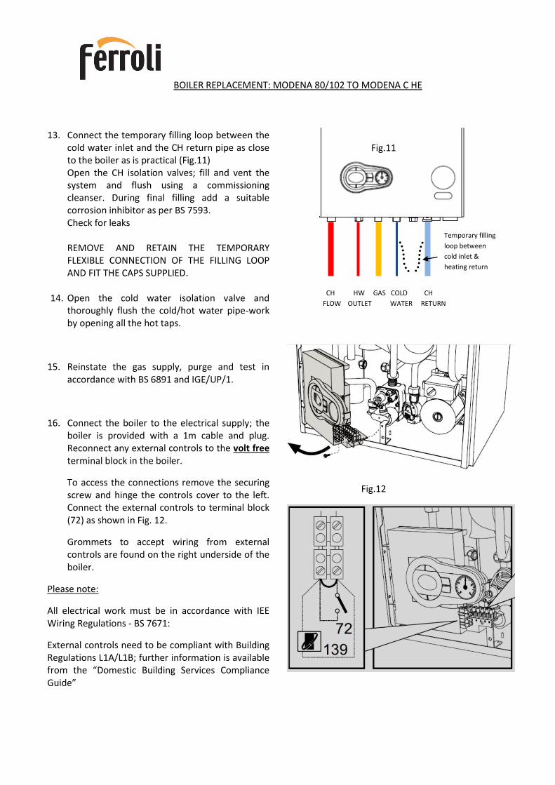
13. Connect the temporary filling loop between the
cold water inlet and the CH return pipe as close to the boiler as is practical (Fig.11) Open the CH isolation valves; fill and vent the system and flush using a commissioning cleanser. During final filling add a suitable corrosion inhibitor as per BS 7593. Check for leaks REMOVE AND RETAIN THE TEMPORARY FLEXIBLE CONNECTION OF THE FILLING LOOP AND FIT THE CAPS SUPPLIED.
14. Open the cold water isolation valve and thoroughly flush the cold/hot water pipe-work by opening all the hot taps.
15. Reinstate the gas supply, purge and test in accordance with BS 6891 and IGE/UP/1.
16. Connect the boiler to the electrical supply; the boiler is provided with a 1m cable and plug. Reconnect any external controls to the volt free terminal block in the boiler.
To access the connections remove the securing screw and hinge the controls cover to the left. Connect the external controls to terminal block (72) as shown in Fig. 12.
Grommets to accept wiring from external controls are found on the right underside of the boiler.
Please note:
All electrical work must be in accordance with IEE Wiring Regulations - BS 7671:
External controls need to be compliant with Building Regulations L1A/L1B; further information is available from the “Domestic Building Services Compliance Guide”
CH HW GAS COLD CH
FLOW OUTLET WATER RETURN
Temporary filling
loop between
cold inlet &
heating return
Fig.11
Fig.12

BOILER REPLACEMENT: MODENA 80/102 TO MODENA C HE
Fig.13
Fig.14
Fig. 15
Sample points: 1 = Air / 2 = Flue Gas
17. Commissioning the boiler:
(See 3.3 of the Modena C HE Installation Instructions)
Connect a manometer to the inlet test point of the gas valve (Fig.13) Set the boiler to operate at maximum by selecting ‘TEST MODE’ and check that the operational (working) pressure at the gas inlet pressure test point is 20 mbar. A pressure of 20 mbar should be obtained with all other gas appliances operating.
To enter and exit ‘TEST MODE’, press the CH + & - buttons simultaneously for 5 seconds (Fig.14)
Please note: there may be a pressure loss across the isolation valve to the gas valve inlet test point of up to 1.3 mbar at maximum.
Remove the manometer & re-tighten the inlet test point.
18. Measure the gas rate of the boiler and check against the following table;
19. Connect the flue gas analyser to the flue sample point (Fig.15); with the boiler still in TEST MODE check that the readings are within the tolerances set out in the table below;
If the readings are satisfactory, replace the boiler front cover.
Test the correct operation of the boiler, central heating system and DHW.
Advise the customer on the operation of the new boiler and any new controls.
Complete the “Benchmark Log Book
ferroli
Ferroli Limited
Lichfield Road
Branston Industrial
Estate Burton on Trent
DE14 3HD
www.ferroli.co.uk
Boiler replacement
Calls to the above numbers are charged at national rate from BT landlines. Calls from mobile networks may be considerably more.Whilst every effort is taken to ensure the accuracy of the information contained within the brochure, the details are offered in good faith and Ferroli Ltd. accepts no liability for matters arising as a result of errors and/or omissions. The information in this brochure was correct at the time of printing, however specifications and designs may be changed owing to Ferroli’s policy of continuous product research and development. The technical specifications in the product instruction manual supersedes and should always be referred to during installation and maintenance. Reproduction of this publication, or any part, is not permitted without the written consent of Ferroli Ltd at [email protected]. The statutory rights of the consumer are not affected.
CONTACT US IN THE UK
SALES 0843 479 [email protected]
SERVICE AND TECHNICAL 0843 479 0479 [email protected]@ferroli.co.ukGENERAL ENQUIRIES
0843 479 0009 [email protected]
TWITTERtwitter.com/ferroliuk
Training Well trained installers are the key to a safe and efficient heating system. We offer a choice of training and product awareness courses on our key product range, including the Modena HE, at Ferroli’s fully equipped training centre in Burton-upon-Trent and at specialist training locations across the UK. Courses are aimed at engineers of all levels to ensure that everyone comes away with the skills and knowledge needed to deliver the first class service that customers expect and deserve. For more details visit www.ferroli.co.uk/training or ring 0843 479 0009.
Ferroli Domestic Boilers Offering gas wall mounted units with outputs of up to 50kW, Ferroli’s stylish, compact domestic boilers provide maximum comfort with minimal fuel usage. With a choice of conventional, condensing and combi technologies, there’s a boiler to match the heating and hot water requirements of every home.
Ferroli Commercial and Industrial Boilers Ferroli commercial boilers for pressure jet oil, forced air gas or dual fuel are factory matched with high efficiency burners to provide outputs of up to 12,350kW, whilst meeting the strictest emissions demands.
Ferroli Spares The popularity of Ferroli as first choice for both domestic and commercial installations means that heating parts stockists offer readily available spares for Ferroli boilers. Ferroli has a UK-based fully stocked warehouse enabling same-day despatch of just about any part needed to keep your Ferroli boiler running.
Modena 80/102- Modena HE