modelling low energy electron and positron tracks in ... · modelling low energy electron and...
TRANSCRIPT
Eur. Phys. J. D (2013)DOI: 10.1140/epjd/e2013-40276-1
Colloquium
THE EUROPEANPHYSICAL JOURNAL D
Modelling low energy electron and positron tracks in biologicallyrelevant media
Francisco Blanco1, Antonio Munoz2, Diogo Almeida3, Filipe Ferreira da Silva3, Paulo Limao-Vieira3,Martina C. Fuss4, and Ana G. Sanz4, Gustavo Garcıa4,5,a
1 Departamento de Fısica Atomica, Molecular y Nuclear, Universidad Complutense de Madrid, 28040 Madrid, Spain2 Centro de Investigaciones Energeticas Medioambientales y Tecnologicas, Avenida Complutense 22, 28040 Madrid, Spain3 Laboratorio de Colisoes Atomicas e Moleculares, CEFITEC, Departamento de Fısica, Faculdade de Ciencias e Tecnologia,
Universidade Nova de Lisboa, 2829-516 Caparica, Portugal4 Instituto de Fısica Fundamental, Consejo Superior de Investigaciones Cientıficas, Serrano 113-bis, 28006 Madrid, Spain5 Centre for Medical Radiation Physics, University of Wollongong, 2522 NSW, Australia
Received 30 April 2013 / Received in final form 29 July 2013Published online (Inserted Later) – c© EDP Sciences, Societa Italiana di Fisica, Springer-Verlag 2013
Abstract. This colloquium describes an approach to incorporate into radiation damage models the effect oflow and intermediate energy (0–100 eV) electrons and positrons, slowing down in biologically relevant ma-terials (water and representative biomolecules). The core of the modelling procedure is a C++ computingprogramme named “Low Energy Particle Track Simulation (LEPTS)”, which is compatible with availablegeneral purpose Monte Carlo packages. Input parameters are carefully selected from theoretical and ex-perimental cross section data and energy loss distribution functions. Data sources used for this purposeare reviewed showing examples of electron and positron cross section and energy loss data for interactionswith different media of increasing complexity: atoms, molecules, clusters and condense matter. Finally, weshow how such a model can be used to develop an effective dosimetric tool at the molecular level (i.e.nanodosimetry). Recent experimental developments to study the fragmentation induced in biologicallymaterial by charge transfer from neutrals and negative ions are also included.
1 Introduction
Advanced uses of radiation in radiotherapy, as ion beamcancer therapy [1,2] and targeting nanoparticles to en-hance radiation effects [3,4], as well as in radiodiagnos-tic procedures like PET (Positron Emission Tomography)scanning, are demanding radiation interaction models atthe molecular level including the effect of any generatedsecondary particles. At this level, low energy secondaryelectrons are now recognized as being the main instigatorfor radiation induced damage [5–8].
Traditional dosimetry for radiotherapy is based on theenergy deposited by the radiation per mass unit (absorbeddose), which provides a macroscopic description of radia-tion effects. Some years ago, in order to increase the levelof detail of this description, microdosimetry was developedby redefining radiation representative parameters, as re-ported in reference [9]. Although this formalism allowedone to characterise radiation effects in microvolumes, typ-ically of the size of a living cell, microdosimetric param-eters are still based on the absorbed dose. More recently,aiming to describe the effect of radiation at the nanoscale,typically the size of DNA helix segments, the concept of
a e-mail: [email protected]
nanodosimetry has been introduced. A first attempt totypify radiation damage in nanovolumes was carried outby Grosswendt [10], by proposing the size of ionizationcluster distribution in a nanovolume, of about 50 nm3,as an indicator of the induced damage to DNA. This isclearly a better approach to characterise radiation dam-age at the molecular level, than simply the energy de-position, but it only accounts for damage produced byionizing particles. No dissociations induced by electronicand vibrational excitations of the molecule or electron at-tachment are included and, as mentioned above, these lowenergy processes are the most efficient to produce bond-breaking in biomolecular systems. Therefore, further infor-mation about induced fragmentation patterns is requiredto evaluate radiation damage at the nanoscale. In addi-tion, no equilibrium about energy deposition can be as-sumed in these nanovolumes as they are usually placed inlow dose penumbra and boundary regions where conven-tional dosimetry is not applicable. Transport of secondaryspecies from high-dose irradiated areas thus needs to beprecisely simulated, so that accurate energy and angulardistribution functions for those species interacting withthe medium are required.
On the other hand, positrons have become importantsubjects to study as their interactions with biomolecular

Page 2 of 18
systems are the basis of positron emission tomography(PET scanning). Attaching positron emitters to appropri-ate molecular tracers and mapping positron annihilationconcentrations in the target is currently one of the mostpowerful tools to detect early tumour activities or predict-ing some brain diseases such as Alzheimer. More recently,PET techniques have also been used as a complement ofion beam cancer treatments for dosimetry purposes. Inparticular the passage of fast ions through biological ma-terial activates positron emitters (11C, 15O), which can beused as indicators for radiation dosimetry by employingPET imaging techniques.
Finally, another important objective of radiation mod-els at the molecular level is to consider the role of radi-cals, both charged and neutral, that can generate indirectdamage by charge transfer or reactive mechanisms whichfinally lead to structural changes in the biomolecularsystems.
This article reviews the procedures we followed duringthe last few years in order to develop a simulation tool,based on a physical approach to the scattering and en-ergy transfer processes which are crucial at the end of theradiation tracks, where low energy secondary species aredominant, to determine radiation damage in terms of bondbreaking and induced molecular dissociations. The partic-ular subjects of this study are electrons, positrons and rad-icals interacting with biologically relevant molecules (wa-ter and structural components of DNA and RNA). Theeffects of introducing some radiosensitizers, as nanopar-ticles [3,4], to enhance secondary electron generation willbe also analysed, in terms of providing an approach to in-corporate them into the model. Finally, our recent exper-imental studies on anionic fragmentation of biomolecules,by charge transfer processes, will be summarized. Thesegive some indications of how to introduce indirect radicaleffects in radiation damage models at the molecular level.
2 Input data requirements and sourcesfor electrons and positrons
Modelling single electron and positron tracks in biolog-ically relevant media requires an important amount ofscattering data, in terms of cross section and energy loss.The structure of the tracks is defined by a combinationof integral and differential scattering cross sections to-gether with the energy transferred in the single scatter-ing events. These data would be needed for a wide en-ergy range from almost zero (thermal energies) up to thehigh energy of the primary beam radiation, typically inthe domain of the MeVs for applications in radiother-apy. Fortunately, biomolecular media are mainly consti-tuted by relatively light atoms (H, C, N, O) for whichelectron and positron scattering can be accurately de-scribed, even for elastic processes [11–13], in terms ofthe first Born approximation [14,15] for incident energiesabove 10 keV. For these energies, all the required scat-tering information can be derived from the correspond-ing Bethe surfaces [15]. For this reason, we will focus our
experimental and theoretical procedures to derive scat-tering cross section and energy loss data for electrons andpositrons interacting with water and other biologically rel-evant molecules (tetrahydrofuran-THF, pyrimidine, DNAand RNA bases) for incident energies below 10 keV.
2.1 Electron and positron scatteringcross section calculations
Electron scattering cross sections from molecular tar-gets have been calculated for several decades, by usingdifferent methods with different degrees of sophistica-tion when representing the target properties. Ab initiomethods, based on a quantum description of the molec-ular target states followed by a dynamical study of thescattering equations including correlation and other ef-fects, depending on the actual approach, can be con-sidered the most accurate. Amongst them the R-matrixapproach [16,17], symmetry-adapted single-centre expan-sion [18], and Schwinger multichannel procedures [19], canbe highlighted. Each method has its particular limitationsfor the covered energy range, and type or size of targetto be treated, with an update of the most representativetechniques being found in reference [20]. In this contextwe clearly found that a general approach covering reason-ably well a broad energy range and able to link with someof these previously mentioned methods, where they areapplicable, needs to be developed for modelling purposes.The procedure we are proposing here is based on an inde-pendent atom representation of the molecule [21]. Conse-quently, only when the incident energy is high enough, toensure that the scattering cross sections for a given atomdo not interfere with those of the surrounding atoms, canwe consider this approach as valid. This validity limit de-pends on the atoms constituting the target but in general,for those considered here, we can assume that for ener-gies above 100 eV the independent atom model (IAM) isa good approximation (see comparison with experimentsfor different molecules in [22]). For lower energies, we pro-posed a simple procedure based on the calculation of theoverlap of the atomic cross sections according to their po-sitions in the molecule. Sequential details on the calcula-tion method we developed, to obtain electron and positronscattering cross sections from atoms, molecules, clustersand condensed matter, over a broad energy range, typi-cally 30–10 000 eV, will be given in the next subsections.Note that our calculation is averaged over all incident an-gles and therefore effects depending on the direction ofapproach of the incoming projectile are not considered.
2.1.1 Cross section calculations for electron and positronscattering from atoms
The first step to develop a general scattering calculationframework for electrons and positrons, based on inde-pendent atom representations, is to describe interactionswith atomic targets as accurately as possible (within thelimitation imposed by the considered energy range). For

Page 3 of 18
this purpose, we represent scattering from atoms by aninteracting complex potential (i.e. the optical potential):
Vopt(r) = V (r) + iV a(r) (1)
whose real part, V (r), accounts for the elastic scatter-ing of the incident electrons/positrons, while the imagi-nary part, V a(r), represents the inelastic processes thatare considered as “absorptions” from the incident beam.
For electron scattering, to construct this complex po-tential for each atom, the real part of the potential is repre-sented by the sum of three terms: (i) a static term derivedfrom a Hartree-Fock calculation of the atomic charge dis-tribution [23], (ii) an exchange term to account for the in-distinguishability of the incident and target electrons [24]and (iii) a polarisation term [25] for the long-range interac-tions which depend on the target dipole polarisability [26].The imaginary part, following the procedure of Staszewskaet al. [27], then treats inelastic scattering as electron-electron collisions. However we initially found some ma-jor discrepancies in the available scattering data, whichwere subsequently corrected when a physical formulationof the absorption potential [28,29] was introduced. Fur-ther improvements to the original formulation, such asthe inclusion of screening effects, local velocity correctionsand in the description of the electrons’ indistinguishabil-ity [30], finally led to a model that provides a good approx-imation of electron-atom scattering over a broad energyrange [22,31]. An excellent recent example of this was forelastic electron-atomic iodine scattering [32], where theoptical potential results compared very favourably withthose from a highly sophisticated Dirac-B-spline R-matrixcomputation.
Concerning positron scattering from atoms, we used anadapted version of the above optical potential. Now, thereal part has only two terms: (i) a static potential derivedfrom a standard Hartree–Fock calculation of the atomiccharge density, following a similar procedure to that pro-posed by Reid and Wadhera [33–35]; and (ii) the polariza-tion potential. As exchange does not apply in this case, lowenergy positron elastic scattering cross sections generallytend to be lower in value compared to those for the cor-responding electron scattering cases. Concerning the po-larisation term, initial calculations from Zhang et al. [36]used a simple asymptotic expression proportional to thetarget polarisabilty but introducing a corrective parame-ter for short distances. However, as this term gives the onlyattractive contribution to the positron scattering calcula-tions, it becomes relatively more relevant than for electronscattering. For this reason we have derived a new polar-isation potential based on that proposed by McEachranet al. [37] for noble gases, by scaling with a constant pa-rameter to diffuse the charge density of each target orbitalwhich in turn leads to the appropriate dipole polarisabilityfor the target (see Ref. [38] for details). For the imagi-nary part, i.e. the absorption potential which accounts forthe inelastic processes, we used initially the scheme pro-posed in references [33–35], based on Staszewska’s proce-dure [27] for electron scattering, which considers inelasticprocesses as binary collisions between the incident par-ticles and a “quasi-free” electron cloud representing the
target electrons. The most controversial part of this po-tential is the procedure to define the threshold energy (Δ),in order to initiate the absorption process (see Blanco andGarcıa [28–30] for details). As far as the inelastic crosssections are concerned, the main difference between elec-tron and positron scattering is the positronium formationchannel. Consistent with the foundations of our approach,the threshold energy (Δ) should be the energy of the firstexcited level. For electron-atom scattering it should thusbe the energy of the lowest excited electronic state (Eres).However, around this threshold energy, an important lim-itation of this method may arise for positrons. Indeed,at these energies, positronium formation is a dominantinelastic channel which cannot be explained in terms ofbinary collisions [39], and therefore was not included inthe original formulation of the absorption potential. Thethreshold for positronium formation (Δp) is 6.8 eV belowthe ionisation limit of all the species in question, whichnormally results in an energy which is less than that forthe first discrete excited level. For this reason, Reid andWadehra [33–35] proposed to use the threshold energyfor positronium formation as the absorption threshold pa-rameter (Δ = Δp) (i.e. a semi-empirical approach). Thisprocedure was initially considered as an indirect way of in-troducing positronium formation into the absorption po-tential, and indeed some agreement with the then availableexperimental data was found for the noble gases. However,as we have recently noticed in argon [38], it is an experi-mentally evident fact that positronium formation actuallyoccurs over a relatively narrow energy range, namely fromthreshold up to about 100 eV. Contrary to this, the effectproduced by lowering the absorption potential thresholdextends over the whole energy range. This means that bysimply lowering the absorption threshold we are probablyoverestimating the total cross section at the higher ener-gies. In fact, positronium formation at these energies canbe considered as a doubly-binary collision process. Apartfrom the binary collision with a target electron, which canbe accounted for the original absorption potential, it re-quires an additional positron or electron scattering off theresidual ion [39]. This situation makes it difficult to in-troduce positronium formation as an independent inelas-tic process. By taking these considerations into accountwe proposed to adopt a compromise solution, by definingan energy-dependent parameter for the absorption thresh-old [40]:
Δ (E) = Δe − (Δe − Δp)e−
(E−Δp
Em
), (2)
where Δe is the lowest excitation energy of the atomic tar-gets, Δp is the Ps formation threshold and Em is a charac-teristic energy at which the inelastic cross section, withoutpositronium formation, reaches its maximum (generallyplaced in Em = 20 eV [40]). This expression provides val-ues between the limit conditions: Δ(E) = Δp for energiesclose to the Ps formation threshold and Δ(E) = Δe forhigher energies. A smooth transition between both limitsis modulated by the negative exponential and governed bythe Em parameter [40].

Page 4 of 18
2.1.2 Cross section calculations for electron and positronscattering from molecules
In order to obtain molecular cross sections, the indepen-dent atom model (IAM) has been followed by applying acoherent addition procedure, commonly known as the ad-ditivity rule (AR). In this approach, the molecular scatter-ing amplitude (F (θ)) is derived from the sum of the aboveatomic amplitudes which lead to the differential elasticcross section for the molecule (dσmolec/dΩ), according to
F (θ) =∑
atoms
fi(θ)eiq.ri ;
dσmoleculeel
dΩ=
∑i,j
fi (θ) f∗j (θ)
sin qrij
qrij , (3)
where q is the momentum transferred in the scatteringprocess and rij is the distance between the ith and jthatoms.
Integral elastic cross sections for the molecule canthen be determined by integrating equation (1). Alter-natively, elastic cross sections can be derived from theatomic scattering amplitudes in conjunction with theoptical theorem [30] giving:
σmoleculeel =
∑atoms
σatomel . (4)
Unfortunately, in its original form, we found an inherentcontradiction between the integral cross section derivedfrom those two approaches, which suggested that the op-tical theorem was being violated [41]. This, however, wasresolved using a normalisation technique so that integralcross sections determined from the two methods are nowentirely consistent.
The main limitation of the AR is that no molecularstructure is considered, thus it is really only applicablewhen the incident electrons are fast enough to effectively“see” the target molecule as a sum of the individual atoms(typically above ∼100 eV). To reduce this limitation wedeveloped the SCAR method [22,31], which considers thegeometry of the corresponding molecule (atomic positionsand bond lengths) by introducing some screening coeffi-cients which modify both the differential and integral crosssections, especially for lower energies [22,31],
σelast =∑
i
siσelasti (5)
where si are the screening coefficients which account forthe geometrical overlapping of the atoms. Their valuesare within the range 0 � si � 1, so that they reduce thecontribution from each atom to the total cross section.To generate these coefficients is required only data on theposition and the total cross section σi of each atom in themolecule,
si = 1 − ε(2)i
2!+
ε(3)i
3!− ε
(4)i
4!+ . . . ± ε
(N)i
N !, (6)
ε(k)i
∼= N − k + 1N − 1
∑j( �=i)
σjε(k−1)j
αij(k = 2, . . . , N) (7)
where N accounts for the number of atoms in the targetmolecule, the j index runs over all the N atoms, exceptthe atom i, and αij = max(4πr2
ij , σi, σj) being rij thedistance between the atoms i and j (a detailed discussionis given in [22,31]).
With this correction the range of validity of the IAM-SCAR method might be extended down to about 30 eV.For intermediate and high energies (30–10 000 eV) our ap-proach has been proven to be a powerful tool to calculateelectron scattering cross sections from a high variety ofmolecules of very different sizes, from diatomic to com-plex biomolecules [31,42]. For positron scattering, how-ever, further studies are needed in order to establish thelower energy limit of the IAM-SCAR method.
From the above description of the IAM-SCAR proce-dure, it is obvious that vibrational and rotational exci-tations are not considered in this calculation. However,for polar molecules additional dipole-induced excitationcross sections can be calculated following the proceduresuggested by Jain [43]. Basically it calculates differentialand integral rotational excitation cross sections for a freeelectric dipole in the framework of the first Born approx-imation (FBA) which can be incorporated into our IAM-SCAR calculation in an incoherent way by just addingthe results as an independent channel. Although rota-tional excitation energies are, in general, very small (typ-ically a few meV) in comparison with the incident elec-tron energies, in order to validate the Born approximationthe latter energies should be higher than a few eVs. Un-der these circumstances, rotational excitation cross sec-tions J → J ′ were calculated by weighting the popula-tion for the Jth rotational quantum number at 300 Kand estimating the average excitation energy from thecorresponding rotational constants. A unique transitionstarting from this J averaged state with ΔJ = 1 is thenconsidered. We can label this whole procedure as the IAM-SCAR + Rotations method and it has been successfullyused for polar molecules such as H2O, pyrimidine, HCNand α-tetrahydrofurfuryl alcohol (THFA) [44–47].
Additionally, when the permanent dipole moment ofthe molecule in question is very large, the FBA also failsfor medium and large scattering angles. In order to par-tially solve this, we introduced a correction based onthat suggested by Dickinson [48], which brings a substan-tial improvement of the electron scattering cross sectionsfor strongly polar molecules. This procedure introduces afirst-order corrective term to the differential cross sections(
dσDck
dΩ
), for medium and large angles but maintains the
FBA result(
dσB
dΩ
)for the lower angles:
dσB
dΩ≈ μ2
6Ei
1sin2(θ/2)
θ < θc, (8)
dσDck
dΩ≈ πμ
64Ei
1sin3(θ/2)
θ > θc, (9)
where μ stands for the permanent dipole moment of themolecule and Ei the energy of the projectile. Providingthat the dipole moment is larger than μ = 0.75 Dy, both

Page 5 of 18
curves smoothly join together at θc, the critical angle atwhich they cross each other.
2.1.3 Complementary theoretical data
The main limitation of the calculation procedure de-scribed above is its lower energy limit of applicability. Forthe majority of the biologically relevant molecules we haveinvestigated, through systematic comparison with refer-ence data, a general uncertainty of about 10% is foundfor both differential and integral scattering cross sectiondata calculated with our IAM-SCAR method for ener-gies above 30 eV. Below this limit our results provideonly a qualitative indication for the correct cross sec-tion and would require some independent validation withother more sophisticated methods focussed on low en-ergy scattering processes. We have recently demonstratedthe efficacy of such complementary calculations using asingle-centre expansion procedure [46] or the R-Matrixmethod [49]. These studies show that by combining thesemethods we can cover accurately, to within 10%, the en-ergy range from nearly zero up to 10 000 eV. In additionthese low energy methods provide information about res-onances that can be identified as transient negative ionformations [50] which is one of the most important waysto produce molecular damage at low energies.
2.1.4 Cross section calculations for electronand positron scattering with condensed matter
Biological applications of radiation mainly treat with softcondensed matter either in the liquid or the solid state. Asour modelling procedure starts from isolated atoms andmolecules, it requires an additional procedure to adaptscattering data to physiological environments. In orderto study the evolution of both differential and integralcross section values, when the target density increases(condensation effects), we initially calculated electron andpositron cross sections for different sizes of Ar clusters(dimer, trimer, tetramer,. . . ). Basically we followed theIAM-SCAR procedure in the same way as it is used formolecules, by considering now the cluster geometry andstructure available in the literature [51]. As it will becommented in Section 3 (input data), the differential andintegral cross sections are systematically modified, withrespect to those of the single Ar atom, when additionalatoms are aggregated into the cluster.
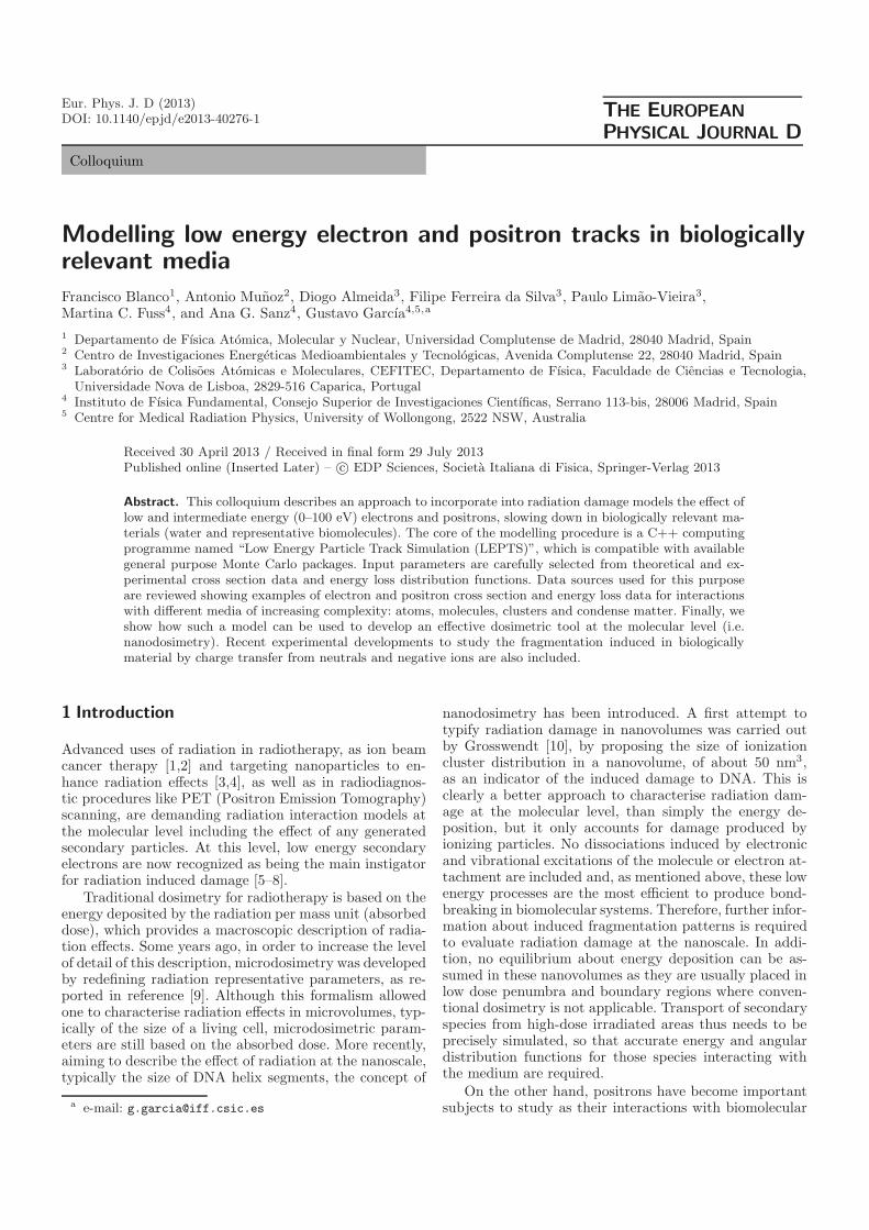
In order to model liquids and solids, they can beapproximated as homogeneous mixtures of atoms ormolecules, depending on which scattering target unit weconsider, with geometrical properties determined by theirtemperature and density. Taking Ar as an example, andassuming that the screening corrections are not very de-pendent on the direction of the projectile we can applythe SCAR procedure in a similar way as we accomplishedfor molecules and clusters, in order to calculate the effec-tive cross section (σeff) of an Ar atom within the liquid.A representation of the screening situation for different
(a) (b) (c)
Fig. 1. Geometric representation of the Ar atomic cross sec-tions for (a) high, (b) intermediate and (c) low incident energyelectrons.
electron energies is shown in Figure 1. For high energyelectrons (Fig. 1a), above 100 eV, where the atomic elec-tron scattering cross sections do not overlap, an indepen-dent atom representation of the solid is appropriate. How-ever, for intermediate energies (Fig. 1b), between 20 and100 eV, overlap between the atomic cross sections occursand the effective cross section of the atom i (σeff
i is lessthan the atomic cross section (σi) by the σij screeningcoefficients provided by the j surrounding atoms. At lowenergies (Fig. 1c), below 20 eV, the effective cross sectionapproaches to the cell size σeff
i = σc Note that as theatomic cross section (σI) increases, σeff
i decreases from σI
to σc according to the lattice geometry. For any consid-ered geometry we can approximate the corrective factorss = [σeff
i ]σI by the following binomial expansion:
s = [1 + (σc/σ)p]1/p (10)
where the degree of approximation to the considered ge-ometry is given by the negative exponent p. For the sit-uation illustrated in Figure 1, the polygonal geometry(Fig. 1b) is reached within 0.5% for p = −21 while thesquared lattice geometry (Fig. 1c) is reproduced, within1.5%, with p = −8. In practice, other intermediate ge-ometries should be considered so an intermediate value ofp = −10 seems to be a good compromise for this approx-imate treatment.
Scattering cross sections of single atoms or moleculesin a liquid or solid environment are then modified, withrespect to those of the isolated condition, by this environ-ment in a selective way, strongly dependent on the energyof the incident electron or positron. This situation will beillustrated later in Section 3 with some concise examples.
Using this technique to modify electron scatter-ing cross sections by heavy atoms (e.g., gold, gadolin-ium) when they are forming solid nanoparticles, pro-vides a mechanism of introducing these radiation effectenhancers [3,4] into the present model.
2.2 Electron and positron scatteringcross section measurements
It is not possible to measure all the data required by ananoscale radiation damage model, such as that we arepresenting here. This is why the scattering procedure de-scribed in the previous section is considered the main datasource, dedicating the experiment to obtain reliable re-sults for selected processes and selected energies to eithervalidate theory or to provide information about processesout of the scope of the theoretical methods we use. Note

Page 6 of 18
that no cross section data as a function of the energytransfer in the collision are provided by our calculationprocedure, and therefore all the energy loss informationrequired by the model originates from the experiment.Other relevant experimental data are the total scatter-ing cross sections, as they can be considered as referencevalues, giving the sum of the integral cross sections forall the scattering processes as well as the mean free pathalong the particle tracks; the total and partial ionisationcross sections which, in combination with our calculatedintegral inelastic data, provide a reference value for thenon-ionising inelastic channels (electronic excitation, neu-tral dissociation); and positronium formation, in the caseof positrons, which provides more than the 90% of theannihilations in the medium. Remaining scattering infor-mation not entirely provided by our theoretical and ex-perimental techniques, such as vibrational excitation andelectron attachment cross sections are taken from the lit-erature (see Ref. [52] for example). Descriptions of ourexperimental techniques have been published in previouspublications, and therefore only a brief summary of themis required here. Additional details can be found in themain references we provide in the text that follows.
2.2.1 Total scattering cross sections
Total electron scattering cross sections (TCS), from 50 to5000 eV, are measured with a transmission beam appa-ratus. The attenuation of a linear electron beam is mea-sured as a function of the well-known target density withhigh angular (less than a 10−5 sr acceptance angle at thedetector) and energy (better than 10−4 of the ratio ofthe energy spread divided by energy) resolution. We havebeen using this technique for years and obtaining reliable,to within 5%, electron scattering TCS for a wide vari-ety of molecules (see Ref. [53] and references therein). Asalready mentioned, these TCS values are used as a refer-ence since they represent the sum of the ICS for all theprocesses and so should be consistent with the values usedfor all the available open channels at a given energy. Be-low 50 eV, we variably use a compromise value betweenour calculated TCS and the experimental data availablein the literature [52].
Concerning total positron scattering cross sections,even though technical complications arise from the needof moderating the energy of the positrons emitted by aradioactive source, and their current intensity limitations,a similar beam attenuation measurement method can befollowed [39,54]. Most of the experimental TCS data forpositrons we use in this modelling procedure have been ob-tained with a modified beam attenuation technique basedon a Surko trap prototype [55]. Basically positrons emit-ted by a ∼50 mCi Na-22 source are slowed down witha frozen Ne moderator and cooled in a gas mixture trapvia vibrational excitation of the molecules inside that gascell. In a pulsed mode operation, under an axial confiningmagnetic field of 0.2 T, bunches of positrons with energydistributions around 40–6 meV are accelerated throughthe scattering chamber containing the molecular target
in question. At the exit of the chamber the intensity ofthe transmitted positrons is recorded as a function of en-ergy by means of a retarding field analyser. Details ofthe experimental method and set-up used can be foundin reference [56].
A final validation of the electron and positron TCSdata we use for a given target, is provided by their ex-trapolation to higher energies. According to the first Bornapproximation, at energies high enough to validate thisapproach, the TCS values are not dependent on the chargesign, and therefore they should coincide for electrons andpositrons.
2.2.2 Ionisation cross sections
Electron impact ionisation cross sections are measured ina pulsed crossed beam experiment in combination witha time of flight (TOF) spectrometer to analyse the massand charge of the generated positive ions after the colli-sion. Details of the experimental set-up and methods toobtain absolute cross section values can be found in ref-erences [44,53]. In general, we measured directly the totalionisation cross section by using a pulsed ionisation cham-ber [44] and by combining those results with the massanalysis provided by the TOF spectrometer we determinethe ion fragmentation pattern as a function of the incidentelectron energies. Ionisation cross section data are essen-tial for modelling procedures. They are intimately linkedto biological radiation damage and ionisation is the mainmechanism to generate low energy electrons representing,for energies above 50 eV, about 80% of all the inelastic pro-cesses. In addition, ionic fragmentation probabilities willbe required for future developments in modelling indirectdamage by radicals (not implemented at the moment).
As far as positrons are concerned, ionisation processesare even more relevant for biomedical applications thanthey are for electrons. Apart from direct ionisation pro-cesses, similar to those occurring for electrons, positro-nium formation and direct annihilation processes finallylead to ionisation of the target [57]. Note that these twolatter mechanisms are the basis of PET scanning applica-tions. Direct annihilation is several orders of magnitudeless probable than the previous channels, so we can con-sider the total ionisation cross section for positron impactas the sum of the direct ionisation and the positronium for-mation cross sections. As shown in reference [57], a mag-netic confined positron beam apparatus similar to thatdescribed in the previous section can be used to measureselected inelastic channels: electronic excitation, positron-ium formation and direct ionisation. By tuning the retard-ing field analyser (RFA) to the energy loss range involvedfor the inelastic process of interest, the ratio between thecorresponding inelastic cross section and the observed to-tal cross section can be determined [58]. Until now, theexperimental system described in the previous sectionhas been devoted to the measurement of total scatteringand positronium formation cross sections. For this reason,the direct ionisation cross section data we used for mod-elling [38] are taken from the literature and especially from

Page 7 of 18
the extensive work carried out in this field by the positrongroup at University College London [59].
2.2.3 Electronic excitation and other inelastic channels
At intermediate energies (5–50 eV), electronic excitationsprovide a considerable contribution to the total inelas-tic cross sections. From the experimental point of view,it is not easy to obtain absolute numbers for the totalelectronic excitation cross sections. By using a conven-tional crossed beam electron scattering apparatus [60,61],with an appropriate angular and energy resolution, dif-ferential electronic excitation cross sections for selectedexcited states can be measured as we did in previousstudies [62,63].
Other inelastic channels, such as the vibrational androtational excitation and the electron attachment pro-cesses, become dominant at lower energies, below theelectronic excitation threshold (typically below 3 eV).Available experimental data for these processes stronglydepends upon the target and the energy range we areconsidering. In general, except for water molecules [64],they are scarce and limited to specific energies. A recentexample of a critical analysis of available data, in orderto get a complete cross section data set, being consistentwith our experimental and theoretical data, is shown inreference [65].
For positrons, the situation with respect to these re-maining inelastic channels is even worse and we usuallyhave to take modified electron scattering data in order tocomplete our modelling procedure. Vibrational and rota-tional excitations are assumed to be the same as thosecorresponding to the electron case. Electronic excitationsof the target are restricted to those states which do notinvolve spin flip, and attachment is not included.
2.3 Energy loss distribution functions
Event by event Monte Carlo modelling procedures, suchas that presented here, rely on the scattering distribu-tion probabilities derived from cross sectional data. Thosedetermine the type of process taking place in any singlescattering event, and the angular distribution of the scat-tered and ejected particles (incident projectile and sec-ondary species). Another critical parameter to define theparticle track structure is the energy transferred in thoseevents. The first approach to include this parameter wouldbe considering not only differential cross sections with re-spect to the scattering angle, but also differential crosssections with respect to the energy, i.e. the doubly dif-ferential cross section or even the triply differential crosssection if angular and energy correlation between scat-tered and ejected particles is also given. Recent efforts toobtain this information for electron scattering from waterand biomolecules, both theoretically and experimentallyhave been made [66–68]. However, these measurementsare laborious if one is to cover the wide angular and en-ergy ranges required and although the 3-body distorted
wave method of calculation showed reasonable qualitativeagreement with the experimental differential cross sec-tions [68] it is not always consistent with the observedtotal ionisation cross sections [44]. While not ruling outthe possibility of a future implementation of such a triplydifferential scattering model in our track simulation pro-cedure, we decided to follow a different approach which ismore convenient to our experimental and theoretical con-text. Basically, we use as input parameters to model theenergy transferred in a scattering event the energy lossdistribution functions derived from our experimental en-ergy loss spectra. The advantage of this method is basedon two pieces of important experimental evidence:
1. For high energy electrons or positrons (above 100 eV)the energy loss spectra are almost independent of theincident energy and scattering angle. For increasingenergies, electrons and positrons are preferably scat-tered in the forward direction and the energy loss dis-tribution between 0 and 100 eV energy loss is almostconstant [52]. Only above inner shell excitation ener-gies (285 eV for C atoms) do additional structures,about two orders of magnitude less intense, need to beincluded [65].
2. For low energies, say below 50 eV, the above conditiondoes not apply and different energy loss distributionfunctions should be considered for different scatteringangles.
Systematic studies with representative molecules con-nected with biological media (H2O, CH4, C2H4, THF,pyrimidine) have been carried out in three different ex-perimental apparatus in order to cover a broad energyrange from 10 to 5000 eV. The low energy electron scat-tering apparatus are standard crossed beam experimentslocated at Flinders University (Australia) and the Uni-versite de Liege (Belgium). Their energy resolution wastypically within 50 to 80 meV, depending on the require-ments of the measurement, and a rotatable hemispheri-cal electrostatic spectrometer covered typically the scat-tering angles between 10 and 120◦. For higher energies,from 50 to 50 000 eV, we used the spectrometric systemplaced at CSIC-Madrid, and analysed the energy of a lin-ear electron beam passing through a pressure controlledgas cell. The angle of analysis is defined by deflecting thescattered beam with an electrostatic quadrupole coveringthe angular range 0–10◦. Averaging measurements fromboth systems, for different energies and different scatter-ing angles, we concluded that within a 20% uncertaintywe can represent the electron scattering energy loss, formodelling purposes, with only two normalised distribu-tion functions. As an example, results for CH4 are shownin Figure 2.
In some particular cases, where details at the very endof the track are essential, additional energy loss distribu-tion functions, for a limited energy and angular range, canbe included as input data for the model with a subsequentincrease of the computational task.
Other important information derived from the energyloss spectra in combination with the calculated differ-ential elastic cross sections, are the angular distribution

Page 8 of 18
Fig. 2. Average electron energy loss distributions used forthe high and low incident energy ranges. In the inset, origi-nal spectra measured in CH4 for different energies (from 20 eVto the keV range) are compared. For 20 and 40 eV, the spectrashown are the average over all measured angles.
functions for inelastic processes. As can be seen in refer-ence [65], by comparing the differential cross section forinelastic processes as a function of the energy transferredin the collision, with the corresponding differential crosssection, we can obtain an empirical formula,
d2
σ(E)dΩΔE∝
(dσ(E)
dΩ
)1−ΔE/E
el
, (11)
which reproduces to a good approximation the experimen-tal energy loss spectra as a function of the scattering angle.
For positrons we assume the same energy distributionfunctions as for the electrons. Few experimental energyloss spectra can be found in the literature for positrons,and even less with measurements as a function of the scat-tered positron angles. However as positronium formationleads to annihilation which does not affect the energy lossdistributions, no important differences with the electroncase can be expected.
3 Input data examples
Data requirements and the main sources from where weacquire them, which we use to model single electron andpositron tracks in biologically relevant media, have beendiscussed in the previous section. Here we now providesome examples, on the particular cross sections and for-mats that we use for representative targets and partic-ularly for water. Results for other biomolecules can befound in the references cited in the previous section.
Integral electron scattering cross sections for collisionswith water molecules are shown in Figure 3. A completeanalysis to derive these data has been carried out in ref-erences [44,69]. Although integral cross section data areusually plotted in a logarithmic scale (see Refs. [44,69]),here are plotted in a linear scale in order to appreciatethe relative relevance of each scattering process along theenergy range considered in this study.
Fig. 3. Electron scattering integral cross sections for collisionswith water molecules that are used as input parameters formodelling single electron tracks in water vapour. Details ondata sources and the procedure followed to get a consistent setof data can be found in [69].
Total cross sections and ionisation cross sections aretaken from our previous measurements, but complementedwith other experimental data available in the literature.Elastic and rotational excitations are the calculated withthe previously detailed procedures and the analysis ofother available data in order to get a complete set of con-sistent data can be found in reference [69]. As discussedin [69], for energies below 5 eV, the high resolution totalcross section measurements from Jones and Field [70]1 hasbeen taken as reference values and therefore our calculatedrotational excitation cross sections have been modulatedin order to get consistence with those experimental values.
Angular distribution functions for elastic processes arederived from our differential elastic cross section calcu-lation. Typical results for water molecules are shown inFigure 4, for energies ranging from 1 to 10 000 eV.
For inelastic processes, similar angular distributionsare derived from equation (11). Figure 5, therefore, showsan example for a 100 eV incident energy electron and dif-ferent energy loss values ranging from 0 (elastic) to 70 eV.
An example of an energy loss distribution function forhigh incident energies (typically above 100 eV) in wa-ter is shown in Figure 6. As described earlier, at theseenergies only one averaged energy loss distribution func-tion is required. Below this energy, different energy lossdistribution functions for different energy and scatteringangles, according to the requirements of the modellingprocedure [69], are utilised.
Input data for positrons are obtained as described inthe previous section. Figure 7 shows a comparison be-tween the total scattering cross sections for electrons andpositrons in water, as calculated with the procedure de-scribed in Section 2.1. As expected, the positron andelectron total scattering cross section tends to be equal
1 And private communication.

Page 9 of 18
Fig. 4. Electron elastic scattering differential cross sections forcollisions with water molecules, which are used to derive angu-lar distribution functions for modelling single electron tracksin water vapour.
Fig. 5. Electron inelastic scattering differential cross sectionsfor collisions with water molecules, which are used to deriveangular distributions as a function of the energy loss, accordingto equation (11).
when the energy gets large enough. In the case of watermolecules, both data merge for energies above ∼1 keV.
To illustrate how condensation effects can modify dif-ferential and integral electron scattering cross sections,elastic electron scattering differential cross sections for Aratoms and for the dimer, trimer and tetramer Ar clusters,are plotted in Figure 8 for 1, 10 and 100 eV incident en-ergies. As can be seen, the angular distributions of thescattered electrons are modified depending on the size ofthe cluster. To quantify the tendency of those condensa-tion effects as a function of the number of atoms in thecluster, Figure 9 represents the percentage deviation ofthe differential electron scattering cross section of the Arn
clusters (n = 2, 3, 4) with respect to that correspondingto a single Ar atom at 1 eV. As shown in this figure, some
Fig. 6. A high energy (above 100 eV) electron energy loss dis-tribution function in water, as derived from the experimentalspectra. (a) Total energy loss range, (b) detail for 0–100 eVenergy loss.
Fig. 7. Electron and positron total scattering cross sectionsfor collisions with water molecules, as calculated with theIAM-SCAR procedure.
forward and backward angles are favoured by the presenceof neighbouring atoms while some intermediate angles re-main almost unaffected. These variations on the angulardistribution of the scattering cross sections are a conse-quence of the coherent sum of the scattering amplitudescorresponding to the single atoms.
Similarly, the percentage deviation of the total electronscattering cross section of Arn(n = 2, 3, 4) clusters withrespect to that corresponding to isolated atoms, are plot-ted in Figure 10. As shown in this figure, the total crosssections always decrease when the number of atoms in thecluster increases but this effect is much more prominentfor energies around 20 eV.
Applying a similar procedure to water molecules, wecan transform scattering data corresponding to isolatedmolecules into those equivalent to molecules in a liquid

Page 10 of 18
Fig. 8. Elastic electron differential scattering cross sectionsfrom Argon atoms (Ar1) and Argon clusters (Ar2, Ar3, Ar4),in atomic units (a2
0/sr) for selected energies.
Fig. 9. Percentage deviation of the differential elastic electronscattering cross sections of Arn (n = 2, 3, 4) clusters, with re-spect to the corresponding isolated atom, for 1 eV incidentenergy.
state. The cross sections are modified by the correctivefactors calculated with the aforementioned IAM-SCARprocedure (see Sect. 2.1.4). Corresponding data for the in-tegral, elastic and inelastic, electron scattering cross sec-tions in liquid water are shown in Table 1. For energiesbelow 100 eV, the cross sections tend to be larger thanthe intermolecular surfaces and the condensation effectsstart to be appreciable. Calculated corrective factors aremultiplied by the corresponding molecular scattering crosssection, to obtain the effective cross section of the moleculein the liquid.
This representation of the electron and positron in-teraction with water molecules in the liquid phase is asimple approach based exclusively in the geometry of theproblem. It would be interesting to compare its predic-tions with other approximations available in the litera-ture. Most of those previous studies are based on the
Fig. 10. Percentage deviation of the total electron scatteringcross section for collisions with Arn(n = 2, 3, 4) clusters, withrespect to the corresponding to single atoms, as a function ofthe incident energy.
dielectric-response function, see Emfietzoglou et al. [71]for details, which relies on the calculation of a Bethe sur-face for liquid water [72]. Recently, Wiklund et al. [73] usedthis approach to derive energy loss properties and inelastic(excitation plus ionization) cross sections of electrons inliquid water. By combining these results with their calcu-lated elastic scattering cross section and electron attach-ment cross section data, for the gas phase, available in theliterature, they propose a cross section data set from 10to 10 000 eV to be used for modeling purposes. Present in-tegral elastic, inelastic and total scattering cross sectionsare plotted in Figure 11 together with the correspondingvalues of Wiklund et al. [73] for comparison. As this fig-ure shows, total scattering cross section data are in goodagreement, within 15%, for energies above 200 eV. Thisresult seems reasonable as for energies above this limitboth approximation consider that water molecules in theliquid phase behave, from the electron scattering point ofview, as if they were in the gas phase. However, looking atthe inelastic and elastic components, our integral inelasticcross sections are about 25% higher than those of Wiklundet al. [73] while our integral elastic values are about 20%than theirs. The discrepancy on the elastic could be justi-fied by the simple independent atom model they use whichdoes not consider relevant improvements we introducedin our potential [22,31] disregarding polarization and ab-sorption effects. We have shown for rare gases that theabsorption potential is always required even if only theelastic scattering is pursued. Otherwise, the calculated in-tegral elastic cross sections are overestimated. Concerningthe inelastic part, both set of data tend to converge forincreasing energies. This is consistent with the fact thatthe dielectric function method used in [73] is based onthe first Born approximation, and therefore tends to bemore accurate as the incident energy increases. When en-ergy decreases integral inelastic cross sections from [73]tend to be lower than ours, partially due to the dipole

Page 11 of 18
Table 1. Theoretical integral elastic, inelastic and total scattering (TCS) cross sections (10−20 m2 units) for water molecules inthe gas and liquid phases, respectively, as calculated with the IAM-SCAR procedure. Corrective factors as defined in Section 2.1.4are also given.
Energy (eV)Gas phase
Corrective factors (s)Liquid phase
Elastic Inelastic TCS Elastic Inelastic TCS1 30.0 98.0 128 0.0757 2.27 7.42 9.69
1.5 27.5 70.0 97.4 0.0994 2.74 6.96 9.692 25.3 54.9 80.1 0.121 3.06 6.64 9.693 21.3 38.9 60.2 0.161 3.42 6.26 9.694 18.0 30.5 48.5 0.200 3.59 6.10 9.695 15.5 25.1 40.6 0.239 3.71 5.98 9.697 13.5 18.7 32.2 0.301 4.08 5.64 9.6910 11.9 13.7 25.6 0.379 4.49 5.19 9.6915 10.0 10.1 20.1 0.483 4.82 4.86 9.6920 8.42 8.99 17.4 0.556 4.69 5.00 9.6830 6.22 8.37 14.6 0.664 4.13 5.56 9.6740 5.10 7.62 12.7 0.757 3.86 5.77 9.6350 4.37 6.94 11.3 0.840 3.67 5.83 9.5070 3.50 5.96 9.44 0.945 3.31 5.63 8.91100 2.74 4.96 7.70 0.990 2.71 4.91 7.63150 2.08 3.95 6.02 0.999 2.08 3.94 6.01200 1.71 3.33 5.04 1.0 1.71 3.33 5.04300 1.30 2.56 3.86 1.0 1.30 2.56 3.86400 1.07 2.10 3.19 1.0 1.072 2.11 3.19500 0.918 1.81 2.72 1.0 0.918 1.81 2.72700 0.722 1.41 2.13 1.0 0.722 1.41 2.131000 0.554 1.07 1.63 1.0 0.554 1.07 1.632000 0.319 0.613 0.932 1.0 0.319 0.613 0.9323000 0.228 0.431 0.661 1.0 0.228 0.431 0.6615000 0.146 0.275 0.420 1.0 0.145 0.275 0.420
10 000 0.0795 0.148 0.227 1.0 0.0795 0.148 0.227
induced excitation cross sections which are not consideredin the calculation of Wiklund et al. [73]. Unfortunately, forlower energies, below 100 eV, where the liquid propertiesare expected to be dominant, no relevant conclusion canbe derived from this comparison. The dielectric functionmethod used in [73] for the inelastic part does not work atsuch low energies, where the Born approximation cannotbe applied and, as mentioned in Section 2.1, the indepen-dent atom model they used to calculate the elastic parttend to overestimate the cross section for energies belowof about 100 eV.
Another important aspect we need to consider, in or-der to apply our simulation procedure to the liquid phase,is the energy loss distribution function to be used. Asmentioned above, for independent molecules in the gasphase, we use the energy loss distribution functions de-rived from our experiments. Those experiments do notrun for liquids and as far as we know related data inthe literature are almost inexistent, especially for the lowenergies where we are particularly interested here. How-ever we can still use our energy loss distribution functionsfor isolated molecules after some modification, if required,via an approach based on the collisional stopping power(−dE/dx)col, or energy loss per unit path length (x), ofelectrons in H2O according to the expression [44]:
−1ρ
(dE
dx
)col
=Na
MEσinel, (12)
Fig. 11. Integral electron scattering cross sections in liquidwater. Present work: -, total scattering cross section; -.-, inte-gral inelastic cross section; —, integral elastic cross section.Reference [73]: -, total scattering cross section; -.-, integralinelastic cross section; —, integral elastic cross section.
where ρ is the density of the target, σinel is the integral in-elastic cross section, Na is the Avogadro constant, M themolar mass and E is the mean excitation energy derivedfrom the experimental energy loss spectra. The stoppingpower of high energy particles in liquids can be calculated

Page 12 of 18
with reasonable accuracy (depends on the energy of theparticle) by using the properties of the dielectric function,as developed in reference [71], within the framework ofthe first Born approximation. In the case of water, cal-culated electron stopping powers for vapour and liquidwater are available in the NIST databases [74] for ener-gies above 1 keV. At these energies, the stopping powersof electrons in liquid water differ from those correspondingto water vapour by less than 2%. This difference is withinthe estimated error limits for our energy loss distributionfunction for water molecules and, given the condensationcoefficient at these energies equals to 1, we can concludethat the energy loss distribution functions derived for wa-ter vapour (see Fig. 6) are also valid for liquid water. Inother cases the energy loss distribution functions can beslightly shifted in energy, but maintaining their shape inorder to obtain the appropriate average energy loss.
4 Monte Carlo simulations
Following the procedures described in Sections 2 and 3,we can obtain a complete set of input data for the sim-ulation programme. For this purpose we designed a newprogramme with the following requirements:
1. compatible with general purpose Monte Carlo codescommonly in use for radiation dosimetry, suchas GEANT4 (Geometry And Tracking4) [75] andPenelope (PENetration and Energy Loss of Positronsand Electrons) [76]. Those programmes have beenproven for high energy electrons and photons. Thiscompatibility allowed us to restrict our code develop-ment to the low energy domain, below 10 keV;
2. incorporating a flexible tool to define targetcomposition and geometries;
3. including a powerful visual tool to be implemented inmedical applications, allowing interactive output op-tions depending on the characteristics of the problemin question.
4.1 Low energy particle track simulation(LEPTS) programme
Under these initial assumptions, we decided to baseour first design on the GEANT4 tool kit developedat CERN [75]. This covers all the high energy pro-cesses and is flexible enough to allow us to incorporateall the new physics related to low energy electron andpositron interactions. These new processes form the coreof our low energy particle track simulation (LEPTS) code.Additionally, we incorporated other related tools suchas GAMOS (GEANT4-Based Architecture for Medicine-Oriented Simulations) [77]. This combination provides avaluable set of tools related to the simulation of particletransport through matter. We use them to simulate ma-terials, particle tracking, hit processes, build geometries,etc. A wide range of physical processes are available, so wecan concentrate our effort on the interaction of low energy
LEPTS Code
Interac�on cross sec�on data
Energy loss distribu�on
Angular distribu�on
Source geometry and emission spectra
General MC Programme
Laboratory verifica�on
Medical Imaging
GAMOS Architecture
Fig. 12. Flow diagram of the modelling procedure: inputs,output and feedback.
(0–10 keV) electrons and positrons. All this new physicshas been introduced by writing a new C++ code whichincludes all the required processes: elastic, ionisation, elec-tronic excitation, vibro-rotational excitation, electron at-tachment, positronium formation, etc. using our collisionaldatabases as input parameters (see Sect. 3). These newmodules were integrated into the GAMOS’ plug-in archi-tecture and a compact set of plug-ins has been developedto account for the physics calculations, geometry, data col-lecting, statistics, etc. More information about the initialdevelopment of the programme as well as its technical de-tails can be found in references [78,79].
Lately, we have developed a graphic tool (LEPTS-Visor) targeting the task of visualization and analysis ofthe collisional data. This tool uses the available OPENGLlibrary to perform fast rendering of trajectories generatedby the simulation code. Users can visualize the whole ir-radiated area or selecting regions of interest, even at thenano scale, and the option menu offers all the informa-tion related to the region of interest: energy deposited(absorbed dose), total number of interactions, number ofspecific processes (ionisations, dissociations, elastic events,etc.) acting as a bridge between molecular alterations andpossible radiation effects.
The first biomedical applications of this model weredevoted to brachytherapy, with photons emitted by I-125seeds and electrons coming from a Ru-106 eye applicatorplaque [80,81]. As shown in references [80,81], the dosime-try of the highly irradiated areas is fairly coincident usingLEPTS and other dose planners but, in the lowly irradi-ated areas, where traditional dose planners do not assignappreciable energy deposition, low energy secondary elec-trons are still producing damage in terms of molecular dis-sociation. The main present challenge for the validation ofour model is to correlate observed side-effects in medicalradiation treatments with these molecular alterations in-duced in sensitive areas close to the irradiated tumours.A flow diagram of inputs and outputs of the LEPTS mod-elling procedure is shown in Figure 12. Note that verifi-cation experiments refer to preclinical trials currently inprogress to systematize nanoscale predicted damage withobserved biological dysfunctions.
Although the sampling procedure of our LEPTS codehas been described in previous publications (see references

Page 13 of 18
Fig. 13. Flow diagram of a single electron track simulationwith the low energy particle track simulation (LEPTS) code.
above) a brief summary of the entire process is given inthe next paragraph.
In order to optimize the computing time consumption,the LEPTS procedure is only applied to secondary elec-trons with kinetic energies lower than 10 keV. In appli-cations where the primary radiation particles are photonsor high energy (>10 keV) electrons, the first step of thesimulation is run with GEANT-4, but the coordinate, en-ergy and direction of every low energy electron generatedis registered in an independent file. Then, a second sim-ulation step is carried out by using the LEPTS code forthose low energy (<10 keV) electrons in the selected regionof interest. The track simulation procedure of such a lowenergy electron is illustrated in Figure 13. Once this elec-tron is generated with an energy (E < 10 keV) the MonteCarlo procedure produces a collision event by samplingthe total cross section at that energy. Then, by samplingthe elastic and inelastic integral cross sections, it decideswhether the collision is elastic or inelastic. If it is elastic,after the collision process, the kinetic energy of the elec-tron is almost the same as the incident (the kinetic energytransferred to the molecular target is negligible, comparedto the incident energy, but it is accounted for). However,the direction of the scattered electron changes accordingto the angular distribution function (normalized proba-bility as a function of the scattering angle) derived fromthe differential elastic cross section. If it is inelastic, theprogramme samples the single process integral inelasticcross sections (ionisation, excitation, attachment, etc.) todecide the type of interaction that is taking place and theenergy loss distribution function (normalised probabilitydistribution as a function of the energy loss) to evaluatethe energy transferred to the molecule. For any inelasticevent, the type of interaction and the energy transferredto the medium are registered. Additionally, if it is an ioni-sation process, a new secondary electron is generated. Theenergy of this secondary electron is determined by the dif-ference between the energy transferred and the ionisationpotential of the molecule while its direction is simply given
Fig. 14. An example of single electron tracks simulation inliquid water. (a) 1000 electrons with 10 keV incident ener-gies slowing down by successive collisions (coloured balls).(b) Nanovolume detail close to the end of a selected track. Thecolour of the balls indicates the type of interaction: •, elasticscattering; •, rotational excitation; •, vibrational excitation; •,electronic excitation; •, neutral dissociation; •, ionisation; •,electron attachment.
by the application of the momentum conservation to theincident and the two emerging electrons.
4.2 Single electron and positron tracksimulation examples
In order to show the characteristics and possible applica-tions of this modelling procedure, we have chosen someexamples of electron and positron tracks in liquid waterwith initial energies of 10 keV. Under these conditions, sin-gle tracks for 1000 electrons until their final thermalisationare shown in Figure 14.
As can be seen in Figure 14, maximum penetration of10 keV electrons in liquid water is less than 5 μm. All theinformation about energy deposition and type of inter-action taking place during the thermalisation procedureis provided by the model. Both the type of interactionand the energy deposition is sorted by the simulation pro-gramme according to the probability distribution func-tion derived from the cross sections and the energy lossdistributions. At the very end of each track, when no in-elastic processes are energetically available, electrons areconsidered thermalized after a certain number of succes-sive elastic collisions (solvated electrons are not consideredhere). This information, corresponding to 10 single elec-tron tracks, is shown in Table 2 for the whole irradiatedvolume and for a selected nanovolume close to the end ofan electron track.
Looking at the information shown in Table 2 for thewhole irradiated area, the total energy deposition corre-sponds to the initial electron energy, namely 10 000 eV. Asfor the information relative to the selected nano-volume,we can see that the energy deposition is about 372 eV,which will lead to a meaningless absorbed dose in it. How-ever, several tens of dissociative processes in the volumeare inducing damage in terms of bond breaking and struc-tural modification of the molecules constituting the media.This is the way we define the nano-dosimetry, characteris-ing the induced damage in terms of molecular dissociations

Page 14 of 18
Table 2. Information about energy deposition and the type ofinteractions derived from the simulation of 10 single electrontracks of 10 keV incident energy in liquid water, both for thetotal irradiated volume and a selected nano-volume.
Total Selectedirradiated nano-
area volume
Volume 116 µm3 3677 nm3
Energy deposition 100 000 eV 371.9 eVNumber of events:– Elastic scattering 1 348 762 4364– Rotational excitation 276 818 984– Vibrational excitation 39 928 131– Electronic excitation 390 1– Neutral dissociation 1821 8– Ionisation 3498 13– Electron attachment 282 1– Auger electrons 29 0
instead of absorbed dose. In this context, the simulationprocedure described above can be considered as a use-ful nano-dosimetric tool for those applications which mayrequire this level of detail.
Similar simulations can be carried out for positrons.The main differences compared to the corresponding elec-tron tracks can be found at the end of the tracks, wherelow energy positrons are able to form positronium andthen annihilate. In fact, the end of most of the positrontracks is positronium formation (direct annihilation, oc-curring only at very low energy, is a very unlikely processcompared to positronium formation). Figure 15 shows theend of a positron track in water. As in the previous fig-ure for electrons, the colour of the plotted balls representsthe type of interaction (see Fig. 15). The particular caseshown in this figure contains 1778 elastic collisions, 569 ro-tational excitations, 64 vibrational excitations, 2 neutraldissociations, 3 ionisations and 1 positronium formationwhich finally leads to the positron annihilation producingtwo 0.511 MeV photons (not shown in the picture) whichescape from the medium in opposite directions.
It is difficult to estimate the accuracy of these simu-lated electron and positron tracks. The numerical uncer-tainties linked to the Monte Carlo procedures, when thenumber of processes used is big enough to minimize sta-tistical fluctuations, are completely negligible with respectto the uncertainties affecting to the input parameters, i.e.cross sections and energy loss functions. Considering inte-grated values (elastic, inelastic and total scattering crosssections) assigned uncertainties are within 5−15% whilefor differential cross sections, below 30 eV these valuescan be increased up to 50%. In our model, differential in-elastic cross sections are not related to each single processbut to the energy transferred to the medium (Eq. (11)).This is a simple empirical approach but reproduces the ob-served energy loss spectra for different angles within 20%.Concerning positron tracks, no big differences can be ex-pected with respect to the electron case except for thoseparameters for which no positron data are available andthe corresponding electron data are used, i.e. vibrational
Fig. 15. Detail of the situation at the end of a single positrontrack in liquid water. The colour of the balls indicates the typeof interaction: •, elastic scattering; •, rotational excitation; •,vibrational excitation; •, neutral dissociation; •, ionisation; •,positronium formation.
excitation and energy loss spectra. For energies above10 eV, both inelastic scattering and energy loss are domi-nated by positronium formation, electronic excitation andionisation. Therefore, this additional uncertainty due tothe lack of positron data would be only considered for lowenergies, below 10 eV.
As mentioned above, this modelling procedure hasbeen used for some medical applications [81], where therange of penetration and energy deposition of electronsin water as a function of depth are derived. This modelcan also be used to derive transport properties of elec-trons and positron, as well as positronium formation andthermalisation rates [20].
5 New capacities to implement to the model
Our modelling procedure describes, with a high level ofdetail, all the interaction processes related to the incidentparticles and the generated secondary electrons. However,the effects of other secondary species, such as charged orneutral radicals, are not considered. Positive and negativeions as well as neutral fragments can also induce impor-tant modifications to the structure and electron transferproperties of biological materials [82–84]. There are manypossibilities of interaction, causing damage [85] or activat-ing repair mechanisms [86], but we will initially focus onelectron transfer processes. The effect of these processesstrongly depends on the DNA component in question [82]and the subsequent reactions, leading to stabilization ofthe radical or producing irreversible effects, are affectedby numerous factors (geometry, temperature, energy bal-ance) which are not well understood at this moment. Ourfirst goal will be identifying anion fragmentation inducedin DNA constituents and other biomolecules, by electrontransfer from other radicals including both negative ionsand neutrals.

Page 15 of 18
Fig. 16. Mass spectra of anions produced in 4 keV H−,O− and OH− collisions with gas-phase water. The data hasbeen normalized to each other at a mass/charge ratio of17 Thomson (Th).
5.1 Fragmentation induced by negative ion chargetransfer processes
The goal of these experiments is to characterise the in-duced fragmentation patterns, as a function of the incidentenergy of the negative radical, as well as to identify therole of the neutral atom as a stabilizing third body afterthe electron transfer. The experimental setups are basi-cally crossed beam experiments where anion projectilesinteract with a molecular beam and the induced fragmen-tation is analysed by either a quadrupole mass spectrom-eter or a time of flight spectrometer, depending on theexperimental requirements.
The first experiments were carried out for relativelyhigh anion energy (1–4 keV). The anion beam was pro-duced in a PS-120 Negative Ion Caesium Sputter Sourceand the charge-mass ratio of the produced cationic andanionic fragments were analysed with an orthogonalquadrupole mass spectrometer. Details of these measure-ments and results for some representative molecules (ni-tromethane, water, ethanol, and methanol) can be foundin reference [87]. As an example, the anionic induced frag-mentation by 4 keV H−, O− and OH−collisions, withwater molecules, is shown in Figure 16.
As shown in this figure, fragments of 1, 16 and 17 Thare identified and we assigned them to H−, O− and OH−,respectively. Similar to free electron attachment, H− for-mation is the dominant fragment for all the projectiles,although its yield is comparable to the other fragments,which is not in agreement with the ionic yields in freeelectron attachment, where H− is one order of magnitudehigher than O− and two orders of magnitude higher thanOH− [65,88]. The yield of the most relevant fragment fromthe point of view of producing indirect damage, OH−,increases notably with the mass of the projectile [87].
Similar studies for lower incident anion energies arecurrently in progress in our laboratory in Madrid. Theexperimental setup used in this case is illustrated in Fig-ure 17. Here the ion source is a hollow cathode discharge
Fig. 17. Crossed beam experiment to study induced fragmen-tation of biomolecules by charge transfer from anionic radicals.Primary anion beam (a) is generated by a hollow cathode dis-charge over a supersonic beam provided by a pulsed valve. Theintensity and composition of the primary beam is monitoredby a time of flight spectrometer (TOF-1). This beam crossesan effusive molecular beam (b) containing the target of inter-est (THF, pyrimidine, DNA and RNA bases). Charged radi-cals produced as a consequence of the interaction are extractedthrough two opposite time of flight spectrometers, one for neg-ative ions (TOF-2) and the other for positive ions (TOF-3).
over a pulsed molecular beam generated by a piezoelec-tric supersonic valve. Negative ion radicals are extractedfrom the cathode and accelerated onto the collision region,which is perpendicularly crossed by a molecular beam con-taining the target of interest. This molecular target is pro-vided by an effusive beam generated by a temperaturecontrolled oven. Anions induced by charge transfer areanalysed in mass by a 0.92 m length TOF spectrometer.In the opposite direction, a shorter drift tube (0.52 m)analyses the mass of positive fragments produced as aconsequence of the atomic collision process.
These experiments are in progress, but the incorpora-tion into the model of fragmentation induced damage bycharge transfer from charged radicals is not still available.Preliminary measurements led to promising results, andafter a systematic study of different targets (THF, pyrim-idine, DNA and RNA bases) and related fragmentationspatterns the main indirect damage mechanisms should beable to incorporated along the track of the primary andsecondary particles.
5.2 Fragmentation induced by charge transferprocesses from neutral atoms
Not only can negative ions transfer electrons to surround-ing molecules but so to can neutral species, provided thatthe local molecular electronegativity makes the processenergetically accessible. Although our final objective willbe neutral radicals resulting from the irradiation, in or-der to understand the electron transfer mechanisms andthe physical parameters controlling the relative yield of

Page 16 of 18
Fig. 18. Negative ion time-of-flight mass spectra for 70 eV(laboratory frame) potassium collisions with gas phasethymine. See legends on figure for further details.
the different dissociation pathways, we started the ex-periments by measuring the fragmentation induced frompotassium atoms. This neutral atom is an excellent pro-totype for an electron donor projectile and can reveal im-portant information about the bonding properties of thebiomolecular systems of interest, as well as possible in-tramolecular electron transfer processes coupled with theelectron transfer collision.
The experimental arrangement to study these collisionprocesses is again a crossed beam configuration with aTOF mass spectrometer, but now using an energy con-trolled neutral potassium beam source. Experimental de-tails can be found in references [89,90]. Just to illustratethe output from the experiment, that is used to obtainsystematic patterns of induced fragmentation and relativeyields, TOF mass spectra of negative fragments generatedby electron transfer from potassium atoms to thymine anduracil molecules are shown in Figure 18.
In addition, dissociative electron attachment (DEA)processes leading to site-selective molecular fragmenta-tion and the possibility of using the electron energy asa parameter to control chemical reactions have been re-ported [91]. We have recently shown a similar site selec-tivity in collisions of neutral potassium atoms with thepyrimidine bases of DNA [92]. In this case, the projectileis converted into a positive ion after the collision and themolecular target becomes a temporary negative ion allow-ing access to parent molecular states which are not ac-cessible via free electron attachment experiments. Theseatom-molecule collision experiments, which presented ascharge transfer deposited on gas-phase thymine and uracilby an electron harpooning mechanism [90], induce the lossof hydrogen which exclusively takes place from the ni-trogen positions. The bond selectivity can also be madesite selective by proper adjustment of the collision en-ergy. These findings point to a new achievement in con-trolling chemical reactions that may have particular rel-evance for the investigation of early molecular processesin the nascent stages of DNA damage by secondary elec-trons, especially those related to strand breaks. However,
we are still quite far from getting a representative database to be included as input information for the simulationprogramme. Systematic charge transfer experiments fromdifferent neutral species, mainly residual radicals, collid-ing with electronegative DNA and RNA blocks are stillrequired.
6 Conclusions
To study the radiation effect in biologically relevant ma-terials, at the nanoscale level, it is indispensable to takeinto account the discrete nature of the radiation interac-tion processes. For these media, this requirement shouldnaturally extend to the length scale of other functionalunits, such as macromolecules and especially DNA. Fur-thermore, the analysis of quantities based solely on energydeposition to the medium cannot give a complete pictureof the induced radiation effects, particularly at low ener-gies. Due to the diverse nature of the possible interactions(and their different potential for inducing molecular al-terations independent on the energy they deposit), it isnecessary to consider the occurrences of different collisiontypes separately.
In this sense, we have presented a model to describeradiation interactions at the molecular level when theeffect of low energy electrons or positrons is demandedby the application of interest. This model is compatiblewith general purpose Monte Carlo simulation tools suchas GEANT4 and PENELOPE, so covering a broad en-ergy range from the high energy of the primary radiation,typically in the order of the MeVs, down the final ther-malisation of secondary particles in the order of the meVs.
The essential features of this simulation procedure arethe input probability distribution functions, which arepreviously derived from our experimental and theoreticaldata, complemented with a comprehensive review of avail-able information in the literature. We have summarisedthe main experimental techniques and calculation proce-dures we use to obtain these input data, through collabo-rations between the different institutions involved in thisstudy. Our IAM-SCAR calculation procedure, includingdipole rotations, has proven to be an excellent complementfor the differential and integral scattering cross sectionmeasurements carried out both in beam-gas transmissionand crossed beam experiments. More than ∼80% of the in-put information required by the model is provided withinthe framework of this collaboration. Remaining informa-tion, less than 20% of the whole required data, is takenfrom the literature. As an example, the consistency of theinput data bases has been demonstrated both for electronsand positron interacting with water. Water is an excellentrepresentative target, as it is the most abundant compo-nent of biological media and possesses common propertieswith other biomolecules such as a strong permanent dipolemoment.
We have presented, for the first time, a procedure toapply the IAM-SCAR method to calculate corrective fac-tors for the electron and positron scattering cross sectionfrom water molecules in the liquid phase. Although some

Page 17 of 18
experimental validation is still required, this is a power-ful tool to translate our single track simulation proce-dure from the gas phase to the condensed phase. It re-quires some complementary information about the energyloss distribution functions in condensed material but wehave proposed a method based on the high energy elec-tron (positron) stopping power which allows the trans-formation of those functions derived from the gas phaseexperiments.
The capability of the present model to describe radia-tion effects, in terms of molecular alteration (bond break-ing and dissociation) in nanovolumes (nanodosimetry),has been shown and discussed by simulating electron andpositron tracks slowing down in liquid water from incidentenergies of keVs until their final thermalisation.
Finally, state of the art of experiments to study in-duced fragmentation by electron transfer processes fromneutral atoms and negative ions have been illustrated. Theresults of these experiments will ultimately constitute anew input data base to incorporate into the model, forthe effect produced by neutral and anionic radicals capa-ble of inducing damage to DNA components via electrontransfer.
This work was partially supported by the Spanish Ministeriode Economıa y Competitividad (Projects FIS2009-10245and FIS2012-31230). Additional support from PortugueseFoundation for Science and Technology (FCT-MEC)through post-graduate SFRH/BD/61645/2009 and post-doctoral SFRH/BPD/68979/2010 grants as well as PEst-OE/FIS/UI0068/2011 and PTDC/FIS-ATO/1832/2012 isalso noted. This work also forms part of the EU/ESF COSTAction MP1002 “Nanoscale Insights into Ion Beam CancerTherapy (Nano-IBCT)”. Authors especially acknowledgethe members of the Australian Research Council Centreof Excellence for Antimatter-Matter Studies (CAMS) forproviding most of the experimental positron interaction crosssections used for the present modelling procedure, and, inparticular, Prof S.J. Buckman, Prof M.J. Brunger, Dr J.P.Sullivan, and Prof R.P. McEachran for their constructivediscussions while preparing this colloquium.
References
1. A.V. Solov’yov, E. Surdutovich, E. Scifoni, I. Mishustin,W. Greiner, Phys. Rev. E 79, 011909 (2009)
2. M. Kanazawa, A. Kitagawa, S. Kouda, T. Nishio, M.Torikoshi, K. Noda, T. Murakami, M. Suda, T. Tomitani,T. Kanai, Y. Futami, M. Shinbo, E. Urakabe, Y. Iseki,Nucl. Phys. A 701, 244 (2002)
3. S.J. McMahon, W.B. Hyland, M.F. Muir, J.A. Coulter, S.Jain, K.T. Butterworth, G. Schettino, G.R. Dickson, A.R.Hounsell, J.M. O’Sullivan, K.M. Prise, D.G. Hirst, F.J.Currell, Nat. Sci. Rep. 1, 1 (2011)
4. M.S. Strano, Nat. Mater. 9, 467 (2010)5. B. Boudaiffa, P. Cloutier, D. Hunting, M.A. Huels, L.
Sanche, Science 287, 1658 (2000)6. B. Bodaiffa, P. Cloutier, D. Hunting, M.A. Huels, L.
Sanche, Radiat. Res. 157, 227 (2002)
7. M.A. Huels, B. Boudaıffa, P. Cloutier, D. Hunting, L.Sanche, J. Am. Chem. Soc. 125, 4467 (2003)
8. G. Hanel, B. Gstir, S. Denifl, P. Scheier, M. Probst, B.Farizon, M. Farizon, E. Illenberger, T.D. Mark, Phys. Rev.Lett. 90, 188104 (2003)
9. ICRU Report 36, Microdosimetry (International Commis-sion on Radiation Units and Measurements, Bethesda,MD, USA, 1983)
10. B. Grosswendt, Radiat. Prot. Dosimetry 110, 789 (2004)11. G. Garcıa, F. Manero, Phys. Rev. A 53, 250 (1996)12. G. Garcıa, F. Manero, Phys. Rev. A 57, 1068 (1998)13. F. Manero, F. Blanco, G. Garcıa, Phys. Rev. A 66, 032713
(2002)14. M. Inokuti, M.R.C. McDowell, J. Phys. B 7, 2382 (1974)15. M. Inokuti, Rev. Mod. Phys. 43, 297 (1971)16. A. Dora, L. Bryjko, T. van Mourik, J. Tennyson, J. Phys.
B 45, 175203 (2012)17. Z. Masın, J. Gorfinkiel, J. Chem. Phys. 137, 204312 (2012)18. A.G. Sanz, M.C. Fuss, F. Blanco, F. Sebastianelli, F.A.
Gianturco, G. Garcıa, J. Chem. Phys. 137, 124103 (2012)19. M.A. Lima, L.M. Brescansin, A.J. da Silva, C. Winstead,
V. McKoy, Phys. Rev. A 41, 327 (1990)20. Radiation Damage in Biomolecular Systems, edited by
G. Garcıa Gomez-Tejedor, M.C. Fuss (Springer, London,2012)
21. N.F. Mott, H.S.W. Massey, The Theory of AtomicCollisions, 3rd edn. (Clarendon Press, Oxford, 1971)
22. F. Blanco, G. Garcıa, Phys. Lett. A 317, 458 (2003)23. R.D. Cowan, The Theory of Atomic Structure and Spectra
(University of California Press, London, 1981)24. M.E. Riley, D.G. Truhlar, J. Chem. Phys. 63, 2182 (1975)25. X.Z. Zhang, J.F. Sun, Y.F. Liu, J. Phys. B 25, 1893 (1992)26. G.G. Raju, IEEE Trans. Dielectr. Electr. Insul. 16, 1199
(2009)27. G. Staszewska, D.W. Schwenke, D. Thirumalai, D.G.
Truhlar, Phys. Rev. A 28, 2740 (1983)28. F. Blanco, G. Garcıa, Phys. Lett. A 255, 147 (1999)29. F. Blanco, G. Garcıa, Phys. Lett. A 295, 178 (2002)30. F. Blanco, G. Garcıa, Phys. Rev. A 67, 022701 (2003)31. F. Blanco, G. Garcıa, Phys. Lett. A 330, 230 (2004)32. O. Zatsarinny, K. Bartschat, G. Garcıa, F. Blanco, L.R.
Hargreaves, D.B. Jones, R. Murrie, J.R. Brunton, M.J.Brunger, M. Hoshino, S.J. Buckman, Phys. Rev. A 83,042702 (2011)
33. D.D. Reid, J.M. Wadehra, Phys. Rev. A 50, 4859 (1994)34. D.D. Reid, J.M. Wadehra, J. Phys. B 29, L127 (1996)35. D.D. Reid, J.M. Wadehra, J. Phys. B 30, 2318 (1997)36. X. Zhang, J. Sun, Y. Liu, J. Phys. B 25, 1893 (1992)37. R.P. McEachran, D.L. Morgan, A.G. Ryman, A.D.
Stauffer, J. Phys. B 10, 663 (1977)38. R.P. McEachran, J.P. Sullivan, S.J. Buckman, M.J.
Brunger, M.C. Fuss, A. Munoz, F. Blanco, R.D. White,Z. Lj Petroviæ, P. Limao-Vieira, G. Garcıa, J. Phys. B 45,045207 (2012)
39. M. Charlton, J.W. Humberston, Positron Physics(Cambridge University Press, Cambridge, 2001)
40. L. Chiari, A. Zecca, S. Giraradi, E. Trainotti, G. Garcıa,F. Blanco, R.P. McEachran, M.J. Brunger, J. Phys. B 45,215206 (2012)
41. J.B. Maljkoviæ, A.R. Milosavljeviæ, F. Blanco, D. Seviæ,G. Garcıa, B.P. Marinkoviæ, Phys. Rev. A 79, 052706(2009)
42. F. Blanco, G. Garcıa, J. Phys. B 42, 145203 (2009)

Page 18 of 18
43. A. Jain, J. Phys. B 21, 905 (1988)44. A. Munoz, J.C. Oller, F. Blanco, J.D. Gorfinkiel, P. Limao-
Vieira, G. Garcıa, Phys. Rev. A 76, 052707 (2007)45. A. Zecca, L. Chiari, G. Garcıa, F. Blanco, E. Trainotti,
M.J. Brunger, J. Phys. B 43, 215204 (2010)46. A.G. Sanz, M.C. Fuss, F. Blanco, F. Sebastianelli, F.A.
Gianturco, G. Garcıa, J. Chem. Phys. 137, 124103 (2012)47. A. Zecca, L. Chiari, G. Garcıa, F. Blanco, E. Trainotti,
M.J. Brunger, New J. Phys. 13, 063019 (2011)48. A.S. Dickinson, J. Phys. B 10, 967 (1977)49. A.G. Sanz, M.C. Fuss, F. Blanco, Z. Masın, J.D. Gorfinkiel,
F. Carelli, F. Sebastianelli, F.A. Gianturco, G. Garcıa,http://dx.doi.org/10.1016/j.apradiso.2013.01.031
50. A. Garcıa-Sanz, F. Carelli, F. Sebastianelli, F.A.Gianturco, G. Garcıa, New J. Phys. 15, 013018 (2013)
51. B. Ulrich, A. Vredenborg, A. Malakzadeh, L. Ph. H.Schmidt, T. Havermeier, M. Meckel, K. Cole, M.Smolarski, Z. Chang, T. Jahnke, R. Dorner, J. Phys.Chem. A 115, 6936 (2011)
52. M.C. Fuss, A. Munoz, J.C. Oller, F. Blanco, M.-J.Hubin-Franskin, D. Almeida, P. Limao-Vieira, G. Garcıa,Chem. Phys. Lett. 486, 110 (2010)
53. M.C. Fuss, A. Munoz, J.C. Oller, F. Blanco, D. Almeida, P.Limao-Vieira, T.P.D. Do, M.J. Brunger, G. Garcıa, Phys.Rev. A 80, 052709 (2009)
54. Atomic Physics with Positrons, edited by J.W.Humberston, E.A.G. Armour (Springer, London, 1988)
55. J.P. Sullivan, S.J. Gilbert, J.P. Marler, R.G. Greaves, S.J.Buckman, C.M. Surko, Phys. Rev. A 66, 042708 (2002)
56. J.P. Sullivan, A. Jones, P. Caradonna, C. Makochekanwa,S.J. Buckman, Rev. Sci. Instrum. 79, 113105 (2008)
57. J.P. Marler, C.M. Surko, Phys. Rev. A 72, 062713 (2005)58. A.C.L. Jones, C. Makochekanwa, P. Caradona, D.S.
Slaughter, J.R. Machacek, R.P. McEachran, J.P. Sullivan,S.J. Buckman, A.D. Stauffer, I. Bray, D. Fursa, Phys. Rev.A 83, 032701 (2011)
59. G. Laricchia, S. Armitage, D.E. Leslie, M. Szhuinska, P.Van Reeth, Rad. Phys. Chem. 68, 21 (2003)
60. V. Vizcaino, J. Roberts, J.P. Sullivan, M.J. Brunger, S.J.Buckman, C. Winstead, V. McKoy, New J. Phys. 10,053002 (2008)
61. H. Kato, K. Anzai, T. Ishihara, M. Hoshino, F. Blanco, G.Garcıa, P. Limao-Vieira, M.J. Brunger, S.J. Buckman, H.Tanaka, J. Phys. B 45, 095204 (2012)
62. T.P.T. Do, K.L. Nixon, M. Fuss, G. Garcıa, F. Blanco,M.J. Brunger, J. Chem. Phys. 136, 184313 (2012)
63. T.P.T. Do, M. Leung, M.C. Fuss, G. Garcıa, F. Blanco, K.Ratnavelu, M.J. Brunger, J. Chem. Phys. 134, 1443021(2011)
64. Y. Itikawa, N. Mason, J. Phys. Chem. Ref. Data 34, 1(2005)
65. M.C. Fuss, A.G. Sanz, A. Munoz, T.P.D. Do, K. Nixon,M.J. Brunger, M.-J. Hubin-Franskin, J.C. Oller, F. Blanco,G. Garcıa, Chem. Phys. Lett. 560, 22 (2013)
66. C.J. Colyer, S.M. Bellm, B. Lohmann, G.F. Hanne, O.Al-Hagan, D.H. Madison, C.G. Ning, J. Chem. Phys. 133,1240302 (2010)
67. C. Champion, Phys. Med. Biol. 55, 11 (2010)68. J.D. Builth-Williams, S.M. Bellm, D.B. Jones, Hari
Chaluvadi, D.H. Madison, C.G. Ning, B. Lohmann, M.J.Brunger, J. Chem. Phys. 136, 024304 (2012)
69. A. Munoz, F. Blanco, G. Garcia, P.A. Thorn, M.J.Brunger, J.P. Sullivan, S.J. Buckman, Int. J. MassSpectrom. 277, 175 (2008)
70. R. Eurık, J.P. Ziesel, N.C. Jones, T.A. Field, D. Field,Phys. Rev. Lett. 97, 123202 (2006)
71. D. Emfietzoglou, K. Karava, G. Papamichael, M.Moscovitch, Phys. Med. Biol. 48, 2355 (2003)
72. M. Dingfelder, M. Inokuti, Radiat. Environ. Biophys. 38,93 (1999)
73. K. Wiklund, J.M. Fernandez-Varea, B.K. Lind, Phys. Med.Biol. 56, 1985 (2011)
74. M.J. Berger, J. Coursey, M. Zucker, J. Chang, TechnicalReport NISTIR 4999 (National Institute of Standardsand Technology, 2009), http://www.nist.gov/pml/data/star/index.cfm
75. S. Agostinelli et al., Nucl. Instrum. Methods A 506, 250(2003)
76. J. Sempau, E. Acosta, J. Baro, J.M. Fernandez-Varea, F.Salvat, Nucl. Instrum. Meth. B 132, 377 (1997)
77. M. Canadas, P. Arce, P. Rato Mendes, Phys. Med. Biol.56, 273 (2011)
78. A. Roldan, J.M. Perez, F. Blanco, A. Williart, G. Garcıa,J. Appl. Phys. 95, 5865 (2004)
79. A. Munoz, J.M. Perez, G. Garcıa, F. Blanco, Nucl.Instrum. Meth. A 536, 176 (2005)
80. M.C. Fuss, A. Munoz, J.C. Oller, F. Blanco, P. Limao-Vieira, A. Williart, C. Huerga, M. Tellez, G. Garcıa, Eur.Phys. J. D 60, 203 (2010)
81. M.C. Fuss, A. Munoz, J.C. Oller, F. Blanco, A. Williart,P. Limao-Vieira, M.J.G. Borge, O. Tengblad, C. Huerga,M. Tellez, G. Garcıa, Appl. Rad. Isot. 69, 1198 (2011)
82. S. Steenken, Biol. Chem. 378, 1293 (1997)83. S.O. Kelley, J.K. Barton, Science 283, 375 (1999)84. M. Ratner, Nature 397, 480 (1999)85. M. Dizdaroglu, P. Jaruga, Free Rad. Res. 46, 382 (2012)86. S.D. Bruner, D.P.G. Norman, G.L. Verdine, Nature 403,
859 (2000)87. D. Almeida, R. Antunes, G. Martins, G. Garcia, R.W.
McCullough, S. Eden, P. Limao-Vieira, Int. J. MassSpectrom. 311, 7 (2012)
88. J. Fedor, P. Cicman, B. Coupier, S. Feil, M. Winkler, K.Gluch, J. Husarik, D. Jaksch, B. Farizon, N.J. Mason, P.Scheier, T.D. Mark, J. Phys. B 39, 3935 (2006)
89. D. Almeida, R. Antunes, G. Martins, S. Eden, F. Ferreirada Silva, Y. Nunes, G. Garcia, P. Limao-Vieira, Phys.Chem. Chem. Phys. 13, 15657 (2011)
90. F. Ferreira da Silva, D. Almeida, R. Antunes, G. Martins,Y. Nunes, S. Eden, G. Garcia, P. Limao-Vieira, Phys.Chem. Chem. Phys. 13, 21621 (2011)
91. R. Balog, E. Illenberger, Phys. Rev. Lett. 91, 213201(2003)
92. D. Almeida, F. Ferreira da Silva, G. Garcıa, P.Limao-Vieira, Phys. Rev. Lett. 110, 023201 (2013)