modelling and simulation of a solar photovoltaic air ... · department of mechanical and aerospace...
TRANSCRIPT

Department of Mechanical and Aerospace Engineering
Modelling and Simulation of a Solar Photovoltaic Air
Conditioning System for Cooling an Office Building
in Lagos, Nigeria
Author:
Oluwaseun Akintola
Supervisor:
Dr. Paul Tuohy
A thesis submitted in partial fulfilment for the requirement of the degree
Master of Science
Sustainable Engineering: Renewable Energy Systems and the
Environment
2014

Copyright Declaration
This thesis is the result of the author’s original research. It has been composed by
the author and has not been previously submitted for examination which has led to
the award of a degree.
The copyright of this thesis belongs to the author under the terms of the United
Kingdom Copyright Acts as qualified by University of Strathclyde Regulation 3.50.
Due acknowledgement must always be made of the use of any material contained in,
or derived from, this thesis.
Signed: Date: 6th September, 2014
3
Table of Contents Pages
Acknowledgements.......................................................................................................6
Abstract.........................................................................................................................7
CHAPTER 1: Introduction........................................................................................8
1.1: Nigeria`s Energy Crisis and the need for Off-grid Cooling Systems..............8
CHAPTER 2: Literature Review..............................................................................10
2.1: Solar PV Potentials for Nigeria..........................................................................10
2.2: Overview of Building Construction in Nigeria.................................................13
CHAPTER 3: Project Objectives and Research Methodology..............................16
CHAPTER 4: Modelling and Simulation.................................................................17
4.1: Step 1: Building the model to determine the cooling demand........................17
4.1.1: Model Geometry, Construction, and Attribution...............................................18
4.1.2: Model Operation Schedules...............................................................................20
4.1.3: Zone Controls.....................................................................................................23
4.1.4: Simulations.........................................................................................................24
4.2: Modelling for electrical load profile of the air-conditioning unit...................28
4.3: Modelling for Solar PV output power and size................................................29
4.4: Modelling for Battery Storage...........................................................................34
4.4.1: Battery Capacity.................................................................................................35
CHAPTER 5: Discussion...........................................................................................37
CHAPTER 6: Conclusion..........................................................................................39
REFERENCES...........................................................................................................40
APPENDIX.................................................................................................................43

4
List of figures Pages
Fig.1: Construction Phase of a Storey Building in Nigeria..........................................13
Fig.2: Base case model for a single occupant office in Nigeria...................................17
Fig.3: Typical view of a single occupant office in Nigeria..........................................17
Fig.4: Casual gains for the office.................................................................................20
Fig.5: Air flow Schedules.............................................................................................21
Fig.6: Weather Profiles.................................................................................................22
Fig.7: Cooling Demand for Early Rainy Season..........................................................24
Fig.8: Cooling Demand for Late Rainy Season...........................................................24
Fig.9: Cooling Demand for Early Dry Season.............................................................25
Fig.10: Cooling Demand for Mid Dry Season.............................................................26
Fig.11: Cooling Demand for Late Dry Season.............................................................26
Fig.12: Air-Conditioner Load Profile...........................................................................28
Fig.13: PV Generation Profile for Early Dry Season...................................................31
Fig.14: PV/Air-Conditioner Electrical Profile.............................................................32
Fig.15: PV/AC/Battery Generation Profile..................................................................34
Fig.16: Battery Profile..................................................................................................36
Fig.17: Solar PV powered Air-Conditioner (window unit)..........................................43
Fig.18: Solar PV powered Air-Conditioner (split unit)................................................43
5
List of tables Pages
Table.1: Model Construction Materials and Properties................................................18
Table.2: Best fit weeks.................................................................................................22
Table.3: Manufacturer Data for Air-Conditioning Unit...............................................23
Table.4: Zone Control Period Data..............................................................................23
Table.5: Average Monthly Solar Insolation on a horizontal surface in Lagos.............29
Table.6: Solar Manufacturer Data................................................................................30

6
Acknowledgements
This project is dedicated to the Almighty God and the Lord Jesus Christ for giving me
the enablement to start and finish the work.
I give highest regards to my parents, Mr & Mrs Akintola, for their financial and moral
support throughout the course of my masters program.

7
Abstract
The need for off-grid cooling systems is pivotal to meeting cooling demands for
developing countries located in tropical climates as a result of hot weather conditions
and inadequate power supply. This thesis proposes a solar PV powered air-
conditioning system as a suitable off-grid solution to meet the cooling demand for the
ground floor office of a commercial building in Lagos, Nigeria. The goal behind the
proposed off-grid cooling system is to reduce the load on the weak grid infrastructure
and offset all unit electricity costs associated with cooling load. The aim of the project
is to carry out modelling and simulation analysis for the ground floor office to
determine the required cooling load using ESP-r software. The solar PV and battery
requirements were analysed using Excel Spreadsheet. The results from the analysis
showed that for a peak cooling load of 9.37kW, an off-grid cooling system made up of
an air-conditioner having a maximum nominal capacity of 10.55kW, a solar PV array
of surface area 23m2 and a battery size of 24V 440Ah will be required to meet the
cooling demand for the ground floor office.

8
CHAPTER 1: Introduction
The focus of this section is to showcase the need for an off-grid solution to meet cooling demand
amongst other energy demands in tropical regions, due to harsh weather conditions and
inadequate power supply. This chapter discusses the crisis marring Nigeria`s energy network and
advocates the need for off-grid systems. The chapter also highlights a brief summary of the work
covered.
Chapter 2 gives a detailed literature review on the potentials for solar PV in Nigeria and an
overview of building and construction practices in Nigeria. Chapter 3 explains the objectives of
the project, problem the project intends to solve (i.e. the goal behind the project) and states the
steps that will be taken for the research methodology. Chapter 4 showcases the procedures of,
and results from the modelling and simulation analysis. Chapter 5 gives a detailed discussion
about the upshots of the results derived from the modelling analysis and opines on the
workability of the proposed system. Chapter 6 concludes the thesis and hints on suggestions that
will enhance the practical deployment of the proposed off-grid cooling system .
1.1 Nigeria`s energy crisis and the need for off-grid cooling systems
Nigeria is endowed with diverse natural resources which includes large reserves of fossil fuels
(Crude Oil, Natural Gas and Coal) and renewable energy sources (hydroelectricity, solar, wind
and biomass). However, sundry factors, most especially corruption, have impeded the maximum
utilization of these sources to meet overall energy demand of the nation. Since gaining
independence from Great Britain in 1960 till present, Nigeria`s economy has been marred by
inadequate power supply to foster economic growth and development. Currently, there are nine
energy generation plants in the country, three of which are hydro-powered, while the other six
are thermal power plants (Energy Commission of Nigeria, 2008)
The total installed capacity of the power plants is 6000MW although the energy generated has
been observed to be lower than installed capacity due to lack of maintenance, weak grid
infrastructure, interruption of fuel supply to thermal plants and a percentage of energy generated

9
being exported to a neighbouring country- Niger Republic (Uyigwe et al., 2009).The installed
generating electricity capacity in Nigeria consists of 1900MW of hydropower generation and
3396MW of thermal power generation (Kasimu, 2000). A prominent Nigerian newspaper named
PUNCH reported findings as of September 11 2009 that the country`s energy generation is about
2000MW. Research and Statistics has predicted Nigeria`s energy demand to be 35000MW in
2015 and will increase to 105,000MW in 2025 and 164,000MW in 2030 (Ibitoye and Adenikiju,
2006).
Oyedepo (2012) outlined and reviewed some of the most important energy conservation
opportunities and renewable energy options in Nigeria. He opined that there is an incremental
concern on the need to integrate renewable energy sources in Nigeria, considering the low rate of
socio-economic infrastructure achieved by over dependence on fossil fuels. The over dependence
on fossil fuels can be expressed as one of the upshots of corruption that has been the bane of the
Nigerian economy. National Technical Working Group on Energy Sector (2009) estimated the
supply capacities of renewable sources as thus; hydro-resources (small and large hydropower)
have an estimated capacity of 14,750MW, solar radiation is estimated at 3.5 – 7.0 KWh/m2/day,
wind energy has a potential of 150,000 terra joules per year (generated by an average wind speed
of 2.0 – 4 m/s) and biomass has an estimated capacity of 144 million tonnes per year.
According to the Energy Commission of Nigeria (2008), the Federal Government approved the
National Energy Policy (NEP) in 2003 to propose sustainable means of harnessing and utilising
all energy resources. Cardinal elements in the national policy emphasises on the development
and application of renewable energy technologies and they are as follows:
(i) To develop, promote and harness the renewable energy resources of the country and
incorporate all viable ones into the national energy mix.
(ii) To promote decentralised energy supply, especially in rural areas, based on RE
resources.
(iii) To promote efficient methods in the use of biomass energy resources.
(iv) To deemphasise and discourage the use of wood as fossil fuels.
(v) To keep abreast of international developments in renewable energy technologies and
applications.
10
The need for cooling systems in tropical regions in general and temperate regions during summer
as a result of hot weather conditions is pivotal to having thermal comfort. As a result, a large
percentage of electricity generated in countries with hot climatic conditions is channelled
towards meeting cooling demand in buildings. In Nigeria where the average weather temperature
is about 27°C, most of the energy demand that comes from commercial and industrial buildings
are attributed to cooling demand irrespective of the season- Dry or Rainy (Uyigwe et al., 2009).
Sivak (2009) examined the potential energy demand (average annual cooling and heating degree
days) for cooling in 50 largest metropolitan areas of the world and assessed the incremental
demand it would create on top of the energy demand. Lagos, the focus of this research, had an
average annual cooling degree day of 2653°C. His assessment indicated that air-conditioning is
rare in most developing countries that have hot climates primarily due to the cost of air-
conditioning appliances and the cost of energy. He opined that there is a likelihood of an increase
in air-conditioning as the personal income of residents in developing countries rise. The opinion
of Sivak (2009) can be viewed to be attainable if energy cost reduces and government initiatives
are set up and implemented to improve poverty alleviation.
The astronomical gap between the country`s energy demand and supply has sparked up a
plethora of energy policies by successive governments to help reduce the gap with a long term
pursuit of solving the problem. An optimum way inter alia to bridge this gap is firstly, to
disaggregate the total energy demand of the country into segments such as cooling demand,
heating demand, lighting demand, and other energy demands, and secondly, advocate for
standalone energy systems to meet a certain segment of the energy demand (e.g cooling
demand). This will offset total dependence on the current inadequate power supply from
conventional power generation to meet energy demand. In light of this, a solar photovoltaic
powered air-conditioning system is proposed to meet the cooling demand for the ground floor of
a single occupant office unit in a commercial building in Lagos, Nigeria.

11
CHAPTER 2: Literature Review
2.1 Solar PV Potentials for Nigeria
Nigeria`s tropical climate naturally makes it suitable for harnessing solar resources. Njoku(2013)
estimated Solar PV electricity generation potentials for all states in Nigeria by establishing a
linear equation between energy generation potential and solar insolation, and discovered that the
annual energy generation potential generally increases with latitude, hence in Nigeria`s case, the
extreme southern part of Nigeria (Niger Delta) had the lowest energy generation potential of
1,150kW.h/kWp for horizontal collectors and 1,200kW.h/ kWp for tilted collectors, while the
extreme north of the country (Sokoto State) had the highest energy potential of 1,705kW.h/kWp
for horizontal collectors and 1815 kW.h/kWp for tilted collectors. Lagos, the focus of this
research, had a potential of 1294 kW.h/kWp for horizontal collectors and 1339 kW.h/kWp for
tilted collectors. The results from his research evinced that, the use of solar PV in any part of the
country to meet energy demand can be seen to be technically feasible.
Several Solar PV installations have been carried out in different parts of the country with the aim
of meeting energy demand by harnessing solar resources within such areas. Ismail et al. (2012)
embarked on performance assessment of installed 4.5kW Solar PV systems in Oke-Agunla area
of Ondo State in Nigeria. The results from their assessment indicated that the Solar PV systems
were underutilised due to system faults and reduction in efficiency as a result of poor
maintenance, and technical defects being handled by fledgling project managers.
Agbo and Oparaku (2006) assessed the principles and technology of solar water heating, and
their future prospects in Nigeria. The results from their assessment indicated that the level at
which Solar Water Heating technology is being used in the Nigerian economy is extremely low
despite the fact that there are potentials for this technology and several researches have been
carried out about the profitability of the technology in the country. According to Oyedepo(2012),
heating equipments through cooking and water heaters consume about 60% of energy used in
households. Hence, the use of solar water heating technologies as mentioned in (Agbo and
Oparaku 2006) will help reduce the high level of heating demand in households.

12
Oparaku (2002) examined the problems in the electricity supply system in Nigeria, as well as the
status and potentials of Photovoltaics for village electrification and telecommunications. He
highlighted several Solar PV installations across rural villages where 80% of households had no
access to electricity grids and how the Solar PV systems met some of the energy demands.
Several solar PV installations for telecommunication masts which offset the cost of procurement
of diesel for diesel-powered generators used to power the masts, were also highlighted in his
research. Although, there were issues of intermittent breakdowns due to technical faults with
Solar PVs, he concluded that PV-powered village electrification systems have ameliorated the
standard of living in rural villages and PV-powered telecommunication systems have improved
the efficacy of the telecommunications network while offsetting the costs spent on diesel fuel.
Adaramola (2014) examined the feasibility of a solar PV-grid tied energy system for electricity
generation and also investigated the techno-economic performance of a combination of 80kW
solar PV and 100kW grid connection. He advocated for the use of the electricity grid to store
excess energy from the Solar PV in lieu of batteries, thus reducing the capital cost of the Solar
PV system and the unit cost of electricity. Although his research admitted the electricity
challenges faced in urban areas due to intermittent power supply as a result of inadequate
generation and distribution capacity, the results from his analysis indicated that a combination of
an 80kW Solar PV and 100kW power from the grid will generate an annual electricity of
331,536 kWh with solar PV contributing 40.4% of the electricity produced.
Oko et al. (2012) conducted a design and life cycle cost analysis and simulation study of PV
systems for the CAD/CAM laboratory at the University of Port-Harcourt in the Port-Harcourt
area of Nigeria. The results from their analysis unfortunately showed a unit electricity cost that is
higher than that for the municipal supply in the region. They however opined that the unit
electricity costs will drop to a reasonable value if the capital and installation costs of the PV
system components are either reduced or subsidised.
Several researches carried out in the literature for the deployment of Solar PV systems for
different scenarios in several parts of the country can be seen to have yielded positive results in
terms of meeting energy demand as required. However, the results from these analyses have
indicated sundry prevalent issues associated with long-term deployment of Solar PVs. Hence, it

13
is imperative that detailed research be carried out in solving the long-term problems associated
with deployment of Solar PV systems in Nigeria.
2.2 Overview of Building Construction in Nigeria
Primary materials used in construction of buildings in Nigeria include, but are not limited to,
corrugated roofing sheets, cement block for walls and foundations, wood for doors and
door/window frames, glass for window panes and reinforced concrete for slabs, beams and
columns (Ukoha and Beamish 1997).
Fig. 1: Construction phase of a storey building in Nigeria
Building standards and regulations in Nigeria came into inception in 2006 but prior to that, the
building construction industry was in a state of rollercoaster bombarded by diverse unqualified

14
individuals undertaking construction projects, thus leading to the use of untested and uncertified
materials and components (Mbamali and Okotie, 2012). The upshot of the mediocre
constructions carried out by fledgling contractors was inter alia the incessant collapse of
buildings and fire infernos and as a result of this, the National Council on Housing and Urban
Development established a National Building Code with the aim of offering solutions to the
innocuous trends in the building construction industry (Mbamali and Okotie, 2012). Despite the
efforts of the National Council on Housing and Urban Development as mentioned in (Mbamali
and Okotie, 2012), the enforcement and application of the National Building Code has
encountered several setbacks nationwide as there are still present occurrences of fire infernos and
collapse of buildings as a result of poor building standards.
Lawal and Ojo (2011) examined how building design characteristics, thermal performance of
buildings, thermal control in buildings affect prevention of overheating of buildings, reduction of
other heat gains, as well as thermal comfort and human performance by carrying out a field
survey of the thermal performance of four residential buildings in Ibadan, Nigeria. The results
from their research indicated that material selection, openings, orientation and provision of
vegetation around buildings contributed to the thermal comfort of occupants of residential
buildings in Ibadan, Nigeria.
Ukoha and Beamish (1997) examined the resident satisfaction with public housing in a public
housing district in Abuja, Nigeria and the relationship of satisfaction with specific housing
features to overall housing satisfaction. The results from their study showed that most of the
residents were not satisfied with individual housing features such as the plumbing, lighting,
floors, windows, doors, and finishing. In most cases, building designs drawn by architects reflect
the requirements of clients but ulterior motives of builders alter these requirements with a major
aim of maximising profit at the expense of customer satisfaction (Mbamali et al., 2004).
Research studies carried out on the status of energy efficiency in Nigerian buildings have been
seen to be disparaging. Iwaro and Mwasha (2010) investigated the implementation status of
building energy standards in 60 developing countries which included Nigeria, and its implication
for sustainable energy efficient designs in buildings. The results from their investigations
indicated that 42% of developing countries have no building energy standards which included
Nigeria.

15
Majid and Hussaini (2011) made attempts to verify the current level of energy efficiency design
practice in Nigeria as a result of the dominant issue of inefficient households. The results from
their analysis indicated that there was an obvious pattern of disorganised activities within the
building sector and also an existing gap in energy efficiency consideration and architectural
practice in Nigeria. There are a plethora of reasons for these gaps but are not limited to
corruption, lack of professional expertise in energy efficiency related issues, discord in execution
of roles for all parties (architects, engineers, quantity surveyor, and builder) involved in the
building construction (Mbamali et al., 2004).
Abimaje and Akingbohungbe (2013) discussed the capacity of energy efficiency in housing
Nigeria to serve as a panacea to climate change. They opined that a major issue with Nigerian
housing is the use of imported materials and construction techniques to satisfy the ego of modern
Nigerians. They stated that control measures are required to reduce the impact of solar radiation
on houses. In as much as Abimaje and Akingbohungbe (2013) opined the need for control
measures in buildings, their research did not take into consideration the feasibility of
implementing such control measures in buildings.
There is a prevalent absence of pertinent data and proper documentation of material properties
used in building construction in Nigeria and as a result, there are difficulties in carrying out
detailed modelling and simulation analyses for determining energy requirements in buildings
(Obanor and Egware, 2003). According to Obanor and Egware (2003), “the non-availability of
recent climatic design data have led to the usage by local building service engineers, of air-
conditioning system design data produced by foreign organisations like ASHRAE (American
Society of Heating, Refrigerating and Air-Conditioning Engineers) and CIBSE (Chartered
Institution of Building Service Engineers), which more often than not, results in the incorrect
estimation of space cooling loads and thus, ultimately affecting the design of air-conditioning
systems for buildings”. Based on the analysis carried out by Obanor and Egware (2003), it is
important to note that for Nigerian buildings to become energy efficient, it is pivotal that all
pertinent thermal and material properties used in construction from start to finish are researched
and documented so as to enable accurate modelling and design to meet energy efficiency
standards. This task can be effectuated through the establishment of policies and legislations by
the various building and construction regulatory organisations in Nigeria.

16
CHAPTER 3: Project Objectives and Research Methodology
Most office buildings in Lagos, Nigeria are storey buildings, flooded with air-conditioning
systems, and they are either powered by the electricity grid or diesel generators. This project
aims to model and carry out simulations for a solar photovoltaic air-conditioning system to meet
the cooling demand of an office located on the ground floor of an office building in Lagos,
Nigeria. This technology, if proven feasible, will provide two major energy efficient solutions;
To reduce the load on the weak grid infrastructure.
To offset all unit electricity costs from the municipal grid supply associated with cooling
demand.
The system components are:
(i) a Solar PV incorporated with
(ii) an air-conditioning unit and
(iii) an Auxilliary Storage (Batteries).
The research methodology for this project is as follows;
Step 1: Build a model of the office from scratch on ESP-r software, using relevant parameters
such as climate data, material and optical properties, zone construction and orientation, and zone
controls, to determine the cooling demand for the office.
Step 2: Get suitable COP values for the air-conditioning system from manufacturer`s data and
use the values to model for the required electrical power necessary to meet the cooling demand
for the office.
Step 3: Get solar insolation data for the site location and use the data to model for the size of the
Solar PV array that will generate a power output adequate to meet the electrical energy demand
of the air-conditioning system.
Step 4: Model for the size of the battery storage that will store excess power output from the
Solar PV and supply auxiliary power to meet electrical demands during peak periods.
17
CHAPTER 4: Modelling and Simulation
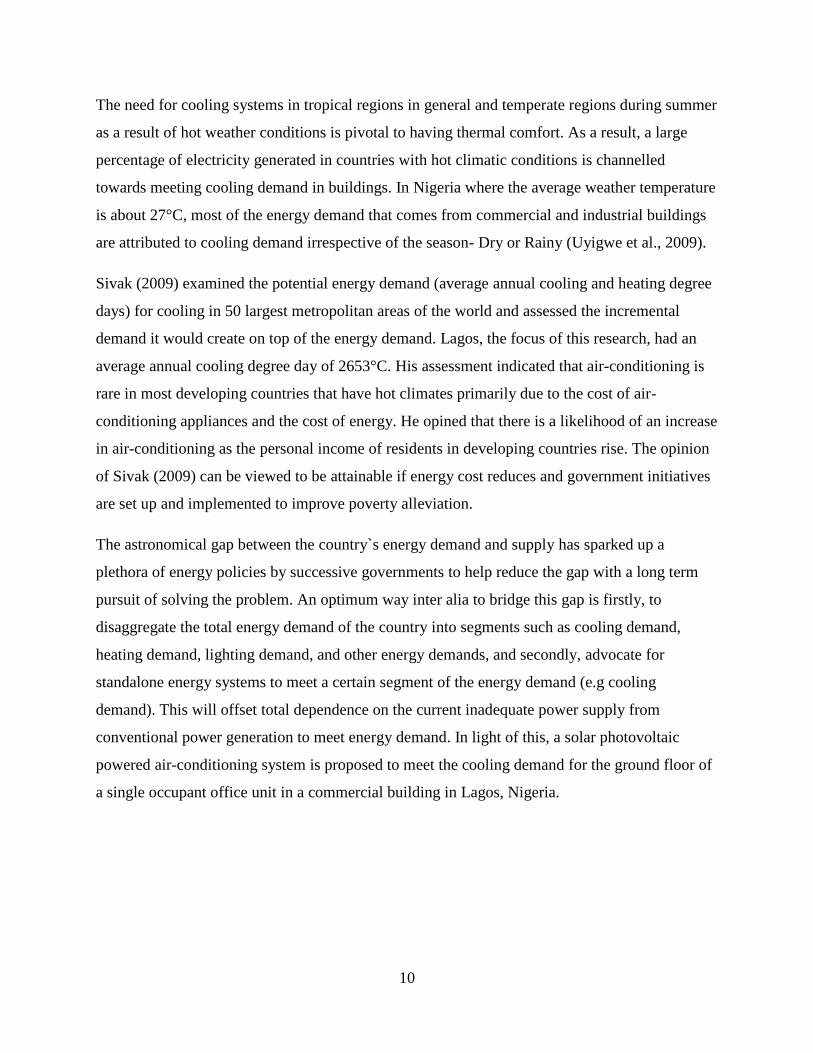
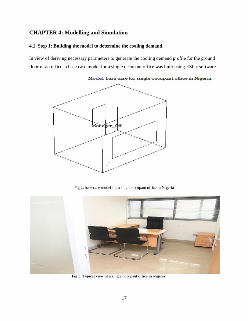
4.1 Step 1: Building the model to determine the cooling demand.
In view of deriving necessary parameters to generate the cooling demand profile for the ground
floor of an office, a base case model for a single occupant office was built using ESP-r software.
Fig 2: base case model for a single occupant office in Nigeria
Fig 3: Typical view of a single occupant office in Nigeria
18
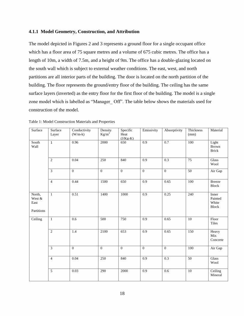
4.1.1 Model Geometry, Construction, and Attribution
The model depicted in Figures 2 and 3 represents a ground floor for a single occupant office
which has a floor area of 75 square metres and a volume of 675 cubic metres. The office has a
length of 10m, a width of 7.5m, and a height of 9m. The office has a double-glazing located on
the south wall which is subject to external weather conditions. The east, west, and north
partitions are all interior parts of the building. The door is located on the north partition of the
building. The floor represents the ground/entry floor of the building. The ceiling has the same
surface layers (inverted) as the entry floor for the first floor of the building. The model is a single
zone model which is labelled as “Manager_ Off”. The table below shows the materials used for
construction of the model.
Table 1: Model Construction Materials and Properties
Surface Surface
Layer
Conductivity
(W/m-k)
Density
Kg/m3
Specific
Heat
(J/Kg-K)
Emissivity Absorptivity Thickness
(mm)
Material
South
Wall 1 0.96 2000 650 0.9 0.7 100 Light
Brown
Brick
2 0.04 250 840 0.9 0.3 75 Glass
Wool
3 0 0 0 0 0 50 Air Gap
4 0.44 1500 650 0.9 0.65 100 Breeze
Block
North,
West &
East
Partitions
1 0.51 1400 1000 0.9 0.25 240 Inner
Painted
White
Block
Ceiling 1 0.6 500 750 0.9 0.65 10 Floor
Tiles
2 1.4 2100 653 0.9 0.65 150 Heavy
Mix
Concrete
3 0 0 0 0 0 100 Air Gap
4 0.04 250 840 0.9 0.3 50 Glass
Wool
5 0.03 290 2000 0.9 0.6 10 Ceiling
Mineral

19
Floor
1 1.28 1460 879 0.9 0.85 200 Earth
Sand
2 1.28 1460 879 0.9 0.85 200 Earth
Sand
3 1.28 1460 879 0.9 0.85 200 Earth
Sand
4 0.52 2050 184 0.9 0.85 150 Gravel
5 1.4 2100 653 0.9 0.65 150 Heavy
Mix
Concrete
6 0.6 500 750 0.9 0.65 10 Floor
Tiles
Glazing 1 0.76 2710 837 0.83 0.05 6 Glass
Plate
2 0 0 0 0 0 12 Air Gap
3 0.76 2710 837 0.83 0.05 6 Glass
Plate
Door 1 0.19 700 2390 0.9 0.65 25 Oak
Wood

20
4.1.2 Model Operational Schedules
Zone Casual Gains (Occupancy, Lights & Equipments) were defined for the model to estimate
the operational characteristics for each day type (weekdays, Saturday, Sunday, and holiday) and
air flow schedules were also defined.
Fig.4: Casual gains for the office
Fig.4 shows the casual gains profile for occupancy, lighting, and equipments in the office.
Saturday, Sunday and Holidays had no casual gains because offices are not opened during such
periods, thus the absence of any kind of activity. Only weekdays had casual gains due to work
activities. Each occupant is set to have a peak sensible gain of 100W and a peak latent gain of
half the value of the sensible gain (i.e. 50W). Hence, peak sensible gains of 200W for occupants,
at a given period indicate two people present in the office during such time. The same principle
can be likened to peak sensible gains of 300W for occupants- i.e. three people present. It can be
observed from Fig.4 that peak sensible and latent gains for occupants between (12:00 and 13:00
hours) dropped from (300W/150W) to (50W/25W). This indicates break-time during office
hours, hence no occupants in the office during that period.
Lightings and Equipments have zero latent casual gains, however sensible gains are estimated
based on respective power outputs from the appliance (lighting or equipment) for given set

21
periods. The office is presumed to use 20W of fluorescent lighting. Hence, a 40W lighting gain
between (08:00 and 09:00 hours) indicates two fluorescent tubes switched on. This could be due
to cleaners switching on the light to clean the office. A 100W lighting gain shows all five
fluorescent tubes switched on during office hours. The equipments in the office include a
desktop computer, and a printer/photocopier. These appliances have been estimated to have a
sensible gain of 100W and are operational between the hours of (09:00 and 18:00 hours). Hence,
it can be inferred from the casual gains profile for occupancy, lighting, and equipment that office
working hours are between 09:00 to 18:00.
Fig. 5 Air flow schedules
As shown in fig.5, air flow rates (infiltration) were scheduled at 10litres/second/person during
weekdays only, while minimum airflow rates throughout the week were scheduled at 0.5ac/h.
Due to unavailability of a weather file for Lagos, Nigeria, on ESP-r, a suitable weather file,
Accra Ghana, which has similar climatic conditions (Sub-Saharan Tropical Climate) with
Nigeria was imported from EnergyPlus Energy Simulation Software website and used for
simulation for different seasons of the year. The Sub-Saharan Tropical Climate has two seasons;
rainy season which spans between April and October, and dry season which spans between
October and March. Based on the weather file used for simulation, the model can be said to be
located at latitude 5.17°N and has a longitude difference of -0.17°.

22
Fig 6: Weather Profile
The weather profile, Fig.6, shows that the average peak ambient temperature for the five months
of the year (January to May) is about 33°C while the lowest set of ambient temperatures can be
said to be about 24°C within the same period. The months of June, July and August showed a
drop in average peak ambient temperature from about 33°C to about 30°C while the lowest set of
ambient temperatures can be said to be about 24°C. September to December indicated a return to
the same average peak ambient temperature that occurred within the first five months which is
about 33°C while the lowest set of ambient temperatures remained the same at 24°C. Although
there were few exceptions such as peak ambient temperature of over 46°C at the end of March
and very low set of ambient temperatures of 18°C in early July and 20°C at mid-November. A
detailed examination of the weather profile enabled the selection of the best fit weeks to carry
out weekly simulations for different seasons of the year. The table below shows the best fit
weeks:
Table 2: Best Fit Weeks
Seasons Best Fit Weeks Heating Degree Days
(°C)
Cooling Degree Days
(°C)
Early Rainy Season 10-Jul to 16-Jul 0 33.58
Late Rainy Season 22-Sep to 28-Sep 0 32.35
Early Dry Season 15-Nov to 21-Nov 0 45.0
Mid Dry Season 29-Jan to 04-Feb 0 47.05
Late Dry Season 15-Mar to 21-Mar 0 52.48

23
4.1.3 Zone Controls
Sensor and Actuator zone controls were setup for weekdays only, based on the following
manufacturer data.
Table 3: Manufacturer Data for Air-Conditioning Unit
Brand Name LG MULTIFDX
Model Number UHXM90BA0
Nominal Capacity (Cool)
(Min-Rated-Max)
1850W – 8880W – 10550W
Nominal Capacity (Heat)
(Min-Rated-Max)
2220W – 10100W – 12100W
Nominal Input (Cool)
(Min-Rated-Max)
720W – 2500W – 3160W
Nominal Input (Heat)
(Min-Rated-Max)
880W – 2300W – 3870W
EER/COP (cool) 3.52
COP (Heat) 4.39
Air Flow Rate 883 litre/sec
Cooling Operating Conditions Indoor Temperature: 27°C
Outdoor Temperature: 35°C
Heating Operating Conditions Indoor Temperature: 20°C
Outdoor Temperature: 7°C
Zone controls were set to sense a 50-50 mix of air and radiant temperatures.
The following values from Table.3 were used to define the sensor and actuator zone controls
Table 4: Zone Control Period Data
Cooling Set-Point Temperature 27°C
Heating Set-Point Temperature 20°C
Maximum/Minimum Cooling Capacity 10550W(Max) / 1850W(Min)
Maximum/Minimum Heating Capacity 12100W(Max) / 2220W (Min)
24
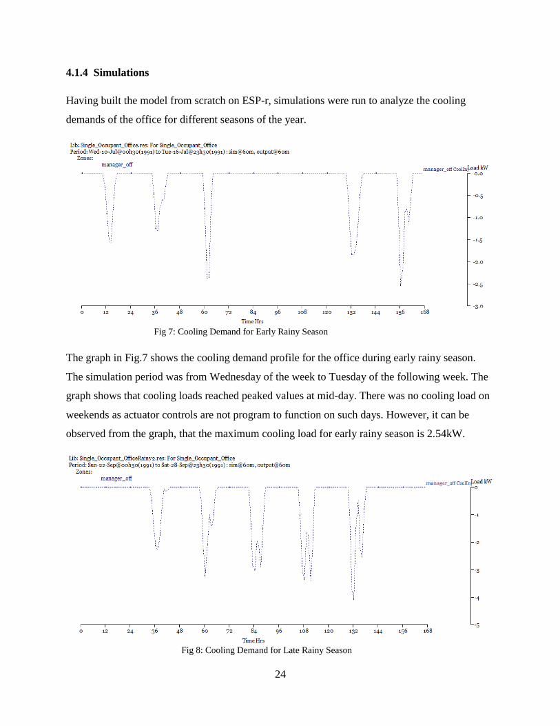
4.1.4 Simulations
Having built the model from scratch on ESP-r, simulations were run to analyze the cooling
demands of the office for different seasons of the year.
Fig 7: Cooling Demand for Early Rainy Season
The graph in Fig.7 shows the cooling demand profile for the office during early rainy season.
The simulation period was from Wednesday of the week to Tuesday of the following week. The
graph shows that cooling loads reached peaked values at mid-day. There was no cooling load on
weekends as actuator controls are not program to function on such days. However, it can be
observed from the graph, that the maximum cooling load for early rainy season is 2.54kW.
Fig 8: Cooling Demand for Late Rainy Season
25
The graph in Fig.8 shows the cooling demand profile for the office during late rainy season. The
simulation period was from Sunday to Saturday. The graph shows that cooling loads reached
peaked values at mid-day. There was no cooling load on weekends as actuator controls are not
program to function on such days. However, it can be observed from the graph, that the
maximum cooling load during the late rainy season is 4.06kW
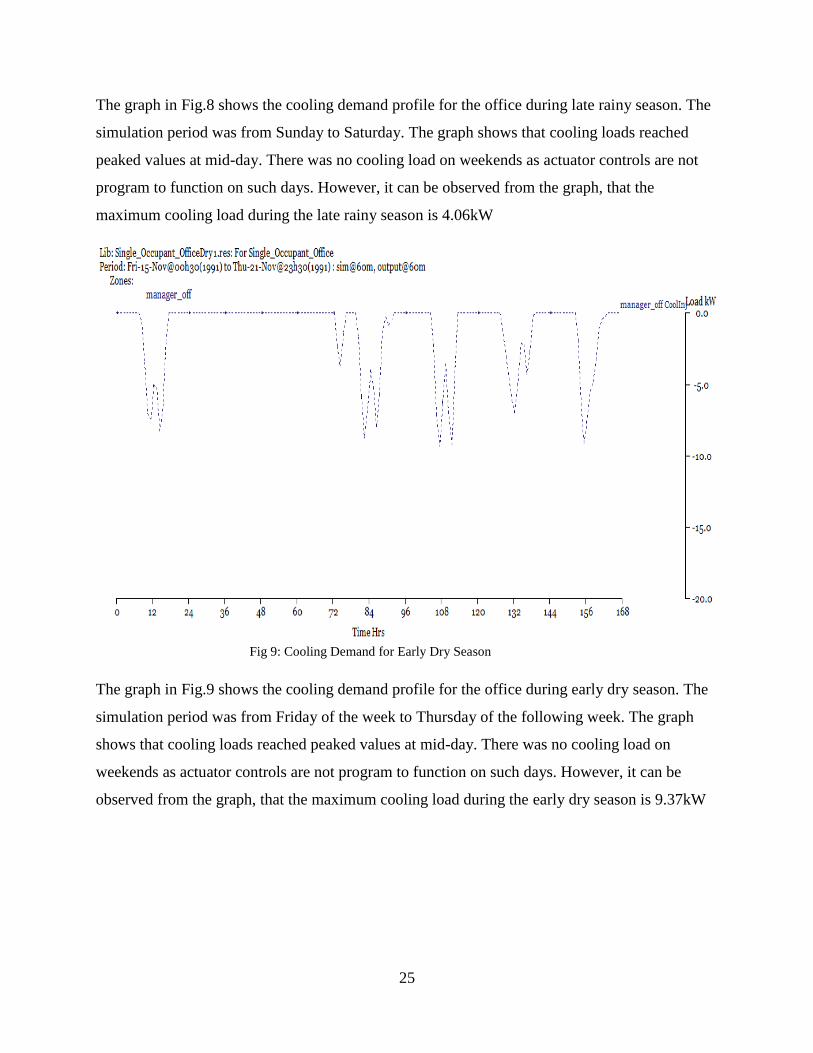
Fig 9: Cooling Demand for Early Dry Season
The graph in Fig.9 shows the cooling demand profile for the office during early dry season. The
simulation period was from Friday of the week to Thursday of the following week. The graph
shows that cooling loads reached peaked values at mid-day. There was no cooling load on
weekends as actuator controls are not program to function on such days. However, it can be
observed from the graph, that the maximum cooling load during the early dry season is 9.37kW

26
Fig 10: Cooling Demand for Mid Dry Season
The graph in Fig.10 shows the cooling demand profile for the office during mid dry season. The
simulation period was from Tuesday of the week to Monday of the following week. The graph
shows that cooling loads reached peaked values at mid-day. There was no cooling load on
weekends as actuator controls are not program to function on such days. However, it can be
observed from the graph, that the maximum cooling load during the mid-dry season is 9.01kW.
Fig 11: Cooling Demand for Late Dry Season

27
The graph in Fig.11 shows the cooling demand profile for the office during late dry season. The
simulation period was from Friday of the week to Thursday of the following week. The graph
shows that cooling loads reached peaked values at mid-day. There was no cooling load on
weekends as actuator controls are not program to function on such days. However, it can be
observed from the graph, that the maximum cooling load during the late dry season is 5.5kW
Having observed the cooling demand profiles for five different periods of the year, the maximum
peak cooling load of 9.37kW occurred during the early dry season. As a result, the cooling
demand profile for the early dry season (November) is regarded as the most optimum profile to
be used for deriving the electrical load of the air-conditioning system and the power output from
the Solar PV.
28
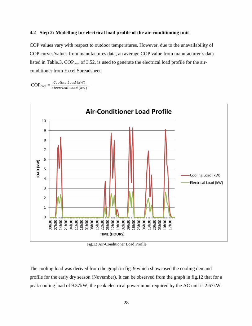
4.2 Step 2: Modelling for electrical load profile of the air-conditioning unit
COP values vary with respect to outdoor temperatures. However, due to the unavailability of
COP curves/values from manufactures data, an average COP value from manufacturer`s data
listed in Table.3, COPcool of 3.52, is used to generate the electrical load profile for the air-
conditioner from Excel Spreadsheet.
COPcool =
.
Fig.12 Air-Conditioner Load Profile
The cooling load was derived from the graph in fig. 9 which showcased the cooling demand
profile for the early dry season (November). It can be observed from the graph in fig.12 that for a
peak cooling load of 9.37kW, the peak electrical power input required by the AC unit is 2.67kW.
0
1
2
3
4
5
6
7
8
9
10
00
h3
0
07
h3
0
14
h3
0
21
h3
0
04
h3
0
11
h3
0
18
h3
0
01
h3
0
08
h3
0
15
h3
0
22
h3
0
05
h3
0
12
h3
0
19
h3
0
02
h3
0
09
h3
0
16
h3
0
23
h3
0
06
h3
0
13
h3
0
20
h3
0
03
h3
0
10
h3
0
17
h3
0
LOA
D (
kW)
TIME (HOURS)
Air-Conditioner Load Profile
Cooling Load (kW)
Electrical Load (kW)

29
4.3 Step 3: Modelling for Solar PV output power and size
Lagos is located at latitude 6.4531°N and 3.3958°E. The monthly averaged solar insolation
values for horizontal surfaces for 44,016 regions, generated on a nested grid that has a resolution
of one degree latitude globally and longitudinal resolution ranging from, one degree in the
tropics and subtropics, to 120° at the poles, can be culled from NASA Surface meteorology and
Solar Energy (NASA-SSE) website. In light of this, the monthly averaged insolation values for
horizontal surfaces (a horizontal solar PV array in this case) in Lagos, Nigeria, was extracted.
Optimum tilt angles for Lagos, Nigeria lies between 11.5° and 17.5°(Njoku, 2003). In most
cases, the worst case scenarios for both power absorbed by, and power output from, a PV array is
when it lies at horizontal i.e. at 0°. Hence, this work aims to model for the worst case scenario of
power generated by the PV to meet the electrical demand of the air-conditioning unit. The table
below shows the averaged monthly solar insolation on a horizontal surface in Lagos, Nigeria for
the month of November (Early Dry Season).
Table.5: Averaged monthly solar insolation on a horizontal surface in Lagos, Nigeria.
Latitude 6.453, Longitude
3.396
Time (hours)
November (Early Dry Season)
(Solar Insolation on PV array)
Power Absorbed (kW/m2)
Power Output from PV
array (kW)
Ƞ = 15.63%
@ 00 n/a 0
@ 03 n/a 0
@ 06 0.05 0.1813
@ 07 0.197 0.7144
@ 08 0.343 1.2438
@ 09 0.49 1.7768
@ 10 0.557 2.0187
@ 11 0.623 2.259
@ 12 0.69 2.502
@ 13 0.58 2. 1032
@ 14 0.47 1.7043
@ 15 0.36 1.3054

30
Time (hours) Solar Insolation on PV array Power Output from PV
@ 16 0.243 0.8822
@ 17 0.127 0.4591
@ 18 0.01 0.0363
@ 19 0 0
@ 20 0 0
@ 21 n/a 0
Table 6: Solar Manufacturer Data
Model Name Canadian Solar
Model Number CS6X-300P
Nominal Maximum Power (STC) 300W
Module Efficiency (STC) 15.63%
Module Dimension 1954 x 982 x 40mm
The peak electrical power required by the air-conditioning unit as shown in fig.12 is 2.67kW.
However, a solar PV array that will generate a peak power output of 2.5kW was investigated,
with the stipulation of storing excess energy generated on periods with low cooling demand and
reusing the stored energy to meet cooling demand at peak periods. From table.5, the peak
average solar insolation is 0.69kW/m2. This value, coupled with a peak PV module efficiency of
15.63% (STC) extracted from manufacturers data in table.6, was used to generate the size of the
solar PV array.
Power Output from PV (kW) = PV efficiency * Power Absorbed by PV (kW/m2) * Area (m
2)
2.5 (kW) = 0.1563 * 0.69 (kW/m2) * Area.
From this equation, the surface area for the PV array of 23.2m2was derived, and this area was
used to generate PV power outputs (kW) for all given values of solar insolation (kW/m2) gotten
from (NASA-SSE) website as shown in Table. 4. From table.5, the module area is 1954 * 982 =
1,918,828mm2 = 1.92m
2. Hence, for a total surface area of 23.2m
2 for the PV array, the total
number of required PV modules will be
= 12 modules.

31
The values of PV power outputs (kW) and the periods of subsequent power generation (hours)
was used to generate a solar PV power output profile from Excel Spreadsheet.
Fig.13: PV generation profile for early dry season (November)
The graph in fig.13 above shows the power output from the PV array having constant peaks of
2.5kW throughout the week. These idealistic values are as a result of the unavailability of daily
and weekly solar insolation values for Lagos, Nigeria. As a result, the average monthly solar
insolation for November was used to plot the graph.
0
0.5
1
1.5
2
2.5
3
00
h3
0
06
h3
0
12
h3
0
18
h3
0
00
h3
0
06
h3
0
12
h3
0
18
h3
0
00
h3
0
06
h3
0
12
h3
0
18
h3
0
00
h3
0
06
h3
0
12
h3
0
18
h3
0
00
h3
0
06
h3
0
12
h3
0
18
h3
0
00
h3
0
06
h3
0
12
h3
0
18
h3
0
00
h3
0
06
h3
0
12
h3
0
18
h3
0
Po
we
r O
utp
ut
(kW
)
Time (hours)
PV generation profile
PV

32
Fig.14: PV/Air-Conditioner electrical profile
The graph in fig.14 shows an integration of data derived for the electrical demand from the air-
conditioner in fig.12 and power output from the solar PV in fig.13. This integration was carried
out using Excel Spreadsheet to analyze the level of match between electrical demand from the
AC and power supply from the PV. The graph shows a week performance profile of the PV/AC
system starting from Friday of the week to Thursday of the following week. It can be observed
that Saturday and Sunday has no electrical demand as a result of non-working days at weekends
in the office, thus the air-conditioning unit is switched off.
Friday shows the PV generating excess power in the morning, thus exceeding electrical demand
by the AC, until hours after noon where electrical demand was higher than power supplied by the
PV. The PV generated power throughout the weekend despite that the air-conditioner was
switched off. There was a peak electrical demand of 1.05kW during the early hours of Monday
without any power supply from the PV. Later on, excess power was generated by the PV array
until noon when electrical demand was higher than power supplied by the PV. A similar pattern
can be observed on Tuesday with peak electrical demand higher than peak power output from
PV at noon. The PV power supply met most of the electrical demand for Wednesday and
0
0.5
1
1.5
2
2.5
3
00
h3
0
06
h3
0
12
h3
0
18
h3
0
00
h3
0
06
h3
0
12
h3
0
18
h3
0
00
h3
0
06
h3
0
12
h3
0
18
h3
0
00
h3
0
06
h3
0
12
h3
0
18
h3
0
00
h3
0
06
h3
0
12
h3
0
18
h3
0
00
h3
0
06
h3
0
12
h3
0
18
h3
0
00
h3
0
06
h3
0
12
h3
0
18
h3
0
Po
we
r O
utp
ut
(kW
)
Time (hours)
PV/AC electrical profile
PV
AC

33
Thursday except for later hours of Wednesday and noon on Thursday where electrical demand
exceeded power output from the PV.
The inability of the solar PV to supply adequate power to the air-conditioner at every instant of
time during working hours evinces the need to model for an auxiliary supply that will store the
excess power output from the PV during periods of low electrical demand, and re-supply the air-
conditioning unit system with the deficient power required to meet peak electrical demand.
34
4.4 Step 4: Modelling for Battery Storage
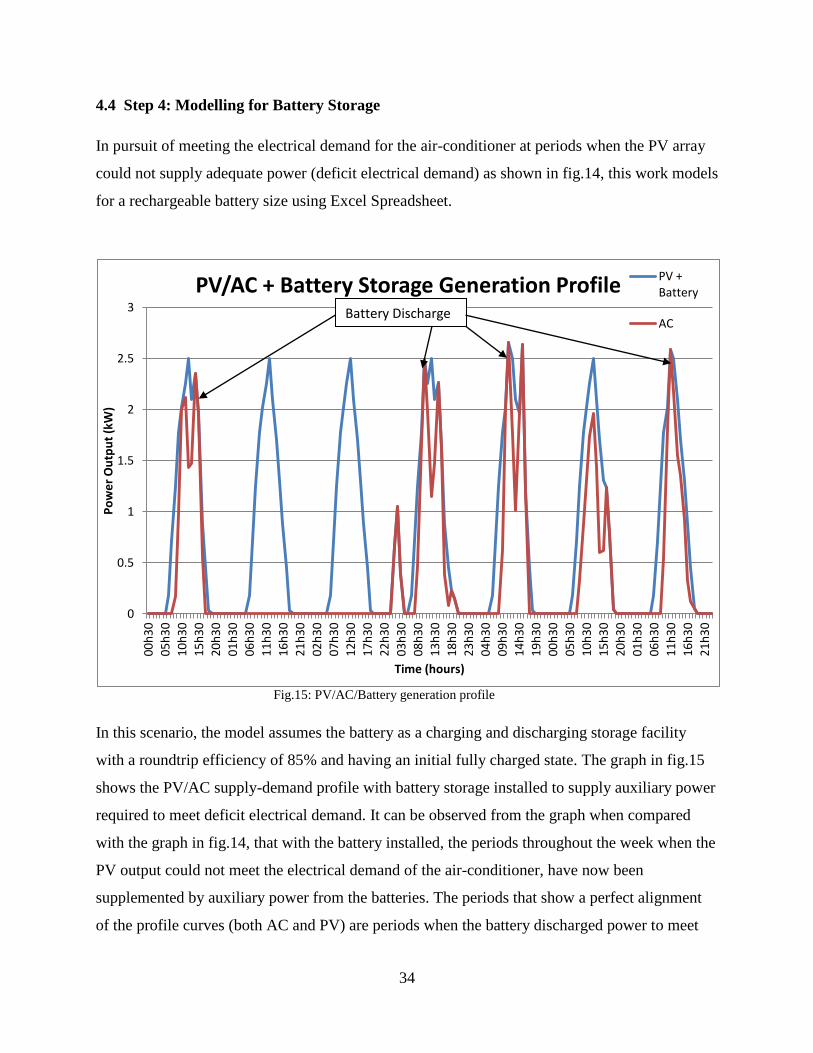
In pursuit of meeting the electrical demand for the air-conditioner at periods when the PV array
could not supply adequate power (deficit electrical demand) as shown in fig.14, this work models
for a rechargeable battery size using Excel Spreadsheet.
Fig.15: PV/AC/Battery generation profile
In this scenario, the model assumes the battery as a charging and discharging storage facility
with a roundtrip efficiency of 85% and having an initial fully charged state. The graph in fig.15
shows the PV/AC supply-demand profile with battery storage installed to supply auxiliary power
required to meet deficit electrical demand. It can be observed from the graph when compared
with the graph in fig.14, that with the battery installed, the periods throughout the week when the
PV output could not meet the electrical demand of the air-conditioner, have now been
supplemented by auxiliary power from the batteries. The periods that show a perfect alignment
of the profile curves (both AC and PV) are periods when the battery discharged power to meet
0
0.5
1
1.5
2
2.5
3
00
h3
0
05
h3
0
10
h3
0
15
h3
0
20
h3
0
01
h3
0
06
h3
0
11
h3
0
16
h3
0
21
h3
0
02
h3
0
07
h3
0
12
h3
0
17
h3
0
22
h3
0
03
h3
0
08
h3
0
13
h3
0
18
h3
0
23
h3
0
04
h3
0
09
h3
0
14
h3
0
19
h3
0
00
h3
0
05
h3
0
10
h3
0
15
h3
0
20
h3
0
01
h3
0
06
h3
0
11
h3
0
16
h3
0
21
h3
0
Po
we
r O
utp
ut
(kW
)
Time (hours)
PV/AC + Battery Storage Generation Profile PV + Battery
AC Battery Discharge

35
the deficit electrical demand of the AC. The battery discharges only 85% of excess power it
receives from charging by the PV module. Hence, from the graph, it is evident that all electrical
load required by the air-conditioner have been supplied by power outputs from both the solar PV
and batteries. The excess power supplied by the PV after recharging the batteries was exported to
grid and there was no need for grid import.
4.4.1 Battery Capacity
Having modeled for the power supply profile (PV + Batteries) to meet the electrical demand
(Air-Conditioner), Excel spreadsheet was used to quantify the maximum load (deficit electrical
demand) that the battery will be required to supply for a certain discharge period and this load
from the results analysis was 2.11kW. Most lead acid batteries have depth of discharge cycles of
80%, 50%, 20% and 10%. “Battery life is directly related to how deep the battery is cycled each
time. If a battery is discharged to 50% every day, it will last about twice as long as if it is cycled
to 80% and if it is cycled to only 10% depth of discharge, it will last about 5 times as long as one
cycled to 50%” (Born, 2000). Thus, a battery selection of 20% depth of discharge was selected in
pursuit of having a long battery lifespan.
In this model, the maximum depth of discharge of 20% equals the maximum load. i.e.
D.O.D = 20% = 2.11kW. However, since batteries are quantified with respect to time; then,
D.O.D = 20% = 2.11kWh = 2110Wh. An assumption of a nominal voltage of 24V was applied.
The maximum discharge capacity based on a 20% depth of discharge is
= 88Ah.
It is important to note that 88Ah represents the maximum discharge capacity which is just 20%
of the total battery capacity. Hence, the overall battery capacity required to meet the deficit
electrical demand for the air-conditioner is
= 440Ah.
36
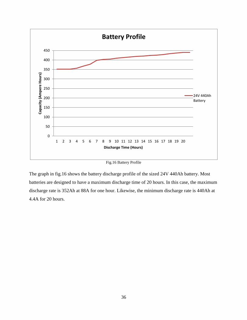
Fig.16 Battery Profile
The graph in fig.16 shows the battery discharge profile of the sized 24V 440Ah battery. Most
batteries are designed to have a maximum discharge time of 20 hours. In this case, the maximum
discharge rate is 352Ah at 88A for one hour. Likewise, the minimum discharge rate is 440Ah at
4.4A for 20 hours.
0
50
100
150
200
250
300
350
400
450
1 2 3 4 5 6 7 8 9 10 11 12 13 14 15 16 17 18 19 20
Cap
acit
y (A
mp
ere
Ho
urs
)
Discharge Time (Hours)
Battery Profile
24V 440Ah Battery
37
CHAPTER 5: Discussion
The steps required for the research methodology of this work have been carried out and the
results from the modelling and simulation analysis show that to meet the cooling demand for the
75 square metre ground floor office of a building in Lagos, Nigeria, without grid connection, an
off-grid cooling system made up of ;
an air-conditioning unit having a maximum cooling capacity of 10.55kW and a C.O.P
of 3.52
a 23 square metre PV array (which consists of 12, 1.9 square metres, PV modules with
each module having a generation capacity of 300W) having a generation capacity of
2.5kW with an efficiency of 15.63%
a series-parallel connection of a battery size of 24V 440Ah
will need to be installed. For this kind of installation to be made in practice, several logistics will
need to be taken into consideration. It is noteworthy to understand that this proposed off-grid
cooling system will only meet the cooling demand of one of the offices located on the ground
floor amongst other offices, coupled with other offices located on different floors within the
same building.
A practical view of the installation of this off-grid cooling system will require an external land-
mass area (at least 23m2) for the PV installation, and an internal space for the battery storage.
From the standpoint of a microscopic view, a long-lasting solution can be said to have been
provided to meet the cooling demand for an office. However, the applicability of this solution in
terms of large scale deployment in other offices within the same building undermines the
technical feasibility of the off-grid cooling system. Office buildings if built to several floors
usually have limited external space around it. Hence, for this proposed system to be deployed in
multiple offices, large land-spaces will be required for installations of all the solar PVs that will
be required to power the air-conditioners in all the offices. This will definitely be a huge task to
achieve and as a result, the plausibility of the cooling system being adopted by office occupants
as an off-grid solution to meeting cooling demand seems unlikely.

38
An economic perspective of this proposed off-grid system indicates a high cost of procurement
without a convincing incentive of offsetting unit electricity costs in the long run. A review of
several literatures on solar PV potentials for Nigeria have all indicated prevalent problems
associated with the long-term use of solar PV sources to meet energy demand. The main drive
behind the championing of sustainability of energy systems lies under the aegis of cost
effectiveness. This proposed solution, despite the fact that it cannot be said to be cost-effective in
terms of capital costs, offers no plausibility of being cost effective in the long run, as subsequent
research has shown solar PV to be unreliable for long term usage in Nigeria.
The steps carried out in the research methodology i.e. modelling and simulation can be said to be
simplistic rather than detailed. The unavailability of pertinent data that will enhance detailed
modelling resulted in the use of reasonable assumptions where necessary. For instance, the
electrical demand for the air-conditioner was derived by using an average annual C.O.P value of
3.52kW extracted from manufacturer data which ought not to have been so, as C.O.P values
change with respect to variations in ambient temperature. Also, the calculations used to evaluate
the surface area of the PV array neglected several thermal properties like cell temperature of the
module, surface emissivity and absorbtivity values, and the nominal input and output current and
voltage. The battery sizing procedure on Excel Spreadsheet, did not take into consideration, the
lifecycle period of the batteries, self-discharging of the batteries and the performance of the
charge controller in terms of preventing overcharging and deep discharging. The performance of
the D.C-A.C inverter in terms of conversion of D.C power supplied by the PV and batteries to
A.C was also neglected.
Building the model from scratch on ESP-r had limitations during the selection of parameters on
the software. Firstly, the weather file used to determine the variations in cooling demand was not
for Lagos, Nigeria but Accra, Ghana. Also, the most of the material properties used for the
building constructions were the ones available on the software. Although, ESP-r gives room for
creation of new materials, research in the literature on Nigerian buildings shows a prevalent
absence of pertinent data for properties of materials used in building construction. This limited
the model construction to selection of material properties within the context of the software. As a
result of neglecting vital parameters and making several assumptions, the results gotten from the
research methodology can be said to be idealistic and likened to that derived from a scope study.
39
CHAPTER 6: Conclusion and Future Recommendations
The aim of this project is to model and carry out simulations of a solar PV powered air-
conditioner to meet the cooling demand for a single occupant office located on the ground floor
of a building in Lagos, Nigeria. The modelling and simulations was done with the use of ESP-r
software and Excel Spreadsheet. The results gotten from the simulation for the cooling demand
and PV with batteries have been analysed, most of which have shown to be idealistic due to
limitations in availability of pertinent data and subsequent assumptions of key parameters.
More detailed modeling can be carried out in the building procedure using ESP-r to determine a
more precise result for cooling load. This could be achieved by creating a weather file for Lagos,
Nigeria either on ESP-r or on similar compatible software. Variations in the occupancy schedules
for different days of the week can also enhance the accuracy of the results for the required
cooling demand. Neglected factors like shading and insolation, and lighting controls can aid in
producing realistic values for the cooling load. Also, research could be carried out to document
the material properties used in Nigerian building constructions as this data is currently
unavailable.
The plausibility of adapting the proposed off-grid cooling system to different buildings and
several locations within the country (for example, rural areas) can also be investigated. Daily or
weekly values of solar insolation for Lagos as well as data showcasing the variations in solar
geometry of the location, if made available, can help in estimating a high degree of accuracy for
sizing the PV array.
It is noteworthy to understand that upshot from the results analysis of this project is not to
undermine or discard the possibility of achieving the goals behind the project but to evince the
limitations that needs to be surmounted in meeting these goals. The goals behind the project
which is to reduce the load on the weak grid infrastructure and offset all unit electricity costs
associated with cooling demand can be said to be farfetched as a result of practical limitations in
making the proposed off-grid cooling system technically feasible and economically viable. These
limitations can be ameliorated if the aforementioned suggestions that can enhance detailed
modelling are taken into consideration.
40
REFERENCES
Mbamali, I. and Okotie, A.J. (2012), An assessment of the threats and opportunities of
globalization on building practice in Nigeria. American International Journal of Contemporary
Research, 2(4): 143-150
Iwaro, J. and Mwasha, A. (2010), Implications of building energy standard for sustainable
energy efficient design in buildings. International Journal of Energy and Environment,
1(5): 745-756
Lawal, A.F. and Ojo, O.J. (2011), Assessment of thermal performance of residential buildings in
Ibadan land, Nigeria. Journal of Emerging Trends in Engineering and Applied Sciences.
2(4): 581-586
Abdul-Majid, N.H. and Hussaini, I.U. (2011), Housing design practice and energy efficiency and
consideration in Nigeria. Third International Conference on Applied Energy. Perugia, Italy, May
16-18, pp. 1459-1470
Energy Commission of Nigeria (2008). Assessment of Energy Options and Strategies for
Nigeria: Energy Demand, Supply and Environmental Analysis for Sustainable Energy
Development (2000-2030). Report No. ECN/EPA/2008/01.
National Technical Working Group on Energy Sector (2009). Report of the vision 2020.
pp.4-177
Ukoha, O.M. and Beamish, J.O. (1997), Assessment of residents` satisfaction with public
housing in Abuja, Nigeria. Habitat International, 21(4):445-460
Mbamali, I., Aiyetan, O.A. and Kehinde, J.O. (2005), Building design for buildability: an
investigation of the current practice in Nigeria, Building and Environment, 40(9):1267-1274
Oyedepo, S.O. (2012), On energy for sustainable development in Nigeria. Renewable and
Sustainable Energy Reviews, 16(5):2583-2598
Sivak, M. (2009), Potential energy demand for cooling in the 50 largest metropolitan areas of the
world: Implications for developing countries. Energy Policy, 37(4):1382-1384

41
Njoku, H.O. (2013), Solar photovoltaic potential in Nigeria. American Society of Civil
Engineers. DOI: 10.1061/(ASCE)EY.1943-7897.0000145, pp. 1-7
Ismail, O.S., Ajide, O.O. and Akingbesote, F. (2012), Performance assessment of installed solar
PV system: A case study of Oke-Agunla in Nigeria. Engineering, 4: 453-458
Oparaku, O.U. (2002), Photovolatic systems for distributed power supply in Nigeria. Renewable
Energy, 25:31-40
Adaramola, M.S. (2014), Viability of grid-connected solar PV energy systems in Jos, Nigeria.
International Journal of Electrical Power &Energy Systems, 61:64-69
Oko, C.O.C., Diemuodeke, E.O., Omunakwe, N.F., and Nnamdi, E. (2012), Design and
economic analysis of a photovoltaic system: A case study. International Journal of renewable
Energy Development, 1(3):65-73
Obanor, A.I. and Egware, H.O. (2013), Reflections on the usage of air-conditioning systems in
Nigeria. American Journal of Engineering Research, 2(12):414-419
Abimaje, J. and Akingbohungbe, D.O. (2013), Energy efficient housing as a mitigating option
for climate change in Nigeria. International Journal of Energy and Environmental Research,
1(1):16-22
Ibitoye, F.I. and Adenikinju, A. (2007), Future demand for electricity in Nigeria. Applied
Energy, 84:492-504
Born, F.J. (2001), Aiding renewable energy integration through complimentary demand-supply
matching. Unpublished Ph D thesis, Energy Systems Research Unit, University of Strathclyde.

42
Kasimu, S.Y. (2000), Financing options for solar PV enterprises in Nigeria. Paper presented at
the National Workshop on the Promotion of Business and Industrial Activities in Solar
Photovoltaic Power Systems in Nigeria.
Uyigwe, E., Agho, M., Edevbaro, A., Godfrey, O.O., Uyigwe, O.P. and Okungbowa, O.G.
(2009), Energy efficiency survey in Nigeria: A guide for developing policy and legislation.
Community Research and Development Centre. pp.3-37
43
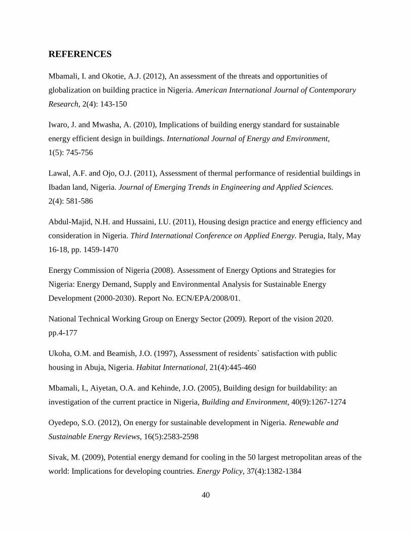
APPENDIX
Fig. 17 Solar PV powered Air- Conditioner (window unit)
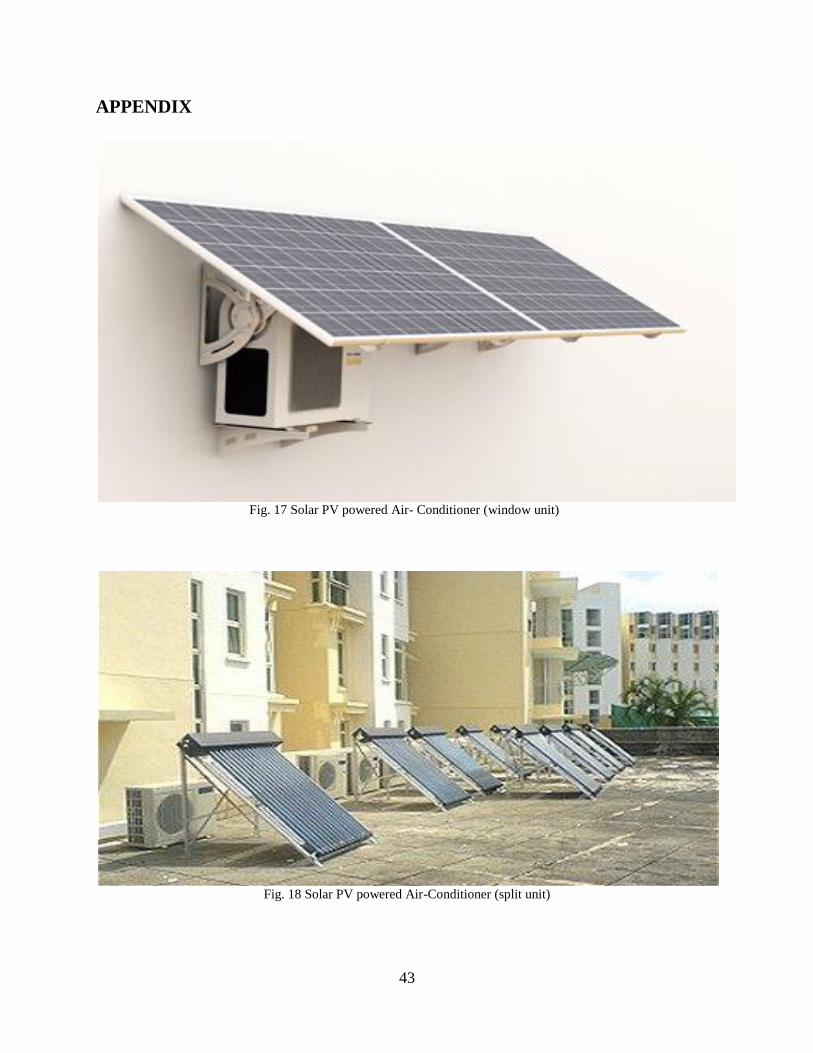
Fig. 18 Solar PV powered Air-Conditioner (split unit)