modeling magneto-rheological damper …umpir.ump.edu.my/4931/1/cd7317_70.pdf · menggunakan...
TRANSCRIPT

MODELING MAGNETO-RHEOLOGICAL DAMPER USING ANFIS METHOD
MOHD RIDZWAN B HJ RAMLI
Report submitted in partial fulfillment of the requirements
for the award of Bachelor’s Degree of Mechanical Engineering
Faculty of Mechanical Engineering
UNIVERSITI MALAYSIA PAHANG
JUNE 2012

vi
ABSTRACT
This thesis focused on the development Modeling Magneto-Rheological damper
using Adaptive Neuro-Fuzzy Inference System (ANFIS) method. Magneto-Rheological
(MR) damper is a semi-active control device and has been characterized by a set of non-
linear differential equations which represent a model of the MR damper. By using this
mathematical model, the force of the MR damper is directly solved to a given
displacement and applied current. However, solving the non-linear equations describing
the performance of the MR damper may be difficult or time consuming to predict a
required voltage. One of the methods to model the MR damper is using (ANFIS).It is
faster than the mathematical model for keeping the error small. ANFIS has been
effectively applied to model complex systems because of its great training process.

vii
ABSTRAK
Tesis ini tertumpu kepada Pemodelan pembangunan magneto-reologi peredam
menggunakan Adaptive Neuro Fuzzy Sistem Inferens (ANFIS) method.Magneto-reologi
(MR) peredam adalah alat kawalan semi-aktif dan telah dicirikan oleh satu set
persamaan pembeza bukan linear yang mewakili model peredam MR. Dengan
menggunakan model matematik ini, Daya peredam MR secara langsung diselesaikan
dengan jarak dan arus elektrik yang diberikan. Walau bagaimanapun, penyelesaian
persamaan bukan-linear yang menerangkan prestasi peredam MR mungkin sukar atau
mengambil masa yang lama untuk meramalkan voltan yang diperlukan. Salah satu
kaedah untuk memodelkan peredam MR menggunakan (ANFIS). Ia adalah lebih cepat
daripada model matematik untuk mengekalkan ralat kecil. ANFIS telah berkesan
digunakan untuk memodelkan sistem yang kompleks kerana proses latihan yang hebat.
.

viii
TABLE OF CONTENTS
PAGE
EXAMINER’S DECLARATION ii
SUPERVISOR’S DECLARATION iii
STUDENT’S DECLARATION iv
ACKNOWLEDGEMENT v
ABSTRACT vi
ABSTRAK vii
TABLE OF CONTENT x
LIST OF TABLES xi
LIST OF FIGURES xiv
LIST OF SYMBOLS xv
LIST OF ABBREVIATIONS xvi
CHAPTER 1 INTRODUCTION 1
1.1 Introduction 1
1.2 Project background 1
1.3 Problem statement 2
1.4 Objective 3
1.5 Scope of Project 3
CHAPTER 2 LITERATURE REVIEW 4
2.1 Introduction 4
2.2 MR fluid 4
2.3 Types of suspension 9
2.3.1 Passive suspension system 10 2.2.2 Active suspension system 11 2.2.3 Semi active suspension system 12
ix
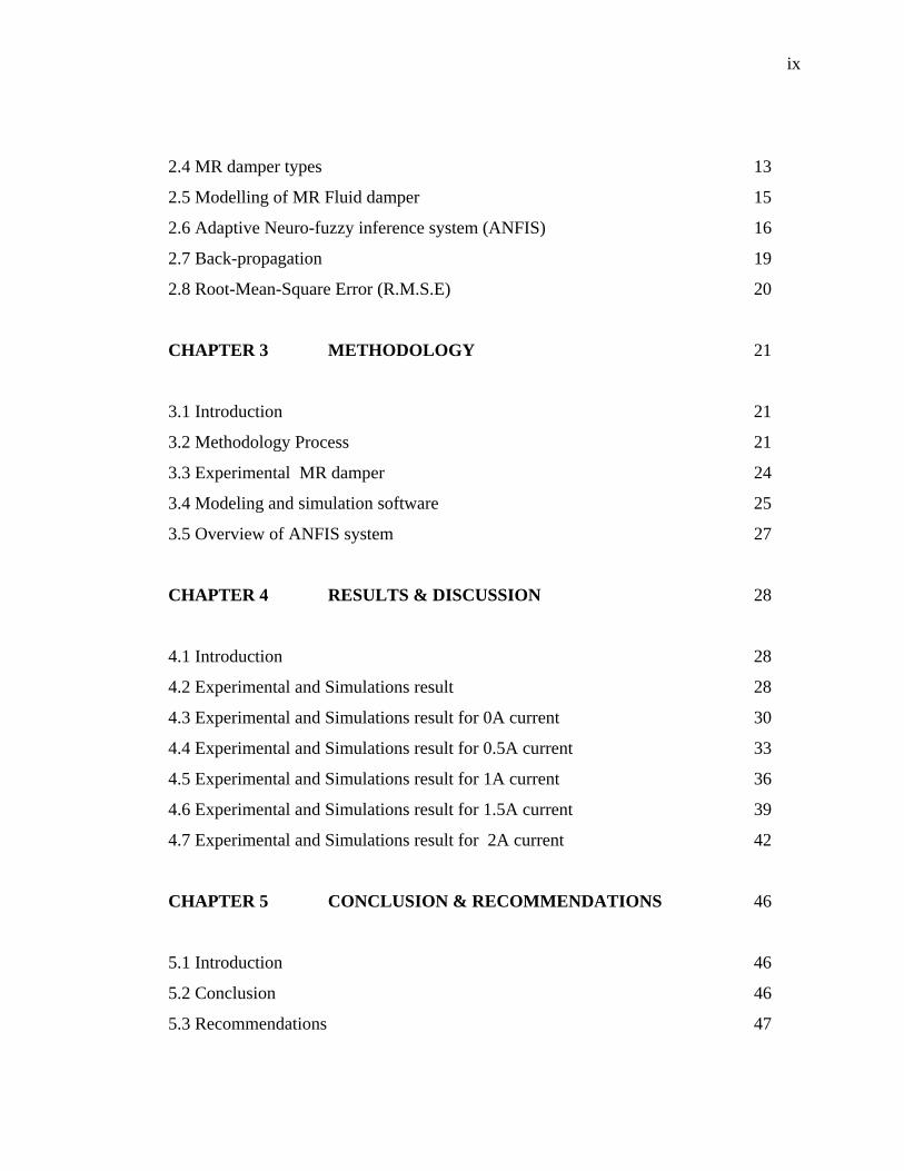
2.4 MR damper types 13
2.5 Modelling of MR Fluid damper 15
2.6 Adaptive Neuro-fuzzy inference system (ANFIS) 16
2.7 Back-propagation 19
2.8 Root-Mean-Square Error (R.M.S.E) 20
CHAPTER 3 METHODOLOGY 21
3.1 Introduction 21
3.2 Methodology Process 21
3.3 Experimental MR damper 24
3.4 Modeling and simulation software 25
3.5 Overview of ANFIS system 27
CHAPTER 4 RESULTS & DISCUSSION 28
4.1 Introduction 28
4.2 Experimental and Simulations result 28
4.3 Experimental and Simulations result for 0A current 30
4.4 Experimental and Simulations result for 0.5A current 33
4.5 Experimental and Simulations result for 1A current 36
4.6 Experimental and Simulations result for 1.5A current 39
4.7 Experimental and Simulations result for 2A current 42
CHAPTER 5 CONCLUSION & RECOMMENDATIONS 46
5.1 Introduction 46
5.2 Conclusion 46
5.3 Recommendations 47

x
REFERENCES 48
APPENDICES 51
A1 GANTT CHART FYP 1 52
A2 GANTT CHART FYP 2 53
xi
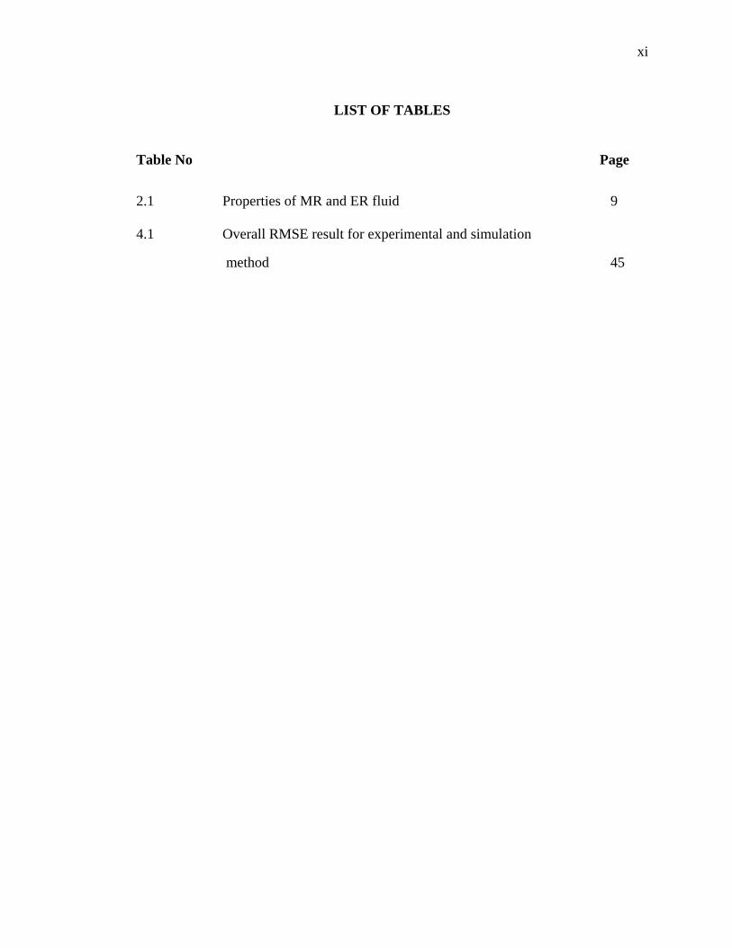
LIST OF TABLES
Table No Page
2.1 Properties of MR and ER fluid 9 4.1 Overall RMSE result for experimental and simulation
method 45
xii
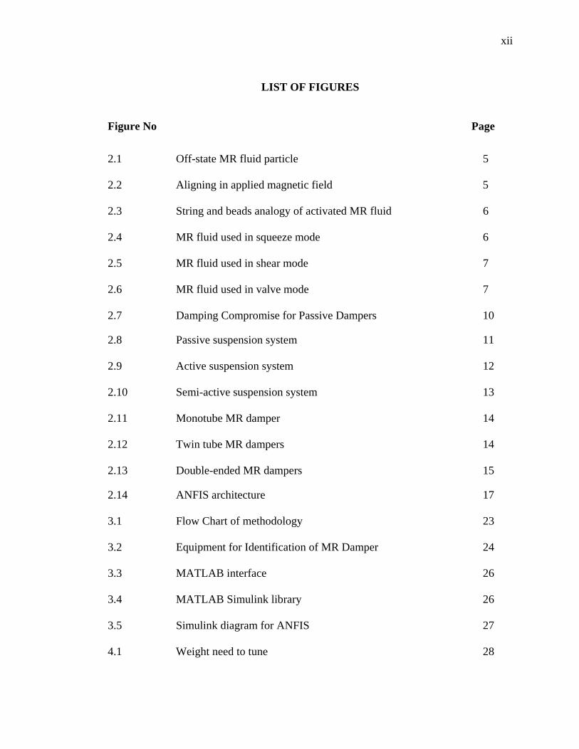
LIST OF FIGURES
Figure No Page
2.1 Off-state MR fluid particle 5 2.2 Aligning in applied magnetic field 5 2.3 String and beads analogy of activated MR fluid 6 2.4 MR fluid used in squeeze mode 6 2.5 MR fluid used in shear mode 7 2.6 MR fluid used in valve mode 7 2.7 Damping Compromise for Passive Dampers 10
2.8 Passive suspension system 11 2.9 Active suspension system 12 2.10 Semi-active suspension system 13 2.11 Monotube MR damper 14 2.12 Twin tube MR dampers 14 2.13 Double-ended MR dampers 15
2.14 ANFIS architecture 17 3.1 Flow Chart of methodology 23 3.2 Equipment for Identification of MR Damper 24 3.3 MATLAB interface 26 3.4 MATLAB Simulink library 26 3.5 Simulink diagram for ANFIS 27 4.1 Weight need to tune 28

xiii
4.2 Learning rate need to tune 29 4.3 Experimental graph for 0A current 30 4.4 Displacement graph for 0A current 30 4.5 Simulation block diagram using experimental data and
0A current 31 4.6 Simulation and experimental graph for 0A current 31
4.7 Error graph for experimental and simulation 32 4.8 Experimental graph for 0.5A current 33 4.9 Displacement graph for 0.5A current 33 4.10 Simulation block diagram using experimental data and
0.5A current 34 4.11 Simulation and experimental graph for 0.5A current 34 4.12 Error graph for experimental and simulation 35 4.13 Experimental graph for 1A current 36 4.14 Displacement graph for 1A current 36 4.15 Simulation block diagram using experimental data and
1A current 37 4.16 Simulation and experimental graph for 1A current 37 4.17 Error graph for experimental and simulation 38
4.18 Experimental graph for 1.5A current 39 4.19 Displacement graph for 1.5A current 39 4.20 Simulation block diagram using experimental data and
1.5A current 40 4.21 Simulation and experimental graph for 1.5A current 40 4.22 Error graph for experimental and simulation 41
xiv
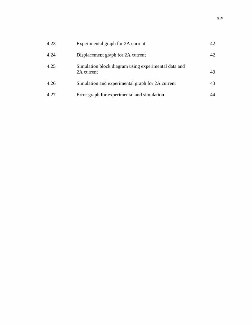
4.23 Experimental graph for 2A current 42 4.24 Displacement graph for 2A current 42 4.25 Simulation block diagram using experimental data and
2A current 43 4.26 Simulation and experimental graph for 2A current 43 4.27 Error graph for experimental and simulation 44
xv
LIST OF SYMBOLS
Fanfis - ANFIS force Factual - Actual force from experimental N - No of data x - Body displacement u - Wheel displacement
xvi
LIST OF ABBREVIATIONS
ANFIS - Adaptive Neuro-fuzzy inference system MR - Magneto-Rheological RMSE - Root Mean Square Error MATLAB - Matrix Laboratory
CHAPTER 1
INTRODUCTION
1.1 INTRODUCTION
The purpose of this chapter is to present the project background and starting
point for the progress in this project. The problem statements and objective of this
project are discussed. The chapter end with the scopes of the project.
1.2 PROJECT BACKGROUND
In recent years, a family of fluids known as Magneto-rheological (MR) fluids
has gained increased recognition for its many applications. During the late 1940's and
early 1950's, there was a flurry of interest in MR devices (Jolly et al., 1998). This
interest, however, soon died out, probably due to limitations in sealing technology and
difficulties in preventing caking and particle sedimentation within the fluid. Magneto-
rheological dampers of various applications have been and continue to be developed.
Many structures, such as automotive vehicles, tall buildings, robotic manipulator arms
and flexible spacecraft have already been designed using magneto-rheological damper.
The most popular of these devices are MR damper, especially as automotive shock
absorber. For instance, Lord Corporation has been developing MR fluids and devices
since the early 1990's. In the mid 1990's, Lord Corporation began manufacturing an MR
damper line called "Motion Master”. These dampers have found their way into truck seat
suspensions and prosthetic legs. Shortly after, Lord developed a rotary MR brake for
2
treadmill applications, as well as damper for automobile use (Lord, 1999). The
automotive shock absorber has been shown to be a very important contributor to the ride
and road handling of a vehicle. For ride comfort, shock absorber with a ‘soft’ setting are
required to dissipate shock energy from the road, while a ‘hard’ setting is required for
good vehicle handling. These conflicting characteristics of ride comfort and road
holding is a major challenge to automotive shock absorber designer. Tuning of
conventional hydraulic shock absorbers normally involves the physical adjustments of
the settings of various valves located inside the piston. Also conventional absorbers will
have a constant setting throughout their lifetime, and hence will not be able to operate
satisfactorily in a wide range of road conditions. It is for these reasons that semi-active
systems like MR dampers have attracted the attention of suspension designers and
researchers. MR dampers are semi- active control devices that use MR fluids to produce
controllable dampers. They potentially offer highly reliable operation and can be viewed
as fail-safe in that they become passive dampers if the control hardware malfunction.
The advantage of MR dampers over conventional dampers are that they are simple in
construction, compromise between high frequency isolation and natural frequency
isolation, they offer semi-active control, use very little power, have very quick response,
has few moving parts, have a relax tolerances and direct interfacing with electronics.
MR fluids are controllable fluids belonging to the class of active materials that have the
unique ability to change dynamic yield stress when acted upon by an electric or
magnetic field, while maintaining viscosity relatively constant. This property can be
utilized in MR damper where the damping force is changed by changing the rheological
properties of the fluid magnetically. The conclusions, advantages of Magneto
rheological damper are the need very less control power, have simple construction,
quick response to control signals and few moving parts.
1.3 PROBLEM STATEMENT
MR damper is a semi-active control device and has been characterized by a set of
non-linear differential equations which represent a model of the MR damper. By using
the mathematical model, the force of the MR damper is directly solved to a given

3
displacement and applied current. However, given enough time and effort, it may be
possible to perfectly model behaviour of a complex system through the use of traditional
modelling techniques (Yen and Langari, 1999). One of the methods to model the MR
damper is using Adaptive neuro-fuzzy inference system (ANFIS). ANFIS uses a hybrid
learning algorithm that combines the backpropagation gradient descent and least square
methods to create fuzzy inferences system whose membership functions are iteratively
adjusted according to a given set of input and output data (Kyle and Paul, 2005). The
ANFIS mathematical equation will be simulating into MATLAB program. It is faster
than the traditional mathematical model for keeping the error small. ANFIS has been
effectively applied to model complex systems because of its great training process.
1.4 OBJECTIVE
The primary objectives of this thesis is
I. To model the non linear of MR damper using ANFIS method.
II. To compare the result between experimental data and simulation using Root
Mean Square Error (RMSE).
1.5 SCOPE The scope for this thesis is
I. To understands MR damper characteristic
II. Modelling MR damper using ANFIS method.
III. Run code to obtain the data to analyzed using MATLAB
4
CHAPTER 2
LITERATURE REVIEW
2.1 Introduction
This chapter is conducted to investigate the past research done in any areas that
related in this project. This chapter starts with the meaning of each word in the project
title. Previous researches are then reviewed and discussed briefly in order to understand
more about projects and also gathering useful information.
2.2 MR Fluid
Magneto-rheological fluids are fluids that exhibit a change in rheological
properties when a magnetic field is induced through the fluid (Jolly et al., 1998). In
essence, the fluid’s flow characteristics, namely apparent viscosity change. Jacob
Rainbow, who worked for US National Bureau of Standards, first introduced MR fluids
in the 1940s (Jolly et al., 1998). MR fluid consists of a liquid carrier, ferrous particles on
the order of a few microns in diameter, and surfactant additives that are used to
discourage particle settling. Three different carrier fluids are currently used, namely
hydrocarbon-based oil, silicon oil, and water (Jolly et al., 1998). When exposed to a
magnetic field, the ferrous particles that are dispersed throughout the fluid form
magnetic dipoles. These magnetic dipoles align themselves along lines of magnetic flux,
as shown in Figure 2.1

5
Figure 2.1 Off-state MR fluid particle
Source: John (2003)
Figure 2.2 Aligning in applied magnetic field
Source: John (2003)
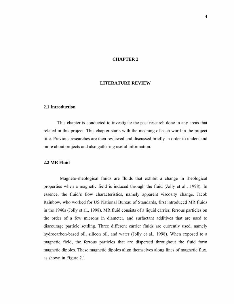
The dipoles align parallel to the induced magnetic flux lines to form chain-like structure
of iron particle between the north and South Pole (Lord, 1999). On a larger scale, this
reordering of ferrous dipole particles can be visualized as a very large number of
microscopic beads that are threaded onto a very thin string as is shown in Figure 2.3.
One can picture this thin string stretching from one magnetic pole to the other and
perpendicular to each paramagnetic pole surface.
6
Figure 2.3 String and beads analogy of activated MR fluid
Source: John (2003)
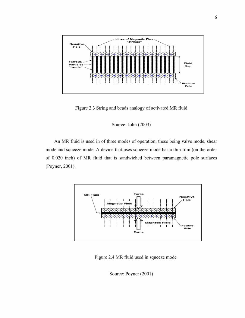
An MR fluid is used in of three modes of operation, these being valve mode, shear
mode and squeeze mode. A device that uses squeeze mode has a thin film (on the order
of 0.020 inch) of MR fluid that is sandwiched between paramagnetic pole surfaces
(Poyner, 2001).
Figure 2.4 MR fluid used in squeeze mode
Source: Poyner (2001)
7
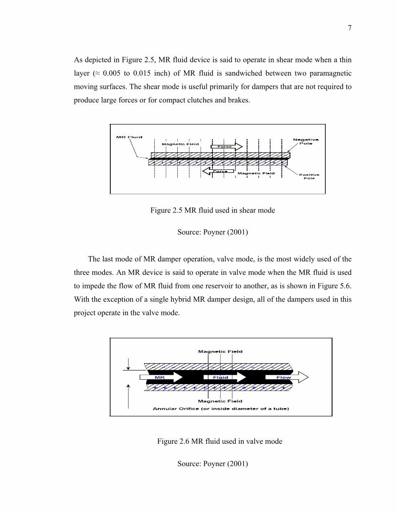
As depicted in Figure 2.5, MR fluid device is said to operate in shear mode when a thin
layer (≈ 0.005 to 0.015 inch) of MR fluid is sandwiched between two paramagnetic
moving surfaces. The shear mode is useful primarily for dampers that are not required to
produce large forces or for compact clutches and brakes.
Figure 2.5 MR fluid used in shear mode
Source: Poyner (2001)
The last mode of MR damper operation, valve mode, is the most widely used of the
three modes. An MR device is said to operate in valve mode when the MR fluid is used
to impede the flow of MR fluid from one reservoir to another, as is shown in Figure 5.6.
With the exception of a single hybrid MR damper design, all of the dampers used in this
project operate in the valve mode.
Figure 2.6 MR fluid used in valve mode
Source: Poyner (2001)

8
The advantages of MR fluid technology relative to conventional and electro-mechanical
solutions are summarised as follows (Metered, 2010):
• Quick response time (less than 10 milliseconds).
• Consistent efficacy across extreme temperature variations.
• Continuously variable control damping.
• High dissipative force that is less dependent on velocity compared to passive
dampers.
• Greater energy density.
• Inherent system stability (no active forces generated).
• Minimal power usage (typically 12V , 1 A. max. current that can fail-safe to
battery backup, which can, in turn, fail-safe to passive damping mode).
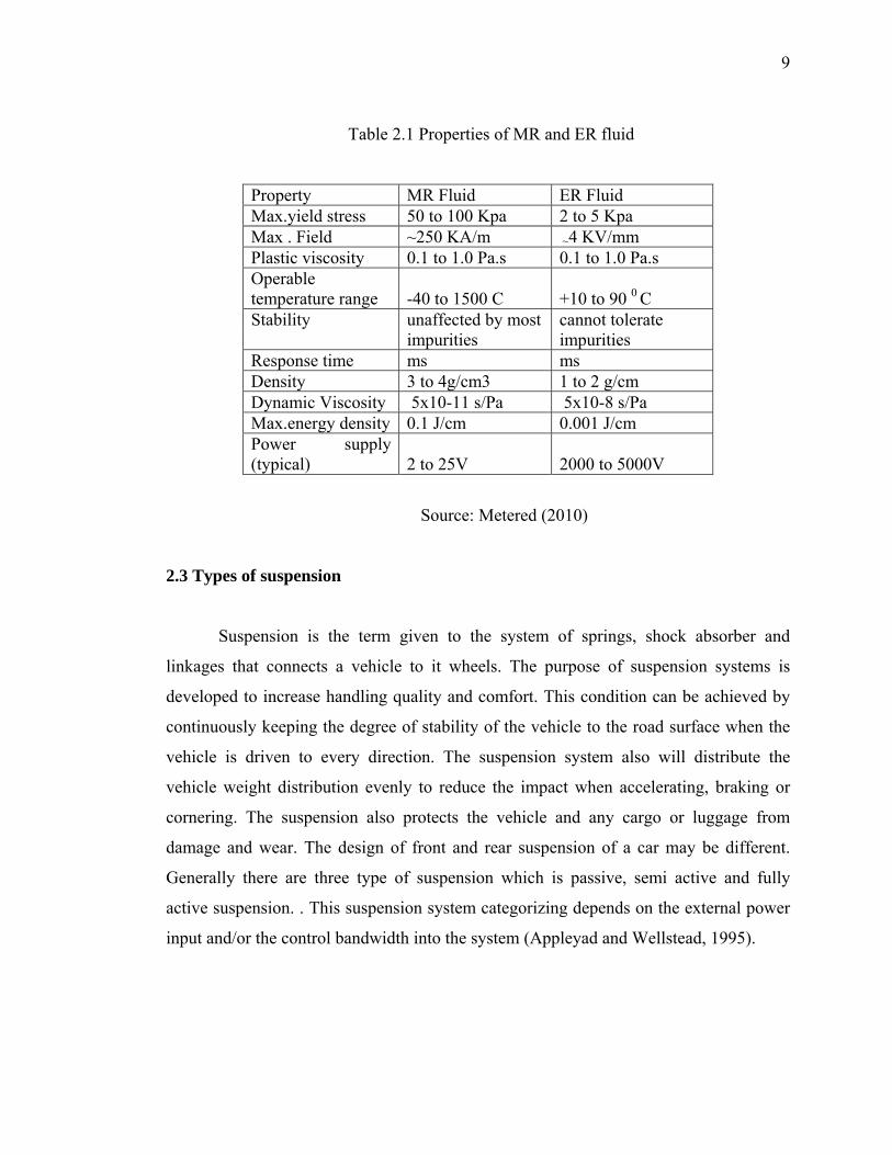
MR fluids are quite similar to Electro rheological (ER) fluids in composition. MR
and ER fluids contain carbonyl iron on the order of a few microns in size. From table 2.1
MR fluids demonstrate very high yield strength of 20 to 50 times the strength of ER
fluids. Furthermore, because the magnetic polarization mechanism is unaffected by
temperature, the performance of MR based devices is relatively insensitive to
temperature over a broad temperature range (including the range for automotive use)
(Marin et al., 2004). MR fluids can operate at temperature from -40 to 150o C with only
slight variation in the yield stress (Carlson et al., 1994), in contrast to ER fluids
(restricted to a range of 10 to 90 o C) .MR fluids are significantly less sensitive to
impurities or contaminants such as are commonly encountered during manufacturing
and usage (Wang and Liao, 2005).MR technology can provide flexible control
capabilities in designs that are far less complicated and more reliable than those based
on ER technology (Dyke, 1996) . Moreover, as can be seen from Table 2.1, in contrast to
ER fluids, MR fluids can be readily operated from a low voltage (e.g., ~12–24V),
current-driven power supply outputting only ~1–2 amps. From the data MR fluids are
more effective for use in controllable fluid dampers considered to ER fluids.
9
Table 2.1 Properties of MR and ER fluid
Property MR Fluid ER Fluid Max.yield stress 50 to 100 Kpa 2 to 5 Kpa Max . Field ~250 KA/m ~4 KV/mm Plastic viscosity 0.1 to 1.0 Pa.s 0.1 to 1.0 Pa.s Operable temperature range -40 to 1500 C +10 to 90 0 C Stability unaffected by most cannot tolerate impurities impurities Response time ms ms Density 3 to 4g/cm3 1 to 2 g/cm Dynamic Viscosity 5x10-11 s/Pa 5x10⁻⁸ s/Pa Max.energy density 0.1 J/cm 0.001 J/cm Power supply (typical) 2 to 25V 2000 to 5000V
Source: Metered (2010)
2.3 Types of suspension
Suspension is the term given to the system of springs, shock absorber and
linkages that connects a vehicle to it wheels. The purpose of suspension systems is
developed to increase handling quality and comfort. This condition can be achieved by
continuously keeping the degree of stability of the vehicle to the road surface when the
vehicle is driven to every direction. The suspension system also will distribute the
vehicle weight distribution evenly to reduce the impact when accelerating, braking or
cornering. The suspension also protects the vehicle and any cargo or luggage from
damage and wear. The design of front and rear suspension of a car may be different.
Generally there are three type of suspension which is passive, semi active and fully
active suspension. . This suspension system categorizing depends on the external power
input and/or the control bandwidth into the system (Appleyad and Wellstead, 1995).
10
2.3.1 Passive suspension system
A passive suspension system is one which the characteristics of the components
(springs and dampers) are fixed. An early design for automobile suspension systems
focused on unconstrained optimization for passive suspension system which indicates
the desirability of low suspension stiffness, reduced un-sprung mass, and optimum
damping ratio for the best controllability (Thompson, 1976). The spring is chosen based
solely on the weight of the vehicle, while the damper is the component that defines the
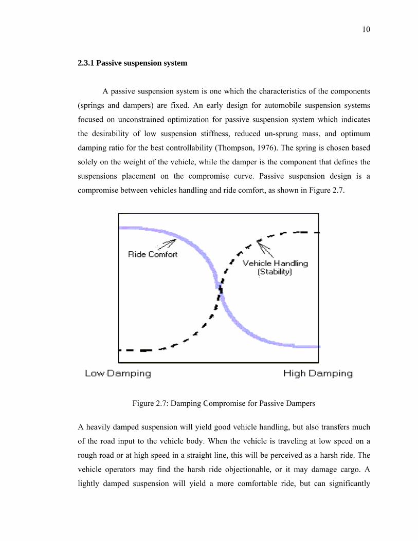
suspensions placement on the compromise curve. Passive suspension design is a
compromise between vehicles handling and ride comfort, as shown in Figure 2.7.
Figure 2.7: Damping Compromise for Passive Dampers
A heavily damped suspension will yield good vehicle handling, but also transfers much
of the road input to the vehicle body. When the vehicle is traveling at low speed on a
rough road or at high speed in a straight line, this will be perceived as a harsh ride. The
vehicle operators may find the harsh ride objectionable, or it may damage cargo. A
lightly damped suspension will yield a more comfortable ride, but can significantly
11
reduce the stability of the vehicle in turns, lane change maneuvers, or in negotiating an
exit ramp. Good design of a passive suspension can to some extent optimize ride and
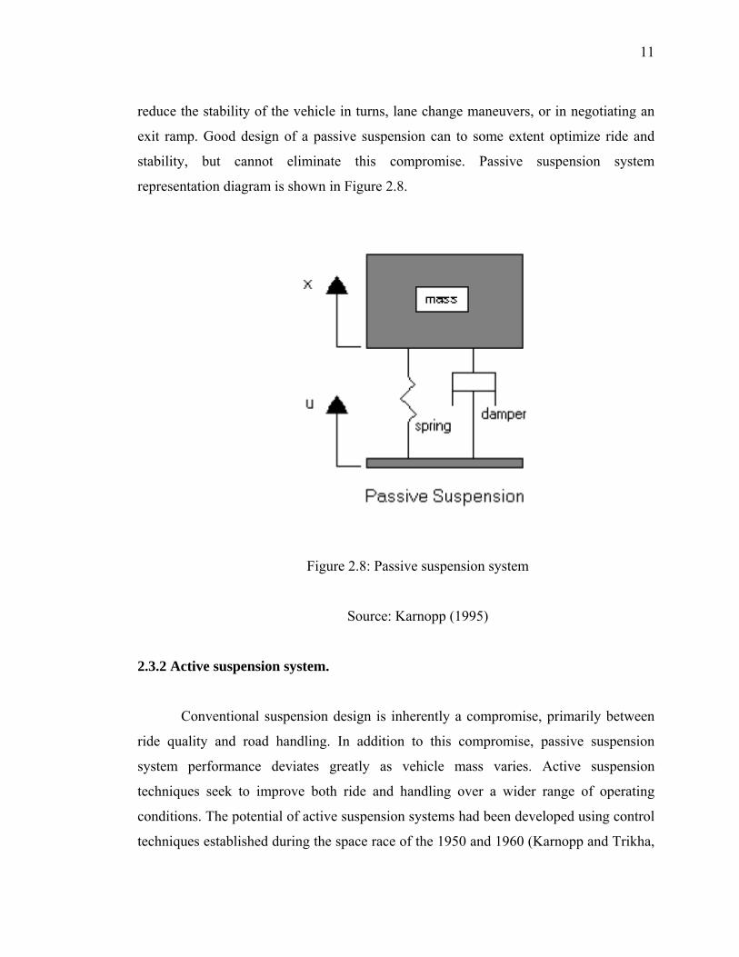
stability, but cannot eliminate this compromise. Passive suspension system
representation diagram is shown in Figure 2.8.
Figure 2.8: Passive suspension system
Source: Karnopp (1995)
2.3.2 Active suspension system.
Conventional suspension design is inherently a compromise, primarily between
ride quality and road handling. In addition to this compromise, passive suspension
system performance deviates greatly as vehicle mass varies. Active suspension
techniques seek to improve both ride and handling over a wider range of operating
conditions. The potential of active suspension systems had been developed using control
techniques established during the space race of the 1950 and 1960 (Karnopp and Trikha,

12
1969). In active suspension, the damper is replaced by a force actuator. The advantage
the force actuator can generate a force in any direction, while a passive damper can only
dissipate energy (Emmanuel, 2003). A good control scheme can result in a much better
compromise between ride comfort and vehicle stability compared to passive suspension
(Alleyne and Hendrick, 1995). Active suspension can also easily reduce the pitch and
the roll of the vehicle. However, active suspensions have many disadvantages and are
too expensive for wide spread commercial use because of their complexity and large
power requirements. Also, a failure of the force actuator could make the vehicle very
unstable and therefore dangerous to drive. Active suspension system representation in
diagram is shown in figure 2.9.
Figure 2.9: Active suspension system
Source: Karnopp (1995)
2.3.3 Semi-Active suspension system.
The idea of semi-active suspension control was introduced in the early 1970’s in the
form of variable damping. Since then, variable damping schemes have been the
predominant form of semi-active suspension control. In early semi-active suspension
system, regulating of the damping force can be achieved by utilizing the control damper