modeling a helical-coil steam generator in relap5-3d for the next generation nuclear plant
DESCRIPTION
Modeling a Helical-Coil Steam Generator in RELAP5-3D for the Next Generation Nuclear PlantTRANSCRIPT
INL/EXT-10-19621
Modeling a Helical-coil Steam Generator in RELAP5-3D for the Next Generation Nuclear Plant
Nathan V. Hoffer Piyush Sabharwall Nolan A. Anderson January 2011

DISCLAIMER This information was prepared as an account of work sponsored by an
agency of the U.S. Government. Neither the U.S. Government nor any agency thereof, nor any of their employees, makes any warranty, expressed or implied, or assumes any legal liability or responsibility for the accuracy, completeness, or usefulness, of any information, apparatus, product, or process disclosed, or represents that its use would not infringe privately owned rights. References herein to any specific commercial product, process, or service by trade name, trade mark, manufacturer, or otherwise, does not necessarily constitute or imply its endorsement, recommendation, or favoring by the U.S. Government or any agency thereof. The views and opinions of authors expressed herein do not necessarily state or reflect those of the U.S. Government or any agency thereof.
INL/EXT-10-19621
Modeling a Helical-coil Steam Generator in RELAP5-3D for the Next Generation Nuclear Plant
Nathan V. Hoffer Piyush Sabharwall Nolan A. Anderson
January 2011
Idaho National Laboratory Next Generation Nuclear Plant Project
Idaho Falls, Idaho 83415
Prepared for the U.S. Department of Energy Office of Nuclear Energy
Under DOE Idaho Operations Office Contract DE-AC07-05ID14517


v
ABSTRACT
Options for the primary heat transport loop heat exchangers for the Next Generation Nuclear Plant (NGNP) are currently being evaluated. A helical-coil steam generator is one heat-exchanger design under consideration. Helical-coil steam generators are preferred over other steam generators for their increased heat transfer and compactness. Safety and reliability are an integral part of the helical-coil steam generator evaluation for NGNP. Transient analysis plays a key role in evaluating the safety of steam generators. Operational transients, such as start up, shut down, and loss of coolant accidents, are transients of interest. The helical-coil steam generator is modeled using RELAP5-3D, an Idaho National Laboratory in-house code. The transient response of an exponential loss of pressure (simulating double-ended shear) in the primary side of the steam generator is simulated. The exponential loss of pressure models a break of the steam generator inlet pipe.
This report details the development of the helical-coil steam generator model and the loss of pressure transient. Background on high temperature gas-cooled reactors and steam generators is provided to aid the reader in understanding the material presented. A detailed description of the RELAP5-3D helical-coil steam generator model is presented. An explanation is given of each of the RELAP5-3D components used in modeling the steam generator. Also reported is the response of the steam generator primary and secondary systems to the exponential loss of primary pressure.

vi

vii
ACKNOWLEDGEMENTS
The authors would like to convey special thanks to Mr. Michael W. Patterson, Mr. Cliff B. Davis, and Mr. Paul D. Bayless for their expertise, guidance, and willingness to assist with the project.

viii
ix
CONTENTS
ABSTRACT .................................................................................................................................................. v�
ACKNOWLEDGEMENTS ........................................................................................................................ vii�
ACRONYMS ............................................................................................................................................... xi�
NOMENCLATURE ................................................................................................................................... xii�
1.� INTRODUCTION .............................................................................................................................. 1�1.1� Historical Development and Background of HTGRs .............................................................. 1�
1.1.1� HTGR Core Designs ................................................................................................... 2�1.2� Historical Development and Background of Steam Generators .............................................. 4�
2.� NGNP STEAM GENERATOR DESIGN .......................................................................................... 5�
3.� CALCULATIONS ............................................................................................................................. 7�3.1� Heat Load Balance: Secondary System Initial Calculations .................................................... 7�3.2� Heat Load Balance: Secondary System Mass-Flow Rate ........................................................ 9�3.3� Heat Load Balance: Primary System Mass-Flow Rate .......................................................... 11�3.4� Overall Heat-Transfer Coefficient ......................................................................................... 11�
4.� RELAP5-3D STEAM GENERATOR MODEL DEVELOPMENT AND DESCRIPTION ........... 12�4.1� Model Development ............................................................................................................... 12�4.2� Model Description .................................................................................................................. 14�
5.� RESULTS ......................................................................................................................................... 18�5.1� Steady-State Results ............................................................................................................... 18�5.2� Transient Results: Exponential Decrease in Primary Pressure .............................................. 18�
6.� CONCLUSIONS AND FUTURE WORK ....................................................................................... 23�6.1� Conclusions ............................................................................................................................ 23�6.2� Future Work ........................................................................................................................... 23�
7.� REFERENCES ................................................................................................................................. 24�
Appendix A Comparison of Heat Exchangers Reference Next Generation Nuclear Plant: Intermediate Heat Exchanger Development and Trade Studies ....................................................... 25�
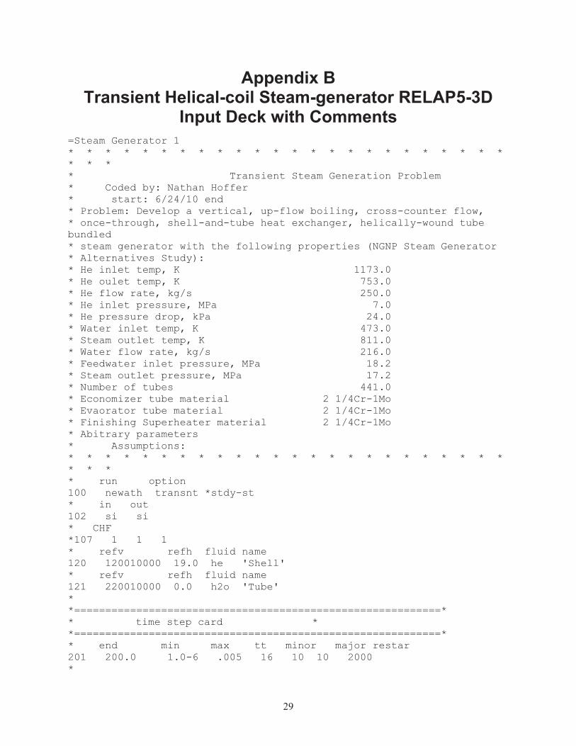
Appendix B Transient Helical-coil Steam Generator, RELAP5-3D Input Deck ....................................... 28�
Appendix C Beginner’s RELAP5-3D User Guide..................................................................................... 49�
x
FIGURES Figure 1. NGNP reference design. ................................................................................................................ 1�
Figure 2. Schematic of a prismatic reactor vessel. ........................................................................................ 2�
Figure 3. Schematic of the pebble-bed reactor vessel. .................................................................................. 3�
Figure 4. Cutaway of a helical-coil steam generator. .................................................................................... 4�
Figure 5. NGNP helical-coil steam-generator preconceptual design. ........................................................... 5�
Figure 6. Calculation sections with corresponding notation. ........................................................................ 7�
Figure 7. Helical-coil bundle simplifications. ............................................................................................. 13�
Figure 8. RELAP5-3D/ATHENA steam-generator model node visualization: primary system. ............... 15�
Figure 9. RELAP5-3D/ATHENA steam-generator model node visualization: secondary system. ............ 16�
Figure 10. Heat structure connections with hydrodynamic component. ..................................................... 17�
Figure 11. Exponential pressure decrease of primary inlet pressure. .......................................................... 19�
Figure 12. Secondary inlet/outlet pressure response. .................................................................................. 20�
Figure 13. Primary inlet/outlet temperature response. ................................................................................ 21�
Figure 14. Secondary inlet/outlet temperature response. ............................................................................ 21�
Figure 15. Primary inlet/outlet mass-flow rate response. ........................................................................... 22�
Figure 16. Secondary inlet/outlet mass-flow rate response. ....................................................................... 22�
TABLES
Table 1. Preconceptual NGNP helical-coil steam generator design parameters. .......................................... 6�
Table 2. Heat-load balance: secondary system initial conditions. ................................................................ 7�
Table 3. Heat-load balance: primary system initial conditions for mass-flow rate calculations. ................ 11�
Table 4. Conditions used in solving for the overall heat-transfer coefficient. ............................................ 11�
Table 5. Steady state results. ....................................................................................................................... 18�
Table 6. Primary inlet/outlet pressure inputs. ............................................................................................. 19�
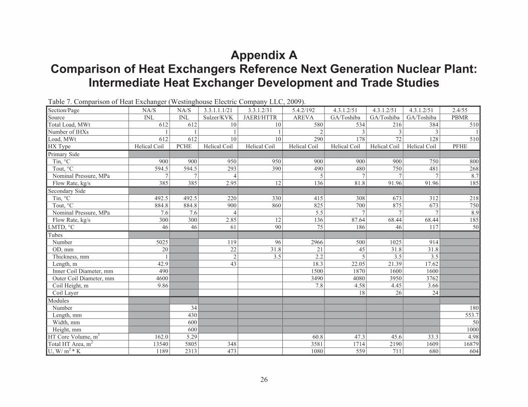
Table 7. Comparison of Heat Exchanger (Westinghouse Electric Company LLC, 2009). ........................ 26�
xi
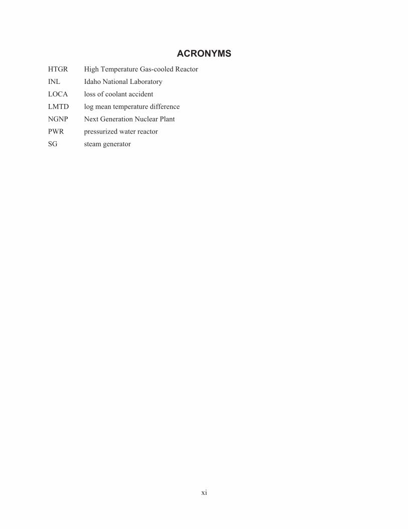
ACRONYMS HTGR High Temperature Gas-cooled Reactor
INL Idaho National Laboratory
LOCA loss of coolant accident
LMTD log mean temperature difference
NGNP Next Generation Nuclear Plant
PWR pressurized water reactor
SG steam generator
xii
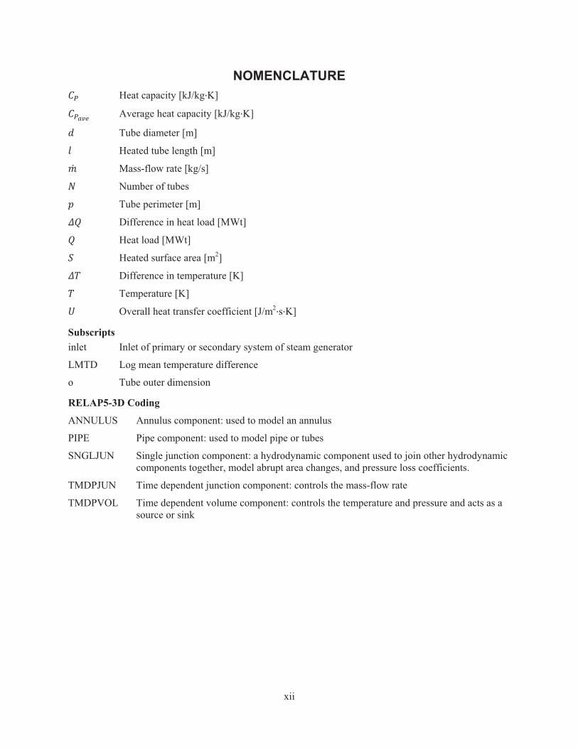
NOMENCLATURE �� Heat capacity [kJ/kg�K]
����� Average heat capacity [kJ/kg�K]
� Tube diameter [m]
� Heated tube length [m]
Mass-flow rate [kg/s]
� Number of tubes
� Tube perimeter [m]
� Difference in heat load [MWt]
� Heat load [MWt]
� Heated surface area [m2]
� Difference in temperature [K]
� Temperature [K]
� Overall heat transfer coefficient [J/m2�s�K]
Subscripts inlet Inlet of primary or secondary system of steam generator
LMTD Log mean temperature difference
o Tube outer dimension
RELAP5-3D Coding
ANNULUS Annulus component: used to model an annulus
PIPE Pipe component: used to model pipe or tubes
SNGLJUN Single junction component: a hydrodynamic component used to join other hydrodynamic components together, model abrupt area changes, and pressure loss coefficients.
TMDPJUN Time dependent junction component: controls the mass-flow rate
TMDPVOL Time dependent volume component: controls the temperature and pressure and acts as a source or sink
1
Modeling a Helical-coil Steam Generator in RELAP5-3D for the Next Generation Nuclear Plant
1. INTRODUCTION With the recent advances in nuclear technologies, the possibility of using nuclear plants for process
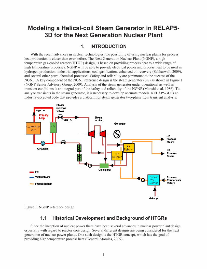
heat production is closer than ever before. The Next Generation Nuclear Plant (NGNP), a high temperature gas-cooled reactor (HTGR) design, is based on providing process heat to a wide range of high temperature processes. NGNP will be able to provide electrical power and process heat to be used in hydrogen production, industrial applications, coal gasification, enhanced oil recovery (Sabharwall, 2009), and several other petro-chemical processes. Safety and reliability are paramount to the success of the NGNP. A key component of the NGNP reference design is the steam generator (SG) as shown in Figure 1 (NGNP Senior Advisory Group, 2009). Analysis of the steam generator under operational as well as transient conditions is an integral part of the safety and reliability of the NGNP (Munshi et al. 1986). To analyze transients in the steam generator, it is necessary to develop accurate models. RELAP5-3D is an industry-accepted code that provides a platform for steam generator two-phase flow transient analysis.
Figure 1. NGNP reference design.
1.1 Historical Development and Background of HTGRs Since the inception of nuclear power there have been several advances in nuclear power plant design,
especially with regard to reactor core design. Several different designs are being considered for the next generation of nuclear power plants. One such design is the HTGR concept, which has the goal of providing high temperature process heat (General Atomics, 2009).
2
HTGRs use helium as the coolant because of its non-reactivity at high temperatures. The inert nature of helium is also beneficial to the reactor core structure as well as to the steam generator where other coolants corrode the structure at high temperatures (Melese and Katz, 1984). Also, as helium passes through the core, it does not become radioactive, which provides added safety in the event of a breach in the reactor.
1.1.1 HTGR Core Designs
There are two distinct core designs for HTGRs: prismatic and pebble bed.
1.1.1.1 Prismatic Core Design
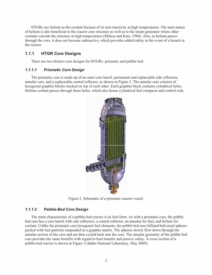
The prismatic core is made up of an outer core barrel, permanent and replaceable side reflectors, annular core, and a replaceable central reflector, as shown in Figure 2. The annular core consists of hexagonal graphite blocks stacked on top of each other. Each graphite block contains cylindrical holes. Helium coolant passes through these holes, which also house cylindrical fuel compacts and control rods.
Figure 2. Schematic of a prismatic reactor vessel.
1.1.1.2 Pebble-Bed Core Design
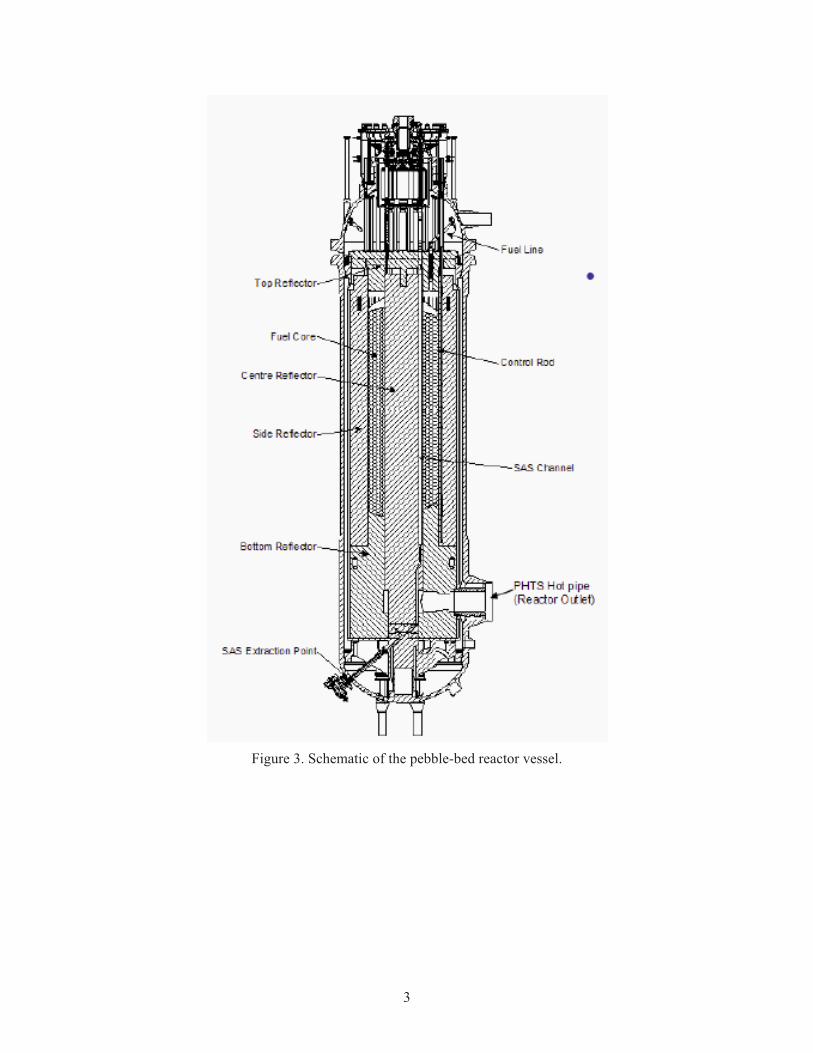
The main characteristic of a pebble-bed reactor is its fuel form. As with a prismatic core, the pebble bed core has a core barrel with side reflectors, a central reflector, an annulus for fuel, and helium for coolant. Unlike the prismatic core hexagonal fuel elements, the pebble bed uses billiard-ball-sized spheres packed with fuel particles suspended in a graphite matrix. The spheres slowly flow down through the annular section of the core and are then cycled back into the core. The annular geometry of the pebble bed core provides the same benefits with regard to heat transfer and passive safety. A cross section of a pebble-bed reactor is shown in Figure 3 (Idaho National Laboratory, May 2009).
3
Figure 3. Schematic of the pebble-bed reactor vessel.
4
1.2 Historical Development and Background of Steam Generators
A steam generator is a heat exchanger made up of a shell (primary side) and several small tubes (secondary side), on the order of centimeters in diameter, which are bundled together. There are several shell and tube configurations. To increase heat transfer, baffles can be used to force the shell side coolant to cross over the tubes. Baffle designs vary widely, but serve the same purpose to increase the effectiveness of the heat exchanger. Tubes can also make more than one pass through the shell to increase the heat exchanger effectiveness. The tubes can be modified to have fins that increase heat transfer area.
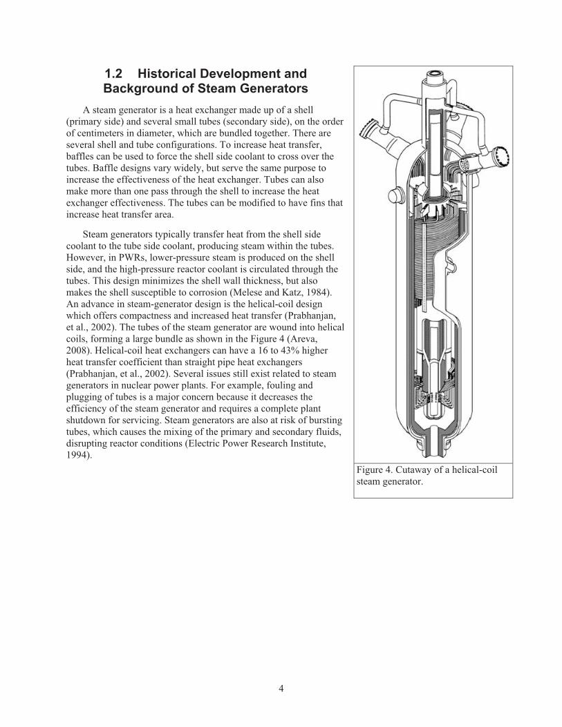
Steam generators typically transfer heat from the shell side coolant to the tube side coolant, producing steam within the tubes. However, in PWRs, lower-pressure steam is produced on the shell side, and the high-pressure reactor coolant is circulated through the tubes. This design minimizes the shell wall thickness, but also makes the shell susceptible to corrosion (Melese and Katz, 1984). An advance in steam-generator design is the helical-coil design which offers compactness and increased heat transfer (Prabhanjan, et al., 2002). The tubes of the steam generator are wound into helical coils, forming a large bundle as shown in the Figure 4 (Areva, 2008). Helical-coil heat exchangers can have a 16 to 43% higher heat transfer coefficient than straight pipe heat exchangers (Prabhanjan, et al., 2002). Several issues still exist related to steam generators in nuclear power plants. For example, fouling and plugging of tubes is a major concern because it decreases the efficiency of the steam generator and requires a complete plant shutdown for servicing. Steam generators are also at risk of bursting tubes, which causes the mixing of the primary and secondary fluids, disrupting reactor conditions (Electric Power Research Institute, 1994).
Figure 4. Cutaway of a helical-coil steam generator.
5
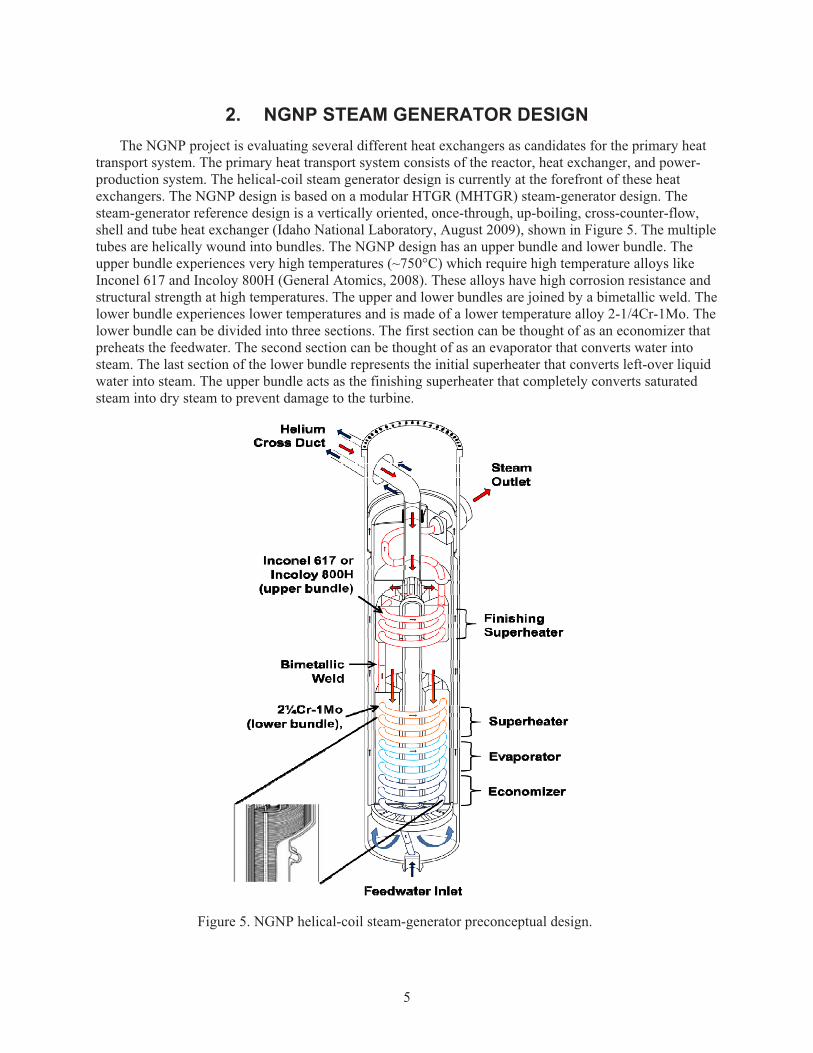
2. NGNP STEAM GENERATOR DESIGN The NGNP project is evaluating several different heat exchangers as candidates for the primary heat
transport system. The primary heat transport system consists of the reactor, heat exchanger, and power-production system. The helical-coil steam generator design is currently at the forefront of these heat exchangers. The NGNP design is based on a modular HTGR (MHTGR) steam-generator design. The steam-generator reference design is a vertically oriented, once-through, up-boiling, cross-counter-flow, shell and tube heat exchanger (Idaho National Laboratory, August 2009), shown in Figure 5. The multiple tubes are helically wound into bundles. The NGNP design has an upper bundle and lower bundle. The upper bundle experiences very high temperatures (~750°C) which require high temperature alloys like Inconel 617 and Incoloy 800H (General Atomics, 2008). These alloys have high corrosion resistance and structural strength at high temperatures. The upper and lower bundles are joined by a bimetallic weld. The lower bundle experiences lower temperatures and is made of a lower temperature alloy 2-1/4Cr-1Mo. The lower bundle can be divided into three sections. The first section can be thought of as an economizer that preheats the feedwater. The second section can be thought of as an evaporator that converts water into steam. The last section of the lower bundle represents the initial superheater that converts left-over liquid water into steam. The upper bundle acts as the finishing superheater that completely converts saturated steam into dry steam to prevent damage to the turbine.
Figure 5. NGNP helical-coil steam-generator preconceptual design.
6
Helium enters the steam generator through the cross duct and is directed down through a central pipe. The central pipe opens up into an inner plenum. The helium then flows down around the individual helical-coil tubes. At the base plenum, the helium is redirected up through the annulus between the outer and inner shrouds, combining into the upper plenum. The helium then exits out the cross duct back into the reactor.
On the shell side, liquid water enters through the feedwater inlet and passes through the economizer, evaporator, and superheater sections, producing steam. The steam continues to the finishing superheater, which converts all steam into dry steam, before entering the turbomachinery.
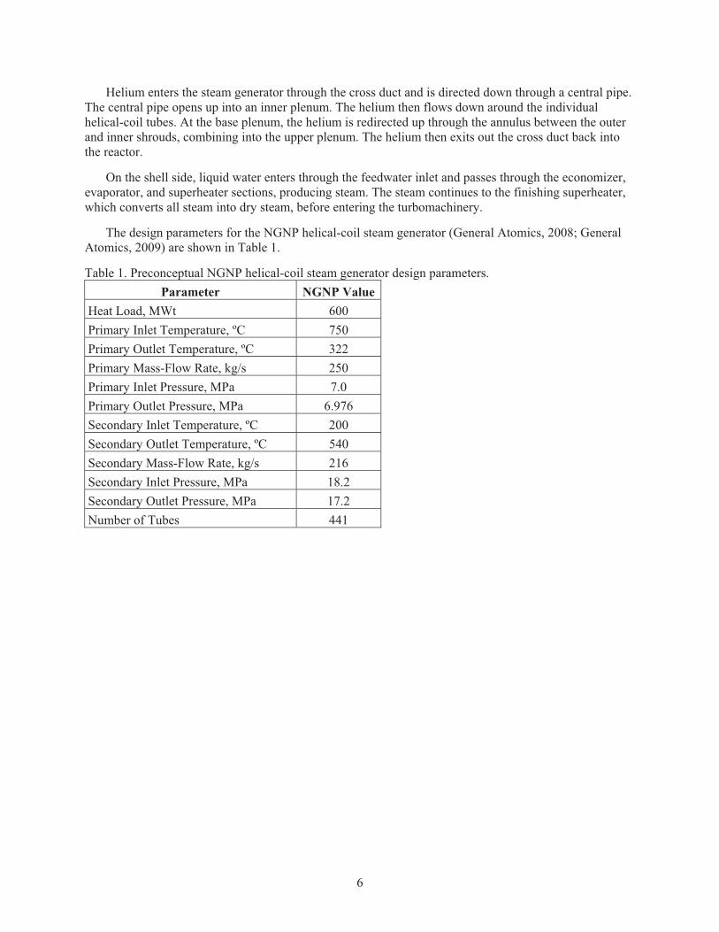
The design parameters for the NGNP helical-coil steam generator (General Atomics, 2008; General Atomics, 2009) are shown in Table 1.
Table 1. Preconceptual NGNP helical-coil steam generator design parameters. Parameter NGNP Value
Heat Load, MWt 600 Primary Inlet Temperature, ºC 750 Primary Outlet Temperature, ºC 322 Primary Mass-Flow Rate, kg/s 250 Primary Inlet Pressure, MPa 7.0 Primary Outlet Pressure, MPa 6.976 Secondary Inlet Temperature, ºC 200 Secondary Outlet Temperature, ºC 540 Secondary Mass-Flow Rate, kg/s 216 Secondary Inlet Pressure, MPa 18.2 Secondary Outlet Pressure, MPa 17.2 Number of Tubes 441
7
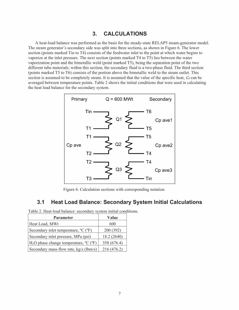
3. CALCULATIONS A heat-load balance was performed as the basis for the steady-state RELAP5 steam-generator model.
The steam generator’s secondary side was split into three sections, as shown in Figure 6. The lower section (points marked Tin to T4) consists of the feedwater inlet to the point at which water begins to vaporize at the inlet pressure. The next section (points marked T4 to T5) lies between the water vaporization point and the bimetallic weld (point marked T5), being the separation point of the two different tube materials; within this section, the secondary fluid is a two-phase fluid. The third section (points marked T5 to T6) consists of the portion above the bimetallic weld to the steam outlet. This section is assumed to be completely steam. It is assumed that the value of the specific heat, �� can be averaged between temperature points. Table 2 shows the initial conditions that were used in calculating the heat load balance for the secondary system.
Figure 6. Calculation sections with corresponding notation.
3.1 Heat Load Balance: Secondary System Initial Calculations Table 2. Heat-load balance: secondary system initial conditions.
Parameter Value Heat Load, MWt 600 Secondary inlet temperature, ºC (ºF) 200 (392) Secondary inlet pressure, MPa (psi) 18.2 (2640) H2O phase change temperature, ºC (ºF) 358 (676.4) Secondary mass-flow rate, kg/s (lbm/s) 216 (476.2)
8
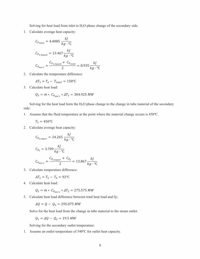
Solving for heat load from inlet to H2O phase change of the secondary side.
1. Calculate average heat capacity:
������� � ������� � �! " #
��$���%&�' � ()��*+ � �! " #�
������, ���$���%&�' -��������
. � ��/)� � �! " #
2. Calculate the temperature difference:
�0 � �1 2��34567 � (��#
3. Calculate heat load:
�0 � 8 �������, 8 �0 � )���/.��9:
Solving for the heat load form the H2O phase change to the change in tube material of the secondary side:
1. Assume that the fluid temperature at the point where the material change occurs is 450ºC.
�; � ���#
2. Calculate average heat capacity:
��$���<=> � .��.*�� � �! " #
��? � )�+�/ � �! " #�
������@ ���$���<=> -���?
. � ()��*+ � �! " #
3. Calculate temperature difference:
�A � �; 2��1 � /.#
4. Calculate heat load:
�A � 8 �������@ 8 �A � .+���+��9:
5. Calculate heat load difference between total heat load and Q3:
� � � 2��0 � ./���+��9:� Solve for the heat load from the change in tube material to the steam outlet.
�B � � 2��A � (/���9:� Solving for the secondary outlet temperature:
1. Assume an outlet temperature of 540ºC for outlet heat capacity.
9
2. Calculate average heat capacity:
��C � .�/���� � �! " #
��? � )�+�/ � �! " #�
������D � ��C -���?. � )�)�* �
�! " #
3. Calculate outlet temperature:
�E � �; - FDG 8�HI����D
� �++�)(#.
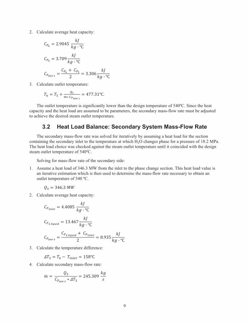
The outlet temperature is significantly lower than the design temperature of 540ºC. Since the heat capacity and the heat load are assumed to be parameters, the secondary mass-flow rate must be adjusted to achieve the desired steam outlet temperature.
3.2 Heat Load Balance: Secondary System Mass-Flow Rate The secondary mass-flow rate was solved for iteratively by assuming a heat load for the section
containing the secondary inlet to the temperature at which H2O changes phase for a pressure of 18.2 MPa. The heat load choice was checked against the steam outlet temperature until it coincided with the design steam outlet temperature of 540ºC.
Solving for mass-flow rate of the secondary side:
1. Assume a heat load of 346.3 MW from the inlet to the phase change section. This heat load value is an iterative estimation which is then used to determine the mass-flow rate necessary to obtain an outlet temperature of 540 ºC.
�0 � )�*�)�9:
2. Calculate average heat capacity:
������� � ������� � �! " #
��$���%&�' � ()��*+ � �! " #�
������, ���$���%&�' -��������
. � ��/)� � �! " #
3. Calculate the temperature difference:
�0 � �1 2��34567 � (��#
4. Calculate secondary mass-flow rate:
� � �0������, 8 �0
� .���)�/� �!J
10
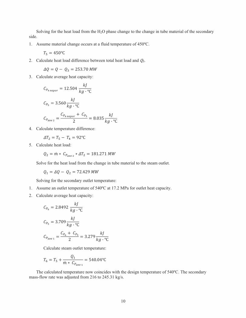
Solving for the heat load from the H2O phase change to the change in tube material of the secondary side.
1. Assume material change occurs at a fluid temperature of 450ºC.
�; � ���#
2. Calculate heat load difference between total heat load and K).
� � � 2��0 � .�)�+��9:� 3. Calculate average heat capacity:
��$���<=> � (.����� � �! " #
��? � )��*� � �! " #�
������@ ���$���<=> -���?
. � ���)� � �! " #
4. Calculate temperature difference:
�A � �; 2��1 � /.#
5. Calculate heat load:
�A � 8 �������@ 8 �A � (�(�.+(�9:
Solve for the heat load from the change in tube material to the steam outlet.
�B � � 2��A � +.��./�9:� Solving for the secondary outlet temperature:
1. Assume an outlet temperature of 540ºC at 17.2 MPa for outlet heat capacity.
2. Calculate average heat capacity:
��C � .���/.� � �! " #
��? � )�+�/ � �! " #�
������D � ��C -���?. � )�.+/ �
�! " #
Calculate steam outlet temperature:
�E � �; - �B 8 �������D
� ������#
The calculated temperature now coincides with the design temperature of 540ºC. The secondary mass-flow rate was adjusted from 216 to 245.31 kg/s.
11
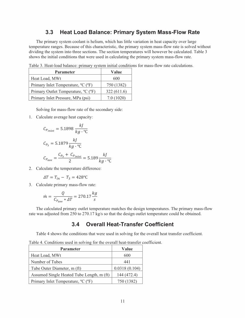
3.3 Heat Load Balance: Primary System Mass-Flow Rate The primary system coolant is helium, which has little variation in heat capacity over large
temperature ranges. Because of this characteristic, the primary system mass-flow rate is solved without dividing the system into three sections. The section temperatures will however be calculated. Table 3 shows the initial conditions that were used in calculating the primary system mass-flow rate.
Table 3. Heat-load balance: primary system initial conditions for mass-flow rate calculations. Parameter Value
Heat Load, MWt 600 Primary Inlet Temperature, ºC (ºF) 750 (1382) Primary Outlet Temperature, ºC (ºF) 322 (611.6) Primary Inlet Pressure, MPa (psi) 7.0 (1020)
Solving for mass-flow rate of the secondary side:
1. Calculate average heat capacity:
������� � ��(�/�� � �! " #
��, � ��(�+/ � �! " #�
����� � ��, -��������. � ��(�/ �
�! " #
2. Calculate the temperature difference:
� � �34 2��0 � �.�#
3. Calculate primary mass-flow rate:
� � ������ 8 � � .+��(+ �!
J
The calculated primary outlet temperature matches the design temperatures. The primary mass-flow rate was adjusted from 250 to 270.17 kg/s so that the design outlet temperature could be obtained.
3.4 Overall Heat-Transfer Coefficient Table 4 shows the conditions that were used in solving for the overall heat transfer coefficient.
Table 4. Conditions used in solving for the overall heat-transfer coefficient. Parameter Value
Heat Load, MWt 600 Number of Tubes 441 Tube Outer Diameter, m (ft) 0.0318 (0.104)Assumed Single Heated Tube Length, m (ft) 144 (472.4) Primary Inlet Temperature, ºC (ºF) 750 (1382)
12
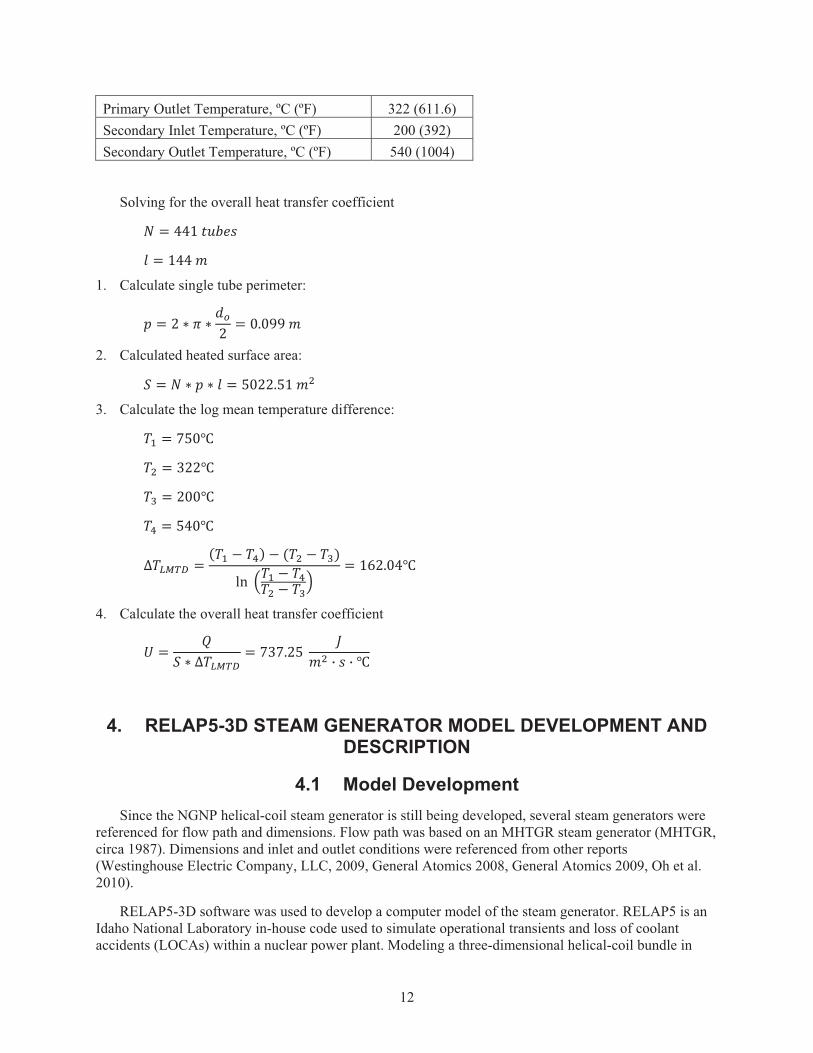
Primary Outlet Temperature, ºC (ºF) 322 (611.6) Secondary Inlet Temperature, ºC (ºF) 200 (392) Secondary Outlet Temperature, ºC (ºF) 540 (1004)
Solving for the overall heat transfer coefficient
� � ��(�LMNOJ
� � (���
1. Calculate single tube perimeter:
� � . 8 P 8 �Q. � ���//�
2. Calculated heated surface area:
� � � 8 � 8 � � ��..��(�A
3. Calculate the log mean temperature difference:
�B � +��#
�A � )..#
�0 � .��#
�1 � ���#
R�STUV � W�B 2 �1X 2 W�A 2 �0XYZ� [�B 2 �1
�A 2 �0\
� (*.���#
4. Calculate the overall heat transfer coefficient
� � �� 8 R�STUV
� +)+�.�� A " J " #
4. RELAP5-3D STEAM GENERATOR MODEL DEVELOPMENT AND DESCRIPTION
4.1 Model Development Since the NGNP helical-coil steam generator is still being developed, several steam generators were
referenced for flow path and dimensions. Flow path was based on an MHTGR steam generator (MHTGR, circa 1987). Dimensions and inlet and outlet conditions were referenced from other reports (Westinghouse Electric Company, LLC, 2009, General Atomics 2008, General Atomics 2009, Oh et al. 2010).
RELAP5-3D software was used to develop a computer model of the steam generator. RELAP5 is an Idaho National Laboratory in-house code used to simulate operational transients and loss of coolant accidents (LOCAs) within a nuclear power plant. Modeling a three-dimensional helical-coil bundle in
13
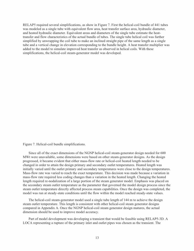
RELAP5 required several simplifications, as show in Figure 7. First the helical-coil bundle of 441 tubes was modeled as a single tube with equivalent flow area, heat transfer surface area, hydraulic diameter, and heated hydraulic diameter. Equivalent areas and diameters of the single tube estimate the heat-transfer and flow characteristics of the actual bundle of tubes. The single tube helical coil was further simplified by unwrapping the coil tube to make an inclined straight pipe of the same length as a single tube and a vertical change in elevation corresponding to the bundle height. A heat transfer multiplier was added to the model to simulate improved heat transfer as observed in helical coils. With these simplifications, the helical-coil steam-generator model was developed.
Figure 7. Helical-coil bundle simplifications.
Since all of the exact dimensions of the NGNP helical-coil steam-generator design needed for 600 MWt were unavailable, some dimensions were based on other steam-generator designs. As the design progressed, it became evident that either mass-flow rate or helical-coil heated length needed to be changed in order to attain the design primary and secondary outlet temperatures. Heated length was initially varied until the outlet primary and secondary temperatures were close to the design temperatures. Mass-flow rate was varied to reach the exact temperature. This decision was made because a variation in mass-flow rate required less coding changes than a variation in the heated length. Changing the heated length required re-nodalization of a large portion of the steam generator model. Emphasis was placed on the secondary steam outlet temperature as the parameter that governed the model design process since the steam outlet temperature directly affected process steam capabilities. Once the design was completed, the model was run at steady-state conditions until the flow within the model reached steady-state values.
The helical-coil steam-generator model used a single tube length of 144 m to achieve the design steam outlet temperature. This length is consistent with other helical-coil steam generator designs compared in Appendix A. Once the NGNP helical-coil steam generator design matures, the actual dimension should be used to improve model accuracy.
Part of model development was developing a transient that would be feasible using RELAP5-3D. A LOCA representing a rupture of the primary inlet and outlet pipes was chosen as the transient. The
14
rupture was simulated by an exponential decrease in the primary inlet and outlet pressures. Other steam generator transient studies have also simulated LOCAs using ramp inputs for pressure (Munshi et al. 1985, Bhathagar et al. 1985, Munshi et al. 1986). Feedback from the reactor and power-conversion system were not considered in this model.
4.2 Model Description The primary and secondary systems of the steam generator model are divided into several nodes.
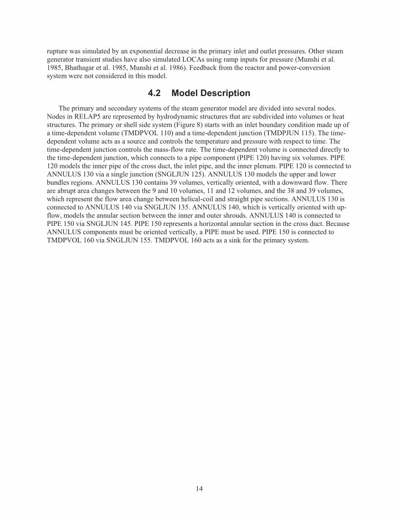
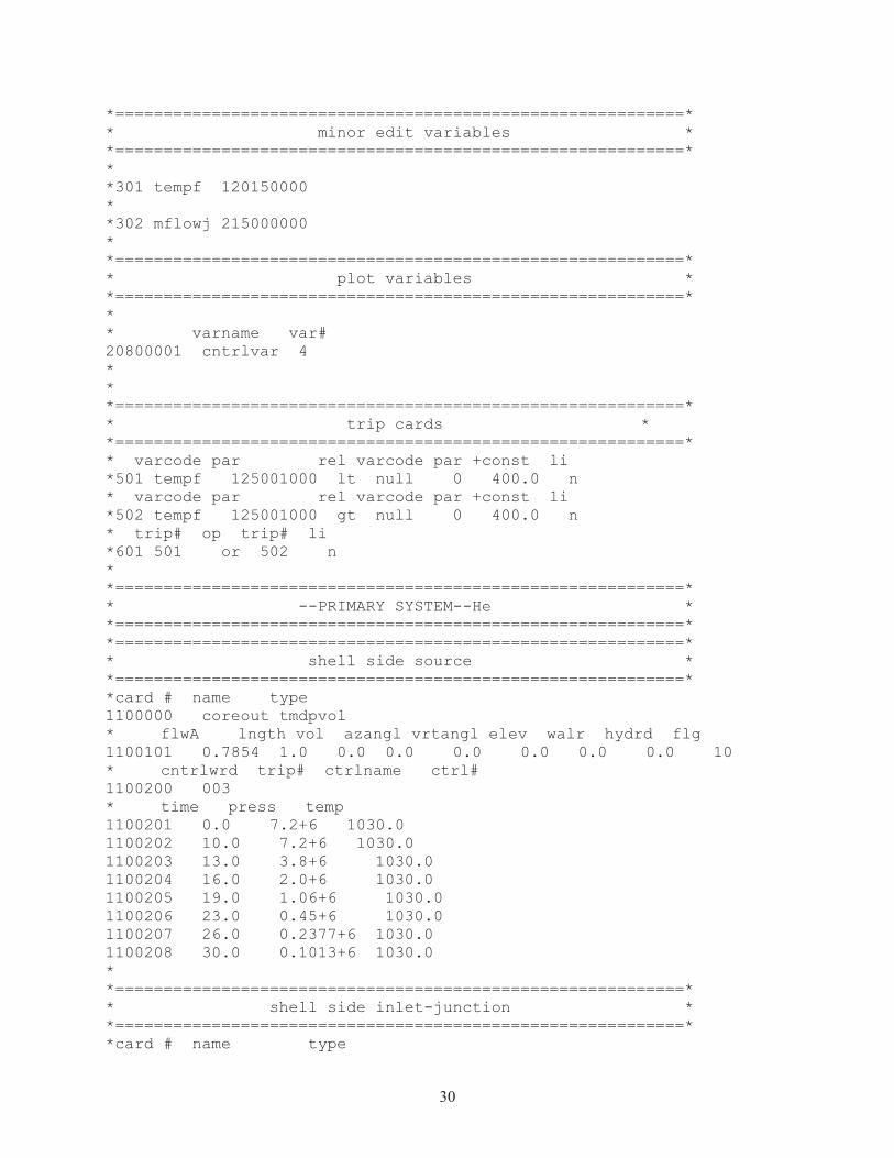
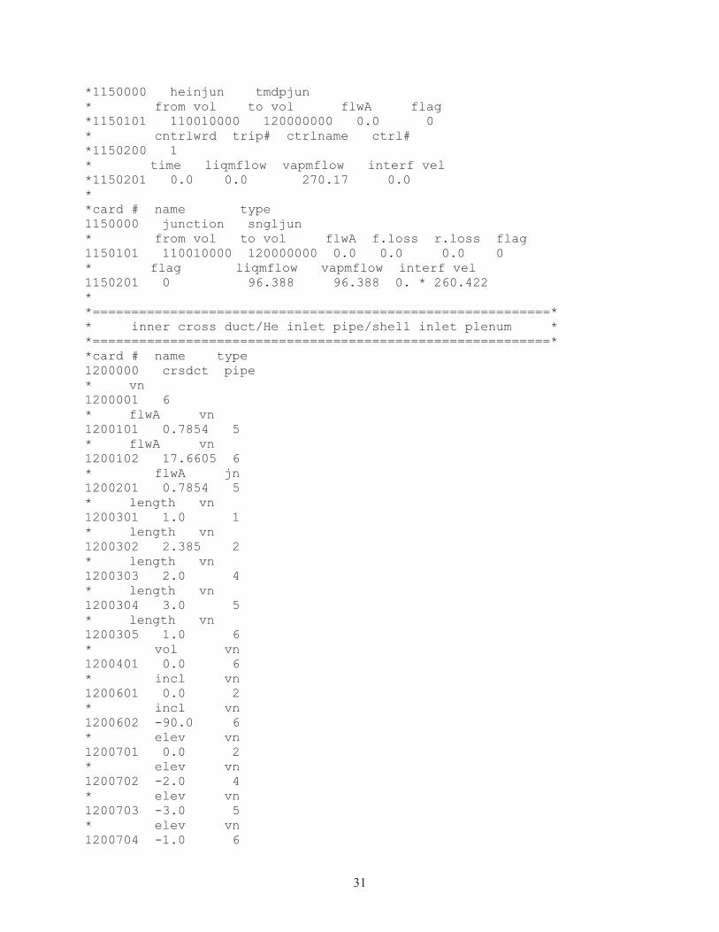
Nodes in RELAP5 are represented by hydrodynamic structures that are subdivided into volumes or heat structures. The primary or shell side system (Figure 8) starts with an inlet boundary condition made up of a time-dependent volume (TMDPVOL 110) and a time-dependent junction (TMDPJUN 115). The time-dependent volume acts as a source and controls the temperature and pressure with respect to time. The time-dependent junction controls the mass-flow rate. The time-dependent volume is connected directly to the time-dependent junction, which connects to a pipe component (PIPE 120) having six volumes. PIPE 120 models the inner pipe of the cross duct, the inlet pipe, and the inner plenum. PIPE 120 is connected to ANNULUS 130 via a single junction (SNGLJUN 125). ANNULUS 130 models the upper and lower bundles regions. ANNULUS 130 contains 39 volumes, vertically oriented, with a downward flow. There are abrupt area changes between the 9 and 10 volumes, 11 and 12 volumes, and the 38 and 39 volumes, which represent the flow area change between helical-coil and straight pipe sections. ANNULUS 130 is connected to ANNULUS 140 via SNGLJUN 135. ANNULUS 140, which is vertically oriented with up-flow, models the annular section between the inner and outer shrouds. ANNULUS 140 is connected to PIPE 150 via SNGLJUN 145. PIPE 150 represents a horizontal annular section in the cross duct. Because ANNULUS components must be oriented vertically, a PIPE must be used. PIPE 150 is connected to TMDPVOL 160 via SNGLJUN 155. TMDPVOL 160 acts as a sink for the primary system.
15
Figure 8. RELAP5-3D/ATHENA steam-generator model node visualization: primary system.
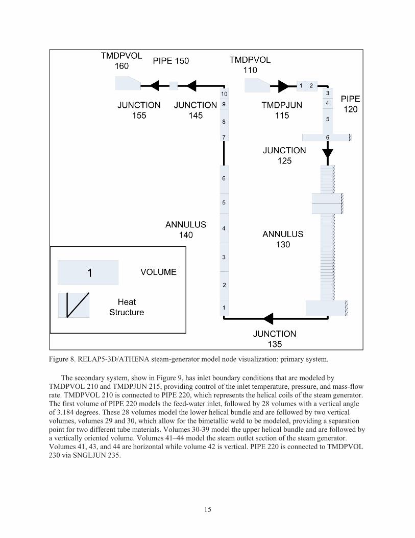
The secondary system, show in Figure 9, has inlet boundary conditions that are modeled by TMDPVOL 210 and TMDPJUN 215, providing control of the inlet temperature, pressure, and mass-flow rate. TMDPVOL 210 is connected to PIPE 220, which represents the helical coils of the steam generator. The first volume of PIPE 220 models the feed-water inlet, followed by 28 volumes with a vertical angle of 3.184 degrees. These 28 volumes model the lower helical bundle and are followed by two vertical volumes, volumes 29 and 30, which allow for the bimetallic weld to be modeled, providing a separation point for two different tube materials. Volumes 30-39 model the upper helical bundle and are followed by a vertically oriented volume. Volumes 41–44 model the steam outlet section of the steam generator. Volumes 41, 43, and 44 are horizontal while volume 42 is vertical. PIPE 220 is connected to TMDPVOL 230 via SNGLJUN 235.
16
Figure 9. RELAP5-3D/ATHENA steam-generator model node visualization: secondary system.
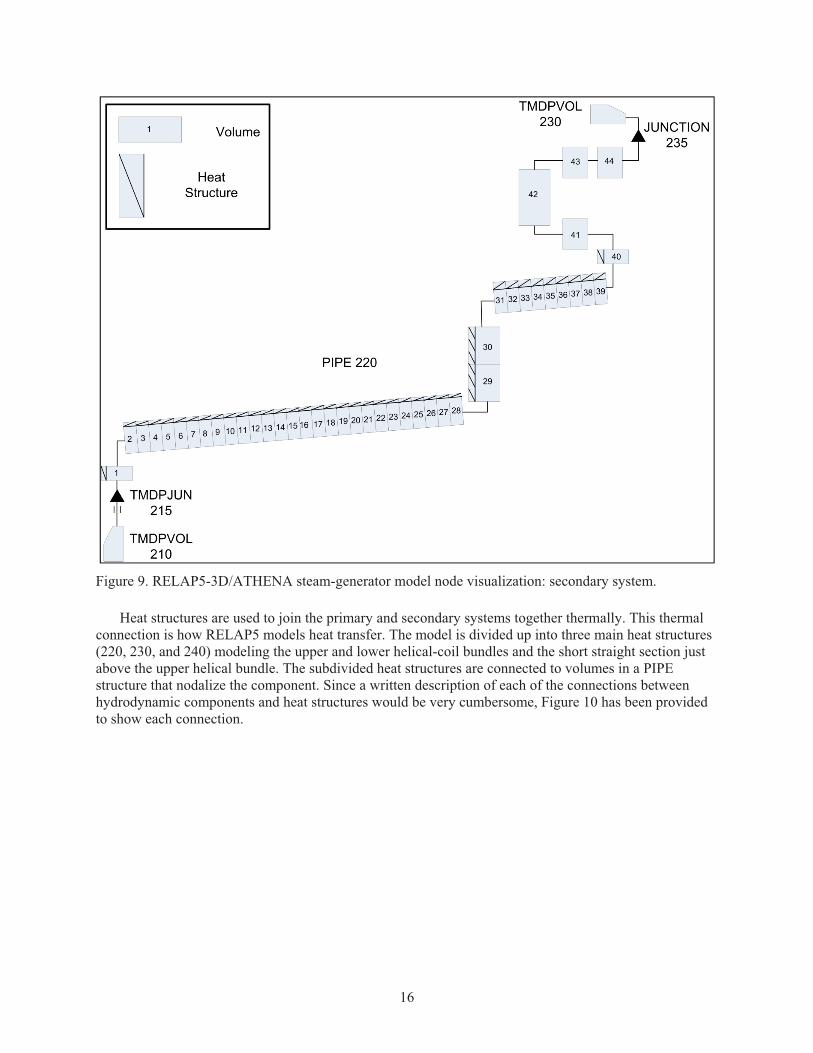
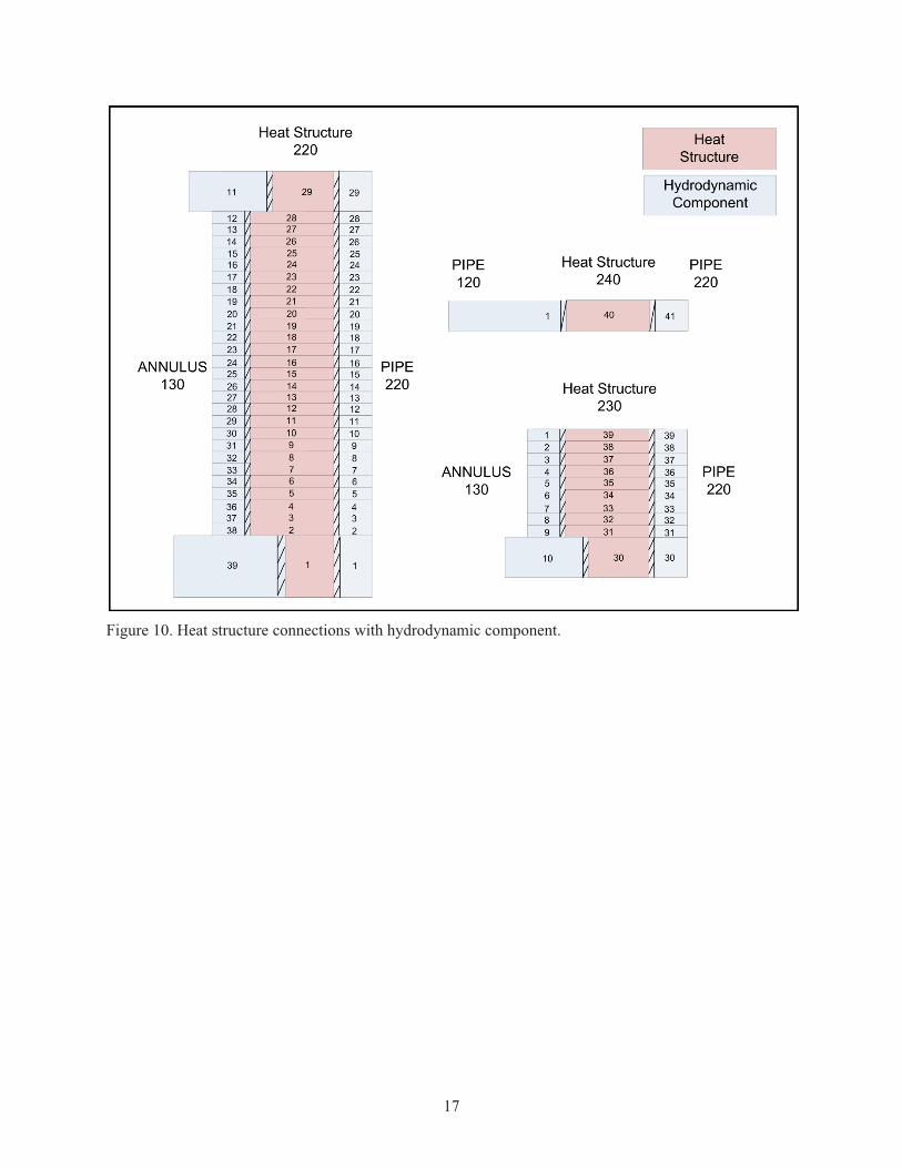
Heat structures are used to join the primary and secondary systems together thermally. This thermal connection is how RELAP5 models heat transfer. The model is divided up into three main heat structures (220, 230, and 240) modeling the upper and lower helical-coil bundles and the short straight section just above the upper helical bundle. The subdivided heat structures are connected to volumes in a PIPE structure that nodalize the component. Since a written description of each of the connections between hydrodynamic components and heat structures would be very cumbersome, Figure 10 has been provided to show each connection.
17
Figure 10. Heat structure connections with hydrodynamic component.
18
5. RESULTS
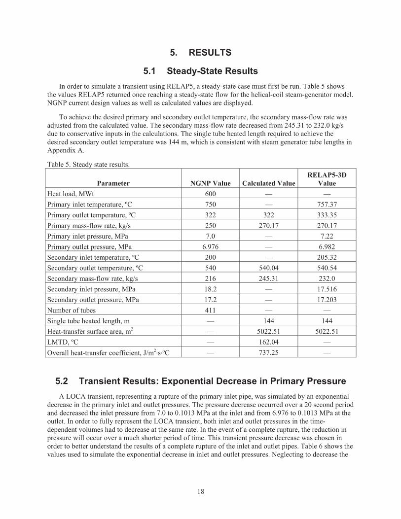
5.1 Steady-State Results In order to simulate a transient using RELAP5, a steady-state case must first be run. Table 5 shows
the values RELAP5 returned once reaching a steady-state flow for the helical-coil steam-generator model. NGNP current design values as well as calculated values are displayed.
To achieve the desired primary and secondary outlet temperature, the secondary mass-flow rate was adjusted from the calculated value. The secondary mass-flow rate decreased from 245.31 to 232.0 kg/s due to conservative inputs in the calculations. The single tube heated length required to achieve the desired secondary outlet temperature was 144 m, which is consistent with steam generator tube lengths in Appendix A.
Table 5. Steady state results.
Parameter NGNP Value Calculated Value RELAP5-3D
Value Heat load, MWt 600 — — Primary inlet temperature, ºC 750 — 757.37 Primary outlet temperature, ºC 322 322 333.35 Primary mass-flow rate, kg/s 250 270.17 270.17 Primary inlet pressure, MPa 7.0 — 7.22 Primary outlet pressure, MPa 6.976 — 6.982 Secondary inlet temperature, ºC 200 — 205.32 Secondary outlet temperature, ºC 540 540.04 540.54 Secondary mass-flow rate, kg/s 216 245.31 232.0 Secondary inlet pressure, MPa 18.2 — 17.516 Secondary outlet pressure, MPa 17.2 — 17.203 Number of tubes 411 — — Single tube heated length, m — 144 144 Heat-transfer surface area, m2 — 5022.51 5022.51 LMTD, ºC — 162.04 — Overall heat-transfer coefficient, J/m2�s�ºC — 737.25 —
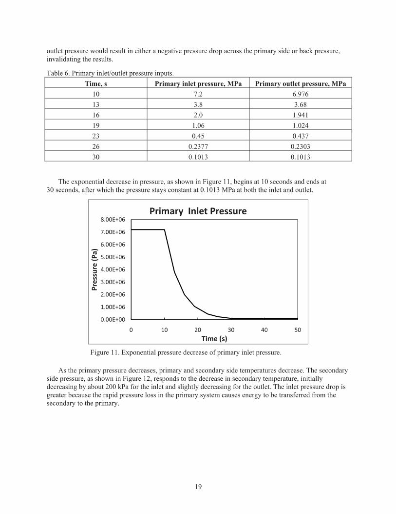
5.2 Transient Results: Exponential Decrease in Primary Pressure A LOCA transient, representing a rupture of the primary inlet pipe, was simulated by an exponential
decrease in the primary inlet and outlet pressures. The pressure decrease occurred over a 20 second period and decreased the inlet pressure from 7.0 to 0.1013 MPa at the inlet and from 6.976 to 0.1013 MPa at the outlet. In order to fully represent the LOCA transient, both inlet and outlet pressures in the time-dependent volumes had to decrease at the same rate. In the event of a complete rupture, the reduction in pressure will occur over a much shorter period of time. This transient pressure decrease was chosen in order to better understand the results of a complete rupture of the inlet and outlet pipes. Table 6 shows the values used to simulate the exponential decrease in inlet and outlet pressures. Neglecting to decrease the
19
outlet pressure would result in either a negative pressure drop across the primary side or back pressure, invalidating the results.
Table 6. Primary inlet/outlet pressure inputs. Time, s Primary inlet pressure, MPa Primary outlet pressure, MPa
10 7.2 6.976 13 3.8 3.68 16 2.0 1.941 19 1.06 1.024 23 0.45 0.437 26 0.2377 0.2303 30 0.1013 0.1013
The exponential decrease in pressure, as shown in Figure 11, begins at 10 seconds and ends at 30 seconds, after which the pressure stays constant at 0.1013 MPa at both the inlet and outlet.
Figure 11. Exponential pressure decrease of primary inlet pressure.
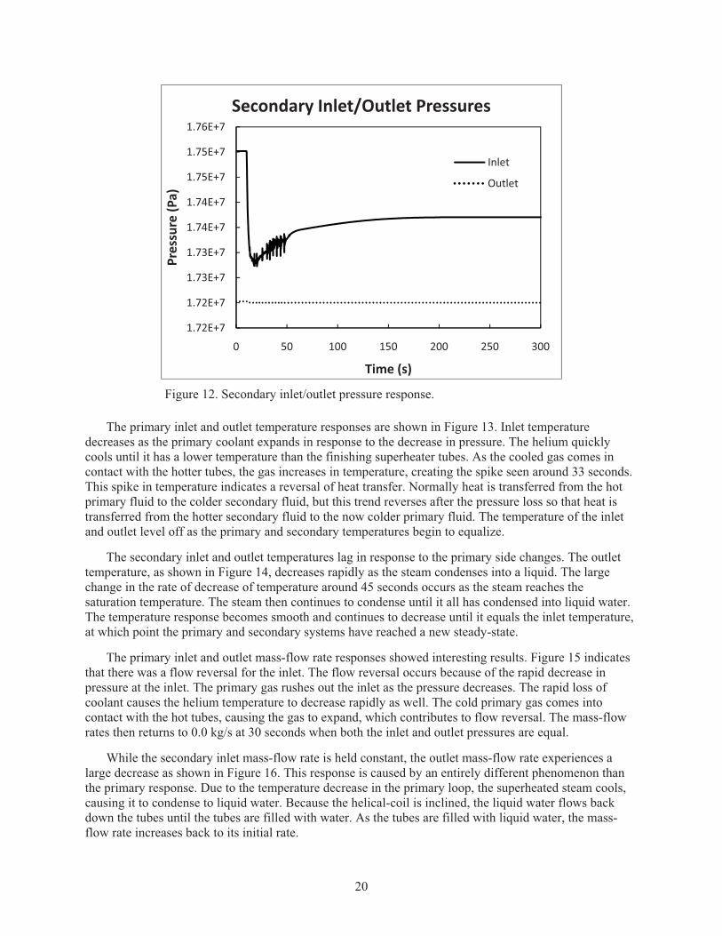
As the primary pressure decreases, primary and secondary side temperatures decrease. The secondary side pressure, as shown in Figure 12, responds to the decrease in secondary temperature, initially decreasing by about 200 kPa for the inlet and slightly decreasing for the outlet. The inlet pressure drop is greater because the rapid pressure loss in the primary system causes energy to be transferred from the secondary to the primary.
0.00E+00
1.00E+06
2.00E+06
3.00E+06
4.00E+06
5.00E+06
6.00E+06
7.00E+06
8.00E+06
0 10 20 30 40 50
Pressure�(P
a)
Time�(s)
Primary��Inlet�Pressure
20
Figure 12. Secondary inlet/outlet pressure response.
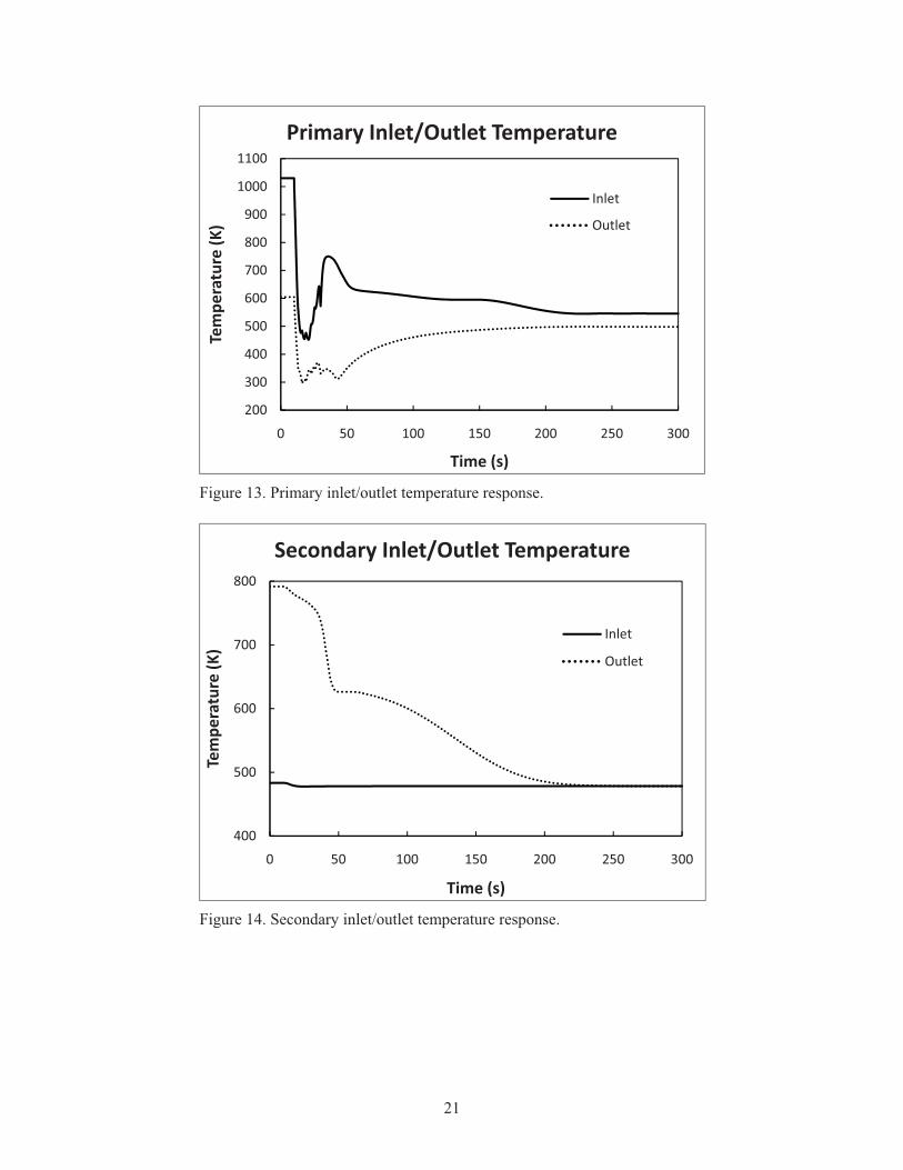
The primary inlet and outlet temperature responses are shown in Figure 13. Inlet temperature decreases as the primary coolant expands in response to the decrease in pressure. The helium quickly cools until it has a lower temperature than the finishing superheater tubes. As the cooled gas comes in contact with the hotter tubes, the gas increases in temperature, creating the spike seen around 33 seconds. This spike in temperature indicates a reversal of heat transfer. Normally heat is transferred from the hot primary fluid to the colder secondary fluid, but this trend reverses after the pressure loss so that heat is transferred from the hotter secondary fluid to the now colder primary fluid. The temperature of the inlet and outlet level off as the primary and secondary temperatures begin to equalize.
The secondary inlet and outlet temperatures lag in response to the primary side changes. The outlet temperature, as shown in Figure 14, decreases rapidly as the steam condenses into a liquid. The large change in the rate of decrease of temperature around 45 seconds occurs as the steam reaches the saturation temperature. The steam then continues to condense until it all has condensed into liquid water. The temperature response becomes smooth and continues to decrease until it equals the inlet temperature, at which point the primary and secondary systems have reached a new steady-state.
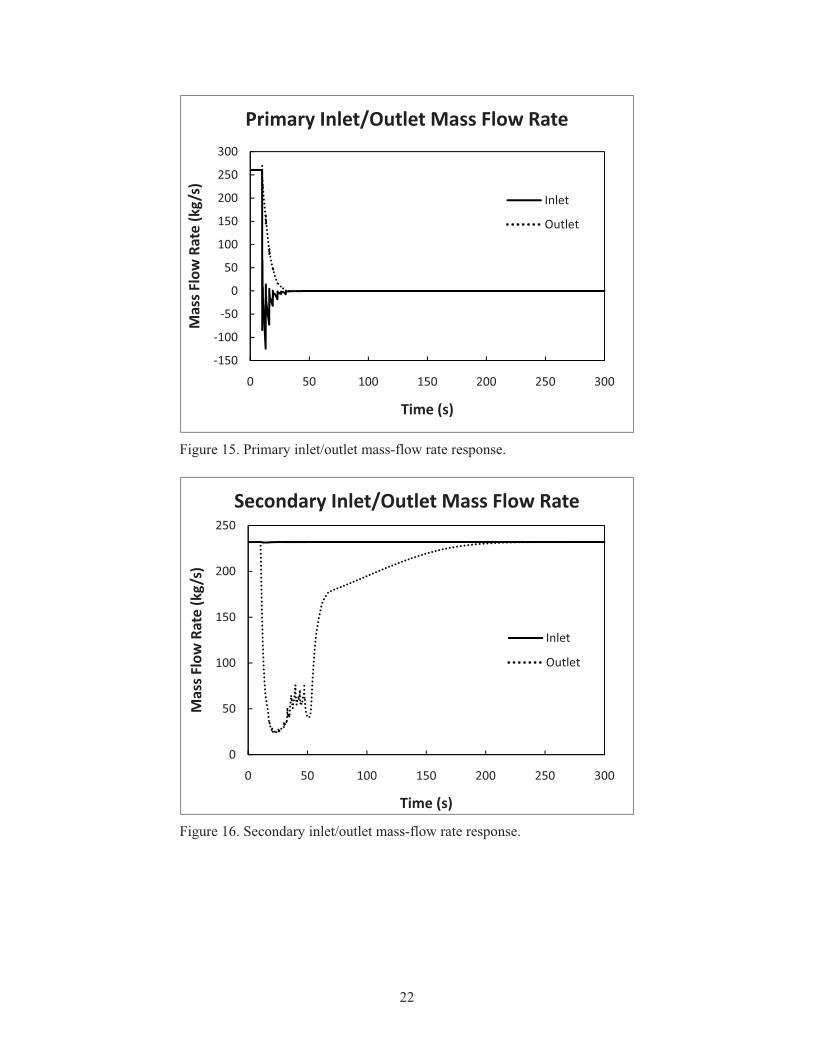
The primary inlet and outlet mass-flow rate responses showed interesting results. Figure 15 indicates that there was a flow reversal for the inlet. The flow reversal occurs because of the rapid decrease in pressure at the inlet. The primary gas rushes out the inlet as the pressure decreases. The rapid loss of coolant causes the helium temperature to decrease rapidly as well. The cold primary gas comes into contact with the hot tubes, causing the gas to expand, which contributes to flow reversal. The mass-flow rates then returns to 0.0 kg/s at 30 seconds when both the inlet and outlet pressures are equal.
While the secondary inlet mass-flow rate is held constant, the outlet mass-flow rate experiences a large decrease as shown in Figure 16. This response is caused by an entirely different phenomenon than the primary response. Due to the temperature decrease in the primary loop, the superheated steam cools, causing it to condense to liquid water. Because the helical-coil is inclined, the liquid water flows back down the tubes until the tubes are filled with water. As the tubes are filled with liquid water, the mass-flow rate increases back to its initial rate.
1.72E+7
1.72E+7
1.73E+7
1.73E+7
1.74E+7
1.74E+7
1.75E+7
1.75E+7
1.76E+7
0 50 100 150 200 250 300
Pressure�(P
a)
Time�(s)
Secondary�Inlet/Outlet�Pressures
Inlet
Outlet
21
Figure 13. Primary inlet/outlet temperature response.
Figure 14. Secondary inlet/outlet temperature response.
200
300
400
500
600
700
800
900
1000
1100
0 50 100 150 200 250 300
Tempe
rature�(K
)
Time�(s)
Primary�Inlet/Outlet�Temperature
Inlet
Outlet
400
500
600
700
800
0 50 100 150 200 250 300
Tempe
rature�(K
)
Time�(s)
Secondary�Inlet/Outlet�Temperature
Inlet
Outlet
22
Figure 15. Primary inlet/outlet mass-flow rate response.
Figure 16. Secondary inlet/outlet mass-flow rate response.
�150
�100
�50
0
50
100
150
200
250
300
0 50 100 150 200 250 300
Mass�Flow
�Rate�(kg/s)
Time�(s)
Primary�Inlet/Outlet�Mass�Flow�Rate
Inlet
Outlet
0
50
100
150
200
250
0 50 100 150 200 250 300
Mass�Flow
�Rate�(kg/s)
Time�(s)
Secondary�Inlet/Outlet�Mass�Flow�Rate
Inlet
Outlet
23
6. CONCLUSIONS AND FUTURE WORK
6.1 Conclusions A loss of primary pressure transient was simulated as an exponential decrease of primary pressure
using the RELAP5-3D helical-coil steam-generator model. Heat transfer between the primary and secondary systems experienced a reversal. The heat was initially transferred from the primary system to the secondary system. After the pressure loss, the heat was transferred from the secondary system to the primary system. The primary inlet mass-flow rate experiences a flow reversal. The steady-state model that was developed solved for the design steam outlet temperature using a lower mass-flow rate than was calculated because of conservative inputs.
6.2 Future Work In order to fully simulate operational and LOCA transients within the helical-coil steam-generator
model, the model must be coupled with a reactor core model. Future work includes the development of a working reactor model. Coupling the reactor and steam-generator models would allow for a feedback loop between the reactor and steam generator, realistically changing the steam-generator inlet conditions. Work will also be done on other transients including, but not limited to, start-up and shutdown operations and plugged and fouled tubes.
24
7. REFERENCES 1. General Atomics, Nuclear Heat Supply System Point Design Study for NGNP Conceptual Design,
911167, 2009.
2. General Atomics, NGNP Steam Generator Alternatives Study, 911120, 2008.
3. Westinghouse Electric Company LLC, Next Generation Nuclear Plant: Intermediate Heat Exchanger Development and Trade Studies, NGNP-NHS-HTS-RPT-M-00004, 2009.
4. RELAP5 Code Development Team, RELAP5 Vol. 1-5, INEEL-EXT-98-00834, Rev 2.4, 2005.
5. Chang H. Oh, Eung S. Kim, and Mike Patterson, "Design Option of Heat Exchanger for the Next Generation Nuclear Plant," Journal of Engineering for Gas Turbines and Power, Vol. 132, No. 3, 2010.
6. AREVA, NGNP with Hydrogen Production IHX and Secondary Heat Transport Loop Alternatives, 12-9076325-001, 2008.
7. Idaho National Laboratory, Next Generation Nuclear Plant Project, 2009 Status Report, INL/EXT-09-17505, May 2009.
8. Idaho National Laboratory, Next Generation Nuclear Plant Project Technology Development Roadmaps: The Technical Path Forward for 750-800ºC Reactor Outlet Temperature, INL/EXT-09-16598, August 2009.
9. Piyush Sabharwall, Engineering Design Elements of a Two-Phase Thermosyphon to Transfer NGNP Thermal Energy to a Hydrogen Plant, INL-EXT-09-15383, 2009.
10. NGNP Senior Advisory Group, “Senior Advisory Group Meeting Reference Configuration,” Meeting Minutes, January 28, 2009.
11. P. Munshi, R. Bhatnagar, and K.S. Ram, “Steam Generator Transient Studies Using a Simplified Two-Fluid Computer Code” Ann. Nucl. Energy, Vol. 12, No. 3, 1985, pp. 155–157.
12. P. Munshi, K. S. Ram, M. S. Kalra and D. V. Rao, “Steam-Generator Simulation With Non-Equilibrium Two-Phase Flow Models,” Ann. Nucl. Energy, Vol. 13, No. 11, 1986, pp. 617–621.
13. R. Bhatnagar, P. Munshi, and K. S. Ram, “A Simplified Two-Fluid Model of a Steam Generator for Digital Simulation of Operation Transients,” Ann. Nucl. Energy, Vol. 12, No. 7, 1985, pp. 349–355.
14. P.E MacDonald, P. D. Bayless, H. D. Gougar, R. L. Moore, A. M. Ougouag, R. L. Sant, J. W. Sterbentz, and W. K. Terry, “ The Next Generation Nuclear Plant – Insights Gained from the INEEL Point Design Studies,” INEEL/CON-04-01563 PREPRINT, 2004.
15. Gilbert Melese and Robert Katz, “Thermal and Flow Design of Helium-Cooled Reactors,” American Nuclear Society, 1984.
16. Electric Power Research Institute, “Steam Generator Reference Book Volume I,” Electric Power Research Institute, Inc, 1994, EPRI TR-103824s-V1R1.
17. Idaho National Laboratory, Pre-conceptual Design Report, INL/EXT-07-12937, 2007.
18. D.G. Prabhanjan, G.S.V. Ragbavan, and T.J. Rennie, “Comparison of Heat Transfer Rates Between a Straight Tube Heat Exchanger and a Helically Coiled Heat Exchanger,” International Communications in Heat and Mass Transfer, Vol. 29 No. 2, 2002, pp. 185–191

25
Appendix A
Comparison of Heat Exchangers Reference Next Generation Nuclear Plant: Intermediate Heat Exchanger Development and Trade Studies
26
Appendix A Comparison of Heat Exchangers Reference Next Generation Nuclear Plant:
Intermediate Heat Exchanger Development and Trade Studies Table 7. Comparison of Heat Exchanger (Westinghouse Electric Company LLC, 2009). Section/Page NA/S NA/S 3.3.1.1.1/21 3.3.1.2/31 5.4.2/192 4.3.1.2/51 4.3.1.2/51 4.3.1.2/51 2.4/55 Source INL INL Sulzer/KVK JAERI/HTTR AREVA GA/Toshiba GA/Toshiba GA/Toshiba PBMR Total Load, MWt 612 612 10 10 580 534 216 384 510Number of IHXs 1 1 1 1 2 3 3 3 1Load, MWt 612 612 10 10 290 178 72 128 510HX Type Helical Coil PCHE Helical Coil Helical Coil Helical Coil Helical Coil Helical Coil Helical Coil PFHE Primary Side Tin, °C 900 900 950 950 900 900 900 750 800 Tout, °C 594.5 594.5 293 390 490 480 750 481 268 Nominal Pressure, MPa 7 7 4 5 7 7 7 8.7 Flow Rate, kg/s 385 385 2.95 12 136 81.8 91.96 91.96 185Secondary Side Tin, °C 492.5 492.5 220 330 415 308 673 312 218 Tout, °C 884.8 884.8 900 860 825 700 875 673 750 Nominal Pressure, MPa 7.6 7.6 4 5.5 7 7 7 8.9 Flow Rate, kg/s 300 300 2.85 12 136 87.64 68.44 68.44 185LMTD, °C 46 46 61 90 75 186 46 117 50Tubes Number 5025 119 96 2966 500 1025 914 OD, mm 20 22 31.8 21 45 31.8 31.8 Thickness, mm 1 2 3.5 2.2 5 3.5 3.5 Length, m 42.9 43 18.3 22.05 21.39 17.62 Inner Coil Diameter, mm 490 1500 1870 1600 1600 Outer Coil Diameter, mm 4600 3490 4080 3950 3762 Coil Height, m 9.86 7.8 4.58 4.45 3.66 Coil Layer 18 26 24Modules Number 34 180 Length, mm 430 553.7 Width, mm 600 50 Height, mm 600 1000HT Core Volume, m3 162.0 5.29 60.8 47.3 45.6 33.3 4.98Total HT Area, m2 13540 5805 348 3581 1714 2190 1609 16879U, W/ m2 * K 1189 2313 473 1080 559 711 680 604

27
Vessel ID, mm 2400 2000 6380 5000 5000 4750 3500 Height, mm 24980 11000 18350 18500 17500 7819 Approx. Volume, m3 [2] 163.8 177 61 275 278 246 70Surface Efficiency, kW/ m3 [3] 29 81 104 33 80 30Core Compactness, MW/ m3 3.8 116 5 4 2 4 102HX compactness, MW/ m3 3.74 0.06 0.16 0.65 0.26 0.52 7.29Notes: [1] AREVA IHX diameter from Fig. 5-5, Ref. 3-6; believed to be flange OD [2] Assumes spherical heads [3] Heat Transfer Active Area Only

28
Appendix B
Transient Helical-coil Steam Generator, RELAP5-3D Input Deck
29
Appendix B Transient Helical-coil Steam-generator RELAP5-3D
Input Deck with Comments =Steam Generator 1 * * * * * * * * * * * * * * * * * * * * * * * * * * * * Transient Steam Generation Problem * Coded by: Nathan Hoffer * start: 6/24/10 end * Problem: Develop a vertical, up-flow boiling, cross-counter flow, * once-through, shell-and-tube heat exchanger, helically-wound tube bundled * steam generator with the following properties (NGNP Steam Generator * Alternatives Study): * He inlet temp, K 1173.0 * He oulet temp, K 753.0 * He flow rate, kg/s 250.0 * He inlet pressure, MPa 7.0 * He pressure drop, kPa 24.0 * Water inlet temp, K 473.0 * Steam outlet temp, K 811.0 * Water flow rate, kg/s 216.0 * Feedwater inlet pressure, MPa 18.2 * Steam outlet pressure, MPa 17.2 * Number of tubes 441.0 * Economizer tube material 2 1/4Cr-1Mo * Evaorator tube material 2 1/4Cr-1Mo * Finishing Superheater material 2 1/4Cr-1Mo * Abitrary parameters * Assumptions: * * * * * * * * * * * * * * * * * * * * * * * * * * * * run option 100 newath transnt *stdy-st * in out 102 si si * CHF *107 1 1 1 * refv refh fluid name 120 120010000 19.0 he 'Shell' * refv refh fluid name 121 220010000 0.0 h2o 'Tube' * *===========================================================* * time step card * *===========================================================* * end min max tt minor major restar 201 200.0 1.0-6 .005 16 10 10 2000 *
30
*===========================================================* * minor edit variables * *===========================================================* * *301 tempf 120150000 * *302 mflowj 215000000 * *===========================================================* * plot variables * *===========================================================* * * varname var# 20800001 cntrlvar 4 * * *===========================================================* * trip cards * *===========================================================* * varcode par rel varcode par +const li *501 tempf 125001000 lt null 0 400.0 n * varcode par rel varcode par +const li *502 tempf 125001000 gt null 0 400.0 n * trip# op trip# li *601 501 or 502 n * *===========================================================* * --PRIMARY SYSTEM--He * *===========================================================* *===========================================================* * shell side source * *===========================================================* *card # name type 1100000 coreout tmdpvol * flwA lngth vol azangl vrtangl elev walr hydrd flg 1100101 0.7854 1.0 0.0 0.0 0.0 0.0 0.0 0.0 10 * cntrlwrd trip# ctrlname ctrl# 1100200 003 * time press temp 1100201 0.0 7.2+6 1030.0 1100202 10.0 7.2+6 1030.0 1100203 13.0 3.8+6 1030.0 1100204 16.0 2.0+6 1030.0 1100205 19.0 1.06+6 1030.0 1100206 23.0 0.45+6 1030.0 1100207 26.0 0.2377+6 1030.0 1100208 30.0 0.1013+6 1030.0 * *===========================================================* * shell side inlet-junction * *===========================================================* *card # name type
31
*1150000 heinjun tmdpjun * from vol to vol flwA flag *1150101 110010000 120000000 0.0 0 * cntrlwrd trip# ctrlname ctrl# *1150200 1 * time liqmflow vapmflow interf vel *1150201 0.0 0.0 270.17 0.0 * *card # name type 1150000 junction sngljun * from vol to vol flwA f.loss r.loss flag 1150101 110010000 120000000 0.0 0.0 0.0 0 * flag liqmflow vapmflow interf vel 1150201 0 96.388 96.388 0. * 260.422 * *===========================================================* * inner cross duct/He inlet pipe/shell inlet plenum * *===========================================================* *card # name type 1200000 crsdct pipe * vn 1200001 6 * flwA vn 1200101 0.7854 5 * flwA vn 1200102 17.6605 6 * flwA jn 1200201 0.7854 5 * length vn 1200301 1.0 1 * length vn 1200302 2.385 2 * length vn 1200303 2.0 4 * length vn 1200304 3.0 5 * length vn 1200305 1.0 6 * vol vn 1200401 0.0 6 * incl vn 1200601 0.0 2 * incl vn 1200602 -90.0 6 * elev vn 1200701 0.0 2 * elev vn 1200702 -2.0 4 * elev vn 1200703 -3.0 5 * elev vn 1200704 -1.0 6
32
* walr hydrd vn 1200801 1.0-6 1.0 5 * walr hydrd vn 1200802 1.0-6 4.4816 6 * floss rloss jn 1200901 0.0 0.0 5 * flag vn 1201001 0 6 * jefvcahs jn 1201101 000 4 * jefvcahs jn 1201102 100 5 * ebt press temp vn 1201201 0 7199932. 3212785. 3212785. 1. 0. 1 1201202 0 7199700. 3212820. 3212820. 1. 0. 2 1201203 0 7199434. 3212843. 3212843. 1. 0. 3 1201204 0 7199228. 3212872. 3212872. 1. 0. 4 1201205 0 7198971. 3212920. 3212920. 1. 0. 5 1201206 0 7200190. 3204678. 3204678. 1. 0. 6 * cntrlwrd 1201300 0 * liqv vapv intv jn 1201301 96.389 96.389 0. 1 * 260.422 1201302 96.3916 96.3916 0. 2 * 260.422 1201303 96.3942 96.3942 0. 3 * 260.422 1201304 96.3966 96.3966 0. 4 * 260.422 1201305 96.3998 96.3998 0. 5 * 260.422 * *===========================================================* * junction between inlet plenum and shell annulus * *===========================================================* *card # name type 1250000 junction sngljun * from vol to vol flwA f.loss r.loss flag 1250101 120010000 130000000 0.0 0.0 0.0 0 * flag liqmflow vapmflow interf vel 1250201 0 11.02578 11.02578 0. * 260.422 * *===========================================================* * shell side inner shroud - annulus * *===========================================================* *card # name type 1300000 shell annulus * vn 1300001 39 * flwA vn 1300101 6.8486 9 * flwA vn 1300102 15.8972 11 * flwA vn 1300103 6.8486 38 * flwA vn
33
1300104 17.8139 39 * flwA jn 1300201 6.8486 8 * flwA jn 1300202 15.8972 9 * flwA jn 1300203 6.8486 38 * length vn 1300301 0.1666 9 * length vn 1300302 1.0 11 * length vn 1300303 0.1666 38 * length vn 1300304 3.0 39 * vol vn 1300401 0.0 39 * incl vn 1300601 -90.0 39 * elev vn 1300701 -0.1666 9 * elev vn 1300702 -1.0 11 * elev vn 1300703 -0.1666 38 * elev vn 1300704 -3.0 39 * walr hydrd vn 1300801 1.0-6 0.7509 9 * walr hydrd vn 1300802 1.0-6 3.1057 11 * walr hydrd vn 1300803 1.0-6 0.7509 38 * walr hydrd vn 1300804 1.0-6 4.5026 39 * floss rloss jn 1300901 0.0 0.0 8 * floss rloss jn 1300902 0.0 0.0 9 * floss rloss jn 1300903 0.0 0.0 10 * floss rloss jn 1300904 0.0 0.0 38 * flag vn 1301001 0 39 * jefvcahs jn 1301101 100 8 * jefvcahs jn 1301102 000 9 * jefvcahs jn 1301103 100 10 * jefvcahs jn
34
1301104 100 38 * ebt press temp vn 1301201 0 7200030. 3153104. 3153104. 1. 0. 1 1301202 0 7200042. 3098155. 3098155. 1. 0. 2 1301203 0 7200055. 3040024. 3040024. 1. 0. 3 1301204 0 7200068. 2979100. 2979100. 1. 0. 4 1301205 0 7200082. 2916053. 2916053. 1. 0. 5 1301206 0 7200096. 2851918. 2851918. 1. 0. 6 1301207 0 7200110. 2788069. 2788069. 1. 0. 7 1301208 0 7200125. 2727728. 2727728. 1. 0. 8 1301209 0 7200140. 2672551. 2672551. 1. 0. 9 * ebt press temp vn 1301210 0 7200310. 2663402. 2663402. 1. 0. 10 * ebt press temp vn 1301211 0 7200138. 2654696. 2654696. 1. 0. 11 * ebt press temp vn 1301212 0 7199968. 2613416. 2613416. 1. 0. 12 1301213 0 7199980. 2574266. 2574266. 1. 0. 13 1301214 0 7199992. 2536702. 2536702. 1. 0. 14 1301215 0 7.2+6 2499976. 2499976. 1. 0. 15 1301216 0 7200016. 2460961. 2460961. 1. 0. 16 1301217 0 7200028. 2424913. 2424913. 1. 0. 17 1301218 0 7200039. 2391596. 2391596. 1. 0. 18 1301219 0 7200050. 2360779. 2360779. 1. 0. 19 1301220 0 7200062. 2332246. 2332246. 1. 0. 20 * ebt press temp vn 1301221 0 7200073. 2305736. 2305736. 1. 0. 21 1301222 0 7200084. 2280685. 2280685. 1. 0. 22 1301223 0 7200095. 2256325. 2256325. 1. 0. 23 1301224 0 7200106. 2232454. 2232454. 1. 0. 24 1301225 0 7200116. 2208925. 2208925. 1. 0. 25 1301226 0 7200128. 2185629. 2185629. 1. 0. 26 1301227 0 7200138. 2162481. 2162481. 1. 0. 27 1301228 0 7200150. 2139397. 2139397. 1. 0. 28 1301229 0 7200160. 2116323. 2116323. 1. 0. 29 * ebt press temp vn 1301230 0 7200172. 2093202. 2093202. 1. 0. 30 1301231 0 7200183. 2069983. 2069983. 1. 0. 31 1301232 0 7200194. 2046616. 2046616. 1. 0. 32 1301233 0 7200206. 2023055. 2023055. 1. 0. 33 1301234 0 7200218. 1999262. 1999262. 1. 0. 34 1301235 0 7200230. 1975212. 1975212. 1. 0. 35 1301236 0 7200242. 1950873. 1950873. 1. 0. 36 1301237 0 7200254. 1926216. 1926216. 1. 0. 37 1301238 0 7200266. 1901207. 1901207. 1. 0. 38 * ebt press temp vn 1301239 0 7200418. 1889335. 1889335. 1. 0. 39 * cntrlwrd 1301300 0 * liqv vapv intv jn 1301301 10.84826 10.84826 0. 1 * 260.422 1301302 10.65897 10.65897 0. 2 * 260.422
35
1301303 10.45872 10.45872 0. 3 * 260.422 1301304 10.24885 10.24885 0. 4 * 260.422 1301305 10.03166 10.03166 0. 5 * 260.422 1301306 9.81073 9.81073 0. 6 * 260.422 1301307 9.59078 9.59078 0. 7 * 260.422 1301308 9.38292 9.38292 0. 8 * 260.422 1301309 3.96033 3.96033 0. 9 * 260.422 1301310 3.9467 3.9467 0. 10 * 260.422 1301311 9.13134 9.13134 0. 11 * 260.422 1301312 8.98926 8.98926 0. 12 * 260.422 1301313 8.8544 8.8544 0. 13 * 260.422 1301314 8.725 8.725 0. 14 * 260.422 1301315 8.59848 8.59848 0. 15 * 260.422 1301316 8.46408 8.46408 0. 16 * 260.422 1301317 8.3399 8.3399 0. 17 * 260.422 1301318 8.22512 8.22512 0. 18 * 260.422 1301319 8.11896 8.11896 0. 19 * 260.422 1301320 8.02067 8.02067 0. 20 * 260.422 1301321 7.92934 7.92934 0. 21 * 260.422 1301322 7.84305 7.84305 0. 22 * 260.422 1301323 7.75913 7.75913 0. 23 * 260.422 1301324 7.6769 7.6769 0. 24 * 260.422 1301325 7.59584 7.59584 0. 25 * 260.422 1301326 7.51559 7.51559 0. 26 * 260.422 1301327 7.43585 7.43585 0. 27 * 260.422 1301328 7.35632 7.35632 0. 28 * 260.422 1301329 7.27684 7.27684 0. 29 * 260.422 1301330 7.19719 7.19719 0. 30 * 260.422 1301331 7.1172 7.1172 0. 31 * 260.422 1301332 7.03671 7.03671 0. 32 * 260.422 1301333 6.95554 6.95554 0. 33 * 260.422 1301334 6.87358 6.87358 0. 34 * 260.422 1301335 6.79073 6.79073 0. 35 * 260.422 1301336 6.70688 6.70688 0. 36 * 260.422 1301337 6.62194 6.62194 0. 37 * 260.422 1301338 6.53579 6.53579 0. 38 * 260.422 * *===========================================================* * junction of inner shell and base plenum * *===========================================================* *card # name type 1350000 ssjun sngljun * from vol to vol flwA f.loss r.loss flag 1350101 130010000 140000000 0.0 0.6 0.6 0 * flag liqmflow vapmflow interf vel 1350201 0 98.539 98.539 0. * 260.422 * *===========================================================* * outter shroud-annulus * *===========================================================* *card # name type 1400000 shroud annulus
36
* vn 1400001 10 * flwA vn 1400101 0.4514 8 * flwA vn 1400102 0.4434 9 * flwA vn 1400103 16.1029 10 * flwA jn 1400201 0.4514 7 * flwA jn 1400202 0.4434 9 * length vn 1400301 3.0 1 * length vn 1400302 1.5 4 * length vn 1400303 2.0 5 * length vn 1400304 1.5 6 * length vn 1400305 1.0 7 * length vn 1400306 3.0 8 * length vn 1400307 2.0 10 * vol vn 1400401 0.0 10 * incl vn 1400601 90.0 10 * elev vn 1400701 3.0 1 * elev vn 1400702 1.5 4 * elev vn 1400703 2.0 5 * elev vn 1400704 1.5 6 * elev vn 1400705 1.0 7 * elev vn 1400706 3.0 8 * elev vn 1400707 2.0 10 * walr hydrd vn 1400801 1.0-6 0.06 8 * walr hydrd vn 1400802 1.0-6 0.05893 9 * walr hydrd vn 1400803 1.0-6 3.270 10 * floss rloss jn 1400901 0.0 0.0 9
37
* jefvcahs jn 1401101 100 1 * jefvcahs jn 1401102 000 9 * flag vn 1401001 0 10 * ebt press temp vn 1401201 0 7146579. 1888036. 1888036. 1. 0. 1 1401202 0 7133603. 1888151. 1888151. 1. 0. 2 1401203 0 7124985. 1888519. 1888519. 1. 0. 3 1401204 0 7116368. 1888883. 1888883. 1. 0. 4 1401205 0 7106312. 1889450. 1889450. 1. 0. 5 1401206 0 7096236. 1889716. 1889716. 1. 0. 6 1401207 0 7089024. 1889859. 1889859. 1. 0. 7 1401208 0 7077510. 1890916. 1890916. 1. 0. 8 1401209 0 7061712. 1891161. 1891161. 1. 0. 9 1401210 0 7085319. 1892673. 1892673. 1. 0. 10 * cntrlwrd 1401300 0 * liqv vapv intv jn 1401301 98.877 98.877 0. 1 * 260.422 1401302 98.985 98.985 0. 2 * 260.422 1401303 99.0731 99.0731 0. 3 * 260.422 1401304 99.1618 99.1618 0. 4 * 260.422 1401305 99.2738 99.2738 0. 5 * 260.422 1401306 99.3712 99.3712 0. 6 * 260.422 1401307 99.4392 99.4392 0. 7 * 260.422 1401308 101.3894 101.3894 0. 8 * 260.422 1401309 101.5415 101.5415 0. 9 * 260.422 * *===========================================================* * junction of outer shroud and upper SG annulus * *===========================================================* *card # name type 1450000 upperjun sngljun * from vol to vol flwA f.loss r.loss flag 1450101 140010000 150000000 0.0 0.0 0.0 0 * flag liqmflow vapmflow interf vel 1450201 0 184.6733 184.6733 0. * 260.422 * *===========================================================* * upper steam generator-pipe * *===========================================================* *card # name type 1500000 uppersg pipe * vn 1500001 1 * flwA vn 1500101 0.2435 1 * length vn 1500301 1.0 1 * vol vn
38
1500401 0.0 1 * incl vn 1500601 0.0 1 * elev vn 1500701 0.0 1 * walr hydrd vn 1500801 1.0-6 0.1 1 * flag vn 1501001 0 1 * ebt press temp vn 1501201 0 6981901. 1886808. 1886808. 1. 0. 1 * *===========================================================* * junction of upper SG annulus and cross junction * *===========================================================* *card # name type 1550000 upcjjun sngljun * from vol to vol flwA f.loss r.loss flag 1550101 150010000 160000000 0.0 0.0 0.0 0 * flag liqmflow vapmflow interf vel 1550201 0 185.8346 185.8346 0. * 260.422 * *===========================================================* * shell side sink * *===========================================================* *card # name type 1600000 soulet tmdpvol * flwA lngth vol azangl vrtangl elev walr hydrd flg 1600101 0.2435 1.0 0.0 0.0 0.0 0.0 0.0 0.0 10 * select data types 1600200 003 * time press temp 1600201 0.0 6.976+6 606.35 1600201 10.0 6.976+6 606.35 1600203 13.0 3.680+6 606.35 1600204 16.0 1.941+6 606.35 1600205 19.0 1.024+6 606.35 1600206 23.0 0.437+6 606.35 1600207 26.0 0.2303+6 606.35 1600208 30.0 0.1013+6 606.35 *===========================================================* * --TUBES--H20 * *===========================================================* *===========================================================* * tube source * *===========================================================* *card # name type 2100000 h2oin tmdpvol * flwA lngth vol azangl vrtangl elev walr hydrd flg 2100101 0.213 1.0 0.0 0.0 90.0 1.0 0.0 0.0 10 * select data types
39
2100200 003 * time press temp 2100201 0.0 1.75+7 478.3 * *===========================================================* * tube inlet-junction * *===========================================================* *card # name type 2150000 h20injun tmdpjun * from vol to vol flwA flag 2150101 210010000 220000000 0.0 0 * ctrlwrd trip# ctrlname ctrl# 2150200 1 * 0 cntrlvar 2 * time liqmflow vapmflow interf vel 2150201 0.0 232.0 0.0 0.0 * *===========================================================* * TUBE BUNDLE * *===========================================================* *===========================================================* * lower tube bundle * *===========================================================* *card # name type 2200000 lower pipe * vn 2200001 44 * flwA vn 2200101 0.213 44 * flwA jn 2200201 0.213 43 * length vn 2200301 3.0 28 * length vn 2200302 1.0 30 * length vn 2200303 3.0 39 * length vn 2200304 1.0 40 * length vn 2200305 4.75 41 * length vn 2200306 3.0 42 * length vn 2200307 4.75 43 * length vn 2200308 1.0 44 * vol vn 2200401 0.0 44 *===========================================================* * The following cards change the elevation from 0.0 meters * * to 13.0 meters *
40
*===========================================================* * incl vn 2200601 90.0 1 * incl vn 2200602 3.18474 28 * incl vn 2200603 90.0 30 * incl vn 2200604 3.18474 39 * incl vn 2200605 90.0 40 * incl vn 2200606 0.0 41 * incl vn 2200607 90.0 42 * incl vn 2200608 0.0 44 * elev vn 2200701 3.0 1 * elev vn 2200702 0.1666 28 * elev vn 2200703 1.0 30 * elev vn 2200704 0.1666 39 * elev vn 2200705 1.0 40 * elev vn 2200706 0.0 41 * elev vn 2200707 3.0 42 * elev vn 2200708 0.0 44 * walr hydrd vn 2200801 1.0-6 0.0248 44 * *===========================================================* * The following cards change the loss rate at the junctions * * of pipes with bends. * *===========================================================* * floss rloss jn 2200901 0.0 0.0 43 * flag vn 2201001 0 44 * flag jn 2201101 0 43 * ebt press temp vn 2201201 0 17501800. 883921. 2394549. 0. 0. 1 * ebt press temp vn 2201202 0 17487060. 930015. 2394981. 0. 0. 2 2201203 0 17484346. 975440. 2395060. 0. 0. 3 2201204 0 17481642. 1020260. 2395138. 0. 0. 4
41
2201205 0 17478948. 1064526. 2395217. 0. 0. 5 * ebt press temp vn 2201206 0 17476260. 1108294. 2395295. 0. 0. 6 2201207 0 17473580. 1151611. 2395373. 0. 0. 7 2201208 0 17470906. 1194539. 2395450. 0. 0. 8 2201209 0 17468236. 1237167. 2395528. 0. 0. 9 2201210 0 17465570. 1279579. 2395606. 0. 0. 10 * ebt press temp vn 2201211 0 17462904. 1321865. 2395683. 0. 0. 11 2201212 0 17460240. 1364123. 2395760. 0. 0. 12 2201213 0 17457576. 1406439. 2395838. 0. 0. 13 2201214 0 17454908. 1448970. 2395916. 0. 0. 14 2201215 0 17452236. 1491848. 2395993. 0. 0. 15 * ebt press temp vn 2201216 0 17449556. 1535257. 2396071. 0. 0. 16 2201217 0 17446864. 1579442. 2396150. 0. 0. 17 2201218 0 17444156. 1624730. 2396228. 0. 0. 18 2201219 0 17441418. 1668231. 2396308. .02109797 0. 19 2201220 0 17438634. 1676889. 2396389. .192476 0. 20 * ebt press temp vn 2201221 0 17435482. 1677860. 2396455. .3328553 0. 21 2201222 0 1.7432+7 1677875. 2396523. .446225 0. 22 2201223 0 17428170. 1677689. 2396606. .538182 0. 23 2201224 0 17423860. 1677458. 2396702. .601068 0. 24 2201225 0 17419254. 1678308. 2482943. .63805 0. 25 * ebt press temp vn 2201226 0 17413922. 1678140. 2535315. .66909 0. 26 2201227 0 17407766. 1677907. 2565664. .696018 0. 27 2201228 0 17400860. 1677661. 2583793. .73285 0. 28 2201229 0 17394896. 1677561. 2397871. .92182 0. 29 * ebt press temp vn 2201230 0 1.7392+7 1677466. 2397821. .928885 0. 30 * ebt press temp vn 2201231 0 17386382. 1677218. 2459598. .916175 0. 31 2201232 0 17378744. 1676914. 2452869. .969221 0. 32 2201233 0 17370034. 1676566. 2501054. .99958 0. 33 2201234 0 17361180. 1676211. 2594541. .999998 0. 34 2201235 0 17350250. 1675772. 2685656. 1. 0. 35 * ebt press temp vn 2201236 0 17337926. 1675278. 2772924. 1. 0. 36 2201237 0 17324208. 1674727. 2855662. 1. 0. 37 2201238 0 17309132. 1674122. 2933763. 1. 0. 38 2201239 0 17292766. 1673464. 3007104. 1. 0. 39 2201240 0 17280500. 1672970. 3018913. 1. 0. 40 * ebt press temp vn 2201241 0 1.7264+7 1672305. 3019054. 1. 0. 41 2201242 0 17241488. 1671399. 3018972. 1. 0. 42 2201243 0 17218966. 1670490. 3019028. 1. 0. 43 2201244 0 17202820. 1669838. 3018878. 1. 0. 44 * cntrlwrd 2201300 0 * liqv vapv intv jn
42
2201301 1.25917 1.427534 0. 1 * 232. 2201302 1.277304 1.277304 0. 2 * 232. 2201303 1.296472 1.296472 0. 3 * 232. 2201304 1.316612 1.316612 0. 4 * 232. 2201305 1.33789 1.33789 0. 5 * 232. 2201306 1.360435 1.360435 0. 6 * 232. 2201307 1.384396 1.384396 0. 7 * 232. 2201308 1.40997 1.40997 0. 8 * 232. 2201309 1.437283 1.437283 0. 9 * 232.0003 2201310 1.466665 1.466665 0. 10 * 232.0003 2201311 1.498495 1.498495 0. 11 * 232.0004 2201312 1.533274 1.533274 0. 12 * 232.0005 2201313 1.571743 1.571743 0. 13 * 232.0007 2201314 1.613987 1.613987 0. 14 * 232.001 2201315 1.661526 1.661526 0. 15 * 232.001 2201316 1.715557 1.715557 0. 16 * 232.001 2201317 1.777753 1.777753 0. 17 * 232.0014 2201318 1.851096 2.46382 0. 18 * 232.0016 2201319 1.966355 2.131197 0. 19 * 232.0026 2201320 2.27818 2.635737 0. 20 * 232.0034 2201321 2.561367 3.301065 0. 21 * 232.004 2201322 2.82192 3.919805 0. 22 * 232.0045 2201323 3.04009 4.56111 0. 23 * 232.005 2201324 3.08896 5.35482 0. 24 * 232.005 2201325 3.24906 6.31192 0. 25 * 232.0053 2201326 3.29774 7.2523 0. 26 * 232.0055 2201327 3.24471 8.18609 0. 27 * 232.0057 2201328 3.24241 8.97588 0. 28 * 232.006 2201329 6.63819 6.96388 0. 29 * 232.006 2201330 6.73069 7.10493 0. 30 * 232.006 2201331 4.59015 8.55405 0. 31 * 232.0064 2201332 4.10592 9.31524 0. 32 * 232.007 2201333 1.192595 10.4335 0. 33 * 232.007 2201334 12.02192 12.0197 0. 34 * 232.007 2201335 13.64731 13.64731 0. 35 * 232.0054 2201336 15.27255 15.27255 0. 36 * 232.0055 2201337 16.8603 16.8603 0. 37 * 232.0056 2201338 18.37262 18.37262 0. 38 * 232.0056 2201339 19.79245 19.79245 0. 39 * 232.0057 2201340 20.0312 20.0312 0. 40 * 232.0057 2201341 20.05315 20.05315 0. 41 * 232.006 2201342 20.07785 20.07785 0. 42 * 232.006 2201343 20.1053 20.1053 0. 43 * 232.006 * *===========================================================* * tube side outlet-junction * *===========================================================* *card # name type 2350000 outjun sngljun * from vol to vol flwA f.loss r.loss flag 2350101 220010000 230000000 0.0 0.0 0.00 0 * flag liqmflow vapmflow interf vel
43
2350201 0 20.12134 20.12134 0. * 232.006 * *===========================================================* * tube side sink * *===========================================================* *card # name type 2300000 h2oulet tmdpvol * flwA lngth vol azangl vrtangl elev walr hydrd flg 2300101 0.213 1.0 0.0 0.0 0.0 0.0 0.0 0.0 10 * select data types 2300200 003 * time press temp 2300201 0.0 1.72+7 813.0 *===========================================================* * --HEAT STRUCTURES-- * *===========================================================* *===========================================================* * lower bundle heat structure * *===========================================================* *===========================================================* * economizer,evaoprator,superheater * *===========================================================* * hsn mp geotyp flg lftbnd 12200000 29 6 2 0 0.0124 * flg flg 12200100 0 1 * mp-1 rcoordnt 12200101 5 0.0159 * comp# mp-1 12200201 1 5 * 2 1/4Cr-1Mo * Qi mp-1 12200301 0.0 5 * temp mp 12200401 600.0 6 * the next set of cards specify the flow direction by lining * up the node of the heat structure to the pipe. * LEFT BOUND * bc incrmnt bctype scode lenght hsn 12200501 220010000 10000 1 1 1323.0 28 * bc incrmnt bctype scode lenght hsn 12200502 220290000 0 1 1 441.0 29 * RIGHT BOUND * bc incrmnt bctype scode lenght hsn 12200601 130390000 -10000 110 1 1323.0 28 * bc incrmnt bctype scode lenght hsn 12200602 130110000 0 110 1 441.0 29 * pwr Pf lmult rmult hsn 12200701 0 0.0 0.0 0.0 29
44
* lbndopt 12200800 1 * heat_hydrd hlf hlr glf glr glcf glcr boil ncl ratio fsct 12200801 .0248 10. 10. 0. 0. 0. 0. 1. .0248 1.1 1.0 1 * heat_hydrd hlf hlr glf glr glcf glcr boil ncl ratio fsct 12200802 .0248 10. 10. 0. 0. 0. 0. 1. .0248 1.1 1.2 28 * heat_hydrd hlf hlr glf glr glcf glcr boil ncl ratio fsct 12200803 .0248 10. 10. 0. 0. 0. 0. 1. .0248 1.1 1.0 29 * rbndopt 12200900 1 * heat_hydrd hlf hlr glf glr glcf glcr boil ncl ratio fsct 12200901 0.0318 10. 10. 0. 0. 0. 0. 1. 3. 1.1 1.0 1 * heat_hydrd hlf hlr glf glr glcf glcr boil ncl ratio fsct 12200902 0.0318 10. 10. 0. 0. 0. 0. 1. 1.5 1.1 1.2 28 * heat_hydrd hlf hlr glf glr glcf glcr boil ncl ratio fsct 12200903 0.0318 10. 10. 0. 0. 0. 0. 1. 1. 1.1 1.0 29 * *===========================================================* * upper bundle heat structure(superheater finisher) * *===========================================================* * hsn mp geotyp flg lftbnd 12300000 10 6 2 0 0.0124 * flg flg 12300100 0 1 * mp-1 rcoordnt 12300101 5 0.0159 * comp# mp-1 12300201 2 5 * Inconel 617 * Qi mp-1 12300301 0.0 5 * temp mp 12300401 600.0 6 * the next set of cards specify the flow direction by lining * up the node of the heat structure to the pipe. * bc incrmnt bctype scode lenght hsn 12300501 220300000 0 1 1 441.0 1 * bc incrmnt bctype scode lenght hsn 12300502 220310000 10000 1 1 1323.0 10 * bc incrmnt bctype scode lenght hsn 12300601 130100000 0 110 1 441.0 1 * bc incrmnt bctype scode lenght hsn 12300602 130090000 -10000 110 1 1323.0 10 * pwr Pf lmult rmult hsn 12300701 0 0.0 0.0 0.0 10 * lbndopt 12300800 1 * heat_hydrd hlf hlr glf glr glcf glcr boil ncl ratio fsct 12300801 .0248 10. 10. 0. 0. 0. 0. 1. .0248 1.1 1.0 1
45
* heat_hydrd hlf hlr glf glr glcf glcr boil ncl ratio fsct hsn 12300802 .0248 10. 10. 0. 0. 0. 0. 1. .0248 1.1 1.2 10 * rbndopt 12300900 1 * heat_hydrd hlf hlr glf glr glcf glcr boil ncl ratio fsct hsn 12300901 .0318 10. 10. 0. 0. 0. 0. 1. 1. 1.1 1.0 1 * heat_hydrd hlf hlr glf glr glcf glcr boil ncl ratio fsct 12300902 .0318 10. 10. 0. 0. 0. 0. 1. 1.5 1.1 1.2 10 * *===========================================================* * upper bundle heat structure 2(after superheater finisher) * *===========================================================* * hsn mp geotyp flg lftbnd 12400000 1 6 2 0 0.0124 * flg flg 12400100 0 1 * mp-1 rcoordnt 12400101 5 0.0159 * comp# mp-1 12400201 2 5 * Inconel 617 * Qi mp-1 12400301 0.0 5 * temp mp 12400401 600.0 6 * the next set of cards specify the flow direction by lining * up the node of the heat structure to the pipe. * bc incrmnt bctype scode lenght hsn 12400501 220400000 0 110 1 441.0 1 * bc incrmnt bctype scode lenght hsn 12400601 120060000 0 110 1 441.0 1 * pwr Pf lmult rmult hsn 12400701 0 0.0 0.0 0.0 1 * lbndopt 12400800 1 * heat_hydrd hlf hlr glf glr glcf glcr boil ncl ratio fsct hsn 12400801 0.0248 10.0 10.0 0.0 0.0 0.0 0.0 1.0 0.0248 1.1 1.0 1 * rbndopt 12400900 1 * heat_hydrd hlf hlr glf glr glcf glcr boil ncl ratio fsct hsn 12400901 0.0318 10.0 10.0 0.0 0.0 0.0 0.0 1.0 2.0 1.1 1.0 1 * *===========================================================*
46
* --THERMAL PROPERTY DATA-- * *===========================================================* * material type flg flg 20100100 tbl/fctn 1 1 *Inconel 617 * temp thermal conductivity 20100101 293.0 13.4 20100102 373.0 14.7 20100103 473.0 16.3 20100104 573.0 17.7 20100105 673.0 19.3 20100106 773.0 20.9 20100107 873.0 22.5 20100108 973.0 23.9 20100109 1073.0 25.5 20100110 1173.0 27.1 20100111 1273.0 28.7 * temp heat capacity 20100151 293.0 3.5028E+6 20100152 373.0 3.6784E+6 20100153 473.0 3.8874E+6 20100154 573.0 4.0964E+6 20100155 673.0 4.3054E+6 20100156 773.0 4.4810E+6 20100157 873.0 4.6900E+6 20100158 973.0 4.8990E+6 20100159 1073.0 5.1080E+6 20100160 1173.0 5.3170E+6 20100161 1273.0 5.5343E+6 * material type flg flg 20100200 tbl/fctn 1 1 * temp thermal conductivity 20100201 283.00 36.0 20100202 310.78 36.3 20100203 338.56 36.7 20100204 366.33 36.9 20100205 394.11 37.0 20100206 421.89 37.2 20100207 449.67 37.2 20100208 477.44 37.2 20100209 505.22 37.2 20100210 533.00 37.0 20100211 560.78 36.9 20100212 588.56 36.5 20100213 616.33 36.2 20100214 644.11 35.8 20100215 671.89 35.5 20100216 699.67 35.0 20100217 727.44 34.6 20100218 755.22 34.1 20100219 783.00 33.6
47
20100220 810.78 33.1 20100221 838.56 32.5 20100222 866.33 32.0 20100223 894.11 31.7 20100224 921.89 31.2 20100225 949.67 30.6 20100226 977.44 29.8 20100227 1005.22 28.4 20100228 1033.00 27.0 20100229 1060.78 26.7 20100230 1088.56 26.5 * temp heat capacity 20100251 296.0 3.4653E+6 20100252 800.0 5.3939E+6 20100253 1000.0 7.5970E+6 * *===========================================================* * --CONTROL SYSTEM-- * *===========================================================* * Pourpose of control system: In order to accurately model a * steam generator the core inlet(shell outlet) temperature * should remain a constant 595 K. To keep the constant temp * the mass-flow rate of the tube side will be adjusted. The * control is set up using a sum type card and a integral * type card. Since there is not a subtraction type a * negitvie sign is given to the cnstA0 value (word 1 on the * card 101 to make a sum a subtraction. The scale factor * innitial value for the sum type is set to 0.0 . The * equation for the sum is of the form Y = S(A0+A1*V1+A2*V2+...) * where S is a scale factor and As are constants. Word 3 of * card 101 is the variable of interest. In this case it is * temeprature of the gas at in the pipe 150 volume 01. * name type sclfctr iv flg 20500100 qsg sum 1.0e-6 569.551 0 * cnstA0 cnstA1 varname var# 20500101 0.0 1.0 q 220010000 20500102 1.0 q 220020000 20500103 1.0 q 220030000 20500104 1.0 q 220040000 20500105 1.0 q 220050000 20500106 1.0 q 220060000 20500107 1.0 q 220070000 20500108 1.0 q 220080000 20500109 1.0 q 220090000 20500110 1.0 q 220100000 20500111 1.0 q 220110000 20500112 1.0 q 220120000 20500113 1.0 q 220130000 20500114 1.0 q 220140000 20500115 1.0 q 220150000 20500116 1.0 q 220160000
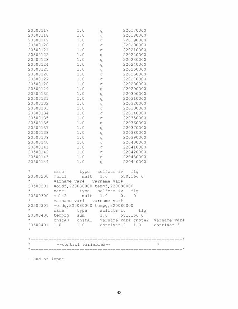
48
20500117 1.0 q 220170000 20500118 1.0 q 220180000 20500119 1.0 q 220190000 20500120 1.0 q 220200000 20500121 1.0 q 220210000 20500122 1.0 q 220220000 20500123 1.0 q 220230000 20500124 1.0 q 220240000 20500125 1.0 q 220250000 20500126 1.0 q 220260000 20500127 1.0 q 220270000 20500128 1.0 q 220280000 20500129 1.0 q 220290000 20500130 1.0 q 220300000 20500131 1.0 q 220310000 20500132 1.0 q 220320000 20500133 1.0 q 220330000 20500134 1.0 q 220340000 20500135 1.0 q 220350000 20500136 1.0 q 220360000 20500137 1.0 q 220370000 20500138 1.0 q 220380000 20500139 1.0 q 220390000 20500140 1.0 q 220400000 20500141 1.0 q 220410000 20500142 1.0 q 220420000 20500143 1.0 q 220430000 20500144 1.0 q 220440000 * name type sclfctr iv flg 20500200 mult1 mult 1.0 550.166 0 * varname var# varname var# 20500201 voidf,220080000 tempf,220080000 * name type sclfctr iv flg 20500300 mult2 mult 1.0 0. 0 * varname var# varname var# 20500301 voidg,220080000 tempg,220080000 * name type sclfctr iv flg 20500400 tempfg sum 1.0 551.166 0 * cnstA0 cnstA1 varname var# cnstA2 varname var# 20500401 1.0 1.0 cntrlvar 2 1.0 cntrlvar 3 * *===========================================================* * --control variables-- * *===========================================================* . End of input.

49
Appendix C
Beginner’s RELAP5-3D User Guide

50
Appendix C Beginner’s RELAP5-3D User Guide
C-1. Background RELAP5 is based on FORTRAN77, and parts have been updated to newer versions of FORTRAN.
RELAP originated as a program designed to model loss of coolant accidents (LOCAs) and other transients in nuclear power plants.
C-2. The Basics of RELAP RELAP is coded in a text editor. Information is entered onto a card. The card is reminiscent of the
ways data were literally entered into a computer on a physical data card. The card can now be thought of as a line of code. The pieces of data on a card are referred to as words. A card can only hold up to 80 characters. Words can be alphanumeric, real, or integer characters. Words act as pieces of data and can also act like a directory or a set of on or off switches that determine the meaning of the words of following cards.
C-3. Simplify Modeling in RELAP requires simplification of the actual structures. A model is started as simply as
possible. For example, a bundle of tubes in a heat exchanger can be modeled as one large tube with the same surface area, cross-sectional area, hydraulic diameter, and heated hydraulic diameter as the tube bundle.
C-4. Required/Optional entries It is important to understand which cards are required for the code to run and which are optional. In
the same way, it is vital to know when optional cars should be used and when they can be left out.
C-5. What Every User Should Know � Don’t use tabs.
� Use lower caps while coding. Comment can be capitalized.
� Break up sections and give them descriptive titles.
� Comment everything, including each word of a card. These comments will serve as a reminder during debugging.
� If using a fluid other than H2O, enter NEWATH for card 100. This adds a new module which allows for the use of other fluids.
� Before the code, write a brief description of the purpose of the code and the parameters used so that others may use the code with ease.
� Before the code, state the assumptions that have been made about the model.
� Asterisk (*) or a dollar symbol ($) is used to indicate comments.
� 0********** in the .”p” file shows where errors have occurred.
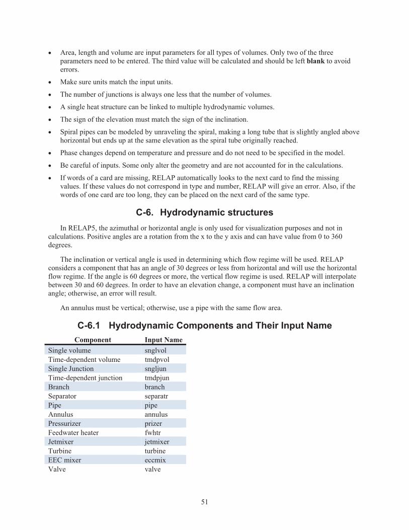
51
� Area, length and volume are input parameters for all types of volumes. Only two of the three parameters need to be entered. The third value will be calculated and should be left blank to avoid errors.
� Make sure units match the input units.
� The number of junctions is always one less that the number of volumes.
� A single heat structure can be linked to multiple hydrodynamic volumes.
� The sign of the elevation must match the sign of the inclination.
� Spiral pipes can be modeled by unraveling the spiral, making a long tube that is slightly angled above horizontal but ends up at the same elevation as the spiral tube originally reached.
� Phase changes depend on temperature and pressure and do not need to be specified in the model.
� Be careful of inputs. Some only alter the geometry and are not accounted for in the calculations.
� If words of a card are missing, RELAP automatically looks to the next card to find the missing values. If these values do not correspond in type and number, RELAP will give an error. Also, if the words of one card are too long, they can be placed on the next card of the same type.
C-6. Hydrodynamic structures In RELAP5, the azimuthal or horizontal angle is only used for visualization purposes and not in
calculations. Positive angles are a rotation from the x to the y axis and can have value from 0 to 360 degrees.
The inclination or vertical angle is used in determining which flow regime will be used. RELAP considers a component that has an angle of 30 degrees or less from horizontal and will use the horizontal flow regime. If the angle is 60 degrees or more, the vertical flow regime is used. RELAP will interpolate between 30 and 60 degrees. In order to have an elevation change, a component must have an inclination angle; otherwise, an error will result.
An annulus must be vertical; otherwise, use a pipe with the same flow area.
C-6.1 Hydrodynamic Components and Their Input Name Component Input Name
Single volume snglvol Time-dependent volume tmdpvol Single Junction sngljun Time-dependent junction tmdpjun Branch branch Separator separatr Pipe pipe Annulus annulus Pressurizer prizer Feedwater heater fwhtr Jetmixer jetmixer Turbine turbine EEC mixer eccmix Valve valve
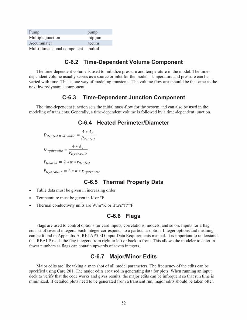
52
Pump pump Multiple junction mtpljun Accumulater accum Multi-dimensional component multid
C-6.2 Time-Dependent Volume Component The time-dependent volume is used to initialize pressure and temperature in the model. The time-
dependent volume usually serves as a source or inlet for the model. Temperature and pressure can be varied with time. This is one way of modeling transients. The volume flow area should be the same as the next hydrodynamic component.
C-6.3 Time-Dependent Junction Component The time-dependent junction sets the initial mass-flow for the system and can also be used in the
modeling of transients. Generally, a time-dependent volume is followed by a time-dependent junction.
C-6.4 Heated Perimeter/Diameter
]^6_76`�^a`b_c53d � � 8 ed�f 6_76`
]^a`b_c53d � � 8 ed�f a`b_c53d
f 6_76` � . 8 P 8 g 6_76`
f a`b_c53d � . 8 P 8 g a`b_c53d
C-6.5 Thermal Property Data � Table data must be given in increasing order
� Temperature must be given in K or °F
� Thermal conductivity units are W/m*K or Btu/s*ft*°F
C-6.6 Flags Flags are used to control options for card inputs, correlations, models, and so on. Inputs for a flag
consist of several integers. Each integer corresponds to a particular option. Integer options and meaning can be found in Appendix A, RELAP5-3D Input Data Requirements manual. It is important to understand that REALP reads the flag integers from right to left or back to front. This allows the modeler to enter in fewer numbers as flags can contain upwards of seven integers.
C-6.7 Major/Minor Edits Major edits are like taking a snap shot of all model parameters. The frequency of the edits can be
specified using Card 201. The major edits are used in generating data for plots. When running an input deck to verify that the code works and gives results, the major edits can be infrequent so that run time is minimized. If detailed plots need to be generated from a transient run, major edits should be taken often

53
depending on how long the code is actually running. Short transients require frequent major edits while long transients may not need as frequent edits for data resolution.
Minor edits specify individual parameters to be taken at the specified interval. Minor edits are useful if only one parameter or a parameter that is not on the major edits or needs to be taken often, but no other parameters are required.