model to text transformation: from uml statecharts to...
TRANSCRIPT

nicola migliorini
M O D E L T O T E X T T R A N S F O R M AT I O N : F R O MU M L S TAT E C H A RT S T O S C X M L B A S E D
C O N T R O L A P P L I C AT I O N S

U N I V E R S I TÀ D E G L I S T U D I D I F E R R A R AFA C O LTÀ D I I N G E G N E R I A
corso di laurea in ingegneria elettronica
M O D E L T O T E X T T R A N S F O R M AT I O N : F R O M U M LS TAT E C H A RT S T O S C X M L B A S E D C O N T R O L
A P P L I C AT I O N S
LaureandoNicola Migliorini
RelatoreProf. Marcello Bonfé
CorrelatoriDott. Gianluca Chiozzi
Ing. Luigi Andolfato
Anno accademico 2009/2010

Nicola Migliorini: Model to Text Transformation: from UML Stat-echarts to SCXML based control applications, Corso di laurea iningegneria elettronica, Università degli studi di Ferrara © March2011
supervisors:Prof. Marcello BonféDott. Gianluca ChiozziIng. Luigi Andolfato

Forget about the troubles of the past and live in the present.
Hakuna matata— Timon & Pumbaa
Dedicated to the loving memory of my father.
1951 – 1995

A B S T R A C T
That of UML statecharts is a very flexible formalism. UML state-charts are used to describe the logic of a software system. Theyare very useful in designing phase of the system and helpful inthe production of the documentation.
In this work I propose the realization of a code generatordeveloped at ESO. The tool take as input a UML state machineand the generated code will be the skeleton of an application.Developers must complete the application with hand-writtencode that bound the generated code to the desired target platform.This kind of approach promote the possibility to reuse models todevelop applications for different platforms.
S O M M A R I O
Quello degli UML statecharts è un formalismo molto flessibile.Gli statecharts vengono utilizzati per descrivere la logica di unsistema software. Sono molto utili in fase di progettazione e disupporto nella realizzazione della documentazione.
In questo lavoro presento la realizzazione di un code gen-erator sviluppato presso ESO. Il code generator è in grado diprodurre un’applicazione a partire dal modello UML di unamacchina a stati finiti. Il codice generato costituisce lo scheletrodi un’applicazione che lo sviluppatore dovrà completare con laparticolare implementazione che lega il tutto alla piattaformaper cui si sta sviluppando. Questo tipo di approccio garantisce epromuove la possibilità di riutilizzare i modelli per svilupparecodice su diverse piattaforme.
vii


A C K N O W L E D G M E N T S
Many thanks to everybody who helped me in this work. First ofall to Gianluca Chiozzi and Luigi Andolfato from whom I learneda lot. Heiko Sommer, Robert Karban, Reynald Bourtembourg, andall the people at ESO for the help and the good time spent whiledoing my work. Many thanks to my professors, Sergio Beghelliand Marcello Bonfé, for believing in my abilities and giving methis great opportunity.
A special thanks to my mom, my brother and all my familythat has always supported me in this long path. And thanks toPetra that has always been at my side, believing in me even inthe hardest moments.
Finally, many thanks to all the great new and old friends whohave accompanied me this far.
ix

C O N T E N T S
i understanding the topic 1
1 introduction 3
1.1 Objectives of this work 3
1.2 ESO 4
1.2.1 The organization 4
1.2.2 Main projects 4
1.3 Structure of the document 9
2 model driven development 11
2.1 Why we model 11
2.2 Models 13
2.3 The MDA approach 13
3 state machines 17
3.1 Statecharts 18
3.2 UML: a very general purpose definition for StateMachines 22
3.3 SCXML: a well defined standard 23
4 used tools 27
4.1 MagicDraw 28
4.2 Eclipse 29
4.3 EMF 30
4.3.1 Generator Workflow Component 31
4.3.2 Xpand 31
4.3.3 Check 32
4.3.4 Xtend 33
4.4 Apache SCXML and the Apache engine 33
ii developing the solution 35
5 model transformation 37
5.1 Problems 37
5.2 A proposal for UML to SCXML mapping 38
5.3 Comparison 39
5.3.1 Simple state 39
5.3.2 Initial pseudostate 40
5.3.3 Final pseudostate 41
5.3.4 Entry and exit actions 42
5.3.5 Transition 42
5.3.6 Internal Transition 43
5.3.7 Superstates and substates 44
5.3.8 History pseudostate 45
5.3.9 Activities 46
5.4 Custom actions 47
5.5 Summary 47
xi
xii contents
6 the code generator 49
6.1 The Generic State Machine Engine Architecture 49
6.1.1 Model Independent State Machine Engine 50
6.2 Implementation 52
6.2.1 Designing a model with MagicDraw 52
6.2.2 Transforming the model 53
6.2.3 Check 56
6.2.4 Xpand 58
6.2.5 Xtend 61
6.3 A running example: MasterComponent 63
6.3.1 Available substates 64
6.3.2 Substates of Online and Operational 65
6.3.3 A few modifications 65
6.3.4 The generated files 66
7 conclusions and future work 69
7.1 Targets achieved 69
7.2 What to do next? 70
iii appendix 71
a code listings 73
a.1 The code generator 73
bibliography 75
L I S T O F F I G U R E S
Figure 1 The VLTI Array on Paranal mountain. 6
Figure 2 The ALMA array at the high-elevation Ar-ray Operations Site. 7
Figure 3 A render of the E-ELT project. 8
Figure 4 OMG’s Model Driven Architecture fromOMG website[23]. 15
Figure 5 A simple state machine 17
Figure 6 A simple statechart 18
Figure 7 States and transitions 19
Figure 8 Use of a composite state 19
Figure 9 History pseudo-states. 20
Figure 10 Use of orthogonal regions 21
Figure 11 Use of actions and activities. 21
Figure 12 A collage of UML diagrams. 22
Figure 13 Stopwatch example from Apache Commonswebsite. 23
Figure 14 A screnshot from MagicDraw. 28
Figure 15 An overview of the Eclipse architecture. 29
Figure 16 Structure of an Xpand file. 32
Figure 17 Initial pseudostate 40
Figure 18 Which substate is the first entered? 41
Figure 19 Final pseudostate 42
Figure 20 A transition with all its elements. 43
Figure 21 A configuration not supported by the ApacheSCXML engine. 44
Figure 22 The workaround proposed. 45
Figure 23 The history element with a default state. 46
Figure 24 Generic State Machine Engine Data Flow[12]. 49
Figure 25 This activity diagram represents the work-flow of the code generator. 54
Figure 26 The MasterComponent State Machine. 63
xiii
L I S T O F TA B L E S
Table 1 State 39
Table 2 Initial pseudostate 40
Table 3 Final pseudostate 41
Table 4 Didascalia elenco tabelle 42
Table 5 Transition 42
Table 6 Internal transition 43
Table 7 Superstates 44
Table 8 Substates 45
Table 9 History pseudostate 45
Table 10 Activities 47
L I S T I N G S
Listing 1 SCXML file for the stopwatch example 25
Listing 2 Workflow file 55
Listing 3 constraints.chk file 56
Listing 4 Root.xpt file 58
Listing 5 The Root block in FSMSCxml.xpt 58
Listing 6 The ExploreState block in FSMSCxml.xpt 59
Listing 7 The ExploreCompState block in FSMSCxml.xpt 59
Listing 8 The ExploreOrthState block in FSMSCxml.xpt 60
Listing 9 The ExploreActions block in FSMSCxml.xpt 61
Listing 10 Some functions from ScxmlUtil.ext file 61
A C R O N Y M S
ACS ALMA Common Software
ALMA Atacama Large Millimeter/Sub-Millimeter Array
ATs Auxiliary Telescopes
xiv
acronyms xv
CWM Common Warehouse Metamodel
CASE Computer Aided Software Engineering
E-ELT European Extremely Large Telescope
ESO European Southern Observatory
GSME Generic State Machine Engine
MDA Model Driven Architecture
MDD Model Driven Development
MOF Meta Object Facility
OCL Object Constraint Language
OMG Object Management Group
PIM Platform Independent Models
PSM Platform Specific Models
SDD Software Development Division
UML Unified Modeling Language
UTs Unit Telescopes
VLT Very Large Telescope
VLTI Very Large Telescope Interferometer
XMI XML Metadata Interchange

Part I
U N D E R S TA N D I N G T H E T O P I C

1I N T R O D U C T I O N
Contents1.1 Objectives of this work 31.2 ESO 4
1.2.1 The organization 4
1.2.2 Main projects 4
1.3 Structure of the document 9
In the 60 years of history of the programming languages, analways constant trend has been the will to raise the level of ab-straction. First we passed from programming codes to low levellanguages like Assembly. Then came out the first procedurallanguages (FORTRAN and COBOL), followed by the functionallanguages like LISP. Coupled with the evolution of the hardware,software became more and more complex. The dimensions ofapplications grew, highlighting the limits of the functional ap-proaches. After the structured paradigm of PASCAL and C, thenext step was the incremental development: with the collabo-ration of teams of developers, small pieces of code were puttogether. This was the base for the object oriented paradigm. Codereuse was one of the main targets[13].
Nowadays a medium application consist of hundreds of thou-sand (if not millions) of line of code. Is not thinkable to write itwithout the use of tools and an appropriate approach. Again thetrend is to raise the level of abstraction. With the Model DrivenDevelopment (MDD) approach, developers have appropriate toolsto write and maintain huge applications. Furthermore MDD of-fers a good support in developing documentation. With the helpof automatic code generation repetitive tasks are avoided by de-velopers. They can focus on the logic of the application, thinkingabout the big picture, and letting the code generator to deal withthe implementations details.
With this kind of strategies and a correct approach, time issaved and resources are used in a better way.
1.1 objectives of this work
This project aims to the creation of a reusable State MachineCode Generator. The main purpose is to have a state machineimplementation that allows execution and control of the state ma-chine logic. As the code generator must be reusable on different
3
4 introduction
platform the choice of using open and well defined technologieslike CORBA, UML and XML is obvious. The target is to obtaina running application starting from a state machine model. Theobtained application will be the skeleton on which developerswill build the software with the implementations details.
1.2 eso
1.2.1 The organization
The European Southern Observatory (ESO) is an intergovern-mental research organization for astronomy, composed and sup-ported by fifteen countries. Established in 1962 with an objectiveSince December
2010 Brazil is also aparticipant
to provide state-of-the-art facilities and access to the sky of thesouthern hemisphere to European astronomers, it is famous forbuilding and operating some of the largest and most techno-logically advanced telescopes in the world, such as the NewTechnology Telescope located at La Silla Observatory, the tele-scope that pioneered active optics technology, and the VLTI (VeryLarge Telescope Interferometer) located at Paranal.
Its numerous observing facilities have enabled many astro-nomical discoveries, and produced several astronomical catalogs.Among the more recent discoveries is the discovery of the farthestgamma-ray burst and the evidence for a black hole at the center ofour Galaxy, the Milky Way. In 2004, the VLT allowed astronomersto obtain the first picture of an extra-solar planet, orbiting abrown dwarf 173 light-years away. The VLT has also discoveredthe candidate farthest galaxy ever seen by humans[10].
1.2.2 Main projects
All ESO observation facilities are located in Chile (because of theneed to study the Southern skies and the unique atmosphericconditions of the Atacama Desert, ideal for astronomy), whilethe headquarters, with the scientific, technical and administrativecenter of the organization, are located in Garching bei München,Germany. ESO operates three major observatories in Chile’s Ata-cama desert, one of the driest places on Earth:
• La Silla Observatory, which hosts eighteen telescopes (threeof them are still operated by ESO for use by the astronomicalcommunity), a 3.6 horseshoe mount telescope(mostly usedfor infrared spectroscopy and for the search of extra-solarplanets) and other less important facilities
• Paranal Observatory, which hosts the Very Large Tele-scope,the VISTA telescope and the italian VST (VLT SurveyTelescope)
1.2 eso 5
• Llano de Chajnantor Observatory, which hosts the APEX(Atacama Pathfinder Experiment) submillimeter telescopeand where ALMA, the Atacama Large Millimeter Array,is currently under construction in a collaboration betweenEast Asia (Japan and Taiwan), Europe (ESO), North America(USA and Canada), and Chile.
Each year, about 2000 proposals are made for the use of ESOtelescopes, requesting between four and six times more nightsthan are available. ESO is one of the most productive ground-based observatories in the world, which annually results in manypeer-reviewed publications: in 2009 alone, more than 650 refereedpapers based on ESO data were published. Moreover, researcharticles based on VLT data are in the mean quoted twice as oftenas the average. The very high efficiency of the ESO’s "sciencemachines" now generates huge amounts of data at a very highrate. These are stored in a permanent Science Archive Facility atESO headquarters. The archive now contains more than 1.5 mil-lion images or spectra with a total volume of about 65 terabytes(65,000,000,000,000 bytes) of data[10].
ESO has also hosted the European Coordinating Facility for theHubble Space Telescope, a collaboration between ESA and NASA.The HST-ECF has been a long-term, space-based observatory. In20 years of activities, in many ways Hubble has revolutionizedmodern astronomy, by not only being an efficient tool for makingnew discoveries, but also by driving astronomical research ingeneral. The ST-ECF has closed and ceased operations on 31
December 2010.
1.2.2.1 VLTI
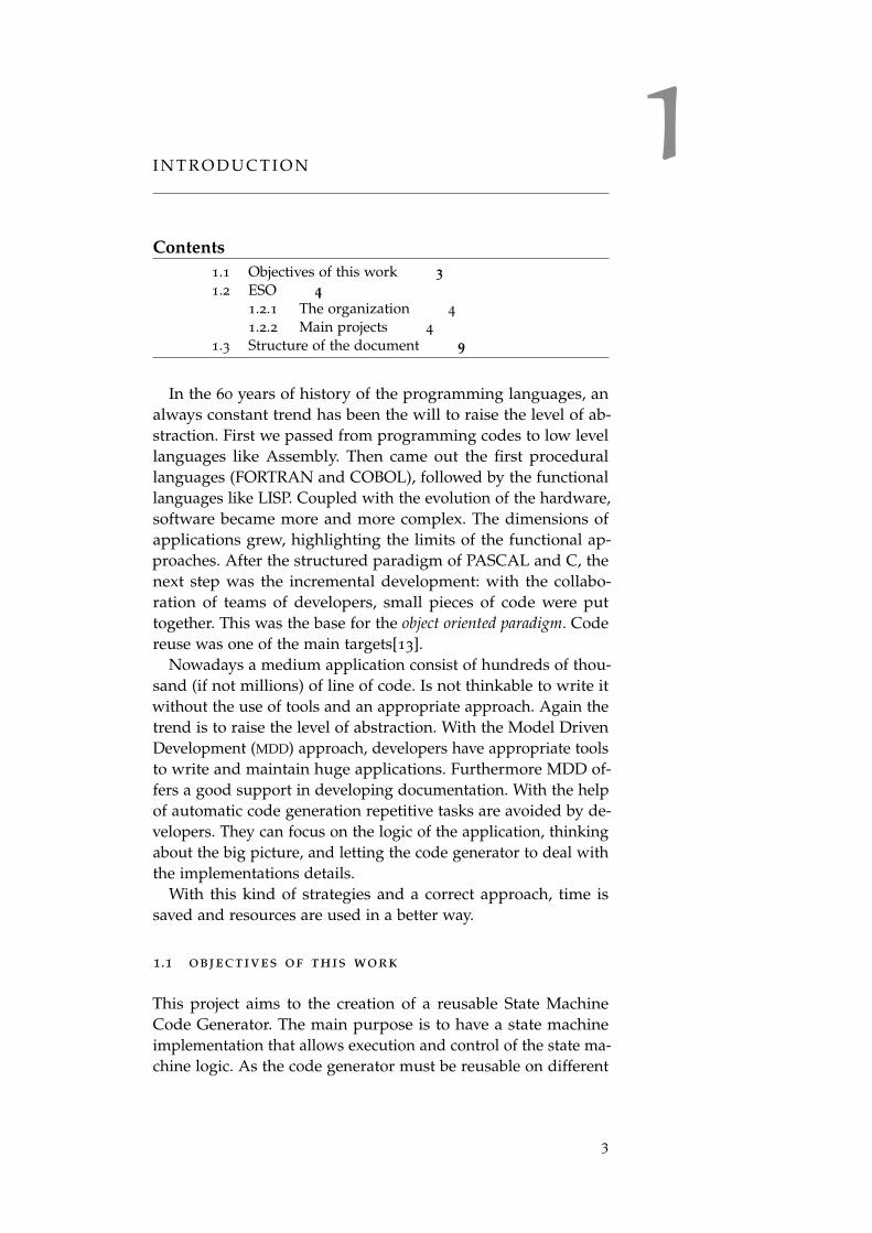
The Very Large Telescope (VLT) at Cerro Paranal is ESO’s premiersite for observations in the visible and infrared. The Very LargeTelescope Interferometer (VLTI) consists in the coherent combi-nation of the four VLT Unit Telescopes and of the four movableAuxiliary Telescopes.The VLTI provides both a high sensitivityas well as milli-arcsec angular resolution using baselines of up to200 meters length.
The four 8.2 meters Unit Telescopes (UTs) and the four 1.8meters Auxiliary Telescopes (ATs) constitute the light collectingelements of the VLTI. The UTs are set on fixed locations whilethe ATs can be relocated on 30 different stations. The telescopescan be combined in groups of two or three. After the light beamshave passed through a complex system of mirrors and the Delaylines, the combination at near- and mid-infrared is performedby the instruments. A complex and high performance dual-feedsystem that allows Phase Referenced Imaging and Micro Arcsec-ond Astrometry on the VLTI will be available soon. Due to its
6 introduction
Figure 1: The VLTI Array on Paranal mountain.
characteristics, the VLTI has become a very attractive mean forscientific research on various objects like many stars in the solarneighborhood or extragalactic objects[9].
The VLT Common Software is the development software infras-tructure platform for VLT applications. It provides the buildingblocks for all applications and has been used by all internal andexternal development teams. The size of the VLT control software,including telescope control software, is about 1.5 million linesof code and might become about 3 million lines when the fullinstrumentation complement is ready [15]. The VLT commonsoftware consists of a layer of software over the Unix operatingsystem, in the case of workstations and on top of the VxWorksoperating system, for the Local Control Unit (LCU) microproces-sors. It provides mainly common services, like an architectureindependent message system, a real-time database for all tele-scope and instrument parameters, error and logging systems anda large number of utilities and tools. The languages used are C(lower layers) and C++ (and Object Oriented concepts) on theworkstation side, while the code running on the microprocessorsis written exclusively in C. The User Interfaces on the worksta-tions are built using the VLT Panel Editor, which is based onTcl/Tk[11].
1.2.2.2 ALMA
Atacama Large Millimeter/Sub-Millimeter Array (ALMA) is ajoint project between astronomical organizations of Europe (ESO),
1.2 eso 7
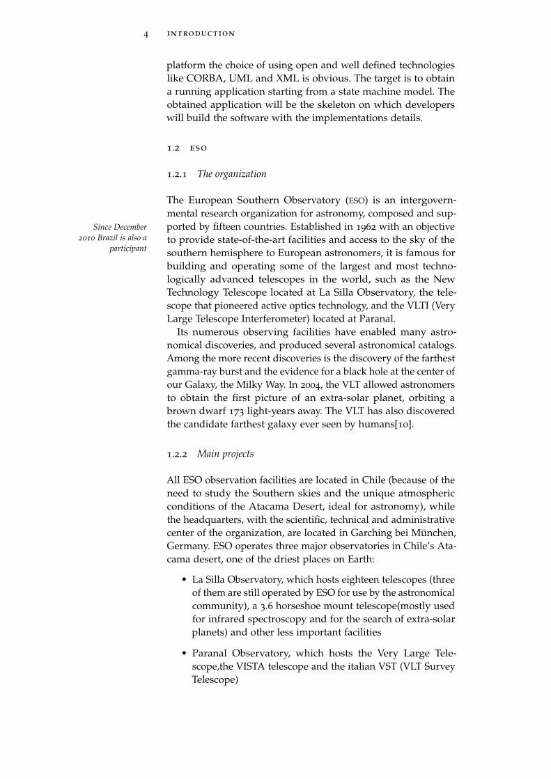
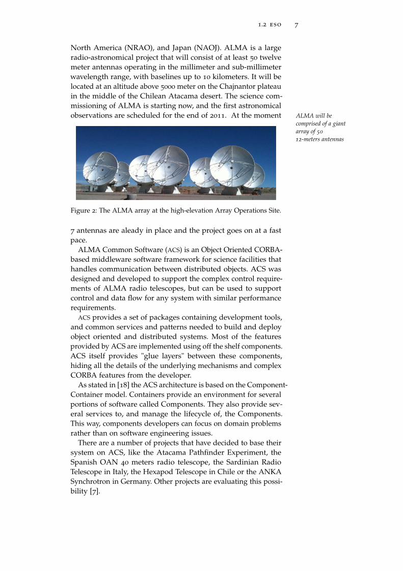
North America (NRAO), and Japan (NAOJ). ALMA is a largeradio-astronomical project that will consist of at least 50 twelvemeter antennas operating in the millimeter and sub-millimeterwavelength range, with baselines up to 10 kilometers. It will belocated at an altitude above 5000 meter on the Chajnantor plateauin the middle of the Chilean Atacama desert. The science com-missioning of ALMA is starting now, and the first astronomicalobservations are scheduled for the end of 2011. At the moment ALMA will be
comprised of a giantarray of 5012-meters antennas
Figure 2: The ALMA array at the high-elevation Array Operations Site.
7 antennas are aleady in place and the project goes on at a fastpace.
ALMA Common Software (ACS) is an Object Oriented CORBA-based middleware software framework for science facilities thathandles communication between distributed objects. ACS wasdesigned and developed to support the complex control require-ments of ALMA radio telescopes, but can be used to supportcontrol and data flow for any system with similar performancerequirements.
ACS provides a set of packages containing development tools,and common services and patterns needed to build and deployobject oriented and distributed systems. Most of the featuresprovided by ACS are implemented using off the shelf components.ACS itself provides "glue layers" between these components,hiding all the details of the underlying mechanisms and complexCORBA features from the developer.
As stated in [18] the ACS architecture is based on the Component-Container model. Containers provide an environment for severalportions of software called Components. They also provide sev-eral services to, and manage the lifecycle of, the Components.This way, components developers can focus on domain problemsrather than on software engineering issues.
There are a number of projects that have decided to base theirsystem on ACS, like the Atacama Pathfinder Experiment, theSpanish OAN 40 meters radio telescope, the Sardinian RadioTelescope in Italy, the Hexapod Telescope in Chile or the ANKASynchrotron in Germany. Other projects are evaluating this possi-bility [7].
8 introduction
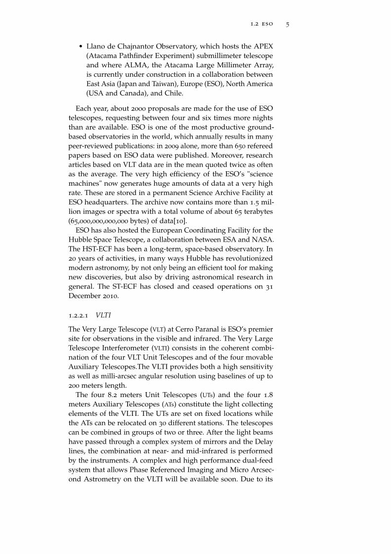
1.2.2.3 E-ELT
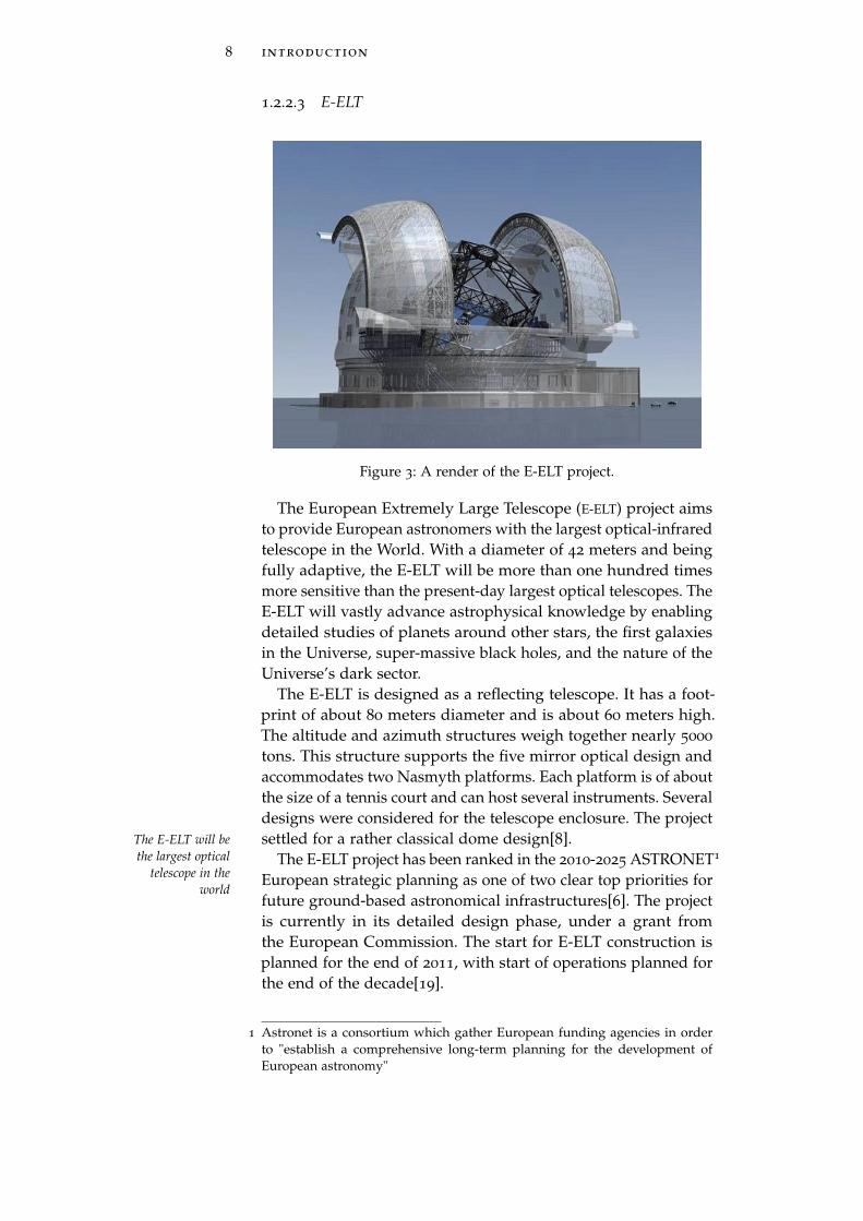
Figure 3: A render of the E-ELT project.
The European Extremely Large Telescope (E-ELT) project aimsto provide European astronomers with the largest optical-infraredtelescope in the World. With a diameter of 42 meters and beingfully adaptive, the E-ELT will be more than one hundred timesmore sensitive than the present-day largest optical telescopes. TheE-ELT will vastly advance astrophysical knowledge by enablingdetailed studies of planets around other stars, the first galaxiesin the Universe, super-massive black holes, and the nature of theUniverse’s dark sector.
The E-ELT is designed as a reflecting telescope. It has a foot-print of about 80 meters diameter and is about 60 meters high.The altitude and azimuth structures weigh together nearly 5000
tons. This structure supports the five mirror optical design andaccommodates two Nasmyth platforms. Each platform is of aboutthe size of a tennis court and can host several instruments. Severaldesigns were considered for the telescope enclosure. The projectsettled for a rather classical dome design[8].The E-ELT will be
the largest opticaltelescope in the
world
The E-ELT project has been ranked in the 2010-2025 ASTRONET1
European strategic planning as one of two clear top priorities forfuture ground-based astronomical infrastructures[6]. The projectis currently in its detailed design phase, under a grant fromthe European Commission. The start for E-ELT construction isplanned for the end of 2011, with start of operations planned forthe end of the decade[19].
1 Astronet is a consortium which gather European funding agencies in orderto "establish a comprehensive long-term planning for the development ofEuropean astronomy"
1.3 structure of the document 9
The software framework is actually being defined[27]. Twoof the most important aspects of the E-ELT’s development arethe control of high precision optics over the huge scale of thetelescope and the design of an efficient suite of instruments toachieve the E-ELT’s ambitious goals. All starts from a flexiblesuite of tools and from a software infrastructure used to configure,control and acquire data from E-ELT instruments.
1.3 structure of the document
This document is organized in parts, each of which is divided inchapters, with the the following structure:
• Part one: Understanding the topics presents an overviewof the topics touched developing the code generator, objectof my thesis
– Chapter 2 introduces the concept of Model Driven
Development
– Chapter 3 is a presentation of the state machine andthe different incarnations in languages like UML andSCXML. A first introduction to the Apache SCXMLengine is also in this chapter.
– Chapter 4 outlines the tools used in the developmentof the code generator.
• Part two: Developing the solution outlines the work doneat ESO to project and develop the code generator.
– In Chapter 5 a first mapping from UML to SCXML ispresented
– Chapter 6 examines the code generator and a runningexample developed at ESO for the components of acontrol system
– Chapter 7 keeps an eye on the possible future improve-ments of my work

2M O D E L D R I V E N D E V E L O P M E N T
Contents2.1 Why we model 112.2 Models 132.3 The MDA approach 13
Model Driven Development focuses on developing softwarecomponents using abstractions of software systems, i.e. models.Models are also used, with a certain amount of details, to describea software application. MDD is meant to simplify the process ofdesign the components of the system and the relations betweendifferent modules.
2.1 why we model
With the support of a graphical model representation, the wholestructure of the application is easy to understand at a glance andalso newcomers can easily jump in a work in progress. This helpsa lot in projects where a big team is involved in the development.Models help to keep the focus on details without loosing the bigpicture and make the collaboration much easier. Models are thenconverted into code. The conversion can be made manually orautomatically, using tools designed for this. Automatic code gen-eration from models reduces the manually written lines of codeand with this the number of errors per line of code. Code reuseis encouraged and made easier. In fact, mostly in big projects, alarge number of line of code is repeated in various components.Having a tool that can do this repetitive work not only leadsto an increased productivity, but also to a coherent and cleanercode. In addition enhancements made on the code generator arepropagated on all the generated components. This is a strengthbut also a critical point since if a bug is present on the codegenerator all the generated code will be affected.
But the advantages of the MDD are also others. With an higherlevel of abstraction developers can forget about the implemen-tation details. Specify less and generate more. Also this has another side of the coin: less control on detail leads to rigidity.
The Model approach is strongly supported by the Object Man-agement Group (OMG) that, supplying open and vendor-neutralinteroperability specifications, provides a basis for developingthis strategy. With the Model Driven Architecture (MDA), OMG
11
12 model driven development
offers "an architecture that makes interoperability central to yourinfrastructure" [25]. The OMG Model Driven Architecture encap-sulates many important ideas, most notably the notion that realbenefits can be obtained by using visual modeling languages tointegrate the huge diversity of technologies used in the develop-ment of software systems. In the era of Internet and web services,achieving interoperability is a necessity. With the model approachdevelopers can make a separation between the specification ofsystem functionality and the specification of the implementationof that functionality on a given platform. In MDA this is a key dis-tinction that is fundamental and leads to Platform IndependentModels (PIM) and Platform Specific Models (PSM). PIM specifiesservices and interfaces that the software systems must provide,independent of software technology platforms. The PIM is furtherDivision between
what is dependentfrom the platformand what belongs
only to the logic ofthe system
refined to a PSM which describes the realization of the softwaresystems with respect to the chosen software technology platforms.Again [25] gives a definition for both these kinds of models andstates that modeling staying away from platform specific detailsmakes things easier when implementing the applications fordifferent platforms. The integration and interoperability are eas-ier to achieve thinking with platform independent models, andthereafter easier to implement with platform dependent details.In addition, the model approach faces also the problem of theproliferation of middleware frameworks. Big enterprises have todeal with different middleware platforms and again the neces-sity to achieve interoperability is evident. Each department ofthe enterprise may have different requirements for projects, orsimply, a mix of technology to deal with. It’s not worthy to portdifferent already working applications to a single middlewareplatform if it’s possible to make them cooperate with a smartproject mentality. These are the main reasons that make the modelapproach so important. With a well designed model developersgain the flexibility and ability to obtain valid code even when theinfrastructure changes over time. And as the whole approach isplatform independent, when a new and better technology will beavailable, integrating this on the project will be an easy step[16].
Let’s look at this question from the point of view of the con-struction trade. Architects design buildings. Builders use thedesigns to create buildings. The more complicated the build-ing, the more critical the communication between architect andbuilder. Blueprints are the standard graphical language that botharchitects and builders must learn as part of their trade.
"Writing software is not unlike constructing a building. Themore complicated the underlying system, the more critical thecommunication among everyone involved in creating and deploy-ing the software"[25]. In the past decade, the Unified ModelingLanguage (UML) has emerged as the software blueprint language
2.2 models 13
for analysts, designers, and programmers alike. It is now part ofthe software trade. The UML gives everyone from business analystto designer to programmer a common vocabulary when talkingabout software design.
2.2 models
But what exactly is a model? A model is a representation of a In a model only therelevant aspect of thesystem arerepresented
system. A model group a set of concepts about the subject itrepresent. There concepts are called abstractions. Models consistof objects that interact by sending each other messages. Thinkingof objects as live entities, they have things they know (attributes)and things they can do (behaviors or operations). The values ofan object’s attributes determine its state. But the strength of themodel representation is the possibility to simplify the reality. It’snot possible to represent every detail of the subject, as the amountof informations is to big. Focusing on the relevant informationsrelated to the problem we are facing, helps on the understandingof the problem itself and leads to a solution in a easier way. Thedeveloper must choose the level of details to be described. Andthis is the key to manage the complexity involved in systemdevelopment.
2.3 the mda approach
In early 2002, the OMG described the general principles forMDA[21]: MDA: the approach
to model drivendevelopmentproposed by OMG
"The MDA defines an approach to IT system specifica-tion that separates the specification of system functionalityfrom the specification of the implementation of that func-tionality on a specific technology platform. To this end, theMDA defines an architecture for models that provides aset of guidelines for structuring specifications expressed asmodels."
"The MDA approach and the standards that support itallow the same model specifying system functionality tobe realized on multiple platforms through auxiliary map-ping standards, or through point mappings to specific plat-forms, and allows different applications to be integrated byexplicitly relating their models, enabling integration andinteroperability and supporting system evolution as plat-form technologies come and go."
In other words with MDA the development of a software sys-tem is based on the separation of the business aspects from theimplementation aspects. Modelling these different aspects with
14 model driven development
various level of abstraction, focusing on models rather than oncode, and derive the code from models with automatic generationwill reduce complexity.
MDA provides a set of specifications that support the modelingof functional aspects of a business application in the form ofa Platform Independent Models. As its name implies, a PIM isa formal model that is independent of any specific implemen-tation technologies. So the same PIM ultimately could be usedto develop an implementation based on Java, or .Net, or anyother platform. The Model Driven Architecture then provides asystematic way to map a PIM to one or more Platform SpecificModels. As its name implies, a PSM is targeted for a particularcomputing platform, such as J2EE or .Net. Using other featuresof MDA, the resulting PSM then can be used to generate code,data structures, configuration information, as necessary for thechosen deployment technologies.
Using MDA, the development of a system can be faster. PIMThe key concepts ofMDA are
abstraction andautomation
can be developed by business analysts with little or no technicalbackgroung but with a good knowledge of the domain of theapplication. Advanced programmers can focus on the implemen-tation details of the application.
In addtion MDA can be used to integrate applications betweendifferent platforms, encouraging the reuse of elements acrossdifferent frameworks.
But all the advantages have a price. The heavy use of standardsis required to achieve interoperabilty. Developers must be prag-matic in thei approach of implementing MDA. The use of alreadyexisting solutions and well accepted approaches is the base ofthis development strategy.
Portability, cross-platform interoperability and platform in-dependence are achieved through the use of such well knownstandards as CORBA or XML. The qualities of portability, in-teroperability, and platform independence lead to the domainspecificity, the ability to focus on solving particular business prob-lems. This means developping the best solutions beeing aware ofthe domain of the application: a bank, an hospital or a space ship.In either case there is no need to worry about how these solutionsshould be coded, or how they will run on a specific platform.That set of worries is deferred till later in the development.
With the classic approach each project is cartried out by a teamof developers that must have a knowledge of the problem domainand of the platform adopted. If for some reason the team breaksup, or leave the company all the knowledge is lost. With MDA
also the teams are separated. The platform knowledge and thedomain knoledge are divided and each team take care of his ownarea. If something change at the business level, domain expertscan update the corresponding models. Platform experts provide
2.3 the mda approach 15
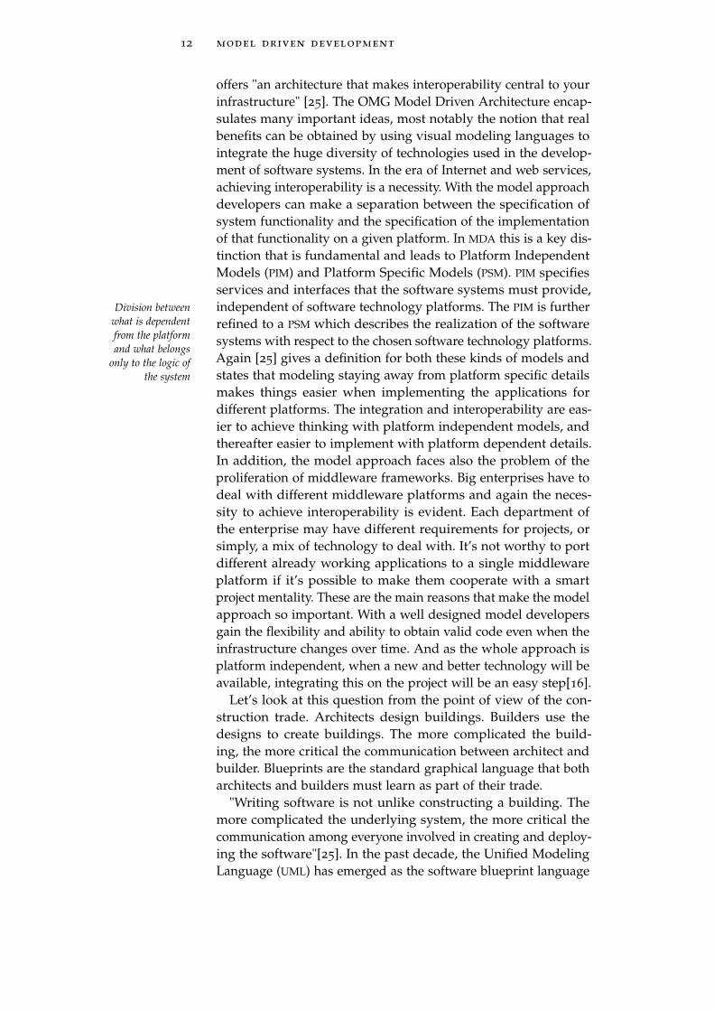
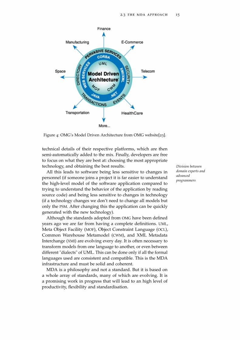
Figure 4: OMG’s Model Driven Architecture from OMG website[23].
technical details of their respective platforms, which are thensemi-automatically added to the mix. Finally, developers are freeto focus on what they are best at: choosing the most appropriatetechnology, and obtaining the best results. Division between
domain experts andadvancedprogrammers
All this leads to software being less sensitive to changes inpersonnel (if someone joins a project it is far easier to understandthe high-level model of the software application compared totrying to understand the behavior of the application by readingsource code) and being less sensitive to changes in technology(if a technology changes we don’t need to change all models butonly the PSM. After changing this the application can be quicklygenerated with the new technology).
Although the standards adopted from OMG have been definedyears ago we are far from having a complete definitions. UML,Meta Object Facility (MOF), Object Constraint Language (OCL),Common Warehouse Metamodel (CWM), and XML MetadataInterchange (XMI) are evolving every day. It is often necessary totransform models from one language to another, or even betweendifferent "dialects" of UML. This can be done only if all the formallanguages used are consistent and compatible. This is the MDAinfrastructure and must be solid and coherent.
MDA is a philosophy and not a standard. But it is based ona whole array of standards, many of which are evolving. It isa promising work in progress that will lead to an high level ofproductivity, flexibility and standardisation.

3S TAT E M A C H I N E S
Contents3.1 Statecharts 183.2 UML: a very general purpose definition for
State Machines 223.3 SCXML: a well defined standard 23
"A finite state machine is an abstract machine that de-fines a finite set of conditions of existence (called "states"),a set of behaviors or actions performed in each of thosestates, and a set of events which cause changes in statesaccording to a finite and well-defined rule set"
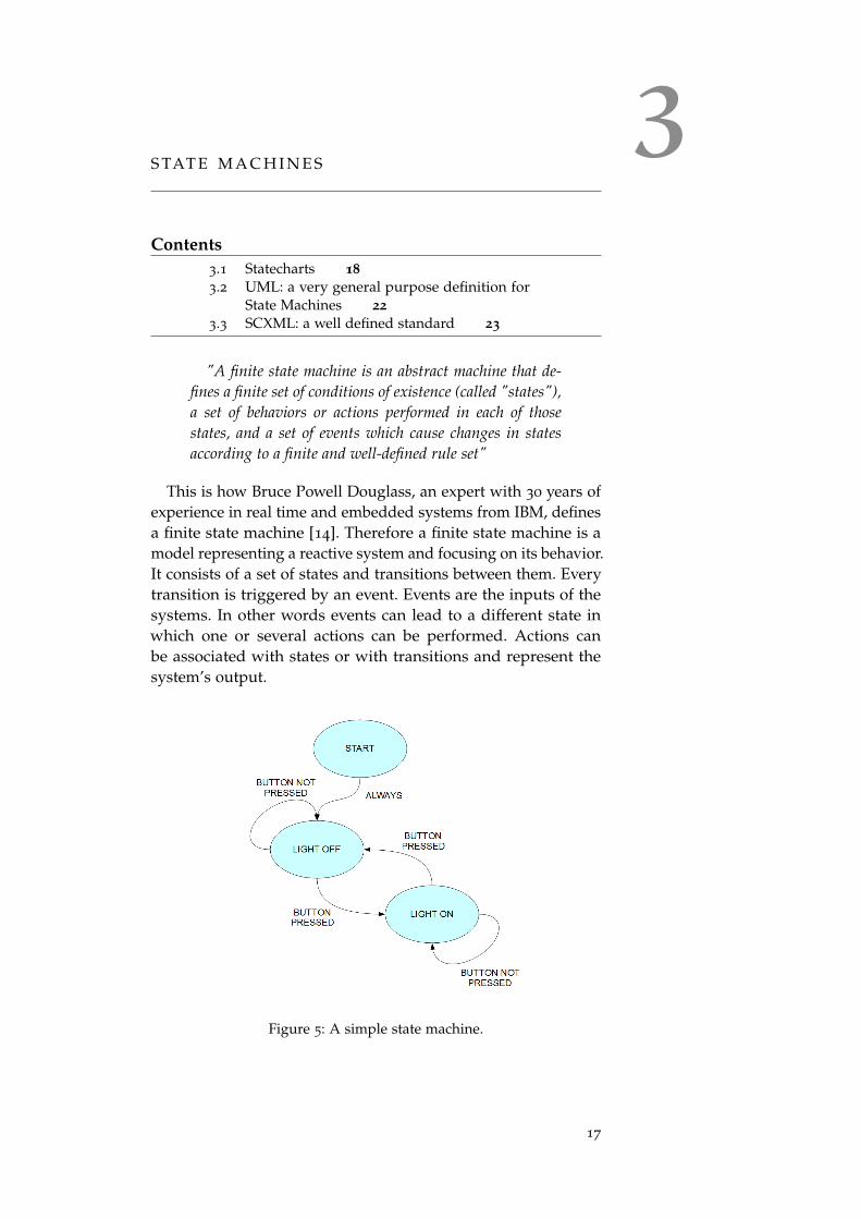
This is how Bruce Powell Douglass, an expert with 30 years ofexperience in real time and embedded systems from IBM, definesa finite state machine [14]. Therefore a finite state machine is amodel representing a reactive system and focusing on its behavior.It consists of a set of states and transitions between them. Everytransition is triggered by an event. Events are the inputs of thesystems. In other words events can lead to a different state inwhich one or several actions can be performed. Actions canbe associated with states or with transitions and represent thesystem’s output.
Figure 5: A simple state machine.
17
18 state machines
In Other words a state machine is a kind of "black box" thatresponds to external stimuli. Given the current state of the device,a given input leads to a particular output and to a new state.All this is represented using simple diagrams. These diagramsare similar to a flow graph. Fig.5 shows a simple state transitiondiagram of a switch.
3.1 statecharts
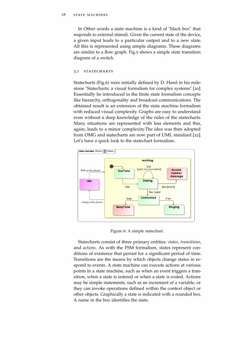
Statecharts (Fig.6) were initially defined by D. Harel in his mile-stone "Statecharts: a visual formalism for complex systems" [20].Essentially he introduced in the finite state formalism conceptslike hierarchy, orthogonality and broadcast communications. Theobtained result is an extension of the state machine formalismwith reduced visual complexity. Graphs are easy to understandeven without a deep knowledge of the rules of the statecharts.Many situations are represented with less elements and this,again, leads to a minor complexity.The idea was then adoptedfrom OMG and statecharts are now part of UML standard [22].Let’s have a quick look to the statechart formalism.
Figure 6: A simple statechart.
Statecharts consist of three primary entities: states, transitions,and actions. As with the FSM formalism, states represent con-ditions of existence that persist for a significant period of time.Transitions are the means by which objects change states in re-spond to events. A state machine can execute actions at variouspoints in a state machine, such as when an event triggers a tran-sition, when a state is entered or when a state is exited. Actionsmay be simple statements, such as an increment of a variable, orthey can invoke operations defined within the context object orother objects. Graphically a state is indicated with a rounded box.A name in the box identifies the state.
3.1 statecharts 19
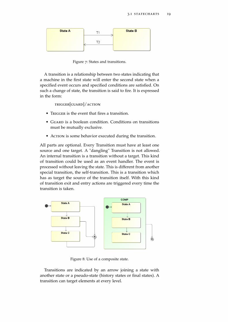
Figure 7: States and transitions.
A transition is a relationship between two states indicating thata machine in the first state will enter the second state when aspecified event occurs and specified conditions are satisfied. Onsuch a change of state, the transition is said to fire. It is expressedin the form:
trigger[guard]/action
• Trigger is the event that fires a transition.
• Guard is a boolean condition. Conditions on transitionsmust be mutually exclusive.
• Action is some behavior executed during the transition.
All parts are optional. Every Transition must have at least onesource and one target. A "dangling" Transition is not allowed.An internal transition is a transition without a target. This kindof transition could be used as an event handler. The event isprocessed without leaving the state. This is different from anotherspecial transition, the self-transition. This is a transition whichhas as target the source of the transition itself. With this kindof transition exit and entry actions are triggered every time thetransition is taken.
Figure 8: Use of a composite state.
Transitions are indicated by an arrow joining a state withanother state or a pseudo-state (history states or final states). Atransition can target elements at every level.
20 state machines
A first useful difference with the state machines is the conceptof complex states. A super-state could be defined; this state iden-tifies some features common to the sub-states. The main idea isto group some states and to reduce the number of transitionsfrom the single states. Instead of having a transition from everysub-state, a single arrow can leave the super-state. This featurecan represent an XOR between the inner states.
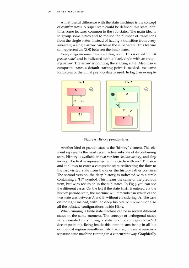
Every diagram must have a starting point. This is called "Initialpseudo-state" and is indicated with a black circle with an outgo-ing arrow. The arrow is pointing the starting state. Also insidecomposite states a default starting point is needed. the sameformalism of the initial pseudo-state is used. In Fig.8 an example.
Figure 9: History pseudo-states.
Another kind of pseudo-state is the "history" element. This ele-ment represents the most recent active substate of its containingstate. History is available in two version: shallow history, and deephistory. The first is represented with a circle with an "H" insideand it allows to enter a composite state redirecting the flow tothe last visited state from the ones the history father contains.The second version, the deep history, is indicated with a circlecontaining a "H*" symbol. This means the same of the previousitem, but with recursion in the sub-states. In Fig.9 you can seethe different cases. On the left if the state Hist1 is entered via thehistory pseudo-state, the machine will remember in which of thetwo state was between A and B, without considering B1. The caseon the right instead, with the deep history, will remember alsoall the substate configurations inside Hist2.
When running, a finite state machine can be in several differentstates in the same moment. The concept of orthogonal statesis represented by splitting a state in different regions (ANDdecomposition). Being inside this state means being in all hisorthogonal regions simultaneously. Each region can be seen as aseparate state machine running in a concurrent way. Graphically
3.1 statecharts 21
Figure 10: Use of orthogonal regions.
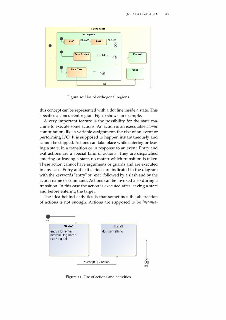
this concept can be represented with a dot line inside a state. Thisspecifies a concurrent region. Fig.10 shows an example.
A very important feature is the possibility for the state ma-chine to execute some actions. An action is an executable atomiccomputation, like a variable assignment, the rise of an event orperforming I/O. It is supposed to happen instantaneously andcannot be stopped. Actions can take place while entering or leav-ing a state, in a transition or in response to an event. Entry andexit actions are a special kind of actions. They are dispatchedentering or leaving a state, no matter which transition is taken.These action cannot have arguments or guards and are executedin any case. Entry and exit actions are indicated in the diagramwith the keywords "entry" or "exit" followed by a slash and by theaction name or command. Actions can be invoked also during atransition. In this case the action is executed after leaving a stateand before entering the target.
The idea behind activities is that sometimes the abstractionof actions is not enough. Actions are supposed to be instanta-
Figure 11: Use of actions and activities.
22 state machines
neous: once started, the state machine will wait until the actionis finished. Some executions could not be represented in thisway. They can take a finite amount of time and the developer couldwant to consider it. Furthermore could be necessary to block anexecution because, for example, in the meantime we are leavinga state. This can be done with the Do-Activities. On the diagramthis is identified with the "do" keyword followed by a slash andthe invocation for the activity. On Fig.11 you can see a summaryon how to use actions and activities.
3.2 uml : a very general purpose definition for state
machines
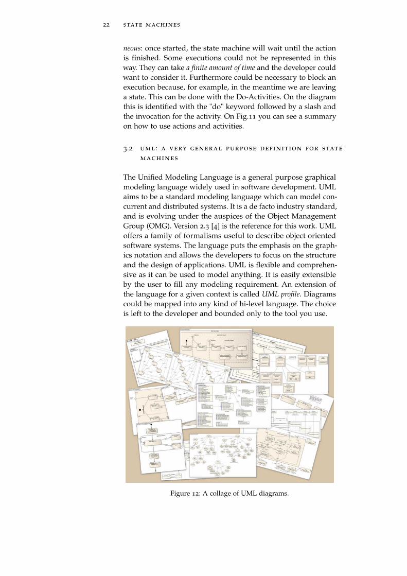
The Unified Modeling Language is a general purpose graphicalmodeling language widely used in software development. UMLaims to be a standard modeling language which can model con-current and distributed systems. It is a de facto industry standard,and is evolving under the auspices of the Object ManagementGroup (OMG). Version 2.3 [4] is the reference for this work. UMLoffers a family of formalisms useful to describe object orientedsoftware systems. The language puts the emphasis on the graph-ics notation and allows the developers to focus on the structureand the design of applications. UML is flexible and comprehen-sive as it can be used to model anything. It is easily extensibleby the user to fill any modeling requirement. An extension ofthe language for a given context is called UML profile. Diagramscould be mapped into any kind of hi-level language. The choiceis left to the developer and bounded only to the tool you use.
Figure 12: A collage of UML diagrams.
3.3 scxml : a well defined standard 23
Focusing on state machines, the most used formalism is UMLstatechart. The formalism is a part of the UML standard andwas originally defined following the specifics from D. Harel [20].UML statechart diagram is an object-based variant of Harel’sstatechart. With UML statechart diagrams you can describe thebehavior of a system with a quite simple and easy to understandgraphic formalism. Statecharts add to the classical state diagramsa formalism to describe multiple cross-functional state diagramswithin a state machine without loosing readability. The formalismoffers the possibility to model superstates, pseudo-states and ac-tivity as a part of a state. In addition UML statechart imports theconcepts of hierarchically nested states and orthogonal regions,as defined by Harel, and extends the notion of actions. [24]
The adoption of statechart concepts from OMG leads to aformal description and to a standardization of Harel’s formalism,giving to it a solid base. Moreover the standard doesn’t specifyany detail for the implementation letting the developers to takecare of the details.
3.3 scxml: a well defined standard
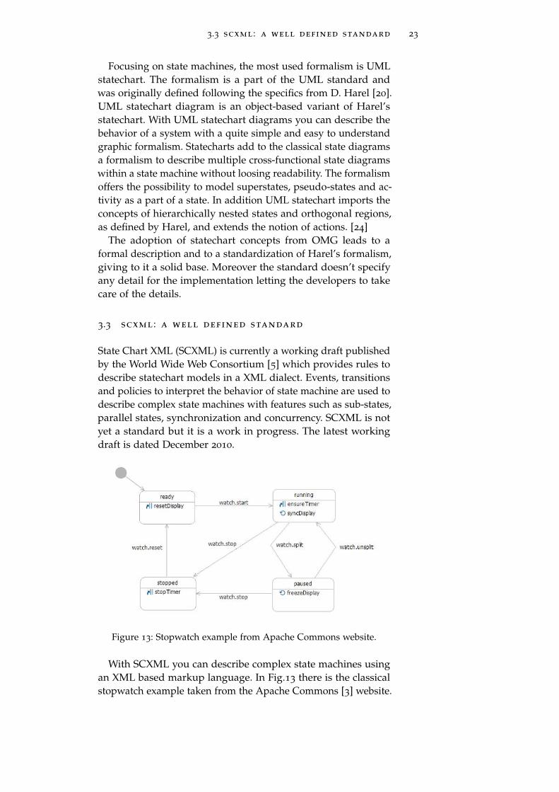
State Chart XML (SCXML) is currently a working draft publishedby the World Wide Web Consortium [5] which provides rules todescribe statechart models in a XML dialect. Events, transitionsand policies to interpret the behavior of state machine are used todescribe complex state machines with features such as sub-states,parallel states, synchronization and concurrency. SCXML is notyet a standard but it is a work in progress. The latest workingdraft is dated December 2010.
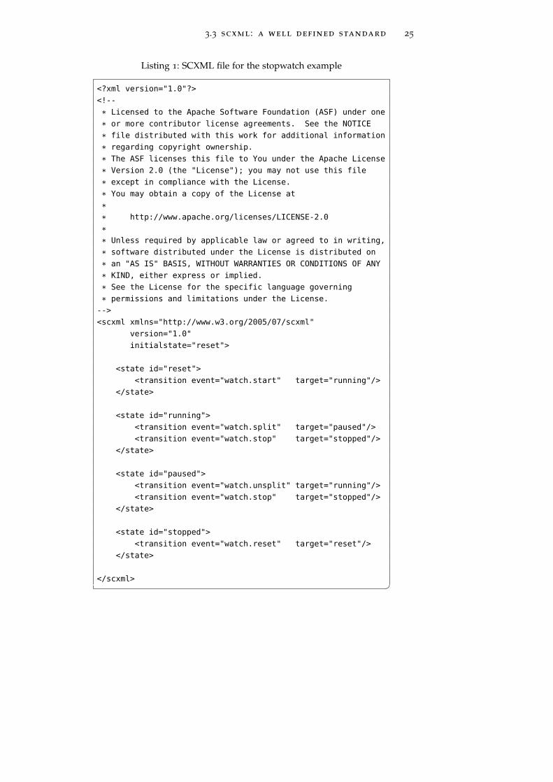
Figure 13: Stopwatch example from Apache Commons website.
With SCXML you can describe complex state machines usingan XML based markup language. In Fig.13 there is the classicalstopwatch example taken from the Apache Commons [3] website.
24 state machines
On the example the structure of the model is easily recognizable:there are states, with a unique name and inside every state thetransitions. Each transition is triggered in response to an event.Following a transition the machine change its state to the targetedone. Models representing simple state machines are easy to readand easy to handle.
SCXML is mostly used in application where there is the needof an interactive dialog between a human and a computer likewith automatic telephone services (voice access to email, callcenter, order inquiry, driving directions etc.). Many workingimplementations are available, most of them based on scriptinglanguages like python. The Apache Foundation offers a pure Javalibrary to parse and execute SCXML diagrams and also the Qtframework makes available a C++ implementation of an SCXMLengine. The Qt framework is also used by Nokia to develop phoneapplications[2].
3.3 scxml : a well defined standard 25
Listing 1: SCXML file for the stopwatch example
<?xml version="1.0"?>
<!--
* Licensed to the Apache Software Foundation (ASF) under one
* or more contributor license agreements. See the NOTICE
* file distributed with this work for additional information
* regarding copyright ownership.
* The ASF licenses this file to You under the Apache License
* Version 2.0 (the "License"); you may not use this file
* except in compliance with the License.
* You may obtain a copy of the License at
*
* http://www.apache.org/licenses/LICENSE-2.0
*
* Unless required by applicable law or agreed to in writing,
* software distributed under the License is distributed on
* an "AS IS" BASIS, WITHOUT WARRANTIES OR CONDITIONS OF ANY
* KIND, either express or implied.
* See the License for the specific language governing
* permissions and limitations under the License.
-->
<scxml xmlns="http://www.w3.org/2005/07/scxml"
version="1.0"
initialstate="reset">
<state id="reset">
<transition event="watch.start" target="running"/>
</state>
<state id="running">
<transition event="watch.split" target="paused"/>
<transition event="watch.stop" target="stopped"/>
</state>
<state id="paused">
<transition event="watch.unsplit" target="running"/>
<transition event="watch.stop" target="stopped"/>
</state>
<state id="stopped">
<transition event="watch.reset" target="reset"/>
</state>
</scxml> �

4U S E D T O O L S
Contents4.1 MagicDraw 284.2 Eclipse 294.3 EMF 30
4.3.1 Generator Workflow Component 31
4.3.2 Xpand 31
4.3.3 Check 32
4.3.4 Xtend 33
4.4 Apache SCXML and the Apache engine 33
Before presenting the used tools, a small summary about thework to be done is needed. The main objective of this work is toproduce code for an application starting from a UML statechartmodel.
The first required tool is a software capable of create and editUML models. During my work I evaluated some options: Mag- From a model to an
applicationicDraw from No Magic Inc., Papyrus from Eclipse Foundation andRational Rose from IBM. I ended to choice MagicDraw mainlyfor two reasons: the first is that the tool can export models inXMI, an interchange format used to transfer the models betweendifferent applications. The second reason is that there is a livelyexchange of views between some developers working at ESOand the team at No Magic. This makes very easy the requestof missing features or to correct wrong implementations in theapplication. Anyhow during my work I checked and verified thecompatibility of my tool also with models exported from otherapplications.
Then I needed a tool to explore and manage models and togenerate the code. Here the choice was quite easy as the EclipseFoundation offers an open software development platform ex-tensible and very flexible. For the same platform a powerfulframework, explicitly designed to handle models, was available.
Finally an engine to run the state machines was required. Afterthe decision to use SCXML to represent models was taken, mainlytwo were the possible options for the engine: the Apache SCXMLengine and the Qt SCXML engine. Again the choice was easy asin the beginning I was working on the ACS platform. Many ofthe application for this platform are developed in Java, C++ orPython. Since the use of the Qt engine would have involved theadoption of big libraries not really needed for other purposes,the adoption of the Apache implementation was straightforward.
27
28 used tools
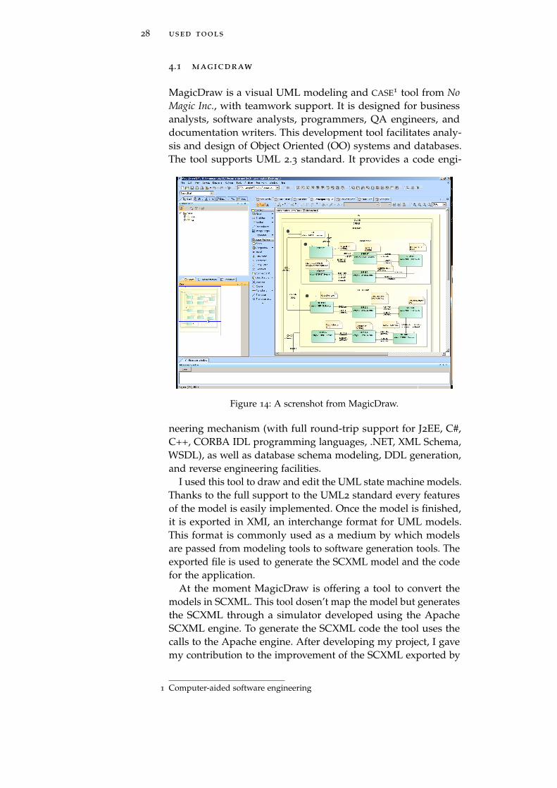
4.1 magicdraw
MagicDraw is a visual UML modeling and CASE1 tool from NoMagic Inc., with teamwork support. It is designed for businessanalysts, software analysts, programmers, QA engineers, anddocumentation writers. This development tool facilitates analy-sis and design of Object Oriented (OO) systems and databases.The tool supports UML 2.3 standard. It provides a code engi-
Figure 14: A screnshot from MagicDraw.
neering mechanism (with full round-trip support for J2EE, C#,C++, CORBA IDL programming languages, .NET, XML Schema,WSDL), as well as database schema modeling, DDL generation,and reverse engineering facilities.
I used this tool to draw and edit the UML state machine models.Thanks to the full support to the UML2 standard every featuresof the model is easily implemented. Once the model is finished,it is exported in XMI, an interchange format for UML models.This format is commonly used as a medium by which modelsare passed from modeling tools to software generation tools. Theexported file is used to generate the SCXML model and the codefor the application.
At the moment MagicDraw is offering a tool to convert themodels in SCXML. This tool dosen’t map the model but generatesthe SCXML through a simulator developed using the ApacheSCXML engine. To generate the SCXML code the tool uses thecalls to the Apache engine. After developing my project, I gavemy contribution to the improvement of the SCXML exported by
1 Computer-aided software engineering
4.2 eclipse 29
MagicDraw, pointing out inaccuracies and error to the No Magicteam.
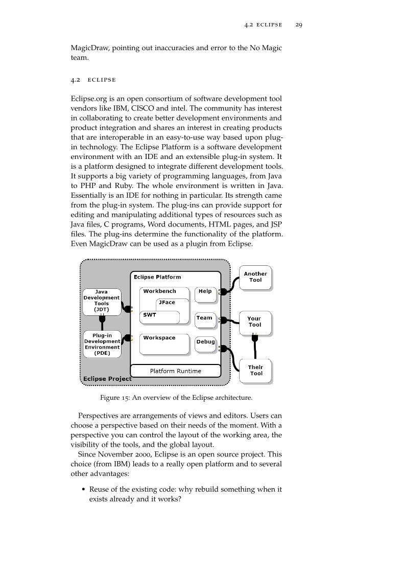
4.2 eclipse
Eclipse.org is an open consortium of software development toolvendors like IBM, CISCO and intel. The community has interestin collaborating to create better development environments andproduct integration and shares an interest in creating productsthat are interoperable in an easy-to-use way based upon plug-in technology. The Eclipse Platform is a software developmentenvironment with an IDE and an extensible plug-in system. Itis a platform designed to integrate different development tools.It supports a big variety of programming languages, from Javato PHP and Ruby. The whole environment is written in Java.Essentially is an IDE for nothing in particular. Its strength camefrom the plug-in system. The plug-ins can provide support forediting and manipulating additional types of resources such asJava files, C programs, Word documents, HTML pages, and JSPfiles. The plug-ins determine the functionality of the platform.Even MagicDraw can be used as a plugin from Eclipse.
Figure 15: An overview of the Eclipse architecture.
Perspectives are arrangements of views and editors. Users canchoose a perspective based on their needs of the moment. With aperspective you can control the layout of the working area, thevisibility of the tools, and the global layout.
Since November 2000, Eclipse is an open source project. Thischoice (from IBM) leads to a really open platform and to severalother advantages:
• Reuse of the existing code: why rebuild something when itexists already and it works?
30 used tools
• Trust: code reuse needs trust on other developers and trustmust be earned by developers providing good code.
• Confidence: providing all the source code of the platformto developers helps on gaining confidence.
• Quality: the code is reviewed by the community, enhancingthe quality through a collaborative approach.
• Clarity: the code is easier to understand as it’s deliveredwith the idea of being reused by the community.
• Longevity: offering the source code to developers the plat-form will ensure long term support.
• Flexibility: the possibility to build your own componentand integrate it in the platform can provide a tailored tool.
In my project I used the Java perspective and the Eclipse Model-ing Framework.
4.3 emf
The Eclipse Modeling Framework is a Java-based environment fordevelopment of tools and other applications based on a structuredmodel. With this framework it’s possible to generate part ofthe code needed to develop applications starting from a model.The repetitive part is done automatically and a skeleton for theapplication is generated. Then a variable amount of hand-writtencode is needed to complete the task.
Almost every piece of software we write interacts with somedata models. These models can be defined using UML, XML, Javaor some other definition language. EMF can be used to extract thisintrinsic model and to generate some of the implementation code.The starting project is based on the OMG’s Meta Object Facility.MOF is an abstract language and a framework for specifying,constructing and managing meta-models. Metamodels can beviewed as models of a model. With metamodeling it’s possibleto describe different domain specific languages with the sameformalism. As the MOF model was very large and complex,with the target of simplifing also the generated code, a drasticredesign of the MOF metamodel led to the Ecore. Ecore is anEcore is a subset of
the MOF metamodel implementation of a subset of the features of MOF. After thissimplification the people at OMG also realized that the MOFmeta model was too complex and, with the contribution of EMFdesigner, they defined MOF 2.0. This redesign led to the EssentialMOF (EMOF) and the Complete MOF (CMOF). Ecore is moreor less aligned with EMOF. The objective of a clean and bettergenerated code was achieved and now the framework is beingused by a large community of developers[26].
4.3 emf 31
The Model to Text Transformation (M2T) is a project built ontop of EMF. With M2T it is possible to transform a model directlyin code for every kind of programming languages. Xpand, Jetand Acceleo are the main project developed within M2T[1].
EMF provides developers with a set of tools to interact withthe Ecore model. M2T offers a leverage to explore and build theapplications straight from the model, transforming each elementin a piece of code.
4.3.1 Generator Workflow Component
The Generator Workflow component is provided to perform thecode generation. The code generation is achieved calling various The workflow file
define the sequenceof the operations
component and running template files. The workflow file definesthe configuration variables and the sequence of the execution.Input and output files are defined here. Also tools to beautify thecode are invoked from the workflow.
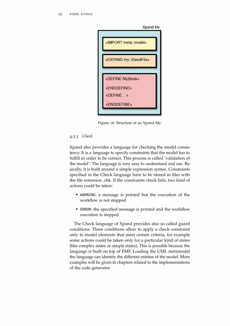
4.3.2 Xpand
Xpand is the language I used from the Model to Text project.This language is specialized on code generation based on EMFmodels. It supports the following main language features:
• Pluggable Type System
• Dynamic Dispatch of Functions
• Aspect Oriented Programming
• Rich Expressions (OCL-like but with Java-like syntax)
This language is used in templates to control the output gen-eration. Templates are stored in files with the extension .xpt. Atemplate file consists of any number of "IMPORT" statements,followed by any number of "EXTENSION" statements, followedby one or more "DEFINE" blocks (called definitions). With the"IMPORT" statement a name space (like UML) is imported, andunqualified name defined in the namespace could be used in-stead of fully qualified names. "EXTENSION" statements is usedto import additional functions and and query operations froman Xtend file. This helps to keep the code clean and easy toread. "DEFINE" blocks qualify a template unit. The body of atemplate can contain a sequence of statements including any textor parameter.
The strength of this language is the modularity.
32 used tools
Figure 16: Structure of an Xpand file.
4.3.3 Check
Xpand also provides a language for checking the model consis-tency. It is a language to specify constraints that the model has tofulfill in order to be correct. This process is called "validation ofthe model". The language is very easy to understand and use. Ba-sically, it is built around a simple expression syntax. Constraintsspecified in the Check language have to be stored in files withthe file extension .chk. If the constraints check fails, two kind ofactions could be taken:
• WARNING: a message is printed but the execution of theworkflow is not stopped
• ERROR: the specified message is printed and the workflowexecution is stopped
The Check language of Xpand provides also so called guardconditions. These conditions allow to apply a check constraintonly to model elements that meet certain criteria, for examplesome actions could be taken only for a particular kind of states(like complex states or simple states). This is possible because thelanguage is built on top of EMF. Loading the UML metamodelthe language can identify the different entities of the model. Moreexamples will be given in chapters related to the implementationsof the code generator.
4.4 apache scxml and the apache engine 33
4.3.4 Xtend
The Xtend language provides the possibility to define rich li-braries of independent operations and non-invasive metamodelextensions based on either Java methods or Xtend expressions.Those libraries can be referenced from all other textual languagesthat are based on the Xpand expressions framework. An Xtendfile must have an .ext extension. Again, the use of these librariesallows to keep the code clean and readable.
4.4 apache scxml and the apache engine
The Apache Foundation is supporting SCXML through the ApacheCommons project. Commons SCXML is a working implementa-tion of a Java SCXML engine capable of executing a state machinedefined in a SCXML document. The latest implementation ofCommons SCXML is v.0.9 and is dated December 2008. Apache Commons
SCXML v.0.10 willbe ready before theend of 2011
Without an engine capable of parsing and executing SCXMLmodels these files would be useless. The Apache foundationand the open source community have developed a java basedexecution environment. The SCXML distribution provides a Javastandalone class to test SCXML models from a command line.The choice of this implementation is dictated by the language.My work started developing an application for ACS and Java isthe most used language on this platform. In addition the Apacheproject is well documented and supported by the community.
I set up the environment following the user guide from theApache website [3] and tested it with the examples provided.From a command line events can be sent and interpreted andalso variables can be set. The interface is rather basic but clearenough for testing purposes.

Part II
D E V E L O P I N G T H E S O L U T I O N

5M O D E L T R A N S F O R M AT I O N
Contents5.1 Problems 375.2 A proposal for UML to SCXML mapping 385.3 Comparison 39
5.3.1 Simple state 39
5.3.2 Initial pseudostate 40
5.3.3 Final pseudostate 41
5.3.4 Entry and exit actions 42
5.3.5 Transition 42
5.3.6 Internal Transition 43
5.3.7 Superstates and substates 44
5.3.8 History pseudostate 45
5.3.9 Activities 46
5.4 Custom actions 475.5 Summary 47
OMG definition of the UML standard is very formal. Every as-pect is addressed in detail. Moving to a working implementationof the standard necessitates modifications and tricks bounded toimplementations details (for example to the used language) or tochoices taken during the early develop phase of the project. If onone side the standard, without any indication on "how" to imple-ment the project, offers a solid starting point, on the other side,is unavoidable to introduce differences. This requires a researchto find these differences (not always well documented). Workingwith something real, and that must work is very different fromformulating principles without having the opportunity to verifyit on the field.
So, the mapping of all these differences is not only a necessity,but should be the fundamental base for the subsequent work.
5.1 problems
In this chapter I present a proposal for the mapping of UML StateMachine to SCXML. It is not a complete mapping but it will focuson the features defined in the Generic State Machine Engine Soft-ware Requirement Specification[12]. This is an internal documentfrom ESO that describes the functions that the GSME shall providein order to build applications based on state machine models forthe ACS or VLTSW platforms.
37

38 model transformation
As the document states, the state machine engine shall sup-port the following state machine features defined by the SCXMLstandard:
• composite states
• orthogonal states
• actions
• invoke (activities)
• guards
• shallow and deep history state
• initial and final pseudo-states
• IsIn
These features first introduced by D. Harel [20] proved to be im-portant when modeling control applications for telescope domain.In particular composite states reduce the number of transitionsand orthogonal states the number of states.
This was the first part of my work done in Garching beiMünchen, home of the headquarters of ESO. The work was thestarting point for the development of the UML2SCXML transfor-mation tool.
5.2 a proposal for uml to scxml mapping
As stated in Chapter 3, UML is a general purpose language thataims to be a standard modeling language. State Chart XML [3]is a formal description on how to translate an UML statechartin a XML dialect. The execution environment provided from theApache Foundation is a Java SCXML engine capable of executinga state machine defined in a SCXML document.
Working to develop a tool to translate a UML state machinemodel to a SCXML document brought to my attention somedifferences between the specifications, mainly due to the continu-ous changes in the standards and in the working draft, that arenot always quickly implemented in the Apache engine. In addi-tion the distance between the release date of the implementationand the latest working draft increases the number of differences.When the working draft from W3C will be ready to become astandard an update of the engine from the Apache Foundationwill probably smooth all these details.
5.3 comparison 39
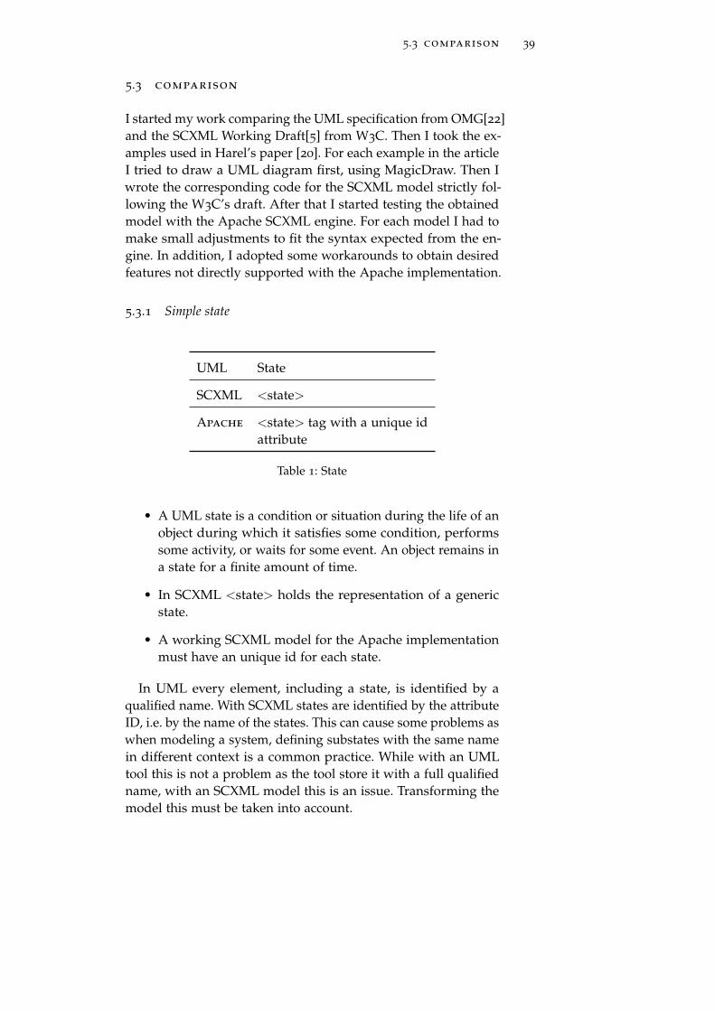
5.3 comparison
I started my work comparing the UML specification from OMG[22]and the SCXML Working Draft[5] from W3C. Then I took the ex-amples used in Harel’s paper [20]. For each example in the articleI tried to draw a UML diagram first, using MagicDraw. Then Iwrote the corresponding code for the SCXML model strictly fol-lowing the W3C’s draft. After that I started testing the obtainedmodel with the Apache SCXML engine. For each model I had tomake small adjustments to fit the syntax expected from the en-gine. In addition, I adopted some workarounds to obtain desiredfeatures not directly supported with the Apache implementation.
5.3.1 Simple state
UML State
SCXML <state>
Apache <state> tag with a unique idattribute
Table 1: State
• A UML state is a condition or situation during the life of anobject during which it satisfies some condition, performssome activity, or waits for some event. An object remains ina state for a finite amount of time.
• In SCXML <state> holds the representation of a genericstate.
• A working SCXML model for the Apache implementationmust have an unique id for each state.
In UML every element, including a state, is identified by aqualified name. With SCXML states are identified by the attributeID, i.e. by the name of the states. This can cause some problems aswhen modeling a system, defining substates with the same namein different context is a common practice. While with an UMLtool this is not a problem as the tool store it with a full qualifiedname, with an SCXML model this is an issue. Transforming themodel this must be taken into account.
40 model transformation
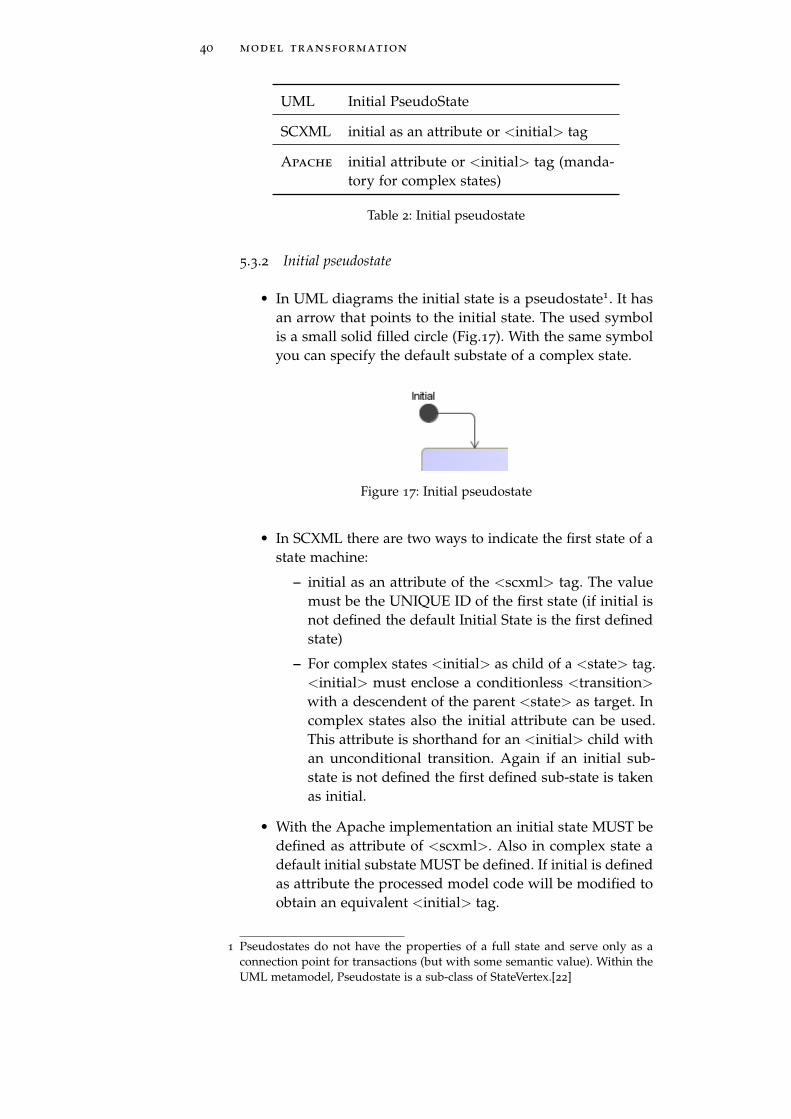
UML Initial PseudoState
SCXML initial as an attribute or <initial> tag
Apache initial attribute or <initial> tag (manda-tory for complex states)
Table 2: Initial pseudostate
5.3.2 Initial pseudostate
• In UML diagrams the initial state is a pseudostate1. It hasan arrow that points to the initial state. The used symbolis a small solid filled circle (Fig.17). With the same symbolyou can specify the default substate of a complex state.
Figure 17: Initial pseudostate
• In SCXML there are two ways to indicate the first state of astate machine:
– initial as an attribute of the <scxml> tag. The valuemust be the UNIQUE ID of the first state (if initial isnot defined the default Initial State is the first definedstate)
– For complex states <initial> as child of a <state> tag.<initial> must enclose a conditionless <transition>with a descendent of the parent <state> as target. Incomplex states also the initial attribute can be used.This attribute is shorthand for an <initial> child withan unconditional transition. Again if an initial sub-state is not defined the first defined sub-state is takenas initial.
• With the Apache implementation an initial state MUST bedefined as attribute of <scxml>. Also in complex state adefault initial substate MUST be defined. If initial is definedas attribute the processed model code will be modified toobtain an equivalent <initial> tag.
1 Pseudostates do not have the properties of a full state and serve only as aconnection point for transactions (but with some semantic value). Within theUML metamodel, Pseudostate is a sub-class of StateVertex.[22]
5.3 comparison 41
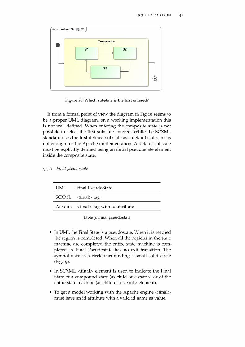
Figure 18: Which substate is the first entered?
If from a formal point of view the diagram in Fig.18 seems tobe a proper UML diagram, on a working implementation thisis not well defined. When entering the composite state is notpossible to select the first substate entered. While the SCXMLstandard uses the first defined substate as a default state, this isnot enough for the Apache implementation. A default substatemust be explicitly defined using an initial pseudostate elementinside the composite state.
5.3.3 Final pseudostate
UML Final PseudoState
SCXML <final> tag
Apache <final> tag with id attribute
Table 3: Final pseudostate
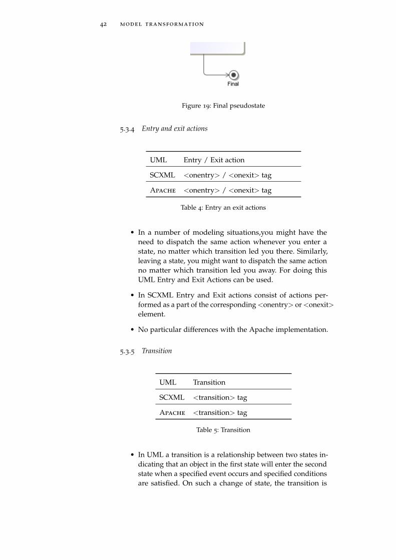
• In UML the Final State is a pseudostate. When it is reachedthe region is completed. When all the regions in the statemachine are completed the entire state machine is com-pleted. A Final Pseudostate has no exit transition. Thesymbol used is a circle surrounding a small solid circle(Fig.19).
• In SCXML <final> element is used to indicate the FinalState of a compound state (as child of <state>) or of theentire state machine (as child of <scxml> element).
• To get a model working with the Apache engine <final>must have an id attribute with a valid id name as value.
42 model transformation
Figure 19: Final pseudostate
5.3.4 Entry and exit actions
UML Entry / Exit action
SCXML <onentry> / <onexit> tag
Apache <onentry> / <onexit> tag
Table 4: Entry an exit actions
• In a number of modeling situations,you might have theneed to dispatch the same action whenever you enter astate, no matter which transition led you there. Similarly,leaving a state, you might want to dispatch the same actionno matter which transition led you away. For doing thisUML Entry and Exit Actions can be used.
• In SCXML Entry and Exit actions consist of actions per-formed as a part of the corresponding <onentry> or <onexit>element.
• No particular differences with the Apache implementation.
5.3.5 Transition
UML Transition
SCXML <transition> tag
Apache <transition> tag
Table 5: Transition
• In UML a transition is a relationship between two states in-dicating that an object in the first state will enter the secondstate when a specified event occurs and specified conditionsare satisfied. On such a change of state, the transition is
5.3 comparison 43
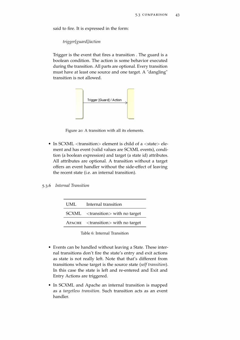
said to fire. It is expressed in the form:
trigger[guard]/action
Trigger is the event that fires a transition . The guard is aboolean condition. The action is some behavior executedduring the transition. All parts are optional. Every transitionmust have at least one source and one target. A "dangling"transition is not allowed.
Figure 20: A transition with all its elements.
• In SCXML <transition> element is child of a <state> ele-ment and has event (valid values are SCXML events), condi-tion (a boolean expression) and target (a state id) attributes.All attributes are optional. A transition without a targetoffers an event handler without the side-effect of leavingthe recent state (i.e. an internal transition).
5.3.6 Internal Transition
UML Internal transition
SCXML <transition> with no target
Apache <transition> with no target
Table 6: Internal Transition
• Events can be handled without leaving a State. These inter-nal transitions don’t fire the state’s entry and exit actionsas state is not really left. Note that that’s different fromtransitions whose target is the source state (self transition).In this case the state is left and re-entered and Exit andEntry Actions are triggered.
• In SCXML and Apache an internal transition is mappedas a targetless transition. Such transition acts as an eventhandler.
44 model transformation
5.3.7 Superstates and substates
UML Superstate
SCXML <state> or <parallel> a default substatemust be defined
Apache <state> or <parallel>
Table 7: Superstates
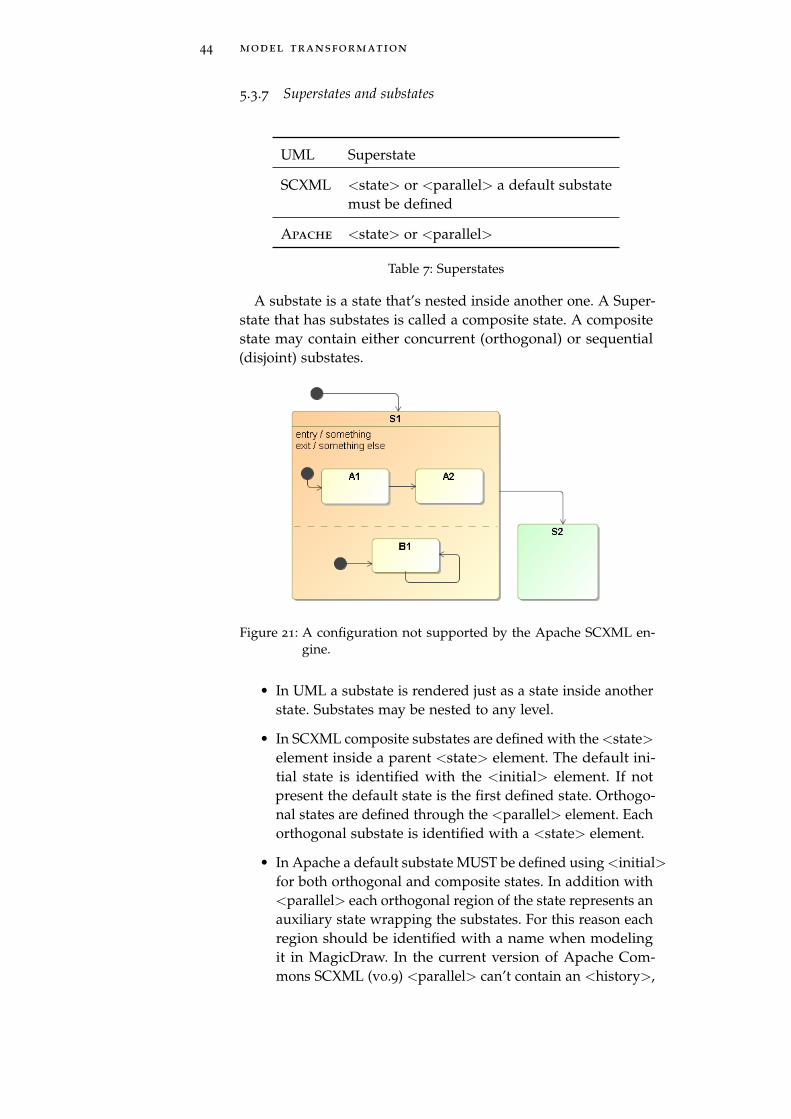
A substate is a state that’s nested inside another one. A Super-state that has substates is called a composite state. A compositestate may contain either concurrent (orthogonal) or sequential(disjoint) substates.
Figure 21: A configuration not supported by the Apache SCXML en-gine.
• In UML a substate is rendered just as a state inside anotherstate. Substates may be nested to any level.
• In SCXML composite substates are defined with the <state>element inside a parent <state> element. The default ini-tial state is identified with the <initial> element. If notpresent the default state is the first defined state. Orthogo-nal states are defined through the <parallel> element. Eachorthogonal substate is identified with a <state> element.
• In Apache a default substate MUST be defined using <initial>for both orthogonal and composite states. In addition with<parallel> each orthogonal region of the state represents anauxiliary state wrapping the substates. For this reason eachregion should be identified with a name when modelingit in MagicDraw. In the current version of Apache Com-mons SCXML (v0.9) <parallel> can’t contain an <history>,
5.3 comparison 45
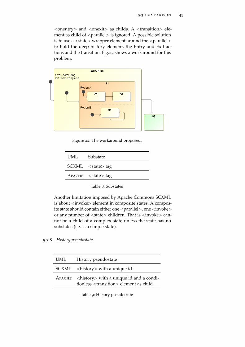
<onentry> and <onexit> as childs. A <transition> ele-ment as child of <parallel> is ignored. A possible solutionis to use a <state> wrapper element around the <parallel>to hold the deep history element, the Entry and Exit ac-tions and the transition. Fig.22 shows a workaround for thisproblem.
Figure 22: The workaround proposed.
UML Substate
SCXML <state> tag
Apache <state> tag
Table 8: Substates
Another limitation imposed by Apache Commons SCXMLis about <invoke> element in composite states. A compos-ite state should contain either one <parallel>, one <invoke>or any number of <state> children. That is <invoke> can-not be a child of a complex state unless the state has nosubstates (i.e. is a simple state).
5.3.8 History pseudostate
UML History pseudostate
SCXML <history> with a unique id
Apache <history> with a unique id and a condi-tionless <transition> element as child
Table 9: History pseudostate
46 model transformation
• In UML diagrams a history pseudostate can rememberthe last active configuration of the object before leaving acomposite state. There are two kind of history:
– Shallow history can remember only the history of theimmediate nested states
– Deep history can remember the configurations of allthe nested states, at any depth.
A default state must be defined, to enter when there is nohistory for the state.
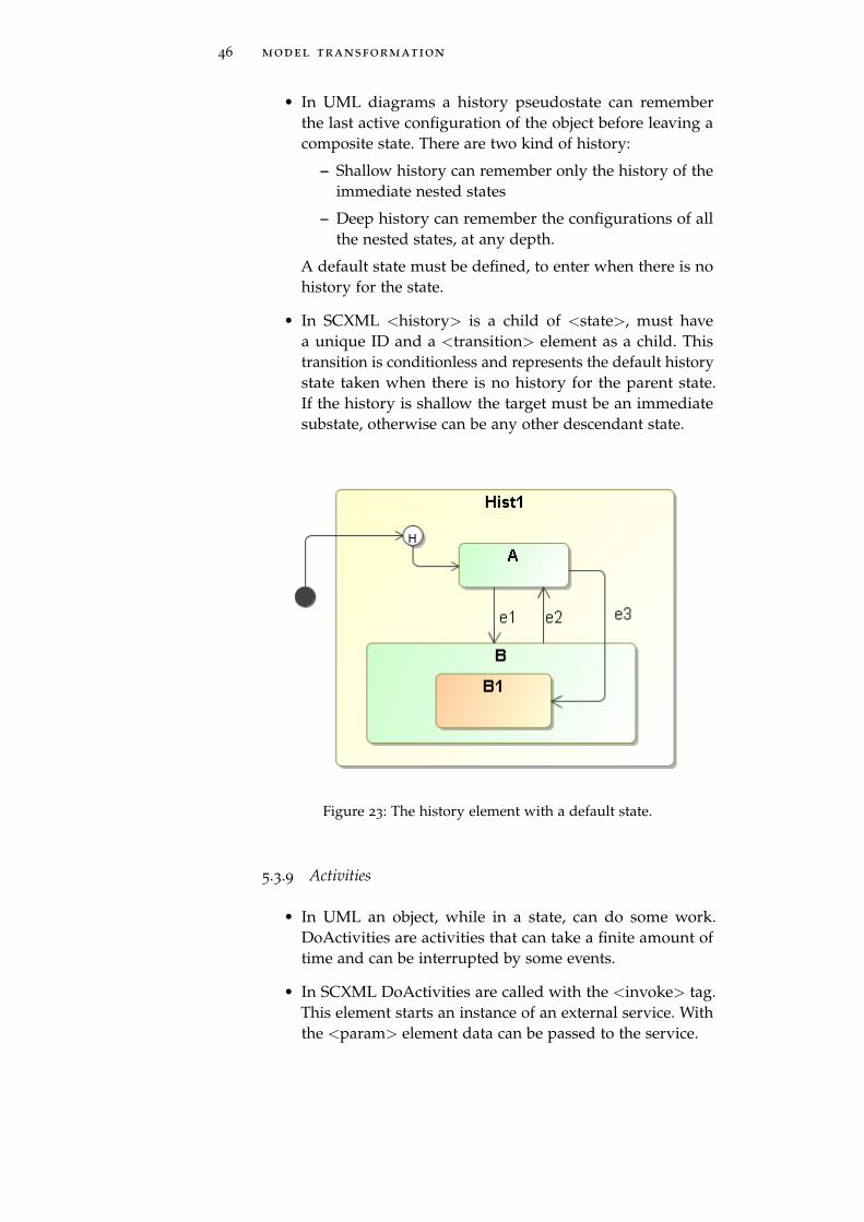
• In SCXML <history> is a child of <state>, must havea unique ID and a <transition> element as a child. Thistransition is conditionless and represents the default historystate taken when there is no history for the parent state.If the history is shallow the target must be an immediatesubstate, otherwise can be any other descendant state.
Figure 23: The history element with a default state.
5.3.9 Activities
• In UML an object, while in a state, can do some work.DoActivities are activities that can take a finite amount oftime and can be interrupted by some events.
• In SCXML DoActivities are called with the <invoke> tag.This element starts an instance of an external service. Withthe <param> element data can be passed to the service.
5.4 custom actions 47
UML Activities
SCXML <invoke> tag
Apache <invoke> tag
Table 10: Activities
• Also the Apache engine can handle DoActivities via the<invoke> element. An external state machine can be firedand the developer can let this external element deal withdifferent implementations of activities. This allow to modela concurrent execution of the external service.
5.4 custom actions
The execution of an action represents some transformation orprocessing in the modeled system. As we saw in section 3.1an action is supposed to be instantaneous. If there is the needto model some more complex behaviors, that require time tocompleted, a new state must be modeled. Inside the state aDoActivity will be used.
The SCXML specification describes a basic set of commandimplementing actions, useful for logging purposes or very sim-ple executions. In many cases, this is not enough. The Apacheimplementation, as defined in the SCXML working draft, allowsto define and use Custom actions. These are used to execute aspecific implementation of arbitrary commands or code definedby the developer.
To transform this kind of actions and to generate a workingSCXML model, first a fictitious namespace is needed (I used"http://my.custom-actions.domain/CUSTOM"). Then the custom tag,named with the same name of the custom action, is created inthe proper context.
5.5 summary
Translating a model defined with UML statechart to an Apacheworking SCXML model is not trivial. The developer must be care-ful with small implementation details and in some cases specialworkarounds must be taken. The Apache SCXML engine provide The mapping process
is essential: there aremany differencesbetween thestandards
an execution environment that can support all the features de-fined in the GSME Software Requirements Specification[12]. Withthis mapping proposal these features are interpreted correctly. Itwas very interesting to see how things change from the standardto a real and working implementation of the engine. Most of the

48 model transformation
problems are due to the latest modifications of the working draftand to the old implementation of the Apache engine. In addition,the fact that the W3C specifications are still in the form of a work-ing draft keeps away the developers from investing too muchtime in making changes that may be not definitive. Certainlywhen the working draft will take the form of a recommenda-tion a new impulse will hit also the development process of theApache engine. Hopefully this will smooth a lot of differencesand make easier the adoption of this interesting framework.
6T H E C O D E G E N E R AT O R
Contents6.1 The Generic State Machine Engine Architec-
ture 496.1.1 Model Independent State Machine
Engine 50
6.2 Implementation 526.2.1 Designing a model with MagicDraw 52
6.2.2 Transforming the model 53
6.2.3 Check 56
6.2.4 Xpand 58
6.2.5 Xtend 61
6.3 A running example: MasterComponent 636.3.1 Available substates 64
6.3.2 Substates of Online and Operational 65
6.3.3 A few modifications 65
6.3.4 The generated files 66
6.1 the generic state machine engine architecture
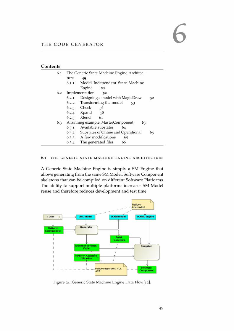
A Generic State Machine Engine is simply a SM Engine thatallows generating from the same SM Model, Software Componentskeletons that can be compiled on different Software Platforms.The ability to support multiple platforms increases SM Modelreuse and therefore reduces development and test time.
Figure 24: Generic State Machine Engine Data Flow[12].
49
50 the code generator
The main goal of the Generic State Machine Engine project isto develop a tool that can facilitate the creation of state machinebased Software Components for the VLT and ACS Software Plat-forms. The architecture is built on top of a Java SCXML Enginewhich executes SCXML Models. In the next future also a C++ im-plementation of the engine is planned. A Generator takes as inputthe configuration on the target platform (Platform Configuration)and the UML Model to generate: all the Model Dependent Code,the Build Procedure (for example the Makefile) and the SCXMLModel. Examples of Model Dependent Code are: the code topropagate the events to the SCXML Engine, Actions, Guards, andActivities skeletons. Platform Adapters Libraries, used to providea standard interface for services like logging, error handling, mes-saging etc. (i.e. to abstract the Software Platform specific services),are compiled together with the SCXML Engine, and the ModelDependent Code to build the Software Component.
6.1.1 Model Independent State Machine Engine
A State Machine Engine is an executable implementation of aState Machine Model. State Machine Engines can be developedusing different approaches: from the simple "switch" statements,or the State Design Pattern1, up to building an interpreter of StateMachine Models. In [12] the definitions of "Model IndependentState Machine Engine" and "Model Dependent State MachineEngine" have been introduced to classify two different types ofState Machine Engines: the ones whose implementation does notchange when a different State Machine Model is executed andthe ones whose implementation does change.
In a Model Dependent SM Engine the model (states, transitions,etc.) is hard coded in the implementation language and thereforedefined at compile-time. Examples are:
• SM Engine based on "switch" statements
• SM Engine based on State Pattern
Disadvantages of this approach are:
• SM model must be defined at compile-time
• The size of the application is usually larger since it includesthe logic of the SM
1 From [17]: the state pattern is a behavioral software design pattern, also knownas the objects for states pattern. This pattern is used in computer programmingto represent the state of an object. This is a clean way for an object to partiallychange its type at runtime

6.1 the generic state machine engine architecture 51
• SM Model and source code may easily get out-of-synch ifthe code is not generated from the model every time it iscompiled
Advantages of this approach are:
• Performances and memory consumption can be optimized(since the State Machine Engine is build specifically for thatgiven model)
• There is no need of the model once the application is built(or generated). In many cases the model can be recon-structed from the application if/when needed.
In a Model Independent SM Engine the model is stored inmemory. The SM Engine provides APIs to create states, transi-tions, etc and build up an in-memory representation of the model.The algorithm works with the in-memory representation of themodel to decide which transitions to take, which states to visit,which actions to execute.
Disadvantages of this approach:
• Performances and memory consumptions may not be asgood as the one of Model Dependent SM Engines
• The model is needed for the execution of the application
• No type-safe invocation of actions/activities
Advantages of this approach:
• SM Engine can be reused by the applications
– Applications are smaller
– Similar advantages of the libraries
• SM Model can be defined at:
– Compile-time using the APIs provided by the SM En-gine to build up the SM model. Development of ac-tions, data, events is done using a compiled program-ming language.
– Run-time using a parser which reads a SM Model Rep-resentation and calls the SM Engine APIs to instantiatethe model. Note that in a fully Run-time SM Enginealso data, actions and events are defined in the modeland interpreted (i.e. the action language is interpreted).This approach provides the flexibility of changing atruntime the complete behavior of the application with-out the need of recompiling the application.
52 the code generator
– Partially at compile time and partially at run-time:data, actions and events are defined at compile timewhile states and transitions are loaded and interpretedat run-time.
The decision of selecting which approach is the best is similarto evaluating the advantages and disadvantages of interpretedvs. compiled programming languages. The mix case, where ac-tions and data are compiled while the state machine logic (statesand transitions) are interpreted, is an interesting alternative thatminimizes the disadvantages of the compiled programming lan-guages and introduces some of the advantages of the interpretedlanguages: there is no need to recompile if the SM logic changes.Recompilation is needed only if data/actions change which couldbe a positive effect since it forces the type checking.
The ability of quickly modifying the application behavior (i.e.the SM logic) without the need for recompiling the code be-comes an important feature in all the scenarios where last minutechanges in the requirements have to be quickly implemented andtested. The need of a Model Independent SM Engine is one of thelessons learned in the development of previous projects at ESO
6.2 implementation
To develop the code generator, as stated in the first part of thisdocument, I used:
• MagicDraw to draw and export UML models (some testswere made also with Papyrus, a UML design tool now partof the eclipse software)
• Eclipse and the Eclipse Modeling Framework to load andmanage models
• XTEND, XPAND and CHECK languages, available on topof EMF, useful to browse and analyze XMI models and togenerate the code.
• Apache Commons SCXML Standalone Engine, a java classto test models
Here will follow a description of the whole process, fromcreating a model with MagicDraw to the testing with the Apacheengine.
6.2.1 Designing a model with MagicDraw
First of all a UML state machine diagram is needed. With Magic-Draw it’s easy to draw this kind of diagram from scratch. I made
6.2 implementation 53
this list of properties while comparing the specifications of thestandards with the Apache implementation of the SCXML engine.In a state machine diagram:
• a state machines must have a name
• a state machines must have inner states
• a state machine must have an initial state
• every state must have a name
• if present, a final state must have a name
• in composite state, a default state is needed
• in orthogonal states, every region must have a name
To work with the current version of the Apache engine someother rules must be respected:
• Entry actions are not allowed in orthogonal states
• Exit actions are not allowed in orthogonal states
• Transitions from orthogonal states are ignored
These limitations are only due to the current implementation ofthe engine (v.0.9) and may change with a new version.
In any case my tool will check the models and see if theyfulfill these rules. Following these few guidelines a state machinediagrams can be exported in Ecore, a format that can be handledwith eclipse. To do this, save the diagram and from the File menuselect Export To -> Eclipse UML (v2.x) XMI File.
6.2.2 Transforming the model
On the activity diagram of Fig.25 are defined the steps the codegenerator will do to produce the application. The transformationtool will be initialized with the platform configuration details.The UML metamodel is loaded and the tool takes as input anecore model (or a MagicDraw model exported as XMI for Eclipse).It will explore it, checking for constraints as specified in the Checkfile called constraints.chk. If the model checking is ok, the output The file
constraints.chkcontains all theconstraints Idiscovered anddescribed in themapping phase
directory is cleaned and the transformation will start. An XMLfile will be created for every state machine in the model. TheseXML are the SCXML models of the state machines. These files gothrough the beautifiers and the final output files are generated.
The expand file FSMScxml.xpt defines how the model is ex-plored.
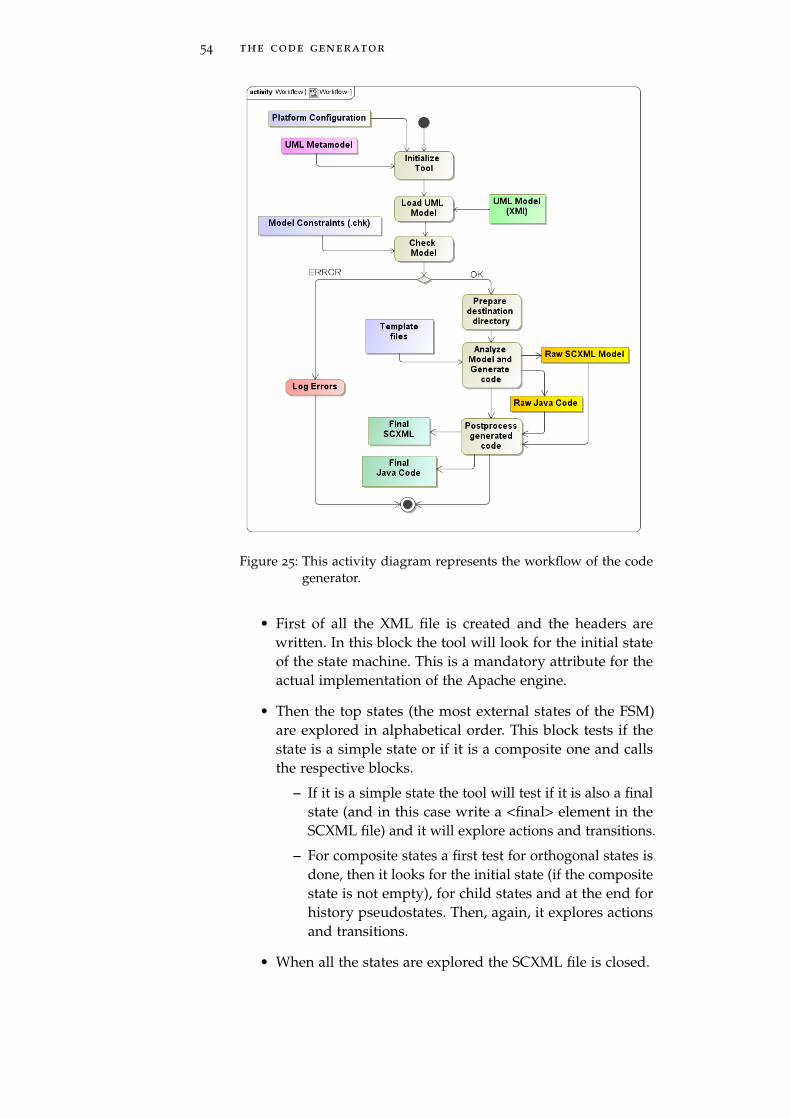
54 the code generator
Figure 25: This activity diagram represents the workflow of the codegenerator.
• First of all the XML file is created and the headers arewritten. In this block the tool will look for the initial stateof the state machine. This is a mandatory attribute for theactual implementation of the Apache engine.
• Then the top states (the most external states of the FSM)are explored in alphabetical order. This block tests if thestate is a simple state or if it is a composite one and callsthe respective blocks.
– If it is a simple state the tool will test if it is also a finalstate (and in this case write a <final> element in theSCXML file) and it will explore actions and transitions.
– For composite states a first test for orthogonal states isdone, then it looks for the initial state (if the compositestate is not empty), for child states and at the end forhistory pseudostates. Then, again, it explores actionsand transitions.
• When all the states are explored the SCXML file is closed.
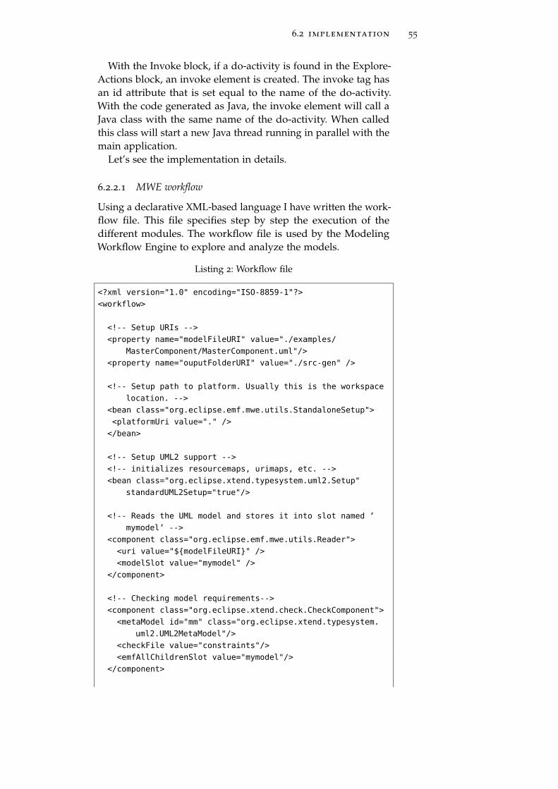
6.2 implementation 55
With the Invoke block, if a do-activity is found in the Explore-Actions block, an invoke element is created. The invoke tag hasan id attribute that is set equal to the name of the do-activity.With the code generated as Java, the invoke element will call aJava class with the same name of the do-activity. When calledthis class will start a new Java thread running in parallel with themain application.
Let’s see the implementation in details.
6.2.2.1 MWE workflow
Using a declarative XML-based language I have written the work-flow file. This file specifies step by step the execution of thedifferent modules. The workflow file is used by the ModelingWorkflow Engine to explore and analyze the models.
Listing 2: Workflow file
<?xml version="1.0" encoding="ISO-8859-1"?>
<workflow>
<!-- Setup URIs -->
<property name="modelFileURI" value="./examples/
MasterComponent/MasterComponent.uml"/>
<property name="ouputFolderURI" value="./src-gen" />
<!-- Setup path to platform. Usually this is the workspace
location. -->
<bean class="org.eclipse.emf.mwe.utils.StandaloneSetup">
<platformUri value="." />
</bean>
<!-- Setup UML2 support -->
<!-- initializes resourcemaps, urimaps, etc. -->
<bean class="org.eclipse.xtend.typesystem.uml2.Setup"
standardUML2Setup="true"/>
<!-- Reads the UML model and stores it into slot named ’
mymodel’ -->
<component class="org.eclipse.emf.mwe.utils.Reader">
<uri value="${modelFileURI}" />
<modelSlot value="mymodel" />
</component>
<!-- Checking model requirements-->
<component class="org.eclipse.xtend.check.CheckComponent">
<metaModel id="mm" class="org.eclipse.xtend.typesystem.
uml2.UML2MetaModel"/>
<checkFile value="constraints"/>
<emfAllChildrenSlot value="mymodel"/>
</component>
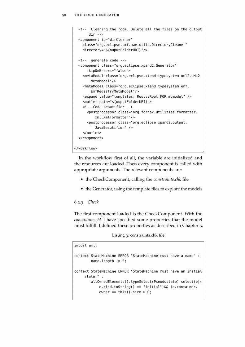
56 the code generator
<!-- Cleaning the room. Delete all the files on the output
dir -->
<component id="dirCleaner"
class="org.eclipse.emf.mwe.utils.DirectoryCleaner"
directory="${ouputFolderURI}"/>
<!-- generate code -->
<component class="org.eclipse.xpand2.Generator"
skipOnErrors="false">
<metaModel class="org.eclipse.xtend.typesystem.uml2.UML2
MetaModel"/>
<metaModel class="org.eclipse.xtend.typesystem.emf.
EmfRegistryMetaModel"/>
<expand value="templates::Root::Root FOR mymodel" />
<outlet path="${ouputFolderURI}">
<!-- Code beautifier -->
<postprocessor class="org.fornax.utilities.formatter.
xml.XmlFormatter"/>
<postprocessor class="org.eclipse.xpand2.output.
JavaBeautifier" />
</outlet>
</component>
</workflow> �In the workflow first of all, the variable are initialized and
the resources are loaded. Then every component is called withappropriate arguments. The relevant components are:
• the CheckComponent, calling the constraints.chk file
• the Generator, using the template files to explore the models
6.2.3 Check
The first component loaded is the CheckComponent. With theconstraints.chk I have specified some properties that the modelmust fulfill. I defined these properties as described in Chapter 5.
Listing 3: constraints.chk file
import uml;
context StateMachine ERROR "StateMachine must have a name" :
name.length != 0;
context StateMachine ERROR "StateMachine must have an initial
state." :
allOwnedElements().typeSelect(Pseudostate).select(e|(
e.kind.toString() == "initial")&& (e.container.
owner == this)).size > 0;
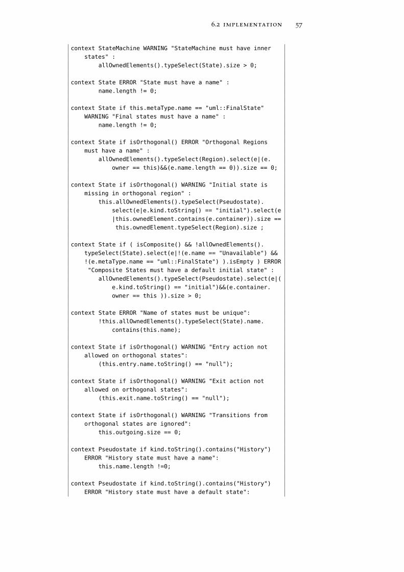
6.2 implementation 57
context StateMachine WARNING "StateMachine must have inner
states" :
allOwnedElements().typeSelect(State).size > 0;
context State ERROR "State must have a name" :
name.length != 0;
context State if this.metaType.name == "uml::FinalState"
WARNING "Final states must have a name" :
name.length != 0;
context State if isOrthogonal() ERROR "Orthogonal Regions
must have a name" :
allOwnedElements().typeSelect(Region).select(e|(e.
owner == this)&&(e.name.length == 0)).size == 0;
context State if isOrthogonal() WARNING "Initial state is
missing in orthogonal region" :
this.allOwnedElements().typeSelect(Pseudostate).
select(e|e.kind.toString() == "initial").select(e
|this.ownedElement.contains(e.container)).size ==
this.ownedElement.typeSelect(Region).size ;
context State if ( isComposite() && !allOwnedElements().
typeSelect(State).select(e|!(e.name == "Unavailable") &&
!(e.metaType.name == "uml::FinalState") ).isEmpty ) ERROR
"Composite States must have a default initial state" :
allOwnedElements().typeSelect(Pseudostate).select(e|(
e.kind.toString() == "initial")&&(e.container.
owner == this )).size > 0;
context State ERROR "Name of states must be unique":
!this.allOwnedElements().typeSelect(State).name.
contains(this.name);
context State if isOrthogonal() WARNING "Entry action not
allowed on orthogonal states":
(this.entry.name.toString() == "null");
context State if isOrthogonal() WARNING "Exit action not
allowed on orthogonal states":
(this.exit.name.toString() == "null");
context State if isOrthogonal() WARNING "Transitions from
orthogonal states are ignored":
this.outgoing.size == 0;
context Pseudostate if kind.toString().contains("History")
ERROR "History state must have a name":
this.name.length !=0;
context Pseudostate if kind.toString().contains("History")
ERROR "History state must have a default state":
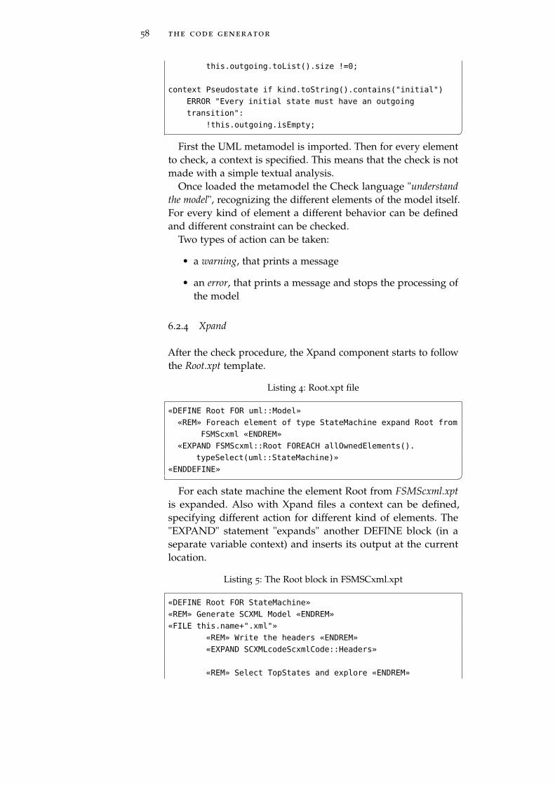
58 the code generator
this.outgoing.toList().size !=0;
context Pseudostate if kind.toString().contains("initial")
ERROR "Every initial state must have an outgoing
transition":
!this.outgoing.isEmpty; �First the UML metamodel is imported. Then for every element
to check, a context is specified. This means that the check is notmade with a simple textual analysis.
Once loaded the metamodel the Check language "understandthe model", recognizing the different elements of the model itself.For every kind of element a different behavior can be definedand different constraint can be checked.
Two types of action can be taken:
• a warning, that prints a message
• an error, that prints a message and stops the processing ofthe model
6.2.4 Xpand
After the check procedure, the Xpand component starts to followthe Root.xpt template.
Listing 4: Root.xpt file
«DEFINE Root FOR uml::Model»
«REM» Foreach element of type StateMachine expand Root from
FSMScxml «ENDREM»
«EXPAND FSMScxml::Root FOREACH allOwnedElements().
typeSelect(uml::StateMachine)»
«ENDDEFINE» �For each state machine the element Root from FSMScxml.xpt
is expanded. Also with Xpand files a context can be defined,specifying different action for different kind of elements. The"EXPAND" statement "expands" another DEFINE block (in aseparate variable context) and inserts its output at the currentlocation.
Listing 5: The Root block in FSMSCxml.xpt
«DEFINE Root FOR StateMachine»
«REM» Generate SCXML Model «ENDREM»
«FILE this.name+".xml"»
«REM» Write the headers «ENDREM»
«EXPAND SCXMLcodeScxmlCode::Headers»
«REM» Select TopStates and explore «ENDREM»
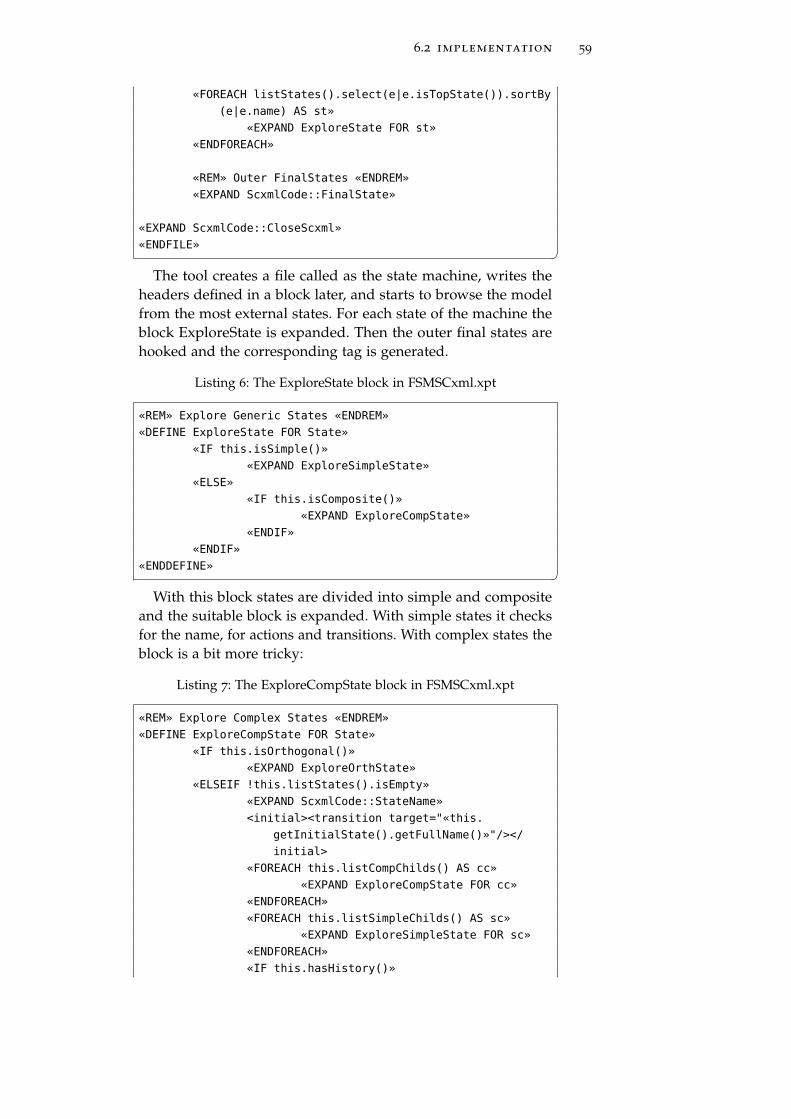
6.2 implementation 59
«FOREACH listStates().select(e|e.isTopState()).sortBy
(e|e.name) AS st»
«EXPAND ExploreState FOR st»
«ENDFOREACH»
«REM» Outer FinalStates «ENDREM»
«EXPAND ScxmlCode::FinalState»
«EXPAND ScxmlCode::CloseScxml»
«ENDFILE» �The tool creates a file called as the state machine, writes the
headers defined in a block later, and starts to browse the modelfrom the most external states. For each state of the machine theblock ExploreState is expanded. Then the outer final states arehooked and the corresponding tag is generated.
Listing 6: The ExploreState block in FSMSCxml.xpt
«REM» Explore Generic States «ENDREM»
«DEFINE ExploreState FOR State»
«IF this.isSimple()»
«EXPAND ExploreSimpleState»
«ELSE»
«IF this.isComposite()»
«EXPAND ExploreCompState»
«ENDIF»
«ENDIF»
«ENDDEFINE» �With this block states are divided into simple and composite
and the suitable block is expanded. With simple states it checksfor the name, for actions and transitions. With complex states theblock is a bit more tricky:
Listing 7: The ExploreCompState block in FSMSCxml.xpt
«REM» Explore Complex States «ENDREM»
«DEFINE ExploreCompState FOR State»
«IF this.isOrthogonal()»
«EXPAND ExploreOrthState»
«ELSEIF !this.listStates().isEmpty»
«EXPAND ScxmlCode::StateName»
<initial><transition target="«this.
getInitialState().getFullName()»"/></
initial>
«FOREACH this.listCompChilds() AS cc»
«EXPAND ExploreCompState FOR cc»
«ENDFOREACH»
«FOREACH this.listSimpleChilds() AS sc»
«EXPAND ExploreSimpleState FOR sc»
«ENDFOREACH»
«IF this.hasHistory()»
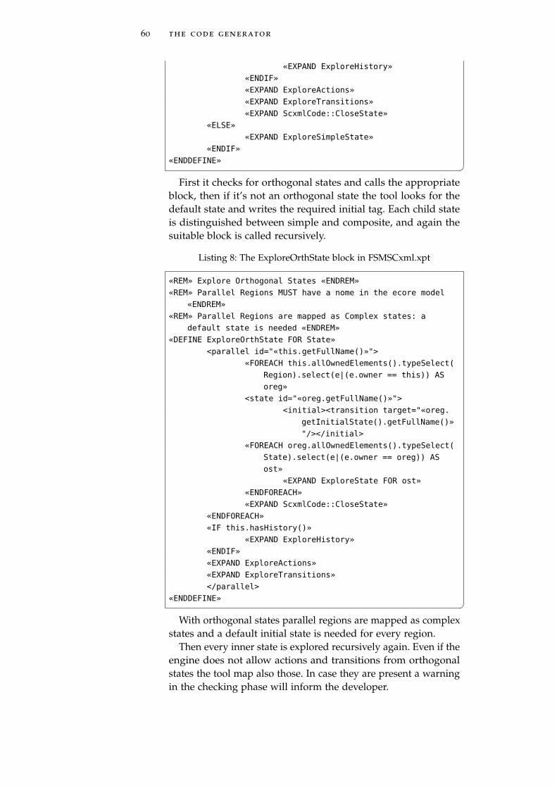
60 the code generator
«EXPAND ExploreHistory»
«ENDIF»
«EXPAND ExploreActions»
«EXPAND ExploreTransitions»
«EXPAND ScxmlCode::CloseState»
«ELSE»
«EXPAND ExploreSimpleState»
«ENDIF»
«ENDDEFINE» �First it checks for orthogonal states and calls the appropriate
block, then if it’s not an orthogonal state the tool looks for thedefault state and writes the required initial tag. Each child stateis distinguished between simple and composite, and again thesuitable block is called recursively.
Listing 8: The ExploreOrthState block in FSMSCxml.xpt
«REM» Explore Orthogonal States «ENDREM»
«REM» Parallel Regions MUST have a nome in the ecore model
«ENDREM»
«REM» Parallel Regions are mapped as Complex states: a
default state is needed «ENDREM»
«DEFINE ExploreOrthState FOR State»
<parallel id="«this.getFullName()»">
«FOREACH this.allOwnedElements().typeSelect(
Region).select(e|(e.owner == this)) AS
oreg»
<state id="«oreg.getFullName()»">
<initial><transition target="«oreg.
getInitialState().getFullName()»
"/></initial>
«FOREACH oreg.allOwnedElements().typeSelect(
State).select(e|(e.owner == oreg)) AS
ost»
«EXPAND ExploreState FOR ost»
«ENDFOREACH»
«EXPAND ScxmlCode::CloseState»
«ENDFOREACH»
«IF this.hasHistory()»
«EXPAND ExploreHistory»
«ENDIF»
«EXPAND ExploreActions»
«EXPAND ExploreTransitions»
</parallel>
«ENDDEFINE» �With orthogonal states parallel regions are mapped as complex
states and a default initial state is needed for every region.Then every inner state is explored recursively again. Even if the
engine does not allow actions and transitions from orthogonalstates the tool map also those. In case they are present a warningin the checking phase will inform the developer.
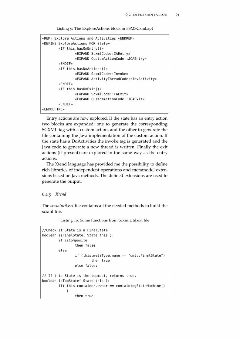
6.2 implementation 61
Listing 9: The ExploreActions block in FSMSCxml.xpt
«REM» Explore Actions and Activities «ENDREM»
«DEFINE ExploreActions FOR State»
«IF this.hasOnEntry()»
«EXPAND ScxmlCode::CAEntry»
«EXPAND CustomActionCode::JCAEntry»
«ENDIF»
«IF this.hasDoActions()»
«EXPAND ScxmlCode::Invoke»
«EXPAND ActivityThreadCode::InvActivity»
«ENDIF»
«IF this.hasOnExit()»
«EXPAND ScxmlCode::CAExit»
«EXPAND CustomActionCode::JCAExit»
«ENDIF»
«ENDDEFINE» �Entry actions are now explored. If the state has an entry action
two blocks are expanded: one to generate the correspondingSCXML tag with a custom action, and the other to generate thefile containing the Java implementation of the custom action. Ifthe state has a DoActivities the invoke tag is generated and theJava code to generate a new thread is written. Finally the exitactions (if present) are explored in the same way as the entryactions.
The Xtend language has provided me the possibility to definerich libraries of independent operations and metamodel exten-sions based on Java methods. The defined extensions are used togenerate the output.
6.2.5 Xtend
The scxmlutil.ext file contains all the needed methods to build thescxml file.
Listing 10: Some functions from ScxmlUtil.ext file
//Check if State is a FinalState
boolean isFinalState( State this ):
if isComposite
then false
else
if (this.metaType.name == "uml::FinalState")
then true
else false;
// If this State is the topmost, returns true.
boolean isTopState( State this ):
if( this.container.owner == containingStateMachine()
)
then true
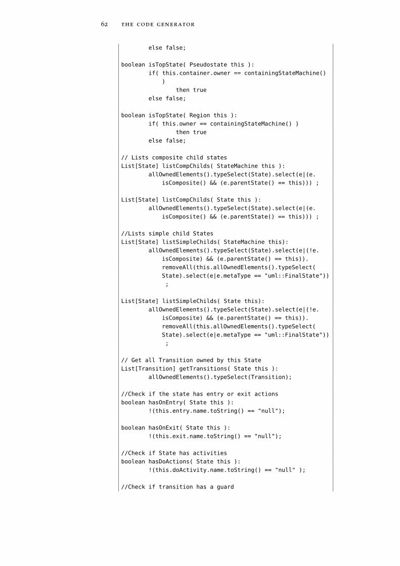
62 the code generator
else false;
boolean isTopState( Pseudostate this ):
if( this.container.owner == containingStateMachine()
)
then true
else false;
boolean isTopState( Region this ):
if( this.owner == containingStateMachine() )
then true
else false;
// Lists composite child states
List[State] listCompChilds( StateMachine this ):
allOwnedElements().typeSelect(State).select(e|(e.
isComposite() && (e.parentState() == this))) ;
List[State] listCompChilds( State this ):
allOwnedElements().typeSelect(State).select(e|(e.
isComposite() && (e.parentState() == this))) ;
//Lists simple child States
List[State] listSimpleChilds( StateMachine this):
allOwnedElements().typeSelect(State).select(e|(!e.
isComposite) && (e.parentState() == this)).
removeAll(this.allOwnedElements().typeSelect(
State).select(e|e.metaType == "uml::FinalState"))
;
List[State] listSimpleChilds( State this):
allOwnedElements().typeSelect(State).select(e|(!e.
isComposite) && (e.parentState() == this)).
removeAll(this.allOwnedElements().typeSelect(
State).select(e|e.metaType == "uml::FinalState"))
;
// Get all Transition owned by this State
List[Transition] getTransitions( State this ):
allOwnedElements().typeSelect(Transition);
//Check if the state has entry or exit actions
boolean hasOnEntry( State this ):
!(this.entry.name.toString() == "null");
boolean hasOnExit( State this ):
!(this.exit.name.toString() == "null");
//Check if State has activities
boolean hasDoActions( State this ):
!(this.doActivity.name.toString() == "null" );
//Check if transition has a guard
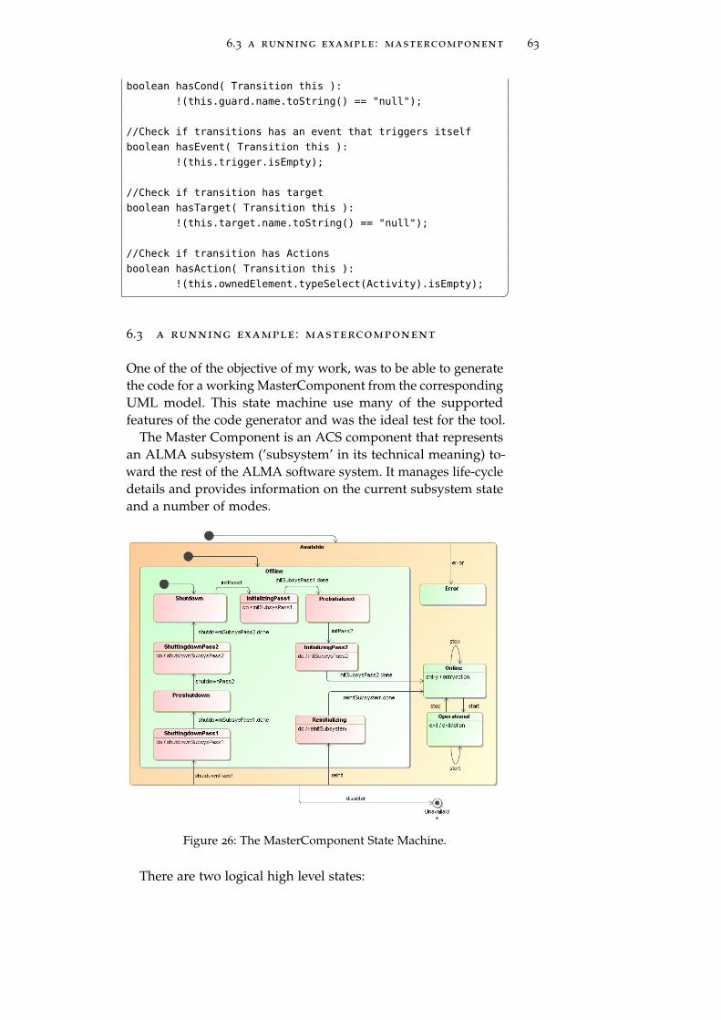
6.3 a running example : mastercomponent 63
boolean hasCond( Transition this ):
!(this.guard.name.toString() == "null");
//Check if transitions has an event that triggers itself
boolean hasEvent( Transition this ):
!(this.trigger.isEmpty);
//Check if transition has target
boolean hasTarget( Transition this ):
!(this.target.name.toString() == "null");
//Check if transition has Actions
boolean hasAction( Transition this ):
!(this.ownedElement.typeSelect(Activity).isEmpty); �6.3 a running example : mastercomponent
One of the of the objective of my work, was to be able to generatethe code for a working MasterComponent from the correspondingUML model. This state machine use many of the supportedfeatures of the code generator and was the ideal test for the tool.
The Master Component is an ACS component that representsan ALMA subsystem (’subsystem’ in its technical meaning) to-ward the rest of the ALMA software system. It manages life-cycledetails and provides information on the current subsystem stateand a number of modes.
Figure 26: The MasterComponent State Machine.
There are two logical high level states:
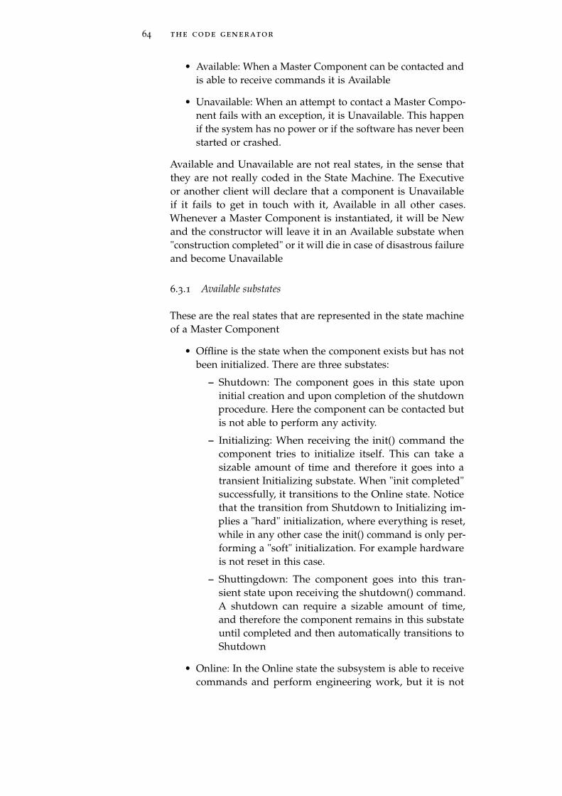
64 the code generator
• Available: When a Master Component can be contacted andis able to receive commands it is Available
• Unavailable: When an attempt to contact a Master Compo-nent fails with an exception, it is Unavailable. This happenif the system has no power or if the software has never beenstarted or crashed.
Available and Unavailable are not real states, in the sense thatthey are not really coded in the State Machine. The Executiveor another client will declare that a component is Unavailableif it fails to get in touch with it, Available in all other cases.Whenever a Master Component is instantiated, it will be Newand the constructor will leave it in an Available substate when"construction completed" or it will die in case of disastrous failureand become Unavailable
6.3.1 Available substates
These are the real states that are represented in the state machineof a Master Component
• Offline is the state when the component exists but has notbeen initialized. There are three substates:
– Shutdown: The component goes in this state uponinitial creation and upon completion of the shutdownprocedure. Here the component can be contacted butis not able to perform any activity.
– Initializing: When receiving the init() command thecomponent tries to initialize itself. This can take asizable amount of time and therefore it goes into atransient Initializing substate. When "init completed"successfully, it transitions to the Online state. Noticethat the transition from Shutdown to Initializing im-plies a "hard" initialization, where everything is reset,while in any other case the init() command is only per-forming a "soft" initialization. For example hardwareis not reset in this case.
– Shuttingdown: The component goes into this tran-sient state upon receiving the shutdown() command.A shutdown can require a sizable amount of time,and therefore the component remains in this substateuntil completed and then automatically transitions toShutdown
• Online: In the Online state the subsystem is able to receivecommands and perform engineering work, but it is not
6.3 a running example : mastercomponent 65
fully functional for science operation. The start() commandwould take it into the Operational state
• Operational: In the Operational state the subsystem is fullyfunctional and able to perform science. The stop() commandwould take it into the Online state.
• Error: When an error occurs that cannot be immediatelyautomatically recovered (but the component is not physi-cally destroyed and it is still possible to interact with it), theComponent goes into the Error state. A typical case is whenthere are hardware problems with devices in the subsystemor with resources like disk space. In such cases normallyan intervention from the operator is required. After theoperator has fixed the problem, he/she can issue an init()or shutdown() -> init() sequence to soft/hard initialize theMaster Component.
In principle a Master Component could automatically go fromOnline to Operational upon init (as requested by Pipeline) if thetwo states are effectively identical.
6.3.2 Substates of Online and Operational
Applications can define context specific substates for Online andOperational. Executive would not make general assumptions onsuch substates. They will be eventually used for context specificpurposes that require knowledge of the details of the state ma-chine of a specific subsystem. It would be in any case better to usecommon names for equivalent substates in different subsystems.Here are some examples:
• OK: everything is fine and alive
• IDLE / BUSY: as an alternative to OK for subsystems thatcan be just IDLE waiting for commands or are BUSY andtherefore cannot perform other actions in parallel. For "in-termediate" situation, the usage of OK is usually better.
• RECOVERING: when a subsystem is recovering from atemporary bad situation/error
6.3.3 A few modifications
Starting from the original concept of the MasterComponent asdeveloped in ESO, I made some changes to the model. First of allI added a default state to all the composite states, following theguidelines I have emphasized in the first part of my work. Theseinitial states are needed to identify the default starting substate
66 the code generator
in a composite state. Then I added events to the transitions.Among these, there are some special ones. These events are called".done events" and they are generated in the state machine whena DoActivity, started in the substates, has finished his job. This isdone every time an external service is called via the <invoke>tag, as stated in the SCXML standard. I also added some entryand exit actions for testing purposes.
6.3.4 The generated files
The generator will produce a Java application. The following filesOnce the files aregenerated developers
have only to writethe code for actions
and activities
are created starting from the model:
• StatemachineName.xml: the SCXML model
• Application.java: the main class containing informations anddata for the executor
• JavaInvoker.java: the class implementing Invoker. For eachactivity an instance of JavaInvoker is created. This willlaunch the corresponding thread with the implementationof the activity through the start() method.
• ActivityThread.java: a generic class for activity threads. Inthis class there is the implementation of the generic stop()method for the activity threads
• MyTreadActivityName.java: for each activity a specific classis generated. These classes extend ActivityThread.java andmust be filled with the correct implementation of the Ac-tivities. When the activity is finished a special event (*.in-voke.done) is sent to the parent state. This must be the lastgenerated event from the thread.
• StatemachineNameActionList.java: create the list of CustomActions used in <onentry> and <onexit> blocks
• CAActionName.java: a class for each custom action contain-ing the implementation of the custom action
• CustomActionListMap.txt and DoActivitiesMap.txt: two textfiles with the list of Activities and Actions and the namesof the respective Java classes. To be used in future for adifferent mapping (each action or activity could be mappedas a method of a class).
The generated files must be filled with the desired implemen-tation of actions and activities. Developpers have only to writethe desired implementations for actions and activities. Only thefiles MyTreadActivityName.java and CAActionName.java have to bemodified with hand-written code.

6.3 a running example : mastercomponent 67
To run the generated application Application.java must bestarted. The application will launch the SCXMLExecutor and onthe console window a very basic interface will log events, currentstates and transitions. Events can be fired from the console. Theapplication use the SCXML model to react to the events.
The application behave as expected: the SCXML model is cor-rectly interpreted. In addition DoActivities are implemented asthreads, to model the concurrency in the execution of the pro-cesses. If the state where the DoActivity is called is left the activitythread is stopped as as provided in the standards.

7C O N C L U S I O N S A N D F U T U R E W O R K
Contents7.1 Targets achieved 697.2 What to do next? 70
I developed this project working at the headquarters of the Eu-ropean Southern Observatory, located in Garching bei München,Germany. Here I worked for the Software Development Divisionin a team of 20 people.
In this work I addressed the following topics:
• A first part where I gave an introduction on the ModelDriven Development principles and on the statecharts for-malism, to give to the reader the basic knowledge neededto better understand my work.
• A description of the standards adopted to model state ma-chines in this project (UML and SCXML).
• A brief introduction on the available tools used to editand manage models and useful for the automatic codegeneration.
• The mapping proposal I developed and used to transform aUML model in the corresponding SCXML model. A formalmapping for this kind of transformation has never beenpresented in the literature.
• The design and the implementation of a code generatorcapable of producing code for an application. The logicof the application is based on the state machine describedusing an SCXML model.
7.1 targets achieved
With my work I achieved all the prefixed objectives. First of all,staring from a UML state machine model, the correspondingSCXML model is properly generated. All the features of themodel are translated with using the correct SCXML syntax.
The skeleton of the application is generated. The ApacheSCXML Engine is enclosed in the application and is used toparse the SCXML model. The model encloses the logic of the
69
70 conclusions and future work
application and is used by the SCXML engine to react to theexternal events.
Developers have to fill the generated skeletons with hand-written code. This code tie the application to the implementationdetails.
7.2 what to do next?
Once the design of the application is defined, is time to focus onthe refactoring of the code. The application should be modifiedto run as an ACS component. People at ESO are now working tointegrate my project in the ACS Code Generator, a tool capableof generate Java application for the ALMA platform.
Here follow possible developments of this work:
• For the moment the generated code is for a Java application.Next step may be to generate in a different language, likeC++, and for a different platform like the VLT softwareplatform.
• The automatic regression testing procedure of the codeshould be implemented to check that the application behaveproperly. A model for this purpose should be designed anda test script prepared.
• Another useful feature should be a simulation toolkit: avisual representation of the state machine with an high-lighting of the flow could help to monitor the applicationand to spot possible errors on the model.

Part III
A P P E N D I X

AC O D E L I S T I N G S
a.1 the code generator
The complete listings of the developed tool could be downloadedfrom the page of the project on Google Code. The home page ofthe project can be reached browsing following URL:
http://acsccg.googlecode.com
Everyone can download the code using a svn client. Use thiscommand to anonymously check out the latest project sourcecode:
# Non-members may check out a read-only
# working copy anonymously over HTTP.
svn checkout http://acsccg.googlecode.com/svn/trunk/
acsccg-read-only
The gsmecg folder contains the full Eclipse project, with theexamples used to define the mapping and the test models.
Here follows a description of the structure of the project.gsmecg is the main folder of my project.
• src: this folder contains all the source code. The file work-flow.mwe with the sequence of the operations to be executed,the file constraints.chk contains all the rules for the modelsas specified in the mapping phase.
– In the templates folder you can find all the templatefiles used to explore models. The file are written usingThe Xtend and Xpand languages.
• lib: in here are all the libraries needed to run the codegenerator and the generated application.
• src-gen: this folder is used to store the generated application.
• examples: here you can find all the examples used to developthe code generator. In every folder there is the MagicDrawfile (.mzip) and the exported model in XMI format.
73

B I B L I O G R A P H Y
[1] Model to text (m2t) eclipse project. URL http://www.
eclipse.org/modeling/m2t/.
[2] Qt labs website. URL http://developer.qt.nokia.com.
[3] Commons SCXML, July 2010. URL http://commons.apache.
org/scxml/.
[4] UML specification, May 2010. URL http://www.omg.org/
spec/UML/2.3/.
[5] State Chart XML (SCXML): State machine notation for con-trol abstraction, December 2010. URL http://www.w3.org/
TR/2010/WD-scxml-20101216/.
[6] Astronet website, 2011. URL http://www.astronet-eu.
org/.
[7] The atacama large millimeter/submillimeter array, March2011. URL http://www.eso.org/sci/facilities/alma/.
[8] The european extremely large telescope ("e-elt") project,March 2011. URL http://www.eso.org/sci/facilities/
eelt/.
[9] La silla paranal observatory, March 2011. URL http://www.
eso.org/sci/facilities/lpo/.
[10] Eso website, 2011. URL http://www.eso.org/.
[11] Eso - the very large telescope, 2011. URL http://www.eso.
org/paranal/.
[12] L. Andolfato and G.Chiozzi. Generic state machine enginesoftware requirement specification.
[13] Thomas J. Bergin and Richard G. Gibson. History of Program-ming Languages. Addison Wesley, 1996.
[14] Bruce Powel Douglass. Uml statecharts. Embedded SystemsProgramming, January:22–42, 1999.
[15] G. Filippi, P. Sivera, and F. Carbognani. Software engineeringpractices for the ESO VLT programme, 2001.
[16] David S. Frankel. Model Driven Architecture: Applying MDAto Enterprise Computing. Wiley, 2003.
75

76 bibliography
[17] Erich Gamma, Richard Helm, Ralph Johnson, and John M.Vlissides. Design Patterns: Elements of Reusable Object-Oriented Software. Addison-Wesley, 1995.
[18] G.Chiozzi, A.Caproni, R.Cirami, P.Di Marcantonio, D.Fugate,S.Harrington, B.Jeram, M.Plesko, M.Sekoranja, H.Sommer,and K.Zagar. The alma common software, acs status anddevelopments, 2005.
[19] Roberto Gilmozzi and Jason Spyromilio. The 42m euro-pean elt: status, 2008. URL http://www.vt-2004.org/sci/
libraries/SPIE2008/7012-19.pdf.
[20] David Harel. Statecharts: a visual formalism for complexsystems. Science of Computer Programming, 8:231–274, 1987.
[21] Object Management Group. MDA specifications, August2010. URL http://www.omg.org/mda/specs.htm.
[22] Object Management Group. UML Superstructure specifica-tion, May 2010. URL http://www.omg.org/spec/UML/2.3/
Superstructure/.
[23] Object Management Group. Object Management Groupwebsite, March 2011. URL http://www.omg.org/.
[24] Miro Samek. Practical UML Statecharts in C/C++, Sec-ond Edition: Event-Driven Programming for Embedded Systems.Newnes, 2008.
[25] Richard Soley. Model driven architecture, November 2000.URL http://www.omg.org/~soley/mda.html.
[26] Dave Steinberg, Frank Budinsky, Marcelo Paternostro, andEd Merks. Eclipse Modeling Framework. Addison Wesley,2008.
[27] Peter J. Young, Mario J. Kiekebusch, and Gianluca Chiozzi.Instrument control software requirement specification forextremely large telescopes.