model t data acquisition system - modeltecct · 1 crank tdas sensor wheel sensor throttle sensor...
TRANSCRIPT

1
TDAS CRANK
SENSOR
WHEEL
SENSOR
THROTTLE
SENSOR
Model T Data Acquisition System By Mike Kossor, WA2EBY
The big question on everyone’s mind following completion of engine enhancements,
adjustments or new accessory is; Does the car run any better than before? The question is
typically answered by a test drive. I’ve heard folks describe improved performance with
terms like: Runs stronger, pulls better, runs smoother, Revs higher, better top speed,
better acceleration and others but in the end, these are all just subjective conclusions
formed by someone who may have invested a lot of time, effort and money on those
repairs, adjustments or accessory. In my case, I am in the process of developing a new
method of coil point adjustment using a small hand held instrument called an Electrically
Cranked Coil Tester (ECCT) that permits each coil to be set for the same dwell time to
fire rather than the same coil current as it fires repeatedly similar to the stock ignition
system regulated by the timer.
The ECCT project is in the beta test phase where several volunteers adjust coils using the
new method and the ECCT then tested against coils adjusted using established tools like
the Hand Cranked Coil Tester (HCCT). A test plan was devised to yield quantitative
measurement between coils adjusted with the HCCT and the ECCT during road
performance testing. A ¼ mile course is selected with start and finish clearly marked.
The same car makes three timed runs from start to finish on the same course with the
same throttle and spark lever settings using stops on the quadrant. The times are
averaged to yield road performance test results for each set of coils; HCCT adjusted and
ECCT adjusted. Sounds good on paper but things are not exactly ideal in the field. The
differences in finishing times were very close but not always repeatable for the same set
of coils. The task of starting and stopping the stop watch is a major source of variation.
A better method was clearly needed. A chassis dynamometer would be great if one was
available locally but one isn’t and that really would not test actual road driving
performance. What was actually desired is a way to monitor engine RPM and vehicle
speed precisely timed starting from the moment the throttle is opened. A Model T Data
Acquisition System or TDAS was designed to do just that. A block diagram of the
TDAS system is illustrated in Figure 1.
Figure 1. TDAS Block Diagram
Lap Top
2
The throttle sensor signals the TDAS when the throttle opens indicating the beginning of
a road test. A sensor on the front crank pulley signals the TDAS each time the crank
shaft completes a revolution and another sensor mounted on a wheel signals the TDAS
each time the wheel competes a revolution. The TDAS starts an internal timer the
moment the throttle opens and reports the time a crank revolution and wheel revolution
occurs to a laptop computer. The laptop computer keeps track of all the events and
converts the data into engine RPM and vehicle speed when given the wheel diameter.
The TDAS provides a graphical display of the data on completion of the test signaled by
throttle closure and provides a data file that can be imported into Excel for further
analysis at a later time.
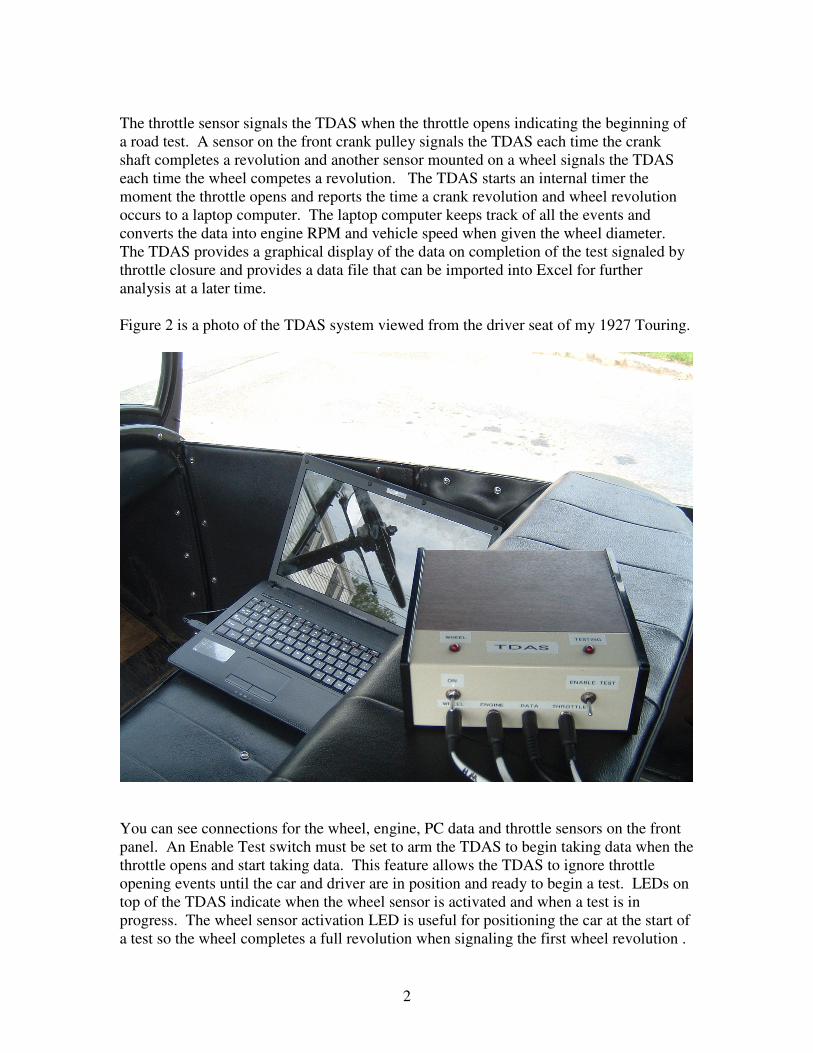
Figure 2 is a photo of the TDAS system viewed from the driver seat of my 1927 Touring.
You can see connections for the wheel, engine, PC data and throttle sensors on the front
panel. An Enable Test switch must be set to arm the TDAS to begin taking data when the
throttle opens and start taking data. This feature allows the TDAS to ignore throttle
opening events until the car and driver are in position and ready to begin a test. LEDs on
top of the TDAS indicate when the wheel sensor is activated and when a test is in
progress. The wheel sensor activation LED is useful for positioning the car at the start of
a test so the wheel completes a full revolution when signaling the first wheel revolution .
3
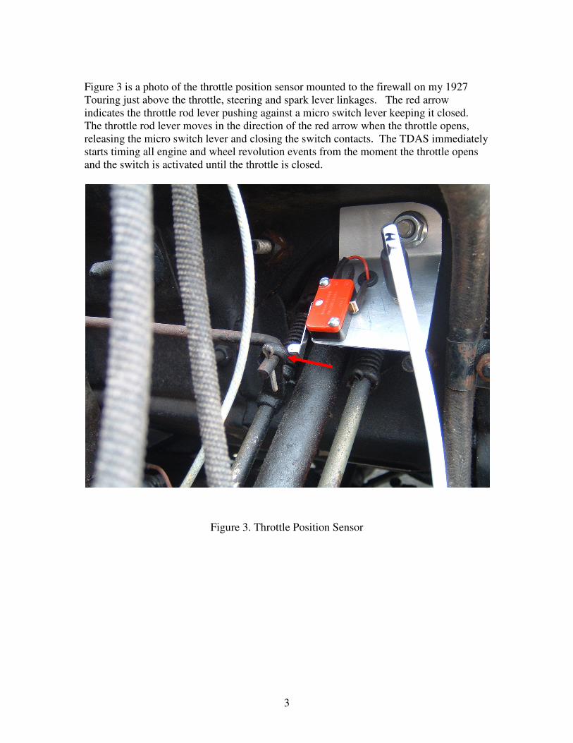
Figure 3 is a photo of the throttle position sensor mounted to the firewall on my 1927
Touring just above the throttle, steering and spark lever linkages. The red arrow
indicates the throttle rod lever pushing against a micro switch lever keeping it closed.
The throttle rod lever moves in the direction of the red arrow when the throttle opens,
releasing the micro switch lever and closing the switch contacts. The TDAS immediately
starts timing all engine and wheel revolution events from the moment the throttle opens
and the switch is activated until the throttle is closed.
Figure 3. Throttle Position Sensor

4
Figure 4 is a photo of the crank sensor used to monitor engine RPM. The camera was
positioned just to the right of the timer for a side view of the crank pulley. A thin blue
strip of aluminum is glued to the crank pulley and used to actuate an optical sensor
mounted to a circuit board that is clamped to the frame using C Clamps. Nothing is
permanently attached to the car and is easily removable when testing is completed.
Figure 4. Crank Shaft Sensor
Optical
Sensor
New
Day
Timer
5
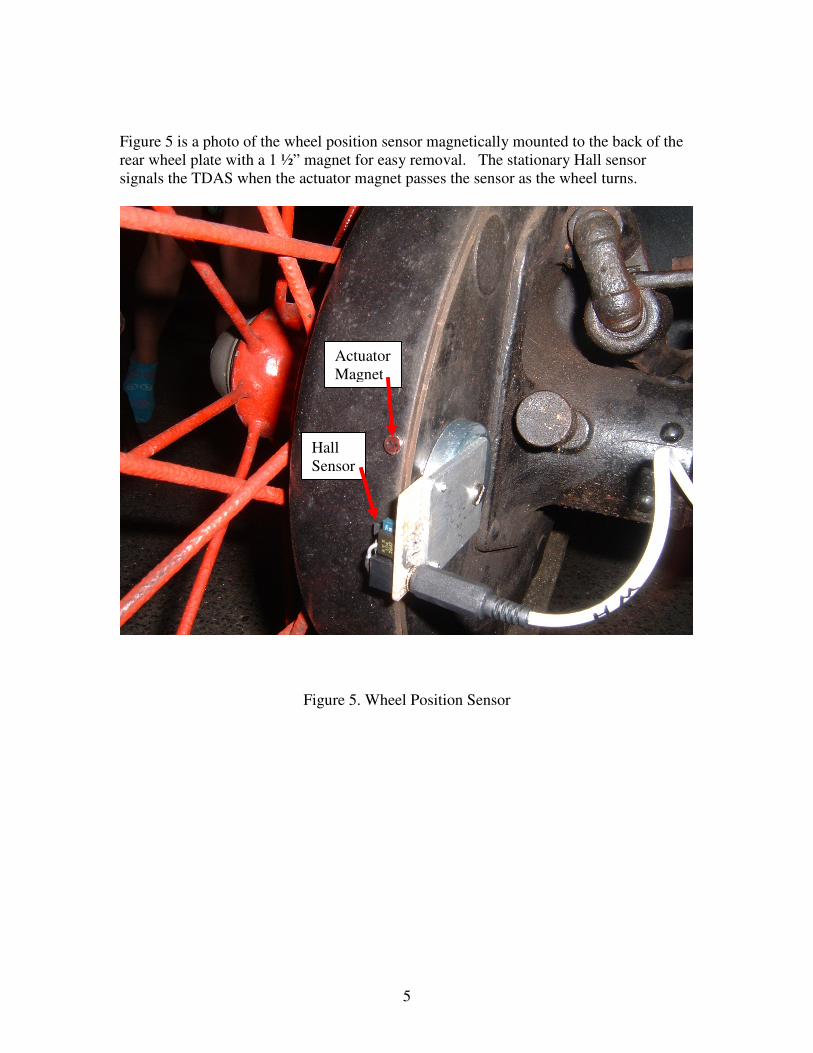
Figure 5 is a photo of the wheel position sensor magnetically mounted to the back of the
rear wheel plate with a 1 ½” magnet for easy removal. The stationary Hall sensor
signals the TDAS when the actuator magnet passes the sensor as the wheel turns.
Figure 5. Wheel Position Sensor
Actuator
Magnet
Hall
Sensor

6
Figure 6 is a photo of the test course used to run performance comparisons. This is an
industrial section of my town that is lightly traveled on weekends. The road has a slight
incline to add some challenge for the test vehicle. Look carefully and you can see my
1927 Touring nearing the end of a performance test run. The throttle is closed at this
point and the data is logged for further analysis later.
Figure 6. The 1927 Touring Completing a Test Run on the Test Course

7
An example of the TDAS Graphical User Interface (GUI) is illustrated in Figure 7. This
is the data taken on the test course using a set of coils operating on magneto. The red
trace is velocity in MPH and the green trace is engine RPM. Looking at the engine RPM,
you can see how the engine responds to the throttle opening and the clutch engaging from
the starting position. There is an initial transient in RPM then an exponential rise as
engine speed rises in low pedal. The transition is made from low pedal to high pedal at
approximately 7 seconds. The throttle remains wide open during this transition. Engine
speed slows linearly with time as the gear ratio changes until it resumes an exponential
increase in speed. Note that the rate of acceleration changes on the red velocity trace at
the transition from low pedal to high pedal.
Figure 7. TDAS Data Logged During a Test Run on the Course

8
Data captured during a longer test run is illustrated in Figure 8. The car accelerated from
0 to 44.25MPH in just over 60s with throttle and spark lever set to the last notch on their
respective quadrant. The throttle was closed slightly at 62 seconds to slow down for
traffic. Subsequent accelerations and decelerations are captured along with the
corresponding engine RPM responsible for vehicle travel.
Figure 8. TDAS Data Logged During Longer Test Run

9
An ignition performance comparison often discussed is operation on magneto versus 12V
battery versus 6V battery so I thought a TDAS data comparison would be of interest.
The test was done using a new day timer and a set of professionally adjusted set of coils.
The timer contacts were cleaned using fine steel wool just prior to the test. The spark rod
was set to the same position for each run at the last notch on the quadrant and not moved.
Each run stated at the same position on the road. The throttle was opened to the last
notch on the quadrant and not moved. Shifting from low to high pedal occurred at the
same point on the road when the front wheel reached a marked spot. Note the engine
speed read on the right y-axis barely gets above 2000 RPM on 6V battery while it just
passes 2300 RPM operating on magneto and 12V battery operation. There is little
difference in vehicle speed for the first 4.5 seconds then the lower engine RPM operating
on 6V becomes evident. 12V performance is essentially equal to magneto operation as
many have speculated or concluded. The jagged variations in the velocity and engine
speed are caused by bumps in the road.
0
200
400
600
800
1000
1200
1400
1600
1800
2000
2200
2400
2600
2800
3000
0
2.5
5
7.5
10
12.5
15
17.5
20
22.5
25
27.5
30
32.5
35
37.5
0 1 2 3 4 5 6 7 8 9 10 11 12 13 14 15 16 17 18 19 20 21 22 23 24 25 26 27 28 29 30E
ng
ine
Sp
ee
d (
RP
M)
Ve
locit
y (
MP
H)
Time (s)
TDAS Data: Professionally Adjusted Coil; Mag vs 6V vs 12V
ProMagV
Pro12VV
Pro6VV
ProMagR
Pro12VR
Pro6R
Figure 9. TDAS Data Comparison: Magneto vs 12V vs 6V Battery Operation
Finally, the TDAS was used to compare coils adjusted with the ECCT for equal and
consistent dwell time with professionally rebuilt and expertly adjusted coils using well
established methods and tools. The performance comparison test results are illustrated in
Figure 10. The small bumps in vehicle speed at 8.9, 13.5 and 20 MPH coincide with
patches in the road that cause bumps in the ride. It is easy to see from the chart the
vehicle rate of change of speed with respect to time (vehicle. acceleration) and engine
rate of speed with respect to time (engine acceleration) are nearly identical. The same
can be said for vehicle speed and engine speed. The same professionally adjusted coils
were used for this test comparison but performance is slightly better than recorded during
the previous magneto versus battery testing. A few variables that were different are the
outside temperature and gas. It was in the low 80s during the ECCT versus HCCT
testing but in the low 60s for the magneto versus battery testing. Gas was used from the
same station and same octane but from different days. Fuel shut off valve and fuel

10
mixture settings may have also had slightly different settings from day to day testing but
remain fixed during testing on a given day. Fuel mixture setting might make for
interesting road performance comparison testing using the TDAS in the future.
0
200
400
600
800
1000
1200
1400
1600
1800
2000
2200
2400
2600
2800
3000
0
2.5
5
7.5
10
12.5
15
17.5
20
22.5
25
27.5
30
32.5
35
37.5
0 1 2 3 4 5 6 7 8 9 10 11 12 13 14 15 16 17 18 19 20 21 22 23 24 25 26 27 28 29 30
En
gin
e S
pe
ed
(R
PM
)
Ve
hic
le S
pe
ed
(M
PH
)
Time (s)
ECCT Adjusted Coils Vs. HCCT Adjusted Coils
ECCTV
PROV
ECCTR
PROR
Figure 10. TDAS Data Comparison of ECCT vs HCCT Adjusted Coils
In summary, a quantitative method of assessing engine and vehicle performance was
presented that simultaneously monitors engine speed and vehicle speed. Data logging
synchronized with throttle opening facilitates A/B comparisons between engine or drive
train performance modifications. Ignition operation on 12V battery is essentially equal
to magneto operation in terms of engine and vehicle speed. Acceleration on 6V battery
notably lags performance on magneto or 12V battery due to lower top engine speed.
Coils adjusted using the ECCT based on equal and consistent dwell time perform
equivalent to HCCT adjusted coils. Folks interested in learning more about the
development of the ECCT are invited to visit the website at www.modeltecct.com
About the Author
Mike Kossor, WA2EBY holds a Master’s Degree in Electrical Engineering and has over
33 years of experience designing innovative solutions to complex electrical problems
ranging from highly linear microwave power amplifiers to the E-Timer electronic
ignition. Mike holds an Extra Class amateur radio license and drives a 1927 Touring. He
can be reached at: [email protected]