model submarines for dumb asses
DESCRIPTION
Instruction on building a model submarine and the parts and tools needed to build one. In depth guide by an expert in scratch building r/c subs.TRANSCRIPT

1
Acknowledgements 2
Building the Boat 60
Casting Resin Parts 57
Conclusion 79
Forward 3
Introduction 4
Making a Balsa Wood Master 31
Making Hull Molds 51
Making the Hull Masters 16
Making the Missile Deck 48
Making the Sail, Deck and Appendages 35
Materials 7
Props, Fittings, Mast and Scopes 59
Researching your Project 6
Running the Boat 76
Stern Plane Masters 44
The Basics of Vacuum Forming 78
Tools 9
Trimming The Boat 75
Watertight Cylinders 10

2
Acknowledgements It would be difficult if not impossible to mention everyone who has helped me over the years. In fact, it would take an entire book just to do that. I apologize in advance to anyone I’ve forgotten, but I’ve learned so much in so many different venues, my memory tends to fail. I do know though, that I must start at the top of the page by thanking the late, great John Chambers, who was a brilliant special effects make up artist (the original Planet Of The Apes). I was still wet behind the ears and “looking to get into the movie biz” when he first hired me in 1979-1980. He took me under his wing and taught me valuable lessons that have carried over into my model building some 30 years later. Rick Stratton. My good friend Rick and I worked on numerous monster and sci-fi film projects over the years. We’ve seen each other through thick and thin, but mostly thin. The Skotak Brothers. Bob and Denny are amazing visual effects artists, I worked with them on such films as The Terminator 1 & 2 and Batman Returns. They taught me many things, especially to be inventive. I learned how to utilize readily available materials, simple things like Popsicle sticks, which are just fine if they get the job done. They do, and I use them frequently. David Merriman. Founder of the Cabal Report, an up to the minute intelligent internet watch dog for modelers everywhere and a fabulous source of no b.s. information. There’s no two ways about it, he taught me how to build a submarine. And also: My mother and Father My wife Gilly and daughter Beth David Welch Brian Stark Tim Smalley Jeff LaRue Wayne Frey Gantu Hassan Lothar Mentz Darrin Hathaway J.C.M. (you know who you are) Chris Nutting John Anderson Olivier Brilliet The Sub Committee All my friends at Sub Pirates My dog Phooka, my late night building buddy

3
Forward
In a day where CNC machines, model kits, and pre-assembled and pre-painted models can be bought
and used by the so-called ‘hobbyist’, I find it most refreshing to encounter a guy who practices the
almost forgotten craft of scratch model building: the fabrication of a miniature representation of a
prototype, using basic hand and machine tools working basic materials. Steve Neill is such a Craftsman.
There are few of us left.
This guy possesses an extraordinary base of experience: A graduate of the Roger Corman School of
Filmmaking, a modern day sweat-shop (long hours in the New Worlds Pictures facility, for little money,
working to nearly impossible deadlines). There he worked as an effects artist designing, applying, and
maintaining make-up appliances as well as the building and rigging of effects miniatures. Today Steve
continues his motion picture and TV work designing and producing CGI effects for the industry.
Steve has also been influential in the r/c model aircraft industry; having designed and produced ducted
fan jet models and related products for that end of the r/c vehicle hobby. No armchair builder he, Steve
is also noted as a very hot model jet pilot.
Steve Neill’s methodical and careful approach to anything he builds is a study in how-things-should-be-
done. And that’s just what this book does: it will show you, employing no-nonsense jargon coupled with
carefully composed photos and graphics, how to scratch-build an r/c model submarine hull.
Additionally, Steve describes some of the approaches taken to propel and control the model submarine,
either on the surface or submerged.
David Douglass Merriman III

4
Introduction I was born in San Francisco in 1952 into a family of artists and musicians. My father, an artist and engineer worked designing submarines at Mare Island. Because of him I developed an early fascination for WW11 submarines, airplanes and all things military from that period. Unfortunately for me, he was killed when I was quite young and well before I enjoyed any success in my career.
In the early 70’s I moved from the bay area to Los Angeles in order to pursue my newly found passion for special effects make up. It was all about monsters, creatures and aliens for me. I worked hard, and made friends and contacts. I was also lucky enough to be in Hollywood at a time when this work was plentiful in America. I learned how to sculpt and make molds, mechanics, puppet and puppeteering, prosthetic make up and miniatures, whew!! Computers and computer graphics would come later.
Right around 1985 technology was such that the movement or action of creatures, puppets and monsters, were pretty much controlled by multitudes of cables and wires. Such was my world until I discovered remote controlled airplanes, when life as I knew it ceased to exist. My work and the discovery of remote control crossed over and fed off each other. The more I learned about one, the more I could adapt that knowledge and apply it to the other. One of the first times I used this adaptation was to make facial and mouth movements on the big singing moon man, “Mac To-Nite” for McDonalds. What a revelation, look Ma, no wires!! I became obsessed, and adept at flying most existing airplane models. Not content with that, I took to scratch building airplanes of my own design. I bragged that I could make anything fly, prompting my wife to challenge me to get a paper towel tube to fly…….. Of course by this time, (late 90’s) the internet had completely taken off and I had begun to use it to research various remote controlled models. In due course I came across the Sub-Committee and having just built my first submarine, the Dumas Akula (an excellent Christmas gift from my wife) I posted my work on their forum, E.Zone and ran smack into David Merriman, one of the best, if not the best model maker in the world. A truthful and amazingly fair human being, to say nothing of his talent, I am so pleased that he considers me a friend, and keeps me on the inside track of his modeling genius. He has guided me over the last 3 years whilst I produced 5 scratch built submarines and sold several kits. Clearly I could not have done it without his help. Another extremely talented gentleman is David Welch. He and I also met through Sub-Committee, which by the way is a really great venue for receiving and sharing information. I highly recommend it to anyone looking to join the brotherhood of the model-building submariners. It is my desire to prove that anyone serious about model making will be able to build the model they want without going into bankruptcy. In this book I will attempt to show how it is completely possible to

5
build your model entirely from scratch by using common household tools. Most materials can be found in your local hardware or hobby shop. Methods for building hull shapes and other parts without the use of a lathe, mill or CNC machine will be explained as well. Building water tight cylinders though, is best left to the experts, Mr. Merriman and Mr. Welch. I recommend purchasing one from either gentleman. The information on how to do that will be included later on. Enough talk, let’s start building.

6
Researching your Project When first starting to build any model, it’s always wise to research it. One of the best sources for information is the Internet. Google search the name of the boat you are interested in, and in return you will receive everything from pictures, to cross sections. There are also sites that offer complete plans for the boat you may be interested in.
There are many books available just for modelers. Some of the best of them come from Japan and Germany with great amounts of attention given to details. However there is no substitute for the human element, and to that end I mention my friend, Gantu Hassan. He is a veritable fountain of knowledge, and has been invaluable to me for connections
and resource material on the hobby Vom Original zum Modell are a series of German made books with extensive details on most of the German submarines from WW2. Personally it’s my favorite material on the subject. They are mostly printed in the German language but the pictures and plans speak very well for themselves. It is also possible to order plan sets directly from this same source rather than having to scan them from the book itself. Another source is from Japan and like their German counterpart these books cover a vast amount of detail and pictures of Japanese WW2 boats and more. Published by Gakken. The art work in these books is beautiful and you’ll want to put them on your wall. There are 100s of other sources but remember you can research your project on the web quite well and locate the whereabouts of these books on Amazon, EBay and other such sites. Once you get your reference material for your project. Absorb it well and get a feel for the boat. Study it until you know it by heart. Knowing your subject inside and out will be a great help with your build. A good tip is to try and find a movie that features the model you are interested in; it’s a great way to get detail right.

7
Materials In this section I will outline some the common materials and tools used to build a model from scratch. I use a wide variety of materials which can sometimes be found around the house. Others can be obtained from your local hobby store, hardware store or ordered online. I will be teaching you two methods of making a hull. One built with balsa construction. The other built from foam and a hot wire cutter construction. There are two methods for making hulls. Fiberglass lay up and vacuum forming. The materials and tools list will reflect both
1. Cardboard. Using the cardboard that comes on the inside of most boxes that house plastic model kits, is a great idea and also saves money. I use it to make templates from; these are made from scale plans, which I enlarge. I print out the cross sections, fit them to the cardboard and cut them to shape.
2. ABS plastic or styrene. This can be purchased at the local hobby shop or plastic supply store. It has a variety of uses from making scratch parts to templates, along with vacuum forming.
3. Balsa wood. Necessary if you plan to make a hull using the balsa formers and stringers method. 4. Blue foam. I prefer blue foam whenever I have to wire cut various sections. This can easily be
found at a builders supply stores like Home Depot or Lowes, look for it in the insulation aisle. 5. West Systems Epoxy. The top of the line product and also user friendly. The place to find it is
your local hobby store or boat store. As a thickening agent for the epoxy, always use Cabosil rather than micro balloons, it just works better.
6. RTV Silicone. I’ve found that GI 1000 RTV is one of the best silicone molding materials. It’s really easy to use and sets fast or slow depending on the catalyst used. It sticks to nothing but its self and regular household Vaseline makes a great release agent. It’s a very stable material and has little or no reaction to contaminates, unlike other RTVs. This material can be found at some hobby shops, or at most plastic supply stores. It can also be ordered on line from Burman Industries, a great make up supply store, they have been in business for as long as I can remember good people too. Here’s a direct link to them www.burmanindustries.com
7. Ultra Cal 30. If you plan to vacuum form a hull, you will need this product. It is a dry plaster made from gypsum, that when mixed with water, dries very hard. With this material you can make mother molds and pour positives from your RTV molds to make ‘bucks’ that can be used to vacuum form over.
8. Fiber Glass Cloth. There a quite a few sources for this, the most common being a plastic supply or boating store. I generally use 4 oz. and 8 oz. weight cloth. My local hobby store actually carries glass cloth, so I can pick it up along with my West System Systems epoxy.
9. Evercoat Metal Glaze. This is a two part polyester product, unlike Bondo, this material is smoother and sands in minutes. It is readily available at a local auto supply store, such as Pep Boys, or Auto Zone.
10. Silicone mold release. PVA and Partall wax can be found at a good plastics supply store. 11. 3M 77 Spray Adhesive. Easily found at most art supply stores. You will use this product all
through the build, especially when gluing the foam hull sections together and assembling the templates.
12. Additional adhesives. It’s good to keep a few different kinds of adhesives on hand as you will use them frequently. Five minute epoxy and CA (super glue).
13. Sand paper. Both wet and dry are needed. 14. Sanding sponges.

8
15. Sanding bar. 16. Primer. There are lots of good primers out there; I think the best brand is DuPont (131 Gray) it
dries fast and is ready to go. However you do need to have an air brush and compressor set up. A good alternative is Krylon spray, white and ruddy red colors work, and any hardware store carries it this brand.
17. Modeling paints and brushes.

9
Tools
1. A Dremel tool. All hobby stores carry these. 2. A drill press is a good thing to have but if you don’t happen to own one, a standard drill will do
fine, along with a new set of drill bits. 3. A scroll saw can be a great aid in cutting parts. A hobby store will usually carry these but of
course if you have to, you can cut by hand, and sand to shape. 4. An airbrush is not costly and is a must for the serious model maker. Although spray cans and
hand brushing can be used, the airbrush will allow you greater control and choices. 5. A compressor. You can use anything from a small artist airbrush compressor to a larger shop
compressor. I find the shop compressor you can purchase from a hardware store works well and in most cases, costs about the same as an art compressor. This will come in handy for so many things, I highly recommend owning one.
6. Small file set. This will be helpful when it comes to evening out the drains and limber holes. 7. A good selection of small tools should include: screw drivers, Allen wrenches, tweezers, micro
drill bits, and needle nose pliers. Most of these are standard to anyone who has built models.. 8. Drafting tools and levels are a great help too. Triangles, squares and drafting templates can all be
had at the local art supply store. The templates are really handy for making scribed shapes on your models.
9. A set of calipers. 10. A surface tool is very useful for achieving exact demarcation lines. I use this tool for scribing
exact halves of my hull masters before molding. Then I use it to mark the water line. Just about any demarcation line can be made accurate in this way.
11. A perfectly level building board is a must. To insure that I have a level board no matter what surface I’m working on, I use a balsa building board. They are great for pinning things down.
12. If you plan to make a vacuum formed hull you will need a large vacuum form machine. If you can afford one, check out www.customformers.com . They can custom build you one to your specs. Of course, you can build your own. There are plans and books on the net that show you “how to” with simple building materials
purchased from any hardware store. You will also need a large shop vacuum. Many of the items listed above are already owned by the seasoned model maker.

10
Watertight Cylinders I will not demonstrate how to build watertight cylinders (WTC) in this book. I’d rather refer you to the vendors that have them already made and for sale. There are also do it yourself kits available from these same vendors. These cylinders are the heart of the boat. They keep out the water and the electronics dry. Using polycarbonate tubing in varying diameters as the compartment itself and Alumilite cast end caps with o-ring seals this cylinder can be opened and closed easily. The end caps are drilled and seal housings with silicone seals allow the prop shaft and push rods to move without leaking water.
Shown here is the D&E Subdriver created by David Merriman and marketed through www.caswellplating.com These are pre-built and already have the ballast system and the seals built in. All you have to do is mount your servos, RX, ESC along with the battery and you are ready to go. For improved safety and performance a Caswell “Angle-Driver” is a must.
This automatic pitch control will allow you drive the boat with better authority, maintaining pitch level at periscope depth. Should you ever lose radio signal in the deep, the fail safe will blow the ballast returning your investment to the surface. The D&E Sub-driver (WTC) uses a compressed gas system for ballast control. The copper cylinder seen in the diagram below photo stores the compressed gas by using propellant for airbrushing, which is injected into the copper cylinder through a Schrader valve.

11
A servo in the Sub-driver releases the gas into the ballast tank section, pushing the water out and back to sea (into existing surrounding water) though open holes on the bottom.
The boat surfaces.
To let the water back into the ballast tank, the servo is moved in the opposite direction, which in turn opens a valve on top of the cylinder allowing the section to flood.
The boat submerges Simple yet effective.
12
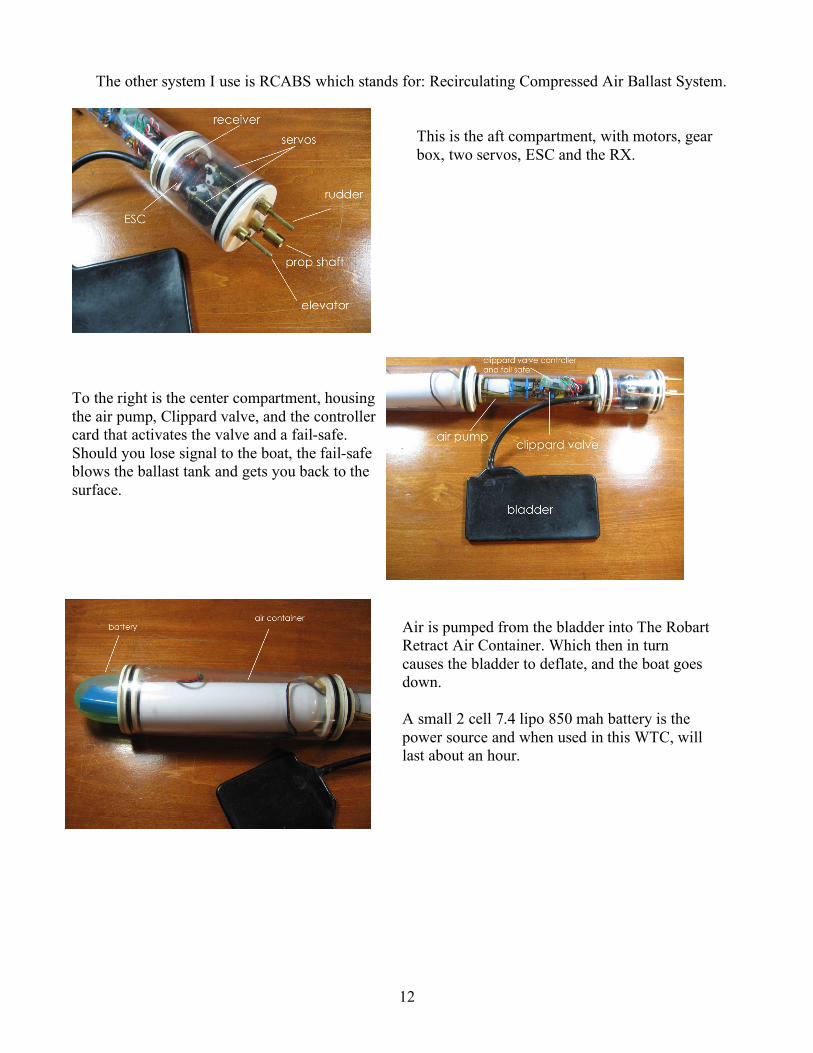
The other system I use is RCABS which stands for: Recirculating Compressed Air Ballast System.
This is the aft compartment, with motors, gear box, two servos, ESC and the RX.
To the right is the center compartment, housing the air pump, Clippard valve, and the controller card that activates the valve and a fail-safe. Should you lose signal to the boat, the fail-safe blows the ballast tank and gets you back to the surface.
Air is pumped from the bladder into The Robart Retract Air Container. Which then in turn causes the bladder to deflate, and the boat goes down.
A small 2 cell 7.4 lipo 850 mah battery is the power source and when used in this WTC, will last about an hour.

13
RCABS works by using an electric air pump inside the closed WTC. It draws air from the inside when you move the valve servo and the arm comes in contact with a micro switch that activates the pump. It also draws air from the WTC and moves it into a vinyl air bladder, as the air bladder fills, the boat goes up. This now creates a vacuum inside the cylinder so all you have to do is move the opposite servo again and it comes back in contact with the Schrader valve. This releases the air from the bladder and it is sucked back into the WTC deflating the bladder and, the boat submerges. The business end.
Both WTC systems use seals for the prop and control arm shafts. David Merriman (D&E Miniatures) makes a seal out of resin with an embedded o-ring inside. The control shaft passes from inside the dry chamber to the outside in the wet. It is this little 1/8” (or 1/16”) ID plumbing silicone o-ring alone, that keeps the water out of the dry chamber. If you always wanted to know how the water was kept out, now you know.
A view showing the inner workings of basic seal concept.
The seal is molded onto a shaft,
The finished product, ready to install in the cylinder end-cap.

14
Push-Rod Seals David Merriman sent me these pictures to illustrate the actual seals he makes.
The upper brass seal is the old style; the lower one is David’s new design.
Prop shaft seals and the Oilite bearing on the right.
In addition there are stuffing boxes and similar seals with brass casings that can be acquired and used. David Welch sells water type cylinder kits which consist of the tubing, pumps, bladders, end caps with o-rings and detailed instructions. He also includes a bill of materials and where to get them. . http://www.frontiernet.net/~bwelch/ You must however, have the skill and tools to finish the cylinder. You must be able to drill, tap and fabricate parts
BigDave’s WTC RCABS-2 as it arrived in the mail.
BigDave custom built this WTC for my Washington class sub.

15
The Angle Pitch Controller, depth control, fail safe, seals and other components can be purchased from www.caswellplating.com/models Scale props can be located from several sources, are such as Dumas, Engle, Raboesch and others. This is the basic information on WTCs. There are many ways to build one and many systems that have been built over the years and you can research this information on the net. Two of the best sources are www.subpirates.com
and the Sub Committee at www.subcommitte.com. The Sub Committee is the first model submarine organization. Along with many others, I started in this hobby with them.
16
Making the Hull Masters
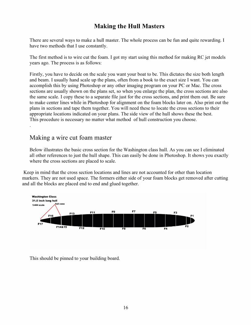
There are several ways to make a hull master. The whole process can be fun and quite rewarding. I have two methods that I use constantly. The first method is to wire cut the foam. I got my start using this method for making RC jet models years ago. The process is as follows: Firstly, you have to decide on the scale you want your boat to be. This dictates the size both length and beam. I usually hand scale up the plans, often from a book to the exact size I want. You can accomplish this by using Photoshop or any other imaging program on your PC or Mac. The cross sections are usually shown on the plans set, so when you enlarge the plan, the cross sections are also the same scale. I copy these to a separate file just for the cross sections, and print them out. Be sure to make center lines while in Photoshop for alignment on the foam blocks later on. Also print out the plans in sections and tape them together. You will need these to locate the cross sections to their appropriate locations indicated on your plans. The side view of the hull shows these the best. This procedure is necessary no matter what method of hull construction you choose. .
Making a wire cut foam master Below illustrates the basic cross section for the Washington class hull. As you can see I eliminated all other references to just the hull shape. This can easily be done in Photoshop. It shows you exactly where the cross sections are placed to scale.
Keep in mind that the cross section locations and lines are not accounted for other than location markers. They are not used space. The formers either side of your foam blocks get removed after cutting and all the blocks are placed end to end and glued together.
This should be pinned to your building board.

17
Take the printed-out cross sections, and cut them out with scissors gluing them to scrap model box cardboard with the 3M 77 adhesive.
Using the scroll saw or scissors, cut them precisely just to the outside of the line. Then using 120 grit sandpaper sand the edges until they are smooth and contoured.
You need to harden the edges of the cardboard and the best way I have found to do this, is use thin CA. Coat it lightly on the edges and once dry, sand again until it’s smooth. This way when you wire cut foam, the wire won’t drag or hang up on the edges.
18
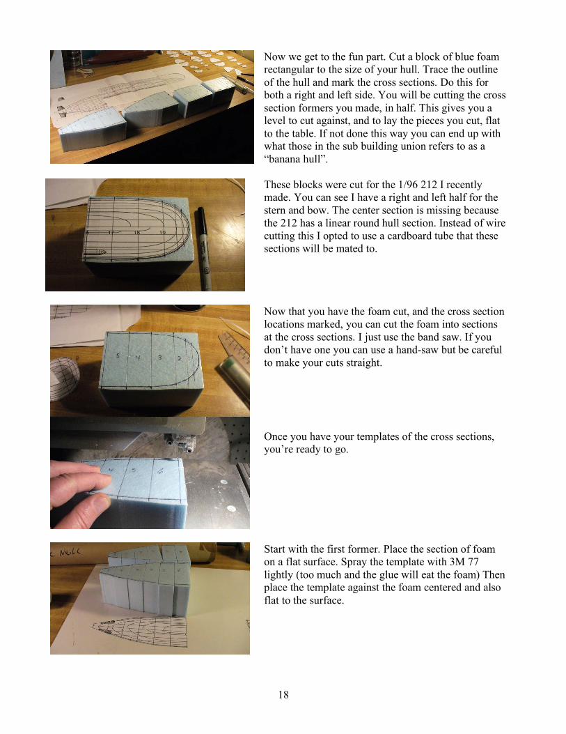
Now we get to the fun part. Cut a block of blue foam rectangular to the size of your hull. Trace the outline of the hull and mark the cross sections. Do this for both a right and left side. You will be cutting the cross section formers you made, in half. This gives you a level to cut against, and to lay the pieces you cut, flat to the table. If not done this way you can end up with what those in the sub building union refers to as a “banana hull”.
These blocks were cut for the 1/96 212 I recently made. You can see I have a right and left half for the stern and bow. The center section is missing because the 212 has a linear round hull section. Instead of wire cutting this I opted to use a cardboard tube that these sections will be mated to.
Now that you have the foam cut, and the cross section locations marked, you can cut the foam into sections at the cross sections. I just use the band saw. If you don’t have one you can use a hand-saw but be careful to make your cuts straight.
Once you have your templates of the cross sections, you’re ready to go.
Start with the first former. Place the section of foam on a flat surface. Spray the template with 3M 77 lightly (too much and the glue will eat the foam) Then place the template against the foam centered and also flat to the surface.

19
In the case of the 212 I started at the bow at station 6. (shown above) Number 5 template goes on the opposite side; make sure both are aligned well. This can be done with a straight edge. As you can see I marked center lines on the templates. As long as both templates are flat to the table and aligned to the center line you are good to go.
It is possible to construct your own wire cutter. Use a piece of nichrome wire hooked to a power supply with a rheostat. The nichrome wire is stretched between two pieces of 3/16th or larger piano wire, mounted into a larger wooden dowel. Piano wire is easily found at most hobby shops. The alligator clips are attached from the power supply. It doesn’t matter which side either plus or minus connect to. Once this is turned on, you can adjust the temperature so as you drag the wire through the foam and it cutting nice and slowly. Too much temperature will cause burning and erratic cutting. Use a 12-6 volt car battery charger as a source of voltage. Some friends I know use a train transformer.
Pictured left; my home made bow for larger work (to the right) and the commercial cutter available at most hobby shops, which runs on two D batteries and is very inexpensive.
Here you can see how I notched the piano wire to lock in the wire. Before you do any real cutting with any sections or templates, do some tests on some scrap foam. Get comfortable with the cutter first. Once you are comfortable, start cutting your first section. Make a couple of trial runs until you get it right.

20
Holding the bow and the section of foam sandwiched between the two templates in your hands slowly drag the wire through the foam along the two templates. If the wire cuts through too fast, the temperature is too high, just drag it through slowly, after a few times you will get the feel for it. Not to worry, you can fill any little mistake with Balsa fill and then sand to shape, you can still save that piece, don’t expect it to be perfect. Some times the wire will lift away which will cause a ridge, no problem. With the two templates still in place, use a sand bar and flat sand the templates and foam.
In this picture you can see the extensions added to the formers. This is sometimes done to get a better entry with the wire. If there’s a little error it’s usually a ridge and can be sanded away, but if you’re not hitting the mark these add-ons will really help you.
Begin the cut, as you drag the wire through; keep it even on both formers. Make sure you enter and exit at the same time.
Keep slowly dragging the wire through keeping even pressure against the former.
The cut foam before the formers are removed. The 3M holds them temporarily, so they can be removed later.

21
And here’s the final product. If only the real thing came out as well as my 3D renderings!
Here’s what the real thing looks like. Remember you can flat sand the hills or ridges with a sanding bar before you remove the formers.
You should now have something that looks like the above photo. Now all you do is remove the two templates and move on to the next section
From this point on to finish, repeat these simple steps for all sections both right and left, or top and bottom. Using a flat surface you can put these sections end to end and glue them together with 3M 77. By now, you should have something that looks like this.
You can make any shape you want this way. For the 212, I used a cardboard tube (shown in the background) that had contained some great sub plans. I cut it to the correct length then glued it to the bow and stern using 5 minute epoxy.

22
The blue painter’s tape holds the bow and stern sections in position. To make the deck: The template or former at the end of each section facing the cardboard tube was used to do this. I only used the top portion of the template for the deck and using a compass accommodated the curve that fits the deck. I placed the templates between a long section of foam, cut it to fit & wire cut it. I ran out of blue foam on this occasion and used white foam instead. I don’t normally recommend it.
As you can see in the picture I was using a Revell plastic model for further reference, but beware, some plastic models may look authentic but in most cases are grossly out of scale. In this rare case the Revell model is spot on according to the great German modeler Lothar Mentz.
The deck is moved into position and glued to the tube with 5 minute epoxy. If you are concerned about it setting up too fast before you have a true alignment, use 30 minute epoxy.
Remove the bow and stern sections. Shape them up a bit more before you mate them to the tube and deck. It’s very important that you are sure they are level and straight to a flat surface. An easy way to do this is with a laser level and by continually checking, until you are sure they are true

23
Check your tube to make sure both ends are parallel and true. Once you have done this you should have something that looks like this.
I have shaped and filled the foam sections using white Balsa fill purchased at any hobby store. This material is used all the time in model balsa aircraft construction. It sands very similar to balsa and was formulated just for this application. It also sands at nearly the same rate as the blue foam. This means fewer problems with hills and valleys. Sanding sponges work best for the smoothing and filling, they bend easy around the shape and are less likely to scuff or scratch the foam, which can cause more filling work.
It’s hard to get perfect, so just get it as smooth as you can. Just watch out for those “mountains”; valleys can be filled. Remember, later on when these shapes are glassed, there’s no going back! Glue the sections together permanently with epoxy. I used more Balsa fill and grafted everything together to make it all as smooth as possible. I also carved up the sail blank out of blue foam to see how it would all look. More about the sail later. First, the hull master gets finished. .
After a bit more shaping I made a straight line where the deck meets the hull. I used a straight edge and an Exacto knife. Make sure when you do this, that it matches the indentations in the hull. A bit of Balsa fill used when you sand, will serve to stiffen up the white foam, as it can be fragile. Once you are satisfied with the overall shape and fit, it is time to glass the hull.
To glass the hull I used 8 oz. cloth initially proceeded by two layers of 2 oz. and finally,1 oz. To make this an easier task, use 3M 77 sprayed on the master to lightly adhere the cloth, smoothing out the creases. Fiberglass cloth has a weave to it. Laid on the surface in the correct direction, you should use larger sections of glass cloth that can be stretched around corners, rather than cutting darts in the cloth, or using many sections. Always experiment with scraps so you get and feel for your cloth and technique.

24
On this particular master I decided to try laying the other layers of cloth over the first using a light coat of 3M 77, it worked well. Now all I had to do was soak this stuff with West Systems Epoxy. Before doing this, you should become familiar with the product, read the fact sheet. The ratio is 20 grams of catalyst to 100 grams of base. You can use fast or slow catalyst, depending on the room temperature.
For this hull I used only 50 grams of mixed epoxy. A little goes a long way. Using those disposable brushes you get from the hardware store, spread the epoxy on the glass, and allow it to soak in. If you have over laps of glass cloth showing don’t worry, you can sand it down. Don’t expect it to be perfect. Make sure you have no drips or puddles. Soak up excess with paper towel by dabbing the surface. This should have a dry look. Let it set up over night.
The next day take some 80 grit sand paper and sand it down as smooth as you can without sanding through the cloth. Mix up another 50 gram batch and glaze coat the entire surface. This fills in the weave the cloth has and makes a smooth surface. Wait 24 hours and sand it again. This makes the surface smooth ready for shaping, filling and sanding.
One of the greatest little tricks I have ever learned from the great master David Merriman III …Evercoat! Evercoat is two part filler that mixes like Bondo but sands the same as epoxy. It sets in minutes and is ready to sand. It sands easier than Bondo and matches the surface perfectly. In effect you can fix and make perfect anything with Evercoat. Really! Thanks David!!!!
I started by cleaning up the deck line where it meets the hull. To do this I first used the surface tool to scribe a straight and level line to follow. Set the hull master up so it can sit level to the table on all vectors. That’s X, Y and Z kids. Lock it down so it can’t move. The blue painters tape was used first to establish the line that I would follow with the surface tool.

25
Once the line was scribed and I was happy with it, I moved on to using a small amount of Evercoat to accent the edge.
When the Evercoat sets, you can flat sand removing any overflow. This makes the surface clean, and even with the deck. Now you can remove the tape, and you should have a strong demarcation line between the deck and hull.
I ended up doing this a few times while working on the hull. Sometimes it’s necessary, especially after you start spraying on primer, it shows every flaw, but you can always go back over it, improving each time. Next I filled and fixed all the valleys with Evercoat

26
For the sail deck fairing I used another template made from the plan’s top view. I was able to place this directly on the deck and tacked it down with a bit of thick CA. The template was made from model plywood.
Studying the plans, I drew in pencil, an approximate line, as to where the fairing blends to the deck. Then, using blue painter’s tape I masked the area to be filled. Keep it level. These little levels really help, they are small for model work. I got this one from an old tripod. You must make sure that the hull master is level too.
Next fill the gap with Evercoat, it will probably take took two layers. Then let that set up for about 15 minutes and sand it to shape. It will naturally contour to the template and the deck.
Once the tape is removed it should look like this.

27
In this photo you can just see a scribe line the rounds longitudinally along the mid section of the master. This was done with the surface tool to mark the left and right halves of the mold that will be done later. It also helps from this point on to make it easier to level the master as you now have a reference point.
You will now need to attach the stern plane roots. These will be used as a location to attach the fins, during the actual model assembly. To do this, I referred to the plans. Then I made 4 identical roots, using ABS plastic. Using the scribed center-line allowed me to accurately mark the geometry for their locations.
Using a pencil and making measurements I marked the hull as seen here. Always check against the plans as you go.
I glued the roots onto the hull using 5 minute epoxy. Filled the gaps with Evercoat and sanded.
The keel was made from hard balsa, based from the plans and attached to the bottom. I then filled and sanded it to contour and fit, with Evercoat. The red putty is Bondo spot filler; it comes in handy for those slight adjustments. It responds well to a light touch and fills scratches quite well.
28
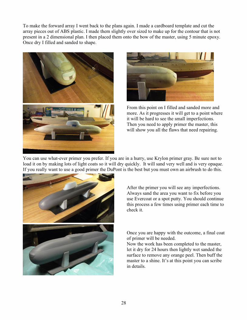
To make the forward array I went back to the plans again. I made a cardboard template and cut the array pieces out of ABS plastic. I made them slightly over sized to make up for the contour that is not present in a 2 dimensional plan. I then placed them onto the bow of the master, using 5 minute epoxy. Once dry I filled and sanded to shape.
From this point on I filled and sanded more and more. As it progresses it will get to a point where it will be hard to see the small imperfections. Then you need to apply primer the master, this will show you all the flaws that need repairing.
You can use what-ever primer you prefer. If you are in a hurry, use Krylon primer gray. Be sure not to load it on by making lots of light coats so it will dry quickly. It will sand very well and is very opaque. If you really want to use a good primer the DuPont is the best but you must own an airbrush to do this.
After the primer you will see any imperfections. Always sand the area you want to fix before you use Evercoat or a spot putty. You should continue this process a few times using primer each time to check it.
Once you are happy with the outcome, a final coat of primer will be needed. Now the work has been completed to the master, let it dry for 24 hours then lightly wet sanded the surface to remove any orange peel. Then buff the master to a shine. It’s at this point you can scribe in details.

29
I didn’t scribe or detail this master as it was slated to be vacuum formed. The vacuum forming would not show these scribed details so it was left out. As it turned out later this shape didn’t vacuum form well and so they were made with epoxy.
To scribe details use a small sharp rat-tail file and templates. You can purchase them at art or drafting supply stores. Some hobby stores carry stainless steel templates that are used for tank modeling and are excellent for this work. You can also make you own. Be creative!
This picture shows some tests I did on a similar surface.
Here are some of the templates and tools I use in the scribing process. The stainless templates are particularly useful.
You can also do this job using Chart tape. It comes in all kinds of sizes, right down to 1/64. It is great to simulate weld and panel lines. With weld lines you leave the tape on and primer over it. For making panel lines, lay on the tape and use primer over it. You should use about 4-5 thick coats over the tape and let it dry. Once it is dry remove the tape and lightly sand the ridges down, then you will have a clean panel line.

30
Here is the nearly complete 212 sail. This is an example for using the tape method. For this model I removed the tape. The real submarine has panel lines, not weld lines.
Here you can see the tape before primer. Also visible are vinyl tape templates for the doors and other details. The section has been sprayed many times with primer.
The end result is quite pleasing. Always experiment first when trying out these new tricks. Use scrap and try different shapes. Once comfortable you can try it out on your masters.

31
Making a Balsa Wood Master
Building a hull master out of balsa will appeal to the seasoned model airplane builder. I got started that way and thought for this particular hull of the Washington class submarine, I’d give it a try. Some of the methods are the same as those used for the foam master. So those steps will not be repeated. The cross sections are made the same way, but using balsa instead.
I used the above plan to glue to sheets of balsa for the top and bottom halves of this hull. Hee, two sheets of 3/32 balsa lightly tacked glued together.
Using the scroll saw I cut and sanded the balsa to shape. I marked the cross former locations and removed the print offs. I cut the cross sections out of balsa and sanded to shape.

32
Once I had all the cross sections cut, I glued them in the proper locations.
You can just see the cap strip balsa to the right. This will be used to plank strip the hull shape.
The planking is starting to take shape.
The planks are glued on with CA. I usually do a top strip and two side strips to lock the formers in position. Then proceed from there.
One of the advantages to using this method is the way the balsa strips planks continue the natural curve of the hull when bent over the cross sections.
33
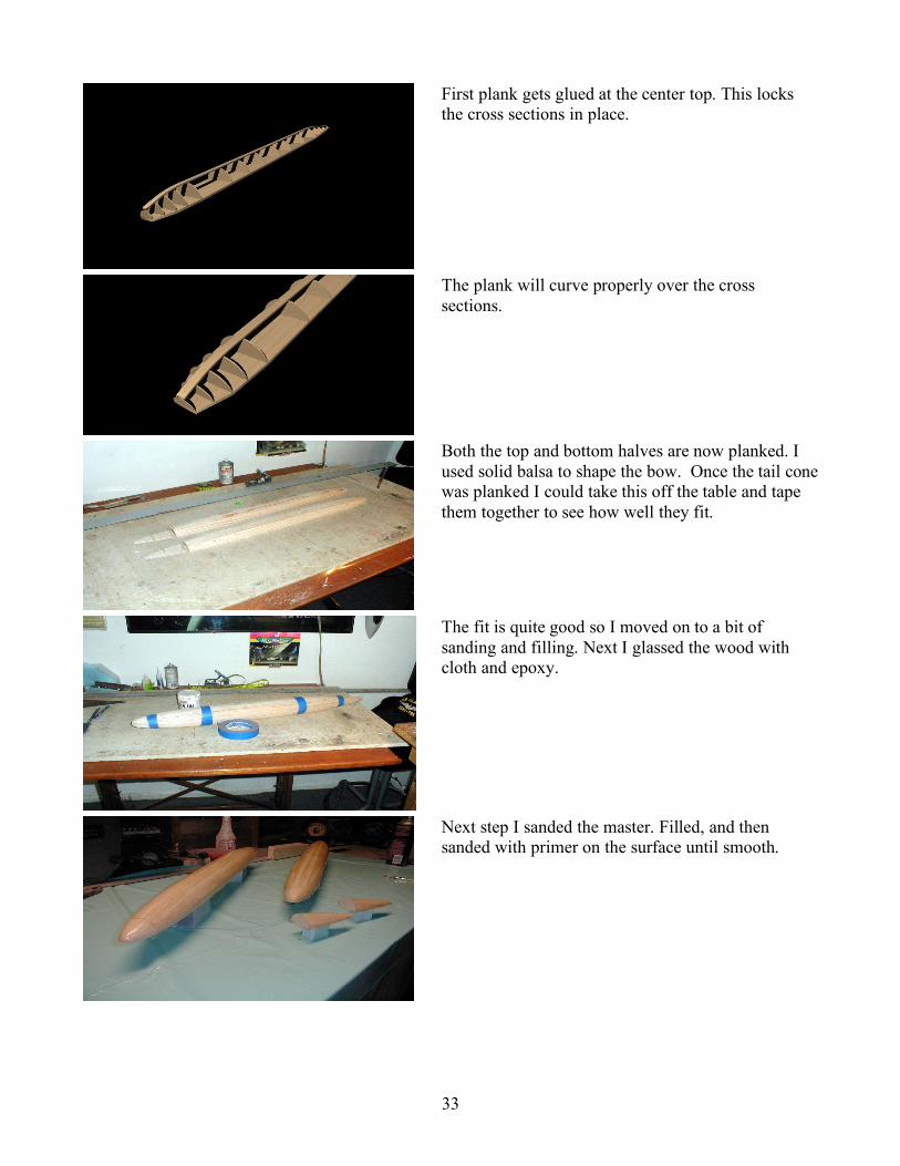
First plank gets glued at the center top. This locks the cross sections in place.
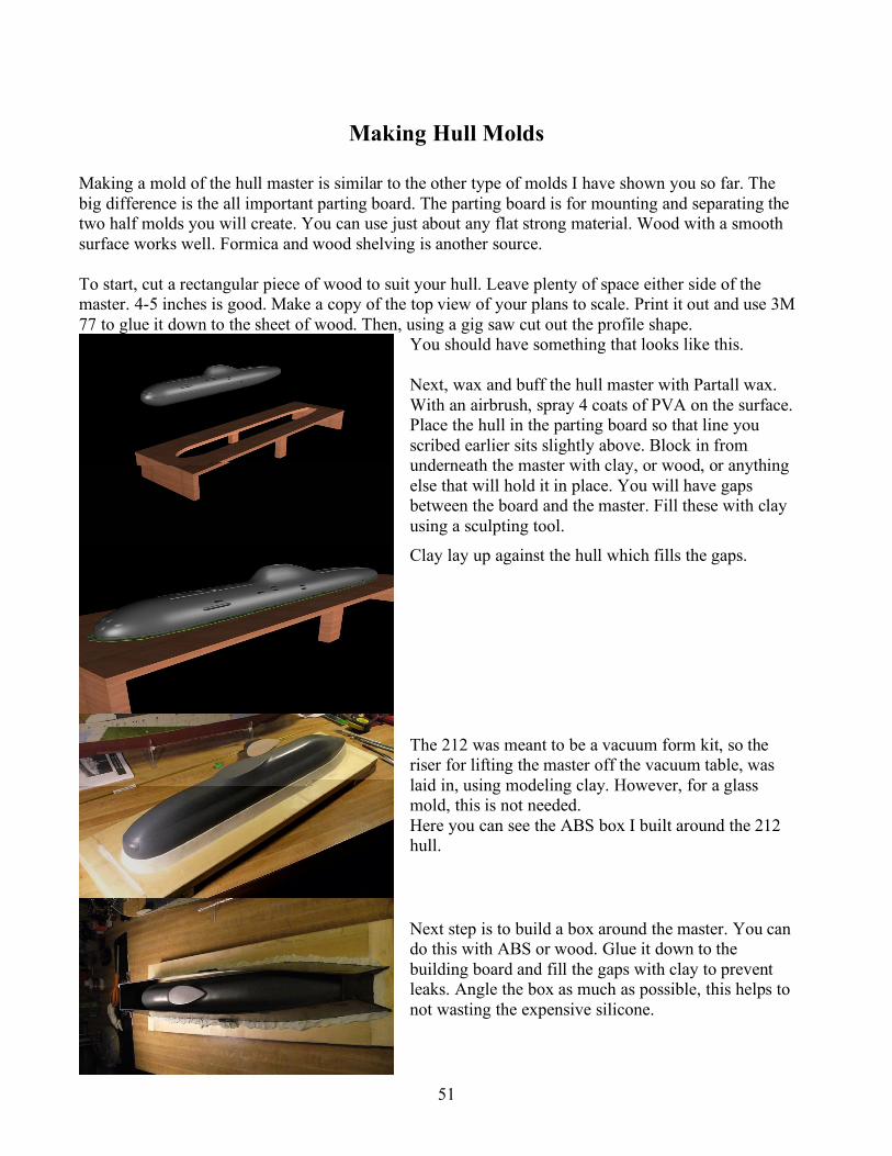
The plank will curve properly over the cross sections.
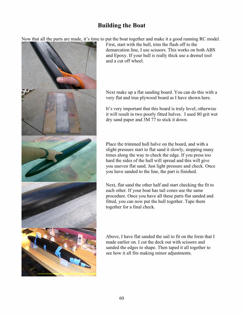
Both the top and bottom halves are now planked. I used solid balsa to shape the bow. Once the tail cone was planked I could take this off the table and tape them together to see how well they fit.
The fit is quite good so I moved on to a bit of sanding and filling. Next I glassed the wood with cloth and epoxy.
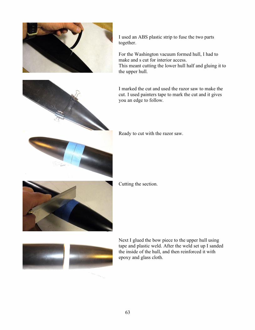
Next step I sanded the master. Filled, and then sanded with primer on the surface until smooth.

34
After a bit of buffing I added risers of thick balsa to the base of these masters. The idea here is to raise them off of the vacuum form table and create a demarcation line. Once it has been vacuum formed in ABS plastic, the builder will be able to tell where to cut off the flash and then flat sand the hull to the line.
Line is indented about 1/16 of an inch.
These masters are ready to mold, which will be explained later in the relevant chapter.

35
Making the Sail, Deck and Appendages
There are many ways of making the sail and the deck masters. RenShape is one of the best materials, but is very expensive and can only be purchased in large pieces. So I have opted to use other materials .One of those is Balsa. Blue foam is another. In some cases you can make ribs out of ABS and sheet it with more ABS
The 212 sail has so many compound curves, that I used blue foam. Using the top view on my 212 plans I was able to pick out the main cross sections that defined the basic shape. Using the top, front and side views I was able to hand shape the rest.
The Washington-class sail, before detailing. I did the same thing for the Washington class boat but used a soft balsa wood block instead of foam. The balsa worked well, plus you can get it from your hobby store.
The sail sitting on the deck, after detailing. This deck fit was achieved by tacking sand paper to an UltraCal deck form. Then the sail was flat sanded on the form to a good fit. You can always pour parts of forms you made need from your molds, anytime. It was easy using the missile deck mold to cast an UltraCal 30 form to use for sanding.
For the 212 sail I used the base cross section where the sail meets the deck and the most upper cross section, and then I did a basic wire cut.

36
I didn’t make the sail blank until after the hull was finished, to ensure a good size match. The parts need to be slightly under sized. You need to make an allowance for the material you are going to add.. Once I was content with the shape, I glassed the master in the same way I did the hull. The sail has been glassed, filled and shaped to fit the deck. Here I’ve started with some of the details and geometry that defines where the chart tape will go and the sail plans will attach. All this information was pulled from the plans and that handy Revell model.
To blend the sail to the deck I used blue painter’s tape, this protects the hull master from scratching. It was then easy to blend the sail. A little Evercoat and sanding, and then a little primer and it’s ready for detail.

37
If you have any cuts or deep recessions to make, now is the time. There is a deep cut out in the trailing edge of the 212 sail, I cut it with a razor saw. To seal the exposed blue foam I used a light coat of epoxy, then sanded it smooth and fixed any remaining problems with Evercoat.
Next I marked all the panel lines, sail planes locations, doors and hatches. I did this with pencil and then clear coated it. I used pencil rather than pen because if you make a mistake you can erase it.
For the next step I needed to have the sail planes on hand. I used thick PVC sheet that can be purchased at your local hobby store, they usually have a rack of sheet styrene, PTEG and PVC sheets. Using the plans, and studying the reference pictures, I cut and sanded the shape of the sail plane master. A flat sanding bar works best to achieve this basic shape. I marked the root and tip with the airfoil
shape. Sanding bit by bit making sure I had a straight taper from the root to the tip. The demarcation line is where the flash is removed from the molded piece. To point this master up, I used Evercoat and red putty. Then I followed that with several coats of primer.
To mold the sail plane I mounted it to a PVC shape and then to an ABS base. I sprayed silicone mold release on the master and built an ABS box around it. I then glued it together with CA and made sure I had no leaks. Next I mixed GI 1000 silicone and poured the mold.
Mold box with master inside.

38
Let the silicone set 24 hours. For best results start pouring product after the mold has had two days to air out. This insures the surface is fully cured and will extend the life of your silicone mold.
Next I cast two sail planes using Alumilite. I mixed the material 50/50 and poured into the mold. To make sure I didn’t have any bubbles I used a tampered shaped Popsicle stick and agitated the resin, tapping the mold helps too. The vibration breaks bubbles. I then determined the thickness of the filet based on the plans and model. I marked that on my sail and cut.
I did this for both sail planes. I then lightly glued the filets back to the sails. This will help in aligning the sail planes and filets as well.
My friend Olivier was kind enough to enlarge the plans and laser cut vinyl decal sheets.. This made it easy to locate the fins to their base. It also helped a great deal for other details to be added later. I attached the sail planes with a bit of epoxy. I used the 5 minute type with micro balloons. I checked to make sure I was level and straight to the table.
First both plane locations were lined up level to each other using the vinyl templates and measurements.

39
Some basic geometry drawn out on paper, just to help everything line up. Here I’ve tacked it with medium CA so I could adjust it. Then I filled in around it with epoxy and micro balloons.
Another view, ensuring the plane is horizontal.
Once the epoxy set up I was able to detach the sail plans leaving only the filet. I used a bit of Evercoat and sanded the filet to shape.
Evercoat filled in around the filet.
Top view shows the Evercoat and the even match of the two roots. Last step, was to primer the filet.

40
I added other details to the master using carved ABS strip plastic. I mounted and blended them with putty. For the two sail fairings, I carved and shaped one of the fairings. Then, using the plans I used silicone and made a quick waste mold to produce two pieces.
Styrene strips were used from the LHS. Once cut and shaped, they formed the sail fairing.
This is the finished fairing master. I only needed one, as it is the same on both sides of the sail.
Mount the master to a flat surface, build some clay around it and pour. Going back to my pre marked panel lines it was easy to line them up and glue them on.

41
Perfect! Just like Revell!
The sail is complete with the small shapes applied and sitting on an early pull GRP hull. Looks good, and now, for the further detailing.
Using chart tape and vinyl transfers I added the rest of the sail details. If you mark everything correctly with a pencil this step goes very fast.
Close up view of the work. Olivier’s transfers really help a great deal.

42
Nice and even. Not bad!
I applied several coats of primer until I could see it building up on the tape. Then removed the tape, the vinyl transfers, and lightly sanded away the ridges.
The sail is ready to mold. I added a riser to the base of the sail that demarcates the flash cut (not shown in the 3D images). I then mounted that to an ABS base and built a plastic box around it. Silicone was poured into the box and left to set up for 24 hours. Just don’t pour it but rather use a disposable brush and brush it on layer by layer. This will prevent bubbles in all those nooks and crannies. Then slowly pour in the rest.
Sail master gets mounted to a flat base.

43
An ABS styrene wall is built around the sail master. Seal this to a wood or plastic sheet base with thick CA and modeling clay. Try not to be heavy handed, as you want to break this away from the base for de molding.
The blue color is the Silicone that has been poured into the mold. A brush coat at first will helps reduce bubbles.
Here is the finished mold removed from the master. A little shifting with your hands should break free the styrene from the mold. You can leave the styrene in place for a supporting mother mold.
Since silicone is a flexible material, you must have an exterior mold to support its shape.

44
Stern Plane Masters
It was only necessary to construct one plane for the 212, since all four planes are identical. I cut the fin shape as before with the sail planes. Once I had the shape (using the Revell model as a guide) and the planes I marked the cut line that separates the actual rudder or fin from the base root. The cut for the 212 planes is the pivot point of the plane.
This is an example of a set of planes bagged up for a kit. Once I had the cut marked, I very carefully cut it on a scroll saw and then a little sanding and pointing up. I lightly glued them back together. I then put them in a drill press vice, and drilled a pivot shaft. Once the holes were drilled, I broke the bases away, and drilled out to a slightly larger diameter for the bearing.
The bearing is made of brass tubing, and the stem of it, can be seen in the picture. This stem seats in the fiber glass hull of the model later on. Fitted through the bearing and into the plane is an inside diameter sized piece of brass tubing. It is this tubing that gets glued to the inside of the plane itself and extends beyond the end of the bearing to be controlled later on. This is what allows the control arms from the WTC to move the planes.
Here is a 3D wire frame diagram illustrating the part.
Blanks for the stern planes before being sanded to shape.

45
The red line is where the shaft will be placed. It is also the pivot point.
The finished masters.
This illustrates the cast parts. The bearing is clearly shown.
Once I had a good working master I was ready to mold. The base and fin were molded separately. Before claying the masters up, I attached thin brass tubing for injection points and venting. For the base of the sail plane I pushed the bearing sized diameter brass tubing through the master with enough space left both top and bottom. This will later make a groove in both mold halves in which to lay brass tubing before I cast a part from the mold. Later this gets removed and you have the perfect sized diameter hole for the bearing.
The shaft coming from the plane itself affects the same idea. Later you have a perfectly aligned hole, from which to place the brass shaft. This allows the shaft to be permanently installed into the plane when casting resin.

46
Pictured here: a rough clay lay up of the 212 fins.
When laying up the masters in clay, use a knife to cut the sides as straight and square as possible. Then, using small sculpting tool, make sure the clay is pushed up to the very edge of the master. It should be exactly on the leading and trailing edge. It will help you a great deal, to use a pencil to mark the exact separation line. This way when laying up the clay, you can always tell where the 50/50 point is. You can smooth the clay with a bit of Vaseline and a brush.
Make round “keys” (positive and negative grooves that interlock with each other) in the clay. This is for locking the two halves of the mold together. Next make an ABS styrene box around both lay ups. Once finished you should have something that looks like this. You are now ready to brush in the silicone and to then pour in the remainder.
Here you can see I used clay for the lay up’s on the small 212 stern planes.
A styrene wall lay up. Silicone has been poured into the boxes.

47
The poured 212 stern planes mold. Pour the silicone into the mold and let it set up overnight. The next day, remove the assembly from the table, flip it over, and remove the clay. If the master pulls away from the mold or the brass, press it back in. Next, lightly Vaseline the surface of the silicone mold. Remember, silicone only sticks to one thing in life, it’s self! Vaseline works best to release it.
Place the styrene box back around the mold. Then pour the other side in silicone. This is exactly the same procedure used to make the first halve, again, let the mold set over night. Remove the styrene box and peel the two halves apart and you should have the stern plane molds perfectly.
Here are all the components used to make the stern planes laid out.

48
Making the Missile Deck
In making the deck for the Washington class boat I used Bluecore insulation foam. It can easily be purchased from a local builder supply. It comes in thin blue sheets, is quite inexpensive, and can be fashioned into a variety of shapes and sizes. Don’t forget to peel off that plastic film. You can’t sand and shape with it still Here are the pieces ready to glue together.
I used a side and top view from the plans and made cut outs in Bluecore. I bent and curved them to shape and used foam safe CA to glue them together. I then sanded to shape and filled with balsa fill. First side glued in position.
The second side in place, the deck shape is complete and ready to sand to shape.
This illustrates the under side of the Bluecore deck.
Check fit to the hull and sail, before glassing.
.

49
Satisfied with the basic shape and fit, I filled and sanded. Now she was ready to glass.
I sanded the epoxy just as I did the hull filling, until smooth and correctly shaped. Once this is done you can primer, fill sand and prime some more, until a perfect finish.
Once the surface is smooth with a coat of primer I could start the details.
This deck will also be a vacuum formed part. With the deck vacuumed formed from .030 styrene, because it’s very thin compared to the hull it will show detail. Chart tape and vinyl again was used to do this. I cut colored vinyl tape for the missile doors. After few coats of primer and a light buff, the deck is finished.
Next I added a riser made from balsa to lift the deck off the table for vacuum forming. This will show where the builder needs to cut off the flash and sand the edges.

50
To mold this piece I used the same method as I used for the sail. Build a wall around it and pour silicone. Any of these silicone molds can be used to pour UltraCal for vacuum formed plugs or lay up in glass epoxy and or resins. I mixed up UltraCal 30 and poured the material into the deck molds to produce a stone like plug to vacuum form over.
The Ultra cal has been poured and set up. This material is just like plaster except a lot harder, it won’t chip or scratch easily.
The UltraCal 30 plug can be lifted easily from the silicone mold once hardened.
For this deck mold I used UltraCal rather than glass for the mother mold. If you decide to do so, you can use this for all of the mother molds you may need. However, keep in mind that larger molds will be cumbersome and heavy. This is why for larger molds like the hull, I prefer a glass mother mold. Easier to handle and lighter too.
This picture demonstrates just how much detail UltraCal 30 will pick up. This plug is now ready to vacuum form.. The nice thing about a silicone mold is, that you can pour as many copies as you want of the plugs. This way you can pull a few at the same time. The plug gets placed on the vacuum form machine I purchased from www.customformers.com. The plastic heated and pulled over the forms, creating decks for the Washington model.
51
Making Hull Molds
Making a mold of the hull master is similar to the other type of molds I have shown you so far. The big difference is the all important parting board. The parting board is for mounting and separating the two half molds you will create. You can use just about any flat strong material. Wood with a smooth surface works well. Formica and wood shelving is another source. To start, cut a rectangular piece of wood to suit your hull. Leave plenty of space either side of the master. 4-5 inches is good. Make a copy of the top view of your plans to scale. Print it out and use 3M 77 to glue it down to the sheet of wood. Then, using a gig saw cut out the profile shape.
You should have something that looks like this. Next, wax and buff the hull master with Partall wax. With an airbrush, spray 4 coats of PVA on the surface. Place the hull in the parting board so that line you scribed earlier sits slightly above. Block in from underneath the master with clay, or wood, or anything else that will hold it in place. You will have gaps between the board and the master. Fill these with clay using a sculpting tool.
Clay lay up against the hull which fills the gaps.
The 212 was meant to be a vacuum form kit, so the riser for lifting the master off the vacuum table, was laid in, using modeling clay. However, for a glass mold, this is not needed. Here you can see the ABS box I built around the 212 hull.
Next step is to build a box around the master. You can do this with ABS or wood. Glue it down to the building board and fill the gaps with clay to prevent leaks. Angle the box as much as possible, this helps to not wasting the expensive silicone.

52
This illustrates the layers of this process.
Another angle.
It’s time to mix the silicone and then brush on a surface coat. Next fill the box with silicone and let set over night.
Pictured : The 212 mold filled with silicone. Notice the clay I used to seal any leaks. Take great care with this step. You don’t want to come back 12 hours later to see a $100 of silicone cured on the floor, very depressing.
Pictured above: A CGI version of the filled mold.

53
I’ve removed the Styrene walls in order to make a glass epoxy mother mold. Do not remove the mold from the master at this time!! You can either remove the Styrene and glass directly on to the silicone mold, or glass directly over the box, for your mother mold.
Once this has been done you can remove the entire mold from the parting board and you have the top halve of the mold. Here is the 212 mold with a glass epoxy mother mold. Cut away all that excess and sand it until smooth. Wearing disposable gloves will help prevent small shards of glass from getting in your fingers.
Remove the hull master from the board, and turn it over, and repeat the same steps for the lower half.
The 212 molds opened and ready to go.

54
There are other ways of making a mold like this. It takes more time, but wastes less materials. You can brush on silicone without a wall, using a fast setting catalyst. You just keep brushing it up until it starts to gel. It may take two coats. You can then use UltraCal or fiberglass mother mold.
David Merriman provided these images of his work, which show the finished master in the parting board. You can see the green modeling clay used to fill the gaps, and the deposable brush he used to smooth the clay to the board. Pictured here he is waxing the part board for a release agent.
Here he is pouring up the BJB mixed silicone over the master. This is a brush able silicone or RTV that he will keep located by brushing its mass at an even thickness until it gels. This will usually be followed by a second coat. You’ll notice that the RTV is clear and has few, if any bubbles. David uses a vacuum chamber to evacuate the air from the mix before making the mold, great if you have one.
Pictured here, is the epoxy system we both prefer to use. The brown stuff is one of their many types of filler they make to thicken up the epoxy for brushing on.
Brushing on the thickened epoxy gel coat over the clear RTV. This will be followed by several layers of the glass cloth.
Here you see the layers going on. This makes the mother mold that will support the shape of the RTV glove.

55
Pictured here, David’s Granddaughter Rose holding a cast epoxy glass hull section from the completed mold. This method is easy and keeps wasted materials to a minimum. Thanks for the pictures David!
What follows is the absolute best way make a case mold, unfortunately, it is a more difficult process. With your master mounted in the parting board place, place plastic wrap over the master to protect it. Then use water based clay and build up an even thickness over your master. Smooth it out by hand, using brushes and water. Water base clay can be purchased from most art supply stores. Mix up some more UltraCal 30, and make a mother mold. Tip: You can use burlap to ensure a stronger mold. First lay on a coat of stone, about ! inches thick. When it sets up and bit take strips of burlap soaked in water and make them wet with UltraCal. Lay them on to the first coat and add more UltraCal over the burlap. Make sure you have an even thickness of UltraCal and burlap making a nice flange all away around the base. You will need to drill thought this later. Smooth all this as it sets bit by bit. Let the stone set up a few hours or more. Drill some ! inches holes through the stone into the parting board. Make sure you can put bolts through the mold and into the board. Do this all away around spacing them out about 8 inches. You don’t need that many. Remove the stone mother mold and set it aside. Clean off the master and remove all the clay. Make a large 2 inch diameter hole at the highest point on the mother mold. You will pour silicone through this hole. It is important to make sure that the hole is at the highest point, so the mold fills evenly. It might even be necessary to have more than one hole depending on the shape of the mold. A second hole can always be plugged up with clay during the filling. It’s important to get the trapped air out of the mold. Put back the mother mold and bolt it down to the parting board. You can now pour your silicone. This method wastes nothing and uses only the silicone needed to do the job.

56
For the Washington molds I used UltraCal 30 and burlap for the mother molds. The molds you see are the top and bottom hull. The deck and two tail cones, dive planes, rudder, and sail planes. This has explained the basics for mold making. You can make short cuts or be more elaborate if you like. Either way you should have a grasp of how to make a mold from that shape you spent all those weeks or months on. Now you can make more, and you can build your own model. To fulfill a request of Mr.Merriman I have been asked to print the statement below, and of course I support his opinion. "Please, take all the information I've shown you on tool making and use those skills only to make copies from your own masters. Do not use these techniques to make unauthorized reproductions off of other peoples work! Such conduct is called, 'stealing'." "You wish to make tools and parts off someone else's work? Fine! Secure from them permission before doing so! I don't care if it's just a single item for 'your own use’; don't reproduce someone else's work without the owners permission!" "If you are such a talent less, stupid, dope as to need to copy other peoples work, then may I suggest you would be more comfortable knocking down old ladies at the mall and running off with their purse; or maybe stealing candy from kids -- an activity more in keeping with your moral code and sense of fair play." “I’m teaching you how to make masters, pulling tools from them, and then using those tools to make copies of your work. I'm not teaching you this shit so you can steal from others. Don't be a selfish, rude, thieving moron! Be a Model Builder." How's that, Steve?
Perfect David! Thanks!

57
Casting Resin Parts
Planes, fins and small parts I have a simple method for casting resin parts using gravity and pouring the resin into an open ended mold. Let it set up and remove the part, be careful, bubbles can result. Agitating the inside of the mold and resin with a stir stick can help prevent this. Placing the mold on a vibrator can also help. Remember, you can always fill small bubbles.
I found that works great to inject the resin through a small syringe. The stern plane molds for the 212 are a good example. There is an injection hole for the syringe and a bleed hole for the venting of resin.
When you inject the resin it will start coming out the vent hole and you will see bubbles. Wearing rubber gloves, I place my thumb over the hole and keep injecting until it builds up pressure inside. This causes pressure inside the mold that will crush the air bubbles. When some leakage occurs at the seams, it’s time to stop injecting the resin. Remove the syringe and set the mold aside to set up. I get perfect parts every time with a minimum of bubbles using this method.
The Washington stern planes molds. The right and left halves are seated on their ABS boards. The rubber bands are for holding them together and the injection syringe was purchased from my hobby store. ABS support boards placed in position and rubber bands holding them together.
The syringe is in place, ready to inject the resin. Never push the plunger down all the way or you will inject bubbles. To make it nearly bubble proof a pressure pot can be used, if you own one of course. After injecting the resin place the molds into the pot and pressurize.

58
Casting the sail
To cast the sail I use an open ended mold. I learned long ago you could slush this material around the inside of the mold and get an even thickness that is still very light. It takes practice, and works best in low temperatures of 68 – 70 degrees, the resin sets slower. You simply mix up the resin pour it in and hand rotate, turning the mold evenly to coat the inside surface.
This is done over and over until you can actually see the resin thickening. Then, “up end” the mold and let the excess resin run out. Do this a second time and you have a very light even part, bubble free too.
You can also make the sail from glass epoxy if you have trouble slush pouring.

59
Props, Fittings, Mast and Scopes
Many of these parts can be made with scrap from around the house and shop. Pens, brass tubing, styrene strips, rounds and squares from the hobby shop work well enough. Parts from plastic kits you may have lying around can also be useful. Be creative. If you have a small modelers lathe you can turn your own shapes from stock brass, aluminum and more. It is possible to make the propeller yourself. There are many good articles in RC boating magazines that illustrate the process. David Merriman’s Cabal reports on www.subpirates.com are some of the very best examples of how to make your own prop. For most subs you can use ones that are commercially sold. Just do a search on the net and you will find lots of sources shapes and sizes. Many of the parts I use on my boats are made custom by David Merriman. It is possible to make part masters shapes from styrene, metal or other materials and make silicone molds of the parts in which to produce resin cast parts. In order to pursue metal casting, you will need to invest in a centrifuge, melting pot and metal casting tool.
Metal casting is another way to make custom props and other parts. Here is an array of parts both metal and resin, made by David Merriman, for the 212 kit.
For this and other sub making instructions go to: www.subpirates.com Go to David Merriman’s Cabal reports section and read up!
60
Building the Boat
Now that all the parts are made, it’s time to put the boat together and make it a good running RC model.
First, start with the hull, trim the flash off to the demarcation line, I use scissors. This works on both ABS and Epoxy. If your hull is really thick use a dremel tool and a cut off wheel.
Next make up a flat sanding board. You can do this with a very flat and true plywood board as I have shown here. It’s very important that this board is truly level; otherwise it will result in two poorly fitted halves. I used 80 grit wet dry sand paper and 3M 77 to stick it down.
Place the trimmed hull halve on the board, and with a slight pressure start to flat sand it slowly, stopping many times along the way to check the edge. If you press too hard the sides of the hull will spread and this will give you uneven flat sand. Just light pressure and check. Once you have sanded to the line, the part is finished.
Next, flat sand the other half and start checking the fit to each other. If your boat has tail cones use the same procedure. Once you have all these parts flat sanded and fitted, you can now put the hull together. Tape them together for a final check.
Above, I have flat sanded the sail to fit on the form that I made earlier on. I cut the deck out with scissors and sanded the edges to shape. Then taped it all together to see how it all fits making minor adjustments.

61
The 212 hull cut, flat sanded and fitted perfectly.
Before going any further check how the WTC fits the hull before making any determination of how to cut it, to make the WTC accessible.
Battery compartment fits snug to the 212 bow.
With the top closed you can see the WTC fits properly, nice and snug. With this hull I opted to cut the stern at the tail cone.
I made an even cut line using the surface tool.

62
I used a razor saw to cut it. You can purchase a razor saw from most hobby stores. I glued this piece to the bottom section of the stern with epoxy, using some glass reinforcement from the inside.
What you see here are the beginnings of the index, made out of ABS. You can use glass strips as well. You don’t need much rise from the actual edge of the hull, an 1/8 inch will do. Anymore than that will distort the round of the hull and result in a bad fit.
Sand the glass and or epoxy where the strips will be placed, sand the strips as well. On the 212 I used CA to lock these down. With ABS to ABS, use the plastic weld glue; this is made for styrene models you can get it from the hobby store.
For the Washington class boat used the same techniques. I needed to join the tail cone since it was made as a separate piece. I drew an outline of the hull on paper found the center line and lined it up and the cone for a good fit
It is only necessary to do this step once, as once the cone in is place, the other half will just naturally line up. Lightly tack the cone in place with CA. Be sure always to sand and rough up the areas to be reinforced and or glued together.
63
I used an ABS plastic strip to fuse the two parts together. For the Washington vacuum formed hull, I had to make and s cut for interior access. This meant cutting the lower hull half and gluing it to the upper hull.
I marked the cut and used the razor saw to make the cut. I used painters tape to mark the cut and it gives you an edge to follow.
Ready to cut with the razor saw.
Cutting the section.
Next I glued the bow piece to the upper hull using tape and plastic weld. After the weld set up I sanded the inside of the hull, and then reinforced it with epoxy and glass cloth.

64
The inside along the seams is roughed up with 80 grit sand paper.
Shown here is the glass reinforcement in place.
The end result. The tail cone upper section is not glued to the bottom until the linkages for the dive planes and rudders are in place. It’s important to index the lower hull at the bow section to the bow cut. This is done using ABS strips and plastic weld. If the WTC fits well, it’s time to hook it up to the hull and get it running.

65
I made the bulkheads for the Washington from resin, using silicone molds. Then mounted them to the WTC, and glued them to the inside of the hull. First I located the bulkhead positions and sanded. I then lightly tacked down the bulkheads at their centers. Not the sides. If you force glue bulkheads to the hull it is possible to distort its shape.
Bulkheads are tack glued with medium CA.
I used a flat balsa building board to lay the two sections down. Then pinned two strips of hard straight balsa on both sides, being careful not to distort the shape.
The bulkhead area in this hull is straight and linear. This was an easy way to lock in the correct radius of this hull. I lifted the section out. Mixed up epoxy and micro balloons and coated the gaps and sides of the bulkheads. I then placed the hull section back on the building board to dry. The thickened epoxy fills the gaps and properly connects the bulkheads to the hull without distortion. Once it sets up, it’s time to mount the WTC.
The WTC rests well in the bulkheads. There are many ways to hold it from floating away. Rubber bands are common. To do this, epoxy in some hooks either side of the WTC and stretch the rubber bands over it. For the Washington, I made a brass strip that I bent around the WTC and attached to the bulkheads by two screws. The two strips of ABS glued to the WTC keep it from moving back and forth.

66
Now that the WTC is fitted, it’s time to move on to the assembly of the rudders and dive planes. Starting with the rudders, I located its pivot point. I marked the location and drilled 3/32 shaft holes on a drill press.
I glued, using epoxy, the brass shafts into the rudders. Depending on the sub you build, be sure to place any fin or rudder in its proper location on the hull. Then make a measurement that will give you and idea of how long the shaft needs to be. You can always cut it shorter later on.
Take the two parts, check their fit, and correct them accordingly. Using a drill press, drill a 3/32 shaft through the dive plane to later accept the control shaft and hinge.
The Washington had hinges for the planes that extended from the TE of the fin deep into the dive plane. I marked the location and cut a slot into both the plane and the fin. I made the hinge out of sheet ABS and glued it to the fin. The dive plane is fitted to the fin and drilled. I drilled through the shaft pass the hinge, and out the root of the fin using the drill press.
The hinge for the pivot shaft needed to be rounded off using sand paper. This will allow the plane to rotate smoothly on the hinge and inside the actual plane itself.

67
Next I tapped the 3/32 brass shaft through the drilled shaft, the hinge, and the outside of the root.
After the hinge has established good rotation, the assembly can be taken apart, cleaned up and made ready to accept the paint. To make a simple control arm to move the shaft I used model airplane wheel collars and brass flat stock.
Grind or file the plating from the wheel collars, as they are brass. This will enable the solder to fuse to the wheel collar. Drill pilot holes through the brass. This is where the control shaft from the WTC will later connect. Grind the control arm (or bell crank) to a taper around the connecting hole, and at the base where it will be connected the wheel collar. Don’t forget to drill a 3/23 hole for the dive plane shaft to exit. Attach this part with silver solder.
Now you have a serviceable control arm that can be adjusted.
Repeat the same steps for the other dive plane.

68
Locating the exact position to the dive planes is next. Using the plans and measurements mark the position of the plane and the shaft. Then drill out a half moon in the stern to clear the shaft. Do this on the upper half of the stern cone too.
Lining up the dive plane to the stern to mark the location of the shaft before carving the slot. Since the hull parting line is exactly level, it’s only necessary make the dive planes level to it. Because there is a leading and trailing edge this is made easy by lining up the TE and LE to this line.
I tacked the planes in position using medium CA, just use enough to hold it and still flex it. Because the CA sets slowly, it allowed me the time to position the dive planes in their correct and level positions.
Checking for a level fit. To get both planes to be level to the table, I squared up the hull and using a Popsicle stick and a level made sure I had no anhedral or dihedral. Thick CA dries slowly, allowing you the time to adjust, while still holding the piece. . Once you have it all lined up straight, you can epoxy these planes permanently.
Fill in all around the bottom of the plane with epoxy thickened with micro balloons. This was only done on the bottom, until the top of the stern cone is glued in place later on.

69
The Washington class rudders are one piece with a control shaft and bearing in the hull. Locate and mark the exact location of the rudders pivot point. Drill a hole for the shaft and bearing. This bearing is cut from brass tubing, the inside diameter fits the rudder shaft. Fit the shaft and bearing through the hole and tape or tack glue the entire assembly to the hull, making sure it’s true.
I used a piece of tape and marked the location.
To give the bearing some more load area, and strength, puddle up a bit of epoxy and micro balloons. Make sure and rough up the outside of the bearing with sand paper and glue to the stern. The rudder shaft should turn smoothly inside the bearing. Repeat this for the other half. Build two control arms the same way as was used for the dive planes. Then install the bottom rudder and control arm.
Rudder control arm in place.
Before I can close this up I have to install the drive shaft components. With this particular boat it makes it easier to connect the Z bends that move the shafts. It’s very cramped and has limited space back there.

70
I used a 1/8 brass tube for my prop shaft. With the WTC in place measure the length of the shaft needed and cut. You must account for the for the dog bone coupler seen in the far right. A center support load bearing was added with a brass bearing and two wheel collars either side. This keeps the prop shaft from backing out of the dog bone.
At the far left is the Oilite bearing with a 1/8 ID. To create more surface area, with which to glue the bearing to, I used plumber’s repair epoxy putty. This stuff comes in a stick and looks like a tootsie roll. Break off a piece and fold it over and over again with your fingers until the light gray and dark gray mix. This mixes the base and catalyst together. Place it under the bearing and form it like clay, It won’t stick well to the bearing so after it hardens you can break it loose and epoxy it in place permanently.
Using 1/8th brass rod, cut the control rods to length. Flatten them on the ends and mount an RC airplane ball and socket, which would attach to the WTC. On the opposite end use Brass wire and make a Y on both control arms. The wire was formed into a Z bend and put through the holes in the bell cranks.
Make up the control rods that attach to the WTC control shaft ends, and also to the planes themselves. The Z bend should fit, and appear as it does on the right side in this picture. The one on the left had to be adjusted. The less play the better.
With three of the Z bends connected to the lower hull, the top rudder remains. Hook up the last Z bend to the rudder bell crank, and then glue the cone and hull together with epoxy.

71
Fill in more epoxy and micro balloons around the dive planes. I added index strips and mounted the sail to the deck with screws. Then I attached the sail to the deck and both to the upper hull. I then checked against the plans for proper locations and alignments. ABS thick strips were used to make mounts in the deck and the sail, from which to screw into.
Here are the indexing tabs which lock the hull together.
Here you see the simple ABS sheet that was used to bolt the deck on.
The sail location was marked and the holes drilled to vent air and water. The two plates of styrene are visible. The sail planes were attached to a brass shaft. One end gets a glued on fin and opposite end of the shaft is pushed through the two aligned holes to the other side of the sail. You can then glue and align the opposite sail plane.
The sail was attached to the deck in its proper location and drilled through from the bottom of the sail. Screws were then tapped in. Then using the same method the deck was mounted to the hull.

72
Hey, it’s starting to look like a boat! The top half of the hull is held in place by a single screw.
For the Washington, I used two more additional screws on either side of the hull. With such a long parting line on this boat it would flex under load, so the additional screws prevent this. Necessary, though they can be annoying to remove.
Now that everything is in place, it is time to drill and cut vents. Quite simply, the boat won’t dive or surface well without them, because air gets trapped in the boat. When diving, you want that hull to fill up evenly with water. I used the Skipjack plans to locate the drain holes on the Washington. Since few information details exist on the drains, this seemed the correct thing to do. Especially considering that the Washington was made from a Skip jack hull, with a 139 foot missile section added. I started with pencil and marked the locations. Then using a drill, I drilled large holes inside my marks, using an Exacto blade and files to do the rest.
Next I located the actual vents on the top side and drilled round holes to vent the trapped air. In addition I added taped details to the deck, based once again on the Skipjack references I had. I was able to use both plans and pictures.
Pictured here, are the finished vents. The sail has had its bridge cut out and a few holes to mount the masts and antenna, all made from brass tubing.

73
Rear vents in place.
This is looking great. Vent holes were added to the deck dead center of the missile hatches.
Time for the base paint. I mixed black and white enamels together to get a very dark gray. Subs are not jet black. I then airbrushed the dark gray on the top side only. For the anti foul I masked off the deck at the water line. I was able to do this using that all important surface tool. Then I used Kyrlon’s Ruddy Red primer which is a near perfect match to anti foul, straight out of a spray can.
The hull is now ready to start weathering. I used a combination of materials. Water color pencils, pastels, an airbrush, and enamel paints. Be sure to use small brushes. There is some very good information on this subject available from The Cabal Report and accessible through www.subpirates.com. These are posted by David Merriman, and can be invaluable.
Remember, if you are new to this hobby, (my wife says obsession) be sure to do all kinds of tests. Test your technique and develop it on scrap pieces. Study pictures of real subs. They can be quite dirty with every thing from bird poo to algae scum lines at the water line when they sit docked in harbor.

74
With the basic weathering finished I could apply the decals. To make the 598 numbers I used Woodland Scenic’s dry transfers. It seems as though all art supply and hobby stores seem to carry. They come in all types of fonts, sizes, and apply easily. They have the look of being painted on.
Once you’re done with all the weathering you can clear coat the entire boat in Model Master Lacquer overcoat. This will seal in the weathering and protect the decals from the elements.
Looking good. And how about that wonderful clean seam line?
You can just see the drain holes. This sub is done.

75
Trimming The Boat
Trimming the boat is just a matter of getting enough ballast and foam installed inside the sub. It should be trimmed to the proper Center of Gravity, both under the water both and on the surface. Where you put the ballast weight and foam is directly related to the sub’s distribution of weight of the hull, volume of the WTC, and it’s placement in the hull. Put the boat into the water with the ballast tanks full. I let the hull fill with water and see how she sits. Sometimes they will lean to one side like a dead fish.
To correct this you need to place lead weights at the very bottom of the hull. Now that she sits up right you may find she either hangs by her stern or her bow. To correct this try shift the position of the lead until she sits level. If she sits level but is not at the true water line, you need to cut up some pieces of blue foam and place them inside the hull both fore and aft. Then you will reach the correct water line . Glue the foam in with silicone sealant .
If the boat submerges it should not go any deeper than the top of the sail. If you ever have a problem and lose power or signal this will help as another form of fail safe because she will always come back up to top of sail height. Testing your boat at the lake, you will be able to see your sail and retrieve the boat. With some boats it will take a bit of time, depending on their configuration, to get this right.
Under water the boat should also sit level at the CG when standing still and hovering. Here is the boat properly trimmed. If the bow or tail hangs, then you need to go back and make adjustments until she is level. Then check on the surface again and check how she sits on the surface. Nose down? Needs either foam in the bow or weight in the stern?
It might take several tries before it’s to your liking. Now glue and lock all your lead and foam in place. You are ready to run the boat!

76
Running the Boat
Before you run your boat it’s important to lube the seals with silicone oil or silicone grease. A little drop on the seal will do. Move the controls back and forth so the oil gets in the seal, this helps to preserve the seal against any possible leaks. You don’t want even the slightest amount of haze inside the WTC
Running your new boat is much like an RC model in the sense that the gimbals on your radio control the functions. Turn on your radio, install the battery, close up the boat and you are ready to go.
The right stick is moved back and forward controlling the pitch of the boat. Up elevator, if you look you can see the servo arms moving the control rods.
Down elevator, pushing forward dives and pulling back, pitches the bow upward.
.

77
Moving the right stick to the left and right, turns the boat.
The right stick controls the throttle by pushing forward and back. Neutral is motor off.
Prop running The right stick moves left to right and this controls the valve to your ballast tank. Move it to the right and the servo opens the flood valve to flood the tank. Move it to the left and this releases gas or air into the tank and raises the boat to the surface or somewhere in between to hover at a certain depth. You can move forward and slowly flood the tank for a nice scale dive. Or you can dive in place, give it power and go under. There are many other functions a boat can have. Subs can shoot torpedoes. You can move the scope up and down. You can fire missiles and turn lights off and on. I have given you the basics and the rest is up to your imagination and learned skills.

78
The Basics of Vacuum Forming
Vacuum forming uses a variety of plastic sheet materials from ABS to Lexan. These materials can be heated to a temperature where they become very pliable and can be formed over just about any kind of shape. The basic vacuum form machine, either home made or purchased, consists of a hallow six sided box. The box is usually made of plywood. It is also sealed from air leaks. The top of the box will have a number of concentric holes drilled evenly through the top. A circular opening is made on the side to accommodate a shop-vac hose. When a shop-vac is hooked up to the vacuum form box it will draw air through the holes creating suction. A tray is built to fit the outside diameter of the box. Built from wood or aluminum this tray is used to attach a cut piece of plastic sheet. Clips work good to hold the plastic in place. This tray can be placed in an oven or over a heating element and heated until it just begins to sag evenly. With a form on the vacuum box such as a half sphere you can slam down the tray with the heated plastic and turn on the shop-vac. This pulls the plastic over the form and flat to the table making a copy of your form. Pretty simple huh? Yet ingenious! No laying up epoxy, casting resin, just a nice clean shape.
Here is my own vacuum form machine. Front and center is the vacuum box. The shop-vac hose is visible. The Washington class hull form in place ready to pull plastic over. The form is made from Ultracal 30, a very hard tool stone (or plaster) that mixes with water can be poured into the molds. You can also use resins such as Alumilite to make the same forms since those silicone molds you made will cast up just about anything you can mix and pour.
Behind the vacuum form box is the heating tray made from heating elements that plug directly into AC current. The frame you see resting on the heating tray will hold the plastic in place.
The plastic is in place and held by the clips seen here. It has just started to heat. After a minute or so the plastic will sag evenly and smooth. Experimentation will give you an idea just how much sag you will need to pull a good piece. Every shape is different. If it’s quite high off the table you’ll need to heat the plastic more. If it’s a shallow draft use less heating. It just takes practice to get a feel for it.

79
Once the plastic is heated correctly this whole tray is hinged and will swing over from the heating tray to the box and seal. The shop-vac is turned on at this time and it draws the plastic over the form and flat to the table.
The piece is allowed to cool. Once cool it is removed from the machine and the form. You can easily make a vacuum form machine yourself from plywood. Use a shop-vac. Make a frame from hardwood or aluminum to hold the plastic in place. You don’t have to hinge it either.
For years I had a smaller vacuum form machine that used a tray I placed in the oven to heat the plastic. I would remove it from the oven and place it over the form and turn on the shop-vac. You will not need a heating tray if you build one this way, but you are limited to the size of your oven, which can be a draw back if you plan a larger model. If you do a Google search you will find numerous sites that tell you how to build your own machine. Some will sell you plans and a bill of materials. Vacuum Forming is a good way to make a lot of different models besides submarines. Just use your imagination!
Conclusion
In this book I have given you the basic tools and concepts to enable you to build your own working submarine. Most of my attention was focused on the construction of your own scratch built hull and

80
parts. From here you can further research the equipment, tools, water tight cylinders and techniques available on the net. There is a wealth of information at www.subcommitte.com and at my own sub site, www.subpirates.com. There is a lot of detail and science I did not explore in this book. It is possible to get quite technical, and go quite far in this hobby. My aim was to give you the basics and get you started without having to wade through a 500 page book. I hope that you have learned enough to consider starting your own project, as you now understand the basic concepts and principles. If you feel that you have, congratulations, you are on your way to participating in a very unique field that will be sure to wow the boaters and spectators at your local pond or pool. I have been fascinated with this subject for a long time now, and have made it my business to learn much from the great ones involved with it. Just about anything you see can be made using the techniques as described in this book. From an airplane, to a jet, a car, sub or Sci-Fi model, all can be made. It need not be radio controlled if you like static display models these methods will allow you to make your dream model come true. I hope I have imparted to you the basics of model scratch construction using basic tools and items from the hobby store and hardware store. It will take practice on your part, but the end will always justify the means, trial and error. No two models are the same. Make tests. Get used to your materials and how they are best utilized. Talk to the many experts on line in the forums. Also if you’re really serious about this hobby, join The Sub Committee and Subpirates. www.subcommittee.com and www.subpirates.com You will meet many talented people there that will be glad to addict you to the world of model submarines. Finally after your task is complete, don’t forget to have that all important cuppa tea with the wife. It makes them think that you really didn’t forget about them while you were modeling. End