model ec 25e / ac1-ph55-08h technical · features before resuming operation of this compressor. 3....
TRANSCRIPT
- 1 -
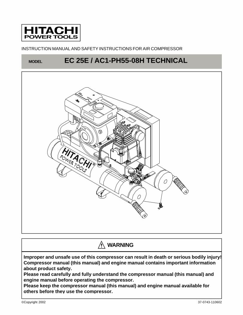
INSTRUCTION MANUAL AND SAFETY INSTRUCTIONS FOR AIR COMPRESSOR
MODEL EC 25E / AC1-PH55-08H TECHNICAL
WARNING
Improper and unsafe use of this compressor can result in death or serious bodily injury!Compressor manual (this manual) and engine manual contains important informationabout product safety.Please read carefully and fully understand the compressor manual (this manual) andengine manual before operating the compressor.Please keep the compressor manual (this manual) and engine manual available forothers before they use the compressor.
37-0743-110602©Copyright 2002
- 2 -
PageIMPORTANT INFORMATION ............................................ 3MEANINGS OF SIGNAL WORDS ..................................... 3
SAFETYIMPORTANT SAFETY INSTRUCTIONSFOR USE OF THE COMPRESSOR ................................. 4REPLACEMENT PARTS................................................... 6
PageOPERATION AND MAINTENANCE
NAME OF PARTS ................................................... 7SPECIFICATIONS .................................................. 8APPLICATIONS ...................................................... 8PRIOR TO OPERATION ........................................ 8OPERATION .......................................................... 9MAINTENANCE .................................................... 10SERVICE AND REPAIRS ..................................... 11PARTS LIST ......................................................... 12
- CONTENTS -English
- 3 -
IMPORTANT INFORMATION
Read and understand all of the operating instructions, safety precautions and warnings in the Instruction Manual beforeoperating or maintaining this compressor.
Most accidents that result from compressor operation and maintenance are caused by the failure to observe basic safetyprecautions. An accident can be avoided by recognizing a potentially hazardous situation beforehand, and by observingappropriate safety procedures.
Basic safety precautions are outlined in the “SAFETY” section of this Instruction Manual and in the sections which containthe operation and maintenance instructions.
Hazards that must be avoided to prevent bodily injury or machine damage are identified by WARNINGS on the compressorand in this Instruction Manual.
Never use this compressor in a manner that has not been specifically recommended by HITACHI.
MEANINGS OF SIGNAL WORDS
WARNING indicates a potentially hazardous situation which, if ignored, could result in serious personal injury.
CAUTION indicates a hazardous situation which, if ignored, could result moderate personal injury, or could cause machinedamage.
NOTE emphasizes essential information.
English
- 4 -
English
SAFETYIMPORTANT SAFETY INSTRUCTIONS
FOR USE OF THE COMPRESSOR
WARNING: Death or serious bodily injury could result from improper or unsafe use of this compressor.To avoid these risks, follow these basic safety instructions:
READ ALL INSTRUCTIONS
1. NEVER TOUCH MOVING PARTS.Never place your hands, fingers or other body parts nearthis compressor’s moving parts.
2. NEVER OPERATE WITHOUT ALL GUARDS INPLACE.Never operate this compressor without any guards orsafety features in place and in proper working condition. Ifmaintenance or servicing requires the removal of guard orsafety features, be sure to replace the guard or safetyfeatures before resuming operation of this compressor.
3. ALWAYS WEAR EYE PROTECTION.Always wear safety goggles approved by Ansi or equivalenteye protection. Compressed air must never be aimed atanyone or any part of the body.
4. PROTECT YOURSELF AGAINST ELECTRIC SHOCK.Don't expose this compressor to rain. Never operate thiscompressor in damp or wet locations.
5. STOP THE ENGINE.Always stop the engine and pull out the spark plug cap toprevent any sudden start of the engine and remove thecompressed air from the air tank before servicing,inspecting, maintaining, cleaning, replacing or checkingany parts.
6. STORE COMPRESSOR PROPERLY.When not in use, this compressor should be stored in adry place. Keep out of reach of children. Lock-out thestorage area.Do not store this compressor near an open flame or anyequipment such as a stove, furnace, water heater, etc.which utilizes a pilot light or sparking device.
7. KEEP WORK AREA CLEAN.Cluttered areas invite injuries. Always clear all work areas ofunnecessary tools, debris, furniture, etc.
8. CONSIDER WORK AREA ENVIRONMENT.Don’t expose this compressor to rain. Don’t use thiscompressor in damp or wet locations. Keep workarea well lit and well ventilated. Operate thiscompressor at a stable place all the time.Do not operate in flammable environment. Thiscompressor produces sparks during operation.Never use this compressor in site containinglacquer, paint, benzine, thinner, gasoline, gases,adhesive agents, and other materials which arecombustible or explosive.This compressor contains some component partsthat tend to produce arcs or sparks, and therefore,when located in a garage, it should be in a room orenclosure provided for this purpose, and should be18 inches (457 mm) or more above the floor.A spark arrester must be added to the muffler of thisengine if it is to be used on any forest covered, brushcovered or grass covered unimproved land. Thearrester must be maintained in effective workingcondition by the operator.Gasoline engines produce carbon monoxide; apoisonous odorless gas which may cause death.Do not start or operate this compressor in anenclosed area.Operate this compressor at least 12 inches awayfrom any wall or obstruction.
9. KEEP VISITORS AWAY.All visitors should be kept safely away from workarea.
10. DRESS PROPERLY.Do not wear loose clothing or jewelry. They can becaught in moving parts.Wear protective hair covering to contain long hair.
11. STAY ALERT.Watch what you are doing. Use common sense. Donot operate this compressor when you are tired.This compressor should never be used by you if youare under the influence of alcohol, drugs ormedication that makes you drowsy.
- 5 -
English
12. CHECK DAMAGED PARTS AND AIR LEAK.Before further use of this compressor, guard or otherparts should be carefully checked to see that it willoperate properly and perform its intended function.Check alignment of moving parts, binding of movingparts, breakage of parts, mounting, air leak, and anyother conditions that may affect its operation.A guard or other part that is damaged should beproperly repaired or replaced by an authorized servicecenter.Have defective pilot valve replaced by authorized servicecenter.Do not use this compressor if engine switch does notturn it on and off.
13. NEVER USE THIS COMPRESSOR FORAPPLICATIONS OTHER THAN THOSESPECIFIED.Never use this compressor for applications other thanthose specified in the Instruction Manual.Never use compressed air for breathing or respiration.
14. HANDLE THIS COMPRESSOR CORRECTLY.Operate this compressor according to the instructionsprovided herein. Never allow this compressor to beoperated by children, individuals unfamiliar with itsoperation or unauthorized personnel.
15. KEEP ALL SCREWS, BOLTS AND COVERSTIGHTLY IN PLACE.Keep all screws, bolts, and covers tightly mounted.Check their conditions periodically.
16. NEVER USE A COMPRESSOR WHICH ISDEFECTIVE OR OPERATING ABNORMALLY.If this compressor appears to be operating unusually,making strange noises, or otherwise appears defective,stop using it immediately and arrange for repairs by aHitachi authorized service center.
17. DO NOT WIPE PLASTIC PARTS WITH SOLVENT.Solvents such as gasoline, thinner, benzine, carbontetrachloride, and alcohol may damage and crackplastic parts. Do not wipe plastic parts on thiscompressor with such solvents. Wipe plastic parts witha soft cloth lightly dampened with soapy water and drythoroughly.
18. USE ONLY GENUINE HITACHI REPLACEMENTPARTS.Replacement parts not manufactured by Hitachi mayvoid your warranty and can lead to malfunction, causinginjuries. Genuine Hitachi parts are available from yourdealer.
19. DO NOT MODIFY THIS COMPRESSOR.Do not modify this compressor.Do not operate at pressure or speed in excess ofmanufacturer’s recommendations.Always contact the Hitachi authorized service centerfor any repairs. Unauthorized modification mayimpair this compressor's performance and result inaccident or bodly injury.
20. TURN OFF THE ENGINE SWITCH WHEN THISCOMPRESSOR IS NOT USED.When this compressor is not used, push the knob ofthe engine switch OFF and open the drain cock todischarge the compressed air from the air tank.
21. NEVER TOUCH HOT SURFACE.To reduce the risk of burns, never allow any part ofyour body or other materials to contact with anyexposed metal parts on this compressor.Never allow any part of your body to contact theengine muffler or adjacent areas.These areas can remain hot for at least 45 minutesafter this compressor is shutdown. Cool down beforeservicing.
22. DO NOT DIRECT AIR STREAM AT BODY.Do not direct air stream at persons or animals, toavoid any bodily injury.
23. DRAIN TANK.Discharge the drain after each use and every day.When the tank gets corroded, there can be a risk ofbreakdown. Accordingly, be sure to discharge thedrain inside the tank after each use. The draincontains moisture in the air, abrasion particles, rust,etc. To discharge the drain, therefore, gradually openthe drain cock, and be careful not to point it at yourface or eyes.
24. USE ONLY RECOMMENDED AIR HANDLINGPARTS ACCEPTABLE FOR PRESSURE NOTLESS THAN 125 PSI (8.6 BAR)Risk of bursting. Use only recommended air handlingparts acceptable for pressures not less than 125 psi(8.6 bar).
25. SEE TO IT THAT FUEL IS SUPPLIEDAPPROPRIATELY.Follow all fueling instructions in operator’s manual.Do not smoke while fueling.Do not fill fuel tank while this compressor is runningor hot. Allow this compressor and engine to cooldown for two minutes before refueling.Do not refuel indoors or in a poorly ventilated area.Do not fill fuel tank to point of overflowing.Always refuel slowly to avoid the possibility of spilledfuel which may cause a fire.Do not operate this compressor if gasoline is spilled.Wipe this compressor clean and move it away from thespill. Avoid creating any ignition until the gasoline hasevaporated. Allow approximately 1/4" of tank space forfuel expansion.
- 6 -
English
26. BE CAREFUL NOT TO TRIP OVER OR DROP THECOMPRESSOR DURING TRANSPORT.Exercise utmost caution when you carry thiscompressor. If you trip over something and drop it, thereis a fear that unexpected injury may result. If you dropthis compressor or bump it against any objects, air tankor any component parts can cause serious deformation,damage, severe scratches and breakdown on thiscompressor. If operated under such conditions, it canresult in any accidents of bodily injuries by explosion oftank or explosion of those damaged component parts.Furthermore, gasoline which spilled out by thosedamages, may have a great risk of a fire.
When there is any deformation and damage on thehandle, it may drop during transport, resulting in aaccident of injury.Before carrying this compressor, switch off the engineand discharge the drain inside the air tank.Be cautious enough to make sure that there are noobstacles, inflammable articles, and unauthorizedpeople around this compressor.
REPLACEMENT PARTS
When servicing use only genuine replacement parts.Repairs should be conducted only by a Hitachi authorized service center.
SAVE THESE INSTRUCTIONSAND
MAKE THEM AVAILABLE TOOTHER USERS OF THIS TOOL!
- 7 -
English
OPERATION AND MAINTENANCENOTE:
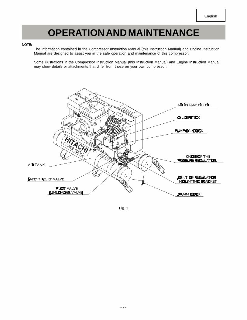
The information contained in the Compressor Instruction Manual (this Instruction Manual) and Engine InstructionManual are designed to assist you in the safe operation and maintenance of this compressor.
Some illustrations in the Compressor Instruction Manual (this Instruction Manual) and Engine Instruction Manualmay show details or attachments that differ from those on your own compressor.
Fig. 1
- 8 -
English
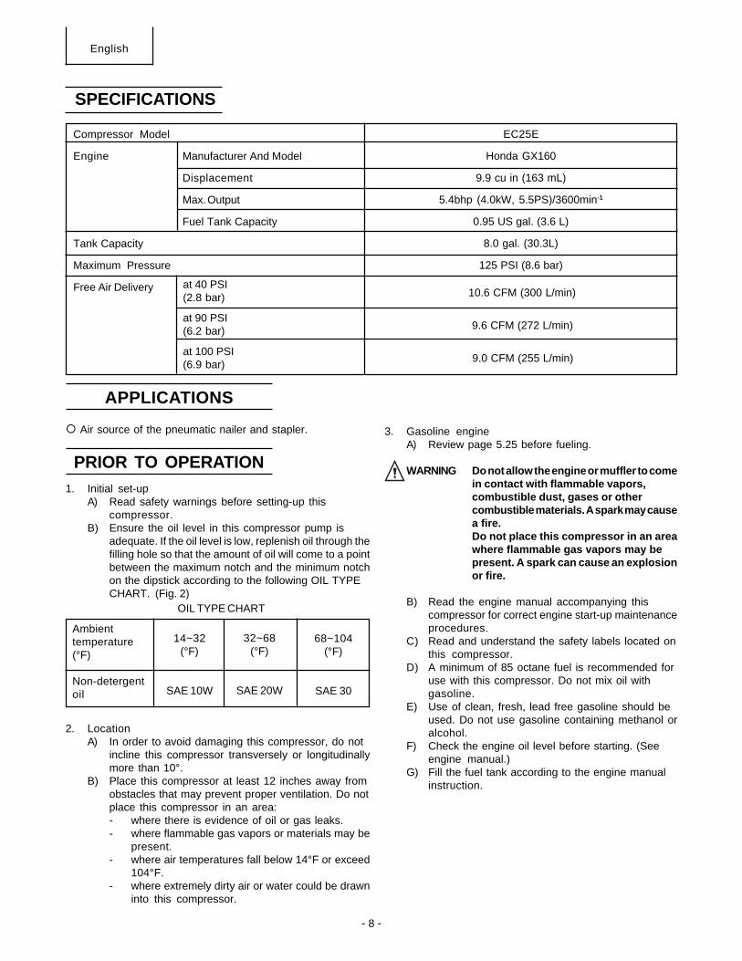
SPECIFICATIONS
Compressor Model
Engine Manufacturer And Model
Displacement
Max. Output
Fuel Tank Capacity
Tank Capacity
Maximum Pressure
Free Air Delivery
EC25E
Honda GX160
9.9 cu in (163 mL)
5.4bhp (4.0kW, 5.5PS)/3600min-1
0.95 US gal. (3.6 L)
8.0 gal. (30.3L)
125 PSI (8.6 bar)
at 40 PSI(2.8 bar)
at 90 PSI(6.2 bar)
at 100 PSI(6.9 bar)
APPLICATIONS
Air source of the pneumatic nailer and stapler.
PRIOR TO OPERATION1. Initial set-up
A) Read safety warnings before setting-up thiscompressor.
B) Ensure the oil level in this compressor pump isadequate. If the oil level is low, replenish oil through thefilling hole so that the amount of oil will come to a pointbetween the maximum notch and the minimum notchon the dipstick according to the following OIL TYPECHART. (Fig. 2)
2. LocationA) In order to avoid damaging this compressor, do not
incline this compressor transversely or longitudinallymore than 10°.
B) Place this compressor at least 12 inches away fromobstacles that may prevent proper ventilation. Do notplace this compressor in an area:- where there is evidence of oil or gas leaks.- where flammable gas vapors or materials may be
present.- where air temperatures fall below 14°F or exceed
104°F.- where extremely dirty air or water could be drawn
into this compressor.
3. Gasoline engineA) Review page 5.25 before fueling.
WARNING Do not allow the engine or muffler to comein contact with flammable vapors,combustible dust, gases or othercombustible materials. A spark may causea fire.Do not place this compressor in an areawhere flammable gas vapors may bepresent. A spark can cause an explosionor fire.
B) Read the engine manual accompanying thiscompressor for correct engine start-up maintenanceprocedures.
C) Read and understand the safety labels located onthis compressor.
D) A minimum of 85 octane fuel is recommended foruse with this compressor. Do not mix oil withgasoline.
E) Use of clean, fresh, lead free gasoline should beused. Do not use gasoline containing methanol oralcohol.
F) Check the engine oil level before starting. (Seeengine manual.)
G) Fill the fuel tank according to the engine manualinstruction.
9.0 CFM (255 L/min)
9.6 CFM (272 L/min)
10.6 CFM (300 L/min)
OIL TYPE CHART
Ambienttemperature(°F)
Non-detergentoil
14~32(°F)
SAE 10W
68~104(°F)
SAE 30
32~68(°F)
SAE 20W
- 9 -
B) Remove any moisture in this compressor air tank.Gradually open the drain cock and discharge thedrain. Close tightly when drained.
C) Make sure the engine switch is in the “OFF”position.
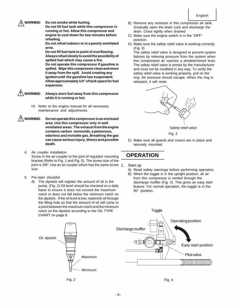
D) Make sure the safety relief valve is working correctly.(Fig. 3)The safety relief valve is designed to prevent systemfailures by relieving pressure from the system whenthis compressed air reaches a predetermined level.The safety relief valve is preset by the manufacturerand must not be modified in any way. To verify thesafety relief valve is working properly, pull on thering. Air pressure should escape. When the ring isreleased, it will reset.
E) Make sure all guards and covers are in place andsecurely mounted.
1. Start upA) Read safety warnings before performing operation.B) When the toggle is in the upright position, all air
from this compressor is vented through thedischarge muffler (Fig. 4). This gives an easy startfeature. For normal operation, the toggle is in the90° position.
English
WARNING Do not smoke while fueling.Do not fill fuel tank while this compressor isrunning or hot. Allow this compressor andengine to cool down for two minutes beforerefueling.Do not refuel indoors or in a poorly ventilatedarea.Do not fill fuel tank to point of overflowing.Always refuel slowly to avoid the possibility ofspilled fuel which may cause a fire.Do not operate this compressor if gasoline isspilled. Wipe this compressor clean and moveit away from the spill. Avoid creating anyignition until the gasolinehas evaporated.Allow approximately 1/4” of tank space for fuelexpansion.
WARNING Always store fuel away from this compressorwhile it is running or hot.
H) Refer to the engine manual for all necessarymaintenance and adjustments.
WARNING Do not operate this compressor in an enclosedarea. Use this compressor only in wellventilated areas. The exhaust from the enginecontains carbon monoxide, a poisonous,odorless and invisible gas. Breathing the gascan cause serious injury, illness and possibledeath.
4. Air coupler installationScrew in the air coupler to the joint of regulator mountingbracket (Refer to Fig. 1 and Fig. 5). The screw size of thejoint is 3/8”. Use an air coupler which has the same screwsize.
5. Pre-start checklistA) The dipstick will register the amount of oil in the
pump. (Fig. 2) Oil level should be checked on a dailybasis to ensure it does not exceed the maximumnotch or does not fall below the minimum notch onthe dipstick. If the oil level is low, replenish oil throughthe filling hole so that the amount of oil will come toa point between the maximum notch and the minimumnotch on the dipstick according to the OIL TYPECHART on page 8.
OPERATION
Fig. 2 Fig. 4
Safety relief valve
Oil dipstick
Maximum
Minimum
Fig. 3
Discharge muffler
Toggle
Pilot valve
Operating position
Easy start position
- 10 -
English
C) Start the engine. (Refer to the Engine Manualaccompanying this unit.)
D) When the engine has run for 1-2 minutes, flip toggleback to the original position.
The operation of this compressor is automatic and iscontrolled by the pilot valve which idles it when the pressurein the air-tank reaches the maximum level and restart itwhen the air pressure drops during use to the restart level.The pilot valve is preset by the manufacturer and must notbe modified in any way.
WARNING: If you notice any unusual noise or vibration, stopthis compressor.
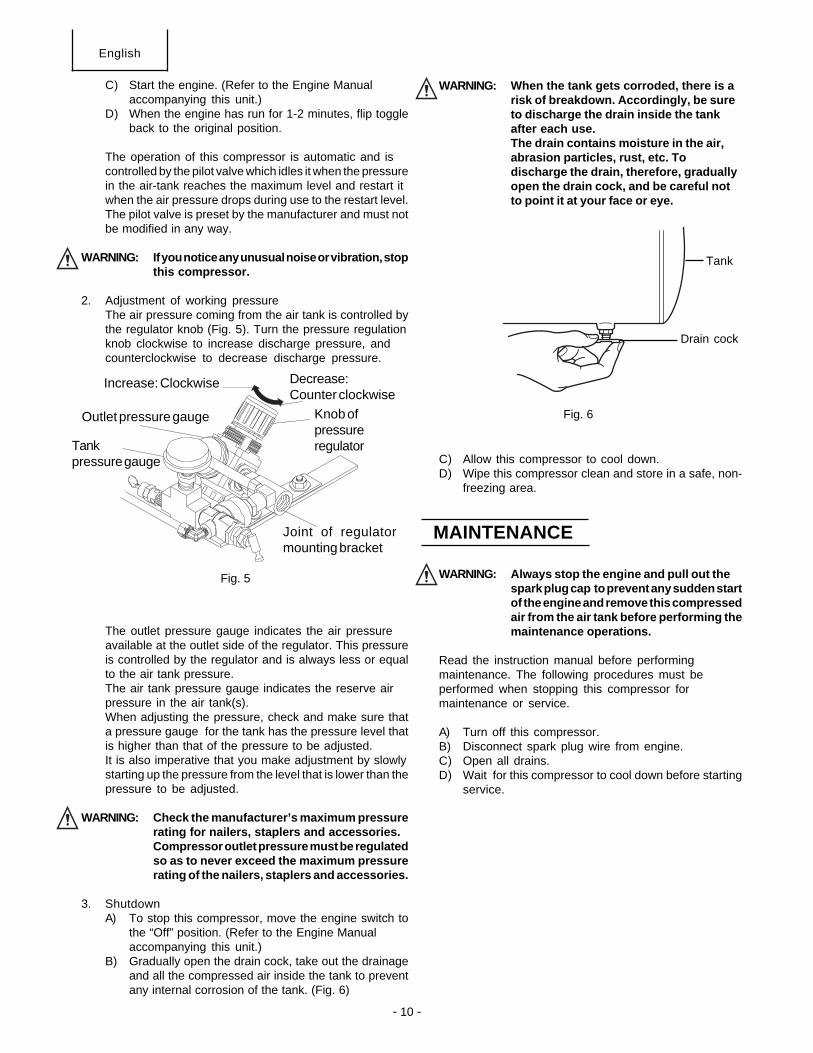
2. Adjustment of working pressureThe air pressure coming from the air tank is controlled bythe regulator knob (Fig. 5). Turn the pressure regulationknob clockwise to increase discharge pressure, andcounterclockwise to decrease discharge pressure.
The outlet pressure gauge indicates the air pressureavailable at the outlet side of the regulator. This pressureis controlled by the regulator and is always less or equalto the air tank pressure.The air tank pressure gauge indicates the reserve airpressure in the air tank(s).When adjusting the pressure, check and make sure thata pressure gauge for the tank has the pressure level thatis higher than that of the pressure to be adjusted.It is also imperative that you make adjustment by slowlystarting up the pressure from the level that is lower than thepressure to be adjusted.
WARNING: Check the manufacturer’s maximum pressurerating for nailers, staplers and accessories.Compressor outlet pressure must be regulatedso as to never exceed the maximum pressurerating of the nailers, staplers and accessories.
3. ShutdownA) To stop this compressor, move the engine switch to
the “Off” position. (Refer to the Engine Manualaccompanying this unit.)
B) Gradually open the drain cock, take out the drainageand all the compressed air inside the tank to preventany internal corrosion of the tank. (Fig. 6)
WARNING: When the tank gets corroded, there is arisk of breakdown. Accordingly, be sureto discharge the drain inside the tankafter each use.The drain contains moisture in the air,abrasion particles, rust, etc. Todischarge the drain, therefore, graduallyopen the drain cock, and be careful notto point it at your face or eye.
C) Allow this compressor to cool down.D) Wipe this compressor clean and store in a safe, non-
freezing area.
WARNING: Always stop the engine and pull out thespark plug cap to prevent any sudden startof the engine and remove this compressedair from the air tank before performing themaintenance operations.
Read the instruction manual before performingmaintenance. The following procedures must beperformed when stopping this compressor formaintenance or service.
A) Turn off this compressor.B) Disconnect spark plug wire from engine.C) Open all drains.D) Wait for this compressor to cool down before starting
service.
MAINTENANCE
Fig. 5
Fig. 6
Tank
Drain cock
Increase: Clockwise Decrease:Counter clockwise
Knob ofpressureregulator
Joint of regulatormounting bracket
Outlet pressure gauge
Tankpressure gauge
- 11 -
All quality compressors will eventually require servicing orreplacement of parts because of wear and tear from normaluse. To assure that only genuine replacement parts will beused, all service and repairs must be performed by a HITACHIAUTHORIZED SERVICE CENTER, only.
NOTE:Specifications are subject to change without any obligationon the part of the HITACHI.
English
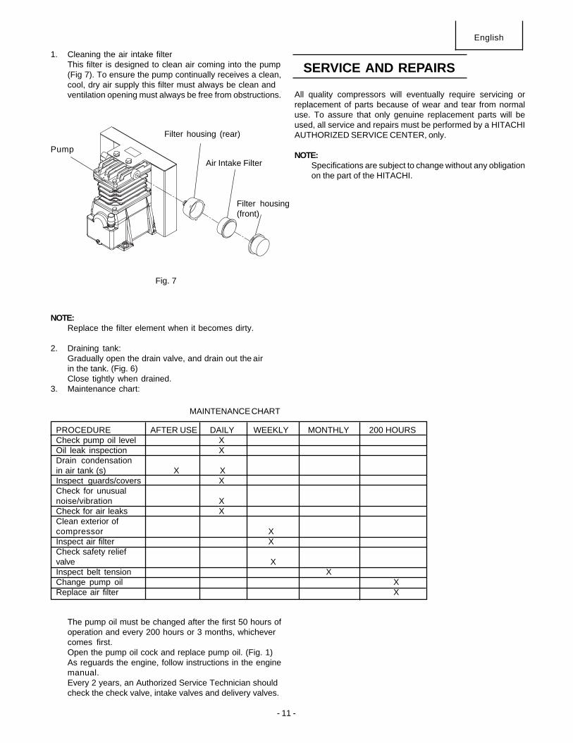
1. Cleaning the air intake filterThis filter is designed to clean air coming into the pump(Fig 7). To ensure the pump continually receives a clean,cool, dry air supply this filter must always be clean andventilation opening must always be free from obstructions.
NOTE:Replace the filter element when it becomes dirty.
2. Draining tank:Gradually open the drain valve, and drain out the airin the tank. (Fig. 6)Close tightly when drained.
3. Maintenance chart:
The pump oil must be changed after the first 50 hours ofoperation and every 200 hours or 3 months, whichevercomes first.Open the pump oil cock and replace pump oil. (Fig. 1)As reguards the engine, follow instructions in the enginemanual.Every 2 years, an Authorized Service Technician shouldcheck the check valve, intake valves and delivery valves.
SERVICE AND REPAIRS
Fig. 7
Pump
Filter housing (rear)
Air Intake Filter
Filter housing(front)
PROCEDURE AFTER USE DAILY WEEKLY MONTHLY 200 HOURSCheck pump oil level XOil leak inspection XDrain condensationin air tank (s) X XInspect guards/covers XCheck for unusualnoise/vibration XCheck for air leaks XClean exterior ofcompressor XInspect air filter XCheck safety reliefvalve XInspect belt tension XChange pump oil XReplace air filter X
MAINTENANCE CHART
- 12 -
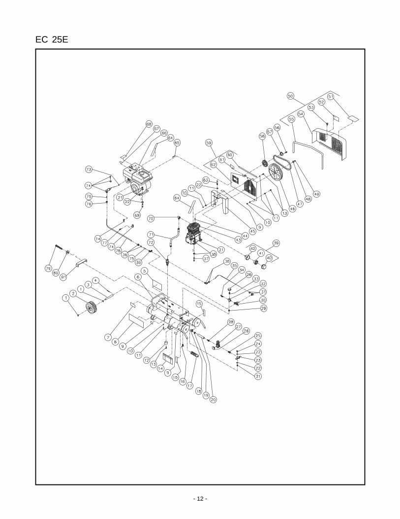
EC 25E
- 13 -
AC1-PH55-08M&H-062102-DLG
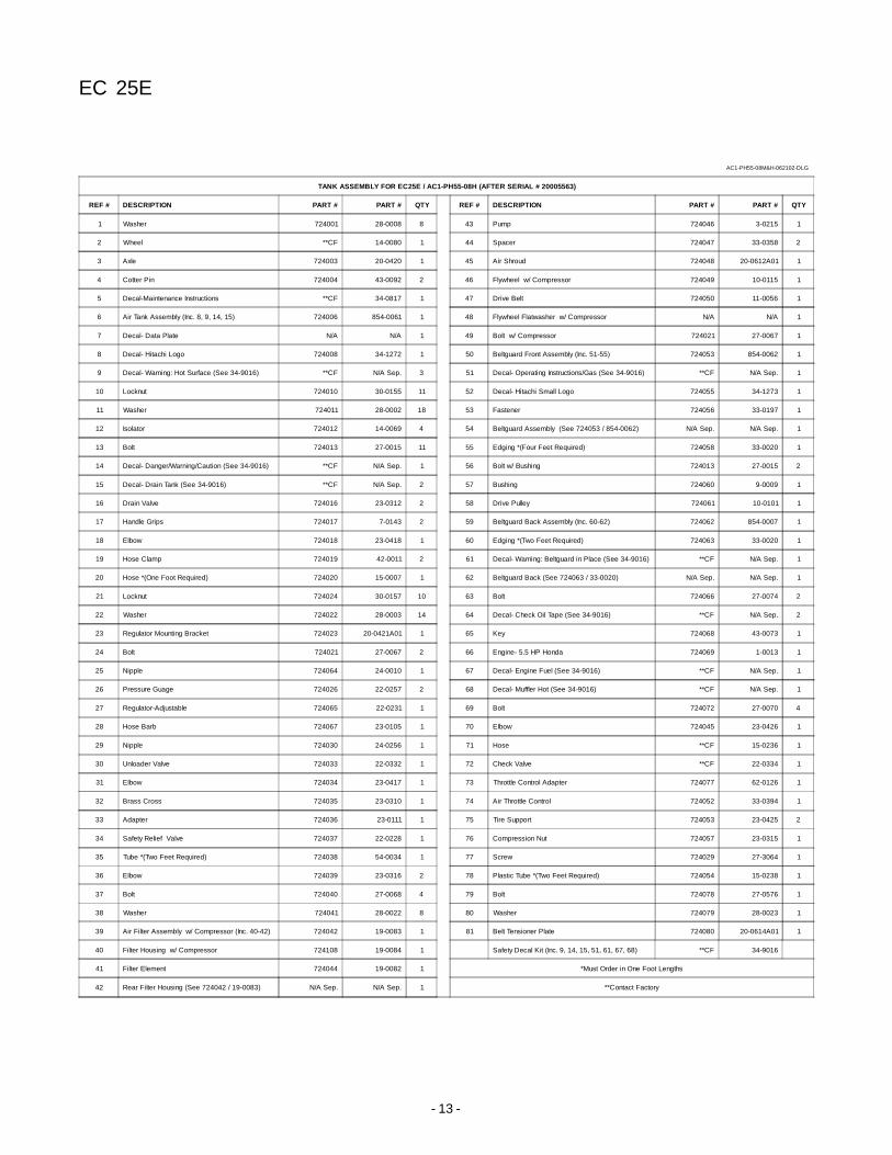
TANK ASSEMBLY FOR EC25E / AC1-PH55-08H (AFTER SERIAL # 20005563)
REF # DESCRIPTION PART # PART # QTY REF # DESCRIPTION PART # PART # QTY
1 Washer 724001 28-0008 8 43 Pump 724046 3-0215 1
2 Wheel **CF 14-0080 1 44 Spacer 724047 33-0358 2
3 Axle 724003 20-0420 1 45 Air Shroud 724048 20-0612A01 1
4 Cotter Pin 724004 43-0092 2 46 Flywheel w/ Compressor 724049 10-0115 1
5 Decal-Maintenance Instructions **CF 34-0817 1 47 Drive Belt 724050 11-0056 1
6 Air Tank Assembly (Inc. 8, 9, 14, 15) 724006 854-0061 1 48 Flywheel Flatwasher w/ Compressor N/A N/A 1
7 Decal- Data Plate N/A N/A 1 49 Bolt w/ Compressor 724021 27-0067 1
8 Decal- Hitachi Logo 724008 34-1272 1 50 Beltguard Front Assembly (Inc. 51-55) 724053 854-0062 1
9 Decal- Warning: Hot Surface (See 34-9016) **CF N/A Sep. 3 51 Decal- Operating Instructions/Gas (See 34-9016) **CF N/A Sep. 1
10 Locknut 724010 30-0155 11 52 Decal- Hitachi Small Logo 724055 34-1273 1
11 Washer 724011 28-0002 18 53 Fastener 724056 33-0197 1
12 Isolator 724012 14-0069 4 54 Beltguard Assembly (See 724053 / 854-0062) N/A Sep. N/A Sep. 1
13 Bolt 724013 27-0015 11 55 Edging *(Four Feet Required) 724058 33-0020 1
14 Decal- Danger/Warning/Caution (See 34-9016) **CF N/A Sep. 1 56 Bolt w/ Bushing 724013 27-0015 2
15 Decal- Drain Tank (See 34-9016) **CF N/A Sep. 2 57 Bushing 724060 9-0009 1
16 Drain Valve 724016 23-0312 2 58 Drive Pulley 724061 10-0101 1
17 Handle Grips 724017 7-0143 2 59 Beltguard Back Assembly (Inc. 60-62) 724062 854-0007 1
18 Elbow 724018 23-0418 1 60 Edging *(Two Feet Required) 724063 33-0020 1
19 Hose Clamp 724019 42-0011 2 61 Decal- Warning: Beltguard in Place (See 34-9016) **CF N/A Sep. 1
20 Hose *(One Foot Required) 724020 15-0007 1 62 Beltguard Back (See 724063 / 33-0020) N/A Sep. N/A Sep. 1
21 Locknut 724024 30-0157 10 63 Bolt 724066 27-0074 2
22 Washer 724022 28-0003 14 64 Decal- Check Oil Tape (See 34-9016) **CF N/A Sep. 2
23 Regulator Mounting Bracket 724023 20-0421A01 1 65 Key 724068 43-0073 1
24 Bolt 724021 27-0067 2 66 Engine- 5.5 HP Honda 724069 1-0013 1
25 Nipple 724064 24-0010 1 67 Decal- Engine Fuel (See 34-9016) **CF N/A Sep. 1
26 Pressure Guage 724026 22-0257 2 68 Decal- Muffler Hot (See 34-9016) **CF N/A Sep. 1
27 Regulator-Adjustable 724065 22-0231 1 69 Bolt 724072 27-0070 4
28 Hose Barb 724067 23-0105 1 70 Elbow 724045 23-0426 1
29 Nipple 724030 24-0256 1 71 Hose **CF 15-0236 1
30 Unloader Valve 724033 22-0332 1 72 Check Valve **CF 22-0334 1
31 Elbow 724034 23-0417 1 73 Throttle Control Adapter 724077 62-0126 1
32 Brass Cross 724035 23-0310 1 74 Air Throttle Control 724052 33-0394 1
33 Adapter 724036 23-0111 1 75 Tire Support 724053 23-0425 2
34 Safety Relief Valve 724037 22-0228 1 76 Compression Nut 724057 23-0315 1
35 Tube *(Two Feet Required) 724038 54-0034 1 77 Screw 724029 27-3064 1
36 Elbow 724039 23-0316 2 78 Plastic Tube *(Two Feet Required) 724054 15-0238 1
37 Bolt 724040 27-0068 4 79 Bolt 724078 27-0576 1
38 Washer 724041 28-0022 8 80 Washer 724079 28-0023 1
39 Air Filter Assembly w/ Compressor (Inc. 40-42) 724042 19-0083 1 81 Belt Tensioner Plate 724080 20-0614A01 1
40 Filter Housing w/ Compressor 724108 19-0084 1 Safety Decal Kit (Inc. 9, 14, 15, 51, 61, 67, 68) **CF 34-9016
41 Filter Element 724044 19-0082 1 *Must Order in One Foot Lengths
42 Rear Filter Housing (See 724042 / 19-0083) N/A Sep. N/A Sep. 1 **Contact Factory
EC 25E
- 14 -
EC 25E
- 15 -
3-0215 M & Hitachi-081301-BAR
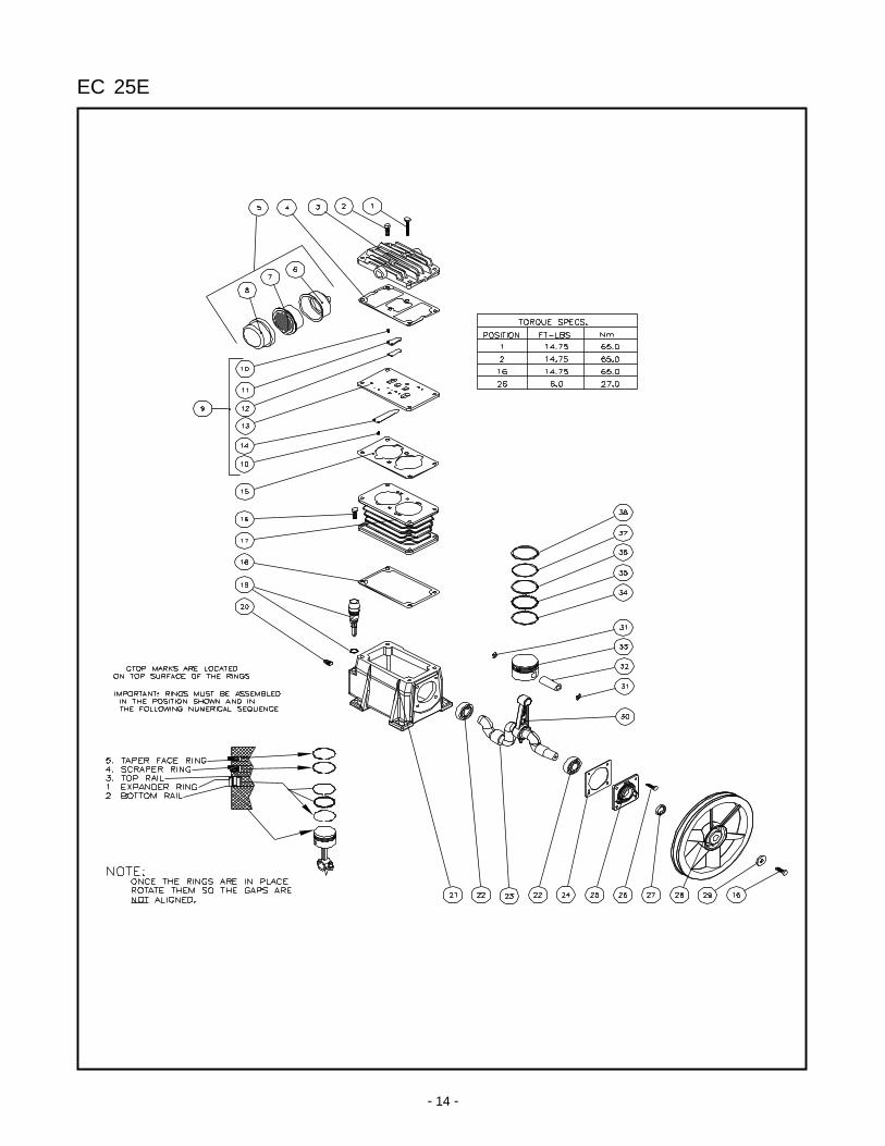
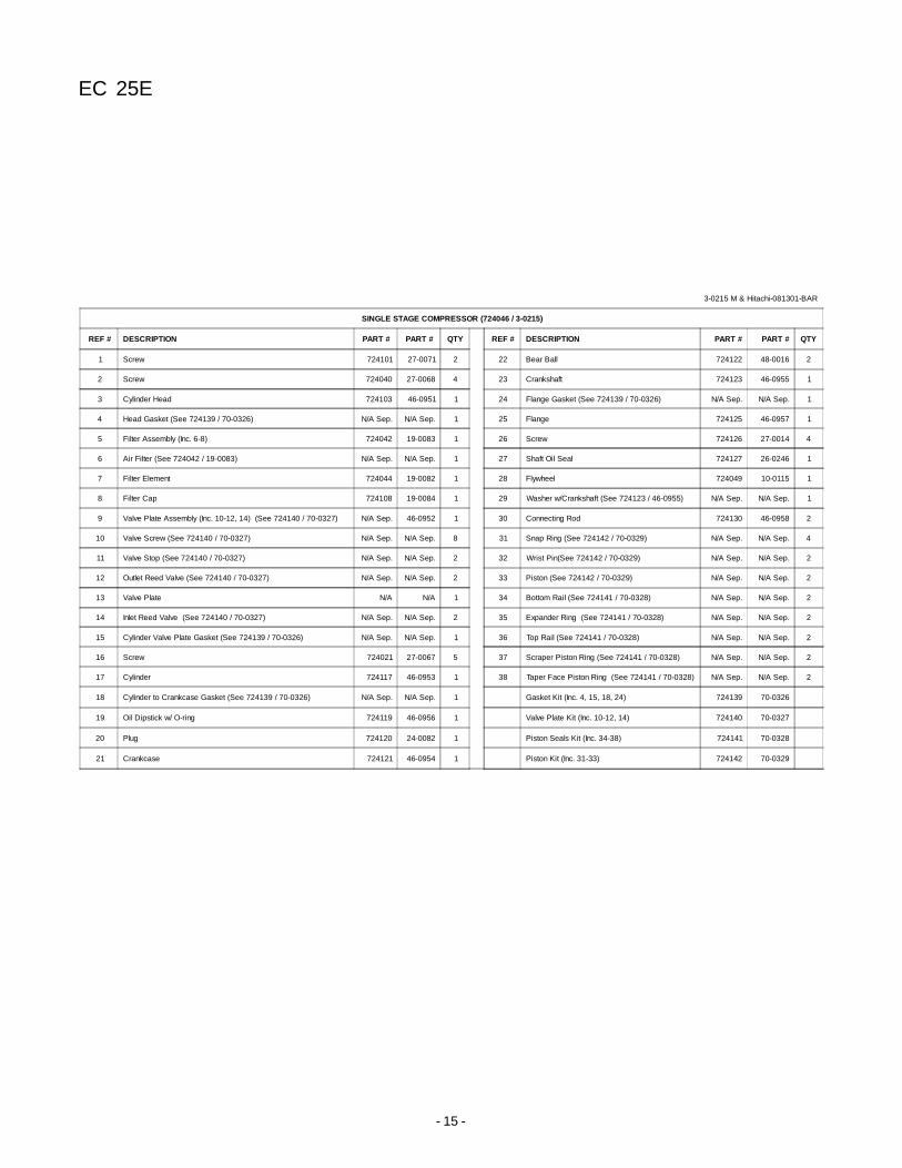
SINGLE STAGE COMPRESSOR (724046 / 3-0215)
REF # DESCRIPTION PART # PART # QTY REF # DESCRIPTION PART # PART # QTY
1 Screw 724101 27-0071 2 22 Bear Ball 724122 48-0016 2
2 Screw 724040 27-0068 4 23 Crankshaft 724123 46-0955 1
3 Cylinder Head 724103 46-0951 1 24 Flange Gasket (See 724139 / 70-0326) N/A Sep. N/A Sep. 1
4 Head Gasket (See 724139 / 70-0326) N/A Sep. N/A Sep. 1 25 Flange 724125 46-0957 1
5 Filter Assembly (Inc. 6-8) 724042 19-0083 1 26 Screw 724126 27-0014 4
6 Air Filter (See 724042 / 19-0083) N/A Sep. N/A Sep. 1 27 Shaft Oil Seal 724127 26-0246 1
7 Filter Element 724044 19-0082 1 28 Flywheel 724049 10-0115 1
8 Filter Cap 724108 19-0084 1 29 Washer w/Crankshaft (See 724123 / 46-0955) N/A Sep. N/A Sep. 1
9 Valve Plate Assembly (Inc. 10-12, 14) (See 724140 / 70-0327) N/A Sep. 46-0952 1 30 Connecting Rod 724130 46-0958 2
10 Valve Screw (See 724140 / 70-0327) N/A Sep. N/A Sep. 8 31 Snap Ring (See 724142 / 70-0329) N/A Sep. N/A Sep. 4
11 Valve Stop (See 724140 / 70-0327) N/A Sep. N/A Sep. 2 32 Wrist Pin(See 724142 / 70-0329) N/A Sep. N/A Sep. 2
12 Outlet Reed Valve (See 724140 / 70-0327) N/A Sep. N/A Sep. 2 33 Piston (See 724142 / 70-0329) N/A Sep. N/A Sep. 2
13 Valve Plate N/A N/A 1 34 Bottom Rail (See 724141 / 70-0328) N/A Sep. N/A Sep. 2
14 Inlet Reed Valve (See 724140 / 70-0327) N/A Sep. N/A Sep. 2 35 Expander Ring (See 724141 / 70-0328) N/A Sep. N/A Sep. 2
15 Cylinder Valve Plate Gasket (See 724139 / 70-0326) N/A Sep. N/A Sep. 1 36 Top Rail (See 724141 / 70-0328) N/A Sep. N/A Sep. 2
16 Screw 724021 27-0067 5 37 Scraper Piston Ring (See 724141 / 70-0328) N/A Sep. N/A Sep. 2
17 Cylinder 724117 46-0953 1 38 Taper Face Piston Ring (See 724141 / 70-0328) N/A Sep. N/A Sep. 2
18 Cylinder to Crankcase Gasket (See 724139 / 70-0326) N/A Sep. N/A Sep. 1 Gasket Kit (Inc. 4, 15, 18, 24) 724139 70-0326
19 Oil Dipstick w/ O-ring 724119 46-0956 1 Valve Plate Kit (Inc. 10-12, 14) 724140 70-0327
20 Plug 724120 24-0082 1 Piston Seals Kit (Inc. 34-38) 724141 70-0328
21 Crankcase 724121 46-0954 1 Piston Kit (Inc. 31-33) 724142 70-0329
EC 25E
- 16 -
Issued by
Hitachi Koki Co., Ltd.Sinagawa Intercity Tower A, 15-1, Konan 2-chome,
Minato-Ku, Tokyo 108-6020, Japan
Distributed by
Hitachi Koki U.S.A., Ltd.3950 Steve Reynolds Blvd.
Norcross, GA 30093
Hitachi Koki Canada Co.6395 Kestrel Road
Mississauga ON L5T 1Z5
108Code No. C99109061Printed in U.S.A.