model 7520 dsu user's guide - dasan zhonesupport.dasanzhone.com/support/manuals/docs/75/... ·...
TRANSCRIPT

MODEL 7520 DSUUSER’S GUIDE
Document No. 7520-A2-GB20-20
May 1998
Printed on recycled paper
A 7520-A2-GB20-20May 1998
Copyright � 1998 Paradyne Corporation.All rights reserved.Printed in U.S.A.
Notice
This publication is protected by federal copyright law. No part of this publication may be copied or distributed,transmitted, transcribed, stored in a retrieval system, or translated into any human or computer language in any formor by any means, electronic, mechanical, magnetic, manual or otherwise, or disclosed to third parties without theexpress written permission of Paradyne Corporation, 8545 126th Avenue North, P.O. Box 2826, Largo,Florida 33779-2826.
Paradyne Corporation makes no representation or warranties with respect to the contents hereof and specificallydisclaims any implied warranties of merchantability or fitness for a particular purpose. Further, Paradyne Corporationreserves the right to revise this publication and to make changes from time to time in the contents hereof withoutobligation of Paradyne Corporation to notify any person of such revision or changes.
Changes and enhancements to the product and to the information herein will be documented and issued as a newrelease to this manual.
Trademarks
All products and services mentioned herein are the trademarks, service marks, registered trademarks or registeredservice marks of their respective owners.
Warranty, Sales, and Service Information
Contact your local sales representative, service representative, or distributor directly for any help needed. Foradditional information concerning warranty, sales, service, repair, installation, documentation, training, distributorlocations, or Paradyne worldwide office locations, use one of the following methods:
� Via the Internet: Visit the Paradyne World Wide Web site at http://www.paradyne.com
� Via Telephone: Call our automated call system to receive current information via fax or to speak with a company representative.
— Within the U.S.A., call 1-800-870-2221— Outside the U.S.A., call 1-727-530-2340
i7520-A2-GB20-20 May 1998
Contents
About This Guide� Document Purpose and Intended Audience v. . . . . . . . . . . . . . . . . . . . . . . . .
� Document Summary v. . . . . . . . . . . . . . . . . . . . . . . . . . . . . . . . . . . . . . . . . . . . .
� Product-Related Documents vi. . . . . . . . . . . . . . . . . . . . . . . . . . . . . . . . . . . . . .
1 About the DSU� Model 7520 DSU Features 1-1. . . . . . . . . . . . . . . . . . . . . . . . . . . . . . . . . . . . . . .
� Typical DSU Configurations 1-2. . . . . . . . . . . . . . . . . . . . . . . . . . . . . . . . . . . . . .
� User Interfaces 1-3. . . . . . . . . . . . . . . . . . . . . . . . . . . . . . . . . . . . . . . . . . . . . . . . .
� Rear Panel Interfaces 1-4. . . . . . . . . . . . . . . . . . . . . . . . . . . . . . . . . . . . . . . . . . .
2 Using the Asynchronous Terminal Interface� Connecting to the Terminal Port 2-1. . . . . . . . . . . . . . . . . . . . . . . . . . . . . . . . . . .
� Initiating an ATI Session 2-2. . . . . . . . . . . . . . . . . . . . . . . . . . . . . . . . . . . . . . . . .
� Screen Format Types 2-3. . . . . . . . . . . . . . . . . . . . . . . . . . . . . . . . . . . . . . . . . . . .
What Affects Screen Displays 2-3. . . . . . . . . . . . . . . . . . . . . . . . . . . . . . . . .
Screen Work Areas 2-4. . . . . . . . . . . . . . . . . . . . . . . . . . . . . . . . . . . . . . . . . .
� Navigating the Screens 2-5. . . . . . . . . . . . . . . . . . . . . . . . . . . . . . . . . . . . . . . . . .
Keyboard Keys 2-5. . . . . . . . . . . . . . . . . . . . . . . . . . . . . . . . . . . . . . . . . . . . . .
Screen Function Keys 2-6. . . . . . . . . . . . . . . . . . . . . . . . . . . . . . . . . . . . . . . .
Switching to the Screen Function Key Area 2-7. . . . . . . . . . . . . . . . . . . . .
� Ending an ATI Session 2-8. . . . . . . . . . . . . . . . . . . . . . . . . . . . . . . . . . . . . . . . . . .
Contents
ii 7520-A2-GB20-20May 1998
3 Customizing the DSU� Identifying the Device and System 3-1. . . . . . . . . . . . . . . . . . . . . . . . . . . . . . . . .
Saving Configuration Options 3-2. . . . . . . . . . . . . . . . . . . . . . . . . . . . . . . . .
� Configuring the DSU 3-3. . . . . . . . . . . . . . . . . . . . . . . . . . . . . . . . . . . . . . . . . . . .
Configuration Option Areas 3-3. . . . . . . . . . . . . . . . . . . . . . . . . . . . . . . . . . .
Accessing and Displaying Configuration Options 3-3. . . . . . . . . . . . . . . .
4 Monitoring the DSU� What to Monitor 4-1. . . . . . . . . . . . . . . . . . . . . . . . . . . . . . . . . . . . . . . . . . . . . . . . .
� Viewing System and Test Status 4-2. . . . . . . . . . . . . . . . . . . . . . . . . . . . . . . . . .
Health and Status 4-3. . . . . . . . . . . . . . . . . . . . . . . . . . . . . . . . . . . . . . . . . . .
Self-Test Results 4-4. . . . . . . . . . . . . . . . . . . . . . . . . . . . . . . . . . . . . . . . . . . .
Test Status Messages 4-5. . . . . . . . . . . . . . . . . . . . . . . . . . . . . . . . . . . . . . . .
� Viewing Network Interface Status 4-6. . . . . . . . . . . . . . . . . . . . . . . . . . . . . . . . .
� Viewing Network Performance Statistics 4-7. . . . . . . . . . . . . . . . . . . . . . . . . . .
� Monitoring the LEDs 4-8. . . . . . . . . . . . . . . . . . . . . . . . . . . . . . . . . . . . . . . . . . . . .
System LEDs 4-9. . . . . . . . . . . . . . . . . . . . . . . . . . . . . . . . . . . . . . . . . . . . . . .
Network LEDs 4-10. . . . . . . . . . . . . . . . . . . . . . . . . . . . . . . . . . . . . . . . . . . . . .
Port LEDs 4-11. . . . . . . . . . . . . . . . . . . . . . . . . . . . . . . . . . . . . . . . . . . . . . . . . .
5 Testing� Accessing the Test Menu 5-1. . . . . . . . . . . . . . . . . . . . . . . . . . . . . . . . . . . . . . . . .
� Running Network Tests 5-3. . . . . . . . . . . . . . . . . . . . . . . . . . . . . . . . . . . . . . . . . .
CSU or External Network Loopback 5-4. . . . . . . . . . . . . . . . . . . . . . . . . . . .
DSU or Internal Network Loopback 5-5. . . . . . . . . . . . . . . . . . . . . . . . . . . .
Send V.54 Up/Down Sequences 5-5. . . . . . . . . . . . . . . . . . . . . . . . . . . . . . .
511 Test Pattern for the Network 5-6. . . . . . . . . . . . . . . . . . . . . . . . . . . . . . .
� Running Data Port Tests 5-7. . . . . . . . . . . . . . . . . . . . . . . . . . . . . . . . . . . . . . . . .
Local Loopback 5-8. . . . . . . . . . . . . . . . . . . . . . . . . . . . . . . . . . . . . . . . . . . . .
511 Test Pattern for the DTE 5-8. . . . . . . . . . . . . . . . . . . . . . . . . . . . . . . . . .
� Running the Lamp Test 5-9. . . . . . . . . . . . . . . . . . . . . . . . . . . . . . . . . . . . . . . . . .
� Ending an Active Test 5-10. . . . . . . . . . . . . . . . . . . . . . . . . . . . . . . . . . . . . . . . . . . .
Contents
iii7520-A2-GB20-20 May 1998
6 Messages and Troubleshooting� Messages and Troubleshooting 6-1. . . . . . . . . . . . . . . . . . . . . . . . . . . . . . . . . . .
� Responding to Device Messages 6-1. . . . . . . . . . . . . . . . . . . . . . . . . . . . . . . . . .
� Troubleshooting 6-3. . . . . . . . . . . . . . . . . . . . . . . . . . . . . . . . . . . . . . . . . . . . . . . . .
� Resetting the DSU 6-4. . . . . . . . . . . . . . . . . . . . . . . . . . . . . . . . . . . . . . . . . . . . . .
� Displaying DSU Identity Information 6-4. . . . . . . . . . . . . . . . . . . . . . . . . . . . . . .
A Configuration Option Tables� Overview A-1. . . . . . . . . . . . . . . . . . . . . . . . . . . . . . . . . . . . . . . . . . . . . . . . . . . . . .
� System Options Menu A-2. . . . . . . . . . . . . . . . . . . . . . . . . . . . . . . . . . . . . . . . . . .
� Network Interface Options Menu A-4. . . . . . . . . . . . . . . . . . . . . . . . . . . . . . . . . .
� Data Port Options Menu A-5. . . . . . . . . . . . . . . . . . . . . . . . . . . . . . . . . . . . . . . . .
� Terminal Port Options A-8. . . . . . . . . . . . . . . . . . . . . . . . . . . . . . . . . . . . . . . . . . . .
B Worksheets� Overview B-1. . . . . . . . . . . . . . . . . . . . . . . . . . . . . . . . . . . . . . . . . . . . . . . . . . . . . .
� Configuration Worksheets B-1. . . . . . . . . . . . . . . . . . . . . . . . . . . . . . . . . . . . . . . .
C Cables and Pin Assignments� Overview C-1. . . . . . . . . . . . . . . . . . . . . . . . . . . . . . . . . . . . . . . . . . . . . . . . . . . . . .
� Terminal Port EIA-232 Connector C-2. . . . . . . . . . . . . . . . . . . . . . . . . . . . . . . . .
� EIA-232 User Data Port Connector C-3. . . . . . . . . . . . . . . . . . . . . . . . . . . . . . . .
� V.35 User Data Port Connector C-4. . . . . . . . . . . . . . . . . . . . . . . . . . . . . . . . . . .
� Standard EIA-232D Crossover Cable C-5. . . . . . . . . . . . . . . . . . . . . . . . . . . . . .
� Modular RJ48S DDS Network Interface Cable C-6. . . . . . . . . . . . . . . . . . . . . .
D Technical Specifications
Glossary
Index

Contents
iv 7520-A2-GB20-20May 1998
This page intentionally left blank.
v7520-A2-GB20-20 May 1998
About This Guide
Document Purpose and Intended Audience
This guide contains information needed to set up, configure, and operate theModel 7520 DSU and is intended for installers and operators.
Document Summary
Section Description
Chapter 1 About the DSU. Describes the DSU features and showsexamples of typical configurations.
Chapter 2 Using the Asynchronous Terminal Interface. Providesinstructions for accessing the user interface and navigatingthe screens.
Chapter 3 Customizing the DSU. Provides procedures for setting upthe user interface and DSU configuration.
Chapter 4 Monitoring the DSU. Describes monitoring the DSU usingthe LEDs, DSU status, and network statistics.
Chapter 5 Testing. Provides details about available tests and testsetup.
Chapter 6 Messages and Troubleshooting. Provides information ondevice messages and troubleshooting, and procedures forresetting the unit and viewing unit identification information.
Appendix A Configuration Option Tables. Contains all configurationoptions, default settings, and possible settings.
Appendix B Worksheets. Contains all the configuration options, defaultsettings, and possible settings to use for planning.
Appendix C Cables and Pin Assignments. Contains connector andinterface information.
Appendix D Technical Specifications. Contains physical and regulatoryspecifications of the DSU.
About This Guide
vi 7520-A2-GB20-20May 1998
Section Description
Glossary Defines acronyms and terms used in this document.
Index Lists key terms, acronyms, concepts, and sections inalphabetical order.
Product-Related Documents
Document Number Document Title
7520-A2-GN10 Model 7520 DSU Startup Instructions
Contact your sales or service representative to order additional productdocumentation.
Paradyne documents are also available on the World Wide Web at:
http://www.paradyne.com
Select Service & Support → Technical Manuals
1-17520-A2-GB20-20 May 1998
About the DSU
1Model 7520 DSU Features
The Model 7520 DSU provides an interface between the customer premisesequipment (CPE) and a Digital Data Service (DDS) network.
The DSU’s features and capabilities include:
� Easy Installation. Connects to your equipment using standard connectorsand cables.
� Easy Configuration. A compact and well-designed set of configurationoptions minimizes your customization effort.
� DDS Operation. Operates at 2.4, 4.8, 9.6, 19.2, 38.4, 56, and 64 kbps CC(clear channel).
� Local Area Data Set (LADS) Operation. Operates at 2.4, 4.8, 9.6, 19.2,38.4, 56, and 64 kbps full-duplex as a limited-distance modem.
� Asynchronous Terminal Interface (ATI). Provides a menu-drivenVT100-compatible interface for configuring and managing the DSU.
— Local Management. Provides local management using an asynchronousterminal connection through the Terminal port.
— Remote Management. Provides remote management using an externalmodem through the Terminal port.
� Diagnostics. Lets you diagnose device and network problems with digitalloopbacks and pattern tests.
� Device and Test Monitoring. Lets you track and evaluate the unit’soperation with status and test result information.
� High Reliability. The Model 7520 DSU’s MTBF (Mean Time BetweenFailures) is calculated at over 30 years.
About the DSU
1-2 7520-A2-GB20-20May 1998
Typical DSU Configurations
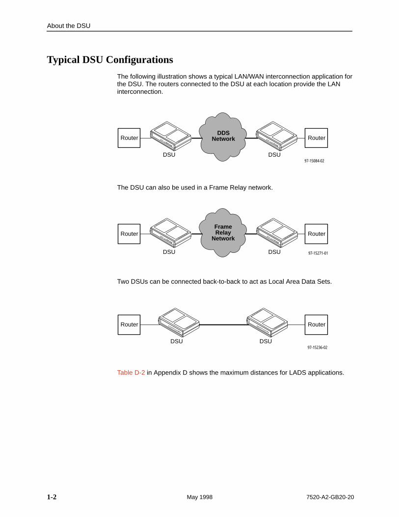
The following illustration shows a typical LAN/WAN interconnection application forthe DSU. The routers connected to the DSU at each location provide the LANinterconnection.
DDSNetwork
97-15084-02DSU DSU
RouterRouter
The DSU can also be used in a Frame Relay network.
FrameRelay
Network
97-15271-01DSU DSU
RouterRouter
Two DSUs can be connected back-to-back to act as Local Area Data Sets.
97-15236-02DSU DSU
RouterRouter
Table D-2 in Appendix D shows the maximum distances for LADS applications.
About the DSU
1-37520-A2-GB20-20 May 1998
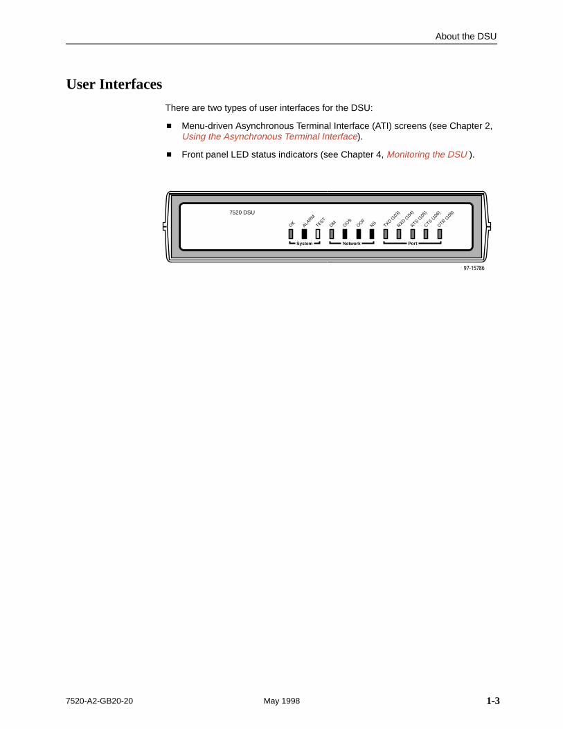
User Interfaces
There are two types of user interfaces for the DSU:
� Menu-driven Asynchronous Terminal Interface (ATI) screens (see Chapter 2,Using the Asynchronous Terminal Interface).
� Front panel LED status indicators (see Chapter 4, Monitoring the DSU ).
97-15786
NetworkSystem Port
CTS (106
)
OK ALARM
TESTDM OOS
OOFNS TXD (1
03)
RXD (104
)
RTS (105
)
DTR (108
)7520 DSU
About the DSU
1-4 7520-A2-GB20-20May 1998
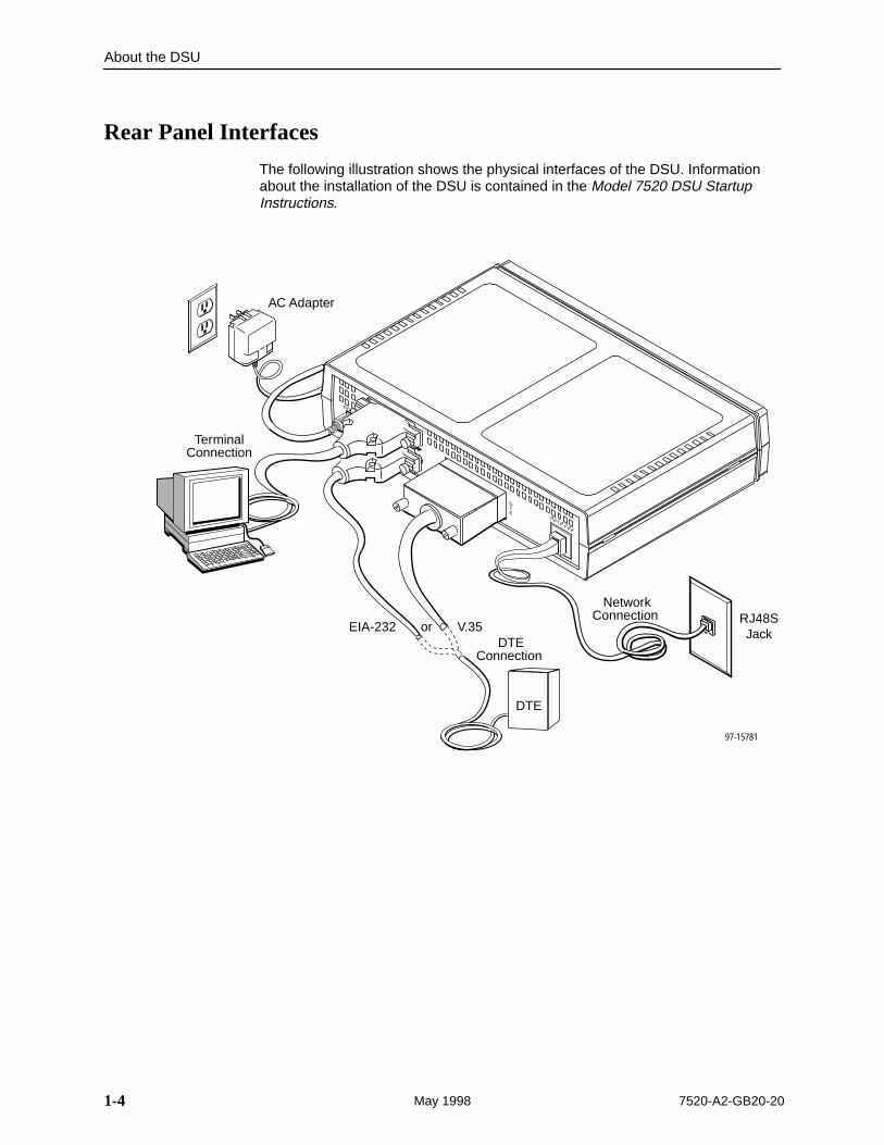
Rear Panel Interfaces
The following illustration shows the physical interfaces of the DSU. Informationabout the installation of the DSU is contained in the Model 7520 DSU StartupInstructions.
97-15781
RJ48SJack
NETWORK
TERMINAL MANAGEMENT
POWER
DTE
DTE
EIA-232
TerminalConnection
AC Adapter
NetworkConnection
DTEConnection
or V.35
2-17520-A2-GB20-20 May 1998
Using the AsynchronousTerminal Interface
2Connecting to the Terminal Port
The device used for the Asynchronous Terminal Interface (ATI) can be aVT100-compatible async terminal, or a PC running emulation software. Theterminal or PC can be connected to the Terminal port directly, or through anexternal modem.
Ensure that the device you connect communicates using these settings:
� Data rate set to 9.6 kbps.
� Character length set to 8.
� Parity set to None.
� Stop Bits set to 1.
Terminal port settings cannot be changed using the ATI.
Using the Asynchronous Terminal Interface
2-2 7520-A2-GB20-20May 1998
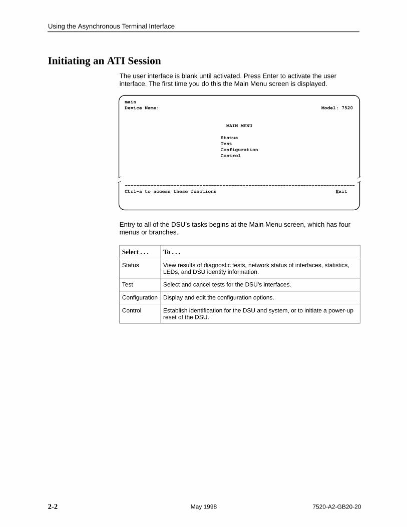
Initiating an ATI SessionThe user interface is blank until activated. Press Enter to activate the userinterface. The first time you do this the Main Menu screen is displayed.
mainDevice Name: Model: 7520
MAIN MENU
StatusTestConfigurationControl
––––––––––––––––––––––––––––––––––––––––––––––––––––––––––––––––––––––––––––––––Ctrl-a to access these functions E xit
Î ÎÎ
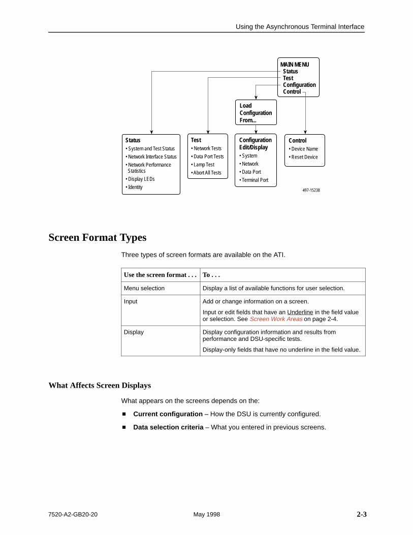
Entry to all of the DSU’s tasks begins at the Main Menu screen, which has fourmenus or branches.
Select . . . To . . .
Status View results of diagnostic tests, network status of interfaces, statistics,LEDs, and DSU identity information.
Test Select and cancel tests for the DSU’s interfaces.
Configuration Display and edit the configuration options.
Control Establish identification for the DSU and system, or to initiate a power-upreset of the DSU.
Using the Asynchronous Terminal Interface
2-37520-A2-GB20-20 May 1998
ConfigurationEdit/Display• System
• Network
• Data Port
• Terminal Port
Status• System and Test Status
• Network Interface Status
• Network Performance Statistics
• Display LEDs
• Identity
Test• Network Tests
• Data Port Tests
• Lamp Test
• Abort All Tests
Control• Device Name
• Reset Device
MAIN MENU Status Test Configuration Control
497-15238
LoadConfigurationFrom...
Screen Format Types
Three types of screen formats are available on the ATI.
Use the screen format . . . To . . .
Menu selection Display a list of available functions for user selection.
Input Add or change information on a screen.
Input or edit fields that have an Underline in the field valueor selection. See Screen Work Areas on page 2-4.
Display Display configuration information and results fromperformance and DSU-specific tests.
Display-only fields that have no underline in the field value.
What Affects Screen Displays
What appears on the screens depends on the:
� Current configuration – How the DSU is currently configured.
� Data selection criteria – What you entered in previous screens.
Using the Asynchronous Terminal Interface
2-4 7520-A2-GB20-20May 1998
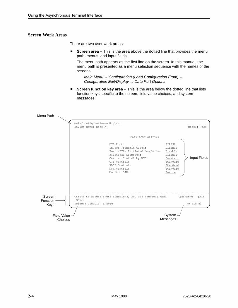
Screen Work Areas
There are two user work areas:
� Screen area – This is the area above the dotted line that provides the menupath, menus, and input fields.
The menu path appears as the first line on the screen. In this manual, themenu path is presented as a menu selection sequence with the names of thescreens:
Main Menu →Configuration (Load Configuration From) → Configuration Edit/Display → Data Port Options
� Screen function key area – This is the area below the dotted line that listsfunction keys specific to the screen, field value choices, and systemmessages.
ÎÎÎÎÎÎÎÎÎÎÎÎÎÎÎÎÎÎÎÎÎÎÎÎÎÎÎÎÎÎÎÎÎÎÎÎÎÎÎÎÎÎÎÎÎÎÎÎÎÎÎÎÎÎÎÎÎÎÎÎÎÎÎÎÎÎÎÎÎÎÎÎÎÎÎÎÎÎÎÎÎÎÎÎÎÎÎÎÎÎÎÎÎÎÎÎÎÎÎÎÎÎÎÎÎÎÎÎÎÎÎÎÎÎÎÎÎÎÎÎÎÎÎÎÎÎÎÎÎÎÎÎÎÎÎÎÎÎÎÎÎÎÎÎÎÎÎÎÎÎÎÎÎÎÎÎÎÎÎÎÎÎÎÎÎÎÎÎÎÎÎÎÎÎÎÎÎÎÎÎÎÎÎÎÎÎÎÎÎÎÎÎÎÎÎÎÎÎÎÎÎÎÎÎÎÎÎÎÎÎÎÎÎÎÎÎÎÎÎÎÎÎÎÎÎÎÎÎÎÎÎÎÎÎÎÎÎÎÎÎÎÎÎÎÎÎÎÎÎÎÎÎÎÎÎÎÎÎÎÎÎÎÎÎÎÎÎÎÎÎÎÎÎÎÎÎÎÎÎÎÎÎÎÎÎÎÎÎÎÎÎÎÎÎÎÎÎÎÎÎÎÎÎÎÎÎÎÎÎÎÎÎÎÎÎÎÎÎÎÎÎÎÎÎÎÎÎÎÎÎÎÎÎÎÎÎÎÎÎÎÎÎÎÎÎÎÎÎÎÎÎÎÎÎÎÎÎÎÎÎÎÎÎÎÎÎÎÎÎÎÎÎÎÎÎÎÎÎÎÎÎÎÎÎÎÎÎÎÎÎÎÎÎÎÎÎÎÎÎÎ
Menu Path
ScreenFunction
Keys
Field ValueChoices
SystemMessages
Input Fields
main/configuration/edit/portDevice Name: Node A Model: 7520
DATA PORT OPTIONS
DTE Port: EIA232 Invert Transmit Clock: DisablePort (DTE) Initiated Loopbacks: DisableBilateral Loopback: DisableCarrier Control by RTS: ConstantCTS Control: StandardRLSD Control: StandardDSR Control: StandardMonitor DTR: Enable
––––––––––––––––––––––––––––––––––––––––––––––––––––––––––––––––––––––––––––––––Ctrl-a to access these functions, ESC for previous menu M ainMenu E xit S aveSelect: Disable, Enable No Signal
Using the Asynchronous Terminal Interface
2-57520-A2-GB20-20 May 1998
Navigating the Screens
You can navigate the screens by:
� Using keyboard keys
� Using screen function keys
� Switching between the two screen work areas
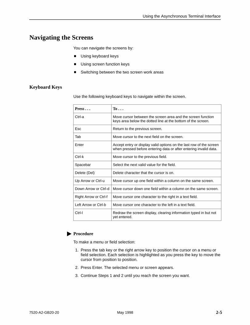
Keyboard Keys
Use the following keyboard keys to navigate within the screen.
Press . . . To . . .
Ctrl-a Move cursor between the screen area and the screen functionkeys area below the dotted line at the bottom of the screen.
Esc Return to the previous screen.
Tab Move cursor to the next field on the screen.
Enter Accept entry or display valid options on the last row of the screenwhen pressed before entering data or after entering invalid data.
Ctrl-k Move cursor to the previous field.
Spacebar Select the next valid value for the field.
Delete (Del) Delete character that the cursor is on.
Up Arrow or Ctrl-u Move cursor up one field within a column on the same screen.
Down Arrow or Ctrl-d Move cursor down one field within a column on the same screen.
Right Arrow or Ctrl-f Move cursor one character to the right in a text field.
Left Arrow or Ctrl-b Move cursor one character to the left in a text field.
Ctrl-l Redraw the screen display, clearing information typed in but notyet entered.
� Procedure
To make a menu or field selection:
1. Press the tab key or the right arrow key to position the cursor on a menu orfield selection. Each selection is highlighted as you press the key to move thecursor from position to position.
2. Press Enter. The selected menu or screen appears.
3. Continue Steps 1 and 2 until you reach the screen you want.
Using the Asynchronous Terminal Interface
2-6 7520-A2-GB20-20May 1998
The current setting or value appears to the right of the field name. The validchoices for the field are displayed in the screen function area. You can enterinformation into a selected field by typing in the first letter or letters of a field valueor command.
If a field is blank and the Field Values screen area displays valid selections, pressthe space bar and the first valid value for the field will appear. Continue pressingthe space bar to scroll through other valid values.
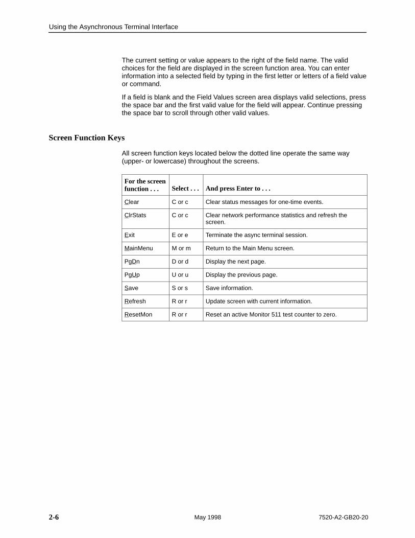
Screen Function Keys
All screen function keys located below the dotted line operate the same way(upper- or lowercase) throughout the screens.
For the screenfunction . . . Select . . . And press Enter to . . .
Clear C or c Clear status messages for one-time events.
ClrStats C or c Clear network performance statistics and refresh thescreen.
Exit E or e Terminate the async terminal session.
MainMenu M or m Return to the Main Menu screen.
PgDn D or d Display the next page.
PgUp U or u Display the previous page.
Save S or s Save information.
Refresh R or r Update screen with current information.
ResetMon R or r Reset an active Monitor 511 test counter to zero.
Using the Asynchronous Terminal Interface
2-77520-A2-GB20-20 May 1998
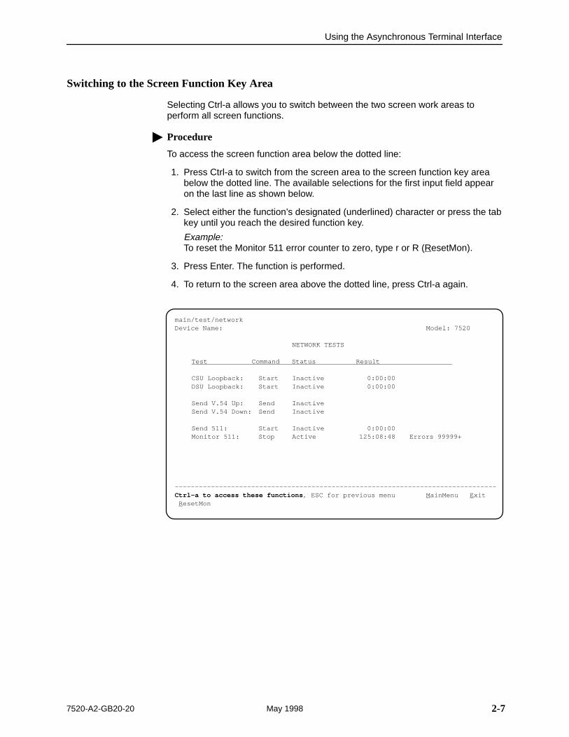
Switching to the Screen Function Key Area
Selecting Ctrl-a allows you to switch between the two screen work areas toperform all screen functions.
� Procedure
To access the screen function area below the dotted line:
1. Press Ctrl-a to switch from the screen area to the screen function key areabelow the dotted line. The available selections for the first input field appearon the last line as shown below.
2. Select either the function’s designated (underlined) character or press the tabkey until you reach the desired function key.
Example:To reset the Monitor 511 error counter to zero, type r or R (ResetMon).
3. Press Enter. The function is performed.
4. To return to the screen area above the dotted line, press Ctrl-a again.
ÎÎÎÎÎÎÎÎÎÎÎÎÎÎÎÎÎÎÎÎÎÎÎÎÎÎÎÎÎÎÎÎÎÎÎÎÎÎÎÎÎÎÎÎÎÎÎÎÎÎÎÎÎÎÎÎÎÎÎÎÎÎÎÎÎÎÎÎÎÎÎÎÎÎÎÎÎÎÎÎÎÎÎÎÎÎÎÎÎÎÎÎÎÎÎÎÎÎÎÎÎÎÎÎÎÎÎÎÎÎÎÎÎÎÎÎÎÎÎÎÎÎÎÎÎÎÎÎÎÎÎÎÎÎÎÎÎÎÎÎÎÎÎÎÎÎÎÎÎÎÎÎÎÎÎÎÎÎÎÎÎÎÎÎÎÎÎÎÎÎÎÎÎÎÎÎÎÎÎÎÎÎÎÎÎÎÎÎÎÎÎÎÎÎÎÎÎÎÎÎÎÎÎÎÎÎÎÎÎÎÎÎÎÎÎÎÎÎÎÎÎÎÎÎÎÎÎÎÎÎÎÎÎÎÎÎÎÎÎÎÎÎÎÎÎÎÎÎÎÎÎÎÎÎÎÎÎÎÎÎÎÎÎÎÎÎÎÎÎÎÎÎÎÎÎÎÎÎÎÎÎÎÎÎÎÎÎÎÎÎÎÎÎÎÎÎÎÎÎÎÎÎÎÎÎÎÎÎÎÎÎÎÎÎÎÎÎÎÎÎÎÎÎÎÎÎÎÎÎÎÎÎÎÎÎÎÎÎÎÎÎÎÎÎÎÎÎÎÎÎÎÎÎÎÎÎÎÎÎÎÎÎÎÎÎÎÎÎÎÎÎÎÎÎÎÎÎÎÎÎÎÎÎÎÎÎÎÎÎÎÎÎÎÎÎÎÎÎÎÎ
main/test/networkDevice Name: Model: 7520
NETWORK TESTS
Test Command Status Result
CSU Loopback: Start Inactive 0:00:00DSU Loopback: Start Inactive 0:00:00
Send V.54 Up: Send InactiveSend V.54 Down: Send Inactive
Send 511: Start Inactive 0:00:00Monitor 511: Stop Active 125:08:48 Errors 99999+
––––––––––––––––––––––––––––––––––––––––––––––––––––––––––––––––––––––––––––––––Ctrl-a to access these functions , ESC for previous menu M ainMenu E xit R esetMon
Using the Asynchronous Terminal Interface
2-8 7520-A2-GB20-20May 1998
Ending an ATI Session
Use the Exit function key from any screen to terminate the session.
� Procedure
To end an ATI session:
1. Press Ctrl-a to go to the screen function key area below the dotted line.
2. Save changes if required. A confirmation message appears if you have madebut not saved changes to your configuration.
3. Tab to Exit (or type e or E) and press Enter. The User Interface Idle screenappears.
3-17520-A2-GB20-20 May 1998
Customizing the DSU
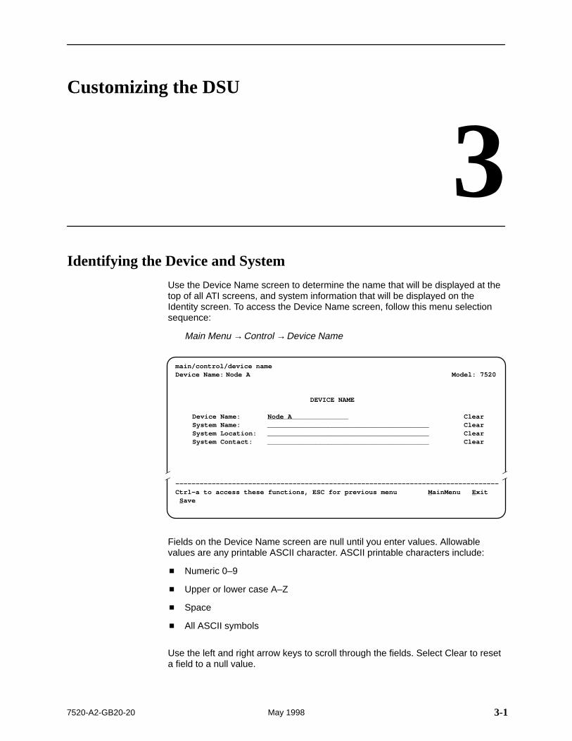
3Identifying the Device and System
Use the Device Name screen to determine the name that will be displayed at thetop of all ATI screens, and system information that will be displayed on theIdentity screen. To access the Device Name screen, follow this menu selectionsequence:
Main Menu →Control →Device Name
main/control/device nameDevice Name: Node A Model: 7520
DEVICE NAME
Device Name: Node A ClearSystem Name: ________________________________________ ClearSystem Location: ________________________________________ ClearSystem Contact: ________________________________________ Clear
––––––––––––––––––––––––––––––––––––––––––––––––––––––––––––––––––––––––––––––––Ctrl-a to access these functions, ESC for previous menu M ainMenu E xit S ave
ÎÎ
ÎÎÎÎ
Fields on the Device Name screen are null until you enter values. Allowablevalues are any printable ASCII character. ASCII printable characters include:
� Numeric 0–9
� Upper or lower case A–Z
� Space
� All ASCII symbols
Use the left and right arrow keys to scroll through the fields. Select Clear to reseta field to a null value.
Customizing the DSU
3-2 7520-A2-GB20-20May 1998
� Procedure
To enter Device Name screen information:
1. Position the cursor in the Device Name field. Enter a name unique in yoursystem to identify the unit.
The maximum length of Device Name is 20 characters.
2. Position the cursor in the System Name field. Enter a name unique in yournetwork to identify the system.
The maximum length of System Name is 127 characters.
3. Position the cursor in the System Location field. Enter the physical location ofthe system.
The maximum length of System Location is 127 characters.
4. Position the cursor in the System Contact field. Enter the name and contactinformation for the person responsible for the unit.
The maximum length of System Contact is 127 characters.
5. Save the Device Name screen information as shown in the next section.
Saving Configuration Options
When changes are made to the configuration options, the changes must besaved to take effect. Use the Save key or Save Configuration screen.
� Procedure
To save configuration options changes:
1. Press Ctrl-a to switch to the screen function key area below the dotted line.
2. Select Save and press Enter. The Save Configuration To screen appears.
3. Select Current Configuration and press Enter. (Current Configuration is theonly option. The factory default configuration cannot be altered.)
NOTE:When Exit is selected before Save, a Save Configuration screen appearsrequiring a Yes or No response.
If you select . . . Then . . .
Yes The Save Configuration To screen appears.
No The Main Menu appears and changes are not saved.
Customizing the DSU
3-37520-A2-GB20-20 May 1998
Configuring the DSU
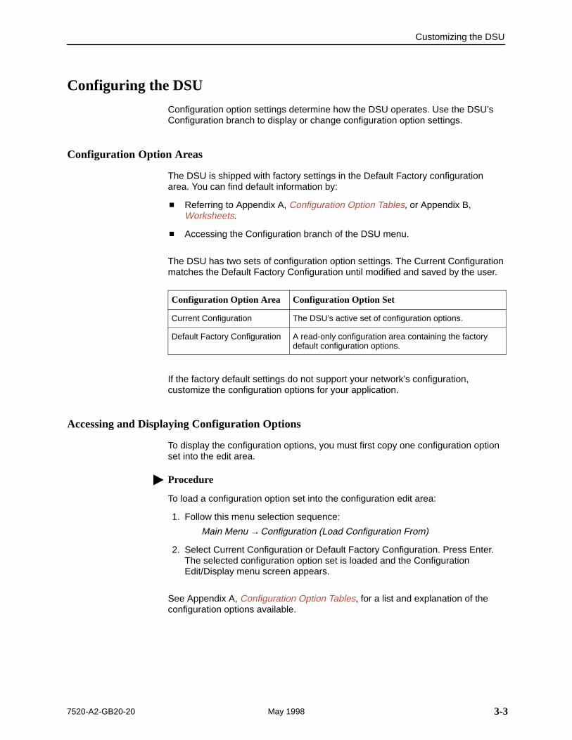
Configuration option settings determine how the DSU operates. Use the DSU’sConfiguration branch to display or change configuration option settings.
Configuration Option Areas
The DSU is shipped with factory settings in the Default Factory configurationarea. You can find default information by:
� Referring to Appendix A, Configuration Option Tables, or Appendix B,Worksheets.
� Accessing the Configuration branch of the DSU menu.
The DSU has two sets of configuration option settings. The Current Configurationmatches the Default Factory Configuration until modified and saved by the user.
Configuration Option Area Configuration Option Set
Current Configuration The DSU’s active set of configuration options.
Default Factory Configuration A read-only configuration area containing the factorydefault configuration options.
If the factory default settings do not support your network’s configuration,customize the configuration options for your application.
Accessing and Displaying Configuration Options
To display the configuration options, you must first copy one configuration optionset into the edit area.
� Procedure
To load a configuration option set into the configuration edit area:
1. Follow this menu selection sequence:
Main Menu →Configuration (Load Configuration From)
2. Select Current Configuration or Default Factory Configuration. Press Enter.The selected configuration option set is loaded and the ConfigurationEdit/Display menu screen appears.
See Appendix A, Configuration Option Tables, for a list and explanation of theconfiguration options available.

Customizing the DSU
3-4 7520-A2-GB20-20May 1998
This page intentionally left blank.
4-17520-A2-GB20-20 May 1998
Monitoring the DSU
4What to Monitor
This chapter presents information on how to access and monitor DSU status andperformance statistics on the DDS network. You can monitor DSU operations byviewing:
� System and Test Status screen
� Highest priority Health and Status message on the last line of all screens
� Network Interface Status screen
� Network Performance Statistics screen
� LEDs on the ATI Status screen or the DSU’s front panel
Table 4-1 shows the available indicators of alarm conditions on the networkinterface and the User Data port.
Table 4-1. Alarm Indicator Locations
Alarm ConditionStatusScreen
SpecificLED
Crossed Pairs Y N
No Signal (NS) Y Y
Out of Service (OOS) Y Y
Out of Frame (OOF) Y Y
Excessive Bipolar Violations (BPV) Y N
Monitoring the DSU
4-2 7520-A2-GB20-20May 1998
Viewing System and Test Status
To view System and Test Status information, follow this menu selectionsequence:
Main Menu →Status → System and Test Status
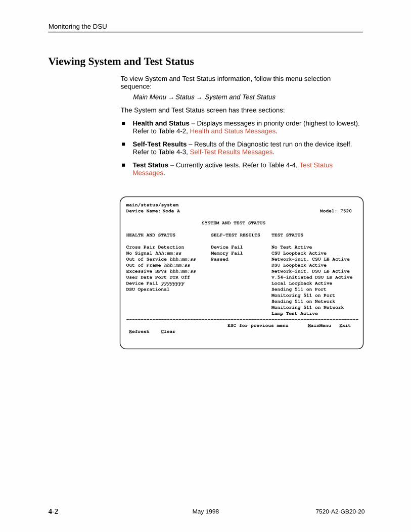
The System and Test Status screen has three sections:
� Health and Status – Displays messages in priority order (highest to lowest).Refer to Table 4-2, Health and Status Messages.
� Self-Test Results – Results of the Diagnostic test run on the device itself.Refer to Table 4-3, Self-Test Results Messages.
� Test Status – Currently active tests. Refer to Table 4-4, Test StatusMessages.
ÎÎÎÎÎÎÎÎÎÎÎÎÎÎÎÎÎÎÎÎÎÎÎÎÎÎÎÎÎÎÎÎÎÎÎÎÎÎÎÎÎÎÎÎÎÎÎÎÎÎÎÎÎÎÎÎÎÎÎÎÎÎÎÎÎÎÎÎÎÎÎÎÎÎÎÎÎÎÎÎÎÎÎÎÎÎÎÎÎÎÎÎÎÎÎÎÎÎÎÎÎÎÎÎÎÎÎÎÎÎÎÎÎÎÎÎÎÎÎÎÎÎÎÎÎÎÎÎÎÎÎÎÎÎÎÎÎÎÎÎÎÎÎÎÎÎÎÎÎÎÎÎÎÎÎÎÎÎÎÎÎÎÎÎÎÎÎÎÎÎÎÎÎÎÎÎÎÎÎÎÎÎÎÎÎÎÎÎÎÎÎÎÎÎÎÎÎÎÎÎÎÎÎÎÎÎÎÎÎÎÎÎÎÎÎÎÎÎÎÎÎÎÎÎÎÎÎÎÎÎÎÎÎÎÎÎÎÎÎÎÎÎÎÎÎÎÎÎÎÎÎÎÎÎÎÎÎÎÎÎÎÎÎÎÎÎÎÎÎÎÎÎÎÎÎÎÎÎÎÎÎÎÎÎÎÎÎÎÎÎÎÎÎÎÎÎÎÎÎÎÎÎÎÎÎÎÎÎÎÎÎÎÎÎÎÎÎÎÎÎÎÎÎÎÎÎÎÎÎÎÎÎÎÎÎÎÎÎÎÎÎÎÎÎÎÎÎÎÎÎÎÎÎÎÎÎÎÎÎÎÎÎÎÎÎÎÎÎÎÎÎÎÎÎÎ
main/status/systemDevice Name: Node A Model: 7520
SYSTEM AND TEST STATUS
HEALTH AND STATUS SELF-TEST RESULTS TEST STATUS
Cross Pair Detection Device Fail No Test ActiveNo Signal hhh:mm:ss Memory Fail CSU Loopback ActiveOut of Service hhh:mm:ss Passed Network-init. CSU LB ActiveOut of Frame hhh:mm:ss DSU Loopback ActiveExcessive BPVs hhh:mm:ss Network-init. DSU LB ActiveUser Data Port DTR Off V.54-initiated DSU LB ActiveDevice Fail yyyyyyyy Local Loopback ActiveDSU Operational Sending 511 on Port
Monitoring 511 on PortSending 511 on NetworkMonitoring 511 on NetworkLamp Test Active
–––––––––––––––––––––––––––––––––––––––––––––––––––––––––––––––––––––––––––––––– ESC for previous menu M ainMenu E xit R efresh C lear
Monitoring the DSU
4-37520-A2-GB20-20 May 1998
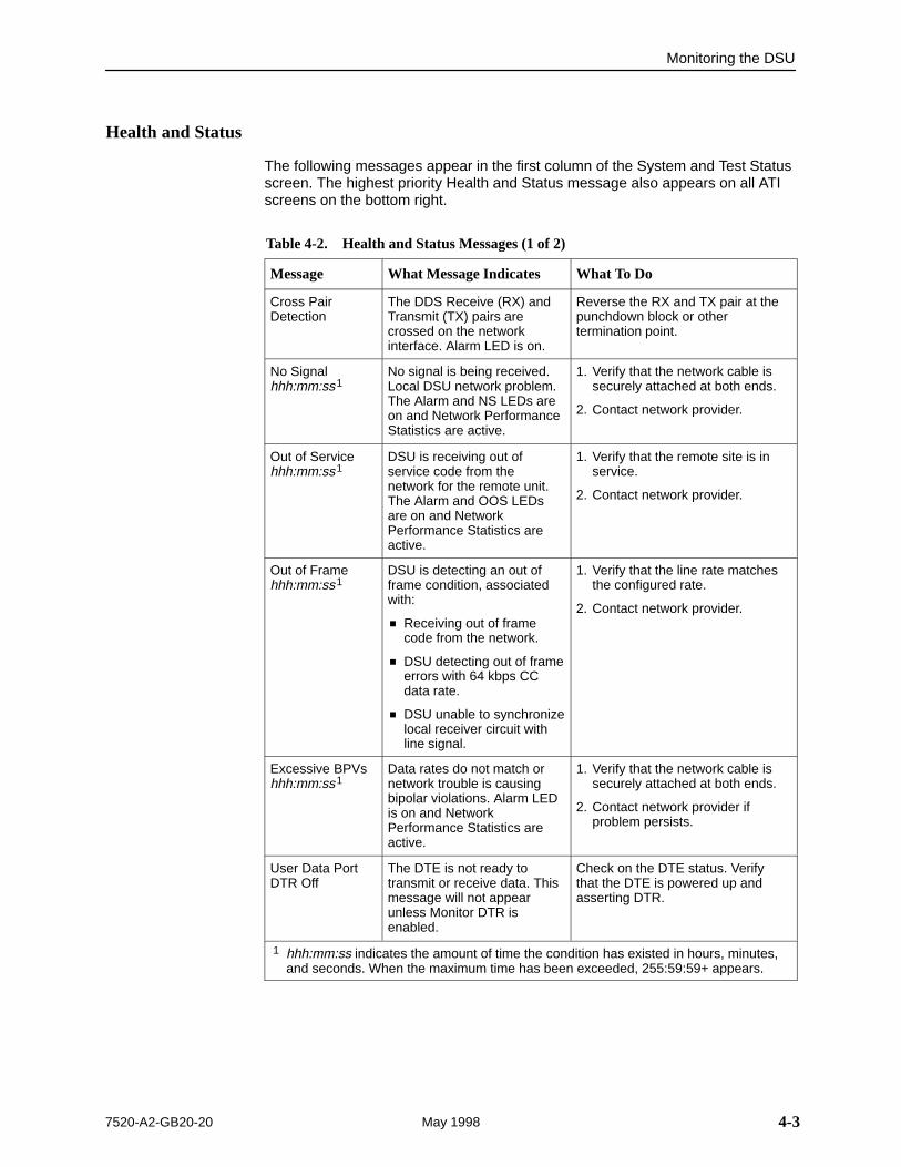
Health and Status
The following messages appear in the first column of the System and Test Statusscreen. The highest priority Health and Status message also appears on all ATIscreens on the bottom right.
Table 4-2. Health and Status Messages (1 of 2)
Message What Message Indicates What To Do
Cross PairDetection
The DDS Receive (RX) andTransmit (TX) pairs arecrossed on the networkinterface. Alarm LED is on.
Reverse the RX and TX pair at thepunchdown block or othertermination point.
No Signalhhh:mm:ss1
No signal is being received.Local DSU network problem.The Alarm and NS LEDs areon and Network PerformanceStatistics are active.
1. Verify that the network cable issecurely attached at both ends.
2. Contact network provider.
Out of Servicehhh:mm:ss1
DSU is receiving out ofservice code from thenetwork for the remote unit.The Alarm and OOS LEDsare on and NetworkPerformance Statistics areactive.
1. Verify that the remote site is inservice.
2. Contact network provider.
Out of Framehhh:mm:ss1
DSU is detecting an out offrame condition, associatedwith:
� Receiving out of framecode from the network.
� DSU detecting out of frameerrors with 64 kbps CCdata rate.
� DSU unable to synchronizelocal receiver circuit withline signal.
1. Verify that the line rate matchesthe configured rate.
2. Contact network provider.
Excessive BPVshhh:mm:ss1
Data rates do not match ornetwork trouble is causingbipolar violations. Alarm LEDis on and NetworkPerformance Statistics areactive.
1. Verify that the network cable issecurely attached at both ends.
2. Contact network provider ifproblem persists.
User Data PortDTR Off
The DTE is not ready totransmit or receive data. Thismessage will not appearunless Monitor DTR isenabled.
Check on the DTE status. Verifythat the DTE is powered up andasserting DTR.
1 hhh:mm:ss indicates the amount of time the condition has existed in hours, minutes,and seconds. When the maximum time has been exceeded, 255:59:59+ appears.
Monitoring the DSU
4-4 7520-A2-GB20-20May 1998
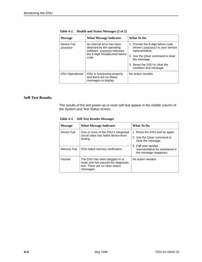
Table 4-2. Health and Status Messages (2 of 2)
Message What To DoWhat Message Indicates
Device Failyyyyyyyy
An internal error has beendetected by the operatingsoftware. yyyyyyyy indicatesthe 8-digit hexadecimal failurecode.
1. Provide the 8-digit failure codeshown (yyyyyyyy ) to your servicerepresentative.
2. Use the Clear command to clearthe message.
3. Reset the DSU to clear thecondition and message.
DSU Operational DSU is functioning properlyand there are no statusmessages to display.
No action needed.
Self-Test Results
The results of the last power-up or reset self-test appear in the middle column ofthe System and Test Status screen.
Table 4-3. Self-Test Results Messages
Message What Message Indicates What To Do
Device Fail One or more of the DSU’s integratedcircuit chips has failed device-leveltesting.
1. Reset the DSU and try again.
2. Use the Clear command toclear the message.
3 Call your serviceMemory Fail DSU failed memory verification.
3. Call your servicerepresentative for assistance ifthe message reappears.
Passed The DSU has been plugged in orreset and has passed the diagnostictest. There are no other statusmessages.
No action needed.
Monitoring the DSU
4-57520-A2-GB20-20 May 1998
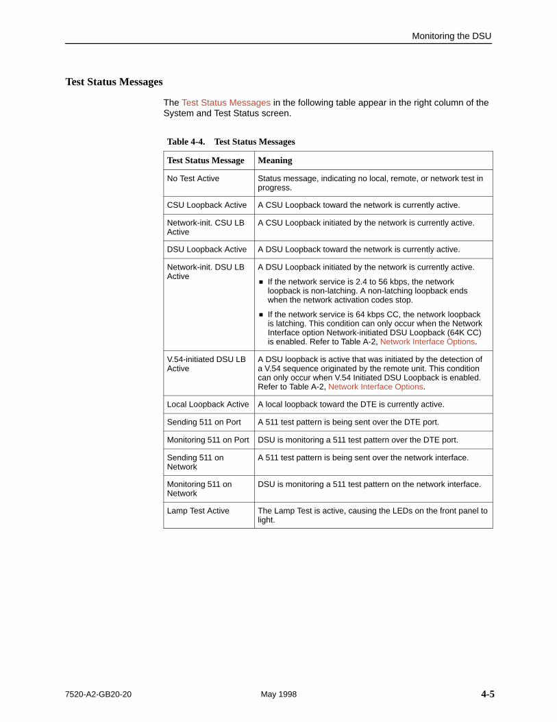
Test Status Messages
The Test Status Messages in the following table appear in the right column of theSystem and Test Status screen.
Table 4-4. Test Status Messages
Test Status Message Meaning
No Test Active Status message, indicating no local, remote, or network test inprogress.
CSU Loopback Active A CSU Loopback toward the network is currently active.
Network-init. CSU LBActive
A CSU Loopback initiated by the network is currently active.
DSU Loopback Active A DSU Loopback toward the network is currently active.
Network-init. DSU LBActive
A DSU Loopback initiated by the network is currently active.
� If the network service is 2.4 to 56 kbps, the networkloopback is non-latching. A non-latching loopback endswhen the network activation codes stop.
� If the network service is 64 kbps CC, the network loopbackis latching. This condition can only occur when the NetworkInterface option Network-initiated DSU Loopback (64K CC)is enabled. Refer to Table A-2, Network Interface Options.
V.54-initiated DSU LBActive
A DSU loopback is active that was initiated by the detection ofa V.54 sequence originated by the remote unit. This conditioncan only occur when V.54 Initiated DSU Loopback is enabled.Refer to Table A-2, Network Interface Options.
Local Loopback Active A local loopback toward the DTE is currently active.
Sending 511 on Port A 511 test pattern is being sent over the DTE port.
Monitoring 511 on Port DSU is monitoring a 511 test pattern over the DTE port.
Sending 511 onNetwork
A 511 test pattern is being sent over the network interface.
Monitoring 511 onNetwork
DSU is monitoring a 511 test pattern on the network interface.
Lamp Test Active The Lamp Test is active, causing the LEDs on the front panel tolight.
Monitoring the DSU
4-6 7520-A2-GB20-20May 1998
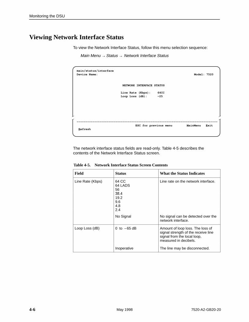
Viewing Network Interface Status
To view the Network Interface Status, follow this menu selection sequence:
Main Menu →Status → Network Interface Status
main/status/interfaceDevice Name: Model: 7520
NETWORK INTERFACE STATUS
Line Rate (Kbps): 64CCLoop Loss (dB): –25
––––––––––––––––––––––––––––––––––––––––––––––––––––––––––––––––––––––––––––––––ESC for previous menu M ainMenu E xit
R efresh
ÎÎ
ÎÎÎÎ
The network interface status fields are read-only. Table 4-5 describes thecontents of the Network Interface Status screen.
Table 4-5. Network Interface Status Screen Contents
Field Status What the Status Indicates
Line Rate (Kbps) 64 CC64 LADS5638 4
Line rate on the network interface.
38.419.29.64.82 4
82.4
No Signal No signal can be detected over thenetwork interface.
Loop Loss (dB) 0 to –65 dB Amount of loop loss. The loss ofsignal strength of the receive linesignal from the local loop,measured in decibels.
Inoperative The line may be disconnected.
Monitoring the DSU
4-77520-A2-GB20-20 May 1998
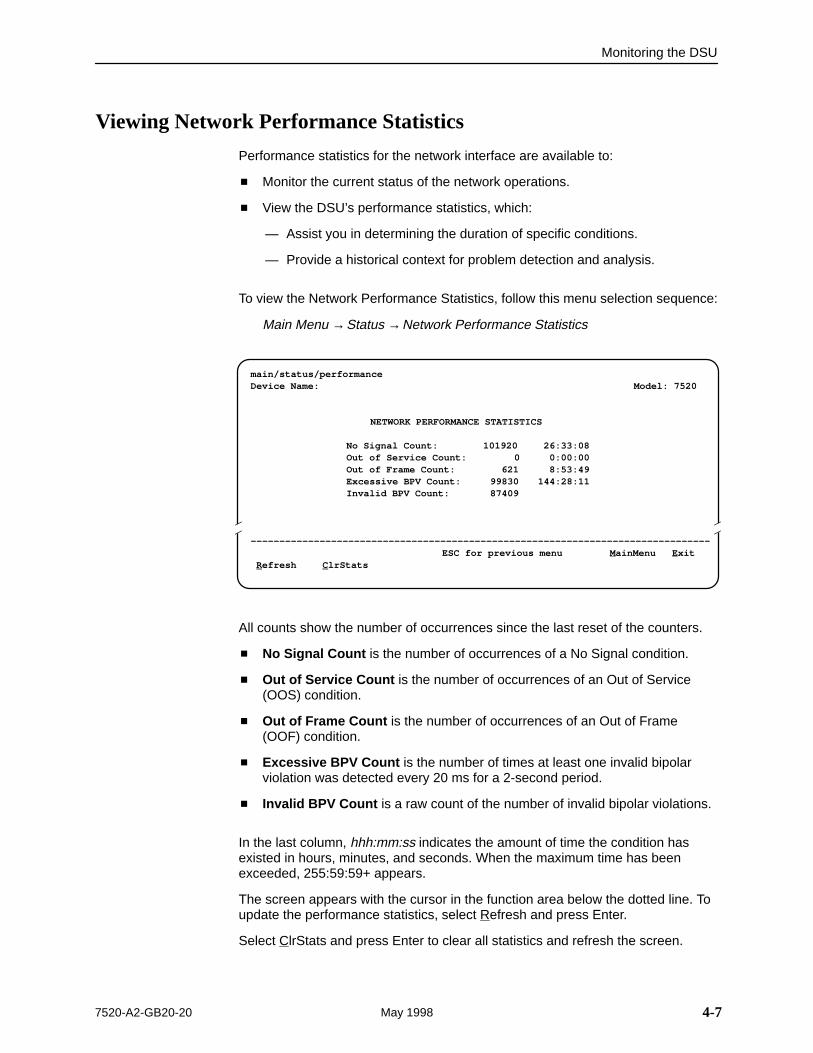
Viewing Network Performance Statistics
Performance statistics for the network interface are available to:
� Monitor the current status of the network operations.
� View the DSU’s performance statistics, which:
— Assist you in determining the duration of specific conditions.
— Provide a historical context for problem detection and analysis.
To view the Network Performance Statistics, follow this menu selection sequence:
Main Menu →Status →Network Performance Statistics
main/status/performanceDevice Name: Model: 7520
NETWORK PERFORMANCE STATISTICS
No Signal Count: 101920 26:33:08Out of Service Count: 0 0:00:00Out of Frame Count: 621 8:53:49Excessive BPV Count: 99830 144:28:11Invalid BPV Count: 87409
––––––––––––––––––––––––––––––––––––––––––––––––––––––––––––––––––––––––––––––––ESC for previous menu M ainMenu E xit
R efresh C lrStats
ÎÎ
ÎÎÎÎ
All counts show the number of occurrences since the last reset of the counters.
� No Signal Count is the number of occurrences of a No Signal condition.
� Out of Service Count is the number of occurrences of an Out of Service(OOS) condition.
� Out of Frame Count is the number of occurrences of an Out of Frame(OOF) condition.
� Excessive BPV Count is the number of times at least one invalid bipolarviolation was detected every 20 ms for a 2-second period.
� Invalid BPV Count is a raw count of the number of invalid bipolar violations.
In the last column, hhh:mm:ss indicates the amount of time the condition hasexisted in hours, minutes, and seconds. When the maximum time has beenexceeded, 255:59:59+ appears.
The screen appears with the cursor in the function area below the dotted line. Toupdate the performance statistics, select Refresh and press Enter.
Select ClrStats and press Enter to clear all statistics and refresh the screen.
Monitoring the DSU
4-8 7520-A2-GB20-20May 1998
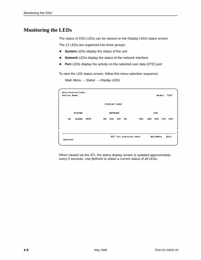
Monitoring the LEDs
The status of DSU LEDs can be viewed on the Display LEDs status screen.
The 12 LEDs are organized into three groups:
� System LEDs display the status of the unit
� Network LEDs display the status of the network interface
� Port LEDs display the activity on the selected user data (DTE) port
To view the LED status screen, follow this menu selection sequence:
Main Menu →Status → Display LEDs
main/status/ledsDevice Name: Model: 7520
DISPLAY LEDS
SYSTEM NETWORK DTE
OK ALARM TEST DM OOS OOF NS TXD RXD RTS CTS DTR
–––––––––––––––––––––––––––––––––––––––––––––––––––––––––––––––––––––––––––––––– ESC for previous menu M ainMenu E xit
R efresh
ÎÎ
ÎÎÎÎ
When viewed via the ATI, the status display screen is updated approximatelyevery 5 seconds. Use Refresh to obtain a current status of all LEDs.
Monitoring the DSU
4-97520-A2-GB20-20 May 1998
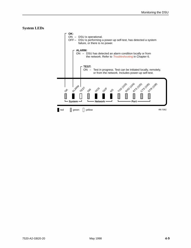
System LEDs
496-15062
CTS (106
)
OK ALARM
TESTDM OOS
OOFNS TXD (1
03)
RXD (104
)
RTS (105
)
DTR (108
)
NetworkSystem Port
red green yellow
OK:ON – DSU is operational.OFF – DSU is performing a power-up self-test, has detected a system
failure, or there is no power.
ALARM:ON – DSU has detected an alarm condition locally or from
the network. Refer to Troubleshooting in Chapter 6.
TEST:ON – Test in progress. Test can be initiated locally, remotely,
or from the network. Includes power-up self-test.
Monitoring the DSU
4-10 7520-A2-GB20-20May 1998
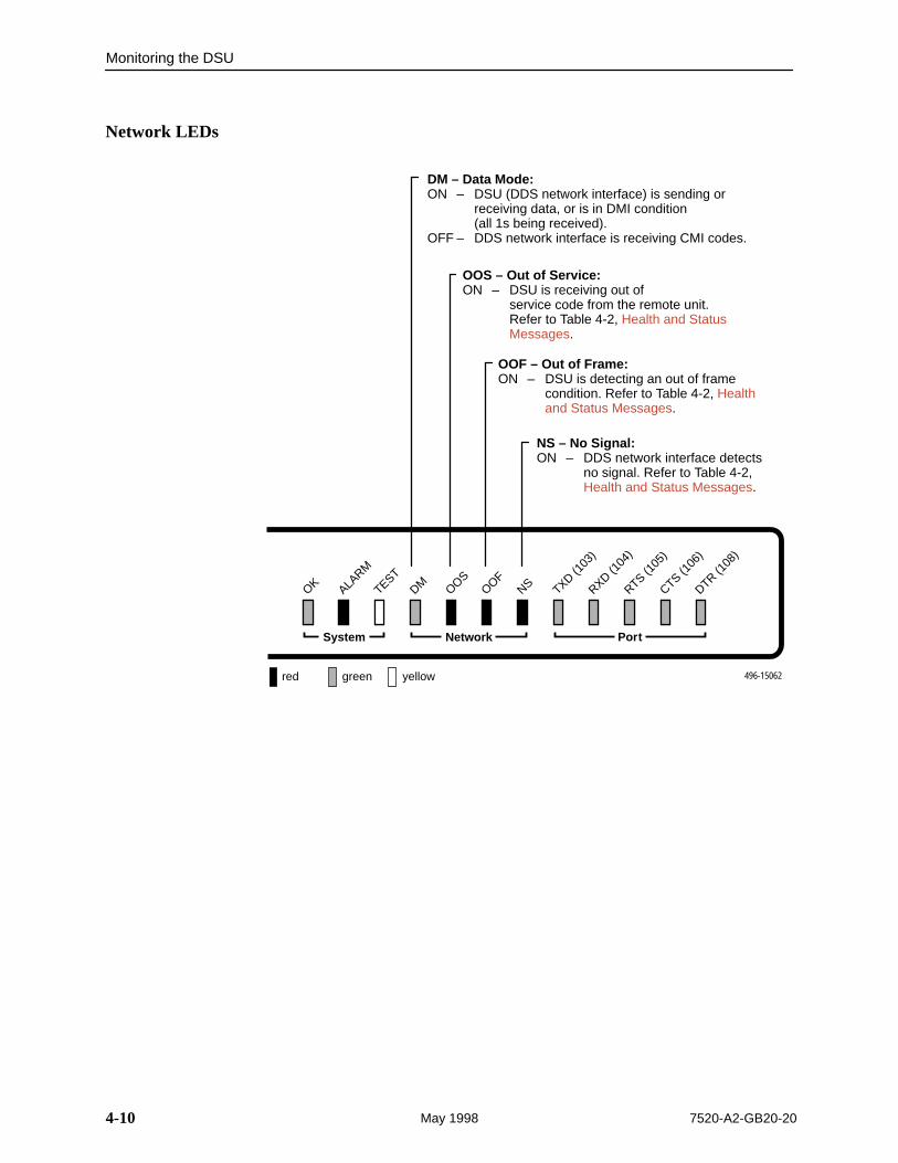
Network LEDs
496-15062
CTS (106
)
OK ALARM
TESTDM OOS
OOFNS TXD (1
03)
RXD (104
)
RTS (105
)
DTR (108
)
NetworkSystem Port
red green yellow
DM – Data Mode:ON – DSU (DDS network interface) is sending or
receiving data, or is in DMI condition (all 1s being received).
OFF – DDS network interface is receiving CMI codes.
OOS – Out of Service:ON – DSU is receiving out of
service code from the remote unit.Refer to Table 4-2, Health and Status Messages.
OOF – Out of Frame:ON – DSU is detecting an out of frame
condition. Refer to Table 4-2, Health and Status Messages.
NS – No Signal:ON – DDS network interface detects
no signal. Refer to Table 4-2, Health and Status Messages.
Monitoring the DSU
4-117520-A2-GB20-20 May 1998
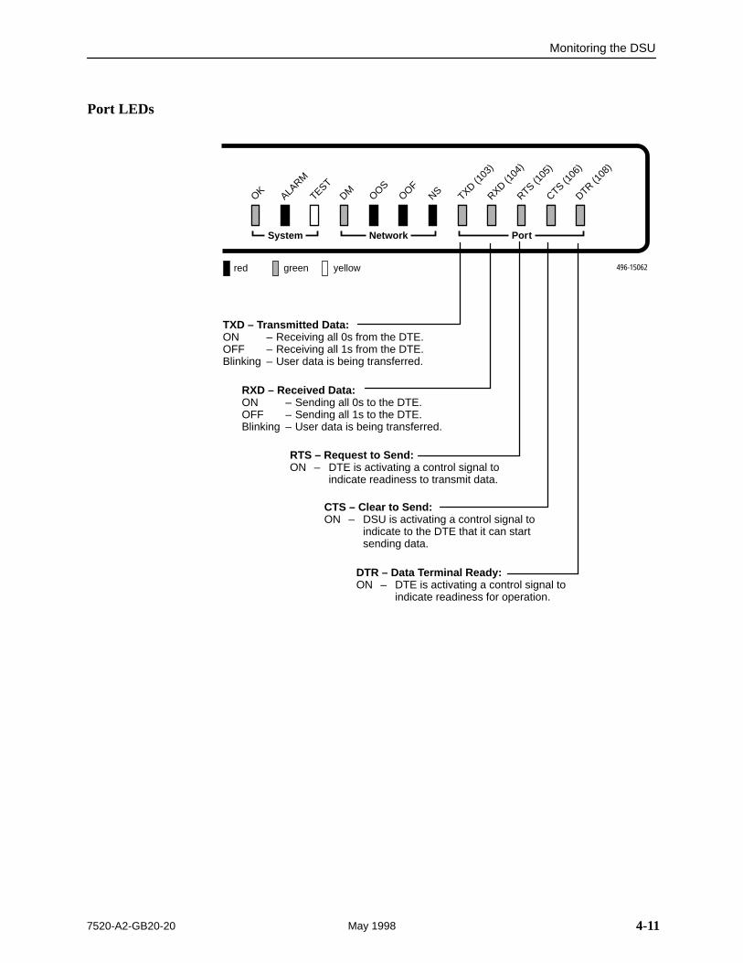
Port LEDs
496-15062
CTS (106
)
OK ALARM
TESTDM OOS
OOFNS TXD (1
03)
RXD (104
)
RTS (105
)
DTR (108
)
NetworkSystem Port
red green yellow
TXD – Transmitted Data:ON – Receiving all 0s from the DTE.OFF – Receiving all 1s from the DTE.Blinking – User data is being transferred.
RXD – Received Data:ON – Sending all 0s to the DTE.OFF – Sending all 1s to the DTE.Blinking – User data is being transferred.
RTS – Request to Send:ON – DTE is activating a control signal to
indicate readiness to transmit data.
CTS – Clear to Send:ON – DSU is activating a control signal to
indicate to the DTE that it can startsending data.
DTR – Data Terminal Ready:ON – DTE is activating a control signal to
indicate readiness for operation.

Monitoring the DSU
4-12 7520-A2-GB20-20May 1998
This page intentionally left blank.
5-17520-A2-GB20-20 May 1998
Testing
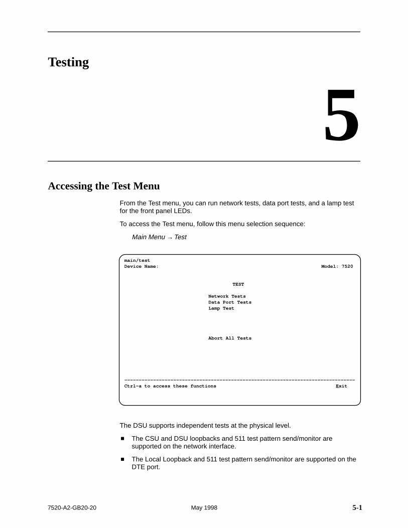
5Accessing the Test Menu
From the Test menu, you can run network tests, data port tests, and a lamp testfor the front panel LEDs.
To access the Test menu, follow this menu selection sequence:
Main Menu →Test
ÎÎÎÎÎÎÎÎÎÎÎÎÎÎÎÎÎÎÎÎÎÎÎÎÎÎÎÎÎÎÎÎÎÎÎÎÎÎÎÎÎÎÎÎÎÎÎÎÎÎÎÎÎÎÎÎÎÎÎÎÎÎÎÎÎÎÎÎÎÎÎÎÎÎÎÎÎÎÎÎÎÎÎÎÎÎÎÎÎÎÎÎÎÎÎÎÎÎÎÎÎÎÎÎÎÎÎÎÎÎÎÎÎÎÎÎÎÎÎÎÎÎÎÎÎÎÎÎÎÎÎÎÎÎÎÎÎÎÎÎÎÎÎÎÎÎÎÎÎÎÎÎÎÎÎÎÎÎÎÎÎÎÎÎÎÎÎÎÎÎÎÎÎÎÎÎÎÎÎÎÎÎÎÎÎÎÎÎÎÎÎÎÎÎÎÎÎÎÎÎÎÎÎÎÎÎÎÎÎÎÎÎÎÎÎÎÎÎÎÎÎÎÎÎÎÎÎÎÎÎÎÎÎÎÎÎÎÎÎÎÎÎÎÎÎÎÎÎÎÎÎÎÎÎÎÎÎÎÎÎÎÎÎÎÎÎÎÎÎÎÎÎÎÎÎÎÎÎÎÎÎÎÎÎÎÎÎÎÎÎÎÎÎÎÎÎÎÎÎÎÎÎÎÎÎÎÎÎÎÎÎÎÎÎÎÎÎÎÎÎÎÎÎÎÎÎÎÎÎÎÎÎÎÎÎÎÎÎÎÎÎÎÎÎÎÎÎÎÎÎÎÎÎÎÎÎÎÎÎÎÎÎÎÎÎÎÎÎÎÎÎÎÎÎÎÎÎÎÎÎÎÎÎÎÎÎÎÎÎÎÎÎÎÎÎÎÎÎÎÎ
main/testDevice Name: Model: 7520
TEST
Network TestsData Port TestsLamp Test
Abort All Tests
––––––––––––––––––––––––––––––––––––––––––––––––––––––––––––––––––––––––––––––––Ctrl-a to access these functions E xit
The DSU supports independent tests at the physical level.
� The CSU and DSU loopbacks and 511 test pattern send/monitor aresupported on the network interface.
� The Local Loopback and 511 test pattern send/monitor are supported on theDTE port.
Testing
5-2 7520-A2-GB20-20May 1998
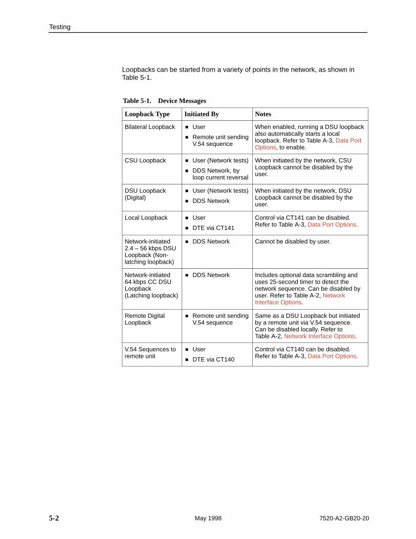
Loopbacks can be started from a variety of points in the network, as shown inTable 5-1.
Table 5-1. Device Messages
Loopback Type Initiated By Notes
Bilateral Loopback � User
� Remote unit sendingV.54 sequence
When enabled, running a DSU loopbackalso automatically starts a localloopback. Refer to Table A-3, Data PortOptions, to enable.
CSU Loopback � User (Network tests)
� DDS Network, byloop current reversal
When initiated by the network, CSULoopback cannot be disabled by theuser.
DSU Loopback(Digital)
� User (Network tests)
� DDS Network
When initiated by the network, DSULoopback cannot be disabled by theuser.
Local Loopback � User
� DTE via CT141
Control via CT141 can be disabled.Refer to Table A-3, Data Port Options.
Network-initiated 2.4 – 56 kbps DSULoopback (Non-latching loopback)
� DDS Network Cannot be disabled by user.
Network-initiated 64 kbps CC DSULoopback(Latching loopback)
� DDS Network Includes optional data scrambling anduses 25-second timer to detect thenetwork sequence. Can be disabled byuser. Refer to Table A-2, NetworkInterface Options.
Remote DigitalLoopback
� Remote unit sendingV.54 sequence
Same as a DSU Loopback but initiatedby a remote unit via V.54 sequence.Can be disabled locally. Refer to Table A-2, Network Interface Options.
V.54 Sequences toremote unit
� User
� DTE via CT140
Control via CT140 can be disabled.Refer to Table A-3, Data Port Options.
Testing
5-37520-A2-GB20-20 May 1998
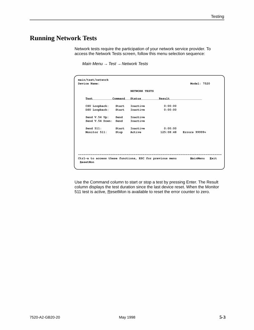
Running Network Tests
Network tests require the participation of your network service provider. Toaccess the Network Tests screen, follow this menu selection sequence:
Main Menu →Test →Network Tests
ÎÎÎÎÎÎÎÎÎÎÎÎÎÎÎÎÎÎÎÎÎÎÎÎÎÎÎÎÎÎÎÎÎÎÎÎÎÎÎÎÎÎÎÎÎÎÎÎÎÎÎÎÎÎÎÎÎÎÎÎÎÎÎÎÎÎÎÎÎÎÎÎÎÎÎÎÎÎÎÎÎÎÎÎÎÎÎÎÎÎÎÎÎÎÎÎÎÎÎÎÎÎÎÎÎÎÎÎÎÎÎÎÎÎÎÎÎÎÎÎÎÎÎÎÎÎÎÎÎÎÎÎÎÎÎÎÎÎÎÎÎÎÎÎÎÎÎÎÎÎÎÎÎÎÎÎÎÎÎÎÎÎÎÎÎÎÎÎÎÎÎÎÎÎÎÎÎÎÎÎÎÎÎÎÎÎÎÎÎÎÎÎÎÎÎÎÎÎÎÎÎÎÎÎÎÎÎÎÎÎÎÎÎÎÎÎÎÎÎÎÎÎÎÎÎÎÎÎÎÎÎÎÎÎÎÎÎÎÎÎÎÎÎÎÎÎÎÎÎÎÎÎÎÎÎÎÎÎÎÎÎÎÎÎÎÎÎÎÎÎÎÎÎÎÎÎÎÎÎÎÎÎÎÎÎÎÎÎÎÎÎÎÎÎÎÎÎÎÎÎÎÎÎÎÎÎÎÎÎÎÎÎÎÎÎÎÎÎÎÎÎÎÎÎÎÎÎÎÎÎÎÎÎÎÎÎÎÎÎÎÎÎÎÎÎÎÎÎÎÎÎÎÎÎÎÎÎÎÎÎÎÎÎÎÎÎÎÎÎÎÎÎÎÎÎÎÎÎÎÎÎÎÎÎÎÎÎÎÎÎÎÎÎÎÎÎÎÎÎÎ
main/test/networkDevice Name: Model: 7520
NETWORK TESTS
Test Command Status Result
CSU Loopback: Start Inactive 0:00:00DSU Loopback: Start Inactive 0:00:00
Send V.54 Up: Send InactiveSend V.54 Down: Send Inactive
Send 511: Start Inactive 0:00:00Monitor 511: Stop Active 125:08:48 Errors 99999+
––––––––––––––––––––––––––––––––––––––––––––––––––––––––––––––––––––––––––––––––Ctrl-a to access these functions, ESC for previous menu M ainMenu E xit R esetMon
Use the Command column to start or stop a test by pressing Enter. The Resultcolumn displays the test duration since the last device reset. When the Monitor511 test is active, ResetMon is available to reset the error counter to zero.
Testing
5-4 7520-A2-GB20-20May 1998
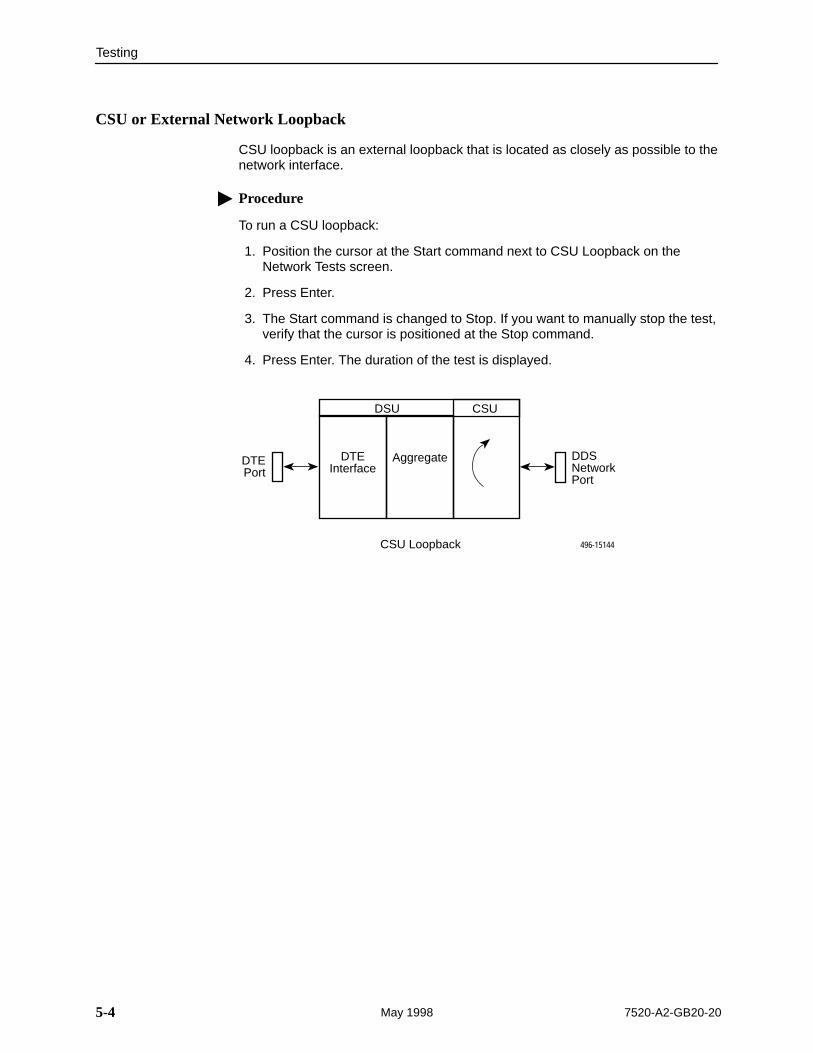
CSU or External Network Loopback
CSU loopback is an external loopback that is located as closely as possible to thenetwork interface.
� Procedure
To run a CSU loopback:
1. Position the cursor at the Start command next to CSU Loopback on theNetwork Tests screen.
2. Press Enter.
3. The Start command is changed to Stop. If you want to manually stop the test,verify that the cursor is positioned at the Stop command.
4. Press Enter. The duration of the test is displayed.
DSU CSU
DTEInterface
AggregateDTEPort
DDSNetworkPort
496-15144CSU Loopback
Testing
5-57520-A2-GB20-20 May 1998
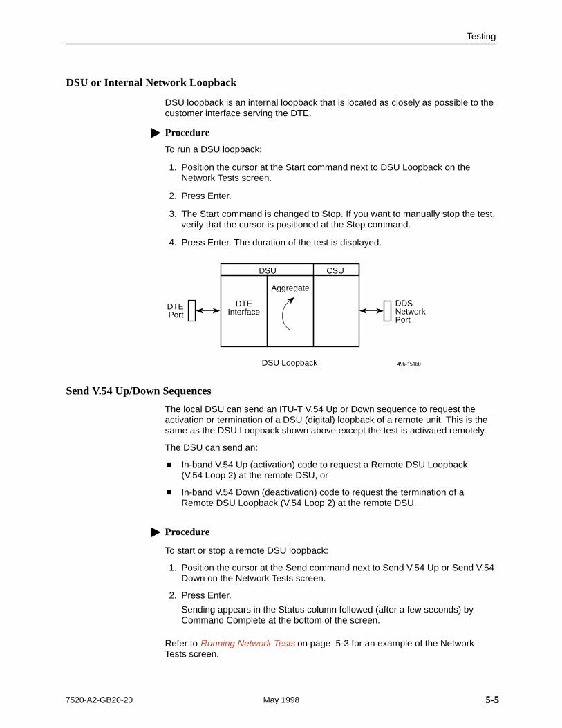
DSU or Internal Network Loopback
DSU loopback is an internal loopback that is located as closely as possible to thecustomer interface serving the DTE.
� Procedure
To run a DSU loopback:
1. Position the cursor at the Start command next to DSU Loopback on theNetwork Tests screen.
2. Press Enter.
3. The Start command is changed to Stop. If you want to manually stop the test,verify that the cursor is positioned at the Stop command.
4. Press Enter. The duration of the test is displayed.
DSU CSU
DTEInterface
Aggregate
DTEPort
DDSNetworkPort
496-15160DSU Loopback
Send V.54 Up/Down Sequences
The local DSU can send an ITU-T V.54 Up or Down sequence to request theactivation or termination of a DSU (digital) loopback of a remote unit. This is thesame as the DSU Loopback shown above except the test is activated remotely.
The DSU can send an:
� In-band V.54 Up (activation) code to request a Remote DSU Loopback (V.54 Loop 2) at the remote DSU, or
� In-band V.54 Down (deactivation) code to request the termination of aRemote DSU Loopback (V.54 Loop 2) at the remote DSU.
� Procedure
To start or stop a remote DSU loopback:
1. Position the cursor at the Send command next to Send V.54 Up or Send V.54Down on the Network Tests screen.
2. Press Enter.
Sending appears in the Status column followed (after a few seconds) byCommand Complete at the bottom of the screen.
Refer to Running Network Tests on page 5-3 for an example of the NetworkTests screen.
Testing
5-6 7520-A2-GB20-20May 1998
511 Test Pattern for the Network
This test sends or monitors the 511 test pattern over the network interface.
� Procedure
To run a Send 511 test:
1. Position the cursor at the Start command next to Send 511 on the NetworkTests screen.
2. Press Enter.
3. The Start command is changed to Stop. If you want to manually stop the test,verify that the cursor is positioned at the Stop command.
4. Press Enter. The duration of the test is displayed.
� Procedure
To run a Monitor 511 test:
1. Position the cursor at the Start command next to Monitor 511 on the NetworkTests screen.
2. If desired, use Ctrl-a to switch to the screen function key area and use thevirtual function key r or R (ResetMon) to clear the error counter to zero. PressCtrl-a to return the cursor to the Start command.
3. Press Enter.
4. The Start command is changed to Stop. If you want to manually stop the test,verify that the cursor is positioned at the Stop command.
5. Press Enter. The duration of the test is displayed.
Refer to Running Network Tests on page 5-3 for an example of the NetworkTests screen.
Testing
5-77520-A2-GB20-20 May 1998
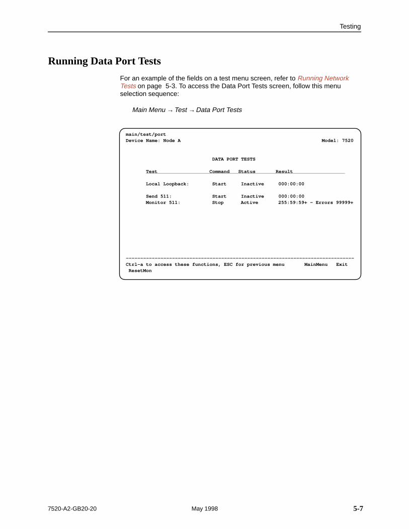
Running Data Port Tests
For an example of the fields on a test menu screen, refer to Running NetworkTests on page 5-3. To access the Data Port Tests screen, follow this menuselection sequence:
Main Menu →Test →Data Port Tests
ÎÎÎÎÎÎÎÎÎÎÎÎÎÎÎÎÎÎÎÎÎÎÎÎÎÎÎÎÎÎÎÎÎÎÎÎÎÎÎÎÎÎÎÎÎÎÎÎÎÎÎÎÎÎÎÎÎÎÎÎÎÎÎÎÎÎÎÎÎÎÎÎÎÎÎÎÎÎÎÎÎÎÎÎÎÎÎÎÎÎÎÎÎÎÎÎÎÎÎÎÎÎÎÎÎÎÎÎÎÎÎÎÎÎÎÎÎÎÎÎÎÎÎÎÎÎÎÎÎÎÎÎÎÎÎÎÎÎÎÎÎÎÎÎÎÎÎÎÎÎÎÎÎÎÎÎÎÎÎÎÎÎÎÎÎÎÎÎÎÎÎÎÎÎÎÎÎÎÎÎÎÎÎÎÎÎÎÎÎÎÎÎÎÎÎÎÎÎÎÎÎÎÎÎÎÎÎÎÎÎÎÎÎÎÎÎÎÎÎÎÎÎÎÎÎÎÎÎÎÎÎÎÎÎÎÎÎÎÎÎÎÎÎÎÎÎÎÎÎÎÎÎÎÎÎÎÎÎÎÎÎÎÎÎÎÎÎÎÎÎÎÎÎÎÎÎÎÎÎÎÎÎÎÎÎÎÎÎÎÎÎÎÎÎÎÎÎÎÎÎÎÎÎÎÎÎÎÎÎÎÎÎÎÎÎÎÎÎÎÎÎÎÎÎÎÎÎÎÎÎÎÎÎÎÎÎÎÎÎÎÎÎÎÎÎÎÎÎÎÎÎÎÎÎÎÎÎÎÎÎÎÎÎÎÎÎÎÎÎÎÎÎÎÎÎÎÎÎÎÎÎÎÎÎÎÎÎÎÎÎÎÎÎÎÎÎÎÎÎÎ
main/test/port Device Name: Node A Model: 7520
DATA PORT TESTS
Test Command Status Result
Local Loopback: Start Inactive 000:00:00
Send 511: Start Inactive 000:00:00 Monitor 511: Stop Active 255:59:59+ – Errors 99999+
–––––––––––––––––––––––––––––––––––––––––––––––––––––––––––––––––––––––––––––––Ctrl–a to access these functions, ESC for previous menu MainMenu Exit ResetMon
Testing
5-8 7520-A2-GB20-20May 1998
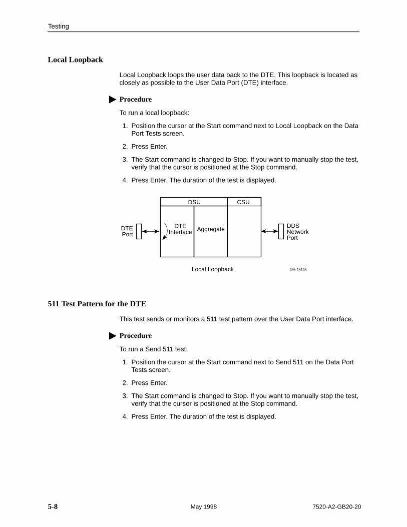
Local Loopback
Local Loopback loops the user data back to the DTE. This loopback is located asclosely as possible to the User Data Port (DTE) interface.
� Procedure
To run a local loopback:
1. Position the cursor at the Start command next to Local Loopback on the DataPort Tests screen.
2. Press Enter.
3. The Start command is changed to Stop. If you want to manually stop the test,verify that the cursor is positioned at the Stop command.
4. Press Enter. The duration of the test is displayed.
DSU CSU
DTEInterface Aggregate DDS
NetworkPort
496-15145
DTEPort
Local Loopback
511 Test Pattern for the DTE
This test sends or monitors a 511 test pattern over the User Data Port interface.
� Procedure
To run a Send 511 test:
1. Position the cursor at the Start command next to Send 511 on the Data PortTests screen.
2. Press Enter.
3. The Start command is changed to Stop. If you want to manually stop the test,verify that the cursor is positioned at the Stop command.
4. Press Enter. The duration of the test is displayed.
Testing
5-97520-A2-GB20-20 May 1998
� Procedure
To run a Monitor 511 test:
1. Position the cursor at the Start command next to Monitor 511 on the DataPort Tests screen.
2. If desired, use Ctrl-a to switch to the screen function key area and use thevirtual function key r or R (ResetMon) to clear the error counter to zero. PressCtrl-a to return the cursor to the Start command.
3. Press Enter.
4. The Start command is changed to Stop. If you want to manually stop the test,verify that the cursor is positioned at the Stop command.
5. Press Enter. The duration of the test is displayed.
The 511 monitor expects the external equipment to provide the clock for the 511 pattern on the interchange circuit CT113 (TT), for timing the incoming pattern.Refer to V.35 User Data Port Connector in Appendix C, Cables and PinAssignments.
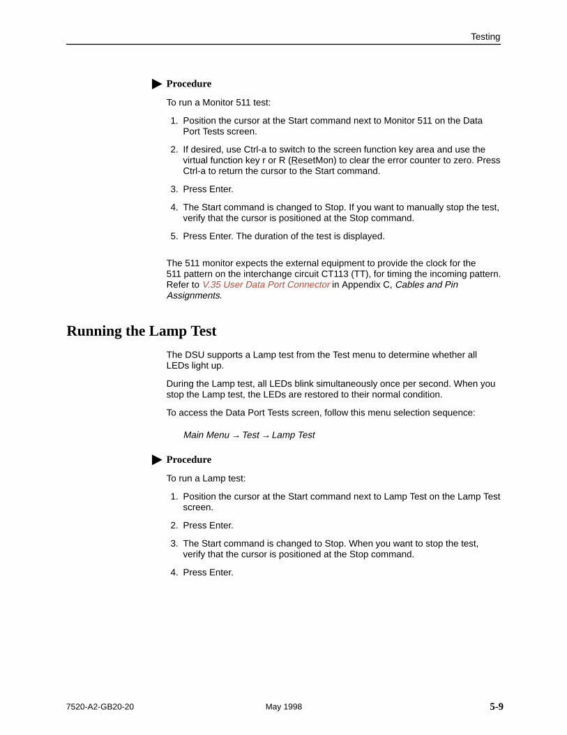
Running the Lamp Test
The DSU supports a Lamp test from the Test menu to determine whether allLEDs light up.
During the Lamp test, all LEDs blink simultaneously once per second. When youstop the Lamp test, the LEDs are restored to their normal condition.
To access the Data Port Tests screen, follow this menu selection sequence:
Main Menu →Test →Lamp Test
� Procedure
To run a Lamp test:
1. Position the cursor at the Start command next to Lamp Test on the Lamp Testscreen.
2. Press Enter.
3. The Start command is changed to Stop. When you want to stop the test,verify that the cursor is positioned at the Stop command.
4. Press Enter.
Testing
5-10 7520-A2-GB20-20May 1998
Ending an Active Test
A test initiated by the user can be ended by the user.
� A Test Timeout option is available to automatically terminate a user-initiatedLoopback or Pattern test after it has been running a specified period of time.Refer to Table A-1, System Options.
Test Timeout does not pertain to tests commanded by the:
— Network, such as the network-initiated CSU and DSU Loopbacks.
— DTE, such as the DTE-initiated Local Loopback.
� On each test screen is a command column. Pressing Enter when the cursoris on the Stop command stops the test.
� Use the Abort All Tests selection from the Test menu to stop all tests runningon all interfaces, with the exception of network or DTE-initiated loopbacks.Command Complete appears when all tests on all interfaces have beenterminated.
6-17520-A2-GB20-20 May 1998
Messages and Troubleshooting
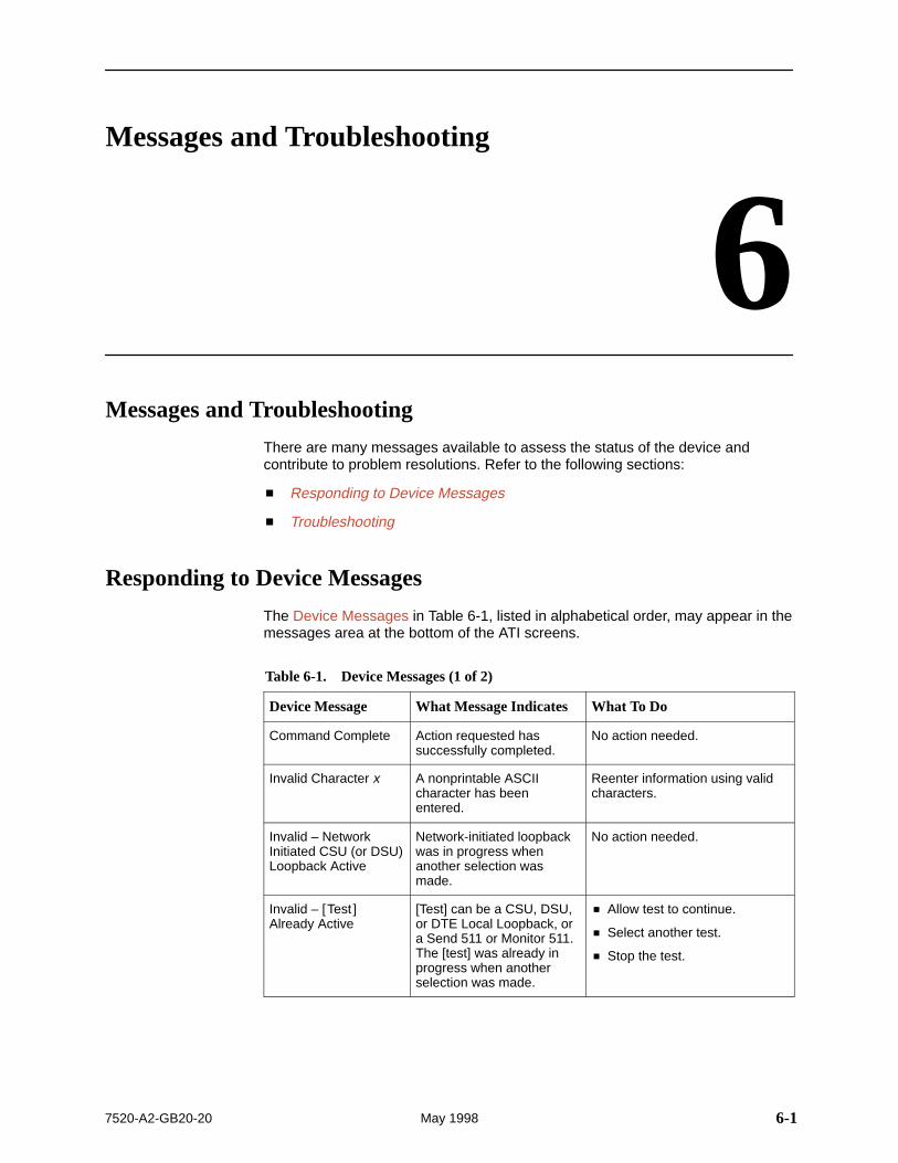
6Messages and Troubleshooting
There are many messages available to assess the status of the device andcontribute to problem resolutions. Refer to the following sections:
� Responding to Device Messages
� Troubleshooting
Responding to Device Messages
The Device Messages in Table 6-1, listed in alphabetical order, may appear in themessages area at the bottom of the ATI screens.
Table 6-1. Device Messages (1 of 2)
Device Message What Message Indicates What To Do
Command Complete Action requested hassuccessfully completed.
No action needed.
Invalid Character x A nonprintable ASCIIcharacter has beenentered.
Reenter information using validcharacters.
Invalid – NetworkInitiated CSU (or DSU)Loopback Active
Network-initiated loopbackwas in progress whenanother selection wasmade.
No action needed.
Invalid – [Test ]Already Active
[Test] can be a CSU, DSU,or DTE Local Loopback, ora Send 511 or Monitor 511.The [test] was already inprogress when anotherselection was made.
� Allow test to continue.
� Select another test.
� Stop the test.
Messages and Troubleshooting
6-2 7520-A2-GB20-20May 1998
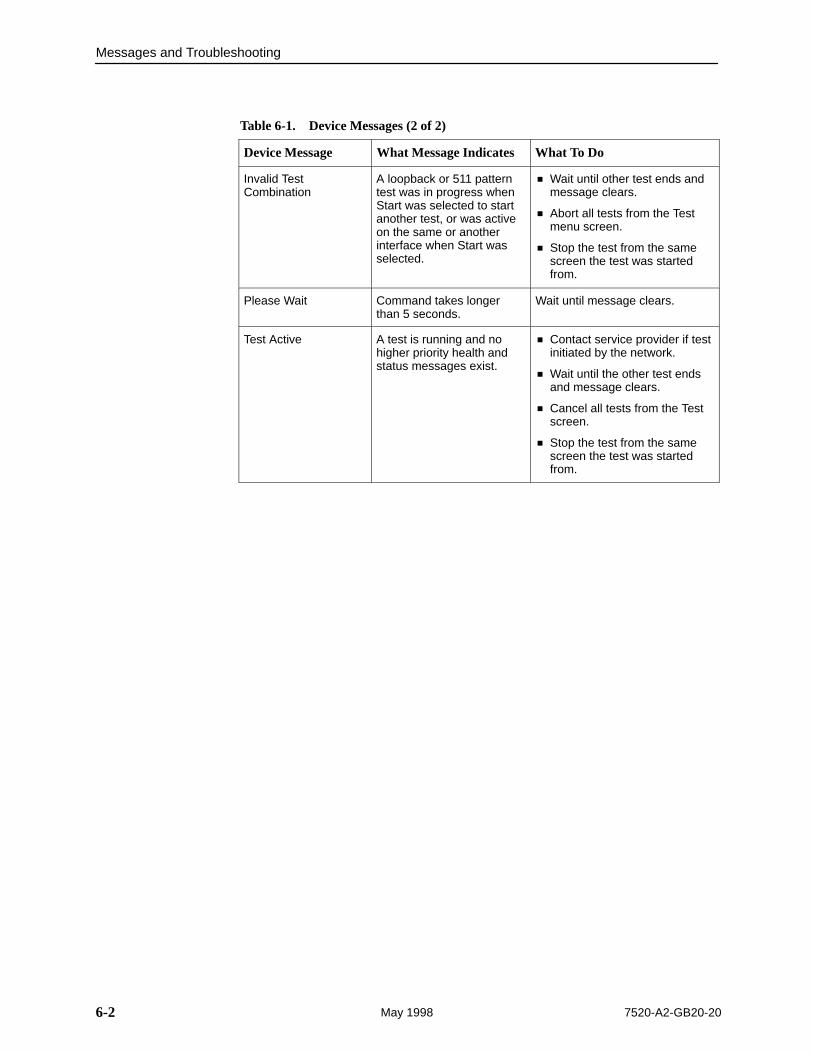
Table 6-1. Device Messages (2 of 2)
Device Message What To DoWhat Message Indicates
Invalid TestCombination
A loopback or 511 patterntest was in progress whenStart was selected to startanother test, or was activeon the same or anotherinterface when Start wasselected.
� Wait until other test ends andmessage clears.
� Abort all tests from the Testmenu screen.
� Stop the test from the samescreen the test was startedfrom.
Please Wait Command takes longerthan 5 seconds.
Wait until message clears.
Test Active A test is running and nohigher priority health andstatus messages exist.
� Contact service provider if testinitiated by the network.
� Wait until the other test endsand message clears.
� Cancel all tests from the Testscreen.
� Stop the test from the samescreen the test was startedfrom.
Messages and Troubleshooting
6-37520-A2-GB20-20 May 1998
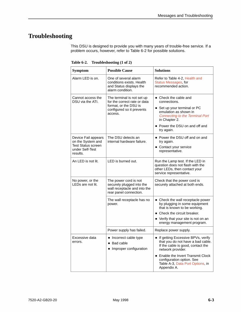
Troubleshooting
This DSU is designed to provide you with many years of trouble-free service. If aproblem occurs, however, refer to Table 6-2 for possible solutions.
Table 6-2. Troubleshooting (1 of 2)
Symptom Possible Cause Solutions
Alarm LED is on. One of several alarmconditions exists. Healthand Status displays thealarm condition.
Refer to Table 4-2, Health andStatus Messages, forrecommended action.
Cannot access theDSU via the ATI.
The terminal is not set upfor the correct rate or dataformat, or the DSU isconfigured so it preventsaccess.
� Check the cable andconnections.
� Set up your terminal or PCemulation as shown inConnecting to the Terminal Portin Chapter 2.
� Power the DSU on and off andtry again.
Device Fail appearson the System andTest Status screenunder Self-Testresults.
The DSU detects aninternal hardware failure.
� Power the DSU off and on andtry again.
� Contact your servicerepresentative.
An LED is not lit. LED is burned out. Run the Lamp test. If the LED inquestion does not flash with theother LEDs, then contact yourservice representative.
No power, or theLEDs are not lit.
The power cord is notsecurely plugged into thewall receptacle and into therear panel connection.
Check that the power cord issecurely attached at both ends.
The wall receptacle has nopower.
� Check the wall receptacle powerby plugging in some equipmentthat is known to be working.
� Check the circuit breaker.
� Verify that your site is not on anenergy management program.
Power supply has failed. Replace power supply.
Excessive dataerrors.
� Incorrect cable type
� Bad cable
� Improper configuration
� If getting Excessive BPVs, verifythat you do not have a bad cable.If the cable is good, contact thenetwork provider.p
� Enable the Invert Transmit Clockconfiguration option. See Table A-3, Data Port Options, inAppendix A.
Messages and Troubleshooting
6-4 7520-A2-GB20-20May 1998
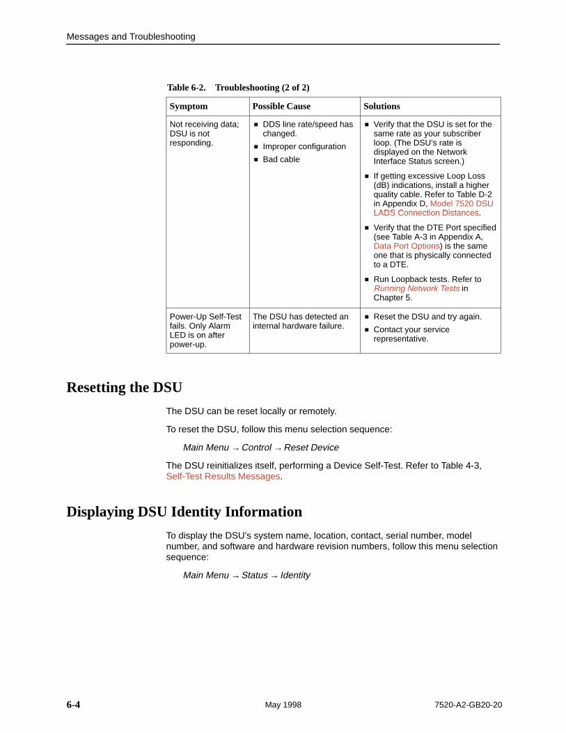
Table 6-2. Troubleshooting (2 of 2)
Symptom SolutionsPossible Cause
Not receiving data;DSU is notresponding.
� DDS line rate/speed haschanged.
� Improper configuration
� Bad cable
� Verify that the DSU is set for thesame rate as your subscriberloop. (The DSU’s rate isdisplayed on the NetworkInterface Status screen.)
� If getting excessive Loop Loss(dB) indications, install a higherquality cable. Refer to Table D-2in Appendix D, Model 7520 DSULADS Connection Distances
ppLADS Connection Distances.
� Verify that the DTE Port specified(see Table A-3 in Appendix A,Data Port Options) is the sameone that is physically connectedto a DTE.
� Run Loopback tests. Refer toRunning Network Tests inChapter 5.
Power-Up Self-Testfails. Only AlarmLED is on afterpower-up.
The DSU has detected aninternal hardware failure.
� Reset the DSU and try again.
� Contact your servicerepresentative.
Resetting the DSU
The DSU can be reset locally or remotely.
To reset the DSU, follow this menu selection sequence:
Main Menu →Control →Reset Device
The DSU reinitializes itself, performing a Device Self-Test. Refer to Table 4-3,Self-Test Results Messages.
Displaying DSU Identity Information
To display the DSU’s system name, location, contact, serial number, modelnumber, and software and hardware revision numbers, follow this menu selectionsequence:
Main Menu →Status → Identity
A-17520-A2-GB20-20 May 1998
Configuration Option Tables
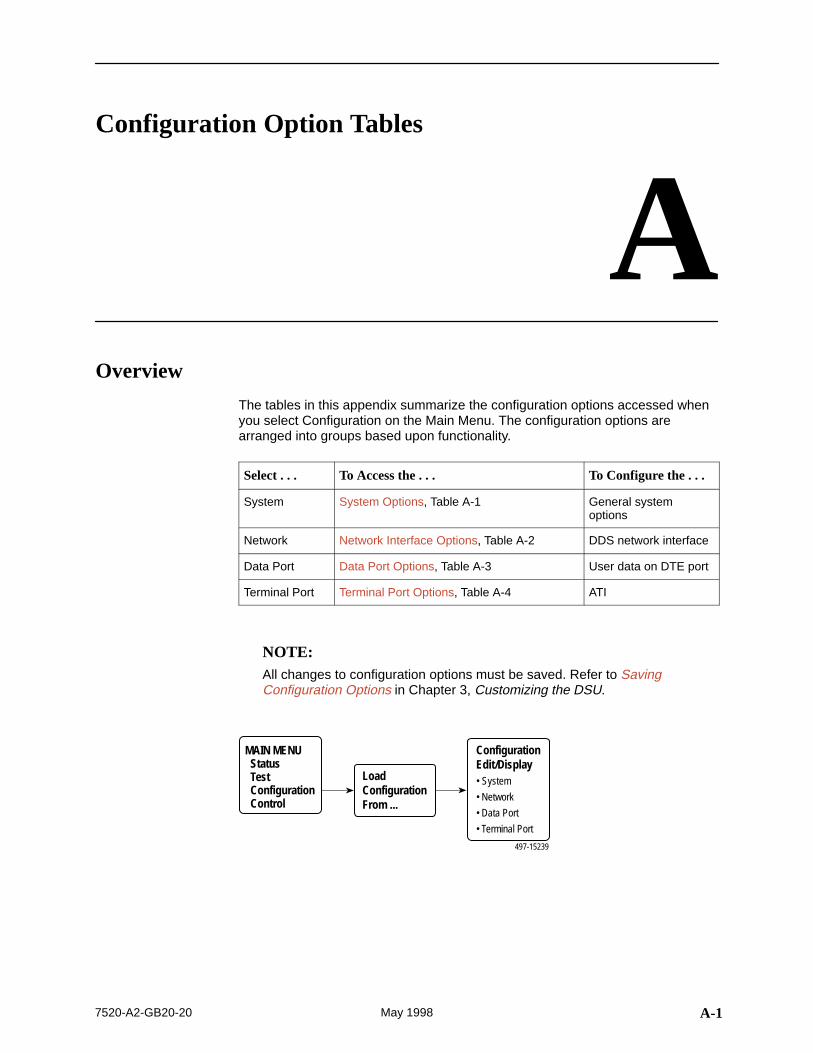
AOverview
The tables in this appendix summarize the configuration options accessed whenyou select Configuration on the Main Menu. The configuration options arearranged into groups based upon functionality.
Select . . . To Access the . . . To Configure the . . .
System System Options, Table A-1 General systemoptions
Network Network Interface Options, Table A-2 DDS network interface
Data Port Data Port Options, Table A-3 User data on DTE port
Terminal Port Terminal Port Options, Table A-4 ATI
NOTE:All changes to configuration options must be saved. Refer to SavingConfiguration Options in Chapter 3, Customizing the DSU.
ConfigurationEdit/Display• System
• Network
• Data Port
• Terminal Port
MAIN MENU Status Test Configuration Control
497-15239
LoadConfigurationFrom ...
Configuration Option Tables
A-2 7520-A2-GB20-20May 1998
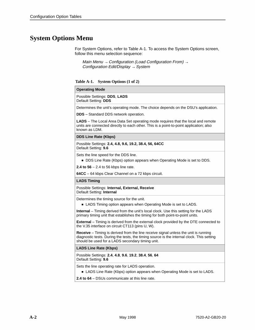
System Options Menu
For System Options, refer to Table A-1. To access the System Options screen,follow this menu selection sequence:
Main Menu →Configuration (Load Configuration From) →Configuration Edit/Display →System
Table A-1. System Options (1 of 2)
Operating Mode
Possible Settings: DDS, LADSDefault Setting: DDS
Determines the unit’s operating mode. The choice depends on the DSU’s application.
DDS – Standard DDS network operation.
LADS – The Local Area Data Set operating mode requires that the local and remoteunits are connected directly to each other. This is a point-to-point application; alsoknown as LDM.
DDS Line Rate (Kbps)
Possible Settings: 2.4, 4.8, 9.6, 19.2, 38.4, 56, 64CCDefault Setting: 9.6
Sets the line speed for the DDS line.� DDS Line Rate (Kbps) option appears when Operating Mode is set to DDS.
2.4 to 56 – 2.4 to 56 kbps line rate.
64CC – 64 kbps Clear Channel on a 72 kbps circuit.
LADS Timing
Possible Settings: Internal, External, ReceiveDefault Setting: Internal
Determines the timing source for the unit.� LADS Timing option appears when Operating Mode is set to LADS.
Internal – Timing derived from the unit’s local clock. Use this setting for the LADSprimary timing unit that establishes the timing for both point-to-point units.
External – Timing is derived from the external clock provided by the DTE connected tothe V.35 interface on circuit CT113 (pins U, W).
Receive – Timing is derived from the line receive signal unless the unit is runningdiagnostic tests. During the tests, the timing source is the internal clock. This settingshould be used for a LADS secondary timing unit.
LADS Line Rate (Kbps)
Possible Settings: 2.4, 4.8, 9.6, 19.2, 38.4, 56, 64Default Setting: 9.6
Sets the line operating rate for LADS operation.� LADS Line Rate (Kbps) option appears when Operating Mode is set to LADS.
2.4 to 64 – DSUs communicate at this line rate.
Configuration Option Tables
A-37520-A2-GB20-20 May 1998
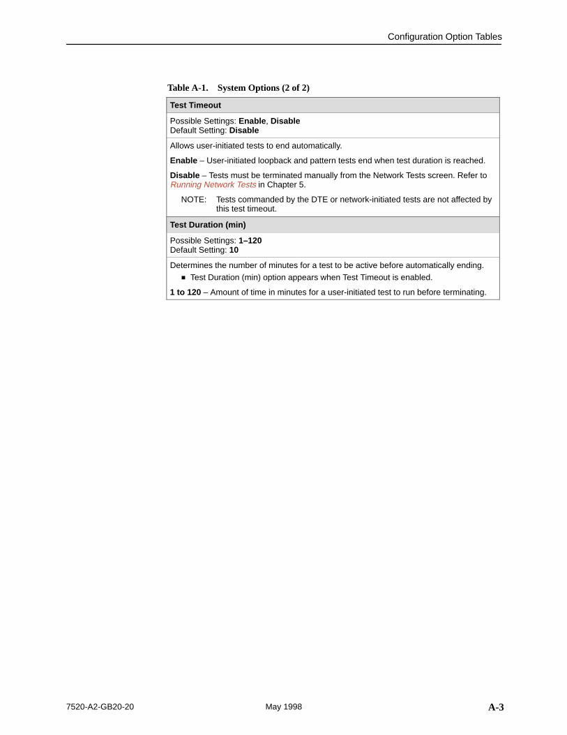
Table A-1. System Options (2 of 2)
Test Timeout
Possible Settings: Enable , DisableDefault Setting: Disable
Allows user-initiated tests to end automatically.
Enable – User-initiated loopback and pattern tests end when test duration is reached.
Disable – Tests must be terminated manually from the Network Tests screen. Refer toRunning Network Tests in Chapter 5.
NOTE: Tests commanded by the DTE or network-initiated tests are not affected bythis test timeout.
Test Duration (min)
Possible Settings: 1–120Default Setting: 10
Determines the number of minutes for a test to be active before automatically ending.� Test Duration (min) option appears when Test Timeout is enabled.
1 to 120 – Amount of time in minutes for a user-initiated test to run before terminating.
Configuration Option Tables
A-4 7520-A2-GB20-20May 1998
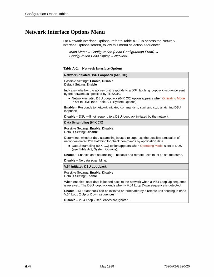
Network Interface Options Menu
For Network Interface Options, refer to Table A-2. To access the NetworkInterface Options screen, follow this menu selection sequence:
Main Menu →Configuration (Load Configuration From) →Configuration Edit/Display →Network
Table A-2. Network Interface Options
Network-initiated DSU Loopback (64K CC)
Possible Settings: Enable, DisableDefault Setting: Enable
Indicates whether the access unit responds to a DSU latching loopback sequence sentby the network as specified by TR62310.
� Network-initiated DSU Loopback (64K CC) option appears when Operating Modeis set to DDS (see Table A-1, System Options).
Enable – Responds to network-initiated commands to start and stop a latching DSUloopback.
Disable – DSU will not respond to a DSU loopback initiated by the network.
Data Scrambling (64K CC)
Possible Settings: Enable, DisableDefault Setting: Disable
Determines whether data scrambling is used to suppress the possible simulation ofnetwork-initiated DSU latching loopback commands by application data.
� Data Scrambling (64K CC) option appears when Operating Mode is set to DDS(see Table A-1, System Options).
Enable – Enables data scrambling. The local and remote units must be set the same.
Disable – No data scrambling.
V.54 Initiated DSU Loopback
Possible Settings: Enable, DisableDefault Setting: Enable
When enabled, user data is looped back to the network when a V.54 Loop Up sequenceis received. The DSU loopback ends when a V.54 Loop Down sequence is detected.
Enable – DSU loopback can be initiated or terminated by a remote unit sending in-bandV.54 Loop 2 Up or Down sequences.
Disable – V.54 Loop 2 sequences are ignored.
Configuration Option Tables
A-57520-A2-GB20-20 May 1998
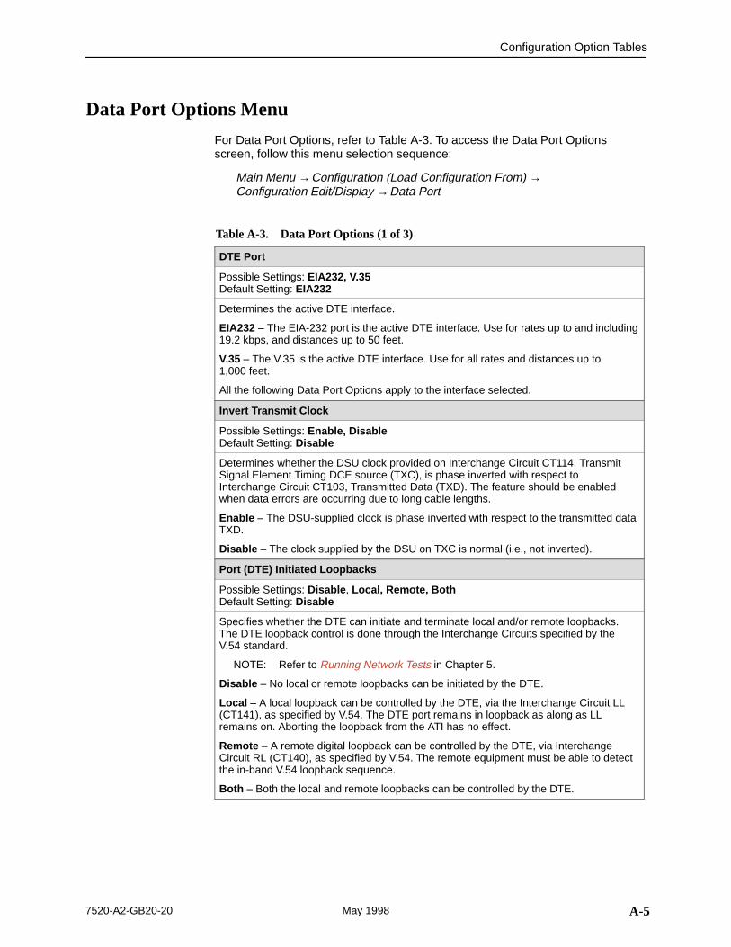
Data Port Options Menu
For Data Port Options, refer to Table A-3. To access the Data Port Optionsscreen, follow this menu selection sequence:
Main Menu →Configuration (Load Configuration From) →Configuration Edit/Display →Data Port
Table A-3. Data Port Options (1 of 3)
DTE Port
Possible Settings: EIA232, V.35Default Setting: EIA232
Determines the active DTE interface.
EIA232 – The EIA-232 port is the active DTE interface. Use for rates up to and including19.2 kbps, and distances up to 50 feet.
V.35 – The V.35 is the active DTE interface. Use for all rates and distances up to 1,000 feet.
All the following Data Port Options apply to the interface selected.
Invert Transmit Clock
Possible Settings: Enable, DisableDefault Setting: Disable
Determines whether the DSU clock provided on Interchange Circuit CT114, TransmitSignal Element Timing DCE source (TXC), is phase inverted with respect toInterchange Circuit CT103, Transmitted Data (TXD). The feature should be enabledwhen data errors are occurring due to long cable lengths.
Enable – The DSU-supplied clock is phase inverted with respect to the transmitted dataTXD.
Disable – The clock supplied by the DSU on TXC is normal (i.e., not inverted).
Port (DTE) Initiated Loopbacks
Possible Settings: Disable , Local, Remote, BothDefault Setting: Disable
Specifies whether the DTE can initiate and terminate local and/or remote loopbacks.The DTE loopback control is done through the Interchange Circuits specified by theV.54 standard.
NOTE: Refer to Running Network Tests in Chapter 5.
Disable – No local or remote loopbacks can be initiated by the DTE.
Local – A local loopback can be controlled by the DTE, via the Interchange Circuit LL(CT141), as specified by V.54. The DTE port remains in loopback as along as LLremains on. Aborting the loopback from the ATI has no effect.
Remote – A remote digital loopback can be controlled by the DTE, via InterchangeCircuit RL (CT140), as specified by V.54. The remote equipment must be able to detectthe in-band V.54 loopback sequence.
Both – Both the local and remote loopbacks can be controlled by the DTE.
Configuration Option Tables
A-6 7520-A2-GB20-20May 1998
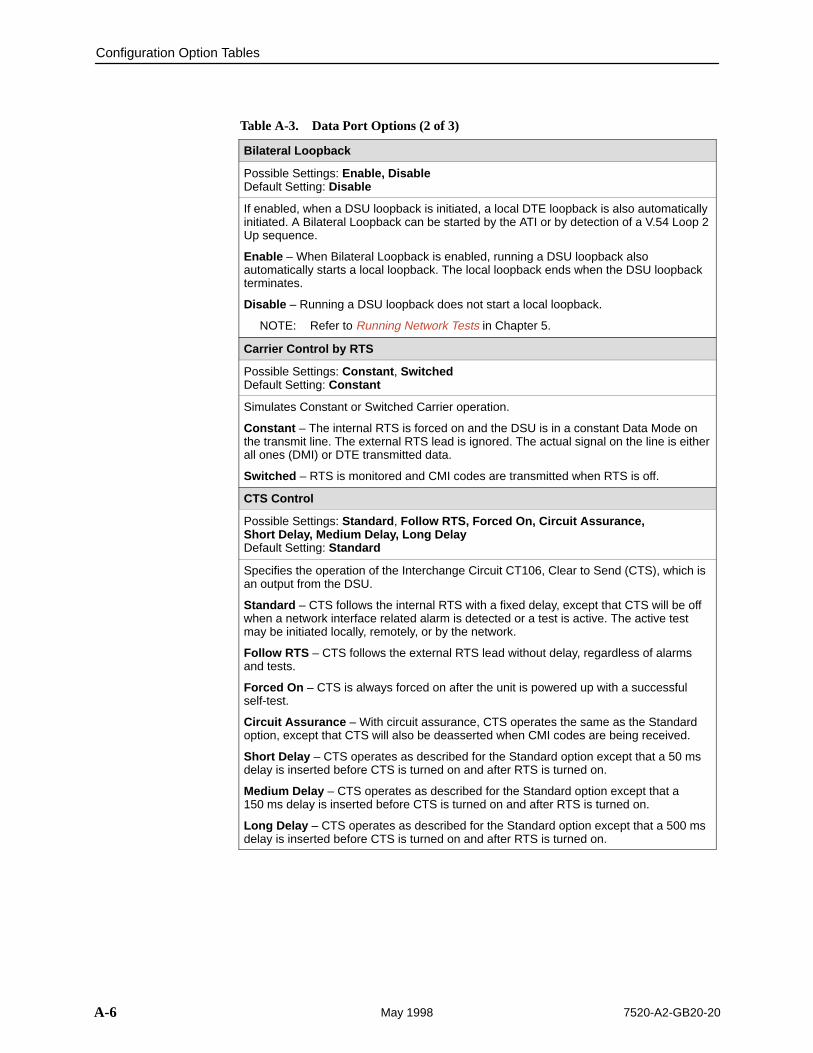
Table A-3. Data Port Options (2 of 3)
Bilateral Loopback
Possible Settings: Enable, DisableDefault Setting: Disable
If enabled, when a DSU loopback is initiated, a local DTE loopback is also automaticallyinitiated. A Bilateral Loopback can be started by the ATI or by detection of a V.54 Loop 2Up sequence.
Enable – When Bilateral Loopback is enabled, running a DSU loopback alsoautomatically starts a local loopback. The local loopback ends when the DSU loopbackterminates.
Disable – Running a DSU loopback does not start a local loopback.
NOTE: Refer to Running Network Tests in Chapter 5.
Carrier Control by RTS
Possible Settings: Constant , SwitchedDefault Setting: Constant
Simulates Constant or Switched Carrier operation.
Constant – The internal RTS is forced on and the DSU is in a constant Data Mode onthe transmit line. The external RTS lead is ignored. The actual signal on the line is eitherall ones (DMI) or DTE transmitted data.
Switched – RTS is monitored and CMI codes are transmitted when RTS is off.
CTS Control
Possible Settings: Standard , Follow RTS, Forced On, Circuit Assurance, Short Delay, Medium Delay, Long Delay Default Setting: Standard
Specifies the operation of the Interchange Circuit CT106, Clear to Send (CTS), which isan output from the DSU.
Standard – CTS follows the internal RTS with a fixed delay, except that CTS will be offwhen a network interface related alarm is detected or a test is active. The active testmay be initiated locally, remotely, or by the network.
Follow RTS – CTS follows the external RTS lead without delay, regardless of alarmsand tests.
Forced On – CTS is always forced on after the unit is powered up with a successfulself-test.
Circuit Assurance – With circuit assurance, CTS operates the same as the Standardoption, except that CTS will also be deasserted when CMI codes are being received.
Short Delay – CTS operates as described for the Standard option except that a 50 msdelay is inserted before CTS is turned on and after RTS is turned on.
Medium Delay – CTS operates as described for the Standard option except that a150 ms delay is inserted before CTS is turned on and after RTS is turned on.
Long Delay – CTS operates as described for the Standard option except that a 500 msdelay is inserted before CTS is turned on and after RTS is turned on.
Configuration Option Tables
A-77520-A2-GB20-20 May 1998
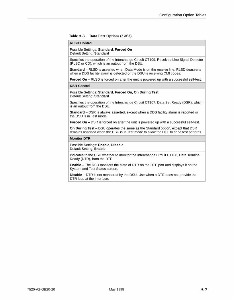
Table A-3. Data Port Options (3 of 3)
RLSD Control
Possible Settings: Standard , Forced OnDefault Setting: Standard
Specifies the operation of the Interchange Circuit CT109, Received Line Signal Detector(RLSD or CD), which is an output from the DSU.
Standard – RLSD is asserted when Data Mode is on the receive line. RLSD deassertswhen a DDS facility alarm is detected or the DSU is receiving CMI codes.
Forced On – RLSD is forced on after the unit is powered up with a successful self-test.
DSR Control
Possible Settings: Standard , Forced On, On During TestDefault Setting: Standard
Specifies the operation of the Interchange Circuit CT107, Data Set Ready (DSR), whichis an output from the DSU.
Standard – DSR is always asserted, except when a DDS facility alarm is reported orthe DSU is in Test mode.
Forced On – DSR is forced on after the unit is powered up with a successful self-test.
On During Test – DSU operates the same as the Standard option, except that DSRremains asserted when the DSU is in Test mode to allow the DTE to send test patterns.
Monitor DTR
Possible Settings: Enable , DisableDefault Setting: Enable
Indicates to the DSU whether to monitor the Interchange Circuit CT108, Data TerminalReady (DTR), from the DTE.
Enable – The DSU monitors the state of DTR on the DTE port and displays it on theSystem and Test Status screen.
Disable – DTR is not monitored by the DSU. Use when a DTE does not provide theDTR lead at the interface.
Configuration Option Tables
A-8 7520-A2-GB20-20May 1998
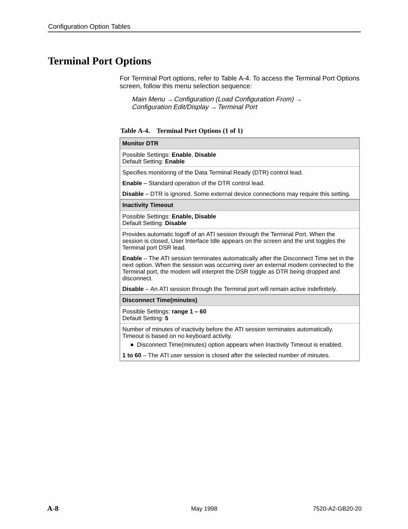
Terminal Port Options
For Terminal Port options, refer to Table A-4. To access the Terminal Port Optionsscreen, follow this menu selection sequence:
Main Menu →Configuration (Load Configuration From) →Configuration Edit/Display →Terminal Port
Table A-4. Terminal Port Options (1 of 1)
Monitor DTR
Possible Settings: Enable , DisableDefault Setting: Enable
Specifies monitoring of the Data Terminal Ready (DTR) control lead.
Enable – Standard operation of the DTR control lead.
Disable – DTR is ignored. Some external device connections may require this setting.
Inactivity Timeout
Possible Settings: Enable, DisableDefault Setting: Disable
Provides automatic logoff of an ATI session through the Terminal Port. When thesession is closed, User Interface Idle appears on the screen and the unit toggles theTerminal port DSR lead.
Enable – The ATI session terminates automatically after the Disconnect Time set in thenext option. When the session was occurring over an external modem connected to theTerminal port, the modem will interpret the DSR toggle as DTR being dropped anddisconnect.
Disable – An ATI session through the Terminal port will remain active indefinitely.
Disconnect Time(minutes)
Possible Settings: range 1 – 60 Default Setting: 5
Number of minutes of inactivity before the ATI session terminates automatically.Timeout is based on no keyboard activity.
� Disconnect Time(minutes) option appears when Inactivity Timeout is enabled.
1 to 60 – The ATI user session is closed after the selected number of minutes.
B-17520-A2-GB20-20 May 1998
Worksheets
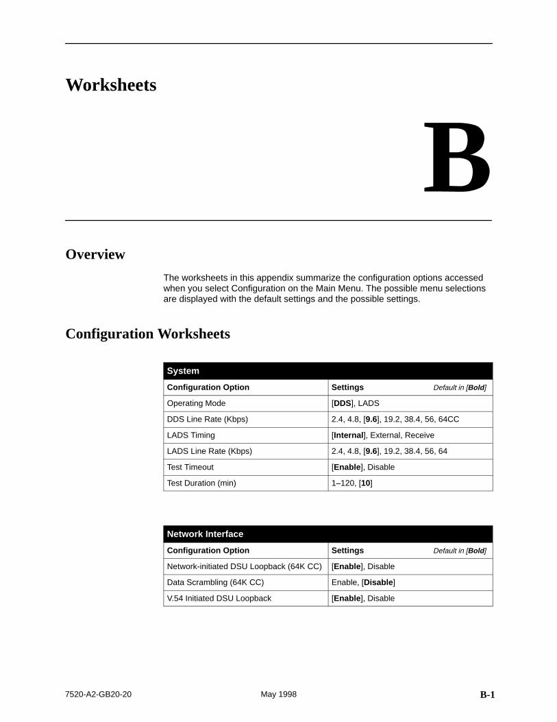
BOverview
The worksheets in this appendix summarize the configuration options accessedwhen you select Configuration on the Main Menu. The possible menu selectionsare displayed with the default settings and the possible settings.
Configuration Worksheets
System
Configuration Option Settings Default in [Bold ]
Operating Mode [DDS], LADS
DDS Line Rate (Kbps) 2.4, 4.8, [9.6], 19.2, 38.4, 56, 64CC
LADS Timing [Internal ], External, Receive
LADS Line Rate (Kbps) 2.4, 4.8, [9.6], 19.2, 38.4, 56, 64
Test Timeout [Enable ], Disable
Test Duration (min) 1–120, [10]
Network Interface
Configuration Option Settings Default in [Bold ]
Network-initiated DSU Loopback (64K CC) [Enable ], Disable
Data Scrambling (64K CC) Enable, [Disable ]
V.54 Initiated DSU Loopback [Enable ], Disable
Worksheets
B-2 7520-A2-GB20-20May 1998
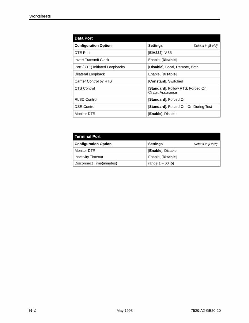
Data Port
Configuration Option Settings Default in [Bold ]
DTE Port [EIA232], V.35
Invert Transmit Clock Enable, [Disable ]
Port (DTE) Initiated Loopbacks [Disable ], Local, Remote, Both
Bilateral Loopback Enable, [Disable ]
Carrier Control by RTS [Constant ], Switched
CTS Control [Standard ], Follow RTS, Forced On,Circuit Assurance
RLSD Control [Standard ], Forced On
DSR Control [Standard ], Forced On, On During Test
Monitor DTR [Enable ], Disable
Terminal Port
Configuration Option Settings Default in [Bold ]
Monitor DTR [Enable ], Disable
Inactivity Timeout Enable, [Disable ]
Disconnect Time(minutes) range 1 – 60 [5]
C-17520-A2-GB20-20 May 1998
Cables and Pin Assignments
COverview
The following sections provide pin assignments for the:
� Terminal Port EIA-232 Connector
� EIA-232 User Data Port Connector
� V.35 User Data Port Connector
� Standard EIA-232D Crossover Cable
� Modular RJ48S DDS Network Interface Cable
Cables and Pin Assignments
C-2 7520-A2-GB20-20May 1998
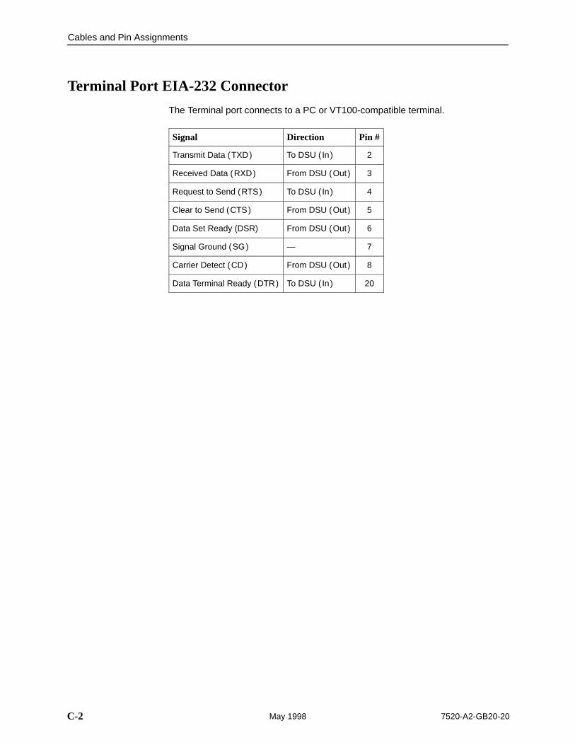
Terminal Port EIA-232 Connector
The Terminal port connects to a PC or VT100-compatible terminal.
Signal Direction Pin #
Transmit Data (TXD) To DSU ( In) 2
Received Data (RXD) From DSU (Out ) 3
Request to Send (RTS) To DSU ( In) 4
Clear to Send (CTS) From DSU (Out ) 5
Data Set Ready (DSR) From DSU (Out ) 6
Signal Ground (SG) — 7
Carrier Detect (CD) From DSU (Out ) 8
Data Terminal Ready (DTR) To DSU ( In) 20
Cables and Pin Assignments
C-37520-A2-GB20-20 May 1998
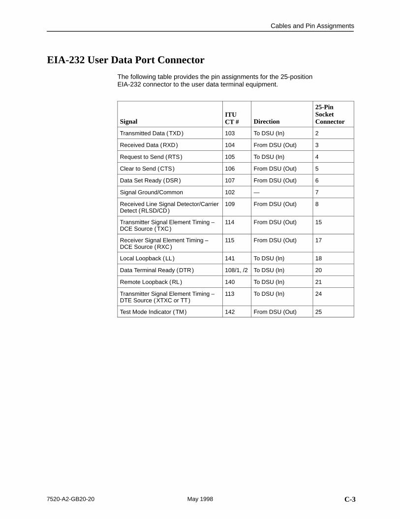
EIA-232 User Data Port Connector
The following table provides the pin assignments for the 25-position EIA-232 connector to the user data terminal equipment.
SignalITU CT # Direction
25-PinSocketConnector
Transmitted Data (TXD) 103 To DSU (In) 2
Received Data (RXD) 104 From DSU (Out) 3
Request to Send (RTS) 105 To DSU (In) 4
Clear to Send (CTS) 106 From DSU (Out) 5
Data Set Ready (DSR) 107 From DSU (Out) 6
Signal Ground/Common 102 — 7
Received Line Signal Detector/CarrierDetect (RLSD/CD)
109 From DSU (Out) 8
Transmitter Signal Element Timing –DCE Source (TXC)
114 From DSU (Out) 15
Receiver Signal Element Timing –DCE Source (RXC)
115 From DSU (Out) 17
Local Loopback (LL) 141 To DSU (In) 18
Data Terminal Ready (DTR) 108/1, /2 To DSU (In) 20
Remote Loopback (RL) 140 To DSU (In) 21
Transmitter Signal Element Timing –DTE Source (XTXC or TT)
113 To DSU (In) 24
Test Mode Indicator (TM) 142 From DSU (Out) 25
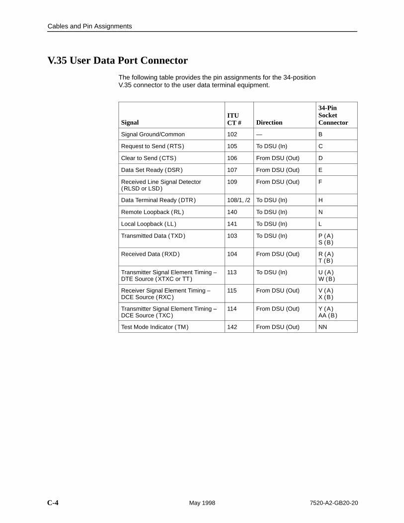
Cables and Pin Assignments
C-4 7520-A2-GB20-20May 1998
V.35 User Data Port Connector
The following table provides the pin assignments for the 34-position V.35 connector to the user data terminal equipment.
SignalITU CT # Direction
34-PinSocketConnector
Signal Ground/Common 102 — B
Request to Send (RTS) 105 To DSU (In) C
Clear to Send (CTS) 106 From DSU (Out) D
Data Set Ready (DSR) 107 From DSU (Out) E
Received Line Signal Detector(RLSD or LSD)
109 From DSU (Out) F
Data Terminal Ready (DTR) 108/1, /2 To DSU (In) H
Remote Loopback (RL) 140 To DSU (In) N
Local Loopback (LL) 141 To DSU (In) L
Transmitted Data (TXD) 103 To DSU (In) P (A)S (B)
Received Data (RXD) 104 From DSU (Out) R (A)T (B)
Transmitter Signal Element Timing –DTE Source (XTXC or TT)
113 To DSU (In) U (A)W (B)
Receiver Signal Element Timing –DCE Source (RXC)
115 From DSU (Out) V (A)X (B)
Transmitter Signal Element Timing –DCE Source (TXC)
114 From DSU (Out) Y (A)AA (B)
Test Mode Indicator (TM) 142 From DSU (Out) NN
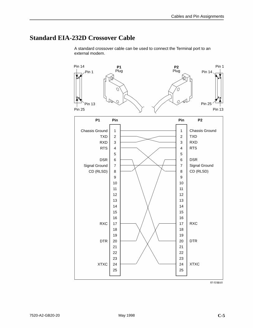
Cables and Pin Assignments
C-57520-A2-GB20-20 May 1998
Standard EIA-232D Crossover Cable
A standard crossover cable can be used to connect the Terminal port to anexternal modem.
Pin 1
Pin 14
Pin 13
Pin 25
Pin 1
Pin 14
Pin 13
Pin 25
P2Plug
Chassis Ground
TXD
RXD
RTS
DSR
Signal Ground
CD (RLSD)
RXC
DTR
XTXC
1
2
3
4
5
6
7
8
9
10
11
12
13
14
15
16
17
18
19
20
21
22
23
24
25
Pin
97-15180-01
1
2
3
4
5
6
7
8
9
10
11
12
13
14
15
16
17
18
19
20
21
22
23
24
25
P1
Chassis Ground
TXD
RXD
RTS
DSR
Signal Ground
CD (RLSD)
RXC
DTR
XTXC
Pin P2
P1Plug
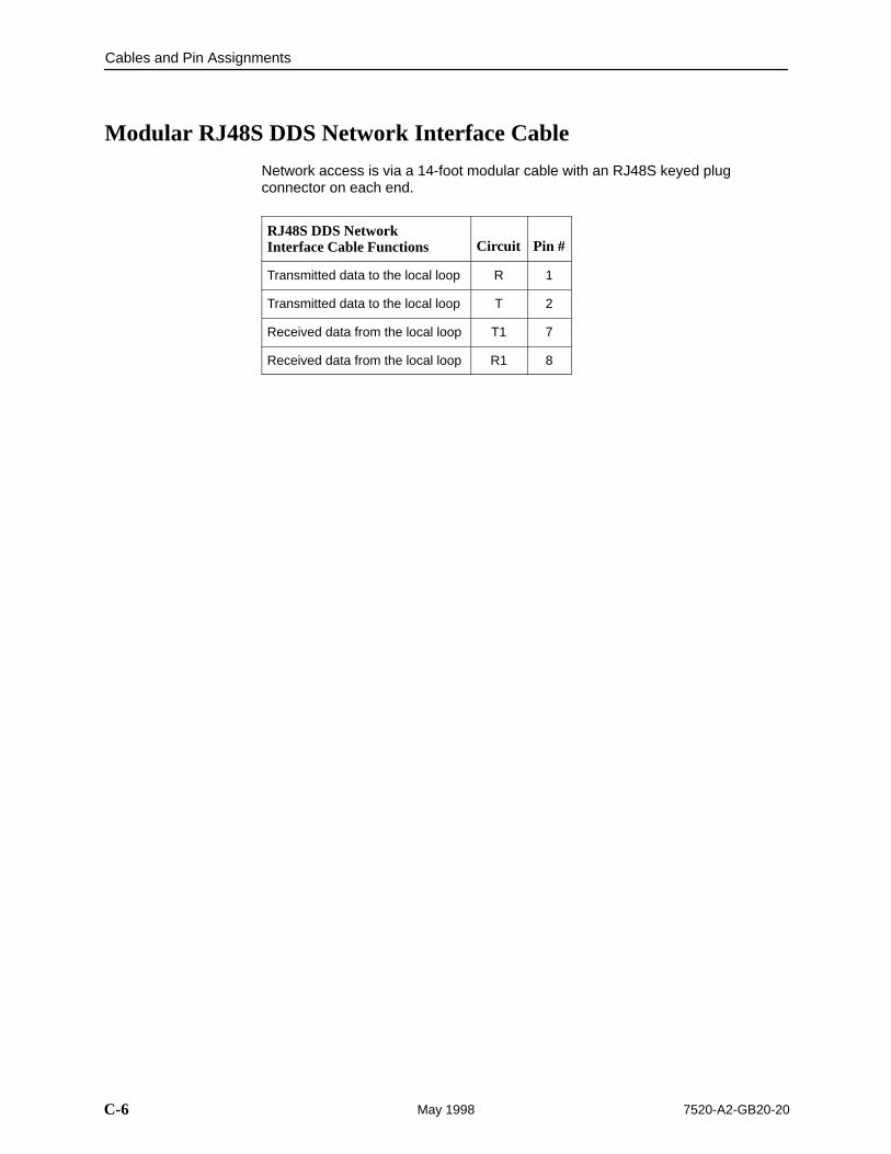
Cables and Pin Assignments
C-6 7520-A2-GB20-20May 1998
Modular RJ48S DDS Network Interface Cable
Network access is via a 14-foot modular cable with an RJ48S keyed plugconnector on each end.
RJ48S DDS Network Interface Cable Functions Circuit Pin #
Transmitted data to the local loop R 1
Transmitted data to the local loop T 2
Received data from the local loop T1 7
Received data from the local loop R1 8
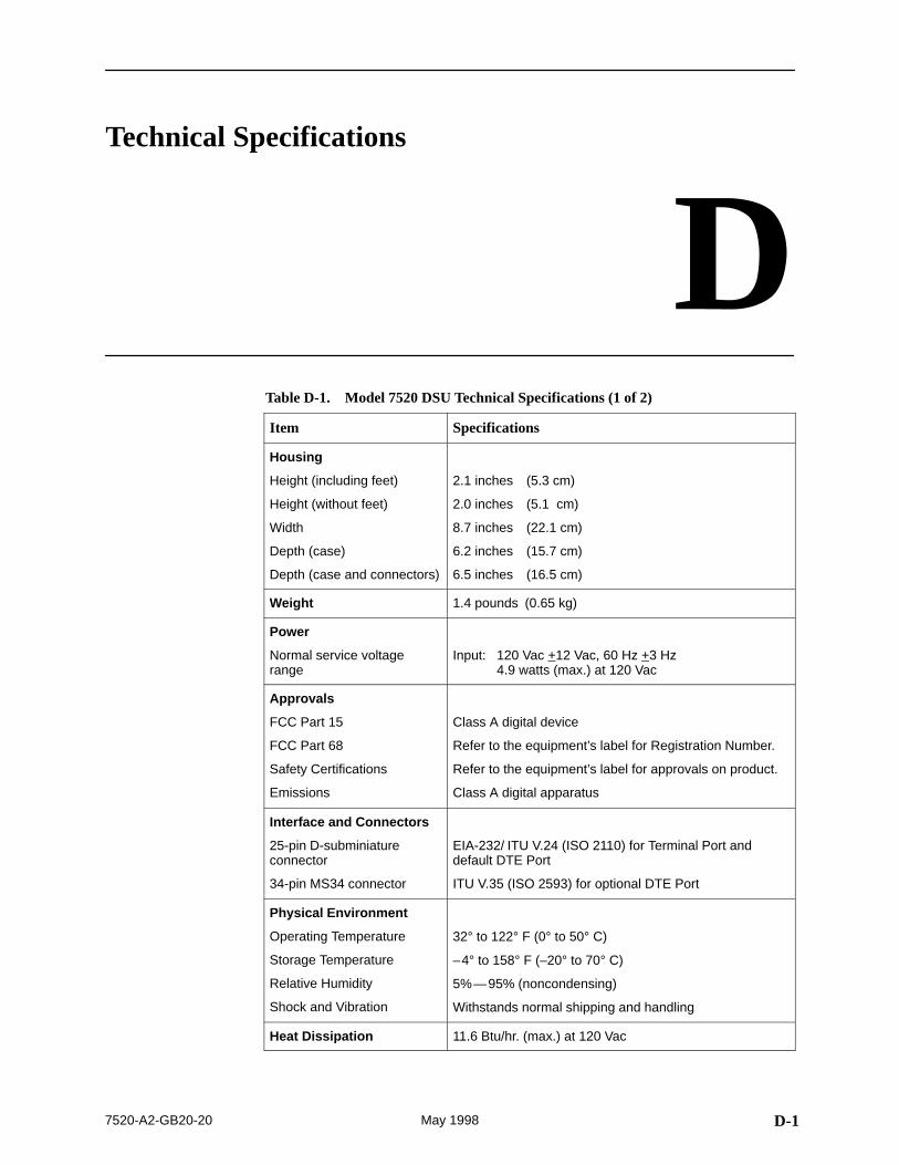
D-17520-A2-GB20-20 May 1998
Technical Specifications
DTable D-1. Model 7520 DSU Technical Specifications (1 of 2)
Item Specifications
Housing
Height (including feet)
Height (without feet)
Width
Depth (case)
Depth (case and connectors)
2.1 inches (5.3 cm)
2.0 inches (5.1 cm)
8.7 inches (22.1 cm)
6.2 inches (15.7 cm)
6.5 inches (16.5 cm)
Weight 1.4 pounds (0.65 kg)
Power
Normal service voltagerange
Input: 120 Vac +12 Vac, 60 Hz +3 Hz4.9 watts (max.) at 120 Vac
Approvals
FCC Part 15
FCC Part 68
Safety Certifications
Emissions
Class A digital device
Refer to the equipment’s label for Registration Number.
Refer to the equipment’s label for approvals on product.
Class A digital apparatus
Interface and Connectors
25-pin D-subminiatureconnector
34-pin MS34 connector
EIA-232/ ITU V.24 (ISO 2110) for Terminal Port anddefault DTE Port
ITU V.35 (ISO 2593) for optional DTE Port
Physical Environment
Operating Temperature
Storage Temperature
Relative Humidity
Shock and Vibration
32° to 122° F (0° to 50° C)
–4° to 158° F (–20° to 70° C)
5%—95% (noncondensing)
Withstands normal shipping and handling
Heat Dissipation 11.6 Btu/hr. (max.) at 120 Vac
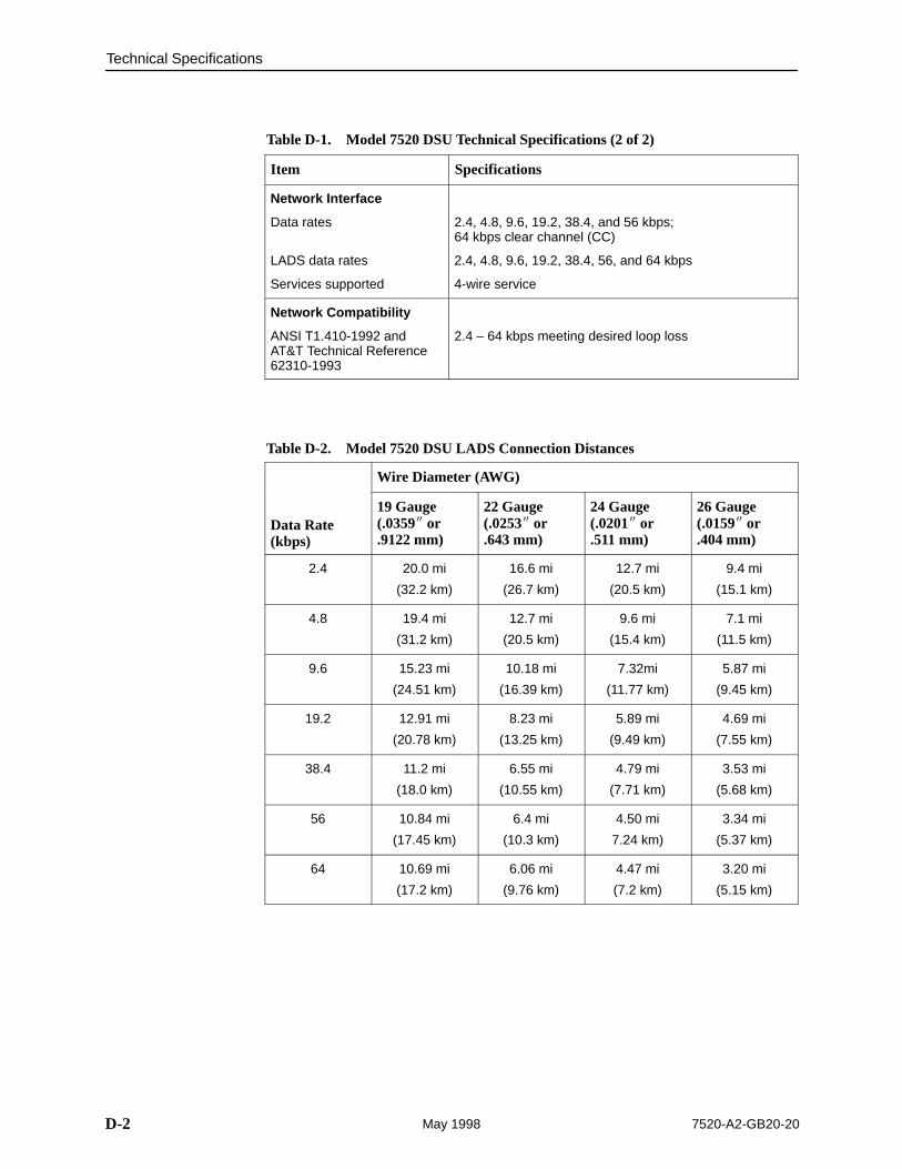
Technical Specifications
D-2 7520-A2-GB20-20May 1998
Table D-1. Model 7520 DSU Technical Specifications (2 of 2)
Item Specifications
Network Interface
Data rates
LADS data rates
Services supported
2.4, 4.8, 9.6, 19.2, 38.4, and 56 kbps; 64 kbps clear channel (CC)
2.4, 4.8, 9.6, 19.2, 38.4, 56, and 64 kbps
4-wire service
Network Compatibility
ANSI T1.410-1992 and AT&T Technical Reference62310-1993
2.4 – 64 kbps meeting desired loop loss
Table D-2. Model 7520 DSU LADS Connection Distances
Wire Diameter (AWG)
Data Rate(kbps)
19 Gauge(.0359� or.9122 mm)
22 Gauge(.0253� or.643 mm)
24 Gauge(.0201� or.511 mm)
26 Gauge(.0159� or.404 mm)
2.4 20.0 mi
(32.2 km)
16.6 mi
(26.7 km)
12.7 mi
(20.5 km)
9.4 mi
(15.1 km)
4.8 19.4 mi
(31.2 km)
12.7 mi
(20.5 km)
9.6 mi
(15.4 km)
7.1 mi
(11.5 km)
9.6 15.23 mi
(24.51 km)
10.18 mi
(16.39 km)
7.32mi
(11.77 km)
5.87 mi
(9.45 km)
19.2 12.91 mi
(20.78 km)
8.23 mi
(13.25 km)
5.89 mi
(9.49 km)
4.69 mi
(7.55 km)
38.4 11.2 mi
(18.0 km)
6.55 mi
(10.55 km)
4.79 mi
(7.71 km)
3.53 mi
(5.68 km)
56 10.84 mi
(17.45 km)
6.4 mi
(10.3 km)
4.50 mi
7.24 km)
3.34 mi
(5.37 km)
64 10.69 mi
(17.2 km)
6.06 mi
(9.76 km)
4.47 mi
(7.2 km)
3.20 mi
(5.15 km)
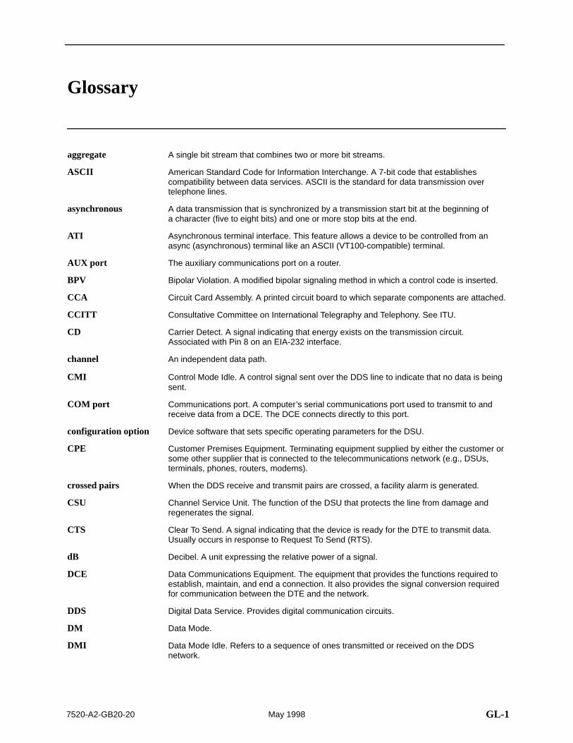
GL-17520-A2-GB20-20 May 1998
Glossary
A single bit stream that combines two or more bit streams.
American Standard Code for Information Interchange. A 7-bit code that establishescompatibility between data services. ASCII is the standard for data transmission overtelephone lines.
A data transmission that is synchronized by a transmission start bit at the beginning ofa character (five to eight bits) and one or more stop bits at the end.
Asynchronous terminal interface. This feature allows a device to be controlled from anasync (asynchronous) terminal like an ASCII (VT100-compatible) terminal.
The auxiliary communications port on a router.
Bipolar Violation. A modified bipolar signaling method in which a control code is inserted.
Circuit Card Assembly. A printed circuit board to which separate components are attached.
Consultative Committee on International Telegraphy and Telephony. See ITU.
Carrier Detect. A signal indicating that energy exists on the transmission circuit.Associated with Pin 8 on an EIA-232 interface.
An independent data path.
Control Mode Idle. A control signal sent over the DDS line to indicate that no data is beingsent.
Communications port. A computer’s serial communications port used to transmit to andreceive data from a DCE. The DCE connects directly to this port.
Device software that sets specific operating parameters for the DSU.
Customer Premises Equipment. Terminating equipment supplied by either the customer orsome other supplier that is connected to the telecommunications network (e.g., DSUs,terminals, phones, routers, modems).
When the DDS receive and transmit pairs are crossed, a facility alarm is generated.
Channel Service Unit. The function of the DSU that protects the line from damage andregenerates the signal.
Clear To Send. A signal indicating that the device is ready for the DTE to transmit data.Usually occurs in response to Request To Send (RTS).
Decibel. A unit expressing the relative power of a signal.
Data Communications Equipment. The equipment that provides the functions required toestablish, maintain, and end a connection. It also provides the signal conversion requiredfor communication between the DTE and the network.
Digital Data Service. Provides digital communication circuits.
Data Mode.
Data Mode Idle. Refers to a sequence of ones transmitted or received on the DDSnetwork.
aggregate
ASCII
asynchronous
ATI
AUX port
BPV
CCA
CCITT
CD
channel
CMI
COM port
configuration option
CPE
crossed pairs
CSU
CTS
dB
DCE
DDS
DM
DMI
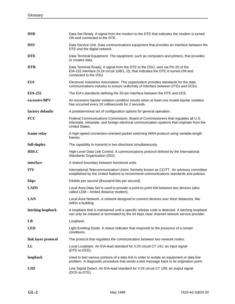
Glossary
GL-2 7520-A2-GB20-20May 1998
Data Set Ready. A signal from the modem to the DTE that indicates the modem is turnedON and connected to the DTE.
Data Service Unit. Data communications equipment that provides an interface between theDTE and the digital network.
Data Terminal Equipment. The equipment, such as computers and printers, that providesor creates data.
Data Terminal Ready. A signal from the DTE to the DSU, sent via Pin 20 of theEIA-232 interface (V.24 circuit 108/1, /2), that indicates the DTE is turned ON andconnected to the DSU.
Electronic Industries Association. This organization provides standards for the datacommunications industry to ensure uniformity of interface between DTEs and DCEs.
The EIA’s standards defining the 25-pin interface between the DTE and DCE.
An excessive bipolar violation condition results when at least one invalid bipolar violationhas occurred every 20 milliseconds for 2 seconds.
A predetermined set of configuration options for general operation.
Federal Communications Commission. Board of Commissioners that regulates all U.S.interstate, intrastate, and foreign electrical communication systems that originate from theUnited States.
A high-speed connection-oriented packet switching WAN protocol using variable-lengthframes.
The capability to transmit in two directions simultaneously.
High-Level Data Link Control. A communications protocol defined by the InternationalStandards Organization (ISO).
A shared boundary between functional units.
International Telecommunication Union, formerly known as CCITT. An advisory committeeestablished by the United Nations to recommend communications standards and policies.
Kilobits per second (thousand bits per second).
Local Area Data Set is used to provide a point-to-point link between two devices (alsocalled LDM – limited distance modem).
Local Area Network. A network designed to connect devices over short distances, likewithin a building.
A loopback that is maintained until a specific release code is detected. A latching loopbackcan only be initiated or terminated by the 64 kbps clear channel network service provider.
Loopback.
Light Emitting Diode. A status indicator that responds to the presence of a certainconditions.
The protocol that regulates the communication between two network nodes.
Local Loopback. An EIA-lead standard for V.24 circuit CT 141; an input signal(DTE-to-DCE).
Used to test various portions of a data link in order to isolate an equipment or data lineproblem. A diagnostic procedure that sends a test message back to its origination point.
Line Signal Detect. An EIA-lead standard for V.24 circuit CT 109; an output signal(DCE-to-DTE).
DSR
DSU
DTE
DTR
EIA
EIA-232
excessive BPV
factory defaults
FCC
frame relay
full-duplex
HDLC
interface
ITU
kbps
LADS
LAN
latching loopback
LB
LED
link layer protocol
LL
loopback
LSD
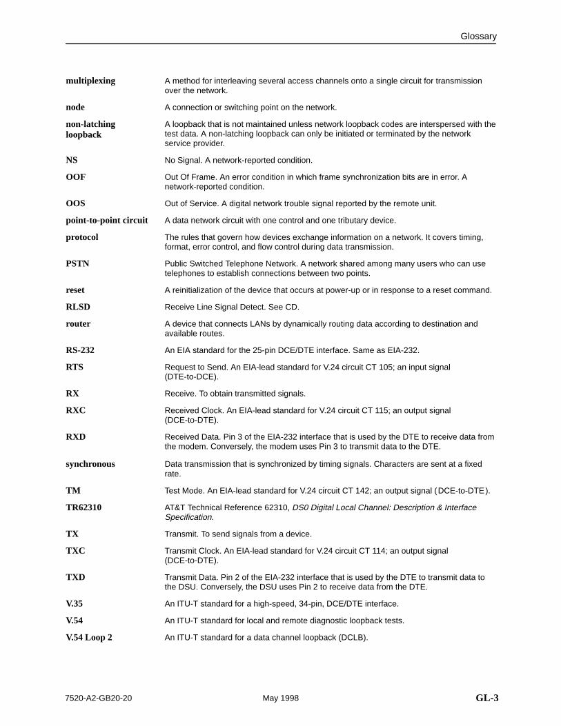
Glossary
GL-37520-A2-GB20-20 May 1998
A method for interleaving several access channels onto a single circuit for transmissionover the network.
A connection or switching point on the network.
A loopback that is not maintained unless network loopback codes are interspersed with thetest data. A non-latching loopback can only be initiated or terminated by the networkservice provider.
No Signal. A network-reported condition.
Out Of Frame. An error condition in which frame synchronization bits are in error. Anetwork-reported condition.
Out of Service. A digital network trouble signal reported by the remote unit.
A data network circuit with one control and one tributary device.
The rules that govern how devices exchange information on a network. It covers timing,format, error control, and flow control during data transmission.
Public Switched Telephone Network. A network shared among many users who can usetelephones to establish connections between two points.
A reinitialization of the device that occurs at power-up or in response to a reset command.
Receive Line Signal Detect. See CD.
A device that connects LANs by dynamically routing data according to destination andavailable routes.
An EIA standard for the 25-pin DCE/DTE interface. Same as EIA-232.
Request to Send. An EIA-lead standard for V.24 circuit CT 105; an input signal(DTE-to-DCE).
Receive. To obtain transmitted signals.
Received Clock. An EIA-lead standard for V.24 circuit CT 115; an output signal(DCE-to-DTE).
Received Data. Pin 3 of the EIA-232 interface that is used by the DTE to receive data fromthe modem. Conversely, the modem uses Pin 3 to transmit data to the DTE.
Data transmission that is synchronized by timing signals. Characters are sent at a fixedrate.
Test Mode. An EIA-lead standard for V.24 circuit CT 142; an output signal (DCE-to-DTE).
AT&T Technical Reference 62310, DS0 Digital Local Channel: Description & InterfaceSpecification.
Transmit. To send signals from a device.
Transmit Clock. An EIA-lead standard for V.24 circuit CT 114; an output signal(DCE-to-DTE).
Transmit Data. Pin 2 of the EIA-232 interface that is used by the DTE to transmit data tothe DSU. Conversely, the DSU uses Pin 2 to receive data from the DTE.
An ITU-T standard for a high-speed, 34-pin, DCE/DTE interface.
An ITU-T standard for local and remote diagnostic loopback tests.
An ITU-T standard for a data channel loopback (DCLB).
multiplexing
node
non-latchingloopback
NS
OOF
OOS
point-to-point circuit
protocol
PSTN
reset
RLSD
router
RS-232
RTS
RX
RXC
RXD
synchronous
TM
TR62310
TX
TXC
TXD
V.35
V.54
V.54 Loop 2
Glossary
GL-4 7520-A2-GB20-20May 1998
Wide Area Network. A network that operates over long distances and spans a relativelylarge geographic area (e.g., a country).
A random bit test 511 bytes in length.
WAN
511
IN-17520-A2-GB20-20 May 1998
Index
Numbers511 test pattern, 5-6– 5-7
Aalarm
condition, 4-1LED, 4-9
ASCII, printable characters, 3-1ATI
Configuration menu, 3-3Control menu, 3-1, 6-4exiting, 2-8initiating, 2-2menus, 2-2monitoring, 4-1Status menu, 4-2, 4-6, 4-7, 4-8Terminal Port options, A-8Test menu, 5-1, 5-3, 5-7, 5-9timeout, A-8
BBilateral Loopback, A-6
Ccables
DDS network, C-6EIA-232 crossover, C-5rear panel, C-1
Carrier Control by RTS, Data Port option, A-6CD (Carrier Detect), RLSD Control option, A-6clocking, Data Port option, A-5communication protocol options, A-2configuration
example, 1-2option areas, 3-3option tables, A-1option worksheets, B-1saving, 3-2
Configuration menu, 3-3
connectorsEIA-232 DTE, C-3rear panel, C-1V.35 DTE, C-4
Control menu, 3-1, 6-4crossover EIA-232 cable, C-5CTS
clear to send LED, 4-11Control option, A-6
customer, configuration areas, 3-3
Ddata port
options, A-5tests, 5-7
Data Port Options, A-5Data Scrambling, Network Interface option, A-4DDS, Operating Mode setting, A-2DDS Line Rate, System option, A-2defaults, configuration option, 3-3detecting problems, 4-1device
messages, 6-1– 6-2name, 3-1reset, 6-4
Disconnect Time, Terminal Port option, A-8displaying
configuration options, 3-3default configuration, 3-3identity information, 2-2revision numbers, 6-4serial number, 6-4
DM, data mode LED, 4-10DSR, Control option, A-7DSU Loopback
network-initiated, A-4V.54-initiated, A-4
DTE connector, EIA-232 pinouts, C-3DTE Port, Data Port option, A-5DTE test, 5-7DTE-initiated loopbacks, Data Port option, A-5DTR
data terminal ready LED, 4-11Monitor option for DTE, A-7Monitor option for Terminal, A-8
Index
IN-2 7520-A2-GB20-20May 1998
Eeffective access, to ATI, 2-3EIA-232
crossover cable, C-5DTE connector, C-3selecting DTE port, A-5terminal cable, C-5Terminal port connector, C-2
ending a test, 5-10ending an ATI session, 2-8error messages, 6-1Exit, ATI function, 2-8
Ffactory defaults, for configuration options, 3-3features, 1-1front panel, status indicators, 1-3
Hhardware revision number, 6-4health and status, messages, 4-3– 4-4
Iidentity, 6-4
device name, 3-1Inactivity Timeout, Terminal Port option, A-8interface
connections, 1-4network status, 4-6
Invert Transmit Clock, Data Port option, A-5
Kkeyboard functions, 2-5
LLADS (Local Area Data Set)
example, 1-2maximum distances, 1-2Operating Mode setting, A-2
LADS Line Rate (Kbps), System option, A-2LADS Timing, System option, A-2lamp test, 5-9LEDs, 4-8– 4-11
front panel, 1-3testing, 5-9
Line RateDDS, A-2LADS, A-2
loopbacks, 5-2, 5-4Bilateral option, A-6Network-Initiated option, A-4Port-Initiated option, A-5V-54-Initiated option, A-4
Mmain menu, 2-2– 2-3menu tree, 2-2messages
alarm and device, 6-1health and status, 4-3– 4-4self-test results, 4-4test status, 4-5
Monitor DTRData Port option, A-7Terminal Port option, A-8
Nnavigating the screens, 2-5network
interface cable, C-6interface LEDs, 4-10interface status, 4-6loopbacks, 5-4performance statistics, 4-7tests, 5-3
Network Interface Options, A-4Network-initiated DSU Loopback, Network Interface
option, A-4NS, no signal LED, 4-10
Index
IN-37520-A2-GB20-20 May 1998
OOK, LED, 4-9OOF, out of frame LED, 4-10OOS, out of service LED, 4-10Operating Mode, System option, A-2options
configuration areas, 3-3configuration tables, A-1configuration worksheets, B-1Data Port, A-5DTE, A-5Network Interface, A-4System, A-2Terminal Port, A-8
overviewof DSU features, 1-1of user’s guide, v
Pperformance, network statistics, 4-7physical dimensions of unit, D-1pin assignments, C-1
crossover cable, C-5DDS network cable, C-6EIA-232 DTE, C-3Terminal port, C-2V.35 DTE, C-4
port, LEDs, 4-11Port (DTE) Initiated Loopbacks, Data Port option, A-5Power On Self-Test, 6-4problems
Alarm LED on, 6-3ATI, 6-3detecting, 4-1Device Fail, 6-3error message, 6-1no data, 6-3, 6-4
Rrear panel, connections, 1-4reset device, 6-4revision numbers, 6-4RJ48S network interface cable, C-6RLSD, Control option, A-6RTS
Carrier Control option, A-6request to send LED, 4-11
RXD, received data LED, 4-11
Ssafety instructions. See Start-Up Instructionssaving option changes, 3-2scrambling data, Network Interface option, A-4screen function keys, 2-6screen work areas, 2-4screens, for user interface, 2-3self-test, 6-4self-test results, 4-4serial number, 6-4software revision number, 6-4specifications, 1-1, D-1start-up, ATI, 2-1statistics, of network performance, 4-7status
indicators on front panel, 1-3network interface, 4-6of DSU, 4-2– 4-3test messages, 4-5
Status menu, 4-2, 4-6, 4-7, 4-8switching screen areas, 2-7system
device name field, 3-1LEDs, 4-9
System and Test Status branch, 4-2System Contact, 3-1System Location, 3-1System Name, 3-1, 6-4System Options, A-2
Index
IN-4 7520-A2-GB20-20May 1998
Ttechnical specifications, D-1terminal port
direct connection, 2-1EIA-232 connector pinouts, C-2options, A-8
testDTE, 5-7LED, 4-9network, 5-3status messages, 4-5
Test Duration, System option, A-3Test menu, 5-1, 5-3, 5-7, 5-9Test Timeout, System option, A-3testing, 4-1, 5-1timeout
for ATI, A-8for tests, A-3
Transmit Clock, Data Port option, A-5troubleshooting, 6-3TXD, transmitted data LED, 4-11user interface, 1-3
access, 2-1async terminal, 2-1
VV.35, selecting DTE port, A-5V.35 connector, C-4V.54 Initiated DSU Loopback, Network Interface option,
A-4V.54 sequences, 5-5
Wweight of unit, D-1worksheets, option configuration, B-1