model 17820 series - xylem.com · of sealing tape to each pipe joint when installing. w , each ......
TRANSCRIPT
changed 3-5 minutes to raise the oil temperature toabout 100° - 140° F (38° - 60° C) and reduce its viscos-ity. To change oil, simply select the valve for the sumpthat is intended to be changed and open it by rotating ita full 90° counterclockwise. Ensure the waste oil dis-charge hose is securely positioned in a waste oil recep-tacle (be aware that during the pumping process the dis-charge hose may tend to move slightly) and switch thepump on by moving the toggle switch in the directionthat the oil needs to flow. Once the pumping process iscomplete (flow has stopped), switch the pump off imme-diately. Do not allow the pump to run dry for more thanabout thirty seconds or impeller damage may occur.Using the engine’s dipstick; verify that it is in fact emptyand the oil flow was not stopped by sludge. If the engineoil is empty, a measured amount of the correct type (perthe engine manufacturer’s recommendation) of new oilcan be pumped back into the engine. Insert what wasthe discharge hose, and for refilling purposes becomesthe intake suction hose, into a container with the mea-sured amount of oil. Move the pump’s toggle switch inthe direction of desired flow toward the engine andpump the measured amount of oil into it. When the con-tainer is empty immediately turn off the pump. Close thevalve for the engine that was just changed and alwayscheck the oil level with the engine’s dipstick to ensurethe oil level is correct.Transmission oil sumps can be changed in the samemanner but it is recommended that the oil level dipstickbe removed and remain out of its socket during thepumping process. This will maximize ventilation to thetransmission and ensure excessive vacuums are not
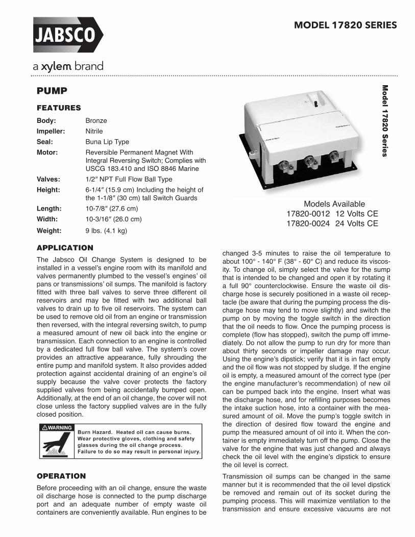
PUMP
FEATURES
Body: BronzeImpeller: NitrileSeal: Buna Lip TypeMotor: Reversible Permanent Magnet With
Integral Reversing Switch; Complies withUSCG 183.410 and ISO 8846 Marine
Valves: 1/2" NPT Full Flow Ball TypeHeight: 6-1/4" (15.9 cm) Including the height of
the 1-1/8" (30 cm) tall Switch GuardsLength: 10-7/8" (27.6 cm)Width: 10-3/16" (26.0 cm)Weight: 9 lbs. (4.1 kg)
APPLICATION
The Jabsco Oil Change System is designed to beinstalled in a vessel’s engine room with its manifold andvalves permanently plumbed to the vessel’s engines’ oilpans or transmissions’ oil sumps. The manifold is factoryfitted with three ball valves to serve three different oilreservoirs and may be fitted with two additional ballvalves to drain up to five oil reservoirs. The system canbe used to remove old oil from an engine or transmissionthen reversed, with the integral reversing switch, to pumpa measured amount of new oil back into the engine ortransmission. Each connection to an engine is controlledby a dedicated full flow ball valve. The system’s coverprovides an attractive appearance, fully shrouding theentire pump and manifold system. It also provides addedprotection against accidental draining of an engine’s oilsupply because the valve cover protects the factory supplied valves from being accidentally bumped open.Additionally, at the end of an oil change, the cover will notclose unless the factory supplied valves are in the fullyclosed position.
OPERATION
Before proceeding with an oil change, ensure the wasteoil discharge hose is connected to the pump dischargeport and an adequate number of empty waste oil containers are conveniently available. Run engines to be
Model 17820 S
eries
Models Available17820-0012 12 Volts CE17820-0024 24 Volts CE
MODEL 17820 SERIES

created during the oil changing process.
INSTALLATION
The Oil Change pump and manifold assembly may be oriented in any position. However, if mounted to avertical surface, it should not be oriented with the pump’smotor below the pump head. This will ensure that,should the seal ever develop a leak, oil from the pumphead will not drip onto the motor. The Oil Changershould be located where the lengths of hose can be kept as short and straight as possible. The pump is self-priming and may be positioned up to three feet abovethe oil source. However, for best operation the pump andmanifold should be mounted at a level that is just slightly above the highest oil level to be changed. Oftenthis is approximately even with the level of the enginemounts. Secure the pump and manifold platform to asolid mounting surface at the four corner attachmentpoints. It is recommended that heavy duty reinforcedtype A fuel hose be used to connect the manifold valveswith the engine pans and transmission sumps. All hoseassemblies should be made with permanent type endconnector fittings similar to hose assemblies for on-boardnatural or propane gas systems.If additional valves are needed, to plumb the system toa maximum of five oil reservoirs, they can be added byremoving the pipe plug(s) in either end of the manifoldand attaching additional valves at these locations. If it is desirable to orient the additional valves in the sameorientation as the three factory supplied valves, toensure maximum performance, it is recommended that a Close Nipple and standard 90° Elbow be fitted to the manifold rather than a Street Elbow. The I.D. of astandard Elbow and Close Nipple is larger and lessrestrictive than a 90° Street Elbow. Apply a couple wrapsof sealing tape to each pipe joint when installing additional valves.When the system is plumbed to all oil reservoirs, eachvalve can be identified with its respective connectionpoint utilizing the assorted labels provided. Select thelabel(s) that best identifies the device to which eachvalve is plumbed then peal it off the sheet of labels andapply it to the top of the system cover over the valve.
WIRING
Connect the unit to an overload protected electricaldistri bu tion panel (circuit breaker or fuse panel) withmarine grade copper stranded wire, sized to match therecommendation in the Electrical Specifications chart.The electrical circuit breaker (or fuse) must also be sizedto match the Electrical Specifications recommendation.The positive and negative wire connections should besecured in place on the electrical terminal block locatednear the end of the valve manifold. The positive (Pos.)and negative (Neg.) terminals of the terminal block areclearly identified. Once the wiring is completed, the elec-trical wires should be secured to a solid surface every
eighteen inches along the length of their run to preventmovement and abrasion.WIRE SIZE (AWG [mm2]) for various conductor lengths
Model Amp Fuse/ Length of run in feet (meters)*
Number Volts Draw Brkr. 0-10(0-3) 10-20(3-6) 20-30(6-9) 30-50(9-15)
17820-0012 12 10 15 16[1.5] 14[2.5] 12[4] 10[6]17820-0024 24 5 8 16[1.5] 16[1.5] 16[1.5] 16[1.5]* The length of run is the total length of both positive and negative conductors
measured from the positive power source to the pump and back to negative.
SERVICEThe Jabsco Oil Change System should provide manyyears of reliable service without the need for regular orscheduled maintenance. However, if sludge shouldbecome lodged anywhere in the system, it can causeexcessive vacuum or pressure on the pump that maydamage the flexible impeller. If this occurs pump perfor-mance will be reduced and it will become necessary tochange the pump’s impeller.Before performing any service work, ensure all the system valves are closed and the power to the pump isturned off and labeled “Do Not Turn On” to guard againstit being accidentally turned back on while service work isbeing performed.
IMPELLER REPLACEMENT
To change the impeller, the system’s cover assemblymust be removed. To do this, remove the cover to baseattachment fasteners (one on each of three sides of thefixed cover and two under the hinged cover over themanifold) and lift the cover assembly from the base.Remove the pump end cover screws, end cover andgasket. Grasp the impeller’s hub with a pair of pliers andpull the old impeller from the impeller bore. Ensure theold gasket material is cleaned from the pump body surface and the end cover.With a rotary motion (to flex the blades of the newimpeller under the cam silhouette in the pump body)push the new impeller into the body until the flat of theimpeller insert aligns with the flat of the shaft. When thetwo flats align, push the impeller firmly into the impellerbore until it bottoms in the bore. Align a new gasket withthe profile of the pump body and position the end coveragainst it and the body. Secure both with the end coverscrews. Position the system cover over the pump andmanifold and secure it to the base at its five attachmentpoints.
SEAL REPLACEMENT
Under normal circumstances, the shaft seal should function properly for several hundred hours of operation.If the seal should ever develop a leak and need to bereplaced, begin the procedure by following the aboveinstructions for changing an impeller. Once the impellerhas been removed, remove the two screws that secure
the pump head to the motor. Detach the Oil ChangeSystem from the surface it is mounted to, so the basecan be raised high enough to access the nuts on theunderside of it that secure the motor to the base andremove the motor attachment fasteners. When themotor is detached from the base, slide the motorstraight back and away from the pump housing. Withthe pump housing still attached to the molded manifoldnipple, support the back side of the pump housing withone hand (keeping it clear of the immediate seal area)and insert a dowel into the impeller end of the pumphousing and against the lip side of the seal. With a firmpush, the seal should be able to be pushed out of theseal bore toward the motor side of the pump housing. Ifthe seal cannot be easily pushed out of the pump housing, it may be necessary to unscrew the pumphousing from the molded nipple of the manifold andremove it to a work bench surface where it can be better supported as the seal is pressed from it. When theseal is removed, ensure the seal bore is clean of alldebris. From the back side of the pump housing, placethe new seal in the seal bore, ensuring the lip of theseal is pointing toward the impeller bore. If the pumphousing is attached to the manifold‘s molded nipple,support the pump housing with one hand, while pressingthe seal into the seal bore until it is firmly seated in thebottom of it. If the pump housing was removed from themanifold, press the seal into the seal bore, wrap themanifold‘s nipple with some sealing tape and reattachthe pump housing to the manifold. Guide the motorshaft through the lip seal and slide it forward until the
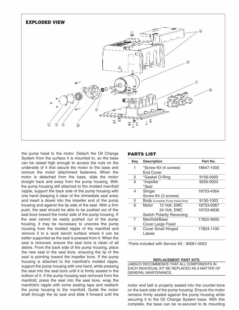
EXPLODED VIEW
9
1 3
4
5
6
7
8
2
PARTS LIST
Key Description Part No.
1 *Screw Kit (4 screws) 18647-1000End Cover
2 *Gasket O-Ring 9156-00003 *Impeller 9200-0023
*Seal 4 Slinger 18753-4364
Screw Kit (3 screws) 5 Body (Complete Pump Head Only) 9130-10036 Motor 12 Volt, EMC 18753-0067
24 Volt, EMC 18753-6636Switch Polarity Reversing
7 Manifold/Base 17822-9000Cover Large Fixed
8 Cover Small Hinged 17824-1100Labels
motor end bell is properly seated into the counter-boreon the back side of the pump housing. Ensure the motorremains firmly seated against the pump housing whilesecuring it to the Oil Change System base. With thiscomplete, the base can be re-secured to its mounting
REPLACEMENT PART KITSJABSCO RECOMMENDS THAT ALL COMPONENTS INEACH INDIVIDUAL KIT BE REPLACED AS A MATTER OFGENERAL MAINTENANCE.
*Parts included with Service Kit : 90061-0053

SECTIONAL DRAWING
THE PRODUCTS DESCRIBED HEREIN ARE SUBJECT TOTHE JABSCO ONE YEAR LIMITED WARRANTY, WHICH ISAVAILABLE FOR YOUR INSPECTION UPON REQUEST.
Jabsco is a trademark of Xylem Inc. or one of its subsidiaries. © 2013 Xylem, Inc. 43000-0705 Rev B 11/2013
www.xylemflowcontrol.comJabsco, 100 Cummings Center, Ste. 535-N, Beverly, MA 01915Tel: +1 978 281 0440 Fax: +1 978 283 2619
Jabsco, Bingley Road, Hoddesdon, Hertfordshire, EN11 0BUTel: +44 (0) 1992 450 145 Fax: +44 (0) 1992 467 132
NHK Jabsco Co Ltd, 3-21-10, Shin - Yokohama Kohoku-ku, Yokohama 222Tel: +81 (0) 45 475 8906 Fax: +81 (0) 45 475 8908
Jabsco GmbH, Oststraße 28, 22844 NorderstedtTel: +49 (0) 40 53 53 73 0 Fax: +49 (0) 49 53 53 73 11
Jabsco Italia, s.r.l., Via Tommaseo, 6, 20059 Vimercate, MilanoTel: +39 039 685 2323 Fax: +39 039 666 307
USA
UK
JAPAN
GERMANY
ITALY