modbus tcp/ip option instruction manual - walchem tcp/ip option instruction manual s800v005 - v013...
TRANSCRIPT
Modbus TCP/IP Option
Instruction Manual s800v005 - v013
s801v004 – v013
s811v010 – v013
s830v005 – v013
WebMaster® Modbus TCP/IP Option
W A L C H E M An Iwaki America Company
Five Boynton Road Hopping Brook Park Holliston, MA 01746 USA
TEL: 508-429-1110 FAX: 508-429-7433 WEB: www.walchem.com
Notice
© 2009 WALCHEM, An Iwaki America Incorporated Company (hereinafter “Walchem”) Five Boynton Road, Holliston, MA 01746 USA (508) 429-1110 All Rights Reserved Printed in USA
Proprietary Material
The information and descriptions contained herein are the property of WALCHEM. Such information and descriptions may not be copied or reproduced by any means, or disseminated or distributed without the express prior written permission of WALCHEM, Five Boynton Road, Holliston, MA 01746.
Statement of Limited Warranty
WALCHEM warrants equipment of its manufacture, and bearing its identification to be free from defects in workmanship and material for a period of 24 months for electronics and 12 months for mechanical parts and electrodes from date of delivery from the factory or authorized distributor under normal use and service and otherwise when such equipment is used in accordance with instructions furnished by WALCHEM and for the purposes disclosed in writing a the time of purchase, if any. WALCHEM’s liability under this warranty shall be limited to replacement or repair, F.O.B. Holliston, MA U.S.A. of any defective equipment or part which, having been returned to WALCHEM, transportation charges prepaid, has been inspected and determined by WALCHEM to be defective. Replacement elastomeric parts and glass components are expendable and are not covered by any warranty.
THIS WARRANTY IS IN LIEU OF ANY OTHER WARRANTY, EITHER EXPRESS OR IMPLIED, AS TO DESCRIPTION, QUALITY, MERCHANTABILITY, and FITNESS FOR ANY PARTICULAR PURPOSE OR USE, OR ANY OTHER MATTER.
180277 Rev F2 Nov 2009
TABLE OF CONTENTS
1.0 SCOPE.......................................................................................................1
2.0 INTRODUCTION........................................................................................1
3.0 OVERVIEW................................................................................................2
4.0 MODBUS/TCP DRIVER.............................................................................2 4.1 MODBUS PROTOCOL .....................................................................................2
4.1.1 TCP ...........................................................................................................2 4.1.2 Function Codes .........................................................................................3
4.2 TCP/IP INTERFACE .........................................................................................4 4.3 DATA MODEL ...................................................................................................4 4.4 DATA REFRESH...............................................................................................5 4.5 DATA ENCODING ............................................................................................5
4.5.1 Binary ........................................................................................................5 4.5.2 16-Bit Word (short) ....................................................................................6 4.5.3 32-Bit Word (int) ........................................................................................6 4.5.4 Float Inverse..............................................................................................6 4.5.5 Strings .......................................................................................................7
4.6 DATA DICTIONARY..........................................................................................7 4.6.1 Addressing (0- or 1-Based) .......................................................................7 4.6.2 Header Data ..............................................................................................7 4.6.3 Alarm Data.................................................................................................8 4.6.4 Status Data..............................................................................................16 4.6.5 Dynamic Data ..........................................................................................19
1
1.0 SCOPE
This document is a User Interface Specification for the WebMaster® Modbus/TCP product feature. This is a mapping of the various dynamic variables to their Modbus/TCP register locations.
This document supports the Modbus feature in the following controller software versions:
S800v005 - v013 s811v010 – v013
S801v004 – v013 s830v005 – v013
2.0 INTRODUCTION
The WebMaster® product supports TCP/IP communications on 3 different network interfaces (USB, modem, and Ethernet). All configurations of set points are accomplished with a computer running a browser (such as Microsoft Internet Explorer) connected to the WebMaster® over one of these interfaces.
The Modbus/TCP option allows the WebMaster® to communicate with PC-based applications such as WonderWare and Intellution HMI/SCADA programs, Building Energy Management systems, Distributed Control Systems (DCS), as well as stand-alone HMI devices. The Modbus/TCP information is only available over the Ethernet interface.
The WebMaster® is a Modbus Server, meaning that it is only capable of responding to requests from the HMI device. The WebMaster® cannot initiate the flow of information, for example, it will not immediately send a new alarm message. It will wait until the HMI device requests the current data contained in specific register locations.
In addition, the HMI software cannot be used to change set points. This is only possible using browser software.
If the HMI device does not directly support Modbus/TCP protocol, then a protocol translation gateway may be required to convert from Modbus/TCP to a protocol that the device supports. Note that Modbus/RTU requires a serial interface, not Ethernet, and therefore is not directly compatible with the WebMaster®.
2
3.0 OVERVIEW
Modbus/TCP is a form of Modbus that uses the TCP/IP layers as a base layer for controlling the communications between different devices.
The Modbus/TCP protocol supports multiple types of data transactions, from reading single bits per transaction, to advanced object-oriented operations. However, to ensure the most compatible system available, the simplest function set is to be made available.
The Modbus/TCP has each transaction type classified in to conformance classes, to ensure consistency and interoperability. Class 0 is the simplest, and allows for reading and writing of multiple 16-bit registers. The Modbus/TCP feature of the WebMaster® will support reading of these 16-bit registers, which allows the WebMaster® to establish a block of data which contains all the process variables, set points, alarms and input/output statuses that are to be made public to a Modbus/TCP client. This block of data is packaged so that it can be read in 16-bit chunks (or registers) at a time, regardless of the type of data within it. In the following sections, the formatting, storing, and reading of this data are described.
4.0 MODBUS/TCP DRIVER
4.1 MODBUS PROTOCOL
The Modbus protocol, as well as the TCP extension, is well documented in the specifications which are available at http://www.modbus.org, a website established by the Modbus Organization for supporting and organizing the Modbus protocol. Only the use of the protocol is documented here.
4.1.1 TCP
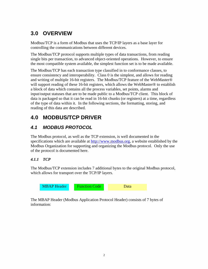
The Modbus/TCP extension includes 7 additional bytes to the original Modbus protocol, which allows for transport over the TCP/IP layers.
MBAP Header Function Code Data
The MBAP Header (Modbus Application Protocol Header) consists of 7 bytes of information:

3
Transaction Identifier 2 bytes identification of Request/Response transaction – copied from request to response
Protocol Identifier 2 bytes 0 = Modbus protocol
Length 2 bytes number of following bytes – includes the unit identifier
Unit Identifier 1 byte identification of remote slave, can be used for broadcasting (not supported)
The Unit Identifier has a special consideration in the WebMaster® implementation. If the value is 0, then the request is considered to be a broadcast message; therefore the packet will be processed, and no response will be generated. If the value is anything else, the packet will be processed and a response will be generated.
The broadcast Unit Identifier address is not supported as of this release, as the only function code supported is Read Holding Registers; therefore, a response is required at all times.
4.1.2 Function Codes
The Modbus/TCP feature only supports Function Code 3 (FC3), Read Multiple Registers, which allows the reading of up to 125 16-bit registers, or quantities, within a single request/response cycle. The 125-register limitation is established for the Modbus/TCP standard to maintain consistency with the original Modbus protocol standard, even though a TCP/IP packet can support more data.
Request
Function Code 1 byte 0x03
Starting Address 2 bytes 0x0000 to 0xFFFF
Quantity of Registers 2 bytes 1 to 125 (0x01 to 0x7D)
Response
Function Code 1 byte 0x03
Byte Count 1 byte 2 x N*
Register Values N* x 2 bytes
*N = quantity of registers
Error
Function Code 1 byte 0x03
Exception Code 1 byte

4
Any other Function Code request will be returned with an error response indicating the Function Code is not supported, as well as a request for too much data or data at a register address that is not present.
4.2 TCP/IP INTERFACE
The Modbus/TCP interface is attached to the TCP/IP stack that is implemented within the WebMaster® product, and will listen to all communications that come in on Modbus/TCP registered port 502.
The Modbus/TCP client uses the standard TCP methods for communicating with the driver, as established by the BSD socket interface: connect(), send(), receive() and close(). Up to 10 connections/sockets are possible at one time. If there are 10 active connections, any attempt at any more connections is ignored.
Once a connection has been established, it will be closed after 1 minute of inactivity.
4.3 DATA MODEL
Modbus bases its data model on a series of tables that have individual characteristics. The four primary tables are:
Primary table data type type of access Discrete Inputs single bit read-only
Coils single bit read-write
Input Registers 16-bits read-only
Holding Registers 16-bits read-write
There is no requirement for how the tables are implemented within the product, but the tables are distinctive because of the method that is used to access them within the protocol.
Since only FC3 is supported in the WebMaster® implementation, only the Holding Registers-type table is required. To access each entry in to the Holding Register table, a starting address (0 indicates the first entry in the table) is required as well as the number of registers that are requested.
The data storage does not need to be consecutive; in fact, this implementation uses multiple ‘blocks’ within the Holding Register table to support future enhancements and additions to the data without changing the location of the data already present.
The Holding Register table is a large structure that contains smaller structures, each containing the specific types of data, and associated with a defined starting address offset for each type of data. The offset allows the driver to determine if the request needs to access data from the specific structure.
5
The data within the WebMaster® system that is to be made public (process variables, set points, alarms and input/output status) is divided in to four structures (header, alarms, status data, and dynamic data). Any time new data needs to be added to the table (upgraded product, different version, etc), the new data is added to the end of the particular structure that corresponds with that type of data.
The data is stored within the tables local to the Modbus/TCP driver, which allows the driver to quickly access it during a request. The tables are indexed in to during a request using the starting address of the request and the defined offset for that structure.
For example, if the structure containing the headers has an defined offset of 0, and is 128 bytes long and a request for starting address 10 with a length of 5 words is received, the 20th through 29th byte within the table are sent to the client.
Once the data is stored within the local tables, the driver does not differentiate what is stored in them. The Modbus/TCP client needs to know what data is stored in which register locations to be able to retrieve it, process it, and/or display it.
4.4 DATA REFRESH
To ensure that the Modbus/TCP client has the most recent data available to it, the Modbus/TCP periodically refreshes the data by reading the selected data and storing it in the specific locations within the tables.
The refresh is performed at a periodic rate to ensure data is new, yet not too often to affect the performance of the WebMaster® product.
4.5 DATA ENCODING
Modbus uses a ‘big-endian’ representation for addresses and data items. This means that when a numerical quantity larger than a single byte is transmitted, the MOST significant byte is sent first. The following sub-topics describe the different types of encoding and show how the data is encoded as it is within the Modbus/TCP packet. Most client drivers will extract the data from the packet in the correct format for use/display within the client environment.
4.5.1 Binary
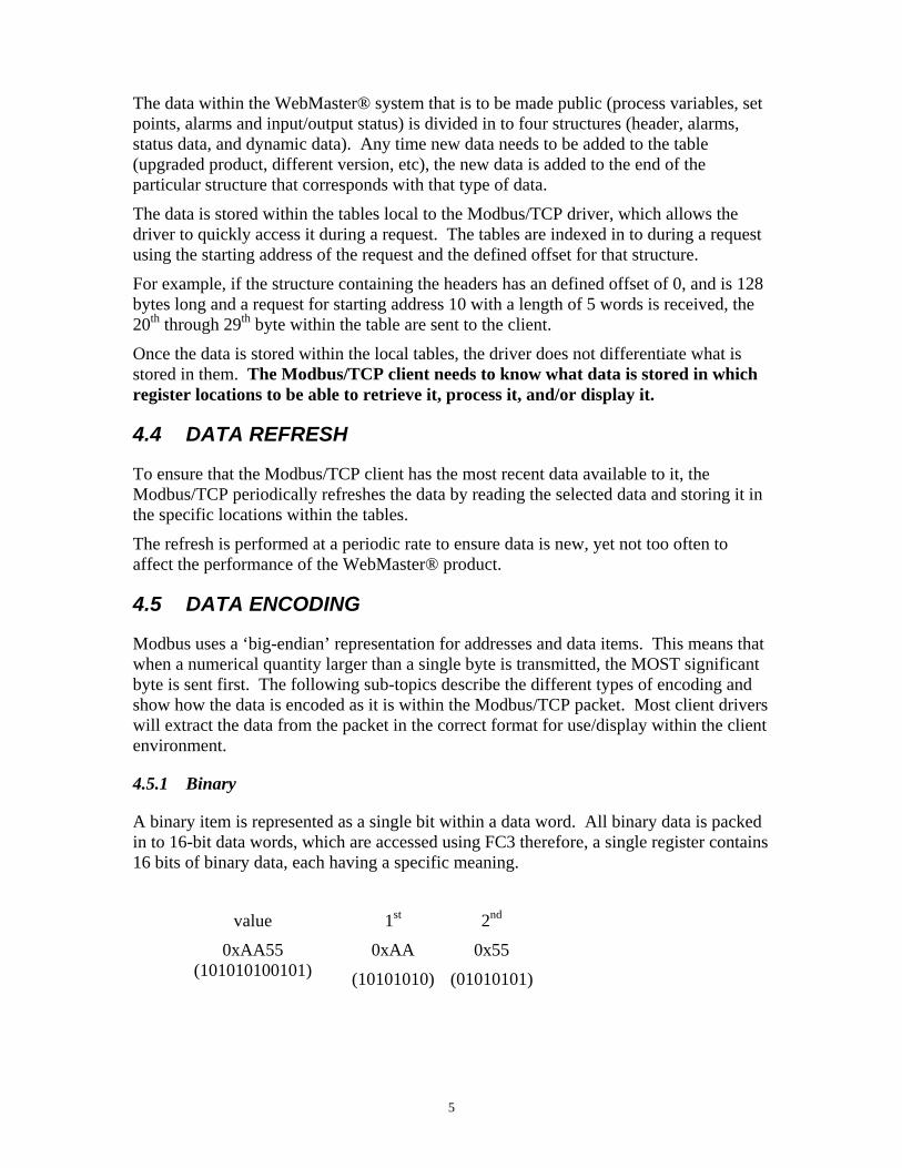
A binary item is represented as a single bit within a data word. All binary data is packed in to 16-bit data words, which are accessed using FC3 therefore, a single register contains 16 bits of binary data, each having a specific meaning.
value 1st 2nd
0xAA55 (101010100101)
0xAA
(10101010)
0x55
(01010101)
6
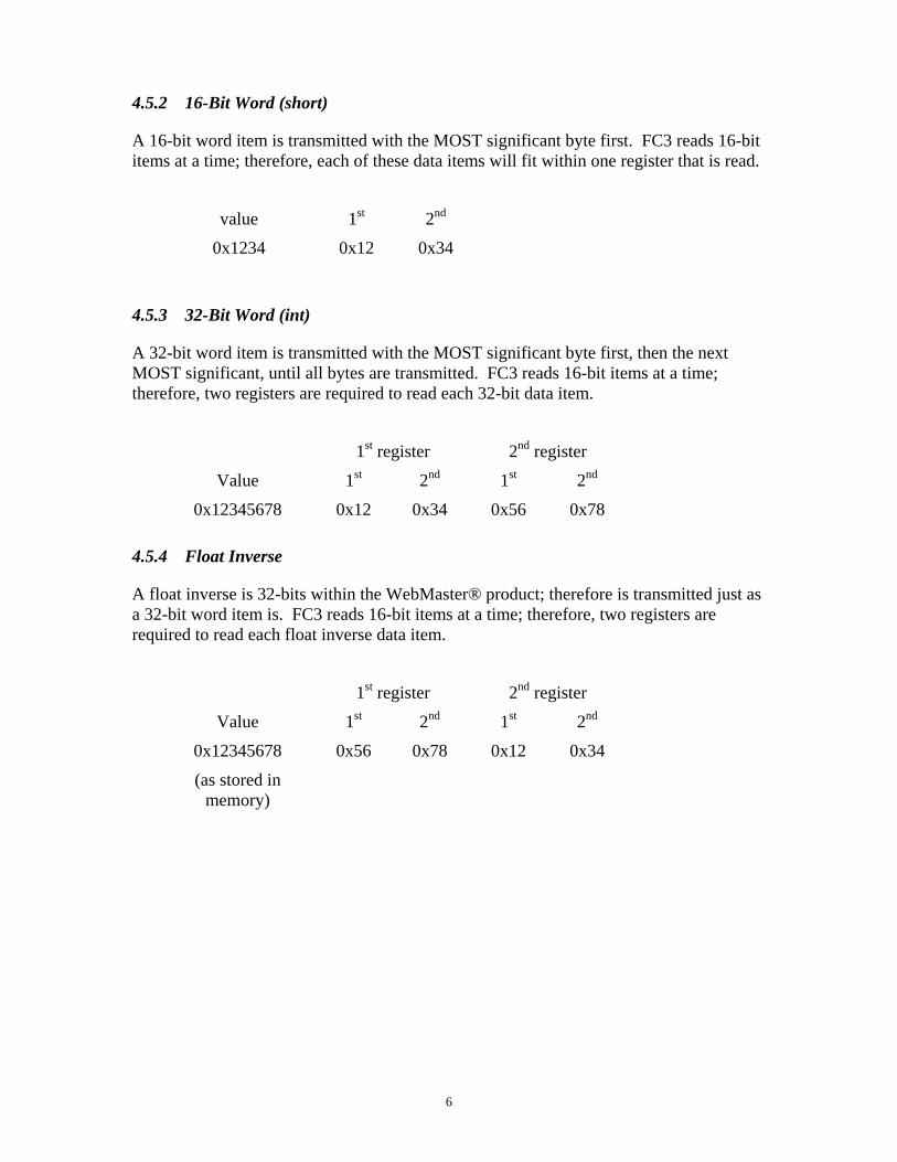
4.5.2 16-Bit Word (short)
A 16-bit word item is transmitted with the MOST significant byte first. FC3 reads 16-bit items at a time; therefore, each of these data items will fit within one register that is read.
value 1st 2nd
0x1234 0x12 0x34
4.5.3 32-Bit Word (int)
A 32-bit word item is transmitted with the MOST significant byte first, then the next MOST significant, until all bytes are transmitted. FC3 reads 16-bit items at a time; therefore, two registers are required to read each 32-bit data item.
1st register 2nd register
Value 1st 2nd 1st 2nd
0x12345678 0x12 0x34 0x56 0x78
4.5.4 Float Inverse
A float inverse is 32-bits within the WebMaster® product; therefore is transmitted just as a 32-bit word item is. FC3 reads 16-bit items at a time; therefore, two registers are required to read each float inverse data item.
1st register 2nd register
Value 1st 2nd 1st 2nd
0x12345678
(as stored in memory)
0x56 0x78 0x12 0x34

7
4.5.5 Strings
A string is a group of 8-bit data items having a fixed length. The first character of a string is transmitted first, followed by the remaining characters. FC3 reads 16-bit items at a time; therefore, a single register contains two characters of the string. To simply string storage/transfer, each string should be of an even-byte length.
1st register 2nd register 3rd register 4th register
value 1st 2nd 1st 2nd 1st 2nd 1st 2nd
‘Walchem’ ‘W’ ‘a’ ‘l’ ‘c’ ‘h’ ‘e’ ‘m’ ?
4.6 DATA DICTIONARY
The following tables detail the Modbus addresses required to access each item of the public data.
4.6.1 Addressing (0- or 1-Based)
The addressing within the Modbus/TCP protocol (that is, the data within the physical packet) is 0-based, meaning the first element/item to be accessed is referenced by address 0. The Modbus standard for handling and displaying the data is 1-based, meaning the first element/data item to be access is referenced by address 1.
Most client applications handle this by having the user enter the 1-based number, and then subtract 1 to revert to the 0-based addressing required at the protocol level.
Some client applications allow the user to enter the 0-based number, or a combination, depending on how it is configured.
The addresses defined within the following table are 1-based, as the majority of the client applications work with this method.
4.6.2 Header Data
Header data consists of strings that are available to describe miscellaneous parts of the product. Refer to section 4.5.5 Strings for the method to extract the string data.
For example, to read the Date item, a Read Holding Register request is generated with address 40033 and a register quantity of 12.
8
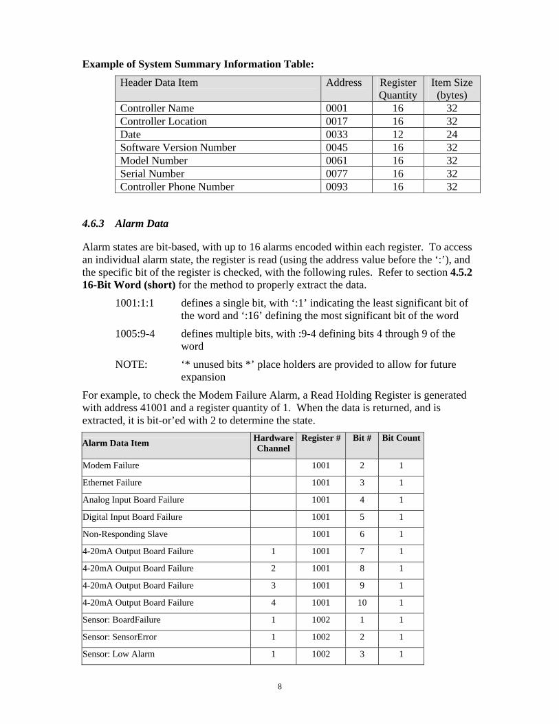
Example of System Summary Information Table:
Header Data Item Address Register Quantity
Item Size (bytes)
Controller Name 0001 16 32 Controller Location 0017 16 32 Date 0033 12 24 Software Version Number 0045 16 32 Model Number 0061 16 32 Serial Number 0077 16 32 Controller Phone Number 0093 16 32
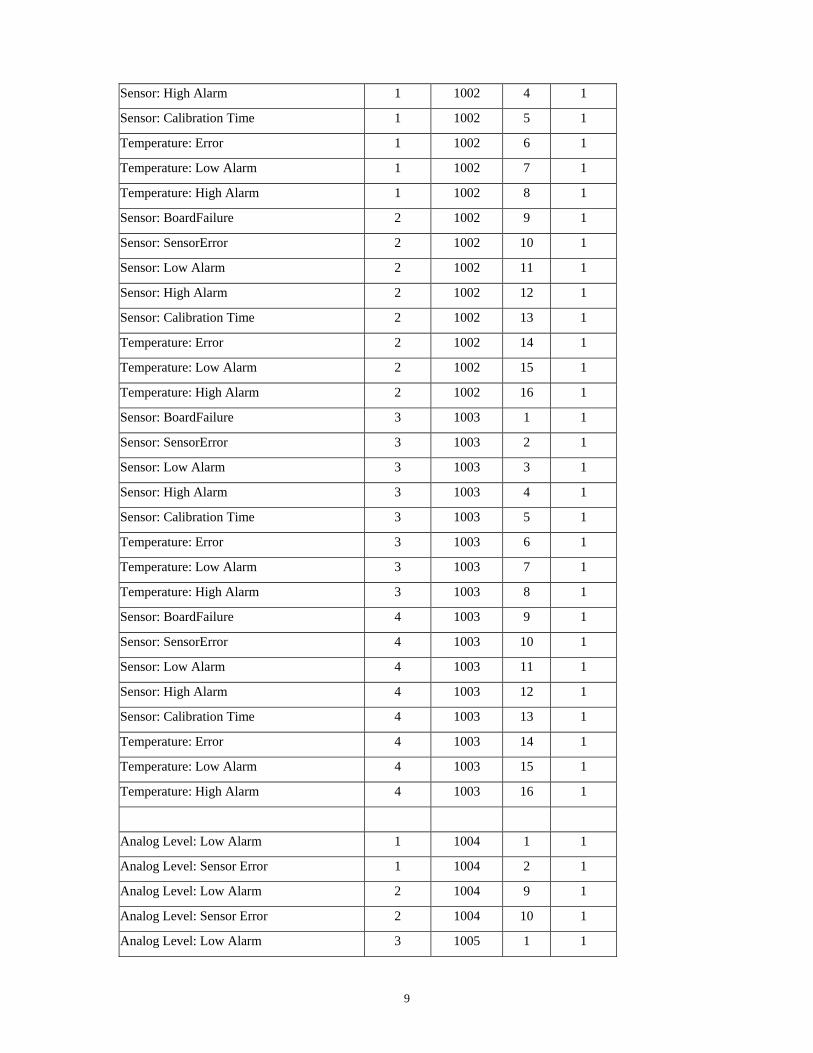
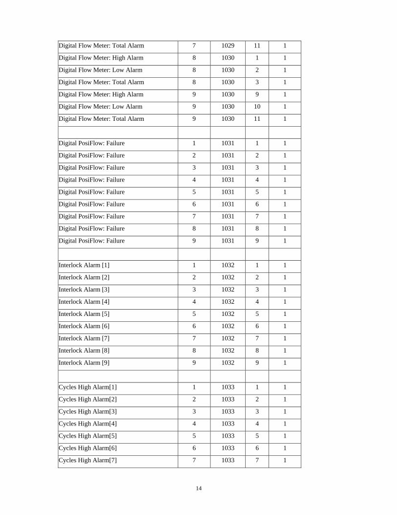
4.6.3 Alarm Data
Alarm states are bit-based, with up to 16 alarms encoded within each register. To access an individual alarm state, the register is read (using the address value before the ‘:’), and the specific bit of the register is checked, with the following rules. Refer to section 4.5.2 16-Bit Word (short) for the method to properly extract the data.
1001:1:1 defines a single bit, with ‘:1’ indicating the least significant bit of the word and ‘:16’ defining the most significant bit of the word
1005:9-4 defines multiple bits, with :9-4 defining bits 4 through 9 of the word
NOTE: ‘* unused bits *’ place holders are provided to allow for future expansion
For example, to check the Modem Failure Alarm, a Read Holding Register is generated with address 41001 and a register quantity of 1. When the data is returned, and is extracted, it is bit-or’ed with 2 to determine the state.
Alarm Data Item Hardware Channel
Register # Bit # Bit Count
Modem Failure 1001 2 1
Ethernet Failure 1001 3 1
Analog Input Board Failure 1001 4 1
Digital Input Board Failure 1001 5 1
Non-Responding Slave 1001 6 1
4-20mA Output Board Failure 1 1001 7 1
4-20mA Output Board Failure 2 1001 8 1
4-20mA Output Board Failure 3 1001 9 1
4-20mA Output Board Failure 4 1001 10 1
Sensor: BoardFailure 1 1002 1 1
Sensor: SensorError 1 1002 2 1
Sensor: Low Alarm 1 1002 3 1
9
Sensor: High Alarm 1 1002 4 1
Sensor: Calibration Time 1 1002 5 1
Temperature: Error 1 1002 6 1
Temperature: Low Alarm 1 1002 7 1
Temperature: High Alarm 1 1002 8 1
Sensor: BoardFailure 2 1002 9 1
Sensor: SensorError 2 1002 10 1
Sensor: Low Alarm 2 1002 11 1
Sensor: High Alarm 2 1002 12 1
Sensor: Calibration Time 2 1002 13 1
Temperature: Error 2 1002 14 1
Temperature: Low Alarm 2 1002 15 1
Temperature: High Alarm 2 1002 16 1
Sensor: BoardFailure 3 1003 1 1
Sensor: SensorError 3 1003 2 1
Sensor: Low Alarm 3 1003 3 1
Sensor: High Alarm 3 1003 4 1
Sensor: Calibration Time 3 1003 5 1
Temperature: Error 3 1003 6 1
Temperature: Low Alarm 3 1003 7 1
Temperature: High Alarm 3 1003 8 1
Sensor: BoardFailure 4 1003 9 1
Sensor: SensorError 4 1003 10 1
Sensor: Low Alarm 4 1003 11 1
Sensor: High Alarm 4 1003 12 1
Sensor: Calibration Time 4 1003 13 1
Temperature: Error 4 1003 14 1
Temperature: Low Alarm 4 1003 15 1
Temperature: High Alarm 4 1003 16 1
Analog Level: Low Alarm 1 1004 1 1
Analog Level: Sensor Error 1 1004 2 1
Analog Level: Low Alarm 2 1004 9 1
Analog Level: Sensor Error 2 1004 10 1
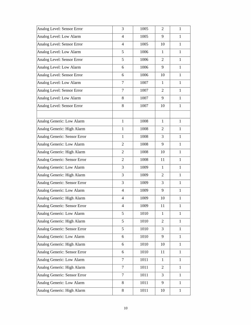
Analog Level: Low Alarm 3 1005 1 1
10
Analog Level: Sensor Error 3 1005 2 1
Analog Level: Low Alarm 4 1005 9 1
Analog Level: Sensor Error 4 1005 10 1
Analog Level: Low Alarm 5 1006 1 1
Analog Level: Sensor Error 5 1006 2 1
Analog Level: Low Alarm 6 1006 9 1
Analog Level: Sensor Error 6 1006 10 1
Analog Level: Low Alarm 7 1007 1 1
Analog Level: Sensor Error 7 1007 2 1
Analog Level: Low Alarm 8 1007 9 1
Analog Level: Sensor Error 8 1007 10 1
Analog Generic: Low Alarm 1 1008 1 1
Analog Generic: High Alarm 1 1008 2 1
Analog Generic: Sensor Error 1 1008 3 1
Analog Generic: Low Alarm 2 1008 9 1
Analog Generic: High Alarm 2 1008 10 1
Analog Generic: Sensor Error 2 1008 11 1
Analog Generic: Low Alarm 3 1009 1 1
Analog Generic: High Alarm 3 1009 2 1
Analog Generic: Sensor Error 3 1009 3 1
Analog Generic: Low Alarm 4 1009 9 1
Analog Generic: High Alarm 4 1009 10 1
Analog Generic: Sensor Error 4 1009 11 1
Analog Generic: Low Alarm 5 1010 1 1
Analog Generic: High Alarm 5 1010 2 1
Analog Generic: Sensor Error 5 1010 3 1
Analog Generic: Low Alarm 6 1010 9 1
Analog Generic: High Alarm 6 1010 10 1
Analog Generic: Sensor Error 6 1010 11 1
Analog Generic: Low Alarm 7 1011 1 1
Analog Generic: High Alarm 7 1011 2 1
Analog Generic: Sensor Error 7 1011 3 1
Analog Generic: Low Alarm 8 1011 9 1
Analog Generic: High Alarm 8 1011 10 1
11
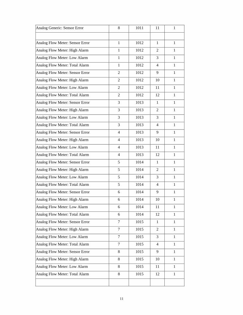
Analog Generic: Sensor Error 8 1011 11 1
Analog Flow Meter: Sensor Error 1 1012 1 1
Analog Flow Meter: High Alarm 1 1012 2 1
Analog Flow Meter: Low Alarm 1 1012 3 1
Analog Flow Meter: Total Alarm 1 1012 4 1
Analog Flow Meter: Sensor Error 2 1012 9 1
Analog Flow Meter: High Alarm 2 1012 10 1
Analog Flow Meter: Low Alarm 2 1012 11 1
Analog Flow Meter: Total Alarm 2 1012 12 1
Analog Flow Meter: Sensor Error 3 1013 1 1
Analog Flow Meter: High Alarm 3 1013 2 1
Analog Flow Meter: Low Alarm 3 1013 3 1
Analog Flow Meter: Total Alarm 3 1013 4 1
Analog Flow Meter: Sensor Error 4 1013 9 1
Analog Flow Meter: High Alarm 4 1013 10 1
Analog Flow Meter: Low Alarm 4 1013 11 1
Analog Flow Meter: Total Alarm 4 1013 12 1
Analog Flow Meter: Sensor Error 5 1014 1 1
Analog Flow Meter: High Alarm 5 1014 2 1
Analog Flow Meter: Low Alarm 5 1014 3 1
Analog Flow Meter: Total Alarm 5 1014 4 1
Analog Flow Meter: Sensor Error 6 1014 9 1
Analog Flow Meter: High Alarm 6 1014 10 1
Analog Flow Meter: Low Alarm 6 1014 11 1
Analog Flow Meter: Total Alarm 6 1014 12 1
Analog Flow Meter: Sensor Error 7 1015 1 1
Analog Flow Meter: High Alarm 7 1015 2 1
Analog Flow Meter: Low Alarm 7 1015 3 1
Analog Flow Meter: Total Alarm 7 1015 4 1
Analog Flow Meter: Sensor Error 8 1015 9 1
Analog Flow Meter: High Alarm 8 1015 10 1
Analog Flow Meter: Low Alarm 8 1015 11 1
Analog Flow Meter: Total Alarm 8 1015 12 1
12
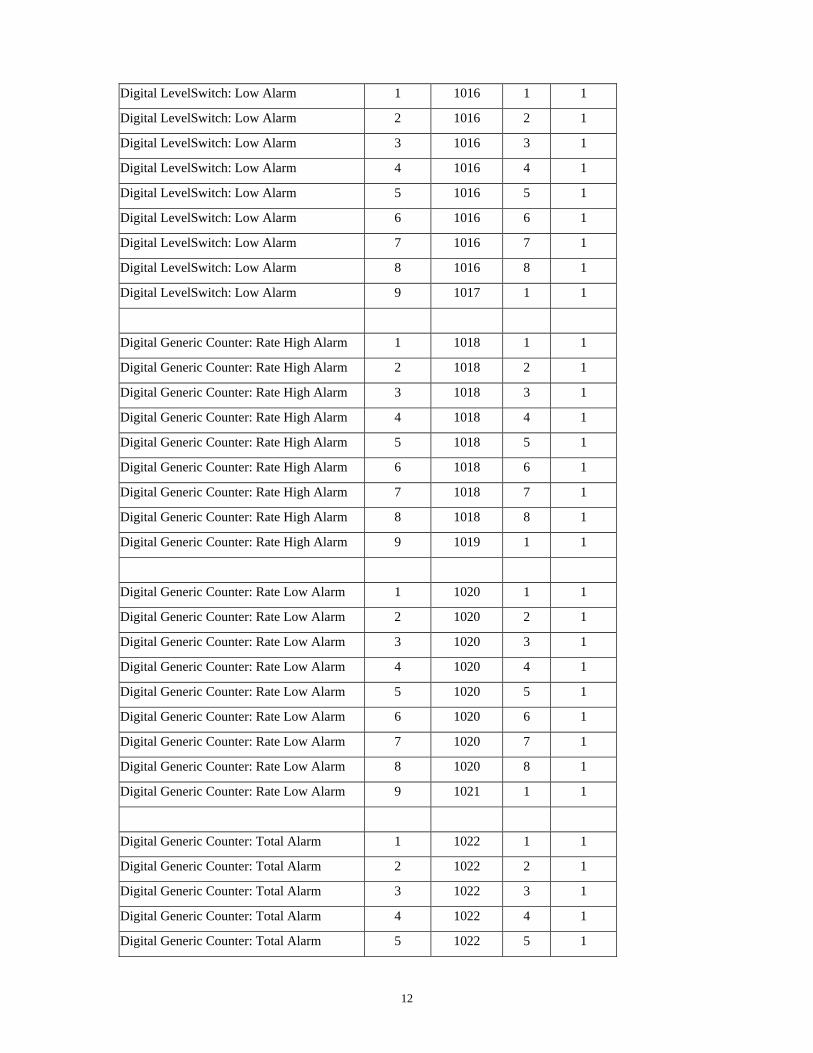
Digital LevelSwitch: Low Alarm 1 1016 1 1
Digital LevelSwitch: Low Alarm 2 1016 2 1
Digital LevelSwitch: Low Alarm 3 1016 3 1
Digital LevelSwitch: Low Alarm 4 1016 4 1
Digital LevelSwitch: Low Alarm 5 1016 5 1
Digital LevelSwitch: Low Alarm 6 1016 6 1
Digital LevelSwitch: Low Alarm 7 1016 7 1
Digital LevelSwitch: Low Alarm 8 1016 8 1
Digital LevelSwitch: Low Alarm 9 1017 1 1
Digital Generic Counter: Rate High Alarm 1 1018 1 1
Digital Generic Counter: Rate High Alarm 2 1018 2 1
Digital Generic Counter: Rate High Alarm 3 1018 3 1
Digital Generic Counter: Rate High Alarm 4 1018 4 1
Digital Generic Counter: Rate High Alarm 5 1018 5 1
Digital Generic Counter: Rate High Alarm 6 1018 6 1
Digital Generic Counter: Rate High Alarm 7 1018 7 1
Digital Generic Counter: Rate High Alarm 8 1018 8 1
Digital Generic Counter: Rate High Alarm 9 1019 1 1
Digital Generic Counter: Rate Low Alarm 1 1020 1 1
Digital Generic Counter: Rate Low Alarm 2 1020 2 1
Digital Generic Counter: Rate Low Alarm 3 1020 3 1
Digital Generic Counter: Rate Low Alarm 4 1020 4 1
Digital Generic Counter: Rate Low Alarm 5 1020 5 1
Digital Generic Counter: Rate Low Alarm 6 1020 6 1
Digital Generic Counter: Rate Low Alarm 7 1020 7 1
Digital Generic Counter: Rate Low Alarm 8 1020 8 1
Digital Generic Counter: Rate Low Alarm 9 1021 1 1
Digital Generic Counter: Total Alarm 1 1022 1 1
Digital Generic Counter: Total Alarm 2 1022 2 1
Digital Generic Counter: Total Alarm 3 1022 3 1
Digital Generic Counter: Total Alarm 4 1022 4 1
Digital Generic Counter: Total Alarm 5 1022 5 1

13
Digital Generic Counter: Total Alarm 6 1022 6 1
Digital Generic Counter: Total Alarm 7 1022 7 1
Digital Generic Counter: Total Alarm 8 1022 8 1
Digital Generic Counter: Total Alarm 9 1023 1 1
Digital.Generic Input: Alarm 1 1024 1 1
Digital.Generic Input: Alarm 2 1024 2 1
Digital.Generic Input: Alarm 3 1024 3 1
Digital.Generic Input: Alarm 4 1024 4 1
Digital.Generic Input: Alarm 5 1024 5 1
Digital.Generic Input: Alarm 6 1024 6 1
Digital.Generic Input: Alarm 7 1024 7 1
Digital.Generic Input: Alarm 8 1024 8 1
Digital.Generic Input: Alarm 9 1025 1 1
Digital Flow Meter: High Alarm 1 1026 9 1
Digital Flow Meter: Low Alarm 1 1026 10 1
Digital Flow Meter: Total Alarm 1 1026 11 1
Digital Flow Meter: High Alarm 2 1027 1 1
Digital Flow Meter: Low Alarm 2 1027 2 1
Digital Flow Meter: Total Alarm 2 1027 3 1
Digital Flow Meter: High Alarm 3 1027 9 1
Digital Flow Meter: Low Alarm 3 1027 10 1
Digital Flow Meter: Total Alarm 3 1027 11 1
Digital Flow Meter: High Alarm 4 1028 1 1
Digital Flow Meter: Low Alarm 4 1028 2 1
Digital Flow Meter: Total Alarm 4 1028 3 1
Digital Flow Meter: High Alarm 5 1028 9 1
Digital Flow Meter: Low Alarm 5 1028 10 1
Digital Flow Meter: Total Alarm 5 1028 11 1
Digital Flow Meter: High Alarm 6 1029 1 1
Digital Flow Meter: Low Alarm 6 1029 2 1
Digital Flow Meter: Total Alarm 6 1029 3 1
Digital Flow Meter: High Alarm 7 1029 9 1
Digital Flow Meter: Low Alarm 7 1029 10 1
14
Digital Flow Meter: Total Alarm 7 1029 11 1
Digital Flow Meter: High Alarm 8 1030 1 1
Digital Flow Meter: Low Alarm 8 1030 2 1
Digital Flow Meter: Total Alarm 8 1030 3 1
Digital Flow Meter: High Alarm 9 1030 9 1
Digital Flow Meter: Low Alarm 9 1030 10 1
Digital Flow Meter: Total Alarm 9 1030 11 1
Digital PosiFlow: Failure 1 1031 1 1
Digital PosiFlow: Failure 2 1031 2 1
Digital PosiFlow: Failure 3 1031 3 1
Digital PosiFlow: Failure 4 1031 4 1
Digital PosiFlow: Failure 5 1031 5 1
Digital PosiFlow: Failure 6 1031 6 1
Digital PosiFlow: Failure 7 1031 7 1
Digital PosiFlow: Failure 8 1031 8 1
Digital PosiFlow: Failure 9 1031 9 1
Interlock Alarm [1] 1 1032 1 1
Interlock Alarm [2] 2 1032 2 1
Interlock Alarm [3] 3 1032 3 1
Interlock Alarm [4] 4 1032 4 1
Interlock Alarm [5] 5 1032 5 1
Interlock Alarm [6] 6 1032 6 1
Interlock Alarm [7] 7 1032 7 1
Interlock Alarm [8] 8 1032 8 1
Interlock Alarm [9] 9 1032 9 1
Cycles High Alarm[1] 1 1033 1 1
Cycles High Alarm[2] 2 1033 2 1
Cycles High Alarm[3] 3 1033 3 1
Cycles High Alarm[4] 4 1033 4 1
Cycles High Alarm[5] 5 1033 5 1
Cycles High Alarm[6] 6 1033 6 1
Cycles High Alarm[7] 7 1033 7 1

15
Cycles High Alarm[8] 8 1033 8 1
Cycles Low Alarm[1] 1 1034 1 1
Cycles Low Alarm[2] 2 1034 2 1
Cycles Low Alarm[3] 3 1034 3 1
Cycles Low Alarm[4] 4 1034 4 1
Cycles Low Alarm[5] 5 1034 5 1
Cycles Low Alarm[6] 6 1034 6 1
Cycles Low Alarm[7] 7 1034 7 1
Cycles Low Alarm[8] 8 1034 8 1
Biocide Skipped Alarm[1] 1 1035 1 1
Biocide Skipped Alarm[2] 2 1035 2 1
Biocide Skipped Alarm[3] 3 1035 3 1
Biocide Skipped Alarm[4] 4 1035 4 1
Biocide Skipped Alarm[5] 5 1035 5 1
Biocide Skipped Alarm[6] 6 1035 6 1
Biocide Skipped Alarm[7] 7 1035 7 1
Biocide Skipped Alarm[8] 8 1035 8 1
ORP Spike Skipped Alarm[1] 1 1036 1 1
ORP Spike Skipped Alarm[2] 2 1036 2 1
ORP Spike Skipped Alarm[3] 3 1036 3 1
ORP Spike Skipped Alarm[4] 4 1036 4 1
ORP Spike Skipped Alarm[5] 5 1036 5 1
ORP Spike Skipped Alarm[6] 6 1036 6 1
ORP Spike Skipped Alarm[7] 7 1036 7 1
ORP Spike Skipped Alarm[8] 8 1036 8 1
Output Timeout Alarm 1 1037 1 1
Output Timeout Alarm 2 1037 2 1
Output Timeout Alarm 3 1037 3 1
Output Timeout Alarm 4 1037 4 1
Output Timeout Alarm 5 1037 5 1
Output Timeout Alarm 6 1037 6 1
Output Timeout Alarm 7 1037 7 1
16
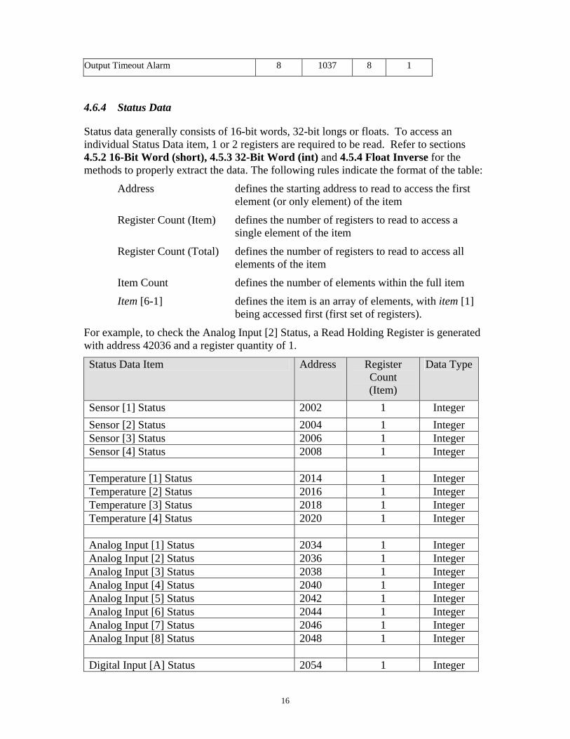
Output Timeout Alarm 8 1037 8 1
4.6.4 Status Data
Status data generally consists of 16-bit words, 32-bit longs or floats. To access an individual Status Data item, 1 or 2 registers are required to be read. Refer to sections 4.5.2 16-Bit Word (short), 4.5.3 32-Bit Word (int) and 4.5.4 Float Inverse for the methods to properly extract the data. The following rules indicate the format of the table:
Address defines the starting address to read to access the first element (or only element) of the item
Register Count (Item) defines the number of registers to read to access a single element of the item
Register Count (Total) defines the number of registers to read to access all elements of the item
Item Count defines the number of elements within the full item
Item [6-1] defines the item is an array of elements, with item [1] being accessed first (first set of registers).
For example, to check the Analog Input [2] Status, a Read Holding Register is generated with address 42036 and a register quantity of 1.
Status Data Item Address Register Count (Item)
Data Type
Sensor [1] Status 2002 1 Integer
Sensor [2] Status 2004 1 Integer Sensor [3] Status 2006 1 Integer Sensor [4] Status 2008 1 Integer Temperature [1] Status 2014 1 Integer Temperature [2] Status 2016 1 Integer Temperature [3] Status 2018 1 Integer Temperature [4] Status 2020 1 Integer Analog Input [1] Status 2034 1 Integer Analog Input [2] Status 2036 1 Integer Analog Input [3] Status 2038 1 Integer Analog Input [4] Status 2040 1 Integer Analog Input [5] Status 2042 1 Integer Analog Input [6] Status 2044 1 Integer Analog Input [7] Status 2046 1 Integer Analog Input [8] Status 2048 1 Integer Digital Input [A] Status 2054 1 Integer
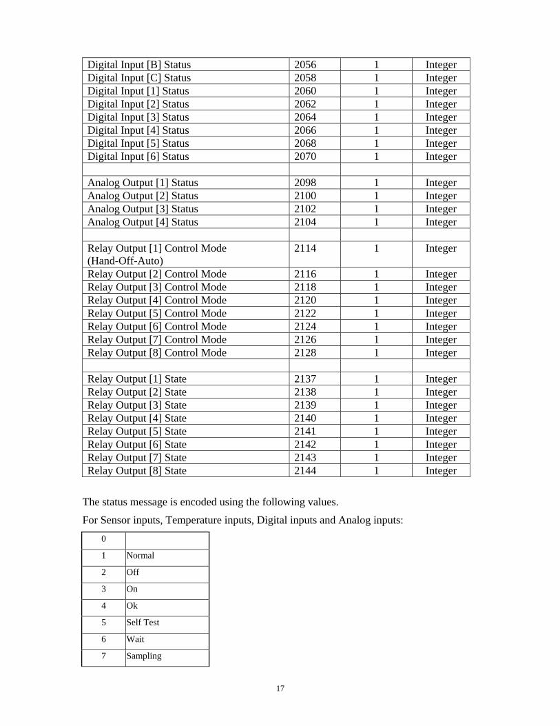
17
Digital Input [B] Status 2056 1 Integer Digital Input [C] Status 2058 1 Integer Digital Input [1] Status 2060 1 Integer Digital Input [2] Status 2062 1 Integer Digital Input [3] Status 2064 1 Integer Digital Input [4] Status 2066 1 Integer Digital Input [5] Status 2068 1 Integer Digital Input [6] Status 2070 1 Integer Analog Output [1] Status 2098 1 Integer Analog Output [2] Status 2100 1 Integer Analog Output [3] Status 2102 1 Integer Analog Output [4] Status 2104 1 Integer Relay Output [1] Control Mode (Hand-Off-Auto)
2114 1 Integer
Relay Output [2] Control Mode 2116 1 Integer Relay Output [3] Control Mode 2118 1 Integer Relay Output [4] Control Mode 2120 1 Integer Relay Output [5] Control Mode 2122 1 Integer Relay Output [6] Control Mode 2124 1 Integer Relay Output [7] Control Mode 2126 1 Integer Relay Output [8] Control Mode 2128 1 Integer Relay Output [1] State 2137 1 Integer Relay Output [2] State 2138 1 Integer Relay Output [3] State 2139 1 Integer Relay Output [4] State 2140 1 Integer Relay Output [5] State 2141 1 Integer Relay Output [6] State 2142 1 Integer Relay Output [7] State 2143 1 Integer Relay Output [8] State 2144 1 Integer
The status message is encoded using the following values.
For Sensor inputs, Temperature inputs, Digital inputs and Analog inputs:
0
1 Normal
2 Off
3 On
4 Ok
5 Self Test
6 Wait
7 Sampling
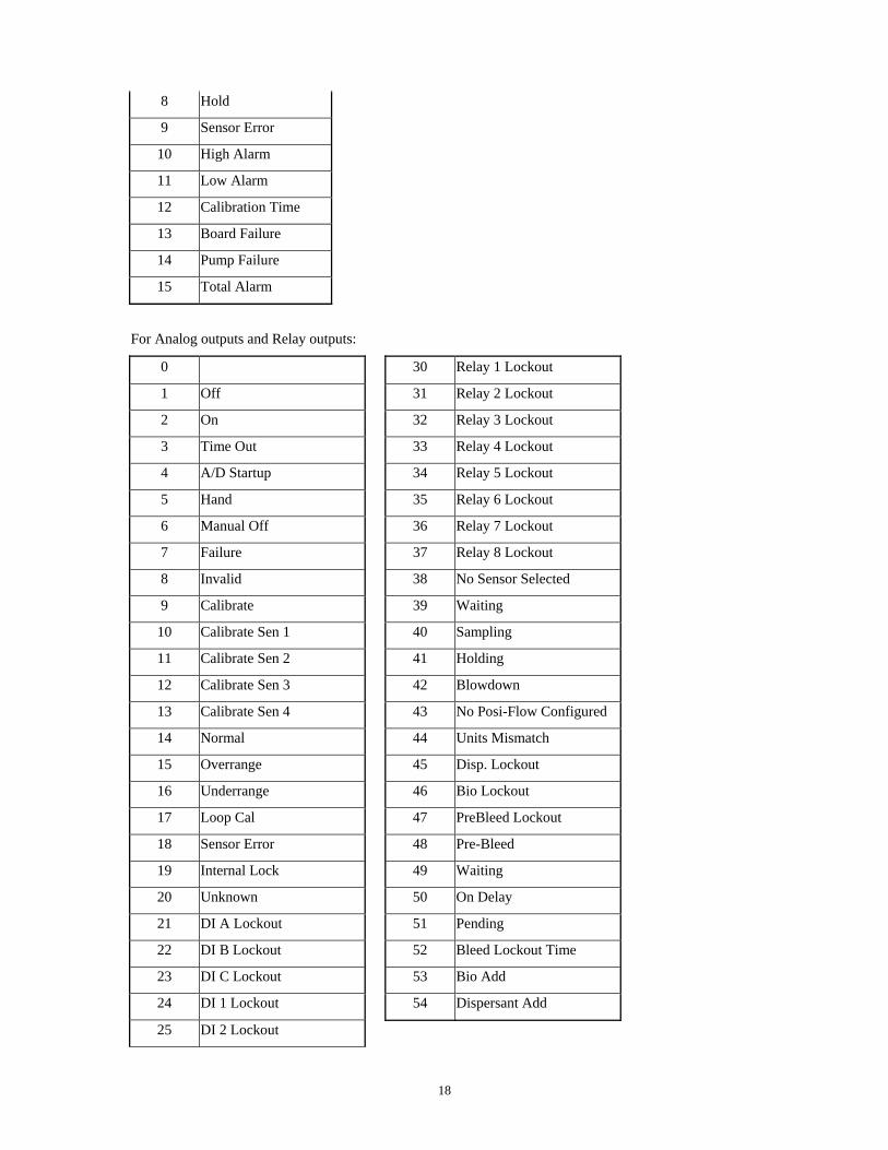
18
8 Hold
9 Sensor Error
10 High Alarm
11 Low Alarm
12 Calibration Time
13 Board Failure
14 Pump Failure
15 Total Alarm
For Analog outputs and Relay outputs:
0 30 Relay 1 Lockout
1 Off 31 Relay 2 Lockout
2 On 32 Relay 3 Lockout
3 Time Out 33 Relay 4 Lockout
4 A/D Startup 34 Relay 5 Lockout
5 Hand 35 Relay 6 Lockout
6 Manual Off 36 Relay 7 Lockout
7 Failure 37 Relay 8 Lockout
8 Invalid 38 No Sensor Selected
9 Calibrate 39 Waiting
10 Calibrate Sen 1 40 Sampling
11 Calibrate Sen 2 41 Holding
12 Calibrate Sen 3 42 Blowdown
13 Calibrate Sen 4 43 No Posi-Flow Configured
14 Normal 44 Units Mismatch
15 Overrange 45 Disp. Lockout
16 Underrange 46 Bio Lockout
17 Loop Cal 47 PreBleed Lockout
18 Sensor Error 48 Pre-Bleed
19 Internal Lock 49 Waiting
20 Unknown 50 On Delay
21 DI A Lockout 51 Pending
22 DI B Lockout 52 Bleed Lockout Time
23 DI C Lockout 53 Bio Add
24 DI 1 Lockout 54 Dispersant Add
25 DI 2 Lockout
19
26 DI 3 Lockout
27 DI 4 Lockout
28 DI 5 Lockout
29 DI 6 Lockout
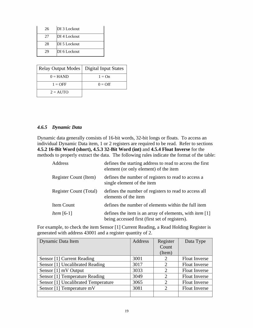
Relay Output Modes Digital Input States
0 = HAND 1 = On
1 = OFF 0 = Off
2 = AUTO
4.6.5 Dynamic Data
Dynamic data generally consists of 16-bit words, 32-bit longs or floats. To access an individual Dynamic Data item, 1 or 2 registers are required to be read. Refer to sections 4.5.2 16-Bit Word (short), 4.5.3 32-Bit Word (int) and 4.5.4 Float Inverse for the methods to properly extract the data. The following rules indicate the format of the table:
Address defines the starting address to read to access the first element (or only element) of the item
Register Count (Item) defines the number of registers to read to access a single element of the item
Register Count (Total) defines the number of registers to read to access all elements of the item
Item Count defines the number of elements within the full item
Item [6-1] defines the item is an array of elements, with item [1] being accessed first (first set of registers).
For example, to check the item Sensor [1] Current Reading, a Read Holding Register is generated with address 43001 and a register quantity of 2.
Dynamic Data Item Address Register Count (Item)
Data Type
Sensor [1] Current Reading 3001 2 Float Inverse Sensor [1] Uncalibrated Reading 3017 2 Float Inverse Sensor [1] mV Output 3033 2 Float Inverse Sensor [1] Temperature Reading 3049 2 Float Inverse Sensor [1] Uncalibrated Temperature 3065 2 Float Inverse Sensor [1] Temperature mV 3081 2 Float Inverse

20
Sensor [2] Current Reading 3003 2 Float Inverse Sensor [2] Uncalibrated Reading 3019 2 Float Inverse Sensor [2] mV Output 3035 2 Float Inverse Sensor [2] Temperature Reading 3051 2 Float Inverse Sensor [2] Uncalibrated Temperature 3067 2 Float Inverse Sensor [2] Temperature mV 3083 2 Float Inverse Sensor [3] Current Reading 3005 2 Float Inverse Sensor [3] Uncalibrated Reading 3021 2 Float Inverse Sensor [3] mV Output 3037 2 Float Inverse Sensor [3] Temperature Reading 3053 2 Float Inverse Sensor [3] Uncalibrated Temperature 3069 2 Float Inverse Sensor [3] Temperature mV 3085 2 Float Inverse Sensor [4] Current Reading 3007 2 Float Inverse Sensor [4] Uncalibrated Reading 3023 2 Float Inverse Sensor [4] mV Output 3039 2 Float Inverse Sensor [4] Temperature Reading 3055 2 Float Inverse Sensor [4] Uncalibrated Temperature 3071 2 Float Inverse Sensor [4] Temperature mV 3087 2 Float Inverse Analog Input [1] Measured Value 3097 2 Float Inverse Analog Input [1] Raw mA 3129 2 Float Inverse Analog Input [1] Total * 3161 2 Float Inverse Analog Input [2] Measured Value 3099 2 Float Inverse Analog Input [2] Raw mA 3131 2 Float Inverse Analog Input [2] Total * 3163 2 Float Inverse Analog Input [3] Measured Value 3101 2 Float Inverse Analog Input [3] Raw mA 3133 2 Float Inverse Analog Input [3] Total * 3165 2 Float Inverse Analog Input [4] Measured Value 3103 2 Float Inverse Analog Input [4] Raw mA 3135 2 Float Inverse Analog Input [4] Total * 3167 2 Float Inverse Analog Input [5] Measured Value 3105 2 Float Inverse Analog Input [5] Raw mA 3137 2 Float Inverse Analog Input [5] Total * 3169 2 Float Inverse Analog Input [6] Measured Value 3107 2 Float Inverse Analog Input [6] Raw mA 3139 2 Float Inverse Analog Input [6] Total * 3171 2 Float Inverse Analog Input [7] Measured Value 3109 2 Float Inverse Analog Input [7] Raw mA 3141 2 Float Inverse Analog Input [7] Total * 3173 2 Float Inverse Analog Input [8] Measured Value 3111 2 Float Inverse Analog Input [8] Raw mA 3143 2 Float Inverse Analog Input [8] Total * 3175 2 Float Inverse * NOTE: Total is only applicable for Flow
21
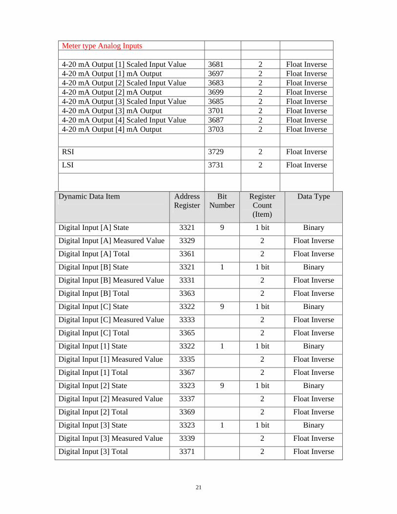
Meter type Analog Inputs 4-20 mA Output [1] Scaled Input Value 3681 2 Float Inverse 4-20 mA Output [1] mA Output 3697 2 Float Inverse 4-20 mA Output [2] Scaled Input Value 3683 2 Float Inverse 4-20 mA Output [2] mA Output 3699 2 Float Inverse 4-20 mA Output [3] Scaled Input Value 3685 2 Float Inverse 4-20 mA Output [3] mA Output 3701 2 Float Inverse 4-20 mA Output [4] Scaled Input Value 3687 2 Float Inverse 4-20 mA Output [4] mA Output 3703 2 Float Inverse
RSI 3729 2 Float Inverse
LSI 3731 2 Float Inverse
Dynamic Data Item Address Register
Bit Number
Register Count (Item)
Data Type
Digital Input [A] State 3321 9 1 bit Binary
Digital Input [A] Measured Value 3329 2 Float Inverse
Digital Input [A] Total 3361 2 Float Inverse
Digital Input [B] State 3321 1 1 bit Binary
Digital Input [B] Measured Value 3331 2 Float Inverse
Digital Input [B] Total 3363 2 Float Inverse
Digital Input [C] State 3322 9 1 bit Binary
Digital Input [C] Measured Value 3333 2 Float Inverse
Digital Input [C] Total 3365 2 Float Inverse
Digital Input [1] State 3322 1 1 bit Binary
Digital Input [1] Measured Value 3335 2 Float Inverse
Digital Input [1] Total 3367 2 Float Inverse
Digital Input [2] State 3323 9 1 bit Binary
Digital Input [2] Measured Value 3337 2 Float Inverse
Digital Input [2] Total 3369 2 Float Inverse
Digital Input [3] State 3323 1 1 bit Binary
Digital Input [3] Measured Value 3339 2 Float Inverse
Digital Input [3] Total 3371 2 Float Inverse

22
Digital Input [4] State 3324 9 1 bit Binary
Digital Input [4] Measured Value 3341 2 Float Inverse
Digital Input [4] Total 3373 2 Float Inverse
Digital Input [5] State 3324 1 1 bit Binary
Digital Input [5] Measured Value 3343 2 Float Inverse
Digital Input [5] Total 3375 2 Float Inverse
Digital Input [6] State 3325 9 1 bit Binary
Digital Input [6] Measured Value 3345 2 Float Inverse
Digital Input [6] Total 3377 2 Float Inverse
NOTE: State only applies to Interlock, Level Switch or Generic Input Types.
0 = Open, 1 = Closed
NOTE: Measured Value only applies to Generic Counter, Paddlewheel Flow Meter and PosiFlow type inputs
NOTE: Total does not apply to Interlock, Level Switch or Generic Input types
Relay [1] Interlocking Another 3739 9 1 bit Binary
Relay [2] Interlocking Another 3739 10 1 bit Binary
Relay [3] Interlocking Another 3739 11 1 bit Binary
Relay [4] Interlocking Another 3739 12 1 bit Binary
Relay [5] Interlocking Another 3739 13 1 bit Binary
Relay [6] Interlocking Another 3739 14 1 bit Binary
Relay [7] Interlocking Another 3739 15 1 bit Binary
Relay [8] Interlocking Another 3739 16 1 bit Binary
1 = Interlocking, 2 = Not Interlocking
Relay [1] Accumulated Makeup 3741 2 Float Inverse
Relay [2] Accumulated Makeup 3743 2 Float Inverse
Relay [3] Accumulated Makeup 3745 2 Float Inverse
Relay [4] Accumulated Makeup 3747 2 Float Inverse
Relay [5] Accumulated Makeup 3749 2 Float Inverse

23
Relay [6] Accumulated Makeup 3751 2 Float Inverse
Relay [7] Accumulated Makeup 3753 2 Float Inverse
Relay [8] Accumulated Makeup 3755 2 Float Inverse
Not Applicable to all relay control modes
Relay [1] Accumulated Bleed 3765 2 Float Inverse
Relay [2] Accumulated Bleed 3767 2 Float Inverse
Relay [3] Accumulated Bleed 3769 2 Float Inverse
Relay [4] Accumulated Bleed 3771 2 Float Inverse
Relay [5] Accumulated Bleed 3773 2 Float Inverse
Relay [6] Accumulated Bleed 3775 2 Float Inverse
Relay [7] Accumulated Bleed 3777 2 Float Inverse
Relay [8] Accumulated Bleed 3779 2 Float Inverse
Not Applicable to all relay control modes
Relay [1] Current Week 3790 1 Integer
Relay [2] Current Week 3792 1 Integer
Relay [3] Current Week 3794 1 Integer
Relay [4] Current Week 3796 1 Integer
Relay [5] Current Week 3798 1 Integer
Relay [6] Current Week 3800 1 Integer
Relay [7] Current Week 3802 1 Integer
Relay [8] Current Week 3804 1 Integer
Not Applicable to all relay control modes
Relay [1] Current Set Point 3814 1 Integer
Relay [2] Current Set Point 3816 1 Integer
Relay [3] Current Set Point 3818 1 Integer
Relay [4] Current Set Point 3820 1 Integer
Relay [5] Current Set Point 3822 1 Integer
Relay [6] Current Set Point 3824 1 Integer
Relay [7] Current Set Point 3826 1 Integer
Relay [8] Current Set Point 3828 1 Integer
24
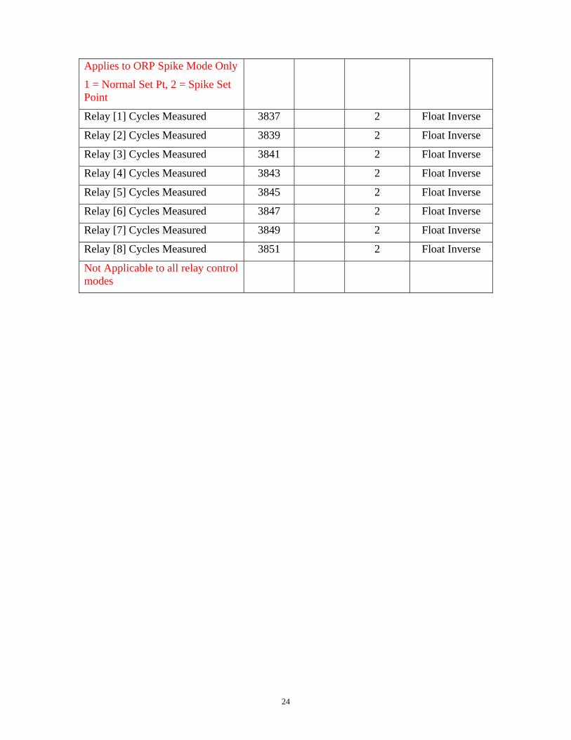
Applies to ORP Spike Mode Only
1 = Normal Set Pt, 2 = Spike Set Point
Relay [1] Cycles Measured 3837 2 Float Inverse
Relay [2] Cycles Measured 3839 2 Float Inverse
Relay [3] Cycles Measured 3841 2 Float Inverse
Relay [4] Cycles Measured 3843 2 Float Inverse
Relay [5] Cycles Measured 3845 2 Float Inverse
Relay [6] Cycles Measured 3847 2 Float Inverse
Relay [7] Cycles Measured 3849 2 Float Inverse
Relay [8] Cycles Measured 3851 2 Float Inverse
Not Applicable to all relay control modes