modbus master/slave serial and ethernet communication...
TRANSCRIPT
MODBUS MASTER/SLAVE Serial and Ethernet
Communication Server
for Microsoft Windows and InTouch Applications
User Manual
Ver 1.x Rev 2.2 DR 380 10 DR 380 11
KLINKMANN AUTOMATION P.O. Box 38
FIN-00371 Helsinki Finland tel. int. + 358 9 5404940 fax int. + 358 9 5413541
www.klinkmann.com
Klinkmann Automation MODBUS MASTER/SLAVE Serial and Ethernet Communication Server i
MODBUS MASTER/SLAVE Serial&Ethernet Comm. Server Ver 1.x User Manual Rev 2.2 380xxm22
Table Of Contents
Overview ........................................................................................................................ 1
Communication Protocols .............................................................................................. 1
Accessing Remote Items via the Server ........................................................................ 3
Installing the MODBUS MASTER/SLAVE Server .......................................................... 4
Installing the Server ................................................................................................... 4
Installing the I/O Server Infrastructure ........................................................................ 5
Configuring the MODBUS MASTER/SLAVE Server ...................................................... 5
Server Settings Command ......................................................................................... 6
Com Port Settings Command .................................................................................... 8
Saving of the MODBUS Server Configuration File ..................................................... 9
Configuration File Location ........................................................................................ 9
Socket Settings Command ......................................................................................... 10
Topic Definition Command ......................................................................................... 13
Item Names ................................................................................................................... 23
Modbus Function 7 (Read Exception Status) Support ............................................... 24
Modbus Function 8 (Diagnostics) Support ................................................................. 25
Notes on Data Processing in Slave Mode .................................................................. 26
Monitoring and Controlling Communication with MODBUS Bus ................................ 27
Using the MODBUS Server with OPC Clients ............................................................... 29
Configuring DCOM ..................................................................................................... 30
Configuring DCOM to access MODBUS Server as a local OPC Server ................. 30
Configuring DCOM to access MODBUS Server as a remote OPC Server ............. 31
Most frequent errors when configuring DCOM ....................................................... 32
Running MODBUS "OPC & DDE" version as Windows NT Service .......................... 33
Using MODBUS with OPCLink Server ....................................................................... 33
OPCLink Topic Definition ........................................................................................ 33
Accessing MODBUS Items via the OPCLink Server .............................................. 34
Using the MODBUS Server with Suite Link and DDE Clients ........................................ 35
Using the MODBUS Server with InTouch ...................................................................... 35
Defining the Access Names ....................................................................................... 35
Defining the Tag names ............................................................................................. 37
Monitoring the Status of Communication with InTouch .............................................. 39
Notes on Using Microsoft Excel ..................................................................................... 40
Reading Values into Excel Spreadsheets .................................................................. 40
Writing Values to MODBUS MASTER/SLAVE Points ................................................ 40
Troubleshooting ............................................................................................................. 42
WIN.INI entries ........................................................................................................... 42
Troubleshooting menu ............................................................................................... 44
Internal Logger ........................................................................................................... 45
Klinkmann Automation MODBUS MASTER/SLAVE Serial and Ethernet Communication Server 1
MODBUS MASTER/SLAVE Serial&Ethernet Comm. Server Ver 1.x User Manual Rev 2.2 380xxm22
MODBUS MASTER/SLAVE Serial and Ethernet
Communication Server Overview The MODBUS MASTER/SLAVE Serial and Ethernet Communicati on Server (hereafter referred to as the “MODBUS MASTER/SLAVE Server” or “MODBUS Server” or “MODBUS” or “Server”) is a Microsoft Windows 32-bit application program that acts as a communication protocol Server and allows other Windows application programs access to data from MODBUS network using the RS-232 serial and/or TCP/IP interface. The Server can act either as a MODBUS master device or a MODBUS slave device. Any Microsoft Windows program that is capable of acting as a DDE, FastDDE , SuiteLink or OPC Client may use the MODBUS MASTER/SLAVE Server. There are two different MODBUS Server versions described in this manual: - Server version (ordering number DR 380 10), supporting SuiteLink, FastDDE and
DDE protocols; this version hereafter is referred to as the "Suite Link & DDE " version. - Server version (ordering number DR 380 11), supporting OPC and DDE protocols; this
version hereafter is referred to as the "OPC & DDE" version; Each of above mentioned MODBUS Server version has two sub-versions: TCP Client version and TCP Server version: the TCP Client version is suitable for serial and Ethernet wired connections and TCP Server is specially adjusted for use in GPRS wireless communications. The separate installation package is supplied for each sub-version of the Server. In all cases the name of Server executable file is MODBUS.EXE. All further information in this manual is same for all versions of the Server, with the exception of few points where communication protocol specific features are explained.
Communication Protocols Dynamic Data Exchange (DDE) is a communication protocol developed by Microsoft to allow applications in the Windows environment to send/receive data and instructions to/from each other. It implements a client-server relationship between two concurrently running applications. The server application provides the data and accepts requests from any other application interested in its data. Requesting applications are called clients. Some applications such as Wonderware InTouch and Microsoft Excel can simultaneously be both a client and a server. FastDDE provides a means of packing many proprietary Wonderware DDE messages into a single Microsoft DDE message. This packing improves efficiency and performance by reducing the total number of DDE transactions required between a client and a server. Although Wonderware's FastDDE has extended the usefulness of DDE for the industry, this extension is being pushed to its performance constraints in distributed environments.
Klinkmann Automation MODBUS MASTER/SLAVE Serial and Ethernet Communication Server 2
MODBUS MASTER/SLAVE Serial&Ethernet Comm. Server Ver 1.x User Manual Rev 2.2 380xxm22
The MODBUS MASTER/SLAVE Server “Suite Link & DDE version” supports the FastDDE Version 3 - an extension to Wonderware’s proprietary FastDDE Version 2. This extension supports the transfer of Value Time Quality (VTQ) information. The original DDE and FastDDE Version 2 formats are still supported, providing full backward compatibility with older DDE clients. FastDDE Version 3 works on Windows 9x systems as well as Windows NT systems. NetDDE extends the standard Windows DDE functionality to include communication over local area networks and through serial ports. Network extensions are available to allow DDE links between applications running on different computers connected via networks or modems. For example, NetDDE supports DDE between applications running on IBM compatible computers connected via LAN or modem and DDE-aware applications running on non-PC based platforms under operating environments such as VMS and UNIX. SuiteLink uses a TCP/IP based protocol and is designed by Wonderware specifically to meet industrial needs such as data integrity, high-throughput, and easier diagnostics. This protocol standard is only supported on Microsoft Windows NT 4.0 or higher. SuiteLink is not a replacement for DDE, FastDDE, or NetDDE. The protocol used between a client and a server depends on your network connections and configurations. SuiteLink was designed to be the industrial data network distribution standard and provides the following features: · Value Time Quality (VTQ) places a time stamp and quality indicator on all data values delivered to VTQ-aware clients. · Extensive diagnostics of the data throughput, server loading, computer resource consumption, and network transport are made accessible through the Microsoft Windows NT operating system Performance Monitor. This feature is critical for the scheme and maintenance of distributed industrial networks. · Consistent high data volumes can be maintained between applications regardless if the applications are on a single node or distributed over a large node count. · The network transport protocol is TCP/IP using Microsoft’s standard WinSock interface. OPC (OLE for Process Control) is an open interface standard to provide data from a data source and communicate the data to any client application in a common standard way. The OPC is based on Microsoft OLE, COM and DCOM technologies and enables simple and standardized data interchange between the industrial or office sector and the production sector. From general point of view many aspects of OPC are similar to DDE, but main difference is in the implementation by using Microsoft's COM (Component Object Model) technology. It enables fast exchange with process automation data and OPC open interface allows access to data from OPC Server in same standard way from OPC client applications supplied by different developers. For more information on the basics of OPC, please refer to the OPC Specification . The OPC Data Access Custom Interface Specification is maintained by OPC Foundation , the current specification is 2.05a dated June 2002 (3.00 dated March 2003). The OPC support for MODBUS MASTER/SLAVE Server “OPC & DDE” version is implemented based on FactorySoft OPC Server Development Toolkit and it conforms to OPC Data Access Custom Interface Specification 2.04. The MODBUS
Klinkmann Automation MODBUS MASTER/SLAVE Serial and Ethernet Communication Server 3
MODBUS MASTER/SLAVE Serial&Ethernet Comm. Server Ver 1.x User Manual Rev 2.2 380xxm22
MASTER/SLAVE Server “OPC & DDE” version is tested for compliance and is compatible with OPC Foundation OPC Data Access Compliance Test Tool. The Suite Link, FastDDE (Version 3) and DDE support for MODBUS MASTER/SLAVE Communication Server is implemented by Wonderware I/O Server Toolkit ver. 7,2,1,6. The FastDDE (Version 2) and DDE support for MODBUS Server "OPC & DDE" version is implemented by Wonderware I/O Server Toolkit ver. 5.0 (008).
Accessing Remote Items via the Server The communication protocol addresses an element of data in a conversation that uses a three-part naming convention that includes the application name , topic name and item name . The following briefly describes each portion of this naming convention: application name The name of the Windows program (server) that will be accessing the data element. In the case of data coming from or going to a MODBUS node via this Server, the application portion of the address is MODBUS. topic name Meaningful name of communication entity, that is referred also as “Logical device”. Commonly the name considers entire MODBUS node but in more intricate applications separate data and control item groups on the same node can be accessed by different topics. For example, NODE5 is an ordinary topic name for the fifth node on the MODBUS bus. Note! You can define multiple topic names for the same device (node) to poll different items at different rates. item name A specific data element within the specified topic. For example, when using this Server, items can be individual operands (registers, binary inputs, binary outputs) in the MODBUS node. The term "point" is used interchangeably with the term "item" in this User Manual. For more information on item names, see the Item Names section later in this manual.
Klinkmann Automation MODBUS MASTER/SLAVE Serial and Ethernet Communication Server 4
MODBUS MASTER/SLAVE Serial&Ethernet Comm. Server Ver 1.x User Manual Rev 2.2 380xxm22
Installing the MODBUS MASTER/SLAVE Server Installing the Server The MODBUS MASTER/SLAVE Server installation package is supplied as a self-extracting archive 38010xxx.EXE (“Suite Link & DDE” version) or 38011xxx.EXE (“OPC & DDE” version), where xxx is the current (latest) version of the Server. To install the MODBUS MASTER/SLAVE Server from the self-extracting archive, run the 38010xxx.EXE or 38011xxx.EXE and proceed as directed by the OPC Array Extractor Setup program. Note:
All MS Windows (both NT/2000/XP and 9x) applications using Microsoft’s shared DLLs (e.g. MFC42.DLL and MSVCRT.DLL) must be closed before installing the MODBUS Server “OPC & DDE” version. Otherwise there can be problems with MODBUS Server registration as OPC server. If during the MODBUS Server “OPC & DDE” version installation some warning messages about shared DLLs are displayed, then it is quite possible the MODBUS Server registration as OPC server failed. In this case after system reboot the MODBUS Server registration as OPC server can be done by starting the MODBUS Server manually with special command line parameter added: “MODBUS.EXE /Regserver”.
When installation is finished, the subdirectory specified as a folder where to install the MODBUS MASTER/SLAVE Server files will contain the following files: MODBUS.EXE The MODBUS MASTER/SLAVE Server Program. This is a
Microsoft Windows 32-bit application program.
MODBUS.HLP The MODBUS Server Help file.
MODBUS.CFG An example configuration file.
LICENSE.TXT
Klinkmann Automation software license file.
KLSERVER.DLL
Dynamic Link Library necessary for “OPC & DDE”version of the Server.
WWDLG32.DLL
Dynamic Link Library necessary only for “OPC & DDE”version of the Server.
TCPWORK.DLL Dynamic Link Library necessary for Ethernet communication. To uninstall the MODBUS MASTER/SLAVE Server, start Control Panel, select “Add/Remove Programs” and select the “MODBUS SL and DDE Server” or “MODBUS OPC and DDE Server” from the list of available software products. Click on “Add/Remove…” and proceed as directed by the UnInstallShield program. Notes: 1. The MODBUS MASTER/SLAVE Server is developed with Wonderware I/O Server
Toolkit (ver 7,2,1,6) and needs the Wonderware FS 2000 Common Components to
Klinkmann Automation MODBUS MASTER/SLAVE Serial and Ethernet Communication Server 5
MODBUS MASTER/SLAVE Serial&Ethernet Comm. Server Ver 1.x User Manual Rev 2.2 380xxm22
be installed on computer where MODBUS MASTER/SLAVE Server is running. If using Wonderware InTouch 8.0 or newer, install the FS 2000 Common Components before installing InTouch (see also Wonderware Tech Notes 404 and 313).
2. If MODBUS MASTER/SLAVE Server “Suite Link & DDE” version will run on PC where Wonderware FS2000 Common Components are not installed then a special I/O Server Infrastructure installation package can be obtained from Klinkmann Automation (see Installing the I/O Server Infrastructure section below). This I/O Server Infrastructure installation package contains the minimum set of software needed to run the MODBUS MASTER/SLAVE Server “Suite Link & DDE” version and these infrastructure files must be installed prior to executing the Server.
3. The HASP key is needed for full time running of MODBUS MASTER/SLAVE Server. The HASP Driver setup is performed during the Server setup. Without HASP Driver installed the Server will run only 1 hour (with all features enabled).
Installing the I/O Server Infrastructure The I/O Server Infrastructure installation package can be supplied: 1) As a self-extracting archive (IOServerInfrastructure.exe) if downloaded from
Klinkmann’s web site(http://www.klinkmann.com). 2. On one distribution disk (floppy). To install the I/O Server Infrastructure from the self-extracting archive, run the IOServerInfrastructure.exe and proceed as directed by the I/O Server Infrastructure Setup program. To install the I/O Server Infrastructure from the distribution disk, on MS Windows NT: 1. Insert the I/O Server Infrastructure disk into a floppy drive A: or B:. 2. Select the Run command under the Start menu. 3. Type “A:SETUP” or “B:SETUP”. 4. Click on OK. 5. Proceed as directed by the I/O Server Infrastructure Setup program. To uninstall the I/O Server Infrastructure, start Control Panel, select “Add/Remove Programs” and select the “IO Server Infrastructure” from the list of available software products. Click on “Add/Remove…” and proceed as directed by the UnInstallShield program. Note: The I/O Server Infrastructure installation will be rejected if Wonderware FS2000 Common Components are already installed on same computer.
Configuring the MODBUS MASTER/SLAVE Server After the MODBUS MASTER/SLAVE Server is initially installed, a little of configuration is required. Configuring the Server automatically creates MODBUS.CFG file that holds all of the topics (nodes) definitions entered, as well as the communication port configurations. This file will be placed automatically in the same directory in which the Server is located unless the path where the configuration file will be placed is specified via the /Configure/Server Settings... command.
Klinkmann Automation MODBUS MASTER/SLAVE Serial and Ethernet Communication Server 6
MODBUS MASTER/SLAVE Serial&Ethernet Comm. Server Ver 1.x User Manual Rev 2.2 380xxm22
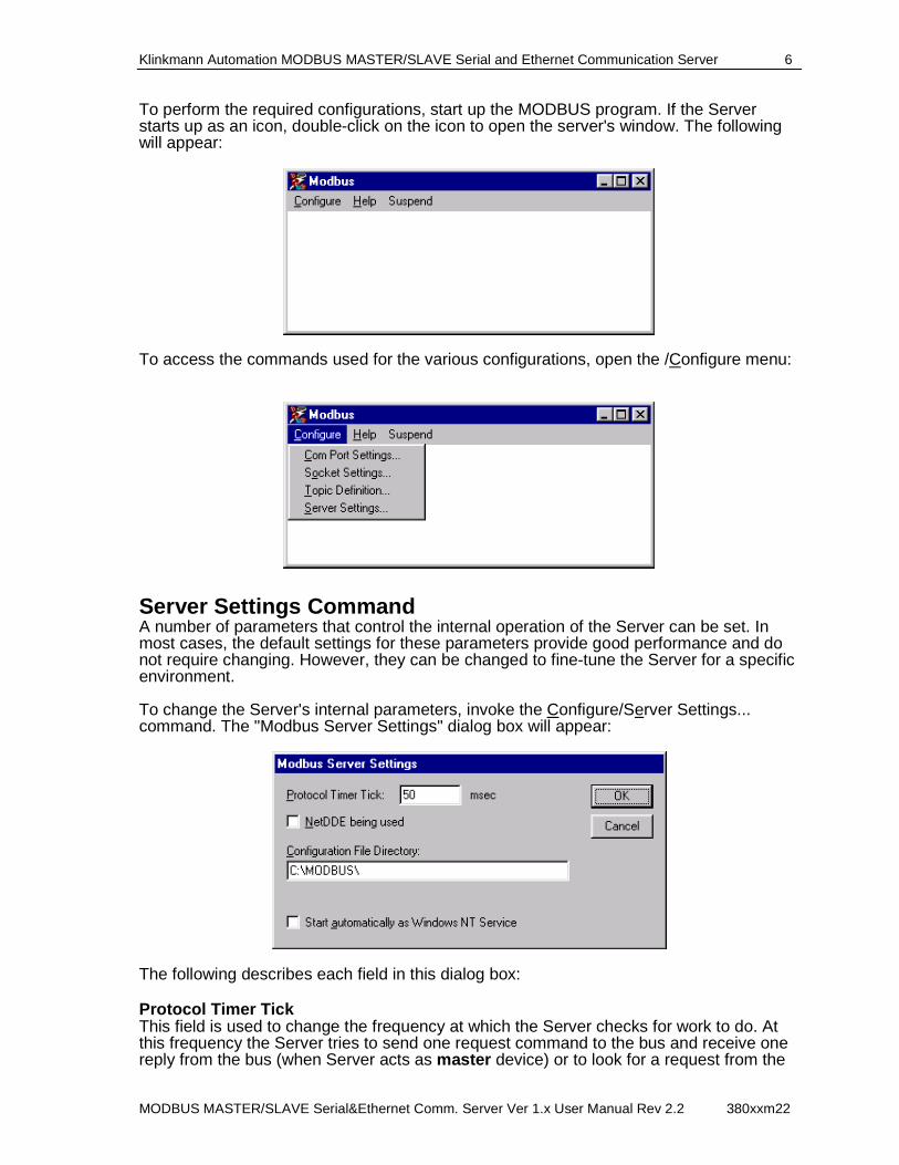
To perform the required configurations, start up the MODBUS program. If the Server starts up as an icon, double-click on the icon to open the server's window. The following will appear:
To access the commands used for the various configurations, open the /Configure menu:
Server Settings Command A number of parameters that control the internal operation of the Server can be set. In most cases, the default settings for these parameters provide good performance and do not require changing. However, they can be changed to fine-tune the Server for a specific environment. To change the Server's internal parameters, invoke the Configure/Server Settings... command. The "Modbus Server Settings" dialog box will appear:
The following describes each field in this dialog box: Protocol Timer Tick This field is used to change the frequency at which the Server checks for work to do. At this frequency the Server tries to send one request command to the bus and receive one reply from the bus (when Server acts as master device) or to look for a request from the
Klinkmann Automation MODBUS MASTER/SLAVE Serial and Ethernet Communication Server 7
MODBUS MASTER/SLAVE Serial&Ethernet Comm. Server Ver 1.x User Manual Rev 2.2 380xxm22
bus and send the reply to the bus (when Server acts as slave device). If the Server acts as a MODBUS master, two activations of the Server are needed to process one full data exchange cycle. At first tick the request with task code is sent to the bus and on the second tick the response with data or the acknowledgement is received from the bus. If the Server acts as a MODBUS slave, the response or acknowledgement is sent in the same tick in which the request is received. If some step of send/receive cycle is taking too long time then more than one activation of the Server is needed to process it. If computer is very busy or some other MS Windows application is taking over the computer then the Server is activated rarely than setting in the Protocol Timer Tick . Note: The default value is 50 milliseconds. The minimum value is 10 milliseconds. With minimum value the maximum performance of Server is ensured, but in this case also the overload of computer is possible. In case of computer’s overload the Protocol Timer Tick value can be increased to some higher value to achieve Server performance and computer load optimum correlation. NetDDE being used Select this option if you are networking using NetDDE. Configuration File Directory The first field is used to specify the path (disk drive and directory) in which MODBUS MASTER/SLAVE Server will save its current configuration file. The Server will use this path to load the configuration file the next time it is started. Note: Only the "path" may be modified with this field. The configuration file is always named MODBUS.CFG. Note: There is no limit to the number of configuration files created, although each must be in a separate directory. When using the MODBUS MASTER/SLAVE Server with InTouch , it is good practice to place the configuration file in the application directory. Start automatically as Windows NT Service Enabling this option will cause the MODBUS MASTER/SLAVE Server to start as a Windows NT service. Windows NT offers the capability of running applications even when a user is not logged on to the system. This is valuable when systems must operate in an unattended mode. Enabling this option and rebooting the system will cause the Server to run as a Windows NT service. However, to view configuration information or to reconfigure the Server, the user must log on to the system. Any Server related problems that may arise such as missing adapter cards, licensing failures or device drivers not loading will not be visible to the user until a log on is performed. Disabling this option and rebooting the system will cause the Server to run as a Windows NT application program once again. Notes: 1. The Start automatically as Windows NT Service feature can be activated only with MODBUS Server "Suite Link & DDE" version. To start the MODBUS Server "OPC & DDE" version as Windows NT Service, refer to Running MODBUS "OPC & DDE" version as Windows NT Service section of this manual. 2. The Service Startup configuration can be changed by MS Windows NT Control Panel/Services configuration dialogs. The Allow Service to Interact with Desktop checkbox in "Service" dialog box must be checked (the "Service" dialog box can be invoked by pressing the "Startup" button on "Services" dialog box when Service MODBUS_IOServer is selected). If Allow Service to Interact with Desktop is not selected then MODBUS Server full functionality is not ensured (e.g. the Server configuration can not be changed, no message boxes will be displayed, etc.).
Klinkmann Automation MODBUS MASTER/SLAVE Serial and Ethernet Communication Server 8
MODBUS MASTER/SLAVE Serial&Ethernet Comm. Server Ver 1.x User Manual Rev 2.2 380xxm22
Once all entries have been made, click on OK.
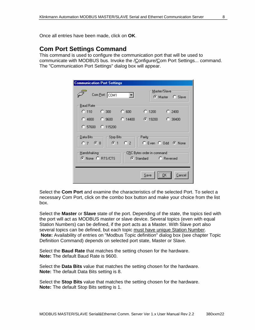
Com Port Settings Command This command is used to configure the communication port that will be used to communicate with MODBUS bus. Invoke the /Configure/Com Port Settings... command. The "Communication Port Settings" dialog box will appear.
Select the Com Port and examine the characteristics of the selected Port. To select a necessary Com Port, click on the combo box button and make your choice from the list box. Select the Master or Slave state of the port. Depending of the state, the topics tied with the port will act as MODBUS master or slave device. Several topics (even with equal Station Numbers) can be defined, if the port acts as a Master. With Slave port also several topics can be defined, but each topic must have unique Station Number. Note: Availability of entries on "Modbus Topic definition" dialog box (see chapter Topic Definition Command) depends on selected port state, Master or Slave. Select the Baud Rate that matches the setting chosen for the hardware. Note: The default Baud Rate is 9600. Select the Data Bits value that matches the setting chosen for the hardware. Note: The default Data Bits setting is 8. Select the Stop Bits value that matches the setting chosen for the hardware. Note: The default Stop Bits setting is 1.
Klinkmann Automation MODBUS MASTER/SLAVE Serial and Ethernet Communication Server 9
MODBUS MASTER/SLAVE Serial&Ethernet Comm. Server Ver 1.x User Manual Rev 2.2 380xxm22
Select the Parity that matches the setting chosen for the hardware. Note: The default Parity is Even. Select the Flow Control mode (option Handshaking): None or Hardware. Note: The default is None. Select the CRC bytes order in request and response command: Standard (LOBYTE HIBYTE) or Reversed (HIBYTE LOBYTE) . Choose the CRC bytes order that the connected nodes support. The following are recommended communication parameters: Baud Rate - 9600, 8 Data Bits, 1 Stop Bit and Even Parity. If necessary, these parameters can be changed. The communication parameters entered here must match with settings of the MODBUS bus. Once communication parameters, select Save to save the configuration for the communication port. Once all entries have been made, click on OK.
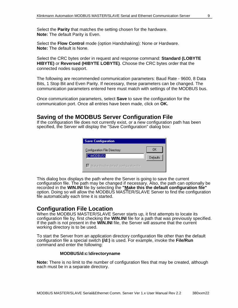
Saving of the MODBUS Server Configuration File If the configuration file does not currently exist, or a new configuration path has been specified, the Server will display the "Save Configuration" dialog box:
This dialog box displays the path where the Server is going to save the current configuration file. The path may be changed if necessary. Also, the path can optionally be recorded in the WIN.INI file by selecting the "Make this the default configuration file" option. Doing so will allow the MODBUS MASTER/SLAVE Server to find the configuration file automatically each time it is started.
Configuration File Location When the MODBUS MASTER/SLAVE Server starts up, it first attempts to locate its configuration file by, first checking the WIN.INI file for a path that was previously specified. If the path is not present in the WIN.INI file, the Server will assume that the current working directory is to be used. To start the Server from an application directory configuration file other than the default configuration file a special switch (/d:) is used. For example, invoke the File/Run command and enter the following: MODBUS/d:c:\directoryname Note: There is no limit to the number of configuration files that may be created, although each must be in a separate directory.
Klinkmann Automation MODBUS MASTER/SLAVE Serial and Ethernet Communication Server 10
MODBUS MASTER/SLAVE Serial&Ethernet Comm. Server Ver 1.x User Manual Rev 2.2 380xxm22
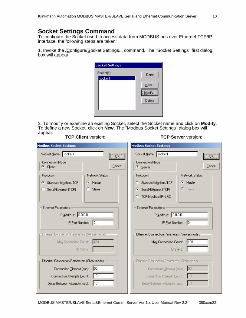
Socket Settings Command To configure the Socket used to access data from MODBUS bus over Ethernet TCP/IP interface, the following steps are taken: 1. Invoke the /Configure/Socket Settings... command. The "Socket Settings" first dialog box will appear:
2. To modify or examine an existing Socket, select the Socket name and click on Modify . To define a new Socket, click on New . The "Modbus Socket Settings" dialog box will appear:
TCP Client version: TCP Server version:
Klinkmann Automation MODBUS MASTER/SLAVE Serial and Ethernet Communication Server 11
MODBUS MASTER/SLAVE Serial&Ethernet Comm. Server Ver 1.x User Manual Rev 2.2 380xxm22
Enter the Socket Name . Connection Mode Two Connection Modes (Modbus Server behavior modes while establishing Ethernet Client-Server connection) are available: - Client mode (“Client Socket”) – Modbus server acts as a TCP Client and connects to remote IP address (to TCP Server). After connection Modbus Server acts as a Modbus Master or Slave depending on selected Network Status setting. - Server mode (“Server Socket”) – Modbus server acts as TCP Server and waits for connection from device (from TCP Client). After connection Modbus Server acts as Modbus Master or Slave depending on selected Network Status settings.
Network Status
Two Network Status modes (Server behavior in the Modbus network during Ethernet communication) are available: - Master status – Modbus Server acts as a Modbus Master (polls data from remote device); - Slave status – Modbus Server acts as a Modbus Slave (waits for read or write Modbus commands from remote Modbus Master and replies with corresponding Modbus protocol responses). Notes: 1. Several topics can be defined for Serial Communication Port with “Master” status. Several topics (all with equal IP Address and IP Port number) can be defined for Socket with “Master” status. For Serial Communication Port with “Slave” status also several topics can be defined, but each topic must have unique PLC Station Number. For Socket with “Slave” status also several topics (all with equal IP Port number and computer IP Address) can be defined, but each topic must have unique PLC Station Number. 2. Availability of entries in "Modbus Topic definition" dialog box (see the “Topic Definition Command” section later in this manual) depends on selected Socket “Connection Mode” (Client or Server) and “Network Status”(Master or Slave). Protocols The following Protocols are supported: - Standard Modbus/TCP protocol, in case communicating directly with device supporting Modbus TCP protocol, without CRC (Cyclical Redundancy Checksum) included; - Serial/Ethernet (TCP) protocol, in case serial device is accessed via serial/TCP Ethernet converter or GPRS-modem; in this option the 6-bytes header is not included in TCP/IP packet (CRC is included), it is suitable for GPRS communication by using serial/TCP direct conversion at serial device side; - TCP Modbus/IP + CRC protocol, in case serial device is accessed via GPRS-modem (or serial/TCP Ethernet converter) with embedded application running on it; in this option both the 6-bytes header and CRC are included in TCP/IP packet. The Serial/Ethernet (TCP) protocol (if used with Modbus Server TCP Server version) and specially the TCP Modbus/IP + CRC protocol are suitable for GPRS communication by using Klinkmann GPRS application running on GPRS-modem at serial device side. Important Note! It is highly recommended do not use more than 64 Sockets (TCP connections) in case using Modbus Server TCP Server version for GPRS communications.
Klinkmann Automation MODBUS MASTER/SLAVE Serial and Ethernet Communication Server 12
MODBUS MASTER/SLAVE Serial&Ethernet Comm. Server Ver 1.x User Manual Rev 2.2 380xxm22
Ethernet Parameters Enter the Local IP Address and Local Port Number of your computer. As Local IP Address the default IP address 0.0.0.0 or 128.0.0.1 can be entered. For “Client Socket” the Local Port Number can be: 0 (recommended, in this case Modbus Server can use any Port currently accessible on your PC) or non-zero (in this case Modbus Server either will use this configured Port, or if configured Port is not accessible then will not communicate at all); it is highly recommended to use IP Port number 0 for “Client Socket” – see “Important!” note below. For “Server Socket” enter non-zero Local Port Number . Important! If non-zero IP Port number is entered for “Client Socket “, then there will be Ethernet connection pauses each time, when DDE, SuiteLink or OPC connection is reinitialized by client application. Pauses happens because of each connection will stay in the TIME_WAIT state, when being closed. The default length of time that a connection will stay is 240 seconds. Length can be modified in Windows registry. Valid range depends on Windows: for Windows NT it is mentioned as 30-300 seconds, with Windows XP minimal value is 12 seconds. To modify the TIME_WAIT state time - do the following steps (at your own risk):
• Run Registry Editor (REGEDT32.EXE). • From the HKEY_LOCAL_MACHINE subtree, go to the following key: • \SYSTEM\CurrentControlSet\Services\Tcpip\Parameters. • Add a new value to Parameters key. (Right-click on Parameters key and select
New->DWORD value in context menu.) New entry’s name must be TcpTimedWaitDelay, value – TIME_WAIT state time (in seconds), e.g., 30.
• Exit the Registry Editor. • Reboot the system to make the changes take effect.
Note: As default, the TCP port number 502 is used for standard Modbus/TCP communication. Ethernet Connection Parameters (Client mode) These settings are available only for “Client Socket” to define the connection behavior: Connection Timeout Time interval (in seconds) the Modbus Server will try to establish connection with remote IP Address every connection attempt. Default value is 50 seconds. Connection Attempts Count The number of connection attempts. Default value is 100. Delay Between Attempts The time-out between connection attempts (in seconds). Default value is 10 seconds. Each time when DDE/SuiteLink/OPC client application activates the communication with some Modbus Server topic associated with “Client Socket”, the Modbus Server tries to establish Ethernet connection with remote Modbus device (PLC). If Modbus Server cannot establish the connection with remote IP address, then communication status of associated topic(s) will be changed to “bad” and Modbus Server reinitializes the Socket.
Klinkmann Automation MODBUS MASTER/SLAVE Serial and Ethernet Communication Server 13
MODBUS MASTER/SLAVE Serial&Ethernet Comm. Server Ver 1.x User Manual Rev 2.2 380xxm22
After that Modbus Server continues the connection attempts until connection is established or DDE/SuiteLink/OPC client application deactivates the communication. Ethernet Connection Parameters (Server mode) These settings are available only for “Server Socket” to define the connection behavior: Max. Connection Count This setting specifies the number of Ethernet connections supported by Socket, the default value is 100. Each time when DDE/SuiteLink/OPC client application activates the communication with some Modbus Server topic associated with “Master Socket”, the Modbus Server creates a Socket and waits for Ethernet connection from remote device (PLC). Modbus Server accepts the received connection if remote device (PLC) IP Address and Port corresponds to settings of one of topics associated with current “Server Socket”. ID String This setting is available only if “Protocol” type Serial/Ethernet (TCP) is selected and it is used to enter the contents of string, which must be sent as a first data from remote device (PLC) to Modbus Server and is used by Modbus Server to identify which of remote devices (PLCs) is connecting (considering that IP Address and IP Port of remote device (PLC) can be unknown – for example, if connecting via public GPRS network). This string can contain up to 11 ASCII characters. Recommended practice would be to include the remote device (PLC) Station Number here, for example, if PLC Station Number is 1 then in ID String value can be #1. Each time when DDE/SuiteLink/OPC client application activates communication with some Modbus Server topic associated with “Master Socket”, the “Protocol” type “Serial/Ethernet (TCP)” is selected and “ID String” is not empty, then Modbus Server creates a Socket and waits for Ethernet connection from remote device (PLC). After “ID String” is received from remote device (PLC), Modbus Server accepts connection and communication between Modbus Server and remote device (PLC) can start. Note: The “ID String” can be used only with devices/connections supporting possibilities to send non-Modbus data, for example, if some programmable GPRS-modem (e.g. Cinterion TC65T or Telit GT863-PY) is connected to remote device (PLC). Once all entries have been made, click on OK to process the configuration for the Socket. The "Socket Settings" dialog box will appear again. Click on Done when configuration for all Sockets has been performed. Note: If this is the first time either Communication Port or Socket have been configured, the user will be prompted to save configuration to an existing directory.
Topic Definition Command The user provides each MODBUS device with an arbitrary name that is used as the Topic Name for all references to this device. The following steps are taken to define the Topic attached to a device on MODBUS bus:
Klinkmann Automation MODBUS MASTER/SLAVE Serial and Ethernet Communication Server 14
MODBUS MASTER/SLAVE Serial&Ethernet Comm. Server Ver 1.x User Manual Rev 2.2 380xxm22
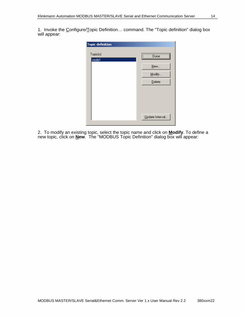
1. Invoke the Configure/Topic Definition… command. The "Topic definition" dialog box will appear:
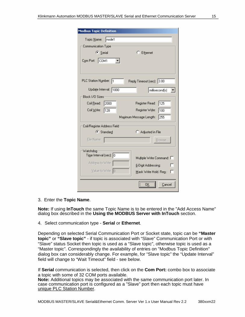
2. To modify an existing topic, select the topic name and click on Modify . To define a new topic, click on New . The "MODBUS Topic Definition" dialog box will appear:
Klinkmann Automation MODBUS MASTER/SLAVE Serial and Ethernet Communication Server 15
MODBUS MASTER/SLAVE Serial&Ethernet Comm. Server Ver 1.x User Manual Rev 2.2 380xxm22
3. Enter the Topic Name . Note: If using InTouch the same Topic Name is to be entered in the "Add Access Name" dialog box described in the Using the MODBUS Server with InTouch section. 4. Select communication type - Serial or Ethernet . Depending on selected Serial Communication Port or Socket state, topic can be “Master topic” or “Slave topic” - if topic is associated with “Slave” Communication Port or with “Slave” status Socket then topic is used as a “Slave topic”, otherwise topic is used as a “Master topic”. Correspondingly the availability of entries on "Modbus Topic Definition" dialog box can considerably change. For example, for “Slave topic” the “Update Interval” field will change to “Wait Timeout” field - see below. If Serial communication is selected, then click on the Com Port: combo box to associate a topic with some of 32 COM ports available. Note: Additional topics may be associated with the same communication port later. In case communication port is configured as a ”Slave” port then each topic must have unique PLC Station Number.
Klinkmann Automation MODBUS MASTER/SLAVE Serial and Ethernet Communication Server 16
MODBUS MASTER/SLAVE Serial&Ethernet Comm. Server Ver 1.x User Manual Rev 2.2 380xxm22
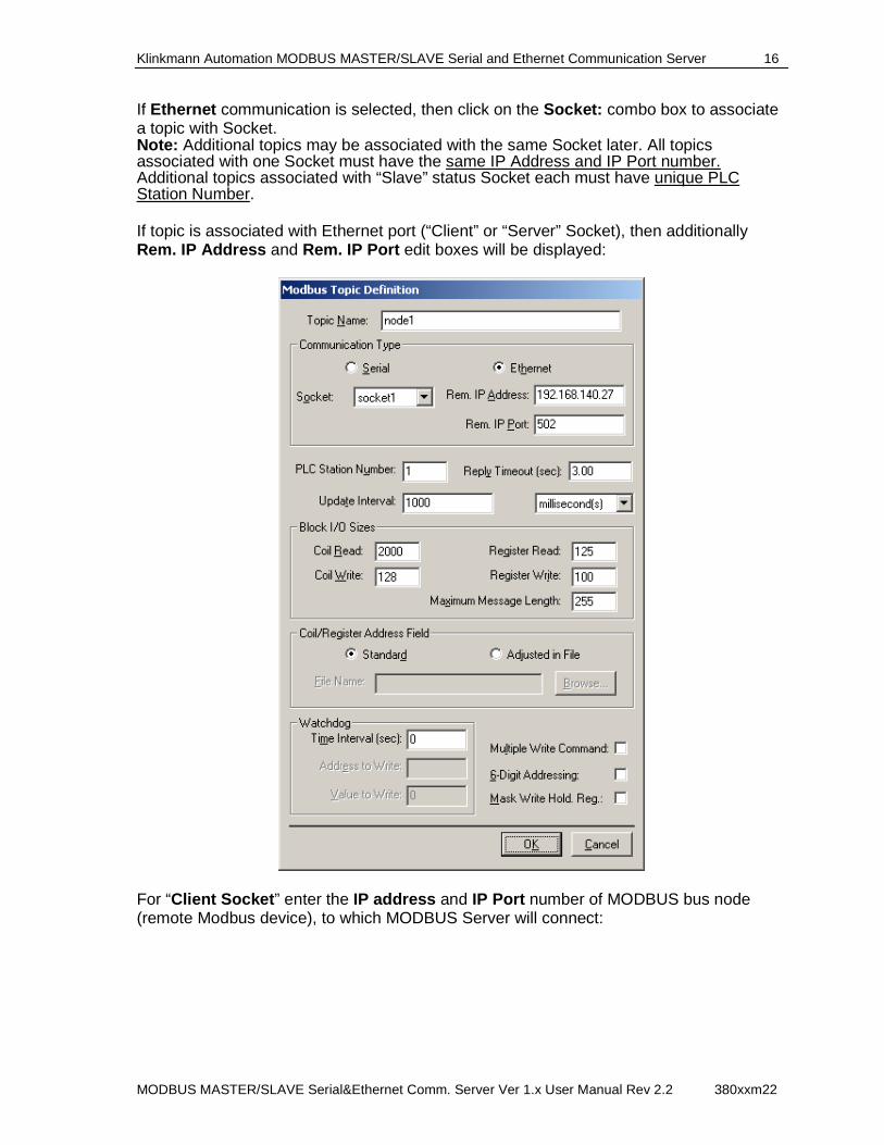
If Ethernet communication is selected, then click on the Socket: combo box to associate a topic with Socket. Note: Additional topics may be associated with the same Socket later. All topics associated with one Socket must have the same IP Address and IP Port number. Additional topics associated with “Slave” status Socket each must have unique PLC Station Number. If topic is associated with Ethernet port (“Client” or “Server” Socket), then additionally Rem. IP Address and Rem. IP Port edit boxes will be displayed:
For “Client Socket ” enter the IP address and IP Port number of MODBUS bus node (remote Modbus device), to which MODBUS Server will connect:
Klinkmann Automation MODBUS MASTER/SLAVE Serial and Ethernet Communication Server 17
MODBUS MASTER/SLAVE Serial&Ethernet Comm. Server Ver 1.x User Manual Rev 2.2 380xxm22
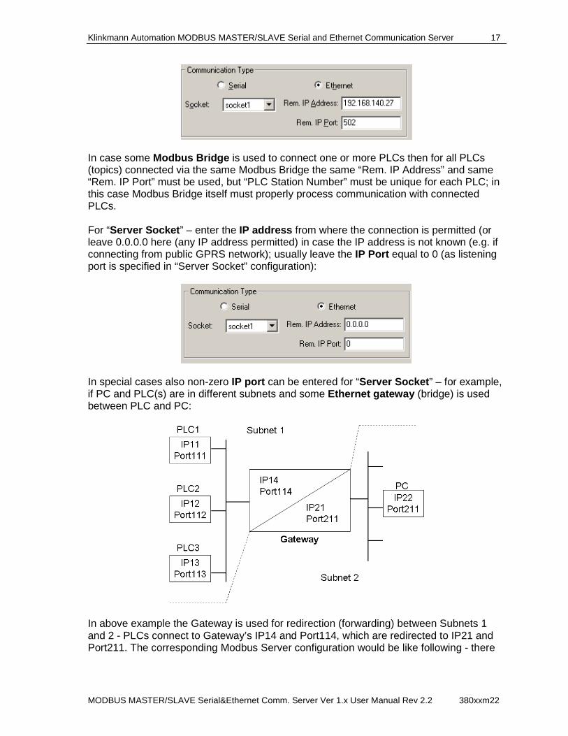
In case some Modbus Bridge is used to connect one or more PLCs then for all PLCs (topics) connected via the same Modbus Bridge the same “Rem. IP Address” and same “Rem. IP Port” must be used, but “PLC Station Number” must be unique for each PLC; in this case Modbus Bridge itself must properly process communication with connected PLCs. For “Server Socket ” – enter the IP address from where the connection is permitted (or leave 0.0.0.0 here (any IP address permitted) in case the IP address is not known (e.g. if connecting from public GPRS network); usually leave the IP Port equal to 0 (as listening port is specified in “Server Socket” configuration):
In special cases also non-zero IP port can be entered for “Server Socket ” – for example, if PC and PLC(s) are in different subnets and some Ethernet gateway (bridge) is used between PLC and PC:
In above example the Gateway is used for redirection (forwarding) between Subnets 1 and 2 - PLCs connect to Gateway’s IP14 and Port114, which are redirected to IP21 and Port211. The corresponding Modbus Server configuration would be like following - there
Klinkmann Automation MODBUS MASTER/SLAVE Serial and Ethernet Communication Server 18
MODBUS MASTER/SLAVE Serial&Ethernet Comm. Server Ver 1.x User Manual Rev 2.2 380xxm22
are non-zero IP Port numbers entered in Topic definition to be able to determine the exact PLC: “Server Socket” settings: Local IP Address: 0.0.0.0 Local Port Number: Port211 Topic “PLC1” settings: Rem. IP Address: IP21 Rem. Port Number: Port111 Topic “PLC2” settings: Rem. IP Address: IP21 Rem. Port Number: Port112 Topic “PLC3” settings: Rem. IP Address: IP21 Rem. Port Number: Port113
5. Enter the PLC (PC) Station number – the PLC (remote Modbus device) number on
the MODBUS bus for “Master topic” or the node number of “Slave topic” itself. 6. Enter the Reply Timeout (for “Master topic” only) - amount of time (in seconds) the
slave PLC (device) using the selected port will be given to reply to commands from the Modbus Server.
7. Enter the Update Interval field for “Master topic” or Wait Timeout for “Slave topic”. For “Master topic” the Update Interval field indicates the frequency the items/points on this topic will be read (polled). This is requested update rate - at this frequency the values of all this topic active items must be updated. In real conditions (when large amount of data is requested from device) the real update rate can be longer - the Modbus Server for maximum possible performance will automatically adjust it. For “Slave topic” the Wait Timeout field is used to enter the amount of time the “Slave topic” using the selected port or Socket and entered Station number will wait for any command arriving from Modbus Master – if no data arrive, then communication status will be changed to bad. Note: The default Update Interval is 1000 milliseconds. The Wait Timeout (for “Slave topic”) should be 5-10 times longer than expected polling rate of Modbus Master, otherwise bad communication status will be indicated time by time. If Wait Timeout is set to 0 (zero), then slave topic waits for data “forever” - the communication status will be good even if there is no communication with Modbus Master at all. The following entries can be entered only for “Master topic”: 8. Enter the maximum number of consecutive coils (contacts) to be read at time by one read command (Coil Read option). Valid values are between 0 and 2000. If Coil Read setting is set to zero, then this operation will not be available for selected Topic.
Klinkmann Automation MODBUS MASTER/SLAVE Serial and Ethernet Communication Server 19
MODBUS MASTER/SLAVE Serial&Ethernet Comm. Server Ver 1.x User Manual Rev 2.2 380xxm22
9. Enter the maximum number of consecutive coils that can be written at time by one write command (Coil Write option). Valid values can be between 0 and 128. If Coil Write setting is set to zero, then this operation will not be available for selected Topic. This option is not relevant in case Multiple Write Command is selected. Note: To process multiple coils writing in one command - the WIN.INI entry MultiWrite (see chapter WIN.INI entries) must be equal to 1 or 2 and Coil Write option for corresponding Topic must be configured in "MODBUS Topic Definition" dialog box greater than 1. If Coil Write option is equal to 1 then multiple coils writing for corresponding Topic is not processed despite of WIN.INI entry MultiWrite value.
10. Enter the maximum number of consecutive registers to be read at time by one read command (Register Read option). Valid values are between 0 and 125. If Register Read setting is set to zero, then this operation will not be available for selected Topic. 11. Enter the maximum number of consecutive registers that can be written at time by one write command (Register Write option). Valid values can be between 0 and 100. If Register Write settiing is set to zero, then this operation wil not be available for selected Topic. This option is not relevant in case Multiple Write Command is selected. Note: To process multiple registers writing in one command, the WIN.INI entry MultiWrite (see chapter WIN.INI entries) must be equal to 1 or 2 and Register Write option for corresponding Topic must be configured in "MODBUS Topic Definition" dialog box greater than 1. If Register Write option is equal to 1 then multiple registers writing for corresponding Topic is not processed despite of WIN.INI entry MultiWrite value. Note: The default Coil Read, Coil Write, Register Read and Register Write settings are optimal from Modbus Server performance point of view. Reduce these default settings only if you suppose that number of data to be processed in one request is too great and the PLC (remote Modbus device) cannot process such data quantity in satisfactory speed. 12. The Maximum Message Length value affects the Modbus communication similar way as Coil Read, Coil Write, Register Read and/or Register Write settings. If Coil Read, Coil Write, Register Read and/or Register Write values conflicts with Maximum Message Length setting then Modbus Server creates communication commands taking into account the greatest restriction. The default value is 255 bytes. 13. Select the accessible Coil/Register Address Field of your PLC (remote Modbus device). If Standard option is selected then Modbus Server validates the following addresses: Coils from 00001 to 09999, Contacts from 10001 to 19999, Input Registers from 30001 to 39999 and Output Registers from 40001 to 49999. If your PLC supports limited Address field (some Coils, Contacts or Registers are not accessible) then there may be some communication problems when Server tries to poll inaccessible memory areas. To avoid this problem, the valid Addresses can be presented in an ASCII file. Such file can be created and altered manually with any text editor (do not use a program that formats text, such as MS Word or Write unless the file is saved as a DOS text). Give the name to file that you like, e.g. "AddrFile".
Klinkmann Automation MODBUS MASTER/SLAVE Serial and Ethernet Communication Server 20
MODBUS MASTER/SLAVE Serial&Ethernet Comm. Server Ver 1.x User Manual Rev 2.2 380xxm22
If such file is created, then select Adjusted in File option. Now the File Name dialog option is accessible. Type the path and name of Address file, e.g. "C:\Modbus\ AddrFile". (You can also press the "Browse File" button. In this case the "Select file" dialog appears. Select your Address file and press "Open" button.) If Address file name is entered then the Server validates only Addresses presented in the file when process current Topic. The following is an example of Address file:
1,3,8-107,30002-30076,40004, 40023, 40097-40200
This example file informs that PLC supports Coils with Addresses 00001, 00003 and all Coils from 00008 to 00107. PLC does not support any Contact. Valid Input registers are from 30002 to 30076. Valid Output registers are 40004, 40023 as well as all registers from 40097 to 40200. Note: Valid Addresses must be presented in Address file in the following way. Coils are presented the first, then follows Contacts, then - Input Registers, and then - Output Registers. Items for monitor and control the communication with MODBUS node (see chapter Monitoring and Controlling Communication with MODBUS Bus) are not presented in Address file. Valid Addresses in file are presented as comma-separated individual digits (Addresses) and/or groups of Addresses. Each group of valid Addresses must be presented like the following example: 3-57 (here Coils from 00003 to 00057 are valid, Coils 00002 and 00058 should be invalid). Lower Address in file cannot follow after greater Address. It is not recommended to present a group of consecutive valid Addresses as comma-separated individual Addresses. For example, enter "2-4" instead of "2,3,4". Note: Unique Address file can be created for each Topic. At the same time common Address file can be used for all Topics. Note: Address file can be created for each Topic. At the same time common Address file can be used for all Topics. 14. Configure the Watchdog if PLC user program needs to check, whether there is communication with a computer (running Modbus Server and application) or not. With Watchdog activated the Server periodically writes some predefined value (e.g. 999) into predefined address in PLC’s memory (e.g. into 40100). At the same time the PLC program must periodically check the value in this memory address. If value is equal to Watchdog’s predefined value, then PLC’s program considers communication Status as Good and resets test address to different (non-predefined) value, e.g. to 0. (It will allow to program to check communication state the next time.) If value differs from predefined, then PLC’s program considers communication Status as Bad. Note: Because of time synchronizing problems with PLC and PC it is recommended to consider the communication Status as Bad only after few consecutive test value mismatch cases, not immediately after the first mismatch. To activate the Watchdog processing - set Watchdog Time Interval to non-zero value. Value entered in this field indicates the frequency the Server forwards Watchdog message to corresponding PLC. This value must be equal to time interval the PLC program checks the test address. Enter Address to Write field to indicate address in PLCs memory that is used as Watchdog test address. Address to Write must be valid item/point name (see Item Names section.)
Klinkmann Automation MODBUS MASTER/SLAVE Serial and Ethernet Communication Server 21
MODBUS MASTER/SLAVE Serial&Ethernet Comm. Server Ver 1.x User Manual Rev 2.2 380xxm22
Note: Use only Output Register areas for Watchdog. Do not take addresses not presented on current PLC configuration. Do not take addresses, used in PLC’s program logic. Enter integer from 0 to 65535 into Value to Write field to set Watchdog predefined value. The same value PLC program expects to see in test area. Note: Default Watchdog state is “non-active”, it is, Watchdog Time Interval is equal to zero. 15. By checking (or un-checking) the Multiple Write Command checkbox, select the type of write commands supported for this Topic: multiple write commands (Modbus functions 15 and 16) if Multiple Write Command is checked or single write commands (Modbus functions 5 and 6) if Multiple Write Command is not checked. For Slave topic - both multiple and single write commands are supported. 16. By checking (or un-checking) the 6-Digit Addresing checkbox, select whether to use the 5-digits (default) or 6-digits for addressing the item names for connected Modbus device. 17. By checking (or un-checking) the Mask Write Hold. Reg. checkbox, select whether to use the Modbus Function 22 (0x16 in hex) “Mask Write Register” to set or clear individual bits in Holding Registers. This function is applicable for individual bits in registers, see Item Names section below in this manual. By using this function, the performance can be greatly increased in case there are many bit writes executed at time. If Mask Write Hold. Reg. is not selected, each bit in register write is executed in two steps: Modbus Server at first reads a register (16-bit word containing this bit) from device to get the current bit value, then Server puts the bit value into this 16-bit word and writes this 16-bit word back to device. Note! Before using the Mask Write to Holding Registers, check if connected Modbus device supports this function. Update Interval for Multiple Topics The MODBUS Server supports the possibility to enter the new Update Interval value for multiple Topics in a single operation. At first these multiple Topics must be selected in the "Topic Definition" dialog box by holding the CTRL key while clicking on the selected ones:

Klinkmann Automation MODBUS MASTER/SLAVE Serial and Ethernet Communication Server 22
MODBUS MASTER/SLAVE Serial&Ethernet Comm. Server Ver 1.x User Manual Rev 2.2 380xxm22
Then click on Update Interval… . The "UPDATE INTERVAL" dialog box will appear:
Enter the new value in the Update Interval field and select the appropriate time measuring units (milliseconds, seconds, minutes or hours):
Click on OK to change the Update Interval value for all selected Topics or click on Cancel . The "Topic Definition" dialog box will appear again. The Update Interval can be changed also at run-time (for each Topic separately, not for several ones at once) after Topic is activated by client application (see description of UPDATEINTERVAL item in chapter Monitoring and Controlling Communication with MODBUS Bus ). Select Done when configuration for all Topics has been performed.
Klinkmann Automation MODBUS MASTER/SLAVE Serial and Ethernet Communication Server 23
MODBUS MASTER/SLAVE Serial&Ethernet Comm. Server Ver 1.x User Manual Rev 2.2 380xxm22
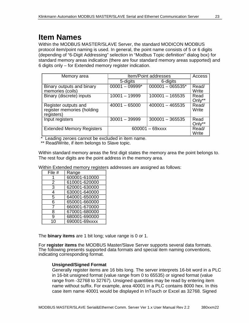
Item Names Within the MODBUS MASTER/SLAVE Server, the standard MODICON MODBUS protocol item/point naming is used. In general, the point name consists of 5 or 6 digits (depending of “6-Digit Addressing” selection in “Modbus Topic definition” dialog box) for standard memory areas indication (there are four standard memory areas supported) and 6 digits only – for Extended memory register indication.
Memory area Item/Point addresses Access 5-digits 6-digits
Binary outputs and binary memories (coils)
00001 – 09999* 000001 – 065535* Read/Write
Binary (discrete) inputs 10001 – 19999 100001 – 165535 Read Only**
Register outputs and register memories (holding registers)
40001 – 65000 400001 – 465535 Read/Write
Input registers 30001 – 39999 300001 – 365535 Read Only**
Extended Memory Registers
600001 – 69xxxx Read/Write
* Leading zeroes cannot be excluded in item name. ** Read/Write, if item belongs to Slave topic.
Within standard memory areas the first digit states the memory area the point belongs to. The rest four digits are the point address in the memory area. Within Extended memory registers addresses are assigned as follows:
File # Range 1 600001-610000 2 610001-620000 3 620001-630000 4 630001-640000 5 640001-650000 6 650001-660000 7 660001-670000 8 670001-680000 9 680001-690000 10 690001-69xxxx
The binary items are 1 bit long; value range is 0 or 1. For register items the MODBUS Master/Slave Server supports several data formats. The following presents supported data formats and special item naming conventions, indicating corresponding format.
Unsigned/Signed Format Generally register items are 16 bits long. The server interprets 16-bit word in a PLC in 16-bit unsigned format (value range from 0 to 65535) or signed format (value range from -32768 to 32767). Unsigned quantities may be read by entering item name without suffix. For example, area 40001 in a PLC contains 8000 hex. In this case item name 40001 would be displayed in InTouch or Excel as 32768. Signed
Klinkmann Automation MODBUS MASTER/SLAVE Serial and Ethernet Communication Server 24
MODBUS MASTER/SLAVE Serial&Ethernet Comm. Server Ver 1.x User Manual Rev 2.2 380xxm22
quantities may be read from the same channel by appending the suffix 'S' (or 's ') to the item name. So, item name 40001S would be displayed in InTouch or Excel as -32768. Long Format Two consecutive 16-bit words in a PLC can be interpreted as a 32-bit long integer (value range from -2,147,483,648 to 2,147,483,648). To read/write an item in signed long format - append the letter 'L ' (or 'l') to the item name. For example, if 40001 contains 1 and 40002 – contains 2, then 40001L returns 65538. Floating Point Format Two consecutive 16-bit words in a PLC can be interpreted as a floating point (real) value. For IEEE 32-bit floating point values (-3.402823 * 10+38 to 3.402823 * 10+38) the letter 'F' or 'f' must be appended to the item name. For example, if 40001 contains 9620 hex and 40002 - contains 2436 hex, then 40001F returns 3.959212 * 10-17. For floating point IEEE 754 standard, the letter 'R' or 'r ' must be appended to the item name.
Individual Bits in Register Individual bits in registers can be read as discrete tags by using the notation rrrr:b (or rrrr:bb or rrrr.b or rrrr.bb ), where rrrr specifies a valid input register, holding register or Extended memory register and b (or bb ) specifies a bit position between 1 and 16 (1 specifies the most significant bit of the register). Examples: 40001:1 most significant bit of first holding register 30008:16 least significant bit of an input register Write Only items In general, outputs (coils and holding registers) are Read/Write, but in some special cases it would be necessary to have Write Only possibility to same addresses. For this purpose the suffix 'W' (or 'w ') can be added to the item name, for example, 00001w or 400012LW.
VTQ-aware clients besides the value of the point can use also the time stamp and the quality of points. The quality value 0x00C0 indicates “good” quality. If Server cannot refresh the value of item, the item quality is set to “No Access” - 0x0004. Note: Do not operate with items representing non-de fined operands on the node! It will lead to communication failures.
Modbus Function 7 (Read Exception Status) Support Modbus function code 7 obtains the status (ON/OFF) of the eight internal coils, which addresses are controller dependent. User logic can program these coils to indicate slave status. The short length of response message allows the rapid reading of status. To use function code 7, the exception_status item (I/O integer) is created. Modbus Server creates additional separate message if exception_status item is active. This message is sent to PLC with Topic update interval.
Klinkmann Automation MODBUS MASTER/SLAVE Serial and Ethernet Communication Server 25
MODBUS MASTER/SLAVE Serial&Ethernet Comm. Server Ver 1.x User Manual Rev 2.2 380xxm22
Modbus Function 8 (Diagnostics) Support Modbus function code 8 provides a series of tests of checking the communication system between a client device (if using Modbus Server it is a Server itself) and a slave device (e.g. PLC). The following explains the item naming supported by Modbus Server to control Modbus function 8 processing. Important! Function 8 is supported only in serial communication and only with Master ports.
1. Sub-functions for PLC control The following sub-functions are supported:
00 (0 dec) - Return Query Data 01 (1 dec) - Restart Communications Option 04 (4 dec) - Force Listen Only Mode 0A (10 dec) - Clear Counters and Diagnostic Register 14 (20 dec) - Clear Overrun Counter and Flag
Important! The sub-function code in item/point names described below must be in decimal format, for example, DIAG10, not DIAG0A. To control the sub-function execution, three I/O items can be created in client application (e.g. InTouch) for each sub-function:
DIAGxx , I/O Discrete. Mandatory used. When application changes value from 0 to 1, then it causes execution of command with sub-code xx . To repeat the command execution – client application must set DIAGxx to 0, and then - again to 1. REZxx , I/O Discrete. Optionally used. Indicates the result of command with sub-code xx execution. If = 1 then it means the command with sub-code xx was executed successfully, and = 0 when no response from PLC received. DATAxx , I/O Integer. Optionally used. 2 bytes long value to be put into Data Field of request command - if data field value is relevant for sub-code. Relevant Data Field value is for sub-function 01 (Restart Communications Option, possible values 0 or 0xFF00).
For example, the processing of sub-function 01 (Restart Communications Option) with Communication Event Log to be cleared: Client application must activate items DIAG01, DATA01 and (optionally) REZ01 and do the following:
1. write value 0xFF00 into DATA01 item 2. write value 1 into discrete item DIAG01, 3. check, whether value of REZ01 changes from 0 to 1, and, if not changes, reset
DIAG01 to 0 and again to 1.
Klinkmann Automation MODBUS MASTER/SLAVE Serial and Ethernet Communication Server 26
MODBUS MASTER/SLAVE Serial&Ethernet Comm. Server Ver 1.x User Manual Rev 2.2 380xxm22
Note: Most of PLC control sub-functions can be controlled with only one item – DIAGxx . Using of REZxx item is optionally in all cases. With DATAxx the following principals are implemented in Server:
- if DATAxx data item is not created by application at all, then Server processes command with default Data Field value 0 (zero). - If DATAxx data item is created by application, then Server processes command with Data Field value, that application writes into DATAxx . If DATAxx is created, then Server never executes corresponding sub-function until value is assigned to DATAxx .
2. Sub-functions for reading diagnostic information from PLC The following sub-functions are supported:
02 (2 dec) - Return Diagnostic Register 0B (11 dec) - Return Bus Message Count 0C (12 dec) - Return Bus Communication Error Count 0D (13 dec) - Return Bus Exception Error Count 0E (14 dec) - Return Slave Message Count 0F (15 dec) - Return Slave No Response Count 10 (16 dec) - Return Slave NAK Count 11 (17 dec) - Return Slave Busy Count 12 (18 dec) - Return Bus Character Overrun Count
To control the execution of read sub-function - one I/O item is created in client application for each sub-function: DATAxx , I/O Integer. 2-bytes long value of Data Field from PLC response. xx – the code (in decimal format) of sub-function. To enable the Server processes the read command with sub-code xx, client application must activate the I/O item DATAxx. The corresponding command will be sent to PLC according to Topic update interval. To execute diagnostic reading at different update rate, a separate Topic must be created for all (or several) DATAxx I/O items. If separate Topic is used for diagnostics items – the communication Status item of Topic indicates the status of command 08 execution. For example, to get Diagnostic Register contents (sub-function 02) – create and poll the I/O item DATA02. The value of DATA02 will be the current contents of Diagnostic Register.
Notes on Data Processing in Slave Mode If topic is attached to the slave port or socket (“Slave” option selected in “Communication Port Settings” dialog box, see Com Port Settings Command section above in this manual or “Slave Network Status” option selected in “Modbus Socket Settings” dialog box, see Socket Settings Command section above in this manual), then this topic acts as a MODBUS slave device. It means, the Server does not poll data and does not transfer write commands to the PLC. The Server only waits for requests from master PLC and answers to these requests.
Klinkmann Automation MODBUS MASTER/SLAVE Serial and Ethernet Communication Server 27
MODBUS MASTER/SLAVE Serial&Ethernet Comm. Server Ver 1.x User Manual Rev 2.2 380xxm22
To provide data for master PLC, the client application must create and activate items for Modbus Server and assign initial values to items. Initial values may be assigned also by master PLC - by using write commands 05, 06, 15 or 16. In case master PLC requests data for items without initial values assigned by client application, the zero (0) value is provided to Master PLC. So, to get item’s value from MODBUS master node (PLC), the client application must activate an item and wait until MODBUS master node pokes corresponding value into Server. After that the Server forwards item’s value to the client application. To transfer (poke) item’s value into MODBUS master node, the client application must activate an item, poke value, and wait until MODBUS master node requests corresponding value from Server. If master PLC requests a group of Registers or Coils – then all requested Registers or Coils must present in Server’s active Item list. Otherwise the Server answers with error response message (error code 02 “Illegal Data address”). The “Multiple Write Command” option (see Topic Definition Command section above in this manual) is not relevant in Slave mode. In slave mode the Server accepts the following commands from master PLC : - Read Coils (function code 01), - Read Discrete Inputs (function code 02), - Read Holding Register (function code 03), - Read Input Register (function code 04), - Write Single Coil (function code 05), - Write Single Register (function code 06), - Write Multiple Coils (function code 15 (0x0F in hex)), - Write Multiple Registers (function code 16(0x10 in hex)). In slave mode Modbus Server recognizes the PLC address from the content of received request and compares it with “PLC Station Number” configured in the “MODBUS Topic Definition” dialog box (see Topic Definition Command section above in this manual). Each topic on the slave port must have unique PLC Station Number! Not all items for monitoring and controlling the communication with MODBUS node (chapter Monitoring and Controlling Communication with MODBU S Bus ) are relevant in slave mode.
Monitoring and Controlling Communication with MODBU S Bus For each master topic, there are the following additional items offered by MODBUS Communication Server to monitor and control the communication with MODBUS node. STATUS For each topic, there is a built-in discrete item that indicates the state of communication with MODBUS node. The discrete item (STATUS) is set to 0 when communication fails and set to 1 when communication is successful. From InTouch the state of communication may be read by defining an I/O Discrete tagname and associating it with the topic configured for the PLC and using STATUS as the item name.
Klinkmann Automation MODBUS MASTER/SLAVE Serial and Ethernet Communication Server 28
MODBUS MASTER/SLAVE Serial&Ethernet Comm. Server Ver 1.x User Manual Rev 2.2 380xxm22
From Excel , the status of the communication may be read by entering the following formula in a cell: =MODBUS|topic!STATUS UPDATEINTERVAL The UPDATEINTERVAL item is an Integer type Read/Write item used to access the currently set Update Interval (see Topic Definition Command). It indicates the current requested update interval (in milliseconds). The value of this item can be read through DDE or Suite Link. Client can poke new values to this item. The range of valid values is from 10 to 2147483647 milliseconds. The value of zero indicates that no items on this topic are updated. The write commands are still executed (new values written to PLC) if UPDATEINTERVAL value is 0. Note : By poking a value of zero to the UPDATEINTERVAL item, a client can stop all update activities on the corresponding topic without having to deactivate the items. MAXINTERVAL The MAXINTERVAL item is an Integer type Read Only item used to access the measured maximum update interval (in milliseconds) of all items for the corresponding topic for the last completed poll cycle. The range of valid values is from 0 to 2147483647 milliseconds. The UPDATEINTERVAL and MAXINTERVAL items can be used to tune the performance of communication. ITEMCOUNT The ITEMCOUNT item is an Integer type Read Only item used to access the number of active items in the corresponding topic. The range of valid values is from 0 to 2147483647. ERRORCOUNT The ERRORCOUNT item is an Integer type Read Only item used to access the number of active items with errors in the corresponding topic. The range of valid values is from 0 to 2147483647. ERRORITEMS The ERRORITEMS item is an Integer type Read/Write Only (unique for each topic) used to access the total number of items with invalid item names (these items are rejected by Server). The ERRORITEMS value can be reset by writing 0 to this item. The range of valid values is from 0 to 2147483647. WRITECOUNT The WRITECOUNT item is an Integer type Read Only item used to access the number of write commands (messages) waiting for execution. The range of valid values is from 0 to 2147483647. For example, in following way the WRITECOUNT item can be used to avoid the increasing of memory occupied by not executed write commands: - activate the hot link with WRITECOUNT item and start to monitor it;
Klinkmann Automation MODBUS MASTER/SLAVE Serial and Ethernet Communication Server 29
MODBUS MASTER/SLAVE Serial&Ethernet Comm. Server Ver 1.x User Manual Rev 2.2 380xxm22
- activate new write command (by poking new value) only if value of WRITECOUNT becomes equal to 0, e.g. all previous write commands are executed and memory occupied by them is freed. SUSPEND Special Read/Write Discrete Item SUSPEND may be used to control the communication with a separate topic. If application changes SUSPEND value from 0 to 1 then communication with topic is suspended. If SUSPEND value is changed back to 0 then communication with this topic is resumed. Note : If topic is suspended by setting SUSPEND value to 1, then Server rejects all new write values to this topic, i.e. no new write messages are created after SUSPEND value has changed from 0 to 1. Note: The slave topics validate these additional items, yet, a lot of items are not useful for slave communication control as well as for communication process monitoring. E.g., using of item SUSPEND takes no effect to communication because of it is not reasonable to interrupt communication with master node. The same, item’s MAXINTERVAL value can not characterize Server’s execution because of Server can only wait for data from master node.
Using the MODBUS Server with OPC Clients The "OPC & DDE" version of MODBUS Server is accessible from OPC Clients. There are the following general steps needed to access an OPC item from MODBUS Server: 1. Run OPC Client application and select the "MODBUS OPC and DDE Server" from
the list of available OPC Servers. If MODBUS Server currently is not running, it will start automatically.
2. Create a new group (or topic if Wonderware OPCLink application is used). 3. If OPC Client supports the validating of items, validate the item before adding it. 4. Add the item. Depending on OPC Client it can be done in several different ways, for
example: a) By entering separately the access path to topic name (valid topic name configured
in MODBUS Topic definition) and separately the item name. b) By entering the full path to item name in the format TopicName.ItemName where TopicName is the valid topic name configured in MODBUS Topic definition. c) By browsing the server address space.
By default the MODBUS Server is installed and used as a local OPC Server - both OPC Server and OPC Client reside on same computer. The MODBUS Server can run also as a remote OPC Server – in this case OPC Server and OPC Client are located on separate computers. Accessing the remote OPC Server is same as for local OPC Server, but some DCOM (Distributed COM) configuration is required before accessing the remote OPC Server. The DCOM configuration must be done both on OPC Server and OPC Client computers.
Klinkmann Automation MODBUS MASTER/SLAVE Serial and Ethernet Communication Server 30
MODBUS MASTER/SLAVE Serial&Ethernet Comm. Server Ver 1.x User Manual Rev 2.2 380xxm22
Configuring DCOM After MODBUS Server "OPC & DDE" version installation, the System Administrator must configure DCOM by DCOM configuration program - by Dcomcnfg.exe (or Dcomcnfg32.exe for Win9x) system tool. This utility is located in the Windows system directory - e.g. in \WinNT\system32\ or \Win9x\system\. After starting Dcomcnfg.exe, select MODBUS OPC & DDE Server on Applications page and click on Properties - the “MODBUS OPC & DDE Server Properties” window will appear. All further configuration is to be done from there. Configuring DCOM to access MODBUS Server as a local OPC Server To access MODBUS OPC & DDE Server as a local OPC server: Authentication level can be any of: (None) Call Connect Default Packet Packet Integrity Packet Privacy Location “Run application on this computer” must be checked. Security/access permissions - default access permissions can be used in case using MODBUS OPC & DDE Server as local OPC server. If it is necessary to access MODBUS OPC & DDE Server from local OPC Clients configured as services , then Allow Access permission must be configured for SYSTEM and for all users, which need access to the MODBUS OPC & DDE Server. Security/launch permissions - Allow Launch must be specified for each user, which launches OPC Client on local machine. Typically specify Allow Launch for “Users” group. If is necessary to access MODBUS OPC & DDE Server from local OPC Clients configured as Services then Allow Launch permission must be configured for SYSTEM also. Security/configuration permissions Administrators - Full Control CREATOR OWNER - Full Control SYSTEM - Full Control Full Control for all users, which have permission to register MODBUS OPC & DDE Server as OPC server. For users, which have permission to read data from OPC server the sufficient permission is Read. Note - OPC server registration and unregistration is silent. No error messages are displayed if operation is unavailable due to permission restrictions.
Klinkmann Automation MODBUS MASTER/SLAVE Serial and Ethernet Communication Server 31
MODBUS MASTER/SLAVE Serial&Ethernet Comm. Server Ver 1.x User Manual Rev 2.2 380xxm22
Identify Identify has to be The launching user . In case of using MODBUS OPC & DDE Server as local OPC server, the Identify can be also The interactive user , but this setting will not work if user is not logged on and OPC Clients which are running as Services will not be able to connect to MODBUS OPC & DDE Server while user is not logged on computer. Also This user can be selected. In this case MODBUS OPC & DDE Server will be invisible on the screen and MODBUS OPC & DDE Server user interface will be inaccessible. If user is different as user logged on then MODBUS OPC & DDE Server cannot be terminated by Task Manager. The user specified in this setting can be any user which have access to hardware and software resources used by MODBUS OPC & DDE Server. This user can be without permission to launch or configure MODBUS OPC & DDE Server specified in the Security page of DCOM configuration program. Configuring DCOM to access MODBUS Server as a remote OPC Server To access MODBUS OPC & DDE Server as a remote OPC server (form remote computer) and to browse available OPC Servers, at first you have to configure DCOM settings for OPCEnum.exe both on server and client computers. The OPCEnum.exe, opccomn_ps.dll and OPCProxy.dll must be installed and registered on both - server and client computers and MODBUS OPC & DDE Server must be installed and registered on computer where it will run. For some OPC clients it may be necessary to register MODBUS OPC & DDE Server on client computer. OPCEnum OPCEnum is used to browse OPC servers on local or remote computer the DCOM settings for OPCEnum.exe are following: Location “Run application on this computer” - must be checked on both computers. Security/access permissions can be default. Security/launch permissions Launch permission must be set for each user, which can be able to configure OPC items on OPC Server computer. On the client computer OPCEnum launch permissions can be default, but some OPC clients may handle this situation incorrectly, therefore it is better to assign launch permission for users working on remote OPC client computer. Security/configuration permissions SYSTEM must have at least Read permission on OPC Server computer. On OPC Client computers at least Read permission must be set for users working with OPC clients. Administrators must have Full Control permission on both computers, otherwise nobody can be able to configure or unregister OPCEnum. Identify On GSM-Control OPC Server computer the Identify must be set to The interactive User . On remote OPC Client computer it can be The interactive user or The launching user .
Klinkmann Automation MODBUS MASTER/SLAVE Serial and Ethernet Communication Server 32
MODBUS MASTER/SLAVE Serial&Ethernet Comm. Server Ver 1.x User Manual Rev 2.2 380xxm22
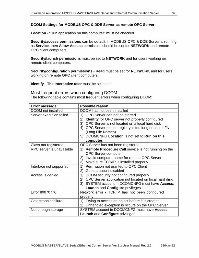
DCOM Settings for MODBUS OPC & DDE Server as remote OPC Server: Location - “Run application on this computer” must be checked. Security/access permissions can be default. If MODBUS OPC & DDE Server is running as Service , then Allow Access permission should be set for NETWORK and remote OPC client computers. Security/launch permissions must be set to NETWORK and for users working on remote client computers. Security/configuration permissions - Read must be set for NETWORK and for users working on remote OPC client computers. Identify - The interactive user must be selected. Most frequent errors when configuring DCOM The following table contains most frequent errors when configuring DCOM: Error message Possible reason DCOM not installed DCOM has not been installed Server execution failed 1) OPC Server can not be started
2) Identity for OPC server not properly configured 3) OPC Server is not located on a local hard disk 4) OPC Server path in registry is too long or uses LFN
(Long File Names) 5) DCOMCNFG Location is not set to Run on this
computer . Class not registered OPC Server has not been registered RPC server is unavailable 1) Remote Procedure Call service is not running on the
OPC Server computer 2) Invalid computer name for remote OPC Server 3) Make sure TCP/IP is installed properly
Interface not supported 1) Permission not granted to OPC Client 2) Guest account disabled
Access is denied 1) DCOM security not configured properly 2) OPC Server application not located on local hard disk 3) SYSTEM account in DCOMCNFG must have Access ,
Launch and Configure privileges Error 80070776 Network error - TCP/IP has not been configured
properly Catastrophic failure 1) Trying to access an object before it is created
2) Unhandled exception is occurs on the OPC Server Not enough storage SYSTEM account in DCOMCNFG must have Access ,
Launch and Configure privileges
Klinkmann Automation MODBUS MASTER/SLAVE Serial and Ethernet Communication Server 33
MODBUS MASTER/SLAVE Serial&Ethernet Comm. Server Ver 1.x User Manual Rev 2.2 380xxm22
Running MODBUS "OPC & DDE" version as Windows NT Service To install MODBUS Server "OPC & DDE" version to run as Windows NT Service , the MODBUS Server must be started with command line parameter "/Service": MODBUS /Service After this the "MODBUS OPC & DDE Server" NT Service will be installed with Startup type "Manual". The Service Startup configuration can be changed by MS Windows NT Control Panel/Services configuration dialog boxes. The Allow Service to Interact with Desktop checkbox in "Service" dialog box must be checked (the "Service" dialog box can be invoked by pressing the "Startup" button on "Services" dialog box when Service MODBUS OPC & DDE Server is selected). If Allow Service to Interact with Desktop is not selected then MODBUS Server full functionality is not ensured (e.g. the Server configuration can not be changed, no message boxes will be displayed, etc.). To use MODBUS Server "OPC & DDE" version as Windows NT Service you may need to configure DCOM. For details of configuring DCOM refer to Configuring DCOM section of this manual. If "MODBUS OPC & DDE Server" NT Service will be accessed only from local OPC clients (i.e. MODBUS Server will not be used as a remote OPC Server), then custom access and launch permissions "NETWORK" are not needed. To uninstall "MODBUS OPC & DDE Server" NT Service, at first the Service must be stopped by Control Panel/Services/Stop and then MODBUS Server must be started manually with command line parameter "/DelService": MODBUS /DelService After this the MODBUS Server "OPC & DDE" version will be still registered and accessible to OPC clients.
Using MODBUS with OPCLink Server The Wonderware OPCLink I/O Server (hereafter referred to as "OPCLink") is a Microsoft Windows application program that acts as a communication protocol converter and allows other Windows application programs access to data from local or remote OPC servers. OPCLink connects to OPC servers, converts client commands to OPC protocol and transfers data back to clients using DDE, FastDDE, or Suite Link protocols.
Please refer to Wonderware OPCLink Server and OPC Browser User’s Gu ide for details how to install, start and use the OPCLink Server. The following information in this section covers only the most important points about using "OPC & DDE" version of MODBUS Server with OPCLink Server. OPCLink Topic Definition The Topic Definition option from OPC Link Configure menu is used to create, modify, or delete OPCLink topic definitions. If OPC Link will communicate with MODBUS Server then there must be one or more topics defined for MODBUS Server. There are following important fields on the "OPCLink Topic Definition" dialog box:
Klinkmann Automation MODBUS MASTER/SLAVE Serial and Ethernet Communication Server 34
MODBUS MASTER/SLAVE Serial&Ethernet Comm. Server Ver 1.x User Manual Rev 2.2 380xxm22
Topic Name Enter a unique name (e.g. PLC1) for the PLC in this field. If using InTouch then same Topic Name is to be entered in the "Add Access Name" dialog box when defining the Access Names for OPCLink Server in InTouch WindowMaker. OPC Server Name Select the name of the OPC server (MODBUS.OPC_Server ) that will be used by this topic. The list box shows the registered OPC servers in the system. OPC Path Enter the name of the OPC path (e.g. node2. ) used by this topic. This OPC path is the first part of a full OPC item name string common to all items that will be used in this topic. The available OPC paths for MODBUS Server can be obtained by clicking on "Browse" button (this allows to view the MODBUS Server’s exposed address space). Update Interval Enter the frequency (in milliseconds) that the server will acquire data for the items/points associated with this topic. If 0 (zero) is entered here, OPCLink will not gather data from MODBUS Server. Browse Clicking on this button initiates the browsing through exposed address space of MODBUS Server. All currently available item/point names (including data area names and range of addresses) and names of pre-defined (additional) items will appear on "Browse OPC items:" window in alphabetical order. Accessing MODBUS Items via the OPCLink Server The communication protocol addresses an element of data in a conversation that uses a three-part naming convention that includes the application name , topic name and item name . The following briefly describes each portion of this naming convention: application name The name of the Windows program (server) that will be accessing the data element. In the case of data coming from or going to MODBUS Server "OPC & DDE" version, the application portion of the address is OPCLINK . topic name Meaningful names are configured to identify specific devices (PLCs). These names are then used as the topic name in all conversations to that device (PLC). This must be same name as Topic Name entered in the "OPCLink Topic Definition" dialog box, for example, PLC2. Note! You can define multiple topic names for the same PLC to poll different points at different rates. item name A specific data element within the specified topic. The OPCLink Server item syntax follows the following rules. The item names must start with:
d – discrete value
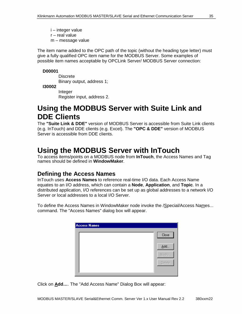
Klinkmann Automation MODBUS MASTER/SLAVE Serial and Ethernet Communication Server 35
MODBUS MASTER/SLAVE Serial&Ethernet Comm. Server Ver 1.x User Manual Rev 2.2 380xxm22
i – integer value r – real value m – message value
The item name added to the OPC path of the topic (without the heading type letter) must give a fully qualified OPC item name for the MODBUS Server. Some examples of possible item names acceptable by OPCLink Server/ MODBUS Server connection:
D00001 Discrete Binary output, address 1;
I30002 Integer Register input, address 2.
Using the MODBUS Server with Suite Link and DDE Clients The "Suite Link & DDE" version of MODBUS Server is accessible from Suite Link clients (e.g. InTouch) and DDE clients (e.g. Excel). The "OPC & DDE" version of MODBUS Server is accessible from DDE clients.
Using the MODBUS Server with InTouch To access items/points on a MODBUS node from InTouch , the Access Names and Tag names should be defined in WindowMaker .
Defining the Access Names InTouch uses Access Names to reference real-time I/O data. Each Access Name equates to an I/O address, which can contain a Node , Application , and Topic . In a distributed application, I/O references can be set up as global addresses to a network I/O Server or local addresses to a local I/O Server. To define the Access Names in WindowMaker node invoke the /Special/Access Names... command. The "Access Names" dialog box will appear.
Click on Add… . The "Add Access Name" Dialog Box will appear:
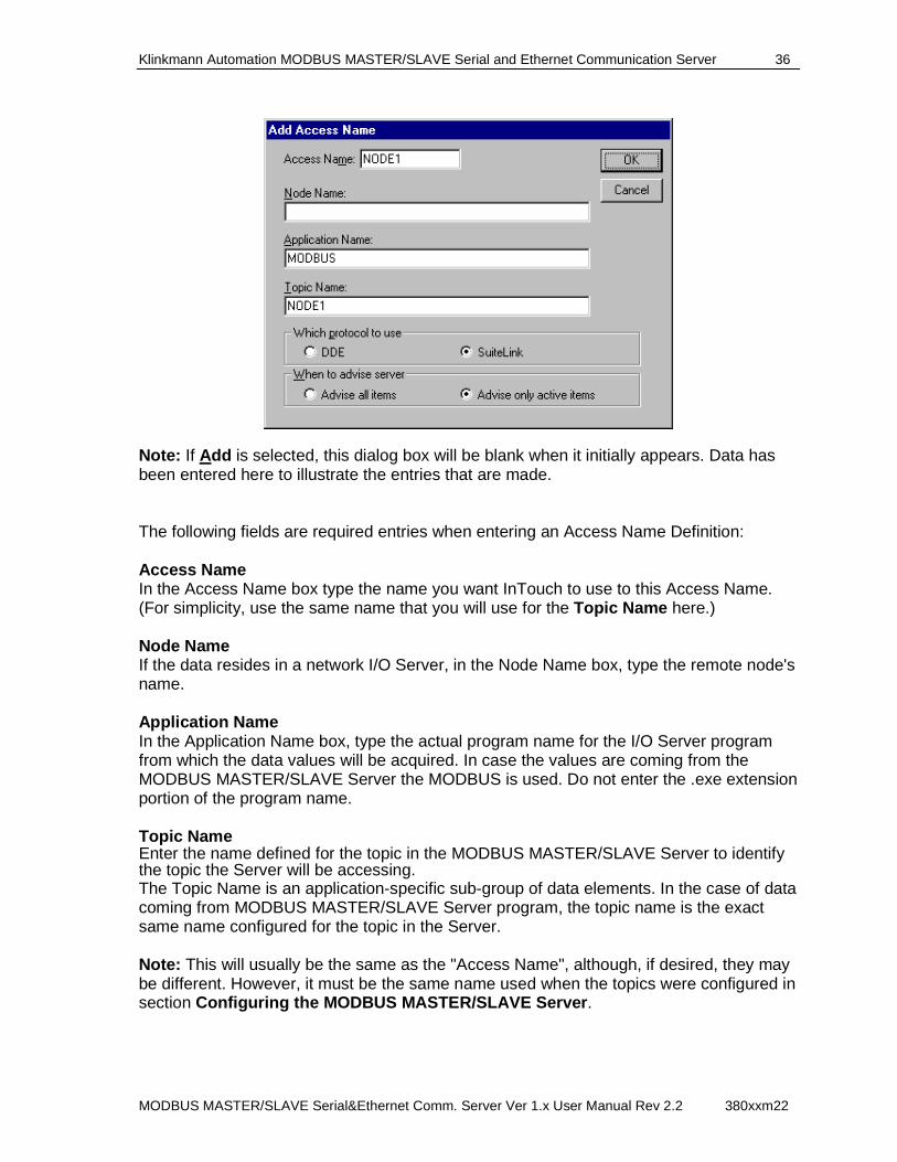
Klinkmann Automation MODBUS MASTER/SLAVE Serial and Ethernet Communication Server 36
MODBUS MASTER/SLAVE Serial&Ethernet Comm. Server Ver 1.x User Manual Rev 2.2 380xxm22
Note: If Add is selected, this dialog box will be blank when it initially appears. Data has been entered here to illustrate the entries that are made. The following fields are required entries when entering an Access Name Definition: Access Name In the Access Name box type the name you want InTouch to use to this Access Name. (For simplicity, use the same name that you will use for the Topic Name here.) Node Name If the data resides in a network I/O Server, in the Node Name box, type the remote node's name. Application Name In the Application Name box, type the actual program name for the I/O Server program from which the data values will be acquired. In case the values are coming from the MODBUS MASTER/SLAVE Server the MODBUS is used. Do not enter the .exe extension portion of the program name. Topic Name Enter the name defined for the topic in the MODBUS MASTER/SLAVE Server to identify the topic the Server will be accessing. The Topic Name is an application-specific sub-group of data elements. In the case of data coming from MODBUS MASTER/SLAVE Server program, the topic name is the exact same name configured for the topic in the Server. Note: This will usually be the same as the "Access Name", although, if desired, they may be different. However, it must be the same name used when the topics were configured in section Configuring the MODBUS MASTER/SLAVE Server .
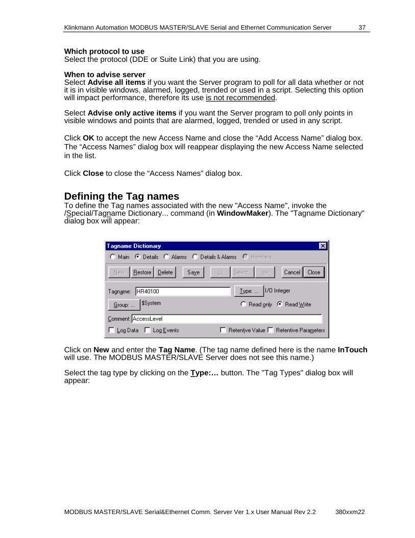
Klinkmann Automation MODBUS MASTER/SLAVE Serial and Ethernet Communication Server 37
MODBUS MASTER/SLAVE Serial&Ethernet Comm. Server Ver 1.x User Manual Rev 2.2 380xxm22
Which protocol to use Select the protocol (DDE or Suite Link) that you are using. When to advise server Select Advise all items if you want the Server program to poll for all data whether or not it is in visible windows, alarmed, logged, trended or used in a script. Selecting this option will impact performance, therefore its use is not recommended. Select Advise only active items if you want the Server program to poll only points in visible windows and points that are alarmed, logged, trended or used in any script. Click OK to accept the new Access Name and close the “Add Access Name” dialog box. The “Access Names” dialog box will reappear displaying the new Access Name selected in the list. Click Close to close the “Access Names” dialog box.
Defining the Tag names To define the Tag names associated with the new "Access Name", invoke the /Special/Tagname Dictionary... command (in WindowMaker ). The "Tagname Dictionary" dialog box will appear:
Click on New and enter the Tag Name . (The tag name defined here is the name InTouch will use. The MODBUS MASTER/SLAVE Server does not see this name.) Select the tag type by clicking on the Type:… button. The "Tag Types" dialog box will appear:
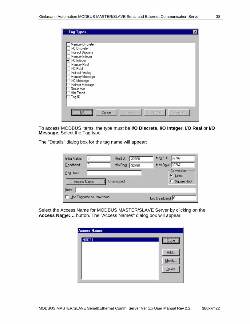
Klinkmann Automation MODBUS MASTER/SLAVE Serial and Ethernet Communication Server 38
MODBUS MASTER/SLAVE Serial&Ethernet Comm. Server Ver 1.x User Manual Rev 2.2 380xxm22
To access MODBUS items, the type must be I/O Discrete , I/O Integer , I/O Real or I/O Message . Select the Tag type. The "Details" dialog box for the tag name will appear:
Select the Access Name for MODBUS MASTER/SLAVE Server by clicking on the Access Name:… button. The "Access Names" dialog box will appear:
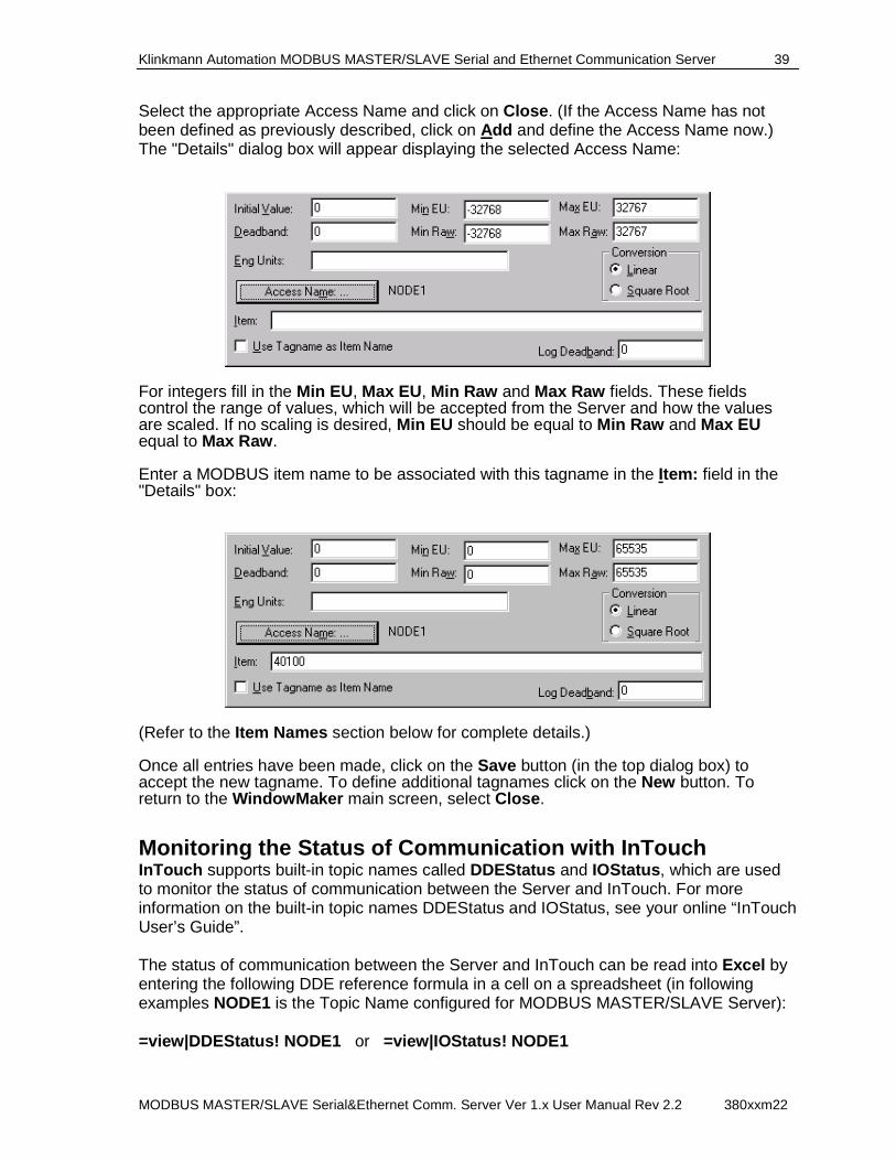
Klinkmann Automation MODBUS MASTER/SLAVE Serial and Ethernet Communication Server 39
MODBUS MASTER/SLAVE Serial&Ethernet Comm. Server Ver 1.x User Manual Rev 2.2 380xxm22
Select the appropriate Access Name and click on Close . (If the Access Name has not been defined as previously described, click on Add and define the Access Name now.) The "Details" dialog box will appear displaying the selected Access Name:
For integers fill in the Min EU , Max EU, Min Raw and Max Raw fields. These fields control the range of values, which will be accepted from the Server and how the values are scaled. If no scaling is desired, Min EU should be equal to Min Raw and Max EU equal to Max Raw . Enter a MODBUS item name to be associated with this tagname in the Item: field in the "Details" box:
(Refer to the Item Names section below for complete details.) Once all entries have been made, click on the Save button (in the top dialog box) to accept the new tagname. To define additional tagnames click on the New button. To return to the WindowMaker main screen, select Close .
Monitoring the Status of Communication with InTouch InTouch supports built-in topic names called DDEStatus and IOStatus , which are used to monitor the status of communication between the Server and InTouch. For more information on the built-in topic names DDEStatus and IOStatus, see your online “InTouch User’s Guide”. The status of communication between the Server and InTouch can be read into Excel by entering the following DDE reference formula in a cell on a spreadsheet (in following examples NODE1 is the Topic Name configured for MODBUS MASTER/SLAVE Server): =view|DDEStatus! NODE1 or =view|IOStatus! NODE1
Klinkmann Automation MODBUS MASTER/SLAVE Serial and Ethernet Communication Server 40
MODBUS MASTER/SLAVE Serial&Ethernet Comm. Server Ver 1.x User Manual Rev 2.2 380xxm22
Notes on Using Microsoft Excel Data from MODBUS MASTER/SLAVE topics (nodes) may be accessed from Excel spreadsheets. To do so, enter a formula like the following into a cell on the spreadsheet. =MODBUS|topic!item Sometimes, Excel requires the topic and/or item to be surrounded by apostrophes. In the formula, topic must be replaced with one of the valid topic names defined during the Server configuration process. Replace item with one of the valid item names described in the Item Names section.
Reading Values into Excel Spreadsheets Values may be read directly into Excel spreadsheets by entering a DDE formatted formula into a cell, as shown in the following examples: =MODBUS|'NODE1'!'40100' = MODBUS |'MODBUS'!'00033' = MODBUS |'node'!'30111' Note: Refer to the Microsoft Excel manual for complete details on entering Remote Reference formulas for cells.
Writing Values to MODBUS MASTER/SLAVE Points Values may be written to the Server from Microsoft Excel by creating an Excel macro that uses the POKE command. The proper command is entered in Excel as follows: channel=INITIATE("MODBUS","topicname") =POKE(channel,"itemname", Data_Reference) =TERMINATE (channel) =RETURN() The following describes each of the above POKE macro statements: channel=INITIATE("MODBUS","topicname") Opens a channel to a specific topic name (defined in the Server) in an application with name MODBUS (the executable name less the .EXE) and assigns the number of that opened channel to channel. Note: By using the channel=INITIATE statement the word channel must be used in the =POKE statement instead of the actual cell reference. The "applicationname" and "topicname" portions of the formula must be enclosed in quotation marks. =POKE(channel,"itemname", Data_Reference) POKEs the value contained in the Data_Reference to the specified item name (actual location in the MODBUS node) via the channel number returned by the previously executed INITIATE function. Data_Reference is the row/column ID of the cell containing the data value. For "itemname" , use some of the valid item names specified like described in the Item Names section.
Klinkmann Automation MODBUS MASTER/SLAVE Serial and Ethernet Communication Server 41
MODBUS MASTER/SLAVE Serial&Ethernet Comm. Server Ver 1.x User Manual Rev 2.2 380xxm22
=TERMINATE(channel) Closes the channel at the end of the macro. Some applications have a limited number of channels. Therefore they should be closed when finished. Channel is the channel number returned by the previously executed INITIATE function. =RETURN() Marks the end of the macro. The following is an example of Excel macro used to poke value from cell B2 to topic NODE1item 40100: PokeMacro -Ctrl a =INITIATE("MODBUS","NODE1") =POKE(A2,"40100",B2) =ON.TIME(NOW()+0.01,"TerminateDDEChannel") =RETURN() TerminateDDEChannel =TERMINATE(A2) =RETURN() Note: Refer to the Microsoft Excel manual for complete details on entering Remote Reference formulas for cells.
Klinkmann Automation MODBUS MASTER/SLAVE Serial and Ethernet Communication Server 42
MODBUS MASTER/SLAVE Serial&Ethernet Comm. Server Ver 1.x User Manual Rev 2.2 380xxm22
Troubleshooting WIN.INI entries The first time you run the MODBUS MASTER/SLAVE Server configuration, most of the items in the following list will automatically appear in the WIN.INI file, located in the MS Windows system directory (e.g. C:\WINNT or C:\Win95). It is an ASCII file and can be altered manually if you wish with any text editor, e.g., MS Windows Notepad (do not use a program that formats text, such as MS Word or Write unless the file is saved as a DOS text). The following is a typical entry for the MODBUS MASTER/SLAVE Server: [MODBUS] WinIconic=0 WinFullScreen=0 WinTop=112 WinLeft=0 WinWidth=200 WinHeight=168 There are following additional WIN.INI entries available for MODBUS MASTER/SLAVE Server: MultiWrite The MultiWrite entry is used to enter the data writing principles for the Server. The following values can be entered. (1) If MultiWrite=0 (default value) then for each new write value a separate write message is created. Only one write message is executed per scan. The values in the PLC are changed by the Server in the same sequence as they are changed in the user (client) application. In this case the data update rate is low if application changes values very frequently. (2) If MultiWrite=1 then the same message can be used for the writing of new values into the consecutive memory addresses for the same memory area (for example, into 40001, 40002, 40003...). Up to 128 consecutive values can be included in the same write command depending on configured Block I/O Sizes (Coil Write and Register Write) in the "MODBUS Topic Definition" dialog box (see chapter Topic Definition Command). The new value can be added only to the end of the last write message (last message in the list of pending write messages). Therefore some values may be written into the PLC memory simultaneously even if the client application changes them step-by-step. In this case the writing speed can be seriously increased. For example, the client application sequentially changes the values of following 100 items: 40001, 40002, ... , 40100 and the values of following 100 items: 00001, 00002, ... , 00100. In this case the Server creates only two write messages to write the new values for all the changed items. If the values of the same Items are changed in the following sequence: 40001, 00001, 40002, 00002, 40003, ... then Server creates a separate write message for the each new write value.
Klinkmann Automation MODBUS MASTER/SLAVE Serial and Ethernet Communication Server 43
MODBUS MASTER/SLAVE Serial&Ethernet Comm. Server Ver 1.x User Manual Rev 2.2 380xxm22
(3) If MultiWrite=2 then the Server tries to include the new write value into the some of previously created messages ignoring the sequence of data changing in the client application. Important! If MultiWrite=2 then maximum writing speed is achieved, but this option is not recommended if data changing sequence is important for PLC program! The MultiWrite entry is relevant only in case of Master Topic, when Write command type is configured as “Multiple Write Command” ("MODBUS Topic Definition" dialog box in chapter Topic Definition Command). SlowPollRetries and SlowPollInterval The SlowPollRetries entry is used to enter the number of consecutive error retries for one topic (Node). If after SlowPollRetries there is still no successful response from MODBUS node, then this topic is set to slow poll mode. The WIN.INI file SlowPollInterval entry is used to enter the slow poll mode update interval (in seconds). The default values (they are used if WIN.INI file does not contain these entries) are SlowPollRetries equal to 3 and SlowPollInterval equal to 60 seconds. For example, the following entries can be used to specify that slow poll mode 2 minutes will start after 5 consecutive unsuccessful retries: SlowPollRetries=5 SlowPollInterval=120 Entering the slow poll mode is reported to WWLogger by following string: "Set slow poll mode - poll after each <SlowPollInte rval * 1000> msecs. Stop error logging to Topic <TOPICNAME>." Leaving the slow poll mode is reported to WWLogger by following string: "Port <PORTNAME>; return to normal communication to Topic <TOPICNAME>." The WriteRetryIndefinitely entry is used to disable the deleting of pending write messages when slow poll mode is started. As default (no WriteRetryIndefinitely entry in WIN.INI or WriteRetryIndefinitely=0) all write messages for this topic are deleted when topic enters the slow poll mode. To disable this the following entry can be used: WriteRetryIndefinitely=1 Note! Be careful when using this setting if PLC is switched off but client application continues to generate new values to be written to this PLC - it can cause the computer memory overfill with memory allocated for write messages.

Klinkmann Automation MODBUS MASTER/SLAVE Serial and Ethernet Communication Server 44
MODBUS MASTER/SLAVE Serial&Ethernet Comm. Server Ver 1.x User Manual Rev 2.2 380xxm22
ConsecutiveWriteErrors The ConsecutiveWriteErrors entry is used to enter the number of consecutive unsuccessful write retries for one write command. If after ConsecutiveWriteErrors the write command still is not executed then write command is deleted from the list of active (pending) write messages and write is finally rejected. If the total amount of messages in the list of active write messages exceed 300 then every write message is performed only once not taking into account the ConsecutiveWriteErrors value. The default ConsecutiveWriteErrors value is 5 (used if WIN.INI file does not contain this entry).
Troubleshooting menu The following debugging choices are appended to the Server’s System Menu (the menu that appears when you click on the Server icon in the upper left hand corner of the Server window): Suspend Protocol / Resume Protocol - these choices permit you to turn protocol processing on and off, what means that you can suspend access to the MODBUS node. ShowEvents - if checked then Server logs the information about situations when the
total number of active (pending) write messages exceeds 300. It may happen when the Server has timing problems when executing write commands. When such warnings appear then it is recommended to modify the Server timing settings or to reduce the total amount of write data in the client application. Otherwise the possibility of loosing write data increases. Information about suspended and resumed topics also is displayed if ShowEvents is checked.
Show Send - if checked then all outgoing user data is displayed. Show Receive - if checked then all incoming user data is displayed. Show Errors - if checked then all information about errors is displayed. ShowBadWrites - if checked then Server displays information about all situations when
data write commands are not executed successfully and after ConsecutiveWriteErrors retries the write is rejected and write message is deleted from list of active (pending) write messages. This option (if checked) is effective even if other error logging is stopped.
ShowAllRejectedWrites - option is useful when communication with a separate topic (topics) is suspended by Item SUSPEND (see Item Names section) and the Server rejects each write to this topic (topics). If checked then information about each rejected write value is reported to WWLogger and (or) to MODBUS Internal Logger. If not checked (default) then Server rejects each write to suspended topic(s) without logging any information.
Verbose - if checked then additional debugging information is displayed. This option is useful for getting additional information about error situations:
Dump - displays all information about ports, active topics and data items. DumpScreen - if checked information about active topics and messages is displayed
in MODBUS MASTER/SLAVE Server main window.

Klinkmann Automation MODBUS MASTER/SLAVE Serial and Ethernet Communication Server 45
MODBUS MASTER/SLAVE Serial&Ethernet Comm. Server Ver 1.x User Manual Rev 2.2 380xxm22
Show Logger - if checked then MODBUS Internal Logger is activated and all debug information is going to MODBUS Internal Logger. The MODBUS Internal Logger file is named in the format:
MODBUS_YYYYMMDD.LOGn where YYYY is a year, MM is a month, DD is a day and n is a order
number of consecutive MODBUS Internal Logger file, starting from 1 (the MODBUS Internal Logger file maximum size is 16 MB; if there is more information logged then next consecutive file is created, e.g. there can be consecutive files MODBUS_19990413.LOG1, MODBUS_19990413.LOG2, etc.).
All debugging information (except DumpScreen option) is displayed via the Wonderware Logger or (and) MODBUS Internal Logger if Show Logger checked, which must be active for these commands to work. Warning: if you check Show Send, Show Receive and/or Verbose , debug output grows very fast.
Internal Logger To enable the MODBUS Internal Logger, check the Show Logger option at the MODBUS Server System Menu (see Troubleshooting menu section above) - this command can be used to start/stop the Internal Logger. The Internal Logger window looks like following:
To save Internal Logger information to file, select Options/Disk Options… from Internal Logger main menu – the “Disk Options” dialog box will appear:
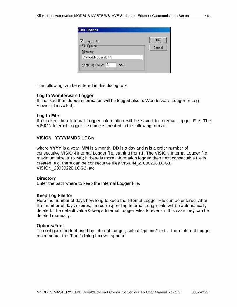
Klinkmann Automation MODBUS MASTER/SLAVE Serial and Ethernet Communication Server 46
MODBUS MASTER/SLAVE Serial&Ethernet Comm. Server Ver 1.x User Manual Rev 2.2 380xxm22
The following can be entered in this dialog box: Log to Wonderware Logger If checked then debug information will be logged also to Wonderware Logger or Log Viewer (if installed). Log to File If checked then Internal Logger information will be saved to Internal Logger File. The VISION Internal Logger file name is created in the following format:
VISION _YYYYMMDD.LOGn where YYYY is a year, MM is a month, DD is a day and n is a order number of consecutive VISION Internal Logger file, starting from 1. The VISION Internal Logger file maximum size is 16 MB; if there is more information logged then next consecutive file is created, e.g. there can be consecutive files VISION_20030228.LOG1, VISION_20030228.LOG2, etc. Directory Enter the path where to keep the Internal Logger File.
Keep Log File for Here the number of days how long to keep the Internal Logger File can be entered. After this number of days expires, the corresponding Internal Logger File will be automatically deleted. The default value 0 keeps Internal Logger Files forever - in this case they can be deleted manually. Options/Font To configure the font used by Internal Logger, select Options/Font… from Internal Logger main menu - the “Font” dialog box will appear:
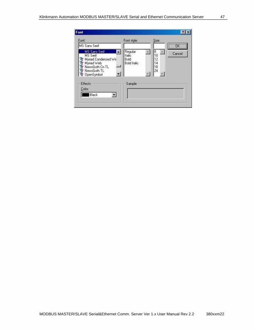
Klinkmann Automation MODBUS MASTER/SLAVE Serial and Ethernet Communication Server 47
MODBUS MASTER/SLAVE Serial&Ethernet Comm. Server Ver 1.x User Manual Rev 2.2 380xxm22
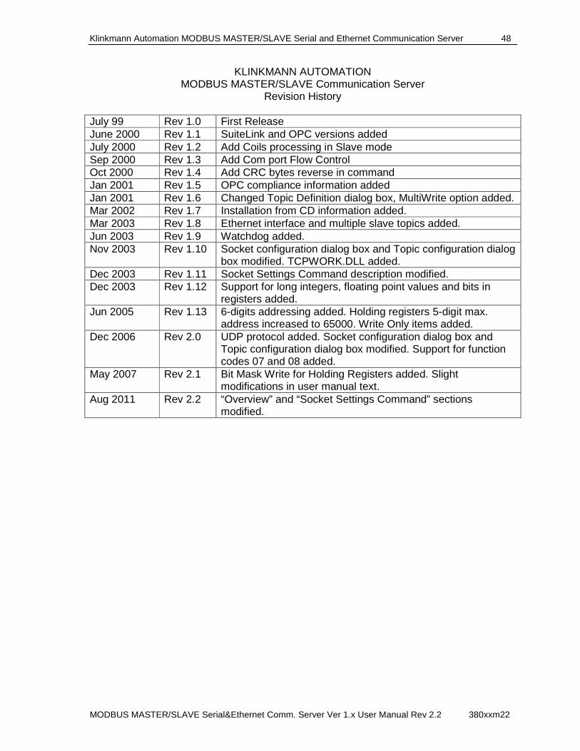
Klinkmann Automation MODBUS MASTER/SLAVE Serial and Ethernet Communication Server 48
MODBUS MASTER/SLAVE Serial&Ethernet Comm. Server Ver 1.x User Manual Rev 2.2 380xxm22
KLINKMANN AUTOMATION MODBUS MASTER/SLAVE Communication Server
Revision History
July 99 Rev 1.0 First Release June 2000 Rev 1.1 SuiteLink and OPC versions added July 2000 Rev 1.2 Add Coils processing in Slave mode Sep 2000 Rev 1.3 Add Com port Flow Control Oct 2000 Rev 1.4 Add CRC bytes reverse in command Jan 2001 Rev 1.5 OPC compliance information added Jan 2001 Rev 1.6 Changed Topic Definition dialog box, MultiWrite option added. Mar 2002 Rev 1.7 Installation from CD information added. Mar 2003 Rev 1.8 Ethernet interface and multiple slave topics added. Jun 2003 Rev 1.9 Watchdog added. Nov 2003 Rev 1.10 Socket configuration dialog box and Topic configuration dialog
box modified. TCPWORK.DLL added. Dec 2003 Rev 1.11 Socket Settings Command description modified. Dec 2003 Rev 1.12 Support for long integers, floating point values and bits in
registers added. Jun 2005 Rev 1.13 6-digits addressing added. Holding registers 5-digit max.
address increased to 65000. Write Only items added. Dec 2006 Rev 2.0 UDP protocol added. Socket configuration dialog box and
Topic configuration dialog box modified. Support for function codes 07 and 08 added.
May 2007 Rev 2.1 Bit Mask Write for Holding Registers added. Slight modifications in user manual text.
Aug 2011 Rev 2.2 “Overview” and “Socket Settings Command” sections modified.