modbus and bacnet communication … rev g_bacnet.pdf · using a token passing process where...
TRANSCRIPT
FB-MODB Rev G
This manual must only be used by a qualifi ed heating installer / service technician. Read all instructions, including this manual, the Installation and Operation Manual, and the Service Manual, before installing. Perform steps in the order given. Failure to comply could result in severe personal injury, death, or substantial property damage.
� WARNING
Save this manual for future reference.
MODBUS AND BACNET COMMUNICATION INSTRUCTIONS
Crest Models: 0.75 - 5.0
2
Contents1. INTRODUCTION
Defi nitions .................................................................... 2Minimum System Requirements .................................. 2
2. MODBUS CONFIGURATION Addressing ................................................................... 3 Timing Specifi cations ................................................... 4 Parity ............................................................................ 4 Data Transmission Mode ............................................. 4 ModBus Board Diagnostics ......................................... 4 Internal Faults ......................................................... 4 ModBus Function Set ............................................. 5 ModBus Exception Codes ........................................... 63. MODBUS MEMORY MAP
Primary Data Tables .................................................... . 7Crest Boiler Memory Map ............................................ 7-8 Input Registers ....................................................... . 8 Holding Registers ................................................... . 8
Confi guration Bits ........................................................ . 84. BACNET CONFIGURATION ....................................... ..9 Addressing ................................................................... ..9 Timing Specifi cations ................................................... 10
Communication Board Diagnostics ............................. 10 Internal Faults ............................................................. 105. BACnet MEMORY MAP
Primary Data Tables .................................................... 11Crest Boiler Memory Map........................................11-12 Input Registers ....................................................... . 8 Holding Registers ................................................... 12
6. WIRING REQUIREMENTS Physical Wiring ............................................................ 13 Typical Boiler System Wiring .................................. 14-177 UNIT OPERATION Unit Operation with ModBus and BACnet
Communications .................................................... 18-218. TROUBLESHOOTING ........................................... 22-259. DIAGRAMS ........................................................... 26-33Revision Notes ................................................... Back Cover
1 Introduction
Abbreviation or Acronym MeaningASCII American Standard Code for Information Interchange
BACnet A data communication protocol for Building Automation and Control Networks
BAS Building Automation System
Baud (Baud Rate) Number of data bits transmitted per second (bps)
EMS Energy Management System
FDX Full-Duplex
HDX Half-Duplex
Hex Hexadecimal Number (0 - 9, A - F)
I/O Box Input/Output (I/O)
LSB Least Signifi cant Byte
ModBus® A serial, half-duplex data transmission protocol developed by AEG Modicon
MSB Most Signifi cant Byte
RS232 A standard for serial, full-duplex (FDX) transmission of data based on the RS232 Standard
RS485 A standard for serial transmission of data based on the RS-485 Standard
RTU Remote Terminal Unit
Defi nitions
Minimum System Requirements• BAS system or computer with a serial or USB port with a converter to RS-485.
Shielded twisted pair communication cable.
The information contained in this manual provides general guidelines for the implementation of ModBus / BACnet communication with the Lochinvar Crest boiler.
All ModBus networks are implemented utilizing a master-slave arrangement where all Crest boilers are slaves and the master is a building automation system capable of communicating over RS-485 serial connections. BACnet networks are implemented using a token passing process where multiple masters and slaves share a common RS-485 bus. The Lochinvar BACnet interface is a master only.

3
2 ModBus Confi guration
AddressingThe ModBus addressing space is comprised of 256 different addresss. • 0 is reserved for broadcast messages from the master device • 1 - 247 are free to use for each unique device • 248 - 255 are reserved
To set the ModBus address the dip switches can be set in either the 0 position or the 1 position. For switches set to the 1 position their value will be added together to determine the address.
For each switch set to the 1 position it has the following value:
Dip switch 1 = 1 Dip switch 2 = 2 Dip switch 3 = 4 Dip switch 4 = 8 Dip switch 5 = 16 Dip switch 6 = 32 Dip switch 7 = 64 Dip switch 8 = 128
Any dip switch set to 0 has a value equal to 0.
Example:
To set the address of the ModBus board to 50, dip switches 2, 5, and 6 have to be set to the 1 position. The address is determined by adding the values of all the dip switches together.
Address = Value of Dip switch 1 + Value of Dip switch 2 + Value of Dip switch 3 + Value of Dip switch 4 + Value of Dip switch 5 + Value of Dip switch 6 + Value of Dip switch 7 + Value of Dip switch 8
In this example:
Address = 0 + 2 + 0 + 0 + 16 + 32 + 0 + 0 = 50
The ModBus or BACnet communication board is equipped with a set of ten dip switches that are used to set the board confi guration (address, baud rate, and parity settings). The fi rst eight are used to set the address of each board. The ninth is used to set the baud rate. The tenth is used to set the parity.
LED’S
DIP SWITCHES
Figure 2-1_Communication Board
ModBus and BACnet InstructionsM
4
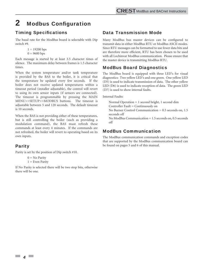
2 Modbus Confi gurationTiming Specifi cationsThe baud rate for the ModBus board is selectable with Dip switch #9.
1 = 19200 bps 0 = 9600 bps
Each message is started by at least 3.5 character times of silence. The maximum delay between frames is 1.5 character times.
When the system temperature and/or tank temperature is provided by the BAS to the boiler, it is critical that the temperature be updated every few seconds. If the boiler does not receive updated temperatures within a timeout period (installer adjustable), the control will revert to using its own sensor inputs (if sensors are connected). The timeout is programmable by pressing the MAIN MENU>>SETUP>>MODBUS buttons. The timeout is adjustable between 5 and 120 seconds. The default timeout is 10 seconds.
When the BAS is not providing either of these temperatures, but is still controlling the boiler (such as providing a modulation command), the BAS must refresh these commands at least every 4 minutes. If the commands are not refreshed, the boiler will revert to operating based on its own inputs.
ParityParity is set by the position of Dip switch #10.
0 = No Parity 1 = Even Parity
If No Parity is selected there will be two stop bits, otherwise there will be one.
Data Transmission ModeMany ModBus bus master devices can be confi gured to transmit data in either ModBus RTU or ModBus ASCII modes. Since RTU messages can be formatted to use fewer data bits and are therefore more effi cient, RTU has been chosen to be used with all Lochinvar ModBus communication. Please ensure that the master device is transmitting ModBus RTU.
ModBus Board DiagnosticsThe ModBus board is equipped with three LED’s for visual diagnostics: Two yellow LED’s and one green. One yellow LED (D5) is used to indicate transmission of data. The other yellow LED (D6) is used to indicate reception of data. The green LED (D7) is used to show internal faults.
Internal Faults:
Normal Operation = 1 second bright, 1 second dim Controller Fault = Continuously on No Burner Control Communication = 0.5 seconds on, 1.5 seconds off No ModBus Communication = 1.5 seconds on, 0.5 seconds off
ModBus CommunicationThe ModBus communication commands and exception codes that are supported by the ModBus communication board can be found on pages 5 and 6 of this manual.
ModBus and BACnet InstructionsM
5
2 ModBus Confi guration (continued)
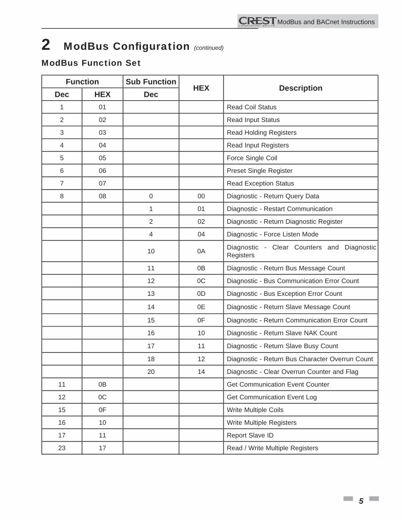
Function Sub FunctionHEX Description
Dec HEX Dec1 01 Read Coil Status
2 02 Read Input Status
3 03 Read Holding Registers
4 04 Read Input Registers
5 05 Force Single Coil
6 06 Preset Single Register
7 07 Read Exception Status
8 08 0 00 Diagnostic - Return Query Data
1 01 Diagnostic - Restart Communication
2 02 Diagnostic - Return Diagnostic Register
4 04 Diagnostic - Force Listen Mode
10 0A Diagnostic - Clear Counters and Diagnostic Registers
11 0B Diagnostic - Return Bus Message Count
12 0C Diagnostic - Bus Communication Error Count
13 0D Diagnostic - Bus Exception Error Count
14 0E Diagnostic - Return Slave Message Count
15 0F Diagnostic - Return Communication Error Count
16 10 Diagnostic - Return Slave NAK Count
17 11 Diagnostic - Return Slave Busy Count
18 12 Diagnostic - Return Bus Character Overrun Count
20 14 Diagnostic - Clear Overrun Counter and Flag
11 0B Get Communication Event Counter
12 0C Get Communication Event Log
15 0F Write Multiple Coils
16 10 Write Multiple Registers
17 11 Report Slave ID
23 17 Read / Write Multiple Registers
ModBus Function Set
ModBus and BACnet InstructionsM
6
2 ModBus Confi guration
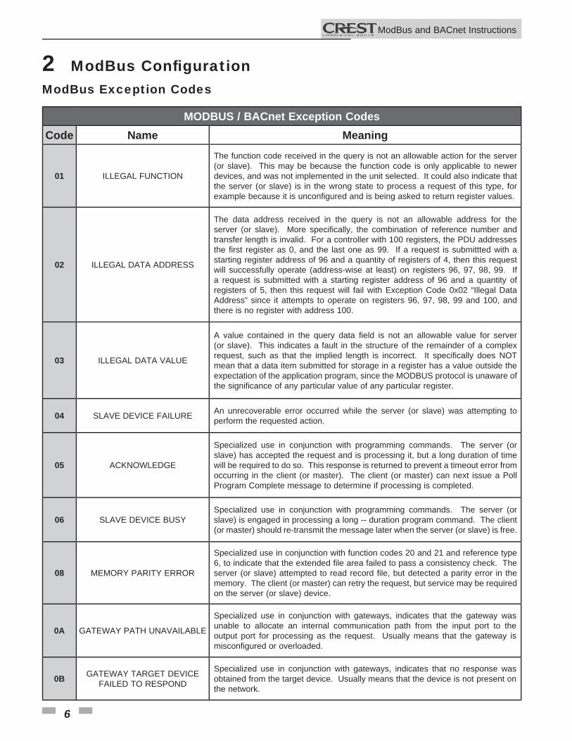
MODBUS / BACnet Exception CodesCode Name Meaning
01 ILLEGAL FUNCTION
The function code received in the query is not an allowable action for the server (or slave). This may be because the function code is only applicable to newer devices, and was not implemented in the unit selected. It could also indicate that the server (or slave) is in the wrong state to process a request of this type, for example because it is unconfi gured and is being asked to return register values.
02 ILLEGAL DATA ADDRESS
The data address received in the query is not an allowable address for the server (or slave). More specifi cally, the combination of reference number and transfer length is invalid. For a controller with 100 registers, the PDU addresses the fi rst register as 0, and the last one as 99. If a request is submittted with a starting register address of 96 and a quantity of registers of 4, then this request will successfully operate (address-wise at least) on registers 96, 97, 98, 99. If a request is submitted with a starting register address of 96 and a quantity of registers of 5, then this request will fail with Exception Code 0x02 “Illegal Data Address” since it attempts to operate on registers 96, 97, 98, 99 and 100, and there is no register with address 100.
03 ILLEGAL DATA VALUE
A value contained in the query data fi eld is not an allowable value for server (or slave). This indicates a fault in the structure of the remainder of a complex request, such as that the implied length is incorrect. It specifi cally does NOT mean that a data item submitted for storage in a register has a value outside the expectation of the application program, since the MODBUS protocol is unaware of the signifi cance of any particular value of any particular register.
04 SLAVE DEVICE FAILURE An unrecoverable error occurred while the server (or slave) was attempting to perform the requested action.
05 ACKNOWLEDGE
Specialized use in conjunction with programming commands. The server (or slave) has accepted the request and is processing it, but a long duration of time will be required to do so. This response is returned to prevent a timeout error from occurring in the client (or master). The client (or master) can next issue a Poll Program Complete message to determine if processing is completed.
06 SLAVE DEVICE BUSYSpecialized use in conjunction with programming commands. The server (or slave) is engaged in processing a long -- duration program command. The client (or master) should re-transmit the message later when the server (or slave) is free.
08 MEMORY PARITY ERROR
Specialized use in conjunction with function codes 20 and 21 and reference type 6, to indicate that the extended fi le area failed to pass a consistency check. The server (or slave) attempted to read record fi le, but detected a parity error in the memory. The client (or master) can retry the request, but service may be required on the server (or slave) device.
0A GATEWAY PATH UNAVAILABLE
Specialized use in conjunction with gateways, indicates that the gateway was unable to allocate an internal communication path from the input port to the output port for processing as the request. Usually means that the gateway is misconfi gured or overloaded.
0B GATEWAY TARGET DEVICE FAILED TO RESPOND
Specialized use in conjunction with gateways, indicates that no response was obtained from the target device. Usually means that the device is not present on the network.
ModBus Exception Codes
ModBus and BACnet InstructionsM
7
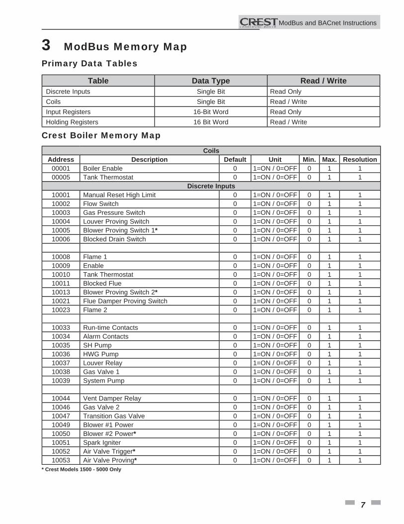
Primary Data Tables
Table Data Type Read / WriteDiscrete Inputs Single Bit Read OnlyCoils Single Bit Read / WriteInput Registers 16-Bit Word Read OnlyHolding Registers 16 Bit Word Read / Write
Crest Boiler Memory MapCoils
Address Description Default Unit Min. Max. Resolution00001 Boiler Enable 0 1=ON / 0=OFF 0 1 100005 Tank Thermostat 0 1=ON / 0=OFF 0 1 1
Discrete Inputs10001 Manual Reset High Limit 0 1=ON / 0=OFF 0 1 110002 Flow Switch 0 1=ON / 0=OFF 0 1 110003 Gas Pressure Switch 0 1=ON / 0=OFF 0 1 110004 Louver Proving Switch 0 1=ON / 0=OFF 0 1 110005 Blower Proving Switch 1* 0 1=ON / 0=OFF 0 1 110006 Blocked Drain Switch 0 1=ON / 0=OFF 0 1 1
10008 Flame 1 0 1=ON / 0=OFF 0 1 110009 Enable 0 1=ON / 0=OFF 0 1 110010 Tank Thermostat 0 1=ON / 0=OFF 0 1 110011 Blocked Flue 0 1=ON / 0=OFF 0 1 110013 Blower Proving Switch 2* 0 1=ON / 0=OFF 0 1 110021 Flue Damper Proving Switch 0 1=ON / 0=OFF 0 1 110023 Flame 2 0 1=ON / 0=OFF 0 1 1
10033 Run-time Contacts 0 1=ON / 0=OFF 0 1 110034 Alarm Contacts 0 1=ON / 0=OFF 0 1 110035 SH Pump 0 1=ON / 0=OFF 0 1 110036 HWG Pump 0 1=ON / 0=OFF 0 1 110037 Louver Relay 0 1=ON / 0=OFF 0 1 110038 Gas Valve 1 0 1=ON / 0=OFF 0 1 110039 System Pump 0 1=ON / 0=OFF 0 1 1
10044 Vent Damper Relay 0 1=ON / 0=OFF 0 1 110046 Gas Valve 2 0 1=ON / 0=OFF 0 1 110047 Transition Gas Valve 0 1=ON / 0=OFF 0 1 110049 Blower #1 Power 0 1=ON / 0=OFF 0 1 110050 Blower #2 Power* 0 1=ON / 0=OFF 0 1 110051 Spark Igniter 0 1=ON / 0=OFF 0 1 110052 Air Valve Trigger* 0 1=ON / 0=OFF 0 1 110053 Air Valve Proving* 0 1=ON / 0=OFF 0 1 1
* Crest Models 1500 - 5000 Only
3 ModBus Memory Map
ModBus and BACnet InstructionsM
8
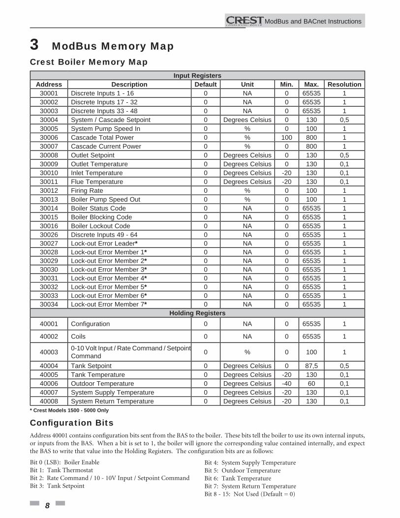
Input RegistersAddress Description Default Unit Min. Max. Resolution
30001 Discrete Inputs 1 - 16 0 NA 0 65535 130002 Discrete Inputs 17 - 32 0 NA 0 65535 130003 Discrete Inputs 33 - 48 0 NA 0 65535 130004 System / Cascade Setpoint 0 Degrees Celsius 0 130 0,530005 System Pump Speed In 0 % 0 100 130006 Cascade Total Power 0 % 100 800 130007 Cascade Current Power 0 % 0 800 130008 Outlet Setpoint 0 Degrees Celsius 0 130 0,530009 Outlet Temperature 0 Degrees Celsius 0 130 0,130010 Inlet Temperature 0 Degrees Celsius -20 130 0,130011 Flue Temperature 0 Degrees Celsius -20 130 0,130012 Firing Rate 0 % 0 100 130013 Boiler Pump Speed Out 0 % 0 100 130014 Boiler Status Code 0 NA 0 65535 130015 Boiler Blocking Code 0 NA 0 65535 130016 Boiler Lockout Code 0 NA 0 65535 130026 Discrete Inputs 49 - 64 0 NA 0 65535 130027 Lock-out Error Leader* 0 NA 0 65535 130028 Lock-out Error Member 1* 0 NA 0 65535 130029 Lock-out Error Member 2* 0 NA 0 65535 130030 Lock-out Error Member 3* 0 NA 0 65535 130031 Lock-out Error Member 4* 0 NA 0 65535 130032 Lock-out Error Member 5* 0 NA 0 65535 130033 Lock-out Error Member 6* 0 NA 0 65535 130034 Lock-out Error Member 7* 0 NA 0 65535 1
Holding Registers40001 Confi guration 0 NA 0 65535 1
40002 Coils 0 NA 0 65535 1
40003 0-10 Volt Input / Rate Command / Setpoint Command 0 % 0 100 1
40004 Tank Setpoint 0 Degrees Celsius 0 87,5 0,540005 Tank Temperature 0 Degrees Celsius -20 130 0,140006 Outdoor Temperature 0 Degrees Celsius -40 60 0,140007 System Supply Temperature 0 Degrees Celsius -20 130 0,140008 System Return Temperature 0 Degrees Celsius -20 130 0,1
* Crest Models 1500 - 5000 Only
Crest Boiler Memory Map
3 ModBus Memory Map
Confi guration BitsAddress 40001 contains confi guration bits sent from the BAS to the boiler. These bits tell the boiler to use its own internal inputs, or inputs from the BAS. When a bit is set to 1, the boiler will ignore the corresponding value contained internally, and expect the BAS to write that value into the Holding Registers. The confi guration bits are as follows:
Bit 4: System Supply TemperatureBit 5: Outdoor TemperatureBit 6: Tank TemperatureBit 7: System Return TemperatureBit 8 - 15: Not Used (Default = 0)
Bit 0 (LSB): Boiler EnableBit 1: Tank ThermostatBit 2: Rate Command / 10 - 10V Input / Setpoint CommandBit 3: Tank Setpoint
ModBus and BACnet InstructionsM
9
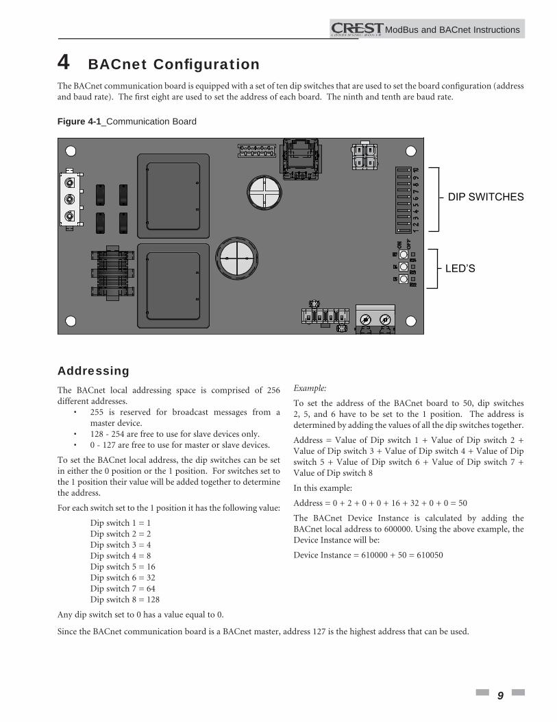
4 BACnet Confi guration
ModBus and BACnet InstructionsM
AddressingThe BACnet local addressing space is comprised of 256 different addresses. • 255 is reserved for broadcast messages from a master device. • 128 - 254 are free to use for slave devices only. • 0 - 127 are free to use for master or slave devices.
To set the BACnet local address, the dip switches can be set in either the 0 position or the 1 position. For switches set to the 1 position their value will be added together to determine the address.
For each switch set to the 1 position it has the following value:
Dip switch 1 = 1 Dip switch 2 = 2 Dip switch 3 = 4 Dip switch 4 = 8 Dip switch 5 = 16 Dip switch 6 = 32 Dip switch 7 = 64 Dip switch 8 = 128
Any dip switch set to 0 has a value equal to 0.
Example:
To set the address of the BACnet board to 50, dip switches 2, 5, and 6 have to be set to the 1 position. The address is determined by adding the values of all the dip switches together.
Address = Value of Dip switch 1 + Value of Dip switch 2 + Value of Dip switch 3 + Value of Dip switch 4 + Value of Dip switch 5 + Value of Dip switch 6 + Value of Dip switch 7 + Value of Dip switch 8
In this example:
Address = 0 + 2 + 0 + 0 + 16 + 32 + 0 + 0 = 50
The BACnet Device Instance is calculated by adding the BACnet local address to 600000. Using the above example, the Device Instance will be:
Device Instance = 610000 + 50 = 610050
The BACnet communication board is equipped with a set of ten dip switches that are used to set the board confi guration (address and baud rate). The fi rst eight are used to set the address of each board. The ninth and tenth are baud rate.
LED’S
DIP SWITCHES
Figure 4-1_Communication Board
Since the BACnet communication board is a BACnet master, address 127 is the highest address that can be used.
10
4 BACnet Confi guration
ModBus and BACnet InstructionsM
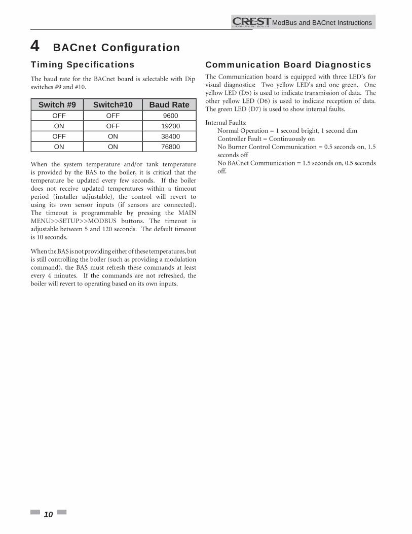
Timing Specifi cationsThe baud rate for the BACnet board is selectable with Dip switches #9 and #10.
Communication Board DiagnosticsThe Communication board is equipped with three LED’s for visual diagnostics: Two yellow LED’s and one green. One yellow LED (D5) is used to indicate transmission of data. The other yellow LED (D6) is used to indicate reception of data. The green LED (D7) is used to show internal faults.
Internal Faults: Normal Operation = 1 second bright, 1 second dim Controller Fault = Continuously on No Burner Control Communication = 0.5 seconds on, 1.5 seconds off No BACnet Communication = 1.5 seconds on, 0.5 seconds off.
Switch #9 Switch#10 Baud RateOFF OFF 9600ON OFF 19200OFF ON 38400ON ON 76800
When the system temperature and/or tank temperature is provided by the BAS to the boiler, it is critical that the temperature be updated every few seconds. If the boiler does not receive updated temperatures within a timeout period (installer adjustable), the control will revert to using its own sensor inputs (if sensors are connected). The timeout is programmable by pressing the MAIN MENU>>SETUP>>MODBUS buttons. The timeout is adjustable between 5 and 120 seconds. The default timeout is 10 seconds.
When the BAS is not providing either of these temperatures, but is still controlling the boiler (such as providing a modulation command), the BAS must refresh these commands at least every 4 minutes. If the commands are not refreshed, the boiler will revert to operating based on its own inputs.

5 BACnet Memory Map
ModBus and BACnet InstructionsM
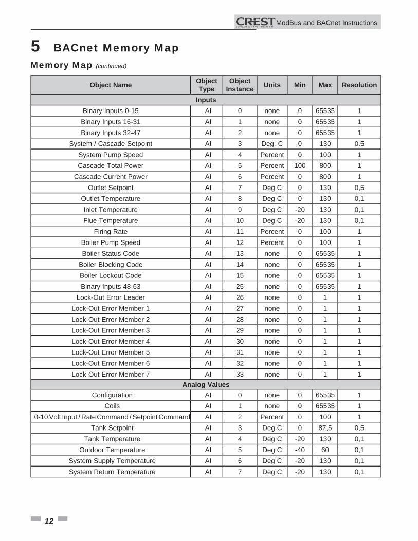
Primary Data Tables
Object Type Data Type Read / WriteBinary Input (BI) Single Bit Read Only
Binary Value (BV) Single Bit Read / WriteAnalog Input (AI) 16-Bit Word Read Only
Analog Value (AV) 16 Bit Word Read / Write
Memory Map
Object Name Object Type
ObjectInstance Units Min Max Resolution
Binary ValuesBoiler Enable BV 0 none 0 1 1
Tank Thermostat BV 4 none 0 1 1Binary Inputs
Manual Reset High Limit BI 0 none 0 1 1Flow Switch BI 1 none 0 1 1
Gas Pressure Switch BI 2 none 0 1 1Louver Proving Switch BI 3 none 0 1 1
Air Pressure Switch BI 4 none 0 1 1Blocked Drain Switch BI 5 none 0 1 1
Flame 1 BI 7 none 0 1 1Enable BI 8 none 0 1 1
Tank Thermostat BI 9 none 0 1 1Fan 1 Proving Switch BI 10 none 0 1 1Fan 2 Proving Switch BI 12 none 0 1 1Flue Damper Switch BI 20 none 0 1 1
Flame 2 BI 22 none 0 1 1Run Time Contacts BI 32 none 0 1 1
Alarm Contacts BI 33 none 0 1 1Boiler Pump BI 34 none 0 1 1DHW Pump BI 35 none 0 1 1
Louver Relay BI 36 none 0 1 1Gas Valve 1 BI 37 none 0 1 1
System Pump BI 38 none 0 1 1Flue Damper Output BI 43 none 0 1 1
Gas Valve 2 BI 45 none 0 1 1Transition Gas Valve** BI 46 none 0 1 1
Main Fan 1 BI 48 none 0 1 1Main Fan 2* BI 49 none 0 1 1
External Spark / HSI BI 50 none 0 1 1Air Valve Trigger** BI 51 none 0 1 1Air Valve Proving** BI 52 none 0 1 1
* Crest Models 1500 - 5000 Only** Crest Models 751- 1501 Only 11
12
5 BACnet Memory Map
ModBus and BACnet InstructionsM
Object Name Object Type
ObjectInstance Units Min Max Resolution
InputsBinary Inputs 0-15 AI 0 none 0 65535 1
Binary Inputs 16-31 AI 1 none 0 65535 1Binary Inputs 32-47 AI 2 none 0 65535 1
System / Cascade Setpoint AI 3 Deg. C 0 130 0.5System Pump Speed AI 4 Percent 0 100 1Cascade Total Power AI 5 Percent 100 800 1
Cascade Current Power AI 6 Percent 0 800 1Outlet Setpoint AI 7 Deg C 0 130 0,5
Outlet Temperature AI 8 Deg C 0 130 0,1Inlet Temperature AI 9 Deg C -20 130 0,1Flue Temperature AI 10 Deg C -20 130 0,1
Firing Rate AI 11 Percent 0 100 1Boiler Pump Speed AI 12 Percent 0 100 1Boiler Status Code AI 13 none 0 65535 1
Boiler Blocking Code AI 14 none 0 65535 1Boiler Lockout Code AI 15 none 0 65535 1Binary Inputs 48-63 AI 25 none 0 65535 1
Lock-Out Error Leader AI 26 none 0 1 1Lock-Out Error Member 1 AI 27 none 0 1 1Lock-Out Error Member 2 AI 28 none 0 1 1Lock-Out Error Member 3 AI 29 none 0 1 1Lock-Out Error Member 4 AI 30 none 0 1 1Lock-Out Error Member 5 AI 31 none 0 1 1Lock-Out Error Member 6 AI 32 none 0 1 1Lock-Out Error Member 7 AI 33 none 0 1 1
Analog ValuesConfi guration AI 0 none 0 65535 1
Coils AI 1 none 0 65535 10-10 Volt Input / Rate Command / Setpoint Command AI 2 Percent 0 100 1
Tank Setpoint AI 3 Deg C 0 87,5 0,5Tank Temperature AI 4 Deg C -20 130 0,1
Outdoor Temperature AI 5 Deg C -40 60 0,1System Supply Temperature AI 6 Deg C -20 130 0,1System Return Temperature AI 7 Deg C -20 130 0,1
Memory Map (continued)
13
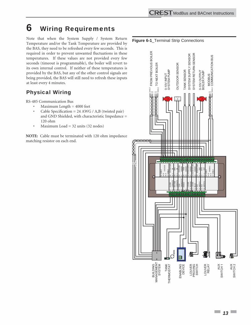
6 Wiring Requirements
RS-485 Communication Bus • Maximum Length = 4000 feet • Cable Specifi cation = 24 AWG / A,B (twisted pair) and GND Shielded, with characteristic Impedance = 120 ohm • Maximum Load = 32 units (32 nodes)
NOTE: Cable must be terminated with 120 ohm impedance matching resistor on each end.
Note that when the System Supply / System Return Temperature and/or the Tank Temperature are provided by the BAS, they need to be refreshed every few seconds. This is required in order to prevent unwanted fl uctuations in these temperatures. If these values are not provided every few seconds (timeout is programmable), the boiler will revert to its own internal control. If neither of these temperatures is provided by the BAS, but any of the other control signals are being provided, the BAS will still need to refresh these inputs at least every 4 minutes.
Physical Wiring
Figure 6-1_Terminal Strip Connections
1 2 3 4 5 6 7 8 9 10 11 12 13 14 15 16
ALA
RMCO
NTA
CTS
RUN
TIM
ECO
NTA
CTS
TAN
KTH
ERM
OST
AT
ENA
BLE
LOU
VER
PRO
VIN
GLO
UVER
RELA
YA
UX
SWIT
CH 1
AU
XSW
ITCH
2
40 39 38 37 36 35 34 33 32 31 30 29 28 27 26 25 24 23 22 21 20 19 18 17
CASC
AD
E
SYST
EM P
UMP
IN BMS
INO
UTD
OO
RSE
NSO
R
SEN
SOR
SEN
SOR
SEN
SOR
TAN
K
SYST
EM S
UPPL
Y
SYST
EM R
ETUR
N
BOIL
ER P
UMP
OU
T
OU
TRA
TE
MO
DBU
S
SHIE
LD
SHIE
LD
B A - + +- - -+ + SHIE
LD
SHIE
LD
B A
BU
ILD
ING
MA
NA
GEM
EN
TS
YSTE
M
TAN
KTH
ER
MO
STA
T
EN
AB
LIN
GD
EV
ICE
LOU
VER
PR
OV
ING
SW
ITC
H
LOU
VER
RE
LAY
AU
XS
WIT
CH
1
AU
XS
WIT
CH
2
FRO
M P
RE
VIO
US
BO
ILE
R
TO N
EXT
BO
ILER
A B B ASH
IELD
SH
IELD 0-
10V
INP
UT
SYS
TEM
PU
MP
OU
TDO
OR
SE
NS
OR
TAN
K S
EN
SO
RS
YSTE
M S
UP
PLY
SE
NS
OR
SYS
TEM
RE
TUR
N S
EN
SO
R
0-10
V O
UTP
UT
BO
ILE
R P
UM
P
MO
DBU
SC
OM
MU
NIC
ATIO
N B
US
SH
IELD
AB
B
A
SH
IELD
ModBus and BACnet InstructionsM
14
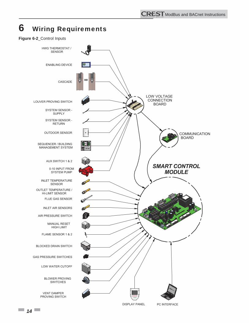
6 Wiring RequirementsFigure 6-2_Control Inputs
GAS PRESSURE SWITCHES
HWG THERMOSTAT / SENSOR
ENABLING DEVICE
SYSTEM SENSOR -SUPPLY
OUTDOOR SENSOR
SEQUENCER / BUILDINGMANAGEMENT SYSTEM
LOW VOLTAGE CONNECTION
BOARD
INLET TEMPERATURESENSOR
OUTLET TEMPERATURE /HI-LIMIT SENSOR
FLUE GAS SENSOR
LOUVER PROVING SWITCH
FLAME SENSOR 1 & 2
LOW WATER CUTOFF
BLOCKED DRAIN SWITCH
DISPLAY PANEL PC INTERFACE
SMART CONTROLMODULE
AIR PRESSURE SWITCH
SYSTEM SENSOR -RETURN
AUX SWITCH 1 & 2
0-10 INPUT FROMSYSTEM PUMP
BLOWER PROVING SWITCHES
CASCADE
INLET AIR SENSORS
MANUAL RESET HIGH LIMIT
VENT DAMPERPROVING SWITCH
COMMUNICATIONBOARD
ModBus and BACnet InstructionsM
15
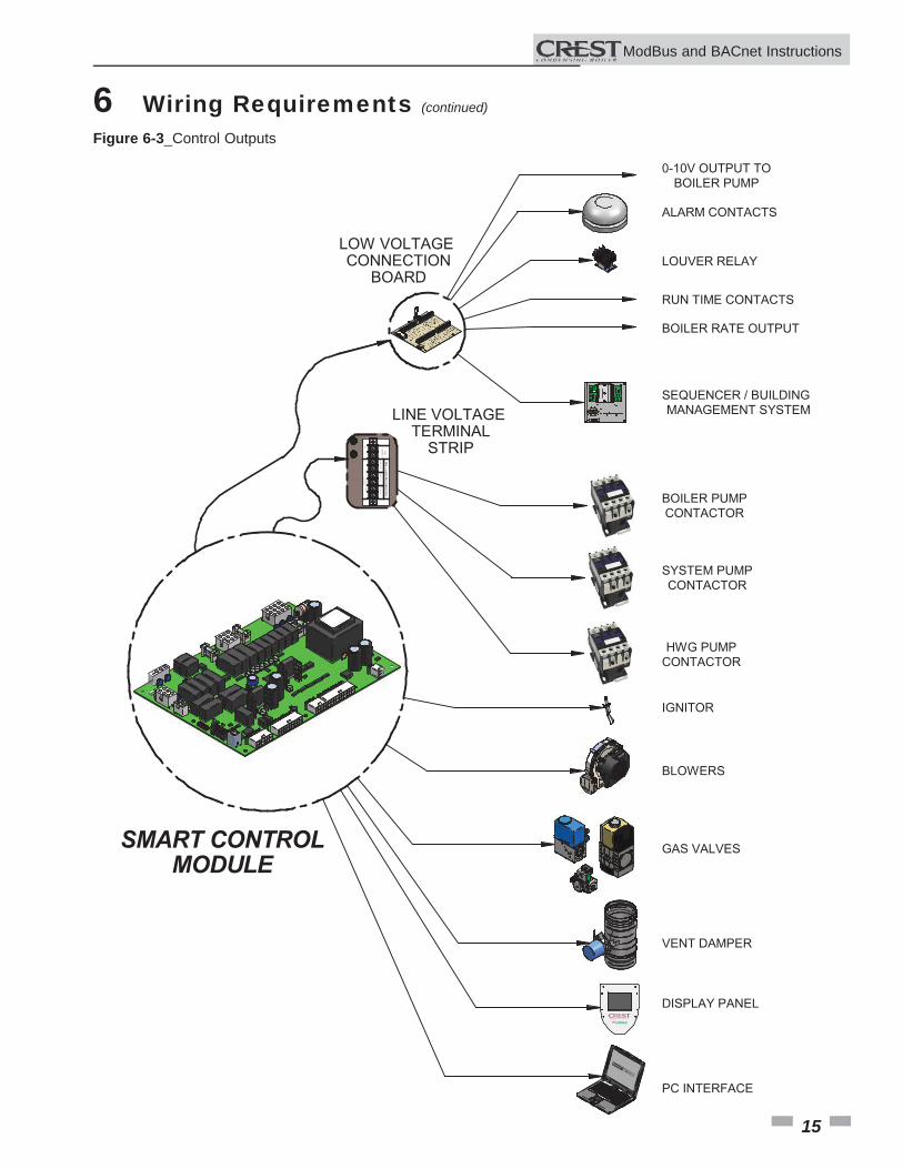
6 Wiring Requirements (continued)
Figure 6-3_Control Outputs
LOW VOLTAGE CONNECTION
BOARD
SMART CONTROLMODULE
ALARM CONTACTS
LOUVER RELAY
RUN TIME CONTACTS
SEQUENCER / BUILDINGMANAGEMENT SYSTEM
BOILER PUMPCONTACTOR
SYSTEM PUMPCONTACTOR
HWG PUMPCONTACTOR
IGNITOR
BLOWERS
GAS VALVES
BOILER RATE OUTPUT
DISPLAY PANEL
PC INTERFACE
120VSU
PPLYSYSTEM
PUM
PBO
ILER PUM
PDHW
PUM
P
MAX. 1.5 AMPS PER CONNECTION
NL
FIELD SUPPLIED CO
NTACTO
R MU
STBE INST
ALLED
LINE VOLTAGE TERMINAL
STRIP
0-10V OUTPUT TOBOILER PUMP
VENT DAMPER
ModBus and BACnet InstructionsM
16
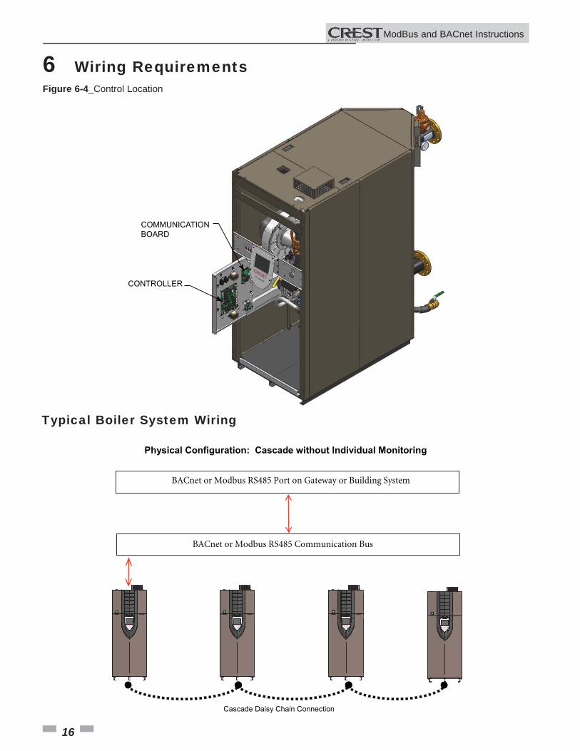
6 Wiring RequirementsFigure 6-4_Control Location
COMMUNICATIONBOARD
CONTROLLER
Typical Boiler System Wiring
Cascade Daisy Chain Connection
BACnet or Modbus RS485 Communication Bus
BACnet or Modbus RS485 Port on Gateway or Building System
Physical Configuration: Cascade without Individual Monitoring
ModBus and BACnet InstructionsM
17
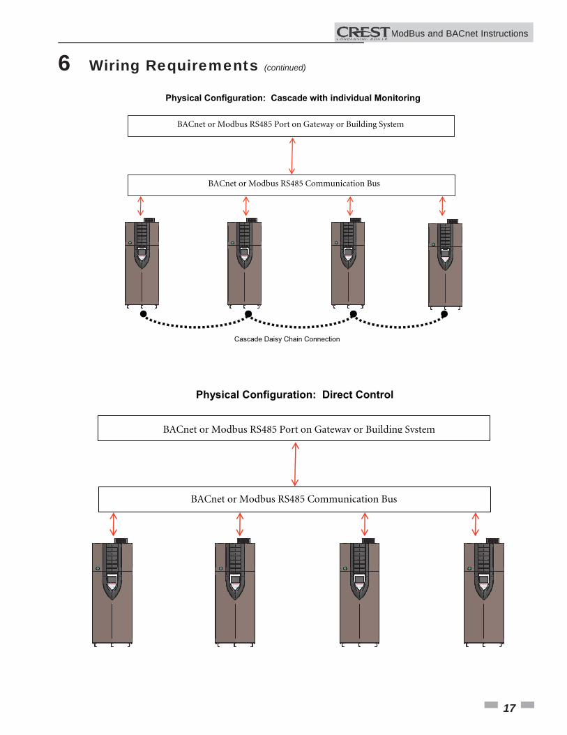
6 Wiring Requirements (continued)
BACnet or Modbus RS485 Communication Bus
BACnet or Modbus RS485 Port on Gateway or Building System
Physical Configuration: Direct Control
Cascade Daisy Chain Connection
BACnet or Modbus RS485 Communication Bus
BACnet or Modbus RS485 Port on Gateway or Building System
Physical Configuration: Cascade with individual Monitoring
ModBus and BACnet InstructionsM
18
7 Unit OperationUnit Operation with ModBus / BACnet CommunicationsTo control a Crest boiler through a Building Management System communicating through ModBus or BACnet, the Crest Demand Confi guration must be set to one of three options. These confi gurations allow different control points for a variety of applications. The confi guration can be set by selecting Main Menu>>Setup>>BMS.
NOTE: To ensure proper operation re-send the confi guration bits to holding register 40001 or Object AV0 prior to issuing a command.
The Crest boiler is equipped with a ModBus communication timer. This timer is programmable from 0 - 120 seconds. The timer can be programmed from the ModBus Setup Menu by selecting Main Menu>>Setup>>ModBus. The purpose of the timer is to ensure proper temperature data is communicated to the boiler in a timely manner. Additionally, it will provide for fail safe operation should ModBus communication be lost. This timer will cause the unit to revert back to internal unit controls should the ModBus communication be interrupted longer than the ModBus timer. The timer is reset every time a ModBus write command is received with updated temperatures or commands. It is the recommendation of Lochinvar that this timer be set to the shortest value possible.
When controlling a Crest boiler through a Building Automation System (BAS), it is very important to ensure that the correct confi guration bits are sent to holding register 40001 or Object AV0, and that the correct data and enable signals are sent to holding registers 40002 - 40007 or Objects AV1 - AV6, per the demand confi guration.
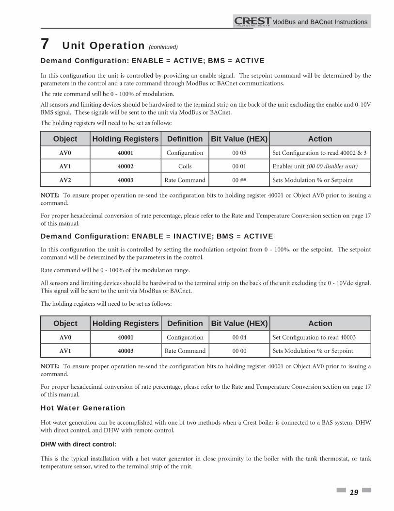
Demand Confi guration: ENABLE = ACTIVE; BMS = INACTIVEIn this confi guration the unit is controlled by setting the setpoints locally on the boiler and providing an enable signal through ModBus or BACnet communications.
All sensors and limiting devices should be hardwired to the terminal strip on the back of the unit excluding the enable signal. This signal will be sent to the unit via ModBus.
The holding registers will need to be set as follows:
ModBus and BACnet InstructionsM
Object Holding Registers Defi nition Bit Value (HEX) ActionAV0 40001 Confi guration 00 01 Set Confi guration to read 40002
AV1 40002 Coils 00 01 Enables unit (00 00 disables unit)
19
7 Unit Operation (continued)
Demand Confi guration: ENABLE = INACTIVE; BMS = ACTIVE
In this confi guration the unit is controlled by setting the modulation setpoint from 0 - 100%, or the setpoint. The setpoint command will be determined by the parameters in the control.
Rate command will be 0 - 100% of the modulation range.
All sensors and limiting devices should be hardwired to the terminal strip on the back of the unit excluding the 0 - 10Vdc signal. This signal will be sent to the unit via ModBus or BACnet.
The holding registers will need to be set as follows:
For proper hexadecimal conversion of rate percentage, please refer to the Rate and Temperature Conversion section on page 17 of this manual.
NOTE: To ensure proper operation re-send the confi guration bits to holding register 40001 or Object AV0 prior to issuing a command.
Hot Water Generation
Hot water generation can be accomplished with one of two methods when a Crest boiler is connected to a BAS system, DHW with direct control, and DHW with remote control.
DHW with direct control:
This is the typical installation with a hot water generator in close proximity to the boiler with the tank thermostat, or tank temperature sensor, wired to the terminal strip of the unit.
Demand Confi guration: ENABLE = ACTIVE; BMS = ACTIVE
In this confi guration the unit is controlled by providing an enable signal. The setpoint command will be determined by the parameters in the control and a rate command through ModBus or BACnet communications.
The rate command will be 0 - 100% of modulation.
All sensors and limiting devices should be hardwired to the terminal strip on the back of the unit excluding the enable and 0-10V BMS signal. These signals will be sent to the unit via ModBus or BACnet.
The holding registers will need to be set as follows:
NOTE: To ensure proper operation re-send the confi guration bits to holding register 40001 or Object AV0 prior to issuing a command.
For proper hexadecimal conversion of rate percentage, please refer to the Rate and Temperature Conversion section on page 17 of this manual.
ModBus and BACnet InstructionsM
Object Holding Registers Defi nition Bit Value (HEX) ActionAV0 40001 Confi guration 00 05 Set Confi guration to read 40002 & 3
AV1 40002 Coils 00 01 Enables unit (00 00 disables unit)
AV2 40003 Rate Command 00 ## Sets Modulation % or Setpoint
Object Holding Registers Defi nition Bit Value (HEX) ActionAV0 40001 Confi guration 00 04 Set Confi guration to read 40003
AV1 40003 Rate Command 00 00 Sets Modulation % or Setpoint
20
7 Unit Operation
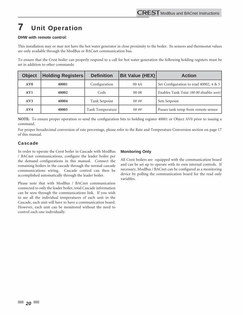
Cascade
In order to operate the Crest boiler in Cascade with ModBus / BACnet communications, confi gure the leader boiler per the demand confi gurations in this manual. Connect the remaining boilers in the cascade through the normal cascade communications wiring. Cascade control can then be accomplished automatically through the leader boiler.
Please note that with ModBus / BACnet communication connected to only the leader boiler, total Cascade information can be seen through the communications link. If you wish to see all the individual temperatures of each unit in the Cascade, each unit will have to have a communication board. However, each unit can be monitored without the need to control each one individually.
DHW with remote control:
This installation may or may not have the hot water generator in close proximity to the boiler. Its sensors and thermostat values are only available through the ModBus or BACnet communication bus.
To ensure that the Crest boiler can properly respond to a call for hot water generation the following holding registers must be set in addition to other commands:
For proper hexadecimal conversion of rate percentage, please refer to the Rate and Temperature Conversion section on page 17 of this manual.
NOTE: To ensure proper operation re-send the confi guration bits to holding register 40001 or Object AV0 prior to issuing a command.
Monitoring Only
All Crest boilers are equipped with the communication board and can be set up to operate with its own internal controls. If necessary, ModBus / BACnet can be confi gured as a monitoring device by polling the communication board for the read only variables.
ModBus and BACnet InstructionsM
Object Holding Registers Defi nition Bit Value (HEX) ActionAV0 40001 Confi guration 00 4A Set Confi guration to read 40002, 4 & 5
AV1 40002 Coils 00 08 Enables Tank Tstat (00 00 disables unit)
AV3 40004 Tank Setpoint 0# ## Sets Setpoint
AV4 40005 Tank Temperature 0# ## Passes tank temp from remote sensor
21
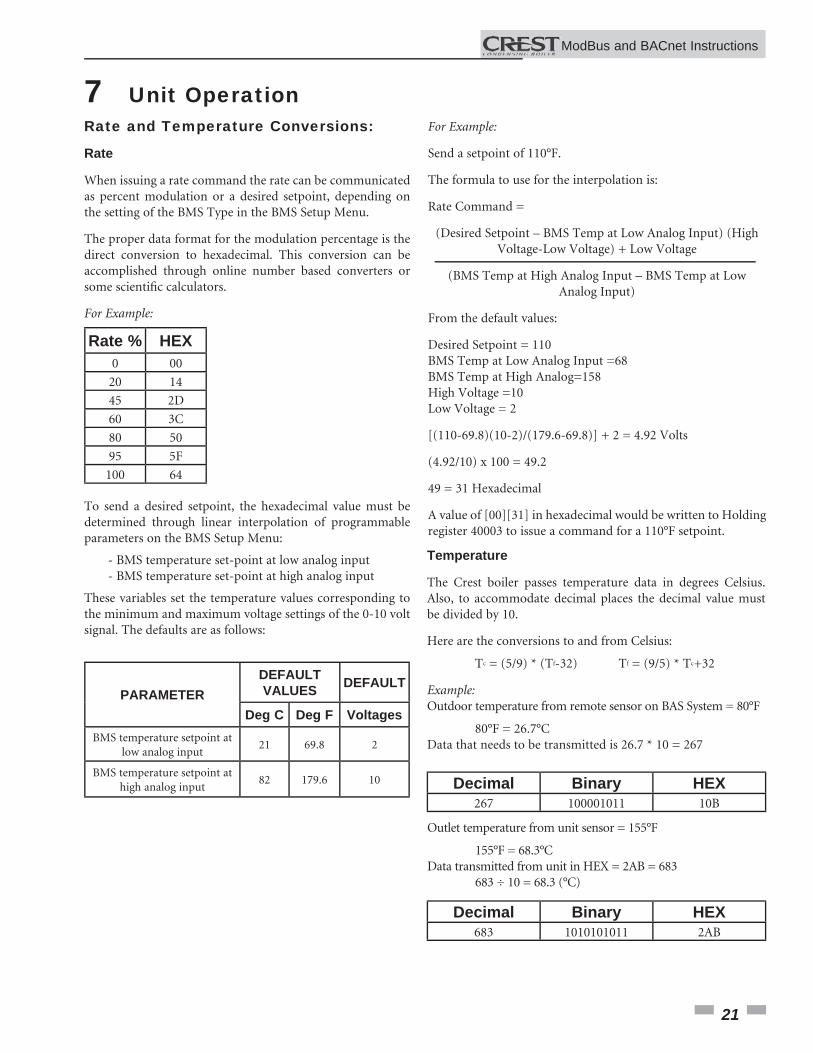
Temperature
The Crest boiler passes temperature data in degrees Celsius. Also, to accommodate decimal places the decimal value must be divided by 10.
Here are the conversions to and from Celsius:
Tc = (5/9) * (Tf-32) Tf = (9/5) * Tc+32
Example:Outdoor temperature from remote sensor on BAS System = 80°F
80°F = 26.7°CData that needs to be transmitted is 26.7 * 10 = 267
Decimal Binary HEX267 100001011 10B
Outlet temperature from unit sensor = 155°F
155°F = 68.3°CData transmitted from unit in HEX = 2AB = 683 683 ÷ 10 = 68.3 (°C)
Decimal Binary HEX683 1010101011 2AB
Rate and Temperature Conversions:
Rate
When issuing a rate command the rate can be communicated as percent modulation or a desired setpoint, depending on the setting of the BMS Type in the BMS Setup Menu.
The proper data format for the modulation percentage is the direct conversion to hexadecimal. This conversion can be accomplished through online number based converters or some scientifi c calculators.
For Example:
To send a desired setpoint, the hexadecimal value must be determined through linear interpolation of programmable parameters on the BMS Setup Menu:
- BMS temperature set-point at low analog input - BMS temperature set-point at high analog input
These variables set the temperature values corresponding to the minimum and maximum voltage settings of the 0-10 volt signal. The defaults are as follows:
Rate % HEX0 00
20 14
45 2D
60 3C
80 50
95 5F
100 64
PARAMETERDEFAULT VALUES DEFAULT
Deg C Deg F VoltagesBMS temperature setpoint at
low analog input21 69.8 2
BMS temperature setpoint at high analog input
82 179.6 10
For Example:
Send a setpoint of 110°F.
The formula to use for the interpolation is:
Rate Command =
(Desired Setpoint – BMS Temp at Low Analog Input) (High Voltage-Low Voltage) + Low Voltage
(BMS Temp at High Analog Input – BMS Temp at Low Analog Input)
From the default values:
Desired Setpoint = 110BMS Temp at Low Analog Input =68BMS Temp at High Analog=158High Voltage =10Low Voltage = 2
[(110-69.8)(10-2)/(179.6-69.8)] + 2 = 4.92 Volts
(4.92/10) x 100 = 49.2
49 = 31 Hexadecimal
A value of [00][31] in hexadecimal would be written to Holding register 40003 to issue a command for a 110°F setpoint.
7 Unit Operation
ModBus and BACnet InstructionsM
22
8 Troubleshooting Should you encounter problems communicating over ModBus, the following items should be checked in this order:
1. Physical Layer2. Communications Confi guration and Port Settings3. ModBus Error Codes4. Unit Status / Blocking / Lockout Codes
Physical Layer1. Check that all components have power (Boiler, Gateway, BAS Master)2. Check all wire lengths. Are any drops too long?3. Check proper shield grounding4. Check A, B terminal connections5. Check for Terminating Resistors (120 ohms)6. Check for broken wires
Communications1. Check Dip Switch Confi guration of MTR-01 Board2. Check Baud Rate (9600, 19200)3. Check Parity4. Check Slave ID5. Check Port Setting on Master, Gateway, and Computers
ModBus Error Codes1. Check ModBus communication for error codes (see page 6 for ModBus Exception Codes)2. Check ModBus PDU3. Check Slave ID4. Check ModBus Command5. Check Confi guration bits for Holding Register 400016. Check Commands and data for Holding Registers 40002 - 40007
Unit Status CodesSee Codes in this section
Boiler StatusThe Crest boiler displays a boiler state code on the Building Screen to help aid in troubleshooting. The boiler state indicates what the boiler is actually doing. This state should be compared to the command issued and what is expected. If the boiler state does not agree with the command issued, check communication and confi guration.
Status Codes (Input Register 30014 or Analog Input AI13)2 = Heat Demand blocked due to high absolute outlet temperature3 = Heat Demand blocked due to high absolute fl ue temperature4 = Heat Demand blocked due to high absolute Delta T (Outlet - Inlet)7 = Heat Demand blocked due to changed Personality Plug8 = Heat Demand blocked due to Low 24 VAC9 = Outdoor shutdown10 = Block due to switch OFF boiler (ON/OFF of Display)12 = Block due to line frequency16 = Service function19 = DHW function Storage Tank21 = SH function Heat demand from Room Thermostat22 = SH function Heat demand from Boiler Management System23 = SH function Heat demand from Cascade30 = Heat demand activated by Freeze Protection32 = DHW Pump Delay33 = SH Pump Delay34 = No heat function (after pump delay)40 = Lockout
Blocking Codes (Input Register 30015 or Analog Input AI14)0 = No blocking5 = Blocking Due to Low 24 VAC Supply6 = Blocking MRHL is open8 = Blocking due to Switched OFF boiler (Display ENTER switch)10 = Blocking due to High Delta T14 = Blocking due to line frequency15 = Blocking due to high fl ue temperature11 = Blocking due to high outlet water temperature12 = Blocking due to anti-cycling time13 = Blocking due to changed ID Plug7 = Blocking due to high outdoor temperature
ModBus and BACnet InstructionsM
23
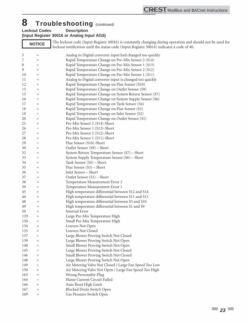
Lockout Codes Description(Input Register 30016 or Analog Input AI15)
5 = Analog to Digital converter input had changed too quickly7 = Rapid Temperature Change on Pre-Mix Sensor 2 (S14)8 = Rapid Temperature Change on Pre-Mix Sensor 1 (S13)9 = Rapid Temperature Change on Pre-Mix Sensor 2 (S12)10 = Rapid Temperature Change on Pre-Mix Sensor 1 (S11)11 = Analog to Digital converter input is changed too quickly12 = Rapid Temperature Change on Flue Sensor (S10)13 = Rapid Temperature Change on Outlet Sensor (S9)15 = Rapid Temperature Change on System Return Sensor (S7)16 = Rapid Temperature Change on System Supply Sensor (S6)17 = Rapid Temperature Change on Tank Sensor (S4)18 = Rapid Temperature Change on Flue Sensor (S3)19 = Rapid Temperature Change on Inlet Sensor (S2)20 = Rapid Temperature Change on Outlet Sensor (S1) 25 = Pre-Mix Sensor 2 (S14)-Short 26 = Pre-Mix Sensor 1 (S13)-Short27 = Pre-Mix Sensor 2 (S12)-Short 28 = Pre-Mix Sensor 1 (S11)-Short29 = Flue Sensor (S10)-Short30 = Outlet Sensor (S9) – Short32 = System Return Temperature Sensor (S7) – Short33 = System Supply Temperature Sensor (S6) – Short34 = Tank Sensor (S4) – Short35 = Flue Sensor (S3) – Short36 = Inlet Sensor – Short37 = Outlet Sensor (S1) – Short38 = Temperature Measurement Error 239 = Temperature Measurement Error 145 = High temperature differential between S12 and S14 46 = High temperature differential between S11 and S1348 = High temperature differential between S3 and S1049 = High temperature differential between S1 and S950 = Internal Error129 = Large Pre-Mix Temperature High130 = Small Pre-Mix Temperature High134 = Louvers Not Open135 = Louvers Not Closed137 = Large Blower Proving Switch Not Closed139 = Large Blower Proving Switch Not Open140 = Small Blower Proving Switch Not Open145 = Large Blower Proving Switch Not Closed146 = Small Blower Proving Switch Not Closed148 = Large Blower Proving Switch Not Open149 = Air Metering Valve Not Closed / Large Fan Speed Too Low150 = Air Metering Valve Not Open / Large Fan Speed Too High163 = Wrong Personality Plug164 = Flame Current Circuit Failed 166 = Auto Reset High Limit167 = Blocked Drain Switch Open169 = Gas Pressure Switch Open
8 Troubleshooting (continued)
The lockout code (Input Register 30016) is constantly changing during operation and should not be used for lockout notifi cation until the status code (Input Register 30014) indicates a code of 40.
NOTICE
ModBus and BACnet InstructionsM
24
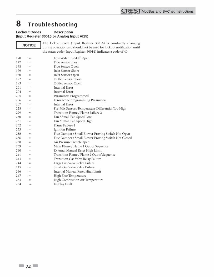
Lockout Codes Description(Input Register 30016 or Analog Input AI15)
170 = Low Water Cut-Off Open177 = Flue Sensor Short178 = Flue Sensor Open179 = Inlet Sensor Short180 = Inlet Sensor Open192 = Outlet Sensor Short193 = Outlet Sensor Open201 = Internal Error204 = Internal Error205 = Parameters Programmed206 = Error while programming Parameters207 = Internal Error228 = Pre-Mix Sensors Temperature Differential Too High229 = Transition Flame / Flame Failure 2230 = Fan / Small Fan Speed Low231 = Fan / Small Fan Speed High232 = Flame Failure 1233 = Ignition Failure235 = Flue Damper / Small Blower Proving Switch Not Open236 = Flue Damper / Small Blower Proving Switch Not Closed238 = Air Pressure Switch Open239 = Main Flame / Flame 1 Out of Sequence 240 = External Manual Reset High Limit241 = Transition Flame / Flame 2 Out of Sequence243 = Transition Gas Valve Relay Failure244 = Large Gas Valve Relay Failure245 = Small Gas Valve Relay Failure246 = Internal Manual Reset High Limit247 = High Flue Temperature253 = High Combustion Air Temperature254 = Display Fault
8 Troubleshooting
The lockout code (Input Register 30016) is constantly changing during operation and should not be used for lockout notifi cation until the status code (Input Register 30014) indicates a code of 40.
NOTICE
ModBus and BACnet InstructionsM
25
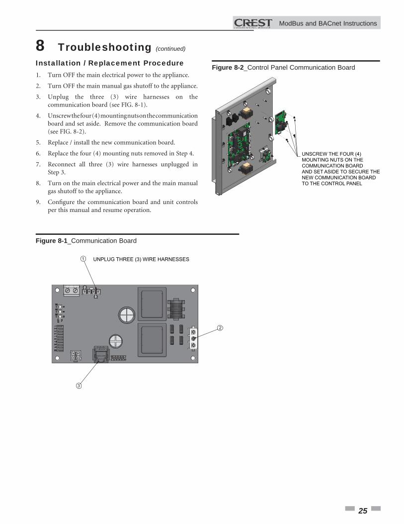
8 Troubleshooting (continued)
Installation / Replacement Procedure
1
3
2
UNPLUG THREE (3) WIRE HARNESSES
Figure 8-1_Communication Board
1. Turn OFF the main electrical power to the appliance.
2. Turn OFF the main manual gas shutoff to the appliance.
3. Unplug the three (3) wire harnesses on the communication board (see FIG. 8-1).
4. Unscrew the four (4) mounting nuts on the communication board and set aside. Remove the communication board (see FIG. 8-2).
5. Replace / install the new communication board.
6. Replace the four (4) mounting nuts removed in Step 4.
7. Reconnect all three (3) wire harnesses unplugged in Step 3.
8. Turn on the main electrical power and the main manual gas shutoff to the appliance.
9. Confi gure the communication board and unit controls per this manual and resume operation.
UNSCREW THE FOUR (4)MOUNTING NUTS ON THECOMMUNICATION BOARDAND SET ASIDE TO SECURE THENEW COMMUNICATION BOARDTO THE CONTROL PANEL
Figure 8-2_Control Panel Communication Board
ModBus and BACnet Instructions
26
9 Diagrams
ModBus and BACnet InstructionsM
JUNCTION BOX
TERMINAL STRIP120V SUPPLY "L"
TERMINAL STRIP120V SUPPLY "N"
120VAC NEUTRAL
INTEGRATED CONTROL
ON/OFFSWITCH
F2
3.15 A
F4
5.0 A SYSTEM PUMPRELAY
BOILER PUMPRELAY
DHW PUMPRELAY
X1-1
X1-2
X1-4
X1-8
X2-4SMALL BLOWER
RELAY
LARGE BLOWERRELAY
SMALL GASVALVE RELAY
LARGE GASVALVE RELAY
X1-6
X10-1 X10-2
X10-3
SMALL GASVALVE RELAY
LARGE GASVALVE RELAY X10-6
X10-5
X10-4
GASVALVE
(LARGE) GASVALVE
(SMALL)
TERMINAL STRIP
SYSTEM PUMPCONTACTOR
BOLIER PUMPCONTACTOR
DHW PUMPCONTACTOR
BLOWERRELAY
BLOWER
X6-10
X13-4
X6-1
X2-5
21
3
MODBUSX1-1 X1-2
X1-3FLUE DAMPER
TRANSFORMER
M1 2
3
24VTRANSFORMER
FLUE DAMPER
X6-3
X1-12
X1-3
LWCOBOARD
TESTSWITCH
LWCOPROBE
LWCO RESET
J3-6
J3-3
J2-1
J2-2
J3-5
J3-2
J3-4
X6-5
X6-15
X6-12
X13-1
X6-6
X3-3
X3-4
X3-1
X3-2
X6-11
X6-2
X6-14
INTEGRATEDCONTROL
GPS1 GPS2
BLOCKED FLUESWITCH
BLOCKED DRAINSWITCH
123456789
10111213141516
ALARMCONTACTS
RUN-TIMECONTACTS
TANKTHERMOSTAT
LOUVERPROVING
AUXSWITCH 1
AUXSWITCH 2
ENABLE R W
SMALLCONNECTION BOARD
CN1-4
CN1-5
CN1-6
CN1-12
CN1-10
X6-13
X6-4
CN1-11
CN1-9
CN1-8
CN1-2
CN1-3
HIGH LIMITSWITCH
X1-3
X1-7
X1-10
X2-3
FLAMESENSE 2
FLAMESENSE 1
SPARKGENERATOR
SPARKROD
171819202122232425262728293031323334353637383940
SHIELD
SHIELD
A
BMODBUSOPTION
+-
-+
RATEOUT
BOILERPUMP OUT
SYSTEM RETURNSENSOR
SYSTEM SUPPLYSENSOR
0-10V
0-10V
TANKSENSOR
OUTDOORSENSOR+
+-
-
0-10V
0-10V
BMSIN
SYSTEMPUMP IN
SHIELD
SHIELD
A
BCASCADE
LARGECONNECTION BOARD
CN6-1
CN3-6
CN3-7
CN3-14
CN3-13
CN3-11
CN3-9
CN3-8
CN3-1
CN3-2
CN3-3
CN3-4
CN6-2
CN6-3
CN3-10
CN3-12
MODBUSBOARD
X4-1
X4-2
X4-3
X6-3
X6-1
X6-2
X8-20
X8-10
X7-8
X8-13
X8-14
X8-12
INTEGRATEDCONTROL
CN3-4X8-15
X7-7
X8-11
X8-6
X8-16
X8-7
X8-17
X8-1
-T
-T
-T
-T
-T
-T
-T
INLET SENSOR
OUTLET SENSOR (S9)
OUTLET SENSOR (S1)
FLUE SENSOR
FLUE SENSOR (S10)
PRE-MIX SENSOR 1 (S11)
PRE-MIX SENSOR 1 (S13)
X8-3
X8-8
X8-2
X8-4
X8-9
X7-1
X7-5
GROUND
X6-18
X6-9
X6-17
X6-8
1
4
2
5
BLOWER
1.5A EACH MAX
X11
CN3CN1
DU941
LCD DISPLAY
X4
RIBBON CABLE
X5-1
X5-7
X5-2
X5-8
X5-3
X5-9
X5-4
X5-10
X5-5
X5-41
X5-6
X5-12
BOX DEPICTSOPTIONAL ITEMS
BOX DEPICTSDUAL SENSOR
SINGLE HOUSING
HIGH VOLTAGE
LOW VOLTAGE120 VAC
Notes:1. All wiring must be installed in accordance with: local, state, provincial and national code requirements per either N.E.C. in USA orC.S.A. in Canada.2. If any original equipment wire as supplied with the appliance must be replaced, it must be replaced with wire having same wire gauge(AWG) and rated for a minimum of 105°C. Exceptions : Replacement high voltage spark lead and ribbon cables must be purchasedfrom the factory. Use of a non-approved spark lead or ribbon cables can lead to operational problems which could result innon-repairable damage to the integrated controller or other components.3. Actual connector block locations may vary from those shown on diagrams. Refer to actual components for proper connector blocklocations when using diagrams to troubleshoot unit.
USBINTERFACE
"X5"BLOCK WIRING
IS MODEL DEPENDANT
X8-1
X8-5
LADDER DIAGRAMLBL20445 REV B
X12-4
GASTRANSITION
VALVEX12-1
X12-5
X12-2
AIR VALVEPRESS. SWITCH
24 VAC LOUVERRELAY COIL
AIR VALVE
M
X6-13
X6-16
CN1-7
CN1-1
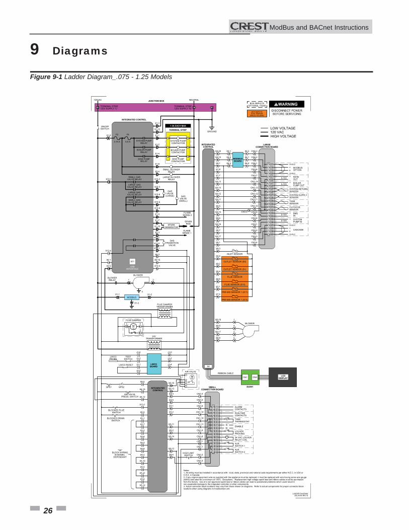
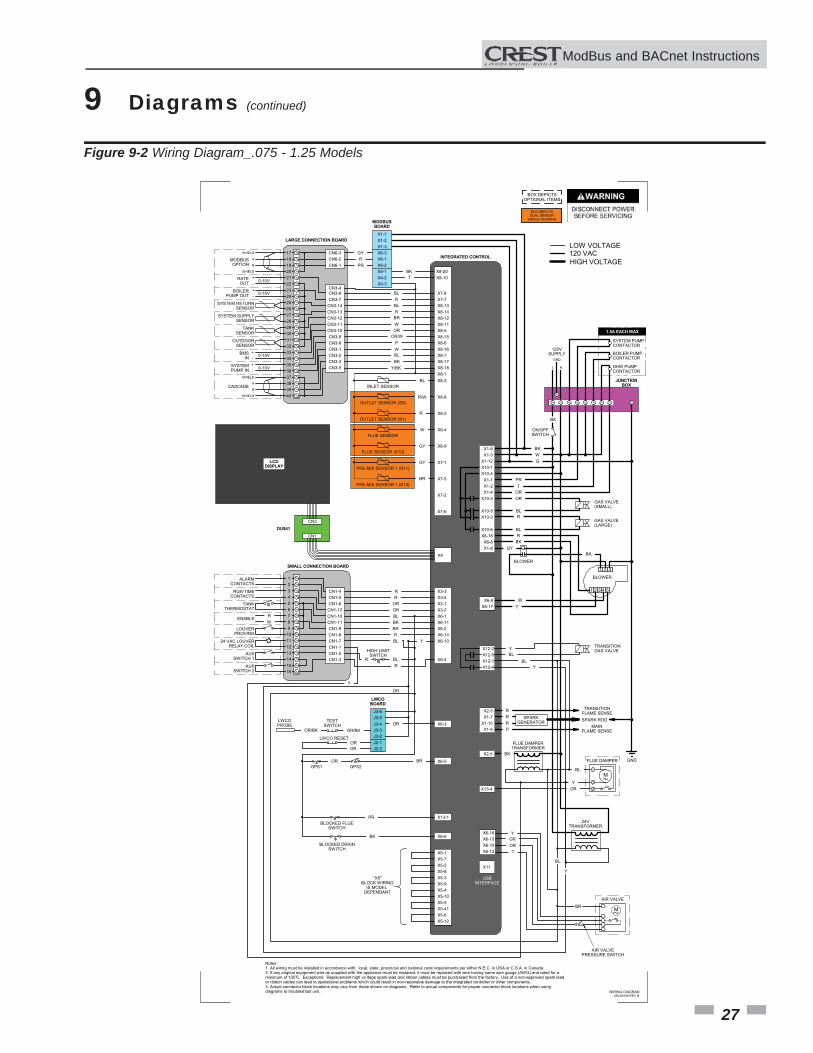
Figure 9-1 Ladder Diagram_.075 - 1.25 Models
27
9 Diagrams (continued)
ModBus and BACnet InstructionsM
-T
-T
-T
-T
-T
-T
-T
2 31
1 2 4 53
M1
2
3
Notes:1. All wiring must be installed in accordance with: local, state, provincial and national code requirements per either N.E.C. in USA or C.S.A. in Canada.2. If any original equipment wire as supplied with the appliance must be replaced, it must be replaced with wire having same wire gauge (AWG) and rated for aminimum of 105°C. Exceptions: Replacement high vo ltage spark lead and ribbon cables must be purchased from the factory. Use of a non-approved spark leador ribbon cables can lead to operational problems which could result in non-repairable damage to the integrated controller or other components.3. Actual connector block locations may vary from those shown on diagrams. Refer to actual components for proper connector block locations when usingdiagrams to troubleshoot unit. WIRING DIAGRAM
BOX DEPICTSOPTIONAL ITEMS
BOX DEPICTSDUAL SENSOR
SINGLE HOUSING
123456789
10111213141516
CN1-12
CN1-5
CN1-10CN1-11
CN1-6
CN1-9CN1-8CN1-7CN1-1CN1-2CN1-3
CN1-4
17
CN3-6
CN6-2
CN3-7CN3-14
CN6-1
CN3-13CN3-12CN3-11CN3-10CN3-9CN3-8
CN6-31819202122232425262728293031323334353637383940
CN3-1CN3-2
CN3-5CN3-3
X3-2
X3-4
X6-1X6-11
X3-1
X6-2X6-14X6-10
X6-4
X3-3
X7-8X7-7
X8-14X8-13
X8-12X8-11
X8-15X8-5
X8-6X8-16X8-7X8-17X8-18X8-1
ALARMCONTACTS
RUN-TIMECONTACTS
TANKTHERMOSTAT
LOUVERPROVING
AUXSWITCH 1
AUXSWITCH 2
SHIELD
SHIELD
A
BMODBUSOPTION
+-
-+
RATEOUT
BOILERPUMP OUT
SYSTEM RETURNSENSOR
SYSTEM SUPPLYSENSOR
0-10V
0-10V
TANKSENSOR
OUTDOORSENSOR
+
+-
-
0-10V
0-10V
BMSIN
SYSTEMPUMP IN
SHIELD
SHIELD
A
BCASCADE
R R RO RO LB KB RB
R Y
HIGH LIMITSWITCH R
R
X6-1X6-2
X6-3 YG R RP
MODBUSBOARD
LB R LB R RB W RO
OR/W P W LB KB
J3-5J3-4
J3-6
LWCOBOARD
J3-3J3-2J2-1J2-2
X6-3 ROOR/BK OR/BK
TESTSWITCH
LWCOPROBE
RO RO
LWCO RESET
X6-5GPS1 GPS2
RB RO
X13-1BLOCKED FLUE
SWITCH
RP
X6-6
BLOCKED DRAINSWITCH
KB
ENABLE
X8-3
X8-8
X8-2
X8-4
X8-9
X7-1
X7-5
X7-2
X7-6
INLET SENSOR
OUTLET SENSOR (S9)
OUTLET SENSOR (S1)
FLUE SENSOR
FLUE SENSOR (S10)
PRE-MIX SENSOR 1 (S11)
PRE-MIX SENSOR 1 (S13)
R W
X4-1X4-2X4-3
X8-20X8-10
X5-8
X5-7
X5-3X5-9
X5-2
X5-4X5-10X5-5X5-41X5-6X5-12
X5-1
"X5"BLOCK WIRING
IS MODEL DEPENDANT
KB T
LB
W/R
R
W
YG
YG
RB
X10-1
X1-3
X10-4X1-1
X1-12
X1-2X1-4
X10-2
X10-5X10-3
X10-6
X1-6
L N
GND
120VSUPPLY
ON/OFFSWITCH
GND
GAS VALVE(SMALL)
GAS VALVE(LARGE)
KB W
RP T RO RO
LB R
LBX6-18
X6-8X1-8
G
X6-9X6-17
BLOWER
BLOWER
R KB
YG
W T
KB
X2-3X1-7
X1-10X1-5
TRANSITIONFLAME SENSE
MAINFLAME SENSE
SPARKGENERATOR SPARK ROD
X2-5
FLUE DAMPERTRANSFORMER
X13-4
FLUE DAMPER
24VTRANSFORMER
LB
R R R P
KB
LB
Y RO
BL
Y
BK
X1-2X1-3
X1-1
INTEGRATED CONTROL
LARGE CONNECTION BOARD
SMALL CONNECTION BOARD
JUNCTIONBOX
X11
X4
CN3
CN1
DU941
USBINTERFACE
LCD DISPLAY
BOILER PUMPCONTACTOR
SYSTEM PUMPCONTACTOR
DHW PUMPCONTACTOR
HIGH VOLTAGE
LOW VOLTAGE120 VAC
1.5A EACH MAX
KB/Y
CN3-4
LBL20446 REV B
X12-2X12-5X12-1X12-4
TRANSITIONGAS VALVE Y
LB
Y LB
RO
AIR VALVEPRESSURE SWITCH
24 VAC LOUVERRELAY COIL
X6-16X6-13X6-15X6-12
Y
T RO
AIR VALVE
M
RO
BLBL
BR
LB
Y
Figure 9-2 Wiring Diagram_.075 - 1.25 Models
28
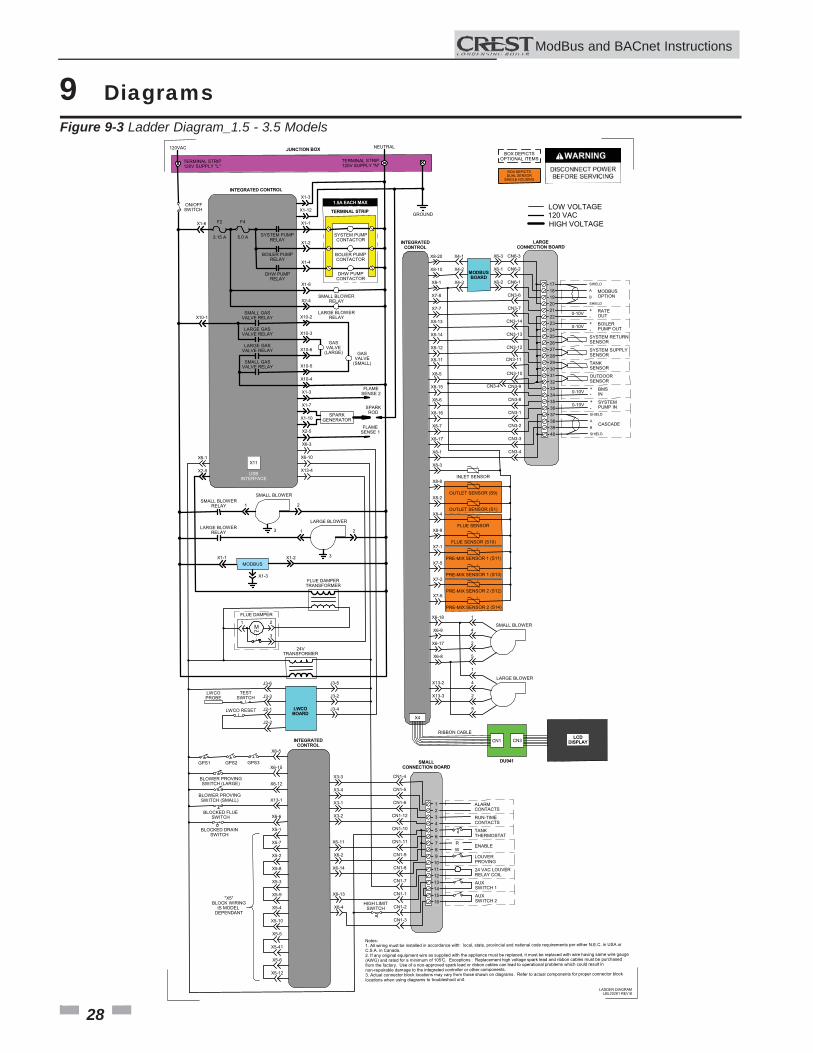
9 Diagrams Figure 9-3 Ladder Diagram_1.5 - 3.5 Models
JUNCTION BOX
TERMINAL STRIP120V SUPPLY "L"
TERMINAL STRIP120V SUPPLY "N"
120VAC NEUTRAL
INTEGRATED CONTROL
ON/OFFSWITCH
F2
3.15 A
F4
5.0 A SYSTEM PUMPRELAY
BOILER PUMPRELAY
DHW PUMPRELAY
X1-1
X1-2
X1-4
X1-8
X2-4SMALL BLOWER
RELAY
LARGE BLOWERRELAY
SMALL GASVALVE RELAY
LARGE GASVALVE RELAY
X1-6
X10-1 X10-2
X10-3
SMALL GASVALVE RELAY
LARGE GASVALVE RELAY X10-6
X10-5
X10-4
GASVALVE
(LARGE) GASVALVE
(SMALL)
TERMINAL STRIP
SYSTEM PUMPCONTACTOR
BOLIER PUMPCONTACTOR
DHW PUMPCONTACTOR
SMALL BLOWERRELAY
LARGE BLOWERRELAY
SMALL BLOWER
LARGE BLOWER
X6-10
X13-4
X6-1
X2-5
21
3 21
3
MODBUSX1-1 X1-2
X1-3FLUE DAMPER
TRANSFORMER
M1 2
3
24VTRANSFORMER
FLUE DAMPER
X6-3
X1-12
X1-3
LWCOBOARD
TESTSWITCH
LWCOPROBE
LWCO RESET
J3-6
J3-3
J2-1
J2-2
J3-5
J3-2
J3-4
X6-5
X6-15
X6-12
X13-1
X6-6
X3-3
X3-4
X3-1
X3-2
X6-11
X6-2
X6-14
INTEGRATEDCONTROL
GPS1 GPS2 GPS3
BLOWER PROVINGSWITCH (LARGE)
BLOWER PROVINGSWITCH (SMALL)
BLOCKED FLUESWITCH
BLOCKED DRAINSWITCH
12345678910111213141516
ALARMCONTACTS
RUN-TIMECONTACTS
TANKTHERMOSTAT
LOUVERPROVING
24 VAC LOUVERRELAY COIL
AUXSWITCH 1
AUXSWITCH 2
ENABLE R W
SMALLCONNECTION BOARD
CN1-4
CN1-5
CN1-6
CN1-12
CN1-10
X6-13
X6-4
CN1-11
CN1-9
CN1-8
CN1-7
CN1-1
CN1-2
CN1-3
HIGH LIMITSWITCH
X1-3
X1-7
X1-10
X2-5
FLAMESENSE 2
FLAMESENSE 1
SPARKGENERATOR
SPARKROD
171819202122232425262728293031323334353637383940
SHIELD
SHIELD
A
BMODBUSOPTION
+-
-+
RATEOUT
BOILERPUMP OUT
SYSTEM RETURNSENSOR
SYSTEM SUPPLYSENSOR
0-10V
0-10V
TANKSENSOR
OUTDOORSENSOR+
+-
-
0-10V
0-10V
BMSIN
SYSTEMPUMP IN
SHIELD
SHIELD
A
BCASCADE
LARGECONNECTION BOARD
CN6-1
CN3-6
CN3-7
CN3-14
CN3-13
CN3-11
CN3-9
CN3-8
CN3-1
CN3-2
CN3-3
CN3-4
CN6-2
CN6-3
CN3-10
CN3-12
MODBUSBOARD
X4-1
X4-2
X4-3
X6-3
X6-1
X6-2
X8-20
X8-10
X7-8
X8-13
X8-14
X8-12
INTEGRATEDCONTROL
CN3-4X8-15
X7-7
X8-11
X8-6
X8-16
X8-7
X8-17
X8-1
-T
-T
-T
-T
-T
-T
-T
-T
-T
INLET SENSOR
OUTLET SENSOR (S9)
OUTLET SENSOR (S1)
FLUE SENSOR
FLUE SENSOR (S10)
PRE-MIX SENSOR 1 (S11)
PRE-MIX SENSOR 1 (S13)
PRE-MIX SENSOR 2 (S12)
PRE-MIX SENSOR 2 (S14)
X8-3
X8-8
X8-2
X8-4
X8-9
X7-1
X7-5
X7-2
X7-6
GROUND
X6-18
X6-9
X6-17
X6-8
X13-2
X13-3
1
4
2
5
1
4
2
5
SMALL BLOWER
LARGE BLOWER
1.5A EACH MAX
X11
CN3CN1
DU941
LCD DISPLAY
X4
RIBBON CABLE
X5-1
X5-7
X5-2
X5-8
X5-3
X5-9
X5-4
X5-10
X5-5
X5-41
X5-6
X5-12
BOX DEPICTSOPTIONAL ITEMS
BOX DEPICTSDUAL SENSOR
SINGLE HOUSING
HIGH VOLTAGE
LOW VOLTAGE120 VAC
Notes:1. All wiring must be installed in accordance with: local, state, provincial and national code requirements per either N.E.C. in USA orC.S.A. in Canada.2. If any original equipment wire as supplied with the appliance must be replaced, it must be replaced with wire having same wire gauge(AWG) and rated for a minimum of 105°C. Exceptions : Replacement high voltage spark lead and ribbon cables must be purchasedfrom the factory. Use of a non-approved spark lead or ribbon cables can lead to operational problems which could result innon-repairable damage to the integrated controller or other components.3. Actual connector block locations may vary from those shown on diagrams. Refer to actual components for proper connector blocklocations when using diagrams to troubleshoot unit.
USBINTERFACE
"X5"BLOCK WIRING
IS MODEL DEPENDANT
X8-1
X8-5
LADDER DIAGRAMLBL20281 REV B
ModBus and BACnet InstructionsM
9 Diagrams (continued)
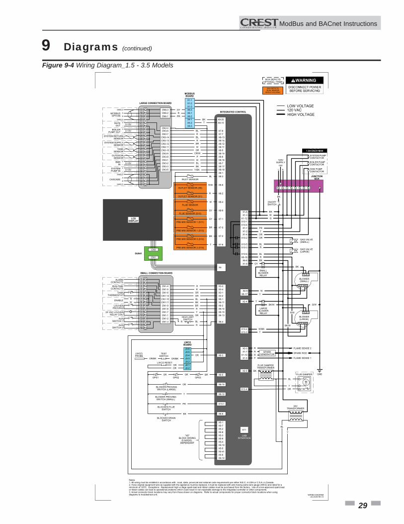
Figure 9-4 Wiring Diagram_1.5 - 3.5 Models
-T
-T
-T
-T
-T
-T
-T
-T
-T
2 31
1 2 4 53
2 31
1 2 4 53
M1
2
3
Notes:1. All wiring must be installed in accordance with: local, state, provincial and national code requirements per either N.E.C. in USA or C.S.A. in Canada.2. If any original equipment wire as supplied with the appliance must be replaced, it must be replaced with wire having same wire gauge (AWG) and rated for aminimum of 105°C. Exceptions: Replacement high vo ltage spark lead and ribbon cables must be purchased from the factory. Use of a non-approved spark leador ribbon cables can lead to operational problems which could result in non-repairable damage to the integrated controller or other components.3. Actual connector block locations may vary from those shown on diagrams. Refer to actual components for proper connector block locations when usingdiagrams to troubleshoot unit. WIRING DIAGRAM
BOX DEPICTSOPTIONAL ITEMS
BOX DEPICTSDUAL SENSOR
SINGLE HOUSING
123456789
10111213141516
CN1-12
CN1-5
CN1-10CN1-11
CN1-6
CN1-9CN1-8CN1-7CN1-1CN1-2CN1-3
CN1-4
17
CN3-6
CN6-2
CN3-7CN3-14
CN6-1
CN3-13CN3-12CN3-11CN3-10CN3-9CN3-8
CN6-31819202122232425262728293031323334353637383940
CN3-1CN3-2
CN3-5CN3-3
X3-2
X3-4
X6-1X6-11
X3-1
X6-2X6-14X6-10X6-13
X6-4
X3-3
X7-8X7-7
X8-14X8-13
X8-12X8-11
X8-15X8-5
X8-6X8-16X8-7X8-17X8-18X8-1
ALARMCONTACTS
RUN-TIMECONTACTS
TANKTHERMOSTAT
LOUVERPROVING
24 VAC LOUVERRELAY COIL
AUXSWITCH 1
AUXSWITCH 2
SHIELD
SHIELD
A
BMODBUSOPTION
+-
-+
RATEOUT
BOILERPUMP OUT
SYSTEM RETURNSENSOR
SYSTEM SUPPLYSENSOR
0-10V
0-10V
TANKSENSOR
OUTDOORSENSOR
+
+-
-
0-10V
0-10V
BMSIN
SYSTEMPUMP IN
SHIELD
SHIELD
A
BCASCADE
R R RO RO LB KB RB
R Y RO
HIGH LIMITSWITCH R
R
X6-1X6-2
X6-3 YG R RP
MODBUSBOARD
LB R LB R RB W RO
OR/W P W LB KB
J3-5J3-4
J3-6
LWCOBOARD
J3-3J3-2J2-1J2-2
X6-3 ROOR/BK OR/BK
TESTSWITCH
LWCOPROBE
RO RO
LWCO RESET
X6-5GPS1 GPS2 GPS3
RB RO RO
X6-15BLOWER PROVINGSWITCH (LARGE)
RO
X6-12BLOWER PROVINGSWITCH (SMALL)
T
X13-1BLOCKED FLUE
SWITCH
RP
X6-6
BLOCKED DRAINSWITCH
KB
ENABLE
X8-3
X8-8
X8-2
X8-4
X8-9
X7-1
X7-5
X7-2
X7-6
INLET SENSOR
OUTLET SENSOR (S9)
OUTLET SENSOR (S1)
FLUE SENSOR
FLUE SENSOR (S10)
PRE-MIX SENSOR 1 (S11)
PRE-MIX SENSOR 1 (S13)
PRE-MIX SENSOR 2 (S12)
PRE-MIX SENSOR 2 (S14)
R W
X4-1X4-2X4-3
X8-20X8-10
X5-8
X5-7
X5-3X5-9
X5-2
X5-4X5-10X5-5X5-41X5-6X5-12
X5-1
"X5"BLOCK WIRING
IS MODEL DEPENDANT
KB T
LB
W/R
R
W
YG
YG
RB
T
X10-1
X1-3
X10-4X1-1
X1-12
X1-2X1-4
X10-2
X10-5X10-3
X10-6
X1-6
L N
GND
120VSUPPLY
ON/OFFSWITCH
GND
GAS VALVE(SMALL)
GAS VALVE(LARGE)
KB W
RP T RO RO
LB R
LBX6-18
X6-8X1-8
G
X6-9X6-17
SMALLBLOWER
RELAY
LARGEBLOWER
RELAY
X2-4
X13-2X13-3
BLOWER(SMALL)
BLOWER(LARGE)
R KB
YG
W T
T
KB/W T
KB
BK/W W/G
R/W
BK/W
X2-3X1-7
X1-10X1-5
FLAME SENSE 2
FLAME SENSE 1
SPARKGENERATOR SPARK ROD
X2-5
FLUE DAMPERTRANSFORMER
X13-4
FLUE DAMPER
24VTRANSFORMER
LB
R R R P
KB
LB
Y RO
BL
Y
BK
X1-2X1-3
X1-1
INTEGRATED CONTROL
LARGE CONNECTION BOARD
SMALL CONNECTION BOARD
JUNCTIONBOX
X11
X4
CN3
CN1
DU941
USBINTERFACE
LCD DISPLAY
BOILER PUMPCONTACTOR
SYSTEM PUMPCONTACTOR
DHW PUMPCONTACTOR
KB
HIGH VOLTAGE
LOW VOLTAGE120 VAC
1.5A EACH MAX
KB/Y
CN3-4
LBL20280 REV B
ModBus and BACnet InstructionsM
29
30
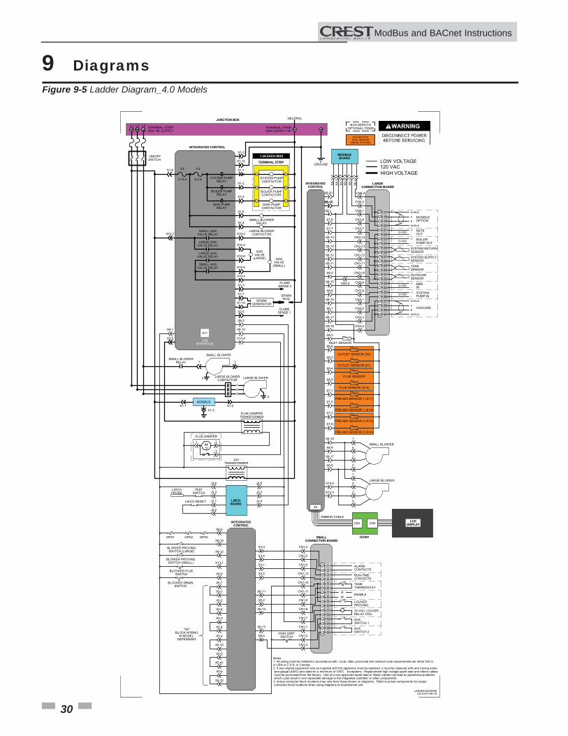
9 Diagrams Figure 9-5 Ladder Diagram_4.0 Models
ModBus and BACnet InstructionsM
JUNCTION BOX
TERMINAL STRIP208V 3� SUPPLY
TERMINAL STRIP208V SUPPLY "N"
NEUTRAL
INTEGRATED CONTROL
ON/OFFSWITCH
F2
3.15 A
F4
5.0 A SYSTEM PUMPRELAY
BOILER PUMPRELAY
DHW PUMPRELAY
X1-1
X1-2
X1-4
X1-8
X2-4SMALL BLOWER
RELAY
LARGE BLOWERCONTACTOR
SMALL GASVALVE RELAY
LARGE GASVALVE RELAY
X1-6
X10-1 X10-2
X10-3
SMALL GASVALVE RELAY
LARGE GASVALVE RELAY X10-6
X10-5
X10-4
GASVALVE
(LARGE) GASVALVE
(SMALL)
TERMINAL STRIP
SYSTEM PUMPCONTACTOR
BOLIER PUMPCONTACTOR
DHW PUMPCONTACTOR
SMALL BLOWERRELAY
LARGE BLOWERCONTACTOR
SMALL BLOWER
LARGE BLOWER
X6-10
X13-4
X6-1
X2-5
21
3
MODBUSX1-1 X1-2
X1-3FLUE DAMPER
TRANSFORMER
M1 2
3
24VTRANSFORMER
FLUE DAMPER
X6-3
X1-12
X1-3
LWCOBOARD
TESTSWITCH
LWCOPROBE
LWCO RESET
J3-6
J3-3
J2-1
J2-2
J3-5
J3-2
J3-4
X6-5
X6-15
X6-12
X13-1
X6-6
X3-3
X3-4
X3-1
X3-2
X6-11
X6-2
X6-14
INTEGRATEDCONTROL
GPS1 GPS2 GPS3
BLOWER PROVINGSWITCH (LARGE)
BLOWER PROVINGSWITCH (SMALL)
BLOCKED FLUESWITCH
BLOCKED DRAINSWITCH
123456789
10111213141516
ALARMCONTACTS
RUN-TIMECONTACTS
TANKTHERMOSTAT
LOUVERPROVING
24 VAC LOUVERRELAY COIL
AUXSWITCH 1
AUXSWITCH 2
ENABLE R W
SMALLCONNECTION BOARD
CN1-4
CN1-5
CN1-6
CN1-12
CN1-10
X6-13
X6-4
CN1-11
CN1-9
CN1-8
CN1-7
CN1-1
CN1-2
CN1-3
HIGH LIMITSWITCH
X1-3
X1-7
X1-10
X2-5
FLAMESENSE 2
FLAMESENSE 1
SPARKGENERATOR
SPARKROD
171819202122232425262728293031323334353637383940
SHIELD
SHIELD
A
BMODBUSOPTION
+-
-+
RATEOUT
BOILERPUMP OUT
SYSTEM RETURNSENSOR
SYSTEM SUPPLYSENSOR
0-10V
0-10V
TANKSENSOR
OUTDOORSENSOR+
+-
-
0-10V
0-10V
BMSIN
SYSTEMPUMP IN
SHIELD
SHIELD
A
BCASCADE
LARGECONNECTION BOARD
CN6-1
CN3-6
CN3-7
CN3-14
CN3-13
CN3-11
CN3-9
CN3-8
CN3-1
CN3-2
CN3-3
CN3-4
CN6-2
CN6-3
CN3-10
CN3-12
MODBUSBOARD
X4-1
X4-2
X4-3
X6-3
X6-1
X6-2
X8-20
X8-10
X7-8
X8-13
X8-14
X8-12
INTEGRATEDCONTROL
X8-5
X8-15
X7-7
X8-11
X8-6
X8-16
X8-7
X8-17
X8-18
-T
-T
-T
-T
-T
-T
-T
-T
-T
INLET SENSOR
OUTLET SENSOR (S9)
OUTLET SENSOR (S1)
FLUE SENSOR
FLUE SENSOR (S10)
PRE-MIX SENSOR 1 (S11)
PRE-MIX SENSOR 1 (S13)
PRE-MIX SENSOR 2 (S12)
PRE-MIX SENSOR 2 (S14)
X8-3
X8-8
X8-2
X8-4
X8-9
X7-1
X7-5
X7-2
X7-6
GROUND
X6-18
X6-9
X6-17
X6-8
X13-2
X13-3
1
4
2
5
1
4
2
5
SMALL BLOWER
LARGE BLOWER
1.5A EACH MAX
X11
CN3CN1
DU941
LCD DISPLAY
X4
RIBBON CABLE
X5-1
X5-7
X5-2
X5-8
X5-3
X5-9
X5-4
X5-10
X5-5
X5-41
X5-6
X5-12
BOX DEPICTSOPTIONAL ITEMS
BOX DEPICTSDUAL SENSOR
SINGLE HOUSING
HIGH VOLTAGE
LOW VOLTAGE120 VAC
Notes:1. All wiring must be installed in accordance with: local, state, provincial and national code requirements per either N.E.C.in USA or C.S.A. in Canada.2. If any original equipment wire as supplied with the appliance must be replaced, it must be replaced with wire having same wire gauge (AWG) and rated for a minimum of 105°C. Exceptions: Replacement high voltage spark lead and ribbon cables must be purchased from the factory. Use of a non-approved spark lead or ribbon cables can lead to operational problems which could result in non-repairable damage to the integrated controller or other components.3. Actual connector block locations may vary from those shown on diagrams. Refer to actual components for proper connector block locations when using diagrams to troubleshoot unit.
USBINTERFACE
"X5"BLOCK WIRING
IS MODEL DEPENDANT
L1 L2 L3
123
4
LADDER DIAGRAMLBL20270 REV B
X8-10
X8-1
CN3-4
31
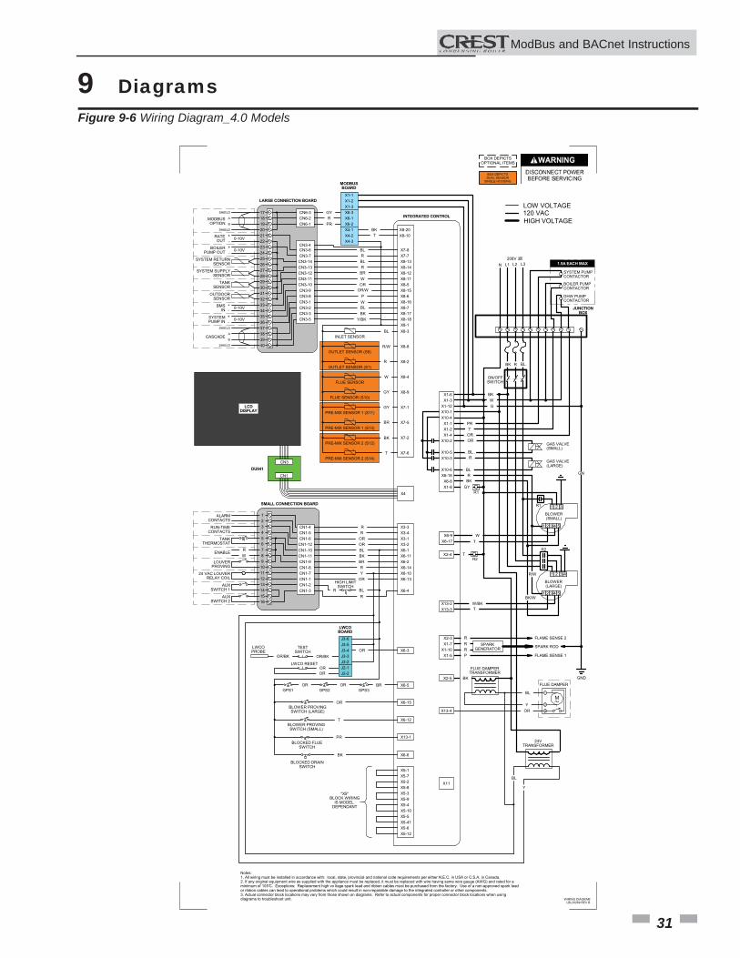
9 Diagrams Figure 9-6 Wiring Diagram_4.0 Models
ModBus and BACnet InstructionsM
-T
-T
-T
-T
-T
-T
-T
-T
-T
1 32
1 2 4 53
M1
2
3
Notes:1. All wiring must be installed in accordance with: local, state, provincial and national code requirements per either N.E.C. in USA or C.S.A. in Canada.2. If any original equipment wire as supplied with the appliance must be replaced, it must be replaced with wire having same wire gauge (AWG) and rated for aminimum of 105°C. Exceptions: Replacement high vo ltage spark lead and ribbon cables must be purchased from the factory. Use of a non-approved spark leador ribbon cables can lead to operational problems which could result in non-repairable damage to the integrated controller or other components.3. Actual connector block locations may vary from those shown on diagrams. Refer to actual components for proper connector block locations when usingdiagrams to troubleshoot unit.
BOX DEPICTSOPTIONAL ITEMS
BOX DEPICTSDUAL SENSOR
SINGLE HOUSING
123456789
10111213141516
CN1-12
CN1-5
CN1-10CN1-11
CN1-6
CN1-9CN1-8CN1-7CN1-1CN1-2CN1-3
CN1-4
17
CN3-6
CN6-2
CN3-7CN3-14
CN6-1
CN3-13CN3-12CN3-11CN3-10CN3-9CN3-8
CN6-31819202122232425262728293031323334353637383940
CN3-1CN3-2
CN3-5CN3-3
X3-2
X3-4
X6-1X6-11
X3-1
X6-2X6-14X6-10X6-13
X6-4
X3-3
X7-8X7-7
X8-14X8-13
X8-12X8-11
X8-15X8-5
X8-6X8-16X8-7X8-17X8-18X8-1
ALARMCONTACTS
RUN-TIMECONTACTS
TANKTHERMOSTAT
LOUVERPROVING
24 VAC LOUVERRELAY COIL
AUXSWITCH 1
AUXSWITCH 2
SHIELD
SHIELD
A
BMODBUSOPTION
+-
-+
RATEOUT
BOILERPUMP OUT
SYSTEM RETURNSENSOR
SYSTEM SUPPLYSENSOR
0-10V
0-10V
TANKSENSOR
OUTDOORSENSOR
+
+-
-
0-10V
0-10V
BMSIN
SYSTEMPUMP IN
SHIELD
SHIELD
A
BCASCADE
R R RO RO LB KB RB
R Y RO
HIGH LIMITSWITCH R
R
X6-1X6-2
X6-3 YG R RP
MODBUSBOARD
LB R LB R RB W RO
OR/W P W LB KB
Y/BK
J3-5J3-4
J3-6
LWCOBOARD
J3-3J3-2J2-1J2-2
X6-3 ROOR/BK OR/BK
TESTSWITCH
LWCOPROBE
RO RO
LWCO RESET
X6-5GPS1 GPS2 GPS3
RB RO RO
X6-15BLOWER PROVINGSWITCH (LARGE)
RO
X6-12BLOWER PROVINGSWITCH (SMALL)
T
X13-1BLOCKED FLUE
SWITCH
RP
X6-6
BLOCKED DRAINSWITCH
KB
ENABLE
X8-3
X8-8
X8-2
X8-4
X8-9
X7-1
X7-5
X7-2
X7-6
INLET SENSOR
OUTLET SENSOR (S9)
OUTLET SENSOR (S1)
FLUE SENSOR
FLUE SENSOR (S10)
PRE-MIX SENSOR 1 (S11)
PRE-MIX SENSOR 1 (S13)
PRE-MIX SENSOR 2 (S12)
PRE-MIX SENSOR 2 (S14)
R W
X4-1X4-2X4-3
X8-20X8-10
X5-8
X5-7
X5-3X5-9
X5-2
X5-4X5-10X5-5X5-41X5-6X5-12
X5-1
"X5"BLOCK WIRING
IS MODEL DEPENDANT
KB T
LB
W/R
R
W
YG
YG
RB
T
X10-1
X1-3
X10-4X1-1
X1-12
X1-2X1-4
X10-2
X10-5X10-3
X10-6
X1-6
ON/OFFSWITCH
GND
GAS VALVE(SMALL)
GAS VALVE(LARGE)
KB W
RP T
RO RO
LB R
LBX6-18
X6-8X1-8
G
X6-9X6-17
X2-4
X13-2X13-3
BLOWER(SMALL)
BLOWER(LARGE)
R KB
YG
W T
T
KB/W T
NG
R/W
BK/W
X2-3X1-7
X1-10X1-5
FLAME SENSE 2
FLAME SENSE 1
SPARKGENERATOR SPARK ROD
X2-5
FLUE DAMPERTRANSFORMER
X13-4
FLUE DAMPER
24VTRANSFORMER
LB
R R R P
KB
LB
Y RO
BL
Y
BK
X1-2X1-3
X1-1
INTEGRATED CONTROL
LARGE CONNECTION BOARD
SMALL CONNECTION BOARD
JUNCTIONBOX
X11
X4
CN3
CN1
DU941
USBINTERFACE
LCD DISPLAY
BOILER PUMPCONTACTOR
SYSTEM PUMPCONTACTOR
DHW PUMPCONTACTOR
KB
HIGH VOLTAGE
LOW VOLTAGE120 VAC
1.5A EACH MAX
WIRING DIAGRAMLBL20269 REV B
2R
R BL
1R
2R
L1 L2 L3208V 3�
R1
N
1 32
1 2 4 53
4
CN3-4
32
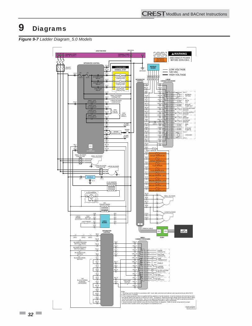
9 Diagrams Figure 9-7 Ladder Diagram_5.0 Models
ModBus and BACnet InstructionsM
JUNCTION BOX
TERMINAL STRIP208V 3� SUPPLY
TERMINAL STRIP208V SUPPLY "N"
NEUTRAL
INTEGRATED CONTROL
ON/OFFSWITCH
F2
3.15 A
F4
5.0 A SYSTEM PUMPRELAY
BOILER PUMPRELAY
DHW PUMPRELAY
X1-1
X1-2
X1-4
X1-8
X2-4SMALL BLOWER
CONTACTOR
LARGE BLOWERCONTACTOR
SMALL GASVALVE RELAY
LARGE GASVALVE RELAY
X1-6
X10-1 X10-2
X10-3
SMALL GASVALVE RELAY
LARGE GASVALVE RELAY X10-6
X10-5
X10-4
GASVALVE
(LARGE) GASVALVE
(SMALL)
TERMINAL STRIP
SYSTEM PUMPCONTACTOR
BOLIER PUMPCONTACTOR
DHW PUMPCONTACTOR
SMALL BLOWERCONTACTOR
LARGE BLOWERCONTACTOR
SMALL BLOWER
LARGE BLOWER
X6-10
X13-4
X6-1
X2-5
4
MODBUS2-1X1-1X
X1-3FLUE DAMPER
TRANSFORMER
M1 2
3
24VTRANSFORMER
FLUE DAMPER
X6-3
X1-12
X1-3
LWCOBOARD
TESTSWITCH
LWCOPROBE
LWCO RESET
J3-6
J3-3
J2-1
J2-2
J3-5
J3-2
J3-4
X6-5
X6-15
X6-12
X13-1
X6-6
X3-3
X3-4
X3-1
X3-2
X6-11
X6-2
X6-14
INTEGRATEDCONTROL
GPS1 GPS2 GPS3
BLOWER PROVINGSWITCH (LARGE)
BLOWER PROVINGSWITCH (SMALL)
BLOCKED FLUESWITCH
BLOCKED DRAINSWITCH
123456789
10111213141516
ALARMCONTACTS
RUN-TIMECONTACTS
TANKTHERMOSTAT
LOUVERPROVING
24 VAC LOUVERRELAY COIL
AUXSWITCH 1
AUXSWITCH 2
ENABLE R W
SMALLCONNECTION BOARD
CN1-4
CN1-5
CN1-6
CN1-12
CN1-10
X6-13
X6-4
CN1-11
CN1-9
CN1-8
CN1-7
CN1-1
CN1-2
CN1-3
HIGH LIMITSWITCH
X1-3
X1-7
X1-10
X2-5
FLAMESENSE 2
FLAMESENSE 1
SPARKGENERATOR
SPARKROD
171819202122232425262728293031323334353637383940
SHIELD
SHIELD
A
BMODBUSOPTION
+-
-+
RATEOUT
BOILERPUMP OUT
SYSTEM RETURNSENSOR
SYSTEM SUPPLYSENSOR
0-10V
0-10V
TANKSENSOR
OUTDOORSENSOR+
+-
-
0-10V
0-10V
BMSIN
SYSTEMPUMP IN
SHIELD
SHIELD
A
BCASCADE
LARGECONNECTION BOARD
CN6-1
CN3-6
CN3-7
CN3-14
CN3-13
CN3-11
CN3-9
CN3-8
CN3-1
CN3-2
CN3-3
CN3-4
CN6-2
CN6-3
CN3-10
CN3-12
MODBUSBOARD
X4-1
X4-2
X4-3
X6-3
X6-1
X6-2
X8-20
X8-10
X7-8
X8-13
X8-14
X8-12
INTEGRATEDCONTROL
X8-5
X8-15
X7-7
X8-11
X8-6
X8-16
X8-7
X8-17
X8-18
-T
-T
-T
-T
-T
-T
-T
-T
-T
INLET SENSOR
OUTLET SENSOR (S9)
OUTLET SENSOR (S1)
FLUE SENSOR
FLUE SENSOR (S10)
PRE-MIX SENSOR 1 (S11)
PRE-MIX SENSOR 1 (S13)
PRE-MIX SENSOR 2 (S12)
PRE-MIX SENSOR 2 (S14)
X8-3
X8-8
X8-2
X8-4
X8-9
X7-1
X7-5
X7-2
X7-6
GROUND
X6-18
X6-9
X6-17
X6-8
X13-2
X13-3
1
2
4
5
1
2
4
5
SMALL BLOWER
LARGE BLOWER
1.5A EACH MAX
X11
CN3CN1
DU941
LCD DISPLAY
X4
RIBBON CABLE
X5-1
X5-7
X5-2
X5-8
X5-3
X5-9
X5-4
X5-10
X5-5
X5-41
X5-6
X5-12
BOX DEPICTSOPTIONAL ITEMS
BOX DEPICTSDUAL SENSOR
SINGLE HOUSING
HIGH VOLTAGE
LOW VOLTAGE120 VAC
Notes:1. All wiring must be installed in accordance with: local, state, provincial and national code requirements per either N.E.C.in USA or C.S.A. in Canada.2. If any original equipment wire as supplied with the appliance must be replaced, it must be replaced with wire having same wire gauge (AWG) and rated for a minimum of 105°C. Exceptions: Replacement high voltage spark lead and ribbon cables must be purchased from the factory. Use of a non-approved spark lead or ribbon cables can lead to operational problems which could result in non-repairable damage to the integrated controller or other components.3. Actual connector block locations may vary from those shown on diagrams. Refer to actual components for proper connector block locations when using diagrams to troubleshoot unit.
USBINTERFACE
"X5"BLOCK WIRING
IS MODEL DEPENDANT
L1 L2 L3
123
4
123
LADDER DIAGRAMLBL20272 REV A
X8-1
CN3-4
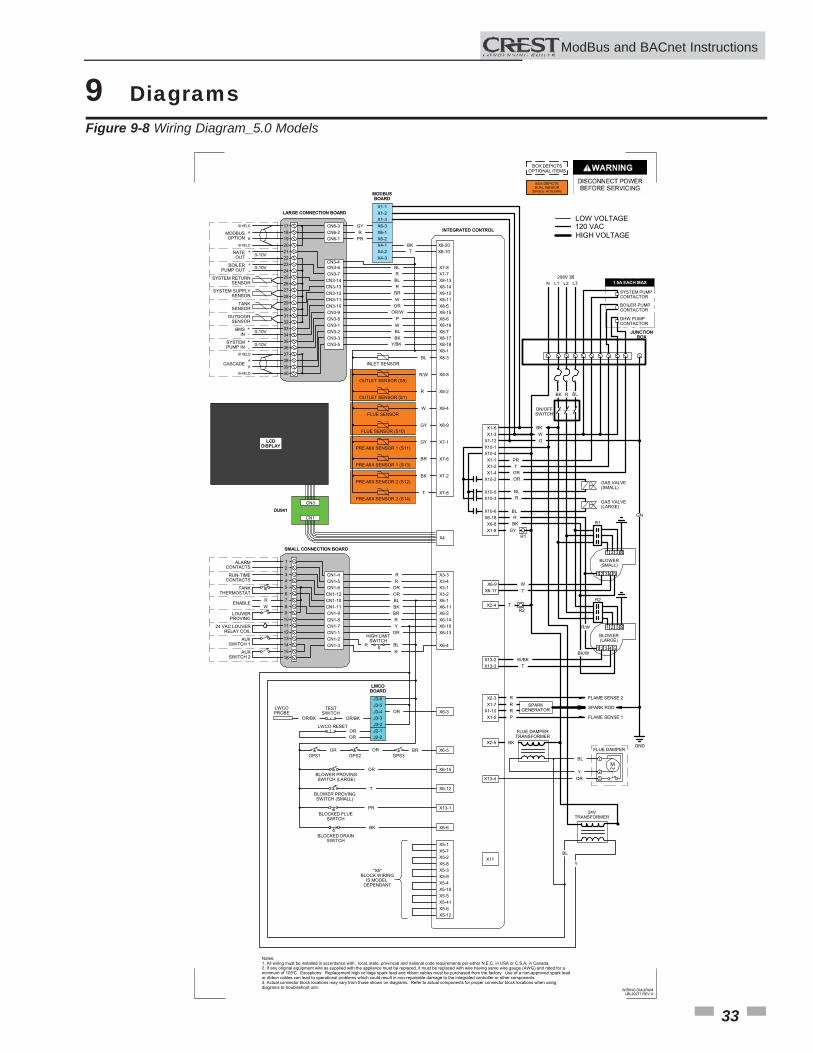
33
9 Diagrams Figure 9-8 Wiring Diagram_5.0 Models
ModBus and BACnet InstructionsM
-T
-T
-T
-T
-T
-T
-T
-T
-T
M1
2
3
Notes:1. All wiring must be installed in accordance with: local, state, provincial and national code requirements per either N.E.C. in USA or C.S.A. in Canada.2. If any original equipment wire as supplied with the appliance must be replaced, it must be replaced with wire having same wire gauge (AWG) and rated for aminimum of 105°C. Exceptions: Replacement high vo ltage spark lead and ribbon cables must be purchased from the factory. Use of a non-approved spark leador ribbon cables can lead to operational problems which could result in non-repairable damage to the integrated controller or other components.3. Actual connector block locations may vary from those shown on diagrams. Refer to actual components for proper connector block locations when usingdiagrams to troubleshoot unit.
BOX DEPICTSOPTIONAL ITEMS
BOX DEPICTSDUAL SENSOR
SINGLE HOUSING
12345678910111213141516
CN1-12
CN1-5
CN1-10CN1-11
CN1-6
CN1-9CN1-8CN1-7CN1-1CN1-2CN1-3
CN1-4
17
CN3-6
CN6-2
CN3-7CN3-14
CN6-1
CN3-13CN3-12CN3-11CN3-10CN3-9CN3-8
CN6-31819202122232425262728293031323334353637383940
CN3-1CN3-2
CN3-5CN3-3
X3-2
X3-4
X6-1X6-11
X3-1
X6-2X6-14X6-10X6-13
X6-4
X3-3
X7-8X7-7
X8-14X8-13
X8-12X8-11
X8-15X8-5
X8-6X8-16X8-7X8-17X8-18X8-1
ALARMCONTACTS
RUN-TIMECONTACTS
TANKTHERMOSTAT
LOUVERPROVING
24 VAC LOUVERRELAY COIL
AUXSWITCH 1
AUXSWITCH 2
SHIELD
SHIELD
A
BMODBUSOPTION
+-
-+
RATEOUT
BOILERPUMP OUT
SYSTEM RETURNSENSOR
SYSTEM SUPPLYSENSOR
0-10V
0-10V
TANKSENSOR
OUTDOORSENSOR
+
+-
-
0-10V
0-10V
BMSIN
SYSTEMPUMP IN
SHIELD
SHIELD
A
BCASCADE
R R RO RO LB KB RB
R Y RO
HIGH LIMITSWITCH R
R
X6-1X6-2
X6-3 YG R RP
MODBUSBOARD
LB R LB R RB W RO
OR/W P W LB KB
Y/BK
J3-5J3-4
J3-6
LWCOBOARD
J3-3J3-2J2-1J2-2
X6-3 ROOR/BK OR/BK
TESTSWITCH
LWCOPROBE
RO RO
LWCO RESET
X6-5GPS1 GPS2 GPS3
RB RO RO
X6-15BLOWER PROVINGSWITCH (LARGE)
RO
X6-12BLOWER PROVINGSWITCH (SMALL)
T
X13-1BLOCKED FLUE
SWITCH
RP
X6-6
BLOCKED DRAINSWITCH
KB
ENABLE
X8-3
X8-8
X8-2
X8-4
X8-9
X7-1
X7-5
X7-2
X7-6
INLET SENSOR
OUTLET SENSOR (S9)
OUTLET SENSOR (S1)
FLUE SENSOR
FLUE SENSOR (S10)
PRE-MIX SENSOR 1 (S11)
PRE-MIX SENSOR 1 (S13)
PRE-MIX SENSOR 2 (S12)
PRE-MIX SENSOR 2 (S14)
R W
X4-1X4-2X4-3
X8-20X8-10
X5-8
X5-7
X5-3X5-9
X5-2
X5-4X5-10X5-5X5-41X5-6X5-12
X5-1
"X5"BLOCK WIRING
IS MODEL DEPENDANT
KB T
LB
W/R
R
W
YG
YG
RB
T
X10-1
X1-3
X10-4X1-1
X1-12
X1-2X1-4
X10-2
X10-5X10-3
X10-6
X1-6
ON/OFFSWITCH
GND
GAS VALVE(SMALL)
GAS VALVE(LARGE)
KB W
RP T
RO RO
LB R
LBX6-18X6-8X1-8
G
X6-9X6-17
X2-4
X13-2X13-3
BLOWER(SMALL)
BLOWER(LARGE)
R KB
YG
W T
T
KB/W T
NG
R/W
BK/W
X2-3X1-7
X1-10X1-5
FLAME SENSE 2
FLAME SENSE 1
SPARKGENERATOR SPARK ROD
X2-5
FLUE DAMPERTRANSFORMER
X13-4
FLUE DAMPER
24VTRANSFORMER
LB
R R R P
KB
LB
Y RO
BL
Y
BK
X1-2X1-3
X1-1
INTEGRATED CONTROL
LARGE CONNECTION BOARD
SMALL CONNECTION BOARD
JUNCTIONBOX
X11
X4
CN3
CN1
DU941
USBINTERFACE
LCD DISPLAY
BOILER PUMPCONTACTOR
SYSTEM PUMPCONTACTOR
DHW PUMPCONTACTOR
KB
HIGH VOLTAGE
LOW VOLTAGE120 VAC
1.5A EACH MAX
1R
2R
R BL
1R
2R
L1 L2 L3208V 3�
N
2 31
1 2 4 53
�
�2 31
1 2 4 53
WIRING DIAGRAMLBL20271 REV A
CN3-4

34
Notes
ModBus and BACnet InstructionsM

35
Notes
ModBus and BACnet InstructionsM

Revision Notes: Revision A (ECO #C08179) initial release.
Revision B (ECO C08542) refl ects edits made (pages 7, 8 and 18) due to changes made by SIT.
Revision C (ECO C10325) refl ects the addition of version 4, software update (page 8).
Revision D (ECO C10391) refl ects the update of ladder and wiring diagrams on pages 22 and 23.
Revision E (ECO C11613) refl ects the addition of the lockout code notice on page 19 (R05772) and the addition of models 4.0 and 5.0.
Revision F (ECO C17106) refl ects the addition of models .75 - 1.25.
Revision G (ECO C17530) refl ects the addition of BACnet information (sections and images).
FB-MODB Rev G03/15