modal and harmonic-response analysis of two … · modal and harmonic-response analysis of two...
TRANSCRIPT
DOI:10.23883/IJRTER.2018.4241.79JUO 298
MODAL AND HARMONIC-RESPONSE ANALYSIS OF TWO
WHEELER CONNECTING ROD USING 3 DIFFERENT
MATERIALS
Gangadhar R.Patil1, Prof. A.C.Mattikalli2 1M.Tech. Mechanical Engg. Dept, MMEC, Belagavi
2Assistant Prof. Mechanical Engg. Dept, MMEC, Belagavi
Abstract— The main objective of this project is to determine the mode shape, natural frequency
[Hz], dynamic behavior response of connecting rod under each frequency in terms of harmonic
stress, harmonic deformation for three different material connecting rods like structural steel [A-36],
aluminium alloy [T6-6061] and grey cast iron [HT-250] for selection purpose in 155cc Suzuki
Gixxer SF motorcycle. 3D modelling of connecting rods is carried out using CAD software like
Unigraphics NX8.5 and simulation is carried out using FEA software, like Ansys Workbench V15.
In this simulation software we are performing modal analysis and harmonic-response analysis for all
three connecting rods. The boundary condition is also applied on the basis of its working principle.
Thus connecting rods are subjected to different loading conditions due change in the mass as per
design condition. Modal and harmonic-response analysis helps in finding the resonant frequency of
the connecting rod. This analysis is most accurate.
Keywords— Modal analysis; Harmonic-response analysis; Ansys WorkbenchV15; Unigraphics
NX8.5; Connecting rod;
I. INTRODUCTION The main function of connecting rod is to convert reciprocating motion of the piston into rotary
motion of the crank, as well as responsible for transferring power from the piston to the crankshaft
and sending it to the transmission.
Modal analysis is a mode-superposition method, which produce natural mode shapes and natural
frequencies of connecting rod under free vibration condition without application of any load. The
mode shapes describes the displacement or deformation of an object and permit the design to vibrate
at a specified frequency and also describe the mass participation factor in each mode.
Harmonic Response, there is application of continuous load on the connecting rod under forced
vibration condition. Where it provides the dynamic behavior response of connecting rod under each
frequency level. Also helps in finding the resonant frequency of the connecting rod.
II. OBJECTIVE
Selection of suitable connecting rod for 155cc Suzuki Gixxer SF motorcycle. 3D modelling is carried
out in Unigraphics NX8.5 and simulation is carried out in Ansys WorkbenchV15 software. Perform
modal analysis and harmonic-response analysis for all three connecting rods. Determine the natural
mode shapes and natural frequencies of connecting rod. Check the dynamic behavior response of
connecting rod under each frequency [Hz].
III. MATERIAL SELECTION
In this project, there are totally 3 different materials taken into account for the production of
connecting rod.
International Journal of Recent Trends in Engineering & Research (IJRTER) Volume 04, Issue 04; April - 2018[ISSN: 2455-1457]
@IJRTER-2018, All Rights Reserved 299
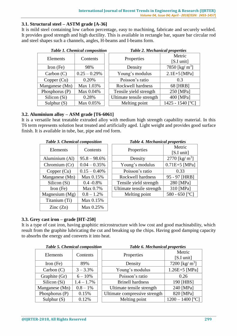
3.1. Structural steel – ASTM grade [A-36]
It is mild steel containing low carbon percentage, easy to machining, fabricate and securely welded.
It provides good strength and high ductility. This is available in rectangle bar, square bar circular rod
and steel shapes such a channels, angles, H-beams and I-beams form.
Table 1. Chemical composition Table 2. Mechanical properties
Elements Contents
Properties Metric
[S.I unit]
Iron (Fe) 98% Density 7850 [kg/ m3]
Carbon (C) 0.25 – 0.29% Young’s modulus 2.1E+5 [MPa]
Copper (Cu) 0.20% Poisson’s ratio 0.3
Manganese (Mn) Max 1.03% Rockwell hardness 68 [HRB]
Phosphorus (P) Max 0.04% Tensile yield strength 250 [MPa]
Silicon (Si) 0.28% Ultimate tensile strength 400 [MPa]
Sulphur (S) Max 0.05% Melting point 1425 - 1540 [oC]
3.2. Aluminium alloy – ASM grade [T6-6061] It is a versatile heat treatable extruded alloy with medium high strength capability material. In this
T6 term represents solution heat treated and artificially aged. Light weight and provides good surface
finish. It is available in tube, bar, pipe and rod form.
Table 3. Chemical composition Table 4. Mechanical properties
Elements Contents
Properties Metric
[S.I unit]
Aluminium (Al) 95.8 – 98.6% Density 2770 [kg/ m3]
Chromium (Cr) 0.04 – 0.35% Young’s modulus 0.71E+5 [MPa]
Copper (Cu) 0.15 – 0.40% Poisson’s ratio 0.33
Manganese (Mn) Max 0.15% Rockwell hardness 95 - 97 [HRB]
Silicon (Si) 0.4 -0.8% Tensile yield strength 280 [MPa]
Iron (Fe) Max 0.7% Ultimate tensile strength 310 [MPa]
Magnesium (Mg) 0.8 – 1.2% Melting point 580 - 650 [oC]
Titanium (Ti) Max 0.15%
Zinc (Zn) Max 0.25%
3.3. Grey cast iron – grade [HT-250]
It is a type of cast iron, having graphitic microstructure with low cost and good machinability, which
result from the graphite lubricating the cut and breaking up the chips. Having good damping capacity
to absorbs the energy and converts it into heat.
Table 5. Chemical composition Table 6. Mechanical properties
Elements Contents
Properties Metric
[S.I unit]
Iron (Fe) 89% Density 7200 [kg/ m3]
Carbon (C) 3 – 3.3% Young’s modulus 1.26E+5 [MPa]
Graphite (Gr) 6 – 10% Poisson’s ratio 0.26
Silicon (Si) 1.4 – 1.7% Brinell hardness 190 [HBS]
Manganese (Mn) 0.8 – 1% Ultimate tensile strength 240 [MPa]
Phosphorus (P) 0.15% Ultimate compressive strength 820 [MPa]
Sulphur (S) 0.12% Melting point 1200 – 1400 [oC]
International Journal of Recent Trends in Engineering & Research (IJRTER) Volume 04, Issue 04; April - 2018[ISSN: 2455-1457]
@IJRTER-2018, All Rights Reserved 300
IV. SPECIFICATION AND LOADING CONDITION OF CONNECTING ROD
4.1. Configuration of Suzuki gixxer SF model
Considering 155cc engine,
Engine type - Air cooled, 4-stroke, having
Bore, B or Piston diameter, D = 56 mm
Stroke, S = 62.9 mm
Number of Cylinders, n = 1
Displacement = 154.9 cm3 i.e. [π/4*B2*S*n]
Length of connecting rod, L = 2 * stroke of piston= 2 * 62.9 = 125.8mm
Maximum Power, P = 14.8 bhp at 8000 RPM
Maximum Torque, T = 14 N-m at 6000 RPM
4.2. Specification of Petrol
Compression Ratio of PETROL [C8H18] = 9.35:1
Density of petrol, ρ = 737.22E-9 kg / mm3
Molecular weight, M = 114.228 g / mole
Ideal gas constant, R = 8.314 J / mol-K
Temperature, T = 27oC+273 = 300 Kelvin (K) [ Ideal room temperature]
From perfect gas equation,
PV = mRspecific T
P = Pressure, V= Volume, m = Mass, T = Ideal room temperature and Rspecific = Specific gas constant
Mass, m = Density * Volume
= 737.22E-9 * 154.9E3
= 0.1142 kg * 9.81= 1.12 N.
Rspecific = R / M
= 8.314 / 0.11422 = 72.79 J / kg.K
Substitute all above values in perfect gas equation, we get
Pressure (P) = 16 MPa or 160 Bar.
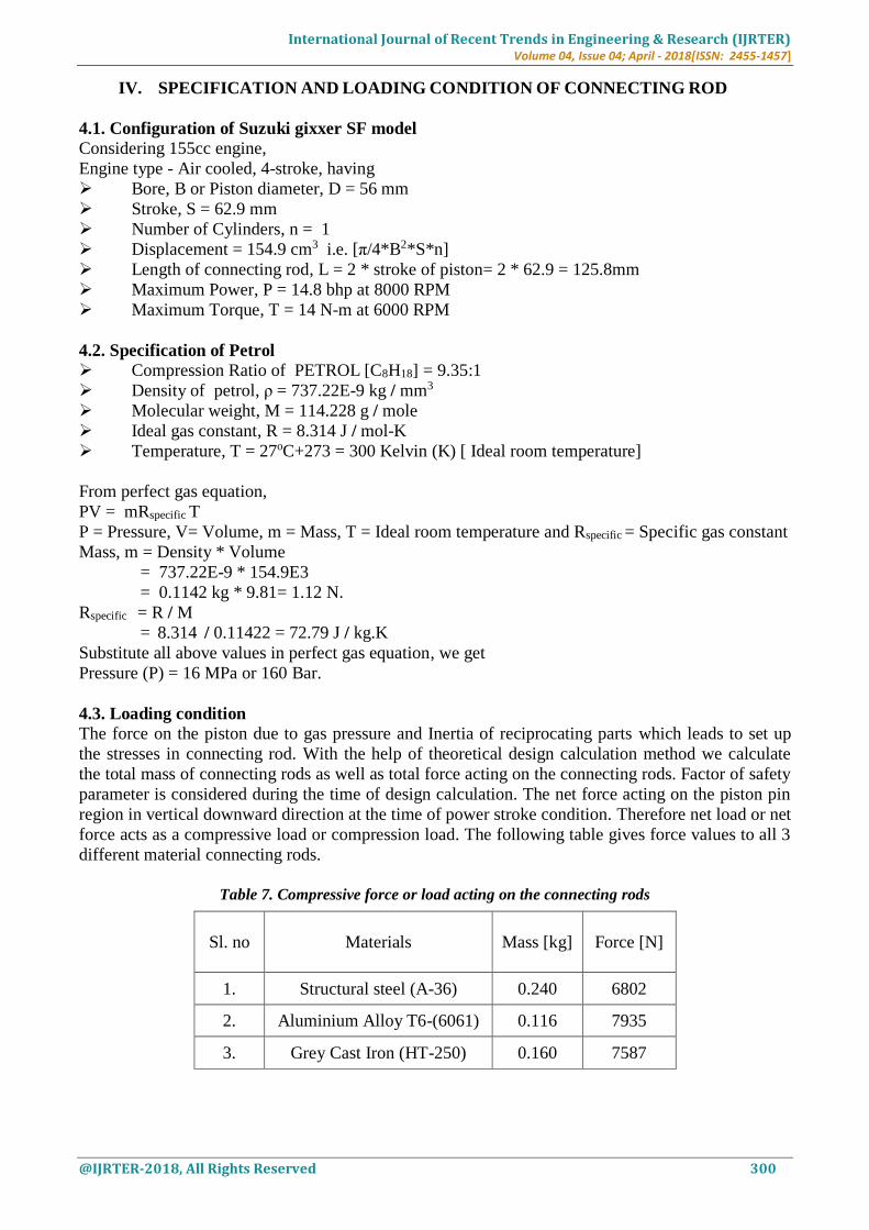
4.3. Loading condition
The force on the piston due to gas pressure and Inertia of reciprocating parts which leads to set up
the stresses in connecting rod. With the help of theoretical design calculation method we calculate
the total mass of connecting rods as well as total force acting on the connecting rods. Factor of safety
parameter is considered during the time of design calculation. The net force acting on the piston pin
region in vertical downward direction at the time of power stroke condition. Therefore net load or net
force acts as a compressive load or compression load. The following table gives force values to all 3
different material connecting rods.
Table 7. Compressive force or load acting on the connecting rods
Sl. no Materials
Mass [kg]
Force [N]
1. Structural steel (A-36) 0.240 6802
2. Aluminium Alloy T6-(6061) 0.116 7935
3. Grey Cast Iron (HT-250) 0.160 7587
International Journal of Recent Trends in Engineering & Research (IJRTER) Volume 04, Issue 04; April - 2018[ISSN: 2455-1457]
@IJRTER-2018, All Rights Reserved 301
The following parameters or specifications required to prepare a complete 3D model or geometry of
connecting rod. These values are estimated from design calculation method.
Table 8. Specification of connecting rod
Sl.no Parameters Aluminium
Alloy
Structural
Steel
Grey Cast
Iron
1. Thickness of flange and web of connecting rod [t] 5.5 4.7 4
2. Width of the section [B= 4t] 22 19 16
3. Height of the section [H=5t] 28 24 20
4. Height at the big end H1= [1.1H - 1.125H] 31 26 22
5. Height at the small end H2= [0.75H – 0.9H] 21 18 15
6. Inner diameter of small end 40 40 40
7. Outer diameter of small end 50 50 50
8. Length of small end 25 25 25
9. Inner diameter of big end 52 52 52
10. Outer diameter of big end 69 69 69
11. Length of big end 32 32 32
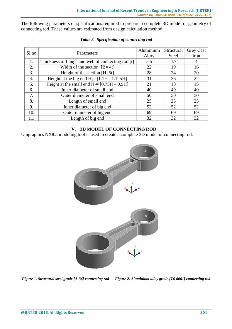
V. 3D MODEL OF CONNECTING ROD
Unigraphics NX8.5 modeling tool is used to create a complete 3D model of connecting rod.
Figure 1. Structural steel grade [A-36] connecting rod Figure 2. Aluminium alloy grade [T6-6061] connecting rod
International Journal of Recent Trends in Engineering & Research (IJRTER) Volume 04, Issue 04; April - 2018[ISSN: 2455-1457]
@IJRTER-2018, All Rights Reserved 302
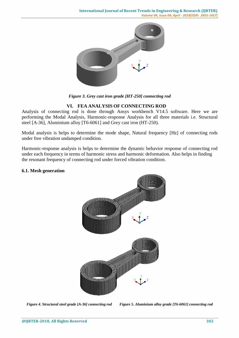
Figure 3. Grey cast iron grade [HT-250] connecting rod
VI. FEA ANALYSIS OF CONNECTING ROD
Analysis of connecting rod is done through Ansys workbench V14.5 software. Here we are
performing the Modal Analysis, Harmonic-response Analysis for all three materials i.e. Structural
steel [A-36], Aluminium alloy [T6-6061] and Grey cast iron (HT-250).
Modal analysis is helps to determine the mode shape, Natural frequency [Hz] of connecting rods
under free vibration undamped condition.
Harmonic-response analysis is helps to determine the dynamic behavior response of connecting rod
under each frequency in terms of harmonic stress and harmonic deformation. Also helps in finding
the resonant frequency of connecting rod under forced vibration condition.
6.1. Mesh generation
Figure 4. Structural steel grade [A-36] connecting rod Figure 5. Aluminium alloy grade [T6-6061] connecting rod
International Journal of Recent Trends in Engineering & Research (IJRTER) Volume 04, Issue 04; April - 2018[ISSN: 2455-1457]
@IJRTER-2018, All Rights Reserved 303
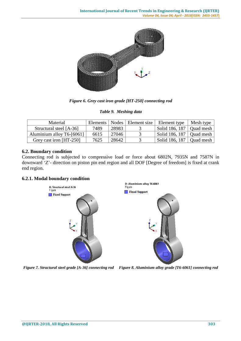
Figure 6. Grey cast iron grade [HT-250] connecting rod
Table 9. Meshing data
Material Elements Nodes Element size Element type Mesh type
Structural steel [A-36] 7489 28983 3 Solid 186, 187 Quad mesh
Aluminium alloy T6-[6061] 6615 27046 3 Solid 186, 187 Quad mesh
Grey cast iron [HT-250] 7625 28642 3 Solid 186, 187 Quad mesh
6.2. Boundary condition
Connecting rod is subjected to compressive load or force about 6802N, 7935N and 7587N in
downward ‘Z’- direction on piston pin end region and all DOF [Degree of freedom] is fixed at crank
end region.
6.2.1. Modal boundary condition
Figure 7. Structural steel grade [A-36] connecting rod Figure 8. Aluminium alloy grade [T6-6061] connecting rod
International Journal of Recent Trends in Engineering & Research (IJRTER) Volume 04, Issue 04; April - 2018[ISSN: 2455-1457]
@IJRTER-2018, All Rights Reserved 304
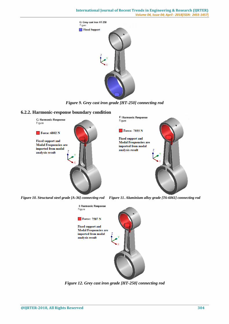
Figure 9. Grey cast iron grade [HT-250] connecting rod
6.2.2. Harmonic-response boundary condition
Figure 10. Structural steel grade [A-36] connecting rod Figure 11. Aluminium alloy grade [T6-6061] connecting rod
Figure 12. Grey cast iron grade [HT-250] connecting rod
International Journal of Recent Trends in Engineering & Research (IJRTER) Volume 04, Issue 04; April - 2018[ISSN: 2455-1457]
@IJRTER-2018, All Rights Reserved 305
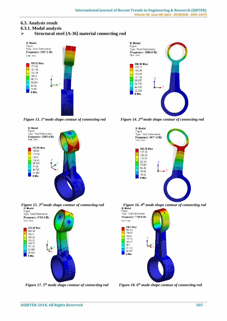
6.3. Analysis result
6.3.1. Modal analysis
Structural steel [A-36] material connecting rod
Figure 13. 1st mode shape contour of connecting rod Figure 14. 2nd mode shape contour of connecting rod
Figure 15. 3rd mode shape contour of connecting rod Figure 16. 4th mode shape contour of connecting rod
Figure 17. 5th mode shape contour of connecting rod Figure 18. 6th mode shape contour of connecting rod
International Journal of Recent Trends in Engineering & Research (IJRTER) Volume 04, Issue 04; April - 2018[ISSN: 2455-1457]
@IJRTER-2018, All Rights Reserved 306
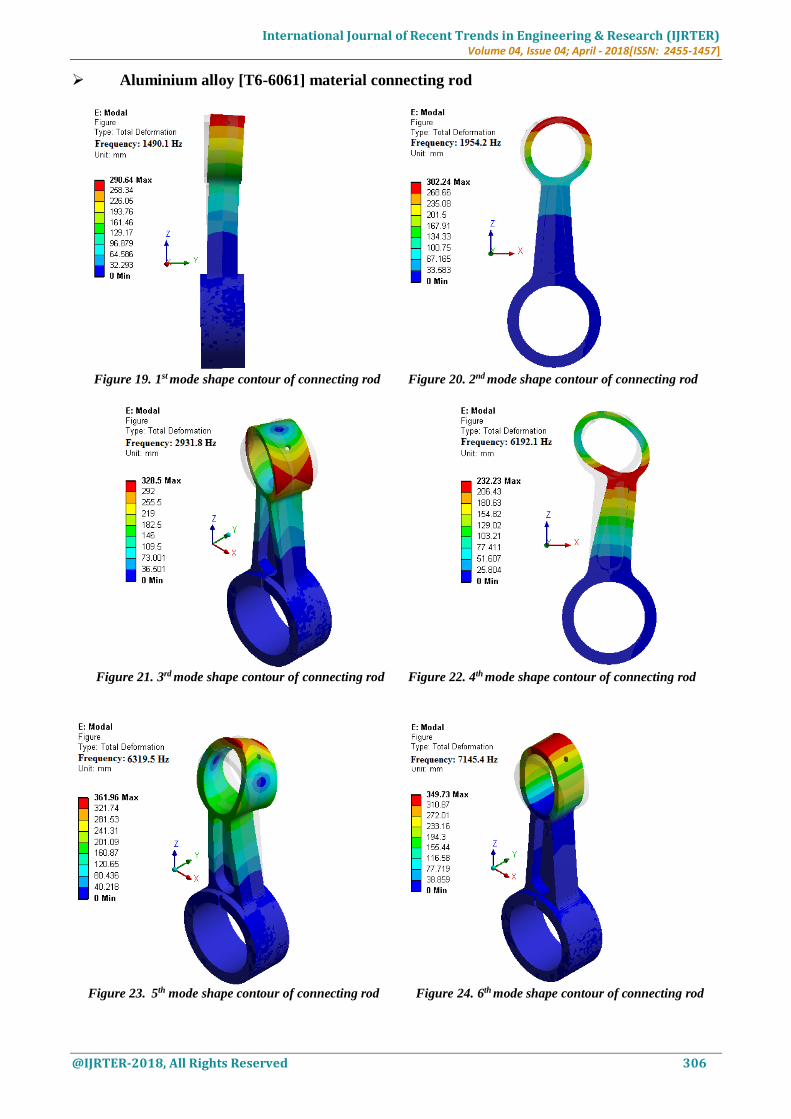
Aluminium alloy [T6-6061] material connecting rod
Figure 19. 1st mode shape contour of connecting rod Figure 20. 2nd mode shape contour of connecting rod
Figure 21. 3rd mode shape contour of connecting rod Figure 22. 4th mode shape contour of connecting rod
Figure 23. 5th mode shape contour of connecting rod Figure 24. 6th mode shape contour of connecting rod
International Journal of Recent Trends in Engineering & Research (IJRTER) Volume 04, Issue 04; April - 2018[ISSN: 2455-1457]
@IJRTER-2018, All Rights Reserved 307
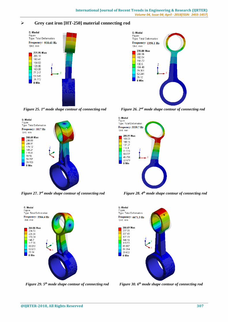
Grey cast iron [HT-250] material connecting rod
Figure 25. 1st mode shape contour of connecting rod Figure 26. 2nd mode shape contour of connecting rod
Figure 27. 3rd mode shape contour of connecting rod Figure 28. 4th mode shape contour of connecting rod
Figure 29. 5th mode shape contour of connecting rod Figure 30. 6th mode shape contour of connecting rod
International Journal of Recent Trends in Engineering & Research (IJRTER) Volume 04, Issue 04; April - 2018[ISSN: 2455-1457]
@IJRTER-2018, All Rights Reserved 308
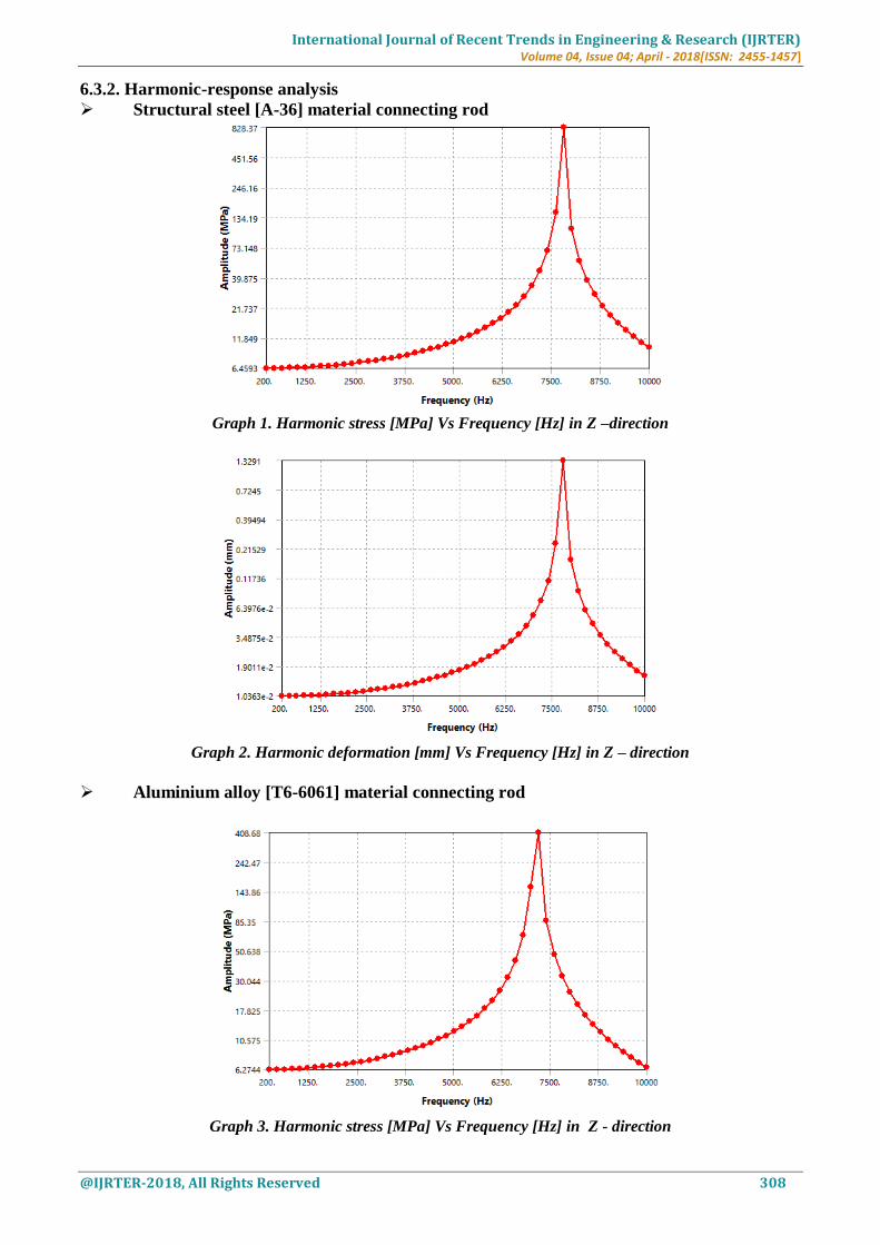
6.3.2. Harmonic-response analysis
Structural steel [A-36] material connecting rod
Graph 1. Harmonic stress [MPa] Vs Frequency [Hz] in Z –direction
Graph 2. Harmonic deformation [mm] Vs Frequency [Hz] in Z – direction
Aluminium alloy [T6-6061] material connecting rod
Graph 3. Harmonic stress [MPa] Vs Frequency [Hz] in Z - direction
International Journal of Recent Trends in Engineering & Research (IJRTER) Volume 04, Issue 04; April - 2018[ISSN: 2455-1457]
@IJRTER-2018, All Rights Reserved 309
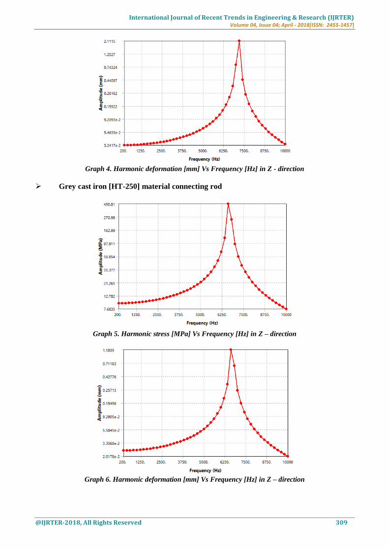
Graph 4. Harmonic deformation [mm] Vs Frequency [Hz] in Z - direction
Grey cast iron [HT-250] material connecting rod
Graph 5. Harmonic stress [MPa] Vs Frequency [Hz] in Z – direction
Graph 6. Harmonic deformation [mm] Vs Frequency [Hz] in Z – direction
International Journal of Recent Trends in Engineering & Research (IJRTER) Volume 04, Issue 04; April - 2018[ISSN: 2455-1457]
@IJRTER-2018, All Rights Reserved 310
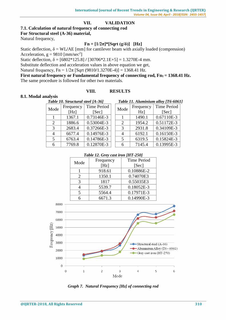
VII. VALIDATION
7.1. Calculation of natural frequency of connecting rod
For Structural steel (A-36) material,
Natural frequency,
Fn = [1/2π]*[Sqrt (g/δ)] [Hz]
Static deflection, δ = WL/AE [mm] for cantilever beam with axially loaded (compression)
Acceleration, g = 9810 [mm/sec2]
Static deflection, δ = [6802*125.8] / [30706*2.1E+5] = 1.3270E-4 mm.
Substitute deflection and acceleration values in above equation we get,
Natural frequency, Fn = 1/2π [Sqrt (9810/1.3270E-4)] = 1368.41 Hz.
First natural frequency or Fundamental frequency of connecting rod, Fn1 = 1368.41 Hz.
The same procedure is followed for other two materials.
VIII. RESULTS
8.1. Modal analysis Table 10. Structural steel [A-36] Table 11. Aluminium alloy [T6-6061]
Mode Frequency
[Hz]
Time Period
[Sec]
Mode Frequency
Hz]
Time Period
[Sec]
1 1367.1 0.73146E-3 1 1490.1 0.67110E-3
2 1886.6 0.53004E-3 2 1954.2 0.51172E-3
3 2683.4 0.37266E-3 3 2931.8 0.34109E-3
4 6677.4 0.14976E-3 4 6192.1 0.16150E-3
5 6763.4 0.14786E-3 5 6319.5 0.15824E-3
6 7769.8 0.12870E-3 6 7145.4 0.13995E-3
Table 12. Grey cast iron [HT-250]
Mode Frequency
[Hz]
Time Period
[Sec]
1 918.61 0.10886E-2
2 1350.1 0.74070E3
3 1817 0.55035E3
4 5539.7 0.18052E-3
5 5564.4 0.17971E-3
6 6671.3 0.14990E-3
Graph 7. Natural Frequency [Hz] of connecting rod
International Journal of Recent Trends in Engineering & Research (IJRTER) Volume 04, Issue 04; April - 2018[ISSN: 2455-1457]
@IJRTER-2018, All Rights Reserved 311
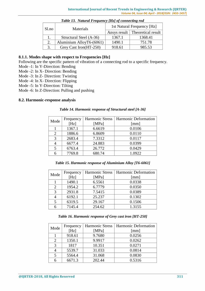
Table 13. Natural Frequency [Hz] of connecting rod
Sl.no Materials 1st Natural Frequency [Hz]
Ansys result Theoretical result
1. Structural Steel (A-36) 1367.1 1368.41
2. Aluminium AlloyT6-(6061) 1490.1 751.78
3. Grey Cast Iron(HT-250) 918.61 985.53
8.1.1. Modes shape with respect to Frequencies [Hz]
Following are the specific pattern of vibration of a connecting rod to a specific frequency.
Mode -1: In Y-Direction: Bending
Mode -2: In X- Direction: Bending
Mode -3: In Z- Direction: Twisting
Mode -4: In X- Direction: Flipping
Mode -5: In Y-Direction: Tilting
Mode -6: In Z-Direction: Pulling and pushing
8.2. Harmonic-response analysis
Table 14. Harmonic response of Structural steel [A-36]
Mode Frequency
[Hz]
Harmonic Stress
[MPa]
Harmonic Deformation
[mm]
1 1367.1 6.6619 0.0106
2 1886.6 6.8609 0.0110
3 2683.4 7.3312 0.0117
4 6677.4 24.883 0.0399
5 6763.4 26.772 0.0429
6 7769.8 680.74 1.0922
Table 15. Harmonic response of Aluminium Alloy [T6-6061]
Mode Frequency
[Hz]
Harmonic Stress
[MPa]
Harmonic Deformation
[mm]
1 1490.1 6.5561 0.0338
2 1954.2 6.7779 0.0350
3 2931.8 7.5415 0.0389
4 6192.1 25.237 0.1302
5 6319.5 29.167 0.1506
6 7145.4 254.62 1.3155
Table 16. Harmonic response of Grey cast iron [HT-250]
Mode Frequency
[Hz]
Harmonic Stress
[MPa]
Harmonic Deformation
[mm]
1 918.61 9.7680 0.0256
2 1350.1 9.9917 0.0262
3 1817 10.351 0.0271
4 5539.7 31.033 0.0814
5 5564.4 31.068 0.0830
6 6671.3 202.44 0.5316
International Journal of Recent Trends in Engineering & Research (IJRTER) Volume 04, Issue 04; April - 2018[ISSN: 2455-1457]
@IJRTER-2018, All Rights Reserved 312
From harmonic–response result table, we observed that connecting rod is undergoes peak vibration at
mode number 6 for all three materials. Mode number 6 is the most worst or critical frequency of the
connecting rod because which produce undesirable noise, excessive stresses and also partial or
complete failure of part. But harmonic stress for aluminium alloy and grey cast iron material at mode
number 6 is well below the yield strength. Thus both materials are safe. Maximum damage occurs on
structural steel connecting rod. Hence design of structural steel connecting rod should be carried out
for first five modes only.
IX. CONCLUSION
Harmonic stress at mode number 6 is peak for structural steel connecting rod. Thus maximum
damage or complete failure occurs in structural steel connecting rod.
Design of structural steel connecting rod should be carried out for first five modes only.
Harmonic stress for aluminium alloy and grey cast iron connecting rod is well below the yield
strength for all modes. Hence both materials are safe.
Grey cast iron material connecting rod is selected for its dynamic behavior response i.e. it is
very safe in harmonic stress region.
REFERENCES I. K. Sudershan Kumar, Dr. K. Tirupathi Reddy, Syed Altaf Hussan, “Modeling and Analysis of Two Wheeler
Connecting Rod”, International Journal of Modern Engineering Research, vol-2, Issue-5, Pp-3367-3371, Sep-
Oct-2012.
II. Kuldeep B, Arun L.R, Mohammed Faheem, “Analysis and Optimization of Connecting Rod using Alfasic
Composites”, ISSN: 2319-8753 International Journal of Innovative Research in Science, Engineering and
Technology, vol. 2, Issue 6, June 2013.
III. Santhosh Reddy, “Load Analysis and Multi Body Dynamics Analysis of Connecting Rod in Single Cylinder 4
Stroke Engine”, International Journal for Scientific Research & Development, vol.-3, Issue 08, 2015 | ISSN
(online): 2321-0613.
IV. R.Ravi, B.V Subhramanyam, “Dynamic Load Analysis and Optimization of a Connecting Rod”, IJRMET vol.-
4, April 2014 ISSN: 2249-5762 (Online) | ISSN : 2249-5770 (Print)