mobile cars instrument for combustion and plasma diagnostics
TRANSCRIPT
Mobile CARS instrument for combustion andplasma diagnostics
Torger J. Anderson, Gregory M. Dobbs, and Alan C. Eckbreth
A compact and easily transportable coherent anti-Stokes Raman spectroscopy system for combustion andplasma diagnostics is described. The instrument is readily adaptable to a wide variety of test environmentsand experiments. The system is capable of withstanding high noise and vibration levels and is remotelyoperable to protect the operator and delicate components from high noise levels or hazardous environments.It is intended for single-pulse temperature and concentration measurements in practical combustion systems,such as gas turbines, diesel engines, and plasma process applications. The system is operational, and initialmeasurement demonstrations in a supersonic combusting flow are described.
1. Introduction
Coherent anti-Stokes Raman spectroscopy (CARS)is a nonlinear optical technique for gas temperatureand species concentration measurements which hasconsiderable demonstrated potential for analysis ofpractical combustion and plasma systems.lA Requir-ing no physical probe, it is nonintrusive and capable ofhigh spatial resolution and accurate measurements formost common combustion species. The use of short-pulse lasers makes the measurements virtually instan-taneous with respect to the process being observed.
Due to the complexity of the optical system, mostCARS systems to date have been laboratory systemsset up on large optical tables analyzing combustionsystems integrated in the CARS experiment. A fewinstruments have been tailored to test facilities formeasurements in practical combustion devices,4 5 but,because of their bulk and lack of flexibility, their usehas been mostly restricted to the facilities in whichthey were first installed. In contrast, plumbed sys-tems have been constructed in which a laser or CARSsystem has been centrally located with tubes to directthe laser beams to the test site.6 7 With such systems,the addition of new facilities is complex, and CARScapability is not provided at sites remote from thecentrally located laser.
To overcome these limitations, we developed a mo-bile CARS instrument which is compact and flexibleenough to be accommodated by most test facilities andcombustion experiments. The system offers a remoteoperation capability for installations in hazardous orhigh noise environments. Although compact, it has
The authors are with United Technologies Research Center, EastHartford, Connecticut 06108.
Received 7 June 1986.0003-6935/86/224076-10$02.00/0.© 1986 Optical Society of America.
configurational flexibility to meet future needs anddevelopments. In its first field application, the mobileCARS system demonstrated measurements in a super-sonic combusting flow. Some results of this demon-stration are included. Future developments, includ-ing a near-real-time presentation of temperature andspecies concentration measurements, will also be de-scribed.
II. CARS Overview
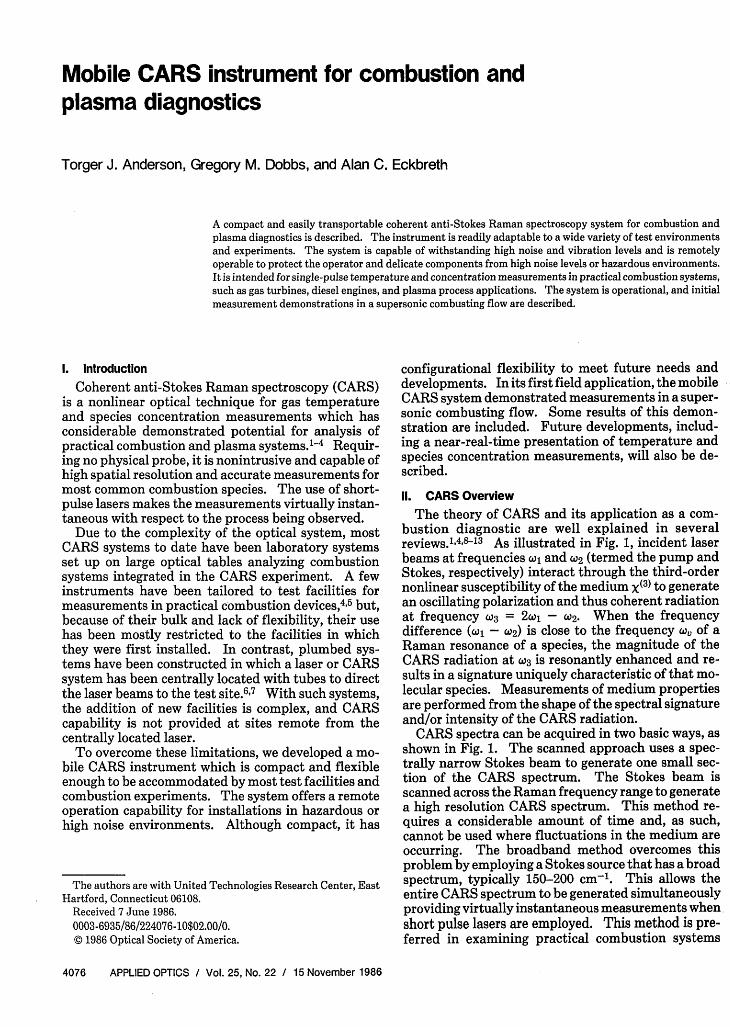
The theory of CARS and its application as a com-bustion diagnostic are well explained in severalreviews.1"4 '8 3 As illustrated in Fig. 1, incident laserbeams at frequencies o and (2 (termed the pump andStokes, respectively) interact through the third-ordernonlinear susceptibility of the medium X(3) to generatean oscillating polarization and thus coherent radiationat frequency Wo3 = 2 - W2. When the frequencydifference (l - WO2) is close to the frequency x, of aRaman resonance of a species, the magnitude of theCARS radiation at (3 is resonantly enhanced and re-sults in a signature uniquely characteristic of that mo-lecular species. Measurements of medium propertiesare performed from the shape of the spectral signatureand/or intensity of the CARS radiation.
CARS spectra can be acquired in two basic ways, asshown in Fig. 1. The scanned approach uses a spec-trally narrow Stokes beam to generate one small sec-tion of the CARS spectrum. The Stokes beam isscanned across the Raman frequency range to generatea high resolution CARS spectrum. This method re-quires a considerable amount of time and, as such,cannot be used where fluctuations in the medium areoccurring. The broadband method overcomes thisproblem by employing a Stokes source that has a broadspectrum, typically 150-200 cm-'. This allows theentire CARS spectrum to be generated simultaneouslyproviding virtually instantaneous measurements whenshort pulse lasers are employed. This method is pre-ferred in examining practical combustion systems
4076 APPLIED OPTICS / Vol. 25, No. 22 / 15 November 1986
* Phase matching
-I kk 2- k3
Ikil = niwi /c
I -ABroadband
A\ I -AW2 WI 'J3
Fig. 1. Coherent anti-Stokes Raman spectroscopy.
where turbulence and temperature fluctuations arealmost always present.
For efficient signal generation, the incident laserbeams must be so aligned that the three-wave mixingprocess is properly phased. Phase matching ensuresthat the CARS signal generated at one spatial locationwill be in phase with the signals generated elsewhereand that constructive interference occurs. If phasematching is not satisfied, the CARS signals generatedat various spatial locations will destructively interfere,and no net signal will be produced. In gases, phasematching is easily satisfied by a collinear arrangementof the laser beams. In many diagnostic circumstances,however, collinear phase matching leads to poor spa-tial resolution because the CARS radiation undergoesan integrative growth process. As a result, a phasematching geometry must be selected based on trade-offs between signal strength, spatial resolution, andthe ability to filter the CARS signal from the laserbeams. A CARS system to be used in a variety ofexperiments must be capable of easily employing anumber of varied phase matching geometries.13-15
A high power laser is required to provide the sourceof optical energy for a system which generates CARSfor diagnostic use. A Nd:YAG laser is generally usedbecause of its ability to generate a very high peakpower with Q-switching. Frequency doubling pro-duces a beam in the visible region near the CARSspectral range to provide the CARS pump beam. Adye laser generates the Stokes beam which can betuned to the appropriate wavelength for CARS to beobserved from the species of interest. This laser ispumped by a portion of the frequency-doubledNd:YAG beam. An optical system combines thepump and Stokes beams in the desired phase matchinggeometry, focuses them at the measurement point, andrecollimates them along with the CARS beam. It alsoseparates the relatively weak CARS signal from thehigh power laser beams and directs the signal to aspectrograph for analysis. Measurements are oftenrequired in experiments conducted in hazardous ornoisy environments, and, as such, the system must becapable of being operated remotely. Because a largeamount of data is acquired at a high rate, a computer
system is required to store it for future analysis.These basic considerations provide the perspectivearound which our mobile CARS system was designed.
Ill. General Design
The mobile CARS instrument consists of three basicsubsystems which were derived from an earlier instru-ment. 4 A cart-mounted transmitter contains aNd:YAG laser and the associated optics necessary toalign the system and generate the laser beams. Thelaser power supply, because of its bulk, remains in aseparate frame and links the transmitter to its controlsthrough a single umbilical. A receiver separates theCARS signal from unwanted light, utilizes the residuallaser beams to generate a reference CARS signal forconcentration measurements, and focuses the CARSsignal into an optical fiber for transmission to the thirdsubsystem, the data acquisition and control rack. Thelatter contains a spectrograph to analyze the CARSsignal and a data acquisition computer to store CARSspectra on magnetic tape. It also contains remotecontrols for the laser and actuators in the transmitterand receiver which are adjusted to maximize the CARSsignal. A separate and larger computer is currentlyused to analyze the CARS spectral information tomake temperature and species concentration measure-ments.
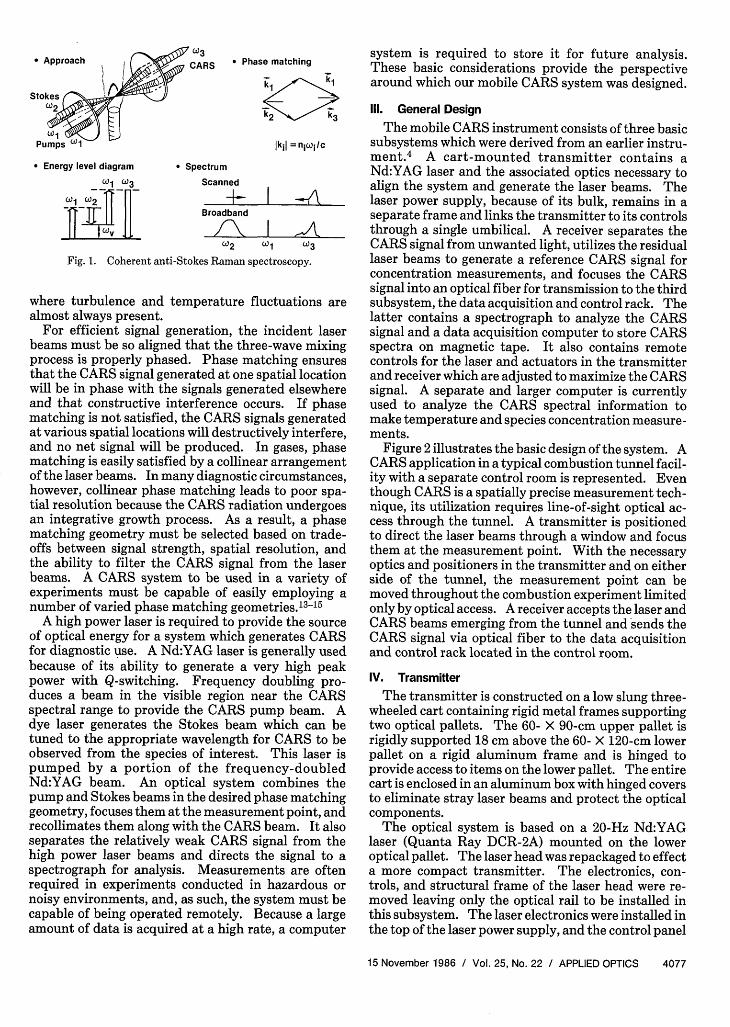
Figure 2 illustrates the basic design of the system. ACARS application in a typical combustion tunnel facil-ity with a separate control room is represented. Eventhough CARS is a spatially precise measurement tech-nique, its utilization requires line-of-sight optical ac-cess through the tunnel. A transmitter is positionedto direct the laser beams through a window and focusthem at the measurement point. With the necessaryoptics and positioners in the transmitter and on eitherside of the tunnel, the measurement point can bemoved throughout the combustion experiment limitedonly by optical access. A receiver accepts the laser andCARS beams emerging from the tunnel and sends theCARS signal via optical fiber to the data acquisitionand control rack located in the control room.
IV. Transmitter
The transmitter is constructed on a low slung three-wheeled cart containing rigid metal frames supportingtwo optical pallets. The 60- X 90-cm upper pallet isrigidly supported 18 cm above the 60- X 120-cm lowerpallet on a rigid aluminum frame and is hinged toprovide access to items on the lower pallet. The entirecart is enclosed in an aluminum box with hinged coversto eliminate stray laser beams and protect the opticalcomponents.
The optical system is based on a 20-Hz Nd:YAGlaser (Quanta Ray DCR-2A) mounted on the loweroptical pallet. The laser head was repackaged to effecta more compact transmitter. The electronics, con-trols, and structural frame of the laser head were re-moved leaving only the optical rail to be installed inthis subsystem. The laser electronics were installed inthe top of the laser power supply, and the control panel
15 November 1986 / Vol. 25, No. 22 / APPLIED OPTICS 4077
Approach - W3 AR
Stokes
PumPs 1i
* Energy level diagram
Wi (03
WI ii
* SpectrumScanned
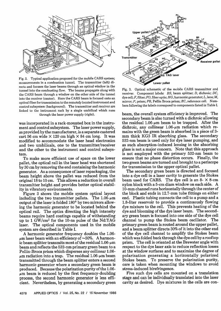
Fig. 2. Typical application proposed for the mobile CARS system;measurements in a combustion tunnel. The transmitter (left) di-rects and focuses the laser beams through an optical window in thetunnel into the combusting flow. The beams propagate along withthe CARS beam through a window on the other side of the tunnelinto the receiver (center). Here the CARS beam is focused onto anoptical fiber for transmission to the remotely located instrument andcontrol subsystem (background). The transmitter and receiver arelinked to the instrument rack by a single umbilical which runs
through the laser power supply (right).
was incorporated in a rack-mounted box in the instru-ment and control subsystem. The laser power supply,as provided by the manufacturer, is a separate casteredcart 56 cm wide X 120 cm high X 84 cm long. It wasmodified to accommodate the laser head electronicsand two umbilicals, one to the transmitter/receiverand the other to the instrument and control subsys-tem.
To make more efficient use of space on the lowerpallet, the optical rail in the laser head was shortenedby 30 cm by removing the end containing the harmonicgenerator. As a consequence of laser repackaging, thebeam height above the pallet was reduced from theoriginal 18 to 10 cm. This allows a reduction in overalltransmitter height and provides better optical stabil-ity in vibratory environments.
Figure 3 shows the mobile system optical layoutincluding the two transmitter pallets. The 1.06-,gmoutput of the laser is folded 1800 by two mirrors allow-ing the harmonic generator to be located behind theoptical rail. The optics directing the high intensitybeams require hard coatings capable of withstandingup to 1 GW/cm 2 for the 10-ns pulse of the Nd:YAGlaser. The optical components used in the mobilesystem are described in Table I.
A harmonic generator frequency doubles the 1.06-,um laser beam with an efficiency of -30%. A harmon-ic beam splitter transmits most of the residual 1.06-,Mmbeam and reflects the 532-nm primary green beam to aPellin-Broca prism which disperses any collinear 1.06-,um radiation into a trap. The residual 1.06-Am beamtransmitted through the beam splitter enters a secondharmonic generator where a secondary green beam isproduced. Because the polarization purity of the 1.06-,um beam is reduced by the first frequency-doublingprocess, the second harmonic generator is less effi-cient. Nevertheless, by generating a secondary green
Fig. 3. Optical schematic of the mobile CARS transmitter andreceiver. Component labels: BS, beam splitter; D, dichroic; DC,dye cell; F, filter; FO, fiber optic; HG, harmonic generator; L, lens; M,mirror; P, prism; PB, Pellin Broca prism; RC, reference cell. Num-bers following the labels correspond to components listed in Table I.
beam, the overall system efficiency is improved. Thesecondary beam is also turned with a dichroic allowingthe residual 1.06-Mm beam to be trapped. After thedichroic, any collinear 1.06-,um radiation which re-mains with the green beam is absorbed in a piece of 3-mm thick KG3 IR absorbing glass. The secondary532-nm beam is used only for dye laser pumping, andas such absorption-induced lensing in the absorbingglass is not a major concern. Note that this approachis not employed with the primary 532-nm beam toensure that no phase distortion occurs. Finally, thetwo green beams are turned and brought to a periscopefor transmission to the upper optical pallet.
The secondary green beam is directed and focusedinto a dye cell in a laser cavity to generate the Stokesbeam used for CARS. The dye cell is an 8- X 8-cmnylon block with a 5-cm diam window on each side. A10-mm channel runs horizontally through the center ofthe block and ends in 12.7-mm tube fittings on eitherend. Plastic tubing connects the cell to a pump and a1.8-liter reservoir to provide a continuously flowingdye mixture to the cell. This prevents heating of thedye and blooming of the dye laser beam. The second-ary green beam is focused into one side of the dye cellchannel to pump the Stokes beam oscillator. Theprimary green beam is routed around the upper pallet,and a beam splitter directs 30% of it into the other endof the dye cell channel to amplify the Stokes beamwhich was folded back through the dye cell by a rooftopprism. The cell is oriented at the Brewster angle withrespect to the dye laser axis to reduce reflection lossesat the window surfaces and to maximize the degree ofpolarization generating a horizontally polarizedStokes beam. To preserve the polarization purity,care is taken when mounting the windows to avoidstress-induced birefringence.
Five such dye cells are mounted on a translationstage and can be individually translated into the lasercavity as desired. Dye mixtures in the cells are con-
4078 APPLIED OPTICS / Vol. 25, No. 22 / 15 November 1986
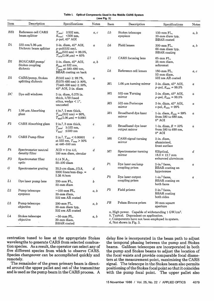
Table 1. Optical Components Used in the Mobile CARS System(see Fig. 3)
Item Description Specifications Notes Item Description Specifications Notes
BS3 Reference cell CARSbeam splitter
D1 532 -nm/1.06-,amDichroic beam splitter
D2 BOXCARS pump/Stokes couplingdichroic
D3 CARS/pump, Stokessplitting dichroic
DC Dye cell windows
F1 1.06 -,m Absorbingglass
F2 CARS Absorbing glass
F3 CARS Pump filter
F4 Spectrometer neutraldensity filter
FO Spectrometer fiberoptic
G Spectrometer grating
LI Dye laser pump lens
L2 Pump telescopeeyepiece
L3 Pump telescopeobjective
L4 Stokes telescopeobjective
Tmax: >532 nm,Rmax: <500 nm,p-pol, 450 AOI
2-in. diam, 450 AOI,p-pol(532 nm),Rmin(532 nm) = 99.5%,Tmin(1.06 Mm) = 85%
2-in. diam, 450 AOI,Rmax at 532 nm,Tmax at 580-680 nm,BBAR coating on back
R(532 nm) > 99.7%,R(570-680 nm) 2 80%,T(440-500 nm) > 50%,450 AOI, 2-in. diam
2-in. diam, 0.375 in.thick, /20 fusedsilica, wedge < 1",uncoated
4 in.2 , 2 mm thick,Tma(532 nm) = 90%,Tmin(.06,um) = 0.0001
2 in.2, 3 mm thick,Tmax: 532 nm,Tmin: 500 nm
2 in.2 , Tmin < 000001at 532 nm, Tmax > 50%at 440-550 nm
N/D = 0 to 4.0,100 mm diam, circular
0.14 N.A.,50-100 diam
20.3-cm diam, f/3.8,2000 lines/mm disp. =5.26 A/mm
200-mm FL,50-mm diam
-100-mm FL,30-mm diam,532 nm AR coated
200-mm FL,30-mm diam typ,532 nm AR coated
-50-mm FL,30-mm diam,BBAR coated
a, c L5 Stokes telescopeeyepiece
a L6 Field lenses
L7 CARS focusing lensa, b
L8 Reference cell lenses
a
M1 1.06-jum turning mirror
M2 532-nm Turningmirror
M3 532-nm Periscopemirror
M4 Broadband dye lasermirror
c M5 Broadband dye laseroutput mirror
c M6 CARS signal turningmirror
d M7 Spectrometer turningmirror
P1 Dye laser osc/amp
d coupling prism
P2 Dye laser outputcoupling prismb
a, b
a, b
P3 Field prisms
PB Pelam-Brocca prism
150-mm FL,30-mm diam typ,BBAR coated
300-mm FL,66-mm diam typ,BBAR coating
65-mm FL,25-mm diam,achromat
150-mm FL,52-mm diam,532 nm AR coated
2-in. diam, 450 AOI,p-pol, Rmin = 99.5%
2-in. diam, 450 AOI,p-pol, Rmin = 99.5%
2-in. diam, 450 AOI,s-pol, Rmin = 99%
1-in. diam, Rmin = 99%from 580 to 680 nm,00 AOI
1-in. diam, R = 50%from 580 to 680 nm,00 AOI
2-in. diam,aluminized,front surface
Elliptical,18.0 X 12.7 mmenhanced aluminum
2-in. 2 faces,BBAR coating onhypotenuse
1-in. 2 faces,BBAR coating onboth faces
2-in. 2 faces,BBAR coatingboth sides
20-mm squareaperture
a, High power. Capable of withstanding 1 GW/cm 2 .a, b b, Typical. Dependent on application.
c, Components have not been employed in system.d, Not shown in Fig. 3.
centration tuned to lase at the appropriate Stokeswavelengths to generate CARS from selected combus-tion species. As a result, the operator can select any offive different species from which to observe CARS.Species changeover can be accomplished quickly andremotely.
The remainder of the green primary beam is direct-ed around the upper pallet and out of the transmitterand is used as the pump beam in the CARS process. A
delay line is incorporated in the beam path to adjustthe temporal phasing between the pump and Stokesbeams. Galilean telescopes are incorporated in boththe pump and Stokes beams to adjust the location ofthe focal waists and provide comparable focal diame-ters at the measurement point, maximizing the CARSsignal. The telescope in the Stokes beam also permitspositioning of the Stokes focal point so that it coincideswith the pump focal point. The upper pallet also
15 November 1986 / Vol. 25, No. 22 / APPLIED OPTICS 4079
a, b
a, b
a, c
a
a
a
a
a
d
a
a
contains the optics required to modify the beams forthe specific application. For example, when a BOX-CARS phase matching scheme 314 is used, a beamsplitter is incorporated in one of the pump beam turn-ing mirrors to produce the two pump beams required.The choice of breadboard optical pallets in the trans-mitter and receiver was purposely made to allow modi-fications such as this to be made quickly and easily.
A dichroic beam splitter is used to combine thepump and Stokes beams in the proper phase-matchingorientation. The beams are then directed through aseries of right-angle turning prisms out of the trans-mitter toward the measurement point. Due to thewide variety of applications anticipated for the mobileCARS system, a generic system for directing the beamsto the measurement point could not be easily designed.As a result, the transmitter was designed with a rigidtower through which the pump and Stokes beams aredirected vertically. A lightweight detachable systemis constructed for each application and contains theturning prisms and field lenses necessary to direct thelaser beams to the measurement point and then torecollimate them.
The system also contains actuators to translate theoptics allowing measurements to be made at differentlocations in the experiment. Translation of the mea-surement point perpendicular to the laser beam axisrequires the use of stepping motors and translationstages to move turning prisms and a portion of thesystem structure. Translation along the beam axis isaccomplished simply by using a stepping motor tomove the two field lenses on a translation stage. Analternative method for axial translation is the installa-tion of Galilean telescopes in the phase-matched beampath in the transmitter and receiver.16 The measure-ment point can be moved over large distances along thebeam axis by making small changes in the telescopefocal lengths. This method provides a constant f/No.and allows all the moving optical components to beinstalled in the transmitter and receiver.
To provide a simple method for aligning the mobileCARS system, two small He-Ne lasers are incorporat-ed in the transmitter. The first, on the lower pallet,directs its beam through the back mirror of theNd:YAG laser allowing alignment of the laser itselfand of the frequency-doubling and beam-splittingcomponents to the beam axis on the lower pallet. Thesecond is on the upper pallet and is directed counter tothe Stokes beam path by inserting a pellicle in thatpath between the Stokes Galilean and the pump/Stokes beams combining optic. It is used to align theStokes oscillator/amplifier system. The retroreflec-tion from the Stokes cavity provides a reference beamout of the transmitter to align the pump beams to theStokes beam and to the combustion experiment.
In addition to the optical system, the transmittercontains an electrical terminal box for connections forthe laser and remote control actuators. The spacewithin the structure below the lower optical palletcontains a hydraulic jacking system for positioningand leveling the transmitter, a nitrogen purge system
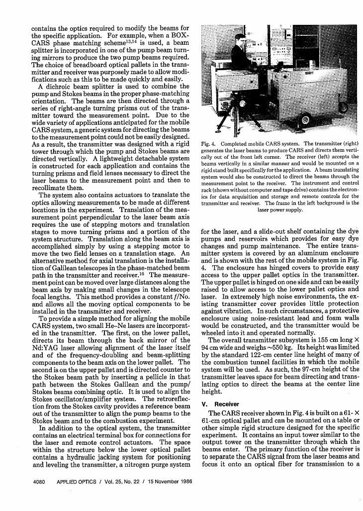
Fig. 4. Completed mobile CARS system. The transmitter (right)generates the laser beams to produce CARS and directs them verti-cally out of the front left corner. The receiver (left) accepts thebeams vertically in a similar manner and would be mounted on arigid stand built specifically for the application. A beam translatingsystem would also be constructed to direct the beams through themeasurement point to the receiver. The instrument and controlrack (shown without computer and tape drive) contains the electron-ics for data acquisition and storage and remote controls for thetransmitter and receiver. The frame in the left background is the
laser power supply.
for the laser, and a slide-out shelf containing the dyepumps and reservoirs which provides for easy dyechanges and pump maintenance. The entire trans-mitter system is covered by an aluminum enclosureand is shown with the rest of the mobile system in Fig.4. The enclosure has hinged covers to provide easyaccess to the upper pallet optics in the transmitter.The upper pallet is hinged on one side and can be easilyraised to allow access to the lower pallet optics andlaser. In extremely high noise environments, the ex-isting transmitter cover provides little protectionagainst vibration. In such circumstances, a protectiveenclosure using noise-resistant lead and foam wallswould be constructed, and the transmitter would bewheeled into it and operated normally.
The overall transmitter subsystem is 155 cm long X94 cm wide and weighs -550 kg. Its height was limitedby the standard 122-cm center line height of many ofthe combustion tunnel facilities in which the mobilesystem will be used. As such, the 97-cm height of thetransmitter leaves space for beam directing and trans-lating optics to direct the beams at the center lineheight.
V. Receiver
The CARS receiver shown in Fig. 4 is built on a 61- X61-cm optical pallet and can be mounted on a table orother simple rigid structure designed for the specificexperiment. It contains an input tower similar to theoutput tower on the transmitter through which thebeams enter. The primary function of the receiver isto separate the CARS signal from the laser beams andfocus it onto an optical fiber for transmission to a
4080 APPLIED OPTICS / Vol. 25, No. 22 / 15 November 1986
spectrograph. It also contains the equipment neces-sary to generate a reference CARS signal for makingconcentration measurements from CARS signal inten-sity.
The receiver optical system can be understood byreferring to Fig. 3. A field lens recollimates the beamsafter they exit the measurement point, and prismsdirect the beams into the receiver. A standard 532-nmturning mirror in the receiver is used as a dichroicseparating the CARS signal from much of the pumpand Stokes beams. A second 532-nm mirror reducesthe residual laser intensity further. These mirrors usehard coatings and are able to withstand the high inten-sities of the incident laser beams. After the beams aretransmitted through the two mirrors, the pump andStokes intensities are low enough that soft coated in-terference filters are used. A narrowband notch filterremoves the residual 532-nm pump beams, and a 3-mmpiece of BG-13 filter glass eliminates the residualStokes. In addition, an aperture spatially filters theCARS beam from other unwanted light including anycollinear CARS generated outside the measurementvolume.
An uncoated flat is installed at a 450 angle in theCARS beam path to split off a small portion to aphotomultiplier tube (PMT). A second narrowbandnotch filter installed in front of the PMT eliminatesany remaining 532-nm light. The PMT's large aper-ture (5 cm) makes it insensitive to any changes inCARS signal alignment resulting from adjustments inthe Stokes beam position. As a result, the operatorcan monitor the PMT signal strength while aligningthe Stokes beam focal point with that of the pumpbeams to maximize the CARS intensity. Although notshown in Fig. 3, baffling throughout the receiver mini-mizes stray light.
The remaining CARS beam passes through the un-coated flat, is turned by a flat aluminized mirror, and isfocused by an achromatic lens onto an optical fiber fortransmission to the spectrograph. The lens has a 65-mm focal length, focuses the CARS beam within theacceptance angle of the 0.14 N.A. fiber, and produces afocal diameter comparable with the fiber core diame-ter. Two fiber diameters have commonly been em-ployed with the system trading off signal intensity forspectral resolution. A 100-,gm diam fiber provides across section large enough to capture the focusedCARS signal. A 50-,Mm fiber collects most of the signaland offers a smaller signal source in the spectrograph,providing better spectral resolution. The mount forthe receiver end of the fiber can be translated on threeaxes to coincide with the CARS beam focal point. Thelongitudinal or focal adjustment along the beam pathis set manually, and the lateral adjustments are per-formed remotely by the operator using stepping mo-tors. A xenon lamp is also incorporated into the re-ceiver, and its emission can be focused onto the opticalfiber to calibrate the spectrograph.
The receiver contains additional optics to aid inmaking concentration measurements. The pump andStokes beams, split off by the first 532-nm turning
mirror, are focused into a cell containing a gas to gener-ate a reference CARS signal for concentration mea-surements. This signal is separated from the pumpand Stokes beams in a manner similar to that used forthe primary CARS signal and is directed onto a PMT.
The receiver offers considerable flexibility and per-mits positioning in a number of orientations with re-spect to the transmitter and experiment. However,the polarization of the beams at the receiver must bedetermined so that the appropriate turning optics areemployed, reducing unnecessary signal losses. Inmost applications, the receiver will be oriented so thatthe CARS beam is horizontally polarized, allowing p-polarized turning optics to be used.
Vi. Instrumentation and Control Subsystem
This subsystem contains the components necessaryto acquire and record the CARS data. The CARSsignal is accepted from the receiver optical fiber and isspectrally dispersed in a specially designed spectro-graph. Unlike commercially available units, this de-vice has a relatively high f/No. of 3.8, matched to thenumeric aperture of the fiber, eliminating couplinglosses due to overfilling of the grating. A 20-cm diamconcave holographic grating is utilized and has a 1-mfocal length, 2000 lines/mm, and a dispersion of 0.526nm/mm. This provides a high linear dispersion in arelatively compact spectrograph. The CARS spec-trum is focused onto a 700-channel PARC 1420 opticalmultichannel detector (OMD) which is scanned at therate of 80 Hz by its controller. A small portion of theCARS signal is split off by a 1 in diameter pellicle nearthe output end of the fiber and directed to a PMT.The PMT signal is used to align the receiver end ofthe optical fiber to the CARS focal point. A DEC PDP11/34 is currently used for data acquisition, collectingthe CARS spectra from the OMD synchronously withthe 20-Hz pulse rate of the transmitter subsystem.
High quality relatively noise-free CARS spectra areobtained by subtracting the detector noise and unre-lated signals from the data acquired with the OMD.This includes any unfiltered laser light, stray light,laser-modulated soot incandescence,'9 and dark countcontributions. The sum of these components is re-corded in a dark-count spectrum observed at the be-ginning of a CARS'acquisition run. This spectrum isgenerated by first blocking one of the laser beams toeliminate the CARS signal and then recording thesignal observed during a laser shot. The laser beamwhich contributes the least to the dark count spectrumis normally the one that is blocked. In USED CARSphase matching, the Stokes beam is blocked since thepump beam is the largest contributor to the unfilteredlaser light component of the dark count. In BOX-CARS, however, one of the pump beams is blockedallowing contributions from the other pump beam andthe Stokes beams to be registered. In planar BOX-CARS, in particular, the pump beam farthest from theCARS beam is stopped since, because of its spatiallocation, it has the smallest contribution.
15 November 1986 / Vol. 25, No. 22 / APPLIED OPTICS 4081
At the beginning of a CARS acquisition run, a com-puter-controlled trap is closed, blocking the appropri-ate laser beam and stopping the CARS wave mixingprocess. The trap is opened after several dark countspectra are acquired, and the CARS spectra are record-ed. Two scans of the OMD diode array by the control-ler are required to record the entire spectrum. Adelay, presumably due to the phosphorescence risetime and lifetime of the image intensifier, preventspart of the scanned spectrum from being recorded onthe first read subsequent to the laser pulse. The fol-lowing reread contains the residual spectral signal andis also recorded. During the analysis process, thisspectrum is added to the read spectrum providing theentire CARS signal acquired during the laser shot.The dark-count spectra are averaged and subtractedfrom this spectrum. A quick-fitter program4 gener-ates histograms of temperature or species concentra-tion by determining these values for each shot based onspectral characteristics.
The instrument and control racks also contain con-trols for the laser and for stepping motor and solenoidactuators in the transmitter and receiver. These allowthe operator to adjust remotely the optical alignmentof the transmitter and receiver to maximize the CARSsignal. Two CRT monitors and three BOXCAR aver-agers allow the operator to monitor the CARS signalthrough the OMD and PMTs in the receiver and spec-trograph. Computer interfaces are provided, offeringthe potential for automatic computer alignment of thesystem in the future.
A 17-m umbilical connects the instrument and con-trol subsystem to the laser power supply. The addi-tional extension of 8 m from the power supply to thetransmitter/receiver allows remote operation from upto 25 m from the combustion experiment. If the needarises, a longer umbilical may be constructed to pro-vide more separation between the instrument and con-trol rack and the laser power supply.
VII. Additional System Capabilities
A new capability recently demonstrated with themobile CARS system is a technique called dual broad-band CARS (DBBC) in which CARS is generated si-multaneously from multiple species. The technique isdescribed in detail in Refs. 17 and 18. Basically, byproperly phase matching two broadband Stokes beamswith a 532-nm pump beam, several wave mixing pro-cesses occur which can generate CARS over a verybroad spectral range. In the demonstrations, the twoStokes beams were spectrally positioned to generateCARS in the normal broadband fashion from CO2 andH20. Each dye laser was pumped by one of the 532-nm beams used in the oscillator and amplifier de-scribed earlier in the transmitter section. The result-ing three-color process was centered at the N2 CARSwavelength and was broad enough so that, along withthe two two-color processes, CARS could be generatedfor most species of interest for air-fed hydrocarboncombustion. The dual broadband process uses twounamplified broadband sources having average powers
of -0.2 W and a single narrowband high power pumpbeam of the order of 2.5 W. As a result, CARS signalsgenerated with this method are weak when comparedwith those generated in the usual broadband process,where a 0.9-W Stokes beam mixes with the two pumpbeams each with an average power of -1.25 W. How-ever, the method has potential in high pressure workwhere signal strength is not expected to be a limitingfactor.
The mobile CARS receiver can be reconfigured tomonitor additional signals generated in the DBBCprocess. By removing the reference cell and using thetwo PMTs with the appropriate optical filters, twoadditional CARS signals can be observed. CARS fromup to three different species can then be monitoredsimultaneously. Additional CARS signals can be ob-served on the spectrograph if they are located withinthe spectral region to which it is adjusted. For exam-ple, the spectrograph can be adjusted to monitor thespectral range from 489 to 497 nm allowing CARSsignals from C2H4 , C0 2 , H2 , 02, and C2 to be observedsimultaneously.18 Should the need arise, modifica-tions can be made to the spectrometer to allow CARSspectra from different spectral regions to be simulta-neously dispersed on different sections of the OMDdiode array. The modification would require use of a1000-channel OMD and mirrors or cylindrical lenses toredirect widely dispersed CARS signals onto separatesections of the diode array.
VIII. Initial Field Applications
The first field application for the mobile CARS wasa demonstration of CARS nitrogen thermometry insupersonic combusting flows.20 Supersonic combus-tion is a particularly difficult process to diagnose.Typical experiments, conducted to evaluate combus-tor designs for a supersonic combustion ramjet propul-sion system, 2 ' produce a supersonic flow using a com-bustion tunnel facility which flows high pressure airinto a nozzle where it is accelerated to supersonic ve-locities and mixed with a gaseous fuel. The mixture isignited downstream of the nozzle, burning as it flowsthrough an expanding combustion chamber and out ofthe tunnel. Physical probes inserted in the tunnel canhave a serious effect on the flow and combustion pro-cesses, causing shock waves to form or acting as flameholders. High velocities can cause temperature fluc-tuations which are faster than the response time ofthermocouples. In addition, thermocouples measuretotal rather than static temperatures. CARS over-comes these problems with its nonintrusive instanta-neous nature. While low static pressures may lead tolow signal strength, the static temperatures resultingfrom the accelerated flow compensate to some extentyielding gas densities high enough to make CARS mea-surements in many conditions.
In the experiment, the CARS system was installedaround the combustion tunnel. This tunnel was one oftwo in a hardened test cell, and space was extremelylimited. An adjoining control room contained the con-trols for tunnel operation and provided a small area for
4082 APPLIED OPTICS / Vol. 25, No. 22 / 15 November 1986
the mobile CARS system's instrument and controlsubsystem.
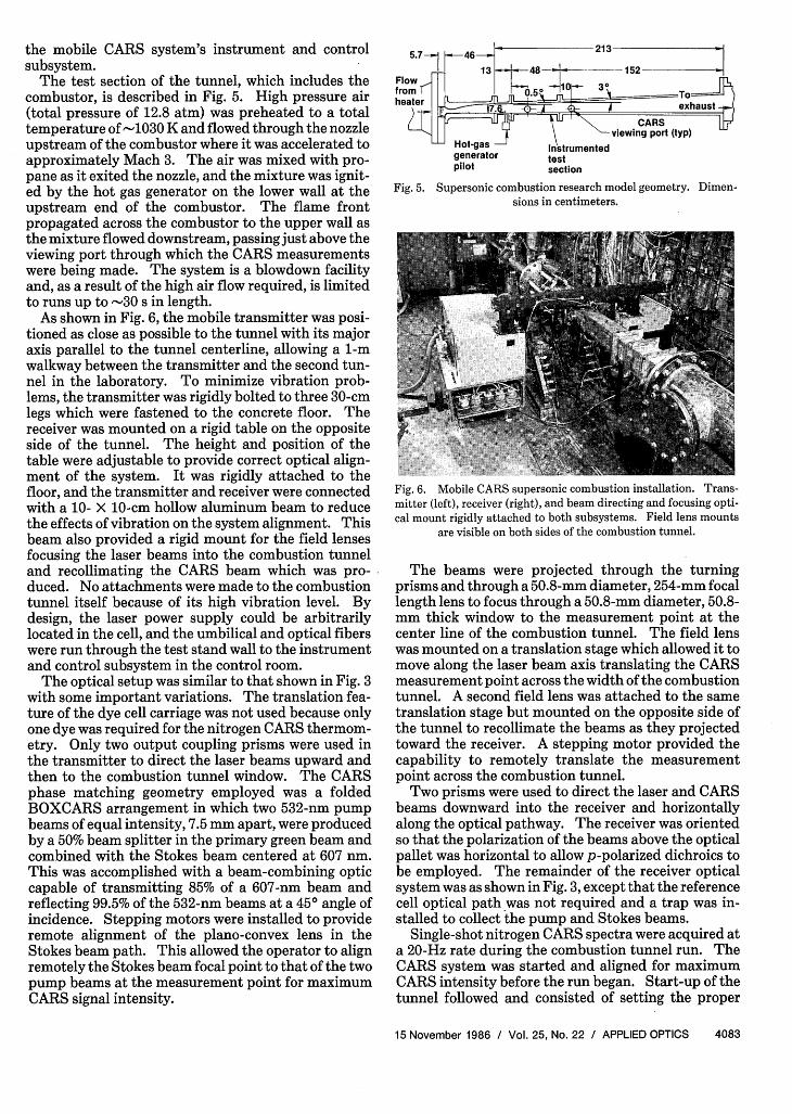
The test section of the tunnel, which includes thecombustor, is described in Fig. 5. High pressure air(total pressure of 12.8 atm) was preheated to a totaltemperature of -1030 K and flowed through the nozzleupstream of the combustor where it was accelerated toapproximately Mach 3. The air was mixed with pro-pane as it exited the nozzle, and the mixture was ignit-ed by the hot gas generator on the lower wall at theupstream end of the combustor. The flame frontpropagated across the combustor to the upper wall asthe mixture flowed downstream, passing just above theviewing port through which the CARS measurementswere being made. The system is a blowdown facilityand, as a result of the high air flow required, is limitedto runs up to -30 s in length.
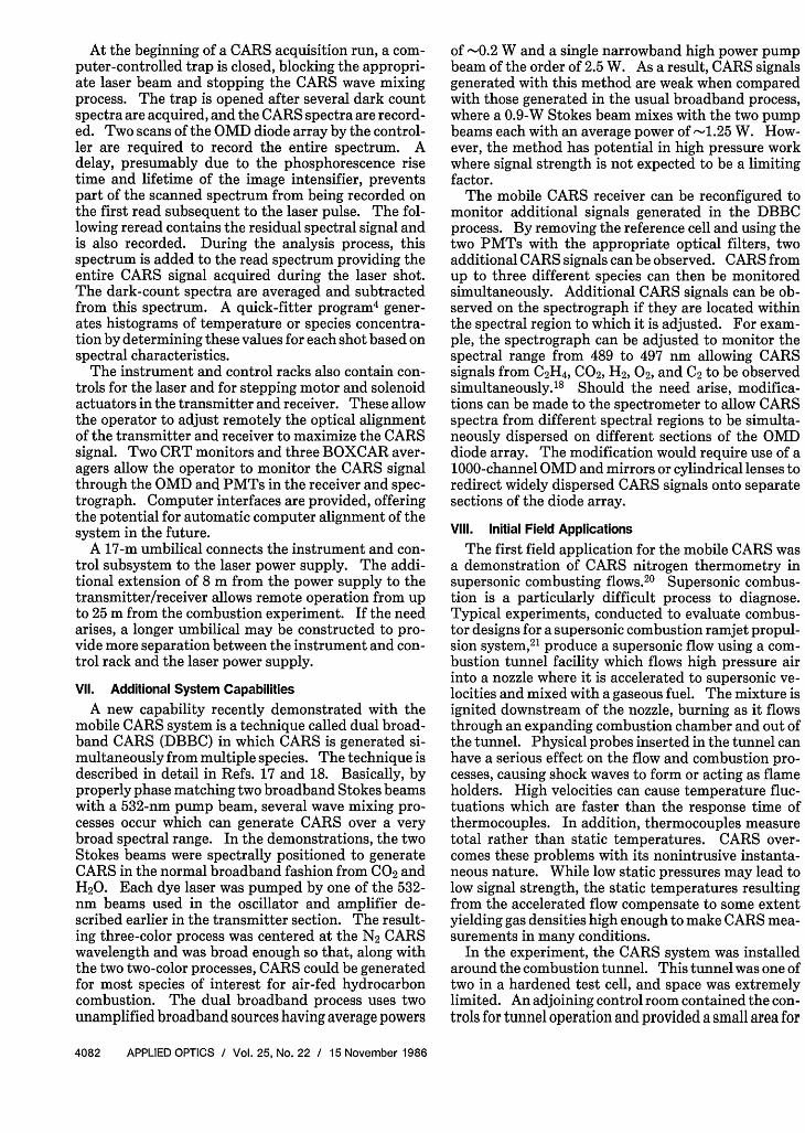
As shown in Fig. 6, the mobile transmitter was posi-tioned as close as possible to the tunnel with its majoraxis parallel to the tunnel centerline, allowing a 1-mwalkway between the transmitter and the second tun-nel in the laboratory. To minimize vibration prob-lems, the transmitter was rigidly bolted to three 30-cmlegs which were fastened to the concrete floor. Thereceiver was mounted on a rigid table on the oppositeside of the tunnel. The height and position of thetable were adjustable to provide correct optical align-ment of the system. It was rigidly attached to thefloor, and the transmitter and receiver were connectedwith a 10- X 10-cm hollow aluminum beam to reducethe effects of vibration on the system alignment. Thisbeam also provided a rigid mount for the field lensesfocusing the laser beams into the combustion tunneland recollimating the CARS beam which was pro-duced. No attachments were made to the combustiontunnel itself because of its high vibration level. Bydesign, the laser power supply could be arbitrarilylocated in the cell, and the umbilical and optical fiberswere run through the test stand wall to the instrumentand control subsystem in the control room.
The optical setup was similar to that shown in Fig. 3with some important variations. The translation fea-ture of the dye cell carriage was not used because onlyone dye was required for the nitrogen CARS thermom-etry. Only two output coupling prisms were used inthe transmitter to direct the laser beams upward andthen to the combustion tunnel window. The CARSphase matching geometry employed was a foldedBOXCARS arrangement in which two 532-nm pumpbeams of equal intensity, 7.5 mm apart, were producedby a 50% beam splitter in the primary green beam andcombined with the Stokes beam centered at 607 nm.This was accomplished with a beam-combining opticcapable of transmitting 85% of a 607-nm beam andreflecting 99.5% of the 532-nm beams at a 450 angle ofincidence. Stepping motors were installed to provideremote alignment of the plano-convex lens in theStokes beam path. This allowed the operator to alignremotely the Stokes beam focal point to that of the twopump beams at the measurement point for maximumCARS signal intensity.
generator te Ipilot section
Fig. 5. Supersonic combustion research model geometry.sions in centimeters.
Dimen-
Fig. 6. Mobile CARS supersonic combustion installation. Trans-mitter (left), receiver (right), and beam directing and focusing opti-cal mount rigidly attached to both subsystems. Field lens mounts
are visible on both sides of the combustion tunnel.
The beams were projected through the turningprisms and through a 50.8-mm diameter, 254-mm focallength lens to focus through a 50.8-mm diameter, 50.8-mm thick window to the measurement point at thecenter line of the combustion tunnel. The field lenswas mounted on a translation stage which allowed it tomove along the laser beam axis translating the CARSmeasurement point across the width of the combustiontunnel. A second field lens was attached to the sametranslation stage but mounted on the opposite side ofthe tunnel to recollimate the beams as they projectedtoward the receiver. A stepping motor provided thecapability to remotely translate the measurementpoint across the combustion tunnel.
Two prisms were used to direct the laser and CARSbeams downward into the receiver and horizontallyalong the optical pathway. The receiver was orientedso that the polarization of the beams above the opticalpallet was horizontal to allow p-polarized dichroics tobe employed. The remainder of the receiver opticalsystem was as shown in Fig. 3, except that the referencecell optical path was not required and a trap was in-stalled to collect the pump and Stokes beams.
Single-shot nitrogen CARS spectra were acquired ata 20-Hz rate during the combustion tunnel run. TheCARS system was started and aligned for maximumCARS intensity before the run began. Start-up of thetunnel followed and consisted of setting the proper
15 November 1986 / Vol. 25, No. 22 / APPLIED OPTICS 4083
I
Ut
0C,
300 400 500 600 700 800 900 1000 1100 1200STATIC TEMPERATURE - K
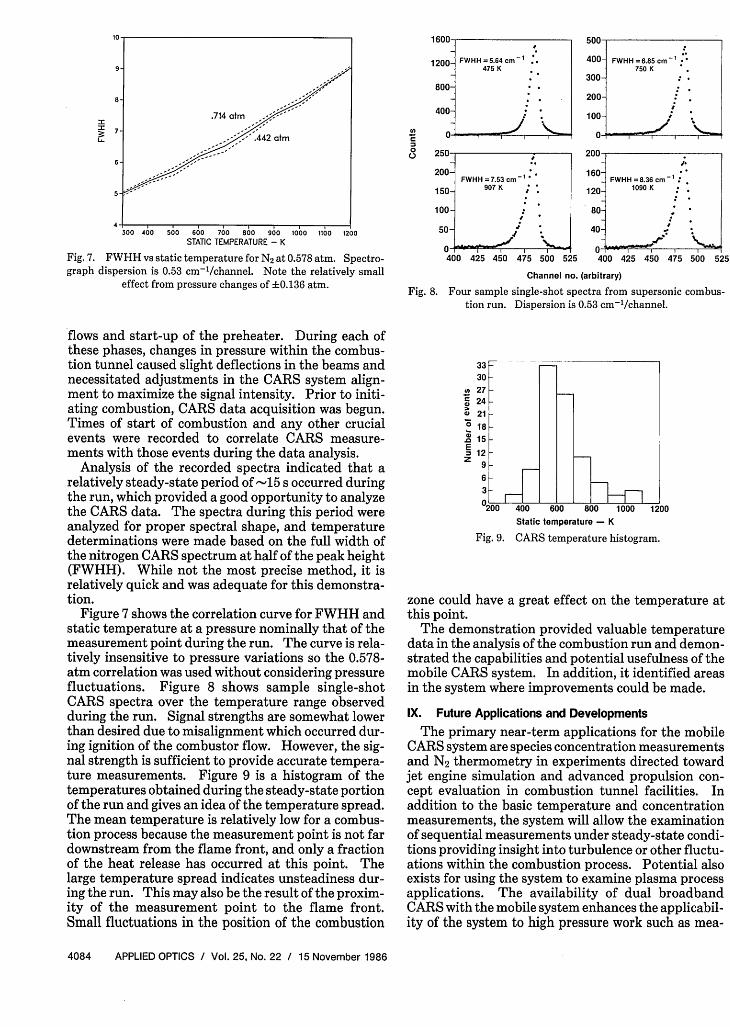
Fig. 7. FWHH vs static temperature for N2 at 0.578 atm. Spectro-graph dispersion is 0.53 cm-'/channel. Note the relatively small
effect from pressure changes of +0.136 atm.
I oUu-
1200- FWHH = 5.64 cm 1 t475 K
800-
400-
250-
200-FWHH = 7.53 cm
1-
150- 907 K
100-
50- ;
0- I 400 425 450 475 500 525
FWHH =6.85 cm 750 K
I I
I
400 2 4 4
400 425 4 475 500 525
Channel no. (arbitrary)
Fig. 8. Four sample single-shot spectra from supersonic combus-tion run. Dispersion is 0.53 cm'1/channel.
flows and start-up of the preheater. During each ofthese phases, changes in pressure within the combus-tion tunnel caused slight deflections in the beams andnecessitated adjustments in the CARS system align-ment to maximize the signal intensity. Prior to initi-ating combustion, CARS data acquisition was begun.Times of start of combustion and any other crucialevents were recorded to correlate CARS measure-ments with those events during the data analysis.
Analysis of the recorded spectra indicated that arelatively steady-state period of -15 s occurred duringthe run, which provided a good opportunity to analyzethe CARS data. The spectra during this period wereanalyzed for proper spectral shape, and temperaturedeterminations were made based on the full width ofthe nitrogen CARS spectrum at half of the peak height(FWHH). While not the most precise method, it isrelatively quick and was adequate for this demonstra-tion.
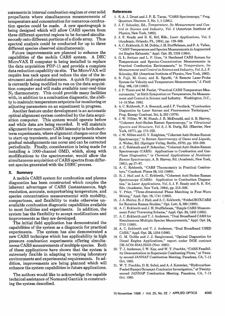
Figure 7 shows the correlation curve for FWHH andstatic temperature at a pressure nominally that of themeasurement point during the run. The curve is rela-tively insensitive to pressure variations so the 0.578-atm correlation was used without considering pressurefluctuations. Figure 8 shows sample single-shotCARS spectra over the temperature range observedduring the run. Signal strengths are somewhat lowerthan desired due to misalignment which occurred dur-ing ignition of the combustor flow. However, the sig-nal strength is sufficient to provide accurate tempera-ture measurements. Figure 9 is a histogram of thetemperatures obtained during the steady-state portionof the run and gives an idea of the temperature spread.The mean temperature is relatively low for a combus-tion process because the measurement point is not fardownstream from the flame front, and only a fractionof the heat release has occurred at this point. Thelarge temperature spread indicates unsteadiness dur-ing the run. This may also be the result of the proxim-ity of the measurement point to the flame front.Small fluctuations in the position of the combustion
(A2
a)0
.0
SEz
33 30 27 24 -21 -181512
9206_3_0!00
Fig. 9.
400 600 800 1000 12CStatic temperature - K
CARS temperature histogram.
IO
zone could have a great effect on the temperature atthis point.
The demonstration provided valuable temperaturedata in the analysis of the combustion run and demon-strated the capabilities and potential usefulness of themobile CARS system. In addition, it identified areasin the system where improvements could be made.
IX. Future Applications and Developments
The primary near-term applications for the mobileCARS system are species concentration measurementsand N2 thermometry in experiments directed towardjet engine simulation and advanced propulsion con-cept evaluation in combustion tunnel facilities. Inaddition to the basic temperature and concentrationmeasurements, the system will allow the examinationof sequential measurements under steady-state condi-tions providing insight into turbulence or other fluctu-ations within the combustion process. Potential alsoexists for using the system to examine plasma processapplications. The availability of dual broadbandCARS with the mobile system enhances the applicabil-ity of the system to high pressure work such as mea-
4084 APPLIED OPTICS / Vol. 25, No. 22 / 15 November 1986
400-
300-
200-
100-
160-
120-
80-
40-
FWHH =8.36 cm-':1090 K .
I'In)
. Sup . , , , , __
I.- .
. I
surements in internal combustion engines or over solidpropellants where simultaneous measurements oftemperature and concentration for numerous combus-tion species could be made. A new spectrograph isbeing designed which will allow CARS spectra fromthree different spectral regions to be focused simulta-neously onto different portions of a diode array. Thusspectral analysis could be conducted for up to threedifferent species observed simultaneously.
Future improvements are planned to enhance thecapabilities of the mobile CARS system. A DECMicroVAX II computer is being installed to replacethe data acquisition PDP-11 and provide a completedata reduction capability on site. The MicroVAX willrequire less rack space and reduce the size of the in-strument and control subsystem. A quick fit programis currently being modified to run on the data acquisi-tion computer and will make available near-real-timeN2 thermometry. This could provide many facilitieswith, in addition to a combustion diagnostic, the abili-ty to maintain temperature setpoints for monitoring oradjusting parameters on an experiment in progress.
Another feature under development is an automaticoptical alignment system controlled by the data acqui-sition computer. This system would operate beforeand while data are being recorded. It will maintainalignment for maximum CARS intensity in both short-term experiments, where alignment changes occur dueto start-up transients, and in long experiments wheregradual misalignments can occur and can be correctedperiodically. Finally, consideration is being made forinstalling a 1000-channel OMD, which, along withmodifications to the spectrometer, would allow thesimultaneous acquisition of CARS spectra from differ-ent species generated with the DBBC process.
X. Summary
A mobile CARS system for combustion and plasmadiagnostics has been constructed which couples theinherent advantages of CARS (instantaneous, highresolution, accurate, nonperturbing temperature, andspecies concentration measurements) with mobility,compactness, and flexibility to make otherwise un-available combustion diagnostic capabilities availableto most facilities and experiments. In addition, thesystem has the flexibility to accept modifications andimprovements as they are developed.
The initial field application has demonstrated thecapabilities of the system as a diagnostic for practicalexperiments. The system has also demonstrated anew CARS technique which has applicability in highpressure combustion experiments offering simulta-neous CARS measurements of multiple species. Bothof these applications have shown that the system isextremely flexible in adapting to varying laboratoryenvironments and experimental requirements. In ad-dition, improvements are being planned which willenhance the system capabilities in future applications.
The authors would like to acknowledge the capabletechnical assistance of Normand Gantick in construct-ing the system described.
References1. S. A. J. Druet and J. P. E. Taran, "CARS Spectroscopy," Prog.
Quantum Electron. 7, No. 1, 1 (1981).2. J. F. Schooley, Ed., Temperature, Its Measurement and Con-
trol in Science and Industry, Vol. 5 (American Institute ofPhysics, New York, 1982).
3. J. F. Ready and R. K. Erf, Eds., Laser Applications, Vol. 5(Academic, Orlando, FL, 1984), pp. 129-309.
4. A. C. Eckbreth, G. M. Dobbs, J. H. Stufflebeam, and P. A. Tellex,"CARS Temperature and Species Measurements in AugmentedJet Engine Exhausts," Appl. Opt. 23, 1328 (1984).
5. G. L. Switzer and L. P. Goss, "A Hardened CARS System forTemperature and Species-Concentration Measurements inPractical Combustion Environments," in Temperature, ItsMeasurement and Control in Science and Industry, Vol. 5, J. F.Schooley, Ed. (American Institute of Physics, New York, 1982).
6. S. Fujii, M. Gomi, and K. Eguchi, "A Remote Laser-ProbeSystem for Velocity and Temperature Measurements," J. FluidEng. 105, 128 (1983).
7. J. P. Taran and M. Pealat, "Practical CARS Temperature Mea-surements," at Sixth Symposium on Temperature, Its Measure-ment and Control in Science and Industry. Washington, D.C.,14-18 Mar. 1982.
8. A. C. Eckbreth, P. A. Bonczyk, and J. F. Verdieck, "CombustionDiagnostics by Laser Raman and Fluorescence Techniques,"Prog. Energy Combust. Sci. 5, 253 (1979).
9. J. W. Nibler, W. M. Shaub, J. R. McDonald, and A. B. Harvey,"Coherent Anti-Stokes Raman Spectroscopy," in VibrationalSpectra and Structure, Vol. 6, J. R. Durig, Ed. (Elsevier, NewYork, 1977), pp. 173-225.
10. J. W. Nibler and G. V. Knighten, "Coherent Anti-Stokes RamanSpectroscopy," in Raman Spectroscopy of Gases and Liquids,A. Weber, Ed. (Springer-Verlag, Berlin, 1979), pp. 253-299.
11. A. C. Eckbreth and P. Schreiber, "Coherent Anti-Stokes RamanSpectroscopy (CARS): Applications to Combustion and Gas-Phase Diagnostics," in Chemical Applications of NonlinearRaman Spectroscopy, A. B. Harvey, Ed. (Academic, New York,1981), pp 27-87.
12. A. C. Eckbreth, "CARS Thermometry in Practical Combus-tors," Combust. Flame 39, 133 (1980).
13. R. J. Hall and A. C. Eckbreth, "Coherent Anti-Stokes RamanSpectroscopy (CARS): Application to Combustion Diagnos-tics," in Laser Applications, Vol. 5, J. F. Ready and R. K. Erf,Eds. (Academic, New York, 1984), pp. 213-309.
14. Y. Prior, "Three-dimensional Phase Matching in Four-WaveMixing," Appl. Opt. 19, 1741 (1980).
15. J. A. Shirley, R. J. Hall, and A. C. Eckbreth, "Folded BOXCARSfor Rotation Raman Studies," Opt. Lett. 5, 380 (1980).
16. A. C. Eckbreth and J. H. Stufflebeam, "Simple CARS Measure-ment Point Traversing Scheme," Appl. Opt. 24, 1405 (1985).
17. A. C. Eckbreth and T. J. Anderson, "Dual Broadband CARS forSimultaneous Multiple Species Measurements," Appl. Opt. 24,2731 (1985).
18. A. C. Eckbreth and T. J. Anderson, "Dual Broadband USEDCARS," Appl. Opt. 25, 1534 (1986).
19. G. M. Dobbs and J. J. Sangiovanni, "Optical Diagnostics forDiesel Engine Applications," report under DOE contractDE-AC04-83AL23523 (Nov. 1985).
20. T. J. Anderson, I. W. Kay, and W. T. Peschke, "CARS Feasibil-ity Demonstration in Supersonic Combusting Flows," at Twen-ty-second JANNAF Combustion Meeting, Pasadena, CA, 7-11Oct. 1985.
21. W. T. Peschke, D. R. Sobel, and A. J. Karanian, "Hydrocarbon-Fueled Ramjet/Scramjet Combustor Investigation," at Twenty-second JANNAF Combustion Meeting, Pasadena, CA, 7-11Oct. 1985.
15 November 1986 / Vol. 25, No. 22 / APPLIED OPTICS 4085