mobile ad hoc networking carlos cordeiro & dharma...
TRANSCRIPT
1
1
Mobile Ad Hoc Networking
Carlos Cordeiro & Dharma AgrawalOBR Research Center for Distributed and Mobile Computing
University of Cincinnati – USA
http://www.ececs.uc.edu/[email protected]
2
Acknowledgments
g Some figures and slides were taken from Nitin Vaidya’s MobiCom’2000 tutorial

2
3
Course Outline
g Introductiong Unicast routingg Multicast routingg Medium Access Control g Sensor Networksg Standards activitiesg Open problems
4
Notes
g Only most important features of various schemes are typically discussediThe concepts covered here enable you to understand any
protocol
g Most schemes include many more details, and optimizationsiCourse handout has most details and references
3
5
Mobile Ad Hoc Networks (MANET)
Introduction and Generalities
6
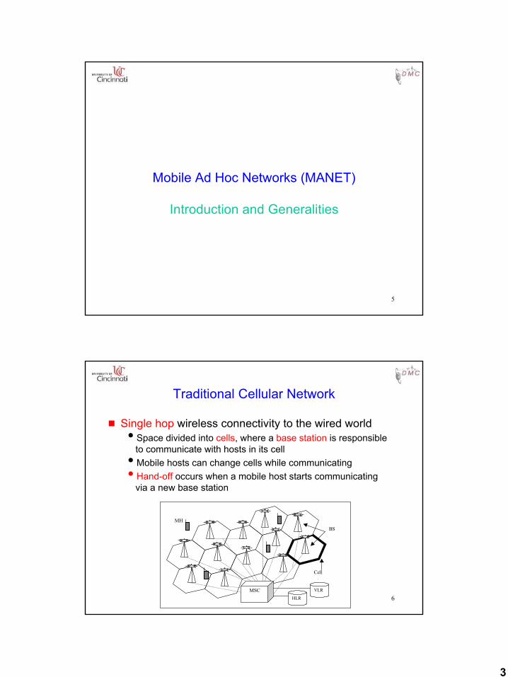
Traditional Cellular Network
g Single hop wireless connectivity to the wired worldiSpace divided into cells, where a base station is responsible
to communicate with hosts in its celliMobile hosts can change cells while communicatingiHand-off occurs when a mobile host starts communicating
via a new base station
MHBS
VLRMSCHLR
Cell
4
7
Mobile Ad hoc NETworks (MANET)
g Formed by wireless hosts which may be mobile
g Without (necessarily) using a pre-existing infrastructure
g Routes between nodes may potentially contain multiple hops
8
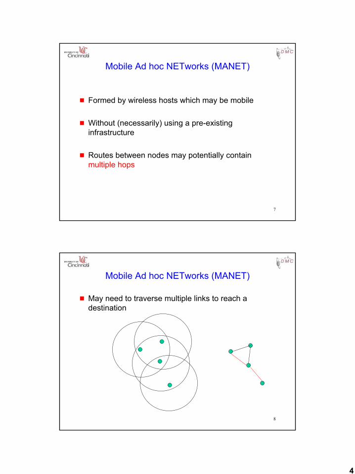
Mobile Ad hoc NETworks (MANET)
g May need to traverse multiple links to reach a destination
5
9
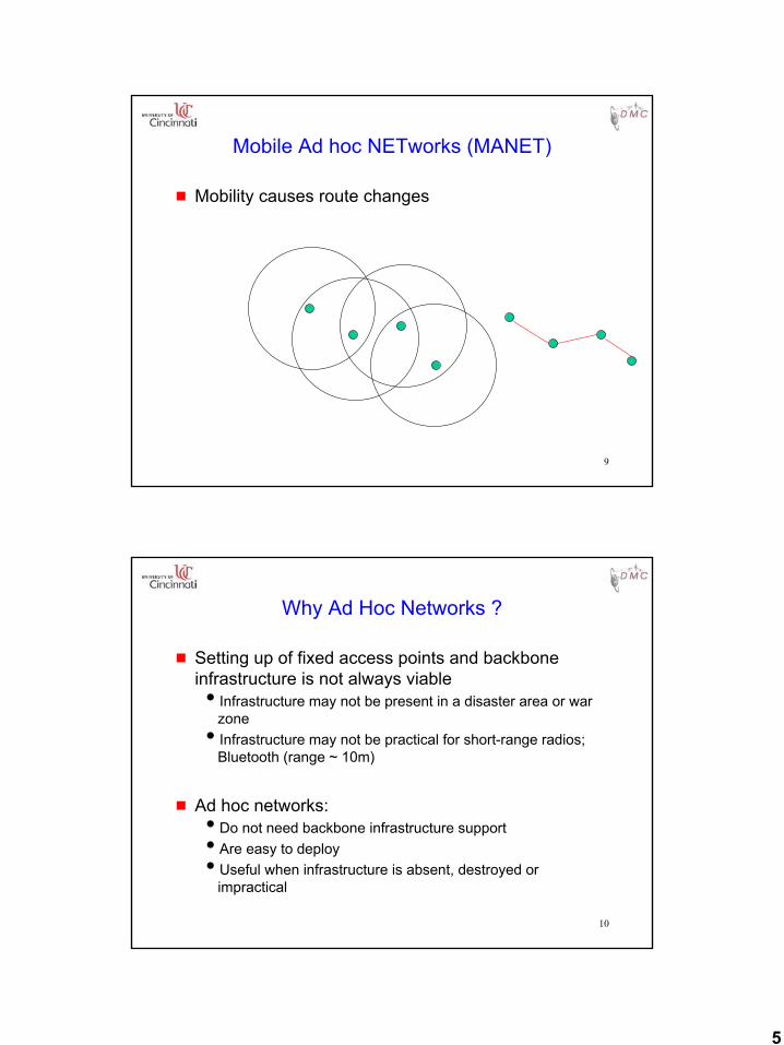
Mobile Ad hoc NETworks (MANET)
g Mobility causes route changes
10
Why Ad Hoc Networks ?
g Setting up of fixed access points and backbone infrastructure is not always viableiInfrastructure may not be present in a disaster area or war
zoneiInfrastructure may not be practical for short-range radios;
Bluetooth (range ~ 10m)
g Ad hoc networks:iDo not need backbone infrastructure supportiAre easy to deployiUseful when infrastructure is absent, destroyed or
impractical
6
11
Many Applications
g Personal area networking (PAN)icell phone, laptop, ear phone, wrist watch
g Military environmentsisoldiers, tanks, planes
g Civilian environmentsitaxi cab networkimeeting roomsisports stadiumsiboats, small aircraft
g Emergency operationsisearch-and-rescueipolicing and fire fighting
12
Challenges in Mobile Environments
g Limitations of the Wireless Networkipacket loss due to transmission errorsivariable capacity linksifrequent disconnections/partitionsilimited communication bandwidth ibroadcast nature of the communications
g Limitations Imposed by Mobilityidynamically changing topologies/routesilack of mobility awareness by system/applications
g Limitations of the Mobile Computerishort battery lifetimeilimited capacities
7
13
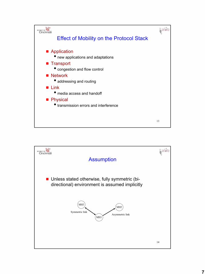
Effect of Mobility on the Protocol Stack
g Applicationinew applications and adaptations
g Transporticongestion and flow control
g Networkiaddressing and routing
g Linkimedia access and handoff
g Physicalitransmission errors and interference
14
Assumption
g Unless stated otherwise, fully symmetric (bi-directional) environment is assumed implicitly
MH3
MH1
MH2
Symmetric linkAsymmetric link
8
15
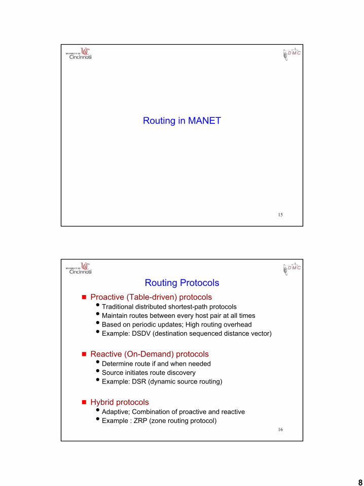
Routing in MANET
16
Routing Protocolsg Proactive (Table-driven) protocolsiTraditional distributed shortest-path protocolsiMaintain routes between every host pair at all timesiBased on periodic updates; High routing overheadiExample: DSDV (destination sequenced distance vector)
g Reactive (On-Demand) protocolsiDetermine route if and when needediSource initiates route discoveryiExample: DSR (dynamic source routing)
g Hybrid protocolsiAdaptive; Combination of proactive and reactiveiExample : ZRP (zone routing protocol)
9
17
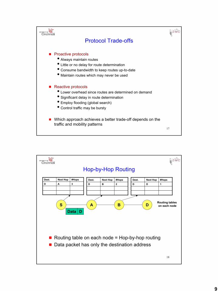
Protocol Trade-offs
g Proactive protocolsiAlways maintain routesiLittle or no delay for route determinationiConsume bandwidth to keep routes up-to-dateiMaintain routes which may never be used
g Reactive protocolsiLower overhead since routes are determined on demandiSignificant delay in route determinationiEmploy flooding (global search)iControl traffic may be bursty
g Which approach achieves a better trade-off depends on the traffic and mobility patterns
18
Hop-by-Hop Routing
g Routing table on each node = Hop-by-hop routingg Data packet has only the destination address
3AD
#HopsNext HopDest.
2BD
#HopsNext HopDest.
1DD
#HopsNext HopDest.
S A B DRouting tables on each node
Data D
10
19
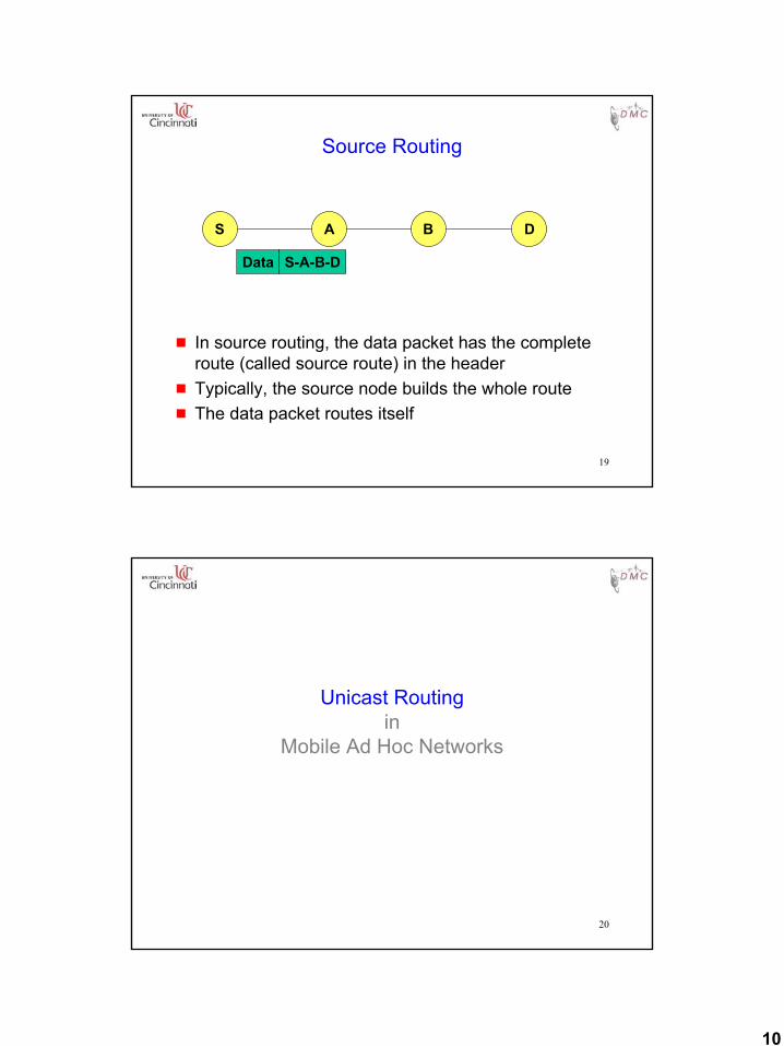
Source Routing
g In source routing, the data packet has the complete route (called source route) in the header
g Typically, the source node builds the whole routeg The data packet routes itself
S A B D
Data S-A-B-D
20
Unicast Routingin
Mobile Ad Hoc Networks
11
21
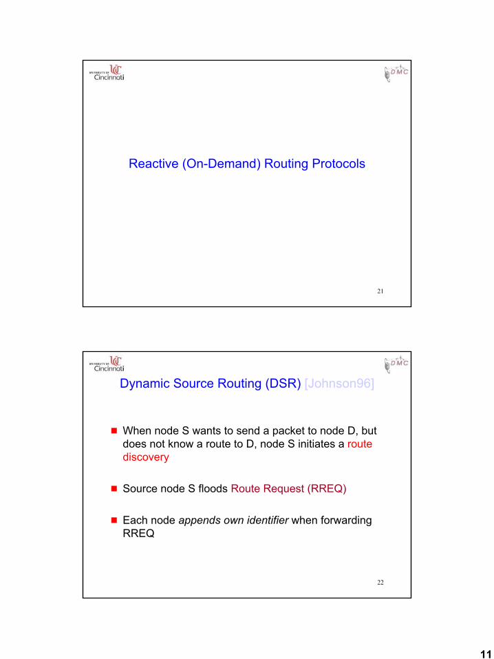
Reactive (On-Demand) Routing Protocols
22
Dynamic Source Routing (DSR) [Johnson96]
g When node S wants to send a packet to node D, but does not know a route to D, node S initiates a route discovery
g Source node S floods Route Request (RREQ)
g Each node appends own identifier when forwarding RREQ
12
23
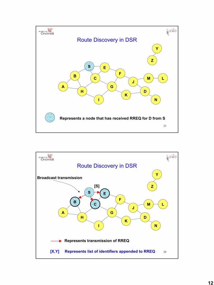
Route Discovery in DSR
B
A
S EF
H
J
D
C
G
IK
Z
Y
Represents a node that has received RREQ for D from S
M
N
L
24
Route Discovery in DSR
B
A
S EF
H
J
D
C
G
IK
Represents transmission of RREQ
Z
YBroadcast transmission
M
N
L
[S]
[X,Y] Represents list of identifiers appended to RREQ
13
25
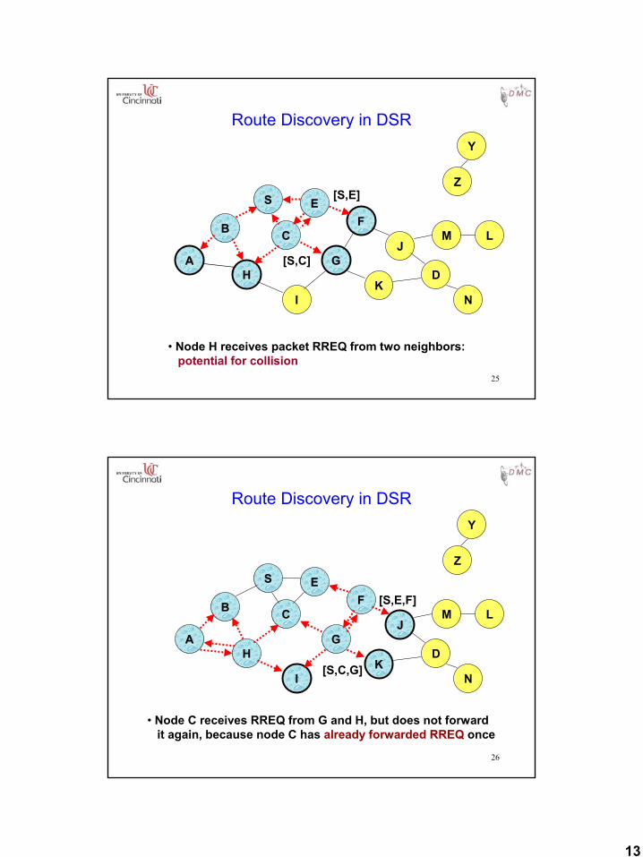
Route Discovery in DSR
B
A
S EF
H
J
D
C
G
IK
• Node H receives packet RREQ from two neighbors:potential for collision
Z
Y
M
N
L
[S,E]
[S,C]
26
Route Discovery in DSR
B
A
S EF
H
J
D
C
G
IK
• Node C receives RREQ from G and H, but does not forwardit again, because node C has already forwarded RREQ once
Z
Y
M
N
L
[S,C,G]
[S,E,F]
14
27
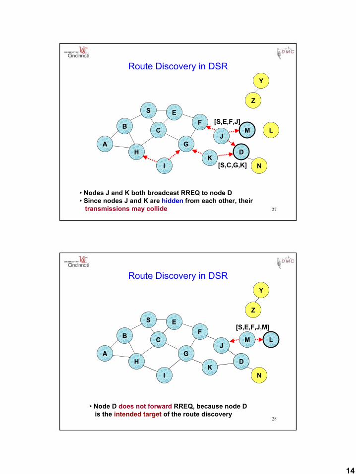
Route Discovery in DSR
B
A
S EF
H
J
D
C
G
IK
Z
Y
M
• Nodes J and K both broadcast RREQ to node D• Since nodes J and K are hidden from each other, their
transmissions may collide
N
L
[S,C,G,K]
[S,E,F,J]
28
Route Discovery in DSR
B
A
S EF
H
J
D
C
G
IK
Z
Y
• Node D does not forward RREQ, because node Dis the intended target of the route discovery
M
N
L
[S,E,F,J,M]
15
29
Route Discovery in DSR
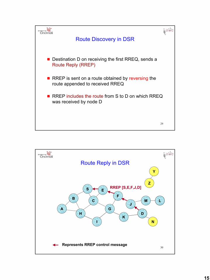
g Destination D on receiving the first RREQ, sends a Route Reply (RREP)
g RREP is sent on a route obtained by reversing the route appended to received RREQ
g RREP includes the route from S to D on which RREQ was received by node D
30
Route Reply in DSR
B
A
S EF
H
J
D
C
G
IK
Z
Y
M
N
L
RREP [S,E,F,J,D]
Represents RREP control message
16
31
Dynamic Source Routing (DSR)
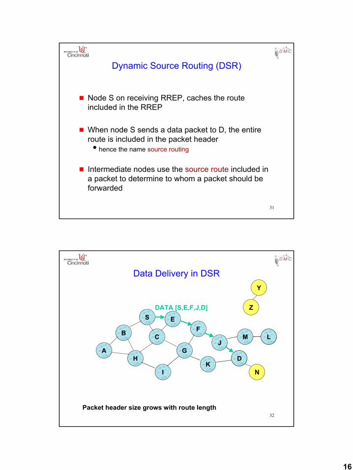
g Node S on receiving RREP, caches the route included in the RREP
g When node S sends a data packet to D, the entire route is included in the packet headerihence the name source routing
g Intermediate nodes use the source route included in a packet to determine to whom a packet should be forwarded
32
Data Delivery in DSR
B
A
S EF
H
J
D
C
G
IK
Z
Y
M
N
L
DATA [S,E,F,J,D]
Packet header size grows with route length
17
33
DSR Optimization: Route Caching
g Each node caches a new route it learns by any means
g When node S finds route [S,E,F,J,D] to node D, node S also learns route [S,E,F] to node F
g When node K receives Route Request [S,C,G] destined for node D, node K learns route [K,G,C,S] to node S
g When node F forwards Route Reply RREP[S,E,F,J,D], node F learns route [F,J,D] to node D
g When node E forwards Data [S,E,F,J,D] it learns route [E,F,J,D] to node D
g A node may also learn a route when it overhears Data
g Problem: Stale caches may increase overheads
34
Dynamic Source Routing: Advantages
g Routes maintained only between nodes who need to communicateireduces overhead of route maintenance
g Route caching can further reduce route discovery overhead
g A single route discovery may yield many routes to the destination, due to intermediate nodes replying from local caches
18
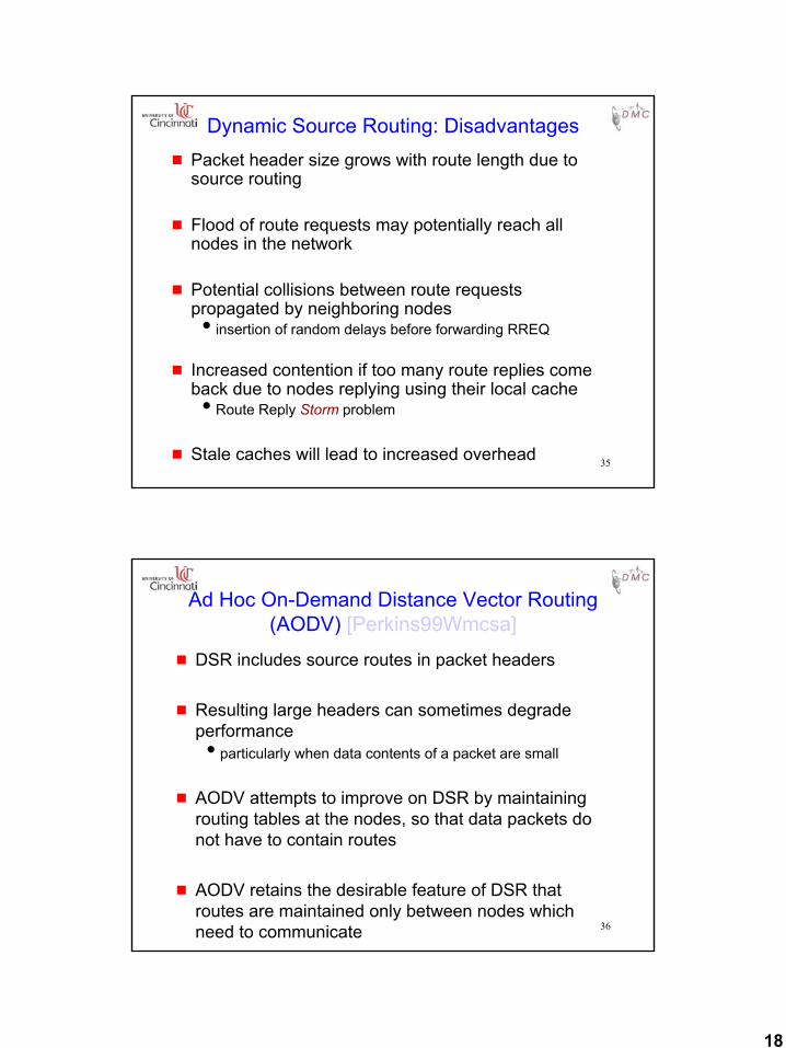
35
Dynamic Source Routing: Disadvantagesg Packet header size grows with route length due to
source routing
g Flood of route requests may potentially reach all nodes in the network
g Potential collisions between route requests propagated by neighboring nodesiinsertion of random delays before forwarding RREQ
g Increased contention if too many route replies come back due to nodes replying using their local cacheiRoute Reply Storm problem
g Stale caches will lead to increased overhead
36
Ad Hoc On-Demand Distance Vector Routing (AODV) [Perkins99Wmcsa]
g DSR includes source routes in packet headers
g Resulting large headers can sometimes degrade performanceiparticularly when data contents of a packet are small
g AODV attempts to improve on DSR by maintaining routing tables at the nodes, so that data packets do not have to contain routes
g AODV retains the desirable feature of DSR that routes are maintained only between nodes which need to communicate
19
37
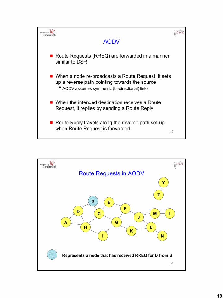
AODV
g Route Requests (RREQ) are forwarded in a manner similar to DSR
g When a node re-broadcasts a Route Request, it sets up a reverse path pointing towards the sourceiAODV assumes symmetric (bi-directional) links
g When the intended destination receives a Route Request, it replies by sending a Route Reply
g Route Reply travels along the reverse path set-up when Route Request is forwarded
38
Route Requests in AODV
B
A
S EF
H
J
D
C
G
IK
Z
Y
Represents a node that has received RREQ for D from S
M
N
L
20
39
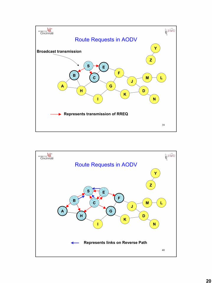
Route Requests in AODV
B
A
S EF
H
J
D
C
G
IK
Represents transmission of RREQ
Z
YBroadcast transmission
M
N
L
40
Route Requests in AODV
B
A
S EF
H
J
D
C
G
IK
Represents links on Reverse Path
Z
Y
M
N
L
21
41
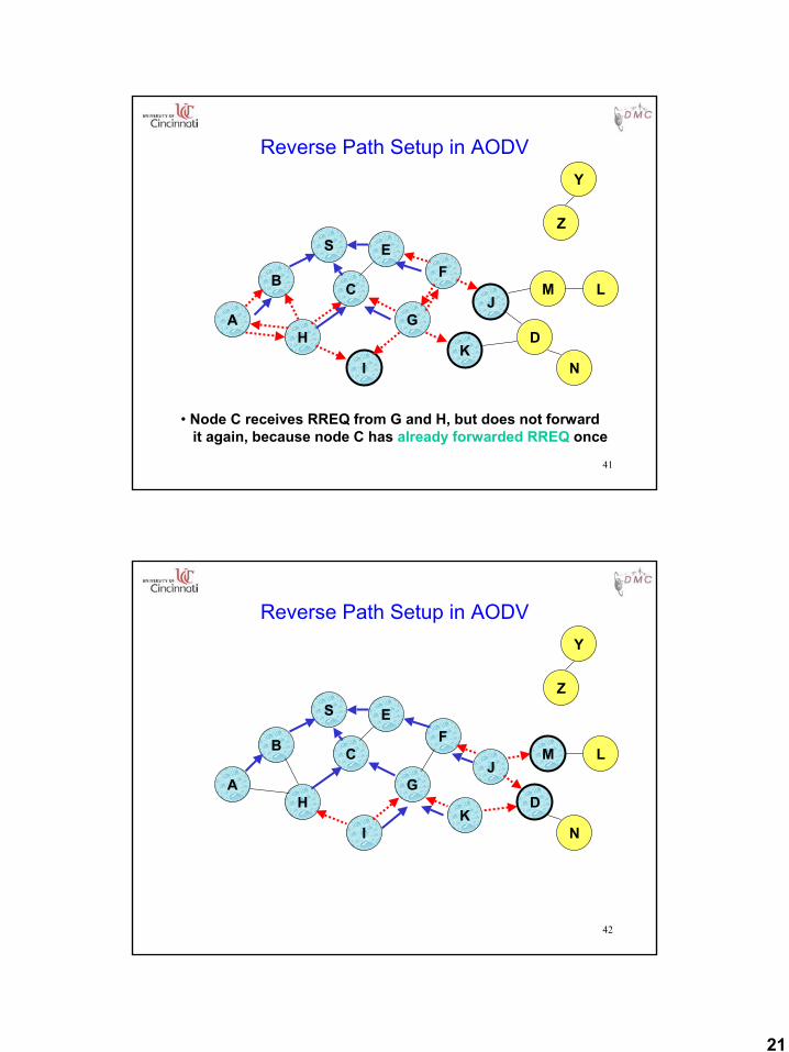
Reverse Path Setup in AODV
B
A
S EF
H
J
D
C
G
IK
• Node C receives RREQ from G and H, but does not forwardit again, because node C has already forwarded RREQ once
Z
Y
M
N
L
42
Reverse Path Setup in AODV
B
A
S EF
H
J
D
C
G
IK
Z
Y
M
N
L
22
43
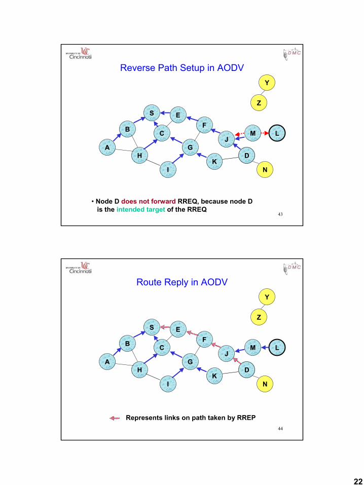
Reverse Path Setup in AODV
B
A
S EF
H
J
D
C
G
IK
Z
Y
• Node D does not forward RREQ, because node Dis the intended target of the RREQ
M
N
L
44
Route Reply in AODV
B
A
S EF
H
J
D
C
G
IK
Z
Y
Represents links on path taken by RREP
M
N
L
23
45
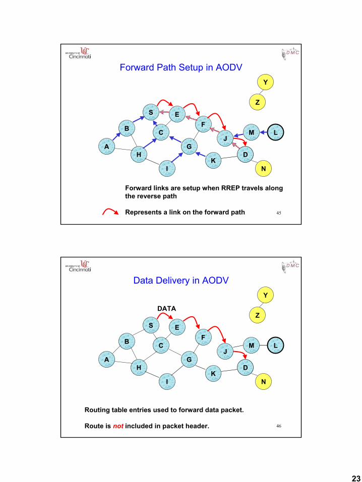
Forward Path Setup in AODV
B
A
S EF
H
J
D
C
G
IK
Z
Y
M
N
L
Forward links are setup when RREP travels alongthe reverse path
Represents a link on the forward path
46
Data Delivery in AODV
B
A
S EF
H
J
D
C
G
IK
Z
Y
M
N
L
Routing table entries used to forward data packet.
Route is not included in packet header.
DATA
24
47
Timeouts
g A routing table entry maintaining a reverse path is purged after a timeout intervalitimeout should be long enough to allow RREP to come back
g A routing table entry maintaining a forward path is purged if not used for a active_route_timeout intervaliif no is data being sent using a particular routing table entry,
that entry will be deleted from the routing table (even if the route may actually still be valid)
48
Link Failure Detection
g Hello messages: Neighboring nodes periodically exchange hello message
g Absence of hello message is used as an indication of link failureiWhen node X is unable to forward packet P (from node S to
node D) on link (X,Y), it generates a RERR message
g Alternatively, failure to receive several MAC-level acknowledgement may be used as an indication of link failure
25
49
Summary: AODV
g Routes need not be included in packet headers
g Nodes maintain routing tables containing entries only for routes that are in active use
g At most one next-hop per destination maintained at each nodeiDSR may maintain several routes for a single destination
50
Flooding of Control Packets
g How to reduce the scope of the route request flood ?iLAR [Ko98Mobicom]iQuery localization [Castaneda99Mobicom]
g How to reduce redundant broadcasts ?iThe Broadcast Storm Problem [Ni99Mobicom]iMore to come in subsequent slides …
26
51
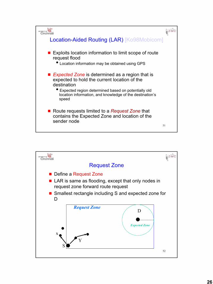
Location-Aided Routing (LAR) [Ko98Mobicom]
g Exploits location information to limit scope of route request floodiLocation information may be obtained using GPS
g Expected Zone is determined as a region that is expected to hold the current location of the destinationiExpected region determined based on potentially old
location information, and knowledge of the destination’s speed
g Route requests limited to a Request Zone that contains the Expected Zone and location of the sender node
52
Request Zoneg Define a Request Zoneg LAR is same as flooding, except that only nodes in
request zone forward route requestg Smallest rectangle including S and expected zone for
D
S
Request ZoneD
Expected Zone
xY
27
53
Location Aided Routing (LAR)
g Advantagesireduces the scope of route request floodireduces overhead of route discovery
g DisadvantagesiNodes need to know their physical locationsiDoes not take into account possible existence of
obstructions for radio transmissions
54
So far ...
g All protocols discussed so far perform some form of flooding
g Now we will consider protocols which try to reduce/avoid such behavior
28
55
Link Reversal Algorithm [Gafni81]
A FB
C E G
D
56
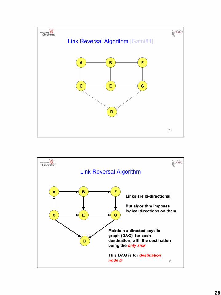
Link Reversal Algorithm
A FB
C E G
D
Maintain a directed acyclic graph (DAG) for each destination, with the destinationbeing the only sink
This DAG is for destination node D
Links are bi-directional
But algorithm imposeslogical directions on them
29
57
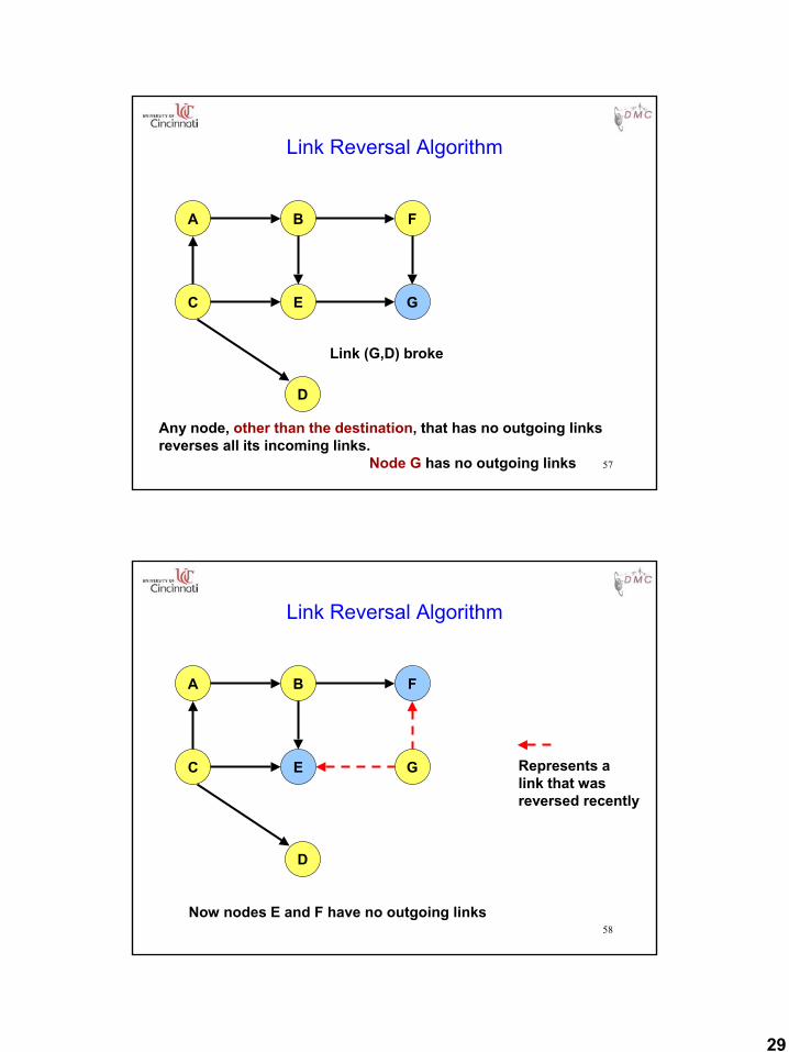
Link Reversal Algorithm
Link (G,D) broke
A FB
C E G
D
Any node, other than the destination, that has no outgoing linksreverses all its incoming links.
Node G has no outgoing links
58
Link Reversal Algorithm
A FB
C E G
D
Now nodes E and F have no outgoing links
Represents alink that wasreversed recently
30
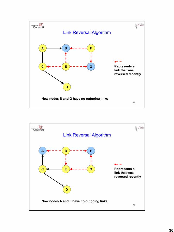
59
Link Reversal Algorithm
A FB
C E G
D
Now nodes B and G have no outgoing links
Represents alink that wasreversed recently
60
Link Reversal Algorithm
A FB
C E G
D
Now nodes A and F have no outgoing links
Represents alink that wasreversed recently
31
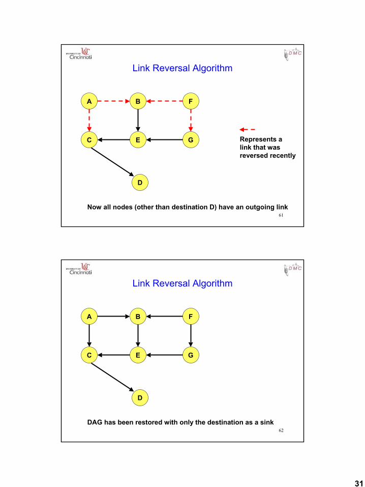
61
Link Reversal Algorithm
A FB
C E G
D
Now all nodes (other than destination D) have an outgoing link
Represents alink that wasreversed recently
62
Link Reversal Algorithm
A FB
C E G
D
DAG has been restored with only the destination as a sink
32
63
Link Reversal Algorithm
g Attempts to keep link reversals local to where the failure occurrediBut this is not guaranteed
g When the first packet is sent to a destination, the destination oriented DAG is constructed
g The initial construction does result in flooding of control packets
64
Link Reversal Algorithm
g The previous algorithm is called a full reversal method since when a node reverses links, it reverses all its incoming links
g Partial reversal method [Gafni81]: A node reverses incoming links from only those neighbors who have not themselves reversed links “previously”iIf all neighbors have reversed links, then the node reverses
all its incoming linksi“Previously” at node X means since the last link reversal
done by node X
33
65
Link Reversal Methods
g AdvantagesiLink reversal methods attempt to limit updates to routing
tables at nodes in the vicinity of a broken link• Partial reversal method tends to be better than full
reversal methodiEach node may potentially have multiple routes to a
destination (multipath)
g DisadvantagesiNeed a mechanism to detect link failure
• hello messages may be usediIf network is partitioned, link reversals continue indefinitely
66
Temporally-Ordered Routing Algorithm(TORA) [Park97Infocom]
g Route optimality is considered of secondary importance; longer routes may be used
g At each node, a logically separate copy of TORA is run for each destination, that computes the height of the node with respect to the destinationiHeight captures number of hops and next hop
g Route discovery is by using query and update packets
g TORA modifies the partial link reversal method to be able to detect partitions
g When a partition is detected, all nodes in the partition are informed, and link reversals in that partition cease
34
67
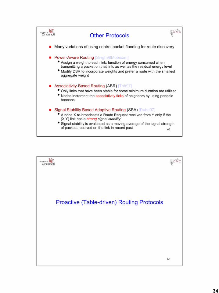
Other Protocols
g Many variations of using control packet flooding for route discovery
g Power-Aware Routing [Singh98Mobicom]iAssign a weight to each link: function of energy consumed when
transmitting a packet on that link, as well as the residual energy leveliModify DSR to incorporate weights and prefer a route with the smallest
aggregate weight
g Associativity-Based Routing (ABR) [Toh97]iOnly links that have been stable for some minimum duration are utilizediNodes increment the associativity ticks of neighbors by using periodic
beacons
g Signal Stability Based Adaptive Routing (SSA) [Dube97]iA node X re-broadcasts a Route Request received from Y only if the
(X,Y) link has a strong signal stabilityiSignal stability is evaluated as a moving average of the signal strength
of packets received on the link in recent past
68
Proactive (Table-driven) Routing Protocols
35
69
Broad Classification of Proactive Protocols
g Distance-Vector basediDSDV (Destination-Sequenced Distance-Vector)
g Link-State basediTBRPF (Topology Broadcast with Reverse Path Forwarding)iOLSR (Optimized Link-State Routing)
70
Destination-Sequenced Distance-Vector (DSDV) [Perkins94Sigcomm]
g Each node maintains a routing table which storesinext hop towards each destinationia cost metric for the path to each destinationia destination sequence number that is created by the
destination itselfiSequence numbers used to avoid formation of loops
(indicate freshness of routes)
g Each node periodically forwards the routing table to its neighborsiEach node increments and appends its sequence number
when sending its local routing tableiThis sequence number will be attached to route entries
created for this node
36
71
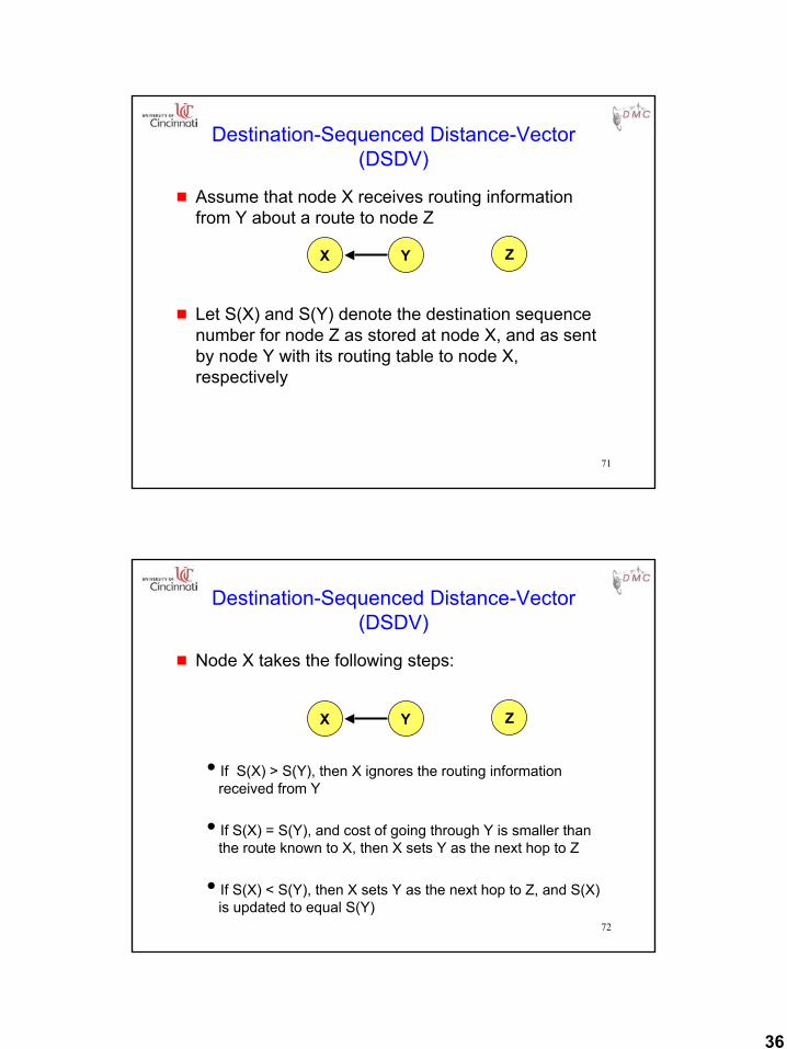
Destination-Sequenced Distance-Vector (DSDV)
g Assume that node X receives routing information from Y about a route to node Z
g Let S(X) and S(Y) denote the destination sequence number for node Z as stored at node X, and as sent by node Y with its routing table to node X, respectively
X Y Z
72
Destination-Sequenced Distance-Vector (DSDV)
g Node X takes the following steps:
iIf S(X) > S(Y), then X ignores the routing information received from Y
iIf S(X) = S(Y), and cost of going through Y is smaller than the route known to X, then X sets Y as the next hop to Z
iIf S(X) < S(Y), then X sets Y as the next hop to Z, and S(X) is updated to equal S(Y)
X Y Z
37
73
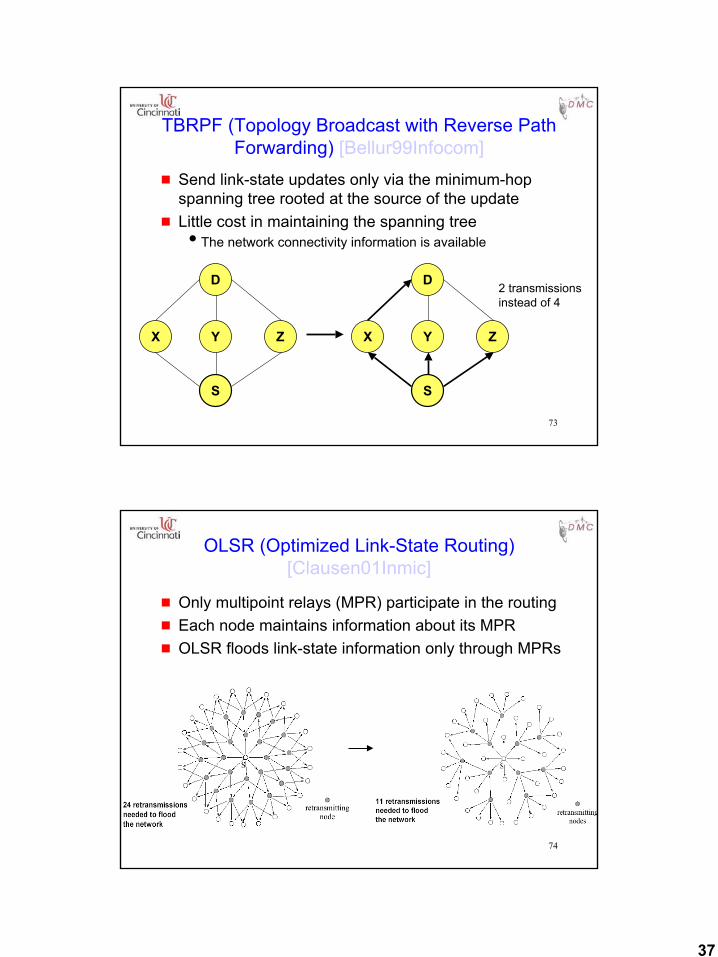
TBRPF (Topology Broadcast with Reverse Path Forwarding) [Bellur99Infocom]
g Send link-state updates only via the minimum-hop spanning tree rooted at the source of the update
g Little cost in maintaining the spanning treeiThe network connectivity information is available
X Y Z
S
D
X Y Z
S
D 2 transmissions instead of 4
74
OLSR (Optimized Link-State Routing) [Clausen01Inmic]
g Only multipoint relays (MPR) participate in the routingg Each node maintains information about its MPRg OLSR floods link-state information only through MPRs
38
75
Hybrid Routing Protocols
76
Zone Routing Protocol (ZRP) [Haas98]
g ZRP combines proactive and reactive approachesiMore like a framework
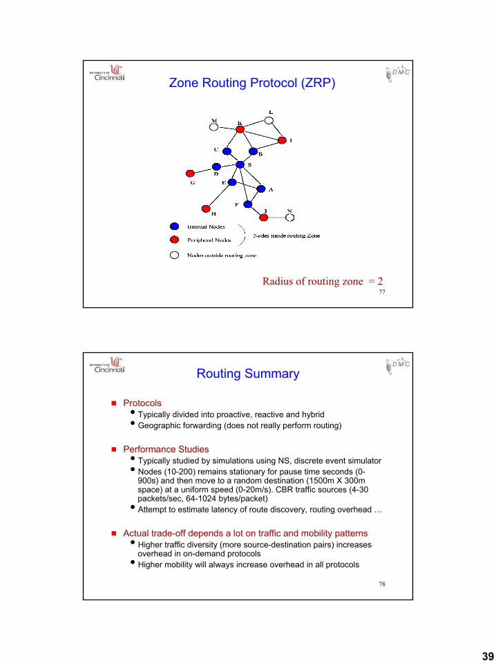
g All nodes within hop distance at most d from a node X are said to be in the routing zone of node X
g All nodes at hop distance exactly d are said to beperipheral nodes of node X’s routing zone
g Intra-zone routing: Proactively maintain routes to all nodes within the source node’s own zone.
g Inter-zone routing: Use an on-demand protocol (similar to DSR or AODV) to determine routes to outside zone.
39
77
Zone Routing Protocol (ZRP)
Radius of routing zone = 2
78
Routing Summary
g ProtocolsiTypically divided into proactive, reactive and hybrid iGeographic forwarding (does not really perform routing)
g Performance StudiesiTypically studied by simulations using NS, discrete event simulatoriNodes (10-200) remains stationary for pause time seconds (0-
900s) and then move to a random destination (1500m X 300m space) at a uniform speed (0-20m/s). CBR traffic sources (4-30 packets/sec, 64-1024 bytes/packet)iAttempt to estimate latency of route discovery, routing overhead …
g Actual trade-off depends a lot on traffic and mobility patternsiHigher traffic diversity (more source-destination pairs) increases
overhead in on-demand protocolsiHigher mobility will always increase overhead in all protocols
40
79
Other Routing Protocols
g Plenty of other routing protocols
g Discussion here is far from exhaustive
g Course handout contains descriptions (references) of some other protocols
80
Multicast Routingin
Mobile Ad Hoc Networks
41
81
Multicasting
g A multicast group is defined with a unique group identifier
g Nodes may join or leave the multicast group anytime
g In traditional networks, the physical network topology does not change often
g In MANET, the physical topology can change often
82
Multicasting in MANET
g Need to take topology change into account when designing a multicast protocol
g Several new protocols have been proposed for multicasting in MANETiAODV MulticastiODMRPiFlooding, AMRoute, CAMP, AMRIS, …
42
83
AODV Multicasting [Royer00Mobicom]
g Each multicast group has a group leader
g Group leader is responsible for maintaining group sequence number (which is used to ensure freshness of routing information)iSimilar to sequence numbers for AODV unicast
g First node joining a group becomes group leader
g A node on becoming a group leader, broadcasts a Group Hello message
84
AODV Group Sequence Number
g In our illustrations, we will ignore the group sequence numbers
g However, note that a node makes use of information received only with recent enough sequence number
43
85
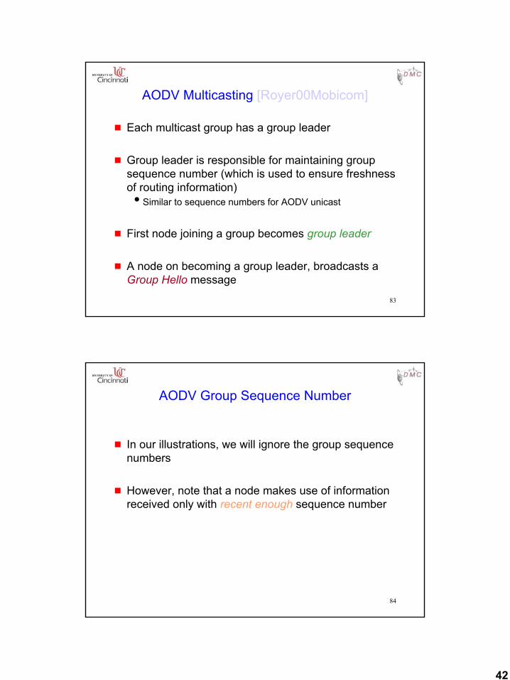
AODV Multicast Tree
EL
H
J
D
C
G
AK
NGroup and multicast tree member
Tree (but not group) member
Group leader
B
Multicast tree links
86
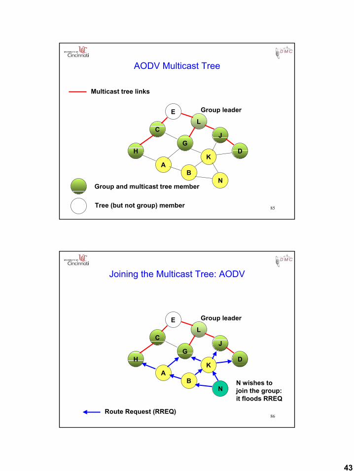
Joining the Multicast Tree: AODV
EL
H
J
D
C
G
AK
N
Group leader
B N wishes tojoin the group:it floods RREQ
Route Request (RREQ)
44
87
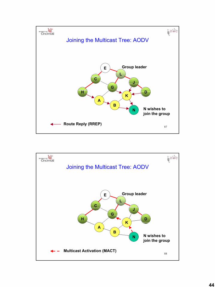
Joining the Multicast Tree: AODV
EL
H
J
D
C
G
AK
N
Group leader
BN wishes tojoin the group
Route Reply (RREP)
88
Joining the Multicast Tree: AODV
EL
H
J
D
C
G
AK
N
Group leader
BN wishes tojoin the group
Multicast Activation (MACT)
45
89
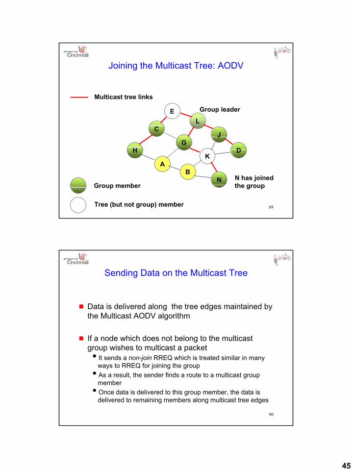
Joining the Multicast Tree: AODV
EL
H
J
D
C
G
AK
N
Group leader
BN has joinedthe group
Multicast tree links
Group member
Tree (but not group) member
90
Sending Data on the Multicast Tree
g Data is delivered along the tree edges maintained by the Multicast AODV algorithm
g If a node which does not belong to the multicast group wishes to multicast a packetiIt sends a non-join RREQ which is treated similar in many
ways to RREQ for joining the groupiAs a result, the sender finds a route to a multicast group
memberiOnce data is delivered to this group member, the data is
delivered to remaining members along multicast tree edges
46
91
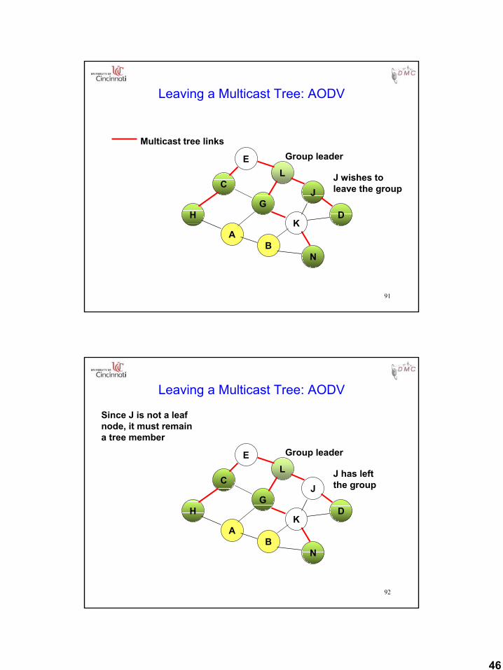
Leaving a Multicast Tree: AODV
EL
H
J
D
C
G
A
Group leader
B
J wishes toleave the group
Multicast tree links
K
N
92
Leaving a Multicast Tree: AODV
EL
H
J
D
C
G
A
Group leader
B
J has leftthe group
Since J is not a leafnode, it must remaina tree member
K
N
47
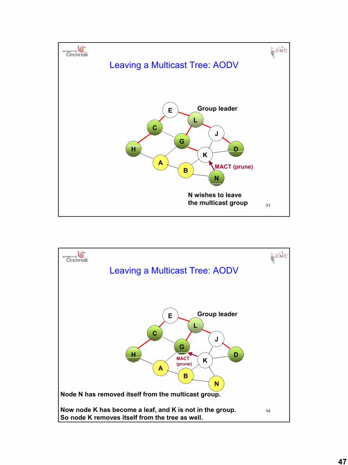
93
Leaving a Multicast Tree: AODV
EL
H
J
D
C
G
A
Group leader
B
K
N
N wishes to leavethe multicast group
MACT (prune)
94
Leaving a Multicast Tree: AODV
EL
H
J
D
C
G
A
Group leader
B
K
N
MACT(prune)
Node N has removed itself from the multicast group.
Now node K has become a leaf, and K is not in the group.So node K removes itself from the tree as well.
48
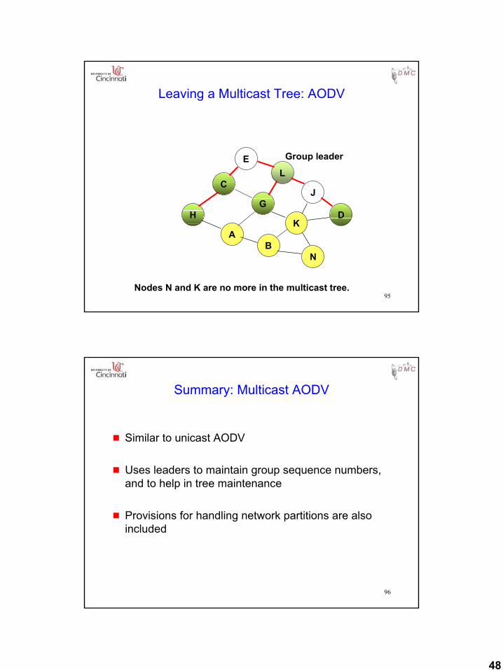
95
Leaving a Multicast Tree: AODV
EL
H
J
D
C
G
A
Group leader
B
K
N
Nodes N and K are no more in the multicast tree.
96
Summary: Multicast AODV
g Similar to unicast AODV
g Uses leaders to maintain group sequence numbers, and to help in tree maintenance
g Provisions for handling network partitions are also included
49
97
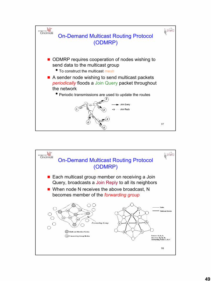
On-Demand Multicast Routing Protocol (ODMRP)
g ODMRP requires cooperation of nodes wishing to send data to the multicast groupiTo construct the multicast mesh
g A sender node wishing to send multicast packets periodically floods a Join Query packet throughout the networkiPeriodic transmissions are used to update the routes
98
On-Demand Multicast Routing Protocol (ODMRP)
g Each multicast group member on receiving a Join Query, broadcasts a Join Reply to all its neighbors
g When node N receives the above broadcast, N becomes member of the forwarding group
50
99
Other Multicasting Protocols
g Several other multicasting protocols have been proposed
g For a comparison study, see [Lee00Infocom]
100
Medium Access Control Protocols
51
101
Motivation
g Can we apply media access methods from fixed networks?
g Example CSMA/CDiCarrier Sense Multiple Access with Collision Detectionisend as soon as the medium is free, listen into the medium if a
collision occurs (original method in IEEE 802.3)
g MAC problems in wireless networksisignal strength decreases proportional to the distanceisender would apply CS and CD, but the collisions happen at the
receiverisender may not “hear” the collision, i.e., CD does not workiCS might not work, e.g. if a terminal is “hidden”
102
MAC Protocols: Issues
g Hidden and Exposed Terminal Problemsg Reliabilityg Collision avoidanceg Congestion controlg Energy efficiency
52
103
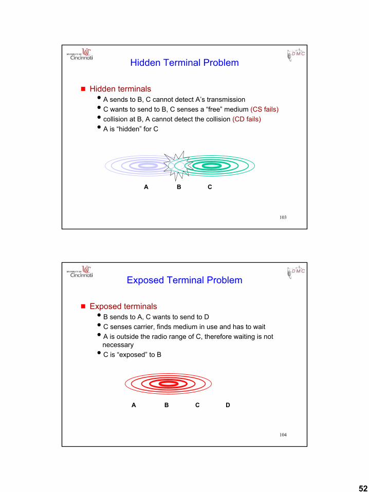
g Hidden terminalsiA sends to B, C cannot detect A’s transmissioniC wants to send to B, C senses a “free” medium (CS fails)icollision at B, A cannot detect the collision (CD fails)iA is “hidden” for C
Hidden Terminal Problem
BA C
104
g Exposed terminalsiB sends to A, C wants to send to DiC senses carrier, finds medium in use and has to waitiA is outside the radio range of C, therefore waiting is not
necessaryiC is “exposed” to B
Exposed Terminal Problem
BA C D
53
105
Multiple Access with Collision Avoidance (MACA) [Karn90]
g MACA uses signaling packets for collision avoidanceiRTS (request to send)
• sender request the right to send from a receiver with a short RTS packet before it sends a data packet
iCTS (clear to send)• receiver grants the right to send as soon as it is ready to
receive
g Signaling packets containisender addressireceiver addressiDuration
g Variants of this method are used in IEEE 802.11
106
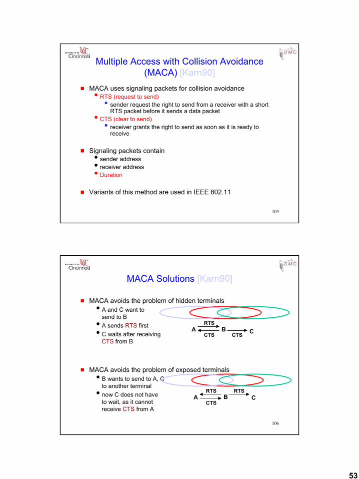
g MACA avoids the problem of hidden terminalsiA and C want to
send to BiA sends RTS firstiC waits after receiving
CTS from B
g MACA avoids the problem of exposed terminalsiB wants to send to A, C
to another terminalinow C does not have
to wait, as it cannot receive CTS from A
MACA Solutions [Karn90]
A B CRTS
CTSCTS
A B CRTS
CTS
RTS
54
107
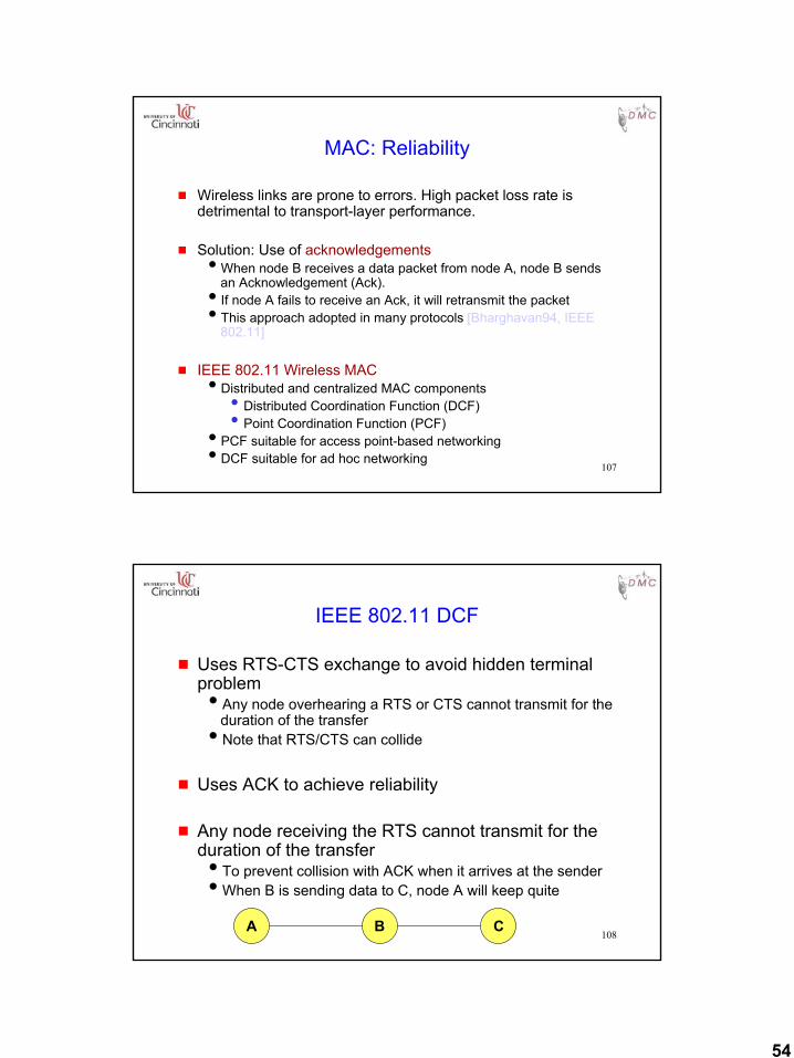
MAC: Reliability
g Wireless links are prone to errors. High packet loss rate is detrimental to transport-layer performance.
g Solution: Use of acknowledgementsiWhen node B receives a data packet from node A, node B sends
an Acknowledgement (Ack). iIf node A fails to receive an Ack, it will retransmit the packetiThis approach adopted in many protocols [Bharghavan94, IEEE
802.11]
g IEEE 802.11 Wireless MACiDistributed and centralized MAC components
• Distributed Coordination Function (DCF)• Point Coordination Function (PCF)
iPCF suitable for access point-based networkingiDCF suitable for ad hoc networking
108
IEEE 802.11 DCF
g Uses RTS-CTS exchange to avoid hidden terminal problemiAny node overhearing a RTS or CTS cannot transmit for the
duration of the transferiNote that RTS/CTS can collide
g Uses ACK to achieve reliability
g Any node receiving the RTS cannot transmit for the duration of the transferiTo prevent collision with ACK when it arrives at the senderiWhen B is sending data to C, node A will keep quite
A B C
55
109
MAC: Collision Avoidance
g With half-duplex radios, collision detection is not possibleg Collision avoidance: Once channel becomes idle, the node waits
for a randomly chosen duration before attempting to transmit
g IEEE 802.11 DCFiWhen transmitting a packet, choose a backoff interval in the range
[0,cw]; cw is contention windowiCount down the backoff interval when medium is idleiCount-down is suspended if medium becomes busyiWhen backoff interval reaches 0, transmit RTS
g Time spent counting down backoff intervals is a part of MAC overhead
g large cw leads to larger backoff intervalsg small cw leads to larger number of collisions
110
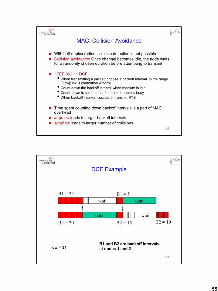
DCF Example
data
waitB1 = 5
B2 = 15
B1 = 25
B2 = 20
data
wait
B1 and B2 are backoff intervalsat nodes 1 and 2cw = 31
B2 = 10
56
111
MAC Protocols: Issues
g Hidden and Exposed Terminal Problemsg Reliabilityg Collision avoidanceg Congestion controlg Energy efficiency
112
MAC: Congestion Control
g IEEE 802.11 DCF: Congestion control achieved by dynamically choosing the contention window cw
g Binary Exponential Backoff in DCF:iWhen a node fails to receive CTS in response to its RTS, it
increases the contention window• cw is doubled (up to an upper bound)
iWhen a node successfully completes a data transfer, it restores cw to CWmin
57
113
MAC: Energy Conservation
g Proposals typically suggest turning the radio off when not needed
g Power Saving Mode in IEEE 802.11 (Infrastructure Mode)iAn Access Point periodically transmits a beacon indicating
which nodes have packets waiting for themiEach power saving (PS) node wakes up periodically to
receive the beaconiIf a node has a packet waiting, then it sends a PS-Poll
• After waiting for a backoff interval in [0,CWmin]iAccess Point sends the data in response to PS-poll
114
MAC Protocols: Summary
g Wireless medium is prone to hidden and exposed terminal problems
g Protocols are typically based on CSMA/CAg RTS/CTS based signalingg ACKs for reliability
g Contention window is used for congestion controlg IEEE 802.11 wireless LAN standardg Fairness issues are still unclear
58
115
Other MAC Protocols
g Lot of other protocols !
g See past MobiCom, WCNC, MilCom, VTC, etc., conferences
116
Wireless Sensor Networks
59
117
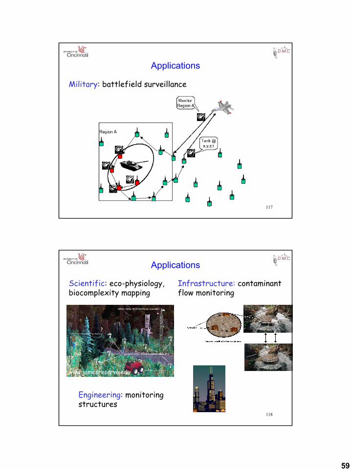
Applications
Military: battlefield surveillance
118
Applications
Scientific: eco-physiology,biocomplexity mapping
Infrastructure: contaminant flow monitoring
Engineering: monitoring structures
www.jamesreserve.edu
60
119
Wireless Sensor Networks
g Why not use proposed Ad Hoc protocols?iThe number of sensor nodes in a sensor network can be several
orders of magnitude higher than the nodes in an ad hoc network.iSensor nodes are densely deployed.iSensor nodes are prone to failures.iSensor nodes mainly use broadcast communication paradigm
whereas most ad hoc networks are based on point-to-point communications.iSensor nodes are limited in power, computational capacities, and
memory.iSensor nodes may not have global identication (ID) because of the
large amount of overhead and large number of sensors.iData-Centric
120
Wireless Sensor Networks
g Characteristics of sensor networks
iApplication Specific Requirements
iData-Aggregation
i“Data-Centric” Property
iLocation Awareness
61
121
A Sensor Node
g May need to fit into a matchbox-sized moduleg Smart dust motei4 MHz Atmel AVR 8535 micro-controlleri8 KB instruction flash memoryi512 bytes RAMi512 bytes EEPROMiTinyOS – 3500 bytes of code
g Each sensor node are assumed to be equipped with a GPS unitiOr a limited number of nodes have GPS and help others to
figure out their locations
122
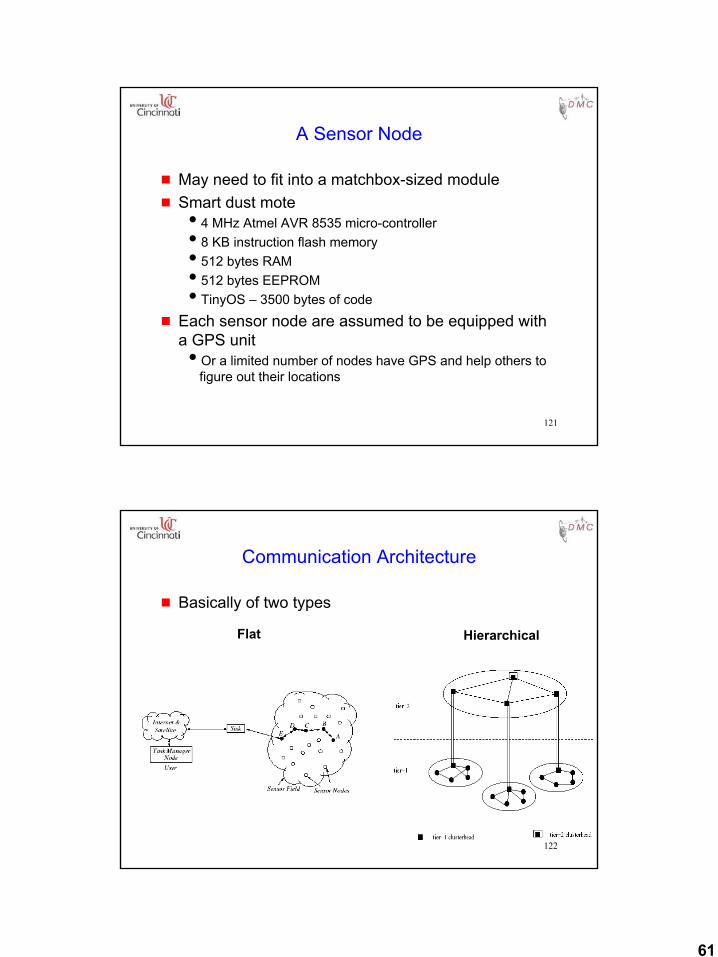
Communication Architecture
g Basically of two types
Flat Hierarchical
62
123
Routing in Sensor Networks
124
Classification of Sensor Networks
g Proactive NetworksiThe nodes in the network periodically switch on their
sensors and transmitters, sense the environment and transmit the data of interest.
g Reactive NetworksiIn this scheme the nodes react immediately to sudden and
drastic changes in the value of sensed attribute.
g Hybrid Networks
63
125
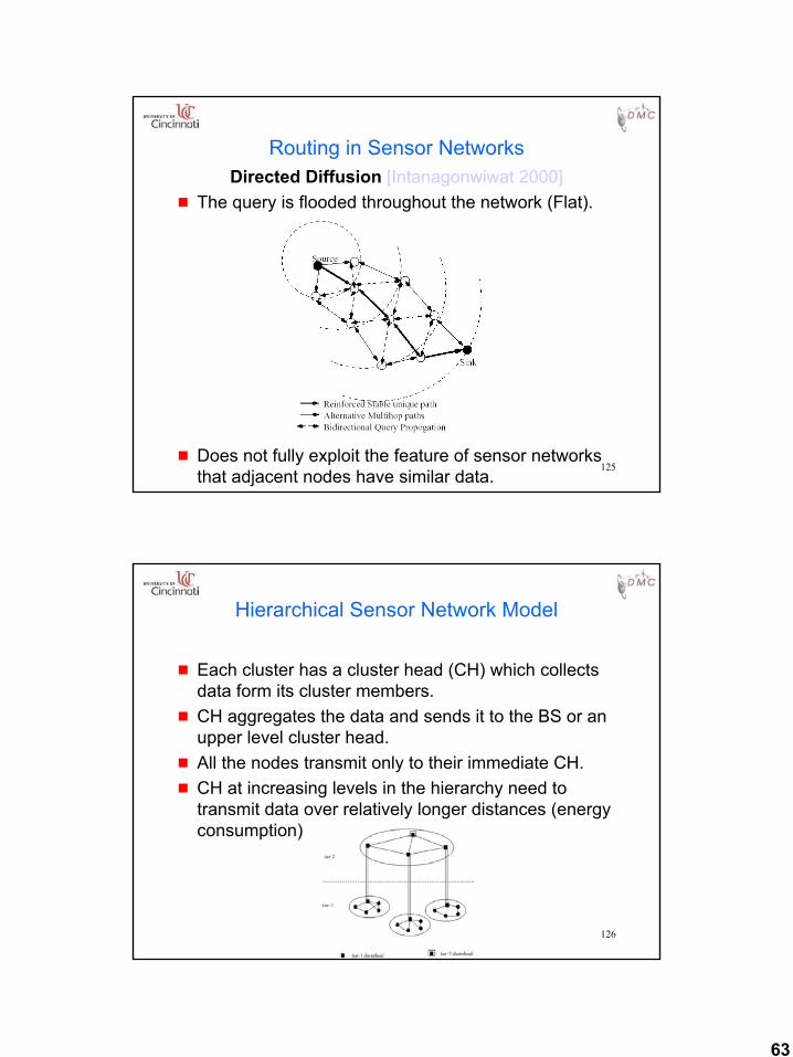
Routing in Sensor NetworksDirected Diffusion [Intanagonwiwat 2000]
g The query is flooded throughout the network (Flat).
g Does not fully exploit the feature of sensor networks that adjacent nodes have similar data.
126
Hierarchical Sensor Network Model
g Each cluster has a cluster head (CH) which collects data form its cluster members.
g CH aggregates the data and sends it to the BS or an upper level cluster head.
g All the nodes transmit only to their immediate CH.g CH at increasing levels in the hierarchy need to
transmit data over relatively longer distances (energy consumption)
64
127
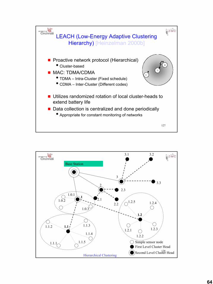
LEACH (Low-Energy Adaptive Clustering Hierarchy) [Heinzelman 2000b]
g Proactive network protocol (Hierarchical)iCluster-based
g MAC: TDMA/CDMAiTDMA – Intra-Cluster (Fixed schedule)iCDMA – Inter-Cluster (Different codes)
g Utilizes randomized rotation of local cluster-heads to extend battery life
g Data collection is centralized and done periodicallyiAppropriate for constant monitoring of networks
128
Base Station
3
3.1 3.2
3.32
2.12.2
2.3
11.0.1
1.0.2
1.0.3
1.2
1.2.5 1.2.4
1.2.3
1.2.2
1.2.11.1 1.1.3
1.1.4
1.1.51.1.1
1.1.2
Hierarchical Clustering
Simple sensor nodeFirst Level Cluster Head
Second Level Cluster Head
65
129
Reactive Network Protocol:TEEN
TEEN (Threshold sensitive Energy Efficient sensor Network protocol) [Manjeshwar 2001]
g Designed for reactive networks.iNodes sense their environment continuously
g In this scheme at every cluster change time, the CH broadcasts the following to its members:iHard Threshold (HT): This is a threshold value for the sensed
attribute.iSoft Threshold (ST): This is a small change in the value of
the sensed attribute which triggers the node to switch on its transmitter and transmit.
130
TEEN
g AdvantagesiSuited for time critical sensing applications.iMessage transmission consumes more energy than data
sensing. So the energy consumption in this scheme is less than the proactive networks.iThe soft threshold can be varied.iAt every cluster change time, the parameters are broadcast
afresh and so, the user can change them as required.
g DisadvantageiIf the thresholds are not reached, the nodes will never
communicate.
66
131
Hybrid Networks
g Combining the best features of proactive and reactive networks while minimizing their limitations to create a new type of network is called a Hybrid Network
132
APTEEN (Adaptive TEEN) [Manjeshwar 2002]
Functioning:
g The cluster heads broadcasts the following parameters to sensors:iAttributes (A): This is a set of physical parameters which the
user is interested in obtaining data about.iThresholds: This parameter consists of a hard threshold (HT)
and a soft threshold (ST).iSchedule: This is a TDMA schedule, assigning a slot to each
node.iCount Time (CT): It is the maximum time period between two
successive reports sent by a node.
67
133
APTEEN
g Proceeds exactly like TEEN plusiIf a node does not send data for a time period equal to the count
time (CT), it is forced to sense and retransmit the data.
g TDMA schedule is used and each node in the cluster is assigned a transmission slot.
134
APTEEN
g AdvantagesiIt combines both proactive and reactive policies.iIt offers a lot of flexibility by allowing the user to set the time
interval (CT) and the threshold values for the attributes.iEnergy consumption can be controlled by changing the count
time as well as the threshold values.
g DisadvantagesiThe main drawback of the scheme is the additional
complexity required to implement the threshold functions and the count time.iRate of energy consumption is increased

68
135
Wireless Sensor NetworksHierarchical X Flat
Fairness not guaranteedFair channel allocation
Energy dissipation adapts to traffic patternEnergy dissipation cannot be controlled
Energy dissipation depends on traffic patternsEnergy dissipation is uniform
Latency in waking up intermediate nodes and setting up the multi-hop path
Lower latency as multi-hop network formed by cluster-heads is always available
Routes formed only in regions that have data for transmission
Overhead of cluster formation throughout the network
Links formed in the fly, without synchronizationRequires global and local synchronization
Routing is complex but optimalSimple but non-optimal routing
Node on multi-hop path aggregates incoming data from neighbors
Data aggregation by cluster head
Variable duty cycle by controlling sleep time of nodes
Reduced duty cycle due to periodic sleeping
Collision overhead presentCollisions avoided
Contention-based schedulingReservation-based scheduling
FlatHierarchical
136
Current Research Projects
69
137
Related Standards Activities
138
Internet Engineering Task Force (IETF)Activities
g IETF manet (Mobile Ad-hoc Networks) working groupihttp://www.ietf.org/html.charters/manet-charter.html
g IETF mobileip (IP Routing for Wireless/Mobile Hosts) working groupihttp://www.ietf.org/html.charters/mobileip-charter.html
70
139
Related Standards Activities
g BlueToothihttp://www.bluetooth.com
g IEEE 802.15ihttp://grouper.ieee.org/groups/802/15/
g HomeRF [Lansford00ieee]ihttp://www.homerf.org
g IEEE 802.11ihttp://grouper.ieee.org/groups/802/11/
g HiperLan/2ihttp://www.etsi.org/technicalactiv/hiperlan2.htm
140
Bluetooth[Haartsen98]
g Features: Cheaper, smaller, low power, ubiquitous, unlicensed frequency band (2.4GHz)
g Current Spec version 1.1 (1600+ pages)
g Promoter group consisting of 9 iEricsson, IBM, Intel, Nokia, Toshiba, 3Com, Agere,
Microsoft, Motorola
g 3000+ adopters
71
141
Bluetooth: Link Types
g Designed to support multimedia applications that mix voice and data
g Synchronous Connection-Oriented (SCO) linkiSymmetrical, circuit-switched, point-to-point connectionsiSuitable for voiceiTwo consecutive slots (forward and return slots) reserved at
fixed intervals
g Asynchronous Connectionless (ACL) linkiSymmetrical or asymmetric, packet-switched, point-to-
multipointiSuitable for bursty dataiMaster units use a polling scheme to control ACL
connections
142
Bluetooth: Piconet
g A channel is characterized by a frequency-hopping pattern
g Two or more terminals sharing a channel form a piconetiRoughly 1 Mbps per Piconet
g One terminal in a piconet acts as a master and up to 7 slaves
g Other terminals are slavesg Polling scheme: A slave may send in a slave-to-
master slot when it has been addressed by its MAC address in the previous master-to-slave slot
72
143
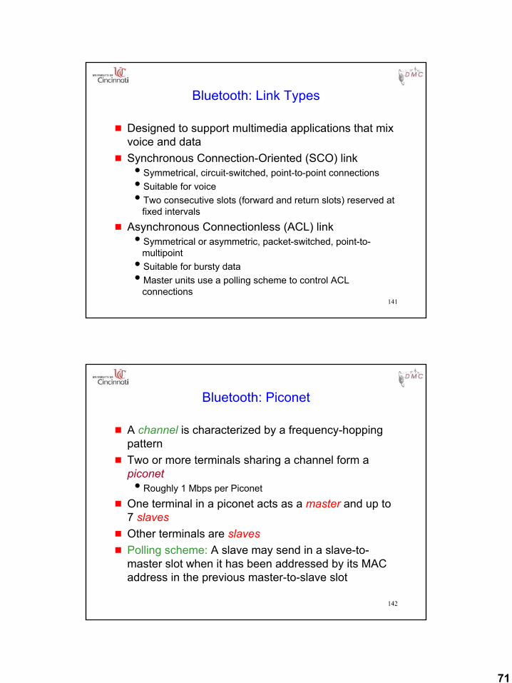
Bluetooth: Scatternet
g Several piconets may exist in the same area (such that units in different piconets are in each other’s range)iA large number of piconets in the vicinity may eventually
interfere with each other [Cordeiro01Globecom]iInterference mitigation schemes [Cordeiro02Sbrc]
g A group of piconets is called a scatternetiNew routing issues [Bhagwat99Momuc]
144
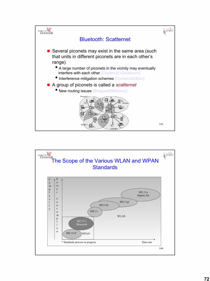
The Scope of the Various WLAN and WPAN Standards
* Standards process in progress Data rate
WPAN
WLAN
Complexity
Power
Consumption
802.11
802.11b802.11g*
802.11aHiperLAN
802.15.1Bluetooth
802.15.4*
73
145
Open Issuesin
Mobile Ad Hoc Networking
146
Open Problems
g Issues other than routing have received much less attention so far
Other interesting problems:
g Address configuration (DHCP ???)g MAC protocolsg Improving interaction between protocol layersg QoS issuesg Applications for MANET

74
147
Thank you !!!
For more information, send e-mail toCarlos Cordeiro at
[email protected] visit
http://www.ececs.uc.edu/~cordeicm