mmuullttiillooaadd iiii ccoommmmuunniiccaattiioonnss ...€¦ · mmuullttiillooaadd iiii...
TRANSCRIPT

MMuullttiiLLooaadd IIII
CCoommmmuunniiccaattiioonnss GGuuiiddee IInncclluuddiinngg::
MMuullttiiLLooaadd IIII
MMuullttiiLLooaadd IIII SSMMPP
MMuullttiiLLooaadd IIII MMoobbiillee
Part # 6077
Firmware Version 3/4.31.11
June2013

2
Copyright Notice
Copyright © 2000 – 2013 Toptech Systems, Inc. The information contained in this document is proprietary and confidential. No part of this document may be copied, reproduced, or transmitted in any medium without the express written permission of Toptech Systems, Inc.
Disclaimer
Toptech Systems assumes no responsibility for damages resulting from installation or use of its products. Toptech Systems will not be liable for any claims of damage, lost data, or lost time as a result of using its products.
Toptech
Systems, Inc.
logo is a registered trademark of Toptech Systems, Inc.
TMS™, TMS5™, TMS6™, RCU II Remote Control Unit™, Toptech MultiLoad II™, MultiLoad II –RCU™, MultiLoad II –1-Arm™, MultiLoad II – SMP™, FCM Flow Control Module™ are trademarks of Toptech Systems, Inc.
Copyright © 2000 – 2013 Toptech Systems, Inc. All Rights Reserved.

3
Table of Contents CHAPTER 1 PROTOCOL SPECIFICATION ..................................................................................................... 6
1.1 DEFINITIONS ............................................................................................................................................ 6
1.2 SMITH PROTOCOL .................................................................................................................................... 7
1.3 BROOKS PROTOCOL ................................................................................................................................. 7
1.4 DANIELS PROTOCOL ................................................................................................................................. 7
1.5 MODBUS-RTU PROTOCOL ........................................................................................................................ 8
1.5.1 Read Holding Registers (fn=3) .......................................................................................................... 8
1.5.2 Write Single Registers (fn=6)............................................................................................................. 8
1.5.3 Loopback/Maintenance (fn=8) ........................................................................................................... 9
1.5.4 Preset Multiple Registers (fn=16) ...................................................................................................... 9
1.5.5 Error Responses (fn= +128) .............................................................................................................. 9
1.5.6 Modbus Register Map Summary ..................................................................................................... 10
1.5.7 Extended Services Register ............................................................................................................ 10
CHAPTER 2 MULTILOAD COMMAND RESPONSES ................................................................................... 11
CHAPTER 3 QUERY COMMAND: .................................................................................................................. 13
CHAPTER 4 FUNCTION COMMANDS: .......................................................................................................... 14
CHAPTER 5 TERMINAL COMMANDS: .......................................................................................................... 16
5.1 TERMINAL ESCAPE COMMANDS:.............................................................................................................. 16
CHAPTER 6 METER COMMANDS: ................................................................................................................ 21
6.1 AUTHORIZE PRESET (PRODUCT AND PRESET VOLUME): ........................................................................... 21
6.2 CLEAR ALARMS: ..................................................................................................................................... 21
6.3 ENABLE PRESET .................................................................................................................................... 21
6.4 END TRANSACTION ................................................................................................................................. 21
6.5 BATCH COMPLETE .................................................................................................................................. 22
6.6 BATCH END:........................................................................................................................................... 22
6.7 END BATCH:........................................................................................................................................... 22
6.8 PRESET MESSAGE: ................................................................................................................................ 23
6.9 PROVING TRANSACTION MODE: .............................................................................................................. 23
6.10 REQUEST STATUS & PRESET ALARMS: .................................................................................................... 24
6.11 REQUEST SMP STATUS & PRESET ALARMS: ........................................................................................... 48
6.12 TRIP PRESET ALARMS: ........................................................................................................................... 48
6.13 REQUEST BAY ALARMS: ......................................................................................................................... 49
6.14 REQUEST COMPONENT ALARMS: ............................................................................................................ 50
6.15 REQUEST METER ALARMS: ..................................................................................................................... 51
6.16 REQUEST ADDITIVE ALARMS: .................................................................................................................. 52
6.17 REMOTETRANSACTIONDATA: .................................................................................................................. 53
6.18 START PRESET FLOW: ............................................................................................................................ 54
6.19 STOP PRESET FLOW: ............................................................................................................................. 54
CHAPTER 7 REGISTER OPERATIONS: ........................................................................................................ 55
7.1 GENERIC REGISTERS ............................................................................................................................. 56

4
7.1.1 Register Data Types ........................................................................................................................ 56
7.1.2 000 – RCU Level Configuration Registers ...................................................................................... 64
7.1.3 100 – Bay Level Configuration Registers ........................................................................................ 66
7.1.4 101 – Preset Level Configuration Registers .................................................................................... 67
7.1.5 102 – Meter Level Configuration Registers ..................................................................................... 70
7.1.6 103 – Component Level Configuration Registers ............................................................................ 74
7.1.7 104 – Additive Level Configuration Registers ................................................................................. 76
7.1.8 105 – Custom Logic Definitions Registers ...................................................................................... 78
7.1.9 200 – Stand Alone BOL Definition Registers .................................................................................. 86
7.1.10 800 – Transaction Archive Registers .......................................................................................... 89
7.2 SPECIAL PURPOSE REGISTERS ............................................................................................................... 91
7.2.1 000 – MultiLoad Firmware Version .................................................................................................. 91
7.2.2 001 – Date and Time ....................................................................................................................... 92
7.2.3 003 – FCM Poll Rate ....................................................................................................................... 92
7.2.4 005 – Current BOL/Ticket Number .................................................................................................. 92
7.2.5 070 – Ethernet Enable ..................................................................................................................... 92
7.2.6 071 – IP Address ............................................................................................................................. 93
7.2.7 072 – IP Mask .................................................................................................................................. 93
7.2.8 073 – IP Gateway ............................................................................................................................ 93
7.2.9 074 – IP Host ................................................................................................................................... 93
7.2.10 076 – ADMIN PASSWORD ......................................................................................................... 93
7.2.11 077 – USER PASSWORD .......................................................................................................... 93
7.2.12 085 – Modem Initialization String ................................................................................................ 93
7.2.13 091..093 – Communication Port Parameters .............................................................................. 94
7.2.14 095..099 – Program Mode Passwords (5) .................................................................................. 95
7.2.15 112 - Real-Time Preset Total Gross Totalizers ........................................................................... 95
7.2.16 113 - Real-Time Preset Total Net Totalizers ............................................................................... 95
7.2.17 114 - Real-Time Preset Total Mass Totalizers ............................................................................ 96
7.2.18 133 – FCM IO Access ................................................................................................................. 96
7.2.19 140 –Current Latitude/Longitude position Registers (MultiLoad Mobile Only) ........................... 97
7.2.20 141 – Current Transaction Latitude/Longitude/Site Index Registers (MultiLoad Mobile Only) ... 97
7.2.21 400 - Preset Definition Registers ................................................................................................ 98
7.2.22 401 – External Preset Display Register ...................................................................................... 98
7.2.23 500 - Product Definition Registers .............................................................................................. 98
7.2.24 600 - Standalone Driver Card Database ..................................................................................... 99
7.2.25 650 –GPS Site Database (MultiLoad Mobile Only) ................................................................... 100
7.2.26 700 - Configurable Language Prompts ..................................................................................... 100
7.2.27 710 - Bay Alarm Messages ....................................................................................................... 101
7.2.28 711 - Preset Alarm Messages ................................................................................................... 103
7.2.29 712 - Meter Alarm Messages .................................................................................................... 104
7.2.30 713 - Component Alarm Messages ........................................................................................... 106
7.2.31 714 - Additive Alarm Messages ................................................................................................ 108
7.2.32 910 – Read Event Log Message Queue ................................................................................... 110
7.2.33 912 – Read W & M Change Log Message Queue .................................................................... 110
7.2.34 950 - Current Driver Card Number ............................................................................................ 110
7.2.35 951..955 - Current Driver Prompt Information ........................................................................... 111

5
7.2.36 960 – Input Data ........................................................................................................................ 111
7.2.37 961 – Input Data Terminating Key ............................................................................................ 111
7.2.38 962 - Current Driver Card Data ................................................................................................. 111
7.2.39 998 – Bitmap Graphic Cache .................................................................................................... 113
CHAPTER 8 COMMUNICATION TRACE EXAMPLE ................................................................................... 114
8.1 STARTUP OF HOST SOFTWARE ............................................................................................................. 114
8.1.1 Update Date & Time ...................................................................................................................... 114
8.1.2 Update Product Definitions ............................................................................................................ 114
8.1.3 Update Preset Definitions .............................................................................................................. 115
8.1.4 Status Query .................................................................................................................................. 115
8.2 TRANSACTION AUTHORIZATION ............................................................................................................. 116
8.2.1 Process Driver Card In .................................................................................................................. 116
8.2.2 Authorize a Transaction on MultiLoad ........................................................................................... 117
8.2.3 Reading Totalizers ......................................................................................................................... 117
8.3 BATCH AUTHORIZATION ........................................................................................................................ 118
8.3.1 Authorize a Batch on MultiLoad ..................................................................................................... 118
8.3.2 Monitor Load During Delivery ........................................................................................................ 120
8.4 END OF BATCH PROCESSING ................................................................................................................ 120
8.4.1 Ending a Batch on MultiLoad ......................................................................................................... 120
8.5 END OF TRANSACTION PROCESSING ..................................................................................................... 121
8.5.1 Ending a Transaction on MultiLoad ............................................................................................... 121
8.6 SHUTDOWN OF HOST SOFTWARE .......................................................................................................... 121
CHAPTER 9 DATA COMMUNICATION NOTES AND RECOMMENDATIONS ........................................... 122
9.1 PROTOCOL SELECTION: RS-232 VS. RS-485 ........................................................................................ 122
9.1.1 RS-232 ........................................................................................................................................... 122
9.1.2 RS-485 ........................................................................................................................................... 122
9.2 CABLE SELECTION................................................................................................................................ 122
9.3 LINE TERMINATION IN MULTI-DROPPED COMMUNICATIONS ..................................................................... 122
9.4 OPTICAL ISOLATION .............................................................................................................................. 123
9.5 SHIELD GROUNDING ............................................................................................................................. 123

Chapter 1 – Protocol Specification 6
CHAPTER 1 PROTOCOL SPECIFICATION
The MultiLoad auto-detects four low level computer protocols for host communications.
- Smith Protocol
- Brooks Protocol
- Daniels
- Modbus-RTU Protocol
Note: All unknown or not allowed signal or code sequences are rejected and have no impact on the software or measurement data.
Host communication can occur via multi-dropped RS-232/RS-485 serial on COM 1 or Ethernet 10/100 socket communication on port 7734.
1.1 DEFINITIONS
The non-printing characters that form the skeleton of the Smith and Brooks protocols are standard ASCII (American Standard Code Information Interchange):
ASCII CHARACTER DECIMAL HEX BINARY
NUL 0 0 00000000
STX 2 2 00000010
ETX 3 3 00000011
SOH 1 1 00000001
PAD 127 7F 01111111
CHARACTER DESCRIPTION
BCC Block Check Characters. The ASCII hex representation of the binary sum of all the data in the message from the SOH through the ETX character.
LRC Longitudinal Redundancy Check. The LRC is an ASCII character computed as the exclusive or (XOR) sum of all characters following the STX and including the ETX.
CRC Cyclic Redundancy Check.
A1..A3 A 3-character ASCII unit address of the MultiLoad. Please refer to the MultiLoad User Guide for configuring the unit address.
D1..Dn Data field characters.
Fn Function field code.
Adr A single character binary unit address of the MultiLoad.

Chapter 1 – Protocol Specification 7
1.2 SMITH PROTOCOL
The Smith protocol is compatible with devices from Smith Meter, such as the Accuload I and Accuload II mini- computer modes of operation. Using this protocol, MultiLoad accepts data in the format:
NUL STX A1 A2 data ETX LRC PAD
A1 and A2 are the last two digits of the unit address in the RCU configuration.
1.3 BROOKS PROTOCOL
The Brooks protocol is compatible with devices from Brooks Instruments such as their Petrocount RAU™ and IMS Control™ units running in computer mode. Using this protocol, MultiLoad accepts data in the format:
SOHDESTINATION SOURCE
A1 A2 A3 S1 S2 S3
STX data ETXBCC
1
BCC
2
1.4 DANIELS PROTOCOL
The Daniels protocol is compatible with devices from Daniels Flow Products. Using this protocol, MultiLoad accepts and responds with data in the format:
Quiet Time
ADR FN LEN
(2 – 252) D1...DN CRC1 CRC2
Quiet Time
Daniels protocol messages are framed by a quiet time of three and one-half characters.
ADR is binary character of the address of the MultiLoad. Typically 0x01.
Fn is expected to be 0x41/0x42 alternating on each command. Responses will have Fn as 0x41/0x42 for normal responses and 0xc1/0xc2 for exception responses.
D1…Dn is string data containing the commands listed in this manual.
Note: Modbus extension to return larger packet sizes: On messages with data packet sizes from 2 to 252 characters the Fn values of 0x41/0x42 will be returned. With messages outside this range, Fn will be the MSB value of the data size and the Len will be LSB of the data size.
For Example:
Fn = 0x41, Len = 0x80, when data packet size = 0x0080,
Fn = 0x42, Len = 0x80, when data packet size = 0x0080,
Fn = 0x00, Len = 0xFF, when data packet size = 0x00FF ( 255),
Fn = 0x01, Len = 0x00, when data packet size = 0x0100 ( 256),
Fn = 0x01, Len = 0x01, when data packet size = 0x0101 ( 257),
Fn = 0x02, Len = 0x00, when data packet size = 0x0200 ( 512),
Fn = 0x04, Len = 0x00, when data packet size = 0x0400 (1024),
Fn = 0x08, Len = 0x00, when data packet size = 0x0800 (2048).

Chapter 1 – Protocol Specification 8
1.5 MODBUS-RTU PROTOCOL
The Modbus-RTU protocol has been implemented to be as compatible as possible with the original published Modicon Modbus-RTU standard.
Note: The Modbus protocol allows parameter register access only as defined by the explicit mapping in this manual. To send the ASCII commands (R000, T`A, MAM, MRS, etc.) that are handled by the other three protocols, the Modbus Extended Services registers must be used.
Using the modbus protocol, MultiLoad accepts data in the following format:
Quiet Time
ADR FN ... CRC1 CRC2 Quiet Time
Modbus-RTU protocol messages are framed by a quiet time of three and one-half characters.
ADR is binary character of the address of the MultiLoad. Typically 0x01.
Fn is the Modbus function. Functions implemented are as follows.
The formal specification of Modbus lists the starting Holding Register address as 40001. The Modbus Holding Register functions (Fn 3, 6 and 16) all have an implied 4XXXX reference. Referencing Holding Register 40001 is addressed as register 0000 in the register address field in the message for fn 3, 6, and 16.
Since Modbus addressing has been implemented in various ways over the years, to avoid confusion in this manual, the Modbus Holding Register addresses listed are the value in the register address field in the message. If it is necessary to know the formal Modbus Holding Register address, simply add 40001 to the register addresses listed in the manual.
1.5.1 READ HOLDING REGISTERS (FN=3)
Note: Both Modbus registers MUST be read at the same time when reading 32-bit values.
Tx:
Quiet Time ADR FN=3 Start
Register MSB
Start Register
LSB
Number
Of Registers
MSB
Number of
Registers LSB
CRC1 CRC2 Quiet Time
Rx:
Quiet Time
ADR
FN=3
(+128 if error)
Byte Count
1st
Register
MSB
1st
Register LSB
Next Register
MSB
Next Register
MSB … CRC1 CRC2
Quiet Time
1.5.2 WRITE SINGLE REGISTERS (FN=6)
Note: cannot be used for 32-bit registers.
Tx:
Quiet Time ADR FN=6 Start
Register MSB
Start Register
LSB
Register
MSB
Register
LSB CRC1 CRC2 Quiet Time
Rx:
Quiet Time ADR
FN=6
(+128 if error)
Start Register
MSB
Start Register
LSB
Register
MSB
Register
LSB CRC1 CRC2 Quiet Time

Chapter 1 – Protocol Specification 9
1.5.3 LOOPBACK/MAINTENANCE (FN=8)
Note: only loopback of command supported.
Tx:
Quiet Time ADR FN=8 Diagnostic Code MSB
Diagnostic Code LSB
Data MSB Data LSB CRC1 CRC2 Quiet Time
Rx:
Quiet Time ADR FN=8 Diagnostic Code MSB
Diagnostic Code LSB
Data MSB Data LSB CRC1 CRC2 Quiet Time
1.5.4 PRESET MULTIPLE REGISTERS (FN=16)
Note: Both Modbus registers MUST be written at the same time when writing 32-bit values.
Tx:
Quiet Time
ADR FN=16 Start
Register MSB
Start Register
LSB
Number
Of Registers
MSB
Number of
Registers LSB
Byte Count
1st
Register
MSB
1st
Register LSB
Next Register
MSB
Next Register
MSB … CRC1 CRC2
Quiet Time
Rx:
Quiet Time ADR
FN=16
(+128 if error)
Start Register
MSB
Start Register
LSB
Number
Of Registers
MSB
Number of
Registers LSB
CRC1 CRC2 Quiet Time
1.5.5 ERROR RESPONSES (FN= +128)
Rx:
Quiet Time ADR FN+128 Error
Subcode CRC2 CRC1
Error Sub codes are:
1 = Invalid Function Code. Indicates that the use of an invalid or unimplemented function has been attempted.
2 = Invalid Address Field. Indicates that a read or write was made to an invalid address. Can also indicate that a read or write to a single register of a 32-bit value has been attempted.
3 = Invalid Data Field. Indicates that an attempt to write an invalid value to a register has occured. This error code will also be returned if an attempt is made to change a value under Weights and Measures control without with W&M switch being in the active state.
4 = Query Processing Failure. This code is not returned.

Chapter 1 – Protocol Specification 10
1.5.6 MODBUS REGISTER MAP SUMMARY
1 – 999 General, BOL Template, Misc. Configurations.
1000 – 1199 RCU Configurations
1200 – 1399 Bay Configurations
1400 – 1599 Preset Configurations
1600 – 1799 Meter Configurations
1800 – 1999 Component Configurations
2000 – 2199 Additive Configurations
2200 – 2999 Product, Alarm, Database, Misc. Configurations
3000 – 3999 Totalizers
4000 – 6000 Preset, Meter, Component and Additive Status
7000 – 7799 Status, Authorization Control and Alarms
7800 – 7999 Transaction Archive
8000 – 8999 Preset Definitions
9000-10999 Extended Services Register
1.5.7 EXTENDED SERVICES REGISTER
Not all commands native to the MultiLoad II have corresponding mapping to Modbus registers. The Extended Services register was implemented as a way to support sending and receiving native Multiload II commands across the Modbus RTU interface. Any native command listed can be sent to the MultiLoad via the extended Services Register.
Modbus Registers:
Write Holding Register=9000, Len=1, 16-Bit Integer (Command Length)
Write Holding Register=9001, Max Len=999, Characters (Command Text)
Read Holding Register=9000, Len=2, 32-Bit Integer (Reply Length)
Read Holding Register=9001, Max Len=999, Characters (Reply Text)
Perform the following operations to use of the Extended Services Register:
1. Write the Command Length into the Holding Register 9000 (max value of 999 characters).
2. Write the Command Text into the Holding Register 9001 (max length of 999).
3. Command will execute when the final character of the Command Text is written (9001+Command Length-1).
4. Read the Reply Length from the Holding Register 9000 (max value of 999 characters).
5. Read the Reply Text from the Holding Register 9001 (max length of 999).
Steps 1 & 2 can be done with a single Modbus Function 16.
Steps 4 & 5 can be done with a single Modbus Function 3.

Chapter 2 –MultiLoad Responses 11
CHAPTER 2 MULTILOAD COMMAND RESPONSES
<command_status> <rcu_status> <card_status> <command specific response data>
For MultiLoad to acknowledge a message two conditions must be meet. First the message must fit the Message Framing Protocol with a valid LRC, BCC or CRC. Second, the address specified in the first two characters of the command must match the configured MultiLoad address. Any message that satisfies both of these requirements will be sent a response.
Modbus:
If using the Modbus protocol, the Modbus Extended Services Registers must be used to pass in these ASCII string commands.
The first three characters of every response will contain command, RCU and card status data as defined below.
enum
{
VALID_COMMAND = ‘0’,
INVALID_PARAMETER = ‘1’,
INVALID_COMMAND = ‘2’
} command_status;
enum
{
IDLE = '0',
AUTH_BAY = 4',
MENU_MODE = '9',
DIAG_MODE = '%',
AUTHORIZING_LOAD = 'A',
LOAD_AUTHORIZED = 'B',
COMPLETING_LOAD = 'C',
TRANSACTION_DONE = 'D',
TRANSACTION_CANCEL = 'E',
PULLING_TRANSACTION = 'P',
ARCHIVING_TRANSACTION = 'R',
TRANSACTION_AUTHORIZED = 'T',
RCU_NOT_CONFIGURED = '?',
RCU_POWER_UP = '!',
INITIALIZING = 'I',
NO_TRANSACTION = 'N',
REMOTE_AUTH_PRESET1 = 'a',
REMOTE_AUTH_PRESET2 = 'b',
REMOTE_AUTH_PRESET3 = 'c',
REMOTE_AUTH_PRESET4 = 'd',
REMOTE_AUTH_PRESET5 = 'e',
REMOTE_AUTH_PRESET6 = 'f',
REMOTE_AUTH_PRESET7 = 'g',
REMOTE_AUTH_PRESET8 = 'h',

Chapter 2 –MultiLoad Responses 12
REMOTE_AUTH_PRESET9 = 'i',
REMOTE_AUTH_PRESET10 = 'j',
REMOTE_AUTH_PRESET11 = 'k',
REMOTE_AUTH_PRESET12 = 'l',
REMOTE_AUTH_PRESET13 = 'm',
REMOTE_AUTH_PRESET14 = 'n'
} rcu_status;
Modbus:
Read Only Register=7000, Len=1, Character (rcu_status)
enum
{
CARD_NOT_INSERTED =’0’,
CARD_INSERTED =’1’
} card_status;
Modbus:
Read Only Register=7001, Len=1, Character (card_status)
In most cases a command will return additional information specific to the command. This information will always follow the three status characters. For example if the following valid command to read the current firmware version is sent:
Command => Response
R000 => 0?0000MultiLoad II v3.29.xx Jan xx 2009
With “0?0” as the three status characters and “000MultiLoad II v3.29.xx Jan xx 2009” as the command specific response.

Chapter 3 – Query Command 13
CHAPTER 3 QUERY COMMAND:
Query Command => Response
Q => 0?0XXXX
Where:
XXXX = 4 digit hexadecimal number with bits representing the rcu_status as:
union
{
unsigned int value;
struct
{
unsigned char rcu_trans_header:1;
unsigned char proving_mode:1;
unsigned char power_up:1; // indicated system has been powered on
unsigned char configured:1; // indicates configuration state
unsigned char unassigned_keypress_on_load_screen:1;
unsigned char logmsg_queued:1; // a log message is available
unsigned char unused6:1;
unsigned char unused7:1;
unsigned char wm_logmsg_queued:1; // a w&m log message is available
unsigned char host_up:1; // host system is up, card in will be allowed.
Unsigned char input_in_progress:1;
unsigned char input_done:1;
unsigned char keypad_locked :1; // is keypad locked or not
unsigned char reserved13:1;
unsigned char wm_key:1; // W&M key is active
unsigned char program_key:1; // Program key is active
} flags;
} rcu_status;
This command also resets the Host Down Timer and should be issued periodically to notify MultiLoad that the Host is still active.
Modbus:
Read Only Register=7002, Len=1, 16-Bit Integer (XXXX)

Chapter 4 – Function Commands 14
CHAPTER 4 FUNCTION COMMANDS:
FREBOOT = Performs a software reboot of the MultiLoad RCU.
FFACTORY = Restores all MultiLoad registers to factory defaults.
FUPDATEAPPFLASH = Updates the Flash with an uploaded image (req. W&M and a valid image)
Modbus:
Supported through Modbus Extended Services Registers.
FKEYPADON = Enables the keypad on the MultiLoad RCU (default it is active)
FKEYPADOFF = Disables the keypad on the MultiLoad RCU
Write Only Register=7008, Len=1, 16-Bit Integer (any value=FKEYPADON)
Write Only Register=7009, Len=1, 16-Bit Integer (any value=FKEYPADOFF)
FUNCONFIG = Clears the configured RCU status bit.
FRECONFIG = Sets the configured RCU status bit.
Modbus:
Write Only Register=7010, Len=1, 16-Bit Integer (any value=FUNCONFIG)
Write Only Register=7011, Len=1, 16-Bit Integer (any value=FRECONFIG)
FPOWERUP = Resets the power_up RCU status bit. This bit is set on power up.
Modbus:
Write Only Register=7012, Len=1, 16-Bit Integer (any value=FPOWERUP)
FHOSTUP = Sets the host_up RCU status bit. Cleared on power up or when host down timeout expires between Q commands. Command should be issued when host system starts communicating with MultiLoad.
Modbus:
Write Only Register=7013, Len=1, 16-Bit Integer (any value=FHOSTUP)
FHOSTDOWN = Clears the host_up RCU status bit. Command should be issued when host system stops communicating with MultiLoad.
Modbus:
Write Only Register=7014, Len=1, 16-Bit Integer (any value=FHOSTDOWN)
FHOSTWAIT = Bypass host down timer once with alternate timeout.
Modbus:
Write Only Register=7015, Len=1, 16-Bit Integer (any value=FHOSTUP)
FEODLOG = Prints EOD-Report for all totalizers type by arm and also gives the thruput between the feodlog commands
Modbus:
Write Only Register=7018, Len=1, 16-Bit Integer (any value=FEODLOG)

Chapter 4 – Function Commands 15
FPccc…. = Send ccc… characters to the attached printer port (if defined).
FCLEARPROD = Clear all product definitions (500 register) except for the 000-Unknown Product definition.
FCLEARID = Clear Access ID and PIN database.
FCLEARCUSTOM = Clears all custom logic entries.
Modbus:
Supported through Modbus Extended Services Registers.

Chapter 5 – Terminal Commands 16
CHAPTER 5 TERMINAL COMMANDS:
Ts…
Where:
s… = Any text string to display. Display string may contain one or more terminal escape commands.
5.1 TERMINAL ESCAPE COMMANDS:
<ESC><Terminal Escape Command and parameters >
Where Terminal Escape Commands are:
A Authorize Transaction:
Authorize MultiLoad Transaction. Will display load screen.
Modbus:
Write Only Register=7016, Len=1, 16-Bit Integer (any value=Authorize Transaction)
Cx Clear RCU counters
Where,
X = counter to clear, 1 = counter 1, 2 = counter 2
E Setup Data Entry
Used to display a flashing cursor (Setup Data Entry Length > 1) and allow user input. Data to be retrieved at R960, R961.
F Turn on Big Font
Used to enable double size font.
F Turn off Big Font
Used to return to normal size font.
G Set Foreground/Background Text Colors
Where:
f = (character) 0x20 + Foreground Color Palette Index
b = (character) 0x20 + Background Color Palette Index
Pixel color palette index values defined as:
Black = 0x00
Blue = 0x01
Red = 0x02
Magenta = 0x03
Green = 0x04
Cyan = 0x05
Yellow = 0x06
White = 0x07
Custom 0 = 0x08 (Not available)

Chapter 5 – Terminal Commands 17
Custom 1 = 0x09 (Not available)
Custom 2 = 0x0a (Not available)
Custom 3 = 0x0b (Not available)
Custom 4 = 0x0c (Not available)
Custom 5 = 0x0d (Not available)
Flash 1 = 0x0e
Flash 2 = 0x0f
Example: To display a green word „Hello‟ code the string as follows:
T<ESC>G$‟Hello
$ = 0x20 + 0x04 (Green) „ = 0x20 + 0x07 (White)
H Home Cursor to Position (0,0)
Move cursor position to upper left corner of screen.
Ircle Set Reverse Video
Where:
r = (character) 0x20 + Top Text Row Position (0 = top, 15 = bottom)
c = (character) 0x20 + Left Text Column Position (0 = left, 39 = right)
l = (character) 0x20 + Length in Text Columns
e = “0” or “1” (0 = Set Inverse Text, 1 = Clear Inverse Text)
J Erase from Cursor to End of Line
Use with after <ESC>Y first to clear an entire line. Can be used as a CR since cursor will be positioned on next line.
K Erase from Cursor to End of Screen
Use with after <ESC>H to clear entire screen.
Lxx Setup Data Entry Length
Where:
xx = Length of Data Entry Input Required (00-25) (0 = Key Press with No Flashing Cursor)
N Turn On Cursor
O Turn Off Cursor
R Reset the RCU Display
Modbus:
Write Only Register=7017, Len=1, 16-Bit Integer (any value=Reset RCU Display)
Yrc Set Cursor Position
Where:
r = (character) 0x20 + Top Text Row Position (0 = top, 15 = bottom)
c = (character) 0x20 + Left Text Column Position (0 = left, 39 = right)
X Clear Entire Display

Chapter 5 – Terminal Commands 18
< Unlock the Display
> Lock the Display
@ Turn Character Echo On
! Turn Asterisk Echo On
arcwh Draw Progress Box
Where:
r = (character) 0x20 + Top Text Row Position (0 = top, 15 = bottom)
c = (character) 0x20 + Left Text Column Position (0 = left, 39 = right)
w = (character) 0x20 + Width in Text Columns
h = (character) 0x20 + Height in Text Rows Down
brcwhp Update Progress Box
Where:
r = (character) 0x20 + Top Text Row Position (0 = top, 15 = bottom)
c = (character) 0x20 + Left Text Column Position (0 = left, 39 = right)
w = (character) 0x20 + Width in Text Columns
h = (character) 0x20 + Height in Text Rows Down
p = (character) 0x20 + Percent Value to Display (0 = None, 100 = Full)
crcpf Display Animation Frame
Where:
r = (character) 0x20 + Top Text Row Position (0 = top, 15 = bottom)
c = (character) 0x20 + Left Text Column Position (0 = left, 39 = right)
p = (character) 0x20 + Animation Picture Index
f = (character) 0x20 + Animation Frame Index
Note: Test only since Animation Picture Index and Animation Frame Index values may change between firmware versions.
Df Display Factory Logo
Where:
f = (character) 0x20 + Factory Logo Index
Note: Test only since Factory Logo Index values may change between firmware versions.
Ercwd… Draw Display Graphic
Where:
r = (character) 0x20 + Top Text Row Position (0 = top, 15 = bottom)
c = (character) 0x20 + Left Text Column Position (0 = left, 39 = right)
w = (character) 0x20 + Width in Text Columns
d = (character) 0x20 + pixel color palette index values from left to right, top to bottom,
Note: Each text column = 16 pixels wide, each text row = 30 pixels high
Pixel color palette index values defined as:

Chapter 5 – Terminal Commands 19
Black = 0x00
Blue = 0x01
Red = 0x02
Magenta = 0x03
Green = 0x04
Cyan = 0x05
Yellow = 0x06
White = 0x07
Custom 0 = 0x08 (Not available)
Custom 1 = 0x09 (Not available)
Custom 2 = 0x0a (Not available)
Custom 3 = 0x0b (Not available)
Custom 4 = 0x0c (Not available)
Custom 5 = 0x0d (Not available)
Flash 1 = 0x0e
Flash 2 = 0x0f
Example: To position a small graphic starting at row 5, column 20, column width 2, code the string as follows:
T<ESC>e%4” ’’’’’’’’’’’’’’’’’’’’’’’’’’’’’’’’
’’’’’$$$’’’’’’’’’’’’’’’’$$$’’’’’
’’’’’’’’’’’’’’’’’’’’’’’’’’’’’’’’
’’’’’’’’’’’’’’$$$’’’’’’’’’’’’’’’
’’’’’$$’’’’’’’’’’’’’’’’’’$$’’’’’
’’’’’’’$$$$’’’’’’’’’’$$$$’’’’’’’
’’’’’’’’’’’$$$$$$$$$$’’’’’’’’’’’
Note: formatted for illustration only, there are no spaces or CRs in the above command.
„%‟ = 0x20 + 5 „4‟ = 0x20 + 20 “ = 0x20 + 2
„ = 0x20 + 0x07 (White) $ = 0x20 + 0x04 (Green)
grcwhc Fill Box with a Color
Where:
r = (character) 0x20 + Top Text Row Position (0 = top, 15 = bottom)
c = (character) 0x20 + Left Text Column Position (0 = left, 39 = right)
w = (character) 0x20 + Width in Text Columns
h = (character) 0x20 + Height in Text Columns Down
c = (character) 0x20 + color palette index value
Pixel color palette index values defined as:
Black = 0x00
Blue = 0x01
Red = 0x02
Magenta = 0x03
Green = 0x04
Cyan = 0x05
Yellow = 0x06
White = 0x07
Custom 0 = 0x08 (Not available)

Chapter 5 – Terminal Commands 20
Custom 1 = 0x09 (Not available)
Custom 2 = 0x0a (Not available)
Custom 3 = 0x0b (Not available)
Custom 4 = 0x0c (Not available)
Custom 5 = 0x0d (Not available)
Flash 1 = 0x0e
Flash 2 = 0x0f
hrcwhaaaaaaaa Display Graphic Cache
Where:
r = (character) 0x20 + Top Text Row Position (0 = top, 15 = bottom)
c = (character) 0x20 + Left Text Column Position (0 = left, 39 = right)
w = (character) 0x20 + Width in Text Columns
h = (character) 0x20 + Height in Text Columns
aaaaaaaa = 8 character hexadecimal cache offset start value.
See R/U 998 command for more details on cache offset.
Modbus:
Supported through Modbus Extended Services Registers.

Chapter 6 – Meter Commands 21
CHAPTER 6 METER COMMANDS:
6.1 AUTHORIZE PRESET (PRODUCT AND PRESET VOLUME):
MAMpppaiiivvvvvvvvvcc
Where:
ppp = The specified zero-based preset or load arm number (000-011).
A = Authorize bit, 0 = Cancel Authorization, 1 = Authorize.
Iii = Product Index (500 register) for the authorized product.
Vvvvvvvvv = Preset volume.
Cc = Compartment number.
Note: Will only accept Authorize Preset command when in REMOTE_AUTH_PRESET state or when preset is authorized and a batch not already authorized.
Modbus:
Write Only Register=7500+5*ppp, Len=1, 16-Bit Integer (iii)
Write Only Register=7501+5*ppp, Len=2, 32-Bit Integer (vvvvvvvvv)
Write Only Register=7503+5*ppp, Len=1, 16-Bit Integer (cc)
Write Only Register=7504+5*ppp, Len=1, 16-Bit Integer (a)
Note: Last Authorize Preset Register Used=7559
6.2 CLEAR ALARMS:
MCAppp
Where:
ppp = The specified zero-based preset or load arm number (000-011).
Modbus:
Write Only Register=7020+ppp, Len=1, 16-Bit Integer (any value)
6.3 ENABLE PRESET
MEMpppa
Where:
ppp = The specified zero-based preset or load arm number (000-011).
A = Enable Flag, 0 = Disabled, 1 = Enabled/Not Available, 2 = Available
Modbus:
Write Only Register=7032+ppp, Len=1, 16-Bit Integer (a)
6.4 END TRANSACTION
MET
When an ET command is received, a forced card out will occur.
Note: The Host will still need to send a MEB command for each preset that reaches a PRESET_END_OF_BATCH state.
Modbus:
Write Only Register=7044, Len=1, 16-Bit Integer (any value)

Chapter 6 – Meter Commands 22
6.5 BATCH COMPLETE
MBCppp
Where:
ppp = The specified zero-based preset or load arm number (000-011).
When a BC command is received, the preset flow will stop and the batch will be marked as complete. The operator will not be able to restart the batch, but will be allowed to clear the batch and preset another (pending Host authorization).
Modbus:
Write Only Register=7045+ppp, Len=1, 16-Bit Integer (any value)
6.6 BATCH END:
MBEppp
Where:
ppp = The specified zero-based preset or load arm number (000-011).
Command used to start end batch processing and to transition state to PRESET_END_OF_BATCH when flow stops and final values are received.
Note: Typical end of batch command order is:
MSMppp (tell Multiload to stop flow)
MBCppp (tell Multiload to mark batch as complete, no further flowing on batch)
MBEppp (tell Multiload to get ready for total pickup)
wait for state==PRESET_END_OF_BATCH (ok to get totals)
MRSppp to get totals
MEBppp (ok to clear totals on Multiload)
Modbus:
Write Only Register=7057+ppp, Len=1, 16-Bit Integer (any value)
6.7 END BATCH:
MEBppp
Where:
ppp = The specified zero-based preset or load arm number (000-011).
Command is used to finish end-of-batch processing and that totals can be cleared.
Modbus:
Write Only Register=7069+ppp, Len=1, 16-Bit Integer (any value)

Chapter 6 – Meter Commands 23
6.8 PRESET MESSAGE:
MPMpppssssssssssddddddddddddddddddddddddddddddddddddddd
Where:
ppp = The specified zero-based preset or load arm number (000-011).
Ssssssssss = 10 Character Message.
Ddddddddddddddddddddddddddddddddddddddd = 39 Character Detail Message.
Displays a message for the particular preset. A detail message will be displayed when the preset is selected. Driver and acknowledge and clear the message by pressing CLR key.
Modbus:
Only supported through Modbus Extended Services Registers.
6.9 PROVING TRANSACTION MODE:
MPTx
When:
x = Mode Status 0 = Off, 1 = On. Default Off when transaction is authorized.
Command is used to indicate when a card in is done with a proving card and meter proving may be done during this transaction.
Modbus:
Write Only Register=7081, Len=1, 16-Bit Integer (x)

Chapter 6 – Meter Commands 24
6.10 REQUEST STATUS & PRESET ALARMS:
MRSpppxxxxyyyyzzzzaaaa => RSppp… (Requested parameters as listed below).
Where:
ppp = The specified zero-based preset or load arm number (000-011).
Xxxx = Optional response configuration bits #0 in hexadecimal as:
union
{
unsigned int value;
struct
{
unsigned int preset_state:1;
unsigned int preset_status_0:1;
unsigned int preset_alarms:1;
unsigned int volume_preset_whole:1;
unsigned int batch_gross_del_whole:1;
unsigned int batch_net_del_whole:1;
unsigned int batch_temp_tenths:1;
unsigned int batch_pressure_tenths:1;
unsigned int batch_gravity:1;
unsigned int gross_flow_rate:1;
unsigned int component_batch_gross_del_whole:1;
unsigned int component_batch_net_del_whole:1;
unsigned int component_batch_temp_tenths:1;
unsigned int component_batch_pressure_tenths:1;
unsigned int component_batch_gravity:1;
unsigned int additive_batch_gross_del_thous:1;
} flags;
} query_0; (default value 0x965f.)

Chapter 6 – Meter Commands 25
yyyy = Optional response configuration bits #1 in hexadecimal as:
union
{
unsigned int value;
struct
{
unsigned int preset_status_0:1;
unsigned int preset_status_1:1;
unsigned int preset_status_2:1;
unsigned int meter_status_0:1;
unsigned int meter_status_1:1;
unsigned int meter_status_2:1;
unsigned int component_status_0:1;
unsigned int component_status_1:1;
unsigned int component_status_2:1;
unsigned int additive_status_0:1;
unsigned int additive_status_1:1;
unsigned int additive_status_2:1;
unsigned int temp_press_in_hunds:1;
unsigned int component_current_temp_hund:1;
unsigned int component_current_pressure_hund:1;
unsigned int component_current_density_tenths:1;
} flags;
} query_1; (default value 0x0000.)

Chapter 6 – Meter Commands 26
zzzz = Optional response configuration bits #2 in hexadecimal as:
union
{
unsigned int value;
struct
{
unsigned int meter_batch_gross_del_whole:1; //Mass
unsigned int meter_gross_flow_rate:1; // Mass
unsigned int component_current_relative_density_tenthous:1;
unsigned int component_current_bsw_hund:1;
unsigned int component_current_api_gravity_tenths 1;
unsigned int component_batch_bsw_hund:1;
unsigned int component_batch_api_gravity_tenths:1;
unsigned int batch_mass_del:1;
unsigned int component_batch_mass_del:1;
unsigned int unused_9:1;
unsigned int unused_10:1;
unsigned int unused_11:1;
unsigned int unused_12:1;
unsigned int unused_13:1;
unsigned int unused_14:1;
unsigned int unused_15:1;
} flags;
} query_2; (default value 0x0000.)
aaaa = Optional response configuration bits #3 in hexadecimal as:
union
{
unsigned int value;
struct
{
unsigned int component_meter_gross_del_whole:1;
unsigned int component_meter_net_del_whole:1; // Mass
unsigned int component_meter_batch_temp_tenths:1;
unsigned int component_meter_batch_pressure_tenths:1;
unsigned int component_meter_batch_gravity:1;
unsigned int component_meter_current_temp_tenths:1;
unsigned int component_meter_current_pressure_tenths:1;
unsigned int component_meter_current_gravity:1;
unsigned int component_meter_current_relative_density_tenthous:1;
unsigned int component_meter_current_bsw_hund:1;
unsigned int component_meter_current_api_gravity_tenths:1;
unsigned int component_meter_batch_bsw_hund:1;
unsigned intcomponent_meter_batch_api_gravity_tenths:1;
unsigned int component_meter_mass_del:1;

Chapter 6 – Meter Commands 27
unsigned int unused_14:1;
unsigned int unused_15:1;
} flags;
} query_3; (default value 0x0000.)
Defaults are compatible with previous Multiload MRS replies.
To query for preset information only use: MRSppp03ff
To query for preset pressure only use: MRSppp0080
To query for additive delivered only use: MRSppp8000
RS = Request Status Response
ppp = The specified zero-based preset or load arm number (000-011).

Chapter 6 – Meter Commands 28
Query 0 and 1 Responses:
wwww= preset state in hexadecimal as:
enum
{
PRESET_IDLE = 0,
PRESET_LOW_FLOW = 1,
PRESET_HIGH_FLOW = 2,
PRESET_1ST
_TRIP = 3,
PRESET_2ND
_TRIP = 4,
PRESET_FINAL_TRIP = 5,
PRESET_START = 6,
PRESET_ALARM = 7,
PRESET_COMPLETE = 8,
PRESET_NOT_AUTH = 9,
PRESET_WAIT_TMS = 10,
PRESET_AUTH = 11,
PRESET_PRESET = 12,
PRESET_DISABLED = 13,
PRESET_STOP = 14,
PRESET_REMOTE_MSG = 15,
PRESET_END_OF_BATCH = 16,
PRESET_ARCHIVING = 17,
PRESET_CLEARING = 18,
PRESET_TRANS_DONE = 19
} preset_state;

Chapter 6 – Meter Commands 29
xxxx= preset status #0 in hexadecimal as:
union
{
unsigned int value;
struct
{
unsigned char preset_enabled:1; // preset is enabled
unsigned char preset_host_enabled:1; // preset enabled by host
unsigned char authorized:1; // preset available for use
unsigned char flow_active:1; // flow state is not idle
unsigned char batch_authorized:1; // product & preset has been authorized
unsigned char remote_msg:1; // remote message active
unsigned char remote_desc:1; // remote descriptive message active
unsigned char load_complete:1; // no further loading on batch can be done
unsigned char end_batch:1; // MBE command processing started
unsigned char end_batch_done:1; // MBE command processing done
unsigned char tms_got_data:1; // MEB command received
unsigned char archived:1; // batch data has been archived into transaction database
unsigned char batch_cleared:1; // batch has been cleared
unsigned char clearing_load:1; // load clear has been issued
unsigned char load_cleared:1; // load has been cleared
unsigned char trans_done:1; // transaction is done
} flags:
} preset_status_0;

Chapter 6 – Meter Commands 30
yyyy= preset alarms in hexadecimal as:
union
{
unsigned int value;
struct
{
unsigned char preset_fcm_com:1; // one or more FCMs that are required for PRESET status or signals are in com error.
Unsigned char preset_permissive:1; // preset permissive not active but preset is authorized to load.
Unsigned char swing_arm_permissive:1; // swing arm not in bay and preset is authorized to load.
Unsigned char line_not_flushed:1; // less than min_line_flush_vol has flowed since a non-flush component has flowed and batch was ended.
Unsigned char preset_block_valve:1; // block value status does not agree with commanded valve position.
Unsigned char bay_alarm:1; // a bay level alarm currently exists.
Unsigned char component_alarm:1; // a component level alarm currently exists for this preset.
Unsigned char additive_alarm:1; // a additive level alarm currently exists for this preset.
Unsigned char meter_stop:1; // meter stop button for preset pressed
unsigned char preset_overrun:1; // preset delivered volume is over target volume by overrun_alarm_vol.
unsigned char excess_flow:1; // preset flow rate has exceeded excess_flow_alarm_rate.
Unsigned char unused11:1;
unsigned char unused12:1;
unsigned char unused13:1;
unsigned char unused14:1;
unsigned char configuration_error:1; // preset configuration has invalid data, check message log for details
} flags;
} preset_alarms;

Chapter 6 – Meter Commands 31
qqqqqqqqq= preset quantity in whole units
ddddddddd = delivered gross quantity in whole units
ddddddddd = delivered net quantity in whole units
Note: if the Use Hundredths W&M RCU parameter is enabled, the gross and net quantity value will have an implied two decimal places.
Sddddd = signed batch average temp in tenths or hundredths
sddddd = signed batch average pressure in tenths or hundredths
dddddd = depending on API table selected,
batch average density in tenths OR
batch average relative density in ten thousands OR
batch average gravity in tenths
ddddd = preset gross flow rate in whole units
Modbus :
Where: p = preset (0-11)
Read Only Register=4000+p, Len=1, 16-Bit Integer (wwww)
Read Only Register=4012+p, Len=1, 16-Bit Integer (xxxx)
Read Only Register=4024+p, Len=1, 16-Bit Integer (yyyy)
Read Only Register=4036+p, Len=2, 32-Bit Integer (qqqqqqqqq)
Read Only Register=4060+p, Len=2, 32-Bit Integer (ddddddddd (gross))
Read Only Register=4084+p, Len=2, 32-Bit Integer (ddddddddd (net))
Read Only Register=4108+p, Len=2, 32-Bit Integer (sddddd (temp))
Read Only Register=4132+p, Len=2, 32-Bit Integer (sddddd (pressure))
Read Only Register=4156+p, Len=2, 32-Bit Integer (dddddd)
Read Only Register=4180+p, Len=1, 16-Bit Integer (ddddd (rate))

Chapter 6 – Meter Commands 32
per meter(5):
ddddddddd = meter delivered gross quantity in whole units
Note: if the Use Hundredths W&M RCU parameter is enabled, the gross quantity value will have an implied two decimal places.
Ddddd = meter gross flow rate in whole units
Modbus :
Where: p = preset (0-11), m = meter (0-4)
Read Only Register=4192+p*5+m, Len=2, 32-Bit Integer (ddddddddd (gross))
Read Only Register=4312+p*5+m, Len=1, 16-Bit Integer (ddddd (rate))

Chapter 6 – Meter Commands 33
per component(8):
ddddddddd = delivered gross quantity in whole units
ddddddddd = delivered net quantity in whole units
Note: if the Use Hundredths W&M RCU parameter is enabled, the gross and net quantity value will have an implied two decimal places.
Sddddd = signed component batch average temp in tenths or hundredths
sddddd = component batch average pressure in tenths or hundredths
dddddd = depending on API table selected,
component batch average density in tenths OR
component batch average relative density in ten thousands OR
component batch average gravity in tenths
sddddd = signed component current temp in hundredths
sddddd = signed component current pressure in hundredths
sddddd = signed component current density in tenths
sddddd = signed component current relative density in ten thousands
sddddd = signed component current bsw hund
sdddd = signed component current api gravity tenths
sddddd = signed batch average bsw hund
sdddd = signed batch average api gravity tenths
ddddddddd = component meter delivered gross quantity in whole units
ddddddddd = component meter delivered net quantity in whole units
sddddd = signed component meter batch average temp in tenths or hundredths
sddddd = component meter batch average pressure in tenths or hundredths
dddddd = depending on API table selected,
component meter batch average density in tenths OR
component meter batch average relative density in ten thousands OR
component meter batch average gravity in tenths
sddddd = signed component meter current temp in hundredths
sddddd = signed component meter current pressure in hundredths
sddddd = signed component meter current density in tenths
sddddd = signed component meter current relative density in ten thousands
sddddd = signed component meter current bsw hund
sdddd = signed component meter current api gravity tenths
sddddd = signed meter batch average bsw hund
sdddd = signed meter batch average api gravity tenths
ddddddddd = delivered mass quantity in whole units
Modbus :
Where: p = preset (0-11), c = component (0-7)
Read Only Register=4372+p*8+c, Len=2, 32-Bit Integer (ddddddddd (gross))
Read Only Register=4564+p*8+c, Len=2, 32-Bit Integer (ddddddddd (net))
Read Only Register=4756+p*8+c, Len=2, 32-Bit Integer (sddddd (component average temp))
Read Only Register=4948+p*8+c, Len=2, 32-Bit Integer (sddddd (component average pressure))
Read Only Register=5140+p*8+c, Len=2, 32-Bit Integer (dddddd (component average density/rel. dens./gravity))
Read Only Register=5332+p*8+c, Len=2, 32-Bit Integer (sddddd (component current temp))
Read Only Register=5524+p*8+c, Len=2, 32-Bit Integer (sddddd (component current pressure))

Chapter 6 – Meter Commands 34
Read Only Register=5716+p*8+c, Len=2, 32-Bit Integer (sddddd (component current density))
Read Only Register=6292+p*8+c, Len=2, 32-Bit Integer (sddddd (component current relative density))
Read Only Register=6484+p*8+c, Len=2, 32-Bit Integer (sddddd (component current bsw))
Read Only Register=6676+p*8+c, Len=2, 32-Bit Integer (sddddd (component current api gravity))
NOT AVAILABLE, Len=2, 32-Bit Integer (sddddd (component average bsw))
NOT AVAILABLE Len=2, 32-Bit Integer (sdddd (component average api gravity))
Read Only Register=6868+p*8+c, Len=2, 32-Bit Integer (ddddddddd (gross))

Chapter 6 – Meter Commands 35
per additive(16):
ddddddddd = delivered quantity in thousands
Modbus :
Where: p = preset (0-11), a = additive (0-11)
Read Only Register=5908+p*16+a, Len=2, 32-Bit Integer (ddddddddd (delivered quantity in thousands))

Chapter 6 – Meter Commands 36
Query 1 Responses:
xxxx= preset status #0 in hexadecimal as:
union
{
unsigned int value;
struct
{
unsigned char preset_enabled:1; // preset is enabled
unsigned char preset_host_enabled:1; // preset enabled by host
unsigned char authorized:1; // preset available for use
unsigned char flow_active:1; // flow state is not idle
unsigned char batch_authorized:1; // product & preset has been authorized
unsigned char remote_msg:1; // remote message active
unsigned char remote_desc:1; // remote descriptive message active
unsigned char load_complete:1; // no further loading on batch can be done
unsigned char end_batch:1; // MBE command processing started
unsigned char end_batch_done:1; // MBE command processing done
unsigned char tms_got_data:1; // MEB command received
unsigned char archived:1; // batch data has been archived into transaction database
unsigned char batch_cleared:1; // batch has been cleared
unsigned char clearing_load:1; // load clear has been issued
unsigned char load_cleared:1; // load has been cleared
unsigned char trans_done:1; // transaction is done
} flags:
} preset_status_0;

Chapter 6 – Meter Commands 37
xxxx= preset status #1 in hexadecimal as:
union
{
unsigned int value;
struct
{
unsigned char program_clear_errors:1; // command to clear errors
unsigned char remote_clear_errors:1; // command to clear errors
unsigned char driver_clear_errors:1; // command to clear errors
unsigned char clearing_errors:1; // currently clearing errors
unsigned char flow_batch:1; // command to flow/not flow product
unsigned char clear_batch:1; // command to clear batch
unsigned char clear_load:1; // command to clear load
unsigned char flush_stage_needed:1; // product flush stage required
unsigned char open_blk_val:1; // block valve open
unsigned char blk_val_status:1; // block valve status
unsigned char close_blk_val:1; // block valve close
unsigned char remote_start:1; // remote start button status
unsigned char swing_arm:1; // swing arm select status
unsigned char meter_stop:1; // meter stop button status
unsigned char alarm_out:1; // preset alarm output status
unsigned char permissive:1; // preset permissive input status
} flags:
} preset_status_1;

Chapter 6 – Meter Commands 38
xxxx= preset status #2 in hexadecimal as:
union
{
unsigned int value;
struct
{
unsigned char permissive_out:1; // preset permissive output status
unsigned char load_interrupted:1; // has loading been interrupted
unsigned char clearing_batch:1; // batch in process of clearing
unsigned char alt_high_flow:1; // alt_high_flow input active
unsigned char gross_value_measured_for_trade:1; // gross value is W&M approved
unsigned char wm_clear_errors:1; // command to clear errors
unsigned char batch_alarm:1; // one or more preset level alarms occurred during the batch
unsigned char unused2_7:1; // future use
unsigned char unused2_8:1; // future use
unsigned char unused2_9:1; // future use
unsigned char unused2_10:1; // future use
unsigned char unused2_11:1; // future use
unsigned char unused2_12:1; // future use
unsigned char unused2_13:1; // future use
unsigned char unused2_14:1; // future use
unsigned char unused2_15:1; // future use
} flags:
} preset_status_2;
Modbus:
Supported through Modbus Extended Services Registers.

Chapter 6 – Meter Commands 39
Per meter(6):
xxxx= meter status #0 in hexadecimal as:
union
{
unsigned int value;
struct
{
unsigned char program_clear_errors:1; // command to clear errors
unsigned char remote_clear_errors:1; // command to clear errors
unsigned char driver_clear_errors:1; // command to clear errors
unsigned char clearing_errors:1; // currently clearing errors
unsigned char clear_totals:1; // commanded to clear totals
unsigned char start_flow:1; // commanded to start flow
unsigned char stop_flow:1; ; // commanded to stop flow
unsigned char high_flow:1; // forcing flow into high flow
unsigned char upstream_valve:1; // upstream valve status
unsigned char downstream_valve:1; // downstream valve status
unsigned char alarm_out:1; // meter alarm output status
unsigned char authorized:1; // meter authorized output status
unsigned char permissive:1; // meter permissive input status
unsigned char permissive_out:1; // meter permissive output status
unsigned char wm_clear_errors:1; // command to clear errors
unsigned char unused0_15:1; // future use
} flags:
} meter_status_0;

Chapter 6 – Meter Commands 40
xxxx= meter status #1 in hexadecimal as:
union
{
unsigned int value;
struct
{
unsigned char unused1_0:1; // future use
unsigned char unused1_1:1; // future use
unsigned char unused1_2:1; // future use
unsigned char unused1_3:1; // future use
unsigned char unused1_4:1; // future use
unsigned char unused1_5:1; // future use
unsigned char unused1_6:1; // future use
unsigned char unused1_7:1; // future use
unsigned char unused1_8:1; // future use
unsigned char unused1_9:1; // future use
unsigned char unused1_10:1; // future use
unsigned char unused1_11:1; // future use
unsigned char unused1_12:1; // future use
unsigned char unused1_13:1; // future use
unsigned char unused1_14:1; // future use
unsigned char unused1_15:1; // future use
} flags:
} meter_status_1;

Chapter 6 – Meter Commands 41
xxxx= meter status #2 in hexadecimal as:
union
{
unsigned int value;
struct
{
unsigned char unused2_0:1; // future use
unsigned char unused2_1:1; // future use
unsigned char unused2_2:1; // future use
unsigned char unused2_3:1; // future use
unsigned char unused2_4:1; // future use
unsigned char unused2_5:1; // future use
unsigned char unused2_6:1; // future use
unsigned char unused2_7:1; // future use
unsigned char unused2_8:1; // future use
unsigned char unused2_9:1; // future use
unsigned char unused2_10:1; // future use
unsigned char unused2_11:1; // future use
unsigned char unused2_12:1; // future use
unsigned char unused2_13:1; // future use
unsigned char unused2_14:1; // future use
unsigned char unused2_15:1; // future use
} flags:
} meter_status_2;
Modbus:
Supported through Modbus Extended Services Registers.

Chapter 6 – Meter Commands 42
Per component(8):
xxxx= component status #0 in hexadecimal as:
union
{
unsigned int value;
struct
{
unsigned char program_clear_errors:1; // command to clear errors
unsigned char remote_clear_errors:1; // command to clear errors
unsigned char driver_clear_errors:1; // command to clear errors
unsigned char clearing_errors:1; // currently clearing errors
unsigned char clear_batch:1; // commanded to clear batch
unsigned char remote_start_button:1; // remote start button input status
unsigned char pump_run:1; // pump run output status
unsigned char pump_kill:1; // pump kill output status
unsigned char pump_status:1; // pump status input status
unsigned char open_blk_val:1; // open block valve output status
unsigned char blk_val_status:1; // block valve status input status
unsigned char close_blk_val:1; // close block valve output status
unsigned char alarm_out:1; // alarm out output status
unsigned char authorized:1; // authorized output status
unsigned char permissive:1; // component permissive input status
unsigned char permissive_out:1; // component permissive output status
} flags:
} component_status_0;

Chapter 6 – Meter Commands 43
xxxx= component status #1 in hexadecimal as:
union
{
unsigned int value;
struct
{
unsigned char blend_ready:1; // component blend ready
unsigned char blend_complete:1; // component blend complete
unsigned char flush_ready:1; // component flush ready
unsigned char flush_complete:1; // component flush complete
unsigned char sequential_delivery:1; // component to be sequentially delivered
unsigned char clearing_batch:1; // component batch in process of clearing
unsigned char gross_value_measured_for_trade:1; // gross value is W&M approved
unsigned char wm_clear_errors:1; // command to clear errors
unsigned char unused1_8:1; // future use
unsigned char unused1_9:1; // future use
unsigned char unused1_10:1; // future use
unsigned char unused1_11:1; // future use
unsigned char unused1_12:1; // future use
unsigned char unused1_13:1; // future use
unsigned char unused1_14:1; // future use
unsigned char unused1_15:1; // future use
} flags:
} component_status_1;

Chapter 6 – Meter Commands 44
xxxx= component status #2 in hexadecimal as:
union
{
unsigned int value;
struct
{
unsigned char unused2_0:1; // future use
unsigned char unused2_1:1; // future use
unsigned char unused2_2:1; // future use
unsigned char unused2_3:1; // future use
unsigned char unused2_4:1; // future use
unsigned char unused2_5:1; // future use
unsigned char unused2_6:1; // future use
unsigned char unused2_7:1; // future use
unsigned char unused2_8:1; // future use
unsigned char unused2_9:1; // future use
unsigned char unused2_10:1; // future use
unsigned char unused2_11:1; // future use
unsigned char unused2_12:1; // future use
unsigned char unused2_13:1; // future use
unsigned char unused2_14:1; // future use
unsigned char unused2_15:1; // future use
} flags:
} component_status_2;
Modbus:
Supported through Modbus Extended Services Registers.

Chapter 6 – Meter Commands 45
Per additive(16):
xxxx= additive status #0 in hexadecimal as:
union
{
unsigned int value;
struct
{
unsigned char program_clear_errors:1; // command to clear errors
unsigned char remote_clear_errors:1; // command to clear errors
unsigned char driver_clear_errors:1; // command to clear errors
unsigned char clearing_errors:1; // commanded to clear errors
unsigned char clear_batch:1; // commanded to clear batch
unsigned char test_button:1; // test inject button input status
unsigned char pump_run:1; // pump run output status
unsigned char pump_kill:1; // pump kill output status
unsigned char pump_status:1; // pump status input status
unsigned char open_blk_val:1; // open block valve output status
unsigned char blk_val_status:1; // block valve status input status
unsigned char close_blk_val:1; // close block valve output status
unsigned char flush_pump_run:1; // flush pump run output status
unsigned char alarm_out:1; // alarm out output status
unsigned char authorized:1; // authorized output status
unsigned char permissive:1; // additive permissive input status
} flags:
} additive_status_0;

Chapter 6 – Meter Commands 46
xxxx= additive status #1 in hexadecimal as:
union
{
unsigned int value;
struct
{
unsigned char permissive_out:1; // permissive out output status
unsigned char feedback_status:1; // additive feedback input status
unsigned char wm_clear_errors:1; // command to clear errors
unsigned char unused1_3:1; // future use
unsigned char unused1_4:1; // future use
unsigned char unused1_5:1; // future use
unsigned char unused1_6:1; // future use
unsigned char unused1_7:1; // future use
unsigned char unused1_8:1; // future use
unsigned char unused1_9:1; // future use
unsigned char unused1_10:1; // future use
unsigned char unused1_11:1; // future use
unsigned char unused1_12:1; // future use
unsigned char unused1_13:1; // future use
unsigned char unused1_14:1; // future use
unsigned char unused1_15:1; // future use
} flags:
} additive_status_1;

Chapter 6 – Meter Commands 47
xxxx= additive status #2 in hexadecimal as:
union
{
unsigned int value;
struct
{
unsigned char unused2_0:1; // future use
unsigned char unused2_1:1; // future use
unsigned char unused2_2:1; // future use
unsigned char unused2_3:1; // future use
unsigned char unused2_4:1; // future use
unsigned char unused2_5:1; // future use
unsigned char unused2_6:1; // future use
unsigned char unused2_7:1; // future use
unsigned char unused2_8:1; // future use
unsigned char unused2_9:1; // future use
unsigned char unused2_10:1; // future use
unsigned char unused2_11:1; // future use
unsigned char unused2_12:1; // future use
unsigned char unused2_13:1; // future use
unsigned char unused2_14:1; // future use
unsigned char unused2_15:1; // future use
} flags:
} additive_status_2;
Modbus:
Supported through Modbus Extended Services Registers.

Chapter 6 – Meter Commands 48
6.11 REQUEST SMP STATUS & PRESET ALARMS:
MSSpppxxxxyyyyzzzz => SSppp… (Requested parameters as listed above).
The MSS command for the MultiLoad II SMP, is identical to the MRS command but only returns 1 component instead of 8, 1 meter instead of 4, and 2 additives instead of 16 additives in the response.
6.12 TRIP PRESET ALARMS:
MTPApppyyyy => TPAppp (this only gives the first 16 alarm bits)
MRPAppp => MRPAxxxx (this only gives the first 16 alarm bits)
MRPA32ppp => RPA32xxxxxxxx (this gives all 32 alarm bits)
Where:
ppp = The specified zero-based preset or load arm number (000-011).
yyyy= preset alarms in hexadecimal as:
union
{
unsigned int value;
struct
{
unsigned char preset_fcm_com:1; // one or more FCMs that are required for PRESET status or signals are in com error.
Unsigned char preset_permissive:1; // preset permissive not active but preset is authorized to load.
Unsigned char swing_arm_permissive:1; // swing arm not in bay and preset is authorized to load.
Unsigned char line_not_flushed:1; // less than min_line_flush_vol has flowed since a non-flush component has flowed and batch was ended.
Unsigned char preset_block_valve:1; // block value status does not agree with commanded valve position.
Unsigned char bay_alarm:1; // a bay level alarm currently exists.
Unsigned char component_alarm:1; // a component level alarm currently exists for this preset.
Unsigned char additive_alarm:1; // a additive level alarm currently exists for this preset.
Unsigned char meter_stop:1; // meter stop button for preset pressed
unsigned char preset_overrun:1; // preset delivered volume is over target volume by overrun_alarm_vol.
unsigned char excess_flow:1; // preset flow rate has exceeded excess_flow_alarm_rate.
Unsigned char unused11:1;
unsigned char unused12:1;
unsigned char unused13:1;
unsigned char unused14:1;

Chapter 6 – Meter Commands 49
unsigned char configuration_error:1; // preset configuration has invalid data, check message log for details
} flags;
} preset_alarms;
Modbus:
Write Only Register=7082+ppp, Len=1, 16-Bit Integer (yyyy)
6.13 REQUEST BAY ALARMS:
MRBA => RBAxxxx (this only gives the first 16 alarm bits)
MRBA32 => RBA32xxxxxxxx (this gives all 32 alarm bits)
Where:
xxxx = bay alarms in hexadecimal as:
union
{
struct
{
unsigned char bay_fcm_com:1; // one or more FCMs that are required for BAY status or signals are in com error.
Unsigned char bay_permissive0:1; // user definable preset permissive 0 not active but bay is authorized to load. Error message can be renamed to indicate permissive.
Unsigned char bay_permissive1:1; // user definable preset permissive 1 not active but bay is authorized to load. Error message can be renamed to indicate permissive.
Unsigned char bay_permissive2:1; // user definable preset permissive 2 not active but bay is authorized to load. Error message can be renamed to indicate permissive.
Unsigned char bay_permissive3:1; // user definable preset permissive 3 not active but bay is authorized to load. Error message can be renamed to indicate permissive.
Unsigned char bay_permissive4:1; // user definable preset permissive 4 not active but bay is authorized to load. Error message can be renamed to indicate permissive.
Unsigned char bay_permissive5:1; // user definable preset permissive 5 not active but bay is authorized to load. Error message can be renamed to indicate permissive.
Unsigned char bay_permissive6:1; // user definable preset permissive 6 not active but bay is authorized to load. Error message can be renamed to indicate permissive.
Unsigned char bay_permissive7:1; // user definable preset permissive 7 not active but bay is authorized to load. Error message can be renamed to indicate permissive.
Unsigned char all_stop:1; // all stop button pressed
unsigned char bay_pcm_com:1; // one or more FCMs that are required for BAY status or signals are in comm error.
Unsigned char printer_error:1; // one or more printers are in error.
Unsigned char unused12:1;
unsigned char unused13:1;
unsigned char deadman:1; //deadman alarm active

Chapter 6 – Meter Commands 50
unsigned char fcm_trace:1;
unsigned char unused16-31:1;
} flags;
unsigned int value;
} bay_alarms;
Modbus:
Read Only Register=7094, Len=1, 16-Bit Integer (xxxx)
6.14 REQUEST COMPONENT ALARMS:
MRCAppp => RCApppxxxx… (this only gives the first 16 alarm bits)
MRCA32 => RCA32xxxxxxxx… (this gives all 32 alarm bits)
Where:
ppp = The specified zero-based preset or load arm number (000-011).
Per component(8):
xxxx = component alarms in hexadecimal as:
union
{
unsigned int value;
struct
{
unsigned char component_fcm_com:1; // one or more FCMs that are required for COMPONENT status or signals are in comm error.
Unsigned char component_permissive:1; // component permissive not active but component is authorized to load.
Unsigned char component_block_valve:1; // block value status does not agree with commanded valve position.
Unsigned char component_unauth_flow:1; // greater than unauth_flow_alarm_vol has been metered when component was not authorized for flow.
Unsigned char component_pump_status:1; // pump status does not agree with commanded pump state.
Unsigned char meter_alarm:1; // a meter level alarm currently exists for this component.
Unsigned char component_over_blend_tol:1; // blend precent has been over by blend_chk_alarm_pct for blend_chk_alarm_time seconds.
Unsigned char component_under_blend_tol:1; // blend precent has been under by blend_chk_alarm_pct for blend_chk_alarm_time seconds.
Unsigned char component_api_table:1; // API VCF table error
unsigned char unused9:1;
unsigned char unused10:1;
unsigned char unused11:1;

Chapter 6 – Meter Commands 51
unsigned char unused12:1;
unsigned char unused13:1;
unsigned char unused14:1;
unsigned char unused15:1;
unsigned char unused16-31:1;
} flags;
} component_alarm;
Modbus:
Where: p = preset (0-11), c = component (0-7)
Read Only Register=7095+8*p+c, Len=1, 16-Bit Integer (xxxx)
Note: Last Component Alarm Register Used=7190
6.15 REQUEST METER ALARMS:
MRMAppp => RMApppxxxx… (this only gives the first 16 alarm bits)
MRMA32 => RMA32xxxxxxxx… (this gives all 32 alarm bits)
Where:
ppp = The specified zero-based preset or load arm number (000-011).
Per meter(5):
xxxx = meter alarms in hexadecimal as:
union
{
unsigned int value;
struct
{
unsigned char meter_fcm_com:1; // one or more FCMs that are required for METER status or signals are in comm error.
Unsigned char meter_permissive:1; // meter permissive not active but meter is authorized to load.
Unsigned char fcm_invalid_config:1; // FCM reporting an error with loaded configuration. (Meter factors likely source of this type of error.)
unsigned char fcm_wdt_reset:1; // FCM stopped flow due to lack of communication from RCU.
Unsigned char fcm_com_timeout:1; // FCM com timed out due to a lack of communication from RCU.
Unsigned char valve_fault:1; // greater than value_fault_alarm_vol has been metered since flow was stopped.
Unsigned char low_flow:1; // flow rate was below low_flow_alarm_rate for low_flow_alarm_time seconds while attempting to flow.
Unsigned char excess_flow:1; // flow rate was above excess_flow_alarm_rate.
Unsigned char quad_encoding:1; // max_quad_errors were received.
Unsigned char density_error:1; // density signal not valid or density < alarm_low_density or density > alarm_high_density.

Chapter 6 – Meter Commands 52
Unsigned char temp_error:1; // temp signal not valid or temp < alarm_low_temp or temp > alarm_high_temp.
unsigned char valve_control:1; // not able to slow for stop flow rate for valve_control_alarm_time.
Unsigned char meter_creep:1; // greater than meter_creep_alarm_vol has been metered since flow was stopped.
Unsigned char pressure_error:1; // pressure signal not valid or pressure < alarm_low_pressure or pressure > alarm_high_pressure.
Unsigned char quad_encoding_a:1; // max_quad_errors were received on channel A.
unsigned char quad_encoding_b:1; // max_quad_errors were received on channel B.
unsigned char meter_com:1; // assigned serial (mass) meter is in comm error.
Unsigned char bsw_error:1; // Bottom Sediment Water Error
unsigned char api_gravity_error:1; // API Gravity Error
unsigned char unused16-31:1;
} flags;
} meter_alarms;
Modbus:
Where: p = preset (0-11), m = meter (0-4)
Read Only Register=7191+5*p+m, Len=1, 16-Bit Integer (xxxx)
Note: Last Meter Alarm Register Used=7250
6.16 REQUEST ADDITIVE ALARMS:
MRAAppp => RAApppxxxx… (this only gives the first 16 alarm bits)
MRAA32 => RAA32xxxxxxxx… (this gives all 32 alarm bits)
Where:
ppp = The specified zero-based preset or load arm number (000-011).
Per additive(16):
xxxx = additive alarms in hexadecimal as:
union
{
unsigned int value;
struct
{
unsigned char additive_fcm_com:1; // one or more FCMs that are required for ADDITIVE status or signals are in comm error.
Unsigned char additive_permissive:1; // additive permissive not active but additive is authorized to load.
Unsigned char additive_under_add:1; // recipe additive needed is under actual additive delivered by under_adtv_alarm_injects.

Chapter 6 – Meter Commands 53
Unsigned char additive_over_add:1; // recipe additive needed is over actual additive delivered by over_adtv_alarm_injects.
Unsigned char additive_valve_fault:1; // greater than value_fault_alarm_vol has been metered since flow was stopped.
Unsigned char additive_pump_status:1; // pump status does not agree with commanded pump state.
Unsigned char additive_injection:1; // piston switch or pulser did not indicate an injection took place.
Unsigned char additive_unauth_flow:1; // greater than unauth_flow_alarm_vol has been metered when additive was not authorized for flow.
Unsigned char additive_line_not_flushed:1; // min_line_flush_volume of product has not flushed since last inject was completed and batch was ended.
Unsigned char additive_meter_creep:1; // greater than meter_creep_alarm_vol has been metered since flow was stopped.
Unsigned char additive_block_valve:1; // block valve status does not agree with commanded valve position.
Unsigned char unused11:1;
unsigned char unused12:1;
unsigned char unused13:1;
unsigned char unused14:1;
unsigned char unused15:1;
unsigned char unused16-31:1;
} flags;
} additive_alarms;
Modbus:
Where: p = preset (0-11), a = additive (0-15)
Read Only Register=7251+16*p+a, Len=1, 16-Bit Integer (xxxx)
Note: Last Additive Alarm Register Used=7442
6.17 REMOTETRANSACTIONDATA:
MRTDpppaaa
This command is used to get the batch data out of the Multiload2.
Where:
/* request transaction details for preset RTDpppaa */
/* where RTD = Request Transaction Detail */
/* ppp = preset number */
/* aaa = detail index */
/* */
/* if aaa = 000 reply RTDpppaaannn */
/* where RTD = Request Transaction Detail */
/* ppp = preset number */
/* aaa = detail index request (=000) */
/* nnn = number of details */
/* */
/* if aaa > 000 reply RTDpppaaa... */

Chapter 6 – Meter Commands 54
/* where RTD = Request Transaction Detail */
/* ppp = preset number */
/* aaa = detail index request (>000) */
/* ... = detail values (same as R800) */
/* */
Modbus:
Read Only Register=N/A
6.18 START PRESET FLOW:
MMSppp
Where:
ppp = The specified zero-based preset or load arm number (000-011).
Starts flow for the particular preset. A message is placed into the Message Log when this command is executed.
Modbus:
Write Only Register=7443+ppp, Len=1, 16-Bit Integer (any value)
6.19 STOP PRESET FLOW:
MSMpppssssssssssddddddddddddddddddddddddddddddddddddddd
Where:
ppp = The specified zero-based preset or load arm number (000-011).
Ssssssssss = 10 Character Optional Message.
Ddddddddddddddddddddddddddddddddddddddd = 39 Character Optional Detail Message.
Stops flow and displays a message for the particular preset. A detail message will be displayed when the preset is selected. Driver and acknowledge and clear the message by pressing CLR key.
Modbus:
Write Only Register=7455+ppp, Len=1, 16-Bit Integer (any value)
Stop Preset Message only supported through Modbus Extended Services Register.

Chapter 7 – Register Operations 55
CHAPTER 7 REGISTER OPERATIONS:
Read Register Command => Response
R<register/sub-registers> => <status><register/sub-registers><register value(s)>
R004 => 0?00004000000001
R104021000001 => 0?0104021000001000000020
R999 => 1?0999 (invalid register!)
Update Register Command => Response
U<register/sub-registers><register value(s)> => <status><register/sub-registers>
U004000000001 => 0?0004
U104021000001000000020 => 0?0104021000001
U999000000001 => 1?0999 (invalid register or value!)
MultiLoad contains literally hundreds of registers that configure everything from message toggling delay to meter factors. All of these registers are accessed using the same two commands.
To read the value of a register the command is „R‟ followed by the register and sub register numbers. The response will be the register and sub register numbers, followed by the register value. The value may be up to 9 decimal digits.
To update the value of a register the command is „U‟ followed by the register and sub register numbers and the value to be stored.
While almost all registers can be read or updated, a few have only read access. Many others have protection that prevents updates while a transaction is in process, host system is up, or when Weights & Measures security is in effect.

Chapter 7 – Register Operations 56
7.1 GENERIC REGISTERS
7.1.1 REGISTER DATA TYPES
All registers are read and updated as positive integers even when values expressed are non positive or fractional. In some cases a several values are concatenated bit-wise to form the register value.
“unsigned int” – Unsigned integer value.
Numeric Value Register Value
12345 12345
“unsigned div10” – Unsigned numeric value with 1 decimal place.
Numeric Value Register Value
1234.5 12345
“unsigned div100” – Unsigned numeric value with 2 decimal places.
Numeric Value Register Value
123.45 12345
“unsigned div1000” – Unsigned numeric value with 3 decimal places.
Numeric Value Register Value
12.345 12345
“unsigned div10000” – Unsigned numeric value with 4 decimal places.
Numeric Value Register Value
1.2345 12345
“percent” – Unsigned percent value with 2 decimal places.
Numeric Value Register Value
123.45% 12345
“percent div 10000” – Unsigned percent value with 4 decimal places.
Numeric Value Register Value
1.2345% 12345
“signed int” – Signed integer value.
Numeric Value Register Value
+12345 12345
+0 0
+1 1
+32767 32767
-32768 32768
-1 65535
“signed div10” – Signed numeric value with 1 decimal place.
Numeric Value Register Value

Chapter 7 – Register Operations 57
+1234.5 12345
+0.0 0
+0.1 1
+3276.7 32767
-3276.8 32768
-0.1 65535
“signed div100” – Signed numeric value with 2 decimal places.
Numeric Value Register Value
+123.45 12345
+0.00 0
+0.01 1
+327.67 32767
-327.68 32768
-0.01 65535
“signed div1000” – Signed numeric value with 3 decimal places.
Numeric Value Register Value
+12.345 12345
+0.000 0
+0.001 1
+32.767 32767
-32.768 32768
-0.001 65535
“signed div10000” – Signed numeric value with 4 decimal places.
Numeric Value Register Value
+1.2345 12345
+0.0000 0
+0.0001 1
+3.2767 32767
-3.2768 32768
-0.0001 65535
“disable enable” – Enumerated disable and enable values.
Enum{ // Enumerated Value Register Value
DISABLED = 0,
ENABLED = 1
};
“measure” – Enumerated measure values.
Enum{ // Enumerated Value Register Value
GALLONS = 0,
LITRES = 1,
CUBIC_METERS = 2,
TONNES = 3,

Chapter 7 – Register Operations 58
KILOGRAMS = 4,
GRAMS = 5,
POUNDS = 6,
BARRELS = 7,
NO_MEASURE = 8,
LITERS = 9,
DECALITERS = 10,
};
“api table name” – Enumerated api table name values.
Enum{ // Enumerated Value Register Value
NONE = 0,
TABLE_6A = 1',
TABLE_6B = '2',
TABLE_6C = 'F',
TABLE_6D = 'U',
TABLE_7 = 'M',
TABLE_8 = 'H',
TABLE_23E = 'a',
TABLE_24A = '3',
TABLE_24B = '4',
TABLE_24E = 'S',
TABLE_26 = 'B',
TABLE_34 = '7',
TABLE_53A = 'Q'
TABLE_53B = 'R'
TABLE_53D = 'Y'
TABLE_54 = 'A',
TABLE_54A = '5',
TABLE_54B = '6',
TABLE_54BE = 'P',
TABLE_54C = '8',
TABLE_54D = 'X',
TABLE_59E = 'b',
TABLE_60A = 'C',
TABLE_60B = 'D',
TABLE_60D = 'E',
TABLE_60o = 'c',
TABLE_901A = 'd',
TABLE_TEC = '9',
TABLE_TEC_ETH_US =‟G‟, TABLE_TEC_ETH_B100 = „200‟, TABLE_TEC_ETH_B40 = ‟201‟, TABLE_TEC_ETH_E40 = ‟202‟, TABLE_TEC_ETH_E100 = „203‟, TABLE_BIO_PTB = ‟204‟, TABLE_ETH_BRAZIL =‟205‟,

Chapter 7 – Register Operations 59
TABLE_HYDRO_BRAZIL =‟206‟,
TABLE_2004_6A = 1000,
TABLE_2004_6B = 1001,
TABLE_2004_6C = 1002,
TABLE_2004_6D = 1003, TABLE_2004_6X = 1004,
TABLE_2004_24A = 1008,
TABLE_2004_24B = 1009,
TABLE_2004_24C = 1010,
TABLE_2004_24D = 1011,
TABLE_2004_24X = 1012,
TABLE_2004_5A = 1013,
TABLE_2004_5B = 1014,
TABLE_2004_5D = 1015,
TABLE_2004_5X = 1016,
TABLE_2004_23A = 1017,
TABLE_2004_23B = 1018,
TABLE_2004_23D = 1019,
TABLE_2004_23X = 1020,
TABLE_2004_54A = 1021,
TABLE_2004_54B = 1022,
TABLE_2004_54C = 1023,
TABLE_2004_54D = 1024,
TABLE_2004_60A = 1025,
TABLE_2004_60B = 1026,
TABLE_2004_60C = 1027,
TABLE_2004_60D = 1028,
TABLE_2004_60X = 1029,
TABLE_2004_53A = 1030,
TABLE_2004_53B = 1031,
TABLE_2004_53D = 1032,
TABLE_2004_59A = 1033,
TABLE_2004_59B = 1034,
TABLE_2004_59D = 1035,
TABLE_2004_59X = 1036,
TABLE_2004_1121 = 1040,
TABLE_2004_1121M = 1041,
TABLE_ETH_OIML_6 = 1056,
TABLE_ETH_OIML_7 = 1057
};
Note: Register value is still an integer value not an ascii char. For example, to specify TABLE_54, the ascii value of „A‟ or 65 would be the register value, not the character‟A‟.
“fcm address” – FCM addressing parameters.

Chapter 7 – Register Operations 60
This type is a bit-wise concatenation of four different FCM addressing parameters that is expressed as a single register value.
struct fcm_address_type
{
unsigned char port_number:3; // FCM port range 0-7
unsigned char fcm_number:5; // FCM number range 0-31
unsigned char invert:1; // Normal signal = 0, Invert signal = 1
// For pulse outputs, single pulse = 0, dual pulse = 1
unsigned char enabled:1; // Disabled = 0, Enabled = 1
unsigned char ext_port:3; // ext_port(3) << 3 + port_number(3) => Port range 0-39
unsigned char unused:3;
};
Note: Register value is still an integer value not a binary structure.
For example, to specify port_number 4, fcm_number 1, normal signal, enabled, (0000,0,1,0,00001,100) the numeric value of the bit-wise concatenation of these four different FCM addressing parameters would be 0x020C = 524.
For example, to specify port_number 11, fcm_number 3, normal signal, enabled, (0000,1,1,0,00011,011) the numeric value of the bit-wise concatenation of these four different FCM addressing parameters would be 0x061B = 1563.
“language” – Enumerated language values.
enum{ // Enumerated Value Register Value
LANGUAGE_ENGLISH = 0,
LANGUAGE_SPANISH = 1,
LANGUAGE_PORTUGUESE = 2,
LANGUAGE_FRENCH = 3,
LANGUAGE_GERMAN = 4,
LANGUAGE_SIMPLIFIED_CHINESE = 5,
LANGUAGE_TRADITIONAL_CHINESE =6,
LANGUAGE_THAI = 7
};
“alarm count reset mode” – Enumerated alarm count reset mode values.
enum{ // Enumerated Value Register Value
AUTH_TRANS = 0,
CLEAR_PROMOTED = 1,
TIME_2_MIN = 2,
TIME_5_MIN = 3,
TIME_15_MIN = 4,
TIME_30_MIN = 5,
TIME_60_MIN = 6,
TIME_3_HOURS = 7,
TIME_6_HOURS = 8,
TIME_12_HOURS = 9,
TIME_24_HOURS = 10,
};

Chapter 7 – Register Operations 61
“meter type” – Enumerated meter type values.
enum{ // Enumerated Value Register Value
METER_TYPE_VOLUME_PULSE_INPUT = 0,
METER_TYPE_MASS_PULSE_INPUT = 1,
METER_TYPE_VOLUME_ANALOG_INPUT = 2,
METER_TYPE_KROHNE_INPUT = 3,
METER_TYPE_MICROMOTION_INPUT = 4
};
“totalizer” – Totalizer selection parameter.
This type is a bit-wise concatenation of four totalizer selection parameters that is expressed as a single register value.
struct totalizer_selection_type
{
unsigned int preset_selected:1;
unsigned int meter_selected:1;
unsigned int component_selected:1;
unsigned int additive_selected:1;
unsigned int unused0:4;
unsigned int unused1:8;
unsigned int unused2:8;
unsigned int unused3:8;
};
Note: Register value is still an integer value not a binary structure.
For example, to specify preset_selected and component_selected, (0101) the numeric value of the bit-wise concatenation of these four different totalizer selection parameters would be 0x0005 = 3.
“card-reader” Card-Reader selection parameter
enum{ // Enumerated Value Register Value
DISABLED = 0, // NO CARD-READER
BUCKET = 1, // CAPTIVE CARD-READER
INVALID = 2, // NONCAPTIVE CARD-READER
SLOT = 3 // CAPTIVE CARD-READER
};
“processing mode” Select Processing mode parameter
enum{ // Enumerated Value Register Value
STAND_ALONE = 0,
REMOTE = 1
};
“54YG products” Select 54YG Product parameter
enum{ // Enumerated Value Register Value
NO_PRODUCT = 0,
PROPAN = 1,
PROPYLEN = 2,

Chapter 7 – Register Operations 62
BUTAN = 3,
ISOBUTAN = 4,
ISOBUTEN = 5,
CISBUT2EN = 6,
TRANSBUT2EN = 7,
BUT1EN = 8,
BUTA13DIEN = 9,
METHANOL = 10,
ETHANOL = 11,
ISOPROPANOL = 12,
ISOBUTANOL = 13,
MTBE = 14,
TAME = 15,
BENZOL = 16,
TOLUOL = 17,
OXYLOL = 18,
MXYLOL = 19,
PXYLOL = 20
};
“density type” Select density type parameter
enum{ // Enumerated Value Register Value
KG = 1, // kg/m3
API = 2, // API Gravity
REL = 3 // Relative Density
};
“pressure type” Select pressure type parameter
enum{ // Enumerated Value Register Value
PSIG = 1, // PSIG
KPA = 2, // KPA
BAR = 3 // BAR
};
“additive type” Select additive type parameter
enum{ // Enumerated Value Register Value
SOLENOID_WITH_METER = 1,
PISTON_WITH_NORM_FEEDBACK = 2,
PISTON_WITH_INV_FEEDBACK = 3,
PISTON_WITH_NO_FEEDBACK = 4,
ANALOG_VALVE_WITH_METER = 5
};
“deadman type” Select deadman type parameter
Enum{// Enumerated Value Register Value
CONTHLD =1 // Continuous push

Chapter 7 – Register Operations 63
HLD&REL =2 // Continuous push with schedule
PUSF =3 // Scheduled periodic push
};
“blend on lead type” Select blend on lead type parameter
Enum{// Enumerated Value Register Value
FIRCOMP =1 // Lead on first component
HIGPERC =2 // Highest Percentage is lead component
LOWPERC =3 // Lowest Percentage is lead component
};
“api bio product type” Select Api bio product type parameter
Enum{// Enumerated Value Register Value
NO_PRODUCT =0 E5 =1 E10 =2 E80 =3 E85 =4 E100 =5 BENZIN_PETROL =6 DIESEL =7 B5_RME =8 B7_RME =9 B100_RME =10 B5_SME =11 B7_SME =12 B100_SME =13

Chapter 7 – Register Operations 64
7.1.2 000 – RCU LEVEL CONFIGURATION REGISTERS
Prefix Register Description Date Type Min
Value
Max
Value
Default
Value Protection
Modbus
Register
Len=2
R / U 004 Reload ROM Lang File disable/enable Enabled General 1008
R / U 008 Driver Language language English General 1016
R / U 009 Program Mode Language language English General 1018
R / U 010 Card Reader Type card-reader 1 General 1020
R / U 011 Prox Card Pull Secs unsigned int 2 30 3 General 1022
R / U 012 Remote Processing remote processing Enabled General 1024
R / U 013 Message Swap Delay unsigned int 1 60 3 General 1026
R / U 014 Message Hold Delay unsigned int 1 60 10 General 1028
R / U 015 Max GPS Site Distance (MultiLoad Mobile Only) unsigned int 0 10000 200 General
1030
R / U 016 Auto Authorize disable/enable Disabled General 1032
R / U 017 MM/DD/YY Date disable/enable Enabled W & M 1034
R / U 018 Mass Measure Used mass measure measure NONE W&M 1036
R / U 019 Load Date From End disable/enable Enabled General 1038
R / U 020 Measure Used measures Gallons W & M 1040
R / U 021 Print Blend Details unsigned int 0 2 1 General 1042
R / U 022 Compartment Entry disable/enable Disabled General 1044
R / U 023 Config Timeout Mins unsigned int 0 99 20 General 1046
R / U 024 Print Totalizers totalizers None General 1048
R / U 025 unused 1050
R / U 026 Large Prompts disable/enable Disabled General 1052
R / U 027 Confirm Flow Starts disable/enable Disabled General 1054
R / U 028 Display Adtv as CCs disable/enable Disabled General 1056
R / U 029 Display Hundredths disable/enable Disabled General 1058
R / U 030 Use Hundredths disable/enable Disabled W & M 1060
R / U 031 W&M Density Lock disable/enable Disabled W & M 1062
R / U 032 Print Ticket disable/enable Disabled General 1064
R / U 033 Form Feed After Ticket disable/enable Enabled General 1066
R / U 034 Print Ticket on PCM disable/enable Disabled General 1068
R / U 035 Ticket PCM unsigned int 0 32 0 General 1070
R / U 036 Meter Arch Timeout unsigned int 0 120 120 General 1072
R / U 037 Inactivity Timeout unsigned int 0 60 35 General 1074
R / U 038 Print Msg Log on PCM disable/enable Disabled General 1076
R / U 039 Message Log PCM# unsigned int 0 32 0 General 1078
R / U 040 No Prox Pull If Flow disable/enable Disabled General 1080
R / U 041 Host Down Timeout unsigned int 30 999 120 General 1082

Chapter 7 – Register Operations 65
Prefix Register Description Date Type Min
Value
Max
Value
Default
Value Protection
Modbus
Register
Len=2
R / U 042 Host Wait Timeout unsigned int 60 999 999 General 1084
R / U 043 Prt Alibi Log on PCM disable/enable Disabled General 1086
R / U 044 Alibi Log PCM# unsigned int 0 3 0 General 1088
R / U 045 Swing Arm Secondary disable/enable Disabled General 1090
R / U 046 Screen Saver Timeout unsigned int 0 65535 600 General 1092
R / U 047 Screen Saver Bright percent 0 10000 5000 General 1094
R / U 048 Min Time Change Secs unsigned int 0 65535 60 W & M 1096
R / U 049 Display Load Volume disable/enable Disabled General 1098
R / U 050 FCM Trace disable/enable Disabled General 1100
R / U 051 Measure On Load Scrn disable/enable Disabled W & M 1102
R / U 052 Status Scrn Lockout disable/enable Enabled General 1104
R / U 053 Load Screen Timeout unsigned int 0 65535 60 General 1106
R / U 054 Preset Slct Timeout unsigned int 0 65535 0 General 1108
R / U 055 Pixel Test disable/enable Disabled General 1110
R / U 056 Meter Proving Mode disable/enable Disabled General 1112
R / U 057 Trace Preset Number unsigned int 1 12 1 General 1114
R / U 058 Trace UAP Level unsigned int 1 5 4 General 1116
R / U 059 Trace Recipe disable/enable Disabled General 1118
R / U 060 Trace Adtv Number unsigned int 1 16 1 General 1120
R / U 061 Trace FCM Number unsigned int 0 33 32 General 1122
R / U 062 Trace FCM Assignment disable/enable Disabled General 1124
R / U 063 Trace Meter Flows disable/enable Disabled General 1126
R / U 064 Trace Adtv Volume disable/enable Disabled General 1128
R / U 065 Max Lines on Ticket unsigned int 0 106 66 General 1130
R / U 066 Startup Keypad Locked disable/enable Disabled General 1132
R / U 067 Screen Brightness Percent 500 10000 10000 General 1134
R / U 068 W&M Key FCM# fcm address Disabled W & M 1136
R / U 069 Program Key FCM# fcm address Disabled W & M 1138
R / U 090 RCU Address unsigned int 0 999 1 General 1180

Chapter 7 – Register Operations 66
7.1.3 100 – BAY LEVEL CONFIGURATION REGISTERS
Access Register Description Date Type
Min
Value
Max
Value
Default
Value Protection
Modbus
Register
Len=2
R / U 100000 Number Bay Presets unsigned int 1 12 1 General 1200
R / U 100001 Number of FCMs unsigned int 0 32 1 General 1202
R / U 100002 Number of PCMs unsigned int 0 32 1 General 1204
R / U 100003 Temps in F disable/enable Disabled W & M 1206
R / U 100004 Canada API Limits disable/enable Disabled W & M 1208
R / U 100005 unused 1210
R / U 100006 Bay Number unsigned int 0 9999 0 General 1212
R / U 100007 Number External Presets unsigned int 0 12 0 General 1214
R / U 100008 unused 1216
R / U 100009 unused 1218
R / U 100080 unused 1360
R / U 100081 Output Pulse FCM# Fcm address Disabled General 1362
R / U 100082 Output Pulse Factor unsigned div 1000 0.001 50.000 10.000 W & M 1364
R / U 100083 Deadman Mode Unsigned int 0 3 0 General 1366
R / U 100084 Input Deadman FCM# Fcm address Disabled General 1368
R / U 100085 Deadman Stop Timer Unsigned int 0 65535 180 General 1370
R / U 100086 Output Deadman FCM# Fcm address Disabled General 1372
R / U 100087 Deadman Warning Timer Unsigned int 0 65535 30 General 1374
R / U 100088 Deadman Bypass FCM# Fcm address Disabled General 1376
R / U 100089 Alarm Out FCM# Fcm address Disabled General 1378
R / U 100090 Authorized FCM# Fcm address Disabled General 1380
R / U 100091 Permiss 0 FCM# Fcm address Disabled General 1382
R / U 100092 Permiss 1 FCM# Fcm address Disabled General 1384
R / U 100093 Permiss 2 FCM# Fcm address Disabled General 1386
R / U 100094 Permiss 3 FCM# Fcm address Disabled General 1388
R / U 100095 Permiss 4 FCM# Fcm address Disabled General 1390
R / U 100096 Permiss 5 FCM# Fcm address Disabled General 1392
R / U 100097 Permiss 6 FCM# Fcm address Disabled General 1394
R / U 100098 Permiss 7 FCM# Fcm address Disabled General 1396
R / U 100099 Permiss Out FCM# Fcm address Disabled General 1398

Chapter 7 – Register Operations 67
7.1.4 101 – PRESET LEVEL CONFIGURATION REGISTERS
Note: ppp = The specified zero-based preset or load arm number (000-011).
Modbus:
The Modbus Preset Index Register sets the ppp index, Read/Write Register=996, Len=1, 16-Bit Integer
Prefix Register Description Date Type
Min
Value
Max
Value
Default
Value Protection
Modbus
Register
Len=2
R / U 101000ppp Number of Meters unsigned int 1 6 1 General 1400
R / U 101001ppp Number of Components unsigned int 1 8 1 General 1402
R / U 101002ppp Number of Additives unsigned int 0 16 0 General 1404
R / U 101003ppp Sequential Blending disable/enable Disabled General 1406
R / U 101004ppp Ratio Blending disable/enable Disabled General 1408
R / U 101005ppp W&M Controlled disable/enable Disabled W & M 1410
R / U 101006ppp Proving Flow Rate unsigned int 0 9999 600 General 1412
R / U 101007ppp Excess Flw Alrm Rate unsigned int 0 9999 1100 General 1414
R / U 101008ppp Overrun Alarm Vol unsigned int 0 65535 5 General 1416
R / U 101009ppp Low Flow Start Vol unsigned int 0 65535 50 General 1418
R / U 101010ppp Low Flow Restart Vol unsigned int 0 65535 15 General 1420
R / U 101011ppp Low Flow Rate unsigned int 0 9999 150 General 1422
R / U 101012ppp High Flow Rate unsigned int 0 9999 600 General 1424
R / U 101013ppp Proving Low Flow Vol unsigned int 0 65535 50 General 1426
R / U 101014ppp Line Flush Vol unsigned int 0 65535 0 General 1428
R / U 101015ppp Line Flush Min Vol unsigned int 0 65535 0 General 1430
R / U 101016ppp Line Flush Comp# unsigned int 0 8 0 General 1432
R / U 101017ppp Take L.F. from Match disable/enable Enabled General 1434
R / U 101018ppp Take L.F. from First disable/enable Disabled General 1436
R / U 101019ppp Take L.F. from Last disable/enable Disabled General 1438
R / U 101020ppp Compute Blend Density disable/enable Disabled W&M 1440
R / U 101021ppp Alt. High Flow Rate unsigned int 0 9999 600 General 1442
R / U 101022ppp Stop Start Delay unsigned int 0 65535 0 General 1444
R / U 101023ppp Blnd Chk Start Vol unsigned int 0 65535 60 Conditional 1446
R / U 101024ppp Blnd Chk Restart Vol unsigned int 0 65535 10 Conditional 1448
R / U 101025ppp Blnd Chk Alarm % percent 0.10% 100.00% 5.00% Conditional 1450
R / U 101026ppp Blnd Chk Alarm Vol unsigned int 0 65535 25 Conditional 1452
R / U 101027ppp Blnd Chk Alarm Time unsigned int 0 65535 10 Conditional 1454
R / U 101028ppp Low Flow Percentage percent 0 100 0 General 1456
R / U 101029ppp Blnd On Lead Comp Blend_on_lead 0 3 NONE General 1458
R / U 101030ppp Blnd Adj Start Vol unsigned int 0 65535 60 General 1460
R / U 101031ppp Blnd Adj Restart Vol unsigned int 0 65535 10 General 1462
R / U 101032ppp Blnd Adj Dev % percent 0.00% 100.00% 1.00% General 1464

Chapter 7 – Register Operations 68
Prefix Register Description Date Type
Min
Value
Max
Value
Default
Value Protection
Modbus
Register
Len=2
R / U 101033ppp Blnd Adj Dev Vol unsigned int 0 65535 5 General 1466
R / U 101034ppp Blnd Adj Time unsigned int 0 65535 5 General 1468
R / U 101035ppp Proving Low Flow Rate unsigned int 0 9999 600 General 1470
R / U 101036ppp Min Preset Volume unsigned long int 0 999999 100 General 1472
R / U 101037ppp Default Preset Volume unsigned long int 0 999999 0 General 1474
R / U 101038ppp Max Preset Volume unsigned long int 0 999999 10000 General 1476
R / U 101039ppp Auto Batch Authorize disable/enable Disabled General 1478
R / U 101040ppp Deliver In Net disable/enable Disabled W & M 1480
R / U 101041ppp BlkValve Open Delay unsigned int 0 65535 0 General 1482
R / U 101042ppp B.V. Open Alrm Time unsigned int 2 65535 10 General 1484
R / U 101043ppp B.V. Close Alrm Time unsigned int 2 65535 10 General 1486
R / U 101044ppp Non-Proportional disable/enable Disavled General 1488
R / U 101045ppp unused 1490
R / U 101046ppp Output Pulse FCM# Fcm address Disabled General 1492
R / U 101047ppp Output Pulse Factor unsigned div 1000 0.001 50.000 10.000 W & M 1494
R / U 101048ppp Output Pulse Net disable/enable Disabled W & M 1496
R / U 101049ppp Alt High Flow Start Delay unsigned int 0 999 0 General 1498
R / U 101050ppp Alt High Flow Stop Delay unsigned int 0 999 0 General 1500
R / U 101051ppp Permissive Alarm Time unsigned int 0 999 0 General 1502
R / U 101080ppp unused 1560
R / U 101081ppp unused 1562
R / U 101082ppp unused 1564
R / U 101083ppp unused 1566
R / U 101084ppp unused 1568
R / U 101085ppp unused 1570
R / U 101086ppp Remote Clear FCM# fcm address Disabled General 1572
R / U 101087ppp Alt. H.F. Rate FCM# fcm address Disabled General 1574
R / U 101088ppp Close Blk Val FCM# fcm address Disabled General 1576
R / U 101089ppp Blk Val Status FCM# fcm address Disabled General 1578
R / U 101090ppp Open Blk Val FCM# fcm address Disabled General 1580
R / U 101091ppp Flow Active FCM# fcm address Disabled General 1582
R / U 101092ppp Batch Authorizd FCM# fcm address Disabled General 1584
R / U 101093ppp Remote Start FCM# fcm address Disabled General 1586
R / U 101094ppp Swing Arm FCM# fcm address Disabled General 1588
R / U 101095ppp Meter Stop FCM# fcm address Disabled General 1590
R / U 101096ppp Alarm Out FCM# fcm address Disabled General 1592
R / U 101097ppp Authorized FCM# fcm address Disabled General 1594

Chapter 7 – Register Operations 69
Prefix Register Description Date Type
Min
Value
Max
Value
Default
Value Protection
Modbus
Register
Len=2
R / U 101098ppp Permiss FCM# fcm address Disabled General 1596
R / U 101099ppp Permiss Out FCM# fcm address Disabled General 1598

Chapter 7 – Register Operations 70
7.1.5 102 – METER LEVEL CONFIGURATION REGISTERS
Note: ppp = The specified zero-based preset or load arm number (000-011).
mmm = The specified zero-based meter number (000-005).
Modbus:
The Modbus Preset Index Register sets the ppp index, Read/Write Register=996, Len=1, 16-Bit Integer
The Modbus Meter Index Register sets the mmm index, Read/Write Register=998, Len=1, 16-Bit Integer
Prefix Register Description Date Type
Min
Value
Max
Value
Default
Value Protection
Modbus
Register
Len=2
R / U 102000pppmmm Flow Control Module# unsigned int 0 31 0 General 1600
R / U 102001pppmmm Side-Stream on Mtr# unsigned int 0 6 0 General 1602
R / U 102002pppmmm Side Stream on Any Meter disable/enable Disabled General 1604
R / U 102003pppmmm unused 1606
R / U 102004pppmmm Meter Address unsigned int 0 255 0 W & M 1608
R / U 102005pppmmm Meter Type meter type Volume Pulse W & M 1610
R / U 102006pppmmm Max Quad Errors unsigned int 0 65535 10 W & M 1612
R / U 102007pppmmm Reset Quad Errors unsigned int 1000 65535 10000 W & M 1614
R / U 102008pppmmm Low Flow Alarm Rate unsigned int 0 65535 10 General 1616
R / U 102009pppmmm Low Flow Alarm Time unsigned div1000 0.000 999.999 10.000 General 1618
R / U 102010pppmmm Excess Flw Alrm Rate unsigned int 0 9999 800 General 1620
R / U 102011pppmmm Minimum Flow Rate unsigned int 0 9999 50 General 1622
R / U 102012pppmmm Maximum Flow Rate unsigned int 0 9999 650 General 1624
R / U 102013pppmmm Low Flow DB Rate unsigned int 0 9999 40 General 1626
R / U 102014pppmmm High Flow DB Rate unsigned int 0 9999 40 General 1628
R / U 102015pppmmm 1st Stage DB Rate unsigned int 0 9999 40 General 1630
R / U 102016pppmmm 2nd Stage DB Rate unsigned int 0 9999 40 General 1632
R / U 102017pppmmm Valve Cntl Alrm Time unsigned div1000 0.000 65.535 10.000 General 1634
R / U 102018pppmmm Valve Fault Alrm Vol unsigned int 0 65535 30 General 1636
R / U 102019pppmmm Creep Reset Time unsigned int 0 65535 0 General 1638
R / U 102020pppmmm Ratio Adj P. Factor unsigned div100 0.00 655.35 10.00 General 1640
R / U 102021pppmmm Ratio Adj D. Factor unsigned div100 0.00 655.35 0.30 General 1642
R / U 102022pppmmm Meter Creep Alrm Vol unsigned int 0 65535 15 General 1644
R / U 102023pppmmm Flow Scan Time unsigned div1000 0.100 1.000 0.100 General 1646
R / U 102024pppmmm Valve Dwell Time unsigned div1000 0.010 65.535 1.000 General 1648
R / U 102025pppmmm Valve Dwell StepRate unsigned int 0 9999 0 General 1650
R / U 102026pppmmm Valve Dwell StepTime unsigned div1000 0.000 5.000 0.000 General 1652
R / U 102027pppmmm Adaptive Valve Control disable/enable Disabled General 1654
R / U 102028pppmmm Analog Valve Control disable/enable Disabled General 1656
R / U 102029pppmmm 4-20mA Increase Step Unsigned div 1000 0 4.000 0.080 General 1658
R / U 102030pppmmm 4-20mA Decrease Step Unsigned div 1000 0 4.000 0.800 General 1660

Chapter 7 – Register Operations 71
Prefix Register Description Date Type
Min
Value
Max
Value
Default
Value Protection
Modbus
Register
Len=2
R / U 102031pppmmm unused 1662
R / U 102032pppmmm unused 1664
R / U 102033pppmmm unused 1666
R / U 102034pppmmm Analog Meter Flow Rate @ 4mA unsigned int 0 9999 0 W & M 1668
R / U 102035pppmmm Analog Meter Flow Rate @ 20mA unsigned int 0 9999 600 W & M 1670
R / U 102036pppmmm Analog Meter Flow Rate Offset signed div1000 -9.999 9.999 0 W & M 1672
R / U 102037pppmmm Analog Meter Flow Rate Cutoff unsigned int 0 9999 0 W & M 1674
R / U 102038pppmmm unused 1676
R / U 102039pppmmm Density Sensor disable/enable Disabled W & M 1678
R / U 102040pppmmm Density Sensor FCM# unsigned int 0 31 0 W & M 1680
R / U 102041pppmmm unused 1682
R / U 102042pppmmm Default Density unsigned div10 0 9999.9 0 General 1684
R / U 102043pppmmm Alarm Low Density unsigned div10 0 9999.9 0 General 1686
R / U 102044pppmmm Alarm High Density unsigned div10 0 9999.9 12000 General 1688
R / U 102045pppmmm Density Alarm Time unsigned int 0 60 0 General 1690
R / U 102046pppmmm Density @ 4mA unsigned div10 0 4000.0 0 W & M 1692
R / U 102047pppmmm Density @ 20mA unsigned div10 0 4000.0 12000 W & M 1694
R / U 102048pppmmm Density Offset signed div10 -300 300 0 W & M 1696
R / U 102049pppmmm unused 1698
R / U 102050pppmmm Pressure Sensor disable/enable Disabled W & M 1700
R / U 102051pppmmm Pressure Sensor FCM# unsigned int 0 31 0 W & M 1702
R / U 102052pppmmm unused 1704
R / U 102053pppmmm Default Pressure unsigned int 0 9999 9999 W & M 1706
R / U 102054pppmmm Alarm Low Pressure unsigned int 0 9999 100 General 1708
R / U 102055pppmmm Alarm High Pressure unsigned int 0 9999 450 General 1710
R / U 102056pppmmm Pressure Alarm Time unsigned int 0 60 0 General 1712
R / U 102057pppmmm Pressure @ 4mA unsigned int 0 9999 0 W & M 1714
R / U 102058pppmmm Pressure @ 20mA unsigned int 0 9999 650 W & M 1716
R / U 102059pppmmm Pressure Offset signed div100 -3.00 3.00 0.00 W & M 1718
R / U 102060pppmmm Relative Density Sensor disable/enable Disabled W & M 1678
R / U 102061pppmmm Relative Density Sensor FCM# unsigned int 0 31 0 W & M 1680
R / U 102062pppmmm unused 1682
R / U 102063pppmmm Default Relative Density unsigned div10000 0.0000 2.0000 0.0000 General 1684
R / U 102064pppmmm Alarm Low Relative Density unsigned div10000 0.0000 2.0000 0.0000 General 1686
R / U 102065pppmmm Alarm High Relative Density unsigned div10000 0.0000 2.0000 1.2000 General 1688
R / U 102066pppmmm Relative Density Alarm Time unsigned int 0 60 0.0000 General 1690
R / U 102067pppmmm Relative Density @ 4mA unsigned div10000 0.0000 4.0000 0.0000 W & M 1692

Chapter 7 – Register Operations 72
Prefix Register Description Date Type
Min
Value
Max
Value
Default
Value Protection
Modbus
Register
Len=2
R / U 102068pppmmm Relative Density @ 20mA unsigned div10000 0.0000 4.0000 1.2000 W & M 1694
R / U 102069pppmmm Relative Density Offset signed div10000 -0.0300 0.0300 0.0000 W & M 1696
R / U 102070pppmmm 2% MF Limit Ref unsigned div10000 0.0000 6.5535 0.0000 W & M 1740
R / U 102071pppmmm Adjacent MF Dev Limt unsigned div10000 0.0000 0.1000 0.0000 W & M 1742
R / U 102072pppmmm Temp Offset Limit unsigned div100 0.00 5.00 3.00 W & M 1744
R / U 102073pppmmm unused 1746
R / U 102074pppmmm unused 1748
R / U 102080pppmmm unused 1760
R / U 102081pppmmm Alarm Out FCM# fcm address Disabled General 1762
R / U 102082pppmmm Authorized FCM# fcm address Disabled General 1764
R / U 102083pppmmm Permiss FCM# fcm address Disabled General 1766
R / U 102084pppmmm Permiss Out FCM# fcm address Disabled General 1768
R / U 102085pppmmm Meter K-Factor unsigned int 0 65535 50 W & M 1770
R / U 102086pppmmm Quad Check Enable disable/enable Disabled W & M 1772
R / U 102087pppmmm unused 1774
R / U 102088pppmmm Temperature Offset signed div100 -5.00 5.00 0.00 W & M 1776
R / U 102089pppmmm Temperatr Alarm Time unsigned int 0 60 0 General 1778
R / U 102090pppmmm Temp Sensor FCM# unsigned int 0 31 0 W & M 1780
R / U 102091pppmmm Temperature Sensor disable/enable Enabled W & M 1782
R / U 102092pppmmm Default Temperature signed div10 -999.9 999.9 999.9 W & M 1784
R / U 102093pppmmm Alarm Low Temp signed div10 -999.9 999.9 -999.9 General 1786
R / U 102094pppmmm Alarm High Temp signed div10 -999.9 999.9 999.9 General 1788
R / U 102095pppmmm Temp Module Type unsigned int 0 19 0 W & M 1790
R / U 102096pppmmm Temperature @ 4mA signed div10 -999.9 999.9 -50.0 W & M 1792
R / U 102097pppmmm Temperature @ 20mA signed div10 -999.9 999.9 350.0 W & M 1794
R / U 102098pppmmm BSW Sensor disable/enable Disabled General 1796
R / U 102099pppmmm BSW Sensor FCM# unsigned int 0 31 0 General 1798
R / U 102100pppmmm Default BSW unsigned div100 0 10000 0 General 1800
R / U 102101pppmmm Alarm Low BSW unsigned div100 0 10000 0 General 1802
R / U 102102pppmmm Alarm High BSW unsigned div100 0 10000 10000 General 1804
R / U 102103pppmmm BSW Alarm Time unsigned int 0 60 0 General 1806
R / U 102104pppmmm BSW @ 4mA unsigned div100 0 10000 0 General 1808
R / U 102105pppmmm BSW @ 20mA unsigned div100 0 10000 0 General 1810
R / U 102106pppmmm BSW Offset unsigned div100 -3000 3000 0 General 1812
R / U 102107pppmmm API Gravity Sensor disable/enable Disabled W & M 1814
R / U 102108pppmmm API Gravity Sensor FCM# unsigned int 0 31 0 W & M 1816
R / U 102109pppmmm Default API Gravity unsigned div10 -1000 11000 0 Cond 1818

Chapter 7 – Register Operations 73
Prefix Register Description Date Type
Min
Value
Max
Value
Default
Value Protection
Modbus
Register
Len=2
R / U 102110pppmmm Alarm Low API Gravity unsigned div10 -1000 11000 0 General 1820
R / U 102111pppmmm Alarm High API Gravity unsigned div10 -1000 11000 11000 General 1822
R / U 102112pppmmm API Gravity Alarm Time unsigned int 0 60 0 General 1824
R / U 102113pppmmm API Gravity @ 4mA unsigned div10 -1000 11000 0 W & M 1826
R / U 102114pppmmm API Gravity @ 20mA unsigned div10 -1000 11000 11000 W & M 1828
R / U 102115pppmmm API Gravity Offset unsigned div10 -3000 3000 0 W & M 1830

Chapter 7 – Register Operations 74
7.1.6 103 – COMPONENT LEVEL CONFIGURATION REGISTERS
Note: ppp = The specified zero-based preset or load arm number (000-011).
ccc = The specified zero-based component number (000-007).
Modbus:
The Modbus Preset Index Register sets the ppp index, Read/Write Register=996, Len=1, 16-Bit Integer
The Modbus Component Index Register sets the ccc index, Read/Write Register=997, Len=1, 16-Bit Integer
Prefix Register Description Date Type Min Value Max Value Default Value Protection
Modbus
Register
Len=2
R / U 103000pppccc Meter# unsigned int 1 6 1 General 1800
R / U 103001pppccc High Flow Rate unsigned int 0 9999 600 General 1802
R / U 103002pppccc 1st Stage Trip Vol unsigned int 0 65535 70 General 1804
R / U 103003pppccc 1st Stage Flow Rate unsigned int 0 9999 225 General 1806
R / U 103004pppccc 2nd Stage Trip Vol unsigned int 0 65535 20 General 1808
R / U 103005pppccc 2nd Stage Flow Rate unsigned int 0 9999 150 General 1810
R / U 103006pppccc Final Trip Vol unsigned div100 0.00 655.35 1.15 General 1812
R / U 103007pppccc Final Trip Max Time unsigned div1000 0.000 65.535 5.000 General 1814
R / U 103008pppccc Final Trip Vol Lock disable/enable Disabled General 1816
R / U 103009pppccc Unauth Flow Alrm Vol unsigned int 0 65535 10 General 1818
R / U 103010pppccc unused 1820
R / U 103011pppccc W&M Recipe Percentage unsigned div 100 0.00 100.00 0.00 W & M 1822
R / U 103012pppccc unused 1824
R / U 103013pppccc BlkValve Open Rate unsigned int 0 9999 0 General 1826
R / U 103014pppccc BlkValve Open Delay unsigned int 0 65535 0 General 1828
R / U 103015pppccc B.V. Open Alrm Time unsigned int 0 65535 10 General 1830
R / U 103016pppccc B.V. Close Alrm Time unsigned int 0 65535 10 General 1832
R / U 103017pppccc Pump Start Delay unsigned int 0 65535 3 General 1834
R / U 103018pppccc Pump Stop Delay unsigned int 0 65535 30 General 1836
R / U 103019pppccc Pump Start Alrm Time unsigned int 0 65535 2 General 1838
R / U 103020pppccc Flow Start Delay unsigned int 0 65535 5 General 1840
R / U 103021pppccc unused 1842
R / U 103022pppccc Unauth Reset Time unsigned int 0 65535 0 General 1844
R / U 103023pppccc unused 1846
R / U 103024pppccc Fallback Rate unsigned int 0 0 350 General 1848
R / U 103025pppccc Fallback Time unsigned int 0 65535 0 General 1850
R / U 103026pppccc Fallback Retry Time unsigned int 0 65535 0 General 1852
R / U 103027pppccc Fallback Retry Vol unsigned int 0 65535 0 General 1854
R / U 103039pppccc API CTL Table Name CTL table name None W & M 1878
R / U 103040pppccc API 54YG 54YG Products 0 20 None W & M 1880
R / U 103041pppccc API Extrapolated Range disable/enable Disabled W & M 1882

Chapter 7 – Register Operations 75
Prefix Register Description Date Type Min Value Max Value Default Value Protection
Modbus
Register
Len=2
R / U 103042pppccc API BIO PTB BIO Products 0 13 None W&M 1884
R / U 103043pppccc API Gravity signed div10 -100.0 1100.0 0.0 W & M 1886
R / U 103044pppccc Default Relative Density unsigned div10000 0.0000 2.0000 0.0000 W & M 1888
R / U 103045pppccc Default Density unsigned div10 0 9999.9 0 W & M 1890
R / U 103046pppccc Expansion Coef. unsigned div10 0 2000.0 0 W & M 1892
R / U 103047pppccc Hydrometer Used disable/enable Disabled W & M 1894
R / U 103048pppccc Commodity Type commodity type 0 3 1 W & M 1896
R / U 103049pppccc Expansion Coef. UOM expansion coef uom type 1 2 1 W & M 1898
R / U 103050pppccc Density UOM density uom type 1 3 1 W & M 1900
R / U 103051pppccc Pressure UOM pressure uom type 1 3 3 W & M 1902
R / U 103052pppccc Reference Temperature unsigned int 0 9999 60 W & M 1904
R / U 103053pppccc Alcohol Percentage Percent 0 100 0 General 1906
R / U 103054pppccc API Alarm Time unsigned int 0 120 0 W & M 1906
R / U 103074pppccc Close Blk Val FCM# fcm address Disabled General 1948
R / U 103075pppccc Blk Val Status FCM fcm address Disabled General 1950
R / U 103076pppccc Open Blk Val FCM# fcm address Disabled General 1952
R / U 103077pppccc unused 1954
R / U 103078pppccc Pump Run FCM# fcm address Disabled General 1956
R / U 103079pppccc Pump Kill FCM# fcm address Disabled General 1958
R / U 103080pppccc Pump Status FCM# fcm address Disabled General 1960
R / U 103081pppccc Alarm Out FCM# fcm address Disabled General 1962
R / U 103082pppccc Authorized FCM# fcm address Disabled General 1964
R / U 103083pppccc Permiss FCM# fcm address Disabled General 1966
R / U 103084pppccc Permiss Out FCM# fcm address Disabled General 1968
R / U 103085pppccc Meter Factor #1 unsigned div10000 0.8000 1.2000 1.0000 W & M 1970
R / U 103086pppccc Meter Factor #1 Rate unsigned int 0 9999 150 W & M 1972
R / U 103087pppccc Meter Factor #2 unsigned div10000 0.8000 1.2000 1.0000 W & M 1974
R / U 103088pppccc Meter Factor #2 Rate unsigned int 0 9999 200 W & M 1976
R / U 103089pppccc Meter Factor #3 unsigned div10000 0.8000 1.2000 1.0000 W & M 1978
R / U 103090pppccc Meter Factor #3 Rate unsigned int 0 9999 400 W & M 1980
R / U 103091pppccc Meter Factor #4 unsigned div10000 0.8000 1.2000 1.0000 W & M 1982
R / U 103092pppccc Meter Factor #4 Rate unsigned int 0 9999 800 W & M 1984
R / U 103093pppccc # Meter Factors Used unsigned int 1 4 4 W & M 1986
R / U 103094pppccc unused 1988

Chapter 7 – Register Operations 76
7.1.7 104 – ADDITIVE LEVEL CONFIGURATION REGISTERS
Note: ppp = The specified zero-based preset or load arm number (000-011).
aaa = The specified zero-based additive number (000-0015).
Modbus:
The Modbus Preset Index Register sets the ppp index, Read/Write Register=996, Len=1, 16-Bit Integer
The Modbus Additive Index Register sets the aaa index, Read/Write Register=999, Len=1, 16-Bit Integer
Prefix Register Description Date Type Min Value Max Value Default Value Protection
Modbus
Register
Len=2
R / U 104000pppaaa Additive Enable disable/enable Disabled General 2000
R / U 104001pppaaa Flow Control Module# unsigned int 0 31 0 General 2002
R / U 104002pppaaa FCM Port# unsigned int 0 3 0 General 2004
R / U 104003pppaaa W&M Controlled disable/enable Disabled W & M 2006
R / U 104004pppaaa Upstream Block Valve disable/enable Disabled General 2008
R / U 104005pppaaa unused 2010
R / U 104006pppaaa Additive Type disable/enable 0 4 0 General 2012
R / U 104007pppaaa Additive P Factor unsigned div10000 0.0000 10.0000 0.1000 General 2014
R / U 104008pppaaa Additive I Time unsigned div10000 0.0000 0.6000 0.3000 General 2016
R / U 104009pppaaa Additive D Time unsigned div10000 0.0000 0.6000 0.0000 General 2018
R / U 104010pppaaa unused 2020
R / U 104011pppaaa unused 2022
R / U 104019pppaaa Solenoid Shut Pulses unsigned int 0 255 0 General 2038
R / U 104020pppaaa Shutoff Vol From End unsigned int 0 65535 0 General 2040
R / U 104021pppaaa LastInj Vol From End unsigned int 0 65535 20 General 2042
R / U 104022pppaaa Line Flush Min Vol unsigned int 0 65535 0 General 2044
R / U 104023pppaaa Assigned Component unsigned int 0 8 0 General 2046
R / U 104024pppaaa W&M Recipe Percentage percent div 10000 0.0000% 6.5535% 0.0000% W & M 2048
R / U 104025pppaaa unused 2050
R / U 104026pppaaa unused 2052
R / U 104027pppaaa Additive Vol/Inject unsigned div10000 0.0000 6.5535 0.0200 Conditional 2054
R / U 104028pppaaa Vol/Inject Cal Factr unsigned div10000 0.0001 6.5535 1.0000 Conditional 2056
R / U 104029pppaaa unused 2058
R / U 104030pppaaa unused 2060
R / U 104031pppaaa Additive Mtr K-Factr unsigned int 0 65535 2600 Conditional 2062
R / U 104032pppaaa Additive Mtr Factor unsigned div10000 0.0001 6.5535 1.0000 Conditional 2064
R / U 104033pppaaa Max Pstn Missed Inj unsigned int 0 65535 0 Conditional 2066
R / U 104034pppaaa MaxSolenoid Inj Time unsigned div1000 0.100 10.000 4.000 Conditional 2068
R / U 104035pppaaa Under Add Alrm # Inj unsigned int 0 65535 3 Conditional 2070
R / U 104036pppaaa Over Add Alrm # Inj unsigned int 0 65535 3 Conditional 2072
R / U 104037pppaaa Check Add Tol Time unsigned int 0 65535 10 Conditional 2074
R / U 104038pppaaa Unauth Flow Alrm Vol unsigned int 0 65535 100 General 2076

Chapter 7 – Register Operations 77
Prefix Register Description Date Type Min Value Max Value Default Value Protection
Modbus
Register
Len=2
R / U 104039pppaaa Valve Fault Alrm Vol unsigned int 0 65535 300 General 2078
R / U 104040pppaaa Over Inject Vol unsigned int 0 65535 0 Conditional 2080
R / U 104041pppaaa Creep Reset Time unsigned int 0 65535 0 General 2082
R / U 104042pppaaa Unauth Reset Time unsigned int 0 65535 0 General 2084
R / U 104043pppaaa Max Pistn Throw Time unsigned div1000 0.100 10.000 1.800 General 2086
R / U 104044pppaaa Pump Start Alrm Time unsigned int 0 65535 2 General 2088
R / U 104045pppaaa Meter Creep Alrm Vol unsigned int 0 65535 150 General 2090
R / U 104046pppaaa Remote Calibration disable/enable Enabled General 2092
R / U 104047pppaaa B.V. Open Alrm Time unsigned int 0 65535 10 General 2094
R / U 104048pppaaa B.V. Close Alrm Time unsigned int 0 65535 10 General 2096
R / U 104049pppaaa Pump Stop Delay unsigned int 0 65535 3 General 2098
R / U 104050pppaaa Flush Pump Run Time unsigned int 0 65535 30 General 2100
R / U 104051pppaaa Meter Flushed disable/enable Disabled General 2102
R / U 104052pppaaa Solenoid Flushed disable/enable Disabled General 2104
R / U 104053pppaaa unused 2106
R / U 104054pppaaa W&M Alarm Promo Count unsigned int 0 65535 0 W & M 2108
R / U 104055pppaaa W&M Alarm Reset Mode alarm count reset mode 0 10 0 W & M
2110
R / U 104085pppaaa unused 2170
R / U 104086pppaaa unused 2172
R / U 104087pppaaa unused 2174
R / U 104088pppaaa Flush Pump Run FCM# fcm address Disabled General 2176
R / U 104089pppaaa Close Blk Val FCM# fcm address Disabled General 2178
R / U 104090pppaaa Blk Val Status FCM# fcm address Disabled General 2180
R / U 104091pppaaa Open Blk Val FCM# fcm address Disabled General 2182
R / U 104092pppaaa Test Button FCM# fcm address Disabled General 2184
R / U 104093pppaaa Pump Run FCM# fcm address Disabled General 2186
R / U 104094pppaaa Pump Kill FCM# fcm address Disabled General 2188
R / U 104095pppaaa Pump Status FCM# fcm address Disabled General 2190
R / U 104096pppaaa Alarm Out FCM# fcm address Disabled General 2192
R / U 104097pppaaa Authorized FCM# fcm address Disabled General 2194
R / U 104098pppaaa Permiss FCM# fcm address Disabled General 2196
R / U 104099pppaaa Permiss Out FCM# fcm address Disabled General 2198

Chapter 7 – Register Operations 78
7.1.8 105 – CUSTOM LOGIC DEFINITIONS REGISTERS
R105iiiii => 0?0105iiiiittttt…
U105105iiiiittttt… => 0?0105
Where:
iiiii = The specified zero-based custom logic index (0000-1023).
Note: For Modbus, the Modbus Custom Logic Index Register sets the iiii index.
Modbus: Read/Write Register=296, Len=1, 16-Bit Integer (iiiii)
ttttt = Custom Logic Type as:
enum custom_logic_type
{
// misc types
UNUSED = 0,
FCM_INPUT_PORT = 1,
FCM_OUTPUT_PORT = 2,
// run time values
RCU_RT = 10,
BAY_RT = 11,
PRESET_RT = 12,
COMPONENT_RT = 13,
METER_RT = 14,
ADDITIVE_RT = 15,
// boolean operations and comparitors
ALWAYS_FALSE = 100,
ALWAYS_TRUE = 101,
ASSIGN = 102,
NOT = 103,
AND = 104,
NAND = 105,
OR = 106,
NOR = 107,
EOR = 108,
// analog operations
ADD = 120,
SUBTRACT = 121,
MULTIPLY = 122,
DIVIDE = 123,
SET_VALUE = 124,
// analog comparators
EQUAL = 140,
LESS_THAN = 141,
GREATER_THAN = 142,
LESS_THAN_OR_EQUAL = 143,
GREATER_THAN_OR_EQUAL = 144,
// delays/timers

Chapter 7 – Register Operations 79
START_DELAY = 150,
STOP_DELAY = 151
BEACON = 152,
PULSE = 153,
// Analog values
ANALOG_IN = 160,
ANALOG_OUT = 161,
//RTD
RTD = 170,
//Alarm Output Levels
BAY_RT_ALARM = 180,
PRESET_RT_ALARM = 181,
COMPONENT_RT_ALARM = 182,
METER_RT_ALARM = 183,
ADDITIVE_RT_ALARM = 184
} type;
Modbus: Read/Write Register=297, Len=1, 16-Bit Integer (ttttt)
… = Type Specific Commands
If type -= UNUSED, (No Further Parameters)
If type -= FCM_INPUT, fffffppppp
Where:
fffff – FCM Number (0-32)
ppppp – FCM Port (0-7)
Modbus: Read/Write Register=298, Len=1, 16-Bit Integer (fffff)
Modbus: Read/Write Register=299, Len=1, 16-Bit Integer (ppppp)
If type -= FCM_OUTPUT, fffffpppppxxxxx
Where:
fffff – FCM Number (0-32)
ppppp – FCM Port (0-7)
xxxxx = Custom logic index (0000-1023).
Modbus: Read/Write Register=298, Len=1, 16-Bit Integer (fffff)
Modbus: Read/Write Register=299, Len=1, 16-Bit Integer (ppppp)
Modbus: Read/Write Register=300, Len=1, 16-Bit Integer (xxxxx)
If type -= RCU_RT, rrrrr
Where:
rrrrr –Bay Real Time Parameter Type as
custom_logic_rcu_real_time_prompt[] =
{
{"Proving Mode"}, // 00000
{"W&M Key"}, // 00001
{"Program Key"}, // 00002

Chapter 7 – Register Operations 80
{"Card Inserted"}, // 00003
{"Time" }, //00004
{"Date" }, //00005
{"Prompt1" }, //00006
{"Prompt2" }, //00007
{"Prompt3" }, //00008
{"Prompt4" }, //00009
{"Prompt5" }, //00010
};
Modbus: Read/Write Register=298, Len=1, 16-Bit Integer (rrrrr)
If type -= BAY_RT, rrrrrppppp
Where:
rrrrr –Bay Real Time Parameter Type as
custom_logic_bay_real_time_prompt[] =
{
{"Clearing Errors"}, // 00000
{"Diag Mode"}, // 00001
{"All Stop"}, // 00002
{"Alarm Out"}, // 00003
{"Authorized"}, // 00004
{"Permissive Out"}, // 00005
{"Permissive 0"}, // 00006
{"Permissive 1"}, // 00007
{"Permissive 2"}, // 00008
{"Permissive 3"}, // 00009
{"Permissive 4"}, // 00010
{"Permissive 5"}, // 00011
{"Permissive 6"}, // 00012
{"Permissive 7"}, // 00013
{"Deadman Input" }, // 00014
{"Deadman Output" }, // 00015
{"Deadman Bypass" }, // 00016
{"Total Volume" }, // 00017
};
ppppp – Zero-based preset number (00000-00011).
Modbus: Read/Write Register=298, Len=1, 16-Bit Integer (rrrrr)
Modbus: Read/Write Register=299, Len=1, 16-Bit Integer (ppppp)
If type -= PRESET_RT, rrrrrppppp
Where:
rrrrr –Preset Real Time Parameter Type as
custom_logic_preset_real_time_prompt[] =
{
{"Authorized"}, // 00000
{"Flow Active"}, // 00001

Chapter 7 – Register Operations 81
{"BatchAuthorized"}, // 00002
{"Load Complete"}, // 00003
{"Clearing Errors"}, // 00004
{"Clearing Load"}, // 00005
{"Open Blk Valve"}, // 00006
{"Blk Val Status"}, // 00007
{"Close Blk Valve"}, // 00008
{"Remote Start"}, // 00009
{"Swing Arm"}, // 00010
{"Meter Stop"}, // 00011
{"Alarm Out"}, // 00012
{"Permissive"}, // 00013
{"Permissive Out"}, // 00014
{"Preset State" }, // 00015
{"Gross Delivered"}, // 00016
{"Net Delivered" }, // 00017
{"Mass Delivered" }, // 00018
{"Delivered Pct" }, // 00019
{"Remaining Vol" }, // 00020
{"Gross Flow Rate"}, // 00021
{"Temperature" }, // 00022
{"Pressure" }, // 00023
{"Density" }, // 00024
{"Relative Dens" }, // 00025
{"API Gravity" }, // 00026
{"BSW" } // 00027
};
ppppp – Zero-based preset number (00000-00011).
Modbus: Read/Write Register=298, Len=1, 16-Bit Integer (rrrrr)
Modbus: Read/Write Register=299, Len=1, 16-Bit Integer (ppppp)
If type -= COMPONENT_RT, rrrrrppppplllll
Where:
rrrrr – Component Real Time Parameter Type as
custom_logic_component_real_time_prompt[] =
{
{"Clearing Errors"}, // 00000
{"Clear Batch"}, // 00001
{"Rem Start Buttn"}, // 00002
{"Pump Run"}, // 00003
{"Pump Kill"}, // 00004
{"Pump Status"}, // 00005
{"Open Blk Valve"}, // 00006
{"Blk Val Status"}, // 00007
{"Close Blk Valve"}, // 00008
{"Alarm Out"}, // 00009

Chapter 7 – Register Operations 82
{"Authorized"}, // 00010
{"Permissive"}, // 00011
{"Permissive Out"}, // 00012
{"Component State" }, // 00013
{"Gross Delivered"}, // 00014
{"Net Delivered" }, // 00015
{"Mass Delivered" }, // 00016
{"Temperature" }, // 00017
{"Pressure" }, // 00018
{"Density" }, // 00019
{"Relative Dens" }, // 00020
{"API Gravity" }, // 00021
{"BSW" } // 00022
};
ppppp – Zero-based preset number (00000-00011).
lllll = Zero based component number (00000-00007).
Modbus: Read/Write Register=298, Len=1, 16-Bit Integer (rrrrr)
Modbus: Read/Write Register=299, Len=1, 16-Bit Integer (ppppp)
Modbus: Read/Write Register=300, Len=1, 16-Bit Integer (lllll)
If type -= METER_RT, rrrrrppppplllll
Where:
rrrrr – Meter Real Time Parameter Type as
custom_logic_meter_real_time_prompt[] =
{
{"Clearing Errors"}, // 00000
{"Clear Totals"}, // 00001
{"Alarm Out"}, // 00002
{"Authorized"}, // 00003
{"Permissive"}, // 00004
{"Permissive Out"}, // 00005
{"SidStrm On Mtr"}, // 00006
{"Meter State" }, // 00014
{"Gross Delivered"}, // 00015
{"Gross Flow Rate"}, // 00016
{"Temperature" }, // 00017
{"Pressure" }, // 00018
{"Density" }, // 00019
{"Relative Dens" }, // 00020
{"API Gravity" }, // 00021
{"BSW" }, // 00022
{"Gross Creep Del"}, // 00023
};
ppppp – Zero-based preset number (00000-00011).
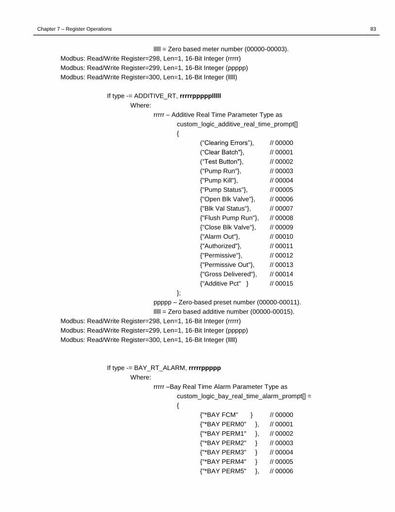
Chapter 7 – Register Operations 83
lllll = Zero based meter number (00000-00003).
Modbus: Read/Write Register=298, Len=1, 16-Bit Integer (rrrrr)
Modbus: Read/Write Register=299, Len=1, 16-Bit Integer (ppppp)
Modbus: Read/Write Register=300, Len=1, 16-Bit Integer (lllll)
If type -= ADDITIVE_RT, rrrrrppppplllll
Where:
rrrrr – Additive Real Time Parameter Type as
custom_logic_additive_real_time_prompt[]
{
(“Clearing Errors”), // 00000
(“Clear Batch"}, // 00001
(“Test Button"}, // 00002
("Pump Run"}, // 00003
{"Pump Kill"}, // 00004
{"Pump Status"}, // 00005
{"Open Blk Valve"}, // 00006
{"Blk Val Status"}, // 00007
{"Flush Pump Run"}, // 00008
{"Close Blk Valve"}, // 00009
{"Alarm Out"}, // 00010
{"Authorized"}, // 00011
{"Permissive"}, // 00012
{"Permissive Out"}, // 00013
{"Gross Delivered"}, // 00014
{"Additive Pct" } // 00015
};
ppppp – Zero-based preset number (00000-00011).
lllll = Zero based additive number (00000-00015).
Modbus: Read/Write Register=298, Len=1, 16-Bit Integer (rrrrr)
Modbus: Read/Write Register=299, Len=1, 16-Bit Integer (ppppp)
Modbus: Read/Write Register=300, Len=1, 16-Bit Integer (lllll)
If type -= BAY_RT_ALARM, rrrrrppppp
Where:
rrrrr –Bay Real Time Alarm Parameter Type as
custom_logic_bay_real_time_alarm_prompt[] =
{
{"*BAY FCM" } // 00000
{"*BAY PERM0" }, // 00001
{"*BAY PERM1" }, // 00002
{"*BAY PERM2" } // 00003
{"*BAY PERM3" } // 00004
{"*BAY PERM4" } // 00005
{"*BAY PERM5" }, // 00006

Chapter 7 – Register Operations 84
{"*BAY PERM6" } // 00007
{"*BAY PERM7" } // 00008
{"*ALL STOP" }, // 00009
{"*BAY PCM" }, // 00010
{"*PRNTR ERR" } // 00011
{"*BALARM 12" }, // 00012
{"*BALARM13" }, // 00013
{"*DEADMAN" }, // 00014
{"*FCM TRACE" }, // 00015
};
ppppp – Zero-based preset number (00000-00011).
Modbus: Read/Write Register=298, Len=1, 16-Bit Integer (rrrrr)
Modbus: Read/Write Register=299, Len=1, 16-Bit Integer (ppppp)
If type -= PRESET_RT_ALARM, rrrrrppppp
Where:
rrrrr –Preset Real Time Alarm Parameter Type as
custom_logic_preset_real_time_alarm_prompt[] =
{
{"*PRE FCM" }, // 00000
{"*PRE PERM" }, // 00001
{"*SWING ARM" }, // 00002
{"*NO LNFLSH" }, // 00003
{"*BLK VALVE" }, // 00004
{"*BAY ALARM" }, // 00005
{"*COMP ALRM" }, // 00006
{"*ADD ALARM" }, // 00007
{"*MTR STOP" }, // 00008
{"*OVERRUN" }, // 00009
{"*EXCESS FL" }, // 00010
};
ppppp – Zero-based preset number (00000-00011).
Modbus: Read/Write Register=298, Len=1, 16-Bit Integer (rrrrr)
Modbus: Read/Write Register=299, Len=1, 16-Bit Integer (ppppp)
If type -= COMPONENT_RT_ALARM, rrrrrppppplllll
Where:
rrrrr – Component Real Time Alarm Parameter Type as
custom_logic_component_real_time_alarm_prompt[] =
{
{"*COMP FCM" }, // 00000
{"*COMP PERM" }, // 00001
{"*BLK VALVE" }, // 00002
{"*UNAUTH FL" }, // 00003
{"*PUMP STAT" }, // 00004
{"*MTR ALARM" }, // 00005

Chapter 7 – Register Operations 85
{"*OVR BLEND" }, // 00006
{"*UND BLEND" }, // 00007
{"*API TABLE" }, // 00008
};
ppppp – Zero-based preset number (00000-00011).
lllll = Zero based component number (00000-00007).
Modbus: Read/Write Register=298, Len=1, 16-Bit Integer (rrrrr)
Modbus: Read/Write Register=299, Len=1, 16-Bit Integer (ppppp)
Modbus: Read/Write Register=300, Len=1, 16-Bit Integer (lllll)
If type -= METER_RT_ALARM, rrrrrppppplllll
Where:
rrrrr – Meter Real Time Alarm Parameter Type as
custom_logic_meter_real_time_alarm_prompt[] =
{
{"*MTR FCM" }, // 00000
{"*MTR PERM" }, // 00001
{"*FCM CONF" }, // 00002
{"*FCM WDT" }, // 00003
{"*FCM TMOUT" }, // 00004
{"*VALVE FLT" }, // 00005
{"*LOW FLOW" }, // 00006
{"*EXCESS FL" }, // 00007
{"*QUAD ENC" }, // 00008
{"*DENSITY" }, // 00009
{"*RTD ERROR" }, // 00010
{"*VALVE CTL" }, // 00011
{"*MTR CREEP" }, // 00012
{"*PRES ALRM" }, // 00013
{"*QUAD CH A" }, // 00014
{"*QUAD CH B" }, // 00015
{"*MTR COM" }, // 00016
{"*BSW" }, // 00017
{"*GRAVITY" }, // 00018
};
ppppp – Zero-based preset number (00000-00011).
lllll = Zero based meter number (00000-00003).
Modbus: Read/Write Register=298, Len=1, 16-Bit Integer (rrrrr)
Modbus: Read/Write Register=299, Len=1, 16-Bit Integer (ppppp)
Modbus: Read/Write Register=300, Len=1, 16-Bit Integer (lllll)
If type -= ADDITIVE_RT_ALARM, rrrrrppppplllll
Where:
rrrrr – Additive Real Time Alarm Parameter Type as
custom_logic_additive_real_time_alarm_prompt[]
{

Chapter 7 – Register Operations 86
{"*ADTV FCM" } // 00000
{"*ADTV PERM" }, // 00001
{"*UND ADTV" }, // 00002
{"*OVR ADTV" }, // 00003
{"*VALVE FLT" }, // 00004
{"*PUMP STAT" }, // 00005
{"*INJCT FLT" }, // 00006
{"*UNAUTH FL" }, // 00007
{"*NO LNFLSH" }, // 00008
{"*MTR CREEP" }, // 00009
{"*BLK VALVE" }, // 00010
};
ppppp – Zero-based preset number (00000-00011).
lllll = Zero based additive number (00000-00015).
Modbus: Read/Write Register=298, Len=1, 16-Bit Integer (rrrrr)
Modbus: Read/Write Register=299, Len=1, 16-Bit Integer (ppppp)
Modbus: Read/Write Register=300, Len=1, 16-Bit Integer (lllll)
If type -= ALWAYS_FALSE or ALWAYS_FALSE, (No Further Parameters)
If type -= ASSIGN or NOT, xxxxx
Where:
xxxxx = Custom logic index (0000-1023).
Modbus: Read/Write Register=298, Len=1, 16-Bit Integer (xxxxx)
If type -= any other valid type, xxxxxyyyyy
Where:
xxxxx = Custom logic index (0000-1023).
yyyyy = Custom logic index (0000-1023).
Modbus: Read/Write Register=298, Len=1, 16-Bit Integer (xxxxx)
Modbus: Read/Write Register=299, Len=1, 16-Bit Integer (yyyyy)
7.1.9 200 – STAND ALONE BOL DEFINITION REGISTERS
R200 => 0?0200aabbccddeeff
U200aabbccddeeff => 0?0200
Where:
aabb = BOL Line and Position Number for the BOL Number
ccdd = BOL Line and Position Number for the Card Number
eeff = BOL Line and Position Number for the Company
Modbus:
Read/Write Register=350, Len=1, 16-Bit Integer (aa)
Read/Write Register=351, Len=1, 16-Bit Integer (bb)
Read/Write Register=352, Len=1, 16-Bit Integer (cc)
Read/Write Register=353, Len=1, 16-Bit Integer (dd)

Chapter 7 – Register Operations 87
Read/Write Register=354, Len=1, 16-Bit Integer (ee)
Read/Write Register=355, Len=1, 16-Bit Integer (ff)
R201 => 0?0201aabbccddeeffgghh
U201aabbccddeeffgghh => 0?0201
Where:
aabb = BOL Line and Position Number for the Load Date
ccdd = BOL Line and Position Number for the Load Start Time
eeff = BOL Line and Position Number for the Load End Time
gghh = BOL Line and Position Number for the Corrected To
Modbus:
Read/Write Register=356, Len=1, 16-Bit Integer (aa)
Read/Write Register=357, Len=1, 16-Bit Integer (bb)
Read/Write Register=358, Len=1, 16-Bit Integer (cc)
Read/Write Register=359, Len=1, 16-Bit Integer (dd)
Read/Write Register=360, Len=1, 16-Bit Integer (ee)
Read/Write Register=361, Len=1, 16-Bit Integer (ff)
Read/Write Register=362, Len=1, 16-Bit Integer (gg)
Read/Write Register=363, Len=1, 16-Bit Integer (hh)
R202 => 0?0202aabbccddeeff
U202aabbccddeeff => 0?0202
Where:
aabb = BOL Line and Position Number for the Hazard Message
Modbus:
Read/Write Register=364, Len=1, 16-Bit Integer (aa)
Read/Write Register=365, Len=1, 16-Bit Integer (bb)
R203 => 0?0203aabbccddeeffgghhiijjkk
U203aabbccddeeffgghhiijjkk => 0?0203
Where:
aa = BOL Line Number to Start Product Totals
bb = BOL Position Number for the Product Code
cc = BOL Position Number for the Product Description
dd = BOL Position Number for the Product Gross Volume
ee = BOL Position Number for the Product Net Volume
ff = BOL Position Number for the Product Average Temp
gg = BOL Position Number for the Product Preset Number
hh = BOL Position Number for the Product Gravity/Density
ii = BOL Position Number for the Product Pressure
jj = BOL Position Number for the Product Alarm
kk = BOL Position Number for the Compartment Number
ll = BOL Position Number for the Exp Coeff
mm = BOL Position Number for the Corrected Gravity
nn = BOL Position Number for the Vcf Factor
oo = BOL Position Number for the BSW

Chapter 7 – Register Operations 88
pp = BOL Position Number for Batch Number
qq =BOL Position Number for Product Mass Volume
Modbus:
Read/Write Register=366, Len=1, 16-Bit Integer (aa)
Read/Write Register=367, Len=1, 16-Bit Integer (bb)
Read/Write Register=368, Len=1, 16-Bit Integer (cc)
Read/Write Register=369, Len=1, 16-Bit Integer (dd)
Read/Write Register=370, Len=1, 16-Bit Integer (ee)
Read/Write Register=371, Len=1, 16-Bit Integer (ff)
Read/Write Register=372, Len=1, 16-Bit Integer (gg)
Read/Write Register=373, Len=1, 16-Bit Integer (hh)
Read/Write Register=374, Len=1, 16-Bit Integer (ii)
Read/Write Register=375, Len=1, 16-Bit Integer (jj)
Note:
Exp Coeff, Corrected Gravity , Vcf Factor, BSW, Batch Number and Product Mass Volume not available for Modbus use.
R204 => 0?0204aabbccdd
U204aabbccddeeff => 0?0204
Where:
aabb = BOL Line and Position Number for the Total Product Gross Volume
ccdd = BOL Line and Position Number for the Total Product Net Volume
eeff = BOL Line and Position Number for the Total Product Mass Volume
Modbus:
Read/Write Register=376, Len=1, 16-Bit Integer (aa)
Read/Write Register=377, Len=1, 16-Bit Integer (bb)
Read/Write Register=378, Len=1, 16-Bit Integer (cc)
Read/Write Register=379, Len=1, 16-Bit Integer (dd)
Read/Write Register=N/A, Len=1, 16-Bit Integer (ee)
Read/Write Register=N/A, Len=1, 16-Bit Integer (ff)
Note:
Mass Positions are not available via Modbus protocol
R300iiill => 0?0300iiill…
U300iiill… => 0?0300iiill
Where:
iii = BOL Literal Line Index (0-29)
Note: For Modbus, the Modbus Custom Logic Index Register sets the iii index.
Modbus: Read/Write Register=417, Len=1, 16-Bit Integer (iii)
ll = BOL Line Number
… = Literal String (Max 80 Characters)
Modbus:
Read/Write Register=418, Len=1, 16-Bit Integer (ll)
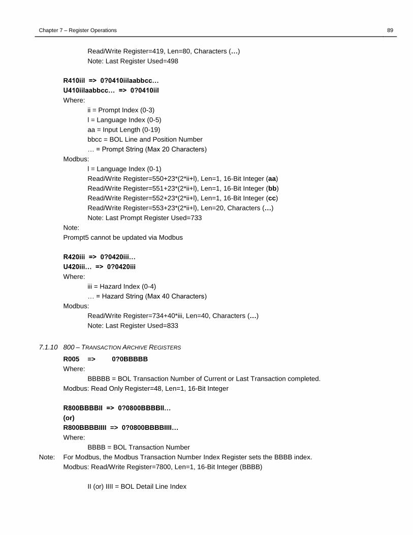
Chapter 7 – Register Operations 89
Read/Write Register=419, Len=80, Characters (…)
Note: Last Register Used=498
R410iil => 0?0410iilaabbcc…
U410iilaabbcc… => 0?0410iil
Where:
ii = Prompt Index (0-3)
l = Language Index (0-5)
aa = Input Length (0-19)
bbcc = BOL Line and Position Number
… = Prompt String (Max 20 Characters)
Modbus:
l = Language Index (0-1)
Read/Write Register=550+23*(2*ii+l), Len=1, 16-Bit Integer (aa)
Read/Write Register=551+23*(2*ii+l), Len=1, 16-Bit Integer (bb)
Read/Write Register=552+23*(2*ii+l), Len=1, 16-Bit Integer (cc)
Read/Write Register=553+23*(2*ii+l), Len=20, Characters (…)
Note: Last Prompt Register Used=733
Note:
Prompt5 cannot be updated via Modbus
R420iii => 0?0420iii…
U420iii… => 0?0420iii
Where:
iii = Hazard Index (0-4)
… = Hazard String (Max 40 Characters)
Modbus:
Read/Write Register=734+40*iii, Len=40, Characters (…)
Note: Last Register Used=833
7.1.10 800 – TRANSACTION ARCHIVE REGISTERS
R005 => 0?0BBBBB
Where:
BBBBB = BOL Transaction Number of Current or Last Transaction completed.
Modbus: Read Only Register=48, Len=1, 16-Bit Integer
R800BBBBII => 0?0800BBBBII…
(or)
R800BBBBIIII => 0?0800BBBBIIII…
Where:
BBBB = BOL Transaction Number
Note: For Modbus, the Modbus Transaction Number Index Register sets the BBBB index.
Modbus: Read/Write Register=7800, Len=1, 16-Bit Integer (BBBB)
II (or) IIII = BOL Detail Line Index

Chapter 7 – Register Operations 90
Note: For Modbus, the Modbus Transaction Detail Index Register sets the IIII index.
Modbus: Read/Write Register=7801, Len=1, 16-Bit Integer (IIII)
… = Type Specific Parameters
if BOL Detail Line Index = 00,
IIBBBBnnnn(10)oosssspppptttteeaaaa(25)bbbb(25)cccc(25)dddd(25)eeee(25)
(or)
IIIIBBBBnnnn(10)oosssspppptttteeaaaa(25)bbbb(25)cccc(25)dddd(25) eeee(25)
II (or) IIII = BOL Detail Line Index
BBBB = BOL Transaction Number
nnnn = Card Number (10 Characters)
oo = Company Number
ssss = Load Start Time
pppp = Load Stop Time
tttt = Load Date
ee = Number of Details in Transaction
aaaa = Driver Prompt #1 Value (25 Characters)
bbbb = Driver Prompt #2 Value (25 Characters)
cccc = Driver Prompt #3 Value (25 Characters)
dddd = Driver Prompt #4 Value (25 Characters)
eeee = Driver Prompt #5 Value (25 Characters)
Modbus:
Read/Write Register=7810, Len=2, 32-Bit Integer (nnnn)
Read/Write Register=7812, Len=1, 16-Bit Integer (oo)
Read/Write Register=7813, Len=1, 16-Bit Integer (ssss)
Read/Write Register=7814, Len=1, 16-Bit Integer (pppp)
Read/Write Register=7815, Len=1, 16-Bit Integer (tttt)
Read/Write Register=7816, Len=1, 16-Bit Integer (ee)
Read/Write Register=7817, Len=25, Characters (aaaa)
Read/Write Register=7842, Len=25, Characters (bbbb)
Read/Write Register=7867, Len=25, Characters (cccc)
Read/Write Register=7892, Len=25, Characters (dddd)
Read/Write Register=N/A, Len=25, Characters (eeee)
if BOL Detail Line Index > 00,
IIBBBBppptthhhccccccgggggggggnnnnnnnnnttttddddmmrrrrssssssttttuuuuuvvvvvwww
(or)
IIIIBBBBppptthhhccccccgggggggggnnnnnnnnnttttddddmmrrrrssssssttttuuuuuvvvvvwww
II (or) IIII = BOL Detail Line Index
BBBB = BOL Transaction Number
ppp = Preset Number
tt = Detail Type,
„1‟ – Saleable Product,
„2‟ – Component,

Chapter 7 – Register Operations 91
„3‟ – Additive,
„4‟ – Meter,
„5‟ – Preset Totalizer,
„6‟ – Meter Totalizer,
„7‟ – Component Totalizer,
„8‟ – Additive Totalizer
hhh = Legacy Header Index (not used)
cccccc = Product Code
ggggggggg = Gross Volume
nnnnnnnnn = Net Volume
Note: if the Use Hundredths W&M RCU parameter is enabled, the gross and net quantity value will have an implied two decimal places.
tttt = Average Temp
dddd = Gravity or Density
mm = Compartment
rrrr = Average Pressure
ssssss = api_expansion_coef_tenths
ttttt = corrected_densitygravity
uuuuu = volume_correction_factor
vvvvv = bsw_hund
wwww = alibilog_alarm
xxxxxxxx = batch_number
zzzzzzzzz = mass_del
Modbus:
Read/Write Register=7810, Len=1, 16-Bit Integer (ppp)
Read/Write Register=7811, Len=1, 16-Bit Integer (tt)
Read/Write Register=7812, Len=6, Characters (cccccc)
Read/Write Register=7818, Len=2, 32-Bit Integer (ggggggggg)
Read/Write Register=7820, Len=2, 32-Bit Integer (nnnnnnnnn)
Read/Write Register=7822, Len=1, 16-Bit Integer (ttttt)
Read/Write Register=7823, Len=1, 16-Bit Integer (dddd)
Read/Write Register=7824, Len=1, 16-Bit Integer (mm)
Read/Write Register=7825, Len=1, 16-Bit Integer (rrrr)
Read/Write Register=7826, Len=1, 16-Bit Integer (sssss)
Read/Write Register=7827, Len=1, 16-Bit Integer (tttt)
Read/Write Register=7828, Len=1, 16-Bit Integer (uuuuu)
Read/Write Register=7829, Len=1, 16-Bit Integer (vvvvv)
Read/Write Register=7830, Len=1, 16-Bit Integer (wwww)
Read/Write Register=7831, Len=1, 16-Bit Integer (xxxxxxx)
Read/Write Register=7832, Len=1, 16-Bit Integer (zzzzzzzzz)
7.2 SPECIAL PURPOSE REGISTERS
7.2.1 000 – MULTILOAD FIRMWARE VERSION
R000 => 0?0sssssssssssssssssss
Where:
sssssssssssssssssss = Firmware Identification

Chapter 7 – Register Operations 92
000MultiLoad II v3.31.xx Jan xx 2011
000MultiLoad II v4.31.xx Jan xx 2011
000MultiLoad 1Arm v3.31.xx Jan xx 2011 (discontinued)
000MultiLoad 1Arm v4.31.xx Jan xx 2011 (discontinued)
000MultiLoad Mobl v3.31.xx Jan xx 2011
000MultiLoad Mobl v4.31.xx Jan xx 2011
000MultiLoad SMP v3.31.xx Jan xx 2011
000MultiLoad SMP v4.31.xx Jan xx 2011
Modbus: Read Only Register=000, Len=35, Characters (sssssssssssssssssss)
7.2.2 001 – DATE AND TIME
R001 => 0?0001YYMMDDHHMMSS
U001YYMMDDHHMMSS => 0?0
Where:
YY = Year (00-99).
MM = Month (01-12)
DD = Day (01-32)
HH = Hours (00-23)
MM = Minutes (00-59)
SS = Seconds (00-59)
Note: Update will only occur if new time is different from current time by number of seconds specified by R014 (Min Time Change Secs).
Modbus: Read/Write Register=035, Len=12, Characters (YYMMDDHHMMSS)
7.2.3 003 – FCM POLL RATE
R003 => 0?0DD
Where:
DD = Average number of FCMs polled per second.
Modbus: Read Only Register=047, Len=1, 16-Bit Integer
7.2.4 005 – CURRENT BOL/TICKET NUMBER
R005 => 0?0DDDDD
Where:
DDDDD = Current BOL/Ticket Number.
Modbus: Read Only Register=048, Len=1, 16-Bit Integer
7.2.5 070 – ETHERNET ENABLE
R070 => 0?0070DDDDDDDDD
U070DDDDDDDDD => 0?0
Where:
DDDDDDDDD = (000000000 = Disabled), (000000001 = Enabled)
Modbus: Read/Write Register=049, Len=1, 16-Bit Integer

Chapter 7 – Register Operations 93
7.2.6 071 – IP ADDRESS
R071 => 0?0071DDD.DDD.DDD.DDD
U071DDD.DDD.DDD.DDD => 0?0
Where:
DDD.DDD.DDD.DDD = IP Address
Modbus: Read/Write Register=050, Len=2, 32-Bit Integer (4 8-bit numbers)
7.2.7 072 – IP MASK
R072 => 0?0072DDD.DDD.DDD.DDD
U072DDD.DDD.DDD.DDD => 0?0
Where:
DDD.DDD.DDD.DDD = IP Mask
Modbus: Read/Write Register=052, Len=2, 32-Bit Integer (4 8-bit numbers)
7.2.8 073 – IP GATEWAY
R073 => 0?0073DDD.DDD.DDD.DDD
U073DDD.DDD.DDD.DDD => 0?0
Where:
DDD.DDD.DDD.DDD = IP Gateway
Modbus: Read/Write Register=054, Len=2, 32-Bit Integer (4 8-bit numbers)
7.2.9 074 – IP HOST
R074 => 0?0074DDD.DDD.DDD.DDD
U074DDD.DDD.DDD.DDD => 0?0
Where:
DDD.DDD.DDD.DDD = IP Host
Modbus: Read/Write Register=056, Len=2, 32-Bit Integer (4 8-bit numbers)
7.2.10 076 – ADMIN PASSWORD
Use the Extended Service Register to change the value
7.2.11 077 – USER PASSWORD
Use the Extended Service Register to change the value
7.2.12 085 – MODEM INITIALIZATION STRING
R085 => 0?0085SSS...
U085SSS… => 0?0
Where:
SSS = ASCII Modem Initialization String (Default "AT&F0&B1&C1&D0S0=1")
Modbus: Read/Write Register=058, Len=40, Characters (SSS…), Null Terminated

Chapter 7 – Register Operations 94
7.2.13 091..093 – COMMUNICATION PORT PARAMETERS
R09p => 0?009pSDPTAC
U09pSDPTAC => 0?0
Where:
p = Communication Port (1-3)
S = Communication Speed
„0‟ = 300 BAUD
„1‟ = 1200 BAUD
„2‟ = 2400 BAUD
„3‟ = 4800 BAUD
„4‟ = 9600 BAUD
„5‟ = 19.2K BAUD
„6‟ = 38.4K BAUD
„7‟ = 57.6K BAUD
„8‟ = 115K BAUD
„9‟ = 230K BAUD
D = Data Bits
„0‟ = 7 Data Bits
„1‟ = 8 Data Bits
P = Parity
„0‟ = None
„1‟ = Odd
„2‟ = Even
T = Stop Bits
„1‟ = 1 Stop Bit
„2‟ = 2 Stop Bits
A = Port Assignment
„0‟ = Not in Use
„1‟ = Host
„2‟ = FCMs
„3‟ = Printer
„4‟ = Event Log Printer
„5‟ = Ethernet Pass Thru
„6‟ = Alibi Log
„7‟ = MASS METER PORT
„8‟ = GPS (MultiLoad Mobile Only)
„9‟ = ALIBI LOG PTB PORT
C = Connection Type
„0‟ = Single/Master
„1‟ = Multi-dropped Slave
„2‟ = 2-Wire RS485
Modbus:
p=0, Read/Write Register=243, Len=6, Characters (SDPTAC)
p=1, Read/Write Register=249, Len=6, Characters (SDPTAC)

Chapter 7 – Register Operations 95
p=2, Read/Write Register=255, Len=6, Characters (SDPTAC)
7.2.14 095..099 – PROGRAM MODE PASSWORDS (5)
R095 => 0?0095SSSSSSS
U095SSSSSSS => 0?0
Where:
SSSSSSS = ASCII Password String (Default “00000”)
Modbus:
Read/Write Register=261, Len=7, Characters (SSSSSSS), Null Terminated
Read/Write Register=268, Len=7, Characters (SSSSSSS), Null Terminated
Read/Write Register=275, Len=7, Characters (SSSSSSS), Null Terminated
Read/Write Register=282, Len=7, Characters (SSSSSSS), Null Terminated
Read/Write Register=289, Len=7, Characters (SSSSSSS), Null Terminated
7.2.15 112 - REAL-TIME PRESET TOTAL GROSS TOTALIZERS
R112ppp => 0?0112pppPPPPPPPPPMMMMMMMMM…CCCCCCCCC…AAAAAAAAA
Where:
ppp = The specified zero-based preset or load arm number (000-011).
PPPPPPPPP = Preset Total Gross Totalizer
MMMMMMMMM… = Meter Total Gross Totalizers (at least 4 meters, 9 digits per totalizer.)
CCCCCCCCC… = Component Total Gross Totalizers (8 components, 9 digits per totalizer.)
Note: if the Use Hundredths W&M RCU parameter is enabled, the preset, meter and component gross quantity values will have an implied two decimal places.
AAAAAAAAA… = Additive Total Gross Totalizers in Thousands, (16 additives, 9 digits per totalizer.)
Modbus:
Where: p = preset (0-11), m = meter (0-4), c = component (0-7), a=additive (0-15)
Read Only Registers=3000+2*p, Len=2, 32-Bit Integer (PPPPPPPPP)
Read Only Registers=3024+2*(5*p+m), Len=2, 32-Bit Integer (MMMMMMMMM)
Read Only Registers=3144+2*(8*p+c), Len=2, 32-Bit Integer (CCCCCCCCC)
Read Only Registers=3336+2*(16*p+a), Len=2, 32-Bit Integer (AAAAAAAAA)
Note: Last Gross Totalizer register used=3719
7.2.16 113 - REAL-TIME PRESET TOTAL NET TOTALIZERS
R113ppp => 0?0113pppPPPPPPPPPCCCCCCCCC…
Where:
ppp = The specified zero-based preset or load arm number (000-011).
PPPPPPPPP = Preset Total Net Totalizer
CCCCCCCCC… = Component Total Net Totalizers (8 components, 9 digits per totalizer.)
Note: if the Use Hundredths W&M RCU parameter is enabled, the preset and component net quantity values will have an implied two decimal places.
Modbus:
Where: p = preset (0-11), c = component (0-7)
Read Only Registers=3720+2*p, Len=2, 32-Bit Integer (PPPPPPPPP)
Read Only Registers=3744+2*(8*p+c), Len=2, 32-Bit Integer (CCCCCCCCC)
Note: Last Net Totalizer register used=3935

Chapter 7 – Register Operations 96
7.2.17 114 - REAL-TIME PRESET TOTAL MASS TOTALIZERS
R114ppp => 0?0114pppPPPPPPPPPCCCCCCCCC…
Where:
ppp = The specified zero-based preset or load arm number (000-011).
PPPPPPPPP = Preset Total Mass Totalizer
CCCCCCCCC… = Component Total Mass Totalizers (8 components, 9 digits per totalizer.)
Note: if the Use Hundredths W&M RCU parameter is enabled, the preset and component mass quantity values will have an implied two decimal places.
Modbus:
Where: p = preset (0-11), c = component (0-7)
Read Only Registers=11720+2*p, Len=2, 32-Bit Integer (PPPPPPPPP)
Read Only Registers=11744+2*(8*p+c), Len=2, 32-Bit Integer (CCCCCCCCC)
Note: Last Mass Totalizer register used=11935
7.2.18 133 – FCM IO ACCESS
R133fffppp => 0?0133fffpppc…
Where:
fff = FCM number (000-031).
ppp = FCM port number (0-35)
c = FCM com, „0‟ FCM COM ok, „1‟ FCM COM error.
… = Type Specific Replies
if FCM port number is 0..7, d
Where:
d = State of Digital Port („0‟ – Off, „1‟ – On)
if FCM port number is 8, fffff
Where:
ffff = Raw frequency/digital value from Opto 22 Analog Module
if FCM port number is 9, sfffff
Where:
sttttt = Temp in Hundreds from Opto 22 RTD Analog Module
(no offset added)
if FCM port number is 10, sttttt
Where:
sttttt = Temp in Hundreds from Toptech RTD Module, FCM II
or I/O Board (no offset added)
Note: All Temps in C or F depending on Register R100003 ("Temps in F").
if FCM port number is 20..35, d (this is used to access I/O board ports and FCM II expander ports > 7)
Where:
d = State of Digital Port (s-20) („0‟ – Off, „1‟ – On)
Modbus:
Supported through Modbus Extended Services Registers.
U133fffpppd => 0?0133fff

Chapter 7 – Register Operations 97
Where:
fff = FCM number (000-031).
ppp = FCM port number (0-35)
d = Set new state of digital port („0‟ – Off, „1‟ – On)
Note: States commanded with R133 are OR‟d with any other functionality already assigned to the port)
7.2.19 140 –CURRENT LATITUDE/LONGITUDE POSITION REGISTERS (MULTILOAD MOBILE ONLY)
R140 => 0?0140+lllllllll+ooooooooo
Where:
+lllllllll = Current Latitude Position.
+ooooooooo = Current Longitude Position.
Note: Latitude format (S 90 to N 90) is:
if Latitude >= 0 then "N" else "S"
integer_degrees = abs(Latitude) / 60000
float_minutes = (abs(Latitude) % 60000) / 1000
Note: Longitude format (180 E to 180 W) is:
if Longitude >= 0 then "E" else "W"
integer_degrees = abs(Longitude) / 60000
float_minutes = (abs(Longitude) % 60000) / 1000
Note: Latitude & Longitude = 999999999 when no valid data available.
Modbus:
Read Only Registers=310, Len=2, 32-Bit Signed Integer (+lllllllll)
Read Only Registers=312, Len=2, 32-Bit Signed Integer (+ooooooooo)
7.2.20 141 – CURRENT TRANSACTION LATITUDE/LONGITUDE/SITE INDEX REGISTERS (MULTILOAD MOBILE ONLY)
R141 => 0?0141+lllllllll+ooooooooosssssssss
Where:
+lllllllll = Current Transaction Latitude Position.
+ooooooooo = Current Transaction Longitude Position.
sssssssss = Current Transaction Site Index (GPS Site Database).
Note: Updated on transaction authorization (T<esc>A).
Note: Latitude format (S 90 to N 90) is:
if Latitude >= 0 then "N" else "S"
integer_degrees = abs(Latitude) / 60000
float_minutes = (abs(Latitude) % 60000) / 1000
Note: Longitude format (180 E to 180 W) is:
if Longitude >= 0 then "E" else "W"
integer_degrees = abs(Longitude) / 60000
float_minutes = (abs(Longitude) % 60000) / 1000
Note: Site Index = +999999999 when no site match exists.
Modbus:
Read Only Registers=314, Len=2, 32-Bit Signed Integer (+lllllllll)
Read Only Registers=316, Len=2, 32-Bit Signed Integer (+ooooooooo)
Read Only Registers=318, Len=2, 32-Bit Unsigned Integer (sssssssss)

Chapter 7 – Register Operations 98
7.2.21 400 - PRESET DEFINITION REGISTERS
R400ppp => 0?0400pppNNNNNNNNNNCCC…AAA…PPP…RRR…
U400pppNNNNNNNNNNCCC…AAA…PPP… => 0?0
Where:
ppp = The specified zero-based preset or load arm number (000-011).
NNNNNNNNNN = 10 Character Preset Name
CCC… = Component Product Index (500 register) for each component (8 component indices, 3 digits per index.)
AAA… = Additive Product Index (500 register) for each additive (16 additive indices, 3 digits per index.)
RRR… = Standalone Authorized Product Index (500 register) (33 product indices, 3 digits per index.)
Modbus:
Where: p = preset (0-11), c = component (0-7), a = additive (0-15)
Read/Write Registers=8000+67*p, Len=10, Characters (NNNNNNNNNN), Null Terminated
Read/Write Registers=8010+67*p+c, Len=1, 16-Bit Integer (CCC…)
Read/Write Registers=8018+67*p+a, Len=1, 16-Bit Integer (AAA…)
Read/Write Registers=8034+67*p+r, Len=1, 16-Bit Integer (RRR…)
Note: Last Preset Definition register used=8805
7.2.22 401 – EXTERNAL PRESET DISPLAY REGISTER
R401ppp => 0?0400pppllllllllllPPPPPPPPPVVVVVVVVVssssssssss
U401pppllllllllllPPPPPPPPPVVVVVVVVVssssssssss => 0?0
Where:
ppp = external preset number, number must follow last multiload preset # defined.
llllllllll = 10 character product string.
PPPPPPPPP = 9 character preset volume (note only digits will be displayed).
VVVVVVVVV = 9 character delivered volume (note only digits will be displayed).
ssssssssss = 10 character status string.
This interface will allow a host to display other preset volumes, separate from ML values on the load screen. These values will be maintained in a different color to clearly establish them as not legal relevant and that they should not be used for trade.
A new bay parameter "Number External Presets" is used to specify how many external presets should be displayed.
External Preset Load Screen Data will be updated when this command is received.
When an external preset is selected, the state will go to a 'a'-'h' matching the preset number.
MAMppp - can be sent by the host to return to the load screen when done driving the screen.
Modbus:
Supported through Modbus Extended Services Registers.
7.2.23 500 - PRODUCT DEFINITION REGISTERS
R500iii => 0?0500iiiHCCCCCCLLLLLLLLLLLLLLLLLLLLLLLLLDDDDDDDDDDCCCPPPPP…AAAPPPPP…
U500iiiHCCCCCCLLLLLLLLLLLLLLLLLLLLLLLLLDDDDDDDDDDCCCPPPPP…AAAPPPPP… => 0?0
Where:

Chapter 7 – Register Operations 99
iii = The specified zero based product index (000-099).
Note: For Modbus, the Modbus Product Definition Index Register sets the iii index.
Modbus: Read/Write Register=2200, Len=1, 16-Bit Integer (iii)
H = Hazard Index (stand alone use only).
CCCCCC = 6 Character Product Code.
LLLLLLLLLLLLLLLLLLLLLLLLL = 25 Character Long Product Description.
DDDDDDDDDD = 10 Character Product Description.
CCCPPPPP = Component Product Definition Index (CCC) & Component Percent with an implied two decimal places (i.e. 01234 => 012.34%) (8 component CCCPPPPP pairs).
AAAPPPPP = Additive Product Definition Index (AAA) & Additive Percent with an implied four decimal places (i.e. 12345 => 1.2345%) (up to 12 additive AAAPPPPP pairs). Note: Max Additive Percentage is 6.5535%.
Modbus:
Where: c = component (0-7), a = additive (0-11)
Read/Write Register=2201, Len=1, 16-Bit Integer (H)
Read/Write Register=2202, Len=6, Characters (CCCCCC)
Read/Write Register=2208, Len=25, Characters (LLLLLLLLLLLLLLLLLLLLLLLLL)
Read/Write Register=2233, Len=10, Characters (DDDDDDDDDD)
Read/Write Register=2243+2*c, Len=1, 16-Bit Integer (CCC)
Read/Write Register=2244+2*c, Len=1, 16-Bit Integer (PPPPP)
Read/Write Register=2259+2*a, Len=1, 16-Bit Integer (AAA)
Read/Write Register=2260+2*a, Len=1, 16-Bit Integer (PPPPP)
Note: Last Product Definition register used=2271 (only 6 additives)
7.2.24 600 - STANDALONE DRIVER CARD DATABASE
R600iii => 0?0600iiiccccccccppppmmlbbbbbbbbbbbbbbbb
U600iiiccccccccppppmmlbbbbbbbbbbbbbbbb => 0?0
Where:
iii = Card database index (1 – 300)
Note: For Modbus, the Modbus Card Database Index Register sets the iii index.
Modbus: Read/Write Register=2300, Len=1, 16-Bit Integer (iii)
cccccccc = Card Number
pppp = PIN Number
mm = Company Id (unused)
l = Language Index (0 or 1)
bbbbbbbbbbbbbbbb = Preset lockouts as 16 bit binary number
(For example 0000000000000011 = preset 1 & 2 locked out for driver)
Modbus:
Read/Write Register=2301, Len=2, 32-Bit Integer (cccccccc)
Read/Write Register=2303, Len=1, 16-Bit Integer (pppp)
Read/Write Register=2304, Len=1, 16-Bit Integer (mm)
Read/Write Register=2305, Len=1, 16-Bit Integer (l)
Read/Write Register=2306, Len=1, 16-Bit Integer (bbbbbbbbbbbbbbbb)

Chapter 7 – Register Operations 100
7.2.25 650 –GPS SITE DATABASE (MULTILOAD MOBILE ONLY)
R650iiiiiiiii => 0?0650iiiiiiiiinnnnnnnnnnnnnnn+lllllllll+ooooooooo
U650iiiiiiiiinnnnnnnnnnnnnnn+lllllllll+ooooooooo => 0?00?0650iiiiiiiiinnnnnnnnnnnnnnn+lllllllll+ooooooooo
Where:
iiiiiiiii = Site Index (000000000-000003999)
Note: For Modbus, the Modbus GPS Site Database Index Register sets the iiiiiiiii index.
Modbus: Read/Write Register=2350, Len=1, 16-Bit Integer (iiiiiiiii)
nnnnnnnnnnnnnnn = Site Name (15 Characters Padded)
+lllllllll = Site Latitude Position.
+ooooooooo = Site Longitude Position.
Note: An Update to index 0 will clear the entire list.
Note: Latitude format (S 90 to N 90) is:
if Latitude >= 0 then "N" else "S"
integer_degrees = abs(Latitude) / 60000
float_minutes = (abs(Latitude) % 60000) / 1000
Note: Longitude format (180 E to 180 W) is:
if Longitude >= 0 then "E" else "W"
integer_degrees = abs(Longitude) / 60000
float_minutes = (abs(Longitude) % 60000) / 1000
Modbus:
Read/Write Register=2351, Len=15, Characters (nnnnnnnnnnnnnnn)
Read/Write Register=2366, Len=2, 32-Bit Signed Integer (+lllllllll)
Read/Write Register=2368, Len=2, 32-Bit Signed Integer (+ooooooooo)
7.2.26 700 - CONFIGURABLE LANGUAGE PROMPTS
R700iil => 0?0700iilsss…
U700iilsss… => 0?0
Where:
ii = Prompt Index with defaults as:
00 = "Insert driver card..."
01 = "For Access"
02 = "Invalid Driver..."
03 = "Remove Card..."
04 = "Please Wait..."
07 = "Press 'A' key to Begin..."
19 = "A=Next B=Prev C=Abort D=Pick"
20= "System Unavailable"
28 = "PRE PRODUCT SET DEL STATUS "
35 = "" // Alternate Load Screen Footer
Note: For Modbus, the Modbus Language Prompt Index Register sets the ii index.
Modbus: Read/Write Register=2400, Len=1, 16-Bit Integer (ii)
l = Language Index (0 or 1)

Chapter 7 – Register Operations 101
Note: For Modbus, the Modbus Language Prompt Language Index Register sets the l index.
Modbus: Read/Write Register=2401, Len=1, 16-Bit Integer (l)
sss… = Prompt string (40 ASCII characters or 20 UTF-8 characters, 3-bytes each)
Note: if prompt string empty, null, built in prompt will be used based on language setting.
Note: only the prompts listed above can be changed.
Modbus:
Read/Write Register=2402, Len=60, Characters (sss…)
7.2.27 710 - BAY ALARM MESSAGES
R710iii => 0?0710iiilllllsssssssssssssssssssssssssssssscccccppppprrrrrttttt
U710iiilllllssssssssssssssssssssssssssssss => 0?0
U710iiilllllsssssssssssssssssssssssssssssscccccppppprrrrr => 0?0
U710iiilllllsssssssssssssssssssssssssssssscccccppppprrrrrttttt => 0?0
Where:
iii = Alarm Index with defaults as:
struct alarm_def factory_bay_alarm[31] =
{
{"*BAY FCM" , AUTO_CLEAR}, // 710000
{"*GROUND ", AUTO_CLEAR}, // 710001
{"*VRU ", AUTO_CLEAR}, // 710002
{"*OVERFILL ", AUTO_CLEAR}, // 710003
{"*ESD PERM ", AUTO_CLEAR}, // 710004
{"*BAY PERM4", AUTO_CLEAR}, // 710005
{"*BAY PERM5", AUTO_CLEAR}, // 710006
{"*BAY PERM6", AUTO_CLEAR}, // 710007
{"*BAY PERM7", AUTO_CLEAR}, // 710008
{"*ALL STOP" , AUTO_CLEAR}, // 710009
{"*BAY PCM ", AUTO_CLEAR}, // 710010
{"*PRNTR ERR", AUTO_CLEAR}, // 710011
{"*GPS ERROR", AUTO_CLEAR}, // 710012 (MultiLoad Mobile Only)
{"*BALARM 13", DRIVER_CLEAR}, // 710013
{"*BALARM 14", DRIVER_CLEAR}, // 710014
{"*FCM TRACE", DRIVER_CLEAR}// 710015
};
Note: For Modbus, the Modbus Bay Alarm Index Register sets the iii index.
Modbus: Read/Write Register=2500, Len=1, 16-Bit Integer (iii)
lll = Alarm Level as:
enum
{
AUTO_CLEAR = 0,
DRIVER_CLEAR = 1,
REMOTE_CLEAR = 2,
PROGRAM_CLEAR = 3,

Chapter 7 – Register Operations 102
WM_CLEAR = 4
}alarm_level;
ssssssssssssssssssssssssssssss = Alarm Message (prefix with an *)
Note: Up to 30 UTF-8 bytes to represent a max of 10 characters.
ccccc = Promotion Count (00000=no promotion)
ppppp = Promoted Alarm Level as:
enum
{
AUTO_CLEAR = 0,
DRIVER_CLEAR = 1,
REMOTE_CLEAR = 2,
PROGRAM_CLEAR = 3,
WM_CLEAR = 4
}promoted_alarm_level;
rrrrr = Reset Mode as:
enum
{
AUTH_TRANS = 0,
CLEAR_PROMOTED = 1,
TIME_2_MIN = 2,
TIME_5_MIN = 3,
TIME_15_MIN = 4,
TIME_30_MIN = 5,
TIME_60_MIN = 6,
TIME_3_HOURS = 7,
TIME_6_HOURS = 8,
TIME_12_HOURS = 9,
TIME_24_HOURS = 10,
}alarm_count_reset_mode;
ttttt = Alarm_to_host as
enum
{
REMOTE = 0,
LOCAL =1,
}alarm_to_host_mode_type
Note: only permissive names can be changed, iii=1..8
Modbus:
Read/Write Register=2501, Len=1, 16-Bit Integer (lllll)
Read/Write Register=2502, Len=15, Characters (sssssssssssssss)
Note: Up to 15 UTF-8 bytes to represent a max of 10 characters.
Read/Write Register=2517, Len=1, 16-Bit Integer (ccccc)
Read/Write Register=2518, Len=1, 16-Bit Integer (ppppp)
Read/Write Register=2519, Len=1, 16-Bit Integer (rrrrr)
Read/Write Register=cannot be accessed, Len=1, 16-Bit Integer (ttttt)

Chapter 7 – Register Operations 103
7.2.28 711 - PRESET ALARM MESSAGES
R711iii => 0?0711iiilllllsssssssssssssssssssssssssssssscccccppppprrrrrttttt
U711iiilllllssssssssssssssssssssssssssssss => 0?0
U711iiilllllsssssssssssssssssssssssssssssscccccppppprrrrr => 0?0
U711iiilllllsssssssssssssssssssssssssssssscccccppppprrrrrttttt => 0?0
Where:
iii = Alarm Index with defaults as:
struct alarm_def factory_preset_alarm[31] =
{
{"*PRE FCM" , AUTO_CLEAR}, // 711000
{"*PRE PERM" , AUTO_CLEAR}, // 711001
{"*SWING ARM", AUTO_CLEAR}, // 711002
{"*NO LNFLSH", DRIVER_CLEAR}, // 711003
{"*PALARM 04", DRIVER_CLEAR}, // 711004
{"*BAY ALARM", AUTO_CLEAR}, // 711005
{"*COMP ALRM", AUTO_CLEAR}, // 711006
{"*ADD ALARM", AUTO_CLEAR}, // 711007
{"*MTR STOP" , AUTO_CLEAR}, // 711008
{"*OVERRUN" , REMOTE_CLEAR}, // 711009
{"*EXCESS FL", REMOTE_CLEAR}, // 711010
{"*PALARM 11", DRIVER_CLEAR}, // 711011
{"*PALARM 12", DRIVER_CLEAR}, // 711012
{"*PALARM 13", DRIVER_CLEAR}, // 711013
{"*PALARM 14", DRIVER_CLEAR}, // 711014
{"*INVCONFIG", AUTO_CLEAR} // 711015
};
Note: For Modbus, the Modbus Preset Alarm Index Register sets the iii index.
Modbus: Read/Write Register=2520, Len=1, 16-Bit Integer (iii)
lll = Alarm Level as:
enum
{
AUTO_CLEAR = 0,
DRIVER_CLEAR = 1,
REMOTE_CLEAR = 2,
PROGRAM_CLEAR = 3,
WM_CLEAR = 4
}alarm_level;
ssssssssssssssssssssssssssssss = Alarm Message (prefix with an *)
Note: Up to 30 UTF-8 bytes to represent a max of 10 characters.
ccccc = Promotion Count (00000=no promotion)
ppppp = Promoted Alarm Level as:
enum
{
AUTO_CLEAR = 0,

Chapter 7 – Register Operations 104
DRIVER_CLEAR = 1,
REMOTE_CLEAR = 2,
PROGRAM_CLEAR = 3,
WM_CLEAR = 4
}promoted_alarm_level;
rrrrr = Reset Mode as:
enum
{
AUTH_TRANS = 0,
CLEAR_PROMOTED = 1,
TIME_2_MIN = 2,
TIME_5_MIN = 3,
TIME_15_MIN = 4,
TIME_30_MIN = 5,
TIME_60_MIN = 6,
TIME_3_HOURS = 7,
TIME_6_HOURS = 8,
TIME_12_HOURS = 9,
TIME_24_HOURS = 10,
}alarm_count_reset_mode;
ttttt = Alarm_to_host as
enum
{
REMOTE = 0,
LOCAL =1,
}alarm_to_host_mode_type
Note: only permissive names can be changed, iii=1.
Modbus:
Read/Write Register=2521, Len=1, 16-Bit Integer (lllll)
Read/Write Register=2522, Len=15, Characters (sssssssssssssss)
Note: Up to 15 UTF-8 bytes to represent a max of 10 characters.
Read/Write Register=2537, Len=1, 16-Bit Integer (ccccc)
Read/Write Register=2538, Len=1, 16-Bit Integer (ppppp)
Read/Write Register=2539, Len=1, 16-Bit Integer (rrrrr)
Read/Write Register=cannot be accessed, Len=1, 16-Bit Integer (ttttt)
7.2.29 712 - METER ALARM MESSAGES
R712iii => 0?0712iiilllllsssssssssssssssssssssssssssssscccccppppprrrrrttttt
U712iiilllllssssssssssssssssssssssssssssss => 0?0
U712iiilllllsssssssssssssssssssssssssssssscccccppppprrrrr => 0?0
U712iiilllllsssssssssssssssssssssssssssssscccccppppprrrrrttttt => 0?0
Where:
iii = Alarm Index with defaults as:
struct alarm_def factory_meter_alarm[31] =
{
{"*MTR FCM" , AUTO_CLEAR}, // 712000

Chapter 7 – Register Operations 105
{"*MTR PERM" , AUTO_CLEAR}, // 712001
{"*FCM CONF" , REMOTE_CLEAR}, // 712002
{"*FCM WDT" , REMOTE_CLEAR}, // 712003
{"*FCM TMOUT", REMOTE_CLEAR}, // 712004
{"*VALVE FLT", PROGRAM_CLEAR}, // 712005
{"*LOW FLOW" , DRIVER_CLEAR}, // 712006
{"*EXCESS FL", REMOTE_CLEAR}, // 712007
{"*QUAD ENC" , REMOTE_CLEAR}, // 712008
{"*FCM PERM" , DRIVER_CLEAR}, // 712009
{"*RTD ERROR", REMOTE_CLEAR}, // 712010
{"*VALVE CTL", REMOTE_CLEAR}, // 712011
{"*MTR CREEP", REMOTE_CLEAR}, // 712012
{"*PRES ALRM", REMOTE_CLEAR}, // 712013
{"*QUAD CH A", REMOTE_CLEAR}, // 712014
{"*QUAD CH B", REMOTE_CLEAR}, // 712015
{"*MTR COM", REMOTE_CLEAR}, // 712016
{"*BSW", REMOTE_CLEAR} // 712017
{"*GRAVITY", REMOTE_CLEAR} // 712018
};
Note: For Modbus, the Modbus Meter Alarm Index Register sets the iii index.
Modbus: Read/Write Register=2540, Len=1, 16-Bit Integer (iii)
lll = Alarm Level as:
enum
{
AUTO_CLEAR = 0,
DRIVER_CLEAR = 1,
REMOTE_CLEAR = 2,
PROGRAM_CLEAR = 3,
WM_CLEAR = 4
}alarm_level;
ssssssssssssssssssssssssssssss = Alarm Message (prefix with an *)
Note: Up to 30 UTF-8 bytes to represent a max of 10 characters.
ccccc = Promotion Count (00000=no promotion)
ppppp = Promoted Alarm Level as:
enum
{
AUTO_CLEAR = 0,
DRIVER_CLEAR = 1,
REMOTE_CLEAR = 2,
PROGRAM_CLEAR = 3,
WM_CLEAR = 4
}promoted_alarm_level;
rrrrr = Reset Mode as:
enum

Chapter 7 – Register Operations 106
{
AUTH_TRANS = 0,
CLEAR_PROMOTED = 1,
TIME_2_MIN = 2,
TIME_5_MIN = 3,
TIME_15_MIN = 4,
TIME_30_MIN = 5,
TIME_60_MIN = 6,
TIME_3_HOURS = 7,
TIME_6_HOURS = 8,
TIME_12_HOURS = 9,
TIME_24_HOURS = 10,
}alarm_count_reset_mode;
ttttt = Alarm_to_host as
enum
{
REMOTE = 0,
LOCAL =1,
}alarm_to_host_mode_type
Note: only permissive names can be changed, iii=1.
Modbus:
Read/Write Register=2541, Len=1, 16-Bit Integer (lllll)
Read/Write Register=2542, Len=15, Characters (sssssssssssssss)
Note: Up to 15 UTF-8 bytes to represent a max of 10 characters.
Read/Write Register=2557, Len=1, 16-Bit Integer (ccccc)
Read/Write Register=2558, Len=1, 16-Bit Integer (ppppp)
Read/Write Register=2559, Len=1, 16-Bit Integer (rrrrr)
Read/Write Register=cannot be accessed, Len=1, 16-Bit Integer (ttttt)
7.2.30 713 - COMPONENT ALARM MESSAGES
R713iii => 0?0713iiilllllsssssssssssssssssssssssssssssscccccppppprrrrrttttt
U713iiilllllssssssssssssssssssssssssssssss => 0?0
U713iiilllllsssssssssssssssssssssssssssssscccccppppprrrrr => 0?0
U713iiilllllsssssssssssssssssssssssssssssscccccppppprrrrrttttt => 0?0
Where:
iii = Alarm Index with defaults as:
struct alarm_def factory_component_alarm[31] =
{
{"*COMP FCM" , AUTO_CLEAR}, // 713000
{"*COMP PERM", AUTO_CLEAR}, // 713001
{"*BLK VALVE", AUTO_CLEAR}, // 713002
{"*UNAUTH FL", REMOTE_CLEAR}, // 713003
{"*PUMP STAT", DRIVER_CLEAR}, // 713004
{"*MTR ALARM", AUTO_CLEAR}, // 713005
{"*OVR BLEND", DRIVER_CLEAR}, // 713006
{"*UND BLEND", DRIVER_CLEAR}, // 713007

Chapter 7 – Register Operations 107
{"*API TABLE", DRIVER_CLEAR}, // 713008
{"*DENSITY ", REMOTE_CLEAR}, // 713009
{"*CALARM 10", DRIVER_CLEAR}, // 713010
{"*CALARM 11", DRIVER_CLEAR}, // 713011
{"*CALARM 12", DRIVER_CLEAR}, // 713012
{"*CALARM 13", DRIVER_CLEAR}, // 713013
{"*CALARM 14", DRIVER_CLEAR}, // 713014
{"*CALARM 15", DRIVER_CLEAR} // 713015
};
Note: For Modbus, the Modbus Component Alarm Index Register sets the iii index.
Modbus: Read/Write Register=2560, Len=1, 16-Bit Integer (iii)
lll = Alarm Level as:
enum
{
AUTO_CLEAR = 0,
DRIVER_CLEAR = 1,
REMOTE_CLEAR = 2,
PROGRAM_CLEAR = 3,
WM_CLEAR = 4
}alarm_level;
ssssssssssssssssssssssssssssss = Alarm Message (prefix with an *)
Note: Up to 30 UTF-8 bytes to represent a max of 10 characters.
ccccc = Promotion Count (00000=no promotion)
ppppp = Promoted Alarm Level as:
enum
{
AUTO_CLEAR = 0,
DRIVER_CLEAR = 1,
REMOTE_CLEAR = 2,
PROGRAM_CLEAR = 3,
WM_CLEAR = 4
}promoted_alarm_level;
rrrrr = Reset Mode as:
enum
{
AUTH_TRANS = 0,
CLEAR_PROMOTED = 1,
TIME_2_MIN = 2,
TIME_5_MIN = 3,
TIME_15_MIN = 4,
TIME_30_MIN = 5,
TIME_60_MIN = 6,
TIME_3_HOURS = 7,
TIME_6_HOURS = 8,

Chapter 7 – Register Operations 108
TIME_12_HOURS = 9,
TIME_24_HOURS = 10,
}alarm_count_reset_mode;
ttttt = Alarm_to_host as
enum
{
REMOTE = 0,
LOCAL =1,
}alarm_to_host_mode_type
Note: only permissive names can be changed, iii=1.
Modbus:
Read/Write Register=2561, Len=1, 16-Bit Integer (lllll)
Read/Write Register=2562, Len=15, Characters (sssssssssssssss)
Note: Up to 15 UTF-8 bytes to represent a max of 10 characters.
Read/Write Register=2577, Len=1, 16-Bit Integer (ccccc)
Read/Write Register=2578, Len=1, 16-Bit Integer (ppppp)
Read/Write Register=2579, Len=1, 16-Bit Integer (rrrrr)
Read/Write Register=cannot be accessed, Len=1, 16-Bit Integer (ttttt)
7.2.31 714 - ADDITIVE ALARM MESSAGES
R714iii => 0?0710iiilllllsssssssssssssssssssssssssssssscccccppppprrrrrttttt
U714iiilllllssssssssssssssssssssssssssssss => 0?0
U714iiilllllsssssssssssssssssssssssssssssscccccppppprrrrr => 0?0
U714iiilllllsssssssssssssssssssssssssssssscccccppppprrrrrttttt => 0?0
Where:
iii = Alarm Index with defaults as:
struct alarm_def factory_additive_alarm[16] =
{
{"*ADTV FCM" , AUTO_CLEAR}, // 714000
{"*ADTV PREM", AUTO_CLEAR}, // 714001
{"*UND ADTV" , REMOTE_CLEAR}, // 714002
{"*OVR ADTV" , REMOTE_CLEAR}, // 714003
{"*VALVE FLT", PROGRAM_CLEAR}, // 714004
{"*PUMP STAT", DRIVER_CLEAR}, // 714005
{"*INJCT FLT", DRIVER_CLEAR}, // 714006
{"*UNAUTH FL", REMOTE_CLEAR}, // 714007
{"*NO LNFLSH", DRIVER_CLEAR}, // 714008
{"*MTR CREEP", REMOTE_CLEAR}, // 714009
{"*BLK VALVE", AUTO_CLEAR}, // 714010
{"*AALARM 11", DRIVER_CLEAR}, // 714011
{"*AALARM 12", DRIVER_CLEAR}, // 714012
{"*AALARM 13", DRIVER_CLEAR}, // 714013
{"*AALARM 14", DRIVER_CLEAR}, // 714014
{"*AALARM 15", DRIVER_CLEAR} // 714015
};
Note: For Modbus, the Modbus Additive Alarm Index Register sets the iii index.

Chapter 7 – Register Operations 109
Modbus: Read/Write Register=2580, Len=1, 16-Bit Integer (iii)
lll = Alarm Level as:
enum
{
AUTO_CLEAR = 0,
DRIVER_CLEAR = 1,
REMOTE_CLEAR = 2,
PROGRAM_CLEAR = 3,
WM_CLEAR = 4
}alarm_level;
ssssssssssssssssssssssssssssss = Alarm Message (prefix with an *)
Note: Up to 30 UTF-8 bytes to represent a max of 10 characters.
ccccc = Promotion Count (00000=no promotion)
ppppp = Promoted Alarm Level as:
enum
{
AUTO_CLEAR = 0,
DRIVER_CLEAR = 1,
REMOTE_CLEAR = 2,
PROGRAM_CLEAR = 3,
WM_CLEAR = 4
}promoted_alarm_level;
rrrrr = Reset Mode as:
enum
{
AUTH_TRANS = 0,
CLEAR_PROMOTED = 1,
TIME_2_MIN = 2,
TIME_5_MIN = 3,
TIME_15_MIN = 4,
TIME_30_MIN = 5,
TIME_60_MIN = 6,
TIME_3_HOURS = 7,
TIME_6_HOURS = 8,
TIME_12_HOURS = 9,
TIME_24_HOURS = 10,
}alarm_count_reset_mode;
ttttt = Alarm_to_host as
enum
{
REMOTE = 0,
LOCAL =1,
}alarm_to_host_mode_type

Chapter 7 – Register Operations 110
Note: only permissive names can be changed, iii=1.
Modbus:
Read/Write Register=2581, Len=1, 16-Bit Integer (lllll)
Read/Write Register=2582, Len=15, Characters (sssssssssssssss)
Note: Up to 15 UTF-8 bytes to represent a max of 10 characters.
Read/Write Register=2597, Len=1, 16-Bit Integer (ccccc)
Read/Write Register=2598, Len=1, 16-Bit Integer (ppppp)
Read/Write Register=2599, Len=1, 16-Bit Integer (rrrrr)
Read/Write Register=cannot be accessed, Len=1, 16-Bit Integer (ttttt)
7.2.32 910 – READ EVENT LOG MESSAGE QUEUE
R910 => 0?0910 OR 0?0910ccyymmddhhmmss….
Where: (when a message is pending, see logmsg_queued bit on Q command)
cc = Number of messages remaining in the queue (00-99)
yymmdd = Year, Month, and Day of log message
hhmmss = Hour, Minute, and Second of log message
…. = Text of log message (max length 80 characters)
Modbus:
Read Only Register=2600, Len=2, 32-Bit Integer (cc)
Read Only Register=2602, Len=2, 32-Bit Integer (yymmdd)
Read Only Register=2604, Len=2, 32-Bit Integer (hhmmss)
Read Only Register=2606, Len=80, Characters (ssssssssss)
Note: Last Event Log Message Queue register used=2685
7.2.33 912 – READ W & M CHANGE LOG MESSAGE QUEUE
R912 => 0?0912 OR 0?0912tttccccyymmddhhmm….
Where: (when a message is pending, see wm_logmsg_queued bit on Q command)
ttt = TMS W&M change type (proprietary, do not use)
10 = Temp Offset Change
12 = Transmitter Resolution Change
0 = All Others Changes
cccc = Number of messages remaining in the queue (0000-0999)
yymmdd = Year, Month, and Day of log message
hhmm = Hour and Minute of log message
…. = Text of log message
Modbus:
Supported through Modbus Extended Services Registers.
7.2.34 950 - CURRENT DRIVER CARD NUMBER
In Remote Processing mode, to be populated by host and will be stored with transaction.
In Stand Alone Processing mode, will be populated with user supplied data.
R950 => 0?0950sss…
U950sss… => 0?0

Chapter 7 – Register Operations 111
Where:
sss… = Driver card number.
Modbus:
Read/Write Register=2700, Len=25, Characters (sss…)
7.2.35 951..955 - CURRENT DRIVER PROMPT INFORMATION
(Stockholder, Customer, Account, Consignee)
In Remote Processing mode, to be populated by host and will be stored with transaction.
In Stand Alone Processing mode, will be populated with user supplied data.
R951 => 0?0951sss…
U951sss… => 0?0
Where:
sss… = Driver Prompt Data for Stored BOL
Modbus:
Read/Write Register=2725, Len=25, Characters (951-sss…)
Read/Write Register=2750, Len=25, Characters (952-sss…)
Read/Write Register=2775, Len=25, Characters (953-sss…)
Read/Write Register=2800, Len=25, Characters (954-sss…)
Read/Write Register=2815, Len=25, Characters (955-sss…)
7.2.36 960 – INPUT DATA
R960 => 0?0960sss…
Where:
sss… = Input data string from the Terminal Escape Code `E.
Modbus:
Read Only Register=2851, Len=25, Characters (sss…)
7.2.37 961 – INPUT DATA TERMINATING KEY
R961 => 0?0961c
Where:
C = Terminating Key from the Terminal Escape Code `E
„A‟ = Next
„B‟ = Prev
„C‟ = Abort/Exit
„D‟ = Enter
„E‟ = CLR
Modbus:
Read Only Register=2850, Len=1, Character (c)
7.2.38 962 - CURRENT DRIVER CARD DATA
R962 => 0?0962sss…
Where:
sss… = Driver card data string.
For HID 26-bit Prox Cards,

Chapter 7 – Register Operations 112
0=yy=0000000=xxxxxxxx=01 – Card number that was read from the card.
Where:
yy is the facility number (00-99)
xxxxxxxx is the card number (00000000-00065535).
For HID 26-bit Corporate 1000 Formatted Prox Cards,
0=yyyy=00000=xxxxxxxx=01 – Card number that was read from the card.
Where:
yyyy is the company number (0000-4095)
xxxxxxxx is the card number (00000000-01048575).
For HID 37-bit H10320 formatted Prox cards,
0=yy=0000000=xxxxxxxx=01 – Card number that was read from the card.
Where:
yy is the facility number (Always 00).
xxxxxxxx is the card number (00000000-99999999).
For TWIC cards,
1111,2222,333333,4,5,6666666666788889 – TWIC Card FASC-N that was read from the card.
Where,
1111 = Agency Code
2222 = System Code
333333 = Credential Number
4 = Credential Series
5 = Individual Credential Issue
6666666666 = Person Identifier (Used as Card Number in Access ID Database)
7 = Organizational Category
8888 = Organizational Identifier
9 = Person/Organization Association
Modbus:
Read Only Register=2900, Len=80, Characters (sss…)

Chapter 7 – Register Operations 113
7.2.39 998 – BITMAP GRAPHIC CACHE
R998aaaaaaaa => 0?0998aaaaaaaad…
Where:
aaaaaaaa = 8 character hexadecimal cache offset start value.
Cache size = 16MB, Cache offset values = 0x00000000 - 0x00ffffff
Two pixels per cache byte.
Note: Graphics Cache is in volatile memory. On power cycle, entire Graphics Cache will be populated with 0’s (spaces) for pixel data. Use R998 command to verify cache has not been cleared.
Note: Graphics Cache memory is also used for temporary storage of uploaded firmware images before writing into flash memory. Do not use the R998, W998 or T<esc>h (Display Graphic Cache) commands while uploading or flashing new firmware.
d… = 64 (characters) 0x20 + pixel color palette index values,
See T<esc>e (Draw Display Graphic) command for more details on pixel data.
W998aaaaaaaad… => 998
Where:
aaaaaaaa = 8 character hexadecimal cache offset start value.
See R998 command for more details on cache offset.
d… = even number of (characters) 0x20 + pixel color palette index values,
See T<esc>e (Draw Display Graphic) command for more details on pixel data.
Modbus:
Supported through Modbus Extended Services Registers.

Chapter 8 – Communication Trace Example 114
CHAPTER 8 COMMUNICATION TRACE EXAMPLE
The following is an example of a typical communication session with MultiLoad starting with host system startup, driver card in, transaction authorization, batch authorization, end of batch processing, and host system shutdown.
Upon startup it is recommended that the host system verify as many parameters as practical to avoid problems during loading due to mis-configuration. If any parameters are different then expected the discrepancy should be logged and startup should be aborted. Recommended parameters to check are:
Firmware Version
Configured bit is set.
Remote Processing is enabled.
Number of configured presets.
Number of meters, components and additives for all presets.
8.1 STARTUP OF HOST SOFTWARE
8.1.1 UPDATE DATE & TIME
Sent:(U001010515153200) Received: (000)
Modbus:
Fn=0x16, Write (YYMMDDHHMMSS) to Registers 35 … 46
8.1.2 UPDATE PRODUCT DEFINITIONS
Start with a clear database and upload base product and additive definitions into indexes 020-099
Sent:(FCLEARPROD) Received: (000)
Sent:(U5000200001100Regular Unlead RUL 0201000000000000000000000000000000000000000000000000000000000000000000000000000000000000000000000000000000000000) Received: (000)
Sent:(U5000210001300Premium Unlead PUL 0211000000000000000000000000000000000000000000000000000000000000000000000000000000000000000000000000000000000000) Received: (000)
Sent:(U5000220000600Chevron Additive CHEVADD 0221000000000000000000000000000000000000000000000000000000000000021000000000000000000000000000000000000000000000) Received: (000)
Sent:(U5000230000700Shell Additive SHEADD 0231000000000000000000000000000000000000000000000000000000000000022000000000000000000000000000000000000000000000) Received: (000)
Sent:(U5000240000800Generic Additive GENADD 0241000000000000000000000000000000000000000000000000000000000000023000000000000000000000000000000000000000000000) Received: (000)
Sent:(U5000250000300Base Kerosene KERO 0251000000000000000000000000000000000000000000000000000000000000000000000000000000000000000000000000000000000000) Received: (000)
Sent:(U5000260001400Base Low Sulfur Diesel BASLSD 0261000000000000000000000000000000000000000000000000000000000000000000000000000000000000000000000000000000000000) Received: (000)

Chapter 8 – Communication Trace Example 115
Sent:(U5000270000900Red Dye REDDYE 0271000000000000000000000000000000000000000000000000000000000000026000000000000000000000000000000000000000000000) Received: (000)
Sent:(U5000280000500Winter Additive WINADD 0281000000000000000000000000000000000000000000000000000000000000027000000000000000000000000000000000000000000000) Received: (000)
Modbus:
For each recipe:
Fn=0x06, Write Recipe Index to Register 2200
Fn=0x16, Write Recipe Data to Registers 2201 … 2267
(both writes can be done at the same time with one Fn=0x16 command)
8.1.3 UPDATE PRESET DEFINITIONS
Sent:(U400000BLENDER 020021000000000000000000022023024000000000000000000000000000000000000000020021022023024000000000000000000000000000000000000000000000000000000000000000000000000000000000000) Received: (000)
Sent:(U400001BLENDER 020021000000000000000000022023000000000000000000000000000000000000000000020021022023000000000000000000000000000000000000000000000000000000000000000000000000000000000000000) Received: (000)
Sent:(U400002LSD 020000000000000000000000022000000000000000000000000000000000000000000000020022000000000000000000000000000000000000000000000000000000000000000000000000000000000000000000000) Received: (000)
Sent:(U400003HSD 025000000000000000000000000000000000000000000000000000000000000000000000025000000000000000000000000000000000000000000000000000000000000000000000000000000000000000000000000) Received: (000)
Sent:(U400004KEROSENE 026000000000000000000000027000000000000000000000000000000000000000000000026027028000000000000000000000000000000000000000000000000000000000000000000000000000000000000000000) Received: (000)
Modbus:
Fn=0x16, Write Preset Data to Registers 8000 … 8066
Fn=0x16, Write Preset Data to Registers 8067 … 8133
Fn=0x16, Write Preset Data to Registers 8134 … 8200
Fn=0x16, Write Preset Data to Registers 8201 … 8267
Fn=0x16, Write Preset Data to Registers 8268 … 8334
8.1.4 STATUS QUERY
Periodically query the status of MultiLoad by issuing the following command.
This command also provides indication to MultiLoad that the host is still up.
Sent:(Q) Received: (0000038)
From the Q response, when needed send the following commands:
power_up bit is set
Modbus:
Fn=0x03, Read Register 7000

Chapter 8 – Communication Trace Example 116
Sent:(FPOWERUP) Received:(000)
logmsg_queued bit is set
Modbus:
Fn=0x06, Write 0 to Register 7012
Sent:(R910) Received: (00091000010515153200REGAINED COMMUNICATION WITH HOST.)
host_up bit is clear
Modbus:
Fn=0x03, Read Registers 2600 ... 2685
Sent:(FHOSTUP) Received: (000)
Modbus:
Fn=0x06, Write 0 to Register 7013
8.2 TRANSACTION AUTHORIZATION
8.2.1 PROCESS DRIVER CARD IN
Reset terminal screen.
Sent:(T_R) Received: (000)
Modbus:
Fn=0x06, Write 0 to Register 7017
Wait for card in by watching the CARD_STATUS character
Sent:(Q) Received: (000C218)
Sent:(Q) Received: (000C218)
...(some time later)...
Sent:(Q) Received: (041C218)
Modbus:
Fn=0x03, Read Register 7001 -> 0
Fn=0x03, Read Register 7001 -> 0
...(some time later)...
Fn=0x03, Read Register 7001 -> 1
Get the card number
Sent:(R962) Received: (0419620=01=0000000=00004504=01)
Modbus:
Fn=0x03, Read Registers 2900 … 2979
Prompt for Driver PIN
Sent:(T_H_K_>Enter Pin: _!_L04_E) Received: (041)
Modbus:
Use Extended Services Register
Wait for driver input_done bit to be set
Sent:(Q) Received: (041C618)

Chapter 8 – Communication Trace Example 117
...(some time later)...
Sent:(Q) Received: (041CA18)
Modbus:
Fn=0x03, Read Register 7002 -> (0xC61A)
...(some time later)...
Fn=0x03, Read Register 7002 -> (0xCA1A)
Get driver input and terminating key
Sent:(R960) Received: (0419601111)
Sent:(R961) Received: (041961D)
Modbus:
Fn=0x03, Read Registers 2850 ... 2875
8.2.2 AUTHORIZE A TRANSACTION ON MULTILOAD
Authorize transaction on Multiload
Sent:(T_A) Received: (0T1)
Modbus:
Fn=0x06, Write 0 to Register 7016
Enable available presets
Sent:(MEM0002) Received: (0T1)
Sent:(MEM0012) Received: (0T1)
Sent:(MEM0022) Received: (0T1)
Modbus:
Fn=0x06, Write 2 to Register 7032
Fn=0x06, Write 2 to Register 7033
Fn=0x06, Write 2 to Register 7034
Upload the driver number and any other additional information to be included with stored BOL in Multiload
Sent:(U95000004504) Received: (0T1)
Sent:(U9510001234) Received: (0T1)
Sent:(U952 ) Received: (0T1)
Sent:(U953 ) Received: (0T1)
Sent:(U954 ) Received: (0T1)
Modbus:
Fn=0x16, Write data to Registers 2700 … 2724
Fn=0x16, Write data to Registers 2725 … 2749
Fn=0x16, Write data to Registers 2750 … 2774
Fn=0x16, Write data to Registers 2775 … 2799
Fn=0x16, Write data to Registers 2800 … 2824
8.2.3 READING TOTALIZERS
Sent:(R112000) Received: (000112000000001000000001000000000000000000000000000000000001000000000000000000000000000000000000000000000000000000000000000000000000000000000000000000000000000000000000000000000

Chapter 8 – Communication Trace Example 118
000000000000000000000000000000000000000000000000000000000000000000000000000000000000000000000)
Sent:(R112001) Received: (000112001000000000000000000000000000000000000000000000000000000000000000000000000000000000000000000000000000000000000000000000000000000000000000000000000000000000000000000000000000000000000000000000000000000000000000000000000000000000000000000000000000000000000000000000)
Sent:(R112002) Received: (000112002000000000000000000000000000000000000000000000000000000000000000000000000000000000000000000000000000000000000000000000000000000000000000000000000000000000000000000000000000000000000000000000000000000000000000000000000000000000000000000000000000000000000000000000)
Sent:(R112003) Received: (000112003000000000000000000000000000000000000000000000000000000000000000000000000000000000000000000000000000000000000000000000000000000000000000000000000000000000000000000000000000000000000000000000000000000000000000000000000000000000000000000000000000000000000000000000)
Sent:(R112004) Received: (000112004000000000000000000000000000000000000000000000000000000000000000000000000000000000000000000000000000000000000000000000000000000000000000000000000000000000000000000000000000000000000000000000000000000000000000000000000000000000000000000000000000000000000000000000)
Modbus:
Fn=0x03, Read Registers 3000 … 3006 (Preset Gross Totalizers)
Fn=0x03, Read Registers 3144 … 3191 (Component Gross Totalizers)
Fn=0x03, Read Registers 3336 … 3432 (Additive Gross Totalizers)
Etc…
8.3 BATCH AUTHORIZATION
8.3.1 AUTHORIZE A BATCH ON MULTILOAD
Checking status found a preset authorization request for a preset.
Sent:(Q) Received: (0a1CA1A)
Modbus:
Fn=0x03, Read Register 7000 -> a
Prompt driver for batch information.
Display available product names
Sent:(T_H_K_Y! 1. Regular Unlead_Y” 2. Premium Unlead) Received: (0a1)
Modbus:
Use Extended Services Register
Prompt for product name
Sent:(T_H_>Enter Preset #01 Product Code: _@ _L02_E) Received: (0a1)
Modbus:
Use Extended Services Register
Wait for driver input done

Chapter 8 – Communication Trace Example 119
Sent:(Q) Received: (0a1C61A)
...(some time later)...
Sent:(Q) Received: (0a1CA1A)
Modbus:
Fn=0x03, Read Register 7002 -> (0xC61A)
...(some time later)...
Fn=0x03, Read Register 7002 -> (0xCA1A)
Get driver input and terminating key
Sent:(R960) Received: (0a19601 )
Sent:(R961) Received: (0a1961D)
Modbus:
Fn=0x03, Read Registers 2850 ... 2875
Prompt for preset quantity
Sent:(T_H_K_>Enter Preset #01 Qty: _@_L06_E) Received: (0a1)
Modbus:
Use Extended Services Register
Wait for driver input done
Sent:(Q) Received: (0a1C61A)
...(some time later)...
Sent:(Q) Received: (0a1CA1A)
Modbus:
Fn=0x03, Read Register 7002 -> (0xC61A)
...(some time later)...
Fn=0x03, Read Register 7002 -> (0xCA1A)
Get driver input and terminating key
Sent:(R960) Received: (0a19601000 )
Sent:(R961) Received: (0a1961D)
Modbus:
Fn=0x03, Read Registers 2850 ... 2875
Upload selected recipe definitions into index in range of 001-019 (recommend using preset number as index).
Sent:(U5000010001100Regular Unlead RUL 0201000000000000000000000000000000000000000000000000000000000000000000000000000000000000000000000000000000000000) Received: (0a1)
Modbus:
Fn=0x06, Write Index 1 to Register 2200
Fn=0x16, Write Recipe Data to Registers 2201 … 2267
Authorize preset for batch indicating volume and recipe definition index.
Sent:(MAM000100100000100000) Received: (0T1)
Modbus:
Fn=0x16, Write Authorization Data (1, 0, 1000, 1, 1) to Registers 7500 … 7504

Chapter 8 – Communication Trace Example 120
Status no longer request for remote authoriziation
Sent:(Q) Received: (0T1CA3A)
Modbus:
Fn=0x03, Read Register 7000 -> T
8.3.2 MONITOR LOAD DURING DELIVERY
Sent:(MRS000) Received: (0T1RS0000001001F0000000001000000000015+0022400113000000015+00224000000000+00000000000000+00000000000000+00000000000000+00000000000000+00000000000000+00000000000000+00000000000000000000000000000000000000000000000000000000000000000000000000000000000000000000000000000000000000000000000000000000000000000000000000000)
Sent:(MRS001) Received: (0T1RS001000000070000000000000000000000+0000000000000000000+00000000000000+00000000000000+00000000000000+00000000000000+00000000000000+00000000000000+00000000000000+00000000000000000000000000000000000000000000000000000000000000000000000000000000000000000000000000000000000000000000000000000000000000000000000000000)
Sent:(MRS002) Received: (0T1RS002000000070000000000000000000000+0000000000000000000+00000000000000+00000000000000+00000000000000+00000000000000+00000000000000+00000000000000+00000000000000+00000000000000000000000000000000000000000000000000000000000000000000000000000000000000000000000000000000000000000000000000000000000000000000000000000)
Sent:(MRS003) Received: (0T1RS003000900030000000000000000000000+0000000000000000000+00000000000000+00000000000000+00000000000000+00000000000000+00000000000000+00000000000000+00000000000000+00000000000000000000000000000000000000000000000000000000000000000000000000000000000000000000000000000000000000000000000000000000000000000000000000000)
Sent:(MRS004) Received: (0T1RS004000900030000000000000000000000+0000000000000000000+00000000000000+00000000000000+00000000000000+00000000000000+00000000000000+00000000000000+00000000000000+00000000000000000000000000000000000000000000000000000000000000000000000000000000000000000000000000000000000000000000000000000000000000000000000000000)
Modbus:
Fn=0x03, Read Registers 4060 … 4067 (Preset Gross Volumes)
Fn=0x03, Read Registers 4084 … 4091 (Preset Net Volumes)
Etc…
8.4 END OF BATCH PROCESSING
8.4.1 ENDING A BATCH ON MULTILOAD
End Batch request can come from MultiLoad (Driver Clears Batch or Card Pull) or from the Host with a MBE command.
Wait until preset state is PRESET_END_OF_BATCH and pick up totals (with MRS) and/or totalizers.
Sent:(MRS000) Received: (0T1RS000001107970000000001000000001000+0022400000000001000+00224000000000+00000000000000+00000000000000+00000000000000+00000000000000+00000000000000+00000000000000+00000000000000000000000000000000000000000000000000000000000000000000000000000000000000000000000000000000000000000000000000000000000000000000000000000)
Modbus:
Fn=0x03, Read Registers 4060 … 4067 (Preset Gross Volumes)

Chapter 8 – Communication Trace Example 121
Fn=0x03, Read Registers 4084 … 4091 (Preset Net Volumes)
Etc…
Send end batch command to allow MultiLoad to clear batch totals.
Sent:(MEB000) Received: (0T1)
Modbus:
Fn=0x06, Write Register 7069
When preset state returns to PRESET_IDLE, prompting for next batch can begin again.
8.5 END OF TRANSACTION PROCESSING
8.5.1 ENDING A TRANSACTION ON MULTILOAD
A transaction can be ended by MultiLoad (Driver pulls card) or from the Host with a MET command
End of transaction processing started when RCU state changes to COMPLETING_LOAD.
Sent:(Q) Received: (0C0C23B)
Modbus:
Fn=0x03, Read Register 7000
And uncleared batched will be set to end batch waiting for the host to acknowledge with a MEB command to clear totals.
When all presets have been cleared, RCU status will go to TRANSACTION_DONE.
Sent:(Q) Received: (0D0C238)
Modbus:
Fn=0x03, Read Register 7000
Reset display to reset RCU status back to idle.
Sent:(T_R) Received: (000)
Modbus:
Fn=0x06, Write 0 to Register 7017
8.6 SHUTDOWN OF HOST SOFTWARE
Sent:(FHOSTDOWN) Received: (000)
Modbus:
Fn=0x03, Write 0 to Register 7014

Chapter 9 – Data Communication Notes and Recommendations 122
CHAPTER 9 DATA COMMUNICATION NOTES AND RECOMMENDATIONS
This topic provides some basic communications concepts, as well as Toptech's recommendations for achieving optimum performance.
9.1 PROTOCOL SELECTION: RS-232 VS. RS-485
9.1.1 RS-232
RS-232 communications protocol was designed for point-to-point (i.e., computer to a single device) communications for short distances. The actual specification for RS-232 distance is limited to 50 feet. In practice, however, RS-232 communications can be successful at distances over 1000 feet. We generally try to limit distances to 500-600 feet. RS-232 requires a minimum of 3 wires: Transmit, Receive and Signal ground wires. More wires are required for hardware handshaking. RS-232 can work on straight, non twisted-pair wiring. If existing wiring that is not twisted-pair must be used, then RS-232 protocol should be used.
9.1.2 RS-485
RS-485 communications protocol was designed for multi-point (i.e., computer to multiple devices, also called multi-dropped) communications and can support distances over 5,000 feet. RS-485 requires 4 wires (2 twisted-pair) for normal full-duplex communications. With special hardware, 2-wire half-duplex RS-485 can be accomplished. RS-485 utilizes a transmit pair of wires (TDA and TDB) and a receive pair of wires (RDA and RDB). A ground wire is not recommended normally, although some devices may have a terminal block for an RS-485 ground. Most multi-dropped devices require RS-485 communications. When installing new wiring, RS-485 twisted-pair wiring is preferred.
9.2 CABLE SELECTION
The speed and distance of communications is mostly affected by the capacitance and resistance of the wiring. Copper wiring is generally low resistance, so this is not normally the limiting factor. Capacitance, however, can vary greatly from one type of wire to another. In general, the larger the wire, the higher the capacitance. Wiring size of 20 to 24 gauge is typically best for data communications. Capacitance of 16pf or less is preferred. With 16pf cable, 9600 baud communications can operate over 1000 feet for RS-232, and over 5000 feet for RS-485. Doubling the capacitance will generally halve the baud rate or the distance.
Data communications cable should always be shielded. Individual wires or pairs do not need shielding, but an overall shield should always be used. Whenever possible, always run data communications cable in conduit and protected from moisture. Moisture can invade most cable coatings and disrupt data communications integrity. For exposed routing or direct burial, Teflon coatings are recommended. Armored cable is also available for running over-head without conduit.
RS-232 communications will work over almost any type of wiring, although speed and distance may be limited by some wiring. Straight (individual) wires or twisted-pair wiring can be used. RS-485 communications requires twisted-pair wiring with an impedance of 100 ohms.
For new installations, if you select wiring suitable for RS-485 wiring, it will always work for RS-232. This will provide the ability to change from one communications protocol to another without replacing the wiring.
9.3 LINE TERMINATION IN MULTI-DROPPED COMMUNICATIONS
Toptech Systems has specialized hardware that will support multi-dropping of devices on a single RS-232 communication line. This is accomplished by tri-stating or disconnecting the transmitter of a device when it is not transmitting on the communications line. This is similar to the RS-485 multi-dropping method. Due to the tri-stating of the transmitters, the transmit circuit is 'floating' when no device is transmitting. This can sometimes cause problems for the computer's receiver circuit, usually framing errors or break conditions.

Chapter 9 – Data Communication Notes and Recommendations 123
To keep these problems under control, multi-dropped lines need line termination resistors installed. This can be installed on the receiver of the line driver for the line. For RS-232 communications, a 500 to 1000 ohm resistor is placed between the receive (RD) and signal ground (SG) wires of the line driver for the line. For RS-485 communications, a 220 to 270 ohm resistor is placed between the receive pair (RDA and RDB) wires of the line driver for the line. Termination resistors actually weaken the driver's ability to transmit; therefore, when longer lines are used or many devices are multi-dropped, the higher resistor values must be used. Unfortunately, the proper value must sometimes be determined by experimentation. For RS-232, the resistor value must be large enough to allow the transmitter to drive the voltage levels to at least +3VDC and -3VDC. For RS-485, the resistor value must be large enough to allow the transmitter to produce a .25 VDC difference in the transmit pair, but not large enough to disrupt the balance of the line. Too low of a resistor value will typically cause a short on the data communications line and inhibit communications.
Please note that in RS-485 communications specifications, you will find that 100 ohm termination resistors are recommended. This is a different type of line termination than what we are discussing here. The 100 ohm termination is specifically for line balancing and is typically not required for baud rates less then 38,000 baud. This is well above most PC data communications capabilities.
9.4 OPTICAL ISOLATION
Due to the major power fluctuations that may occur in an industrial environment and the effect of lightning storms in an area with lots of piping, we recommend that any data communications line connecting devices powered from different AC circuits be protected with optical isolation devices. The RS-232 to RS-485 converters that Toptech supplies provide this isolation. We also provide an RS-232 optical isolation device for RS-232 lines. Similar devices are available from Black Box Corporation and Burr-Brown. One isolation device must be installed on each data communications line. This is different from line drivers or short-haul modems that require a device on each end.
Please note that any line termination used must be installed on the field side of the optical isolator. Also, optical isolators are directional, which means that one side is for the computer (DCE) and the other side is for the field equipment (DTE). They will not transmit data if installed backwards!
9.5 SHIELD GROUNDING
Due to all of the electrical noise generated by an industrial environment, all data communications cable must be properly shielded. If not properly shielded, communications may work for a while, but you will most probably experience intermittent communications errors and outages. Most data communications cable comes with good shielding built in, but if not properly installed, the shielding will be ineffective. Proper installation requires that the shield be attached to earth ground on ONE END ONLY, typically at the junction box on the computer end, and MUST BE CONTINUOUS through all junction boxes out to the field equipment. In addition, the shield should be taped back at each field device and should NEVER be connected to a field device. Unfortunately, several of the field device manufacturers have terminal blocks labeled for attachment of the shield, and many of their installation drawings indicate that the shield should be attached to the field devices. Under no circumstances should the shield ever be attached to a field device!
When connecting through a junction box, care must be taken that the shields be treated just like any other wire. The shield must remain continuous across the junction box. Don't tie multiple shields together. Route each shield across the junction box, making sure that it does not short to the box or any other point. Inside of a junction box, wires are typically unshielded. If a junction box is installed in an electrically noisy area, near motors, etc., the junction box must be able to provide shielding. Also, AC wiring should not be run into a junction box that has unshielded data communications wiring. Especially, AC circuits with loads that are switching off and on or that have a high current flow must be avoided. These will introduce noise into the data communications lines inside of the junction box.