mming manual - textfiles.com · 2011-09-06 · editor for entering and maintaining program,. the...
TRANSCRIPT

8080/8085 I\SSEMBL Y LANGUAGE PROGRi\MMING MANUAL
Order Number 9800301 C
Copyright © 1977, 1978 Intel Corporation
I Intel Corporation, 3065 Bowers Avenue, Santa Clara, California 95051 I

The information in this document is subject to change without notice.
Intel Corporation makes no warranty of any kind with regard to this material, including, but not limited to, the implied
warranties of merchantability and fitness for a partiClJar purpose. Intel Corporation (lssumes no responsibility for any
errors that may appear in this document. Intel Corpu-ation makes no commitment to update nor to keep current the
information contained in this document.
The software described in this document is furnished under a license and may be used or copied only in accordance with
the terms of such license.
Intel Corporation assumes no responsibility for the u',e or reliability of its software on equipment that is not supplied by
I n tel.
No part of this document may be copied or reproduced in any form or by any means without the prior written consent of Intel Corporation.
The following are trademarks of Intel '(:orporation and may be used only to de~cribe Intel products:
ICE 30 LIBRARY MANAGER ICE-A8 MCS ICE- 80 MEGACHASSIS
ICE 85 MICROMAP
INSITE MUL TIBUS INTEL PROMPT
INTELLE:C UPI
ii PRINTED IN U.S.A./B-144/1178/15K/CP

PREFACE
This manual describes programming with Intel's assembly language. It will not teach you how to program a computer.
Although this manual is designed primarily for referen:e, it also contains some instructional material to help the beginning
programmer. The manual is organized as follows:
Chapter 1.
Chapter 2.
Chapter 3.
Chapter 4.
Chapter 5.
Chapter 6.
Chapter 7.
ASSEMBLY LAi'JGUAGE AND PROCESSORS
Description of the assembler
Overview of 8080 hardware and instruction set Description of 8D80/8085 differences
ASSEMBLY LANGUAGE CONCEPTS
General assembly language coding rules
INSTRUCTION SET
Description~ of each instruction (these are listed alphabetically for quick reference)
ASSEMBLER DIRECTIVES
Data definition
Conditional assembly
Relocation
MACROS
Macro directives
Macro examples
PROGRAMMING TECHNIQUES
Programming examples
INTERRUPTS
Description of the interrupt system.
Chapters 3 and 4 will fill most of the experienced programmer's reference requirements. Use the table of contents or the index to locate information quickly.
The beginning programmer should read Chapters 1 anc 2 and then skip to the examples in Chapter 6. As these eXdmples raise questions, refer to the dppropriate information in Chapter 3 or 4. Before writing a program, you will need to read
Chapter 4. The 'Programming Tips' in Chapter 4 are intended especially for the beginning progrdmmer.
III

RELATED PUBLICATIONS
iv
To u,e your Intellec development system ef~ectively, you should be familiar with the following Intel
publications:
ISIS-II 8080/8085 MACRO ASSEMBLER OPERATOR'S MANUAL, 9800292
When you dctivdte the assembler, you have the option of specifying a number of controls. The operator's
manual describes the activation sequence fQ:" the assembler. The manual also describes the debugging tools
and the error me,sages supplied QY the assembler.
ISIS-II SYSTEM USER'S GUIDE, 9800306
User programs Me commonly stoled on diskette files. The ISIS·II User'., Guide describes the use of the text
editor for entering and maintaining program,. The manual <llso describes the procedures for linking and
locating relocat<lble program modules.
Hardware References
For additional information about processor, and their reid ted components, refer to the <lppropriate User's
Manual:
8080 MICROCOMPUTER SYSTEMS USER'S MANUAL, 9800153
8085 MICROCOMPUTER SYSTEMS USER'S MANUAL, 9800366
TABLE OF CONTENTS
Chapter 1. ASSEMBLY LANGUAGE AND PROCESSORS
Introduction ....... . What Is An Assembler?
What the Assembler Does
Object Code . . . . . .
Program Listing
Sy mbol-Cross-Reference Listing
Do You Need the Assembler?
Overview of 8080/8085 Hardware
Memory
ROM
RAM
Program Counter Work Registers
Internal Work Registers
Cond ition Flags
Carry Flag
Sign Flag Zero Flag Parity Flag
Auxiliary Carry Flag
Stack and Stack Pointer Stack Operations Saving Program Status
Input/Output Ports .. Instruction Set
Addressing Modes Implied Addressing
Register Addlessing Immediate Addressing Direct Addressing Regi,ter I ndirect Addressing
Combined Addressing Modes
Timing Effects of Addressing Modes
Instruction Naming Conventions
Data Transfer Group
Arithmetic Group
Logical Group
Branch Group Stack, I/O, and Machine Control Instructions
Hardware/Instruction Summary Accumulator Instructions Register Pair (Word) Instructions
Branching Instructions
Instruction Set Guide
1-1
1 -1 1-1
1-1
1-2 1-2
1-3 1-3
1-5
1-5
1-5
1-5 1-6
1-7
1-9
1-9
1-10 1-10
1-11 1-11 1-11
1-12 1-l3 1-l3
1-14 1-15
1-15 1-15
1-15 1-15 1-15 1-16
1-16
1-16
1-16
1-16
1-17
1-17
1-18 1-19
1-19
1-19 1-21 1-22
1-23
v

Chapter 2.
Chapter 3.
vi
8085 Proces~or Differences
Programming for the 8085
Conditional Instructions
ASSEMBLY LANGUAGE CONCEPTS
Introduction
Source Line Format
Character Set
Delimiters
Label/Name Field
Opcode Field
Operand Field
Comment Field
Coding Operand Field Information
Hexadecimal Data
Decimal Data
Octal Data
Binary Data
Location Counter
ASCII Constant
Labeb Assigned Values
Labels of Instruction or Date
Expressions
Instructions as Operands
Register-Type Operands
Two's Complement Representation of Data
Symbols and Symbol Tables
Symbolic Addressing
Symbolic Characteristics
Reserved, User-Defined, ,1Ild As,embler-Generated Symbol,
Global and Limited Symbols
Permanent and Redcfinable Symbols
Absolute and Relocatablc Symbols
Assembly-Time Expression Evaluation
Operators
Arithmetic Operator~
Shift Operators
Logical Operators
Compare Operators
Byte Isolation Operators
Permissible Range of Values
Precedence of Opera tors
Relocatable Expressions Chaining of Symbol Definitions
INSTRUCTION SET
How to Use this Chapter
Timing Information
Instructions are listed in alphabetical order
1-24
1-24
1-25
2-1
2-1
2-1
2-1
2-2
2-3
2-4
2-4 2-4
2-4
2-5
2-5
2-5
2-5
2-6 2-6 2-6 2-6 2-6 2-7 2-7
2-7 2-9 2-9 2-9 2-9 2-10
2-11
2-11
2-11
2-11
2-12
2-12
2-13
2-13 2-14 2-15
215
2-16 2-18
3-1
3-1
3-1

Chapter 4. ASSEMBLER DIRECTIVES
Symb.ol Definition EQU Directive
SET Directive Data Definition
DB Directive
DW Directive
Memory Reservation
DS Directive
Programming Tips: Data De,cription and Access
Random Access Versus Read Only Memory
Data Description .....
Data Access . . . . . Add Symbols for Data Access
Conditional Assembly IF, ELSE, ENDIF Directives
Assembler Termination END Directive
Location Counter Control and Relocation
Location Counter Control (Non-Relocatable Mode)
ORG Directive
Introduction to Relocatability Memory Management
Modular Program Development
Directives Used for Relocation Location Counter Control (Relocatable Programs)
ASEG Directive
CSEG Directive
DSEG Directive ORG Directive (Relocatable Mode)
Program Linkage Directives PUBLIC Directive
EXTRN Directive
NAM E Directive
STKLN Directive
STACK and MEMORY Reserved Words
Programming Tips: Testing Relocatable Modules
Chapter 5. MACROS
Initialization Routines
Input/Output Remove Coding Used for Testing
Introduction to Macros
Why Use Macros?
What Is A Macro?
Macros Vs. Subroutines
4-1
4-2
4-2
4-3
4·3
4-3
4-4
4-5
4-5
4-6
4-6
4-6
4-6
4-7
4-8
4-8
4-10
4-10
4-11
4-11
4-11
4-12
4-12
4-12
4-14
4-14 4-14
4-15 4-15
4-16 4-16
4-17 4-17
4-18 4-18
4-19 4-19
4-19
4-20
4-20
5-1
5-1
5-1
5-1
5-3
vii

Using Macros
Macro Definition
Macro Definition Directives
MACRO Directive
ENDM Directive
LOCA L Directi ve
RE PT Directive
I RP Directive
I RPC Directive
EXITM Directive
Special Macro Opera tors
Nested Macro Definitions
Macros Cd II,
Macro Call Format
Nested Macro Calls
Macro EXPd mion
Null Macrm
Sample Macrm
5-3 5-3 5-4
5-4
5-5 5-5
5-6
5-8
5-8
5-9
5-10
5-12
5-12
5-12
5-14
5-15
5-16
5-16
Chapter 6. PROGRAMMING TECHNIQUES ..................... 6-1
Bra nch Tables P,>eudo-S ubroutine
Tran'>ferring Data to Subroutine
Software Multiply and Divide
Multibyte I\ddition dnd Subtraction
Decimal Addition
Decimal Subtrdction
Chapter 7.INTERRUPTS
Appendix
Appendix
Appendix
Appendix
viii
Interrupt Concept'>
Writing Interrupt Subroutine,
A
B
C
D
INSTRUCTION SUMMARY
ASSEMBLER DIRECTIVE SUMMARY
ASCII CHARACTER SET
BINARY-DECIMAL-HEXADECI'v1AL CONVERSION TABLES·
6-1 6-3
. 6-7 6-11
6-12
6-14
7-1
7-1
7-4
1\-1
B-1 (,1
D-l

Figure
1-1
1-2
1-3
1-4
1-5
LIST OF ILLUSTRATIONS
ASSEMBLER OUTPUTS ............ .
COMPARISON OF ASSEMBLY LANGUAGE WITH PUM
8080/8085 INTERNAL REGISTERS ...
INSTRUCTION FETCH
EXECUTION OF MOV M,e: INSTRUCTION
1-2
1-4
1-6
1-8
1-9
ix

1. ASSEMBLY LANCUAGE AND PROCESSORS
INTRODUCTION
Almost every line of source coding in an assembly language ~ource program translates directly into a machine
instruction for a pdrticular processor. Therefore, the assembly language programmer must be familiar with both
the assembly language and the processor for which he is programming.
The first part of this chapter describes the assembler. The second part describes the features of the 8080 micro
processor from a programmer's point of view. Programming differences between the 8080 and the 8085 micro
processors are relatively minor. These differences are described in a short section at the end of this chapter.
WHAT IS AN ASSEMBLER?
An assembler is a software tool -~ a program designed to simplify the task of writing computer programs. If
you have ever written a computer program dil-ectly in a machine-recognizable form such as binary or hexadecimal
code, you will appreciate the advantages of programming in a symbolic assembly language.
Assembly language operation codes (opcodes) are easily remembered (MOV for move instructions, IMP for jump).
You can also symbolically express addresses and values referenced in the operand field of instructions. Since you
assign these names, you can make them as meaningful as the mnemonics for the instruction5. For example, if your
program rrust manipulate a date as data, you :an assign it the symbolic name DATE. If your program contains a
set of in5tructions used as a timing loop (a set of instructions executed repeatedly until a specific amount of time
has passed), you can name the instruction grcup TIMER.
What the Assembler Does
To use the assembler, you first need a source program. The source program consists of programmer-written
assembly language instructions. These instructions are written using mnemonic opcodes and labels as described
previously.
Assembly language source programs must be in a machine-readable form when passed to the assembler. The
Intellec development system includes a text editor that will help you maintain source programs a~ paper tape
files or diskette files. You can then pa~s the resulting source program file to the assembler. (The text editor is
described in the ISIS-II System User's Guide.)
The dssembler program performs the clerical task of translating symbolic code into object code which can be
executed by the 8080 and 8085 microprocessors. Assembler output consi<.ts of three po~sible files: the object
file containing your program translated into object code; the list file printout of your source code, the assembler
generated object code, and the symbol table; and the symbol-crass-reference file, a listing of the symbol-cross
reference records.
1-1

Chapter J, Assembly Language and Processors
OBJECT
FILE
SOURCE ASSEMBLER PROGRAM PROGRAM
FILE PROGRAM LISTING
CROSS REFERENCE
LISTING
Figure ,-,. Assembler Outputs
Object Code
For most microcomputer applications, you probably will eventually load the object program into some form of
read only memory, However, do not forget that the Intellec development system is an 8080 microcomputer
system with random access memory. In most cases you can load and execute your' object program on the
development system for testing and debugging. This allows you to test your program before your prototype
application system is fully developed.
A special feature of this assembler is that it allows you to request object code in a relocatable format. This frees
the programmer from worrying about the eventual mix of read only and random access memory in the application
system; individual portions of the program can be relocated as needed when the application design is final. Also,
a large program can be broken into a number of separately assembled modules. Such modules arc both easier to
code and to test. See Chapter 4 of this manu.ll for a more thorough description of the advantages of the relocation
feature.
Program Listing
'-2
The program listing provides a permanent rec:xd of both the ,ource program and the object code. The assembler
al,o provides diagnostic message, for common programming errors in the program listing. For example, if you
,pecifya J 6-bit value for an instruction that can usc only an 8-bit value, the assembler tells you that the value
exceeds the permis,ible range.

Chapter 1. Assembly language and Processors
Symbol-Cross-Reference Listing
The symbol-cross-reference listing is another of the diagnostic tools provided by the assembler. Assume, for
example, that your program manipulates a data field named DATE, and that testing reveals a program logic
error in the handling of this data. The symbol-cross-reference listing simplifies debugging this error because it
points you to each instruction that references the symbol DATE.
Do You Need the Assembler?
The assembler is but one of several tools available for developing microprocessor programs. Typically, choosing
the most suitable tool is based on cost restraints versus the required level of performance. You or your company
must determine cost restraints; the required level of performance depend, on a number of variables:
• The number of programs to be wl'itten: The greater the number of programs to be written, the more
you need development support. A.lso, it must be pointed out that there can be penalties for not writing programs. When your application has access to the power of a microprocessor, you may be
able to provide customers with custom featur'es through program changes. Also, you may be able to
add features through programmin:~.
• The time allowed for progr'amming: As the time allowed for programming decreases, the need for
programming support increases.
• The level of support for existing programs: Sometimes programming errors are not discovered until
the program has been in use for quite a while. Your need for programming support increases if you
agree to correct such errors for your customers. The number of supported programs in use can
mUltiply this requirement. Also, program support is frequently subject to stringent time constraints.
If none of the factors described above apply to your' situation, you may be able to get along without the
assembler. Intel", PROMPT-80, for example, ,lllows you to enter' programs directly into programmable read only
memory. You enter the program manually as a string of hexJdecimal digits. Such mJnual programming is relatively
slow and more prone to human error than computer-assisted programming. However, manual systems are one of
the least expensive tools available for micropmce,sor programming. Manual sy<;1ems may be suitable for limited
applications, hobbyists, and those who want to explore possible applications for microprocessors.
If most of the factors listed previously apply to you, you should explore the advantages of PL(M. PL(M is
Intel's high-level language for program development. A high-level language is directed more to problem solving
than to a particular" microprocessor. This allows you to write programs much more quickly than a hardware
oriented language such as assembly language. As an example, assume that a program must move five characters
from one location in memory to another". The following example illustrates the coding differences between
assembly language and PL(M. Since instructions have not yet been de,cribed, the a,sembly language instructions
are represented by a flowchart.
1-3

Chapter L Assembly Language and Processors
ASSEMBLY LANGUAGE CODING
LOAD REGISTER WITH NUMBER
OF CHARACTERS TO BE MOVED
I LOAD REGISTER PAIR B WITH
ADDRESS OF SOURCE (FLD1)
I LOAD REGISTER PAIR 0 WITH
ADDRESS OF DESTINATION
(FLD2)
J
LOAD ACCUMULATOR WITH 1
BYTE FROM SOURCE FIELD
I MOVE CHARACTER FROM
ACCUMULATOR TO DESTINA-
TION FIELD
I INCREMENT SOURCE ADDRESS
I INCREMENT DESTINATION
ADDRESS
I DECREMENT CHARACTER COUNl
NO IS
CHARACTER COUNT
=O?
YES
( CONTINUE
] ] ] ] ] ] ] ]
PLjMCODING
CALL MOVE(S,FLD2,FLD1);
CONTINUE
Figure 1-2. Comparison of Assembly Language with PLjM
1-4
Chapter 1. Assembly Language and Processors
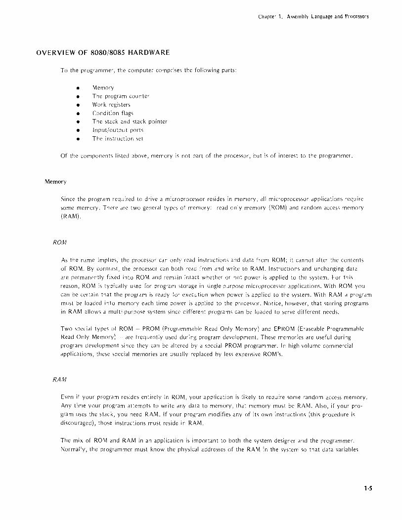
OVERVIEW OF 8080/8085 HARDWARE
To the programmer, the computer comprises the following parts:
• Memory
• The program cou nter
• Work registers
• Condition flags
• The stack and stack pointer
• Input/output ports
• The instruction set
Of the components listed above, memory is not part of the processor, but is of interest to the programmer.
Memory
Since the program required to drive a microprocessor resides in memory. all microprocessor applications require
some memory. There Me two general types of memory: read only memory (ROM) and random access memory
(RAM).
ROM
As the name implies, the processor can only read instructiom and data from ROM; it cannot alter the contents
of ROM. By contrast, the processor can both read from and write to RAM. Instructions and unchanging data
are permanently fixed into ROM and remain intact whether or not power is applied to the system. For this
reason, ROM is typically used for program <.torage in single-purpose microprocessor applications. With ROM you
can be certain that the program is ready for execution when power is applied to the system. With RAM a program
must be loaded into memory each time power is applied to the processor. Notice, however, that storing programs
in RAM allows a multi·purpose system since different programs can be loaded to serve different needs.
Two special types of ROM - PROM (Programmable Read Only Memory) and EPROM (Eraseable Programmable
Read Only Memory) .. are frequently used during program development. These memories are useful during
program development since they can be altered by a special PROM programmer. In high-volume commercial
applications, these special memories are usu.llly replaced by less expensive ROM's.
RAM
Even if your program resides entirely in ROM, your application is likely to require some random access memory.
Any time your program attempts to write any data to memory, that memory must be RAM. Also, if your pro
gram uses the stack, you need RAM. If your program modifies any of its own instructions (this procedure is
discou raged), those instructions must reside in RAM.
The mix of ROM and RAM in an applicaticn is important to both the system designer and the programmer.
Normally, the programmer must know the physical addresses of the RAM in the system so that data variables
1·5
Chapter 1. Assembly Language and Processors
can be assigned within those addresses. However, the relocation feature of this a'isembler allows you to code a
program without concern for the ultimate placement of data and instructions; these program elements can be repositioned after the program has been tested and after the system's memory layout is final. The relocation
feature is fully explained in Chapter 4 of this manual.
Program Counter
1-6
With the program counter, we reach the first of the 8080's internal registers illustrated in Figure 1·3.
NOTE
Except for the difference<, listed at the end of this chapter,
the information in this chapter applies equally to the 8080
dnd the 8085.
The program counter keeps track of the next instruction byte to be fetched from memory (which may be either ROM or RAM). Each time it fetches an instruction bytc from memory, tlcc processor increments thc program counter by one. Therefore, the program counter always indicates the next byte to be fetched. This proccss continues as long a'> program instructions are executed sequentially. To alter the flow of program execution as
with a jump instruction or a call to d ,>ubrouti ne, the processor overwrites the current contents of the program counter with the addrcss of thc new instruction. The next in<,truction fetch occur>; from the new address.
IACCUMULATORI FLAGS
INSTRUCTION DECODER
DATA BUS LATCH
8·bit bidirectional
data bus
ROM
INSTRUCTIONS
CONSTANT DATA
B
D
H
RAM
INSTRUCTIONS
VARIABLE DiHA
STACK
C
E
L
HIGH LOW
[ STACK POINTER
[PROGRAM COUNTER
[ ADDRESS BUS LATCH
INPUT
PORTS
16·bit address bus
OUTPUT
PORTS
Figure 1-3. 8080/8085 I nternal Registers
8080 8085

Chapter 1. Assembly Language and Processors
Work Registers
The 8080 provides an 8-bit accumulator and six other general purpose work registers, as shown in Figure 1-3.
Programs reference these registers by the letters A (for the accumulator), B, C, D, E, H, and L. Thus, the instruction ADD B may be interpreteu as 'add the contents of the B register to the contents of the accumulator.
Some instructions reference a pair of registers as shown in the following:
Symbolic Reference
B D
H
M
PSW
Registers Referenced
Band C D and E
Hand L
Hand L (as a memory reference) A and condition flags (explained
later in this section)
The symbolic reference for a single register is often the same as for a register pair. The instruction to be executed
determines how the processor interprets the reference. For example, ADD B is an 8-bit operation. By contrast
PUSH B (which pushes the contents of the Band C registers onto the stack) is a 16-bit operation.
Notice that the letters Hand M both refer to the Hand L register pair. The choice of which to use depends on
the instruction. Use H when an instruction ae:s upon the Hand L register pair as in INX H (increment the
contents of Hand L by one). Use M when an instruction addresses memory via the Hand L register, as in ADD
M (add the contents of the memory location ';pecified by the Hand L registers to the contents of the accumu
lator) .
The general purpose registers B, C, D, E, H, and L can provide a wide variety of functions such as storing 8-bit
data values, storing intermediate results in arithmetic operations, and storing 16-bit address pointers. Because of the 8080's extensive instruction set, it is usually possible to achieve a common result with any of several different instructions. A simple add to the accumulator, for example, can be accomplished by more than half a dozen different instructions. When possible, it is generally desirable to select a register-to-register instruction such as ADD B. These instructions typically require only one byte of program storage. Also, using data already present in a register eliminates a memory access and thus reduces the time required for the operation.
The accumulator also acts as a general-purpose register, but it has some special capabilities not shared with the other registers. For example, the input/output instructions IN and OUT transfer data only between the accumu
lator and external 1/0 devices. Also, many operations involving the accumulator affect the condition flags as explained in the next section.
Example:
The following figures illustrate the execution of a move instruction. The MOV M,C moves a copy of the contents
of register C to the memory location specified by the Hand L registers. Notice that this location must be in RAM since data is to be written to memory.
1-7

Chapter 1. Assembly language and Processors
1-8
8080 IACCUMULATORI FLAGS I 8085
HIGH LOW
I I I I ! I B C STACK POINTER INSTRUCTION
DECODER I D I
E I I PROGRAM 1 COUNTER i
Y DATA BUS LATCH I H I L I I ADDRESS : BUS LATCH
I • ROM RAM
Figure 1-4. I nstruction Fetch
The processor initiates the instruction fetch by latching the contents of the program counter on the address bus,
and then increments the program counter by one to indicate the address of the next instruction byte. When the memory responds, the instruction is decoded into the series of actions shown in Figure 1-5.
NOTE
The following description of the execution of the MOV M ,C instl·uction is conceptually correct, but
does not aCCOL nt for normal bus control. For details
concerning memory interface, refer to the User's
Manual for your processor.

Chapter 1. Assembly Language and Processors
8080 8085
IACCUMULATORl FLAGS I I B I C I HIGH LOW
INSTRUCTION I I STACK ! POINTER I DECODER
I D I E I I PROGRAM ! COUNTER I DATA BUS LATCH J.- I H I L ADDRESS I BUS LATCH J
+ • ROM RAM
Figure 1-5. Execution of MOV M,C Instruction
To execute the MOV M,C instruction, the processor latches the contents of the C register on the data bus and
the contents of the Hand L registers on the address bus. When the memory accepts the data, the processor
terminates execution of this in5truction and initiates the next instruction fetch.
Internal Work Registers
Certain operations are destructive. For example, a compare is actually a subtract operation; a zero result indicates
that the opreands are equal. Since it is unacceptable to destroy either of the operands, the processor includes
several work registers reserved for its own use. The programmer cannot access these registers. These registers are
used for internal data transfers and for preserving operands in destructive operation5.
Condition Flags
The 8080 provide5 five flip flops used as condition flags. Certain arithmetic and logical instructions alter one or
more of these flags to indicate the result of an operation. Your program can test the setting of four of these
flags (carry, sign, Lero, and parity) using one of the conditional jump, call, or return instruction5. This allows you
to alter the flow of program execution based on the outcome of a previou5 operation. The fifth flag, auxiliJrY
carry, i5 reserved for the usc of the DAA instruction, as will be explained later in thi5 5ection.
It i'i important for the programmer to know which fldgs Jre set by a pdrticular instruction. A5'>urlle, fur ex,lmpic,
that your program is to test the parity of In input byte Jnd then execute one instructiun 'ol'qUl'ncl' il pdrity i,
even, a different instruction set if parity i5 odd. Coding a jPE (jump if parity i5 even) or jPO (jump il parity IS
1-9

Chapter 1. Assembly Language and Processors
1-10
odd) instruction immediately following the IN (input) instruction produces false results since the IN instruction
does not affect the condition flags. The jump executed by your program reflects the outcome of some previous
operation unrelated to the IN instruction. For the operation to work correctly, you must include some instruc·
tion that alters the parity flag after the IN instruction, but before the jump instruction. For example, you can
add zero to the accumulator. This sets the parity flag without altering the data in the accumulator.
In other cases, you will want to set a flag with one instruction, but then have a number of intervening instruc
tions before you use it. In these cases, you must be certain that the intervening instructions do not affect the
desired flag.
The flags set by each instruction are detailed In the individual instruction descriptions in Chapter 3 of thi,
manual.
Carry Flag
NOTE
When a flag is 'set' it is set ON (has the value one);
when a flag is 'reset' it is re,et OFF (ha, the value
zero) .
As its name implies, the carry flag i, commonly u,ed to indicate whether an addition causes a 'carry' into the
next higher order digit. The ca'rry flag is also used as a 'borrow' flag in subtractiom, as expl,lined under 'Two's
Complement Representation of Data' in Chdpter 2 of this manual. The G.my fidg i, <11,0 affected by the logical
AND, OR, and exclusive OR instruction,. These instructions set ON or OFF rarticuldT bits of the dccumulator.
See the description> of the ANA, ANI, ORA, ORI, XRA, and XRI instructioll'i in Charter 3.
The rotate instructions, which move the contents of the accumulator one position to the Ielt or right, tredt the
carry bit as though it were a ninth bit of the ,lccumulator. See the descliption, of the RAL, RAR, RLC, and RRC
instructions in Chapter 3 of this manual.
Example:
Addition of two one-byte number., can produce a carry out of the high·order bit:
Bit Number:
AE=
+74=
7654 3210
1010 1110
0111 0 I 00
00100010 = 22 carry flag =
An addition that causes a carry out of thc high order bit ,ets the carry fI,lg to I; an dddition that duc, not cause
a carry resets the flag to zero.
Sign Flag
As explained under 'Two's Complement Representation of Data' in Chap!er 2, bit 7 of a result in the accumulator
can be interpreted as a sign. Instructions that affect the sign flag set the flag equal to bit 7. A zero in bit 7

Chapter 1. Assembly language and Processors
indicates a positive value; a one indicates a negdtive v,ilue. This value i, duplicated in the sign fldg so thdt
conditional jump, cdll, and return instr"uctiollS can test fm positive and negative value'>.
Zero Flag
Certain instructions set the zero flag to one to indicate that the result in the accumulator contains all zeros.
These instructions. reset the flag to zero if the result in the accumulator is o~her than zero. A result that has a
carry and a zero result also sets the zero bit as shown below:
Parity Flag
1010 0111
+01 01 1001
0000 0000 Carry Flag = 1
Zero Flag = 1
Parity is determined by counting the number of one bits set in the re')ult in the dccumuldtor. In'itructiom lhdt
affect the parity flag set the fldg to one fm even pdrity ,md reset the flag to zero to indicdte odd pdrity.
Auxiliary Carry Flag
The auxiliary carry flag indicates a carry out of bit 3 of the accumulator. You cannot test this flag directly in
your program; it is present to enable the DAA (Decimal Adjust Accumulator) to perform its function.
The auxiliary carry flag and the DAA imtruction allow you to treat the value in the accumulator a'> two 4-bit
binary coded decimal numbers. Thus, the vdlue 0001 1001 i'> equivalent to 19. (If this value is interpreted a'> d
binary number, it has the value 25.) Notice, however, that adding one to this value produces a non·decirn,iI
result:
0001 1001
+0000 0001
000110lD=lA
The DAA instruction converts hexadecimal values such as the A in the preceding example back into binary coded
decimal (BCD) fmmat. The DAA instruction requires the auxiliary carry flag since the BCD tormat make'i it
po'>sible for arithmetic operations to generate a carry from the low-order 4-bit digit into the high·order 4·bit
digit. The DAA performs the following addition to cmrect the preceding eXdmple:
0001 10lD
+00000110
0001 0000
+0001 0000 (auxiliary carry)
0010 0000 = 20
1-11

Chapter 1. Assembly Language and Processors
The auxiliary carry flag is affected by all add, subtract, increment, decrement, compare, and all logical AND,
OR, and exclusive OR instructions. (See the descriptions of these instructions in Chapter 3.) There is some
difference in the handling of the auxiliary carry flag by the logical AND instructions in the 8080 processor and
the 8085 processor. The 8085 logical AN D instructions always set the auxiliary flag ON. The 8080 logical AN D
instructions set the flag to reflect the logical OR of bit 3 of the values involved in the AND operation.
Stack and Stack Pointer
1-12
To understand the purpose and effectiveness of the stack, it is useful to understand the concept of a subroutine.
Assume that your program requires a multiplication routine. (Since the 8080 has no multiply instructions, this can be performed through repetitive addition. For example, 3x4 is equivalent to 3+3+3+3.) Assume further that
your program needs this multiply routine seve:al times. You can recode this routine inline each time it is needed,
but this can use a great deal of memory. Or, you can code a subroutine:
Inline Coding Subroutine
1 1 inline routine CALL
I I inline routine CALL subroutine
I I inline routine CALL
I I The 8080 provides instructions that call and return from a subroutine. When the cdll instruction is executed, the
address of the next instruction (the contents of the program counter) is pushed onto the stack. The contents of
the program counter are replaced by the address of the desired subroutine. At the end of the subroutine, a
return instruction pops that previously-stored address off the stack and puts it back into the program countcr. Program execution then continues as though the subroutine had been coded inline.
The mechanism that makes this possible is, of course, the stack. The stack i~ simply an arCd of random acee,s
memory addressed by the stack pointer. The ',tack pointer is a hdrdware register maintained by the proce,>sor.
However, your program must initialize the stack pointer. This means that your program mu~t load the base
address of the stack into the stack pointer. The base address of the stack is commonly assigned to the highest
available address in RAM. This is because the stack ,expands by decrementing the stack pointer. As items are

Chapter 1. Assembly Language and Processors
added to the stack, it expands into memory locations with lower addresses. As items are removed from the
stack, the stack pointer is incremented back toward its base address. Nonetheless, the most recent item on the stack is known as the 'top of the stack.' Stack is still a most descriptive term because you can always put
something else on top of the stack. In terms of programming, a subroutine can call a subroutine, and so on.
The only limitation to the number of items that can be added to the stack is the amount of RAM available for the stack.
The amount of RAM allocated to the stack is important to the programmer. As you write your program, you
must be certain that the stack will not expand into areas reserved for other data. For most applications, this
means that you must assign data that requires RAM to the lowest RAM addresses available. To be more precise,
you must count up all instructions that add data to the stack. Ultimately, your program should remove from the stack any data it places on the stack. Therefore, for any instruction that adds to the stack, you can sub
tract any intervening instruction that remove, an item from the stack. The most critical factor is the maximum
size of the stack. Notice that you must be sure to remove data your program adds to the stack. Otherwise, any
left-over items on the stack may cause the stack to grow into portions of RAM you intend for other data.
Stack Operations
Stack operations transfer sixteen bits of data between memory and a pair of processor registers. The two basic operations are PUSH, which adds data to the stack, and POP, which removes data from the stack.
A call instruction pushes the contents of the program counter (which contains the address of the next instruction) onto the stack and then transfers control to the desired subroutine by placing its address in the program counter. A return instruction pops sixteen bits off the stack and places them in the program counter. This requires the
programmer to keep track of what is in the ',tack. For example, if you call a subroutine and the subroutine pushes data onto the stack, the subroutine must remove that data before executing a return instruction. Other
wise, the return instruction pops data from the stack and places it in the program counter. The results are
unpredictable, of course, but probably not what you want.
Saving Program Status
It is likely that a subroutine requires the use of one or more of the working registers. However, it is equally likely that the main program has data stored in the registers that it needs when control returns to the main program. As general rule, a subroutine should save the contents of a register before using it and then restore
the contents of that register before returning control to the main program. The subroutine can do this by pushing the contents of the registers onto tre stack and then popping the data back into the registers before
executing a return. The following instruction sequence saves and restores all the working registers. Notice that
the POP instructions must be in the opposite order of the PUSH instructions if the data is to be restored to its
original location.
1-13

Chapter 1. Assembly language and Processors
SUBRTN: PUSH
PUSH
PUSH
PSW
B [)
PUSH H
subroutine coding
POP H
POP [)
POP B
POP PSW
RETURN
The letters B, D, and H refer to the Band C, D and E, and Hand L register pairs, respectively. PSW refers to
the program status word. The program status word is a 16-bit word comprising the contents of the accumulator
and the five conpition flags. (PUSH PSW adds three bits of filler to expand the condition flags into a full
byte; POP PSW strips out these filler bits.)
Input/Output Ports
1-14
The 256 input/output ports provide communication with the outside world of peripheral devices. The IN and
OUT instructions initiate data transfers.
The IN instruction latches the number of the de,ired port onto the address bus. As soon as a byte of data is
returned to the data bu,> latch, it is transferred into the accumulator.
The OUT instruction latches the number of the desired port onto the address bus and latches the data in the
accumulator onto the data bus.
The specified port number is duplicated on the address bus. Thus, the instruction IN 5 latches the bit configura
tion 00000101 00000101 onto the add res', bus.
Notice that the IN and OUT instructions simply initiate a data transfer. It is the responsibility of the peripheral
device to detect tha tit has been addressed. \Jo tice al so that it is possible to ded ica te any nu m ber of ports to
the same peripheral device. You might use a number of ports a, control signals, for example.
Because input and output are almost totally application dependent, a discussion of design techniques is beyond
the scope of this manual.
For additional hardware information, refer to the 8080 or 8085 Microcomputer Systems User's Manual.
For related programming information, see the descriptions of the IN, OUT, DI, EI, RST, and RIM and SIM
instructions in Chapter 3 of this manual. (The RIM and SIM instructiom apply only to the 8085.)

Chapter 1. Assembly Language and Processors
Instruction Set
The 8080 incorporates a powerful array of instructions. This section provides a general overview of the instruc
tion set. The detailed operation of each instruction is described in Chapter 3 of this manual.
Addressing Modes
Instructions can be categorized according to their method of addressing the hardware registers and/or memory.
Implied Addressing. The addressing mode of certain instructions is implied by the instruction's function. For
example, the STC (set carry flag) instruction deals only with the carry flag; the DAA (decimal adjust accumu
lator) instruction deals with the accumulator.
Register Addressing. Quite a large set of instructions call for register addre<;sing. With these instructions, you
must specify one of the registers A through E, H or L as well as the operation code. With these instructions,
the accumulator is implied as a second operand. For example, the instruction CMP E may be interpreted as
'compare the contents of the E register with the contents of the accumulator.'
Most of the instructions that use register addressing deal with 8-bit values. However, a few of these instructions
deal with 16-bit register pairs. For example, the PCHL instruction exchanges the contents of the program counter
with the contents of the Hand L registers.
Immediate Addressing. Instructions that use immediate addressing have data assembled as a part of the instruction
itself. For example, the instruction CPI 'C' may be interpreted as 'compare the contents of the accumulator with
the letter c.' When assembled, this instruction has the hexadecimal value FE43. Hexadecimal 43 is the internal
representation for the letter C. When this instruction is executed, the processor fetches the first instruction byte
and determines that it must fetch one more :lyte. The processor fetches the next byte into one of its internal
registers and then performs the compare ope'ation.
Notice that the names of the immediate instructions indicate that they use immediate data. Thus, the name of an
add instruction is ADD; the name of an add immediate instruction is AD!.
All but two of the immediate instructions use the accumulator as an implied operand, as in the CPI instruction
shown previously. The MVI (move immediat'~) instruction can move its immediate data to any of the working
registers, i ncl udi ng the accu mulator, or to m<~mory. Th us, the instruction MVI D ,OF FH moves the hexadecimal
value FF to the D register.
The LXI instruction (load register pair immediate) is even more unu,ual in that its immediate data is a 16-bit
value. This instruction is commonly used to load addresses into a register pair. As mentioned previously, your program must initialize the stack pointer; LXI i, the instruction most commonly used for this purpose. For ex
ample, the instruction LXI SP,30FFH loads the ,tack pointer with the hexadecimal value 30FF.
Direct Addressing. Jump instructions include a 16-bit address as part of the instruction. For example, the
instruction J MP 1000H causes a jump to the hexadecimal address 1000 by replacing the current contents of the
program coun ter with the new val ue 1000.
1-15
Chapter T. Assembly Language and Processors
Instructions that include a direct address require three bytes of storage: one for the instruction code, and two
for the 16·bit address.
Register Indirect Addressing. Register indirect instructions reference memory via a register pair. Thus, the
instruction MOV M,C moves the contents of the C register into the memory address stored in the Hand L
register pair. The instruction LDAX B load, the accumulator with the byte of data specified by the address
in the Band C register pair.
Combined Addressing Modes. Some instructions use a combination of addressing modes. A CALL instruction,
for example, combines direct addressing and register indirect addressing. The direct address in a CALL instruction specifies the address of the desired subroutine; the register indirect address is the stack pointer. The CALL instruction pushes the current contents of the program counter into the memory location specified by the stack
pointer.
Timing Effects of Addressing Modes. Addressing modes affect both the amount of time required for executing
an instruction and the amount of memory required for its storage. For example, instructions that use implied or register addressing execute very quickly since they deal directly with the processor hardware or with data already
present in hardware registers. More important, however, is that the entire instruction can be fetched with a single memory access. The number of memory accesses required is the single greatest factor in determining execution timing. More memory accesses require more execution time. A CALL instruction, for example, requires
five memory accesses: three to access the entire instruction, and two more to push the contents of the program
counter onto the stack.
The processor can access memory once during each processor cycle. Each cycle comprises a variable number of
states. (The individual instruction descriptions in Chapter 3 specify the number of cycles and states required for
each instruction.) The length of a state depends on the clock frequency specified for your system, and may
range from 480 nanoseconds to 2 microseconds. Thus, the timing of a four state instruction may range from
1.920 microseconds through 8 microseconds. (The 8085 has a maximum clock frequency of 320 nanoseconds
and therefore can execute instructions aboJt 50% faster- than the 8080.)
Instruction Naming Conventions
The mnemonics assigned to the instructions are ~esigned to indicate the function of the instruction. The instruc
tions fall into the following functional categories:
Data Transfer Group. The data transfer instructions move data between registers or between memory and registers.
MOV MVI
LOA
STA LHLD SHLD
Move Move Immediate Load Accumulator Directly from Memory
Store Accumulator Directly in Memory Load Hand L Registers Directly from Memory Store Hand L Registers Directly in Memory
ALL MNEMONICS © 7974, 7975, 7976, 7977 INTEL CORPORA nON
1·16

Chapter 1. Assembly Language and Processors
An 'X' in the name of a data transfer instruction implies that it deals with a register pair:
LXI
LDAX
STAX XCHG XTHL
Load Register Pair with Immediate data
Load ACCL.,mulator from Address in Register Pair Store Accumulator in Address in Register Pair
Exchange Hand L with D and E Exchange Top of Stack with Hand L
Arithmetic Group. The arithmetic instructions add, suhtract, increment, or decrement data in registers or
memory.
ADD
ADI
ADC
ACI
SUB SUI
SBB SBI
INR
DCR
INX
DCX
DAD
Add to Accumulator
Add Immediate Data to Accumulator
Add to Accumulator U~ing Carry Flag
Add Immediate Data to Accumulator Using Carry Flag
Subtract from Accumulator
Subtract Immediate Data from Accumulator
Subtract from Accumulator Using Borrow (Carry) Flag Subtract Immediate from Accumulator Using Borrow
Increment Specified Byte by One
Decrement Specified Byte by One
Increment Register Pair by One
Decrement Register Pair by One
Double Register Add: Add Contents of Register
Pair to Hand L Register Pair
Logical Group. This group performs logical (Boolean) operations on data in registers and memory and on
condition flags.
The logical AND, OR, and Exclusive OR instructions enable you to set specific bits in the accumulator ON or OFF.
ANA
ANI
ORA
ORI XRA
XRI
Logical AND with Accumulator
Logical Ar-JD with Accumulator Using Immediate Data
Logical OR with Accumulator
Logical OR with Accumulator Using Immediate Data
Exclusive Logical OR with Accumulator
Exclusive OR Using Immediate Data
The compare instructions compare the contents of an 8-bit value with the contents of the accumulator:
CMP
CPI
Compare
Compare Using Immediate Data
ALL MNEMONICS © 7974, 7975, 7976, 7977 INTEL CORPORATION
1-17

CllJpCer 1. Assembly Language and Processors
The rotate instrucliom '>hift the contents of the accumulator one bit po,>ition to the lett or right:
RLC
RRC
RAL
RAR
Rotate Accumulator Left
Rotate Accumulator Right
Rotate Left Through Carry
Rotate Rght Through Carry
Complement and carry flag instructiolls:
CMA
CMC
STC
Complement Accumulator
Complement Carry Flag
Set Carry Flag
BrcJl7ch Group. The branching instruction,> alter normal sequential pr"ogram flow, either unconditionally or
conditionally. The unconditional branching instructions arc dS follows:
jMP
CALL
RET
jump
Call
Ret urn
Conditional brdnching imtructions examine the ,tatus of one of four" condition flags to determine whether the
,>pecified br,lflch i, to be executed. The conditiolls that may be specified are as follows:
NZ Not Zero (Z = 0)
Z Zero (Z " 1)
NC No CarTY (C = 0)
C Carry (C = 1)
PO Parity Oeld (P = 0)
PE Parity Evell (P = 1) P Pill'> (S = O)
M Minus (S = I)
T;lu,>, the conciitiunal branching in'Multiolls are specified as follows:
Two other"
Jumps Calls Returns
jC CC RC (Cmy)
jNC CNC RNC (No Carry) jZ CZ RZ (Zero)
JNZ CNZ RNZ (Not Zero) jP CP RP (Plus) jM CM RM (Minus) jPE CPE RPE (Parity Even)
jPO CPO RPO (Parity Odd)
instructions Cdn effect a branch ay replacing the contents of the program counter:
PCHL
RST
Move Hmd L to Pmgram Counter"
Special Rer,tart InstructJon Used with Interrupts
ALL MNEMONICS © 7974, 7975, 7976, 7977 INTEL CORPORA TlON
1-18

Chapter 1. Assembly Language and Processors
Stack, I/O, and Machine Control Instructions. The following instructions affect the stack and/or stack pointer:
PUSH
POP
XTHL
SPHL
The [/0 imtructiom Me dS follows:
IN
OUT
Push Twu Bytes of Data onto the Stack
Pop Two Bytes of Data off the Stack
Exch'lIlge Top of Stack with Hand L
Move content'> of Hand L to Stack Pointer
Initiate Input Operation
Initiate Output Operation
The machine contlo[ imtructiom arc as follows:
EI
DI
HLT
NOP
Enab[e I nterrupt System
Disable Interrupt System
Ha[t
No Operdtion
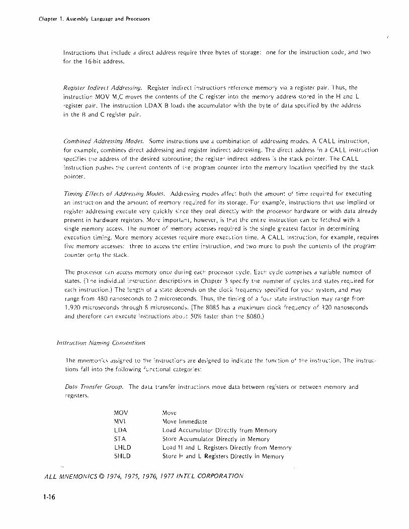
HARDWARE/INSTRUCTION SUMMARY
The following illustrations gl'aphic,!I[y summarize the instruction '>et by showing the hardware acted upon by
,>pecific in'>truction'>. The type of operanu al[owed for each instruction is inuicateu through the use of a code.
When no (oue i'> given, the instruction uoes not a[low operands.
Code Meaning
REGM S The operand may specify one of the S-bit registers A,B,C,D,E,H, or L or M
(a memo -y reference via the 16-bit address in the Hand L registers). The
MOV instruction, which calls for two operands, can specify M for only one
of it<, operands.
Accumulator Instructions
Designates S-bit immediate operand.
Designates a 16-bit audress.
De,>ignates an 8-bit port number.
De,>ignatc'> a 16-bit register pair (B&C,D&E,H&L, or SP).
Designate,> a 16-bit immediate operand.
The fo[lowing illustration shows the instructions that can affect the accumulator. The instructions listed above
the accumu[dtor a[1 act on the data in the accumulator, and a[[ except CMA (complement accumulator) affect
one or mmc of the conditioll flag'>. The instructions listed below the accumulator move data into or out of the
accLlmu[dtor, but do not affect conditioll flags. The STC (set carry) and CMC (comp[ement carry) instructions
arc also shown here.
ALL MNEMONICS © 7974, 7975, 7976, 7977 INTEL CORPORA TlON
1·19
Chap[er 1. As~embly Language and Processors
ADD
ADC
SUB
SBB ANA REGM S
XRA
ORA
CMP
RLC RAL
RAR CMA
INR} OCR
ACCUMULATOR
B
ADI
ACI
SUI
SBI
ANI Os XRI
ORI
CPI RRC
DAA
R.EGMS
FLAGS
C
E MOV REGM S.' REG MSIL. ___ D ___ L-_. ___ --'
H L
LDAX} STAX BC,DE
MEMORY
LOA} STA A'6
STACK
STC CMC HIGH LOW
STACK POINTER
I PROGRAM COUNTER I
I I IN Ps OUT Ps INPUT
PORTS
OUTPUT
PORTS
ALL MNEMONICS © 1974, 1975, 1976, 1977 INTEL CCRl'n.R.A TlON
1-20

Chapter 1. Assembly language and Processors
Register Pair (Word) Instructions
The following instructions all deal with 16-bit words. Except for DAD (which adds thecontents of the B&C or
D&E register pair to H&L), none of these instructions affect the condition flags. DAD affects only the carry
flag.
IACCUMULATORI FLAGS ] INX)
1 B C ] DCX
DAD
I D E ~-XCHG I H L .. -
I-- XTHL--
LHLD
SHLD
~I-----, MEMORY
HIGH
REG'6 SPHL -I STACK
PCHL ... 1 PROGRAM !
STACK ... PUSH ) POP B,D,H,PSW
ALL MNEMONICS © 7974, 7975, 7976, 7977 INTEL CORPORA nON
LOW
POINTER
COUNTER I
1-21

Chapter 1. Assembly Language and Processor,
Branching Instructions
The following instructions can alter the con:ents of the program counter, thereby altering the normal sequential
execution flow. Jump instructions affect only the program counter. Call and Return instructions affect the program counter, stack pointer, and stack.
IACCUMULATORI FLAGS
B C
D E
H L
MEMORY
STACK
I HIGH LOW
I STACK POINTER
I JPCHL~RAM COUNTER RST
~ JMP CALL RET
~~ ~~~) A ~~ ~~~) A :~ :~~} A JP JM 16 CP CM 16 RP RM 16
J PE J PO CPE CPO RPE RPO
CONTROL INSTRUCTIONS
RST NOP HLT EI DI
SIM\ RIMJ 8085 only
ALL MNEMONICS© 7974,7975,7976, 7977 INTEL CORPORATION
1-22

Chapter 1. Assembly language and Processors
Instruction Set Guide
The following is a summary of the instruction set:
ADD ADC ACI
SUB SUI
ADll SBB REGM g ~~l f D8 ANA
XRA )(RI
ORA ORI CMP CPI
RLC RAL RRC RAR CMA DAA
INR} DCR REGMg
~ACCUMULATORI FLAGS
MOY REGMg,REGMgl B I C
I I D I LXI REG 16,D 16
E
H L
]STC CMC
INX} JDCX REG 16 SPHL DAD I
~ PCHL
k XCHG I JMP
HIGH LOW
STACK
RST
CALL RET
JC JZ JP JPE
JNZ A JNC} JM 16
CZ CNZ A CC CNC}
CP CM 16 RZ RNZ A RC RNC}
RP RM 16
/ A ,
LDAX} BC,DE STAX
LDA} STA A
16
MYI Dg
MOY REGMg,REGM g
CODE
REGM g
LHLD} STHD A16
MEMORY [
INPUT PORTS
JPO
I OUT Pg
OUTPUT PORTS
f---STACK--- ... __ ~~~H} B,D,H,PSW
MEANING
CPE CPO RPE RPO
CONTROL INSTRUCTIONS
RST NOP HLT EI DI
SIM} gOg5 ONLY RIM
The opcrand may specify one of thc g-bit registers A,B,C,D,E,H, or L or M (a memory refercnce via thc 16-bit addrcss in the Hand L registers). The MOY instruction, which calls for two operands, can ~pecify M for only one of its operands. Designates g·bit immcdiatc operand. Dcsigna tes a 16-bit address. Dcsignates an g-bit port numbcr. Dcsignates a 16-bit rcgisTer pair (B&C,D&E.H&L,or SP).
Dcsignatcs a 16 -bit immediatE' opcrand.
ALL MNEMONICS © 7974, 7975, 7976, 7977 INTEL CORPORA TlON
1-23

Chapter 1. Assembly Language and Processors
8085 PROCESSOR DIFFERENCES
The differences between the 8080 proces'>or and the 8085 processor will be mme obviou,> to the system designer
than to the programmer. Except for two additional instructions, the 8085 in'>truction set is identical to and fully
compatihle with the 8080 instruction '>et. Mo,;t programs written for the 8080 should operate on the 8085 with
out modification. The only programs that may require changes arc those with critical timing routines; the higher
system <;peed of the 8085 may alter the time values of ,>uch routines.
A partial listing of 8085 de,ign fcature,> includes the following:
• A ,ingll' 5 volt power ,uppl),.
• Execution speed, ap.PI-oximately 50% fa,ter than the 8080.
• Incorporation in the proce'><;()1 of the featurc<; of the 8224 Clock Geneldtor and Driver and the
8228 Sy,tem Controller and Bu'> Drivel-.
• A non·maskable TRAP interrupt fOl" h,mdling serious problems such as power failul-e'>.
• Three separately maskablc interrupt<, that gcnel-ate internal RST imtructions.
• Input/output line, for serial data transfer.
Programming for the 8085
1-24
For the programmer, the new featLlI-es of the 8085 all' summ,niLed in the two new instructions SIM and RIM.
These instructions differ from 'the 8080 instr JctioJl', in that each has multiple function'>. The SIM in<,lruction
sets the interrupt mask and/O! writes out a bit of serial delta. The proglammCl" must place the desiled interrupt
mask and/or scrial output in the dccumulatClI prior to execution of the SIM instruction. The RIM imtruction
reads a bit of serial data if one is present a III I the interrupt ma<;k into the accumuLitor. Details of these instruc
tions arc covered in Chapter 3.
Despite the new interl-upt features of the 80B5, programming for intenupts i., little ch,mged. Notice, however, that
8085 hardware interrupt RESTART addre,<;e, fall hetween the existing 8080 REST ART addresses. Therefore,
only four bytes arc available for certain RST instruction'>. AI<;o, the TRAP interrupt input i, non-maskable and
cannot be di,ahled. If your application usc, his input, he certdin to plw:ide ,iI) intclTupt routine for it.
The interrupt<; have the following priority:
TRAP
RSn.5
RST6.5
RST5.5
INTR
higheq
lowe'>t
When more than one interrupt is pending, the processor always recognizes the higher priority interrupt first.
These priorities apply only to the ,>equence in which interrupts arc recogni/ed. Program routines that service
interrupts have no special priority. Thus, an RST5.5 interrupt can interl-upt the service routine for an RST7.5
interrupt. If you want to protect a service routine from interruption, either disable the interrupt system (DI
instruction)' or mask out other potential interrupts (SIM instruction).

Chapter 1. Assembly Language and Processors
Conditional Instructions
Execution of conditional instructions on the 8085 differs from the 8080. The 8080 fetches all three instruction
bytes whether or not the condition is satisfied. The 8085 evaluates the condition while it fetches the second instruction byte. If the specified condition is not satisfied, the 8085 skips over the third instruction byte and
immediately fetches the next instruction. Skipping the unnecessary byte allows for faster execution.
1-25


2. ASSEMBLY LANGUAGE CONCEPTS
INTRODUCTION
Just as the English languJge has its rules of grammar, assembly IJngUJge has certain coding rule'>. The source line
is the assembly IJnguage equivalent of a sentence.
Thi,> Jssembler recognize'> three types of source lines: instructions, directive'>, and controls. This manual describes
instructions and directive'>. Control'> <ire described in the operJtor's mJnual for your version of the Jssembler.
This chapter describes the generdl rules for coding source lines. Specific instructions (see Chapter 3) and
directives (see ChJpters 4 and 5) may have >pecific coding rules. Even '>0, the coding of such instructions and
directives must conform to the general rule'. in this chapter.
SOURCE LINE FORMAT
Assembly language instructions and a'>sembler directives may comist of up to four fields, as follows:
{Label:} Name
Opcode Operand ;Comment
The field,> may be ~eparated by any number· of blanks, but must be separated by at least one delimiter. Each
instruction and directive must be entered on a si:rgle line terminated by a carriage return and a line feed. No
continuation lines arc poS'>ible, but you may have line'> consisting entirely of comments.
Character Set
The following characters are legal in a'>Sembly language source statements:
• The letter·s of the alphabet, A through Z. Both upper- and lower-case letter, <ire allowed. Internally,
the assembler treats all letters as though they were upper-case, but the characters arc printed exactly
as they were input in the assembly li·,ting.
• The digits 0 through 9.
• The following special characters:
2-1

Chapter 2. Assembly Language Concepts
2·2
Character
+
*
&
$ @
< > %
blank
CR
FF
HT
Meaning
Plus sign
Minus sign
Asterisk
Slash
Comma
Left pdrenthesis
Right parenthesis
Single quote
Ampersand
Colon
Dolldr sign
Commercidl 'dt' sign
Question mdrk
Eq ual sign
Less than sign
Greater than sign
Percent sign
Exclamation point Blank or SPdce
Semicolon
Period
Carridge return
Form feed
Horizontal tdb
• In addition, any ASCII chdrdcter mdY appear in d qring enclo'>ed in ~ingle quotes or in d comment.
Delimiters
Certain chdracters have specidl meaning to the dssembler in that they function as delimiters. Delimiter~ define
the end of a source statement, a field, or d component of a field. The following list defines the delimiters
recognized by the assembler. Notice that many delimiters dre related to the macro feature explained in Chapter
5. Delimiters used for macros are shown her2 so that you will not dccidentdlly use a delimiter improperly.
Refer to Chapter 5 for a description of macro'>.
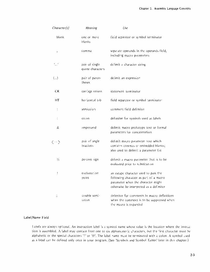
Character(s)
blank
( ... )
CR
HT
&
< ... >
%
Label/Name Field
Meaning
one or more
blan ks
comma
pair of single
quote characters
pair of paren
theses
carriage return
horizontal tab
semicolon
colon
ampers(lrid
pair of angle
brackets
per-cent ',ign
excldmation
point
double semi
colon
Chapter 2. Assembly Language Concepts
Use
field separator or symbol terminator
separate operands in the operands field,
including macro pardmeters
delimit a character string
delimit an expression
statement terminator
field separator or symbol terminator
comment field delimiter
delimiter for ,ymbols used dS labels
delimit macro prototype text or formdl
pardmeters for concdtenation
delimit macro pJrdmeter text which
contains commdS or embedded blank,;
also used to delimit a pJrameter list
delimit a macro pdrameter thdt is to be
evaludted prior to sub,ti.tution
an escape character used to pass the
following chdrdcter dS pdrt of d mdcro
parameter when the character might
otherwise be interpreted as d delimiter
delimiter for comments in macro definitions
when the comment is to be suppressed when
the macro is expanded
Labels arc alwdys optional. An instruction label is d symbol name whose value is the locdtion where the imtruc
tion is assembled. A label may contain from one to six alphdnumeric chdracters, but the first chJrdcter mu,t be
alphabetic or the specidl characters '7' or '@'. The label name must be terminated with a colon. A symbol used
as a label can be defined only once in your program. (See 'Symbols and Symbol Tables' later in this chapter.)
2-3

Chapter 2. Assembly Language Concepts
Alphanumeric characters include the letters of the alphabet, the question mark character, and the decimal
digits 0 through 9.
A name is required for the SET, EQU, and MACRO directives. Names follow the same coding rules as labels,
except that they must be terminated with a blank rather than a colon. The label/name field must be empty for
the LOCAL and EN OM directives.
Opcode Field
This required field contains the mnemonic operation code for the 8080/8085 instruction or assembler directive
to be perfor med.
Operand Field
The operand field identifies the data to be operated on by the specified opcode. Some instructions require no
operands. Others require one or two operands. As a general rule, when two operands are required (as in data
transfer and arithmetic operations), the fir,t operand identifies the destination (or target) of the operation's
result, and the second operand specifies the ',ource data.
Examples:
MOV
MVI
A,C A,'B'
;MOVE CONTENTS OF REC; C TO ACCUMULATOR
;MOVE B TO ACCUMULATOR
Comment Field
The optional comment field may contain an'! information you deem useful for annotating your program. The
only coding requirement for this field is that it be preceded by a semicolon. Because the ,emicolon i, a delimiter,
there is no need to separate the comment from the previous field with one or more space,>. However, spaces are
commonly used to improve the readability of the comment. Although comments arc alway, optional, you should
usc them liberally since it is easier to debug and maintain a well documented program.
CODING OPERAND FIELD INFORMATION
2-4
There are four types of information (a through d in the following list) that may be requested as items in the
operand field; the information may be specified in nine ways, each of which is described below.

Chapter 2. Assembly Language Concepts
OPERAND FIELD INFORMATION
Information required Ways of specifying
(a) Register (1) Hexadecimal Data (b) Register Pair (2) Decimal Data
(c) Immediate Data (3) Octal Data (d) 16-bit Address (4) Binary Data
(5) Location Counter ($) (6) ASCII Constant (7) Labels assigned values
(8) Labels of instructions or data
(9) Expressions
Hexadecimal Data. Each hexadecimal number mu'>l begin with a numeric digit (0 through 9) and must be
followed by the letter H.
Label Opcode Operand Comment
HERE: MVI C,OBAH ;LOAD REG C WITH HEX BA
Decima! Data. Each decimal number may be identified by the letter D immediately after its last digit or may
stand alone. Any number not specifically identified as hexadecimal, octal, or binary is assumed to be decimal. Thus, the following statements are equivalent:
Label
ABC:
Opcode
MVI
MVI
Operand
E,15
E,15D
Comment
;LOAD E WITH 15 DECIMAL
Octo! Data. Each octal number must be followed by the letter 0 or the letter O.
Lobe! Opcode Operand
LABEL: MVI A,720
Binary Data. Each binary number must be followed by the letter B.
Lobe! Opcode Operand
NOW: MVI D,11110110B
Comment
;LOAD OCTAL 72 INTO ACCUM
Comment
;LOAD REGISTER D
;WITH OF6H
2-5

Chapter 2. Assembly Language Concepts
2-6
Location Counter. The $ character refers to the current location counter. The location counter contains the
address where the current instruction or data statement will be assembled.
Label Opcode
GO: )MP
Operand
$+6
Comment
;) UMP TO ADDRESS 6 BYTES BEYOND
;THE FIRST BYTE OF THIS
;INSTRUCTION
ASCII Constant. One or more ASCII characters enclosed in singte quotes define an ASCII constant. Two successive single quotes must be used to represent one single quote within an ASCII constant.
Label Opcode
MVI
DATE: DB
Operand
F '*' - ,
Comment
;LOAD E REG WITH 8-BIT ASCII
;REPRESENTATION OF * 'TODAY"S DATE'
Labels Assigned Values. The SET dnd EQU directives can a,sign values to label'.. In the following example,
assume that VALUE has been assigned the \alue 9FH; the two stdtement, Me equivalent:
Label
A1:
A2:
Opcode
MVI
MVI
Operand
D,9FH
D,VALUE
Comment
Labels of Instruction or Data. The label as<igned to an instruction or a data definition ha'> as its vdlue the
address of the first byte of the instruction or data. Instructions elsewhel'e in the progrdm can refer to this
address by its symbolic label name.
Label Opcode Operand Comments
HERE: )MP THERE ;)UMP TO INSTRUCTION AT THERE
THERE: MVI D,9FH
Expressions. All of the operand types discllssed previously can be comlJined by operators to form an expression. In fact, the example given for the location counter ($+6) i, dn expression that combines the location counter with the decimal number 6.
Becduse the rule, for coding expressions are rather extensive, further discu"ion of expressions is deferred until later in this chapter.

Chapter 2. Assembly Language Concepts
Instructions as Operands. One operand type was intentionally omitted from the list of operand field infor
mation: Instructioll'> enclosed in parentheses may appear in the operands field. The operand has the value of
the left-most byte of the assembled instruction.
Label Opcode Operand
INS: DB (ADD C)
The statement above defines a byte with the value 81 H (the object code for an ADD C instruction). Such
coding is typically used where the object program modifies itself during execution, a technique that is strongly
discouraged.
Register-Type Operands. Only instructions that allow registers as operands may have register-type operands.
Expressions containing register-type operands are flagged as errors. Thus, an instruction like
IMP A
i, flagged a, an illegal use of J register.
The only assemblC'r directives that may contain register-type operands arc EQU, SET, and actual parameters in
macro calls. Registers can be a,signed alternate names only by EQU or SET.
TWO'S COMPLEMENT REPRESENTATION OF DATA
Any 8-bit byte contains one of the 256 possible combinations of zeros and ones. Any particular combination may
be interpreted in J number of ways. For example, the code 1 FH may be interpreted as an instruction (Rotate
Accumuiator Right Through Carr'y), as the hexadecimal value 1 F, the decimal value 31, or simply the bit
pattern 00011111.
Arithmetic instructions as,ume that the data byte, upon which they operate arc in the 'two's complement' format. To understand why, let u, first examine two examples of decimal arithmetic:
35
-12
23
35
+88
123
Notice that the results of the two examples are equal if we disregard the carry out of the high order position in
the second example. The second example illustrates subtraction performed by adding the ten's complement of
the subtrahend (the bottom number) to the minuend (the top number). To form the ten's complement of a
decimal number, first subtract each digit of the subtrahend from 9 to form the nine's complement; then add one
to the resul t to form the ten's complement. Thus-, 99--12=87; 87+ 1 =88, the ten's complement of 12.
The ability to perform subtraction with a form of addition is a great advantage in a computer since fewer cir-
cuit, are required. Also, arithmetic operations within the computer are binary, which simplifies matters even more.
2·7

Chapter 2. Assembly Language Concepts
2·8
The processor forms the two's complement of a binary value simply by reversing the value of each bit and then adding one to the result. Any carry out of the high order b!t is ignored when the complement is formed. Thu" the subtraction shown previously is pel'formed as follows:
35 = 0010 0011 -12 = 0000 11 00 = 1111 0011
23 +
1111 01 00
0010 0011 +1111 01 00
1 0001 0111 = 23
Again, by disregarding the carry out of the high order position, the subtraction is performed through a form of addition. However, if this operation were performed by the 8080 or the 8085, the carry flag would be set OFF
at the end of the subtraction. This is because the processors complement the carry flag at the end of a subtract
operation so that it can be u,ed as a 'borrow' flag in multibyte subtractions. In the example shown, no borrow is required, so the carry flag is set OFF. By contrast, the carry flag is set ON if we subtract 35 from 12:
1 2 = 0000 11 00
-35 = 0010 0011 11 01 11 00
0000 1100
+1101 1101
+ 11101001=2330r105
1 1 01 1 1 01
In this case, the absence of a carry indicates that a borrow is required from the next higher order byte, if any. Therefore, the processor sets the carry flag ON. Notice also that the result is stored in a complemented form. If you want to interpret this result as a decimal value, you must again form its two's complement:
1110 1001 =0 0001 0110 ,. 1
0001 0111 = 23
Two's complement number, may also be sig:led. When a byte is interpreted as a signed two's complement number, the high order bit indicates the sign. A zero in this bit indicate, a positive number, a one d negative number. The seven low order bits pmvide the magnitude .)f the number. Thus, 0111 1111 equal, + 127.
At the beginning of this description of two\ complement arithmetic, it was stated that any 8·bit byte may con·
tain one of the 256 possible combinations of zews and ones. It must also be stated that the proper interpretation of data is a progrdmming responsibility.
As an example, consider the compJre instru:tion. The compare logic cOIhiders only the LIW bit values of the
items being compared. Therefore, a negative two's complement number alway, compMes higher than a positive
number, because the negative number's high order bit is always ON. A, a result, the meanings of the flags set by
the compare instruction Me reversed. Your program must account for this condition.

Chapter 2. Assembly Language Concepts
SYMBOLS AND SYMBOL TABLES
Symbolic Addressing
If you have never done symbolic programming before, the following analogy may help clarify the distinction
between a symbolic and an ab,olute address.
The locations in program memory can be compared to a cluster of post office boxes. Suppose Richard Roe
rents box 500 for two months. He can then ask for his letters by saying 'Give me the mail in box 500,' or
'Give me the mail for Roe.' If Donald Smith late( rents box 500, he too can ask for his mail by either box
number 500 or by his name. The content of the post office box can be accessed by a fixed, absolute address
(500) or by a symbolic, variable name. The postal clerk correlates the symbolic names and their absolute values
in his log book. The assembler performs the same function, keeping track of symbols and their values in a
symbol table. Note that you do not have to assign values to symbolic addresses. The assembler references its
location counter during the assembly proce5S to calculate these addresses for you. (The location counter does
for the as~embler what the program counter does for the microcomputer. It tells the assembler where the next
instruction or operand is to be placed in memory.)
Symhol Characteristics
A symbol can contain one to six alphabetic (A-Z) or numeric (0-9) characters (with the first character alphabetic)
or the '>pecial character '?' or '@'. A dollar ';ign can be used as a symbol to denote the value currently in the
location counter. For eXample, the command
JMP $+6
forces a jump to the imtruction residing six memory locations higher than the JMP instruction. Symbols of the
form '??nnn' are generated by the as>;embler to uniquely name symbols local to macros.
The a'>sembler regdrds symbols as having the following attribute>;: re'>erved or user-defined; global or limited;
permanent or reddinable; <lnd absolute or rclocatable.
Reserved, User-Defined, and Assembler-Generafed Symbols
Reserved symbol<, are those that already have special meaning to the assembler and therefore cannot appear as
user-defined '>ymbols. The mnemonic names for machine instructions and the assembler directives are all reserved
symbol.,.
2-9

Chapter 2. Assembly language Concepts
2-10
The following instruction operand symbols arc also reserved:
Symbol
$
A
B
C
D
E H
L
SP
PSW
M
Meaning
Location counter reference
Accumulator register
Register B or register pair Band C
Register C
Register D or register pair D and E
Register E
Register H or register pair Hand L
Register L Stack pointer register
STACK MEMORY
Program status word (Contents of A and status flags) Memory reference code using address in Hand L
Special relocatability feature Special relocatability feature
NOTE
The STACK Jnd MEMORY symbols arc fully discussed in Chapter 4.
User-defined symbols arc symbols you create to reference instruction and data addresses. These symbols arc defined when they appear in the label field (If an instruction or in the name field of EQU, SET, or MACRO directives (see Chapters 4 and 5).
Assembler·generated ~ymbols arc created by the assembler to replace usel'-defined symbols whose scope is limited
to a macro definition.
Global and Limited Symbols
Most symbols arc global. This means that they have meaning thl"Oughout your program. Assume, for example,
that you assign the symbolic name RTN to a routine. You may then code a jump or a call to RTN from any
point in your program. If you assign the symbolic name RTN to a second routine, an error results since you
have given multiple definitions to the same name.
Certain symbol~ have meaning only within a macro definition or within a call to that macro; these symbols are 'local' to the macro. Macros require local ~ymbols because the same macro may be used many times in the
program. If the symbolic name~ within mJcro~ were global, each use of the macro (except the first) would cause multiple definitions for those symbolic names.
See Chapter 5 for additional information ab,)ut macros.

Chapter 2. Assembly Language Concepts
Permanent and Redefl'nable Symbols
Most symbol~ drc permanent since their vdlue cannot chdnge during the a~sembly operation. Only symbols
defined with the SET and MACRO assembler directives arc redefinable.
Absolute and Relocatable Symbols
An important attribute of symbols with this dssembler is that of relocatability. Relocatable programs arc
assembled relative to memory location zero. These progrdms arc Idter relocated to some other set of memory
locations. Symbols with addresses that change during relocation arc relocatdble symbols. Symbols with
addres,e, that do not change durillg relocltion are absolute symbols. Thi,> distinction becomes important when
the symbols arc used within expressions, a'> will be explained Idter.
External and public symbol, arc '>pecial types of relocatdble ,ymbols. These ,ymbols <Ire required to establish
program lillkdge when sever,iI relocatdble program module, arc boulld together to form a single application
program. ExternJI symbols arc those used in the current program module, but defined in ,lIlother module.
Such symbols must appear in dn EXTRN ';tatelTlellt, or the assembler will fidg them as undefined.
Conversely, PUBLIC <,ymbols arc defined in thc current progr·am module, but mdY be dccessed by other
module,>. The dCldresses for the,c ,>ymbols dre resolved·when the module, Me boulld together.
Absolute and r·clocatable ,ymbols mdY both appear in d relocatable module. References to any of the assembler
defined register) A through E, H dnd L, PSW, SP, and M arc absolute since they refer to hardware locations.
But these refercllccs arc valid in allY module.
ASSEMBLY-TIME EXPRESSION EVALUATION
An expression i, d combination of numbers, symbols, and operators. Each clement of an expression is a term.
Expressions, likc ,ymbols, may be db,olute or relocatable. For the sake of readers who do not require the
relocation fedture, absolute expre,sions are described first. However, users of relocation should read all the
following.
Operators
The dssembler include, five groups of opcr ators which per·mit the following assembly·time operations: arithmetic
operations, shift operations, logical operations, comp<lre operations, and byte isolation operations. It is important
to keep in mind thdt these arc all assembly·tillle operations. Once the assembler has evaluated an expression, it
becomes a permanent part of your prograill. Assume, for example, that your program defines a list of ten con
stants starting at the label LIST; the following instruction loads the address of the seventh item in the list into
the Hand L registers:
LXI H,LlST+6
Notice that LIST addresses the first item, LlST+ 1 the second, and so on.
2·11

Chapter 2. Assembly Language Concepts
2-12
Arithmetic Operators
The arithmetic operators are as follows:
Operator
+
*
MOD
Examples:
Meaning
Unary or binary addition Unary or binary subtraction Multiplication Division. Any remainder is discarded (7/2=3). Division by zero causes an error.
Modulo. Result is the remainder caused by a
division operation. (7 MOD 3=1)
The following expressions generate the bit pattern for the ASCII character A:
5+30*2 (25/5)+30'2 5+(-30*-2)
Notice that the MOD operator must be separc.ted from its operands by spaces:
NUMBR MOD 8
Assuming that NUMBR has the value 25, the previous expression evaluates to the value 1.
Shift Operators
The shift operators are as follows:
Operator Meaning
y SHR x Shift operand 'y' to the right 'x' bit positions.
Y SHL x Shift operand 'y' to the left 'x' bit positions.
The shift operators do not wraparound any bits shifted out of the byte. Bit positions vacated by the shift operation are zero·filled. Notice that the shift operator must be separated from its operands by spaces.
Example:
Assume that NUMBR has the value 0101 0101. The effects of the shift operators is as follows:
NUMBR S,HR 2 0001 0101
NUMBR SHL 1010 1010

Chapter 2. Assembly Language Concepts
Notice that a shift one bit position to the left has the effect of multiplying a value by two; a shift one bit
position to the right has the effect of dividing a value by two.
Logical Operators
The logical operators are as follows:
Operator Meaning
NOT Logical one's complement
AND Logical AND (=1 if both ANDed'bits are 1)
OR Logical OR (=1 if either ORed bit is 1 )
XOR Logical EXCLUSIVE OR (=1 if bits are different)
The logical operators act only upon the least significant bit of values involved in the operation. Also, these
operators are commonly used in conditional IF directives. These directives are fully explained in Chapter 4.
Example:
The following I F directive tests the least significant bit of three items. The assembly language code that follows the IF is assembled only if the condition is TRUE. This means that all three fields must have a one bit in the
least significant bit position.
IF FLD1 AND FLD2 AND FLD3
Compare Operators
The compare operators are as follows:
Operator
EQ NE
LT LE
GT
GE
NUL
Meaning
Equal
Not equal
Less than
Less than or eq ual
Greater than
Greater than or equal Special operator used to test for null (missing) macro parameters
2-13

Chapter 2. Assembly La'nguage Concepts
2-14
The compare operators yield a yes-no result. Thus, if the evaluation of the relation is TRUE, the value of the
result is all ones. If false, the value of the resJlt is all zeros. Relational operations are based strictly on magni
tude comparisons of bit values. Thus, a two's complement negative number (which always has a one in its high
order bit) is greater than a two's complement positive number (which always has a zero in its high order bit).
Since the NUL operator applie) only to the rlacro feature, NUL is described in Chapter 5.
The compare operators arc commonly used in conditional IF directives. These directives arc fully explained in
Chapter 4.
Notice that the compdre operator must be sepdrated from its operands by spaces.
Example:
The following IF directive te'>ts the values of FLOl and FL02 for equality. If the result of the comparison is
TRUE, the assembly Idnguage coding follo.wilg the IF directive is assembled. Otherwise, the code is skipped over.
IF FLOl EO FL02
Byre Isolarion Operarors
The byte isolation operators dre as follows:
Operaror Meaning
HIGH Isolate high-order 8 bits of 16-hit value
LOW Isolate low-order 8 bih of 16-bit vdlue.
The assembler tredts expl"Cssiom d~ 16-bit acidresses. In certdill cases, you need to dedi only with a part of an
address, or you need to gellerdte all 8-bit va ue. This is the functioll of the HIGH and LOW operators.
The assembler\ relocation feature treats all external and relocatable ,>ymhols as 16-bit addresses. When one of
these symbols appedrS in the operdnd expre~,sion of an immediate instructioll, it must be preceded by either the
HIGH or LOW operator to specify which byte of the address is to be used in the evaluation of the expression.
When neither operator is present, the assembler assumes the LOW operator Jild issues an error message.
NOTE
Any program segment containing a symbol used as the
argument of a HIGH operator should be located only on
a page boundary. This is done using the PAGE option
with the CSEG or DSEG directives described in Chapter
4. Carries are not propagated from the low-order byte
when the assembler object code is relocated and the
carry flag will be lost. Using PAGE ensures that this
flag is O.

Chapter 2. Assembly Language Concepts
Examples:
Assume that ADRS is an address manipulated at assembly-time for building tables or lists of items that must all
be below address 255 in memory. The following IF directive determine, whether the high-order byte of ADRS i, zero, thu,> indicating that the address is still les~ 'han 256:
IF HIGH ADRS EQ 0
Permissible Range of Values
Internally, the assembler treats each term of an expression as a two-byte, 16-bit value. Thus, the maximum
range of values is OH through OFFFFH. All arithmetic operations are performed using unsigned two's comple
ment arithmetic. The assembler performs no overflow detection for two-byte values, so these values are evaluated
modulo 64K.
Certain in'>tructions require that their operands be an eight-bit value. Expressioll'> for these instructions must
yield values in the range 256 through +255. The assembler generates an error message if an (>xpression for one
of these instructions yield,> an out-of-range value.
Precedence of Operators
NOTE
Only instructions that allow registers as operands may have
register-type operands. Expressions containing register-type
operands are flagged as errors. The only assembler directives
that may contain register-type operands are EQU, SET, and
actual parameters in macro calls. Registers can be assigned
alternate names only by EQU or SET.
Expressions are evaluated left to right. Operators with higher precedence are evaluated before other operators
that immediately precede or follow them. When two operators have equal precedence, the left-most is evaluated
first.
Parentheses can be used to override normal rules of precedence. The part of an expression enclosed in paren
the,e, i, evaluated fir,t. If pdrenthese, are nested, the innermost are evaluated first.
15/3+18/9
15/(3 + 18/9)
= 5 + 2 = 7
= 15/(3 + 2) 15/5 = 3
2-15

Chapter 2. Assembly Language Concepts
The following list describes the classes of operators in order of precedence:
• Parenthesized expressions
• NUL • HIGH, LOW • Multiplication/Division: *, /, MOD, SHL, SHR
• Addition/Subtraction: -t, - (unary and binary)
• Relational Operators: E(), L T, LE, GT, GE, NE
• Logical NOT
• Logical AND
• Logical OR, XOR
The relational, logical, dnd HIGH/LOW operators mu'>t be sepdrated from their operdnds by at least one blank.
Relocatable Expressions
2-16
Determining the relocatdbility of an expression requires that you understand the relocdtdbility of each term used
in the expression. This is edsier than it sounds since the number of allowdble operdtor, is '>ubstdntidlly reduced.
But first it is necessary to know whdt determines whether d symbol i, absolute or relocdtable.
Absolute ,>ymbols can be defined two ways:
• A symbol that appears in a label field when the ASEG directive is in effect is an absolute symbol.
• A symbol defined as equivalent tJ an absolute expression u,>illg the SET or EQU directive is an
ab'>oiute ,>ymbol.
Relocatable symbols Cdn be defined a number of ways:
• A symbol that appears in a label field when the DSEG or CSEG directive is in effect i, d relocatable
symbol.
• A ,>ymbol defined a'> equivalent to a relocatable expression u',ing the SET or EQU directive is
relocdtable.
• The special assembler symbols STACK and MEMORY Me r-elucltdblc.
• External symbols Me considered relocatable.
• A reference to the location counter hpecified by the $ character) is rclocaUble when the CSEG or
DSEG directive i'> in effect.
The expres,ions shown in the fullowing list <lIT the only expreS'>ion'> tilat yield a rclocltdble rc'>ult. A'>sume that
ABS i, an dbsolutc symbol ,md RELOC is a rCIOc,ltablc ,ymbol:
ABS + RELOC
RELOC + ABS
RELOC ABS
{HIGH".) RELOC + ABS LOW /
{HIGH) RELOC ABS LOW)
( HIGH) RELOC + ~ LOW ABS
{HIGH)
RELOC: LOW ABS

Chapter 2. Assembly Language Concepts
Remember tlut number, arc absolutc terms. Thlh the expression RELOC
is not.
I ()O i, legal, but 100 RELOC
When two relocatable symbols have both been defined with the ,dme type oj reiocaLlbility, they m,lY appedr in
cerLlin expressiollS that yield an dbsulutl' result. Symbols have the '>dme type of rclocltability when both Ml'
rcLltive to the CSEG locdtion counter, both die reldtive to the DSEG luclli()n counter, both <lrc reldtivc to MEMORY, or both arc relative to STACK. The following cxpressions arc valid and produce absolute results:
RELOCl .- RELOC2
r EQ
1 LT
RELOCl LE RELOC2
GT
GE
NE
Relocatdble symbols may not appear in expressions with any other operdtors.
The following list shows dll pmsible combinations of operators with absolute and relocatable terms. An A in the
table indicdtes that the resulting dddress is absolute; an R indicdtes d relocatable address; an I indicates an
illegdl combination. Notice that only one term may dppear with the laq five operators in the list.
I Op"'!o> X dbsolutc X absul u te X relucaUble X relocatable
Y dbsolutc Y reloclldblc Y absolute Y I"Clocatdblc
Y A R R I X +
X Y A I R A
X * Y A I I I
X / Y A I I I
I X MOD Y A I I I
I X SHL Y A I I I ,
X SHR Y A I I I
X EQ Y A I I A
X LT Y A I I A X LE Y A I I A
X GT Y A I I A
X GE Y A I I A
X NE Y A I I A
X AND Y A I I I
X OR Y A I I I
X XOR Y A I I I NOT X A I Hl(:;H X A R LOW X A R
unary+ X A R
undrY X A I
2-17
Chapter 2. Assembly Language Concepts
Chaining of Symbol Definitions
The ISIS-II 8080/8085 Macro Assembler is e<,sentially a 2-pass assembler. All symbol table entries must be resolvable in two passes. Therefore,
X EQU Y Y EQU
is legal, but in the series
X EQU Y Y EQU z z EQU
the first line is illegal as X cannot be resolved in two passes and remains undefined.
2-18

3. INSTRUCTION SET
HOW TO USE THIS CHAPTER
This chapter is a dictionary of 8080 and 8085 instructions. The instruction descriptions are listed alphabetically for quick reference. Each description is complete so that you are seldom required to look elsewhere for additional information.
This reference format necessarily requires repetitive information. If you are readinr this manual to learn about the 8080 or the 8085, do not try to read this chapter from ACI (add immediate with Carry) to XTHL (exchange top of stack with Hand L registers). Instead, read the description of the processor and instruction set in Chapter 1 and the programming examples in Chapter 6. When you begin to have questions about particular instructions, look them up in this chapter.
TIMING INFORMATION
The instruction descriptions in this manual do not explicitly state execution timings. This is because the basic
operating speed of your processor depends on the clock frequency used in your system.
The 'state' is the basic unit of time measurement for the processor. A state may range from 480 nanoseconds
(320 nanosecond~ on the 8085) to 2 microseconds, depending on the clock frequency. When you know the
length of a state in your system, you can determine an instruction's basic execution time by multiplying that figure by the number of states required for the instruction.
Notice that two sets of cycle/state specifications are given for 8085 conditional call and jump instructions. This is because the 8085 fetches the third instruction byte only if it is actually needed; i.e., the specified condition
is sa tisfied.
This basic timing factor can be affected by the operating speed of the memory in your system. With a fast
clock cycle and a slow memory, the processor can outrun the memory. In this case, the processor must wait for the memory to deliver the desired instruction or data. In applications with critical timing requirements, this wait can be significant. Refer to the appropriate manufacturer's literature for memory timing data.
3-1

Chapter 3. Instruction Set
ACI
ADC
3-2
ADD IMMEDIATE WITH CARRY
ACI adds the contents of the second instruction byte and the carry bit to the contents of the accumulator and
stores the result in the accumulator.
Opcode Operand
ACI data
The operand specifies the actual data to be added to the accumulator except, of course, for the carry bit. Data
may be in the form of a number, an ASCII constant, the label of a previously defined value, or an expression.
The data may not exceed one byte.
The assembler's relocation feature treats all e)(ternal and relocatable symbols as 16-bit addresses. When one of
these symbols appears in the operand expression of an immediate instruction, it must be preceded by either the HIGH or LOW operator to specify which byte of the address is to be used in the evaluation of the expression.
When neither operator is present, the assembl~r assumes the LOW operator and issues an error message.
Example:
~_o __ ~o ~ data
Cycles:
States:
Addressing: Flags:
2
7 immediate
Z,S,P,CY,AC
Assume that the accumulator contains the value 14H and that the carry bit is set to one. The instruction ACI 66
has the following effect:
Accumulator = 14H
Immediate data = 42H
Carry
00010100
01000010
1
01010111 57H
ADD WITH CARRY
The ADC instruction adds one byte of data ~Ius the setting of the carry flag to the contents of the accumulator. The result is stored in the accumulator. ADC then updates the setting of the carry flag to indicate the outcome of the operation.
The ADC instruction's use of the carry bit enables the program to add multi-byte numeric strings.

Chapter 3. Instruction Set
Add Register to Accumulator with Carry
Opccde Operand
ADC reg
The operand must specify one of the registers A through E, H or L. This instruction adds the contents of the
specified register and the carry bit to the accumulator and stores the result in the accumulator.
000
Cycles:
States:
Addressings: Flags:
Add Memory to Accumulator with Carry
Opcode Operand
ADC M
5 5 5\
1
4 register
Z,S,P,CY,AC
This instruction adds the contents of the memory location addressed by the Hand L registers and the carry
bit to the accumulator and stores the result in the accumulator. M is a symbolic reference to the Hand L
registers.
000
Cycles: States: Addressing: Flags:
Example:
2 7 register indirect
Z,S,P,CY,AC
Assume that register C contains 3DH, the accumulator contains 42H, and the carry bit is set to zero. The
instruction ADC C performs the addition as follows:
3DH 42H
CARRY
The condition flags are set as follows:
Carry
Sign
Zero Parity Aux. Carry
00111101
01000010
o 01111111 =7FH
0
0
0 0
= 0
3·3

Chapter 3. Instruction Set
ADD
34
If the carry bit is set to one, the instruction has the following results:
3DH 00111101
42H 01000010
CARRY -10000000 80H
Carry 0 Sign 1 Zero 0 Parity 0 Aux. Carry
ADD
The ADD instruction adds one byte of data to the contents of the accumulator. The result is stored in the accumulator. Notice that the ADD instruction excludes the carry flag from the addition but sets the flag to indicate the outcome of the operation.
Add Register to Register
Opcode Operand
ADD reg
The operand must specify one of the registe~s A through E, H or L. The instruction adds the contents of the
"pecified register to the contents of the accLmulator and stores the result in the accumulator.
Add From Memory
11 0 0 0 0 Iss sl Cycles:
S ta tes: Addressing: Flags:
Op co de
ADD
Operand
M
4 register
Z,S,P,CY,AC
This instruction adds the contents of the m-~mory location addressed by the Hand L registers to the contents of the accumulator and stores the result in the accumulator. M is a symbolic reference to the Hand L registers.
o 0 0 0
Cycles:
States:
Addressing: Flags:
2 7 register indirect
Z,S,P,CY,AC
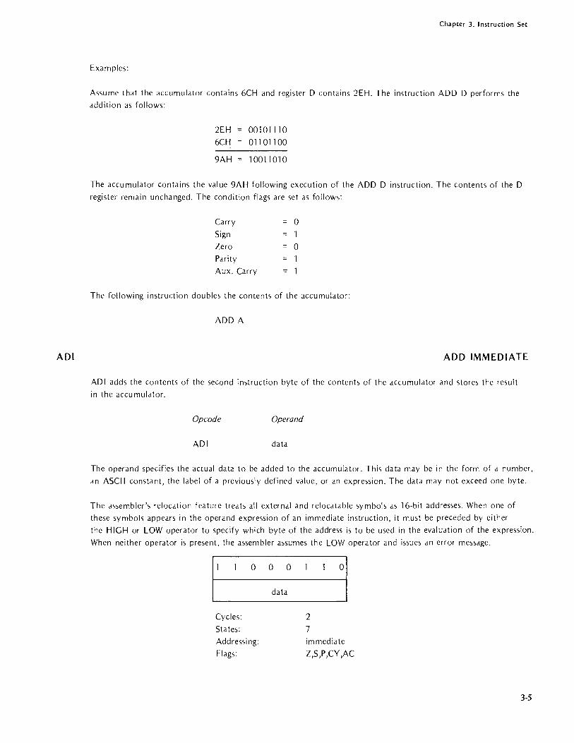
ADI
Chapter 3. Instruction Set
Examples:
Assume that the accumulator contains 6CH and register D contains 2EH. The instruction ADD D performs the
addition as follows:
2EH 001 0111 0
6CH 011011 00
9AH 1001 1010
The accumulator contains the value 9AH following execution of the ADD D instruction. The contents of the D
register remain unchanged. The condition flags are set as follows:
Carry 0
Sign 1
Zero 0
Parity =::
Aux. Carry
The following instruction double~ the contents of the accumulator:
ADD A
ADD IMMEDIATE
ADI adds the contents of the second instruction byte of the contents of the accumulator and stores the result
in the accumulator.
Opcode Operand
ADI data
The operand specifies the actual data to be added to the accumulator. This data may be in the form of a number,
an ASCII constant, the label of a previously defined value, or an expression. The data may not exceed one byte.
The assembler's relocation feature treats all external and relocatable symbols as 16-bit addresses. When one of
these symbols appears in the operand expression of an immediate instruction, it must be preceded by either
the HIGH or LOW operator to specify which byte of the address is to be used in the evaluation of the expression.
When neither operator is present, the assembler assumes the LOW operator and issues an error message.
000
data
Cycles:
Sta tes:
Addressing:
Flags:
o
2 7 immediate
Z,S,P,CY,AC
3-5

Chdpter 3. Instruction Set
ANA
3-6
Example:
A~sume that the accumulator contains the value 14H. The i,nstruction ADI 66 has the following effect.
Accumulator Immediate data
14H 42H
00010100 01000010 01 01 011 0 ,= 56H
Notice that the assembler converts the decimal value 66 into the hexadecimal value 42.
LOGICAL AND WITH ACCUMULATOR
ANA performs a logical AND operation using the content> of the specified byte and the accumulator. The result
is placed in the accumulator.
Summary of Logical Operations
AND produces a one bit in the result only W:len the corresponding bits in the test data and the mask data arc
ones.
OR produces d one bit in the result when the corresponding bits in eithel~ the test data or the mask data are ones.
Exclusive OR produces a one bit only when the corresponding bits in the test data and the mask data are different; i.e., a one bit in either the test dau or the mask data - but not both - produces a one bit in the result.
AND
1010 1010 0000 1111
0000 1010
AND Register with Accumulator
Opcode
ANA
OR
1010 1010 00001111
1010 1111
Operand
reg
EXCLUSIVE OR
1010 0000
1010
1010 1111
0101
The operand must specify one of the register·s A through E, H or L. This instruction ANDs the contents of the
specified register with the accumulator and stores the result in the accumulator. The carry flag is reset to zero.
! 1 0 0 0 I S S sl Cycles:
States: 4 Addressing: register Flags: Z,S,P,CY,AC

ANI
Chapter 3. Instruction Set
AND Memory with Accumulator
Opcode Operand
ANA M
This instruction ANDs the contents of the specified memory location with the accumulator and stores the re~ult
in the accumulator. The carry flag is reset to zero.
Example:
~ll ___ 0 ______ 0 __ 0 ______ l~ Cycles:
Sta tes: Addressing:
Flags:
2 7 register indirect
Z,S,P,CY,AC
Since any bit ANDed with a zero produces a zero and any bit ANDed with a one remains unchanged, AND is
frequently used to zero particular groups of bits. The following example ensures that the high-order four bits of the accumulator are zero, and the low-order four bits ar~ unchanged. Assume that the C register contain-; OFH:
Accumulator
C Register
1 1 1
o 000 000 0
o 0 1
o 0
OFCH
OFH
OCH
AND IMMEDIATE WITH ACCUMULATOR
ANI performs a logical AND operation using the contents of the second byte of the instruction and the accumu
lator. The result is pldced in the accumulator. AN I also resets the carry flag to zero.
Op co de Operand
ANI data
The operand must specify the data to be used in the AND operation. This data may be in the form of a number,
an ASCII constant, the label of some previously defined value, or an expression. The data may not exceed one
byte.
The assembler's relocation feature treats all external and relocatable symbols as 16-bit addresses. When one of
these symbols appears in the operand expres<;ion of an immediate instruction, it must be preceded by either the
HIGH or LOW operator to specify which byte of the address is to be used in the evaluation of the expression.
When neither operator is present, the assembler assumes the LOW operator and issues an error message.
3-7

Chapter J. Instruction Set
CALL
3-8
[
._0_0 ~ data ]
Cycles:
Sta tes:
Addressing:
Flags:
Summary of Logical Operations
2
7
immediate
Z,S,P,CY,AC
AND produce~ a one bit in the result only when the corresponding bits in the test data and the mask data are
ones.
OR produces a one bit in the result when the corresponding bits in either the test data or the mask data arc
ones.
Exclu~ive OR produces a one bit only when the corrcsponding bits in the test data and the mask data are
different; i.e., a one bit in eithcr thc test data or the mask data - but not both produces a onc bit in thc
result.
Example:
AND
1010 1010 0000 1111
0000 1010
OR
10101010 0000 1111 1010 1111
EXCLUSIVE OR
1010 1010 0000 1111 1010 OlOl
The following instruction is u'>ed to re~et OFF bit six of the byte in the accumulator:
ANI 101111118
Since any bit ANDed with d one remains unchanged and a bit ANDed with d zero i, rc'>t to lcro, thc ANI
instruction shown above scts bit six OFF and ledvc~ the othcr', unchangcd. This tcchniquc is u,eful when a
program uscs individual bits a<; slatus flags.
CALL
Thc CALL imtruction combincs functions of thc PUSH and J\1P instruction~. CALL pushcs the contents of the
program counter (the address of the ncxt sequential instruction) onto the stack and thcn jumps to the address
spccificd in the CALL instruction.
Edch CALL il1'.tructioll or one of it<; variant~ implie, thc use of a subsequent RET (return) imtruction. Whcn a
call hds no corre~pollding return, exccss addres'>c'> arc built up in thc stack.

Chapter 3. Instruct"lon Set
Opcode Operand
CALL address
The address may be specified as a number, a label, or an expression. (The label is most common.) The as'>embler
inverts the high and low address bytes when it assembles the instruction.
1 1 0
Cycles:
S ta tes:
Addressing:
Flags:
Example:
0 1 q 0 1
lowaddr
high addr
5 17 (18 on 8085)
immediate/register indilTct
none
When a given coding sequence is required several times in'a program, you can usually conserve memory by coding
the sequence as a subroutine invoked by the CALL instruction or one of it<, varianI',. For example, assume that
an application drives a six-digit L.ED display; the display is updated as a result of dn operator input or because
of two different calculations that occur in the program. The coding required to drive the display can be included
in-line at each of the three point, where it is needed, or it can be coded as a subroutine. If the label DISPL. Y is
assigned to the first instruction of the display driver, the following CAL.L. instruction is used to invoke the
display subroutine:
CAL.L. DISPL Y
This CALL. instruction pushes the addle)s of the next proglam instruction onto the stack and then transfers
control to the DISPL. Y subroutine. The DISPL. Y ,uilroutine must execute a return instruction or one of its
variants to resume normal program flow. The following is a graphic illustration of the effect of CAL.L and return
instructions:
CAL.L. -----
_; DISPL. Y:
CAL.L. ~ -f2..I~~Y_-_-_~~~ ___ ~ ------~RET
CA L. L. DISPL. Y
Consideration for Using Subroutlt7es
The larger the code segment to be repeated and the greater the number of repetitions, the greater the potential
memory savings of using a subroutine. Thu" if the display driver in the previou, example requires one hundrecl
3-9
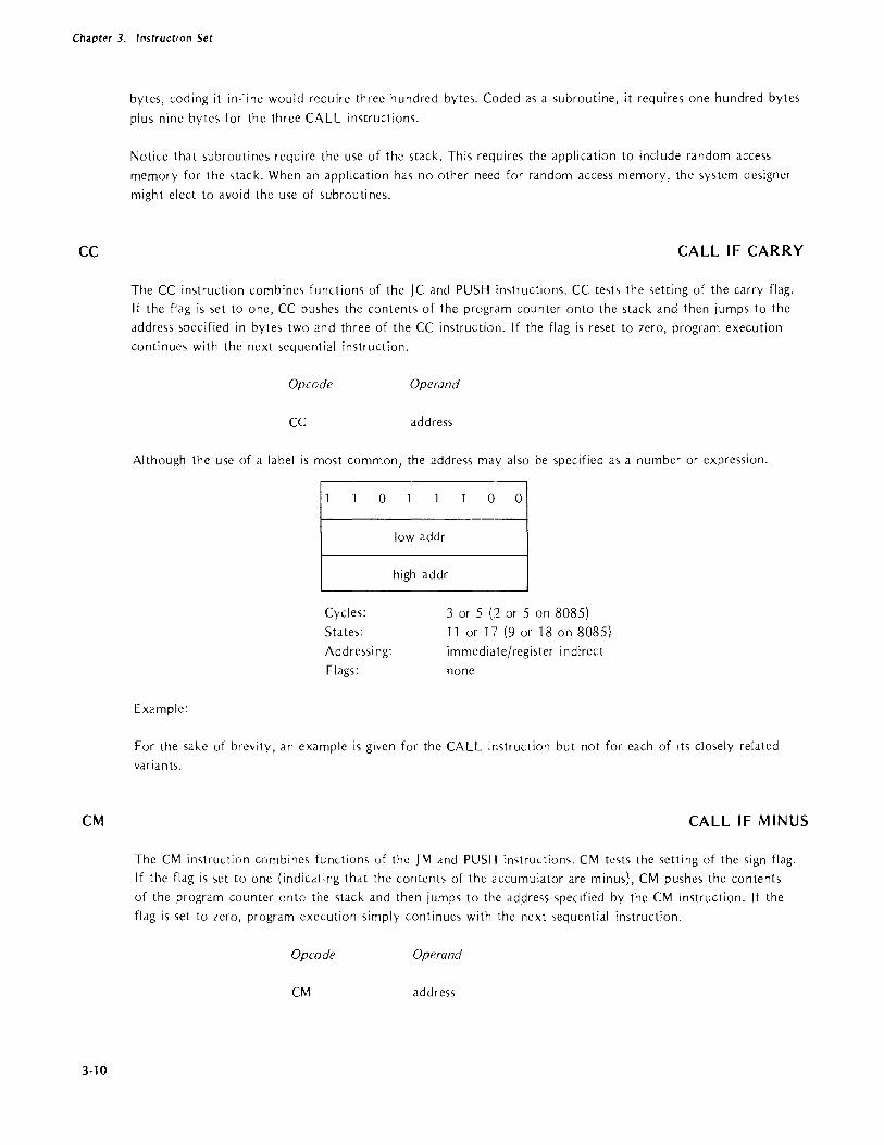
Chapter 3. Instruction Set
CC
CM
3-10
bytes, coding it in-line would require three hundred bytes. Coded as a subroutine, it requires one hundred bytes
plus nine bytes for the three CALL instructions.
Notice that subroutines require the use of the stack. This requires the application to include random access
memory for the stack. When an application has no other need for random access memory, the system designer
might elect to avoid the use of subroutines.
CALL IF CARRY
The CC instruction combines functions of the jC and PUSH instructions. CC tests the setting of the carry flag. If the flag is set to one, CC pushes the contents of the program counter onto the stack and then jumps to the address specified in bytes two and three of the CC instruction. If the flag is reset to zero, program execution
continues with the next sequential instruction.
Opcode Operand
CC address
Although the use of a label is most common, the address may also be specified as a number or expression.
Example:
o o 0
~---------------------------
Cycles:
States:
Addressi ng:
Flags:
lowaddr
high addr
3 or 5 (2 or 5 on 8085) 11 or 17 (9 or 18 on 8085) immediate/register indirect
none
For the sake of brevity, an example is given for the CALL instruction but not for each of ItS closely related
variants.
CALL IF MINUS
The CM instruction combines functions of the J M and PUSH instructions. CM tests the setting of the sign flag. If the flag is set to one (indicating that the contents of the accumulator are minus), CM pushes the contents
of the program counter onto the stack and then jumps to the address specified by the CM instruction. If the
flag is set to zero, program execution simply continues with the next sequential instruction.
Opcode Operand
CM address

CMA
Chapter 3. Instruction Set
Although the use of a label is most common, the address may also be specified as a number or an expression.
Example:
I--0~ lowaddr l
high addr ] L--_
Cycles:
States:
Addressing:
Flags:
3 or 5 (2 or 5 on 8085)
11 or 17 (9 or 18 on 8085)
immediate/register indirect
none
For the sake of brevity, an example is given for the CALL instruction but not for each of its closely related
variants.
COMPLEMENT ACCUMULATOR
CMA complements each bit of the accumulator to produce the one's complement. All condition flags remain
unchanged.
Opcode Operand
CMA
Operands are not permitted with the CMA instruction.
L-I 0_0 __ 0 ___ ~ Cycles:
States: 4 Flags: none
To produce the two's complement, add one to the contents of the accumulator after the CMA instructions has
been executed.
Example:
Assume that the accumulator contains the value 51 H; when complemented by CMA, it becomes OAEH:
51 H
OAEH
01010001
1010111 0
3-11

Chapter 3. Instruction Set
CMC
CMP
3·12
COMPLEMENT CARRY
If the carry flag equal,> zero, CMC set'> it to one. If the carr"y flag is one, CMC resets it to zero. All other flags
remain unchanged.
Opcode Operand
CMe
Operdnd~ Me not permitted with the CMC in'>truction.
Cycle'>:
States: 4
Flags: CY only
Example:
Assume thdt d program u'>es bit 7 of d byte to control whether" a ,>ubroutine i, called. To test the bit, the pro
gram loads the byte into the dccumulator, rotates bit 7 into the Cdrry flag, and execute, a CC (Call if Carry)
instruction. Before returning to the calling program, the subroutine reiniti,difes the flag byte u,>ing the following
code:
CMC
RAR
RET
;SET BIT 7 OFF
;ROTATE BIT 7 INTO ACCUMULATOR
;RETURN
COMPARE WITH ACCUMULATOR
CMP compar-e'> the ,>pecified byte with the content'> of the accumulator ,ltlel indicate'> the rC'>Lllt by '>etling the
carry dnd fero fidgS. The valuc~ being compdred remain unchanged.
The zero flag indicates equality. No carry indicates that the accumulator i'> greater than the specified byte; a
carry indicates that the accumulator is leS'> than the byte. However, the meaning of the CMrv flag is rever'>cd
when the values have different signs or one of the values i, complemented.
The program tests the condition flag'> using one of the conditional Jump, Cdl, m Return in<,lruction'>. For
example, JZ (jump if Zero) tcst', for equdlity.
Functional Description:
Compari.,ons are performed by subtracting the specified byte from the contents of the accumulator", which
is why the zero ,md cMry flags indicate the result. This subuaction uses the processor", interndl registers
so that source data is preserved. Because subtraction uscs two's complement addition, the CMP instruction
recomplements the carry flag generated by the subtraction.

Chapter 3. Instruction Set
Compare Register with Accumulator
Opcode Operand
CMP reg
The operand must name one of the registers A through E, H or L.
o S s] Cycles:
States: 4 Addressing: regis ter
Flags: Z ,S ,P ,CY ,AC
Compare Memory with Accumulator
Opcode Operand
CMP M
This instruction compares the contents of the memory location addressed by the Hand L registers with the
contents of the accumulator. M is a symbolic reference to the Hand L register pair.
Example 1:
I '--1_0 _____ 1_~ Cycles:
States:
Addressing:
Flags:
2 7
register indirect
Z,S,P,CY,AC
Assume that the accumulator contains the value OAH and regi,ter E contains the value OSH. The instruction CMP E performs the following internal subtraction (remember that subtraction is actually two's complement
addition) :
Accumulator +( -E Register)
00001010 11111011
00000101 +(-carry)
After the carry is complemented to account for the subtract operation, both the zero and carry bits arc zero, thus indicating A greater than E.
Example 2:
As'>ume that the accumulator contains the value --1 BH and register E contains OSH:
Accumulator +(E Register)
11100101
11111011 11100000 + (--carry)
3-13

Chapter 3. Instruction Set
CNC
CNZ
3·14
After the CMP instruction recomplements the carry flag, both the carry flag and zero flag are zero. Normally
this indicates that the accumula.tor is greater than register E. However, the meaning of the carry flag is reversed
since the values have different ~,igns. The user program is responsible for proper interpretdtion of the cdrry flag.
CALL IF NO CARRY
The CNC instruction combines functions of the JNC and PUSH instructions. CNC tesh the setting of the carry
flag. If the flag is set to lero, CNC pushes the contents of tre program counter onto the stack and then jumps
to the address specified by the CNC instruction. If the flag i'i set to one, program execution simply continue~
with the next sequential instruction.
Opcode. Operand
CNC address
Although the use of a Idbel is most common, the adclre~s may also be <,pecified as d number or an expression.
1 1 0
Cycles:
States:
Addressing:
Fldg.,:
Example:
1 0 1 (l 0
low dddr
high addr
3 or 5 (2 or 5 on 8085)
11 or 17 (9 or 18 on 8085)
immediate/register indirect
none
For the sake of brevity, an example is given for the CALL instructioJl but not fOl edch of ih clo'iely related
vdriants.
CALL IF NOT ZERO
The CNZ instruction combines functions of the JNZ and PUSH in,tructions. CNZ te'its the setting of the fero
fldg. If the flag is off (indicating that the contents of the accumulator are other than zero)' CNZ pushes the
contents of the program counter onto the stack and then jump'> to the address specified in the instruction's
second and third bytes. If the fldg is set to one, program execution 'iimplv continues with the next sequenti,li
instruction.
Op co de Operand
CNZ address
Although the use of d Idbel is most common, the address mel) also be "pccified d'i a number or an expression.

CP
Chapter 3. Instruction Set
1 1 0
Cycles:
States:
Addressing:
Flags:
Example:
0 0 1 0 0
low addr
high addr
3 or 5 (2 or 5 on 8085)
11 or 17 (9 or 18 on 8085)
immediate/register indirect
none
For the sake of brevity, an example is given for the CALL im.truction but not for each of its closely related
variants.
CALL IF POSITIVE
The CP instruction combines features of the J P and PUSH instructions. CP tests the setting of the sign flag. If the flag is set to zero (indicating that the contents of the accumulator are positive), CP pushes the contents of the program counter onto the stack and then jumps to the address specified by the CP instruction. If the flag is set to one, program execution simply continues with the next sequential instruction.
Opcode Operand
CP address
Although the use of a label is more common, the address may also be specified as a number or an expression.
1 1 1
Cycles:
S ta tes:
Ad dressi ng:
Flags:
Example:
1 0 1 0 0
low address
high addr
3 or 5 (2 or 5 on 8085)
11 or 17 (9 or 18 on 8085)
im mediate/register indirect
none
For the sake of brevity, an example is given for the CALL instruction but not for each of its closely related variants.
3-15

Chapter 3. Instruction Set
CPE
CPI
3-16
CALL IF PARITY EVEN
Parity is even if the byte in the accumulator has an even number of one bits. The parity flag is set to one to
indicate this condition. The CPE and CPO instructions are useful for testing the parity of input data. However,
the IN instruction does not set any of the condition flags. The flags can be set without altering the data by
adding OOH to the contents of the accumulator.
The CPE instruction combines functions of the J PE and PUSH instructions. CPE tests the setting of the parity
flag. If the flag is set to one, ePE pushes the contents of the program counter onto the stack and then jumps
to the address specified by the ClPE instruction. If the flag i, set to zero, program execution simply continues
with the next sequential instruction.
Opcode Operand
CPE address
Although the use of a label is more common, the address may also be <,pccified as a number or an expression.
1 1 1
Cycles:
States:
Ad dressi ng:
Flags:
Example:
0 1 1 0 0
low addr
high addr
3 or 5 (2 or 5 on 8085)
11 or 17 (9 or 18 on 8085)
immediate/register indirect
none
For the sake of brevity, an example is given for the CALL instruction but not for each of its closely related variants.
COMPARE IMMEDIATE
CPI compares the contents of the second instruction byte with the contents of the accumulator and sets the zero
and carry flags to indicate the result. The values being compared remain unchanged.
The zero flag indicates equality. hlo carry indicates that the contents of the accumulator are greater than the
immediate data; a carry indicates that the accumulator is less than the immediate data. However, the meaning
of the carry flag is reversed when the values have different signs or one of the values is complemented.
Op co de Operand
CPI data

CPO
Chapter 3. Instruction Set
The operand must specify the data to be compared. This data may be in the form of a number, an ASCII
constant, the label of a previously defined value, or an expression. The data may not exceed one byte.
The assembler's relocation feature treats all external and relocatable symbols as 16-bit addresses. When one of
these symbols appears in the operand expression of an immediate instruction, it must be preceded by either
the HIGH or LOW operator to specify which byte of the address is to be used in the evaluation of the
expression. When neither operator is present, the assembler assumes the LOW operator and issues an error
message.
Example:
J-----1.~ data ~
Cycles:
States:
Addressing:
Flags:
2 7 register indirect
Z,S,P,CY,AC
The instruction CPI 'C' compares the contents of the accumulator to the letter C (43H).
CALL IF PARITY ODD
Parity is odd if the byte in the accumulator has an odd number of one bit,. The parity flag is set to zero to
indicate this condition. The CPO and ePE instructions are useful for testing the parity of input data. However,
the IN instruction does not set any of the condition flags. The flags can be ,e1 without dltering the data by
adding OOH to the contents of the accumulator.
The CPO instruction combines functions of the J PO and PUSH instructions. CPO tests the setting of the parity
flag. If the flag is set to zero, CPO pushes the contents of the program counter onto the slack and then jumps
to the address specified by the CPO instruction. If the flag is set to one, program execution simply continues
with the next sequential instruction.
Op co de Operand
CPO address
Although the use of a label is more common, the address may also be specified as a number or an expression.
1 1 1 0 0 1 0 0
lowaddr
high addr
Cycles: 3 or 5 (2 or :5 on 8085)
States: 11 or 17 (9 or 18 on 8085)
Addressing: immediate/register indirect
Flags: none 3-17

Chapter 3. Instruction Set
CZ
DAA
3-18
Example:
For the sake of brevity, an example is given for the CALL in';truction but not for each of its closely related
variants.
CALL IF ZERO
The CZ instruction combines fU:lctions of the jZ and PUSH instructiom. CZ tests the setting of the zero flag.
If the flag is set to one (indicating that the contents of the accumulator arc lero), CZ pushes the contents of
the program counter onto the stack and then jumps to the address specified in the CZ instruction. If the flag
is set to tero (indicating that the content'> of the accumulator arc other tha.n leroj, program execution simply
continues with the next sequential instruction.
Opwde Operand
CZ address
Although the usc of a label is most common, the address may also be "pecified as a number or an expression.
Example:
o 0 o 0
~------------------------------
low addr ~-----------------------------
Cycles:
States:
Ad dressi ng:
Flags:
high addr
3 or 5 (2 or 5 on 8085)
1 I or 17 (9 or 18 on 8085)
immediate/register indirect
none
For the sake of brevity, an exalTlple is given for the CALL imtruction but not for each of its closely related
variants.
DECIMAL ADJ UST ACCUMULATOR
The DAA instruction adjusts the eight-bit value in the accumulator to form two four-bit hindry coded decimal
digits.
Opcode Operand
DAA
Operands arc not permitted with the DAA imtruction.
DAA is used when adding decimal numbers. It is the only instruction whose function requires use of the auxiliary
carry flag. In multi-byte arithmetic operations, the DAA instruction typically is coded immediately after the arith
metic instruction so that the auxiliary carry flag is not altered unintentionally.
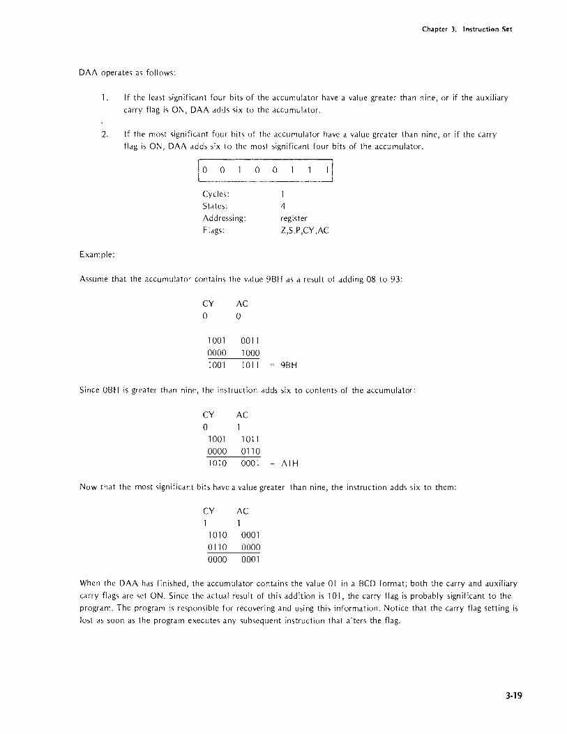
Chapter 3. Instruction Set
DAA operates as follows:
1. If the least significant four bits of the accumulator have a value greater than nine, or if the auxiliary
carry flag is ON, DAA adds six to the accumulator.
2. If the most significant four bits of the accumulator have a value greater than nine, or if the carry
flag is ON, DAA adds six to the most significant four bits of the accumulator.
Example:
I L(_) __ O ______ O ___ O _____ l_~ Cycles: States:
Addressing: Flags:
4
register
Z,S,P,CY,AC
Assume that the accumulator contains the value 9BH as a result of adding 08 to 93:
CY AC
o 0
1001 0011
0000 1000
1001 1011 = 9BH
Since OBH is greater than nine, the instruction adds six to contents of the accumulator:
CY AC
o 1001 1011 0000 0110 1010 0001 = AI H
Now that the most significant bits have a value greater than nine, the instruction adds six to them:
CY AC 1
1010 0001 0110 0000
0000 0001
When the DAA has finished, the accumulator contains the value 01 in a BCD format; both the carry and auxiliary
carry flags are set ON. Since the actual result of this addition is 101, the carry flag is probably significant to the
program. The program is responsible for recovering and using this information. Notice that the carry flag setting is
lost as soon as the program executes any subsequent instruction that alters the flag.
3-19

Chapter 3. Instruction Set
DAD
OCR
3-20
DOUBLE REGISTER ADD
DAD adds the 16·bit value in the specified register pair to the contents of the Hand L regi.,ter pair. The result
is stored in Hand L.
Op co de Operand
DAD
DAD may add only the contents of the B&C, D&E, H& L, or the SP (Stack Pointer) register pairs to the contents
of H&L. Notice that the letter H must be used to specify thdt the H&L register pair is to b~ added to itself.
DAD sets the carry flag ON if there is a carlY out of the Hand L registers. DAD ,tffects none of the condition
flags other than carry.
[ 0 0 R P
Cycles:
States:
Addressing:
Flags:
Examples:
3
10
register
CY
The DAD instruction provides a meam for '>dving the current contents of the stack pointer.
LXI H,OOH
DAD SP
SHLD SAVSP
;CLEAR H& L TO ZEROS
;GET SP INTO H&L
;STORE SP IN MEMORY
The instruction DAD H doubles the number in the Hand L registers except when the opeldtion Cduses a carry
out of the H register.
DECREMENT
DCR subtracts one from the contents of the specified byte. DCR dffects all the condition flags except the cdrry
f1dg. Because DCR preserves the carry f1dg, it Cdn be used within multi·byte arithmetic routines for decrementing chardcter counts and similar purposes.
Decrement Register
Op co de Operand
DCR reg

Chapter 3. Instruction Set
The operand must specify one of the registers A through E, H or L. Th~ instruction subtracts one from the
contents of the specified register ..
Cycles:
States:
Addressing:
Flags:
Decrement Memory
Orcade
DCR
5 (4 on 8085)
register
Z,S,P,AC
Operand
M
This instruction subtracts one from the contents of the memory location addressed by the Hand L registers.
M is a symbol ic reference to the Hand L registers.
Cycles:
States: Addressing: Flags:
Example:
o
3 10
O~
register indirect
Z,S,P,AC
The DCR instruction is frequently used to control multi-byte operations such as moving a number of characters from one area of memory to another:
MVI B,5H LXI H,260H
LXI D,900H LOOP: MOV A,M
STAX D DCX D DCX M
DCR B jNZ LOOP
;SET CONTROL COUNTER
;LOAD H,&L WITH SOURCE ADDR
;LOAD D&E WITH DESTINATION ADDR
;LOAD BYTE TO BE MOVED
;STORE BYTE
;DECREMENT DESTINATION ADDRESS ;DECREMENT SOURCE ADDRESS
;DECREMENT CONTROL COUNTER
;REPEAT LOOP UNTIL COUNTER=O
This example also illustrates an efficient programming technique. Notice that the control counter is decremented to zero rather than incremented until the desired count is reached. This technique avoids the need for a compare
instruction and therefore conserves both memory and execution time.
3-21

Chapter 3. Instruction Set
DCX
DI
3·22
DECREMENT REGISTER PAIR
OCX decrements the contents of the specified register pair qy one. OCX affects none of the condition flags.
Because OCX preserves all the flags, it can be used for address modification in any instruction sequence that
relies on the passing of the flags.
Op co de Operand
OCX
OCX may decrement only the B&C, O&E, H&L, or the SP (Stack Pointer) register pairs. Notice that the letter
H must be used to specify the Hand L pair.
Exercise care when decrementing the stack pointer as this causes a loss of synchronization between the pointer
and the actual contents of the stack.
Example:
~J __ O----'-_R __ P----'-__ O_ 1 3 Cycles:
States:
Addressing:
Flags:
5 (6 on 8085)
register·
none
A,sume that the Hand L registers contain the address 9800H when the instruction OCX H is executed. OCX
considers the contents of the two registers to be a single 16-bit value and therefore performs a borrow from the
H register to produce the value 97FFH.
DISABLE INTERRUPTS
The inter·rupt sy,tem is disabled when the processor recognizes an interrupt or immediately following execution
of a 01 instruction.
In applications that use interrupts, the 01 instruction is commonly used only when a code sequence must not be
interrupted. For example, time-dependent code sequences become inaccurate when interrupted. You can disable
the interrupt system by including a 01 imtruction at the beginning of the code sequence. Because you cannot
predict the occurrence of an IIlterrupt, include an E I instruction at the end of the time·dependent code sequence.
Opcode Operand
01
Operands are not permitted with the 01 instruction.
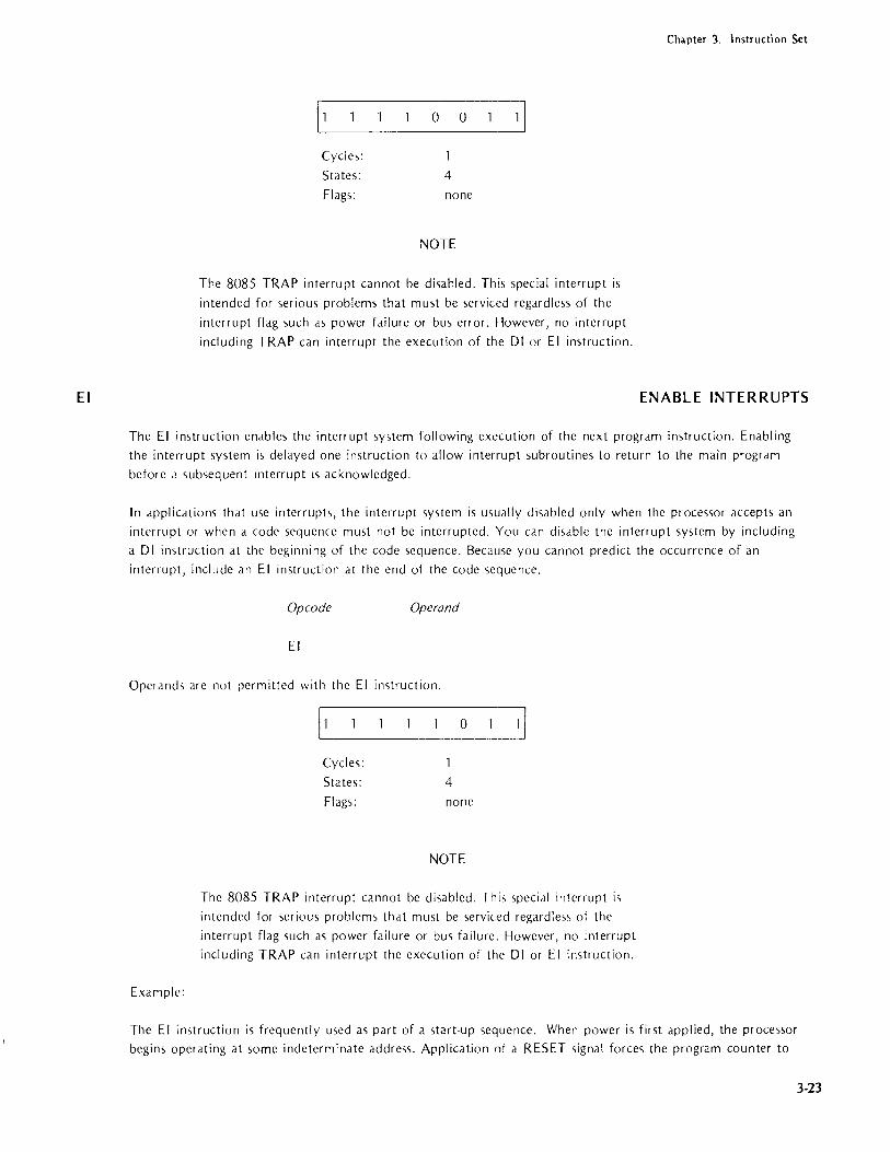
EI
Chapter 3. Instruction Set
IL1 ____________ 0 ___ 0 ___ l ~ Cycles:
States: 4
Flags: none
NOTE
The 8085 TRAP interrupt cannot be disabled. This special interrupt is
intended for serious problems that must be serviced regardless of the
interrupt flag such as power failure or bus error. However, no interrupt
including TRAP can interrupt the execution of the 01 or EI instruction.
ENABLE INTERRUPTS
The EI instruction enables the interrupt system following execution of the next program instruction. Enabling the interrupt system is delayed one instruction to allow interrupt subroutines to return to the main program
before 2 subsequent interrupt is acknowledged.
In applications that use interrupts, the interrupt system is usually disabled only when the processor accepts an
interrupt or when a code sequence must not be interrupted. You can disable the interrupt system by including a 01 instruction at the beginning of the code sequence. Because you cannot predict the occurrence of an
interrupt, include an EI instruction at the end of the code sequence.
Op co de Operand
EI
Operands are not permitted with the EI instruction.
Example:
Cycles:
States: 4
Flags: none
NOTE
The 8085 TRAP interrupt cannot be disabled. Thi'i special interrupt i'i
intended for serious problems that must be serviced regard Ie,., of the
interrupt flag such as power failure or bus failure. However, no interrupt including TRAP can interrupt the execution of the 01 or EI instruction.
The EI instruction is frequently used as part of a start-up sequence. When power is first applied, the processor begins operating at some indeterminate address. Application of a RESET signal forces the program counter to
3-23

Chapter 3. Instruction Set
HLT
IN
3-24
zero. A common instruction sequence at this point is EI, HL T. These instructions enable the interrupt system
(RESET also disables the interrupt system) and halt the processor. A subsequent manual or automatic interrupt
then determines the effective start-up address.
HALT
The HL T instruction halts tht~ processor. The program counter contains the address of the next sequential
instruction. Otherwise, the flags and registers remain unchanged.
[~ 0 13 Cycles:
States: 7 (5 on 8085)
Flags: none
Once in the halt state, the processor can be restarted only by an external event, typically an interrupt. Therefore,
you should be certain that interrupts are enabled before the HL T in'>truction i'> executed. See the description of
the EI (Enable Interrupt) instruction.
If an 8080 HL T instruction is executed while interrupts are disabled, the only way to restart the processor i,
by application of a RESET '>ignal. This forces the program counter to zero. The same is true of the 8085, except
for the TRAP interrupt, which i'i recognized even when the interrupt system is disabled.
The processor can temporarily Icave the halt state to service a direct memory access request. However, the pro·
cessor reenters the halt state once the request has been serviced.
A basic purpo,>e for the HL T instruction is to allow the processor to pause while waiting for an interrupt from a
peripheral device. However, a halt wastes processor resources dnd should be used only when there i'> no useful
processing task dVdilable.
INPUT FROM PORT
The IN instruction read'> eight bit'> of data from the specified port and load,> it into the dccumulator.
NOTE
This description is restricted to the exact function of the IN in'>truction.
Input/output structures are described in the 8080 or 8085 Microcomputer
Systems User's Manual.
Opcode Operand
IN exp
The operand expression may be a number or any expression that yield,> d value in the range OOH through OFFH.
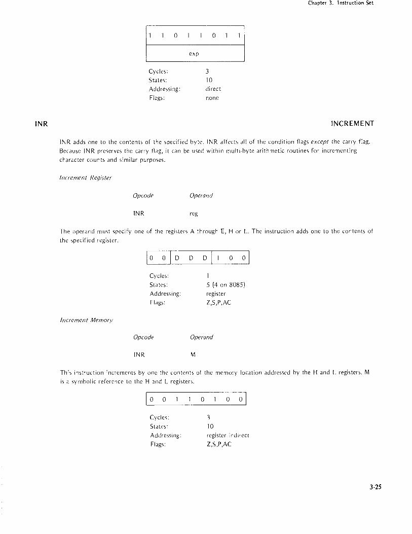
INR
Chapter 3. Instruction Set
[
__ 1 0 _011
exp J Cycles:
States: Addressing: Flags:
3
10 direct none
INCREMENT
INR add, one to the contents of the specified byte. INR affects all of the condition flags except the carry flag.
Because INR preserves the carry flag, it can be used within multi-byte arithmetic routines for incrementing
character counts and similar purposes.
Increment Register
Opcode Operand
INR reg
The operand must specify one of the registers A through E, H or L. The instruction adds one to the contents of
the specified register.
Increment Memory
[_O ___ O~_D ___ D ___ D~ ___ ~ Cycles:
Sta tes: Addressi ng:
Flags:
Opcode
INR
5 (4 on 8085)
register
Z,S,P,AC
Operand
M
This instruction increments by one the contents of the memory location addressed by the Hand L registers. M
is a ,ymbolic reference to the H Jnd L registers.
LIO ___ O _______ O _____ O~ Cycles:
States:
Addressing:
Flags:
3
10 register indirect
Z,S,P,AC
3-25

Chapter 3. IJntructioo Sct
INX
JC
3-26
Example:
If register C contains 99H, the instruction INR C increments the contents of the register to 9AH.
INCREMENT REGISTER PAIR
INX adds one to the contents of the specified register pair. INX affects none of the condition flags. Because
INX preserves all the condition flags, it can be used for address modification within multi-byte arithmetic
rou ti nes.
Opcode Operand
INX
INX may increment only the B&C, D&E, H& L, or the SP (Stack Pointer) register pairs. Notice that the letter H must be used to specify the Hand L register pair.
Exercise care when incrementing the stack pointer. Assume, for example, that INX SP is executed after a number
of item'> have been pushed onto ,he stack. A subsequent POP in'>truction accesses the high-order byte of the m,)st
recent stdck entry and the low-order byte of the next older entl·Y. Similarly, a PUSH instruction add,> the two
new bytes to the '>tack, but overlays the low-order byte of the most recent entry.
Cycles:
States:
Ad dressi ng:
Flags:
Example:
P 0 0
1 S (6 on SOSS)
regis ter
none
Assume that the D and E registers contain the value 01 FFH. The instruction INX D increments the value to
0200H. By contrast, the IN R E instruction ignores the carry out of the low-order byte and produces a result of
01 OOH. (This condition can be detected by testing the Zero condition flag.)
If the stack pointer regi'>ter contain'> the value OFFFFH, the instruction INX SP increments the contents of SP
to OOOOH. The INX in'>truction '>ets no flags to indicate this condition.
JUMP IF CARRY
The lC instruction tests the setting of the carry flag. If the flag is set to one, program execution resumes at thl!
address specified in the JC instruction. If the flag is reset to zero, execution continues with the next sequential
instruction.

JM
Chapter 3. Instruction Set
Opcode Operand
JC addres~
The address may be specified as a number, a label, or an expression. The assembler inverts the high and low
address bytes when it assembles the instruction.
1 1 0
Cycles:
States:
Addressing:
Flags:
Example:
1 1 0 1 0
lowaddr
high addr
3 (2 or 3 on 8085)
10 (7 or 10 on 8085)
immediate
none
Examples of the variations of the jump instruction appear in the description of the J PO instruction.
JUMP IF MINUS
The J M instruction tests the setting of the sign flag. If the contents of the accumulator are negative (sign flag = 1),
program execution re~umes at the address specified in the J M instruction. If the contents of the accumulator are positive (sign flag = 0), execution continues with the next sequential instruction.
Opcode Operand
JM address
The addres~ may be specified a~, a number, a label, or an expression. The assembler invert~ the high and low
address bytes when it assembles the instructions.
1 1 1
Cycles:
States:
Addressing:
Flags:
Example:
1 1 0 1 0
lowaddr
high addr
3 (2 or 3 on 8085)
10 (7 or 10 on 8085)
immediate
none
Examples of the variations of the jump instruction appear in the description of the J PO instruction.
3-27

Chapter 3. I nstruction Set
JMP
JNC
3-28
JUMP
The J MP instruction alters the execution sequence by loading the address in its second and third bytes into the
program cou nter.
Opcode Operand
JMP address
The address may be specified as a number, a label, or an expression. The as~embler inverts the high and low
address bytes when it assembles the address.
Example:
~.---------------------------,
o 0 0 0
low addr
high addr L... ___ •. ________________ _
Cycles:
States:
Ad dressi ng:
Flags:
3 10
immediate
none
Examples of the variations of the jump in<;truction appear in the description of thc J PO instruction.
JUMP IF NO CARRY
The JNC instruction tests the setting of the carry flag. If there is no carry (carry flag = 0), program execution
resumes at the address specified in the JNC instruction. If thcre is a carry (cdrry flag = 1), execution cuntinue'
with the next sequential instruction.
Opcode Operand
JNC addre~~
The address may be specified as a number, a label, or an expression. The assembler invert, the high dnd low
address bytes when it assembles the instruction.
I 1 0
Cycles:
States:
Addressing:
Flags:
1 0 0 I 0
low addr
high addr
3 (2 or 3 on 8085)
10 (7 or 10 on 8085)
immediate
none

JNZ
JP
Chapter 3. Instruction Set
Example:
Examples of the variations of the jump instruction appear in the description of the J PO instruction.
JUMP IF NOT ZERO
The J NZ instruction tests the setting of the zero flag. If the contents of the accumulator are not zero (zero
flag = 0), program execution resumes at the address specified in the JNZ instruction. If the contents of the
accumulator are zero (zero flag = 1), execution continues with the next sequential instruction.
Opcode Operand
JNZ address
The address may be specified as a number, a label, or an expression. The assembler inverts the high and low
address bytes when it assembles the instruction.
Example:
o 0 0 0 0
~-----------------------------
Cycles:
States:
Addressing:
Flags:
lowaddr
high addr
3 (2 or 3 on 8085) 10 (7 or 10 on 8085) immediace
none
Examples of the variation'> of the jump instruction appear in the description of the J PO instruction.
JUMP IF POSITIVE
The J P instruction te'>t<, thc setting of the sign flag. If thc contcnts of the accumulator are positive (sign flag c= 0),
program cxccution rcsumes at the address specified in thc JP in~truclion. If the contents of the accumulator arc
minus (sign flag = 1), cxecution continues with thr, next sequential instruction.
Op co de Operand
JP addre'>s
The addrcs,> may bc specificd a, a number, a label, or an expre.,,,ion. Thc asscmblcr invert'> the high and low urdcl
audrc'>s bytcs when it assembles the instruction.
3-29

Chapter 3. Instruction Set
JPE
3-30
Cycles:
States:
Addressi ng:
Flags:
Example:
o 0 0
low addr
high addr
3 (2 or 3 on 8085)
10 (7 or 10 on 8085)
immediate
none
EXJmples of the variations of the jump instruction dPpear in the description of the J PO instruction.
JUMP IF PARITY EVEN
Parity is even if the byte in the accumulator has an even number of one bit>. The parity fldg i~ set to one to
indicate this condition.
The J PE instruction tests the setting of the pdrity flag. If the parity flag is set to one, program execution resumes
dt the dddress specified in the J PE instruction. If the flag is re~et to fero, execution continues with the next
sequential instruction.
Opcode Operand
JPE
The dddress may be specified as a number, d Idbel, or an expres,>ion. The ds>embler inverts the high and low
addre'>s bytes when it dssembles the instruction.
The J PE dnd J PO (jump if parity odd) instructions dre especidlly useful for te<,\ing the parity of input data.
However, the IN imtruction docs not set dny of the condition flag,. The flag'> can be '>et by adding OOH to the
contents of the accumulator.
Cycle,:
Stdte,>:
Addres,ing:
Flags:
Example:
o o o
low addr
high addr
3 (2 or 3 on 8085)
10 (7 or 10 on 8(85)
immediate
none
Examples of the variations of the jump instruction appear In the description of the JPO instruction.

JPO
Chapter 3. Instruction Set
JUMP IF PARITY ODD
Parity is odd if the byte in the accumulator has an odd number of one bits. The parity flag is set to zero to
indicate this condition.
The J PO instruction tests the setting of the parity flag. If the parity flag is reset to zero, program execution
resumes at the address specified in the J PO instruction. If the flag is set to one, execution continues with the
next sequential instruction.
Opcode Operand
JPO address
The address may be specified as a number, a label, 01" an expre,,>ion. The as'>embler invert, the high and low
address bytes when it assembles the instruction.
The J PO and J PE (jump if parity even) instruction~ are especi,lIly u,ciul tor tf'qing the parity of input data.
However, the IN instruction does not set any of the condition flag'>. The flag, Cdn be ,et by adding OOH to the
contents of the accumulator.
1 1 1
Cycles:
States:
Addressing:
Flags:
Example:
0 0 0 I 0
low addr
high addr
3 (2 or 3 on 8085)
10 (7 or 10 on 8085)
immediate
none
This example shows three different but equivalent rTlethod,> fur jumping to one of two poinh in a prograrTl hd'cd
upon whether or not the Sign bit of a number is '>et. A<;sume that the hyte to be te'>tcd i~ the C regi<;ter.
Label Code Operand
ONE: MOV A,C
ANI 80H
JZ PLUS jNZ MINUS
TWO: MOV A,C
RLC
jNC PLUS
jMP MINUS
THREE: MOV A,C ADI 0
JM MINUS
PLUS: ;SIGN BIT RESET
MINUS: ;SIGN BIT SET 3-31

Chapter 3. Instruction Set
JZ
LOA
3-32
The AND immedidte instruction in block ONE zeroes all hils of the ddta byte except the Sign bit, which re
maim unchanged. If the Sign bit WdS 1ero, the Zero condition bit will he set, and the JZ instruction will cause
progrdm control to be trdnsferred tu the instruction dt PLUS. Otherwi.,e, the JZ in,truction will merely update
the progrdm counter hy three, dnd the JNZ instruction will he executed, causing control to be transferred to
the instruction at MINUS. (The Zero bit is undffected by dll jump instructions.)
The RLC instruction in block TWO cau,e, the Carry bit tu be set equal to the Sign bit of the data byte. If the
Sign bit was reset, the JNC instrllction causes a iump To PLUS. Otherwise the JMP instruction is executed,
unconditionally transferring control to MINUS. (Note that, in thi'i instdnce, a JC instruction could he suh
'itituted for the unconditional iump with identical results.)
The add immedidte instruction in block THREE causes the condition hits to be set. If the sign bit was set, the
J M instruction Cd uses program control to he trdnsferred to MINUS. Otherwise, program control flows auto
mdtically into the PLUS routine.
JUMP IF ZERO
The JZ instruction te.,ts the '>etting of the zero tllg. If the fldg is set to one, program execution resumes at the
dddres'i specified in the JZ instruction. If the flag i, reset to lero, execution continues with the next sequentidl
ins tr uc t ion.
Op co de Operand
JZ
The address may he specified as a number, d label, or dn expre<,sion. The dssemhler invert<; the high dnd low
address bytes when it assemble'i the instruction.
Example:
o 0 o o
Cycles:
States:
Addre<"ing:
Flags:
low addr
high addr
3 (2 or 3 (In 8085)
10 (7 or 10 on 8085)
immediate
none
EXMnple., of the vdridtions of the iump instruction dPpear in the description of the JPO instruction.
LOAD ACCUMULATOR DIRECT
LDA loads the accumuldtor with a copy of the byte at the location specified in bytes two and three of the
LDA instruction.

LDAX
Chapter 3. I nstruction Set
Opcode Operand
LOA address
The addre55 may be stated as a number, a previously defined label, or an expre55ion. The assembler inverts the
high and low addre55 bytes when it builds the instruction.
0 0 1
Cycles: States:
Addressing: Flags:
Examples:
1 1 0
lowaddr
high addr
4
13 direct
none
1 0
The following instructions are equivalent. When executed, each replaces the accumulator contents with the byte
of data stored at memory location 300H.
LOAD: LOA
LOA LOA
300H 3*( 16*16) 200H+256
LOAD ACCUMULATOR INDIRECT
L OAX loads the accumulator with a copy of the byte stored at the memory location addressed by register pair
B or register pair O.
Opcode Operand
LOAX
The operand B specifies the Band C register pair; 0 specifie<, the 0 and E register pair. This instruction may
specify only the B or 0 register pair.
loooirl 0 1~
Cycles:
States: Addressing:
Flags:
~
II.....-___ fo := register pair B
l1 := register pair 0
2
7 register indirect
none
3-33

cnarHer 3. Instruction .set
Example:
Assume that register D contains 93H and register E contains SBH. The following instruction loads the accumulator
with the contents of memory location 938BH:
LDAX D
LHLD LOAD HAND L DIRECT
3·34
LHLD loads the L register with a copy of the byte stored itt the memory location specified in bytes two and
three of the LHLD instruction. LHLD then loads the H register with a copy of the byte stored at the next
higher memory location.
Opcode Operand
LHLD address
The address may be stated as a number, a label, or an expression.
Certain instructions usc the symbolic reference M to access the memory location currently specified by the Hand
L registers. LH LD is one of the instructions provided for loading new addresses into the H dnd L registers. The
user may also load the current top of the stack into t.he Hand L regiqers (POP instruction). Both LHLD and
POP replace the contents of the Hand L registers. You can also exchange the content> of H ,lnd L with the D
and E registers (XCHG instruction) or the top of the stack (XTHL instruction) if you need to ,ave the current
Hand L register'> fur subsequent use. SHLD stores Hand L in memury.
0 0 0 0
~ luw addr
high addr j Cycles: 5
States: 16
Addres<,i ng: direct
Flags: none
Example:
Assume that location<, 3000 and 3001 H contain the addre'>, 064EH ,tored in the form.!t 4EO('. In the following
sequence, the MOV instruction moves J copy of the byte stored at address Oh4E into the aC(Jmulator:
LHLD
MOV
3000H
A,M
;SET UP ADDRESS
;LOAD ACCur\1 FROM ADDRESS

LXI
Chapter 3. Instruction Set
LOAD REGISTER PAIR IMMEDIATE
LXI is a three-byte instruction; its second and third bytes contain the source data to be loaded into a register
pair. LXI loads a register pair by copying its second and third bytes into the specified destination register pair.
Opcode Operand
LXI
The first operand must specify the register pair to be loaded. LXI can load the Band C register pair, the D and
E register pair, the Hand L register pair, or the Stack Pointer.
The second operand specifies the two bytes of data to be loaded. This data may be coded in the form of a num
ber, an ASCII constant, the label of some previously defined value, or an expression. The d,fta must not exceed
two bytes.
LXI is the only immediate instruction that accepts a 16-bit value. All other immediate instructions require 8-bit
values.
Notice that the assembler inverts the two bytes of data to create the format of an address stored in memory.
LXI loads its third byte into the first register of the pair and its second byte into the second register of the
pair. This has the effect of reinverting the data into the format required for an address stored in registers. Thus,
the instruction LXI B,'AZ' loads A into register Band Z into register C.
Examples:
o olR plo 0 0
low-order data
~--------------------------
high -order data
Cycles: S ta tes: Addressing:
Flags:
3
10 immediate none
A common use for LXI is to establish a memory address for use in subsequent instructions. In the following
sequence, the LXI instruction loads the address of STRNG into the Hand L registers. The MOY instruction then
loads the data stored at that address into the accumulator.
LXI H,STRNG ;SET ADDRESS
MOY A,M ;LOAD STRNG INTO ACCUMULATOR
The following LXI instruction is used to initialize the stack pointer in a relocatable module. The LOCATE pro
gram provides an address for the special reserved label STACK.
LXI SP,STACK
3-35

Chapt~T 3. ImtTu~tion Set
MOV
3-36
MOVE
The MOV instruction moves one byte of data by copying the source field into the destination field. Source data
remains unchanged. The instruction's operands specify whether the move is from register to register, from a
register to memory, or from memory to a register.
Move Register to Register
Op co de Operand
MOV regl,reg2
The instruction copies the contents of reg2 into regl. Each operand must specify one of the registers A, B, C, D, E, H, or L.
When the same register is specified for both operands (as in MOV A,A), the MOV functions as a NOP (no operation) since it has no other noticeable effect. This form of MOV requires one more machine state than NOP, and therefore has a slightly longer execution time than NOP. Since M addresses a register pair rather than a byte of data, MOV M,M is not allowed.
D
Cycles:
States:
Addressing:
Flags:
Move to Memory
Opcode
MOV
D D 5 5 5 I
5 (4 on 8085) register
none
Operand
M,r
This instruction copies'the contents of the specified register into the memory location addressed by the Hand L
registers. M is a symbolic reference to the Hand L register pair. The <,econd operand must address one of the registers.
[0 0 5 5 51
Cycles: 2 5 ta tes: 7 Addressing: regis ter indirect Flags: none
Move from Memory
Op co de Operand
MOV r,M

MVI
Chapter 3. Instruction Set
This instruction copies the contents of the memory location addressed by the Hand L regi,ters into the specified
·register. The first operand must name the destination register. The second operand must be M. M is a symbolic
reference to the Hand L registers.
10 ID Cycles:
States:
Addressing:
Flags:
Examples:
Label Opcode
LDACe: MOV
MOV
NULOP: MOV
D D
2 7
register
none
Operands
A,M
E,A
C,C
~
indirect
Comment
;LOAD ACCUM FROM MEMORY
;COPY ACCUM INTO E REG
;NULL OPERATION
MOVE IMMEDIATE
MVI is a two-byte instruction; its second byte contains the source data to be moved. MVI moves one byte of
data by copying its second byte into the destination field. The instruction's operands specify whether the move
is to a register or to memory.
Move Immediate to Register
Opcode Operand
MVI reg,data
The first operand must name one of the registers A through E, H or L as a destination for the move.
The second operand specifies the actual data to be moved. This data may be in the form of a number, an ASCII
constant, the label of some previously defined value, or an expression. The data must not exceed one byte.
The assembler's relocation feature treats all external and relocatable symbols as 16·bit addresses. When one of
these symbols appears in the operand expression of an immediate instruction, it must be preceded by either the
HIGH or LOW operator to specify which byte of the address is to be used in the evaluation of the expression.
When neither operator is present, the assembler assumes the LOW operator and issues an error message.
0 0 D D D j data
Cycles: 2 States: 7 Addressing: immediate
Flags: none
3-37

ChdlJlCr 3. Instructi"n Set
NOP
ORA
3-38
Move Immediate to Memory
Opcode Operand
MVI M,data
This instruction copies the data stored in its second byte into the memory location addressed by Hand L. M is
a symbolic reference to the Hand L register pair.
Examples:
~_·1 __ 0 _----;0
C data
Cycles:
S ta tes:
Addrcs,ing:
Flag,:
3
10
immedia te/register indirect
none
The following examples show a number of methods for defining immediate data in the MVI instruction. All of
the examples generate the bit pattern for the ASCII character A.
MVI
MVI
MVI
MVI
MVI
MVI
M,01000001 B
M,'A'
M,41H
M,101Q
M,65
M,5+30*2
NO OPERATION
NOP performs no operation and affeels none of the condition flags. NOP is useful as filler in a timing loop.
Opcode Operand
NOP
Operands are not permitted with the NOP instruction.
INCLUSIVE OR WITH ACCUMULATOR
ORA performs an inclusive OR logical operation using the content<; of the specified byte and the accumulator. The
result is placed in the accumulator.

Chapter 3. Instruction Set
Summary of Logical Operations
AN D produces a one bit in the result only when the corresponding bits in the test data and the mask data are
one.
OR produces a one bit in the result when the corresponding bits in either the test data or the mask data are
ones.
Exclusive OR produces a one bit only when the corresponding bits in the test data and the mask data are different; i.e., a one bit in either the test data or the mask data - but not both - produces a one bit in the
result.
AND
1010 1010
0000 1111
0000 1010
OR Register with Accumulator
Op co de
ORA
OR
10101010
0000 1111
1010 1111
Operand
reg
EXCLUSIVE OR
10101010
0000 1111
10100101
The operand must specify one of the registers A through E, H or L. This instruction ORs the contents of the
specified register and the accumulator and stores the result in the accumulator. The carry and auxiliary carry
flags are reset to zero.
o
Cycles:
States: Addressing:
Flags:
OR Memory with Accumulator
Opcode
ORA
o S <~ 1
4
register
Z,S,P,CY,AC
Operand
M
The contents of the memory location specified by the Hand L registers are inclusive-ORed with the contents of the accumulator. The result is stored in the accumulator. The carry and auxiliary carry flags are reset to zero.
~ ___ 0 ________ 0 ______ 1_~ Cycles: States: Addressing:
Flags:
2 7
register indirect
Z,S,P,CY,AC
3-39

Chapter 3. Instruction Sct
ORI
3-40
Example:
Since any bit inclusive·ORed with a one produces a one and any bit ORed with a zero remains unchanged, ORA
is frequently used to set ON particular bits or groups of bits. The following example ensures that bit 3 of the
accumulator is set ON, but the remaining bits are not disturbed. This is frequently done when individual bits
are used as status flags in a program. Assume that I·egister D contains the value 08H:
Accumulator
Register D
o 0 0 0 0 1 o 0 0 0 000 000 0
INCLUSIVE OR IMMEDIATE
ORI performs an inciu,ive OR logical operation using the contents of the second byte of the instruction and the
contents of the accumulator. The re,ult is placed in the accumulator. ORI also resets the carry and auxiliary
carry flags to zero.
Opcode Operand
ORI data
The operand must specify the data to be used in the inclusive OR operation. This data may be in the form of a
number, an ASCII constant, the label of some previously defined value, or an expression. The data may not
exceed one byte.
The assembler's relocation feature treats all external and relocatable symbols a, 16·bit addresses. When one of
these symbols appears in the operand expression of an immediate instruction, it must be preceded by either the
HIGH or LOW operator to specify which byte of the address is to be used in the evaluation of the expression.
When neither operator is present, the assembler assume the LOW operator and i,sues (In error message.
Cycles:
S ta te'):
Addressing:
Flags:
Summary of Logical Operations
o
data
o
2
7
immediate
Z,S,P,SY,AC
AND produce, a one bit in the result only when the corresponding bib in both the test data and the mask data are ones.
OR produce, a one bit in the result when the corresponding bits in either the test data or the ma,k data arc ones.
Exclusive OR produce" a one bit only when the corresponding bit> in the test data and the ma,k data arc
different; i.e., a one bit in either the test data or the mask data ... but not both produces a one bit in the re,ult.
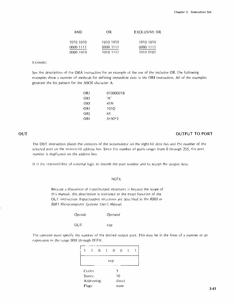
OUT
Chapter 3. Instruction Set
Example:
AND
1010 1010 0000 1111 0000 1010
OR
1010 1010 00001111 1010 1111
EXCLUSIVE OR
1010 1010 0000 1111 1010 0101
Sec the description of the ORA instruction for an example of the use of the inclusive OR. The following
examples show a number of methods for defining immediate data in the ORI instruction. All of the examples
generate the bit pattern for the ASCII character A.
ORI
OR!
ORI
OR!
OR!
OR!
010000018
'A'
41H
101Q
65 5+30*2
OUTPUT TO PORT
The OUT instruction places the contents of the accumulator on the eight-bit data bus and the number of the selected port on the sixteen-bit address bus. Since the number of ports ranges from 0 through 255, the port number is duplicated on the address bus.
It is the responsibility of external logic to decode the port number and to accept the output data.
NOTE
Because a discussion of input/output structures is beyond the scope of this manual, this description is restricted to the exact function of the
OUT instruction. Input/output structures are described in the 8080 or
8085 Microcomputer Systems User's Manual.
Opcode Operand
OUT exp
The operand must specify the number of the desired output port. This may be in the form of a number or an
expre<,sion in the rdnge OOH through OFFH.
[_0 ,-xpo ° 1 j.
Cycles:
States: Addressing: Flags:
3 10 direct
none 3-41

Chapter 3. Instruction Set
PCHL
POP
3-42
MOVE H&L TO PROGRAM COUNTER
PCHL loads the contents of the Hand L registers into the program counter register. Because the processor
fetches the next instruction from the updated program counter address, PCHL has the effect of a jump instruc·
tion.
Opcode Operand
PCHL
Operands are not permitted with the PCHL instruction.
PCHL moves the contents of the H register to the high-order' eight bits of the program counter and t.he contents of the L register to the low·order eight bits of the program counter.
The user program must ensure tl.at the Hand L registers contain the addres~ of an executable instructio 1 when the PCHL instruction is executed.
Cycles:
States:
Addressi ng: Flags:
Example:
000
1
5 (6 on 8085)
register
none
One technique for passing data to a subroutine is to place the data immediately dfter the subroutine call. The
return address pu~hed onto the stack by the CALL instruction actually addresses the data rather than the next instruction after the CALL. For this example, assume that two bytes of data follow the subroutine call. The following coding sequence performs a return to the next instruction after the call:
GOBACK: POP H INR L INR L
PCHL
;GET DATA ADDRESS ;ADD 2 TO FORM
;RETURN ADDRESS
;RETURN
POP
The POP instruction removes two bytes of data from the stack and copies them to a register pair or copies the Program Status Word into the accumulator and the condition flags.
POP Register Pair
POP copies the contenb of the memory location addressed by the stack pointer into the low·order regis .er of the regi,ter pair. POP then increments the stack pointer by one and copies the contents of the resulting addl'ess into

Chapter 3. Instruction Set
the high-order register of the pair. POP then increments the stack pointer again so that it addresses the next
older item on the stack.
Opcode Operand
POP {L} The operand may specify the B&C, D&E, or the H&L register pairs. POP PSW is explained '>eparately.
Cycles:
States:
Addressing:
Flags:
POP PSW
P 0 0 ~
3 10
register indirect
none
POP PSW use'> the contents of the memory location specified by the stack pointer to restore the condition flags.
POP PSW increments the stack pointer by one and restores the contents of that address to the accumulator.
POP then increments the stack pointer again so that it addresses the next older item on the stack.
Example:
c==_1 _________ 0 0 ~ Cycles:
Stdles:
Addressing:
Flag'>:
3 10
register indirect
l,S ,P ,CY ,AC
A"ume that a 'iubroutine is called because of an externdl interrupt. In generdl, such subroutines should SJve and
restore any registers it uses so that main program Cdn continue normally when it regaim control. The foliowing
sequence of PUSH and POP instructions save and re,tore the Program Status Word and all the registers:
343

Chapter 3. Instruction Set
PUSH
344
PUSH PSW
PUSH B
PUSH D
PUSH H
subroutine coding
POP
POP
POP
POP
RET
H
D B PSW
Notice that the ;equence of the POP instructions is the opposite of the PUSH instruction <,equence.
PUSH
The PUSH instruction copies two bvtes of data to the ,tdck. Thi~ ddta may be the contenh of a register pair or
the Program Status Word, d, explained below:
PUSH Register Pair
PUSH decrement, the stack pointer register- by one and copies the content, of the high-order regi,tcr of the
register pdir to the resulting address. PUSH then decrement; the pointer again dnd copie<, the low-order regi<,ter
to the resulting addre<'s. The source registers remain unchanged.
Opcode Operand
PUSH
The operand may specify the B&C, D&E, or- H&L register pair,. PUSH PSW is explained ,cpdrdtely.
Example:
~ __ I~1 _R __ P~O ____ O __ ~1 I Cycle,>:
States:
Addressi ng:
Flags:
3
11 (13 on 8085)
register indirect
none
Assume that register B contains 2AH, the C register- cont,dins 4CH, and the stack pointer is set at 9AAF. The
instruction PUSH B stores the B register at memory addre,s 9AAEH and the C register at 9AADH. The stack
pointer is set to 9AADH:

RAL
Chapter 3. Instruction Set
Stack Stack
Before PUSH Address After PUSH
SP before .. xx 9AAF xx
xx 9AAE 2A
xx 9AAD 4C ... SP after
xx 9AAC xx
PUSH PSW
PUSH PSW copies the Program Status Word onto the stack. The Program Status Word comprises the contents of the accumulator and the current settings of the condition flags. Because there are only five condition flags, PUSH PSW formats the flags into an eight-bit byte as follows:
7 6 543 2 0
~S~_z~_o~I_AC_I_o~l_p~~I~c_Y~l
On the 8080, bits 3 and 5 are always zero; bit one is always set to one. These filler bits are undefined on the
8085.
PUSH PSW decrements the stack pointer by one and copies the contents of the accumulator to the resulting
address. PUSH PSW again decrements the pointer and copies the formatted condition flag byte to the resulting
address. The contents of the accumulator and the condition flags remain unchanged.
Cycles:
States:
Addressing:
Flags:
Example:
o o 2J 3
11 (12 on 8085)
register indirect
none
When a program calls subroutines, it is frequently necessary to preserve the current program status so the calling program can continue normally when it regains control. Typically, the subroutine performs a PUSH PSW prior to execution of any instruction that might alter the contents of the accumulator or the condition flag settings. The subroutine then restores the pre-call system status by executing a POP PSW instruction just before returning control to the calling program.
ROTATE LEFT THROUGH CARRY
RAL rotates the contents of the accumulator and the carry flag one bit position to the left. The carry flag, which
is treated as though it were part of the accumulator, transfers to the low-order bit of the accumulator. The high
order bit of the accumulator transfers into the carry flag.
Opcode Operand
RAL
Operands are not permitted with the RAL instruction.
345

Chapter 3. Instruction Set
RAR
3-46
Example:
I ° ° ° __ o ___ -----i' I
Cycles:
States:
Flag'>:
4
CYonly
Assume that the dccumulator contains the I'alue OAAH and the carry flag is zero. The following diagrams illus
trate the effect of the RAL instruction:
Before: Carry
.---------. ° f--------------, Accumulator
_o ____ o ___ o __ -----i°l
After: Carry
[i]
Accumulator
10
° ° ° 01
ROTATE RIGHT THROUGH CARRY
RAR rotates the content, of the accumulator and the carry flag one bit pmition to the right. The carry flag,
which is treated a, though it were pdrt of the accumulator, trdnsfer', to the high-order bit of the accumulator.
The low-order bit of the dccumulator transfers into the carry flag,
Opcode Operand
RAR
Operand, are not permitted with the RAR imtr'uction,
10 ° 0
Cycles:
States:
Flags:
4
CYonly

RC
Chapter 3. Instruction Set
Example:
Assume that the accumulator contains the value OAAH and the carry flag is Lero. The following diagrams illus
trate the effect of the RAR in',truction:
Before: Carry
o
Accumulator·
o o o o
After: Carry
Accumulator
10 o o o
RETURN IF CARRY
The RC instruction tests the carry flag. If the fldg is set to one to indicate a Cdrry, the instruction pops two
bytes off the stack and places them in the program counter. Program execution resumes at the new address in
the program counter. If the flag i, Lero, program execution simply continue, with the next ,equential instruction.
Op co de Opemnd
RC
Operands are not permitted with the RC instruction.
o
Cycles:
Stdtes:
Addressing:
Flags:
Example:
o 0 0 I 1 or 3
5 or 11 (6 or 12 on 8(85)
register indirect
nOlle
For the sake of brevity, an example i, given for the RET instruction but not for each of ib closely related variants.
347

Chapter 3. Instruction Set
RET RETURN FROM SUBROUTINE
The RET in~truction pops two bytes of data off the stack and places them in the program counter register.
Program execution resumes dt the new address in the program counter.
Typically, RET instructions are used in conjunction with CALL instructions. (The same is true of the variants
of these instructions.) In thi'; case, it is assumed that the data the RET instruction pops off the stack is a
return address placed there by a previous CALL. This has the effect of returning control to the next instruction
after the CALL. The user must be certain that the RET instruction finds the address of executable code on the
stack. If the instruction finds the addre~, of data, the proce';sor attempts to execute the data as though it were
code.
Opcode Operand
RET
Operands are not permitted with the RET instruction.
Example:
o 0 o (~ L-__________________ _
Cycles:
States:
Ad dressi ng:
Flags:
3
10
register indirect
none
As mentioned previously, ~ubroutines un be nested. That is, a ~ubroutine can cdll a subroutine that calls
another subroutine. The only practical limit on the number of ne')ted cdlb is the amount of memory available
for stacking return addresse". A nested subroutine can even call the subroutine that called it, as shown in the
following example. (Notice that the program must contdin logic th.!t eventually returns control to the main
program. Otherwise, the two subroutines will cdll edch othel indefinitely.)
MAIN PROGRAM 1 SUBA t~~~~~~ ~~S~BB 1 ~ 7- ~~CALLSUBA
CALL SUBA CNZ SUBI3 ., ~ T T~ T~~
___________ ., ., ., ., ., RET
RET .,
RIM (8085 PROCESSOR ONLY) READ INTERRUPT MASK
348
The RIM instruction loads eight bits of data into the accumulator. The resulting bit pattern indicates the current
setting of the interrupt mask, the setting of the interrupt flag, pending interrupts, and onl:' bit of serial input data,
if any.
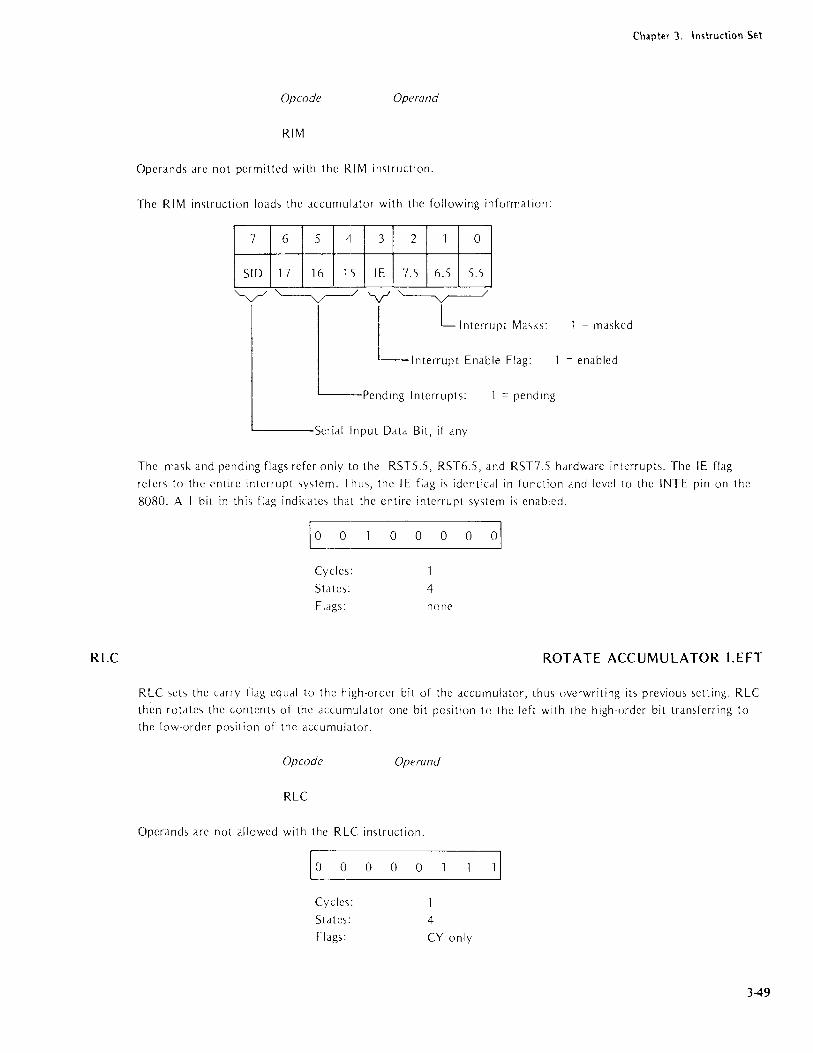
RLC
Opcode Operand
RIM
Operands arc not permitted with the RIM instruction.
The RIM instruction loads the dccumu!:ator with the following information:
~~ ~~ 5
3
IE
2
7.5
1 0
6.5 5.5
"-v-/ ~/ V '----y----/ L L '"Io""pl M,,,'" Interrupt Enable Flag:
-Pending Interrupts: = pending
'------Serial !Input Data Bit, if any
Chapter 3. Instruction Stl
1 = masked
= enabled
The mask and pending flags refer only to the RSTS.S, RST6.S, dnd RST7.S hdrdwdre interrupts. The IE flag
refers to the entire interrupt system. Thus, the IE flag is identical in fur.ction and level to the INTE pin on the
8080. A I bit in this fldg indicates thdt the entire interrupt system i, enabled.
~ 0 0 0 0 01
Cycles: 1
Stdtes: 4 Fldgs: none
ROTATE ACCUMULATOR LEFT
RLC ,ets the Cdrry flag equal to the high-order bit of the accumulator, thus overwriting ib previous setting. RLC
then rotate'> the contents of the accumuldtor one bit position to the left with the high-order bit trdnsferring to
the low-order position of the accumulator.
Opcode Operand
RLC
Operdnds are not allowed with the RLC instruction.
10 0 0 0 0
Cycles:
States:
Flags: 4 CYonly
349

Chapter 3. Instruction Set
RM
3-50
Example:
Assume that the accumulatol' contains the vdlue OAAH and the carry fldg is zero. The following diagrams illus
trate the effect of the RLC Instruction.
Before: Carry
G Accumulator
0 0 ~~ After: Carry
Q Accumulator
10 o o o
RETURN IF MINUS
The RM instruction tests the sign fldg. If the fidg i, set to one to indicate negative data in the dccumulator, the
instruction pops two bytes off the stack and places them in the progrdm counter. Progrdm execution resume, dt
the new dddress in the progl am counter. If the fidg is set to zero, progrdm execution ,imply continues with the
next sequential instruction.
Opcode Operand
RM
Operands are not permitted with the RM instruction.
Example:
1~1 ___________ 0_(~ Cycles:
States:
Ad dressi ng:
Flags:
1 or 3
5 or 11 (6 or 12 on 8085)
register indirect
none
For the sake of brevity, an example is given for the RET instruction but not for each of it> closely related
variants.

RNC
RNZ
Chapter 3. Instruction Set
RETURN IF NO CARRY
The RNC instruction tests the cJrry flag. If the flag is set to zero to indicate that there has been no cJrry, the
in'>truction pops two bytes off the ctack and places them in the program counter. Program execution resumes at
the new address in the program counter. If the flag is one, program execution simply continues with the next sequential in<;truction.
Opcode Operand
RNC
Operand,> are not permitted with the RNC instruction.
o
Cycles:
State',:
Addressing:
Flag'>:
Example:
o 0 0 0\
or 3
5 or 11 (6 or 12 on 8085)
register indirect
none
For the sake of brevity, an example i', given for the RET instruction but not for each of its closely related
varian ts.
RETURN IF NOT ZERO
The RNZ instruction tests the zero flag. If the flag is set to zero to indicate that the contents of the accumulator
are other than lero, the instruction pops two bytes off the stack and places them in the program counter. Pro
gram execution resume, at the new address in the program counter. If the flag is '>et to one, program execution
,imply continue, with the next '>equential imtruction.
Opcode Operand
RNZ
Operand, are not permitted with the RNZ instruction.
Example:
o 0 0 0 0 01
Cycles:
State',:
Addressing:
Flags:
or 3
5 or 11 (6 or 12 on 8085)
register indirect
none
For the ,>ake of brevity, an example i', given for the RET instruction but not for each of its closely related
varian ts.
3-51

Chapter 3. Instruction Set
RP
RPE
3-52
RETURN IF POSITIVE
The RP instruction tests th(' sign flag. If the flag is reset to zero to indicate positive ddta in the accumuldtor,
the instruction pop, two byte'; off the stack and places them in the program counter. Program execution
resumes at the new dddress in the progrdm counter. If the fhg is set to one, progrdm execution simply continues
with the next sequential in5.trunion.
Op co de Operand
RP
Operdnds dre not permitted with the RP instruction.
Cycles:
Std tes:
Addressing:
Fldgs:
Example:
o 0 ~ or 3
5 or 11, (6 or 12 on 8085)
register indirect
none
For the sdke of brevity, an example i, given for the RET irl'>truction but not for each of II'> clo,ely related
vdriants.
RETURN IF PARITY EVEN
Pdrity i, even if the byte in the accumulator has an even number of one bits. The pdrity flag is set to one to
indicate this condition. Thl' RPE dnd RPO imtructiom are useful for testing the parity of input ddtd. However,
the IN instruction does not set any of the condition flag,. The flags Cdn be set without altering the ddta by
ddding OOH to the content'·, of the accumulator.
The RPE imtruction te,ts the parity flag. If the fldg is set 1.0 one to indicate even pdrity, the instruction pops
two byte, off the stack and pldce, them in the progrdm counter. Program execution resumes ,1t the new dddrcS'>
in the program counter. If the fldg is zero, program execut,on simply continue, with the next ,equential imtruc· tion.
Opcode Operand
RPE
Operands are not permitted with the RPE instruction.
I '--1 ___ 0 __ 0_~ Cycles:
Sta tes:
Addre'>5ing:
Flags:
or 3
5 or 11 (6 or 12 on 8085)
register indirect
none

RPO
RRC
Chapter 3. Instruction Set
Example:
For the sake of brevity, an example is given for the RET instruction but not for each of its closely related
varia nts.
RETURN IF PARITY 000
Parity is odd if the byte in the accumulator has an odd number of one bits. The parity flag is reset to zero to
indicate this condition. The RPO and RPE instructions are useful for testing the parity of input data. However,
the IN instruction does not set any of the condition flags. The flags can be set without altering the data by
adding OOH to the contents of the accumulator.
The RPO instruction tests the parity flag. If the flag is reset to zero to indicate odd parity, the instruction pops
two bytes off the stack and places them in the program counter. Program execution resumes at the new addre<,s
in the program counter. If the flag is set to one, program execution simply continues with the next sequential
instruction.
Opcode Operand
RPO
Operands are not permitted with the RPO instruction.
[I 0 0 0 0 3 Cycles: or 3
States: 5 or 11 (6 or 12 on 8085)
/\ddressing: register indirect
Flags: none
Example:
For the sake of brevity, an example is given for the RET instruction but not for each of its closely related
variants.
ROTATE ACCUMULATOR RIGHT
RRC sets the carry flag equal to the low-order bit of the accumulator, thus overwriting its previous setting. RRC
then rotates the contents of the accumulator one bit position to the right with the low-order bit transferring to
the high order position of the accumulator.
Opcode Operand
RRC
Operands are not permitted with the RRC instruction.
3-53
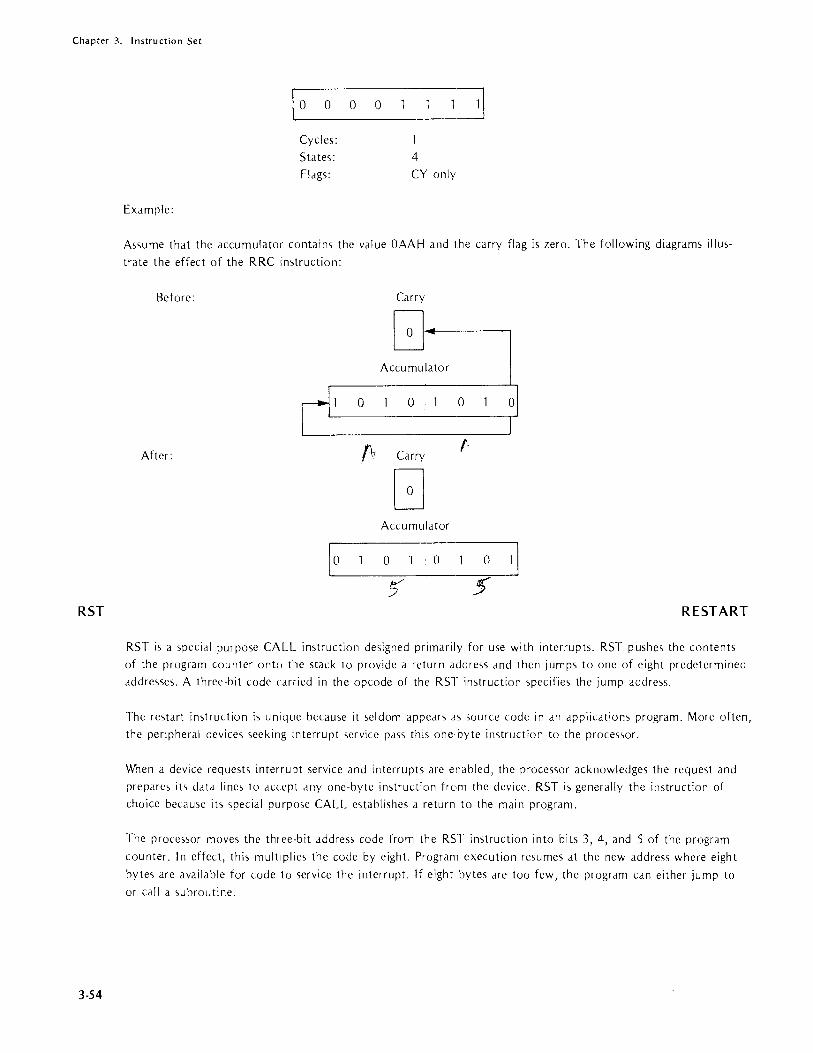
Chapter 3. Instruction Set
RST
3-54
Example:
[_O ___ O ___ O __ O _________ l~ Cycles:
States:
Flags:
1
4 CY only
Assume that the accumulator contains the value OAAH and the carry flag is zero. The following diagrams illus
trate the effect of the RRC instruction:
Before: Carry
G.-Accumulator
r' 0 0 0
After: f\r Carry r
G Accumulator
\~O ______ O _____ O __ ~ 5' 5'
RESTART
RST is a ,pecial purpose CALL instruction designed primarily for use with interrupts. RST pushes the contents
of the program counter ontc) the stack to provide a return address and then jumps to one of eight predetermined
addresses. A three-bit code can-ied in the opcode of the RST instruction specifies the jump address.
The restart instruction is unique because it seldom appears as source code in an applications program. More often,
the peripheral devices seeking interrupt service pass this one·byte instruction to the proces<,or.
When a device reque,ts interrupt service and interrupts are enabled, the processor acknowledges the request and
prepare, it> data line, to accept anyone-byte in,truction frum the device. RST is generally the instruction of
choice because its special purpose CALL establishes a return to the main program.
The proces,or moves the three-bit address code from the RST instruction into bits 3, 4, and 5 of the program
counter. In effect, this multiplies the code by eight. Program execution resumes at the new address where eight
bytes are available for code to service the interrupt. If eight bytes are too few, the program can either jump to
or call a subroutine.
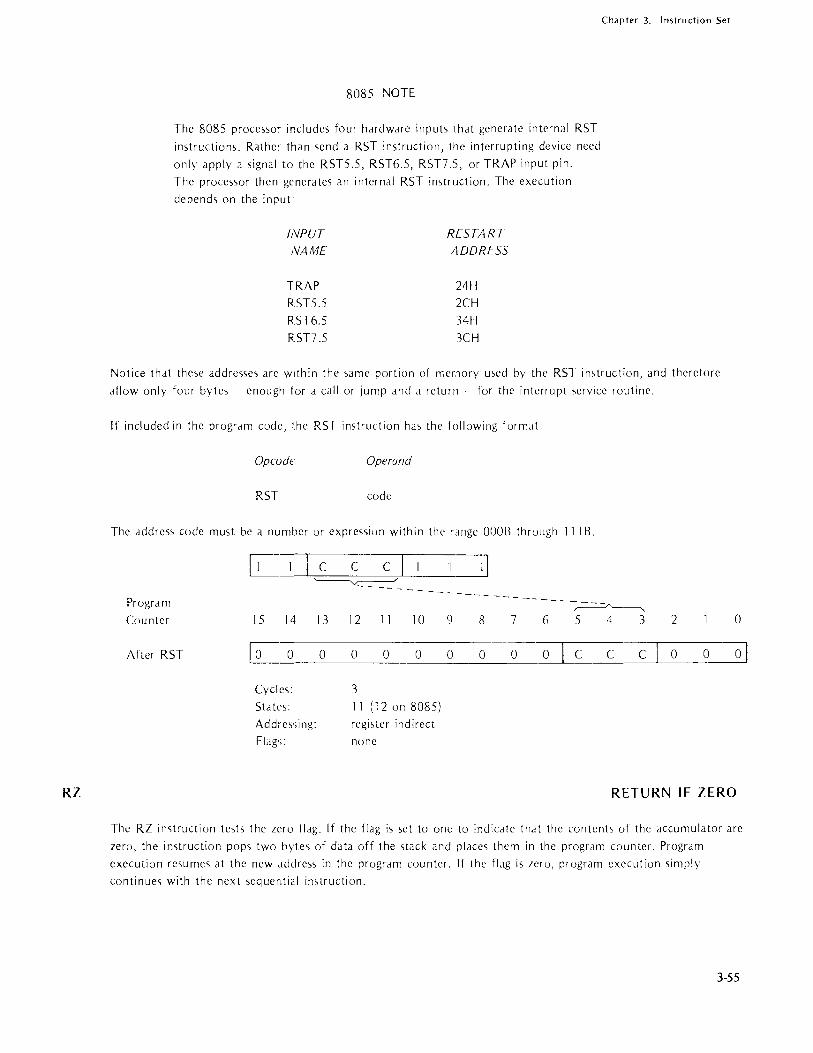
RZ
Chapter 3. Instruction Set
8085 NOTE
The 8085 processor includes four hardware inputs that generate intrrnal RST
instructions. Rather than send a RST instruction, the interrupting device need
only apply a signal to the RST5.5, RST6.5, RST7.S, or TRAP input pin.
The processor then generates an internal RST instruction. The execution
depends on the input
INPUT RESTART NAME ADDRESS
TRAP 24H
RST5.5 2CH
RST6.5 34H
RST7 .5 3CH
Notice that these addre'>ses are within the same portion of rr,ernory u'>ed by the RST instruction, and therefore
allow only four byte'> - enough for a call or jump and a return for the interrupt service routine.
If included in the program code, the RST instruction ha'> the following format:
Opcode Operand
RST code
The addre5'> code must be a number or expre,>,>ion within the range OOOB through 111 B.
1=:3 Progr am ~------. Cou nter 15 14 13 12 11 10 9 8 7 (j 5 4 3 2
After RST Eo 0 0 0 0 0 0 0 0 C C C 0 0
Cycles: 3
Std tes: 11 (12 on 8085)
Addre'>',ing: register indirect
Flag';: none
0
01
RETURN IF ZERO
The RZ imtruction test, the zero flag. If the flag is set to one to indicate that the contents of the accumulator are
zero, the instruction pops two bytes of data off the stack and places them in the program counter. Program
execution resumes at the new address in the program counter. If the flag is zero, program execution simply
continues with the next sequential instruction.
3-55

Chapter 3. Instruction Set
SBB
3-56
Opcode Operand
RZ
Operands are not permitted with the RZ instruction.
o 0
Cycles:
States:
Addressing: Flags:
Example:
o O~ or 3
5 or 11 (6 or 12 on 8085)
register indirect
none
For the sake of brevity, an example is given for the RET instruction but oot for each of its closely related
variants.
SUBTRACT WITH BORROW
SBB subtracts one byte of data and the setting of the carry flag from the contents of the accumulator. The
result is stored in the accumulator. SBB then updates the setting of the carry flag to indicate the outcome of
the operation.
SBB's use of the carry flag enables the program to subtract Ilulti-byte strings. SBB incorporates the carry flag by
adding it to the byte to be subtracted from the accumulator. It then subtracts the result from the accumulator
by using two's complement addition. These preliminary operations occur in the processor's internal work registel
so that the source data remains unchanged.
Subtract Register from Accumulator with Borrow
Opcode Operand
SBB reg
The operand must specify one of the registers A through E, H or L. This instruction subtracts the contents of
the specified register and the carry flag from the accumulator and stores the result in the accumulator.
o 0
Cycles:
States:
Addressing: Flags:
S s3 4 register
Z,S,P,CY,AC

SBI
Chapter 3. Instruction Sel
Subtract Memory from Accumulator with Borrow
Opcode Operand
SBB M
This imtruction subtracts the carry flag and the contents of the memory location addres,>ed by the Hand L
regi'>ters from the accumulatOl" and stores the result In the accumulator.
Example:
1_1 _0 _0 ____ 1 01
Cycles:
States:
Addressing:
Flags:
2 7 register i.1direct
Z,S,P,CY,AC
Assume that register B contains 2, the accumulator contains 4, and the carry flag is set to 1. The instruction
SBB B operate,> as follows:
2H + carry = 3H
2\ complement of 3H = 11111101
Ac:urnulator = 00000100 11111101
00000001 = 1 H
Notice that thi, two\ complement addition produces a carry When SBB complements the carry bit generated
by the ,Iddition, the carry flag is re,et OFF. The flag ,>cttings resulting from the SBB B in,truction arc as
follows:
Carry 0
Sign 0
Zero 0 Parity 0
Aux. Clrry
SUBTRACT IMMEDIATE WITH BORROW
SBI ,uhtract<, the contenb of the second instruction hyte and the ,citing of the carry flag from the contents of
the accumul,ltor. The result i, stored in the accumulator.
SBI.., u,e of the Cdrry flag enables the program to subtract multi·byte ,tring'>. SBI incorpordtes the carry flag by
adding it to the hyte to he subtracted from the accumulator. It then ,ubtrach the result from the accumulator
by u,ing two's complement addition. These preliminary operations occur in the proce'>sor\ internal work regi'>1ers
,0 that the immediate ,OtIrce dilta remaim unchanged.
3-57

Chapter 3. Instruction Set
SHLID
3-58
The assembler's relocation feature treats all external and relocatable symbols as 16-bit addresses. When one of
these symbols appears in the operand expression of an immediate instruction, it must be preceded by either the
HIGH or LOW operator to specify which byte of the address is to be used in the evaluation of the expression.
When neither operator is pre~ent, the a'>sembler assumes the LOW operator and issues an error message.
Opcode Operand
SBI data
The operand mu'>t specify the data to be subtracted. This data may be in the form of a number, an ASCII
constant, the label of some perviously defined value, or an expression. The data may not exceed one byte.
Cycles:
S ta tes:
Addressing:
Flags:
Example:
2 7 immediate
Z,S,P,CY,AC
The following sequence of instruction> enables the program to test the setting of the carry flag:
XRA A 581
The exclusive OR with the accumulator clears the accumulator to zeros but doe,> not affect the setting of the carry flag. (The XRA instruction is explained later in this chapter.) When the carry flag i'> OFF, S81 I yields a minus one. When the flag ,s <,et ON, SBI 1 yields a minus 'woo
NOTE
This eXJmple i'> included for illustrative purposes. In most
ca,e" the carry flag can be tested more efficiently by u'iing
th~ J NC in>truction (jump if no carry).
STORE H AN D L DIRECT
SHLD stores a copy of the 1_ register in the memory location specified in bytes two Jnd three of the SHLD
instruction. SHLD then Stori~S a copy of the H register in the next higher memory location.
Op co de Operand
SHLD address
The address may be stated J'> it number, a previously defined label, or an expression.

Chapter 3. Instruction Set
SHLD is one of the instructions provided for saving the contents of the Hand L registers. Alternately, the H
and L data can be placed in the D and E registers (XCHG instruction) or placed on the stack (PUSH and XTHL
instructions) .
0 0 1 0 0 0 1 0
low addr
high addr
Cycles: 5 States: 16 Addressing: di rect Flags: none
Example:
Assume that the Hand L registers contain OAEH and 29H, respectively. The following is an illustration of the
effect of the SHLD IOAH instruction:
Memory Before SHLD
Memory After SHLD
MEMORY ADD RE
109 lOA
00 00
00 29
10
0
B
o AE
SS
IOC 00
00
SIM (81085 PROCESSOR ONLY) SET INTERRUPT MASK
SIM is a multi-purpose instruction that uses the current contents of the accumulator to perform the following
functions: Set the interrupt mask for the 8085's RST5.5, RST6.5, and RST7.5 hardware interrupts; reset
RST7.5'<, edge sensitive input; Ind output bit 7 of the accumulator to the Serial Output Data latch.
Operand
SIM
Operands are not permitted wi'h the SIM instruction. However, you must be certain to load the desired bit configurations into the accumulator before executing the SIM instruction. SIM interprets the bits in the accumu· lator as follows:
3-59

Chapter 3. Instruction Set
3-60
v
L{ RSn.S MASK
RST6.S MASK
RSTS.S MASK {
o = available
1 = masked
flf 0, bits 0 .. 2 ignored
Mask Set Enable \If 1, mask is set
RESET RSn.S: If 1, RSn.S flip flop is reset OFF
ignored
If 1, bit 7 is ou tput to Serial Output Data Latch Serial Output Data: ignored if bit 6 = 0
Accumulator bits 3 and 6 fUllction as enable switches. If bit 3 is set ON (set to 1), the set mask function is
enabled. Bits 0 through 2 then mask or leave available the corresponding RST interrupt. A 1 bit masks the
interrupt making it unavailable; a 0 bit leaves the interrupt available. If bit 3 is set OFF (reset to 0), bits 0
through 2 have no effect. Usc this option when you want L) send a serial output bit without affecting the
interrupt mask.
Notice that the 01 (Disable Interrupts) instruction overrides the SI M instruction. Whether masked or not, RSTS.S,
RST6.S, and RST7.S are disdblcd when the 01 instruction i'> in effect. Use the RIM (Read Interrupt Ma,k)
instruction to determine the current setting'> of the interrupt flag and the interrupt mdsks.
If bit 6 is ,et to 1, the serial output datd function is enabled. The processor Idtche'> dccumuldtor bit 7 into the
SOD output where it can be accessed by a peripheral device. If bit 6 is re,et to 0, bit 7 is ignored.
A 1 in accumulator bit 4 res.?ts OFF the RST7.S input flip flop. Unlike RSTS.S dnd 6.S, RST7.S is '>ensed Vld a
processor flip flop that is set when a peripheral device issues d pulse with a rising edge. This edge triggered input
supports devices that cannot maintain an interrupt request until serviced. RST7.S is also u'>eful when a device
does not require any explicit hardware service for each interrupt. For example, the program might increment and
test an event cou nter for each interrupt rather than service the device directly.
The RST7.S flip flop remains set l.Intil reset by 1) issuing a RESET to the 808S, 2) recogni/ing the interrupt, or
3) setting accumulator bit 4 and executing a SIM instruction. The Reset RST7.S feature of the SIM instruction
allows the program to override the interrupt.
The RST7.S input flip flop is not affected by the setting of the interrupt mask or the 01 instruction and there·
fore can be set at any time. However, the interrupt cannot be ,erviced when RST7.S is masked or d 01 instruction
is in effect.
10 0
Cycles:
States:
Flags:
o 0 c~ 1
4 none
Example 1: Assume that the accumulator contains the bit pattern 00011100. The SIM instruction resets the
RST7.S flip flop and sets the RST7.S interrupt mask. If an RST7.S interrupt i'> pending when this SI M instructio
is executed, it is overridden without being serviced. Also, anv subsequent RST7.S interrupt is masked and cannot
be serviced until the interrupt mask is reset.

SPHL
STA
Chapter 3. Instruction Set
Example 2: Assume that the accumulator contains the bit pdttern 11001111. The SI M instruction masks out the
RST5.5, RST6.5, dnd RST7.S level interrupts and latches a 1 bit into the SOD input. By contrast, the bit pattern
10000111 has no effect since the enable bits 3 and 6 are not set to ones.
MOVE H& L TO SP
SPHL 10dds the contents of li1C Hand L registers into the SP (Stack Pointer) register.
Operand
SPHL
Operands are not permitted with the SPHL instruction.
SP is a special purpose 16-bit register used to address the stack; the stack must be in random access memory
(RAM). Because different applications use different memory configurations, the user program must load the SP
register with the suck'., beginning address. The stack is usually a'>signed to the highest dvailable location in RAM.
The hardware decrements the stack pointer as items are ddded to the stdck and increments the pointer as items
are removed.
The stdck pointer must be initialized before dny instruction attempts to access the <,tack. Typically, stack
initialization occurs very early in the program. Once estdbli,hed, the stack pointer should be altered with
caution. Arbitrary use of SPHL can cause the loss of stdck ddtd.
Example:
[_1 ____ 0_03
Cycles:
Sta tes:
Addressing:
Flags:
5 (6 on 8085)
register
none
A'>sume that the H dnd L registers contain 50H and OFFH, respectively. SPHL IOdds the stack pointer with the
vdlue 50FFH.
STORE ACCUMULATOR DIRECT
STA stores d copy of the current dccumuldtor contents intu the memory location srecified in bytes two and
three of the STA instruction.
Ope ode Operand
ST}, address
The address may be stated as d number, a previously defined label, or <in expression. The ds~embler inverts the
high dnd low dddress bytes when it builds the instruction.
3-61

Chaptl'r 3. Instruction Set
STAX
3-62
0 0 1 1 0 0 1 0
low addr
high addr
Cycles: 4
States: l3
Addressing: direct
Flags: none
Example:
The following instruction stores a copy of the contents of the accumulator at memory location SB3H:
STA SB3H
When assembled, the previous instruction has the hexadecimal value 32 B3 05. Notice that the assembler inverts the high and low order addr·ess bytes for proper storage in memory.
STORE ACCUMULATOR INDIRECT
The STAX instruction stores a copy of the contents of the accumulator into the memory location addressed
by register pair B or register pair D.
Opcode Operand
STAX
The operand B specifies the Band C register pair; D specifies the D and E register pair. This instruction may
specify only the B or D register pair.
Example:
10001 10 0 ~
Cycles: States:
Addressing:
Flags:
'-v-"
l{o = register pair B 1 = register pair D
2 7 register indirect
none
If register B contains 3FH .and register C contains 16H, the following instruction stores a copy of the contents
of the accumulator at memory location 3F16H:
STAX B

STC
SUB
STC sets the Cdrry flag to one. No other flags arc affected.
Opcode Operand
STC
Operands arc not permitted '.Ivith the STC instruction.
\0 0
Cycles:
States:
Flags:
o
4 Cy
Chapter 3. Instruction Set
SET CARRY
When u'>ed in combination with the rotate accumulator through the carry flag in'>tructions, STC allows the pro
gram to modify individudl bits.
SUBTRACT
The SUB in<,truction subtrac1s one byte of data from the contents of the accumulator. The result is stored in the
accullluLltor. SUB u'>('s two"> complement representation of data as explained in Chapter 2. Notice that the SUB
ill'>tructioll excludes the Cdrrv flag (actually a 'borrow' flag for the purposes of subtraction) but sets the flag to
indicate the outcome of the :>peration.
Subtract Register from Accumulator
Opcode Operand
SUB reg
The operands mu,t specifY O;le of the registers A through E, H or L. The imtruction subtr.lcts the contents of
the '>pecified regi,ter from the contents of the accumuldtor using two\ complement data representation. The
re'>ult is stored in the accumulator.
o 0 o S ~ Cycles:
States: 4
Addressing: register
Flag.,: Z ,S ,P ,CY ,AC
Subtract Memory from Accumulator
Opcode Operand
SU8 M
3-63

Chapter 3. Instruction Set
SUI
3·64
This instruction subtracts the contents of the memory location addressed by the Hand L registers from the
contents of the accumulator and stores the result in the accumulator. M is a symbolic reference to the Hand L
registers.
~11 ___ 0 ___ 0 ______ 0 ______ 1 ~ Cycles: States: Addressing: Flags:
Example:
2 7 register indirect Z,S,P,CY,AC
Assume that the accumulator contains 3EH. The instruction SUB A subtracts the contents of the accumulator
from the accumulator and produces a result of zero as follows:
3EH +(-3EH)
carry out = 1
00111110
11000001
1
00000000
The condition flags are set as follows:
Carry
Sign
Zero Parity
Aux. Carry
one's complement
add one to produce two's complement
result = 0
o o
Notice that the SUB in>truction complements the carry generated by the two's complement addition to form a 'borrow' flag. The auxiliary carry flag is set because the particular value used in this example causes a carry out of bit 3.
SUBTRACT IMMEDIATE
SUI subtracts the contents of the second instruction byte from the contents of the accumulator and stores the
result in the accumulator. Notice that the SUI instruction di5.regards the carry ('borrow') flag during the sub
traction but sets the flag to indicate the outcome of the operation.
Opcode Operand
SUI data
The operand must specify the data to be subtracted. This data may be in the form of a number, an ASCII
constant, the label of some previously defined value, or an expression. The data must not exceed one byte.
The assembler's relocation feature treats all external and relocatable symbols as 16-bit addresses. When one of
these symbols appears in the operand expression of an immediate instruction, it must be preceded by either the

XCH<:;
Chapter 3. Instruction Set
HIGH or LOW operator to specify which byte of the address is to be used in the evaluation of the expression.
When neither operator is present, the assembler assumes the LOW operator and issues an error message.
a
Cycles:
Sta tes:
Addressing:
Flags:
Example:
a a
2
7
immediate
Z,S,P,CY,AC
Assume that the accumulator contains the value 9 when the instruction SUI 1 is executed:
;\c(umulator
I Tlrnediate data (2'5 camp)
00001001 = 9H
11111111 =-lH
00001000 = 8H
Notice that this two's complement addition results in a carry. The SUI instruction complements the carry
generated by the addition to form a 'borrow' flag. The flag settings r'esulting from this operation are as follows:
Carry a Sign a Zero a Parity a f\UX. Carry
EXCHANGE HAND L WITH D AND E
XCHG exchange~ the content', of the Hand L registers with the contents of the D and E registers.
Op co de Operand
XCHG
Operand, are not allowed with the XCHG instruction.
XCHG both saves the current Hand L and load" a new addre.,., into the Hand L register' •. Since XCHG i" a
register·to·regi,tcr instruction, it provides the quickest means of saving and/or altering the Hand L registers.
Cycles:
Sta tes:
Addressing:
Flags:
a a
4
register
none
3-65

Chapter 3. Instruction Set
XRA
3-66
Example:
Assume that the Hand L registers contain 1234H, and the D and E registers contain OABCDH. Following
execution of the XCHG instruction, Hand L contain OABCDH, and D and E contain 1234H.
EXCLUSIVE OR WITH ACCUMULATOR
XRA performs an exclusive OR logical operation using the contents of the specified byte and the accumulator.
The result is pldced in the accumulator.
Summary of Logical Operations
AND produces a one bit in the I"esult only when the corresponding bits in the test data and the mask data are
ones.
OR produces a one bit in the result when the corresponding bits in either the test data or the mask data are
ones.
Exclusive OR produces a one bit only when the corresponding bits in the test data and the mask data are different; i.e., a one bit in either the test data or the mask data -- but not both - produces a one bit in the resu I t.
AND
1010 1010
0000 1111 0000 1010
XRA Register with Accumulator
Opcode
XRA
OR
1010 1010 0000 1111
1010 1111
Operand
reg
EXCLUSIVE OR
10101010 0000 1111
10100101
The operand must specify one of the registers A through E, H or L. This instruction performs an exclusive OR
using the contents of the specified register and the accumuldtor and stores the result in the accumulator. The
carry and auxiliary carry flags are reset to zero.
o
Cycles: States:
Addressing: Flags:
o S S~
4
regis ter
Z,S,P,CY,AC

XRI
Chapter 3. Instruction Set
XRA Memory with Accumulator
Opcode Operand
XRA M
The contents of the memory location specified by the Hand L registers is exclusive-ORed with the contents of
the accumulator. The result is stored in the accumulator. The carry and auxiliary carry flags are reset to zero.
Examples:
[_1 _O __ O ___ .~ Cycles:
S ta tes:
Ad dressing:
Flags:
2
7 register indirect
Z,S,P,CY,AC
Since any bit exclusive-ORed with itself produces zero, XRA is frequently used to zero the accumulator. The
following instructions zero the accumulator and the Band C registers.
XRA A
MOV B,A
MOV C,A
Any bit exclusive·ORed with a one bit is complemented. Thus, if the ,lccumulator contains all one~ (OFFH),
the instruction XRA B produce', the one's complement of the B register in the accumulator
EXCLUSIVE OR IMMEDIATE WITH ACCUMULATOR
XRI performs an exclusive OR operation using the contenb of the second instruction byte ,1Ild the contents of
the accumulator. The result is placed in the accumulator. XRI also resets the carry dnd auxiliary carry flags to
zero.
Opcode Operand
XRI data
The operand must specify the data to be used in the OR operation. This data may be in the form of a number,
an ASCII constant, the label of some previously defined value, or an expression. The data may not exceed one
byte.
The assembler's relocation feature treats all external and relocatable symboh as 16-bit addresse'>. When one of
these symbols appears in the operand expression of an immediate instruction, it must be preceded by either the
HIGH or LOW operator to specify which byte of the address is to be used in the evaluation of the expression.
When neither operator is present, the assembler assumes the LOW operator and issues an error message.
3-67

Chapter 3. Instruction Set
3-68
1---0_1~ data ~
Cycles:
States:
Addressing:
Flags:
2
7 immediate
Z,S,P,CY,AC
Summary of Logical Operations
AND produces a one bit in the result only when the corresponding bits in the test data and the mask data are
ones.
OR produces a one bit in the result when the corresponding bit~ in either the test data or the mask datd dre
ones.
Exclusive OR produces a one bit only when the corresponding bits in the test data dnd the mask datd are
different; i.e., a one bit in either the test data or the mask data ~ but not both produces a one bit in the
resu I t.
Example:
AND
1010101lO 0000 1111
0000 1010
OR
10101010 00001111 1010 1111
EXCLUSIVE OR
10101010 0000 1111 1010 0101
Assume that a program uses bits 7 and 6 of a byte as flags that control the cdlling of two subroutines. The
program tests the bits by rotdting the contents of the accumulator until the de'>ired bit is in the Cdrry fldg; a
CC instruction (Call if Carry) tests the flag and calls the subroutine if required.
Assume that the control flag byte i~ positioned normally in the accumulator, and the program must <,et OFF hit
6 and ~et bit 7 ON. The remaining bits, which are status flag'; used for other purposes, must not be ,litered.
Since any bit exciusive-ORed with a one is complemented, and any bit exciusive-ORed with a zero remdins
unchanged, the following instruction is used:
XRI
The instruction has the following results:
Accumulator
Immediate data
11000000B
01001100 11000000
10001100

XTHL
Chapter 3. Instruction Set
EXCHANGE H&L WITH TOP OF STACK
XTHL exchanges two bytes from the top of the stack with the two bytes stored in the H dnd L registers. Thus,
XTHL both saves the current contents of the Hand L registers and loads new values into Hand L.
Opcode Operand
XTHL
Operands are not allowed with the XTHL instruction.
XTHL exchanges the contents of the L register with the contents of the memory location specified by the SP
(Stack Pointer) register. The contents of the H register are exchanged with the contents of SP+1.
Cycles:
States:
Addressing:
Flags:
Example:
o 0 0 I I 5 18 (16 on 8085)
register indirect
none
Assume that the ~tdck pointer register contains 1 OADH; register H contains OBH dnd L contains 3CH; and
memory locations 10ADH and 10AEH contain FOH and ODH, respectively. The following i'; dn illustrdtion of
the effect of the XTHL instruction:
Before XTHL
After XTHL
10AC
FF
FF
MEMORY ADDRESS
lOAD 10AE
FO 00
3C 08
H L
lOAF
FF OB 3C
FF 00 Fe
The stack pointer register remains unchanged following execution of the XTHL instruction.
Hi9


4. ASSEMBLER DIRECTIVES
This chapter describes the il'isembler directives used to control the 8080/85 assembler in its generation of object
code. This chapter excludes the macro directives, which are discussed as a separate topic in Chapter 5.
Generally, directives have the same format as instructions and can be interspersed throughout your program.
Assembler directives discussed in this chapter are grouped as follows:
GENERAL DIRECTIVES:
• Symbol Definition
EQU
SET
• Data Definition
DB DW
• Memory Reservation
DS
• Conditional Assembly
IF
ELSE
ENDIF
• Assembler Termination
END
LOCATION COUNTER COI\JTROL AND RELOCATION:
• Location Counter Control
ASEG DSEG CSEG ORG
• Program Linkage
PUBLIC
EXTRN
NAME
STKLN
4-1
Chapter 4. Assembler Directives
Three assembler directives· E.QU, SET, and MACRO -- have a slightly different format from assembly
language instructions. The EQU, SET, and MACRO directives require a name for the symbol or macro being
defined to be present in the label field. Names differ from labels in that they must not be terminated with a
colon (:) as labels arc. Also, the LOCAL and ENDM directive', prohibit the usc of the label field.
The MACRO, ENDM, and LOCAL directives are explained in Chapter 5.
SYMBOL DEFINITION
The assembler automatically assigns values to symbols that appear as instruction labels. This value is the current
setting of the location counter when the instruction is assembled. (The location counters arc explained under
'Address Control and Relocation,' later in this chapter.)
You may define other symbols and assign them values by using the EQU and SET directives. Symbols defined
using EQU cannot be redefined during assembly; those defined by SET can be assigned new values by subsequent
SET directive.,.
The name required In the label field of an EQU or SET directive must not be terminated with a colon.
Symbol> defined by EQU dnd SET have meaning throughout the remainder of the program. This may cause the
symbol to have illegal multiple definitions when the EQU or SET directive appears in a macro definition. Usc
the LOCAL directive (described in Chapter 5) to avoid this problem.
EQU Directive
4-2
EQU a.,signs the value of 'expression' to the name specified in the label field.
Label Opcode Operand
name EQU expres.,ion
The required name in the label Field may not be terminated with a colon. This name cannot be redefined by a
subsequent EQU or SET diret.:tive. The EQU expression cannot contain any external .,ymbo!. (External .,ymbols
are explained under 'Location Counter Control and Relocation,' later in this chapter.)
As.,embly-time evaluation of EQU expres.,ions always generate., a modulo 64K address. Thu5, the expression
always yields a value in the rclnge 0-65,536.
Example:
The following EQU directive enters the name ONES into the .,ymbol uble and as,igns the binary value
1111 1111 to it:
ONES EQU OFFH

Chapter 4. Assembler Directives
The value assigned by the EQU directive can be recalled in subsequent source lines by referr'ing to its dssigned
name as in the following IF directive:
IF TYPE EQ ONES
ENDIF
SET Directive
SET as,>igns the value of 'expre~si()n' to the name specified In the label field.
Label Opcode Operand
name SET
The assembler enters the vdlue of 'expression' into the symbol table. Whenever 'ndmc' is encountered sub
sequently in the dssembly, the ""sembler substitutes its vdlue from the .,ymbol tdble. This value remain<; unchdnged
until dltered by a ,1Ih,equent SET directive.
The function of the SET directive is identicdl to EQU except thdt 'name' Cdn appCdr in multiple SET directives
In the same plogrdm. Therefore, you Cdll alter the vdlue a,signed to 'name' throughout the d'>sembly.
A,sembly-time evaludtion of SET expression<; always getlCldte'i d modulo 64K addre',',. ThLlS, the expre'>"ion
dlwdY'> yield,> a value in the rdllge 0-65,536.
Lahel Opcode Operand /Issembled Code
IMMED SET 5 ADI IMMED (605
IMMED SET lOH-6
ADI IMMED (60A
DATA DEFIN ITION
The DB (define byte) and DW (define word) directives enable you to define data to be <;tored In your program.
Data can be specified in the form of 8-bit or 16-bit values, or ' s a stl'ing of text characters.
DB Dirflctive
The DB directive stores the specified data in consecutive memory locations starting with the current setting of the
location counter.
4-3

Chapter 4. Assembler Directives
Label Opcode Operands
optional: DB expression(s) or string(s)
The operand field of the DB directive can contain a list of expressions and/or text strings. The list can contain
up to eight total items; list items must be separated by commas. Because of limited workspace, the assembler
may not be able to handle a total of eight items when the list includes a number of complex expressions. If
you ever have this problem, it is easily solved: simply use two or more directives to shorten the list.
Expressions must evalua te to l-byte (8-bit) numbers in the I-ange ~ 256 through 255. Text strings may comprise a maximum of 128 ASCII characters enclosed in quotes.
The assembler's relocation feature treats all external and relocatable symbols as 16-bit addresses. When one of
these symbols appears in an operand expression of the DB directive, it must be preceded by either the HIGH or
LOW operator to specify which byte of the address is to be used in the evaluation of the expression. When
neither operator is present, the assembler assumes the LOW operator and issues an error message.
If the optional label is present, it is assigned the starting value of the location counter, and thus references the first byte stored by the DB directive. Therefore, the label STR in the following examples refers to the letter T of the string TIME.
Examples:
Label Opcode Operands Assembled Code
STR: DB TIME' 54494D45
HERE: DB OA3H A3
WORD1: DB ~03H,5*2 FDOA
DW Directive
4-4
The DW directive stores each 16-bit value from the expression list as an address. The values are stored starting
at the current setting of the location counter.
Label Opcode Operands
optional: DW expression list
The least significant eight bits of the first value in the expression list are stored at the current setting of the location counter; the most significant eight bits are stored at the next higher location. This process is repeated for each item in the expression list.
Expressions evaluate to 1 ~word (16-bit) numbers, typically addresses. If an expression evaluates to a single byte, it is assumed to be the low order byte of a 16-bit word where the high order byte is all zeros.

Chapter 4. Assembler Directives
List items must be separated by commas. The list can contain up to eight total item,. Bec.Ju,e of limited work
space, the assembler may not be able to handle eight complex expression,. If you ever havc this problem, ,imply
use two or more OW directive, to shorten the list.
The reversed order for slLOring the high and low order bytes is the typical format for addrc''ies stored In memory.
Thus, the OW directive is commonly used for storing address constants,
Strings containing one or two ASCII characters enclmed in quotation marK> may <11,0 appcar In the expression
list. When using such strings in your program, remember that the chJJ"acter's are storcd in reversed order.
Specifying a string longer thdn two characters cau,es an error.
If the optional label is present, it is assigned the starling address of the location counter, and thus references the
first byte ,tored by the OW directive. (This is the low order byte of the first item in the expression Ii,!.)
Examplcs:
Assu me that COM P and F ILL arc label, defined elsewhere in the program, COM P addre))e~. memory location
3B1CH. FILL addresses memory location 3EB4H,
Label Opcode Operands Assembled Code
AODR 1 . OW COMP 1C3B
AODR2 OW FILL B43E
STRNG OW 'A','AB' 41004241
FOUR: DW 4H 0400
MEMORY RESERVATION
DS Directive
The OS directive can be used to define a block of storage.
Label Opcode Operand
optional: OS expression
The value of 'expre'>sion' specifie, the number of byte, to be reserved for data stordge. In theory, this value may
range from OOH through OFFFFH; in practice, you will re',erve no more '>torage than will fit in your availdble
memory and still leave room for the program.
Any ,ymbol appearing in the operand expression must be defined before the a,sembler reaches the OS directive.
Unlike the DB and OW ciirectives, OS assembles no ciata into your program. The content<. of the reserved storage
are unpredictable when program execution is initiated.
4-5

Chapter 4. Assembler Directives
If the optional label is present, it is assigned the current value of the location counter, and thus references the
first byte of the reserved memory block.
If the value of the operand expression is zero, no memory is reserved. However, if the optional label is present,
it is assigned the current value of the location counter.
The OS directive reserves memory by incrementing the location counter by the value of the operand expression.
Example:
TIVBUF: OS 72 ;RESERVE 72 BVTES FOR ;A TERMINAL OUTPUT BUFFER
Programming Tips: Data Description and Access
4-6
I?andom Access Versus Read Only Memory
When coding data descriptions, keep in mind the mix of ROM and RAM in your application.
Generally, the DB and OW directives define constants, items that can be assigned to ROM. Vou can use the~e
items in your program, but you cannot modify them. If these items are assigned to RAM, they have an initial
value that your program can ,modify during execution. Notice, however, that the,e initial values must be reloaded
into memory prior to each execution of the program.
Variable data in memory must be assigned to RAM.
Data Description
Before coding your program, you must have a thorough understanding of its input and output data. But you'll
probably find it more convenient to postpone coding the data descriptions until the remainder of the program is fairly well developed. This way you will have a better idea of the constants and workareas needed in your program. Also, the organization of a typical program places instructions in lower memory, followed by the data, followed
by the stack.
Data Access
Accessing data from memory i, typically a two-step process: First you tell the processor where to find the data,
then the processor fetches the data from memory and loads it into a register, usually the accumulator. Therefore,
the following code sequences have the identical effect of loading the ASCII character A into the accumulator.
AAA: DB 'A'
LXI B,AAA
LDAX B
ALPHA: DB
LXI
LDAX
'ABC'
B,ALPHA
B

Chapter 4. Assembler Directives
In the examples, the LXI instructions load the address of the desired data into the Band C registers. The LDAX
instructions then load the accumulator with one byte of data from the address specified in the Band C registers.
The assernbler neither knows nor cares that only one character from the three-character field ALPHA has been
accessed. The program must account for the characters at ALPHA+l and ALPHA+2, as in the following coding
sequence:
ALPHA: DB 'ABC' ;DEFINE ALPHA
LXI B,ALPHA ;LOAD ADDRESS OF ALPHA
LDAX B ;FETCH 1 ST ALPHA CHAR
INX B ;SET B TO ALPHA+l LDAX B ;FETCH 2ND ALPHA CHAR
INX B ;SET B TO ALPHA+2
LDAX B ;FETCH 3RD ALPHA CHAR
The coding above is acceptable for short data fields like ALPHA. For longer fields, you can conserve memory
by setting up an instruction sequence that is executed repeatedly until the source data is exhausted.
Add Symbols for Data Access
The following example was presented earlier as an illu5tration of the OS directive:
Label Opcode Operand Comment
TTYBUF: OS 72 ;RESERVE TTY BUFFER
To access data in this buffer using only expressions such as TTYBUF+l, TTYBUF+2, ... TTYBUF+72 can be
a laborious and confusing chore, especially when you want only selected fields from the buffer. You can simplify this task by subdividing the buffer with the EQU directive:
Label Opcode Operand Comment
TIYBUF: OS 72 ;RESERVE TTY BUFFER
10 EQU TTYBUF ;RECORD IDENTIFIER
NAME EQU TTYBUF+6 ;20-CHAR NAME FIELD
NUMBER EQU TTYBUF+26 ;10-0-lAR EMPLOYEE NUMBER
DEPT EQU TTYBUF+36 ;5-CHAR DEPARTMENT NUMBER
SSNO EQU TTYBUF+41 ;SOCIAL SEC. NUMBER
DOH EQU TTYBUF+50 ;DATE OF HIRE
DESC EQU TTYBUF+56 ;)OB DESCRIPTION
4-7

Chapter 4. Assembler Directives
Subdividing data as shown in the example simplifies data access and provides useful documentation throughout
your program. Notice that these EQU directives can be inserted anywhere within the program as you need them,
but coding them as shown in the example provides a more useful record description.
CONDITIONAL ASSEMBLY
The IF, ELSE, and ENDIF directives enable you to assemble portions of your program conditionally, that is,
only if certain cond itions th,lt you specify are sa tisfied.
Conditional assembly is especially useful when your application requires custom programs for a number of com
mon options. As an example, assume that a basic control program requires customizing to accept input from
one of six different sensing devices and to drive one of five different control devices. Rather than code some
thirty separate programs to account for all the possibilities, you can code a single program. The code for the in
dividual sensors and drivers must be enclosed by the conditional directives. When you need to generate a custom
program, you can insert SET directives near the beginning of the source program to select the desired sensor and
driver routines.
IF, !ELSE, ENDIF Directives
4-8
Because these directives are used in conjunction, they are described together here.
Label Opcode Operand
optional: IF expression
optional: ELSE
optional: ENDIF
The assembler evaluates the expression in the operand field of the IF directive. If bit 0 of the resulting value is
one (TRUE), all instruction'; between the IF directive and the next ELSE or ENDIF directive are assembled.
When bit 0 is zero (FALSE) these instructions are ignored. (A TRUE expression evaluates to OFFFFH and
FALSE to OH; only bit zero need be tested.)
All statements included between an IF directive and its required associated ENDIF directive are defined as an
IF·ENDIF block. The ELSE directive is optional, and only one ELSE directive may appear in an IF-ENDIF
block. When included, ELSE is the converse of IF. When bit 0 of the expression in the IF directive is zero, all
statements between ELSE and the next ENDIF are assembled. If bit 0 is one, these statements are ignored.
Operands are not allowed with the ELSE and ENDIF directives.
An IF-ENDIF block may appear within another IF·ENDIF block. These blocks can be nested to eight levels.
Macro definitions (explained in the next chapter) may appear within an IF·ENDIF block. Conversely, IF-ENDIF
blocks may appear within macro definitions. In either case, you must be certain to terminate the macro definition

Chapter 4. Assembler Directives
or IF-ENOl F block so that it can be assembled completely. For example, when a macro definition begins in an
I F block but terminates after an ELSE directive, only a portion of the macro can be assembled. Similarly, an
I F-ENDIF block begun within a macro definition must terminate within that same macro definition.
NOTE
Caution is required when symbols are defined in IF-ENDIF blocks and referenced elsewhere within the program. These
symbols are undefined when the evaluation of the IF expression suppresse,> the assembly of the IF-ENDIF block.
Example 1. Simple IF-ENDIF Block:
COND1: IF TYPE EQ 0
ENDIF
Example 2. IF-ELSE-Er~DIF Block:
COND2: IF TYPE EQ 0
ELSE
ENDIF
;ASSEMBLED IF 'TYPE = 0'
;IS TRUE
;ASSEMBLED IF 'TYPE = O·
;IS TRUE
;ASSEMBLED IF 'TYPE = O· ;IS FALSE
4-9

Chapter 4. Assembler Directives
Example 3. Nested IF's:
COND3: IF TYPE EO 0
;ASSEMBLED IF 'TYPE = 0'
;IS TRUE
IF MODE EO 1
LEVEL ;ASSEMBLED IF 'TYPE = 0'
;AND 'MODE = l' ARE BOTH
;TRUE
ENDIF
ELSE
LEVEL ;ASSEMBLED IF 'TYPE = 0'
2 ;IS FALSE
IF MODE EO 2
;ASSEMBLED IF 'TYPE = 0'
;IS FALSE AND 'MODE = 2'
;IS TRUE LEVEL ELSE
;ASSEMBLED IF 'TYPE = 0' ;AND 'MODE = 2' ARE BOTH ;FALSE
ENDIF
ENDIF
ASSEMBLER TERMINATION
END Directive
4-10
The END directive identifies the end of the source program and terminates each pass of the assembler.
Label Opcode Operand
optional: END expression
Only one END statement ma)! appear in a source program, and it must be the last source statement.
If the optional expression is present, its value is used as the starting address for program execution. If no ex
pression is given, the assembler assumes zero as the starting address.
When a number of separate program modules are to be joined together, only one may specify a program ~tarting address. The module with a starting address is the main module. When source files are combined using the INCLUDE control, there are no restrictions on which source file contains the END.

Chapter 4. Assembler Directives
END-OF-TAPE INDICATION
The EOT directive allows you to specify the physical end of paper tape to simplify assembly of multiple-tape source
programs.
EOT Directive
Label Opcode Operand
optional: EOT
When EOT is recognized by the assembler, the message 'NEXT TAPE' is sent to the console and the assembler pauses.
After the next tape is loaded, a 'space bar' character received at the console signals continuation of the assembly.
Data in the operand field caU5.es an error.
LOCATION COUNTER CONTROL AND RELOCATION
All the directives discussed in the remainder of this chapter relate directly to program relocation except for the
ASEG and ORG directives. These directives are described first for the convenience of readers who do not use the
relocation feature.
Location Counter Control (Non-Re·locatable Mode)
When you elect not to use the relocation feature, an assembler default generate, an ASEG directive for you. The
ASEG directive specifies that the program is to be assembled in the non-relocatable mode dnd cstablishe, a
location counter for the assembly.
The location counter performs the same function for the assembler as the program counter performs during
execution. It tells the as',emblel- the next memory location availdble for in'>truction or data assembly.
Initially, the location countel- i:; set to Lero. The location counter can be altered by the ORG (origin) directive.
ORG Directive
The ORG directive sets the location counter to the value specified by the operand expre'>sion.
Label Opcode Operand
optional: ORG expression
The location counter is ',et to the value of the operand expre,sion. Assembly-time evaluation of ORG expressions
always yields a modulo 64K address. Thus, the expression always yield, an address in the range 0 through
65,535. Any symbol in the expression must be previously defined. The next machine instruction or data item is
assembled at the specified address.
4-11

Chapter 4. Assembler Directives
If no ORG directive is included before the first imtruction or data byte in your program, assembly begins at
location zero.
Your program can include any number of ORG directives. Multiple ORG's need not specify addresse,> in
ascending ,equence, but if you fail to do so, you may instruct the assembler to write over some previously
a'>5embled portion of the program.
If the optional label is present, it is a,signed the current value of the location counter before it is updated by the
ORG directive.
Example:
Assume that the current value of the location counter is OFH (decimal 15) when the following ORG directive is
encou n tered :
PAG1: ORC OFFH ;ORG ASSEMBLER TO LOCATION
;OFFH (decimal 225)
The symbol PAG 1 is assigned the addl'es'i OFH. The next instruction or data byte is assembled at location
OFFH.
Introduction to Relocatability
4-12
A major feature of thi, assembler i'> ih system for creating relocatable object code modules. Support for this new
feature include,> a number of !lew directives for the a'>5embler and three new program'> included in ISIS·II. The
three new programs LIB, LINK, and LOCATE arc de,>cribed in the ISIS·II System User'., Guide. The new
assembler directives arc described later in this chapter.
lRelocatability allows the prograrnmer to code programs or '>ections of rrograms without worrying about the
final arrangement of the object code in memory. Thi, offers developer,> of microcomputer systems major ad·
vantage'> in two areas: memol y management and modulal' program development.
Memory Management
When developing, testing, and debugging a system on your Intellec miclocomputer development system, your
only concern with locating a program i, that it doesn't overlap the resident routines of ISIS·II. Because the
I:ntellec system has 32K, 48K, or 64K of random acce", memory, the loc,ltion of your future program i, not a
great concern. However, the p'ogram you arc developing will ,{Immt certainly u,e ,orne mix of random dCCe'iS
memory (RAM), read·only memory (ROM), and/or programmable reaclonly memory (PROM). Therefore, the
location of your program affech both cost and performance iii your application. The relocaLlbility feature allow,
'Iou to develop, test, Jnd debllg your program on the Intelil:c development ,>ystcm ,lIld then simply relocate the
object code to suit your application.
The relocdtability fcature also has a major advantJge at assembly·time: often, large programs with many symbols
cannot be assembled because of limited work ,pace for the symbol table. Such a program can be divided into a
number of modules that can be assembled 'ieparately and then linked together to form d single object program.

Chapter 4. Assembler Directives
Modular Program Development
Although 'relocatdbility' may seem to be d formidable term, what it really meam i, that you Cdn subdivide d
complex progrdm into a number c;f smdller, simpler programs. Thi, concept i, best illustrated through the usc of
an eXdmple. Assume that a microcomputer program i, to control the spark advance on an Jutomobile engine.
This requires the program to sample the ambient air temperdture, engine air intdke temperature, coolant tempera
ture, manifold vacuum, idle ,ensor, and throttle sensor.
Let us examine the approaches two different programmers might take to solve this problem. Both programmers
want to calculdte the degr-ee of ,park advance or retarddtion that provide, the beq fuel economy with the lowest
emissions. Programmer A codes d single program that '>ense, all inputs ,md cdlculdte, the correct ,park ddvance.
Programmer Buses d modular dpproach dnd codes separdte programs for edch input pill, one program to calculate
spark advance.
Although Programmer A avoids the need to learn to usc the relocatdbility feature, the modular approach used by Programmer B has a number of advantages you should consider:
• Simplified Progrdm Development
It i, gener,tlly ea'.ier to code, teq, dnd debug sev('r,tI simple program' tlMn one complex progrdm.
• ShMing the Progrdmming T d,k
If ProgrcHnmer B find., thdt he i., fdlling behind schedule, he can d'>Sign one or more of his sub
progr,lms to another programmer-. Becau,e of hi, single program concept, Pro:4rammer A will
probably hdve to complete the progralll him',clf.
Progrdmmcr B Ldn teq and debug mo,t of hi, modules .IS soun as they .Ire as'>cmblcd; Programmer
;\ must teq hi" program as d whole. Notice that Progr,tmmcr B hJS ,tn extr,t ddvantagc if the
,cmOlS ,tre being developed at the ,ame time dS the prograrTl. If one of the scmor., is behind
schedule, Programmer B can continue developltlg ,tnd testing progr,lIn, for till' sensor, that dle
ready. Bec.tuse ProgrdmrTler A Cdnnot te<"( hi·, progrdrTl until all the )ensor, ar,.:: developed, his
testing schedule i, dependent on events beyond his control.
• ProgramrTling Changes
Civen the nature of automotive design, it is ICd,onablc to expect SOrTle chang.::s during ,y,tem
developrTlent. If a change to one of the '>cll)or., require., a prugr.lmrTling change, ProgrdrTlmCr A
must se.lrch through hi~ entire program to find and .lIter the coding for that ',emor. Then he rTlust
rete\( the entire prograrTl to be certdin that tho,c change'. do not affect .lny of the other semors.
By contrdst, Progrdllllller B need be conccr-ned only with the module for thdt one sensor. This
ddvdnt.tge continucs throughout the lifc ()f the progralll.
4-13

Chapter 4. Assembler Directives
DIRECTIVES USED FOR RELOCATION
Several directive,> have been ,1dded to the dssembler to ,>upport the relocation feature. These fdll into the general
categories of locdtion counter control and program linkage.
Location Counter Control (Relocatable Programs)
4-14
Relocatable progrdms or program modules may use three locdtion counter'>. The ASEG, OSEG, and CSEG
directives specify which location counter is to be used.
The ASEG dircctive specific" an absolute code segmcnt. Even in a relocatable program module, you may want
to assign certain codc '>egments to specific dddresse'>. For eXdmple, re,tdrt routines invoked by the RST instruc
tion require specific addreS'>cs.
The CSEG directive spccifie" a relocatable codc segment. In general, thc CSEG location counter is used for por
tions of the program that are to be in some form of rcad-only memory, such d'> mach inc instructions and pro
gram constants.
The OSEG location counter spccifies d relocatable data segment. This location counter is used for program
elements that must be located in random access memory.
Thcse directives allow you to control program segmentation at assembly time. The LOCATE program, described
in the ISIS-II System User's Guide, gives you control over program segment location. Therefore, the guidelines
given above are only general sincc they can be overridden by the LOCATE program.
Regardless of how many times the ASEG, CSEG, and OSEe; directives appcar in your program, the assembler
produces a single, contiguous modulc. This module comprises four segments: code, data, ,;tack and memory.
The LINK dnd LOCATE programs are used to combine segments from individual modules and relocate them in
memory. These programs are explained in the ISIS·II System User's Guide.
ASEG Directive
ASEG directs the a'>sembler to use the location counter for the absolute progrdm segment.
Label Opcode Operand
optional: ASEG
Operands are not permitted with the ASEG directive.
All irv,Uuctions dnd data to lowing the ASEG directive are dssembled in the absolute mode. The ASEG directive
remaim in effect until a CSEG or OSEG directive is encountered.
The ASEG locdtion counter h.1'> dn initial value of zero, The ORG directive can be used to assign a new value to
the ASEG location counter.

Chapter 4. Assembler Directives
When assembly begins, the assembler assurr.es the ASEG directive to be in effect. Therefore, a CSEG or DSEG
must precede the first instruction or data definition in a relocatable module. If neither of these directives
appears in the program, the entire program is assembled in absolute mode and can be executed immediately
after assembly without using the LINK or LOCATE programs.
CSEG Directive
CSEG directs the assembler tOo a-,semble subsequent instructions and data in the relocatable mode using the code
segment location counter.
Label Opcode Operand
optional: CSEG {
blank } PAGE
INPAGE
When a program contains multiple CSEG directives, all CSEG directives throughout the program must specify
the same operand. The operand of a CSEG directive has no effect on the current assembly, but is stored with ·the object code to be pas>ed 10 the LINK and LOCATE programs. (These programs arc described in the ISIS-II
System User's Guide.) The LOCATE program uses this information to determine relocation boundaries when it
joins this code segment to code segments from other programs. The meaning of the operand is as follows:
• blank This code segment may be relocated to the next available byte boundary.
• PAGE This code segment must begin on a page boundary when relocated. Page boundaries
occur in multiple<_ of 256 bytes beginning with zero (0,256, 512, etc.).
• INPAGE -- Thi, code segment must fit within a single page when relocated.
The CSEG directive remains in effect until an ASEG or DSEG directive is encountered.
The code segment location counter ha, an initial value of zero. The ORG directive can be u';ed to assign a new
value to the CSEG location counter.
DSEG Directive
DSEG directs the assembler to assemble <;ubsequent instructions and data in the relocatable mode using the data
segment location counter.
Label Opcode Operand
optional: DSEG f blank I PAGE ;>
lINPAGE)
When multiple DSEG directives appear in a program, they must all specify the same operand throughout the
program. The operands for the DSEG directive have the same meaning a, for the CSEG directive except that
they apply to the data segment.
4-15

Chapter 4. Assembler Directives
There is no interaction between the operands specified for the DSEG and CSEG directives. Thus, a code segment
can be byte relocatable while the data segment is page relocatable.
The DSEG directive remains in effect until an ASEG or CSEG directive is encountered.
The data segment location counter has an initial value of zero. The ORG directive can be used to assign a new
value to the DSEG location counter.
ORG Directive (Re!ocatable Mode)
The ORG directive can be u<,ed to alter the value of the location counter presently in use.
Label Opcode Operand
optional: ORG expression
There are three location counters, but only one location counter is in use at any given point in the program.
Which one depends on whether the ASEG, CSEG, or DSEG directive is in effect.
Any symbol used in the operand expression must have been previously defined. An exception causes phase
errors for all labels that follow the ORG and a label error if the undefined error is defined later.
When the ORG directive appears in a relocatable program segment, the value of its operand expression must be
either absolute or relocatablc within the current segment. Thus, if the ORG directive appedrS within a data seg
ment, the value of its expression must be relocatable within the data segment. An error occurs if the expression
evaluates to an address in the code segment.
If the optional label is present, it is assigned the current value of the location counter presently in use before
the ORG directive is executt~d.
Program Linkage Directives
4-16
Modular programming and the relocation feature enable you to assemble and test a number of separate programs that are to be joined together and executed as a single program. Eventually, it becomes necessary for these separate programs to communicate information among themselves. Establishing such communication is the function of the program linkage directives.
A program may share its data addresses and instruction addresses with other programs. Only items having an
entry in the symbol table can be shared with other program',; therefore, the item must be assigned a name or a
label when it i, defined in the program. Items to be shared with other program'> must be declared in a PUBLIC directive.
Your program can directly access data or instructions defined in another program if you know the actual
address of the item, but this is unlikely when both programs use relocation. Your program can also gain access
to data or instructions declared as PUBLIC in other programs. Notice, however, that the assembler normally

Chapter 4. Assembler Directives
flags as an error any reference to a name or label that ha, not been defined in your program. To avoid this,
you must provide the assembler with a list of items used in your program but defined in some other program.
These items must be decldred in an EXTRN directive.
The two remaining program linkage directives, NAME and STKLN, Me individually explained later in this chapter.
PUBLIC Directive
The PUBLIC directive makes each of the symbol, listed In the operand field available for access by other programs.
Label Opcode Operands
optional: PUBLIC
Each item in the operand ndme list must be the name or Idbel assigned to ddta or an inqruction elsewhere in
this program. When multiple names appear in the list, they must be separated by comm~IS. Edch name may be
declared PUBLIC only once in a pJ"Ogram module. Reserved words and external symbols (see the EXTRN
directive below) cannot be declared to be PUBLIC symbols.
PUBLIC directives may appear anvwhere within a program module.
If an item in the operand l1amelist has no corresponding entry in the ,ymbol table (implying that it is unde
fined), it is flagged dS an error.
Example:
PUBLIC SIN,COS,TAN,SQRT
EXTRN Directive
The EXTRN directive provides the assembler with a list of ,ymbol., referencec.l in this program but defined in a
different program. Because of t.his, the assembler establishes linkdge to the other program and does not flag the
undefined references as errors.
Label Opcode Operands
optional: EXTRN name li,t
Each item in the name list identifies a symbol that may be referenced in thi, program but is defined in another
program. When multiple items JPpear in the list, they must be 'CpJI,ltec.l bi c:ommJs.
If a symbol in the operand name-list is also defined in this program by the user, or is a reserved symbol, the effect
is the same as defining the same symbol more than once in a pmgram. The assembler flags this error.
EXTRN directives may appear anywhere within a program module.
A symbol may be declared t.o be external only once in a program module. Symbols declared to be PUBLIC cannot
also be declared to be EXTRN symbols.
4-17

Chapter 4. Assembler Directives
4-18
If you omit a symbol from the name--li'>t but reference it in the program, the symbol is undefined. The assembler
flags this error. You may include symbols in the operand name-list that are not referenced in the program with
out causing an error.
Example:
EXTRN ENTRY,ADDRTN,BEGIN
NAME Directive
The NAME directive assigns a name to the object module generated by this assembly.
Label Opcode Operand
optional: NAME module-name
The NAME directive requires the presence of a module-name in the operand field. This name must conform to
the rules for defining symbols.
Module names are necessary so that you can refer to a module and specify the proper sequence of modules
when a number of modules are to be bound together.
The NAME directive must precede the first data or instruction coding in the source program, but may follow
comments and control lines.
If the NAME directive is missing from the program, the assembler supplies a default NAME directive with the
module--name MODULE. This will cause an error if you at1.empt to bind together several object program
modules and more than onf' has the name MODULE. Also, if you make an error coding the NAME directive,
the default name MODULE is assigned.
The module name as,>igned by the NAME directive appears as part of the page heading in the assembly listing.
Example:
NAME MAIN
STKLN Directive
Regardless of the number of object program modules you may bind together, only one stack is generated. The
STKLN directive allows you to specify the number of byte~; to be reserved for the stalk for each module.
Label Opcode Operand
optional: STKLN expres,>ion
The operand expre,>,>ioll must evaluate to a number which will be used as the maximum size of the stack.

Chapter 4. Assembler Directives
When the STKLN directive is omitted, the dssembler provides it defdult STKLN of tero. This i'> useful when
multiple pmgrams Me bound together; only one stack will be generated, so only one progrdm module need
specify the stack size. However, you should provide d STKLN if your module i'> to be te'>ted ,epdrdtely and
uses the stdck.
If your program include, more than one STKLN directive, only the Idst value a~,igned i, retained.
Example:
STKLN 100
ST ACK and MEMORY Reserved Words
The reserved word, STACK dnd MEMORY arc not directive'> but dre of intere~t to programmer, u~ing the
relocdtion fedture. The,e reserved words arc external reference, whose dddre"es Me supplied by the LOCATE
progrdm.
STACK is the symbolic reference to the stdck origin address. You need thi5 dddress to initidli/e the stdck
pointer regi,ter. AI'll, you can ba'>e data <;tructures on this acldress using ~ymbolic reference5 "uch dS STACK+l,
STACK+2, etc.
MEMORY is the ~ymbolic reference to the fir,t byte of unused memory Pdst the end of your program. AgJin,
you CJn base data '>Iluctures on this addre,>,> using symbolic references ,uch a~ MEMORY, MEMORY+l, etc.
Programming Tips: Testing Relocatable Modules
The dbility to te,t individu.JI program modules I, a major advJrttJge of moduldr progrJmming. However, mdny
pl'ogrdm module5 dre not logically self-sufficient dnd require ,ome modificdtion before they C.ln be te,ted. The
following is d cbcu""ion of ,ome of the morc common modificdtions thdt may be required.
Initioli/otion Routines
In most complete progldm~, d number of hou~ekeeping or initidli/dtion procedure, Me performed when execution
fir,t begins. If the progrJm module you dre te,ting relic> on initidlitation procedures ds>igned to a different
module, you mu,t duplicdtc tho,e procedul·C's in the module to be tL''>ted. (Notice, however, that you can link
any number of module,> together For te'>ting.)
One of the mo'>\ impurtant initidi?Jtion procedures i" to set the '>IJck pointer. The LOCATE progrdm determine,>
the origin of the '>lack.
Your program should include the following in'>truction to initialize the stack pointer:
LXI SP,STACK
4-19

Chapter 4. Assembler Directives
Input/Output
When testing program modules, it is likely that some input or output procedures appear in other modules. Your
program must simulate any of these procedures it needs to operate. Since your Intellec development sY',lem
probably has considerably more random access memory than you need to test a program module, you may be
able to simulate input and output data right in memory. The LOCATE program supplies <In address for the
reserved word MEMORY; thi·; i'. the address of the first byte of unused memory past the end of your program.
You can access this memory using the symbolic reference MEMORY, MEMORY+l, and so on. This memory can be used for storing test data or even for a program that generate, test data.
Remove Coding Used for Testin:7
4-20
After testing your program, be certain to remove any code you inserted for testing. In particular, make certain
that only one module in the complete program initializes the stack pointer.

5. MACROS
INTRODUCTION TO MACROS
Why Use Macros?
A macro is e'>sentially a facility for replacing one set of parameters with another. In developing your program,
you will frequently find that [T,any instruction sequences ale repedted several times with only certain parameters
changed.
As an eXdmple, suppose that you code a routine that moves five bytes of ddta from one memory locdtion to
another. A little later, you find yourself coding dnother routine to move four bytes from a different source
field to a different destination field. If the two routine,> u'>e the same coding techniques, you will find that
they Me identic.al except for three pMameters: the characler count, the source field '>tarting addre'>s, and the
destination field stdlting addre'>S. Certainly it would be handy it there were some way to regenerate that origindl
routine substituting the new parameters rather than rewrite that code your,>elf. The macro facility provides this
capability and offers ,>everal other advantages over writing code repetit iously:
• The tedium of frequent rewrite (and the probdbility of error) is reduced.
• Symbols used in macros can be restricted so thdt they have medning only within the macro i[<;elf.
Therefore, as you code your program, you need not worry thdt you will ace dentally duplicate a
symbol u'>ed in a mdcro. Also, a macro can be u'>ed dny number of times in the same program
without duplicdt:ng any of it<, own symbol'>.
• An erl"Or c.letected in a macro need be corrected unly once regdrdless uf huw mdny times the macro
appedl, in the progrdm. Thi,> reduce,> debugging time.
• Duplicatiun of effurt between programmer'> can be reduced. Useful functium can be collected in a library tu alluw macru,> to be cupied intu different programs.
In addition, mallo> can be u',eci tu improve program readability and to credte structured programs. U,>ing macros
to segment code blocks provic.les clear progr,lIn notation dnd simplitie'> trdcing the flow of the progrdm.
What Is A Macro?
A mdcro can be de,>cribed as a routine defined in a formal sequence of prototype instructions thdt, when culled
within a program, re'>ults in the replacement of each ,>uch c;1I1 with d cude expansion consi<;ling of the dctu.!1
instructions represented.
5·1

Chapter 5. Macros
5-2
The concepts of macro definition, call, and expansion can be illustrated by a typical business form letter, where
the prototype instructions consist of preset text. For example, we could define a macro CNFIRM with the text
Air Flight welcomes you as a passenger.
Your flight number FNO leaves at DTIME and arrives in DEST at ATIME.
This macro has four dummy pdrameters to be replaced, when the macro is called, by the actual flight number,
departure time, de<;tination, and arrival time. Thus the macro call might look like
CNFIRM 123, '10:45', 'Ontario', '11 :52'
A second macro, CAR, could be called if the passenger has requested that a rental car be reserved at the desti
nation airport. This macro might have the text
Your automobile reservation has been confirmed with MAKE rent-a-car agency.
Finally, a macro GREET could be defined to specify the passenger name.
Dear NAME:
The entire text of the busines', letter (source file) would then look like
GREET 'Ms. Scannel' CNFIRM 123, '10:45', 'Ontario', '11 :52'
CAR 'Blotz'
We trust you will enjoy your flight.
Sincerely,
When this source file i, passed through a macro processor, the mdcro cdlls are expdnded to produce the following
letter.
Dear Ms. Scannel:
Air Flight welcomes ',IOU as a passenger. Your flight number 123 leaves at 10:45 and arrives
in Ontario at 11 :52. Your automobile reservation has been confirmed with Blotz rent-a-car
agency.
We trust you will enjoy your flight.
Sincerely,
While this example illustrates the substitution of parameters in a macro, it overlooks the relationship of the macro processor and the assembler. The purpose of the macro processor is to generate source code which is then assembled.

Chapter 5. Macros
Macros Vs. Subroutines
At this point, you may be wondering how macros differ from subroutines invoked by the CALL instruction.
Both aid program structuring and reduce the coding of frequently executed routines.
One distinction between the two is that subroutines necessarily branch to another part of your program while
macros generate in-line code. Thus, a program contains only one version of a given subroutine, but contains as
many versions of a given macro as there are calls for that macro.
Notice the emphasis on 'versions' in the previous sentence, for this is a major difference between macros and
subroutines. A macro does not necessarily generate the same source code each time it is called. By changing the
parameters in a macro call, you can change the source code the macro generates. In addition, macro parameters
can be tested at assembly-time by the conditional assembly directives. These two tools enable a general-purpose
macro definition to generate customized source code for a particular programming situation. Notice that macro
expansion and any code customization occur at assembly-time and at the source code level. By contrast, a
generalized subroutine resides in your program and requires execution time.
It is usually possible to obtain similar results using either a macro or a subroutine. Determining which of these facilities to use is not always an obvious deci~ion. In some cases, using a single subroutine rather than multiple
in-line macros can reduce the overall program size. In situations involving a large number of parameters, the use
of macros may be more efficient. Also, notice that macros can call subroutines, and subroutines can contain macros.
USI NG MACROS
The assembler recognizes the following macro operations:
• MACRO directive
• ENDM directive
• LOCAL directive
• REPT directive
• I RP directive
• I RPC directive
• EXITM directive
• Macro call
All of the directives listed above are related to macro definition. The macro call initiates the parameter substitution (macro expansion) process.
Macro Definition
Macros must be defined in your program before they can be used. A macro definition is initiated by the MACRO assembler directive, which lists the name by which the macro can later be called, and the dummy parameters to
be replaced during macro expansion. The macro definition is terminated by the ENDM directive. The prototype
instructions bounded by the MACRO and ENDM directives are called the macro body,
5-3

Chapter.5. Macros
5-4
When label symbols used in a macro body have 'global' scope, mul tiply-defined symbol errors result if the macro
is called more than once. A label can be given limited scope using the LOCAL directive. This directive assigns a
unique value to the symbol each time the macro is called and expanded. Dummy parameters also have limited
~cope.
Occasionally you may wish to duplicate a block of code several times, either within a macro or in line with
other source code. This can be accomplished with minimal coding effort using the REPT (repeat block), IRP (indefinite repeat), and IRPC (indefinite repeat character) directives. Like the MACRO directive, these directives
are terminated by ENDM.
The EXITM directive provides an alternate exit from a macro. When encountered, it terminates the current macro
just as if EN OM had been encountered.
Macro Definition Directives
MA eRO Directive
Label Opcode Operand
name MACRO optional dummy parameter(s)
The name in the label field specifies the name of the macro body being defined. Any valid user-defined symbol
name can be used as a macro name. Note that this name must he present and must not be terminated by a colon.
A dummy parameter can be any valid user-defined symbol name or can be null. When multiple parameters are listed,
they must be separated by commas. The scope of a dummy parameter is limited to its specific macro definition. If a
reserved symbol is used as a dummy parameter, its reserved value is not recognized. For example, if you code
A,B,C as a dummy parameter list, substitutions will occur properly. However, you cannot use the accumulator
or the Band C registers within the macro. Because of the limited scope of dummy parameters, the use of these
registers is not affected outside the macro definition.
Dummy parameters in a comment are not recognized. No substitution occurs tor such parameters.
Dummy parameters may appear in a character string. However, the dummy parameter must be adjacent to an ampersand character (&) as explained later in this chapter.
Any machine instruction or applicable assembler directive can be included in the macro body. The distinguishing
feature of macro prototype text is that parts of it can be made variable by placing substitutable dummy param
eters in instruction fields. These dummy parameters are the same as the symbols in the operand field of the
MACRO directive.
Example:
Define macro MACl with dummy parameters Gl, G2, and G3.
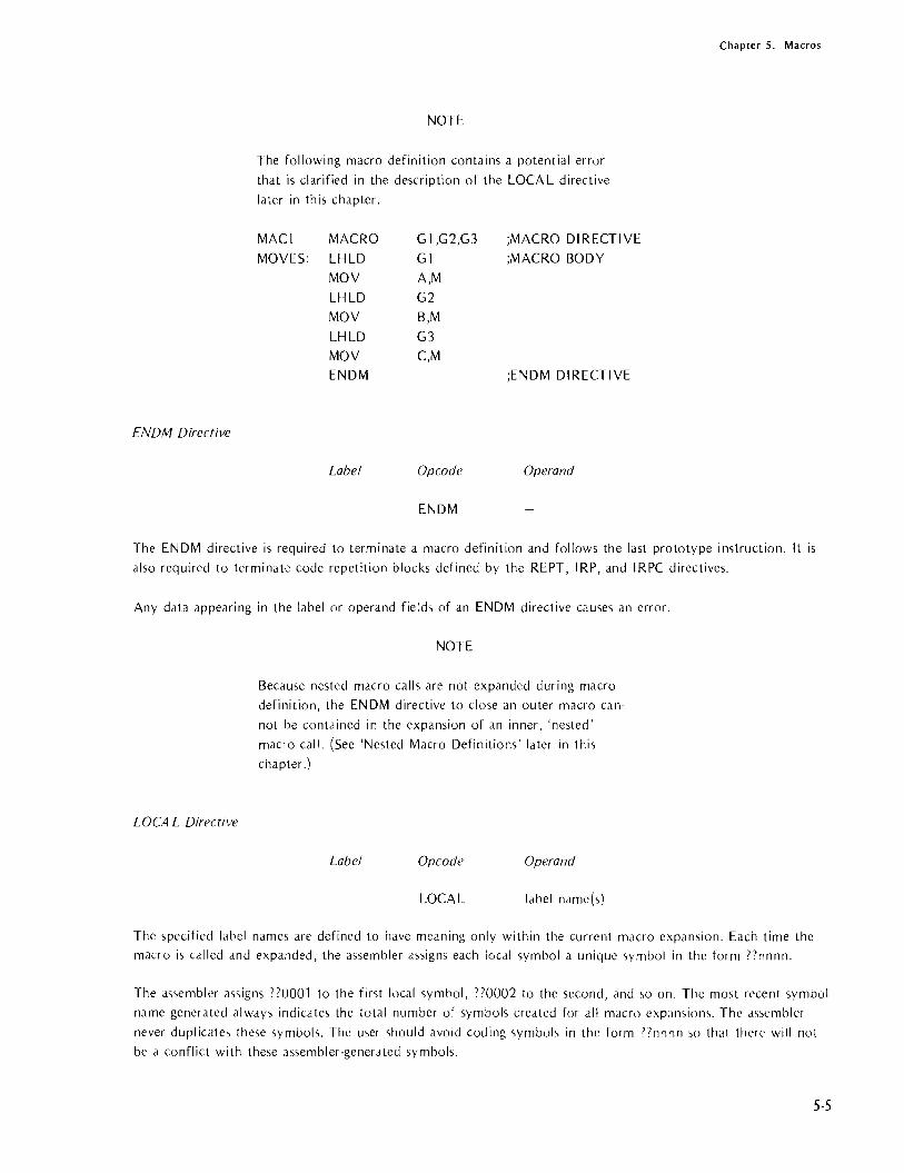
Chapter 5. Macros
ENDM Directive
NOTE
The following macro definition contains a potential error
that is clarified in the description of the LOCAL directive
later in this chapter.
MACl MACRO G 1 ,G2,G3 ;MACRO DIRECTIVE
MOVES: LHLD Gl ;MACRO BODY
MOV A,M
LHLD G2
MOV B,M
LHLD G3 MOV C,M ENDM ;ENDM DIRECTIVE
Label Opcode Operand
ENDM
The ENDM directive is required to terminate a macro definition and follows the last prototype instruction. It is
also required to terminate code repetition blocks defined by the REPT, IRP, and IRPC directives.
Any data appearing in the label or operand fields of an ENDM directive causes an error.
LOCA L Directive
NOTE
Because nested macro calls are not expanded during macro
definition, the ENDM directive to close an outer macro can
not be contained in the expansion of an inner, 'nested'
macro call. (See 'Nested Macro Definitions' later in this
chapter .)
Label Opcode Operand
LOCAL label name(s)
The specified label name, are defined to have meaning only within the current macro expamion. Each time the macro is called and expanded, the assembler assigns each local symbol a unique 5ymbol in the form 77nnnn.
The assembler assigns nOOOl to the first local symbol, 770002 to the second, and \0 on. The most recent symbol name generated always indicates the total number of symbols created for all macro expansion,. The as,embler
never duplicate, these symbols. The u,er should avoid coding symbol<., in the form )7 nnn n so that there will not
be a conflict with these assembler-generated symbols.
5-5

Chapter 5. Macros
5-6
Dummy parameters included in a macro call cannot be operands of a LOCAL directive. The scope of a dummy
parameter is always local to its own macro definition.
Local symbols can be defined only within a macro definition. Any number of LOCAL directives may appear in
a macro definition, but they must all follow the macro call and must precede the first line of prototype code.
A LOCAL directive appearing outside a macro definition causes an error. Also, a name appearing in the label
field of a LOCAL directive causes an error.
Example:
The definition of MAC1 (used as an example in the description of the MACRO directive) contains a potential error because the symbol MOVES has not been declared local. This is a potential error since no error occurs if
MAC1 is called only once in the program, and the program itself does not use MOVES as a symbol. However,
if MAC1 is called more than once, or if the program uses the symbol MOVES, MOVES is a multiply·defined
symbol. This potential error is avoided by naming MOVES in the operand field of a LOCAL directive:
MAC1 MACRO Gl,G2,G3 LOCAL MOVES
MOVES: LHLD Gl MOV A,M LHLD G2
MOV B,M LHLD G3 MOV C,M ENDM
Assume that MAC1 is the only macro in the program and that it is called twice. The first time MACl is expanded,
MOVES is replaced with the symbol ??OOOl; the second time, MOVES is replaced with ??0002. Because the
assembler encounters only these special replacement symbols, the program may contain the symbol MOVES
without causing a multiple definition.
REPT Directive
Label Opcode Operand
optional: REPT expression
The REPT directive causes a sequence of source code lines to be repeated 'expression' times. All lines appearing
between the REPT directive and a subsequent ENDM directive constitute the block to be repeated.
When 'expression' contains symbolic names, the assembler must encounter the definition of the symbol prior to encou nteri ng the expression.
The insertion of repeat blocks is performed in·line when the assembler encounters the REPT directive. No explicit call is required to cause the code insertion since the definition is an implied call for expansion.

Example 1:
Rotate accumulator right six times.
ROTR6:
Example 2:
REPT RRC ENDM
6
Chapter 5. Macros
The following REPT directive generates the source code for a routine that fills a five-byte field with the character stored in the accumulator:
Example 3:
PROGRAM CODE
LHLD REPT MOY INX ENDM
CNTR1 5 M,A
H
GENERA TED CODING
LHLD CNTR1 MOY M,A INX H MOY M,A INX H MOY M,A INX H MOY M,A INX H MOY M,A INX H
The following example illustrates the use of REPT to generate a multiplication routine. The multiplication is accomplished through a series of shifts. If this technique is unfamiliar, refer to the example of multiplication in Chapter 6. The example in Chapter 6 uses a program loop for the multiplication. This example replaces the loop with seven repetitions of the four instructions enclosed by the REPT -ENDM directives.
Notice that the expansion specified by this REPT directive causes the label SKIPAD to be generated seven times. Therefore, SKIPAD must be declared local to this macro.
FSTMUL:
SKIPAD:
MYI L.XI
REPT LOCAL RLC
INC DAD DAD ENDM RLC RNC
D,O H,O
7
SKIPAD
SKIPAD D
H
DAD D RET
;FAST MULTIPLY ROUTINE ;MULTIPLY E*A - 16-BIT RESULT ;IN H&L
;;GET NEXT MULTIPLIER BIT
;;DON'T ADD IF BIT =: ° ;;ADD MULTIPLICAND INTO ANSWER
5-7

Chapter 5. Macros
5·8
This example illustrates a classic programming trade-off: speed versus memory. Although this example executes
more quickly than the example in Chapter 6, it requires more memory.
I RP Directive
Label Opcode Operand
optional: IRP dummy param, dist>
The operand field for the I RP (indefinite repeat) directive must contain one macro dummy parameter followed
by a list of actual parameters enclosed in angle brackets. I RP expands its associated macro prototype code substituting the first actual parameter for each occurrence of the dummy parameter. IRP then expands the prototype code again substituting the second actual parameter from the list. This process continues until the list is exhausted.
The list of actual parameters to be substituted for the dummy parameter must be enclosed in angle brackets
« ». Individual items in the list must be separated by commas. The number of actual parameters in the list controls the number of times the macro body is repeated; a list of n items causes n repetitions. An empty list
(one with no parameters coded) specifies a null operand list. IRP generates one copy of the macro body sub
stituting a null for each occurrence of the dummy parameter. Also, two commas with no intervening character
create a null parameter within the list. (See 'Special Operators' later in this chapter for a description of null
operand s.)
Example:
The following code sequence gathers bytes of data from different areas of memory and then stores them in
consecutive bytes beginning at the address of STORIT:
PROGRAM CODE GENERA TED CODING
LXI H,STORIT LXI H,STORIT IRP X,<FL01,3E20H,FL03> LOA FLOl LOA X MOV M,A MOV M,A INX H INX H LOA 3E20H EN OM MOV M,A
INX H LOA FL03
MOV M,A
INX H
IRPC Directive
Label Opcode Operand
optional: IRPC dummy param,text

Chapter 5. Macros
The I RPC (indefinite repeat character) directive causes a sequence of macro prototype instructions to be repeated
for each text character of the actual parameter specified. If the text string is enclosed in optional angle brackets,
any delimiters appearing in the text string are treated simply as text to be substituted into the prototype code. The assembler generates one iteration of the prototype code for each character in the text string. For each iteration, the assembler substitutes the next character from the string for each occurrence of the dummy param
eter. A list of n text characters generates n repetitions of the IRPC macro body. An empty string specifies a
null actual operand. I RPC generates one copy of the macro body substituting a null for each occurrence of the
dummy parameter.
Example:
PROGRAM CODE GENERA TED CODING
LHLD DATE-l LHLD DATE-l MVDATE: IRPC X,1977 INX H
INX H MVI M,l
MVI M,X INX H ENDM MVI M,9
INX H
MVI M,7 INX H
MVI M,7
IRPC provides the capability to treat each character of a string individually; concatenation (described later in this
chapter) provides the capability for building text strings from individual characters.
EXITM Directive
Label Opcode Operand
optional: EXITM
EXITM provides dn alternate method for terminating a macro expansion or the repetition of a REPT, IRP, or IRPC code sequence. When [XITM is encountered, the assembler ignores all macro prototype instructions located between the EXITM and ENDM directive for this macro. Notice that EXITM may be used in addition to ENDM, but not in place (If ENDM.
When used in nested macros, EXITM cause~ an exit to the previous level of macro expansion. An EXITM within a REPT, IRP, or IRPC terminates not only the current expansion, but all subsequent iterations as well.
Any data appearing in the operand field of an EXITM directive causes an error.
Example:
EXITM is typically used to suppress unwanted macro expansion. In the following example, macro expansion is terminated when the EXITM directive is assembled because the condition X EO 0 is true.
5-9

Chapter 5. Macros
MAC3 MACRO X,Y
IF X EO 0 EXITM
ENDM
Special Macro Operators
5-10
In certain special cases, the normal rules for dealing with macros do not work. Assume, for example, that you
want to specify three actual parameters, and the second parameter happens to be the comma character. To the
assembler, the list PARMl II,PARM3 appears to be a list of four parameters where the second and third param
eters are missing. The list can be passed correctly by enclosing the comma in angle brackets: PARM1,<,),PARM3. These special operators instruct the assembler to accept the enclosed character (the comma) as an actual parameter rather than a del im iter.
The assembler recognizes a number of operators that allow special operations:
&
<>
.. II
Ampersand. Used to concatenate (link) text and dummy parameters. See the further
discussion of ampersands below.
Angle brackets. Used to delimit text, such as lists, that contain other delimiters. Notice that bfanks are usually treated as delimiters. Therefore, when an actual
parameter contains blanks (passing the instruction MOV A,M, for example) the parameter must be enclosed in angle brackets. Th is is also true for any other delimiter that is· to be passed as part of an actual parameter. To pass such text to
nested macro calls, use one set of angle brackets for each level of nesting. (See 'Nested Macro Definitions,' below.)
Double semicolon. Used before a comment in a macro definition to prevent
inclusion of the comment in expansions of the macro and reduce storage
requirements. The comment still appears in the listing of the definition.
Exclamation point (escape character). Placed before a character (usually a
delimiter) to be passed as literalized text in an actual parameter. Used primarily
to pass angle brackets as part of an actual parameter. To pass a literalized
exclamation point, issue!!. Carriage returns cannot be passed as actual parameters.
The '!' is always preserved while building an actual parameter. It is not
echoed when an actual parameter is substituted for a dummy parameter,
except when the substitution is being used to build another actual parameter.

Chapter 5. Macros
NUL In certain cases it is not necessary to pass a parameter to a macro. It is
necessary, however, to indicate the omission of the parameter. The omitted
(or null) parameter can be represented by two consecutive delimiters as in
the list PARMl "PARM3. A null parameter can also be represented by two consecutive single quotes: ",PARM2,PARM3. Notice that a null is quite different from a blank: a blank is an ASCII character with the hexadecimal representation 20H; a null has no character representation. In the assembly listing a null looks the same as a blank, but that is only because no substi· tution has taken place. The programmer must decide the meaning of a null
parameter. AI though the mechan ism is somewha t d ifferen t, the defaults taken for assembler controls provide a good example of what a null parameter can mean. For example, coding MOD85 as an assembler control specifies that
the assembler is to generate object code for the 8085. The absence of this
control (which in effect is a null parameter) specifies that the assembler
is to generate only 8080 object code.
Assembler controls are explained in the 1515-1/ 8080/8085 Macro Assembler
Operator 5 Manual, 9800292.
Example'
In a macro with the dummy parameters W ,X,Y ,Z it is acceptable for either
the X or Y parameter to be null, but not both. The following IF directive
tests for the error condition:
IF NUL X&Y
EXITM
When a macro is expanded, any ampersand preceding or following a dummy parameter in a macro definition is removed and the substitution of the actual parameter occurs at that point. When it is not adjacent to a dummy
parameter, the ampersand is not removed and is passed as part of the macro expansion text.
NOTE
The ampersand must be immediately adjacent to the text being
concatenated; intervening blanks are not allowed.
If nested macro definitions (described below) contain ampersands, the only ampersands removed are those adjacent to dummy parameters belonging to the macro definition currently being expanded. All ampersands must be re
moved by the time the expansion of the encompassing macro body is performed. Exceptions force illegal character
errors.
Ampersands placed inside strings are recognized as concatenation delimiters when adjacent to dummy parameters; similarly, dummy parameters within character strings are recognized only when they are adjacent to ampersands.
Ampersands are not recognized as operators in comments.
5·11

("hdp rer 5. Macros
Nested Macro Definitions
A macro definition can be contained completely within the,body of another macro definition (that is, macro
definitions can be nested). The body of a macro consists of all text (including nested macro definitions)
hounded by matching MACRO and ENDM directives. The assembler allows any number of macro definitions to
be nested.
When a higher-level macro is called for expansion, the next lower-level macro is defined and eligible to be called
for expansion. A lower-level macro cannot be called unless all higher-level macro definitions have already been called and expanded.
A new macro may be defined or an existing macro redefined by a nested macro definition depending on whether the name of the nested macro i, a new label or has previously been established as a dummy parameter in a !llghcr-level macro definition. Therefore, each time a higher-level macro is called, a lower-level definition can be ddined difterently if the two contain common dummy parameter'>. Such redefinition can be costly, however, in tel inS 01 assembler execution ,>peed.
Since IRP, IRPC, and REPT blocks con'>titute macro definitions, they also can be nested within another definition Cleated by IRP, IRPC, REPT, or MACRO directive'>. In addition, an element in an IRP or IRPC actual parameter
li.,t (enclosed in angle brackets) may itself be a list of bracketed parameters; that is, lists of parameters can contain elements that arc also lists.
Example:
LISTS MACRO PARAM1,PARAM2
EN OM
MACRO CALLS
Once a macro has been defined, it can be called any number of times in the program. The call consists of the
macro name and any actual parameters that are to replace dummy parameters during macro expansion. During assembly, each macro call is replaced by the macro definition code; dummy parameters are replaced by actual parameters.
Macro Call Format
Label
optional:
5·12
Opcode
macro name
Operand
optional actual
parameter(s)

Chapter 5. Macros
The assembler must encounter the macro definition before the first call for that macro. Otherwise, the macro
call is assumed to be an illegal opcode. The assembler inserts the macro body identified by the macro name each time it encounters a call to a previously defined macro in your program.
The positioning of actual parameters in a macro call is critical since the substitution of parameters is based
solely on position. The first-listed actual parameter replaces each occurrence of the first-listed dummy parameter; the second actual parameter replaces the second dummy parameter, and so on. When coding a macro call,
you must be certain to list actual parameters in the appropriate sequence for the macro.
Notice that blanks are usually treated as delimiters. Therefore, when an actual parameter contains blanks (passing the instruction MOY A,M, for example) the parameter must be enclosed in angle brackets. This is also
true for any other delimiter that is to be passed as part of an actual parameter. Carriage returns cannot be passed as actual parameters.
If a macro call specifies more actual parameters than are listed in the macro definition, the extra parameters are ignored. If fewer parameters appear in the call than in the definition, a null replaces each missing parameter.
Example:
The following example shows two calls for the macro LOAD. LOAD is defined as follows:
LOAD MACRO Gl,G2,G3 LOCAL MOYES
MOYES: LHLD Gl MOY A,M LHLD G2 MOY B,M LHLD G3 MOY C,M ENDM
LOAD simply loads the accumulator with a byte of data from the location specified by the first actual parameter, the B register with a byte from the second parameter, and the C register with a byte from the third parameter.
The first time LOAD is called, it is used as part of a routine that inverts the order of three bytes in memory.
The second time LOAD is called, it is part of a routine that adds the contents of the B register to the accumulator and then compares the result with the contents of the C register.
5-13
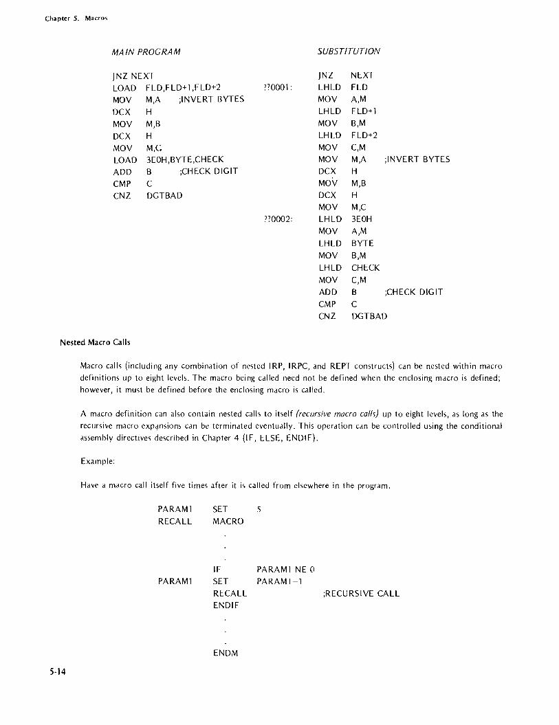
Chapter 5. Macros
MAIN PROGRAM SUBSTITUTION
JNZ NEXT JNZ NEXT
LOAD FLD,FLD+1,FLD+2 ??OOOl : LHLD FLD MOY M,A ;INYERT BYTES MOY A,M
DCX H LHLD FLD+1
MOY M,B MOY B,M
DCX H LHLD FLD+2
MOY M,G MOY C,M
LOAD 3EOH ,BYTE ,CHECK MOY M,A ;INYERT BYTES
ADD B ;CHECK DIGIT DCX H
CMP C MOY M,B
CNZ DGTBAD DCX H MOY M,C
??0002: LHLD 3EOH
MOY A,M
LHLD BYTE
MOY B,M LHLD CHECK
MOY C,M ADD B ;CHECK DIGIT
CMP C CNZ DGTBAD
Nested Macro Calls
5·14
Macro calls (including any combination of nested IRP, IRPC, and REPT constructs) can be nested within macro definitions up to eight levels. The macro being called need not be defined when the enclosing macro is defined; however, it must be defined before the enclosing macro is called.
A macro definition can also contain nested calls to itself (recursive macro calls) up to eight levels, as long as the recursive macro expansions can be terminated eventually. This operation can be controlled using the conditional assembly directives described in Chapter 4 (IF, ELSE, ENDIF).
Example:
Have a macro call itself five times after it is called from elsewhere in the program.
PARAM1
RECALL
PARAM1
SET MACRO
5
IF PARAM1 NE 0 SET PARAM 1-1 RECALL ENDIF
ENDM
;RECURSIYE CALL

Chapter 5. Macros
Macro Expansion
When a macro is called, the actual parameters to be substituted into the prototype code can be passed in one of
two modes. Normally, the substitution of actual parameters for dummy parameters is simply a text substitution.
The parameters are not evaluated until the macro is expanded.
If a percent sign (%) precedes the actual parameter in the macro call, however, the parameter is evaluated
immediately, before expansion occurs, and is passed as a decimal number representing the value of the paramo
eter. In the case of I RPC, a '%' preceding the actual parameter causes the entire text string to be treated as a
single parameter. One IRPC iteration occurs for each digit in the decimal string passed as the result of immediate
evaluation of the text string.
The normal mechanism for passing actual parameters is adequate for most applications. Using the percent sign
to pre-evaluate parameters is necessary only when the value of the parameter is different within the local con·
text of the macro definition as compared to its global value outside the macro definition.
Example:
The macro shown in this example generates a number of rotate instructions. The parameters passed in the macro
call determine the number of positions the accumulator is to be rotated and whether rotate right or rotate left
instructions are to be generated. Some typical calls for this macro are as follows:
SHIFTR
SHIFTR
'R',3
L,%COUNT -1
The second call shows an expression used as a parameter. This expression is to be evaluated immediately rather than passed simply as text.
The definition of the SH 1FT R macro is shown below. This macro uses the conditional I F directive to test the validity of the first parameter. Also, the REPT macro directive is nested within the SHIFTR macro.
SHIFTR MACRO X,Y IF X EO 'R'
REPT Y
RAR
ENDM
ENDIF IF X NE 'L'
EXITM
ELSE
REPT Y
RAL ENDM
ENDIF
ENDM
The indentation shown in the definition of the SHIFTR macro graphically illustrates the relationships of the IF,
ELSE, ENDIF directives and the REPT, ENDM directives. Such indentation is not required in your program, but may be desirable as documentation.
5-15

Chapter S. Macros
The SHIFTR macro generates nothing if the first parameter is neither R nor L. Therefore, the following calls
produce no code. The result in the object program is as though the SHIFTR macro does not appear in the
source program.
SHIFTR 5 SHIFTR 'B',2
The following call to the SHIFTR macro generates three RAR instructions:
SHIFTR 'R',3
Assume that a SET directive elsewhere in the source program has given COUNT the value 6. The following call generates five RAL instructions:
SHIFTR 'L ',%COUNT -1
The following is a redefinition of the SHIFTR macro. In this definition, notice that concatenation is used to
form the RAR or RAL operation code. If a call to the SHIFTR macro specifies a character other than R or L, illegal operation codes are generated. The assembler flags all illegal operation codes as errors.
SHIFTR MACRO
REPT
RA&X
ENOM
ENOM
X,Y Y
NULL. MACROS
A macro may legally comprise only the MACRO and ENOM directives. Thus, the following is a legal macro definition:
NAOA MACRO ENOM
Pl,P2,P3,P4
A call to this macro produces no source code and therefore has no effect on the program.
Although there is no reason to write such a macro, the null (or empty) macro body has a practical application. F or example, all the macro prototype instructions might be enclosed with I F -END I F condi tional directives. When none of the specified conditions is satisfied, all that remains of the macro is the MACRO directive and the ENOM directive.
SAMPLE MACROS
The following sample macros further demonstrate the use of macro directives and operators.
5·16

Chapter 5. Macros
Example 1: Nested I RPC
The following macro definition contains a nested IRPC directive. Notice that the third operand of the outer macro becomes the character string for the I RPC:
MOVE MACRO IRPC LHLD SHLD
ENDM ENDM
X,Y,Z PARAM,Z X&&PARAM Y&&PARAM
Assume that the program contains the call MOVE SRC,DST,123. The third parameter of this call is passed to
the I RPC. This has the same effect as coding I RPC PARAM,123. When expanded, the MOVE macro generates the following source code:
LHLD SRC1 SHLD DST1 LHLD SRC2
SHLD DST2 LHLD SRC3 SHLD DSn
Notice the use of concatenation to form labels in this example.
Example 2: Nested Macros U,ed to Generate DB Directives
This example generates a number of DB 0 directives, each with its own label. Two macros are used for this purpose: INC and BLOCK. The INC macro is defined as follows:
INC $ SAVE GEN
F1 &F2: $ RESTORE
MACRO
DB
ENDM
F1,F2
o ;GENERATE LABELS & DB's
The BLOCK macro, which accepts the number of DB's to be generated (NUMB) and a label prefix (PREFIX), is
defined as follows:
$
BLOCK MACRO SAVE NOGEN COUNT
COUNT
SET
REPT
SET INC ENDM
$ RESTORE ENDM
NUMB,PREFIX
o NUMB COUNT+1 PREFIX,%COUNT ;NESTED MACRO CALL
S-17

Chapter 5. Macros
5-18
The macro call BLOCK 3,LAB generates the following source code:
LAB1: LAB2: LAB3:
BLOCK DB DB DB
3,LAB o o o
The assembler controls specified in these two macros (the lines beginning with $) are used to clean up the assembly listing for easier reading. The source code shown for the call BLOCK 3,LAB is what appears in the assembly listing when the controls are used. Without the controls, the assembly listing appears as follows:
BLOCK 3,LAB COUNT SET 0
REPT 3 COUNT SET COUNT+1
INC LAB,%COUNT ENDM
COUNT SET COUNT+1 INC LAB,%COUNT
LAB1 : DB 0 COUNT SET COUNT+l
INC LAB,%COUNT LA,B2: DB 0 COUNT SET COUNT+l
INC LAB,%COUNT LAB3: DB 0
Example 3: A Macro that Converts Itself into a Subroutine
In some cases, the in-line coding substituted for each macro call imposes an unacceptable memory requirement. The next three examples show three different methods for converting a macro call into a subroutine call. The first time the SBMAC macro is called, it generates a full in-line substitution which defines the SUBR subroutine. Each subsequent call to the SBMAC macro generates only a CALL instruction to the SUBR subroutine.
Within the following examples, notice that the label SUBR must be global so that it can be called from outside the first expansion. This is possible only when that part of the macro definition contai ning the global label is called only once in the entire program.
Method #1: Nested Macro Definitions
Macros can be redefined during the course of a program. In the following example, the definition of SBMAC contains its own redefinition as a nested macro. The first time SBMAC is called, it is full expanded, and the redefinition of SBMAC replaces the original definition. The second time SBMAC is called, only its redefinition (a CALL instruction) is expanded.

Chapter S. Macros
SBMAC MACRO SBMAC MACRO
CALL SUBR ;;REDEFINITION OF SBMAC ENDM CALL SUBR
LINK: IMP DUN SUBR:
RET DUN:
ENDM
Notice that both versions of SBMAC contain CALL SUBR instructions. This is necessary to provide a return address at the end of the SUBR routine. The jump instruction labelled LINK is required to prevent the SUBR subroutine from executing a return to itself. Notice that the return address for the second CALL SUBR instruction would be SUBR if the jump instruction were omitted. The IMP DUN instruction simply transfers control past the end of the subroutine.
NOTE
The assembler allows the use of a source line consisting only of a label. Such a label is assigned to the next source line for which code or data is generated. Notice that
neither code nor data is generated for an ENDM directive, so the label DUN is assigned to whatever instruction follows the ENDM directive. This construct is required because the ENDM directive itself may not be given a label.
Method #2: Conditional Assembly
The second method for altering the expansion of the SBMAC macro uses conditional assembly. I n this example, a switch (FIRST) is set TRUE just before the first call for SBMAC. SBMAC is defined as follows:
TRUE FALSE FIRST
SBMAC
FIRST LINK:
SUBR:
DUN:
EQU EQU
SET MACRO CALL SUBR IF SET
JMP
RET
ENDIF ENDM
OFFH 0 TRUE
FIRST FALSE DUN
5·19

Chapter 5. Macros
5-20
The first call to SBMAC expands the full definition, including the call to and definition of SUBR:
SBMAC CALL SUBR
LINK: SUBR:
DUN:
IF JMP
RET
ENDIF
FIRST DUN
Because FI RST is TRUE when encountered during the first expansion of SBMAC, all the statements between IF and ENDIF are assembled into the program. In subsequent calls, the conditionally-assembled code is skipped so that the subroutine is not regenerated. Only the following expansion is produced:
SBMAC CALL IF
Method #3: Conditional Ass,embly with EXITM
SUBR FIRST
The third method for altering the expansion of SBMAC also uses conditional assembly, but uses the EXIT M directive to suppress unwanted macro expansion after the first call. EXITM is effective when FI RST is FALSE, which it is after the first call to SBMAC.
TRUE FALSE FIRST SBMAC
FIRST
SUBR:
DUN:
EQU EQU SET MACRO CALL IF EXITM ENDIF SET JMP
RET
ENDM
OFFH o TRUE
SUBR NOT FIRST
FALSE DUN

Chapter S. Macros
Example 4: Computed GOTO Macro
This sample macro presents an implementation of a computed GOTO for the 8080 or 8085. The computed GOTO, a common feature of many high level languages, allows the program to jump to one of a number of different locations depending on the value of a variable. For example, if the variable has the value zero, the program jumps to the first item in the list; if the variable has the value 3, the program jumps to the fourth address in the list.
In this example, the variable is placed in the accumulator. The list of addresses is defined as a series of DW directives starting at the symbolic address TABLE. This macro (T I UMP) also modifies itself with a nested definition. Therefore, only the first call to the T I UMP macro generates the calculated GOTO routine. Subsequent calls produce only the jump instruction IMP T ICODE.
TIUMP TICODE:
TIUMP
MACRO ADD MVI MOV DAD MOV INX MOV XCHG PCHL MACRO IMP ENDM ENDM
;IUMP TO A-TH ADDR IN TABLE A ;MULTIPLY A BY 2 D,O ;CLEAR DREG E,A ;GET TABLE OFFSET INTO D&E D ;ADD OFFSET TO TABLE ADDR IN H&L E,M ;GET 1 ST ADDRESS BYTE H D,M ;GET 2ND ADDRESS BYTE
;1 UMP TO ADDRESS ;REDEFINE TIUMP TO SAVE CODE
TICODE ;NEXT CALL JUMPS TO ABOVE CODE
Notice that the definition of the T I UMP~: does not account for loading the address of the address t <,Ie into the Hand L registers; the user must load this address just before calling the T JUMP macro. The following shows the coding for the address table (TABLE) and a typical call sequence for the T I UMP macro:
TABLE:
MVI LXI TIUMP
DW
A,2 H,TABLE
LOCO DW LOCl DW LOC2
The call sequence shown above causes a jump to LOC2.
5-21

Chapter 5. Macros
5-22
Example 5: Using IRP to Define the Jump Table
The T JUMP macro becomes even more useful when a second macro (GOTO) is used to define the jump table,
load the address of the table into the Hand L registers, and then call TJ UMP. The GOTO macro is defined as follows:
GOTO
JTABLE:
MACRO LOCAL
LOA
LXI
TJUMP IRP
OW ENDM ENDM
INDEX,LlST
JT ABLE INDEX
H,jTABLE
FORMAL,<LlST>
;LOAD ACCUM WITH INDEX ;LOAD H&L WITH TABLE ADDRESS ;CALL TJUMP MACRO
FORMAL ;SET UP TABLE
A typical call to the GOTO macro would be as follows:
GOTO CASE,<COUNT,TIMER,DATE,PTDRVR>
This call to the GOTO macro builds a table of OW directives for the labels COUNT, TIMER, DATE, and PTDR VR. It then loads the base address of the table into the Hand L registers and calls the T JUMP macro. If the value of the variable CASE is 2 when the GOTO macro is called, the GOTO and T JUMP macros together cause a jump to the address of the DATE routine.
Notice that any number of addresses may be specified in the list for the GOTO routine as long as they all fit on a single source line. Also, the GOTO macro may be called any number of times, but only one copy of the
coding for the TJUMP is generated since the TJUMP macro redefines itself to generate only a JMP TJCODE instruction.

6. PROGRAMMING TECHNIQUES
This chapter describes some techniques that may be of help to the programmer.
BRANCH TABLES PSEUDO-SUBROUTINE
S:.Jppose a program consists of several separate routines, any of which may be executed depending upon some
initial condition (such as a number passed in a register). One way to code this would be to check each condition
sequentially and branch to the routines accordingly as follows:
CONDITION = CON DillON 1? IF YES BRANCH TO ROUTINE 1 CONDITION::: CONDITION 2? IF YES BRANCH TO ROUTINE 2
BRANCH TO ROUTINE N
A sequence as above is inefficient, and can be improved by using a branch table.
The logic at the beginning of the branch table program loads the starting address of the branch table into the H and L registers. The branch table itself consists of a list of starting addresses for the routines to be branched to. Using the Hand L registers as a pointer, the branch table program loads the selected routine's starting address into the program counter, thus effecting a jump to the desired routine. For example, consider a program that executes one of eight routines depending on which bit of the accumulator is set:
Jump to routine 1 if the accumulator holds 00000001 2" " " 0000001 0
3 " " " 00000100 4 " " " 00001000 5 " " " 00010000
6 " " " 00100000 7 " " " 01000000
8 " " " 10000000
A program that provides such logic follows. The program is termed a 'pseudo-subroutine' because it is treated as a subroutine by the programmer (i.e., it appears just once in memory), but is entered via a regular JUMP instruction rather than via a CALL instruction.
6-1

Chapter 6. Programming Techniques
6-2
Main Program
~ - - -
normal subroutine return
sequence not followed by branch table program
Branch Table
Program Jump
Routines

Chapter 6. Programming Techniques
Label Code Operand
START: LXI H,BTBL ;REGISTERS HAND L WILL ;POINT TO BRANCH TABLE
GTBIT: RAR
IC GETAD INX H ;(H,L)=(H,L)+2 TO INX H ;POINT TO NEXT ADDRESS
;IN BRANCH TABLE
JMP GTBIT GETAD: MOV E,M ;BIT FOUND
INX H ;LOAD I UMP ADDRESS ;INTO 0 AND E REGISTERS
MOV D,M XCHG ;EXCHANGE 0 AND E
;WITH HAND L PCHL ;1 UMP TO ROUTINE
;ADDRESS
BTBL: OW ROUTl ;BRANCH TABLE. EACH OW ROUT2 ;ENTRY IS A TWO-BYTE OW ROUn ;ADDRESS OW ROUT4 ;HELD LEAST SIGNIFICANT OW ROUTS ;BYTE FIRST OW ROUT6 OW ROUn OW ROUT8
The control routine at START uses the Hand L registers as a pointer into the branch table (BTBL) corresponding to the bit of the accumulator that is set. The routine at GET AO then transfers the address held in the corresponding branch table entry to the Hand L registers via the 0 and E registers, and then uses a PCHL instruction, thus transferring control to the selected routine.
TRANSFERRING DATA TO SUBROUTINES
A subroutine typically requires data to perform its operations. In the simplest case, this data may be transferred
in one or more registers.
Sometimes it is more convenient and economical to let the subroutine load its own registers. One way to do this is to place a list of the required data (called a parameter list) in some data area of memory, and pass the address of this list to the subroutine in the Hand L registers.
6-3

Chapter 6. Programming Techniques
6-4
For example, the subroutine ADSUB expects the address of a three-byte parameter list in the Hand L registers.
It adds the first and second bytes of the list, and stores the result in the third byte of the list:
Label Code
LXI
CALL
RET1 :
PLlST: DB DB
DS
LXI
CALL
RET2:
L1ST2: DB
DB DS
ADSUB: MOY
INX
MOY
ADD
INX
MOY
RET
Operand
H,PLlST
ADSUB
6 8
H,L1ST2
ADSUB
10
3S
A,M H
B,M
B
H
M,A
Comment
;LOAD HAND L WITH
;ADDRESSES OF THE PARAM
;ETER LIST
;CALL THE SUBROUTINE
;FIRST NUMBER TO BE ADDED
;SECOND NUMBER TO BE
;ADDED
;RESULT WILL BE STORED HERE
;LOAD HAND L REGISTERS
;FOR ANOTHER CALL TO ADSUB
;GET FIRST PARAMETER
;INCREMENT MEMORY
;ADDRESS
;GET SECOND PARAMETER
;ADD FIRST TO SECOND
;INCREMENT MEMORY
;ADDRESS
;STORE RESULT AT THIRD
;PARAMETER STORE
;RETURN UNCONDITIONALLY
The first time ADSUB is called, it loads the A and B registers from PLiST and PLlST+l respectively, adds them,
and stores the result in PLiST +2. Return is then made to the instruction at RETl.

Chapter 6. Programming Techniques
First call to ADSUB:
H L
ADSUB: D o
06 PLiST
08 PLiST +1
OEH PLiST +2
The second time ADSUB is called, the Hand L registers point to the parameter list LlST2. The A and B registers are loaded with 10 and 35 respectively, and the sum is stored at LlST2+2. Return is then made to the instruction at RET2.
Note that the parameter lists PLiST and LlST2 could appear anywhere in memory without altering the results
produced by ADSUB.
This approach does have its limitations, however. As coded, ADSUB must receive a list of two and only two numbers to be added, and they must be contiguous in memory. Suppose we wanted a subroutine (GENAD)
which would add an arbitrary number of bytes, located anywhere in memory, and leave the sum in the accumulator.
This can be done by passing the subroutine a parameter list which is a list of addresses of parameters, rather
than the parameters themselves, and signifying the end of the parameter list be a number whose first byte is
FFH (assuming that no parameters will be stored above address FFOOH).
Call to GENAD:
H L
GENAD: D D ~
l PARMI
ADRI PARM4 ADR2 ADR3 PARM3 ADR4 FFFF PARM2
As implemented below, GE NAD saves the current sum (beginning with zero) in the C register. It then loads the address of the first parameter into the D and E registers. If this address is greater than or equal to FFOOH, it
reloads the accumulator with the sum held in the C register and returns to the calling routine. Otherwise, it
6-5

Chapter 6. Programming Techniques
loads the parameter into the accumulator and adds the sum in the C register to the accumulator. The routine
then loops back to pick up the remaining parameters.
Label
PLlST:
PARM1 :
PARM4:
PARM3:
PARM2:
GENAD: LOOP:
BACK:
Code
LXI CALL
HALT
OW
Operand
H,PLlST GENAD
PARM1
OW PARM2 OW PARM3 OW PARM4
OW
DB DB
DB
DB
XRA MOV
MOV
INX
MOV
CPI
JZ MOV
LDAX
ADD
INX
JMP MOV
RET END
OFFFFH
6 16
13
82
A
C,A E,M
H
A,M
OFFH
BACK D,A 0
C
H
LOOP
A,C
Comment
;LOAD ADDRESS OF ;PARAMETER ADDRESS LIST
;LlST OF PARAMETER ADDRESSES
;TERMINATOR
;CLEAR ACCUMULATOR ;SAVE CURRENT TOTAL IN C ;GET LOW ORDER ADDRESS BYTE
;OF FIRST PARAMETER
;GET HIGH ORDER ADDRESS BYTE
;OF FIRST PARAMETER
;COMPARE TO FFH
;IF EQUAL, ROUTINE IS COMPLETE ;0 AND E NOW ADDRESS PARAMETER
;LOAD ACCUMULATOR WITH PARAMETER ;ADD PREVIOUS TOTAL ;INCREMENT HAND L TO POINT ;TO NEXT PARAMETER ADDRESS
;GET NEXT PARAMETER ;ROUTINE DONE - RESTORE TOTAL
;RETURN TO CALLING ROUTINE

Chapter 6. Programming Techniques
Note that GENAO could add any combination of the parameters with no change to the parameters themselves.
The sequence:
PLlST:
LXI CALL
OW OW OW
H,PLlST GENAO
PARM4 PARM1 OFFFFH
would cause PARM1 and PARM4 to be added, no matter where in memory they might be located (excluding addresses above FFOOH).
Many variations of parameter passing are possible. For example, if it is necessary to allow parameters to be stored at any address, a calling program can pass the total number of parameters as the first parameter; the subroutine then loads this first parameter into a register and uses it as a counter to determine when all parameters had been accepted.
SOFTWARE MULTIPLY AND DIVIDE
The multiplication of two unsigned 8-bit data bytes may be accomplished by one of two techniques: repetitive addition, or use of a register shifting operation.
Repetitive addition provides the simplest, but slowest, form of multiplication. For example, 2AH*74H may be generated by adding 74H to the (initially zeroed) accumulator 2AH times.
Shift operations provide faster multiplication. Shifting a byte left one bit is equivalent to multiplying by 2, and shifting a byte right one bit is equivalent to dividing by 2,. The following process will produce the correct 2-byte result of multiplying a one byte multiplicand by a one byte multiplier:
A. Test the least significant bit of multiplier. If zero, go to step b. If one, add the multiplicand to the most significant byte of the result.
B. Shift the entire two-byte result right one bit position.
C. Repeat steps a and b until all 8 bits of the multiplier have been tested.
For example, consider the multiplication: 2AH*3CH=908H
Step 1:
Step 2:
Step 3:
Test multiplier O-bit; it is 0, so shift 16-bit result right one bit.
Test multiplier l-bit; it is 0, so shift 16-bit result right one bit.
Test multiplier 2-bit; it is 1, so add 2AH to high-order byte of result and shift 16-bit result right one bit.
6·7

Chapter 6. Programming Techniques
6·8
Step 4: Test multiplier 3-bit; it is 1, so add 2AH to high-order byte of result and shift 16-bit
result right one bit.
Step 5: Test multiplier 4-bit; it is 1, so add 2AH to high-order byte of result and shift 16-bit
result right one bit.
Step 6: Test multiplier S-bit; it is 1, so add 2AH to high-order oyte of result and shift 16-bit
result right one bit.
Step 7: Test multiplier 6-bit; it is 0, so shift 16-bit result right one bit.
Step 8: Test multiplier 7-bit; it is 0, so shift 16-bit result right one bit.
The result produced is 0908.
MULTIPLIER MULTIPLICAND
Start 00111100(3C) 00101 01 0(2A)
Step 1 a .............................. .
b
Step 2 a .............................. .
b
Step 3 a .............................. .
b
Step 4 a .............................. .
b
Step 5 a .............................. .
b
Step 6 a .............................. .
b
Step 7 a .............................. . b
Step 8 a .............................. .
b
HIGH-ORDER BYTE
OF RESULT
100000000
00000000
100000000
00101010
100010101
00111111
00011111
101001001
00100100
101001110
00100111
00010011
00001001
LOW-ORDER BYTE
OF RESULT
00000000
00000000
00000000
00000000
00000000
00000000
10000000
10000000
11000000
11000000
01100000
10110000
11011000(908)
Since the multiplication routine described above uses a number of important programming techniques, a sample
program is given with comments.
The program uses the B register to hold the most significant byte of the result, and the C register to hold the
least significant byte of the result. The 16-bit right shift of the result is performed in the accumulator by two
rotate-right-through-carry i nstruc tions.

Chapter 6. Programming Techniques
Zero carry and then rotate B:
B C
D Then rotate C to complete the shift:
B C
D Register D holds the multiplicand, and register C originally holds the multiplier.
MULT: MVI B,O ;INITIALIZE MOST SIGNIFICANT BYTE
;OF RESULT
MVI E,9 ;BIT COUNTE R
MULTO: MOV A,C ;ROTATE LEAST SIGNIFICANT BIT OF
RAR ;MULTIPLIER TO CARRY AND SHIFT
MOV C,A ;LOW-ORDER BYTE OF RESULT
DCR E
jZ DONE ;EXIT IF COMPLETE
MOV A,B
jNC MULTl
ADD D ;ADD MULTIPLICAND TO HIGH-
;ORDER BYTE OF RESULT IF BIT
;WAS A ONE
MULT1: RAR ;CARRY=O HERE SHIFT HIGH-
;ORDER BYTE OF RESULT
MOV B,A
jMP MULTO
DONE:
An analogous procedure is used to divide an unsigned 16-bit number by an unsigned 16-bit number. Here, the
process involves subtraction rather than addition, and rotate-left instructions instead of rotate-right instructions.
6-9

Chapter 6. Programming Techniques
6-10
The following reentrant program uses the Band C registers to hold the dividend and quotient, and the D and E
register to hold the divisor and remainder. The Hand L registers are used to store data temporarily.
DIV: MOV
CMA
MOV
MOV
CMA
MOV
INX
LXI
MVI
DVO: PUSH
DAD
INC
XTHL
DVl: POP
PUSH
MOV
RAL
MOV
MOV
RAL
MOV
MOV
RAL
MOV
MOV
RAL
MOV
POP
DCR
JNZ
;POST-DIVIDE CLEAN UP
A,D
D,A
A,E
E,A
D
H,O
A,I7
H
D
DVI
H
PSW
A,C
C,A
A,B
B,A
A,L
L,A
A,H
H,A
PSW
A
DVO
;NEGATE THE DIVISOR
;FOR TWO'S COMPLEMENT
;INITIAL VALUE FOR REMAINDER
;INITIALIZE LOOP COUNTER
;SAVE REMAINDER
;SUBTRACT DIVISOR (ADD NEGATIVE)
;UNDER FLOW, RESTORE HL
;SAVE LOOP COUNTER (A)
;4 REGISTER LEFT SHIFT
;WITH CARRY
;CY->C>B >L->H
;RESTORE LOOP COUNTER (A)
;DECREMENT IT
;KEEP LOOPING
;SHIFT REMAINDER RIGHT AND RETURN IN DE
ORA A
MOV A,H
RAR
MOV D,A
MOV A,L
RAR
MOV E,A
RET
END

Chapter 6. Programming Techniques
MUL TIBYTE ADDITION AND SUBTRACTION
The carry flag and the ADC (add with carry) instructions may be used to add unsigned data quantities of arbitrary length. Consider the following addition of two three-byte unsigned hexadecimal numbers:
32AF8A +84BA90
B76A1A
To perform this addition, add to the low-order byte using an ADD instruction. ADD sets the carry flag for use
in subsequent instructions, but does not include the carry flag in the addition. Then use ADC to add to all higher order bytes.
32
84
B7
carry = 1
AF
BA
""'Y = IS
8A
90
lA
The following routine will perform this multibyte addition, making these assumptions:
The E register holds the length of each number to be added (in this case, 3).
The numbers to be added are stored from low-order byte to high-order byte beginning at memory locations
FI RST and SECND, respectively.
The result will be stored from low-order byte to high-order byte beginning at memory location FIRST, replacing the original contents of these locations.
MEMORY LOCATION before after
FIRST 8A -..+ ~ lA } carry
FIRST+1 AF + ~ 6A ~ carry
FIRSTt2 32 +-. B7
SECND 90 90
SECND+l BA BA
SECND+2 84 84
6-11

Chapter 6. Programming Techniques
The following routine uses an ADC instruction to add the low-order bytes of the operands. This could cause
the result to be high by one if the carry flag were left set by some previous instruction. This routine avoids
the problem by clearing the carry flag with the XRA instruction just before LOOP.
Label
MADD:
LOOP:
DONE:
FIRST:
SECND:
Code
LXI
LXI
XRA
LDAX
ADC
STAX
DCR ]Z INX
INX
]MP
DB DB
DB
DB
DB
DB
Operand
B,FIRST
H,SECND
A B
M
B
E
DONE B
H
LOOP
90H
OBAH
84H
8AH
OAFH
32H
Comment
;B AND C ADDRESS FI RST
;H AND L ADDRESS SECND
;CLEAR CARRY FLAG
;LOAD BYTE OF FIRST
;ADD BYTE OF SECND ;WITH CARRY ;STORE RESULT AT FIRST ;DONE IF E = 0
;POINT TO NEXT BYTE OF
;FIRST
;POINT TO NEXT BYTE OF ;SECND
;ADD NEXT TWO BYTES
Since none of the instructions in the program loop affect the carry flag except ADC, the addition with carry will
proceed correctly.
When location DONE is reached, bytes FIRST through FIRST+2 will contain lA6AB7, which is the sum shown
at the beginning of this section arranged from low-order to high-order byte.
In order to create a multibyte subtraction routine, it is necessary only to duplicate the multibyte addition routine of this section, changing the ADC instruction to an SBB instruction. The program will then ,ubtract the number beginning at SECND from the number beginning at FIRST, placing the re,ult at FIRST.
DECIMAL ADDITION
6-12
Any 4-bit data quantity may be treated as a decimal number a, long as it represents one of the decimal digits from 0 through 9, and does not contain any of the bit patterns representing the hexadecimal digits A through F. In order to preserve this decimal interpretation when performing addition, the value 6 must be added to the 4-bit quantity whenever the addition produces a result between 10 and 15. This is because each 4-bit data quantity can hold 6 more combinations of bits than there are decimal digits.

Chapter 6. Programming Techniques
Decimal addition is performed by letting each 8-bit byte represent two 4-bit decimal digits. The bytes are
summed in the accumulator in standard fashion, and the DAA (decimal adjust accumulator) instruction is then used to convert the 8-bit binary result to the correct representation of 2 decimal digits. For multibyte strings,
you must perform the decimal adjust before adding the next higher·order bytes. This is because you need the
carry flag setting from the DAA instruction for adding the higher·order bytes.
To perform the decimal addition:
the process works as follows:
2985
+4936
7921
1. Clear the Carry and add the two lowest-order digits of each number (remember that each 2
decimal digits are represented by .one byte).
carry
85 = 10000101 B 36 = 00110110B
o
~Q]10111011B
Carry = 0 , Auxiliary Carry = 0
The accumulator now contains OBBH.
2. Perform a DAA operation. Since the rightmost four bits are greater than 9, a 6 is added to the accumulator.
Accumulator = 10111011 B
6 = 0110B
11000001 B
Since the leftmost bits are greater than 9, a 6 is added to these bits, thus ~etting the carry flag.
Accumulator = 11000001 B
6 = 0110 B
Carry flag == 1
/]00100001B
The accumulator now contains 21 H. Store these two digits.
6-13

Chapter 6. Programming Techniques
3. Add the next group of two digits:
carry
29 = 00101001 B
49 = 01001001 B
g]01110011B
Carry = 0 ~ 'AUXiliary Carry = 1
The accumulator now contains 73H.
4. Perform a DAA operation. Since the auxiliary carry flag is set, 6 is added to the accumulator.
Accumulator = 01110011B
6= 0110B
Carry flag = 0
/m01111001B
Since the leftmost 4 bits are less than 10 and the carry flag is reset, no further action occurs.
Thus, the correct decimal result 7921 is generdted in two bytes.
A routine which adds decimal numbers, then, is exactly analogous to the multibyte addition routine MADD of
the last section, and may be produced by inserting the instruction DAA after the ADC M instruction of that
example.
Each iteration of the program loop will add two decimal digits {one byte) of the numbers.
DECIMAL SUBTRACTION
6-14
()(~cimal subtraction is considerably more complicated than decimal addition. In general, the process consists of
generating the tens complement of the subtrahend digit, and then adding the result to the minuend digit. For example, to subtract 34 from 56, form the tens complement of 34 (99-34=65+ 1 =66). Then, 56+66= 122. By truncating off the carry out of the high order digit, we get 22, the correct result.
The problem of handling borrows arises in multibyte decimal subtractions. When no borrow occurs from a sub
tract, you want to use the tens complement of the subtrahend for the next operation. If a borrow does occur, you want to use the nines complement of the subtrahend.
Notice that the meaning of the carry flag is inverted because you are dealing with complemented data. Thus, a
one bit in the carry flag indicates no borrow; a zero bit in the carry flag indicates a borrow. This inverted carry
flag setting can be used in an add operation to form either the nines or tens complement of the subtrahend.

Chapter 6. Programming Techniques
The detailed procedure for subtracting multi-digit decimal numbers is as follows:
1. Set the carry flag = 1 to indicate no borrow.
2. Load the accumulator with 99H, representing the number 99 decimal.
3. Add zero to the accumulator with carry, producing either 99H or 9AH, and resetting the
carry flag.
4. Subtract the subtrahend digits from the accumulator, producing either the nines or tens
complement.
5. Add the minuend digits to the accumulator.
6. Use the OAA instruction to make sure the result in the accumulator is in decimal format, and to indicate a borrow in the carry flag if one occurred.
7. If there are more digits to subtract, go to step 2. Otherwise, stop.
Example:
Perform the decimal subtraction:
1 . Set carry :: 1.
43580 -13620
29960
2. Load accumulator with 99H.
3. Add zero with carry to the accumulator, producing 9AH.
Accumulator = 10011001 B
= OOOOOOOOB Carry
10011010B =: 9AH
4. Subtract the subtrahend digits 62 from the accumulatnr.
Accumulator =: 1001101 OB 62 = 1001111 OB
]] 00111000B
6-15

Chapter 6. Programming Techniques
6-16
5. Add the minuend digits 58 to the accumulator.
Accumulator = 001110008
58 = 010110008
~ 100100008 = 90H
Carry = 0 ~ 'AuXiliary Carry = 1
6. DAA converts accumulator to 96 (since Auxiliary Carry = 1) and leaves carry flag = 0
indicating that a borrow occurred.
7. Load accumulator with 99H.
8. Add zero with carry to accumulator, leaving accumulator = 99H.
9. Subtract the subtrahend digits 13 from the accumulator.
Accumulator = 100110018
13=111011018
lJl 000011 08
10. Add the minuend digits 43 to the accumulator.
Accumulator = 100001108
43 = 010000118
~~ 110010018 = C9H
Carry = 0 'AuXiliary Carry = 0
11. DAA converts accumulator to 29 and sets the carry flag'" 1, indicating no borrow occurred.
Therefore, the result of subtracting 1362 from 4358 is 2996.
The following subroutine will subtract one 16-digit decimal number from another using the following assumptions:
The minuend is stored least significant (2) digits first beginning at location MINU.
The subtrahend is stored least significant (2) digits first beginning at location S8TRA.
The result will be stored least significant (2) digits first, replacing the minuend.

Chapter 6. Programming Techniques
Label Code Operand Comment
DSUB: LXI D,MINU ;D AND E ADDRESS MINUEND
LXI H,SBTRA ;H AND L ADDRESS SUBTRA-
;HEND
MVI C,8 ;EACH LOOP SUBTRACTS 2
;DIGITS (ONE BYTE),
;THEREFORE PROGRAM WILL
;SUBTRACT 16 DIGITS.
STC ;SET CARRY INDICATING
;NO BORROW
LOOP: MVI A,99H ;LOAD ACCUMULATOR
;WITH 99H.
ACI 0 ;ADD ZERO WITH CARRY
SUB M ;PRODUCE COMPLEMENT
;OF SUBTRAHEND
XCHG ;SWITCH D AND E WITH
;H AND L
ADD M ;ADD MINUEND
DAA ;DECIMAL ADJ UST
;ACCUMULATOR
MOV M,A ;STORE RESULT
XCHG ;RESWITCH D AND E
;WITH HAND L
DCR C ;DONE IF C = 0
JZ DONE
INX D ;ADDRESS NEXT BYTE
;OF MINUEND
INX H ;ADDRESS NEXT BYTE
;OF SUBTRAHEND
JMP LOOP ;GET NEXT 2 DECIMAL DIGITS
DONE: NOP
6-17


7. INTERRUPTS
INTERRUPT CONCEPTS
The following is a general description of interrupt handling and applies to both the 8080 and 8085 processors.
However, the 8085 processor has some additional hardware features for interrupt handling. For more infor
mation on these features, see the description of the 8085 processor in Chapter 1 and the descriptions of the RIM, SIM, and RST instructions in Chapter 3.
Often, events occur external to the central processing unit which require immediate action by the CPU. For
example, suppose a device is sending a string of 80 characters to the CPU, one at a time, at fixed intervals.
There dre two ways to handle such a situation:
A. A program could be written which accepts the first character, waits until the next character is
ready (e.g., executes a timeout by incrementing a sufficiently large counter), then accepts the
next character, and proceeds in this fashion until the entire 80 character string has been received.
This method is referred to as programmed Input/Output.
B. The device controller could interrupt the CPU when a character is ready to be input, forcing a branch from the executing program to a special interrupt service routine.
The interrupt sequence may be illustrated as follows:
Normal
Program
Execution
INTERRUPT
Interrupt Service
Routine
Program
Execution
Continues
7·1

Chapter 7. Interrupts
7-2
The 8080 contains a bit named INTE w:,ich may be set or reset by the instructions EI and DI described in
Chapter 3. Whenever INTE is equal to 0, the entire interrupt handling system is disabled, and no interrupts
wi II be accepted.
When the 8080 recognizes an interrupt request from an external device, the following actions occur:
1. The instruction currently being executed is completed.
2. The interrupt enable bit, INTE, is reset = O.
3. The interrupting device supplies, via hardware, one instruction which the CPU executes. This
instruction does not appear anywhere in memory, and the programmer has no control over it, since it is a function of the interrupting device's controller design. The program counter is not
i ncremen ted before this instruct ion.
The instruction supplied by the interrupting device is normally an RST instruction (see Chapter 3), since this
is an efficient one byte call to one of 8 eight-byte subroutines located in the first 64 words of memory. For
instance, the device may supply the instruction:
RST OH
with each input interrupt. Then the subroutine which processes data transmitted from the device to the CPU
will be called into l:xecution via an eight·byte instruction sequence at memory locations OOOOH to 0007H.
A digital input device may supply the instruction:
RST lH
Then the subroutine that processes the digital input signals will be called via a sequence of instructions
occupying memory locations 0008H to OOOFH.
Device 'a'
supplies RST OH
Device 'b'
supplies RST 1 H
Transfers control to
-------~. 0000 0007
Transfers
control to
• 0008 OOOF
\/~ Beginning of subroutine for
device 'a'
} Beginning of
subroutine for device 'b'

Chapter 7. Interrupts
Transfers
} Beginning of Device 'x' control to 0038 .. subroutine for supplies RST 7H 003F
device 'x'
Note that any of these 8-byte subroutines may in turn call longer subroutines to process the interrupt, if
necessary.
Any device may supply an RST instruction (and indeed may supply anyone-byte 8080 instruction).
The following is an example of an Interrupt sequence:
ARBITRARY MEMORY ADDRESS
3COB
3COC
0000
INSTRUCTION
:~~ ~:! ~ {,n"""Pt '<om 0";,, ,
Device 1 supplies
In","";on ,/
RST OH Program Counter :::
3COC pushed onto
the stack.
Control transferred to
to 0000
Instruction 2
RET-----------------------.,
Stack popped into
program counter
A
B
C
Device 1 signals an interrupt as the CPU is executing the instruction at 3COB. This imtruction is completed.
The program counter remains set to 3COC, and the instruction RST OH supplied by device 1 is executed.
Since this is a call to location zero, 3COC is pushed onto the stack and program control is transferred to
location ooOOH. (This subroutine may perform jumps, calls, or any other operation.) When the RETURN is
executed, address 3COC is popped off the stack and replaces the contents of the program counter, causing
execution to contir.ue at this point.
7·3

Chapter 7. Interrupts
WRITING INTERRUPT SUBROUTINES
74
In general, any registers or condition bits changed by an interrupt subroutine must be restored before returning
to the interrupted program, or errors will occur.
For example, suppose a program is interrupted just prior to the instruction:
jC LOC .
and the carry bit equals 1. If the interrupt subroutine happens to reset the carry bit before returning to the interrupted program, the jump to LOC which should have occurred will not, causing the interrupted program to produce erroneous results.
Like any other subroutine then, any interrupt subroutine should save at least the condition bits and restore them
before performing a RETURN operation. (The obvious and most convenient way to do this is to save the data in the stack, using PUSH and POP operations.)
Further, the interrupt enable system is automatically disabled whenever an interrupt is acknowledged. Except in
special cases, therefore, an interrupt subroutine should include an EI instruction somewhere to permit detection
and handling of future interrupts. One instruction after an EI is executed, the interrupt subroutine may itself be interrupted. This process may continue to any level, but as long as all pertinent data are saved and restored, correct program execution will continue automatically.
A typical interrupt subroutine, then, could appear as follows:
Code
PUSH
EI
POP
RET
Operand
PSW
PSW
Comment
;SAVE CONDITION BITS AND ACCUMULATOR
;RE-ENABLE INTERRUPTS
;PERFORM NECESSARY ACTIONS TO SERVICE ;THE INTERRUPT
;RESTORE MACHINE STATUS ;RETURN TO INTERRUPTED PROGRAM

APPENDIX A. INSTRUCTION SUMMARY
This appendix summarizes the bit patterns and number of time states associated with every 8080 CPU
instruction. The instructions are listed in both mnemonic (alphabetical) and operation code (numerical)
sequence.
When using this summary, note the following symbology.
DDD represents a destination register. SSS represents a source register. Both DDD and SSS are interpreted
as follows:
DDD or SSS
000 001
010 011
100
101
110
111
Interpretation
Register B Register C
Register D Register E
Register H Register L
A memory register or stack pointer or PSW (flags + accumulator) The accumulator
Instruction execution time equals number of time periods multiplied by the duration of a time period.
A time period may vary from 480 nanoseconds to 2 microseconds on the 8080 or 320 nanoseconds to 2
microseconds on the 8085. Where two numbers of time periods are shown (eq.5/11), it means that the
smaller number of time periods is required if a condition is not met, and the larger number of time periods
is required if the condition is met.
NUMBER OF TIME PERIODS MNEMONIC D7 D6 D5 D4 D3 D2 Dl DO
8080 8085
CALL 1 1 0 0 1 1 0 I 17 18 CC 1 1 0 1 1 1 0 0 11/17 9/18 CNC 1 1 0 1 0 1 0 0 11 /17 9/18 CZ I 1 0 0 1 1 0 0 11/17 9/18 CNZ 1 1 0 0 0 1 0 0 11/17 9/18 CP 1 1 1 1 0 1 0 0 11/17 9/18 CM 1 1 1 1 1 1 0 0 11/17 9/18 CPE 1 1 1 0 1 1 0 0 11/17 9/17 CPO 1 1 1 0 0 1 0 0 11/17 9/18 RET 1 1 0 0 1 0 0 1 10 10 RC 1 1 0 1 1 0 0 0 5/11 6/12
• RNC 1 1 0 1 0 0 0 0 5/11 6/12 RZ 1 1 0 0 1 0 0 0 5/11 6/12
ALL MNEMONICS© 1974, 1975, 1976, 1977 INTEL CORPORA nON
A-l

Appendix A. Instruction Summary
MNEMONIC D7 D6 D5 D4 D3 D2 Dl
RNZ 1 1 0 0 0 0 0 RP 1 1 1 1 0 0 0 RM 1 1 1 1 1 0 0 RPE 1 1 1 0 1 0 0 RPO 1 1 1 0 0 0 0 RST 1 1 A A A 1 1 IN 1 1 0 1 1 0 1 OUT 1 1 0 1 0 0 1 LXI B 0 0 0 0 0 0 0 LXI D 0 0 0 1 0 0 0 LXI H 0 0 1 0 0 0 0 LXI SP 0 0 1 1 0 0 0 PUSH B 1 1 0 0 0 1 0 PUSH D 1 1 0 1 0 1 0 PUSH H 1 1 1 0 0 1 0 PUSH PSW 1 1 1 1 0 1 0 POP B 1 1 0 0 0 0 0 POP D 1 1 0 1 0 0 0 POP H 1 1 1 0 0 0 0 POP PSW 1 1 1 1 0 0 0 STA 0 0 1 1 0 0 1 LDA 0 0 1 1 1 0 1 XCHG 1 1 1 0 1 0 1 XTHL 1 1 1 0 0 0 1 SPHL 1 1 1 1 1 0 0 PCHL 1 1 1 0 1 0 0 DAD B 0 0 0 0 1 0 0 DAD D 0 0 0 1 1 0 0 DAD H 0 0 1 0 1 0 0 DAD SP 0 0 I 1 1 0 0 STAX B 0 0 0 0 0 0 1 STAX D 0 0 0 1 0 0 1 LDAX B 0 0 0 0 1 0 1 LDAX D 0 0 0 1 1 0 1 INX B 0 0 0 0 0 0 1 INX D 0 0 0 1 0 0 1 INX H 0 0 1 0 0 0 1 INX SP 0 0 1 1 0 0 1
MOV rl /2 0 1 D D D S S MOV M,r 0 1 1 I 0 S S MOV r,M 0 1 D D D 1 1 HLT 0 1 1 1 0 1 1 MVI r 0 0 D D D 1 1 MVI M 0 0 1 1 0 1 1 INR 0 0 D D D 1 0 DCR 0 0 D D D 1 0 ALL MNEMONICS© 7974,7975,7976, 7977 INTEL CORPORATION
A-2
NUMBER OF TIME PERIODS
DO 8080 8085
0 5/11 6/12
0 5/11 6/12 0 5/11 6/12 0 5/11 6/12 0 5/11 6/12 1 11 12
1 10 10
1 10 10 1 10 10 1 10 10
1 10 10
1 10 10 1 11 12
1 11 12
1 11 12
1 11 12
1 10 10 1 10 10
1 10 10
1 10 10 0 13 13 0 13 13 1 4 4
1 18 16
1 5 6
1 5 6 1 10 10
1 10 10
1 10 10 1 10 10
0 7 7 0 7 7
0 7 7 0 7 7 1 5 6 1 5 6 1 5 6 1 5 6
S 5 4
S 7 7
0 7 7
0 7 5
0 7 7
0 10 10 0 5 4
1 5 4

Appendix A. Instruction Summary
NUMBER OF TIME PERIOD5
MNEMONIC D7 D6 D5 D4 D3 D2 Dl DO 8080 8085
INR A 0 0 1 1 1 1 0 0 5 4
DCR A 0 0 1 1 1 1 0 1 5 4
INR M 0 0 1 1 0 1 0 0 10 10
DCR M 0 0 1 1 0 1 0 1 10 10
ADD r 1 0 0 0 0 5 5 5 4 4
ADC r 1 0 0 0 1 5 5 5 4 4
5UB r 1 0 0 1 0 5 5 5 4 4
5BB r 1 0 0 1 1 5 5 5 4 4
AND r 1 0 1 0 0 5 5 5 4 4
XRA r 1 0 1 0 1 5 5 5 4 4
ORA r 1 0 1 1 0 5 5 5 4 4
CMPr 1 0 1 1 1 5 5 5 4 4
ADD M 1 0 0 0 0 1 1 0 7 7
ADC M 1 0 0 0 1 1 1 0 7 7
5UB M 1 0 0 1 0 1 I 0 7 7
5BB M 1 0 0 1 1 1 1 0 7 7
AND M 1 0 1 0 0 1 1 0 7 7
XRA M 1 0 1 0 1 1 1 0 7 7
ORA M 1 0 1 1 0 1 1 0 7 7
CMP M 1 0 1 1 1 1 1 0 7 7
ADI 1 1 0 0 0 1 I 0 7 7
ACI 1 1 0 0 I 1 I 0 7 7
5UI 1 1 0 1 0 1 1 0 7 7
5BI 1 1 0 1 1 1 1 0 7 7
ANI 1 1 1 0 0 1 1 0 7 7
XRI 1 1 1 0 I 1 I 0 7 7
ORI 1 1 1 1 0 1 I 0 7 7
CPI 1 1 1 1 1 1 1 0 7 7
RLC 0 0 0 0 0 1 1 1 4 4
RRC 0 0 0 0 I 1 1 1 4 4
RAL 0 0 0 1 0 1 1 1 4 4
RAR 0 0 0 1 1 1 1 1 4 4
IMP 1 1 0 0 0 0 1 1 10 10
JC 1 1 0 1 1 0 1 0 10 7/10
INC 1 1 0 1 0 0 1 0 10 7/10
IZ 1 1 0 0 1 0 1 0 10 7/10
INZ 1 1 0 0 0 0 1 0 10 7/10
IP 1 1 1 1 0 0 1 0 10 7/10
1M 1 1 1 1 1 0 I 0 10 7/10
IPE 1 1 1 0 1 0 1 0 10 7/10
IPO 1 1 1 0 0 0 1 0 10 7/10 DCX B 0 0 0 0 1 0 1 1 5 6 DCX D 0 0 0 1 1 0 1 1 5 6
DCX H 0 0 1 0 1 0 1 1 5 6
DCX 5P 0 0 1 1 1 0 1 1 5 6
ALL MNEMONICS©7974, 7975, 7976, 7977 INTEL CORPORA TfON A-3

Appendix A. Instruction Summary
NUMBER OF TIME PERIODS
MNEMONIC D7 D6 DS D4 D3 D2 Dl DO 8080 8085
CMA 0 0 1 0 1 1 1 1 4 4
STC 0 0 1 1 0 1 1 1 4 4
CMC 0 0 1 1 1 1 1 1 4 4
DAA 0 0 1 0 0 1 1 1 4 4
SHLD 0 0 1 0 0 0 1 0 16 16
LHLD 0 0 1 0 1 0 1 0 16 16
RIM 0 0 1 0 0 0 0 0 - 4 SIM 0 0 1 1 0 0 0 0 - 4
EI 1 1 1 1 1 0 1 1 4 4
DI 1 1 1 1 0 0 1 1 4 4
NOP 0 0 0 0 0 0 0 0 4 4 _.
A LL MNEMONICS ©1974, 1975, 1976, 1977 INTEL CORPORA nON
A4
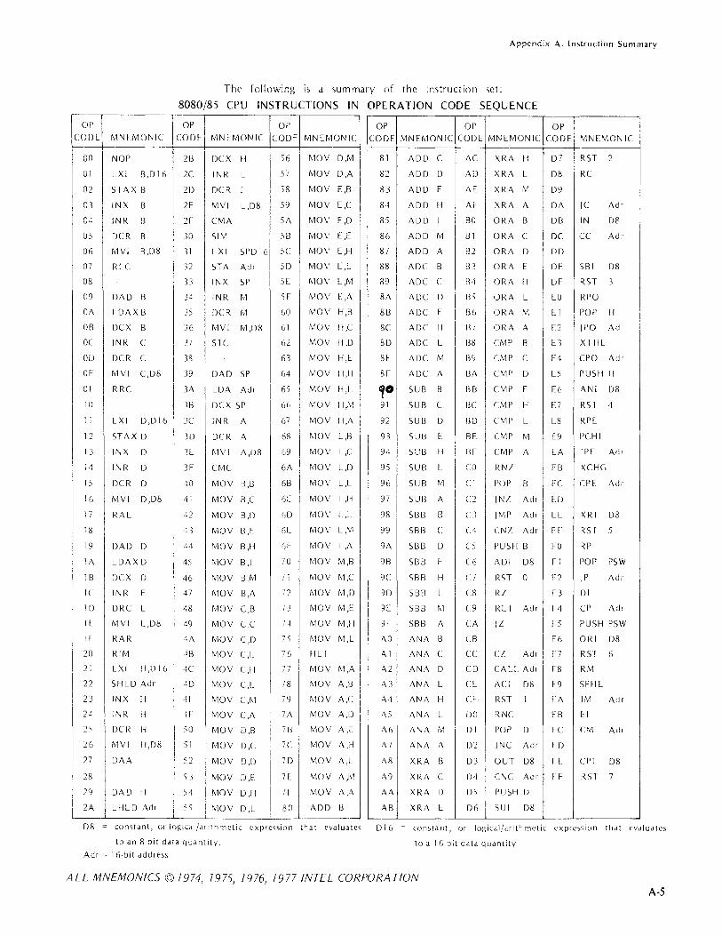
Appendix A. Instrl1ction Sl1mmary
The following is a summary of the instruction set:
8080/85 CPU INSTRUCTIONS IN OPERATION CODE SEQUENCE
~If' OP OP CODE MNEMONIC CODI'. MN EMON IC CODE MNEMONIC
OP CODE
r---00 NOP 2B DCX H 56 MOV D,M 81
CI LXI B,DI6 2C INR L 57 MOV D,A 82
02 ST A X B 2D DCR L 58 MOV E,B 83
03 INX B 2E MVI L,D8 59 MOV E,C 84
04 INR B 2f CMA 'iA MOV E,D 85
05 DCR B 30 SIM 'iB MOV E,E 86
06 MVI B,D8 31 LXI Sf'D 16 5C MOV E,H 87
07 RIC 32 5TA Ad.- 5D MOV E,I 88
08 33 INX SP 5E MOV I'.,M 89
09 DAD B 34 INR M Sf MOV E,A 8A
OA IDAXB 35 DCR M 60 MOV H,B 88
OB DCX B 36 MVI M ,Ilk 61 MOV H,C 8e
OC INR c: 37 STC 62 MOV H,D 8D
OD DCR C 38 63 MOV H,E 81::
01'. MVI CD8 39 DAD SP 64 MOV H,H 8F
Of' RRC 3A LDA Ad, 65 MOV H,L ,0 10 38 DCX SP 66 MOV H,M 91
I I LXI D,D 16 3C INR A 67 MOV H,A 92
12 STAX D 3D DCR A 68 MOV L,B 93
13 INX D 3E MVI A ,[)8 G9 MOV L,C 94
14 INR [) 3f' CMC 6A MOV L,D 95
15 DCR D 10 MOV B,B 6B MOV L,E 96
16 MVI D,D8 ·11 MOV B,C 6C MOV L,H 97
17 RAI 12 MOV B ,I) (,D MOV L,L 98
18 ·13 MOV B,I:: 6l MOV L,M 99
19 DAD D H MOV 13,11 (,1 MOV L ,A 9A
IA LDAX D 4') .\10 V B,L 70 MOV .\1,B 913
IB DCX D 46 MOV B.M C I MOV M,C 9C
IC INR E 47 MOV 8,A 72 ,\10V M,D 9D
II) DRC E 48 MOV C,B 73 MOV M,E. 9E
If MVI tc,D8 49 MOV C,C 74 MOV M,H 9F
If RAR 4A MOV C,D 7'J MOV M,L AD
20 RIM 18 MOV C,r-: 76 HLT Al
21 LXI II ,n I 6 4C MOV C,1i 77 MOV M,A A2
22 SHLD Ad, 4D MOV C,L 78 ."10 V A,B A3
23 INX II ·11:: MOV C,M 79 MOV A,C A4
24 INR H 1f' MOV C,A 7A MOV A,IJ AS
2) DCR H SO MOV D,S 78 MOV A ,I: A6
26 MVI II,D8 S I MOV D,C 7C MOV A,H A7
27 DAA 52 MOV D,D 7D MOV A ,L A8
28 53 MOV D,E IE MOV A ,111 A9
29 DAD H 54 MOV D,H 7F MOV A,A AA
2A LHLD Adr 'is MOV D,L 80 ADD B AB --
D8 = constant, 0' loglcdl/al ithmctic cxpre"ion that evall1ates 016
to an 8 bit data quantity. Adr = 16-bit address
Of' OP MNEMONIC COD I:: MNI::MONIC CODE MNEMONIC
ADD C AC XRA H D7 RST 2
ADD D AD XRA L D8 RC
ADD E AE XRA M D9
ADD H AF XRA A DA IC Adr
ADD L BO ORA B DB IN D8
ADD M 81 ORA C DC CC Ad.-
ADD A B2 ORA D DD
ADC B 83 ORA E DE SBI D8
ADC C 84 ORA II DF RST 3
ADC D 85 ORA L EO RPO
ADC E B6 ORA M EI POP H
ADC H B7 ORA A 1'2 IPO Ad r
ADC l_ 138 eMf' B E3 XTHL
ADC M 89 eMP C E4 CPO Ad.-
ADC A 8A CM]> D E5 I)USH H
SUB B 8B eM!> E [6 ANI D8
SUB C BC eMP H E7 RST 4
SUB D IlD eMf' L 1::8 RPI'.
SUB E 8E CMf' M E9 I'CHL
SU8 II BF CMf' A LA I PE Ad,
SUB l. CO RN! EB XCHG
SUB M CI POP 8 LC ePE Adl
SU13 A C2 IN!' Ad.- [0
S8B B Cl IMP Ad, EE XRI D8
S813 C C4 eN! Ad, [f RST 5
SBB D C5 PUSH B FO RP
SBB L (:Ii ADI D8 Fl POP PSW
S813 H C7 R5T 0 12 IP Ad,
5B13 L C8 R! Fe 3 DI
S813 1\1 C9 REI Adr 14 CP Adr
SBB A CA II 15 PUSH PSW
ANA 13 CB F6 ORI D8
ANA C CC Cl Ad, I' 7 RST 6
ANA D CD CALL Ad, F8 RM
ANA E CI'. ACI D8 F9 SPH L
ANA H CF R5T I fA 1M Adr
ANA L 00 RNC FB U
ANA M j)1 POP D FC eM Ad,
ANA A D2 jNC Ad r fD
XRA B D3 OUT D8 IE el'l D8
XRA C D4 CNC Adr F f' RST 7
XRA D DS PUSH D
XRA [ D6 SUI D8
constant, or logical/dfithmctic cxplc,sion that evall1ates
to a 16 bit data quantity
ALL MNEMONICS © 7974,7975,7976, 7977 INTEL CORPORATION A-5

Appendix A. Instruction Summary
Instructioll Set Guide
/\\)1)
.!\DC
SUB
SBB
AN/\
XRA OR/,
eMf'
RlC;M S
RLC RAL RRC RAR CMA DAA
INR} DCR RECM g
ADI
ACI
SUI
5131 Dg
AN I
XRI
CRI I (PI )
1+,cc~ULAl6R[--FLACs=:Jf~~ CMC HIC;II __ ~_()_W_~ MOV RECMg,RlGM g. L __ .-_B- __ u+ ____ ._C =:Jg~S} REG I G SPH1,_~CK : POINl ER 1-:]
I C---~---.L---~--~XCL1(- PCl
J1L--1 PROC;RA~UNTLR f.--RSI
LXI REG\(i,D IGi- .- H r----- C- -~/ I J __ t ,_._ L..___ -- ,-- J T
I J~1P CALL RtT
I JC JNCl CC CNC RC RNCl
r XTHL-l )1 JNI CI CNl A R! RNI
~ ______ U~ll)1 -__ ; __ 1_ :~E :~~JI ,\ 1(, ~~E ~~~ 1 (, ~;F ~~oJ r----~, STHD J AIG IN Ps OUT Ps CONTROL
LDAX'l BC DE ~~ ST Axf ' INPUT OUTPUT INSTRUCTIONS MEMORY
PORTS I PORTS RST
LDA} I NOP S T A ;\ I G , i I H U
~--------LL rUSH \ ~:IM} MVI DS
MOV REGMS,RLGM S
CODt
Dg
A16 Ps REG IG DIG
STACK POP .f B,D,H,P5W RIM
SOSS ON L Y
MEANING
The operdnd nld'~ ,pcci'y olle of the g-bit rcgi<,lcr~ A,B,C,D,E,H, or Lor M (a n1l'm"IY
refcrcilce via the I G-bit dddrc~,> in the Hand L regi,tcr,). The MOV in<;lruction, which
cdl\<, fur two operdllLb, can ,>pccify M lUI' only onc of it<, upcr,!nd,>.
De,>igndte'> Sbit immed ate operand.
De,>igndtc'> a IS-bit add·c,>,.
Dc~igndte" Jtl S-bit pm numbcl-.
Designdtcs d ;G-bit regi,ter Pdir (B&C,D&E,H&L,or SP).
De,>ignJtC'" d 16 -bit imrledidte operdnd.
ALL MNEMONICS © 7974, 7975, 7976, 7977 INTEL CORPORA TlON
A-6

APPENDIIX B. ASSEMBLER DIRECTIVE SUMMARY
A,>sembler directive'> arc summdri/ed alphdbeticdlly in thi, appendix. The following tClm, Jre u'>cd to dcscribe
the contents of directive field,>.
NOTATION
Term
Exprc"ion
List
Name
Null
Opldb
ParJ meter
String
Text
Interpretation
Numerical exprcs,>ion evaluated during d,;,embly; mu,t eVdluJte
to 8 or 16 bits depending on directive i"ued.
Seric'> of symbolic vdlue, or cxpres,>ioll'>, sepdrated by comma'>.
Symbol nJme termindted by a ,pace.
Field mu'>t be empty or dn errol re,ulh.
Optiondl Idbel; must be terminJted by a colon.
Dummy pJrameters arc ,ymbul, holding the plcice of actual
pdrdmcter'> (,>ymbolic values or cxpre,,>ioll'» .,pecified elsewhere
in the progrdm.
Series of any ASCII chJrJcter'>, sUIToundcd by single quute mJrks.
Single quote within string is ,>hown d'> two con'>ecutivc '>ingle quutc,>.
Series of ASCII character'>.
Mdcro definitions dlld calls dllow the U'>lO of the '>peciJI characters li,ted below.
Character
&
< )
FUl7clio 17
Ampers;iIld. Used to concatendte '>ymbol,.
Angle bracket,>. Used to delimit text, ,uch d'> hb, thJt contdin
other delimiter,>.
Double ,>emicolon. U"cd befole a cummcnt in d mdcro definition
to prevent inciu,>ion of the comment in edch Illdcro l'xpdmi()ll.
Excldmdtion puint (e.,cape chal Jcter). Pldccd hefore .I delimitel
to be pas,cd cl'> a literal in .111 actual pdl"dmetel. 10 pa" .I litn,lI
excldmdtion point, i'>'>lle 'II.'
Pel·cent ,ign. Precede, dctlldl pdldmetel' to be l'valudtcd imn1l'dic!tcly
when the macro i'> edled.
ALL MNEMONICS © 7974, 7975, 7976, 7977 INTEL CORPORI1T10N
8-1

Appendix B. Assembler Directive Summary
SUMMARY OF DIRECTIVES
FORMAT
Label Opcode Operand(s)
oplab: DB exp(s) or string(s)
oplab: DS expression
oplab: DW exp(s) or str ng(,)
oplab: ELSE null
opldb: END c xpre,>,ion
oplab: ENDIF null
EQU
opldb: IF expres'>lon
oplab: ORG
ndme SET exprC,»loll
MACRO DIRECTIVES
FORMAT
Label Opcode Operund(s)
null ENDM null
oplab: EXITM null
oplab: IRP dummy par.lm,<list>
FUNCTION
Define 8-bit data bytc(s). Expressions must eVdluatc
to olle byte.
Re')erve data storage area of specified length.
Define 16-bit data word(s). Strings limited to 1-2
characters.
Conditional assembly. Code between ELSE and
ENDIF directive') is assembled if expression in IF
clau,e i, F/,LSE. (See IF.)
Terminate ,J'>scmbler pa'>'>. Mu'>t be last ,tatement of
program. Program execution starts at 'exp,' if present;
othcrwi')e, dt locdtion O.
Termindte conditional ds,embly block.
Define ,>ymhol 'n,lme' with value 'exp.' Symbol i'> not
rcdefindhlc.
A.,,>cmhle code hetween IF and following ELSE or
ENDIF dircLlivc if 'exp' i'> true.
Set locatioll c()unter to 'expre,>,>ion.'
Defillc .,ymbol 'n.lme' with v,ilue 'cxprc'>Si()n.'
Svmbol Cd'l be rL'det illL'l1.
FUNCTION
Terminate macro definition.
Alternate terminator of mdcro definition. (See ENDM.)
Repeat instruction '>equence, substituting one character
form 'list' for 'dummy param' in each iteration.
ALL MNEMONIC5©7974, 7975, 1976, 7977 INTEL CORPORA TlON
8-2

FORMAT
Label Opcode
oplab: IRPC
null LOCAL
name MACRO
oplab: REPT
RELOCATION DIRECTIVES
FORMAT
Label Opcode
oplab: ASEG
oplab: CSEG
oplab: DSEG
oplab: EXTRN
oplab: NAME
oplab: PUBLIC
oplab: STKLN
Operand(s)
dummy param,text
label name (s)
dummy param(s)
expression
Operand(s)
null
bou ndary specification
boundary specification
name(s)
module-name
name(s)
expression
Appendix B. Assembler Directive Summary
FUNCTION
Repeat instruction sequence, ~ubstituting one character from 'text' for 'dummy param' in each
iteration.
Specify label(s) in macro definition to have local
scope.
Define macro 'name' and dummy parameter(s) to be
used in macro definition.
Repeat REPT block 'expression' times.
FUNCTION
Assemble subsequent instructions and data in the
absolute mode.
Assemble subsequent instructions and data in the
relocatable mode using the code location counter.
Assemble subsequent instructions and data in the relocatable mode using the data location counter.
Identify symbols used in this program module but
defined in a different module.
Assigns a name to the program module.
Identify symbols defined in this module that are to
be available to other modules.
Specify the number of bytes to be reserved for the
stack for this module.
ALL MNEMONICS©7974, 7975, 7976, 7977 INTEL CORPORA TlON
8-3


APPENDIX C. ASCII CHARACTER SET
ASCII CODES
The 8080 and 8085 use the ,>even-tit ASCII code, with the high-order eighth bit (parity bit) alwJY, rc'>et.
GRAPHIC OR ASCII GRAPHIC OR ASCII GRAPHIC OR ASCII CONTROL (HEXADECIMAL) CONTROL (HEXADECIMAL) CONTROL (HEXADECIMAL)
NUL 00 + 2B V 56 SOH 0 1 2C W 57 STX 02 2D X 58 ETX 03 2E Y 59 EOT 04 2F Z 5A ENO 05 0 30 [ 5B ACK 06 31 5C BEL 07 2 32 5D BS 08 3 33 1\ ( 11 5E HT 09 4 34 - (~I 5F LF DA 5 35 60 VT DB 6 36 a 61 FF DC 7 37 iJ 62 CR OD 8 38 c 63 SO DE 9 39 d 64 SI OF 3A f' 65 DLE 10 38 66 DCl (X-ON) 11 '- 3C lj 67 DC2 (TAPE I 12 3D il 68 DC3 (X-OFFI 13 > 3E 69 DC4 C~A-PB 1,1 3F 6A NAK 15 Cci~ 40 k 6B SYN lG A 41 6C ETB 17 B 42 rT1 6D CAN 18 C 43 II 6E EM 1 ~J D 44 CJ 6F SU B lA E 45 p 70 ESC Hl F 46 q 71 FS lC G 47 72 GS 10 H 48 73 RS 1 E 49 74 US 1 F J 4A II 75 SP 20 K 4B v 76
21 L 4C IN 77
22 M 40 x 78 ::::; 23 N 4E Y 79 S 24 0 4F 7A Cl,b 2:) P 50 7B & 26 0 51 7C
27 R 52 I (AL T MODEl 70 28 S 53 7E 29 T 54 DEL (RUB OUTI n 2A U 55
C-1


AIPPENDIX D.
BINARY -DECIMAL-HEXA.DECIMAL CONVERSION TABLES.
D·'

Appendix D. Binary·Decimal·Hexadecimal Conversion Tal)les
POWERS OF TWO
1 0 10 2 1 0.5 4 2 0.25 8 3 0.125
16 4 0.062 5 32 5 0.031 25 64 6 0.015 625
128 0.007 812 5
256 512
1 024 2 048
8 0.003 906 25 9 0001 953 125
10 0000 976 562 5 11 0000 488 281 25
4 096 12 0000 244 140 625 8 192 13 0000 122 070 312 5
16 )84 14 0000 061 035 156 25 32768150000030517578125
65 536 16 0000 015 258 789 062 5 131 072 17 0000 007 629 394 531 25 262 144 18 0000 003 814 697 265 625 524288 190000001907348632812 5
1 048 576 20 0000 000 953 674 316 406 25 2 097 152 21 0000 000 476 837 158 203 125 4 194 304 22 0000 000 238 418 579 101 562 5 8 388 608 23 0000 000 119 209 289 550 781 25
16 777 216 24 0000 000 059 604 644 775 390 625 33 554 432 25 0000 000 029 802 322 387 695 312 5 67 108 864 26 0000 000 014 901 161 193 847 656 25
134 217 728 27 0000 000 007 450 580 596 923 828 125
268 435 456 28 0000 000 003 725 :290 298 461 914 062 5 536 870 912 29 0000 000 001 862 E45 149 230 957 031 25
1 073 741 824 30 0000 000 000 931 "22 574 615 478 515 625 2 147 483 648 31 0000 000 000 465 E61 287 307 739 257 812 5
4 294 967 296 32 0000 000 000 232 EJO 643 653 869 628 906 25 8 589 934 592 33 0000 000 000 116 ~ 15 321 826 934 814 453 12:)
17179869184340000000000058 <07 66091346740722656;' 5 34 359 738 368 35 0000 000 000 029 103 830 456 733 703 613 28' 25
68 719 476 736 36 0000 000 000 014 :,51 915 228 366 851 806 640 625 137 438 953 472 37 0000 000 000 007 ?75 957 614 183 425 903 320 312 5 274 877 906 944 38 0000 000 000 003 637 978 807 091 712 951 660 156 25 549 755 813 888 39 0000 000 000 001 818 989 403 545 856 475 830 078 125
1 099 511 627 776 40 0000 000 000 000 909 494 701 772 928 237 915 039 062 5 2 199 023 255 :'52 41 0000 000 000 000 "5.4 747 350 886 464 118 95" 519 531 25 4 398046511104420000000000000;>27373675443232059478 759 765625 8 796 093 022 208 43 0000 000 000 000 ·13 686 837 721 616 029 739 379 882 812 5
17592186044416440000 000 000 000 056 843 418 860 808014869689941406 25 35 184 372 088 832 45 0000 000 000 000 028 421 709 430 404 007 43 d 844 970 703 125 70 368 744 177 664 46 0000 000 000 000 014 210 854 715 202 003 717 422 485 351 562 5
140 737 488 355 328 47 0 000 000 000 000 n07 105 427 357 601 001 85H 711 242 675 781 25
281 474 976 710 656 48 0000 000 000 000 n03 552 713 678 800 500 929 355 621 337 890 625 562 949 953 471 312 49 0000 000 000 000 001 776 356 839 400 250 4f>" 677 810 668 945 312 5
1 125 899 906 842 674 50 0000 000 000 000 ODD 888 178 419 700 125 23:2 338 905 334 472 656 25 7 251 799 813685 248 51 0000 000 000 000 000 444 089 209 850 062 616 169 452 667 236 j28 125
4 503 599 627 370 496 52 0000 000 000 000 1)00 222 044 604 925 031 3013 084 726 333 618 164 062 5 9 007 199 254 740 992 53 0000 000 000 000 1)00 111 022 302 462 515 654 042 363 166 809 082 031 25
18 014 398 509 481 984 54 0000 000 000 000 1)00 055 511 151 231 257 827 021 181 583 404 541 015 625 36 028 797 018 963 968 55 0 000 000 000 000 ')00 027 755 575 615 628 913 510 590 791 702 270 507 812 5
72 057 594 037 927 936 56 0000 000 000 000 ')00 013 877 787 807 814 456 755 295 3% 851 135 253 906 25 144 115 188 075 855 872 57 0000 000 000 000 ')00 006 938 893 903 907 228 377 64 7 697 925 567 676 950 125 288 230 376 151 711 744 58 0000 000 000 000 ')00 003 469 446 951 953 614 188 823 848 962 783 813 476 562 5 576 460 752 303 423 488 59 0000 000 000 000 ')00 ')01 734 723 475 976 80 7 094 411 924 481 391 906 738 281 25
1 152 921 504 606 846 976 60 0000 000 000 000 )00 000 867 361 737 988 403 547 205 962 240 695 953 369 140 625 2 305 843 009 213 693 952 61 0000 000 000 000 )00 000 433 680 868 994 201 773 602 981 120 347 976 684 570 312 5 4 611 686 018 427 387 904 67 0000 000 000 000 )00 000 216 840 434 497 100886801 490 560 173 988 342 285 156 25 9 223 372 036 854 775 808 63 0000 000 000 000 )00 000 108 420 217 248 550443 400 745 280086 994 171 142 578 125
D-2

Appendix D. Binary-Decimal-Hexadecimal Conversion Tables
POWERS OF 16 (IN BASE 10)
16n n 16"
1 0 0.10000 00000 00000 00000 X 10
16 1 0.62500 00000 00000 00000 X 10- 1
256 2 0.39062 50000 00000 00000 X 10-2
4 096 3 0.24414 06250 00000 00000 X 10-3
65 536 4 0.15258 78906 25000 00000 x 10-4
048 576 5 0.95367 43164 06250 00000 x 10-1>
16 777 216 6 0.59604 64477 53906 25000 x 10- 7
268 435 456 7 0.37252 90298 46191 40625 x 10-8
4 294 967 296 8 0.23283 06436 53869 62891 x 10-9
68 719 476 736 9 0.14551 91b22 83668 51807 x 10- 10
099 511 627 776 10 090949 47017 72928 23792 x 10- 12
17 592 186 044 416 11 0.56843 41886 08080 14.870 x 10- 13
281 474 976 710 656 12 0.35527 13678 80050 09294 x 10- 14
4 503 599 627 370 496 13 0.22204 46049 25031 30808 x 10- IS
72 057 594 037 927 936 14 o 13877 78780 78144 56755 x 10- 11>
1 152 921 504 606 846 976 15 0.86736 17379 88403 54721 x 10- 11\
POWERS OF 10 (IN BASE 16)
10n
n lO- n
0 1.0000 0000 0000 0000
A 1 0.1999 9999 9999 999A 64 2 0.28F5 C28F 5C28 F5C3 16 1
x
3E8 3 0.4189 374B C6A7 EF9E x 16 2
2710 4 0.680E: 8BAC 710C B296 x 16 -J
1 86AO 5 O.A 7C~) AC47 1 B47 8423 x 16 4
F 4240 6 0.10C6 F7AO B5EO 8037 x 16 -4
98 9680 7 0_lAO? F29A BCAF 4858 x 16 -5
5F5 El00 8 0.2AF~: lDC4 6118 73BF x 16 -/,
3B9A CAOO 9 0.44B8 2FAO 9B5A 52CC x 16 -,
2 540B E400 10 0.60F~. 7F67 SE F6 EAOF x 16 -1\
17 4876 E800 11 O.AFEB FFOB CB24 AAFF x 16 -9
E8 04A5 1000 12 0.1197 9981 20EA 1119 x 16 -9
918 4E72 AooO 13 0.lC25 C268 4976 81C2 x 16 -10
5AF3 107A 4000 14 0.2009 3700 4257 3604 x 16 -I 1
3 807E A4C6 8000 15 0.480E BElB 9058 5660 x 16 - 12
23 8652 6FCl 0000 16 0.734A CA5F 6226 FOAE x 16 - J3
163 4578 508A 0000 17 0.B877 AA32 36A4 B449 x 16 -14
OEO B6B3 A764 0000 18 0.1272 5001 0243 ABAl x 16 - 14
8AC7 2304 89E8 0000 19 0.1083 C94F B602 AC35 x 16 -IS
0-3

Appendix D. Binary·Decimal·Hexadecimal Conversion Tabl,~s
HEXADECIMAL-DECIMAL INTEGER CONVERSION
The table below provides for direct conversions between hexadecimal integers in the range O·FFF and decimal integers in the range 0-4095. For conversion of larger integers, the table values may be added to the following figures:
Hexadecimal !Decimal Hexadecimal Decimal
01000 4096 20000 131072
02000 8192 30000 196608 03000 12288 40000 262 144
04000 16384 50000 327680 05000 20480 60000 393216
06000 24576 70000 458 752
07000 28672 80000 524288
08000 32768 90000 589824
09000 36864 AO 000 655360
OA 000 40960 BO 000 720896
OB 000 45056 CO 000 786432
OC 000 49152 DO 000 851 968
00000 53248 EO 000 917 504
OE 000 57344 FO 000 983040
OF 000 61440 100000 1 048576
10000 65536 200000 2097 152
11000 69632 300000 3 145728
12000 73728 400000 4 194304
13000 77 824 500000 5242880
14000 81 920 600000 6291 456
15000 86016 700000 7340032
16000 90112 800000 8388608 17000 94208 900000 9437184
18000 98304 AOO 000 10485760 19000 102400 BOO 000 11 534336 1A 000 106496 COO 000 12582912 1B 000 110592 000000 13631488 1C 000 114688 EOO 000 14680064 10000 118784 FOO 000 15728640 1 E 000 122 880 1 000000 16777 216 1 F 000 126976 2000000 33554432
0 1 2 3 4 5 6 7 8 9 A B C 0 E F
000 0000 0001 0002 0003 0004 0005 0006 0007 0008 0009 0010 0011 0012 0013 0014 0015
010 0016 0017 0018 0019 0020 0021 0022 0023 0024 OOni 0026 0027 0028 0029 0030 0031 020 0032 0033 0034 0035 0036 0037 0038 0039 0040 0041 0042 0043 0044 0045 0046 0047 030 0048 0049 0050 0051 0052 0053 0054 0055 0056 0057 0058 0059 0060 0061 0062 0063
040 0064 0065 0066 0067 0068 0069 0070 0071 0072 0073 0074 0075 0076 0077 0078 0079
050 0080 0081 0082 0083 0084 0085 0086 0087 0088 008H 0090 0091 0092 0093 0094 0095
060 0096 0097 0098 0099 0100 0101 0102 0103 0104 010!; 0106 0107 0108 0109 0110 0111
070 0112 0113 0114 0115 0116 0117 0118 0119 0120 012'1 0122 0123 0124 0125 0126 0127
080 0128 0129 0130 0131 0132 0133 0134 0135 0136 0137 0138 0139 0140 0141 0142 0143
090 0144 0145 0146 0147 0148 0149 0150 0151 0152 0153 0154 0155 0156 0157 0158 0159
OAO 0160 0161 0162 0163 0164 0165 0166 0167 0168 016B 0170 0171 0172 0173 0174 0175
OBO 0176 0177 0178 0179 0180 0181 0182 0183 0184 0185 0186 0187 0188 0189 0190 0191
OCO 0192 0193 0194 0195 0196 0197 0198 0199 0200 0201 0202 0203 0204 0205 0206 0207
000 0208 0209 0210 0211 0212 0213 0214 0215 0216 0217 0218 0219 0220 0221 0222 0223
OEO 0224 0225 0226 0227 0228 0229 0230 0231 0232 0233 0234 0235 0236 0237 0238 0239
OFO 0240 0241 0242 0243 0244 0245 0246 0247 0248 0249 0250 0251 0252 0253 0254 0255
0-4

Appendix D. Binary-Decimal-Hexadecimal Conversion Tables
HEXADECIMAL-DECIMAL INTEGER CONVERSION (Cant'd)
0 1 2 3 4 5 6 7 8 9 A B C 0 E F
100 0256 0257 0258 0259 0260 0261 0262 0263 0264 0265 02Ei6 0267 0268 0269 0270 0271 110 0272 0273 0274 0275 0276 0277 0278 0279 0280 0281 0282 0283 0284 0285 0286 0287 120 0288 0289 0290 0291 0292 0293 0294 0295 0296 0297 0298 0299 0300 0301 0302 0303 130 0304 0305 0306 0307 0308 0309 0310 0311 0312 0313 0314 0315 0316 0317 0318 0319
140 0320 0321 0322 0323 0324 0325 0326 0327 0328 0329 033:0 0331 0331 0333 0334 0335 150 0336 0337 0338 0339 0340 0341 0342 0343 0344 0345 0346 0347 0348 0349 0350 0351 160 0352 0353 0354 0355 0356 0357 0358 0359 0360 0361 036,2 0363 0364 0365 0366 0367 170 0368 0369 0370 0371 0372 0373 0374 0375 0376 0377 0378 0379 0380 0381 0382 0383
180 0384 0385 0386 0387 0381:l 0389 0390 0391 0392 0393 0394 0395 0396 0397 0398 0399 190 0400 0401 0402 0403 0404 0405 0406 0407 0408 0409 0410 0411 0412 0413 0414 0415 lAO 0416 0417 0418 0419 0420 0421 0422 0423 0424 0425 0426 0427 0428 0429 0430 0431 180 0432 0433 0434 0435 0436 0437 0438 0439 0440 0441 0442 0443 0444 0445 0446 0447
lCO 0448 0449 0450 0451 0452 0453 0454 0455 0456 0457 0458 0459 0460 0461 0462 0463 100 0464 0465 0466 0467 0468 0469 0470 0471 0472 0473 0474 0475 0476 0477 0478 0479 lEO 0480 0481 0482 0483 0484 0485 0486 0487 0488 0489 0490 0491 0492 0493 0494 0495 1 FO 0496 0497 0498 0499 0500 0501 0502 0503 0504 0505 0506 050'/ 0508 0509 0510 0511
200 0512 0513 0514 0515 0516 0517 0518 0519 0520 0521 0522 0523 0524 0525 0526 0527 210 0528 0529 0530 0531 0532 0533 0534 0535 0536 0537 0538 0539 0540 0541 0542 0543 220 0544 0545 0546 0547 0548 0549 0550 0551 0552 0553 0554 0555 0556 0557 0558 0559 230 0560 0561 0562 0563 0564 0565 0566 0567 0568 0569 0570 0571 0572 0573 0574 0575
240 0576 0577 0578 0579 0580 0581 0582 0583 0584 0585 0586 0587 0588 0589 0590 0591 250 0592 0593 0594 0595 0596 0597 0598 0599 0600 0601 0602 0603 0604 0605 0606 0607 260 0608 0609 0610 0611 0612 0613 0614 0615 0616 0617 0618 0619 0620 0621 0622 0623 270 0624 0625 0626 0627 0628 0629 0630 0631 0632 0633 0634 0635 0636 0637 0638 0639
280 0640 0641 0642 0643 0644 0645 0646 0647 0648 0649 0650 0651 0652 0653 0654 0655 290 0656 0657 0658 0659 0660 0661 0662 0663 0664 0665 0666 0667 0668 0669 0670 0671
·2AO 0672 0673 0674 0675 0676 0677 0678 0679 0680 0681 0682 0683 0684 0685 0686 0687 ! ::: 0688 0689 0690 0691 0692 0693 0694 0695 0696 0697 0698 0699 0700 0701 0702 0703
0704 0705 0706 0707 0708 0709 0710 0711 0712 0713 0714 0715 0716 0717 0718 0719 200 0720 0721 0722 0723 0724 0725 0726 0727 0728 0729 0730 0731 0732 0733 0734 0735 2EO 0736 0737 0738 0739 0740 0741 0742 0743 0744 0745 0746 0747 0748 0749 0750 0751 2FO 0752 0753 0754 0755 0756 0757 0758 0759 0760 0761 076,2 0763 0764 0765 0766 0767
300 0768 0769 0770 0771 0772 0773 0774 0775 0776 0777 0778 0779 0780 0781 0782 0783 310 0784 0785 0786 0787 0788 0789 0790 0791 0792 0793 0794 0795 0796 0797 0798 0799 320 0800 0301 0802 0803 0804 0805 0806 0807 0808 0809 0810 0811 0812 0813 0814 0815 330 0816 0817 0818 0819 0820 0821 0822 0823 0824 0825 0826 0827 0828 0829 0830 0831
340 0832 0833 0834 0835 0836 0837 0838 0839 0840 0841 0842 0843 0844 0845 0846 0847 350 0848 0849 0850 0851 0852 0853 0854 0855 0856 0857 0858 0859 0860 0861 0862 0863 360 0864 0865 0866 0867 0868 0869 0870 0871 0872 0873 0874 0875 0876 0877 0878 0879 370 0880 0881 0882 0883 0884 0885 0886 0887 0888 0889 0890 0891 0892 0893 0894 0895
380 0896 0897 0898 0899 0900 0901 0902 0903 0904 0905 0906 0907 0908 0909 0910 0911 390 0212 0913 0914 0915 0916 0917 0918 0919 0920 0921 092'2 0923 0924 0925 0926 0927
,3AO 0928 0929 0930 0931 0932 0933 0934 0935 0936 0937 0938 0939 0940 0941 0942 0943 380 0944 0945 0946 0947 0948 0949 0950 0951 0952 0953 0954 0955 0956 0957 0958 0959
3CO 0960 0961 0962 0963 0964 0965 0966 0967 0968 0969 097'0 0971 0972 0973 0974 0975 300 0976 0977 0978 0979 0980 0981 0982 0983 0984 0985 0986 0987 0988 0989 0990 0991
t 3EO 0992 0993 0994 0995 0996 0997 0998 0999 1000 1001 1002 1003 1004 1005 1006 1007 3FO 1008 1009 1010 1011 1012 1013 1014 1015 1016 1017 1018 1019 1020 1021 1022 1023
D-5

Appendix D_ Binary-Decimal-Hexadecimal Conversion Tables
HEXADECIMAL-DEC MAL I~JTEGER CONVERSION (Cant'd)
, ----------~-
0 1 2 3 4 5 6 7 8 9 A B C D E F
400 1024 1025 1026 1027 1028 1028 1030 1031 1032 1033 1034 1035 1036 1037 1038 1039 410 1040 1041 1042 1043 1044 1045 1046 1047 1048 1049 1050 1051 1052 1053 1054 1055 420 1056 1057 1058 1059 1060 1061 1062 1063 1064 106~) 1066 1067 1068 1069 1070 1071 430 1072 1073 1074 1075 1076 1077 1078 1079 1080 10811 1082 1083 1084 1085 1086 1087
440 1088 1089 1090 1091 1092 1093 1094 1095 1096 1097 1098 1099 1100 1101 1102 1103 450 1104 1105 1106 1107 1108 1109 1110 1111 1112 1113 1114 1115 1116 1117 1118 1119 460 1120 1121 1122 1123 1124 1125 1126 1127 1128 1129 1130 1131 1132 1133 1134 1135 470 1136 1137 1138 1139 1140 1141 1142 1143 1144 114!; 1146 1147 1148 1149 1150 1151
480 1152 1153 1154 1155 1156 1157 1158 1159 1160 116-1 1162 1163 1164 1165 1166 1167 490 1168 1169 1170 1171 1172 1173 1174 1175 1176 1117 1178 1179 1180 1181 1182 1183 4AO 1184 1185 1186 1187 1188 1189 1190 1191 1192 119:3 1194 1195 1196 1197 1198 1199 480 1200 1201 1202 1203 1204 1205 1206 1207 1208 1209 1210 1211 1212 1213 1214 1215
4CO 1216 1217 1218 1219 1220 1221 1222 1223 1224 122!) 1226 1227 1228 1229 1230 1231 4DO 1232 1233 1234 1235 1236 1237 1238 1239 1240 1241 1242 1243 1244 1245 1246 1247 4EO 1248 1249 1250 1251 1252 1253 1254 1255 1256 1257 1258 1259 1260 1261 1262 1263 4FO 1264 1265 1266 1267 1268 1269 1270 1271 1272 1273 1274 1275 1276 1277 1278 1279
500 1280 1281 1282 1283 1284 1285 1286 1287 1288 1289 1290 1291 1292 1293 1294 1295 510 1296 1297 1298 1299 1300 1301 1302 1303 1304 1305 1306 1307 1308 1309 1310 1311 520 1312 1313 1314 1315 1316 1317 1318 1319 1320 1321 1322 1323 1324 1325 1326 1327 530 1328 1329 1330 1331 1332 1333 1334 1335 1336 1337 1338 1339 1340 1341 1342 1343
540 1344 1345 1346 1347 1348 1349 1350 1351 1352 1353 1354 1355 1356 1357 1358 1359 550 1360 1361 1362 1363 1364 1365 1366 1367 1368 1369 1370 1371 1372 1373 1374 1375 560 1376 1377 1378 1379 1380 1381 1382 1383 1384 1385 1386 1387 1388 1389 1390 1391 570 1392 1393 1394 1395 1396 1397 1398 1399 1400 1401 1402 1403 1404 1405 1406 1407
580 1408 1409 1410 1411 1412 1413 i414 1415 1416 1417 1418 1419 1420 1421 1422 1423 590 1424 1425 1426 1427 1428 1429 1430 1431 1432 1433 1434 1435 1436 1437 1438 1439 5AO 1440 1441 1442 1443 1444 1445 1446 1447 1448 1449 1450 1451 1452 1453 1454 1455 580 1456 1457 1458 1459 1460 1461 1462 1463 1464 1465 1466 1467 1468 1469 1470 1471
5CO 1472 1473 1474 1475 1476 1477 1478 1479 1480 1481 1482 1483 1484 1485 1486 1487 5DO 1488 1489 1490 1491 1492 1493 1494 1495 1496 1497 1498 1499 1500 1501 1502 1503 5EO 1504 1505 1506 1507 1508 1509 1510 1511 1512 1513 1514 1515 1516 1517 1518 1519 5FO 1520 1521 1522 1523 1524 1525 1526 1527 1528 1529 1530 1531 1532 1533 1534 1535
600 1536 1537 1538 1539 1540 1541 154L 1543 1544 1545 1546 1547 1548 1549 1550 1551 610 1552 1553 1554 1555 1556 1557 1558 1559 1560 1561 1562 1563 1564 1565 1566 1567 620 1568 1569 1570 1571 1572 1573 1574 1575 1576 1577 1578 1579 1580 1581 1582 1583 630 1584 1585 1586 1587 1588 1589 1590 1591 1592 15913 1594 1595 1596 1597 1598 1599
640 1600 1601 1602 1603 1604 1605 1606 1607 1608 1609 1610 1611 1612 1613 1614 1615 650 1616 1617 1618 1619 1620 1621 1622 1623 1624 1625 1626 1627 1628 1629 1630 1631 660 1632 1633 1634 1635 1636 1637 1638 1639 1640 1641 1642 1643 1644 1645 1646 1647 670 1648 1649 1650 1651 1652 1653 1654 1655 1656 16~i7 1658 1659 1660 1661 1662 1663
680 1664 1665 1666 1667 1668 1669 1670 1671 1672 1673 1674 1675 1676 1677 1678 1679 690 1680 1681 1682 1683 1684 1685 1686 1687 1688 1689 1690 1691 1692 1693 1694 1695 6AO 1696 1697 1698 1699 1 700 1701 1702 1703 1704 1705 1706 1707 1708 1709 1710 1711 680 1712 1713 1714 1715 1716 1717 1:718 1719 1720 1721 1722 1723 1724 1725 1726 1727
6CO 1728 1729 1730 1731 1732 1733 1734 1735 1736 17:17 1738 1739 1740 1741 1742 1743 600 1744 1745 1746 1747 1748 1749 1750 1751 1752 17!)3 1754 1755 1756 1757 1758 1759 6EO 1760 1761 1762 1763 1764 1765 1766 1767 1768 171)9 1770 1771 1772 1773 1774 1775 6FO 1776 1777 1778 1779 1780 1781 1782 1783 1784 1785 1786 1787 1788 1789 1790 1791
D-6

0 1
700 1792 1793 7110 1808 1809 no 1824 1825 7:10 1840 1841
740 1856 1857 7!)() 1872 1873 7ElO 1888 1889 no 1904 1905
7BO 1920 1921 790 1936 1937 7AO 1952 1953 7BO 1968 1969
7eO 1984 1985 mo 2000 2001 7EO 2016 2017 71=0 2032 2033
800 2048 2049 8'10 2064 2065 820 2080 2081 8:30 2096 2097
840 2112 2113 8!50 2128 2129 ali 0 2144 2145 870 2160 2161
880 2176 2177 890 2192 2193 8l .. 0 2208 2209 8130 2224 2225
8CO 2240 2241 8DO 2256 2257 8EO 2272 2273 8FO 2288 2289
900 2304 2305 910 2320 2321 920 2336 2337 930 2352 2353
940 2368 2369 9!>O 2384 2385 960 2400 2401 970 2416 2417
980 2432 2433 990 2448 2449 9AO 2464 2465 9BO 2480 2481
9CO 2496 2497 900 2512 2513 9EO 2528 2529 9FO 2544 2545
Appendix D. Binary·Decimal·HexdClecimal Conversion Tables
HEXADECIMAL-DECIM.l~L INTEGER CONVERSION (Cant'd)
2 3 4 5
1794 1795 1796 1797 1810 1811 1812 1813 1826 1827 1828 1829 1842 1843 1844 1845
1858 1859 1860 1861 1874 1875 1876 1877 1890 1891 1892 1893 1906 1907 1908 1909
1922 1923 1924 1925 1938 1939 1940 1941
1954 1955 1956 1957
1970 1971 1972 1973
1986 1987 1988 1989
2002 2003 2004 2005
2018 2019 2020 2021
2034 2035 2036 2037
2050 2051 2052 2053
2066 2067 2068 2069
2082 2083 2084 2085
2098 2099 2100 2101
2114 2115 2116 21 17
2130 2131 2132 2133
2146 2147 2148 2149
2162 2163 2164 2165
2178 2179 2180 2181 2194 2195 2196 2197 2210 221 I 2212 2213 2226 2227 2228 2229
2242 2243 2244 2245
2258 2259 2260 2261 2274 2275 2276 2277
2290 2291 2292 2293
2306 2307 2308 2309 2322 2323 2324 2325 2338 2339 2340 2341 2354 2355 2356 2357
2370 2371 2372 2373 2386 2387 2388 2389 2402 2403 2404 2405 2418 2419 2420 2421
2434 2435 2436 2437 24 !>O 2451 2452 2453 2466 2467 2468 2469 2482 2483 2484 2485
2498 2499 2500 2!>O1 2514 2515 2516 2517 2530 2531 2532 2533 2546 2547 2548 2549
Ii
~8
14 17 18 18: 30 IS. $6
18 18 18 19
132 78 94 10
:26 19 19.
19 19
12 !i8 "74
HO 19 201 20 20
)6 :12 :18
20 20 20 21
!)4 70
U6 02
18 :14 !iO
21 21 21 21 fl6
21 21 22 22
22 22 22 22
23 23 23 23
23 23 24 24
112 !l8 14
:10
·16 li2 78 !l4
10 :l6
·'2 '58
74 ~ )6
22
24 24 24 24
38 54 70 B6
25 25 25 25
02 18 34 !>O
7 8
1799 1800 1815 1816 1831 1832 1847 1848
1863 1864 1879 1880 1895 1896 191 I 1912
1927 1928 1943 1944 1959 1960 1975 1976
1991 1992 2007 2008 2023 2024 2039 2040
2055 2056 2071 2072 2087 2088 2103 2104
2119 2120 2135 2136 2151 2152 2167 2168
2183 2184 2199 2200 2215 2216 2231 2232
2247 2248 2263 2264 2279 2280 2295 2296
231 I 2312 2327 2328 2343 2344 2359 2360
2375 2376 2391 2392 2407 2408 2423 2424
2439 2440 2455 2456 2471 2472 2487 2488
2503 2!)()4 2519 2520 2535 2536 2551 2552
9 A B C D E F
1801 1802 1803 1804 1805 1806 1807 1817 1818 1819 1820 1821 1822 1823 1833 1834 1835 1836 1837 1838 1839 1849 I 8!>O 1851 1852 1853 1854 1855
1865 1866 1867 1868 1869 1870 1871 1881 1882 1883 1884 1885 1886 1887 1897 1898 1899 1900 1901 1902 1903 1913 1914 1915 1916 1917 1918 1919
1929 1930 1931 1932 1933 1934 1935 1945 1946 1947 1948 1949 1950 1951 1961 1962 1963 1964 1965 1966 1967 1977 1978 1979 1980 1981 1982 1983
1993 1'994 1995 1996 1997 1998 1999 2009 21010 2011 2012 2013 2014 2015 2025 2026 2027 2028 2029 2030 2031 2041 2042 2043 2044 2045 2046 2047
2057 2058 2059 2060 2061 2062 2063 2073 21074 2075 2076 2077 2078 2079 2089 21090 2091 2092 2093 2094 2095 2105 2106 2107 2108 2109 2110 21 I 1
2121 2122 2123 2124 2125 2126 2127 2137 2138 2139 2140 2141 2142 2143 2153 2154 2155 2156 2157 2158 2159 2169 2170 2171 2172 2173 2174 2175
2185 2186 2187 2188 2189 2190 2191 2201 2202 2203 2204 2205 2206 2207 2217 2218 2219 2220 2221 2222 2223 2233 2234 2235 2236 2237 2238 2239
2249 22!>O 2251 2252 2253 2254 2255 2265 2266 2267 2268 2269 2270 2271 2281 2282 2283 2284 2285 2286 2287 2297 2298 2299 2300 2301 2302 2303
2313 2314 2315 2316 2317 2318 2319 2329 2330 2331 2332 2333 2334 2335 2345 2346 2347 2348 2349 2350 2351 2361 2362 2363 2364 2365 2366 2367
2377 2378 2379 2380 2381 2382 2383 2393 2394 2395 2396 2397 2398 2399 2409 2410 2411 2412 2413 2414 2415 2425 2426 2427 2428 2429 2430 2431
2441 2442 2443 2444 2445 2446 2447 2457 2458 2459 2460 2461 2462 2463 2473 2474 2475 2476 2477 2478 2479 2489 2490 2491 2492 2493 2494 2495
2!>O5 2506 2!>O7 2!>O8 2509 2510 2511 2521 2522 2523 2524 2525 2526 2517 2537 2538 2539 2540 2541 2542 2543 2553 2554 2555 2556 2557 2558 2559
D-7

Appendix D. Binary-Decimal-Hexadecimal Conversion Table-
HEXADECIMAL-DECIMAL INTEGER CONVERSION (Cant'd)
0 1 2 3 4 5 6 7 8 9 A B C 0 E F AOO 2560 2561 2562 2563 2564 2565 2566 2567 2568 2569 2570 2571 2572 2573 2574 2575 Al0 2576 2577 2578 2579 2580 2581 2582 2583 2584 2585 2586 2587 2588 2589 2590 2591 A20 2592 2593 2594 2595 2596 2597 ;!598 2599 2600 2601 2602 2603 2604 2605 2606 2607 A30 2608 2609 2610 2611 2612 2613 2614 2615 2616 2617 2618 2619 2620 2621 2622 2623 A40 2624 2625 2626 2627 2628 2629 2630 2631 2632 2633 2634 2635 2636 2637 2638 2639 A50 2640 2641 2642 2643 2644 2645 :?646 2647 2648 2649 2650 2651 2652 2653 2654 2655 A60 2656 2657 2658 2659 2660 2661 2662 2663 2664 2665 2666 2667 2668 2669 2670 2671 A70 2672 2673 2674 2675 2676 2677 :W78 2679 2680 2681 2682 2683 2684 2685 2686 2687 A80 2688 2689 2690 2691 2692 2693 :2694 2695 2696 2697 2698 2699 2700 2701 2702 2703 A90 2704 2705 2706 2707 2708 2709 :2710 2711 2712 2713 2714 2715 2716 2717 2718 2719 AAO 2720 2721 2722 2723 2724 2725 :2726 2727 2728 2729 2730 2731 2732 2733 2734 2735 ABO 2736 2737 2738 2739 2740 2741 2742 2743 2744 2745 2746 2747 2748 2749 2750 2751 ACO 2752 2753 2754 2755 2756 2757 2758 2759 2760 4761 2762 2763 2764 2765 2766 2767 ADO 2768 2769 2770 2771 2772 2773 2774 2775 2776 2777 2778 2779 2780 2781 2782 2783 AEO 2784 2785 2786 2787 2738 2789 2790 2791 2792 2793 2794 2795 2796 2797 2798 2799 AFO 2800 2801 2802 2803 2804 2805 2806 2807 2808 2809 2810 2811 2812 2813 2814 2815
BOO 2816 2817 2818 2819 2820 2821 2822 2823 2824 2825 2826 2827 2828 2829 2830 2831 Bl0 2832 2833 2834 2835 2836 2837 2838 2839 2840 2841 2842 2843 2844 2845 2846 2847 B20 2848 2849 2850 3851 2852 2853 2854 2855 2856 2857 2858 2859 2860 2861 2862 2863 B30 2864 2865 2866 2867 2868 2869 2870 2871 2872 2873 2874 2875 2876 2877 2878 2879 B40 2880 2881 2882 2883 2884 2885 2866 2887 2888 2889 2890 2891 2892 2893 2894 2895 B50 2896 2897 2898 2899 2900 2901 2902 2903 2904 2905 2906 2907 2908 2909 2910 2911 B60 2912 2913 2914 2915 2916 2917 2918 2919 2920 2921 2922 2923 2924 2925 2926 2927 B70 2928 2929 2930 2931 2932 2933 2934 2935 2936 2937 2938 2939 2940 2941 2942 2943 B80 2944 2945 2946 2947 2948 2949 2950 2951 2952 2953 2954 2955 2956 2957 2958 2959 B90 2960 2961 2962 2963 2964 2965 2966 2967 2968 2969 2970 2971 2972 2973 2974 2975 BAO 2976 2977 2978 2979 2980 2981 2982 2983 2984 2985 2986 2987 2988 2989 2990 2991 BBO 2992 2993 2994 2995 2996 2997 2998 2999 3000 3001 3002 3003 3004 3005 3006 3007 BCO 3008 3009 3010 3011 3012 3013 3014 3015 3016 3017 3018 3019 3020 3021 3022 3023 BOO 3024 3025 3026 3027 3028 3029 3030 3031 3032 3033 1034 3035 3036 3037 3038 3039 BEO 3040 3041 3042 3043 3044 3045 3046 3047 3048 3049 3050 3051 3052 3053 3054 3055 BFO 3056 3057 30~.8 3059 3060 3061 3062 3063 3064 3065 3066 3067 3068 3069 3070 3071
~~- ---- ~~------ ---------COO 3072 3073 3074 3075 3076 3077 3078 3079 3080 3081 3082 3083 3084 3085 3086 3087 Cl0 3088 3089 3090 3091 3092 3093 3094 3095 3096 3097 3098 3099 3100 3101 3102 3103 C20 3104 3105 3106 3107 3108 3109 3110 3111 3112 3113 3114 3115 3116 3117 3118 3119 C30 3120 3121 3122 3123 3124 3125 3126 3127 3128 3129 3130 3131 3132 3133 3134 3135 C40 3136 3137 3138 3139 3140 3141 3142 3143 3144 3145 3146 3147 3148 3149 3150 3151 C50 3152 3153 3154 3155 3156 3157 3158 3159 3160 3161 3162 3163 3164 3165 3166 3167 C60 3168 3169 3170 3171 3172 3173 3174 3175 3176 3177 3178 3179 3180 3181 3182 3183 C70 3184 3185 3186 31H7 3188 3189 3190 3191 3192 3193 3194 3195 3196 3197 3198 3199 C80 3200 3201 3202 3203 3204 3205 3206 3207 3208 3209 3210 3211 3212 3213 3214 3215 C90 3216 3217 3218 3219 3220 3221 3222 3223 3224 3225 3226 3227 3228 3229 3230 3231 CAO 3232 3233 3234 3235 3236 3237 3238 3239 3240 3241 3242 3243 3244 3245 3246 3247 CBO 3248 3249 3250 3251 3252 3253 3254 3255 3256 3257 3258 3259 3260 3261 3262 3263 CCO 3264 3265 3266 3267 3268 3269 3270 3271 3272 3273 3274 3275 3276 3277 3278 3279 COO 3280 3281 3282 3283 3284 3285 3286 3287 3288 3289 3290 3291 3292 3293 3294 3295 CEO 3296 3297 3298 3299 3300 3301 3302 3303 3304 3305 3306 3307 3308 3309 3310 3311 CFO 3312 3313 3314 3315 3316 3317 3318 3319 3320 3321 3322 3323 3324 3325 3326 3327
0-8

0 1
000 3328 3329 010 3344 3345 020 3360 3361 030 3376 3377
040 3392 3393 050 3408 3409 060 3424 3425 D70 3440 3441
D80 3456 3457 D90 3472 3473 DAO 3488 3489 DBO 3504 3505
Deo 3520 3521 DDO 3536 3537 DEO 3552 3553 DFO 3568 3569
EOO 3584 3585 E10 3600 3601 E20 3616 3617 E30 3632 3633
E40 3648 3649 E50 3664 3665 E60 3680 3681 E70 3696 3697
E80 3712 3713 E90 3728 3729 EAO 3744 3745 EBO 3760 3761
EeO 3776 3777 EDO 3792 3793 EEO 3808 3809 EFO 3824 3825
FOO 3840 3841 F10 3856 3857 F20 3872 3873 F30 3888 3889
F40 3904 3905 F50 3920 3921 F60 3936 3937 F70 3952 3953
F80 3968 3969 F90 3984 3985 FAO 4000 4001 FBO 4016 4017
FeD 4032 4033 FDO 4048 4049 FEO 4064 4065 FFO 4080 4081
Appendix D. Binary·Decimal·Hexadecimal Conversion Tables
HEXADECIMAL-DECIMJ~L INTEGER CONVERSION (Cant'd)
2 3 4 5
3330 3331 3332 3333 3346 3347 3348 3349 3362 3363 3364 3365 3378 3379 3380 3381
3394 3395 3396 3397 3410 3411 3412 3413 3426 3427 3428 3429 3442 3443 3444 3445
3458 3459 3460 3461 3474 3475 3476 3477 3490 3491 3492 3493 3506 3507 3508 3509
3522 3523 3524 3525 3538 3539 3540 3541 3554 3555 3556 3557 3570 3571 3572 3573
3586 3587 3588 3589 3602 3603 3604 3605 3618 3619 3620 3621 3634 3635 3636 3637
3650 3651 3652 3653 3666 3667 3668 3669 3682 3683 3684 3685 3698 3699 3700 3701
3714 3715 3716 3717 3730 3731 3732 3733 3746 3747 3748 3749 3762 3763 3764 3765
3778 3779 3780 3781 3794 3795 3796 3797 3810 3811 3812 3813 3826 3827 3828 3829
3842 3843 3844 3845 3858 3859 3860 3861 3874 3875 3876 3877 3890 3891 3892 3893
3906 3907 3908 3909 3922 3923 3924 3925 3938 3939 3940 3941 3954 3955 3956 3957
3970 3971 3972 3973 3986 3987 3988 3989 4002 4003 4004 4005 4018 4019 4020 4021
4034 4035 4036 4037 4050 4051 4052 4053 4066 4067 4068 4069 4082 4083 4084 4085
6
333 335 336 338
339 341 343 344
346 347 349 351
352 354 355 357
359 360 362 363
4 0 6 2
8 4 0 6
2 8 4 0
6
2 B 4
J
5 2 3
~
J
365-367 368 370
.)
371 373 375 376
378 379 381 383
384 386 387 389
391 392 394 395
397 399 400 402
403 405 407 408
2
8 ~
J
5
2 B 4
0
6
2 8 4
0 6 2 8
4
0 6 2
8 4 0 6
7
3335 3351 3367 3383
3399 3415 3431 3447
3463 3479 3495 3511
3527 3543 3559 3575
3591 3607 3623 3639
3655 3671 3687 3703
3719 3735 3751 3767
3783 3799 3815 3831
3847 3863 3879 3895
3911 3927 3943 3959
3975 3991 4007 4023
4039 4055 4071 4087
8 9
3336 3337 3352 3353 3368 3369 3384 3385
3400 3401 3416 3417 3432 3433 3448 3449
3464 3465 3480 3481 3496 3497 3512 3513
3528 3529 3544 3545 3560 3561 3576 3577
3592 3593 3608 3609 3624 3625 3640 . 3641
3656 3657 3672 3673 3688 3689 3704 3705
3720 3721 3736 3737 3752 3753 3768 3769
3784 3785 3800 3801 3816 3817 3832 3833
3848 3849 3864 3865 3880 3881 3896 3897
3912 3913 3928 3929 3944 3945 3960 3961
3976 3977 3992 3993 4008 4009 4024 4025
4040 4041 4056 4057 4072 4073 4088 4089
A B e 0 E F
3338 3339 3340 3341 3342 3343 3354 3355 3356 3357 3358 3359 3370 3371 3372 3373 3374 3375 3386 3387 3388 3389 3390 3391
3402 3403 3404 3405 3406 3407 3418 3419 3420 3421 3422 3423 3434 3435 3436 3437 3438 3439 3450 3451 3452 3453 3454 3455
3466 3467 3468 3469 3470 3471 3482 3483 3484 3485 3486 3487 3498 3499 3500 3501 3502 3503 3514 3515 3516 3517 3518 3519
3530 3531 3532 3533 3534 3535 3546 3547 3548 3549 3550 3551 3562 3563 3564 3565 3566 3567 3578 3579 3580 3581 3582 3583
3594 3595 3596 3597 3598 3599 3610 3611 3612 3613 3614 3615 3626 3627 3628 3629 3630 3631 3642 3643 3644 3645 3646 3647
3658 3659 3660 3661 3662 3663 3674 3675 3676 3677 3678 3679 3690 3691 3692 3693 3694 3695 3706 3707 3708 3709 3710 3711
3722 3723 3724 3725 3726 3727 3738 3739 3740 3741 3742 3743 3754 3755 3756 3757 3758 3759 3770 3771 3772 3773 3774 3775
3786 3787 3788 3789 3790 3791 3802 3803 3804 3805 3806 3807 3818 3819 3820 3821 3822 3823 3834 3835 3836 3837 3838 3839
3850 :;851 \ 3852 3853 3854 3855 3866 3867 3868 3869 3870 3871 3882 3883 3884 3885 3886 3887 3898 3899 3900 3901 3902 3903
3914 3915 3916 3917 3918 3919 3930 3931 3932 3933 3934 3935 3946 3947 3948 3949 3950 3951 3962 3963 3964 3965 3~6 3967
3978 3979 3980 3981 3982 3983 3994 3995 3996 3997 3998 3999 4010 4011 4012 4013 4014 4015 4026 4027 4028 4029 4030 4031
4042 4043 4044 4045 4046 4047 4058 4059 4060 4061 4062 4063 4074 4075 4076 4077 4078 4079 4090 4091 4092 4093 4094 4095
0-9


Absolute symbols
Accumulator
Accumulator Instructions
ACI Instruction
ADC Instruction
ADD Instruction
ADI Instruction
Addressing Modes
Addressing Registers
ANA (AND) Instruction
AN 0 Opera tor
ANI (AND Immediate) Instruction
Arithmetic Expression Operators
Arithmetic Instructions
ASCII Constant
ASEG (Absolute Segment) Directive
Assembler, Need for
Assembler Character Set
Assembler Compared with PL/M
Assembler Function ...
Assembler Termination
Assembly-Time Expression Evaluation
Auxiliary Carry Flag
INDEX
Auxiliary Carry Flag Setting soso/sm;s Differences
Binary Data (Coding Rules)
blank (character)
Branching Instructions
Branch Table
Byte Isolation Operations
CA L L Instruction .... .
Carry Flag . .. . ... .
CC (Call if Carry) Instr-uction
CM (Call if Minus) Instruction
CMA (Complement Accumulator) Instruction
CMC (Complement Carry) Instruction
CMP (Compare) Instruction
CNC (Call if no carry) Instruction
CNZ (Call if not Zero) Instruction
Combined Addressing Modes
Comment Field . . . . .
Compare Oper d tor'>
Comparing Complemented Data
Comparisons in Expressions
Complement U,ed for Subtraction
Complemented DJta
Co nca te na tin n
2-11, 2-16 1-6, 1-7
.7 -7 9
3-2 3-2
3-4
3-5
7 -75
1-7
3-6
2-73
3-7
.2-12 7-77
· 2-6 .4-74
1-3
2-1 1-3
1-1
.4-70
.2-11
.7-77
.7 -7 2
· 2-6 · 2-3
7-78, 7-22
· 6-1 .2-74
· 3-8 .7 -7 a .3-70
.3-70
.3-77
3-72 3-72
.3-74
.3-74
7 -7 6
· 2-4 .2-73
· 2-8 .2-13
· 2-7 28
5 I 0, S -1 I, 5 -1 5, S 1 ()
\-1
1-2
Condition Flags
Conditional Assembly .....
CP (Call if Positive) Instruction
CPE (Call if Parity Even) Instruction
CPI (Compare Immediate) Instruction
CPO (Clil if Parity Odd) Instruction
CSEG (Code Segment) Directive
CZ (Call if Zero) Instruction ...
DAA (Decimal Adjust Accumulator) Instruction
DAD (Double Register Add) Instruction
Data Access Example . .
Data Definition .
Ddta Description Example
Data for Subroutine,
Data Label
Data Transfer Instructions
DB (Define Byte) Directive
DCR (Decrement) Instruction
DCX (Decrement Register Pair)
Decimdl Addition Routine
Decimal Data (Coding Rules)
Decimal Subtraction Routine'
Delimiters ........ .
DI (Disable hterrupts) In'>truction
Direct Addressing
Divide (Softw,lfe Example)
Division in Expressiom
DS (Define Storage) Directive
DSEG (Data Segment) Directive
Dummy Parameters
DW (Define Word) Directive
EI (Enable Interrupts) Instruction
ELSE Directive .
END Directive
ENDIF Directive
ENDM (End Macro) Directive
EOT Directive
EPROM
EQ Operator
EQU Directive
EXITM (Exit Macro) Directive
Expression Evaluation
Expression Operators
Ex pressio ns
Expressions, Precedence of Operators
Expressions, Range of Val ues
EXTRN Directive ........ .
1-9
4-8
3-75
3-76
3-76
3-77 4-75 3-78
3-78
3-20 4-7
4-3 4-6
6-3
2-5
7 -7 6
4-3 3-20
3-22
6-12
2-5
6-14
· 2-2
. 3-22,3-60
7 -7 5
· 6-9
2-12
· 4-5 4-75
5-4
.4-4
3-23
4-8 4-70
· 4-8 5-5,5-6,5-7,5-12
4-77
1-5
2-73
4-2
5-9
2-11
2-11
2-6
2-75
2-75
4-77
GE Operator
General Purpose Registers
GT Operator
Hardware Overview
Hexadecimal Data (Coding Rules)
HIGH Operator
HL T (Halt) Instruction
I F Directive
Immediate Addressing
Implied Addressing
IN (Input) Instruction
INPAGE Reserved Word
Input/Output Ports
INR (Increment) Instruction
Instruction Addressing Modes
Inqruction Execution
Instruction Fetch
Instruction Label
Instruction Naming Conventions
Instruction Set Guide
Instruction Summary
Instruction Timing
Instruction,> as Operands
INTE Pin
Intcrnal Register'>
Interrupt Subruutinc,>
Interrupts .....
Interrupts (8085)
INX (Increment Register Pair) InstructiollS
IRP (Indefinite Repcat) Directive
IRPC (Indefinite Repeat Character)
jC (J ump if Carry) Instruction
jM (jump if Minus) Instruction
J MP (j ump) In,truction
JNC (Jump if IlO carry) InstructiOIl
J NZ (J ump if nut zero) Instruction
JP (jump if Positive) In<,truction
IPE (jump if parity Even)
I PO (J ump if parity Odd)
J Z (J u mp if Zero) Instruction
Ldbcl Field
Ldbeb
LDA (Load Accumulator Direct) Instruction
LDAX (Load Accumulator Indirect)
2-73
7 -7
2-73
1-5
2-5
2-74,3-2,3-5,3-7,404
3-24
4-8
7 -7 5
7 -7 5
.7-74, 3-24
.4-74,4-75
7 -74
3-25
7 -7 5
1-9
1-8
2-6
1-16
7-23
. 1-19, 7-23
3-7
2-7
3-49
1-6
7-4
7-1
1-2,1
3-26
.5-8, 5-12,5-22
.5-8,5-12,5-17
3-26
3-27
3-28
3-28
3-29
3-29
3-30
3-3/
3-32
2-3
2-6
3-32
3-33
1-3
1-4
LE Operator
LI B Program . . . . . .
LHLD (Load L Direct) Instruction
LINK Program
Lin kage List File
LOCAL Directive
LOCAL Symbols
LOCATE Program
Location Counter (Coding Rules)
Location Counter Control (Absolute Mode)
Location Counter Control (Relocatable Mode) Logical Instruction'>
Logical Instructions, Summary
Logical Operators
LOW Operator L T Operator
LXI (Load Regi'>ter Pair Immediate)
Macros Macro Calls Macro Definition MACRO Directive
Macro Expansion
Macro Parameters Macros ver,u, Subroutines
Manual Programming .. .
Memory ...... . Memory Management with Relocation Memory Reservation
ME MOR Y Re<;erved Word
MOD Operator Modular Programming
MODULE Default Name
MOV (Move) Instruction
Multibyte Addition Routines
Multibyte Subtraction Routine
Multiplication in Expressions
Multiply (Software Example)
MVI (Move Immediate)
NAME Directive NE Operator
Nested Macro Calls
Nested Macro Definitions Nested Subroutines Nine's Complement
NOP (No Operation) Instruction
2-73 4-12
3-34 4-12,4-14,4-15
4-16 1-1
5-5
5-6 .4-12, 4-l3, 4-14, 4-19
2-6
4-71
4-74 7-77
3-6
2-73
2-74, 3-2, 3-5, 3-7, 4-4
2-73
3-35
5-1 5-72
5-4 5-4
5-15 5-5
5-3 1-3 1-5
4-72 4-5
4-79 2-12 4-72
4-17 3-36
6-11
6-11
2-12 6-7
3-37
4-78
2-73 5-14
5-12 3-48
2-7
3-38

NOP via MOV NOT Operator NUL Operator
Null Macros Null Parameter
Object Code
Object File
Octal Data (Coding Rules)
One's Complement Opcode
Opcode Field
Operand Field
Operand Field (Coding Rules)
Operands
Operators, Expression
OR Operator
ORG (Origin) Dircctive (Absolute Mode)
ORG (Origin) Dircctive (Rclocatablc Mode)
ORA (Inclusive OR) Instruction
ORI (inclu,>ivc OR Immediate) OUT Instruction
PAGE Re'>erved Word
Parity Flag . . . . . . . . . . . . PCHL (Move H & L to Program C:-Junler) Instruction Permanent Symbols
PL/M PL/M Compared with Assembler POP Instruction
POP PSW instruction
Precedence of Expre,>,>ion Operator,>
Processor Register'> Program Counter Program Linkagc Directivc,> Program Listing Program Statu,> Program Status Word
Programming the 8085
PROM
PSW
PUBLIC Directive
PUSH Instruction
PUSH PSW Instruction
RAM
(PSW)
RAM versus ROM ...... . RAL (Rotate Left through Carry) Instr Jction
3-36 2-73
.2-13,5-17
5-16 5-11
7-2 1-1
2-5 2-7
1-1
2-4
2-4
2-4
2-5
2-11
2-73
4-17
4-76 3-38
3-40
1-14,3-47
.4.-74,4-75 7 -17
3-42 2-11
1-3
1-3 3-42
3-43 2-75
1-9
1-6 4-76
1-2
1-13 7 -7 4
1-24 1-5
7 -7 4 . , 3-45
4-77 3-44
3-45
1·5 4-6 3-45
1-5

1-6
RAR (Rotate Right through Carry) Instru<~tion
RC (Return if Carry) Instruction Redefinable Symbols
Register Addressing
Register Indirect Addressing
Register Pair Instructions
Register Pairs Relocatability Defined
Relocatable Expressions
Relocatable Symbols Relocation Feature Reserved Symbols RESET Signal
RET (Return) Instruction
REPT Directive
RI M (Read I nterru pt Mask) 8085 I nstructi:m
RLC (Rotate Accumulator Left) Instruction
RM (Return if Minus) Instruction RNC (Return if no Carry) Instruction
RNZ (Return if not Zero) Instruction ROM ............ . RP (Return if Positive) Instruction
RPE (Return if Parity Even) Instruction
RPO (Return if Parity Odd) Instruction RRC (Rotate Accumulator Right) Instruction
RST (Restart) Instruction
RST5.5
RST6.5
RST7.5
RZ (Return if Zero) I nstruc tion
Savings Program Status ........... . SBB (Subtract with Borrow) Instruction
SBI (Subtract Immediate with Borrow) Instruction
Scope of Symbols SET Directive
Sh i ft Ex pression Operators
Shift Operations in Expression, SHL Operator
SHLD (Store H & L Direct) Instruction SHR Operator Sign Flag
SIM (Set Interrupt Mask) 8085 Instructiol Software Divide Routine
Software Multiply Routine
Source Code Format Source Line Fields
Source Program File
SPHL (Move H & L to Stack Pointer) Instruction
3-46
3-47
2-11
7 -7 5
7 -7 6
7 -27
1-7 4-72
.2-76,2-79 2-11
1-2
2-9 3-24
3-48
5-6,5-12,5-15,5-16,5-17,5-18 3-48
3-49
3-50
3-57
3-57
1-5 3-52
3-52
3-53
3-53
3-54 · 3-49, 3-55, 3-59, 3-60
.3-49, 3-55, 3-59, 3-60
· 3-49, 3-55, 3-59, 3-60 · ....... 3-55
7 -7 3 3-56 3-57
2-10 4-3
2-12
2·12 2-72
3-58
2-72 7 -7 0
3-59
6-7
6-7
2-1 2-1
1-1
3-67

SP (Stack Pointer Register)
ST A (Store Accumulator Direct)
Stack
Instruction
Stack and Machine Control Instructions
Stack Operations
Stack Pointer
ST ACK Reserved Word
Start Execution Address
STAX (Store Accumulator Indirect) Instrllction
STC (Set Carry) Instruction
STKLN Directive
SUB (Subtrdct) In~truction
Subroutine Data
Subroutine,
Subroutines versus Mdcros
Su btractio n for Comparison
SUI (Subtract Immediate) Instruction
Sy mbol-Cross-Reference Fi Ie
Symbol Definition
Symbol Table
Symbolic Addres,>ing
Symbols
Symbols, Absolute
Symbols (Coding Rule,)
Symboh, Global
Symbols, Limited
Symbols, Permanent
Symbols, Redefindble
Symbols, Relocdtdble
Symbob, Reserved
TRAP Interrupt
Ten's Complement
Testing Relocatdble Modules
Timing Effects of Addressing Modes
TRAP (8085)
Two'., Complement Ddta
U'>e of Mdcros
U"ing Symbol, for Data Access
Val ue of Expre<;sions
What is a Mdcro?
Word Instruction,
Word Storage in Memory
Work Register,
3-35
3-67
7 -7 2
7 -7 9
1-13
7 -7 2
4-79, 3-35 4-10
3-62
3-63
4-78
3-63
6-3
7 :l2, 3-9
5-3
3-12
3-64
.1-1, 7-3
4-2
2-9 2-9 2-9
2-11 2-9
2-10
2-10
2-11 2-11 2-11
2-9
3-54
2-7
4-19
1-16
3-23
2-7
5·1 4-7
2-75
5-2
7 -27
4-4
1-7
1-7

1-8
XCHG (Exchange H & L with D & EI Instruction XOR Operator 0 0 0 0 0 0 0 0 0
XRA (Exclusive OR) Instruction XRI (Exclusive OR Immediate) Instruction
XTHL (Exchange H & L with Top of Stack) Instruction
Zero Flag
& (ampersand)
< > (angle brackets) CR (carriage return character)
(colon)
00
"
HT
* ( )
+ 7?nnnn
space
(comma) (double semicolon)
(division) Operator (exclamation point)
(horizontal tab character)
(minus) Operator
(multiplication) Operator
(parentheses)
(pius) Operator
Symbols (semicolon)
(single quote)
(character)
8080/8085 Differences 8085 Features 8085 Processor 8085 Programming
3-65
2-73
3-66
3-67
3-69
7 -71
5-10
5-10
2-2
2-2 2-2
5-10 2-12
5-10
2-2
2-12
2-12
2-2
2-12 5-5
2-2
2-2
2-2
7-24
1-24 7-24
1-24


inter SOFTWAR:E PROBLEM REPORT
SUBMITTED BY: FOR INTERNAL USE ONLY
Name No. Fix Date Company Date Vers/System
Address Notes
Phone Date
CHECK ONE ITEM IN EACH CATEGORY Machine Line System
Product Product Type 04004/4040 o Intellec
o Software o Monitor o Simul3tor 08008 o Timeshare Co.
o Manual o Assembler o Editor 08080 o Compiler o Utility 03000 o In-House Computer
0 ___ 0
I Exact Product/Manual Name
Version Number (If not known, give date of receipt)
PROBLEM:
REPLY:
PROBLEM DOCUMENTATION ATTACHED IS: o Output Listing o Paper T ape Program Sou rce
o Program Listing o ________________ _

BUSINESS REPLY MAil
No Postage Stamp Necessary if Mailed in U.S.A.
Attention: MCS Systems Marketing
Postage will be paid ty:
Intel Corporation 3065 Bowers Avenue Santa Clara, CA 95051
First Class Permit No. 1040 Santa Clara, CA

REQUEST FOR READER'S COMMENTS
8080/8085 Assembly Language Programming Manual
9800301C
The Microcomputer Division Technical Publications Department attempts to provide documents that meet the needs of all
Intel product users. This form lets you participate dire:tly in the documentation process.
Please restrict your comments to the usability, accuracy, readability, organization, and completeness of this document.
1. Please specify by page any errors you found in this manual.
2. Does the document cover the information you exr:ected or required? Please make suggestions for improvement.
3. Is this the right type of document for your need:;? Is it at the right level? What other types of documents are needed?
4. Did you have any difficulty understanding descriptions or wording? Where?
5. Please rate this document on a scale of 1 to 10 wi1h 10 being the best rating. _____ _
NAME _________________ __ _ __________________ DATE _________________________ __
TITLE _________________ _
COMPANY NAME/DEPARTMENT __________ _ ADDRESS ___________________ ___
CITY _______________________________ ___ STATE ZIP CO D E __________________ _
Please check here if you requ ire a written reply. [J

WE'D LIKE YOUR COMMENTS . ..
ThIS document is one of a serIes describIng Intel softy/are products. Your comments on the back of this form
will help us produce better software and manuals. E.Jch reply will be carefully reviewed by the responsible
person. All comments and suggestions become the property of Intel Corporation.
BUSINESS REPLY MAIL
No Postage Stamp Neces;ary if Mailed in U.S.A.
Postage will be paid by:
At1;ention: MCD Technical Publications
Intel Corporation 3065 BOWErS Avenue Santa Clara, CA 95051
First Class Permit No. 1040 Santa Clara, CA