minutes of 7 - welcome to...
TRANSCRIPT
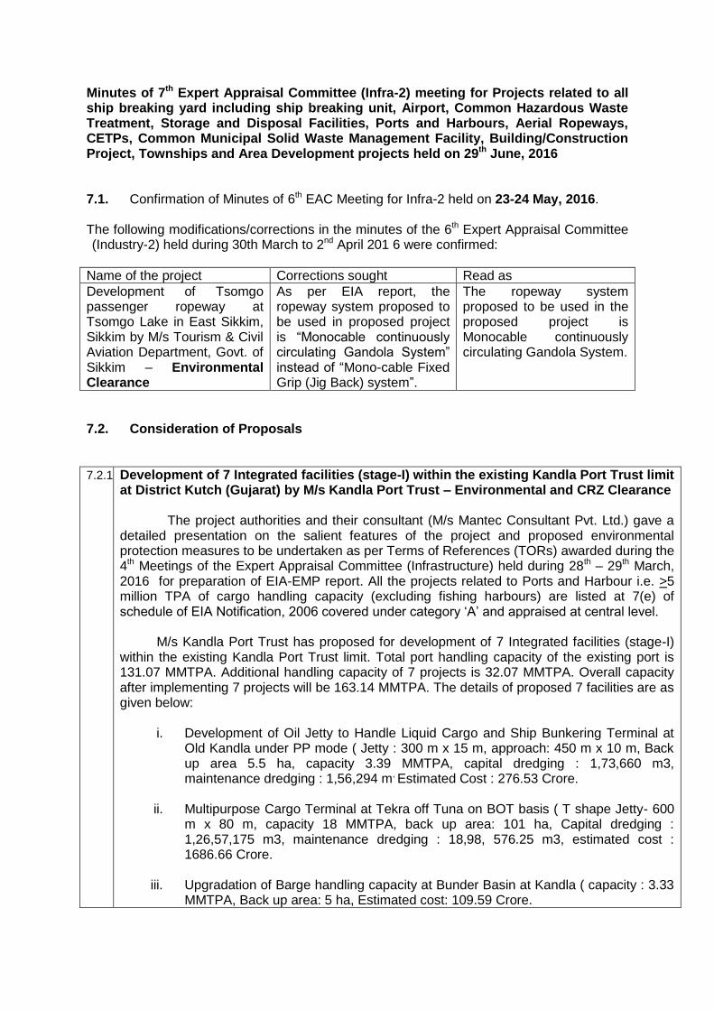
Minutes of 7th Expert Appraisal Committee (Infra-2) meeting for Projects related to all ship breaking yard including ship breaking unit, Airport, Common Hazardous Waste Treatment, Storage and Disposal Facilities, Ports and Harbours, Aerial Ropeways, CETPs, Common Municipal Solid Waste Management Facility, Building/Construction Project, Townships and Area Development projects held on 29th June, 2016 7.1. Confirmation of Minutes of 6th EAC Meeting for Infra-2 held on 23-24 May, 2016. The following modifications/corrections in the minutes of the 6th Expert Appraisal Committee (Industry-2) held during 30th March to 2nd April 201 6 were confirmed:
Name of the project Corrections sought Read as
Development of Tsomgo passenger ropeway at Tsomgo Lake in East Sikkim, Sikkim by M/s Tourism & Civil Aviation Department, Govt. of Sikkim – Environmental Clearance
As per EIA report, the ropeway system proposed to be used in proposed project is “Monocable continuously circulating Gandola System” instead of “Mono-cable Fixed Grip (Jig Back) system”.
The ropeway system proposed to be used in the proposed project is Monocable continuously circulating Gandola System.
7.2. Consideration of Proposals
7.2.1. Development of 7 Integrated facilities (stage-I) within the existing Kandla Port Trust limit at District Kutch (Gujarat) by M/s Kandla Port Trust – Environmental and CRZ Clearance The project authorities and their consultant (M/s Mantec Consultant Pvt. Ltd.) gave a detailed presentation on the salient features of the project and proposed environmental protection measures to be undertaken as per Terms of References (TORs) awarded during the 4th Meetings of the Expert Appraisal Committee (Infrastructure) held during 28th – 29th March, 2016 for preparation of EIA-EMP report. All the projects related to Ports and Harbour i.e. >5 million TPA of cargo handling capacity (excluding fishing harbours) are listed at 7(e) of schedule of EIA Notification, 2006 covered under category ‘A’ and appraised at central level. M/s Kandla Port Trust has proposed for development of 7 Integrated facilities (stage-I) within the existing Kandla Port Trust limit. Total port handling capacity of the existing port is 131.07 MMTPA. Additional handling capacity of 7 projects is 32.07 MMTPA. Overall capacity after implementing 7 projects will be 163.14 MMTPA. The details of proposed 7 facilities are as given below:
i. Development of Oil Jetty to Handle Liquid Cargo and Ship Bunkering Terminal at
Old Kandla under PP mode ( Jetty : 300 m x 15 m, approach: 450 m x 10 m, Back up area 5.5 ha, capacity 3.39 MMTPA, capital dredging : 1,73,660 m3, maintenance dredging : 1,56,294 m, Estimated Cost : 276.53 Crore.
ii. Multipurpose Cargo Terminal at Tekra off Tuna on BOT basis ( T shape Jetty- 600 m x 80 m, capacity 18 MMTPA, back up area: 101 ha, Capital dredging : 1,26,57,175 m3, maintenance dredging : 18,98, 576.25 m3, estimated cost : 1686.66 Crore.
iii. Upgradation of Barge handling capacity at Bunder Basin at Kandla ( capacity : 3.33 MMTPA, Back up area: 5 ha, Estimated cost: 109.59 Crore.
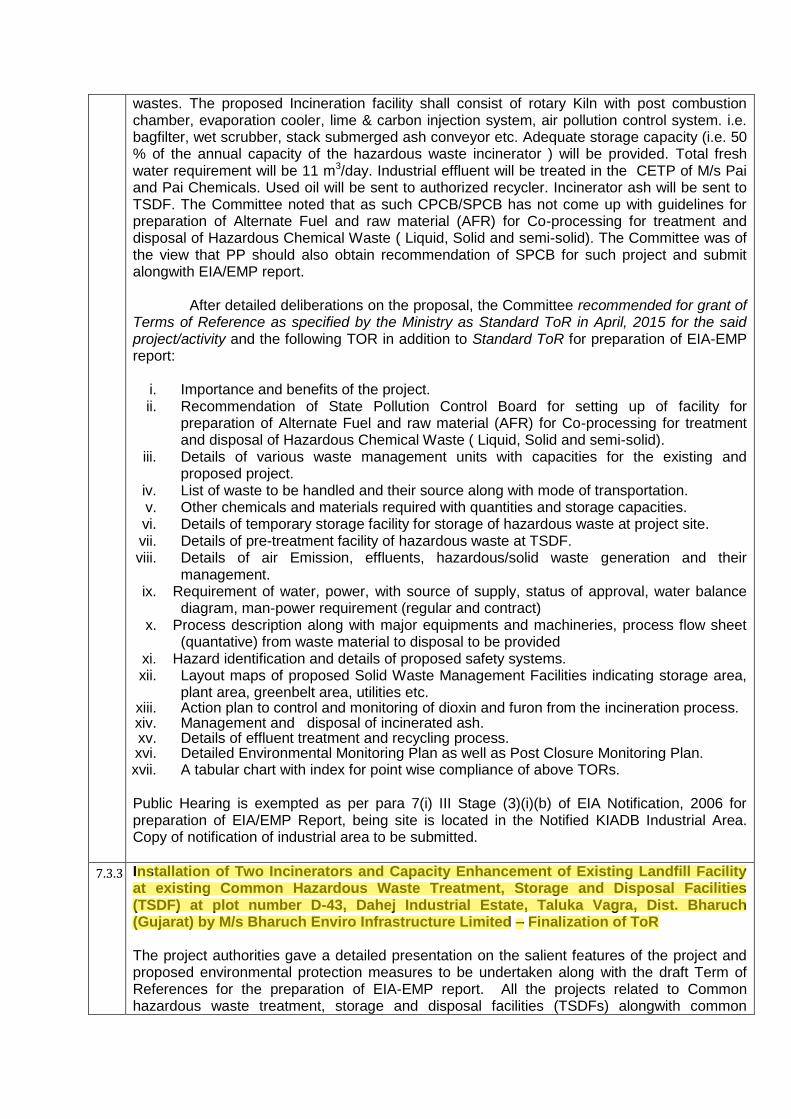
wastes. The proposed Incineration facility shall consist of rotary Kiln with post combustion chamber, evaporation cooler, lime & carbon injection system, air pollution control system. i.e. bagfilter, wet scrubber, stack submerged ash conveyor etc. Adequate storage capacity (i.e. 50 % of the annual capacity of the hazardous waste incinerator ) will be provided. Total fresh water requirement will be 11 m3/day. Industrial effluent will be treated in the CETP of M/s Pai and Pai Chemicals. Used oil will be sent to authorized recycler. Incinerator ash will be sent to TSDF. The Committee noted that as such CPCB/SPCB has not come up with guidelines for preparation of Alternate Fuel and raw material (AFR) for Co-processing for treatment and disposal of Hazardous Chemical Waste ( Liquid, Solid and semi-solid). The Committee was of the view that PP should also obtain recommendation of SPCB for such project and submit alongwith EIA/EMP report.
After detailed deliberations on the proposal, the Committee recommended for grant of Terms of Reference as specified by the Ministry as Standard ToR in April, 2015 for the said project/activity and the following TOR in addition to Standard ToR for preparation of EIA-EMP report:
i. Importance and benefits of the project. ii. Recommendation of State Pollution Control Board for setting up of facility for
preparation of Alternate Fuel and raw material (AFR) for Co-processing for treatment and disposal of Hazardous Chemical Waste ( Liquid, Solid and semi-solid).
iii. Details of various waste management units with capacities for the existing and proposed project.
iv. List of waste to be handled and their source along with mode of transportation. v. Other chemicals and materials required with quantities and storage capacities. vi. Details of temporary storage facility for storage of hazardous waste at project site. vii. Details of pre-treatment facility of hazardous waste at TSDF. viii. Details of air Emission, effluents, hazardous/solid waste generation and their
management. ix. Requirement of water, power, with source of supply, status of approval, water balance
diagram, man-power requirement (regular and contract) x. Process description along with major equipments and machineries, process flow sheet
(quantative) from waste material to disposal to be provided xi. Hazard identification and details of proposed safety systems. xii. Layout maps of proposed Solid Waste Management Facilities indicating storage area,
plant area, greenbelt area, utilities etc. xiii. Action plan to control and monitoring of dioxin and furon from the incineration process. xiv. Management and disposal of incinerated ash. xv. Details of effluent treatment and recycling process. xvi. Detailed Environmental Monitoring Plan as well as Post Closure Monitoring Plan. xvii. A tabular chart with index for point wise compliance of above TORs.
Public Hearing is exempted as per para 7(i) III Stage (3)(i)(b) of EIA Notification, 2006 for preparation of EIA/EMP Report, being site is located in the Notified KIADB Industrial Area. Copy of notification of industrial area to be submitted.
7.3.3 Installation of Two Incinerators and Capacity Enhancement of Existing Landfill Facility at existing Common Hazardous Waste Treatment, Storage and Disposal Facilities (TSDF) at plot number D-43, Dahej Industrial Estate, Taluka Vagra, Dist. Bharuch (Gujarat) by M/s Bharuch Enviro Infrastructure Limited – Finalization of ToR The project authorities gave a detailed presentation on the salient features of the project and proposed environmental protection measures to be undertaken along with the draft Term of References for the preparation of EIA-EMP report. All the projects related to Common hazardous waste treatment, storage and disposal facilities (TSDFs) alongwith common
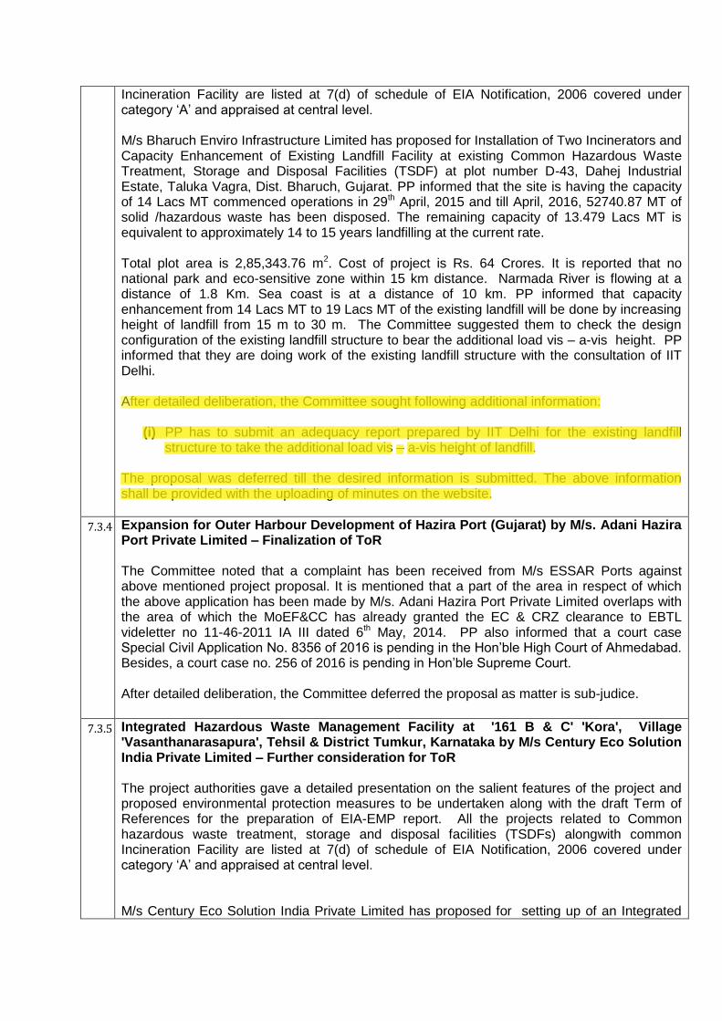
Incineration Facility are listed at 7(d) of schedule of EIA Notification, 2006 covered under category ‘A’ and appraised at central level. M/s Bharuch Enviro Infrastructure Limited has proposed for Installation of Two Incinerators and Capacity Enhancement of Existing Landfill Facility at existing Common Hazardous Waste Treatment, Storage and Disposal Facilities (TSDF) at plot number D-43, Dahej Industrial Estate, Taluka Vagra, Dist. Bharuch, Gujarat. PP informed that the site is having the capacity of 14 Lacs MT commenced operations in 29th April, 2015 and till April, 2016, 52740.87 MT of solid /hazardous waste has been disposed. The remaining capacity of 13.479 Lacs MT is equivalent to approximately 14 to 15 years landfilling at the current rate. Total plot area is 2,85,343.76 m2. Cost of project is Rs. 64 Crores. It is reported that no national park and eco-sensitive zone within 15 km distance. Narmada River is flowing at a distance of 1.8 Km. Sea coast is at a distance of 10 km. PP informed that capacity enhancement from 14 Lacs MT to 19 Lacs MT of the existing landfill will be done by increasing height of landfill from 15 m to 30 m. The Committee suggested them to check the design configuration of the existing landfill structure to bear the additional load vis – a-vis height. PP informed that they are doing work of the existing landfill structure with the consultation of IIT Delhi. After detailed deliberation, the Committee sought following additional information:
(i) PP has to submit an adequacy report prepared by IIT Delhi for the existing landfill structure to take the additional load vis – a-vis height of landfill.
The proposal was deferred till the desired information is submitted. The above information shall be provided with the uploading of minutes on the website.
7.3.4 Expansion for Outer Harbour Development of Hazira Port (Gujarat) by M/s. Adani Hazira Port Private Limited – Finalization of ToR The Committee noted that a complaint has been received from M/s ESSAR Ports against above mentioned project proposal. It is mentioned that a part of the area in respect of which the above application has been made by M/s. Adani Hazira Port Private Limited overlaps with the area of which the MoEF&CC has already granted the EC & CRZ clearance to EBTL videletter no 11-46-2011 IA III dated 6th May, 2014. PP also informed that a court case Special Civil Application No. 8356 of 2016 is pending in the Hon’ble High Court of Ahmedabad. Besides, a court case no. 256 of 2016 is pending in Hon’ble Supreme Court. After detailed deliberation, the Committee deferred the proposal as matter is sub-judice.
7.3.5 Integrated Hazardous Waste Management Facility at '161 B & C' 'Kora', Village
'Vasanthanarasapura', Tehsil & District Tumkur, Karnataka by M/s Century Eco Solution India Private Limited – Further consideration for ToR The project authorities gave a detailed presentation on the salient features of the project and proposed environmental protection measures to be undertaken along with the draft Term of References for the preparation of EIA-EMP report. All the projects related to Common hazardous waste treatment, storage and disposal facilities (TSDFs) alongwith common Incineration Facility are listed at 7(d) of schedule of EIA Notification, 2006 covered under category ‘A’ and appraised at central level. M/s Century Eco Solution India Private Limited has proposed for setting up of an Integrated
REPORT ON
Stability Analysis for
Increasing the Height of Hazardous Waste Landfill
at Dahej (Gujarat)
Prepared for
Bharuch Enviro Infrastructure Limited, Gujarat
Department of Civil Engineering
Indian Institute of Technology Delhi
New Delhi
July 2016
Table of Contents
Sl. No. Title Page No.
1 Background 1
1.1 Objective 1
1.2 Scope 1
1.3 Methodology 1
2 Materials and Properties 2
2.1 Waste 2
2.2 Layers of Cover System 2
3 Analysis 3
3.1 Methods of Analysis 3
3.2 Conditions of Analysis 4
3.3 Minimum Acceptable Factor of Safety 4
4 Results 5
4.1 Permanent Waste Slope 5
4.2 Interface Sliding Stability of Cover System 6
4.3 Temporary Waste Slope 7
4.4 Interface Sliding Stability of Liner System 8
5 Conclusions 11
Acknowledgement 12
Figures 13
1
Stability Analysis for Increasing the Height of Hazardous Waste Landfill
at Dahej (Gujarat)
1 BACKGROUND
Bharuch Enviro Infrastructure Ltd. (BEIL), Gujrat vide their email dated May 30 and 31,
2016 requested IIT Delhi to undertake feasibility study of increasing the height of hazardous
waste landfill at Dahej from 15m to 31.8m. This report presents the details and consequent
findings of the stability analyses performed on waste mass of proposed increased height and
the cover system of landfill.
1.1 Objective
i. Check the stability of waste mass for the proposed height of 31.8m under various field
conditions.
ii. Check the stability of cover system of the landfill at various interfaces.
1.2 Scope
The following scopes of work are covered in this study:
1. Stability analysis of permanent waste slope of inclination 1V:4H, height of waste mass
of 31.8m with 3m wide berms at every 8m height (refer Fig.1).
2. Stability analysis of cover system of landfill at various interfaces between layers of the
cover system.
3. Stability analysis of temporary waste slope of inclination 1V:2H, height of waste mass
of 31.8m with 2m wide berms at every 8m height.
4. Stability analysis of temporary waste slope, of slope inclination 1V:3H, height of waste
mass of 31.8m with 2m wide berms at every 8m height.
1.3 Methodology
Stability analysis for permanent waste slope and temporary waste slope was carried out using
circular slip surface and Morgenstern-Price method. Stability of interface was checked by
sliding wedge method.

2
2 MATERIALS AND PROPERTIES
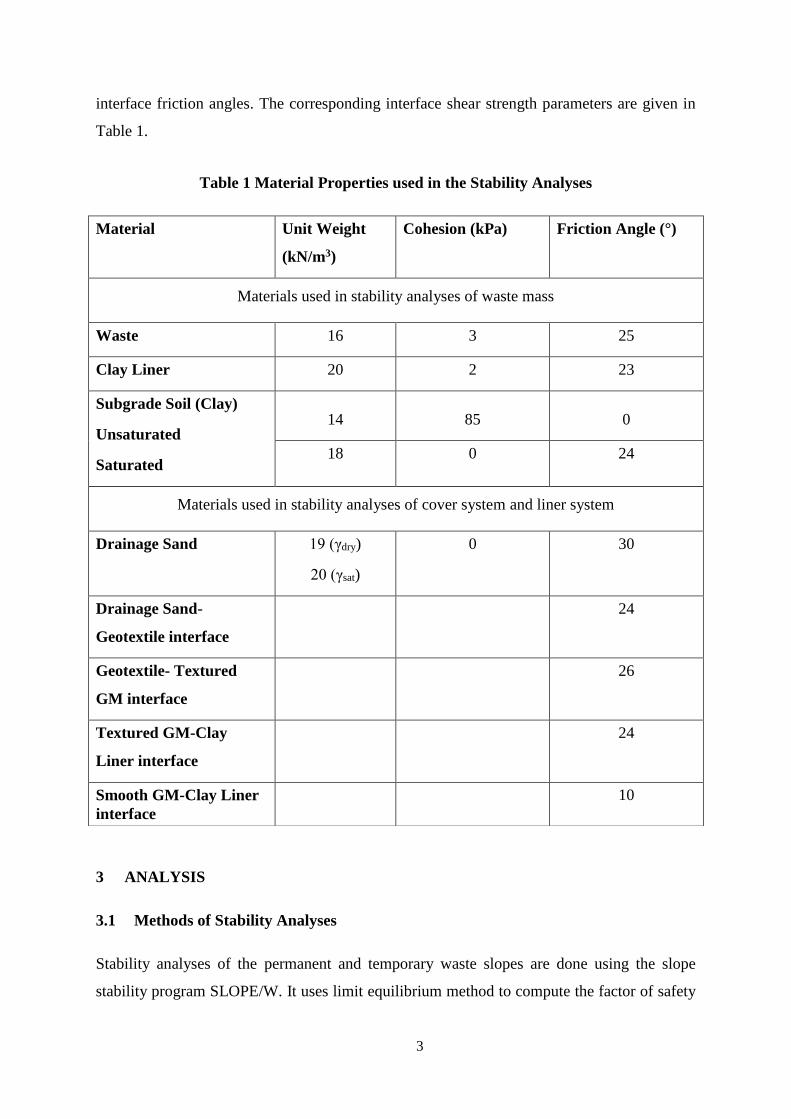
The properties of materials used in the stability analyses are given in Table 1. The material
properties are taken from the soil investigation report and the report submitted by Golder
Associates to BEIL (Report No. 13514290471.502/B.1). These reports were supplied to the
consultant by the client. It is to be noted that the effective strength parameters of subgrade
soil, which is stiff to very stiff highly plastic clay, have been taken from geotechnical
investigation report by M.K. Soil Testing Laboratory using correlations from Gulhati and
Datta (2005).
2.1 Waste
The material properties for the hazardous waste mass have been considered from the report
by Golder Associates to BEIL. As the waste mass is largely composed of inorganic hazardous
waste material, higher unit weight and lower cohesion than municipal solid wastes are
considered (refer Table 1).
2.2 Layers of Cover System
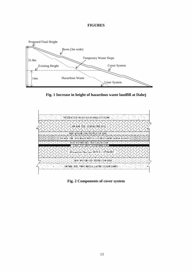
The cover system comprises of the following components sequentially (from the top-down,
see Fig. 2):
Vegetation or rubble masonry + vegetation
600 mm thick compacted soil
250 g/m2 non-woven geotextile
300 mm thick drainage layer, composed of coarse sand and gravel
250 g/m2 non-woven geotextile
1.5 mm thick textured HDPE geomembrane
600 mm thick compacted clay liner of permeability less than 1×10⁻⁹m/s
250 g/m2 non-woven geotextile
300 mm thick gas vent layer, composed of clean medium to coarse sand
For the stability analyses of the cover system, not all the interfaces between the various
components of cover are considered critical. The interfaces between drainage layer and the
underlying non-woven geotextile, the non-woven geotextile and the textured HDPE
geomembrane, and the geomembrane and the clay liner are critical interfaces because of low
3
interface friction angles. The corresponding interface shear strength parameters are given in
Table 1.
Table 1 Material Properties used in the Stability Analyses
3 ANALYSIS
3.1 Methods of Stability Analyses
Stability analyses of the permanent and temporary waste slopes are done using the slope
stability program SLOPE/W. It uses limit equilibrium method to compute the factor of safety
Material Unit Weight
(kN/m3)
Cohesion (kPa) Friction Angle (°)
Materials used in stability analyses of waste mass
Waste 16 3 25
Clay Liner 20 2 23
Subgrade Soil (Clay)
Unsaturated
Saturated
14 85 0
18 0 24
Materials used in stability analyses of cover system and liner system
Drainage Sand 19 (γdry)
20 (γsat)
0 30
Drainage Sand-
Geotextile interface
24
Geotextile- Textured
GM interface
26
Textured GM-Clay
Liner interface
24
Smooth GM-Clay Liner
interface
10
4
against failure. Conventional ‘grid and radius’ method is used to find the failure slip circle
and the corresponding factor of safety. The factor of safety is evaluated by Morgenstern–
Price method, which satisfies both force and moment equilibrium.
Interfacial sliding stability of the cover system is calculated using finite slope analysis/two-
wedge analysis (Koerner and Soong, 1998). This formulation includes an active wedge, a
passive wedge at the toe and a tension crack at the crest of the slope.
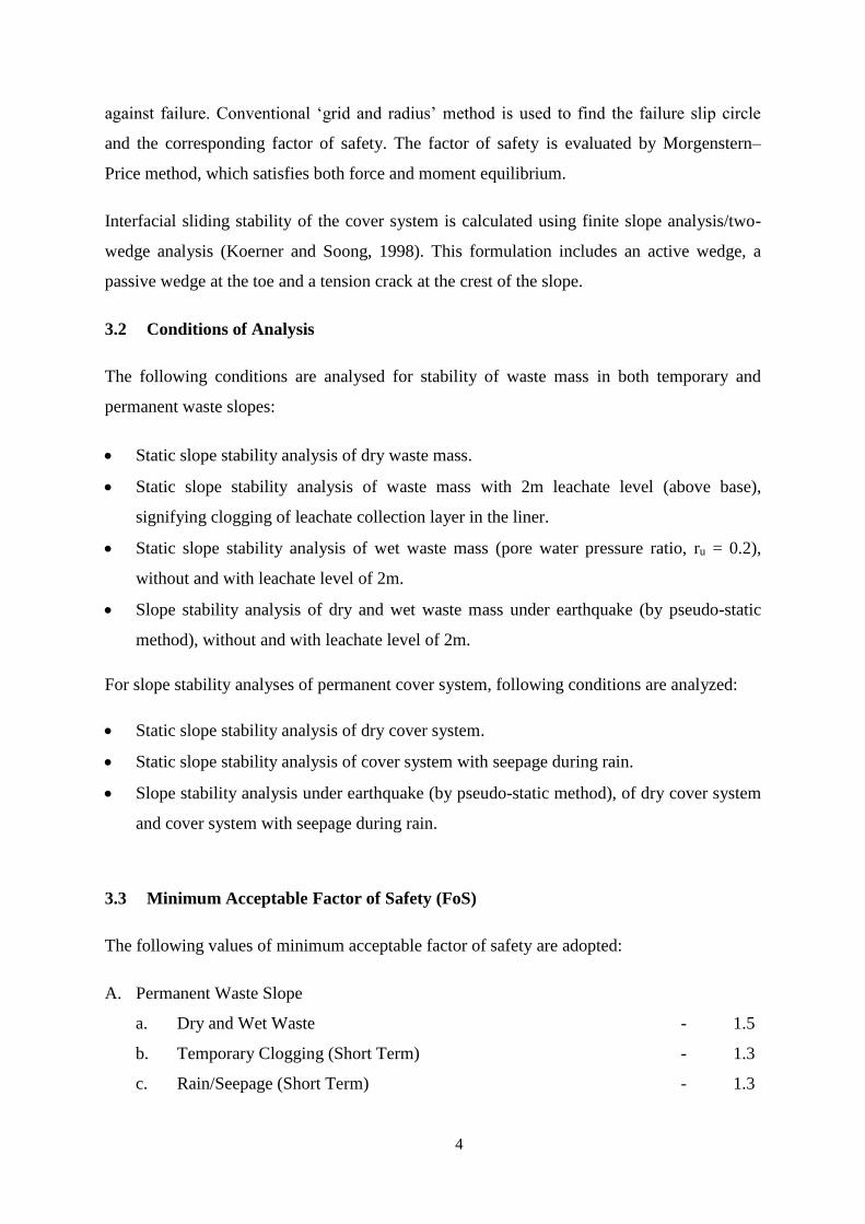
3.2 Conditions of Analysis
The following conditions are analysed for stability of waste mass in both temporary and
permanent waste slopes:
Static slope stability analysis of dry waste mass.
Static slope stability analysis of waste mass with 2m leachate level (above base),
signifying clogging of leachate collection layer in the liner.
Static slope stability analysis of wet waste mass (pore water pressure ratio, ru = 0.2),
without and with leachate level of 2m.
Slope stability analysis of dry and wet waste mass under earthquake (by pseudo-static
method), without and with leachate level of 2m.
For slope stability analyses of permanent cover system, following conditions are analyzed:
Static slope stability analysis of dry cover system.
Static slope stability analysis of cover system with seepage during rain.
Slope stability analysis under earthquake (by pseudo-static method), of dry cover system
and cover system with seepage during rain.
3.3 Minimum Acceptable Factor of Safety (FoS)
The following values of minimum acceptable factor of safety are adopted:
A. Permanent Waste Slope
a. Dry and Wet Waste - 1.5
b. Temporary Clogging (Short Term) - 1.3
c. Rain/Seepage (Short Term) - 1.3
5
d. Earthquake (Pseudo-static) (Very Short Term) - 1.1
e. Rain/Seepage/Clogging + Earthquake (Very Rare) - 1.05
B. Temporary Waste Slope
a. Dry and Wet Waste - 1.3
b. Temporary Clogging (Short Term) - 1.2
c. Rain/Seepage (Short Term) - 1.2
d. Earthquake (Pseudo-static) (Very Short Term) - 1.1
e. Rain/Seepage/Clogging + Earthquake (Very Rare) - 1.05
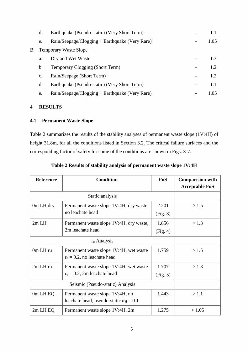
4 RESULTS
4.1 Permanent Waste Slope
Table 2 summarizes the results of the stability analyses of permanent waste slope (1V:4H) of
height 31.8m, for all the conditions listed in Section 3.2. The critical failure surfaces and the
corresponding factor of safety for some of the conditions are shown in Figs. 3-7.
Table 2 Results of stability analysis of permanent waste slope 1V:4H
Reference Condition FoS Comparision with
Acceptable FoS
Static analysis
0m LH dry Permanent waste slope 1V:4H, dry waste,
no leachate head
2.201
(Fig. 3)
> 1.5
2m LH Permanent waste slope 1V:4H, dry waste,
2m leachate head
1.856
(Fig. 4)
> 1.3
ru Analysis
0m LH ru Permanent waste slope 1V:4H, wet waste
ru = 0.2, no leachate head
1.759 > 1.5
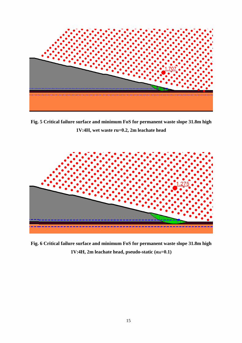
2m LH ru Permanent waste slope 1V:4H, wet waste
ru = 0.2, 2m leachate head
1.707
(Fig. 5)
> 1.3
Seismic (Pseudo-static) Analysis
0m LH EQ Permanent waste slope 1V:4H, no
leachate head, pseudo-static αH = 0.1
1.443 > 1.1
2m LH EQ Permanent waste slope 1V:4H, 2m 1.275 > 1.05
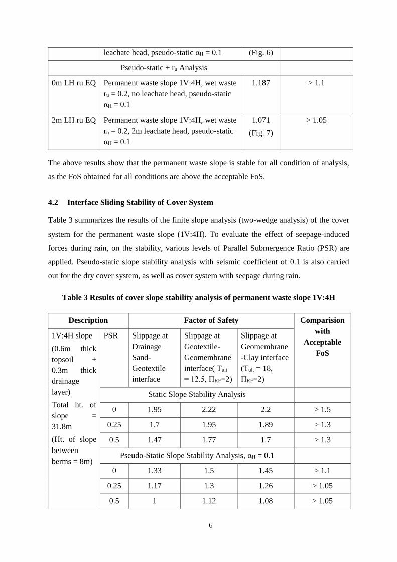
6
leachate head, pseudo-static αH = 0.1 (Fig. 6)
Pseudo-static + ru Analysis
0m LH ru EQ Permanent waste slope 1V:4H, wet waste
ru = 0.2, no leachate head, pseudo-static
αH = 0.1
1.187 > 1.1
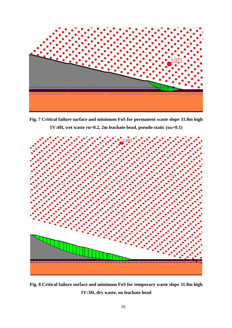
2m LH ru EQ Permanent waste slope 1V:4H, wet waste
ru = 0.2, 2m leachate head, pseudo-static
αH = 0.1
1.071
(Fig. 7)
> 1.05
The above results show that the permanent waste slope is stable for all condition of analysis,
as the FoS obtained for all conditions are above the acceptable FoS.
4.2 Interface Sliding Stability of Cover System
Table 3 summarizes the results of the finite slope analysis (two-wedge analysis) of the cover
system for the permanent waste slope (1V:4H). To evaluate the effect of seepage-induced
forces during rain, on the stability, various levels of Parallel Submergence Ratio (PSR) are
applied. Pseudo-static slope stability analysis with seismic coefficient of 0.1 is also carried
out for the dry cover system, as well as cover system with seepage during rain.
Table 3 Results of cover slope stability analysis of permanent waste slope 1V:4H
Description Factor of Safety Comparision
with
Acceptable
FoS
1V:4H slope
(0.6m thick
topsoil +
0.3m thick
drainage
layer)
Total ht. of
slope =
31.8m
(Ht. of slope
between
berms = 8m)
PSR Slippage at
Drainage
Sand-
Geotextile
interface
Slippage at
Geotextile-
Geomembrane
interface( Tult
= 12.5, ΠRF=2)
Slippage at
Geomembrane
-Clay interface
(Tult = 18,
ΠRF=2)
Static Slope Stability Analysis
0 1.95 2.22 2.2 > 1.5
0.25 1.7 1.95 1.89 > 1.3
0.5 1.47 1.77 1.7 > 1.3
Pseudo-Static Slope Stability Analysis, αH = 0.1
0 1.33 1.5 1.45 > 1.1
0.25 1.17 1.3 1.26 > 1.05
0.5 1 1.12 1.08 > 1.05
7
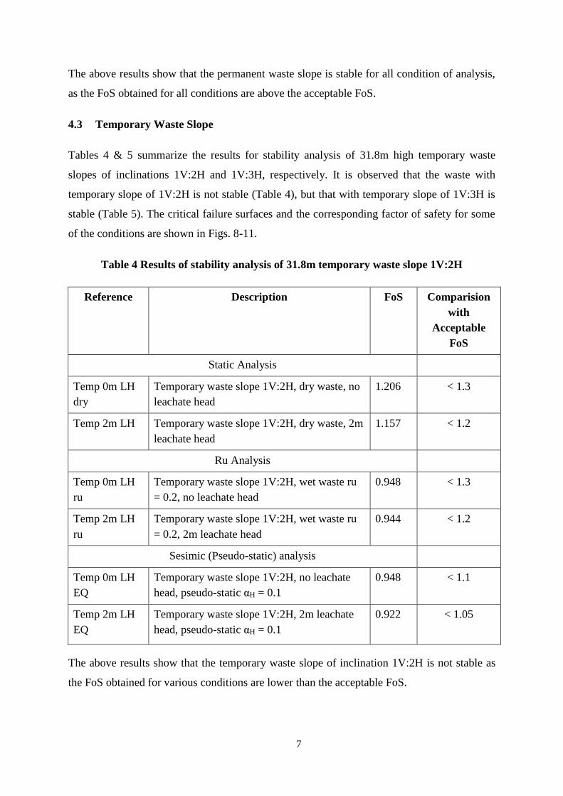
The above results show that the permanent waste slope is stable for all condition of analysis,
as the FoS obtained for all conditions are above the acceptable FoS.
4.3 Temporary Waste Slope
Tables 4 & 5 summarize the results for stability analysis of 31.8m high temporary waste
slopes of inclinations 1V:2H and 1V:3H, respectively. It is observed that the waste with
temporary slope of 1V:2H is not stable (Table 4), but that with temporary slope of 1V:3H is
stable (Table 5). The critical failure surfaces and the corresponding factor of safety for some
of the conditions are shown in Figs. 8-11.
Table 4 Results of stability analysis of 31.8m temporary waste slope 1V:2H
Reference Description FoS Comparision
with
Acceptable
FoS
Static Analysis
Temp 0m LH
dry
Temporary waste slope 1V:2H, dry waste, no
leachate head
1.206 < 1.3
Temp 2m LH Temporary waste slope 1V:2H, dry waste, 2m
leachate head
1.157 < 1.2
Ru Analysis
Temp 0m LH
ru
Temporary waste slope 1V:2H, wet waste ru
= 0.2, no leachate head
0.948 < 1.3
Temp 2m LH
ru
Temporary waste slope 1V:2H, wet waste ru
= 0.2, 2m leachate head
0.944 < 1.2
Sesimic (Pseudo-static) analysis
Temp 0m LH
EQ
Temporary waste slope 1V:2H, no leachate
head, pseudo-static αH = 0.1
0.948 < 1.1
Temp 2m LH
EQ
Temporary waste slope 1V:2H, 2m leachate
head, pseudo-static αH = 0.1
0.922 < 1.05
The above results show that the temporary waste slope of inclination 1V:2H is not stable as
the FoS obtained for various conditions are lower than the acceptable FoS.
8
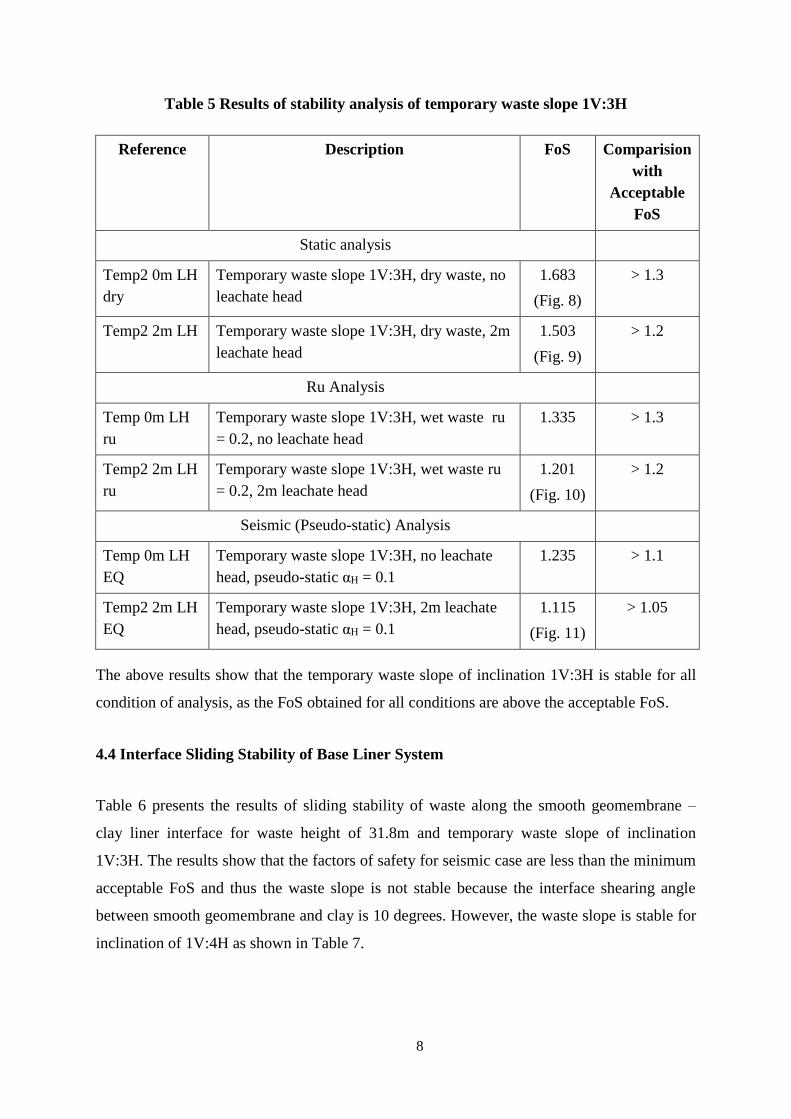
Table 5 Results of stability analysis of temporary waste slope 1V:3H
Reference Description FoS Comparision
with
Acceptable
FoS
Static analysis
Temp2 0m LH
dry
Temporary waste slope 1V:3H, dry waste, no
leachate head
1.683
(Fig. 8)
> 1.3
Temp2 2m LH Temporary waste slope 1V:3H, dry waste, 2m
leachate head
1.503
(Fig. 9)
> 1.2
Ru Analysis
Temp 0m LH
ru
Temporary waste slope 1V:3H, wet waste ru
= 0.2, no leachate head
1.335 > 1.3
Temp2 2m LH
ru
Temporary waste slope 1V:3H, wet waste ru
= 0.2, 2m leachate head
1.201
(Fig. 10)
> 1.2
Seismic (Pseudo-static) Analysis
Temp 0m LH
EQ
Temporary waste slope 1V:3H, no leachate
head, pseudo-static αH = 0.1
1.235 > 1.1
Temp2 2m LH
EQ
Temporary waste slope 1V:3H, 2m leachate
head, pseudo-static αH = 0.1
1.115
(Fig. 11)
> 1.05
The above results show that the temporary waste slope of inclination 1V:3H is stable for all
condition of analysis, as the FoS obtained for all conditions are above the acceptable FoS.
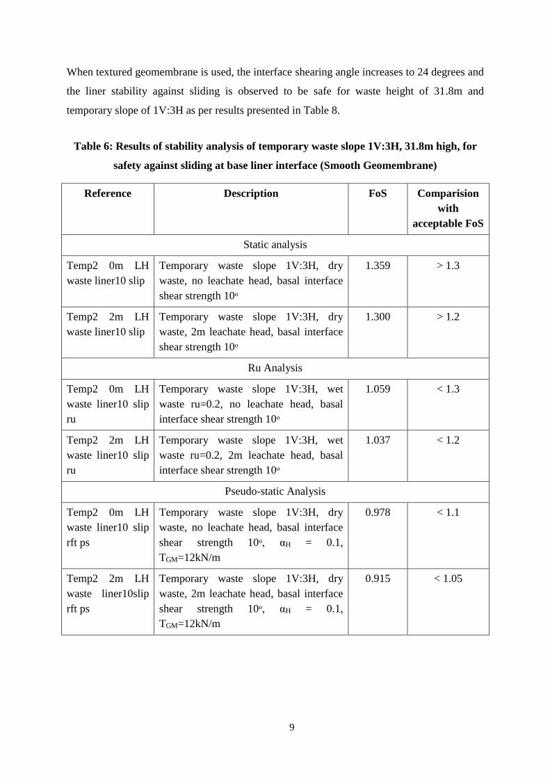
4.4 Interface Sliding Stability of Base Liner System
Table 6 presents the results of sliding stability of waste along the smooth geomembrane –
clay liner interface for waste height of 31.8m and temporary waste slope of inclination
1V:3H. The results show that the factors of safety for seismic case are less than the minimum
acceptable FoS and thus the waste slope is not stable because the interface shearing angle
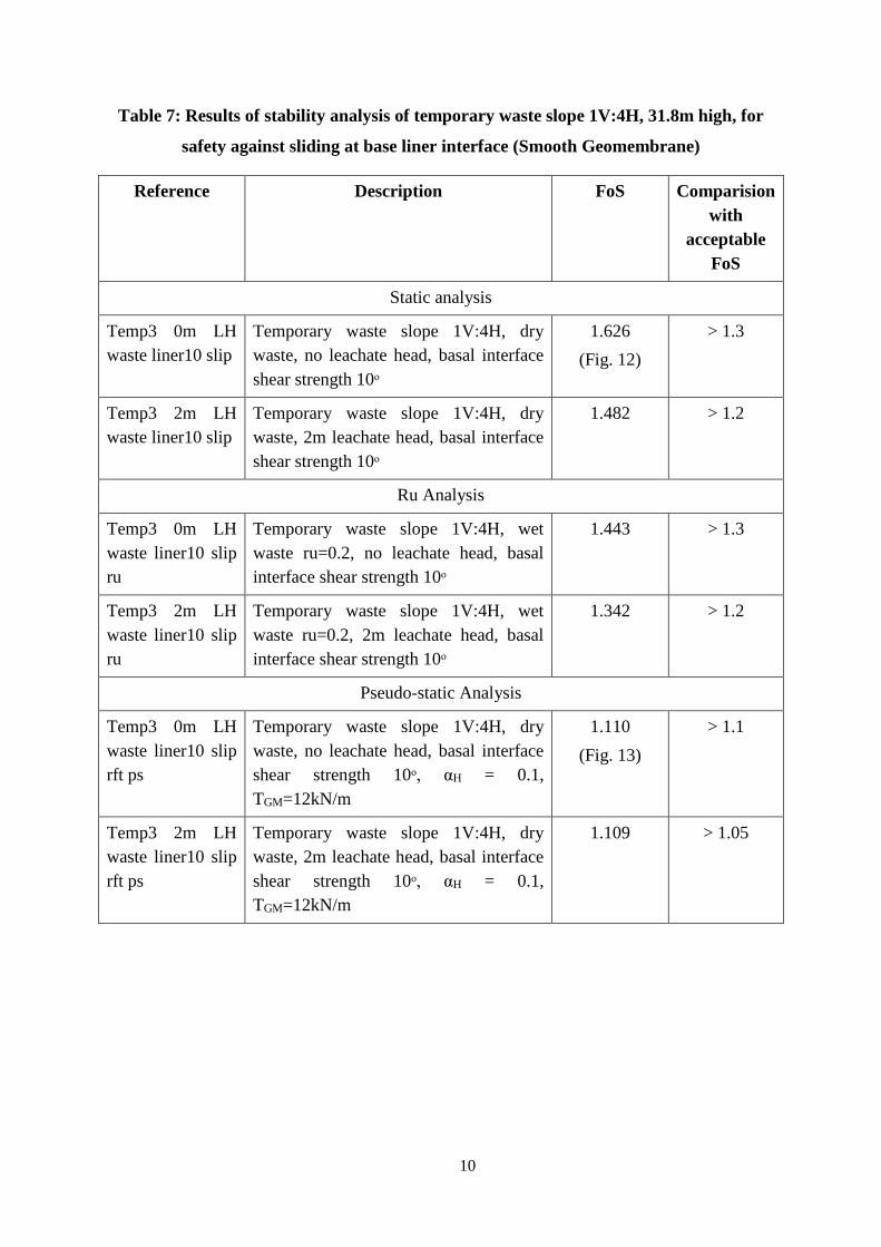
between smooth geomembrane and clay is 10 degrees. However, the waste slope is stable for
inclination of 1V:4H as shown in Table 7.
9
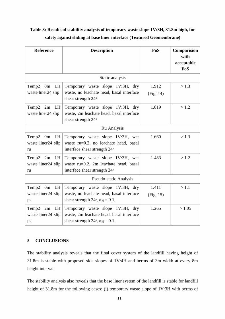
When textured geomembrane is used, the interface shearing angle increases to 24 degrees and
the liner stability against sliding is observed to be safe for waste height of 31.8m and
temporary slope of 1V:3H as per results presented in Table 8.
Table 6: Results of stability analysis of temporary waste slope 1V:3H, 31.8m high, for
safety against sliding at base liner interface (Smooth Geomembrane)
Reference Description FoS Comparision
with
acceptable FoS
Static analysis
Temp2 0m LH
waste liner10 slip
Temporary waste slope 1V:3H, dry
waste, no leachate head, basal interface
shear strength 10ᵒ
1.359 > 1.3
Temp2 2m LH
waste liner10 slip
Temporary waste slope 1V:3H, dry
waste, 2m leachate head, basal interface
shear strength 10ᵒ
1.300 > 1.2
Ru Analysis
Temp2 0m LH
waste liner10 slip
ru
Temporary waste slope 1V:3H, wet
waste ru=0.2, no leachate head, basal
interface shear strength 10ᵒ
1.059 < 1.3
Temp2 2m LH
waste liner10 slip
ru
Temporary waste slope 1V:3H, wet
waste ru=0.2, 2m leachate head, basal
interface shear strength 10ᵒ
1.037 < 1.2
Pseudo-static Analysis
Temp2 0m LH
waste liner10 slip
rft ps
Temporary waste slope 1V:3H, dry
waste, no leachate head, basal interface
shear strength 10ᵒ, αH = 0.1,
TGM=12kN/m
0.978 < 1.1
Temp2 2m LH
waste liner10slip
rft ps
Temporary waste slope 1V:3H, dry
waste, 2m leachate head, basal interface
shear strength 10ᵒ, αH = 0.1,
TGM=12kN/m
0.915 < 1.05
10
Table 7: Results of stability analysis of temporary waste slope 1V:4H, 31.8m high, for
safety against sliding at base liner interface (Smooth Geomembrane)
Reference Description FoS Comparision
with
acceptable
FoS
Static analysis
Temp3 0m LH
waste liner10 slip
Temporary waste slope 1V:4H, dry
waste, no leachate head, basal interface
shear strength 10ᵒ
1.626
(Fig. 12)
> 1.3
Temp3 2m LH
waste liner10 slip
Temporary waste slope 1V:4H, dry
waste, 2m leachate head, basal interface
shear strength 10ᵒ
1.482 > 1.2
Ru Analysis
Temp3 0m LH
waste liner10 slip
ru
Temporary waste slope 1V:4H, wet
waste ru=0.2, no leachate head, basal
interface shear strength 10ᵒ
1.443 > 1.3
Temp3 2m LH
waste liner10 slip
ru
Temporary waste slope 1V:4H, wet
waste ru=0.2, 2m leachate head, basal
interface shear strength 10ᵒ
1.342 > 1.2
Pseudo-static Analysis
Temp3 0m LH
waste liner10 slip
rft ps
Temporary waste slope 1V:4H, dry
waste, no leachate head, basal interface
shear strength 10ᵒ, αH = 0.1,
TGM=12kN/m
1.110
(Fig. 13)
> 1.1
Temp3 2m LH
waste liner10 slip
rft ps
Temporary waste slope 1V:4H, dry
waste, 2m leachate head, basal interface
shear strength 10ᵒ, αH = 0.1,
TGM=12kN/m
1.109 > 1.05
11
Table 8: Results of stability analysis of temporary waste slope 1V:3H, 31.8m high, for
safety against sliding at base liner interface (Textured Geomembrane)
Reference Description FoS Comparision
with
acceptable
FoS
Static analysis
Temp2 0m LH
waste liner24 slip
Temporary waste slope 1V:3H, dry
waste, no leachate head, basal interface
shear strength 24ᵒ
1.912
(Fig. 14)
> 1.3
Temp2 2m LH
waste liner24 slip
Temporary waste slope 1V:3H, dry
waste, 2m leachate head, basal interface
shear strength 24ᵒ
1.819 > 1.2
Ru Analysis
Temp2 0m LH
waste liner24 slip
ru
Temporary waste slope 1V:3H, wet
waste ru=0.2, no leachate head, basal
interface shear strength 24ᵒ
1.660 > 1.3
Temp2 2m LH
waste liner24 slip
ru
Temporary waste slope 1V:3H, wet
waste ru=0.2, 2m leachate head, basal
interface shear strength 24ᵒ
1.483 > 1.2
Pseudo-static Analysis
Temp2 0m LH
waste liner24 slip
ps
Temporary waste slope 1V:3H, dry
waste, no leachate head, basal interface
shear strength 24ᵒ, αH = 0.1,
1.411
(Fig. 15)
> 1.1
Temp2 2m LH
waste liner24 slip
ps
Temporary waste slope 1V:3H, dry
waste, 2m leachate head, basal interface
shear strength 24ᵒ, αH = 0.1,
1.265 > 1.05
5 CONCLUSIONS
The stability analysis reveals that the final cover system of the landfill having height of
31.8m is stable with proposed side slopes of 1V:4H and berms of 3m width at every 8m
height interval.
The stability analysis also reveals that the base liner system of the landfill is stable for landfill
height of 31.8m for the following cases: (i) temporary waste slope of 1V:3H with berms of
12
2m width at every 8m height when textured geomembrane is used and (ii) temporary waste
slope of 1V:4H with berms of 2m width at every 8m height when smooth geomembrane is
used.
Acknowledgement
The work of stability analyses for this study was conducted by Ms. Riya Bhowmik a research
scholar at IIT Delhi. Her contribution is acknowledged.
(Prof. Manoj Datta)
July, 2016
13
FIGURES
Fig. 1 Increase in height of hazardous waste landfill at Dahej
Fig. 2 Components of cover system
Liner System
Hazardous Waste
Cover System
Berm (3m wide)
Existing Height
Proposed Final Height
14m
31.8m Temporary Waste Slope

14
Fig. 3 Critical failure surface and minimum FoS for permanent waste slope 31.8m high
1V:4H, dry waste, no leachate head
Fig. 4 Critical failure surface and minimum FoS for permanent waste slope 31.8m high
1V:4H, dry waste, 2m leachate head
15
Fig. 5 Critical failure surface and minimum FoS for permanent waste slope 31.8m high
1V:4H, wet waste ru=0.2, 2m leachate head
Fig. 6 Critical failure surface and minimum FoS for permanent waste slope 31.8m high
1V:4H, 2m leachate head, pseudo-static (αH=0.1)
16
Fig. 7 Critical failure surface and minimum FoS for permanent waste slope 31.8m high
1V:4H, wet waste ru=0.2, 2m leachate head, pseudo-static (αH=0.1)
Fig. 8 Critical failure surface and minimum FoS for temporary waste slope 31.8m high
1V:3H, dry waste, no leachate head
17
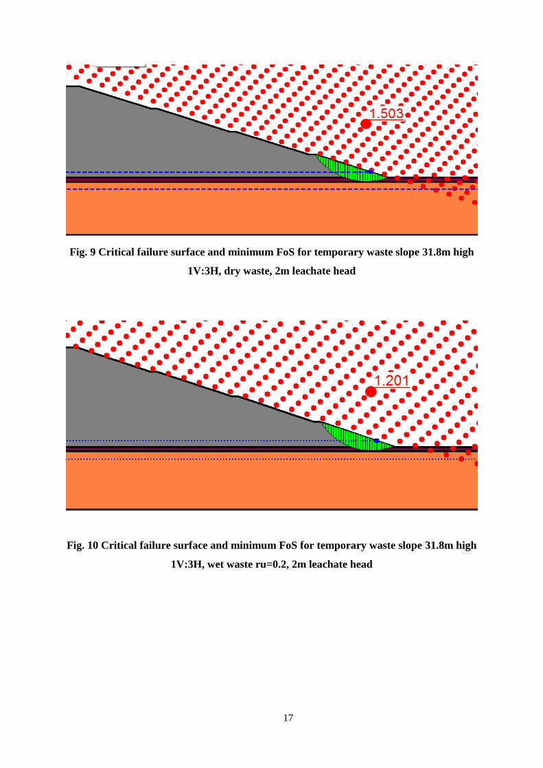
Fig. 9 Critical failure surface and minimum FoS for temporary waste slope 31.8m high
1V:3H, dry waste, 2m leachate head
Fig. 10 Critical failure surface and minimum FoS for temporary waste slope 31.8m high
1V:3H, wet waste ru=0.2, 2m leachate head
18
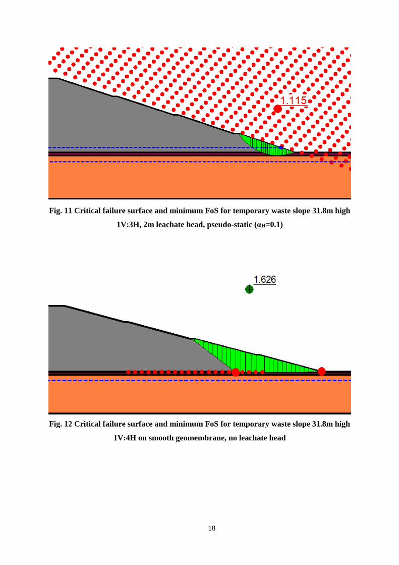
Fig. 11 Critical failure surface and minimum FoS for temporary waste slope 31.8m high
1V:3H, 2m leachate head, pseudo-static (αH=0.1)
Fig. 12 Critical failure surface and minimum FoS for temporary waste slope 31.8m high
1V:4H on smooth geomembrane, no leachate head

19
Fig. 13 Critical failure surface and minimum FoS for temporary waste slope 31.8m high
1V:4H on smooth geomembrane, no leachate head, pseudo-static (αH=0.1)
Fig. 14 Critical failure surface and minimum FoS for temporary waste slope 31.8m high
1V:3H on textured geomembrane, no leachate head
20
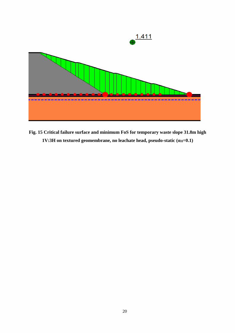
Fig. 15 Critical failure surface and minimum FoS for temporary waste slope 31.8m high
1V:3H on textured geomembrane, no leachate head, pseudo-static (αH=0.1)