minto mine underground mine development and operations ... · 7.4 compressed air ... 8.4 industrial...
TRANSCRIPT
Minto Mine QML-0001
Underground Mine Development and Operations Plan
June 2014
Prepared by:
Minto Explorations Ltd.
Minto Mine QML-0001 Underground Mine Development and Operations Plan
Table of Contents 1 Background .........................................................................................................................................................1 2 Current Operations.............................................................................................................................................2
2.1 Area 118, Area 2 Underground Development via Minto South Portal ......................................................2 2.2 M-Zone Underground .................................................................................................................................2
3 Deposits and Ore Reserves .................................................................................................................................7 3.1 Ore Reserves ...............................................................................................................................................9 3.2 Scheduling ..................................................................................................................................................9
4 Mine Development and Design ....................................................................................................................... 10 4.1 Minto South Underground ...................................................................................................................... 10 4.2 M-Zone .................................................................................................................................................... 11
4.2.1 M-Zone Ore ..................................................................................................................................... 11 5 Mine Operation ............................................................................................................................................... 14
5.1 Minto South / Wildfire Underground Material Handling ........................................................................ 14 5.2 M- Zone Material Handling ..................................................................................................................... 14
6 Underground Geotechnical Assessment ......................................................................................................... 15 6.1 Hydrogeological Assessment ................................................................................................................... 15 6.2 Area 118, Area 2, Minto East, Copper Keel and Wild Fire Underground ................................................ 16
6.2.1 Mining Method – Geotechnical Considerations .............................................................................. 16 6.2.2 Orebody Geometry .......................................................................................................................... 16 6.2.3 Rock Mass Assessment .................................................................................................................... 16 6.2.4 Underground Excavation Design ..................................................................................................... 17 6.2.5 Pillar Design and Stability Assessment ............................................................................................ 19
6.3 Fill ............................................................................................................................................................ 19 6.3.1 Longhole Stoping Opportunities ...................................................................................................... 20 6.3.2 Kinematic Wedge Analysis ............................................................................................................... 23 6.3.3 Lateral Development ....................................................................................................................... 23 6.3.4 Vertical Development ...................................................................................................................... 23 6.3.5 Ground Support Requirements ....................................................................................................... 24
6.4 Area 2 (M-Zone) Underground Geotechnical Parameters ...................................................................... 24 6.4.1 Geologic Assessment of the M-Zone Portal .................................................................................... 25 6.4.2 M-Zone Ground Support for the Portal Collar ................................................................................. 27 6.4.3 General M-Zone Surface Work Area Rockfall Protection Plan ........................................................ 30 6.4.4 M-Zone Underground Development Support ................................................................................. 31 6.4.5 M-Zone Stope Stability .................................................................................................................... 31 6.4.6 Pillar Stability ................................................................................................................................... 34
7 Ventilation, Ancillary Infrastructure, and Dewatering, ................................................................................... 38 7.1 Mine Ventilation ...................................................................................................................................... 38
7.1.1 Minto South Portal Ventilation – Stage 1 ........................................................................................ 38 7.1.2 Commissioning of 118 RA raise to surface and development of Minto East OB access drift – Stage 2 40 7.1.3 Minto East OB Full Production - Stage 3 ........................................................................................ 41 7.1.4 Minto East OB production and Development of Copper Keel access drift – Stage 4 ...................... 42 7.1.5 Copper Keel OB Full Production – Stage 5 ....................................................................................... 43 7.1.6 M- Zone Ventilation ......................................................................................................................... 43
7.2 Mine Air Heating ...................................................................................................................................... 45
i
Minto Mine QML-0001 Underground Mine Development and Operations Plan
7.2.1 Minto South Portal Air Heating ....................................................................................................... 45 7.2.2 M- Zone Portal Air Heating .............................................................................................................. 45
7.3 Underground Electrical Power ................................................................................................................ 45 7.3.1 Minto South portal Electrical Power ............................................................................................... 46 7.3.2 M- Zone Electrical Power ................................................................................................................. 46
7.4 Compressed Air ....................................................................................................................................... 46 7.5 Dewatering and Effluent Treatment ....................................................................................................... 47
7.5.1 Water Supply ................................................................................................................................... 47 7.5.2 Minto South Portal Dewatering ....................................................................................................... 47 7.5.3 M- Zone Water Management .......................................................................................................... 49 7.5.4 Mine Water Quality and Inflow Monitoring .................................................................................... 50
7.6 Communications ...................................................................................................................................... 50 7.7 Explosive Storage and Handling .............................................................................................................. 50 7.8 Fuel Storage and Distribution .................................................................................................................. 50
8 Mine safety ...................................................................................................................................................... 51 8.1 General Mine Safety ................................................................................................................................ 51 8.2 Emergency Response ............................................................................................................................... 51 8.3 Hours of Work ......................................................................................................................................... 52 8.4 Industrial Hygiene and Fatigue Management Programs ......................................................................... 52 8.5 Hours of Underground Exposure Monitoring .......................................................................................... 53 8.6 First Line Supervisory Training................................................................................................................. 53
8.6.1 Diesel Equipment ............................................................................................................................. 53 8.6.2 Portable Compressors ..................................................................................................................... 53 8.6.3 Shotcrete ......................................................................................................................................... 53
8.7 WCHSB Reporting .................................................................................................................................... 53 9 Conclusion ....................................................................................................................................................... 55
List of Figures
Figure 2-1: Site overview. ...........................................................................................................................................3 Figure 2-2: Schematic of Minto South Portal surface infrastructure. ........................................................................4 Figure 2-3: Minto South Underground development as of January 2014. ................................................................5 Figure 2-4: General arrangement of M-Zone surface infrastructure. ........................................................................6 Figure 3-1: Plan view of underground development and ore zones. .........................................................................8 Figure 3-2: Underground ore release by month. .................................................................................................... 10 Figure 3-3: Gantt chart of ore zones mined. ........................................................................................................... 10 Figure 4-1: Typical decline cross-section. ................................................................................................................ 11 Figure 4-2: Plan view of M-zone ore lens. ............................................................................................................... 12 Figure 4-3: Perspective View of M-zone Ore in Relation to Pit Design ................................................................... 12 Figure 4-4: M-zone Development Overview ........................................................................................................... 13 Figure 6-1: Ouchi Critical Span Curve ...................................................................................................................... 18 Figure 6-2: Q-system unsupported span limits for permanent openings (ESR=1.6). .............................................. 18 Figure 6-3: Potvin stope stability graph—Area 118 and Minto East zones. ............................................................ 21 Figure 6-4: Mawdsley stope probability-of-failure graph—Area 118 zone............................................................. 22
ii
Minto Mine QML-0001 Underground Mine Development and Operations Plan
Figure 6-5: Geologic assessment from December 23, 2013. ................................................................................... 25 Figure 6-6: Detailed / up-close geologic mapping of M-Zone portal, 691-697 m (Jan 5, 2014). ............................ 26 Figure 6-7: Detailed, Up-close, Geologic Mapping of Area Immediately to Right of M-Zone portal, (Jan 5, 2014) 26 Figure 6-8: Area 2 pit joint sets (SRK 2013). ............................................................................................................ 27 Figure 6-9:M-Zone Portal collar bolting layout ....................................................................................................... 28 Figure 6-10: Type 1 ground support standard ......................................................................................................... 29 Figure 6-11: Cross section of rockfall protection measures .................................................................................... 30 Figure 6-12: Stope stability for average conditions................................................................................................. 33 Figure 6-13: FLAC 3D model mesh .......................................................................................................................... 34 Figure 6-14: FLAC 3D model mesh of stopes ........................................................................................................... 35 Figure 7-1: Minto South Portal ventilation. ............................................................................................................. 38 Figure 7-2: Minto South Portal ventilation - Stage 2 ............................................................................................... 40 Figure 7-3: Minto South Portal ventilation - Stage 3 ............................................................................................... 41 Figure 7-4: Minto South Portal ventilation - Stage 4 ............................................................................................... 42 Figure 7-5: Minto South Portal ventilation - Stage 5 ............................................................................................... 43 Figure 7-6: Ventilation system general arrangement. ............................................................................................ 44 Figure 7-7: Minto South Portal dewatering (current) ............................................................................................. 48 Figure 7-8: M-Zone dewatering general arrangement. ........................................................................................... 49 Figure 9-1: Right wall of I-Drift showing J6 joint set ................................................................................................ 58 Figure 9-2: Footwall contact in I-Drift right wall ..................................................................................................... 59 Figure 9-3: Close up of footwall contact in I-Drift right wall ................................................................................... 59 Figure 9-4: Left wall of I-Drift .................................................................................................................................. 60 Figure 9-5: Diamond Drillhole 06SWC108 ............................................................................................................... 61 Figure 9-6: 06SWC108 showing the depth of the I-Drift (157.58-163.68m) ........................................................... 61 Figure 9-7: 06SWC108 showing the depth of the I-Drift (157.58-163.68m) ........................................................... 62 Figure 9-8: Stability Graph for Minimum Stope Size ............................................................................................... 67 Figure 9-9: Stability Graph for Average Stope Size .................................................................................................. 68 Figure 9-10: Stability Graph for Maximum Stope Size ............................................................................................ 69 Figure 9-11: Maximum possible sidewall wedge - looking northeast into stope .................................................... 70 Figure 9-12: Maximum possible sidewall wedge - looking west at stope wall ....................................................... 70 Figure 9-13: Maximum possible back wedge - looking northeast into stope ......................................................... 71 Figure 9-14: Maximum possible back wedge - looking east .................................................................................... 71
List of Tables
Table 3-1: Nomenclature for underground complexes, portals, and zones at Minto................................................7 Table 3-2: Reserves (including Phase IV Minto South Underground Reserves). ........................................................9 Table 6-1: Pillar Calculations ................................................................................................................................... 19 Table 6-2: Area 118 minimum support requirements............................................................................................. 24 Table 6-3: M-Zone minimum support requirements .............................................................................................. 31 Table 6-4: Overbreak estimates .............................................................................................................................. 31
iii
Minto Mine QML-0001 Underground Mine Development and Operations Plan
Table 6-5: Rock properties used in the modeling .................................................................................................... 35 Table 7-1: Ventilation requirements Minto South Portal ....................................................................................... 39 Table 7-2: M-Zone Equipment Usage Underground ............................................................................................... 44 Table 7-3: Average temperature by month and propane consumption (Minto South Portal). .............................. 45 Table 7-4: Average temperature by month and propane consumption (M-Zone) ................................................. 45 Table 9-1: M-Zone Ore Rock Quality ....................................................................................................................... 57 Table 9-2: M-Zone Ore Rock Structure .................................................................................................................... 57 Table 9-3: Comparison of Modelled vs Mapped Ore Properties............................................................................. 62 Table 9-4: Comparison of Modelled vs Mapped Ore Properties............................................................................. 63 Table 9-5: Stope Geometry ..................................................................................................................................... 65 Table 9-6: Stope Stability Results ............................................................................................................................ 65 Table 9-7: Summary of Kinematic Analysis ............................................................................................................. 72
List of Appendices
Appendix A – M-Zone Updated Geotechnical Assessment Appendix B – Safe Work Procedure Blast Clearing M-Zone Appendix C – Minto Mine Emergency Response Plan – March 2014 Appendix D – Hours of Work Variance Request and Approval Appendix E – Fatigue Management Plan
iv
Minto Mine QML-0001 Underground Mine Development and Operations Plan – June 2014
1 Background This Underground Mine Development and Operations Plan (UMDOP) has been prepared to satisfy the requirements of Quartz Mining Licence (QML-0001) for the development and mining of the underground at Minto Mine, owned by Minto Explorations Ltd.
Minto Mine has been in operation since 2007. Operations were focused solely on open pit mining from 2007 until 2012 at which time underground mine development commenced. Underground development continued through early 2013 at the Minto South portal.
In January 2014, through continued consultation with Yukon Government Department of Energy, Mines and Resources, Minto sought approval for changing the mining sequence such that the “M-zone,” originally the final ore zone to be mined in the Phase IV plan, could be brought ahead in the schedule and accessed from the bottom of the completed Area 2 Stage 2 pit. Approval to proceed was granted on January 10, 2014.
This revision to the UMDOP compiles information previously submitted and approved for the Phase IV underground and the M-zone scheduling change approval, and adds the Phase V/VI activities proposed in YESAB application 2013-0100.
In August 2013, Energy, Mines and Resources published a guidance document for quartz mining projects that details the requirements for a Mine Development and Operations Plan under the QML. Some of those requirements are largely related to the surface mine operations and have been addressed in various other QML-0001 submissions, primarily the "Mine Development and Operations Plan.”
1
Minto Mine QML-0001 Underground Mine Development and Operations Plan – June 2014
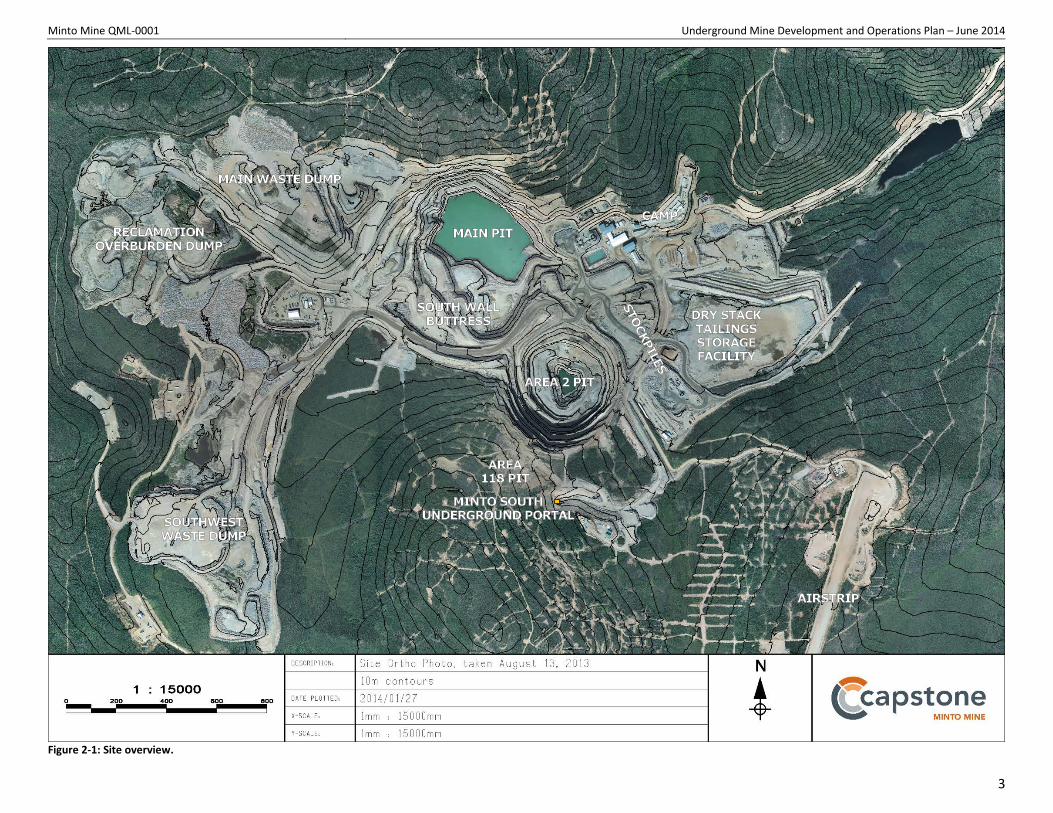
2 Current Operations Figure 2-1 shows an aerial overview of the mine site as of August 2013. The site configuration has not significantly changed since the photo was taken; open pit mining continued in the Area 2 pit until completion in January 2014, and mining commenced in the Area 118 pit in January and is expected to continue to July 2014 at a reduced rate. Waste rock from mining operations is currently being deposited in the Southwest Dump and the South Wall Buttress; the Mill Valley Fill Extension was completed in early 2013. Overburden was deposited in the Reclamation Overburden Dump, or in the Ice-Rich Overburden dump, depending on the ice content of the material; however, no overburden remains to be mined as part of the Phase IV mine plan.
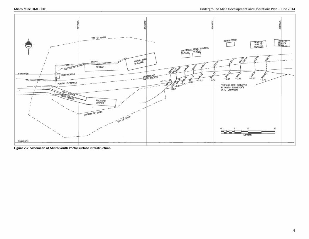
2.1 Area 118, Area 2 Underground Development via Minto South Portal Underground development commenced at the Minto South Portal in mid-2012 with clearing of the overburden at the portal location and construction of an access road. The first blast occurred at the portal in September, and the portal was collared to 15 m with a steel portal access structure. Figure 2-2 shows the general surface layout at the Minto South Portal.
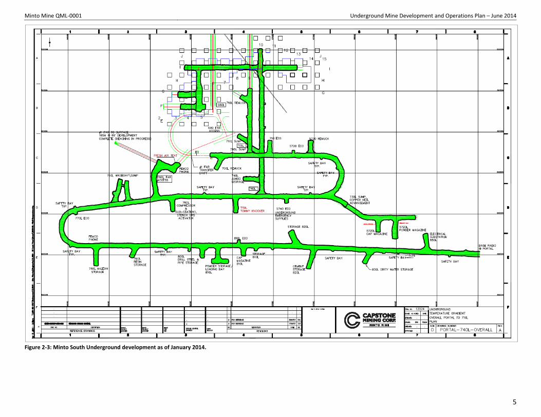
Development of the Minto South Underground continued in 2014: Figure 2-3 illustrates the current extent of the underground development. A fresh air raise, in addition serving as a secondary egress, was completed in January 2014.
2.2 M-Zone Underground As part of the ongoing optimization of mining plans, Minto identified an opportunity to extract a portion of the Phase IV underground reserve, accessible from the bottom of the Area 2 pit, earlier in the mining sequence. This specific area was previously a stope within the Area 2 portion of the Phase IV Minto South Underground, where it was scheduled to be one of the last mined. It was given the name “M-zone” to distinguish it from other parts of the Phase IV underground plan.
In order to expedite the access to high-grade ore and avoid the risk of mining in close proximity to the tailings and water deposit slated for Area 2, it was determined that a portal could be collared at the bottom of the pit, along the west wall, directly into the ore. After a short development campaign along the footwall of the ore zone, 250,000 tonnes of ore at 1.81% grade can be extracted using an up-hole retreat mining method.
As per the approval detailed in Section 1, M-zone surface construction and development commenced in January 2014. As of early June 2014, M-zone development is complete, a secondary egress raise is broken through to surface, and longhole production drilling is ongoing.
2
Minto Mine QML-0001 Underground Mine Development and Operations Plan – June 2014
Figure 2-1: Site overview.
3
Minto Mine QML-0001 Underground Mine Development and Operations Plan – June 2014
Figure 2-2: Schematic of Minto South Portal surface infrastructure.
4
Minto Mine QML-0001 Underground Mine Development and Operations Plan – June 2014
Figure 2-3: Minto South Underground development as of January 2014.
5
Minto Mine QML-0001 Underground Mine Development and Operations Plan – June 2014
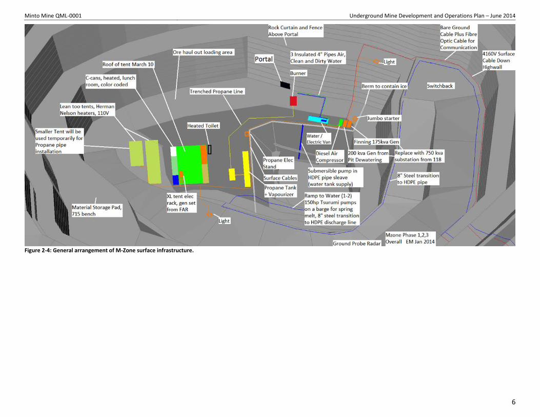
Figure 2-4: General arrangement of M-Zone surface infrastructure.
6
Minto Mine QML-0001 Underground Mine Development and Operations Plan – June 2014
3 Deposits and Ore Reserves The underground mining assessed as part of Phase IV consists of several stopes in the Area 2 and Area 118 zones, accessed via the Minto South Portal.
Phase V/VI adds several ore zones to the mine plan:
• To the existing Minto South Underground complex, accessed from the Minto South Portal, Phase IV will add the Minto East and Copper Keel zones, as well as some deeper stopes in the Wildfire zone.
• A separate underground complex, known as the Wildfire Underground, will access the upper stopes of the Wildfire zone.
The following table summarizes the nomenclature associated with Minto’s ore zones and lists the phase of permitting under which each has been assessed.
Underground Complex Access Zones Permitting Minto South Underground Minto South Portal Area 118 Phase IV
Area 2 Phase IV Minto East Phase V/VI Copper Keel Phase V/VI Wildfire Phase V/VI
M-zone M-zone Portal M-zone Phase IV Wildfire Underground Wildfire Portal Wildfire Phase V/VI
Table 3-1: Nomenclature for underground complexes, portals, and zones at Minto.
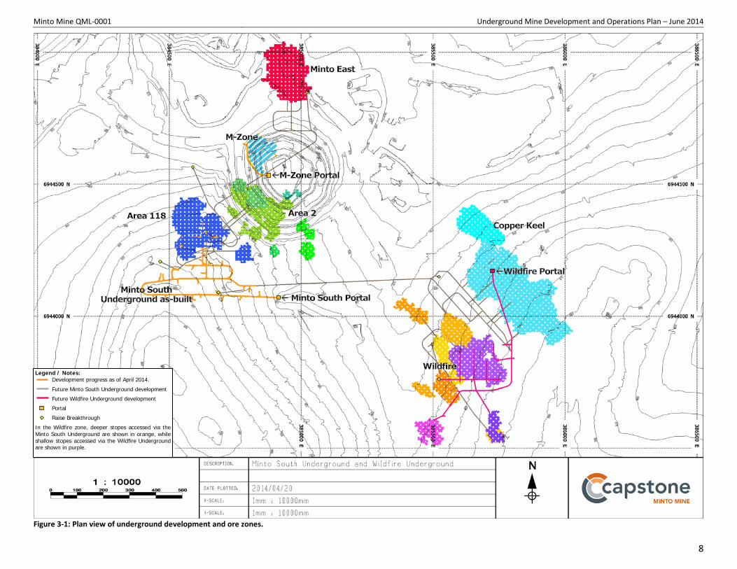
Figure 3-1 shows all of the aforementioned ore zones and the development required to access them.
The MSU (Minto South Underground) describes development underneath and around the Area 2 and Area 118 pits, accessed from the Minto South Portal, which is southwest of the Area 2 Pit. This underground development was presented in the Phase IV application to YESAB and approved in subsequent major license amendments.
The Wildfire Underground accesses relatively shallow ore zones from a separate portal that will have its own dedicated infrastructure. It will be mined after the completion of the MSU; underground mining activity will transition to the Wildfire Underground as the other zones near completion.
7
Minto Mine QML-0001 Underground Mine Development and Operations Plan – June 2014
Figure 3-1: Plan view of underground development and ore zones.
Legend / Notes: Development progress as of April 2014.
Future Minto South Underground development
Future Wildfire Underground development
Portal
Raise Breakthrough
In the Wildfire zone, deeper stopes accessed via the Minto South Underground are shown in orange, while shallow stopes accessed via the Wildfire Underground are shown in purple.
8
Minto Mine QML-0001 Underground Mine Development and Operations Plan – June 2014
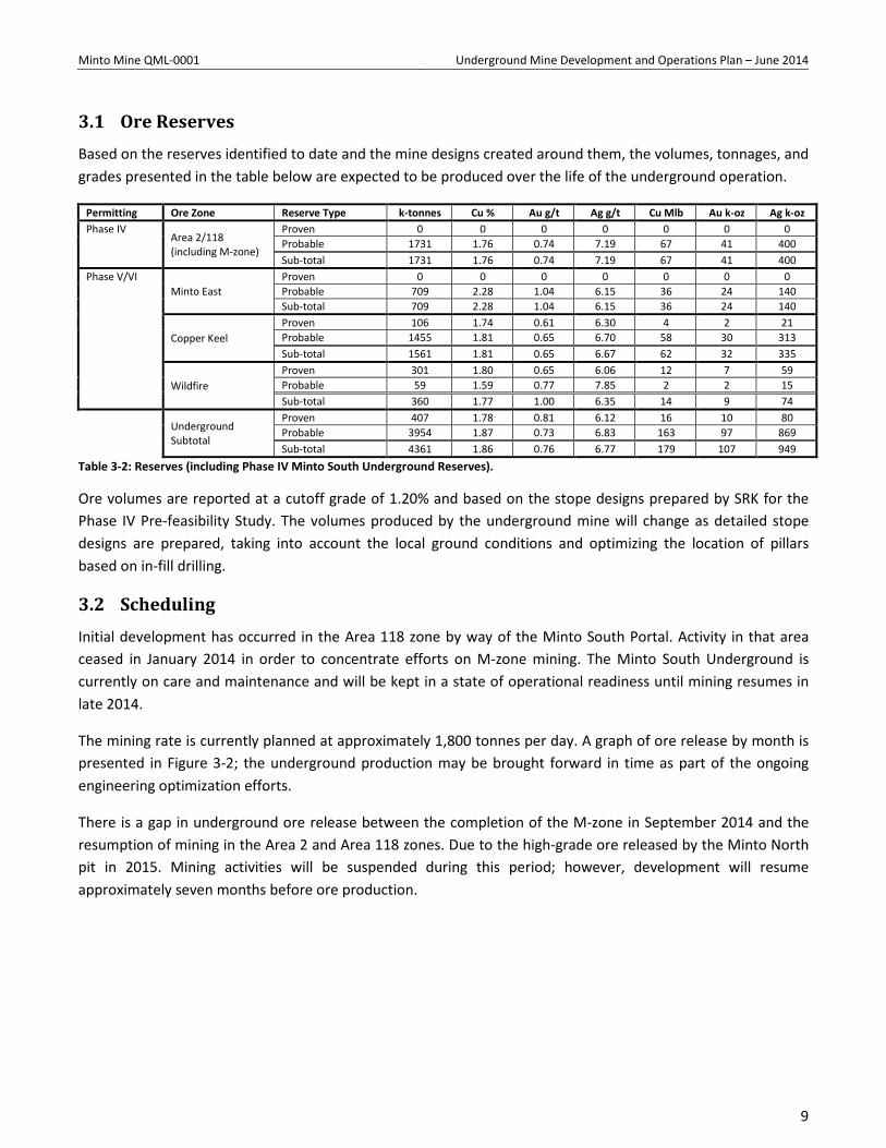
3.1 Ore Reserves Based on the reserves identified to date and the mine designs created around them, the volumes, tonnages, and grades presented in the table below are expected to be produced over the life of the underground operation.
Permitting Ore Zone Reserve Type k-tonnes Cu % Au g/t Ag g/t Cu Mlb Au k-oz Ag k-oz Phase IV
Area 2/118 (including M-zone)
Proven 0 0 0 0 0 0 0 Probable 1731 1.76 0.74 7.19 67 41 400 Sub-total 1731 1.76 0.74 7.19 67 41 400
Phase V/VI Minto East
Proven 0 0 0 0 0 0 0 Probable 709 2.28 1.04 6.15 36 24 140 Sub-total 709 2.28 1.04 6.15 36 24 140
Copper Keel Proven 106 1.74 0.61 6.30 4 2 21 Probable 1455 1.81 0.65 6.70 58 30 313 Sub-total 1561 1.81 0.65 6.67 62 32 335
Wildfire Proven 301 1.80 0.65 6.06 12 7 59 Probable 59 1.59 0.77 7.85 2 2 15 Sub-total 360 1.77 1.00 6.35 14 9 74
Underground Subtotal
Proven 407 1.78 0.81 6.12 16 10 80 Probable 3954 1.87 0.73 6.83 163 97 869 Sub-total 4361 1.86 0.76 6.77 179 107 949
Table 3-2: Reserves (including Phase IV Minto South Underground Reserves).
Ore volumes are reported at a cutoff grade of 1.20% and based on the stope designs prepared by SRK for the Phase IV Pre-feasibility Study. The volumes produced by the underground mine will change as detailed stope designs are prepared, taking into account the local ground conditions and optimizing the location of pillars based on in-fill drilling.
3.2 Scheduling Initial development has occurred in the Area 118 zone by way of the Minto South Portal. Activity in that area ceased in January 2014 in order to concentrate efforts on M-zone mining. The Minto South Underground is currently on care and maintenance and will be kept in a state of operational readiness until mining resumes in late 2014.
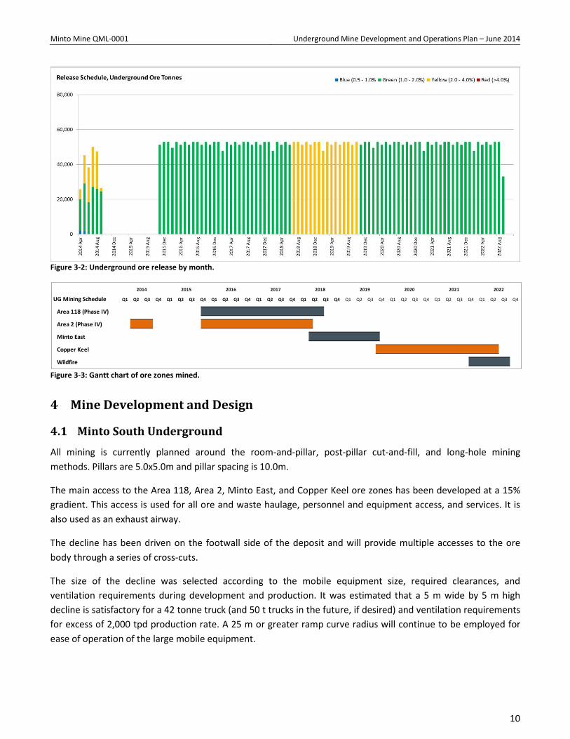
The mining rate is currently planned at approximately 1,800 tonnes per day. A graph of ore release by month is presented in Figure 3-2; the underground production may be brought forward in time as part of the ongoing engineering optimization efforts.
There is a gap in underground ore release between the completion of the M-zone in September 2014 and the resumption of mining in the Area 2 and Area 118 zones. Due to the high-grade ore released by the Minto North pit in 2015. Mining activities will be suspended during this period; however, development will resume approximately seven months before ore production.
9
Minto Mine QML-0001 Underground Mine Development and Operations Plan – June 2014
Figure 3-2: Underground ore release by month.
Figure 3-3: Gantt chart of ore zones mined.
4 Mine Development and Design
4.1 Minto South Underground All mining is currently planned around the room-and-pillar, post-pillar cut-and-fill, and long-hole mining methods. Pillars are 5.0x5.0m and pillar spacing is 10.0m.
The main access to the Area 118, Area 2, Minto East, and Copper Keel ore zones has been developed at a 15% gradient. This access is used for all ore and waste haulage, personnel and equipment access, and services. It is also used as an exhaust airway.
The decline has been driven on the footwall side of the deposit and will provide multiple accesses to the ore body through a series of cross-cuts.
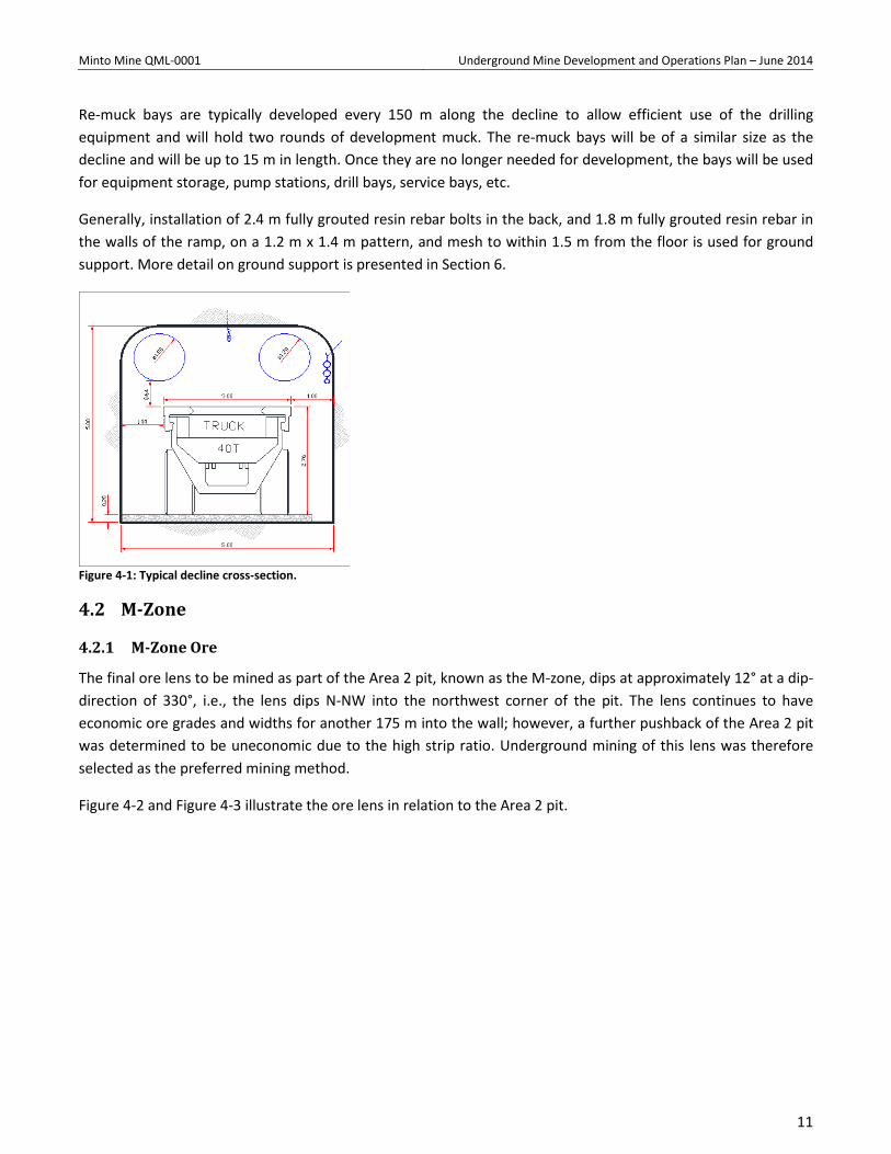
The size of the decline was selected according to the mobile equipment size, required clearances, and ventilation requirements during development and production. It was estimated that a 5 m wide by 5 m high decline is satisfactory for a 42 tonne truck (and 50 t trucks in the future, if desired) and ventilation requirements for excess of 2,000 tpd production rate. A 25 m or greater ramp curve radius will continue to be employed for ease of operation of the large mobile equipment.
UG Mining Schedule
Area 118 (Phase IV)
Area 2 (Phase IV)
Minto East
Copper Keel
Wildfire
2022
Q1 Q2 Q3 Q4
2020 2021
Q1 Q2 Q3 Q4 Q1 Q2 Q3 Q4
2014 2015 2016 2017 2018 2019
Q4Q1 Q2 Q3 Q4 Q1 Q2 Q3 Q4 Q1 Q2 Q3 Q4Q1 Q2 Q3 Q4 Q1 Q2 Q3 Q4 Q1 Q2 Q3
10
Minto Mine QML-0001 Underground Mine Development and Operations Plan – June 2014
Re-muck bays are typically developed every 150 m along the decline to allow efficient use of the drilling equipment and will hold two rounds of development muck. The re-muck bays will be of a similar size as the decline and will be up to 15 m in length. Once they are no longer needed for development, the bays will be used for equipment storage, pump stations, drill bays, service bays, etc.
Generally, installation of 2.4 m fully grouted resin rebar bolts in the back, and 1.8 m fully grouted resin rebar in the walls of the ramp, on a 1.2 m x 1.4 m pattern, and mesh to within 1.5 m from the floor is used for ground support. More detail on ground support is presented in Section 6.
Figure 4-1: Typical decline cross-section.
4.2 M-Zone
4.2.1 M-Zone Ore
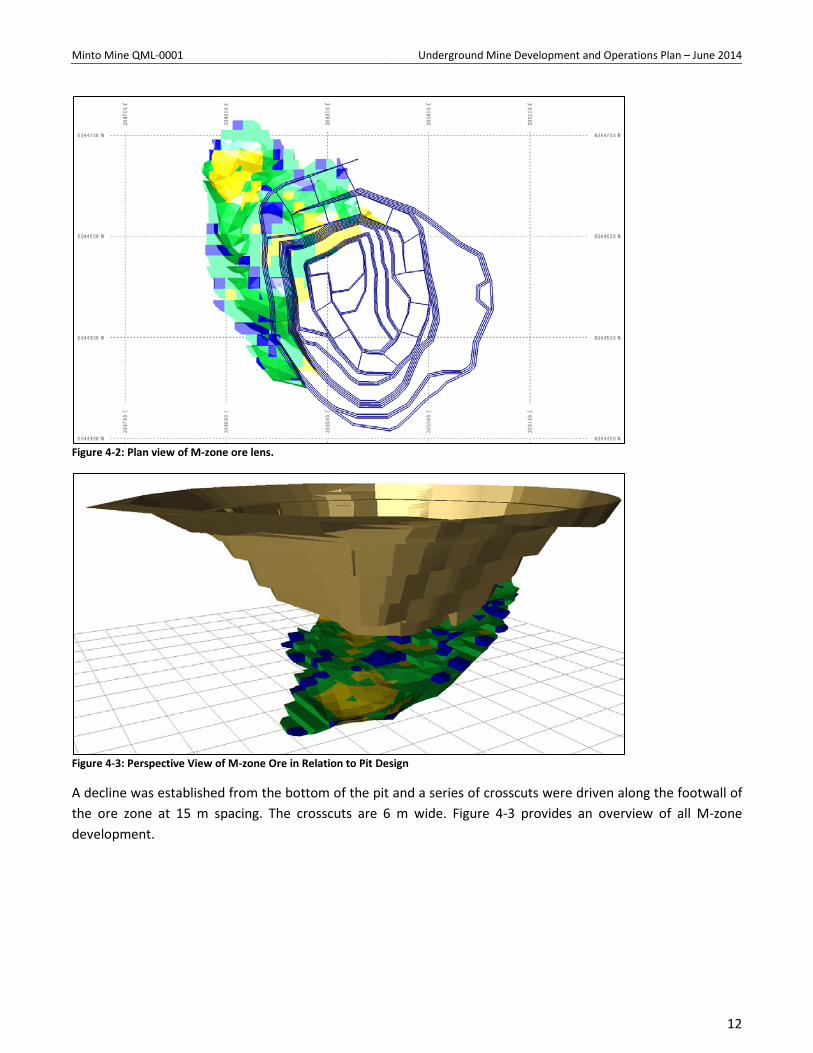
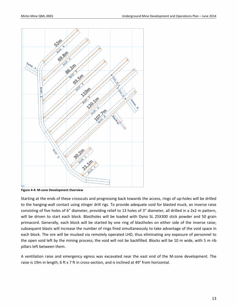
The final ore lens to be mined as part of the Area 2 pit, known as the M-zone, dips at approximately 12° at a dip-direction of 330°, i.e., the lens dips N-NW into the northwest corner of the pit. The lens continues to have economic ore grades and widths for another 175 m into the wall; however, a further pushback of the Area 2 pit was determined to be uneconomic due to the high strip ratio. Underground mining of this lens was therefore selected as the preferred mining method.
Figure 4-2 and Figure 4-3 illustrate the ore lens in relation to the Area 2 pit.
11
Minto Mine QML-0001 Underground Mine Development and Operations Plan – June 2014
Figure 4-2: Plan view of M-zone ore lens.
Figure 4-3: Perspective View of M-zone Ore in Relation to Pit Design
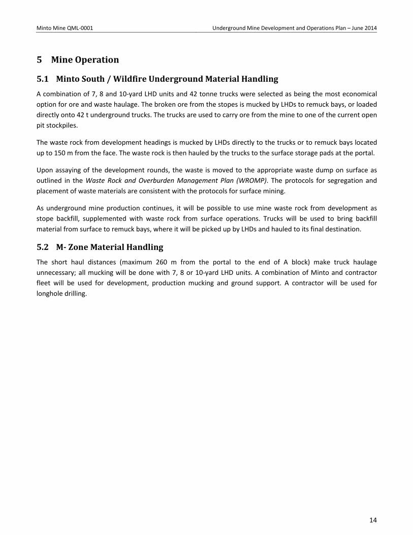
A decline was established from the bottom of the pit and a series of crosscuts were driven along the footwall of the ore zone at 15 m spacing. The crosscuts are 6 m wide. Figure 4-3 provides an overview of all M-zone development.
12
Minto Mine QML-0001 Underground Mine Development and Operations Plan – June 2014
Figure 4-4: M-zone Development Overview
Starting at the ends of these crosscuts and progressing back towards the access, rings of up-holes will be drilled to the hanging-wall contact using stinger drill rigs. To provide adequate void for blasted muck, an inverse raise consisting of five holes of 6” diameter, providing relief to 13 holes of 3” diameter, all drilled in a 2x2 m pattern, will be driven to start each block. Blastholes will be loaded with Dyno SL 25X300 stick powder and 50 grain primacord. Generally, each block will be started by one ring of blastholes on either side of the inverse raise; subsequent blasts will increase the number of rings fired simultaneously to take advantage of the void space in each block. The ore will be mucked via remotely operated LHD, thus eliminating any exposure of personnel to the open void left by the mining process; the void will not be backfilled. Blocks will be 10 m wide, with 5 m rib pillars left between them.
A ventilation raise and emergency egress was excavated near the east end of the M-zone development. The raise is 19m in length, 6 ft x 7 ft in cross-section, and is inclined at 49° from horizontal.
13
Minto Mine QML-0001 Underground Mine Development and Operations Plan – June 2014
5 Mine Operation
5.1 Minto South / Wildfire Underground Material Handling A combination of 7, 8 and 10-yard LHD units and 42 tonne trucks were selected as being the most economical option for ore and waste haulage. The broken ore from the stopes is mucked by LHDs to remuck bays, or loaded directly onto 42 t underground trucks. The trucks are used to carry ore from the mine to one of the current open pit stockpiles.
The waste rock from development headings is mucked by LHDs directly to the trucks or to remuck bays located up to 150 m from the face. The waste rock is then hauled by the trucks to the surface storage pads at the portal.
Upon assaying of the development rounds, the waste is moved to the appropriate waste dump on surface as outlined in the Waste Rock and Overburden Management Plan (WROMP). The protocols for segregation and placement of waste materials are consistent with the protocols for surface mining.
As underground mine production continues, it will be possible to use mine waste rock from development as stope backfill, supplemented with waste rock from surface operations. Trucks will be used to bring backfill material from surface to remuck bays, where it will be picked up by LHDs and hauled to its final destination.
5.2 M- Zone Material Handling The short haul distances (maximum 260 m from the portal to the end of A block) make truck haulage unnecessary; all mucking will be done with 7, 8 or 10-yard LHD units. A combination of Minto and contractor fleet will be used for development, production mucking and ground support. A contractor will be used for longhole drilling.
14
Minto Mine QML-0001 Underground Mine Development and Operations Plan – June 2014
6 Underground Geotechnical Assessment Geotechnical characterization and design work has been carried out by SRK Consulting Ltd. and Itasca Consulting Group Inc. for the Area 2 and Area 118 zones. A ground control management plan was developed and implemented in 2013 and has been used for all underground development to date.
The following points (italicized) are excerpts from the SRK Phase V Prefeasibility Study:
Resource continuity
The (mineralized) zones bifurcate, which means that a mineralized zone can contain a significant amount of waste, or that thinner ore zones can merge with larger zones. A bifurcating geometry complicates geological modelling and may expect to increase internal dilution.
The width and dip of mineralized zones are locally variable. The zones therefore appear to pinch-and-swell. The change in thickness might be as much as an order of magnitude over less than 30 m in horizontal distance.
At least some of the irregularity in the geometry and thickness of the mineralized zones is due to small-scale and large-scale structural displacements.
Deposit boundaries
The boundary between Area 2 and Area 118 zones has been modelled as a fault. The drill hole intersections are of sufficient density to show the position of the fault accurately. Two additional faults have been modelled in order to explain intersection positions in Area 118, and these faults divide the Area 118 resource into three domains.
No study has been done on the drill core in order to define the characteristics of the faults. There are indications that these faults have the characteristics of high strain shear zones, rather than brittle structures.
The main geotechnical points from this are: • Mineralization is considered be variable both in thickness, dip, and lateral continuity; • Displacements occur through mineralization on the meter scale; • Major boundary fault zones are present in Area 2/118 areas and have been modeled in 3D. A
detailed structural model and structural characterization have not been completed, and; • There is potential for fault zones to be present in the Copper Keel area.
6.1 Hydrogeological Assessment A hydrogeological assessment has not been completed to define the potential inflows to the underground workings from large and small-scale structures. Minto’s experience with open pit mining has been that static groundwater is encountered in blastholes, but that surface runoff is the major driver of pit dewatering requirements. Inflows encountered in the Minto South Underground development to date have been associated with several discrete water-bearing faults and with un-grouted diamond drillholes. No unmanageable inflows have been intersected and a common sump and pump dewatering system has been used without any grouting work required.
15
Minto Mine QML-0001 Underground Mine Development and Operations Plan – June 2014
6.2 Area 118, Area 2, Minto East, Copper Keel and Wild Fire Underground
6.2.1 Mining Method – Geotechnical Considerations
Due to the mineralized zone variable continuity SRK has recommended that a ‘random room and pillar’ mining method is adopted in some areas. This involves driving development size headings through identified mining areas on a contour, and moving left or right (no change in elevation) to keep the hanging wall contact of mineralization in the back of the drive. These headings are completed under geological control only. Infill drilling is then completed from cut-outs driven from the headings. Based on these results a standard room and pillar layout can then be established, and extraction is achieved on the retreat under supported ground (slashing out to full span width). The decision on whether to support the full span or not can be made as the headings are advanced.
The advantages of this method allow the definition and understanding of the orebody character and geometry to be established on advance: therefore the mining method defines the orebody. Additionally back and pillar support can be installed on the advance with the understanding that long term access could be required through the development headings. In essence the mineralization and rock mass is characterized on the advance, and the mining spans and level of extraction determined. This is then extracted on the retreat.
SRK estimated an extraction ratio of around 75% should be anticipated. This would meet the 1:1 pillar height criteria. Extraction ratios in faulted/broken ground areas will need to be reduced locally based on the prevailing rock mass conditions.
Mzone
6.2.2 Orebody Geometry
Analyses carried out by SRK were based on the following orebody characteristics:
Thickness: 5 to 20m, generally less than 15m. Span: 50 to 160m, generally less than 100m. Dip: 0 to 40° from horizontal, generally less than 10°.
The shapes show poor continuity between areas, some of which appear to be based on the result of a single drill hole. It is expected that these could become more continuous once tighter drill hole spacing, underground exposure, and a proper understanding of the ore body geometry is achieved.
6.2.3 Rock Mass Assessment
Bieniawski Rock Mass Rating (RMR89) and Barton Q values were evaluated for the underground zones. An average RMR89 of 65 and Q of 10 were estimated. Experience in the Area 2 (M-Zone) underground to date indicates better than expected rock quality, with an average RMR89 of 77 and Q of 15 based on limited mapping completed. Mining guidelines have been developed from empirical, analytical, numerical models and practical experience.
16
Minto Mine QML-0001 Underground Mine Development and Operations Plan – June 2014
6.2.4 Underground Excavation Design
Excavation design has been completed for man entry spans and pillars on based empirical guidelines adjusted to the anticipated rock mass characteristics. The following is a summary of the findings:
• Development headings: 5 m W x 5 m H arch back
• Rooms: 10 m span limit with pattern support
• Pillars: 5 m W x 5 m H
5m W x >5 m H support or fill required
A design span limit of 10m has been recommended for mining in areas of good rock mass quality. Without underground exposures an initial conservative extraction ratio of around 75% was anticipated to account for major structures, adverse small scale structure, or zones of lower rock mass quality. This would meet the 1:1 pillar height criteria. The required ground support systems to increase spans through zones of reduced rock quality should be tested during early mine development.
For most mining areas, superimposed 5m by 5m pillars are planned to limit spans to 10m. These spans would be mined using a cut height of 5m. Pillars over 5m height should be assessed on an individual case basis, and rock support or fill should be utilized.
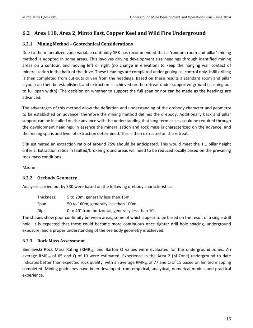
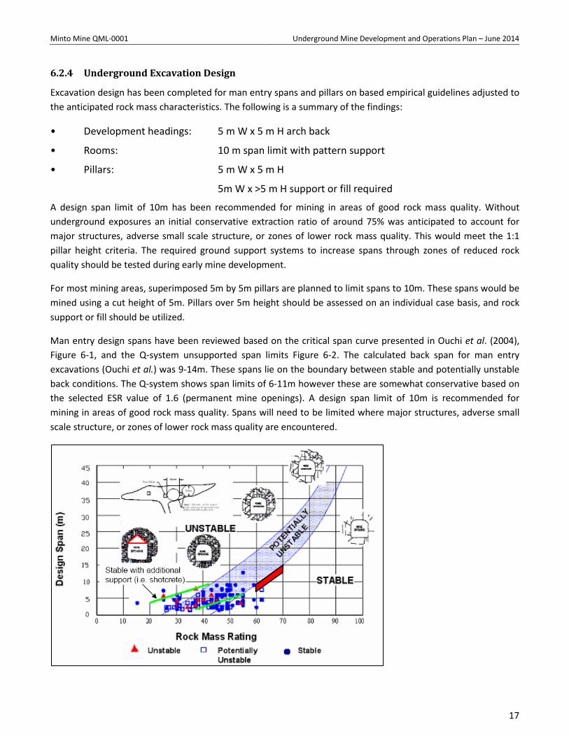
Man entry design spans have been reviewed based on the critical span curve presented in Ouchi et al. (2004), Figure 6-1, and the Q-system unsupported span limits Figure 6-2. The calculated back span for man entry excavations (Ouchi et al.) was 9-14m. These spans lie on the boundary between stable and potentially unstable back conditions. The Q-system shows span limits of 6-11m however these are somewhat conservative based on the selected ESR value of 1.6 (permanent mine openings). A design span limit of 10m is recommended for mining in areas of good rock mass quality. Spans will need to be limited where major structures, adverse small scale structure, or zones of lower rock mass quality are encountered.
17
Minto Mine QML-0001 Underground Mine Development and Operations Plan – June 2014
Figure 6-1: Ouchi Critical Span Curve
Figure 6-2: Q-system unsupported span limits for permanent openings (ESR=1.6).
18
Minto Mine QML-0001 Underground Mine Development and Operations Plan – June 2014
6.2.5 Pillar Design and Stability Assessment
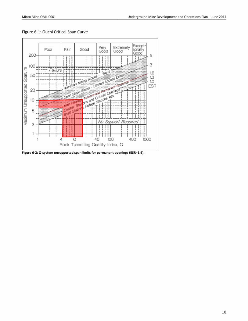
Pillar analyses were conducted using tributary area loads and several pillar equations that incorporate pillar width to height ratios. The Holland equation:
Pillar Strength = UCS (W/H)0.5
was used to evaluate 5x5 m pillars and 10 m rooms (Table 6-1). Practical experience and the factor of safety indicate this configuration to be reasonable for pillars up to about 7 m height. Taller pillars will need to be reinforced or supported by fill to maintain stability.
Table 6-1: Pillar Calculations
Depth (m)
Pillar W1 (m)
Room R1 (m)
Pillar Height (m)
W/H Ratio Pillar Strength (MPa)
Extraction Ratio (%)
Factor of Safety
300 5 10 5 1 120 89 1.7 300 5 10 7 0.7 101 89 1.4 300 5 10 10 0.5 85 89 1.2 300 5 10 15 0.3 69 89 1 For most mining areas, superimposed 5x5 m pillars are planned to limit spans to 10 m. These spans would be mined using a cut height of 5 m. Pillars over 5m height should be assessed on an individual case basis, and rock support or fill should be utilized. Based on the empirical evaluations of Holland (1964) and Obert and Duvall (1967), these pillars are considered to provide the required support.
6.3 Fill In thicker parts of mineralization, waste rock backfill will be used to provide support to tall slender pillars, as well as bolt and shotcrete to floor where required. Tall slender pillars will be developed following benching of the floor where orebody thicknesses are greater than 5 m. As the tops of the pillars will no longer be accessible by mining equipment, fill will be required both for support and access reasons through mined areas.
The 5 m stope cuts will be filled with waste rock, from underground mine development or waste from the Area 2 pit, to provide the necessary hanging wall and post pillar support. The waste rock will be placed by 42 T trucks in waste storage areas located at the stope access level and then placed in the stopes by LHD equipment. Waste fill will be pushed tight to the hanging wall and to the back by a push plate attached to the scoop. Stope floor leveling will be established on the next cut and dilution controlled by grade.
19
Minto Mine QML-0001 Underground Mine Development and Operations Plan – June 2014
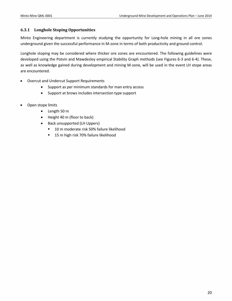
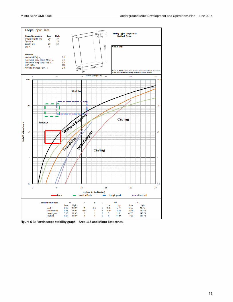
6.3.1 Longhole Stoping Opportunities
Minto Engineering department is currently studying the opportunity for Long-hole mining in all ore zones underground given the successful performance in M-zone in terms of both productivity and ground control.
Longhole stoping may be considered where thicker ore zones are encountered. The following guidelines were developed using the Potvin and Mawdesley empirical Stability Graph methods (see Figures 6-3 and 6-4). These, as well as knowledge gained during development and mining M-zone, will be used in the event LH stope areas are encountered.
• Overcut and Undercut Support Requirements • Support as per minimum standards for man entry access • Support at brows includes intersection type support
• Open stope limits
• Length 50 m • Height 40 m (floor to back) • Back unsupported (LH Uppers) 10 m moderate risk 50% failure likelihood 15 m high risk 70% failure likelihood
20
Minto Mine QML-0001 Underground Mine Development and Operations Plan – June 2014
Figure 6-3: Potvin stope stability graph—Area 118 and Minto East zones.
21
Minto Mine QML-0001 Underground Mine Development and Operations Plan – June 2014
Figure 6-4: Mawdsley stope probability-of-failure graph—Area 118 zone.
22
Minto Mine QML-0001 Underground Mine Development and Operations Plan – June 2014
6.3.2 Kinematic Wedge Analysis
A wedge analysis has been completed by SRK to understand the potential geometries and sizes of blocks formed during mining. The room and pillar mining method means that all headings are essentially ‘development’ (based on spans) and as such have been considered in the analysis. A drift size of 5x5 m has been used to date in the main ramp with a wider span of 10m also considered. These analyses will be updated with information collected during development as part of regular reviews and updates to the ground control management plan.
6.3.3 Lateral Development
Key observations from the analysis are:
• The formation of potentially unstable wedges occurs in the back and sidewalls of the excavation related to the three primary joint sets.
• The least favourable orientation for lateral development occurs between 340° and 40° azimuth. • The apex height of the identified wedge is controlled by the plunge and span of the development. This
height is generally less than 3 m for a 5 m span. • Larger wedges are generated with an increased span of 10 m. These will be identified during mining of
the primary heading, and will need to be well supported prior to slashing out on retreat. • The ground support recommendations will provide sufficient support pressure to prevent the wedges
generated from being released. Additional support maybe required dependent on the plunge of infrastructure relative to small scale structures.
6.3.4 Vertical Development
Key observations from the analysis are:
• Large wedges are formed in all the walls and back of the vertical excavations (i.e. vent raises). • The geometry is the wedge is controlled by the plunge of the infrastructure. • The apex height of the identified wedges is generally less than 0.8 m and support recommendations
will provide sufficient support pressure to prevent the wedges identified from being released.
23
Minto Mine QML-0001 Underground Mine Development and Operations Plan – June 2014
6.3.5 Ground Support Requirements
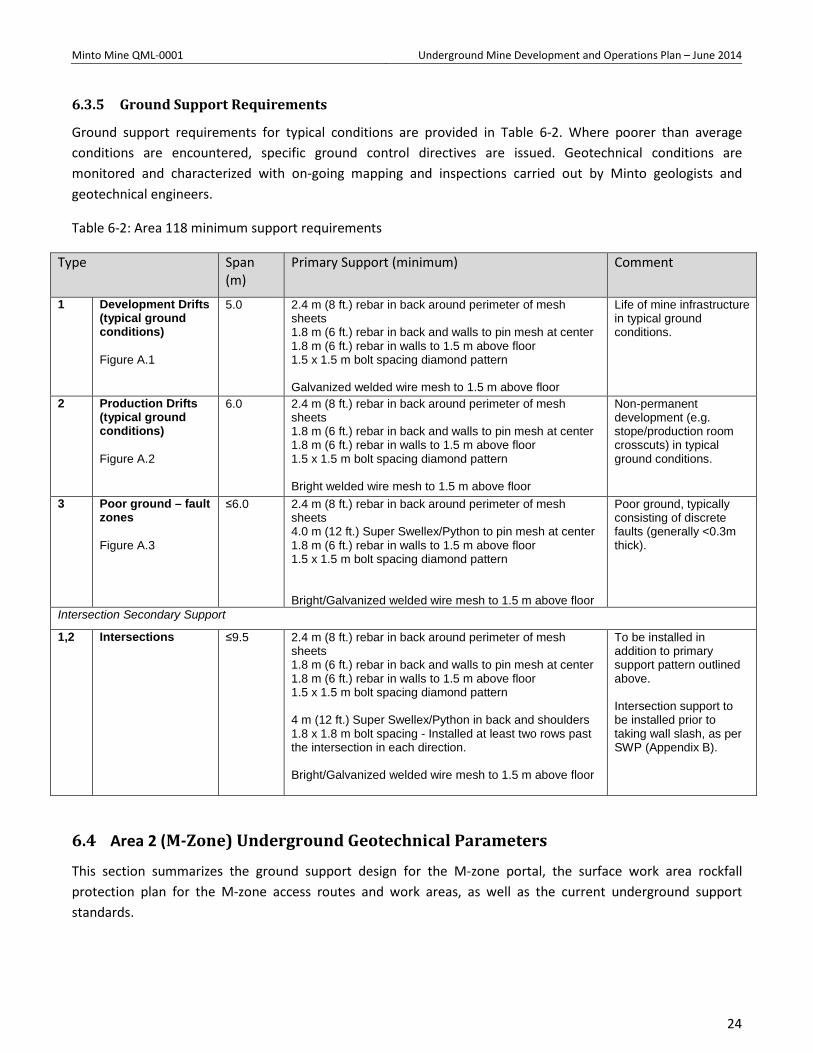
Ground support requirements for typical conditions are provided in Table 6-2. Where poorer than average conditions are encountered, specific ground control directives are issued. Geotechnical conditions are monitored and characterized with on-going mapping and inspections carried out by Minto geologists and geotechnical engineers.
Table 6-2: Area 118 minimum support requirements
Type Span (m)
Primary Support (minimum) Comment
1 Development Drifts (typical ground conditions) Figure A.1
5.0 2.4 m (8 ft.) rebar in back around perimeter of mesh sheets 1.8 m (6 ft.) rebar in back and walls to pin mesh at center 1.8 m (6 ft.) rebar in walls to 1.5 m above floor 1.5 x 1.5 m bolt spacing diamond pattern Galvanized welded wire mesh to 1.5 m above floor
Life of mine infrastructure in typical ground conditions.
2 Production Drifts (typical ground conditions) Figure A.2
6.0 2.4 m (8 ft.) rebar in back around perimeter of mesh sheets 1.8 m (6 ft.) rebar in back and walls to pin mesh at center 1.8 m (6 ft.) rebar in walls to 1.5 m above floor 1.5 x 1.5 m bolt spacing diamond pattern Bright welded wire mesh to 1.5 m above floor
Non-permanent development (e.g. stope/production room crosscuts) in typical ground conditions.
3 Poor ground – fault zones Figure A.3
≤6.0 2.4 m (8 ft.) rebar in back around perimeter of mesh sheets 4.0 m (12 ft.) Super Swellex/Python to pin mesh at center 1.8 m (6 ft.) rebar in walls to 1.5 m above floor 1.5 x 1.5 m bolt spacing diamond pattern Bright/Galvanized welded wire mesh to 1.5 m above floor
Poor ground, typically consisting of discrete faults (generally <0.3m thick).
Intersection Secondary Support
1,2 Intersections ≤9.5 2.4 m (8 ft.) rebar in back around perimeter of mesh sheets 1.8 m (6 ft.) rebar in back and walls to pin mesh at center 1.8 m (6 ft.) rebar in walls to 1.5 m above floor 1.5 x 1.5 m bolt spacing diamond pattern 4 m (12 ft.) Super Swellex/Python in back and shoulders 1.8 x 1.8 m bolt spacing - Installed at least two rows past the intersection in each direction. Bright/Galvanized welded wire mesh to 1.5 m above floor
To be installed in addition to primary support pattern outlined above. Intersection support to be installed prior to taking wall slash, as per SWP (Appendix B).
6.4 Area 2 (M-Zone) Underground Geotechnical Parameters
This section summarizes the ground support design for the M-zone portal, the surface work area rockfall protection plan for the M-zone access routes and work areas, as well as the current underground support standards.
24
Minto Mine QML-0001 Underground Mine Development and Operations Plan – June 2014
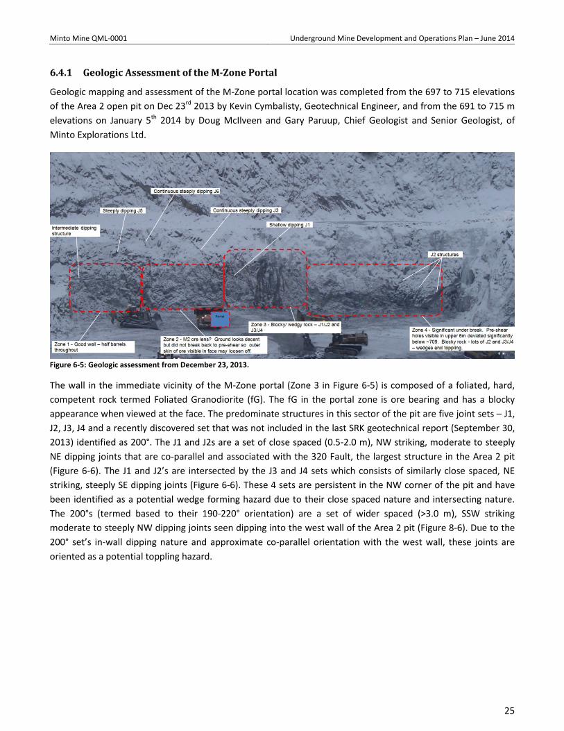
6.4.1 Geologic Assessment of the M-Zone Portal
Geologic mapping and assessment of the M-Zone portal location was completed from the 697 to 715 elevations of the Area 2 open pit on Dec 23rd 2013 by Kevin Cymbalisty, Geotechnical Engineer, and from the 691 to 715 m elevations on January 5th 2014 by Doug McIlveen and Gary Paruup, Chief Geologist and Senior Geologist, of Minto Explorations Ltd.
Figure 6-5: Geologic assessment from December 23, 2013.
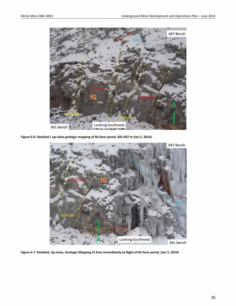
The wall in the immediate vicinity of the M-Zone portal (Zone 3 in Figure 6-5) is composed of a foliated, hard, competent rock termed Foliated Granodiorite (fG). The fG in the portal zone is ore bearing and has a blocky appearance when viewed at the face. The predominate structures in this sector of the pit are five joint sets – J1, J2, J3, J4 and a recently discovered set that was not included in the last SRK geotechnical report (September 30, 2013) identified as 200°. The J1 and J2s are a set of close spaced (0.5-2.0 m), NW striking, moderate to steeply NE dipping joints that are co-parallel and associated with the 320 Fault, the largest structure in the Area 2 pit (Figure 6-6). The J1 and J2’s are intersected by the J3 and J4 sets which consists of similarly close spaced, NE striking, steeply SE dipping joints (Figure 6-6). These 4 sets are persistent in the NW corner of the pit and have been identified as a potential wedge forming hazard due to their close spaced nature and intersecting nature. The 200°s (termed based to their 190-220° orientation) are a set of wider spaced (>3.0 m), SSW striking moderate to steeply NW dipping joints seen dipping into the west wall of the Area 2 pit (Figure 8-6). Due to the 200° set’s in-wall dipping nature and approximate co-parallel orientation with the west wall, these joints are oriented as a potential toppling hazard.
25
Minto Mine QML-0001 Underground Mine Development and Operations Plan – June 2014
Figure 6-6: Detailed / up-close geologic mapping of M-Zone portal, 691-697 m (Jan 5, 2014).
Figure 6-7: Detailed, Up-close, Geologic Mapping of Area Immediately to Right of M-Zone portal, (Jan 5, 2014)
26
Minto Mine QML-0001 Underground Mine Development and Operations Plan – June 2014
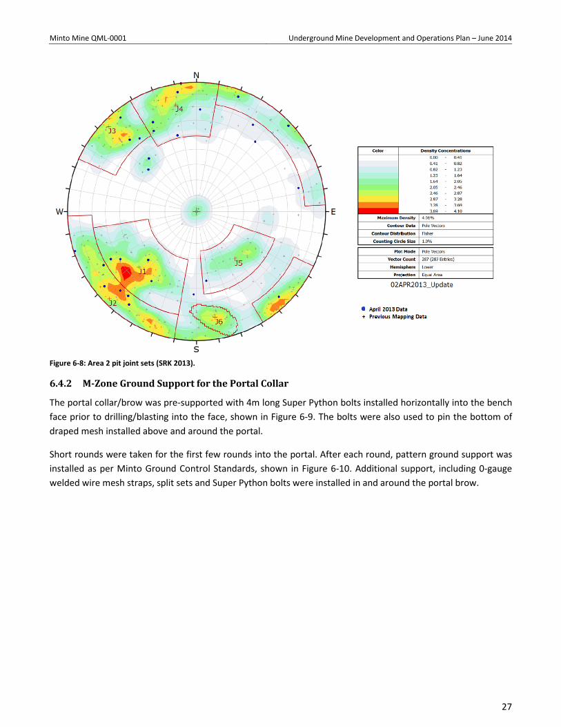
Figure 6-8: Area 2 pit joint sets (SRK 2013).
6.4.2 M-Zone Ground Support for the Portal Collar
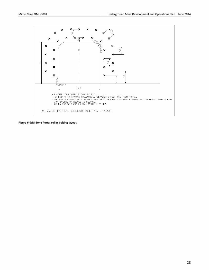
The portal collar/brow was pre-supported with 4m long Super Python bolts installed horizontally into the bench face prior to drilling/blasting into the face, shown in Figure 6-9. The bolts were also used to pin the bottom of draped mesh installed above and around the portal.
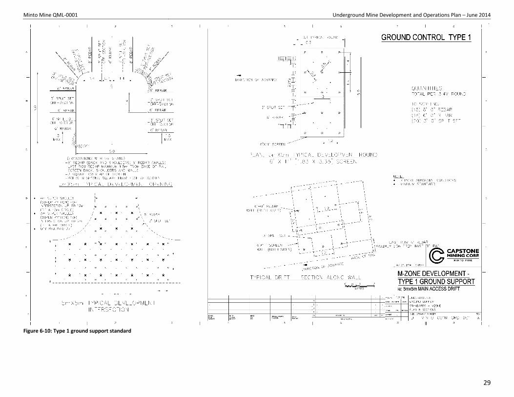
Short rounds were taken for the first few rounds into the portal. After each round, pattern ground support was installed as per Minto Ground Control Standards, shown in Figure 6-10. Additional support, including 0-gauge welded wire mesh straps, split sets and Super Python bolts were installed in and around the portal brow.
27
Minto Mine QML-0001 Underground Mine Development and Operations Plan – June 2014
Figure 6-9:M-Zone Portal collar bolting layout
28
Minto Mine QML-0001 Underground Mine Development and Operations Plan – June 2014
Figure 6-10: Type 1 ground support standard
29
Minto Mine QML-0001 Underground Mine Development and Operations Plan – June 2014
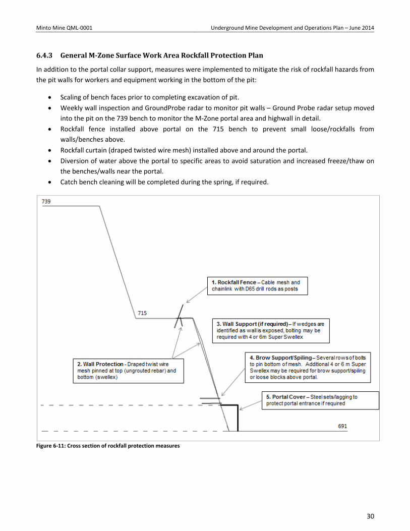
6.4.3 General M-Zone Surface Work Area Rockfall Protection Plan
In addition to the portal collar support, measures were implemented to mitigate the risk of rockfall hazards from the pit walls for workers and equipment working in the bottom of the pit:
• Scaling of bench faces prior to completing excavation of pit. • Weekly wall inspection and GroundProbe radar to monitor pit walls – Ground Probe radar setup moved
into the pit on the 739 bench to monitor the M-Zone portal area and highwall in detail. • Rockfall fence installed above portal on the 715 bench to prevent small loose/rockfalls from
walls/benches above. • Rockfall curtain (draped twisted wire mesh) installed above and around the portal. • Diversion of water above the portal to specific areas to avoid saturation and increased freeze/thaw on
the benches/walls near the portal. • Catch bench cleaning will be completed during the spring, if required.
Figure 6-11: Cross section of rockfall protection measures
30
Minto Mine QML-0001 Underground Mine Development and Operations Plan – June 2014
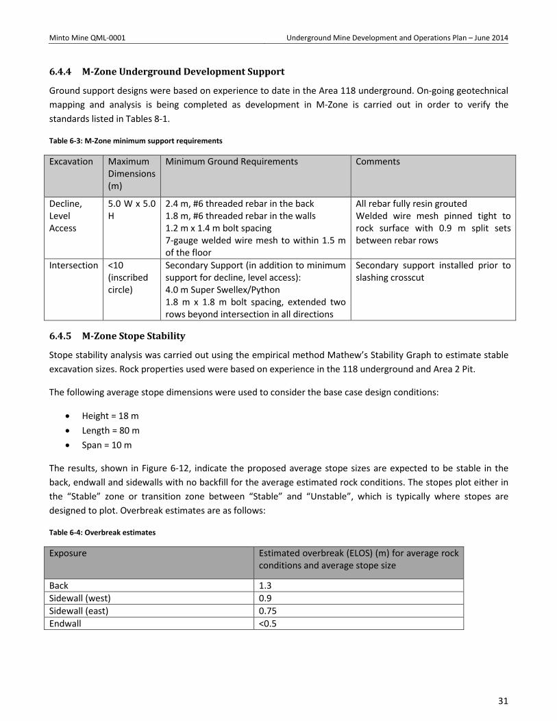
6.4.4 M-Zone Underground Development Support
Ground support designs were based on experience to date in the Area 118 underground. On-going geotechnical mapping and analysis is being completed as development in M-Zone is carried out in order to verify the standards listed in Tables 8-1.
Table 6-3: M-Zone minimum support requirements
Excavation Maximum Dimensions (m)
Minimum Ground Requirements Comments
Decline, Level Access
5.0 W x 5.0 H
2.4 m, #6 threaded rebar in the back 1.8 m, #6 threaded rebar in the walls 1.2 m x 1.4 m bolt spacing 7-gauge welded wire mesh to within 1.5 m of the floor
All rebar fully resin grouted Welded wire mesh pinned tight to rock surface with 0.9 m split sets between rebar rows
Intersection <10 (inscribed circle)
Secondary Support (in addition to minimum support for decline, level access): 4.0 m Super Swellex/Python 1.8 m x 1.8 m bolt spacing, extended two rows beyond intersection in all directions
Secondary support installed prior to slashing crosscut
6.4.5 M-Zone Stope Stability
Stope stability analysis was carried out using the empirical method Mathew’s Stability Graph to estimate stable excavation sizes. Rock properties used were based on experience in the 118 underground and Area 2 Pit.
The following average stope dimensions were used to consider the base case design conditions:
• Height = 18 m • Length = 80 m • Span = 10 m
The results, shown in Figure 6-12, indicate the proposed average stope sizes are expected to be stable in the back, endwall and sidewalls with no backfill for the average estimated rock conditions. The stopes plot either in the “Stable” zone or transition zone between “Stable” and “Unstable”, which is typically where stopes are designed to plot. Overbreak estimates are as follows:
Table 6-4: Overbreak estimates
Exposure Estimated overbreak (ELOS) (m) for average rock conditions and average stope size
Back 1.3 Sidewall (west) 0.9 Sidewall (east) 0.75 Endwall <0.5
31
Minto Mine QML-0001 Underground Mine Development and Operations Plan – June 2014
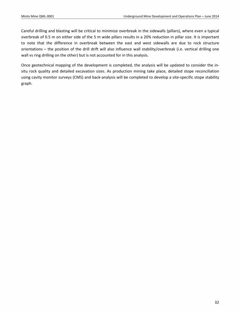
Careful drilling and blasting will be critical to minimize overbreak in the sidewalls (pillars), where even a typical overbreak of 0.5 m on either side of the 5 m wide pillars results in a 20% reduction in pillar size. It is important to note that the difference in overbreak between the east and west sidewalls are due to rock structure orientations – the position of the drill drift will also influence wall stability/overbreak (i.e. vertical drilling one wall vs ring drilling on the other) but is not accounted for in this analysis.
Once geotechnical mapping of the development is completed, the analysis will be updated to consider the in-situ rock quality and detailed excavation sizes. As production mining take place, detailed stope reconciliation using cavity monitor surveys (CMS) and back-analysis will be completed to develop a site-specific stope stability graph.
32

Minto Mine QML-0001 Underground Mine Development and Operations Plan – June 2014
Figure 6-12: Stope stability for average conditions
33
Minto Mine QML-0001 Underground Mine Development and Operations Plan – June 2014
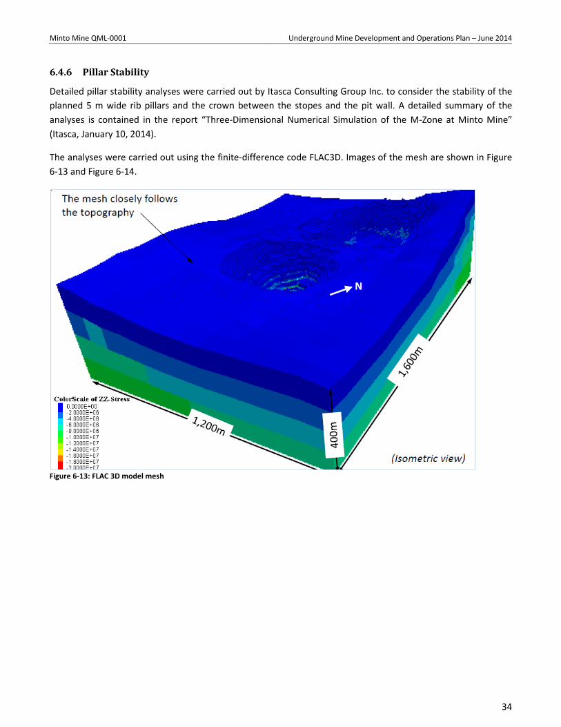
6.4.6 Pillar Stability
Detailed pillar stability analyses were carried out by Itasca Consulting Group Inc. to consider the stability of the planned 5 m wide rib pillars and the crown between the stopes and the pit wall. A detailed summary of the analyses is contained in the report “Three-Dimensional Numerical Simulation of the M-Zone at Minto Mine” (Itasca, January 10, 2014).
The analyses were carried out using the finite-difference code FLAC3D. Images of the mesh are shown in Figure 6-13 and Figure 6-14.
Figure 6-13: FLAC 3D model mesh
34
Minto Mine QML-0001 Underground Mine Development and Operations Plan – June 2014
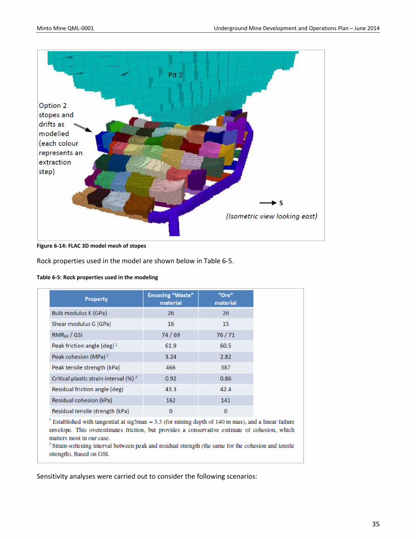
Figure 6-14: FLAC 3D model mesh of stopes
Rock properties used in the model are shown below in Table 6-5.
Table 6-5: Rock properties used in the modeling
Sensitivity analyses were carried out to consider the following scenarios:
35
Minto Mine QML-0001 Underground Mine Development and Operations Plan – June 2014
• Weakened, blast damaged zone around the excavations. This was analyzed using a zone of weaker rock properties approximately 3.5m around all underground excavations and 10m around the pit wall.
• Rotated in-situ stress orientation. • Lower friction angle in both ore and waste to consider weaker than expected rock quality. • Reduced critical plastic strain interval to consider brittle tensile failure of the rock mass. • Complete removal of the central rib pillar to consider large-scale stability in the event of a pillar failure.
Conclusions from the analyses included the following (Itasca, 2014):
1. The M-Zone rib pillars and stope roofs are mostly stable (i.e., show limited yielding) as modeled for both options 1 and 2, even when taking into account possible blast damage by assigning lower strength properties to the rock mass immediately around the underground excavations and open pit, or even assuming the complete failure (total removal) of a central rib pillar. This is mostly due to the low vertical stress in proximity to the open pit, relatively high horizontal stresses that provide confinement to the crown pillar (with the Base Case stress orientation) and fairly strong rock mass properties. No stope-scale runaway failure has been indicated in any of the scenarios we examined.
2. We cannot over-emphasize how crucial good blasting procedures (in terms of limited back-break and damage to the surrounding rock mass) will be in order to minimize the extent of the weaker D = 1 volume.
3. The bull nose near the stope closest to the open pit and the access to the underground area remains a concern for both options. Active yielding can be observed in these areas for both base cases and all the sensitivity analyses. The issue is critically important with regard to maintaining access to the M-Zone.
4. Geomechanical issues are expected mainly on the south side, between the stopes and the pit. Stopes with sequence numbers in the 30’s in Option 1 and in the last four panels on the south side in Option 2 generally show a greater degree of interaction with the open pit due to their proximity to it. The crown pillar and walls in this area are likely to be weakened by the yielding from the stopes themselves combined with that from the pit above. Keeping these roofs stable may be more challenging. Instability in the open pit also could occur as a result of this yielding.
5. There remains some debate on critical plastic strains and the “correct” way to implement them for cohesion and tensile strength loss in inelastic strain-softening simulations. As a result, we recommend keeping the results from the brittle runs in mind, which are more conservative.
6. Although the numerical results do not show severe stress-related failure in the rock mass modeled as a continuum, the stress relaxation indicated around the excavations easily could lead to structural instability (as in the ramp). This aspect is NOT covered in the FLAC3D model. As a result, it will be crucial to assess whether persistent weak structural discontinuities extend around M-Zone, which could significantly affect the stope ribs and roofs. Persistent discontinuities that would delineate kinematically unstable blocks could have a very strong negative effect on the behavior of the excavations and the mining conditions in M-Zone. Considering the structural fabric in the pit above, this aspect needs to be resolved.
Based on these conclusions, Minto will be carrying out the following verification work:
36
Minto Mine QML-0001 Underground Mine Development and Operations Plan – June 2014
• Detailed geotechnical mapping (structural and rock quality) will be carried out throughout the development. Based on this information the empirical stope stability analysis will be revised and kinematic analyses will be performed to consider structural instability not explicitly assessed in the FLAC3D model. If rock mass quality is significantly different than estimated in the numerical models, the models will be re-run with revised properties.
• As stoping is carried out, CMS will be performed to monitor performance of the backs and rib pillars. If performance is significantly different than predicted by the numerical models, the models will be re-run and calibrated to the actual conditions. Where significant overbreak occurs, particularly in a rib pillar, planned stopes will be revised to prevent over-extraction.
• Based on the performance of the initial stopes (further away from the pit wall), review of the layout for stopes (I and H) near the crown pillar will be carried out. This may include additional instrumentation and/or ground support installed into the crown pillar from surface.
37
Minto Mine QML-0001 Underground Mine Development and Operations Plan – June 2014
7 Ventilation, Ancillary Infrastructure, and Dewatering,
7.1 Mine Ventilation
7.1.1 Minto South Portal Ventilation – Stage 1
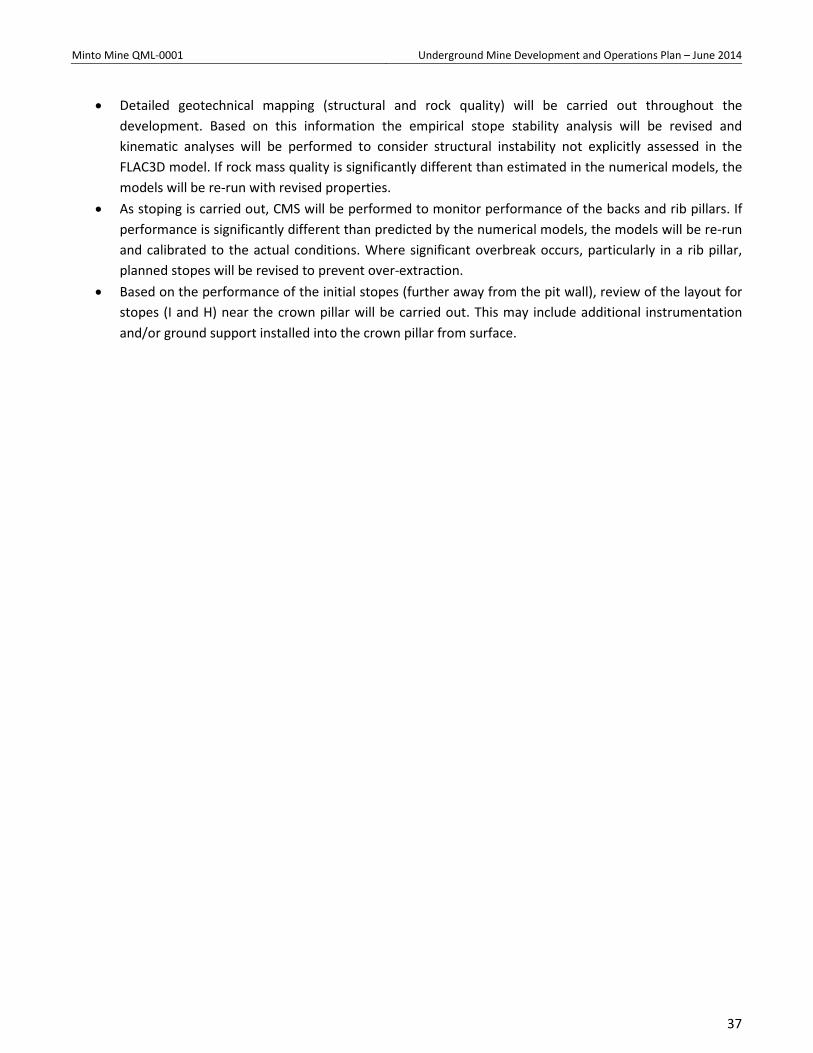
The Minto South Portal ventilation system, designed by Stantec Inc., is a push system with main fans located on surface. Main intake fans provide 132 m³/s (280,000 cfm) through a dedicated 3 m x 5 m intake raise (10 ft. x 16 ft.), which is outfitted with a man-way for egress. Return air is exhausted to surface via the main access ramp. (Refer to the figure below).
Figure 7-1: Minto South Portal ventilation.
A fresh air system consisting on a mine air heating plant and egress manway was driven by Alimak to surface in the 118 Block in January 2014. The Fresh Air Raise consists of one 3 x 5 m limak raise capable of delivering 132 m3/s (280,000 cfm’s) of air. This intake raise was developed on the west side of the Area 2 pit with the raise
38
Minto Mine QML-0001 Underground Mine Development and Operations Plan – June 2014
collar in an area of minimal overburden. It is planned to extend the intake raise down with the main ramp to the Area 2 UG ore zone. Ventilation access drifts will be developed to connect the level development and ramp to the ventilation raises. Those drifts will be 15 m to 40 m long and will be developed at -15% gradients to reduce length of the raise. This system will be capable to meet the future needs of underground mining.
The design basis of the ventilation system at Minto underground operation was to adequately dilute exhaust gases produced by underground diesel equipment. Air volume was calculated on a factor of 0.06 m3/s per installed kW of diesel engine power (100 cfm per installed hp). The kW rating of each piece of underground equipment was determined and then utilization factors, representing the diesel equipment in use at any time, applied to estimate the amount of air required.
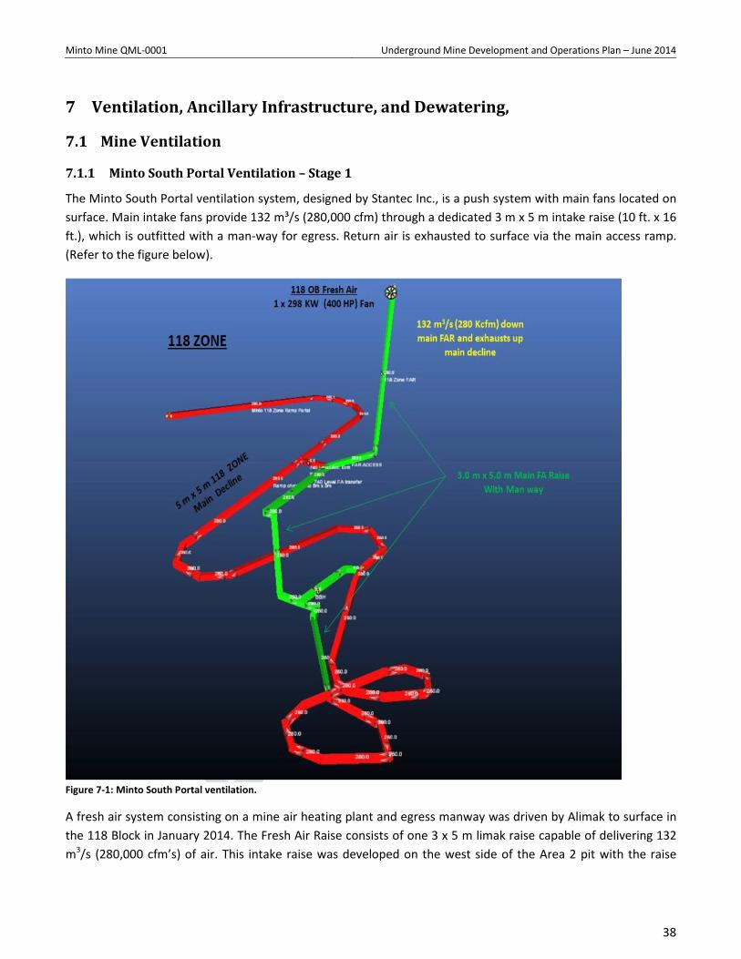
The expected diesel equipment fleet at Minto Mine for the 118 OB at full production is listed in the table below:
Table 7-1: Ventilation requirements Minto South Portal
A maximum of two stoping and one development levels are anticipated during steady state production. The main ramp has been allocated 15 m³/s (32,000 cfm) of fresh air to accommodate the loading and haulage activities of an additional haul truck within the ramp.
Air movement to the stopes would be controlled by directing air flow with ventilation curtains and using the auxiliary ventilation fans. Ventilation regulators, doors, and bulkheads would also be used to control airflow in. As well, signage will be placed at the entrance of headings identifying the equipment allowed in the heading based on the permit cfm’s per piece of equipment.
39
Minto Mine QML-0001 Underground Mine Development and Operations Plan – June 2014
The 150 HP fans are used to provide auxiliary ventilation in other development headings and production stopes.
7.1.2 Commissioning of 118 RA raise to surface and development of Minto East OB access drift – Stage 2
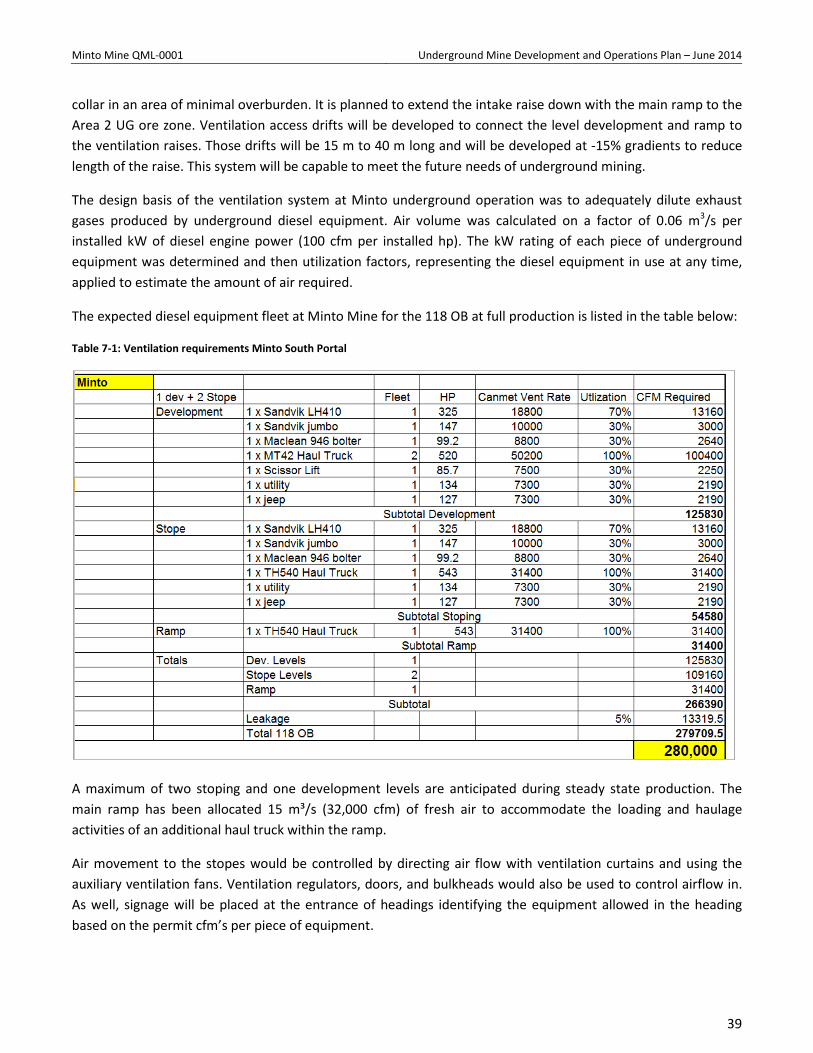
This option allows for the development of the East access drift and occurs upon commissioning of the proposed 118 OB RAR (3.0 m x 3.0 m) to surface. It provides Minto with the capability of blasting at will for the development of the East access and provides sufficient ventilation to complete the production of the 118 OB workings.
Distribution of air will consist of a main fresh air fan and heater on surface providing fresh air to the workings via the 118 OB FA raise. Two runs of auxiliary ducting complete with fans will provide sufficient ventilation for the development of the East access drift. Return air will exhaust both the main ramp out the 118 portal and the 118 OB RAR to surface. Note, the 118 OB RAR will not require any fans.
Figure 7-2: Minto South Portal ventilation - Stage 2
40
Minto Mine QML-0001 Underground Mine Development and Operations Plan – June 2014
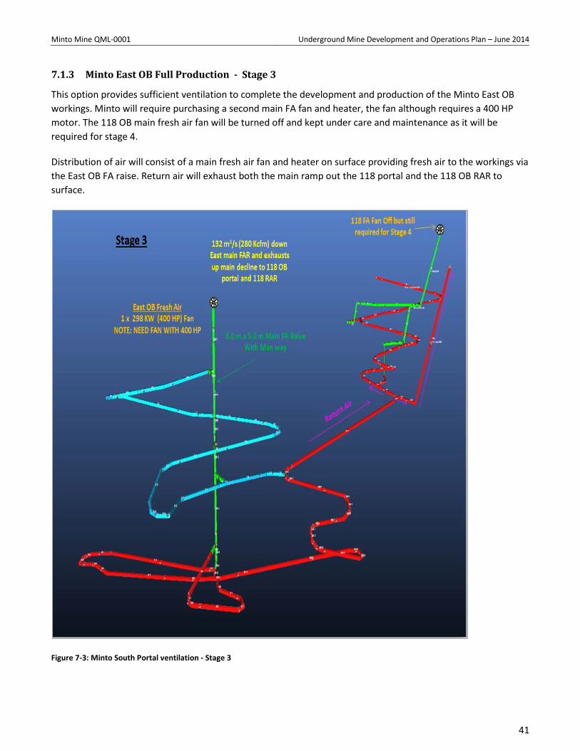
7.1.3 Minto East OB Full Production - Stage 3
This option provides sufficient ventilation to complete the development and production of the Minto East OB workings. Minto will require purchasing a second main FA fan and heater, the fan although requires a 400 HP motor. The 118 OB main fresh air fan will be turned off and kept under care and maintenance as it will be required for stage 4.
Distribution of air will consist of a main fresh air fan and heater on surface providing fresh air to the workings via the East OB FA raise. Return air will exhaust both the main ramp out the 118 portal and the 118 OB RAR to surface.
Figure 7-3: Minto South Portal ventilation - Stage 3
41
Minto Mine QML-0001 Underground Mine Development and Operations Plan – June 2014
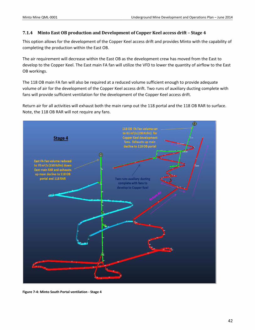
7.1.4 Minto East OB production and Development of Copper Keel access drift – Stage 4
This option allows for the development of the Copper Keel access drift and provides Minto with the capability of completing the production within the East OB.
The air requirement will decrease within the East OB as the development crew has moved from the East to develop to the Copper Keel. The East main FA fan will utilize the VFD to lower the quantity of airflow to the East OB workings.
The 118 OB main FA fan will also be required at a reduced volume sufficient enough to provide adequate volume of air for the development of the Copper Keel access drift. Two runs of auxiliary ducting complete with fans will provide sufficient ventilation for the development of the Copper Keel access drift.
Return air for all activities will exhaust both the main ramp out the 118 portal and the 118 OB RAR to surface. Note, the 118 OB RAR will not require any fans.
Figure 7-4: Minto South Portal ventilation - Stage 4
42
Minto Mine QML-0001 Underground Mine Development and Operations Plan – June 2014
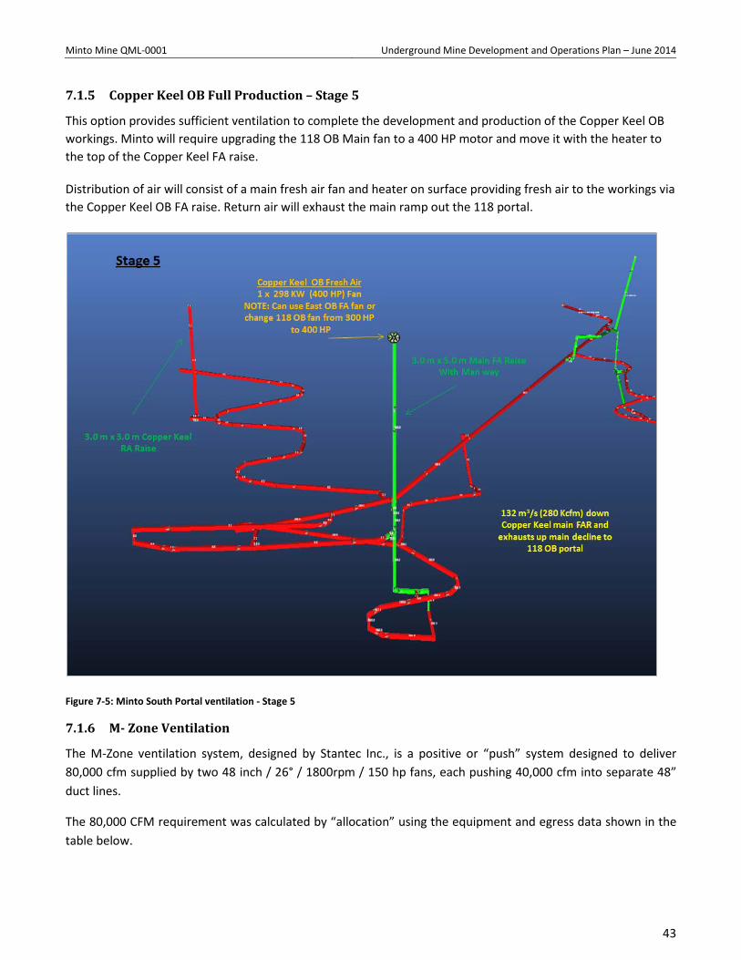
7.1.5 Copper Keel OB Full Production – Stage 5
This option provides sufficient ventilation to complete the development and production of the Copper Keel OB workings. Minto will require upgrading the 118 OB Main fan to a 400 HP motor and move it with the heater to the top of the Copper Keel FA raise.
Distribution of air will consist of a main fresh air fan and heater on surface providing fresh air to the workings via the Copper Keel OB FA raise. Return air will exhaust the main ramp out the 118 portal.
Figure 7-5: Minto South Portal ventilation - Stage 5
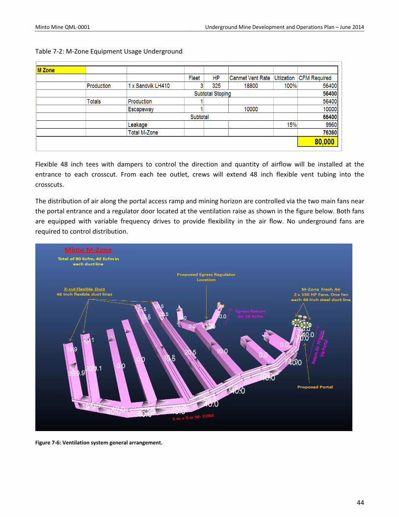
7.1.6 M- Zone Ventilation
The M-Zone ventilation system, designed by Stantec Inc., is a positive or “push” system designed to deliver 80,000 cfm supplied by two 48 inch / 26° / 1800rpm / 150 hp fans, each pushing 40,000 cfm into separate 48” duct lines.
The 80,000 CFM requirement was calculated by “allocation” using the equipment and egress data shown in the table below.
43
Minto Mine QML-0001 Underground Mine Development and Operations Plan – June 2014
Table 7-2: M-Zone Equipment Usage Underground
Flexible 48 inch tees with dampers to control the direction and quantity of airflow will be installed at the entrance to each crosscut. From each tee outlet, crews will extend 48 inch flexible vent tubing into the crosscuts.
The distribution of air along the portal access ramp and mining horizon are controlled via the two main fans near the portal entrance and a regulator door located at the ventilation raise as shown in the figure below. Both fans are equipped with variable frequency drives to provide flexibility in the air flow. No underground fans are required to control distribution.
Figure 7-6: Ventilation system general arrangement.
44
Minto Mine QML-0001 Underground Mine Development and Operations Plan – June 2014
7.2 Mine Air Heating
7.2.1 Minto South Portal Air Heating
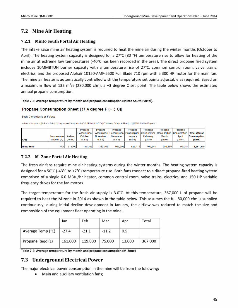
The intake raise mine air heating system is required to heat the mine air during the winter months (October to April). The heating system capacity is designed for a 27°C (80 °F) temperature rise to allow for heating of the mine air at extreme low temperatures (-40°C has been recorded in the area). The direct propane fired system includes 10MMBTUH burner capacity with a temperature rise of 27°C, common control room, valve trains, electrics, and the proposed Alphair 10150-AMF-5500 Full Blade 710 rpm with a 300 HP motor for the main fan. The mine air heater is automatically controlled with the temperature set points adjustable as required. Based on a maximum flow of 132 m3/s (280,000 cfm), a +3 degree C set point. The table below shows the estimated annual propane consumption.
Table 7-3: Average temperature by month and propane consumption (Minto South Portal).
7.2.2 M- Zone Portal Air Heating
The fresh air fans require mine air heating systems during the winter months. The heating system capacity is designed for a 50°C (-43°C to +7°C) temperature rise. Both fans connect to a direct propane-fired heating system comprised of a single 6.0 MBtu/hr heater, common control room, valve trains, electrics, and 150 HP variable frequency drives for the fan motors.
The target temperature for the fresh air supply is 3.0°C. At this temperature, 367,000 L of propane will be required to heat the M-zone in 2014 as shown in the table below. This assumes the full 80,000 cfm is supplied continuously; during initial decline development in January, the airflow was reduced to match the size and composition of the equipment fleet operating in the mine.
Jan Feb Mar Apr Total
Average Temp (°C) -27.4 -21.1 -11.2 0.5
Propane Reqd (L) 161,000 119,000 75,000 13,000 367,000
Table 7-4: Average temperature by month and propane consumption (M-Zone)
7.3 Underground Electrical Power The major electrical power consumption in the mine will be from the following:
• Main and auxiliary ventilation fans;
45
Minto Mine QML-0001 Underground Mine Development and Operations Plan – June 2014
• Drilling equipment; • Mine dewatering pumps; • Air compressors; and • Maintenance shop
7.3.1 Minto South portal Electrical Power
High voltage cable (4160V) enters the mine via the decline and is distributed to electrical sub-stations located just below the portal collar. The power cables are suspended from the back of development headings. All equipment and cables are protected to prevent electrical hazards to personnel.
High voltage power is delivered at 4.16 kV and reduced to 600 V at electrical sub-stations. All power is three-phase. Lighting and convenience receptacles are single phase 120 V power.
7.3.2 M- Zone Electrical Power
The M-zone underground will be supplied with power by a connection to Minto’s power grid, which currently extends to the edge of the Area 2 pit.
Approximately 550m of 5kV Teck 2/0 cable will be run down the pit wall. From 811 to 788 m elevation, the cable will be placed along the overburden cut at the east corner of the pit, which is sloped at 30°. The cable will then drop down to the portal elevation (691m) via four drops of 18 to 24m along the bench faces of the pit highwall. The cable will cross the haul ramp twice through two lengths of buried 4” HDPE pipe at each crossing.
One of the two transformers used in the 118 zone underground rated at 750kVA will be installed at the south end of the pit, 95m from the portal.
7.4 Compressed Air Minto currently has the following compressors:
• Two 350 CFM electrics (one M – Zone and one Minto South Portal) • One 1000 CFM electric (M – Zone, move to Minto South upon completion of M-zone) • One 750 CFM diesel
The electric compressors are used to supply air underground, while the diesel supplies surface air as required. Portable electric compressors provide compressed air requirements on an as-needed basis.
The underground mobile drilling equipment such as jumbos, rockbolters and Emulsion / ANFO loaders are equipped with their own compressors. No reticulated compressed air system was envisioned to be required underground.
The electric compressors are utilized to satisfy compressed air consumption for miscellaneous underground operations, such as: jackleg and stoper drilling, Alimak raise development and pumping with pneumatic pumps.
46
Minto Mine QML-0001 Underground Mine Development and Operations Plan – June 2014
7.5 Dewatering and Effluent Treatment
7.5.1 Water Supply
The major drilling equipment such as jumbos, rockbolters and exploration drills use run-of-mine water obtained from the active pit area, or from underground inflows into sumps. Currently, at the Minto South Portal, the supply water is placed into a 45,000 liter (10,000gal) heated storage tank just outside the portal. At approximately 125 meters down the ramp from the portal collar. Water is currently trucked to the 45,000 liter tank and is piped to the 227,000 liter (50,000 Gal) supply water storage drift.
7.5.2 Minto South Portal Dewatering
A permanent discharge water line is established from Minto South Portal to the site water management system. During development or production, discharge water is pumped to a surface and then transported through discharge water line into to the main pit. Once water has been moved to the Main Pit (and/or Area 2 pit according to the water/tailings management plan), it will be subject to treatment with the existing onsite facilities.
47
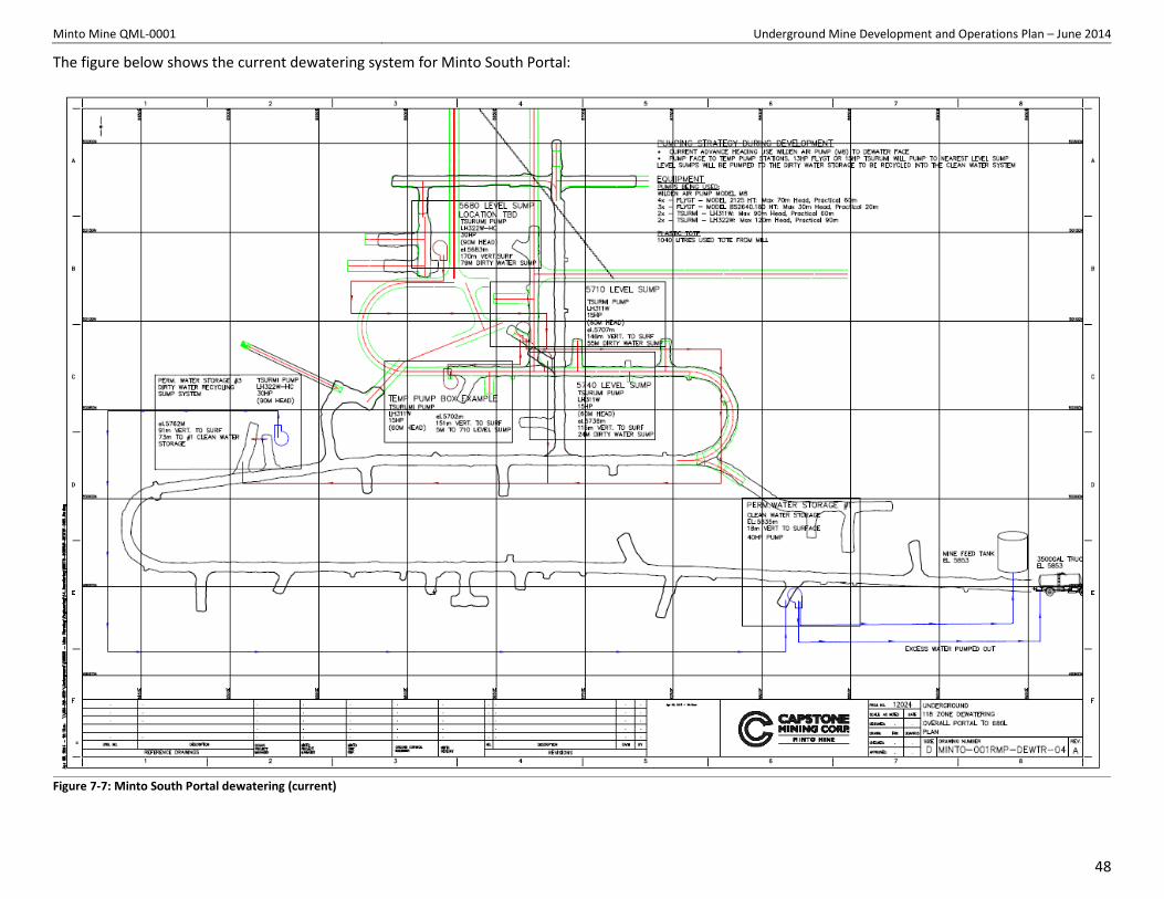
Minto Mine QML-0001 Underground Mine Development and Operations Plan – June 2014
The figure below shows the current dewatering system for Minto South Portal:
Figure 7-7: Minto South Portal dewatering (current)
48
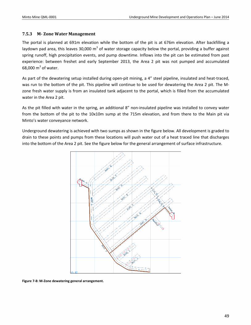
Minto Mine QML-0001 Underground Mine Development and Operations Plan – June 2014
7.5.3 M- Zone Water Management
The portal is planned at 691m elevation while the bottom of the pit is at 676m elevation. After backfilling a laydown pad area, this leaves 30,000 m3 of water storage capacity below the portal, providing a buffer against spring runoff, high precipitation events, and pump downtime. Inflows into the pit can be estimated from past experience: between freshet and early September 2013, the Area 2 pit was not pumped and accumulated 68,000 m3 of water.
As part of the dewatering setup installed during open-pit mining, a 4” steel pipeline, insulated and heat-traced, was run to the bottom of the pit. This pipeline will continue to be used for dewatering the Area 2 pit. The M-zone fresh water supply is from an insulated tank adjacent to the portal, which is filled from the accumulated water in the Area 2 pit.
As the pit filled with water in the spring, an additional 8” non-insulated pipeline was installed to convey water from the bottom of the pit to the 10x10m sump at the 715m elevation, and from there to the Main pit via Minto’s water conveyance network.
Underground dewatering is achieved with two sumps as shown in the figure below. All development is graded to drain to these points and pumps from these locations will push water out of a heat traced line that discharges into the bottom of the Area 2 pit. See the figure below for the general arrangement of surface infrastructure.
Figure 7-8: M-Zone dewatering general arrangement.
49
Minto Mine QML-0001 Underground Mine Development and Operations Plan – June 2014
7.5.4 Mine Water Quality and Inflow Monitoring
The Water Use Licence QZ96-006 – Amendment 8 (WUL) outlines the monitoring and surveillance of the underground at Minto. W44 has been assigned as a station number and monitoring frequency as part of the licence for the Minto South portal access. A representative sample of underground inflows will be taken regularly, and flows will be monitored. The water pumped from the m-zone is considered to be Area 2 pit water and the sample station number is W45. Results of the monitoring work will be presented in the monthly WUL reports and summarised in the QML and WUL annual report.
7.6 Communications A fiber optic communication system will be used as the communication system for mine and surface operations. The system will be a radio over IP and will provide communications, personal tagging and tracking as well as critical equipment control. Underground personnel (such as mobile mechanics, crew leaders, and shift bosses) and mobile equipment operators (such as loader, truck, and utility vehicle operators) will be supplied with an underground radio for contact with the fiber optics network.
7.7 Explosive Storage and Handling Explosives are stored on surface in permanent magazines; detonation supplies (NONEL, electrical caps, detonating cords, etc.) are stored in a separate magazine.
Underground powder and cap magazines are prepared in Minto South Portal.
Anfo is used as the major explosive for mine development and production. Packaged emulsion is used as a primer and for loading lifter holes in the development headings. Smooth blasting techniques are used as required main access development headings.
All personnel underground would be required to be in a designated Safe Work Area during blasting. During production period, a central blast system would be used to initiate blasts for all loaded development headings and production stopes at the end of the shift. Safe work procedures that are currently being used at the mine are presented in Appendix C. Safe work procedures will be revised as required by the conditions in the mine.
7.8 Fuel Storage and Distribution An average fuel consumption rate of approximately 5,000 l/d is estimated for the period of full production.
Haulage trucks, LHDs, and all auxiliary vehicles are fuelled at fuel stations on surface. An auxiliary tank used for the fuelling/lubing of drills and rock bolters. A 50,000 liter EnviroTank is installed on surface (Pad# 1).
All underground personnel are trained in site wide spill prevention and spill response protocols outlined in Minto Mine’s Spill Contingency Plan.
50
Minto Mine QML-0001 Underground Mine Development and Operations Plan – June 2014
8 Mine safety
8.1 General Mine Safety Minto Mine and the development contractor emphasize safety in all duties at the mine; this philosophy is shared by and with senior management, on site supervisors and daily operators.
This project will be undertaken with a dedicated focus on “Zero Harm”. All non-routine tasks will be assessed for risk to ensure suitable control measures are in place.
All work will be performed within the strict guidelines of both Minto’s and Contractor’s safety programs. Both programs will comply with all required internal policies and procedures, as well as the Yukon Territory’s legislated requirements.
The Contractor will utilize its Safety and Training Program, which includes risk assessments, job observations, workplace inspections and regular program audits. Any new work which is non-routine will be subjected to a full risk assessment which would then be used to develop new site specific work procedures. The Contractor will maintain detailed training records of every employee, both on-site and at their main office.
A key component of the Contractor’s commitment to “Zero Harm” is the use of the Zero Harm Safety System and associated safety card in the field, which is consistent with current on-site practices.
All safety concerns are documented, assigned responsibility, and tracked until rectified.
8.2 Emergency Response Initially, when the working face is within 500 meters of the portal, emergency escape will be directly to the surface via the portal this is valid for Minto South and M-Zone. An Emergency Cache is located near the working face consisting of 6 – EBA 6.5 breathing apparatus, first aid supplies, Oxygen therapy unit, water, food, flashlights and blankets. Once the decline reaches 500 meters in length from the portal to the working face, a portable refuge station will be installed underground near the face. Portable refuge stations are maintained in locations of mine development to include refuge < 15 minute travel time by foot. All underground personnel will follow fresh air and escape to surface or take refuge in a refuge station during all emergencies that affect the underground. Refuge station posted “code of conduct” must be followed by everyone in the refuge station.The portable refuge stations are designed to be equipped with compressed air/oxygen cylinders, potable water, and first aid equipment; they will also be supplied with a fixed telephone line and emergency lighting. During the initial development phase, one refuge station, capable of 72 hours and 15 men is utilized. As manpower and distance increase a second portable refuge station will be sourced. The portable refuge chambers will be moved to the new locations as the working areas advance, eliminating the need to construct permanent refuge stations.
Fire extinguishers will be provided and maintained in accordance with regulations and best practices at the underground electrical installations, pump stations and other strategic areas. Every vehicle will carry at least one fire extinguisher of adequate size and proper type. Underground heavy equipment will be equipped with automatic fire suppression systems.
51
Minto Mine QML-0001 Underground Mine Development and Operations Plan – June 2014
All underground personnel will be required to carry Ocenco M-20 self-contained self-rescuer (SCSR) devices. The Ocenco M-20- SCSR isolates the user’s lungs from the surrounding atmosphere and utilizes compressed oxygen to provide respiratory protection. The M-20’s will provide 15 – 20 minutes of Performance duration and 32 minutes of Rest duration. In addition to the personal devices, six devices with longer performance durations of 60 minutes will also be supplied and kept near the ramp face during development; personal CO detectors will be made available to the development crews.
Fire extinguishers will be provided and maintained in accordance with regulations and best practices at the underground electrical installations, pump stations, fuelling stations, and other strategic areas. Every vehicle will carry at least one fire extinguisher of adequate size and proper type. Underground heavy equipment will be equipped with automatic fire suppression systems.
A mine-wide stench gas warning system is installed at the main intake raise to alert underground workers in the event of an emergency. During the initial development phase; prior to completion of the main fresh air raise, stench gas warning will be in the temporary fresh air system.
The main access decline would provide primary access and the ventilation raises with dedicated manway would be equipped with ladders and platforms providing the secondary exit in case of emergency. This secondary egress was completed in January 2014.
The Emergency Response Team that is currently at Minto has both Surface and Underground competent responders working in coordination with defined mine rescue certified members and UG specialists within the contractor ranks.
Further information on mine safety for the underground mine is provided in the Emergency Response Plan in Appendix D.
8.3 Hours of Work Minto requested and received an hours of work variance (presented in Appendix E), specific to the first 4,500 meters of ramp development and associated ore removal.
The requested hours of work variance for these 4,500 meters of underground development included: • 11 hours per shift of underground exposure for workers in enclosed cabs of mobile equipment. • 10.5 hours per shift of underground exposure for all other employees. • Shift rotation of 3 weeks on and 3 weeks off for the contractor’s staff employees. • Shift rotation of 4 weeks on and 2 weeks off for the contractor’s hourly rated employees.
8.4 Industrial Hygiene and Fatigue Management Programs An industrial hygiene (IH) consultant was engaged to assist Minto in the development of an underground IH plan and a fatigue risk management programs (acceptable to YWCHSB) for, but not limited to, air quality, noise and fatigue. The consultant will be involved throughout the development to conduct regular review of the program and testing results. The purpose of this plan is to develop process and procedures to ensure the highest possible air quality is maintained, (TLV levels), manage noise and to develop and implement a Fatigue Management
52
Minto Mine QML-0001 Underground Mine Development and Operations Plan – June 2014
Program. The Fatigue Management Plan has been presented in Appendix G. The IH consultant will also be utilized in the definition and calculation of adjusted TLV values.
Until such times that the IH data confirms that air quality exposure is below the adjusted TLV concentrations, respirators will be a mandatory piece of PPE equipment to all employees entering the underground workings.
The plan is that that prior to the completion of the 4500 meters of development to apply for a permanent variance to the hours of work. The IH data and programs for air quality, noise and fatigue will form the bases of this request.
8.5 Hours of Underground Exposure Monitoring In order to ensure compliance with the requested hours of underground exposure, Minto Mine will utilize Smart Tags. Smart Tags are long range RFID (Radio Frequency Identification) to track employee’s underground exposure hours in real time. This system consists of an active RFID tag located on the employee, whether it is on their hard hat, safety belt pouch or inside the cap lamp; and a networked RFID reader located at the portal collar. Data is then sent to a central computer system which facilitates system control and monitoring though the Smart Tag software (or similar) in real time by employee.
8.6 First Line Supervisory Training The Contractor will comply with the Yukon Occupational Health and Safety (OH&S) regulation by obtaining First Line Supervisor’s Provisional Certificates and working toward full certification during the development.
Safety considerations in Underground Equipment / Materials
8.6.1 Diesel Equipment
All diesel equipment used in the underground operation will be permitted and maintained to comply with section 15.58, 15.59, 15.61 and all related sections on the Yukon Occupational Health and Safety Regulation.
8.6.2 Portable Compressors
The current plan calls for electric compressors underground, however, if the diesel is required, it will be equipped with the necessary fire suppression, CO monitor and shut off requirements.
8.6.3 Shotcrete
Shotcrete used in the underground workings will be restricted to “wet system” process only; this will eliminate the cement dust particulate associated with dry shotcrete application.
8.7 WCHSB Reporting Quarterly update meetings are scheduled to be held with YWCSHB to review the following:
• IH Program data and Fatigue Management Plan progress • Updated Mining Plan
The dates of the Quarterly Update Meeting should be set annually, with some latitude for mutually acceptable alternative dates.
53
Minto Mine QML-0001 Underground Mine Development and Operations Plan – June 2014
Any variances to defined engineering or administrative controls put in place and defined by the IH program will be reported to YWCHSB as soon as reasonable along with corrective actions that Minto will take toward elimination of further variances.
All aspects of the current surface health and safety program and compliment of Safety personnel in place at the Minto Mine will be extended to the underground operations during the initial development in cooperation with the contractor as we are considering this an additional department of our operation.
JOHSC worker representation will be extended to underground operations and will expand in conjunction with the size of the workforce associated to the underground operation
.
54
Minto Mine QML-0001 Underground Mine Development and Operations Plan – June 2014
9 Conclusion This Underground Mine Development and Operations Plan incorporated the requirements outlined by the Quartz Mining Licence. Minto recognizes that some changes to the mine plan and methods are likely as development and operations continue and more is learned about underground activities at the site. This plan will be updated as necessary to reflect newly acquired information and knowledge obtained from ongoing operations.
55
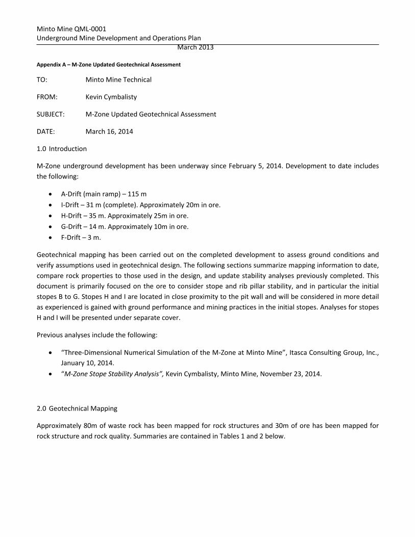
Minto Mine QML-0001 Underground Mine Development and Operations Plan March 2013 Appendix A – M-Zone Updated Geotechnical Assessment
TO: Minto Mine Technical
FROM: Kevin Cymbalisty
SUBJECT: M-Zone Updated Geotechnical Assessment
DATE: March 16, 2014
1.0 Introduction
M-Zone underground development has been underway since February 5, 2014. Development to date includes the following:
• A-Drift (main ramp) – 115 m • I-Drift – 31 m (complete). Approximately 20m in ore. • H-Drift – 35 m. Approximately 25m in ore. • G-Drift – 14 m. Approximately 10m in ore. • F-Drift – 3 m.
Geotechnical mapping has been carried out on the completed development to assess ground conditions and verify assumptions used in geotechnical design. The following sections summarize mapping information to date, compare rock properties to those used in the design, and update stability analyses previously completed. This document is primarily focused on the ore to consider stope and rib pillar stability, and in particular the initial stopes B to G. Stopes H and I are located in close proximity to the pit wall and will be considered in more detail as experienced is gained with ground performance and mining practices in the initial stopes. Analyses for stopes H and I will be presented under separate cover.
Previous analyses include the following:
• “Three-Dimensional Numerical Simulation of the M-Zone at Minto Mine”, Itasca Consulting Group, Inc., January 10, 2014.
• “M-Zone Stope Stability Analysis”, Kevin Cymbalisty, Minto Mine, November 23, 2014.
2.0 Geotechnical Mapping
Approximately 80m of waste rock has been mapped for rock structures and 30m of ore has been mapped for rock structure and rock quality. Summaries are contained in Tables 1 and 2 below.
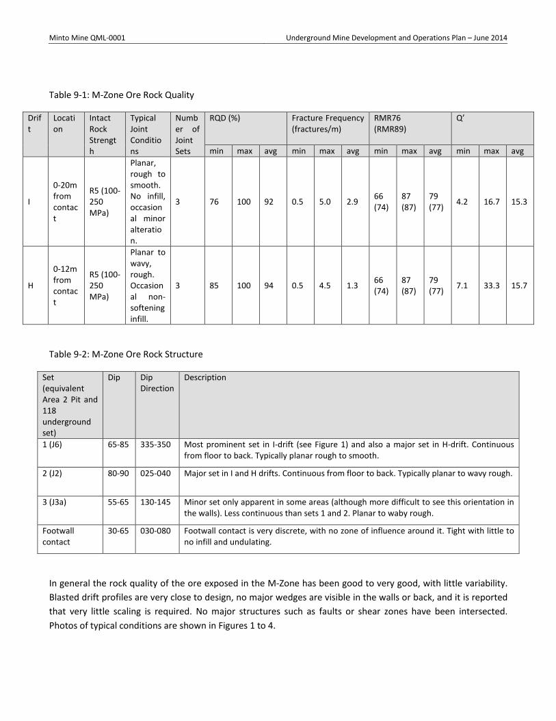
Minto Mine QML-0001 Underground Mine Development and Operations Plan – June 2014
Table 9-1: M-Zone Ore Rock Quality
Drift
Location
Intact Rock Strength
Typical Joint Conditions
Number of Joint Sets
RQD (%) Fracture Frequency (fractures/m)
RMR76 (RMR89)
Q’
min max avg min max avg min max avg min max avg
I
0-20m from contact
R5 (100-250 MPa)
Planar, rough to smooth. No infill, occasional minor alteration.
3 76 100 92 0.5 5.0 2.9 66 (74)
87 (87)
79 (77) 4.2 16.7 15.3
H
0-12m from contact
R5 (100-250 MPa)
Planar to wavy, rough. Occasional non-softening infill.
3 85 100 94 0.5 4.5 1.3 66 (74)
87 (87)
79 (77) 7.1 33.3 15.7
Table 9-2: M-Zone Ore Rock Structure
Set (equivalent Area 2 Pit and 118 underground set)
Dip Dip Direction
Description
1 (J6) 65-85 335-350 Most prominent set in I-drift (see Figure 1) and also a major set in H-drift. Continuous from floor to back. Typically planar rough to smooth.
2 (J2) 80-90 025-040 Major set in I and H drifts. Continuous from floor to back. Typically planar to wavy rough.
3 (J3a) 55-65 130-145 Minor set only apparent in some areas (although more difficult to see this orientation in the walls). Less continuous than sets 1 and 2. Planar to waby rough.
Footwall contact
30-65 030-080 Footwall contact is very discrete, with no zone of influence around it. Tight with little to no infill and undulating.
In general the rock quality of the ore exposed in the M-Zone has been good to very good, with little variability. Blasted drift profiles are very close to design, no major wedges are visible in the walls or back, and it is reported that very little scaling is required. No major structures such as faults or shear zones have been intersected. Photos of typical conditions are shown in Figures 1 to 4.
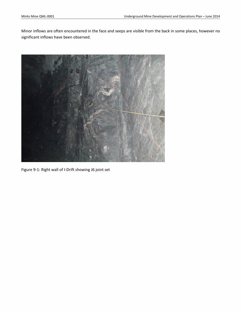
Minto Mine QML-0001 Underground Mine Development and Operations Plan – June 2014
Minor inflows are often encountered in the face and seeps are visible from the back in some places, however no significant inflows have been observed.
Figure 9-1: Right wall of I-Drift showing J6 joint set
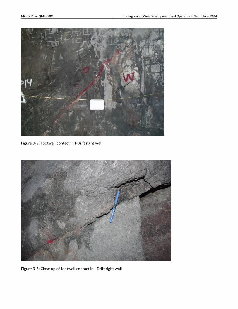
Minto Mine QML-0001 Underground Mine Development and Operations Plan – June 2014
Figure 9-2: Footwall contact in I-Drift right wall
Figure 9-3: Close up of footwall contact in I-Drift right wall
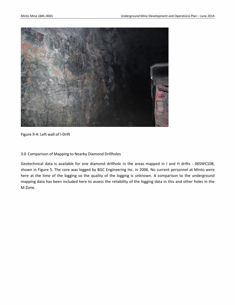
Minto Mine QML-0001 Underground Mine Development and Operations Plan – June 2014
Figure 9-4: Left wall of I-Drift
3.0 Comparison of Mapping to Nearby Diamond Drillholes
Geotechnical data is available for one diamond drillhole in the areas mapped in I and H drifts - 06SWC108, shown in Figure 5. The core was logged by BGC Engineering Inc. in 2006. No current personnel at Minto were here at the time of the logging so the quality of the logging is unknown. A comparison to the underground mapping data has been included here to assess the reliability of the logging data in this and other holes in the M-Zone.
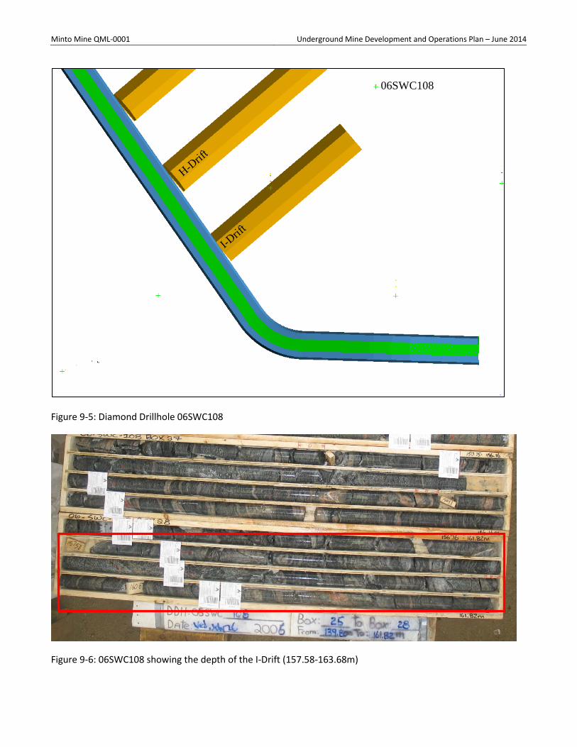
Minto Mine QML-0001 Underground Mine Development and Operations Plan – June 2014
Figure 9-5: Diamond Drillhole 06SWC108
Figure 9-6: 06SWC108 showing the depth of the I-Drift (157.58-163.68m)
06SWC108
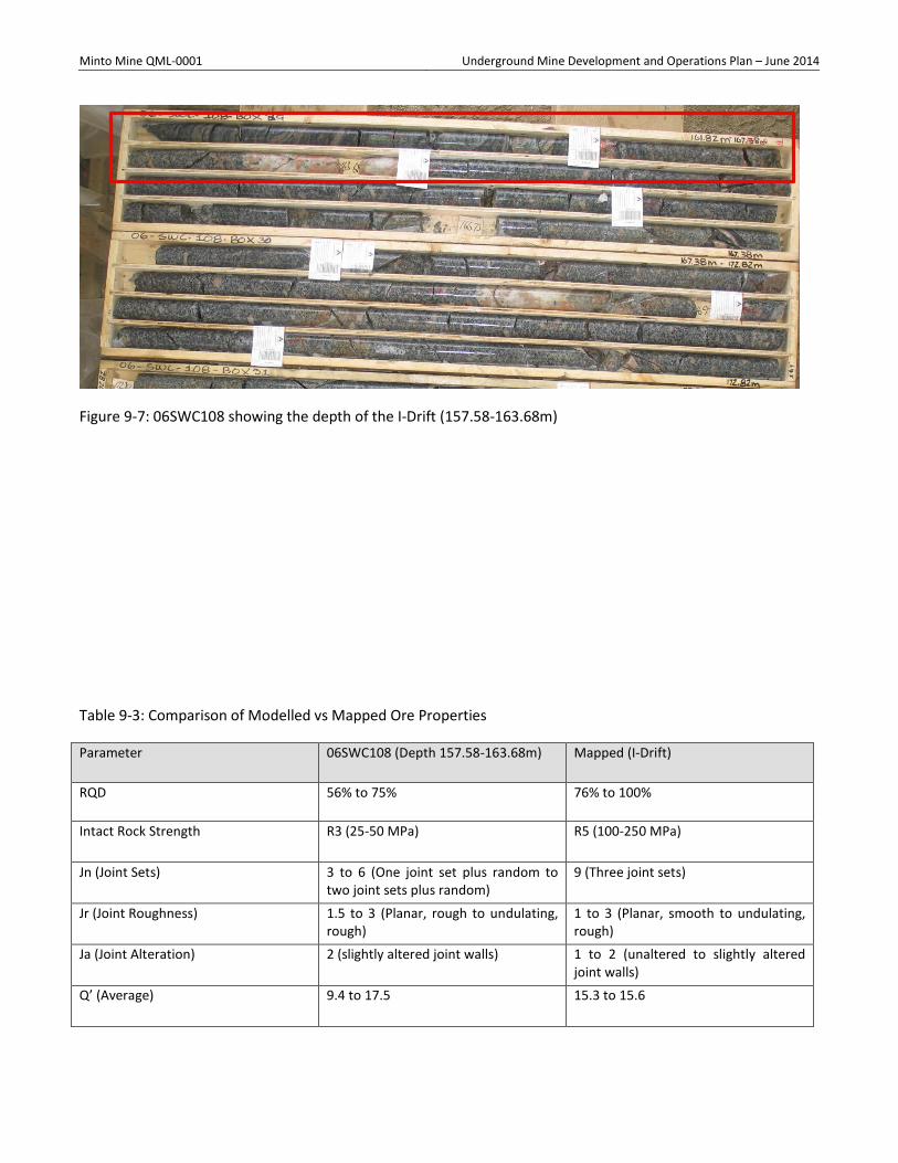
Minto Mine QML-0001 Underground Mine Development and Operations Plan – June 2014
Figure 9-7: 06SWC108 showing the depth of the I-Drift (157.58-163.68m)
Table 9-3: Comparison of Modelled vs Mapped Ore Properties
Parameter 06SWC108 (Depth 157.58-163.68m) Mapped (I-Drift)
RQD 56% to 75% 76% to 100%
Intact Rock Strength R3 (25-50 MPa) R5 (100-250 MPa)
Jn (Joint Sets) 3 to 6 (One joint set plus random to two joint sets plus random)
9 (Three joint sets)
Jr (Joint Roughness) 1.5 to 3 (Planar, rough to undulating, rough)
1 to 3 (Planar, smooth to undulating, rough)
Ja (Joint Alteration) 2 (slightly altered joint walls) 1 to 2 (unaltered to slightly altered joint walls)
Q’ (Average) 9.4 to 17.5 15.3 to 15.6
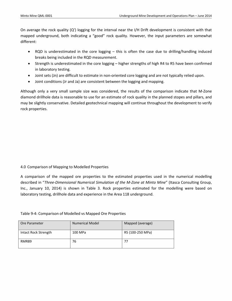
Minto Mine QML-0001 Underground Mine Development and Operations Plan – June 2014
On average the rock quality (Q’) logging for the interval near the I/H Drift development is consistent with that mapped underground, both indicating a “good” rock quality. However, the input parameters are somewhat different:
• RQD is underestimated in the core logging – this is often the case due to drilling/handling induced breaks being included in the RQD measurement.
• Strength is underestimated in the core logging – higher strengths of high R4 to R5 have been confirmed in laboratory testing.
• Joint sets (Jn) are difficult to estimate in non-oriented core logging and are not typically relied upon. • Joint conditions (Jr and Ja) are consistent between the logging and mapping.
Although only a very small sample size was considered, the results of the comparison indicate that M-Zone diamond drillhole data is reasonable to use for an estimate of rock quality in the planned stopes and pillars, and may be slightly conservative. Detailed geotechnical mapping will continue throughout the development to verify rock properties.
4.0 Comparison of Mapping to Modelled Properties
A comparison of the mapped ore properties to the estimated properties used in the numerical modelling described in “Three-Dimensional Numerical Simulation of the M-Zone at Minto Mine” (Itasca Consulting Group, Inc., January 10, 2014) is shown in Table 3. Rock properties estimated for the modelling were based on laboratory testing, drillhole data and experience in the Area 118 underground.
Table 9-4: Comparison of Modelled vs Mapped Ore Properties
Ore Parameter Numerical Model Mapped (average)
Intact Rock Strength 100 MPa R5 (100-250 MPa)
RMR89 76 77

Minto Mine QML-0001 Underground Mine Development and Operations Plan – June 2014
The rock properties used in the numerical models are nearly identical to those mapped on average in the M-Zone ore thus far. As such, it is unlikely that an update to the model will be required; however, mapping and verification will be continued throughout the remaining development.
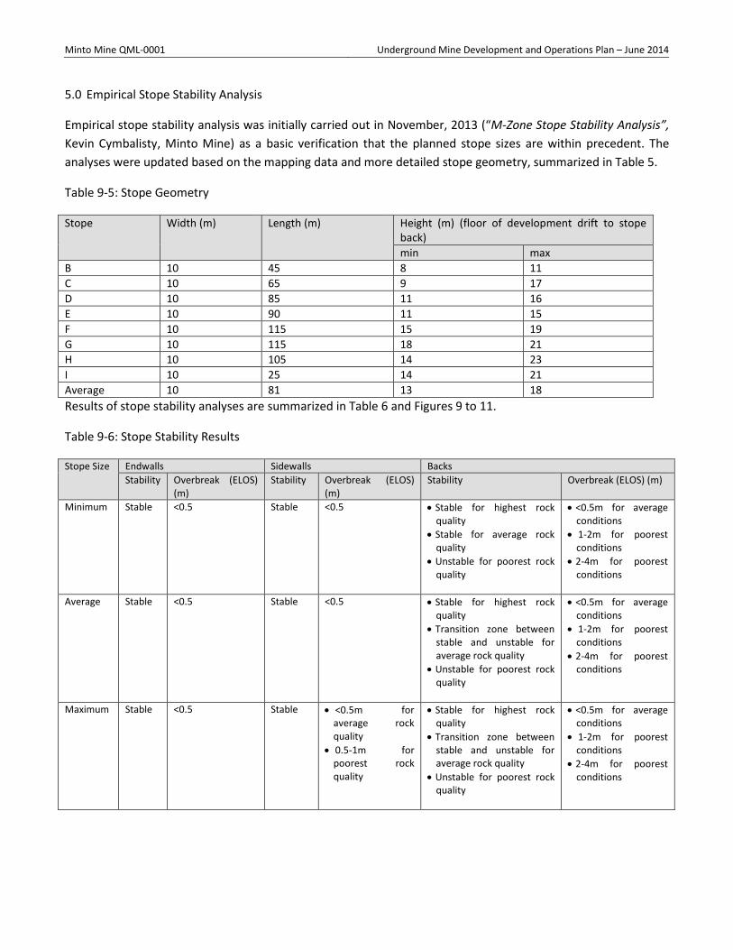
Minto Mine QML-0001 Underground Mine Development and Operations Plan – June 2014
5.0 Empirical Stope Stability Analysis
Empirical stope stability analysis was initially carried out in November, 2013 (“M-Zone Stope Stability Analysis”, Kevin Cymbalisty, Minto Mine) as a basic verification that the planned stope sizes are within precedent. The analyses were updated based on the mapping data and more detailed stope geometry, summarized in Table 5.
Table 9-5: Stope Geometry
Stope Width (m) Length (m) Height (m) (floor of development drift to stope back) min max
B 10 45 8 11 C 10 65 9 17 D 10 85 11 16 E 10 90 11 15 F 10 115 15 19 G 10 115 18 21 H 10 105 14 23 I 10 25 14 21 Average 10 81 13 18 Results of stope stability analyses are summarized in Table 6 and Figures 9 to 11.
Table 9-6: Stope Stability Results
Stope Size Endwalls Sidewalls Backs Stability Overbreak (ELOS)
(m) Stability Overbreak (ELOS)
(m) Stability Overbreak (ELOS) (m)
Minimum Stable <0.5 Stable <0.5 • Stable for highest rock quality
• Stable for average rock quality
• Unstable for poorest rock quality
• <0.5m for average conditions
• 1-2m for poorest conditions
• 2-4m for poorest conditions
Average Stable <0.5 Stable <0.5 • Stable for highest rock quality
• Transition zone between stable and unstable for average rock quality
• Unstable for poorest rock quality
• <0.5m for average conditions
• 1-2m for poorest conditions
• 2-4m for poorest conditions
Maximum Stable <0.5 Stable • <0.5m for average rock quality
• 0.5-1m for poorest rock quality
• Stable for highest rock quality
• Transition zone between stable and unstable for average rock quality
• Unstable for poorest rock quality
• <0.5m for average conditions
• 1-2m for poorest conditions
• 2-4m for poorest conditions
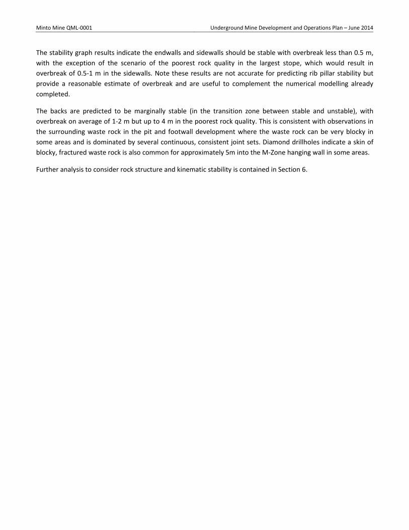
Minto Mine QML-0001 Underground Mine Development and Operations Plan – June 2014
The stability graph results indicate the endwalls and sidewalls should be stable with overbreak less than 0.5 m, with the exception of the scenario of the poorest rock quality in the largest stope, which would result in overbreak of 0.5-1 m in the sidewalls. Note these results are not accurate for predicting rib pillar stability but provide a reasonable estimate of overbreak and are useful to complement the numerical modelling already completed.
The backs are predicted to be marginally stable (in the transition zone between stable and unstable), with overbreak on average of 1-2 m but up to 4 m in the poorest rock quality. This is consistent with observations in the surrounding waste rock in the pit and footwall development where the waste rock can be very blocky in some areas and is dominated by several continuous, consistent joint sets. Diamond drillholes indicate a skin of blocky, fractured waste rock is also common for approximately 5m into the M-Zone hanging wall in some areas.
Further analysis to consider rock structure and kinematic stability is contained in Section 6.
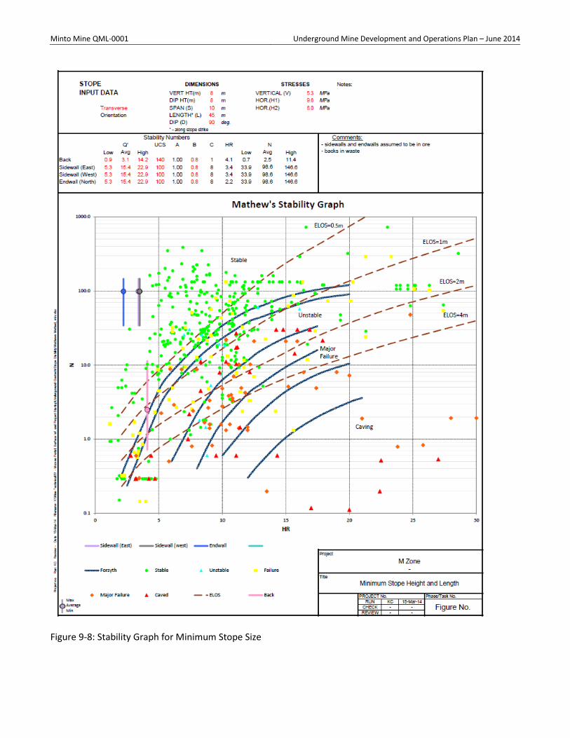
Minto Mine QML-0001 Underground Mine Development and Operations Plan – June 2014
Figure 9-8: Stability Graph for Minimum Stope Size
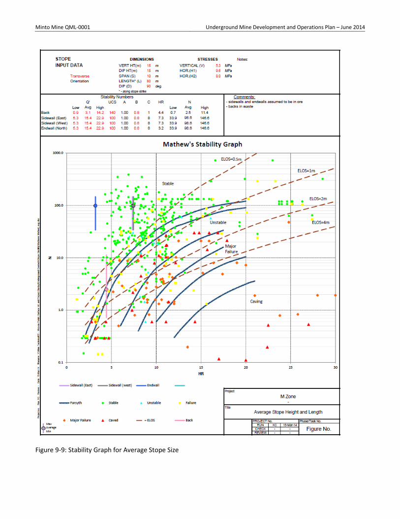
Minto Mine QML-0001 Underground Mine Development and Operations Plan – June 2014
Figure 9-9: Stability Graph for Average Stope Size
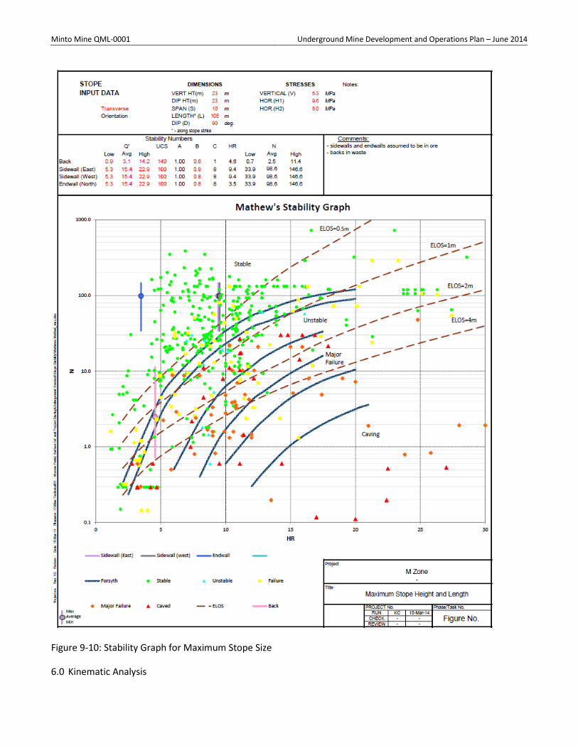
Minto Mine QML-0001 Underground Mine Development and Operations Plan – June 2014
Figure 9-10: Stability Graph for Maximum Stope Size
6.0 Kinematic Analysis
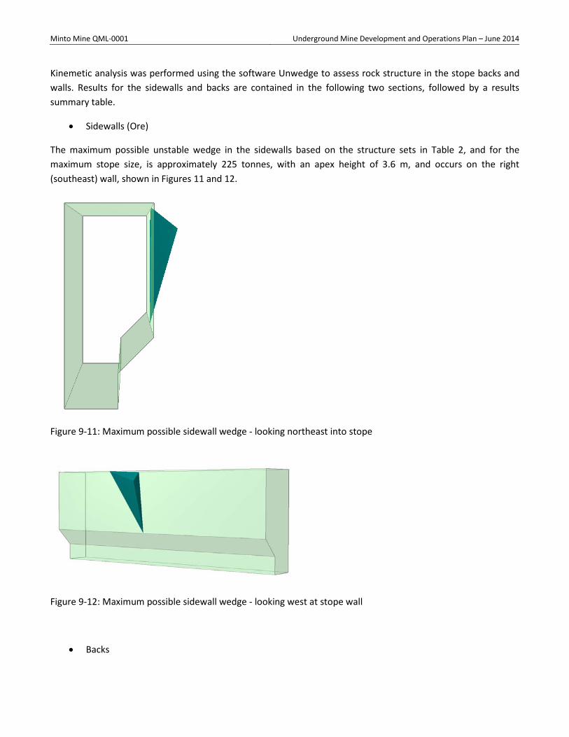
Minto Mine QML-0001 Underground Mine Development and Operations Plan – June 2014
Kinemetic analysis was performed using the software Unwedge to assess rock structure in the stope backs and walls. Results for the sidewalls and backs are contained in the following two sections, followed by a results summary table.
• Sidewalls (Ore)
The maximum possible unstable wedge in the sidewalls based on the structure sets in Table 2, and for the maximum stope size, is approximately 225 tonnes, with an apex height of 3.6 m, and occurs on the right (southeast) wall, shown in Figures 11 and 12.
Figure 9-11: Maximum possible sidewall wedge - looking northeast into stope
Figure 9-12: Maximum possible sidewall wedge - looking west at stope wall
• Backs
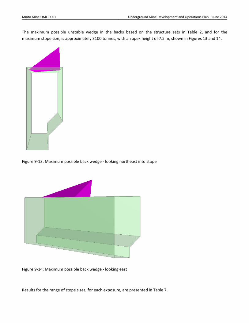
Minto Mine QML-0001 Underground Mine Development and Operations Plan – June 2014
The maximum possible unstable wedge in the backs based on the structure sets in Table 2, and for the maximum stope size, is approximately 3100 tonnes, with an apex height of 7.5 m, shown in Figures 13 and 14.
Figure 9-13: Maximum possible back wedge - looking northeast into stope
Figure 9-14: Maximum possible back wedge - looking east
Results for the range of stope sizes, for each exposure, are presented in Table 7.
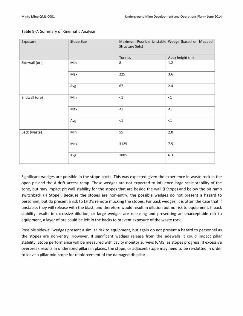
Minto Mine QML-0001 Underground Mine Development and Operations Plan – June 2014
Table 9-7: Summary of Kinematic Analysis
Exposure Stope Size Maximum Possible Unstable Wedge (based on Mapped Structure Sets)
Tonnes Apex height (m) Sidewall (ore) Min 8 1.2
Max 225 3.6
Avg 67 2.4
Endwall (ore) Min <1 <1
Max <1 <1
Avg <1 <1
Back (waste) Min 55 2.0
Max 3125 7.5
Avg 1885 6.3
Significant wedges are possible in the stope backs. This was expected given the experience in waste rock in the open pit and the A-drift access ramp. These wedges are not expected to influence large scale stability of the zone, but may impact pit wall stability for the stopes that are beside the wall (I Stope) and below the pit ramp switchback (H Stope). Because the stopes are non-entry, the possible wedges do not present a hazard to personnel, but do present a risk to LHD’s remote mucking the stopes. For back wedges, it is often the case that if unstable, they will release with the blast, and therefore would result in dilution but no risk to equipment. If back stability results in excessive dilution, or large wedges are releasing and presenting an unacceptable risk to equipment, a layer of ore could be left in the backs to prevent exposure of the waste rock.
Possible sidewall wedges present a similar risk to equipment, but again do not present a hazard to personnel as the stopes are non-entry. However, If significant wedges release from the sidewalls it could impact pillar stability. Stope performance will be measured with cavity monitor surveys (CMS) as stopes progress. If excessive overbreak results in undersized pillars in places, the stope, or adjacent stope may need to be re-slotted in order to leave a pillar mid-stope for reinforcement of the damaged rib pillar.
Minto Mine QML-0001 Underground Mine Development and Operations Plan – June 2014
7.0 Conclusion and Path Forward
The mapping completed to date indicates the properties used in numerical stress analyses completed by Itasca are reasonable and revisions to the models are not required. No major structures (faults, shear zones) have been intersected to date that should be modelled explicitly. Kinematic and empirical analyses indicate significant overbreak and wedges may occur in the stope backs. Because the stopes are non-entry this does not present a risk to personnel, however back performance will need to be closely monitored to ensure there is not unacceptable risk to remote equipment or excessive dilution.
The analyses completed are applicable to the initial stopes B to G, which are furthest from the pit wall and have been confirmed by numerical analyses to be stable and with minimal influence on the pit wall. Stopes H and I, which are in close proximity to the pit wall, will be reassessed separately as experience is gained with ground performance and mining practices in the initial stopes. Analyses for stopes H and I will be presented under separate cover.
The following measures will be taken to further verify the design as development and stoping proceeds:
• Mapping will be continued throughout the remaining development to collect more information on rock quality and structure and identify any zones of variability across the ore body.
• Cavity monitor surveys will be carried out to monitor wall and back performance during stoping. This will allow areas of excessive overbreak to be identified so that modifications to the adjacent stope, or remaining stope blasts can be designed if required.
• Cavity monitor surveys will be reconciled with stope designs to develop a site specific stability graph. • Drilling accuracy and blasting practices will be critical to minimize overbreak, particularly in the pillars.
Tolerance should be included in ring designs for the expected overbreak – this can be refined as experience is gained with drilling, blasting, and pillar performance.
• A detailed monitoring/instrumentation plan will be developed for the last two stopes near the pit wall, H and I, as experience is gained with the initial stopes.
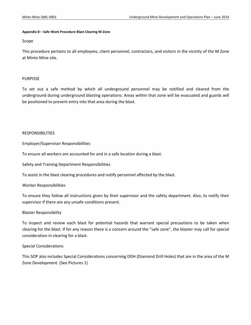
Minto Mine QML-0001 Underground Mine Development and Operations Plan – June 2014
Appendix B – Safe Work Procedure Blast Clearing M-Zone
Scope
This procedure pertains to all employees, client personnel, contractors, and visitors in the vicinity of the M Zone at Minto Mine site.
PURPOSE
To set out a safe method by which all underground personnel may be notified and cleared from the underground during underground blasting operations. Areas within that zone will be evacuated and guards will be positioned to prevent entry into that area during the blast.
RESPONSIBILITIES
Employer/Supervisor Responsibilities
To ensure all workers are accounted for and in a safe location during a blast.
Safety and Training Department Responsibilities
To assist in the blast clearing procedures and notify personnel affected by the blast.
Worker Responsibilities
To ensure they follow all instructions given by their supervisor and the safety department. Also, to notify their supervisor if there are any unsafe conditions present.
Blaster Responsibility
To inspect and review each blast for potential hazards that warrant special precautions to be taken when clearing for the blast. If for any reason there is a concern around the “safe zone”, the blaster may call for special consideration in clearing for a blast.
Special Considerations
This SOP also includes Special Considerations concerning DDH (Diamond Drill Holes) that are in the area of the M Zone Development. (See Pictures 1)
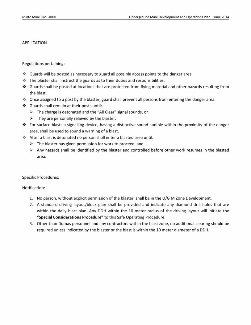
Minto Mine QML-0001 Underground Mine Development and Operations Plan – June 2014
APPLICATION
Regulations pertaining:
Guards will be posted as necessary to guard all possible access points to the danger area. The blaster shall instruct the guards as to their duties and responsibilities. Guards shall be posted at locations that are protected from flying material and other hazards resulting from
the blast. Once assigned to a post by the blaster, guard shall prevent all persons from entering the danger area. Guards shall remain at their posts until: The charge is detonated and the “All Clear” signal sounds, or They are personally relieved by the blaster.
For surface blasts a signalling device, having a distinctive sound audible within the proximity of the danger area, shall be used to sound a warning of a blast.
After a blast is detonated no person shall enter a blasted area until: The blaster has given permission for work to proceed, and Any hazards shall be identified by the blaster and controlled before other work resumes in the blasted
area.
Specific Procedures:
Notification:
1. No person, without explicit permission of the blaster, shall be in the U/G M Zone Development. 2. A standard driving layout/block plan shall be provided and indicate any diamond drill holes that are
within the daily blast plan. Any DDH within the 10 meter radius of the driving layout will initiate the “Special Considerations Procedure” to this Safe Operating Procedure.
3. Other than Dumas personnel and any contractors within the blast zone, no additional clearing should be required unless indicated by the blaster or the blast is within the 10 meter diameter of a DDH.
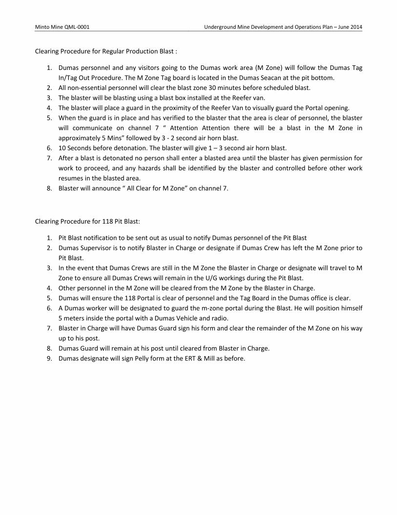
Minto Mine QML-0001 Underground Mine Development and Operations Plan – June 2014
Clearing Procedure for Regular Production Blast :
1. Dumas personnel and any visitors going to the Dumas work area (M Zone) will follow the Dumas Tag In/Tag Out Procedure. The M Zone Tag board is located in the Dumas Seacan at the pit bottom.
2. All non-essential personnel will clear the blast zone 30 minutes before scheduled blast. 3. The blaster will be blasting using a blast box installed at the Reefer van. 4. The blaster will place a guard in the proximity of the Reefer Van to visually guard the Portal opening. 5. When the guard is in place and has verified to the blaster that the area is clear of personnel, the blaster
will communicate on channel 7 “ Attention Attention there will be a blast in the M Zone in approximately 5 Mins” followed by 3 - 2 second air horn blast.
6. 10 Seconds before detonation. The blaster will give 1 – 3 second air horn blast. 7. After a blast is detonated no person shall enter a blasted area until the blaster has given permission for
work to proceed, and any hazards shall be identified by the blaster and controlled before other work resumes in the blasted area.
8. Blaster will announce “ All Clear for M Zone” on channel 7.
Clearing Procedure for 118 Pit Blast:
1. Pit Blast notification to be sent out as usual to notify Dumas personnel of the Pit Blast 2. Dumas Supervisor is to notify Blaster in Charge or designate if Dumas Crew has left the M Zone prior to
Pit Blast. 3. In the event that Dumas Crews are still in the M Zone the Blaster in Charge or designate will travel to M
Zone to ensure all Dumas Crews will remain in the U/G workings during the Pit Blast. 4. Other personnel in the M Zone will be cleared from the M Zone by the Blaster in Charge. 5. Dumas will ensure the 118 Portal is clear of personnel and the Tag Board in the Dumas office is clear. 6. A Dumas worker will be designated to guard the m-zone portal during the Blast. He will position himself
5 meters inside the portal with a Dumas Vehicle and radio. 7. Blaster in Charge will have Dumas Guard sign his form and clear the remainder of the M Zone on his way
up to his post. 8. Dumas Guard will remain at his post until cleared from Blaster in Charge. 9. Dumas designate will sign Pelly form at the ERT & Mill as before.
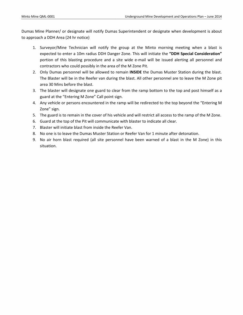
Minto Mine QML-0001 Underground Mine Development and Operations Plan – June 2014
Dumas Mine Planner/ or designate will notify Dumas Superintendent or designate when development is about to approach a DDH Area (24 hr notice)
1. Surveyor/Mine Technician will notify the group at the Minto morning meeting when a blast is expected to enter a 10m radius DDH Danger Zone. This will initiate the “DDH Special Consideration” portion of this blasting procedure and a site wide e-mail will be issued alerting all personnel and contractors who could possibly in the area of the M Zone Pit.
2. Only Dumas personnel will be allowed to remain INSIDE the Dumas Muster Station during the blast. The Blaster will be in the Reefer van during the blast. All other personnel are to leave the M Zone pit area 30 Mins before the blast.
3. The blaster will designate one guard to clear from the ramp bottom to the top and post himself as a guard at the “Entering M Zone” Call point sign.
4. Any vehicle or persons encountered in the ramp will be redirected to the top beyond the “Entering M Zone” sign.
5. The guard is to remain in the cover of his vehicle and will restrict all access to the ramp of the M Zone. 6. Guard at the top of the Pit will communicate with blaster to indicate all clear. 7. Blaster will initiate blast from inside the Reefer Van. 8. No one is to leave the Dumas Muster Station or Reefer Van for 1 minute after detonation. 9. No air horn blast required (all site personnel have been warned of a blast in the M Zone) in this
situation.
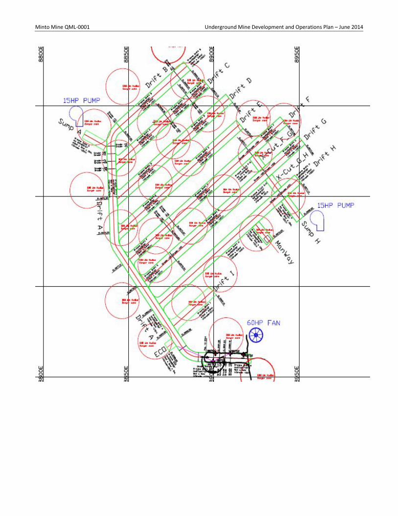
Minto Mine QML-0001 Underground Mine Development and Operations Plan – June 2014
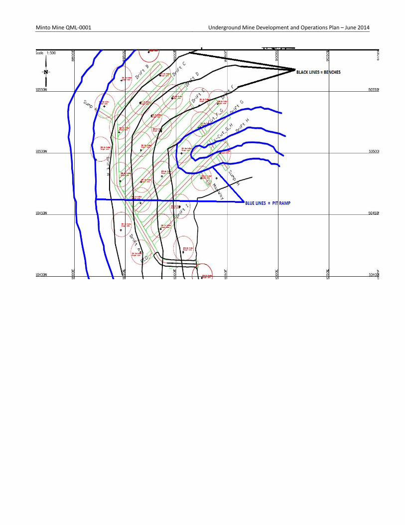
Minto Mine QML-0001 Underground Mine Development and Operations Plan – June 2014
Minto Mine QML-0001 Underground Mine Development and Operations Plan – June 2014
Reviewed by:
Project Manager: _________________________Date: _________________________
U/G Superintendent: _________________________Date: _________________________
U/G Shifter: _________________________Date: _________________________
Safety Department: _________________________Date: _________________________
Worker Rep. _________________________Date: _________________________
Minto Representatives:
_________________________Date__________________________
_________________________Date__________________________
_________________________Date__________________________
_________________________Date__________________________
Name Date Name Date

Minto Mine QML-0001 Underground Mine Development and Operations Plan – June 2014
Appendix C – Minto Mine Emergency Response Plan – March 2014
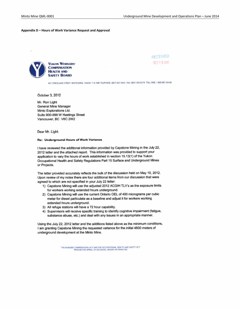
Minto Mine QML-0001 Underground Mine Development and Operations Plan – June 2014
Appendix D – Hours of Work Variance Request and Approval
Minto Mine QML-0001 Underground Mine Development and Operations Plan – June 2014
Minto Mine QML-0001 Underground Mine Development and Operations Plan – June 2014
Appendix E – Fatigue Management Plan
Minto Mine
Capstone Mining Corporation's
Fatigue Risk Management Plan (FRMP) - DRAFT Copy
Capstone's FRMP EHS Partnerships P a g e | 1
Table of Contents
Introduction ................................................................................................................................................ 3
Scope of FRMP ............................................................................................................................................ 3
Objectives ................................................................................................................................................... 3
Communication Strategies ............................................................................................................................ 3
Minto Explorations Fatigue Management Policy Statement ........................................................................ 4
Definitions ................................................................................................................................................... 5
Standards and Legislation ............................................................................................................................. 6
Emergency Response .................................................................................................................................. 6
Training ....................................................................................................................................................... 6
Roles and Responsibilities ............................................................................................................................. 7
Understanding Fatigue ................................................................................................................................ 8
Fatigue Risk Assessments Completed at Minto Mine ................................................................................... 9
Fatigue Management Plans ........................................................................................................................ 11
A Brief Overview of the 5 Level Fatigue Risk Management Plan ................................................................ 12
Level 1 - 5 Supporting Processes and Procedures ...................................................................................... 16
Level 1 - Understanding Management Influences on Sleep Opportunities ............................................ 16
Level 2 Controls - Worker Self-Reporting of Sleep Obtained ................................................................. 18
Level 3 Controls - Workers and Supervisors Work Together to Ensure Fatigue Risks are Controlled. ... 20
Minto Mine QML-0001 Underground Mine Development and Operations Plan – June 2014
Level 4 - Fatigue Related Errors - Assessing the System ......................................................................... 22
Level 5 - Fatigue Related Incidents - Fatigue Incident Investigation Information Required .................. 22
Capstone Fatigue Incident Investigation Information .............................................................. 23
Implementation Strategies ......................................................................................................................... 25
Implementation Role Clarification .......................................................................................................... 25
Suggested Time Frames .......................................................................................................................... 26
Communication Strategies ...................................................................................................................... 27
Planned Audit and Review ...................................................................................................................... 28
Appendices ................................................................................................................................................ 29
Appendix A: References ......................................................................................................................... 30
Appendix B: Terms and Definitions ........................................................................................................ 31
Appendix C: Fatigue Hazard Assessment at Minto Mine ....................................................................... 35
Appendix D: Fatigue Factors Minto Mine Checklist ............................................................................... 38
Appendix E: Fatigue Management Plan Self-Assessment Worksheet ................................................... 39
Capstone's FRMP EHS Partnerships P a g e | 2
Introduction
This policy was developed in consultation with Minto Mine management, supervisors, workers and contractors. It is reflective of current research and knowledge of fatigue and safety management systems, with a focus on fatigue risk management. It is designed to align closely with the existing Safety Management Systems at Minto Mine. It is based upon a five level fatigue risk management strategy that is designed to provide multiple layers of controls to assist in mitigating fatigue risk factors.
Scope of FRMP
This policy and supporting procedures apply to all supervisors and workers in the underground mine operations at Minto including direct Capstone employees, contractors or employees of contractors. Any worker who will, at any time, be spending more than 8 hours underground in the mine, shall comply with this Fatigue Risk Management Plan to ensure they maintain the capacity to safely perform work.
Objectives
Minto Mine QML-0001 Underground Mine Development and Operations Plan – June 2014
This Fatigue Risk Management Plan seeks to mitigate risk factors associated with fatigue in Minto Mine's underground mining operations.
The key objectives of this Fatigue Risk Management Plan are to ensure a safe and healthy working environment free of fatigue related injury or illness by:
• controlling work related fatigue risk factors to minimize the likelihood of a worker being fatigued;
• minimising the risks of persons presenting for work or conducting work while impaired by fatigue;
• establishing appropriate steps to manage persons who are effected by fatigue; and
• reducing the likelihood of a fatigue related error or incident.
Communication Strategies
To ensure a common understanding of Capstone's Fatigue Risk Management Plan, a copy of the plan will be made available to all supervisors and workers involved in underground mining operations. The Minto Explorations Fatigue Management Policy Statement will be displayed in a visually accessible place to demonstrate commitment to properly mitigating fatigue factors.
Capstone's FRMP EHS Partnerships P a g e | 3
Minto Explorations Fatigue Management Policy Statement
Minto Explorations Ltd. believes that the health and safety of its employees is fundamental to its business operations. Work related injury or illness is unacceptable and the company is committed to the identification, elimination, or control of workplace hazards for the protection of all employees. The goal is to have zero lost time accidents. The company is committed to implementing operational improvements that offer superior safety and occupational health management.
The management of fatigue in the underground mines is an integral part of Capstone's “Fit for Duty” Policy and as such, is a shared responsibility between Capstone, its contractors and its employees. All employees in the underground mining operations must undertake their work in accordance with this policy to the best of their ability and to take all reasonable care for their own safety and health, as well as the health and safety of their work colleagues.
Minto Explorations Ltd. understands fatigue is a risk factor and as such is committed to the following:
1. Zero harm to personnel due to fatigue related error.
2. Operating in accordance with industry standards, while meeting or exceeding compliance with all relevant legislative requirements.
Minto Mine QML-0001 Underground Mine Development and Operations Plan – June 2014
3. Providing the expertise and resources needed to maintain a fatigue risk management system designed to recognize and manage fatigue risks to create safe systems of work and safe and healthy work environments.
4. Promoting fatigue awareness through appropriate training and education to ensure workers and supervisors are able to effectively manage fatigue and are able to communicate openly about fatigue related issues.
5. Ensuring employees understand their right and obligation to protect themselves from workplace hazards and alter or stop work if they believe fatigue is compromising the safety of themselves or others.
6. Ensuring all underground mine employees, sub-contractors and visitors are informed of, understand their obligations, and comply with this policy.
7. Measuring health and safety performance with regards to fatigue, the effectiveness of this policy in managing fatigue, and making improvements as warranted.
8. Investigating the causes of accidents and incidents including reviewing fatigue factors, and developing effective and immediate preventative and remedial actions as needed.
______________________________
Sebastian Tolgyesi
Minto Mine Manger
Capstone's FRMP EHS Partnerships P a g e | 4
Definitions
For the purpose of this document, the following definitions apply:
Fatigue: A physiological state of reduced mental or physical performance capability resulting from sleep loss or extended wakefulness, circadian phase, or workload (mental and/or physical activity) that can impair a worker's alertness and ability to safely perform their duties. (This definition is modified from Aviation IFALPA IATA FRMS for Operators, 2011).
A Fatigue Risk Management Plan (FRMP) is an integrated set of management practices, beliefs and procedures for monitoring and managing the risks posed to health and safety by fatigue. It is based
on safety management system theory with an emphasis on risk management.
Capstone's FRMP incorporates:
The FRMP Document: The FRMP document defines and details the way that fatigue-related risk is dealt with in the underground mine at Minto, and is the written version of the FRMP.
Minto Mine QML-0001 Underground Mine Development and Operations Plan – June 2014
Risk Mitigation Strategies: Contained within the FRMP are five levels of defenses designed to reduce the likelihood of a fatigue related error occurring. The FRMP includes tools, strategies and control measures for monitoring and managing fatigue-related risk.
Education and Training: All underground mine employees need to be aware of the risks posed by fatigue, understand the importance of controlling fatigue risk factors and understand the individual and organisational strategies that are employed in managing that risk. This is facilitated through both supervisor and worker education and training programs.
Revision and Review Functions: The system must be monitored for continuous improvement and to ensure it is flexible to changing work practices. The review function is essential and is therefore built into the Capstone FRMP framework.
Employee/Worker: Any person who works on the site, regardless of their employer. This includes direct Capstone employees, contractors and their employees.
Manager/Supervisor: Any person who is directly responsible for the supervision and well-being of other employees.
Company/Employer: Capstone Mining Corporation or Minto Explorations Ltd.
Contractor: A company hired by Capstone Mining Corp. to complete work on site. Employees of the contractor are referred to as employees/workers or managers/supervisors.
FRMP: Fatigue Risk Management Plan.
Shift: The hours between the start and finish of established daily work schedules.
Work Rotations/Cycles: The working period scheduled between any significant break away from work.
Work Schedules/Rosters: The hours to be worked for each day, shift, week, month or year, as
scheduled by the employer.
A complete list of definitions and terms related to this document can be found in Appendix B.
Capstone's FRMP EHS Partnerships P a g e | 5
Standards and Legislation
The following standards and legislation were consulted in the preparation of this FRMP.
O.I.C. 2006/178
YUKON OCCUPATIONAL HEALTH AND SAFETY ACT
Minto Mine QML-0001 Underground Mine Development and Operations Plan – June 2014
REGULATIONS: PART 15 – SURFACE and UNDERGROUND MINES or PROJECTS
Hours underground 15.13
(1) A worker shall only remain underground in an underground mine or project for more than eight hours in any consecutive 24 hours, measured from the time the worker enters to the time the worker leaves the underground workings:
(a) when an emergency causes an extension of the time,
(b) on one day of a week but only for the purpose of changing shift, or
(c) if the worker is a supervisor, pump worker, cage tender, or a person engaged
solely in surveying or measuring or in emergency repair work.
(2) The director may consider and approve an application for a modified hours of work schedule in an underground mine if the director is satisfied that the risk to the health or safety of the workers is not increased.
“Underground mine or underground project” means a mine or project that is not a surface mine and includes any work, undertaking or facility used in connection therewith.
Emergency Response
An emergency is defined in Capstone's Safety Management System. In the event of an emergency, workers and supervisors may be required to work outside of normal shift hours and fatigue may become a key safety issue. In the case of an emergency, all efforts should be made to properly mitigate fatigue risk factors through risk management strategies contained within this FRMP. Supervisors should be extra diligent in monitoring fatigue and in assisting workers in being aware of and managing fatigue to the best of their abilities. If possible, the emergency response manager should conduct regular fatigue assessments to determine if fatigue will become a safety hazard. When the emergency situation has finalized, all workers should be allowed a sufficient period to rest prior to recommencing work duties.
Training
Improving supervisor and worker competency in understanding, assessing and controlling fatigue risk factors, is an integral component of Capstone's FRMP. Specific training programs have been designed and delivered to key Minto employees involved in the underground mining operations. All new workers who will be involved in the underground mining operations will be trained in fatigue competency as part of their on-boarding process. Training records will be kept up-to-date to ensure fatigue competency.
Capstone's FRMP EHS Partnerships P a g e | 6
Roles and Responsibilities
Minto Mine QML-0001 Underground Mine Development and Operations Plan – June 2014
Capstone and all of its underground mining personnel share in the responsibility to minimize and manage the adverse effects of work related fatigue. As with all Safety Management Systems, the FRMP recognizes an integral role played by management, contractors and workers. Broadly, roles and responsibilities are outlined below.
Workers are responsible for:
• Obtaining sufficient sleep to be fit for work.
• Reporting when they have been unable to obtain sufficient sleep or when they feel at risk of making a fatigue related error.
• Complying with implemented Fatigue Risk Management Plans and policies including following all processes and completing all required documentation related to Capstone's FRMP.
• Participating in fatigue related education and training provided by Capstone.
• Participating in fatigue investigations as required.
• Seeking medical or other assistance with fatigue related health issues (such as illness or sleep disorders).
• Addressing any concerns regarding fatigue with a supervisor as required.
Supervisors are responsible for:
• Ensuring new workers are oriented and informed about issues relating to fatigue and the Capstone FRMP.
• Providing ongoing information and awareness to all underground mining workers regarding fatigue risk factors.
• Ensuring workers are following procedures and processes outlined in Capstone's FRMP.
• Conducting regular health and safety meetings that periodically discuss Fatigue Risk Management.
• Ensuring all observed and reported fatigue symptoms are properly addressed through consultation with workers and through agreed actions within the Capstone FRMP.
• Taking action if an employee is not fit for work due to fatigue.
• Reviewing and investigating all reports of fatigue related errors and incidents.
• Ensuring Capstone Fatigue Incident Investigation Information is gathered as part of any underground mine incident investigation.
• Setting a good example for workers by properly managing fatigue factors.
• Addressing any concerns regarding fatigue with workers and management as required.
Minto Mine QML-0001 Underground Mine Development and Operations Plan – June 2014
Employer is responsible for:
• Creating and implementing a Fatigue Risk Management Plan and control strategies to mitigate fatigue related risk.
• Providing resources necessary for education and training to assist workers in building competency in identifying, assessing and controlling fatigue.
• Scheduling work to ensure adequate sleep opportunities for workers.
• Providing conditions that are conducive to managing fatigue, specifically providing adequately for nutritional, hydration and fitness needs of workers while at Minto Camp.
• Providing a proper sleep environment for workers when on duty at Minto Camp.
• Ensuring resources are available to maintain and regularly review and revise the FRMP.
• Supporting employees with non-work fatigue related issues through existing health and safety programs.
Capstone's FRMP EHS Partnerships P a g e | 7 Fatigue Causes9FatigueWorker –Individual FactorsWork EnvironmentWork SchedulingWork TasksOther Factors
Understanding Fatigue
Understanding fatigue is a key component of any fatigue risk management plan. It is essential for supervisors and workers to understand fatigue factors to be able to properly identify assess and mitigate fatigue risks.
Information required for understanding fatigue includes: circadian rhythms, sleep cycles, causes of fatigue, effects of fatigue, identifying signs of fatigue, and methods of controlling and managing fatigue. These key understandings are an integral part of the supervisor and worker training programs that are provided to all personnel involved in the underground mining operations. These training programs ensure all personnel involved have the understanding and competencies required to properly manage fatigue risk factors. A very brief summary of fatigue understandings is provided below.
Fatigue is an issue because it can impair a workers abilities and can significantly increase the risk of a safety incident occurring. Fatigue causes an increased risk of incidents because of reduced physical and mental abilities and an overall lack of worker alertness. When workers are fatigued they are more likely to have reduced awareness and reduced abilities to respond to changes in their working environment, to react emotionally and/or to exercise poor judgement. This leads to an increased likelihood of incidents occurring due to human error. Fatigue has also been positively linked to multiple long term health concerns such as: digestive issues, ulcers, obesity, diabetes, heart disease, stroke, and immune system deficiencies.
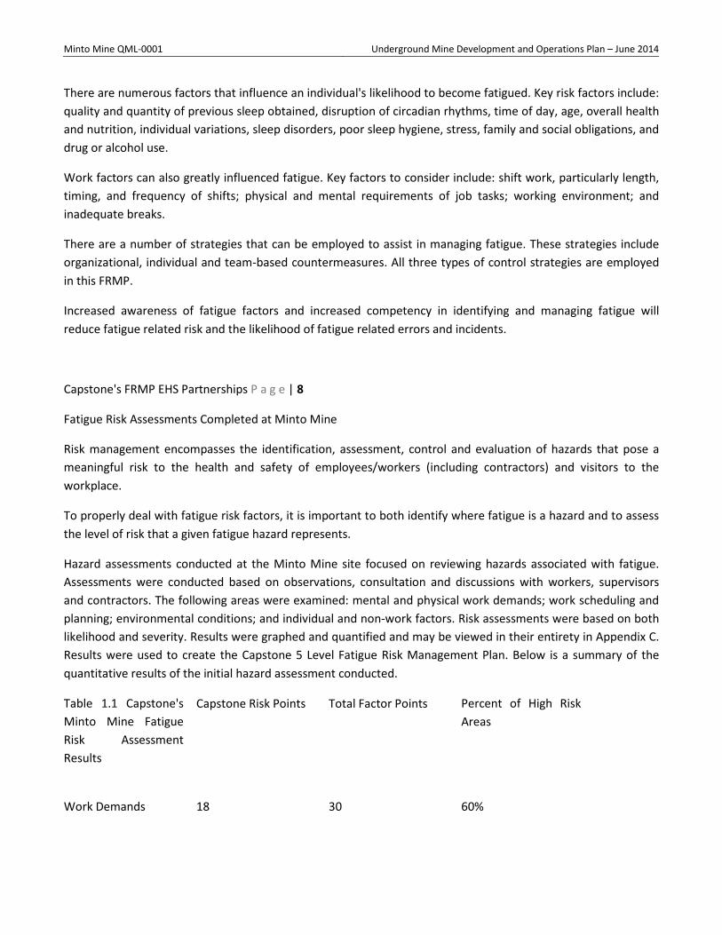
Minto Mine QML-0001 Underground Mine Development and Operations Plan – June 2014
There are numerous factors that influence an individual's likelihood to become fatigued. Key risk factors include: quality and quantity of previous sleep obtained, disruption of circadian rhythms, time of day, age, overall health and nutrition, individual variations, sleep disorders, poor sleep hygiene, stress, family and social obligations, and drug or alcohol use.
Work factors can also greatly influenced fatigue. Key factors to consider include: shift work, particularly length, timing, and frequency of shifts; physical and mental requirements of job tasks; working environment; and inadequate breaks.
There are a number of strategies that can be employed to assist in managing fatigue. These strategies include organizational, individual and team-based countermeasures. All three types of control strategies are employed in this FRMP.
Increased awareness of fatigue factors and increased competency in identifying and managing fatigue will reduce fatigue related risk and the likelihood of fatigue related errors and incidents.
Capstone's FRMP EHS Partnerships P a g e | 8
Fatigue Risk Assessments Completed at Minto Mine
Risk management encompasses the identification, assessment, control and evaluation of hazards that pose a meaningful risk to the health and safety of employees/workers (including contractors) and visitors to the workplace.
To properly deal with fatigue risk factors, it is important to both identify where fatigue is a hazard and to assess the level of risk that a given fatigue hazard represents.
Hazard assessments conducted at the Minto Mine site focused on reviewing hazards associated with fatigue. Assessments were conducted based on observations, consultation and discussions with workers, supervisors and contractors. The following areas were examined: mental and physical work demands; work scheduling and planning; environmental conditions; and individual and non-work factors. Risk assessments were based on both likelihood and severity. Results were graphed and quantified and may be viewed in their entirety in Appendix C. Results were used to create the Capstone 5 Level Fatigue Risk Management Plan. Below is a summary of the quantitative results of the initial hazard assessment conducted.
Table 1.1 Capstone's Minto Mine Fatigue Risk Assessment Results Factor Grouping
Capstone Risk Points Total Factor Points Percent of High Risk Areas
Work Demands 18 30 60%
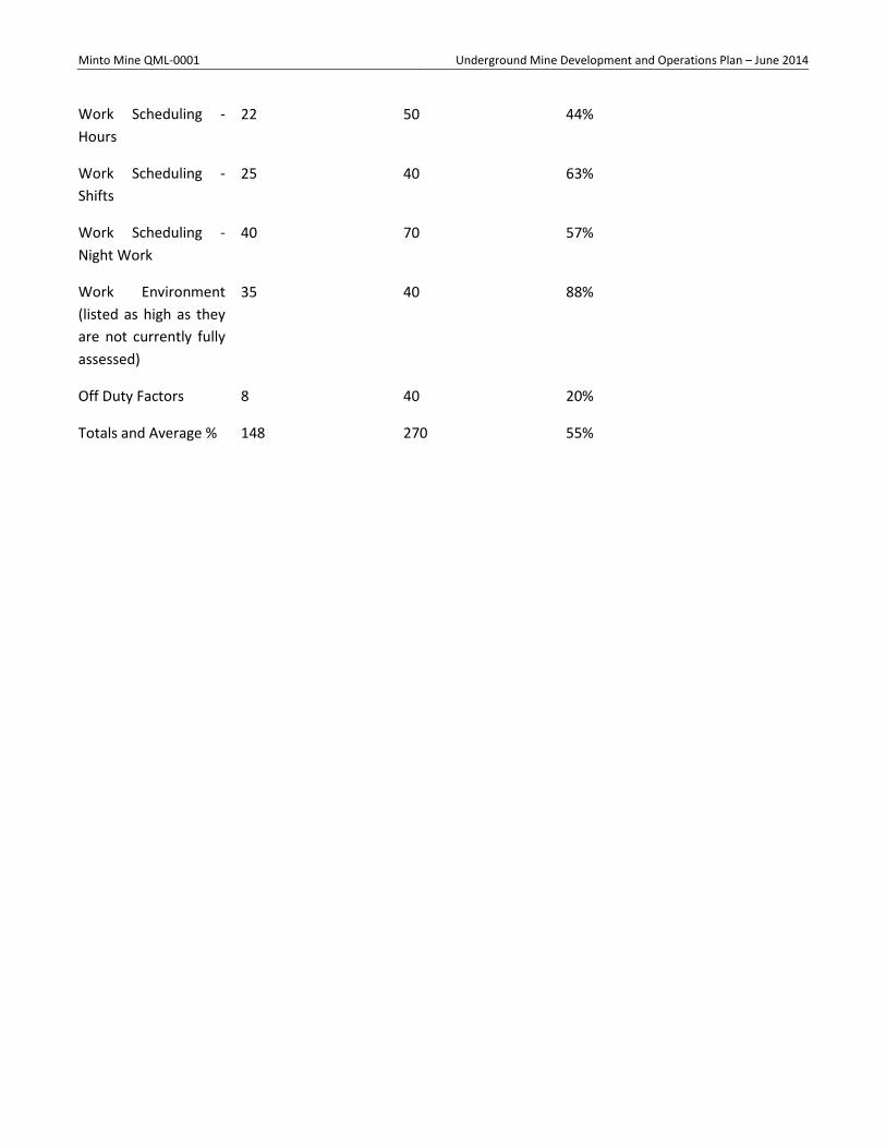
Minto Mine QML-0001 Underground Mine Development and Operations Plan – June 2014
Work Scheduling - Hours
22 50 44%
Work Scheduling - Shifts
25 40 63%
Work Scheduling - Night Work
40 70 57%
Work Environment (listed as high as they are not currently fully assessed)
35 40 88%
Off Duty Factors 8 40 20%
Totals and Average % 148 270 55%

END PAGE