minimum requirements for receivers of free to … · free to air digital terrestrial television...
TRANSCRIPT

MINIMUM REQUIREMENTS FOR RECEIVERS OF FREE TO AIR DIGITAL TERRESTRIAL TELEVISION
(DTT) IN GHANA v1.1a
June 2016
NATIONAL COMMUNICATIONS AUTHORITY
ii
VERSION OF THE DOCUMENT
Date Version Comments January, 2013 1.0 First official publication
December, 2013 1.1 First Revision to establish conformance with ECOWAS Minimum Specification
June, 2016 1.1a Table 5 under Section 4.2.1 updated with “Note 4”
iii
Table of Contents VERSION OF THE DOCUMENT ................................................................................................................................ II
REFERENCES .......................................................................................................................................................... V
LIST OF ABBREVIATIONS AND SYMBOLS............................................................................................................... VI
LIST OF TABLES ...................................................................................................................................................... X
LIST OF FIGURES .................................................................................................................................................... X
1 INTRODUCTION ...........................................................................................................................................11
2 SCOPE .........................................................................................................................................................17
3 DEFINITIONS ...............................................................................................................................................18
4 PERFORMANCE REQUIREMENTS .................................................................................................................20
4.1 SPECTRUM AND DTT MODULATION AND CODING ..................................................................................................... 21 4.2 RADIO FREQUENCY ............................................................................................................................................. 21 4.3 DEMULTIPLEXING AND DECODING ......................................................................................................................... 32 4.4 SUBTITLING ...................................................................................................................................................... 38 4.5 TELETEXT ......................................................................................................................................................... 39 4.6 SERVICE INFORMATION (SI) AND PROGRAM-SPECIFIC INFORMATION (PSI) .................................................................... 39 4.7 MEMORY ......................................................................................................................................................... 44 4.8 GRAPHICS CAPABILITIES ....................................................................................................................................... 44 4.9 STANDBY OPERATION.......................................................................................................................................... 45 4.10 POWER SUPPLY ............................................................................................................................................. 46 4.11 INTERFACES ................................................................................................................................................. 46
5 APPLICATIONS .............................................................................................................................................48
5.1 HBBTV INTERACTIVE APPLICATION ENVIRONMENT .................................................................................................... 48 5.2 ELECTRONIC PROGRAM GUIDE (EPG) .................................................................................................................... 48 5.3 LANGUAGES AND FONTS ..................................................................................................................................... 49 5.4 SECURE DOWNLOADS AND UPDATES ...................................................................................................................... 49
6 USER INTERFACE .........................................................................................................................................49
6.1 NOW AND NEXT BANNER .................................................................................................................................... 49 6.2 ON-SCREEN MENU ............................................................................................................................................ 50 6.3 OPERATION AT FIRST-TIME SWITCH-ON .................................................................................................................. 55 6.4 TIME AND DATE INFORMATION ............................................................................................................................. 55 6.5 PARENTAL CONTROL ........................................................................................................................................... 56
7 REMOTE CONTROL UNIT (RCU) ...................................................................................................................57
7.1 MINIMUM FUNCTIONALITY .................................................................................................................................. 57 7.2 ALTERNATIVE RCU DESIGN .................................................................................................................................. 58 7.3 RELIABILITY ....................................................................................................................................................... 58 7.4 PACKAGING ...................................................................................................................................................... 59
8 COMPLIANCE ..............................................................................................................................................59
8.1 HEALTH AND SAFETY ........................................................................................................................................... 59

iv
8.2 ELECTROMAGNETIC COMPATIBILITY (EMC) ............................................................................................................. 59 8.3 PERFORMANCE .................................................................................................................................................. 59
9 ACCESSORIES ..............................................................................................................................................59
10 PACKAGING .................................................................................................................................................60
11 E-WASTE DISPOSAL .....................................................................................................................................60
ANNEX A: COUNTRY SPECIFIC INFORMATION ......................................................................................................61
1. DVB IDENTIFIERS ............................................................................................................................................... 61 2. LANGUAGES AND FONTS ..................................................................................................................................... 62 3. PLUGS & APPLIANCE CONNECTORS ....................................................................................................................... 63
v
REFERENCES
The following referenced documents are indispensable for the application of this document. Information on currently valid national and international standards can be obtained from the Ghana Standards Authority.
[1] ETSI EN 302 755 V.1.3.1, Frame structure channel coding and modulation for a second generation digital terrestrial television broadcasting system (DVB-T2);
[2] ETSI TS 101 162 V1.5.1, Digital Video Broadcasting (DVB); Allocation of identifiers and codes for Digital Video Broadcasting (DVB) systems;
[3] ETSI TS 102 773 1.3.1, Digital Video Broadcasting (DVB); Modulator Interface (T2-MI) for a second generation digital terrestrial television broadcasting system (DVB-T2);
[4] ETSI TS 102 831 V1.2.1, Digital Video Broadcasting (DVB); Implementation guidelines for a second generation digital terrestrial television broadcasting system (DVB-T2);
[5] ETSI TS 102 992 V1.1.1, Digital Video Broadcasting (DVB); Structure and modulation of optional transmitter signatures (T2-TX-SIG) for use with the DVB-T2 second generation digital terrestrial television broadcasting system;
[6] ETSI EN 300 468 V1.13.1, Specification for Service Information (SI) in DVB systems;
[7] ETSI TS 101 211 V1.11.1, Digital Video Broadcasting (DVB); Guidelines on implementation and usage of Service Information (SI);
[8] ETSI EN 300 472 V1.3.1, Digital Video Broadcasting (DVB); Specification for conveying ITU-R System B Teletext in DVB bitstreams;
[9] ETSI EN 300 743 V1.4.1, Digital Video Broadcasting (DVB); Subtitling systems;
[10] ETSI TS 102 006 V1.3.2, Digital Video Broadcasting (DVB); Specification for System Software Update in DVB Systems;
[11] ETSI TS 101 154 V1.11.1, Digital Video Broadcasting (DVB); Specification for the use of Video and Audio Coding in Broadcasting Applications based on the MPEG-2 Transport Stream;
[12] ISO/IEC 14496-1:2010/Amd 1:2010, Synchronization and multiplexing of video and audio;
[13] ISO/IEC 14496-3:2009/Amd 1:2009, Coding of audio-visual objects;
[14] ISO/IEC 14496-10:2012 Advanced video coding (AVC);
[15] ETSI TS 102 366 V1.2.1, Digital Audio Compression (AC-3, E-AC-3) Standard
[16] ITU-R BT.624-4 (1990), Characteristics of television systems.
[17] ETSI TS 102 796 V.1.1.1, Hybrid Broadcast Broadband TV (HbbTV)
[18] CI Plus Specification V.1.3(2011), Content Security Extensions to the Common Interface
[19] Nordig Unified V2.4 NorDig Unified Requirements for Integrated Receiver Decoders for use in cable, satellite, terrestrial and IP-based networks

vi
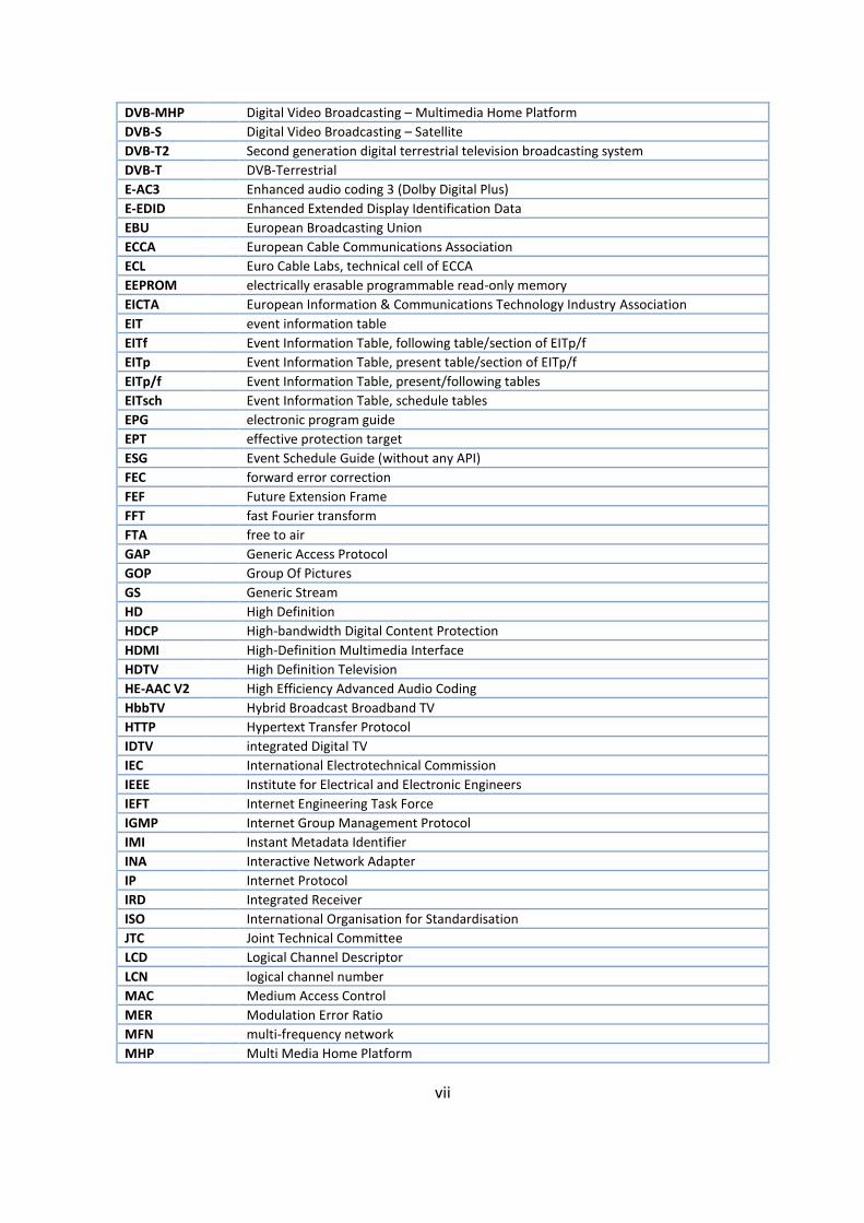
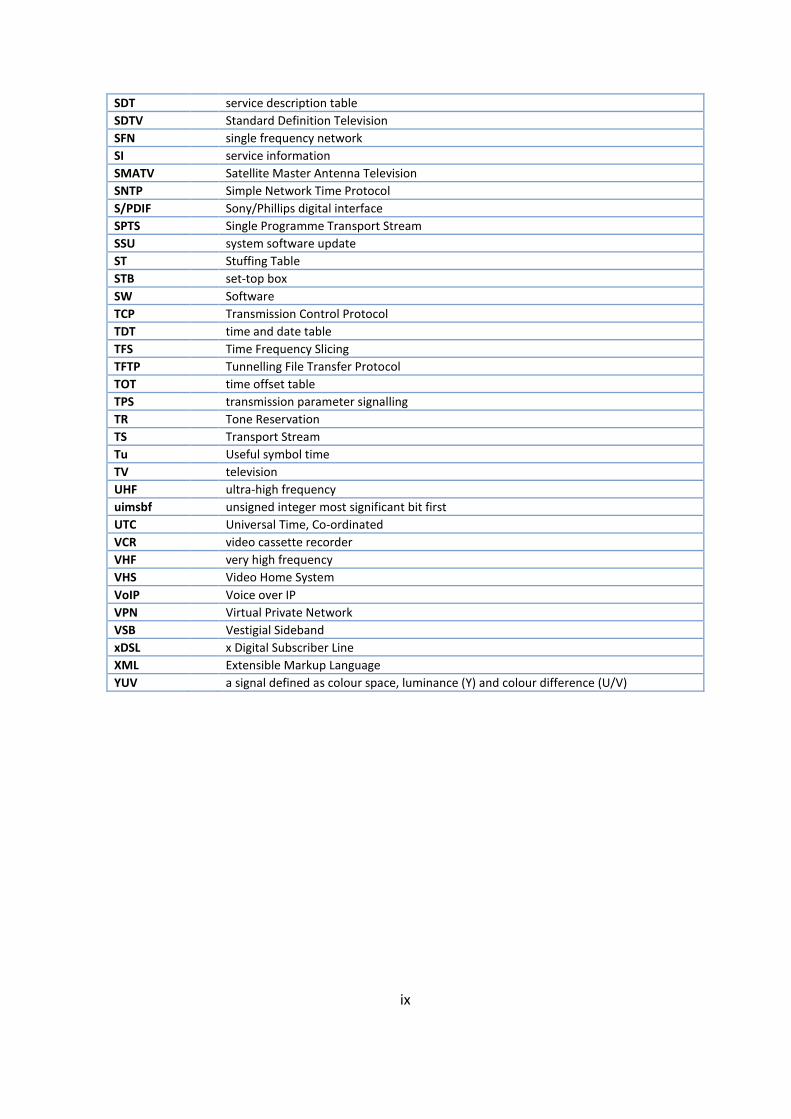
LIST OF ABBREVIATIONS AND SYMBOLS
AC-3 Audio coding 3 (Dolby Digital) AD audio description AFC automatic frequency control AFD active format descriptor AFNOR Association Francaise de Normalisation API Application Programming Interface ARC Audio Return Channel of an HDMI input BAT bouquet association table BCD Binary Coded Decimal BDR Broadcast Discovery Record (part of SD&S) BER bit error rate BOOTP Bootstrap Protocol bslbf bit string, left bit first bw bandwidth C/(N+I) ratio of carrier to noise plus interference C/N carrier to noise ratio CATV Community Antenna Television CEA Consumer Electronics Association (North American Association) CENELEC Comité Européen de Normalisation Electrotechnique CI Common Interface CID Content Identifier descriptor CIF Common Intermediate Format COFDM coded orthogonal frequency division multiplexing CPU central processing unit CRC cyclic redundancy check CRID Content Reference Identifier CSO Composite Second Order CTB Composite Triple Beat CVBS composite video baseband signal D/A Digital-to-Analogue converter DAD Default Authority Descriptor DAVIC Digital Audio-Visual Council dBFS dB Full Scale DBMC Digital Broadcasting Migration Committee DDS Display definition segment DDWG Digital Display Working Group DECT Digital Enhanced Cordless Telecommunications DHCP Dynamic Host Configuration Protocol DSB Double Side Band DSM-CC Digital Storage Media Command and Control DTT digital terrestrial television DVB Digital Video Broadcasting DVB-C Digital Video Broadcasting – Cable DVB-CAM CA-module that complies with the DVB Common Interface specification DVB-data Digital Video Broadcasting – Data Broadcasting
vii
DVB-MHP Digital Video Broadcasting – Multimedia Home Platform DVB-S Digital Video Broadcasting – Satellite DVB-T2 Second generation digital terrestrial television broadcasting system DVB-T DVB-Terrestrial E-AC3 Enhanced audio coding 3 (Dolby Digital Plus) E-EDID Enhanced Extended Display Identification Data EBU European Broadcasting Union ECCA European Cable Communications Association ECL Euro Cable Labs, technical cell of ECCA EEPROM electrically erasable programmable read-only memory EICTA European Information & Communications Technology Industry Association EIT event information table EITf Event Information Table, following table/section of EITp/f EITp Event Information Table, present table/section of EITp/f EITp/f Event Information Table, present/following tables EITsch Event Information Table, schedule tables EPG electronic program guide EPT effective protection target ESG Event Schedule Guide (without any API) FEC forward error correction FEF Future Extension Frame FFT fast Fourier transform FTA free to air GAP Generic Access Protocol GOP Group Of Pictures GS Generic Stream HD High Definition HDCP High-bandwidth Digital Content Protection HDMI High-Definition Multimedia Interface HDTV High Definition Television HE-AAC V2 High Efficiency Advanced Audio Coding HbbTV Hybrid Broadcast Broadband TV HTTP Hypertext Transfer Protocol IDTV integrated Digital TV IEC International Electrotechnical Commission IEEE Institute for Electrical and Electronic Engineers IEFT Internet Engineering Task Force IGMP Internet Group Management Protocol IMI Instant Metadata Identifier INA Interactive Network Adapter IP Internet Protocol IRD Integrated Receiver ISO International Organisation for Standardisation JTC Joint Technical Committee LCD Logical Channel Descriptor LCN logical channel number MAC Medium Access Control MER Modulation Error Ratio MFN multi-frequency network MHP Multi Media Home Platform

viii
MPEG moving picture experts group MPTS Multi Programme Transport Stream MTU Maximum Transfer Unit NEC Nippon Electric Company NEM Network Element Management NF noise figure NIC Network Interface Card NICAM Near Instantaneous Companded Audio Multiplex NIT network information table NT Network Termination in general NVOD Near Video On Demand NVRAM non-volatile random access memory OSD On Screen Display PAL phase alternating line PAPR Peak-to-Average-Power Ratio PAT Program Association Table PCM pulse code modulation PCR Programme Clock Reference PID Packet Identifier PIN personal identification number PLP Physical Layer Pipe PMT Program Map Table PTS Presentation Time Stamp PSI Program Specific Information PSTN Public Switched Telephone Network PVR Personal Video Recorder, (same as PDR, Personal Digital Recorder, or DVR) QAM quadrature amplitude modulation QCIF Quarter Common Intermediate Format QEF quasi error free QoS Quality of Service QPSK quaternary phase shift keying R code rate r.m.s. root mean square RCA Radio Corporation of America RCU remote control unit RF Radio Frequency RF radio frequency RFC Request For Comments RGB red/green/blue RoO Rules of Operation ROT Rotated Constellation rpchof remainder polynomial coefficients, highest order first RS Reed-Solomon RST running status table RTCP Real-Time Transport Control Protocol RTP Real-Time Transport Protocol RTSP Real Time Streaming Protocol SAP Session Announcement Protocol SD Standard Definition SD&S Service Discovery and Selection
ix
SDT service description table SDTV Standard Definition Television SFN single frequency network SI service information SMATV Satellite Master Antenna Television SNTP Simple Network Time Protocol S/PDIF Sony/Phillips digital interface SPTS Single Programme Transport Stream SSU system software update ST Stuffing Table STB set-top box SW Software TCP Transmission Control Protocol TDT time and date table TFS Time Frequency Slicing TFTP Tunnelling File Transfer Protocol TOT time offset table TPS transmission parameter signalling TR Tone Reservation TS Transport Stream Tu Useful symbol time TV television UHF ultra-high frequency uimsbf unsigned integer most significant bit first UTC Universal Time, Co-ordinated VCR video cassette recorder VHF very high frequency VHS Video Home System VoIP Voice over IP VPN Virtual Private Network VSB Vestigial Sideband xDSL x Digital Subscriber Line XML Extensible Markup Language YUV a signal defined as colour space, luminance (Y) and colour difference (U/V)

x
LIST OF TABLES
Table 1: Main hardware/firmware functions for the various IRD configurations ........................ 20
Table 2: Mandatory Frequency Bands........................................................................................... 21
Table 3: Modulation and transmission parameters ...................................................................... 21
Table 4: A limited set of DVB-T2 modes for performance requirements ...................................... 23
Table 5: Performance Requirements for the limited set of DVB-T2 modes .................................. 25
Table 6: Video Decoder — resolutions and frame rates ............................................................ 32
Table 7: Video Decoder — colour frame aspect ratio ................................................................... 33
LIST OF FIGURES
Figure 1: Reception of Free to Air digital signals using integrated digital TV set ......................... 12
Figure 2: Reception of Digital TV signals using analogue TV Set and a set top box ..................... 13
Figure 3: Channel Map when there is a Valid LCN Descriptor ....................................................... 42
Figure 4: Illustration of Channel Map when LCN descriptor is not broadcasted .......................... 43
11
1 INTRODUCTION
Background
The NATIONAL COMMUNICATIONS AUTHORITY (NCA) is mandated by Section 2 of the
Electronic Communications Act, 2008, Act 775 to regulate the radio spectrum designated or
allocated for use by broadcasting organisations and providers of broadcasting services in
accordance with the standards and requirements of the International Telecommunications
Union and its Radio Regulations as agreed to or adopted by the Republic. In furtherance of
carrying out this function the law mandates the Authority to determine technical and other
standards and issue guidelines for the operation of broadcasting organisations and bodies
providing broadcasting services.
In pursuance of the above mandate, the National Communications Authority in conformance to
the Geneva, 2006 (GE06) Agreement is carrying out a transition of television broadcasting
services in the frequency bands 174–230 MHz (VHF Band III), 470–582 MHz (UHF Band IV) 582–
862 MHz (UHF V) from analogue to digital technology. Initially the DTT service will be available
in parallel with the existing analogue network (i.e. simulcast period), but it is anticipated that
the analogue TV network will be switched off starting from December 2014.
Digital Terrestrial Television (DTT) offers improved spectrum efficiency compared to analogue
TV. It also offers enhanced video and audio quality, interactivity, as well as increased
programme choices.
DTT Standards
The Authority is mandated by Section 3(a) of the National Communications Authority Act, 2008,
Act 769 to establish and monitor the implementation of national communications standards
and ensure compliance accordingly. The Authority has therefore adopted the following
standards for Digital Terrestrial Television (DTT) in Ghana:
x Transmission standard - ETSI EN 302 755 popularly called DVB-T2

12
x Compression technology – ISO/IEC 14496 Advanced Video Coding (AVC)/MPEG-4 (part
10), High Efficiency Advanced Audio Coding (HE-AAC), Digital Audio Compression
(E-AC-3)
x Format: Standard Definition (SD). High Definition (HD) is optional for STBs but
mandatory for iDTVs.
x Optional Application Programming Interface (API) for additional and interactive services
- ETSI TS 102 796, Hybrid Broadcast Broadband TV (HbbTV)
DTT Receivers
During the digital television transition, viewers would require TV sets with the capability of
receiving digital television signals transmitted according to the standards above.
Figure 1: Reception of Free to Air digital signals using integrated digital TV set
Viewers whose TV sets are able to receive only analogue signals will need to use special digital
adapters, i.e. set-top boxes, which have the primary function of converting digital input to
analogue output signals.

13
Figure 2: Reception of Digital TV signals using analogue TV Set and a set top box
Viewers who may have integrated digital sets based on DVB-T/MPEG-2 or DVB-T/MPEG 4
standard would not be conforming to the Ghana standard (DVB-T2/MPEG-4) and would also
need a standard set-top box.
Minimum Specifications
This document sets out minimum specifications for DTT receivers to be sold in Ghana. The
objective of this document is to ensure a DTT receiver which will provide good quality video and
sound for the viewer and to ensure the lowest possible cost for the free-to-air receiver. This
document therefore sets requirements for a free-to-air DTT receiver which will result in a low
cost, low maintenance unit providing basic functionality, i.e. demodulating the DVB-T/DVB-T2
signal and decoding the MPEG-2/MPEG-4 programme broadcasts and an Electronic Program
Guide (EPG) providing details of the available services.
Requirements in this specification may be assigned to STB or to iDTV or to STB&iDTV according
to section 1.3; 1.4 and 1.5 of this document. If not mentioned the requirement applies to both:
STB receiver and iDTV receiver. All the requirements of this document are mandatory unless it
is specifically mentioned as optional. Where the document is silent on a specific feature, the
feature is regarded as being optional. The inclusion of optional features can be seen as part of
the marketing strategy of the manufacturer.

14
Consumer Protection
In accordance with Section 5(c) of the National Communications Authority Act, 2008, Act 769
the Authority shall take the necessary steps to protect consumers from sub-standard products.
In this regard, the Authority shall apply its mandate under Section 66 of the Electronic
Communications Act, 2008, Act 775 to certify terminal equipment of public electronic
communications network.
In pursuance of this mandate, the Authority requires that all digital terrestrial television
receivers (set-top boxes and integrated digital television sets) sold on the Ghanaian market to
conform to the minimum receiver standard published herein. To enforce this requirement, a
conformance regime (described in a separate document) shall require all STBs and integrated
digital TV sets sold in Ghana to pass a conformance test to be certified. A logo, known as the
'digital Ghana thumb' (see Figure 3), has been developed as a certification mark to help
consumers and retailers through switchover in Ghana.
Conformance Logos
The 'digital Ghana thumb' logo shall be featured in marketing campaigns related to the
transition from analogue to digital broadcasting, and consumers of Digital Terrestrial Television
(DTT) services shall be told to “look for the logo" when buying digital TV equipment. The logo is
designed to identify digital TV products and digital TV services that have been tested and found
to conform to Ghana’s technical specifications.
Figure 3: Digital Ghana Thumb ‘HD’ Logo indicating conformance of DTT Receiver to Ghana's minimum
requirements for HD DTT services

15
Figure 3: Digital Ghana Thumb ‘SD’ Logo indicating conformance of DTT Receiver to Ghana's minimum
requirements for SD DTT services
Conformance Regime
With immediate effect, there shall be no manufacture, assembly, importation, marketing, or
sale of a set-top box (STB) for Digital Terrestrial Television which does not conform to the
requirements specified in this document.
Although this document sets out requirements for free-to-air DTT Receivers, receivers
promoted by Pay TV operators shall ensure compliance to these requirements.
The requirements of the TV Licensing Decree, 1966, NLCD 89 shall apply to the manufacture,
assembly, importation, dealership, sale, hiring and/or repair of Digital Terrestrial Television
receivers. In addition, data shall be collected on STBs in a bid to build a database of the
ownership of TVs to which STBs would be connected.
ECOWAS Harmonisation of DTT Receiver Requirements
Ghana is a member of the Economic Community of West African States (ECOWAS). The
ECOWAS Supplementary Act A/SA.5/01/07 on the Management of the Radio-Frequency
Spectrum is aimed at harmonizing procedures for the management of the radio-frequency by
ECOWAS Member States. The Act requires Member States to assure the coordinated
management of the radio-frequency spectrum within the ECOWAS zone on the basis of
economic efficiency, technical efficiency and general policy.
At a meeting held at Abuja from 1st to 5th July, 2013, Experts recommended that ECOWAS
Member States should set a deadline of December 2014 as the date for the completion of
16
Analogue Switch-Off (ASO) in the UHF band. Further, the Experts recommended that the
minimum specifications for Integrated Receiver Decoders should be harmonized by ECOWAS
Member States in order to create economies of scale to drive down prices. This economic
objective is consistent with the Objectives of the Act.
Regional Experts at their meeting held in Accra from 28th to 30th August, 2013 recommended
minimum specifications for Digital Terrestrial Television (DTT) Receivers for the ECOWAS
Region. This specification was amended and adopted by the Ministers of
Telecommunications/ICT at their meeting in Banjul, Gambia on 27 September, 2013.
The Minimum Specifications for DTT Receivers in Ghana is consistent with that of ECOWAS.
There may be some requirements that though may not apply in Ghana are required by the
ECOWAS specification.
17
2 SCOPE
This standard sets out the minimum technical requirements for a standard and high definition receiver for free-to-air Digital Terrestrial Television in the ECOWAS Region.
Compliance to this standard is mandatory for DTT receivers.
The standard specifies which functionalities are mandatory and those which are optional.
All Standard Definition (SD) functionalities shall be mandatory for all DTT Receivers.
High Definition (HD) functionalities are mandatory for iDTVs but optional for STBs.
The standard concerns:
(a) Broadcasters;
(b) broadcasting signal distributors;
(c) TV and STB manufacturers;
(d) TV and STB dealers and sellers;
(e) TV installers;
(f) General public.
18
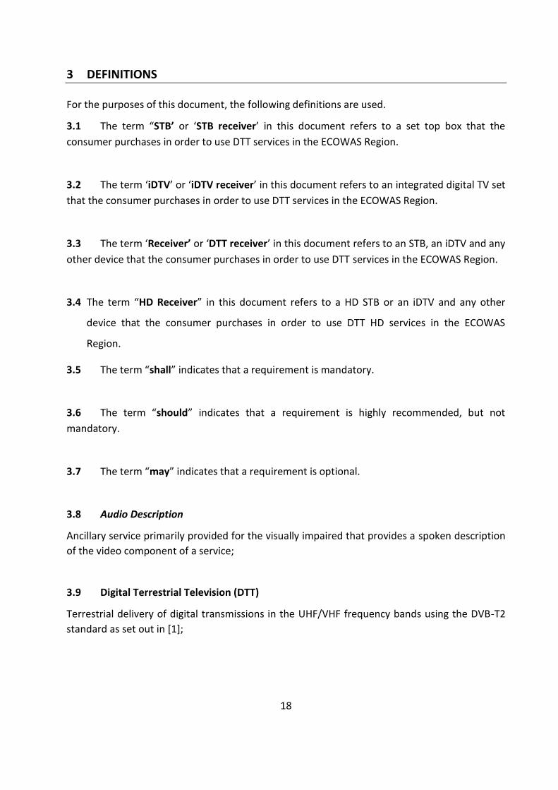
3 DEFINITIONS
For the purposes of this document, the following definitions are used.
3.1 The term “STB’ or ‘STB receiver’ in this document refers to a set top box that the consumer purchases in order to use DTT services in the ECOWAS Region.
3.2 The term ‘iDTV’ or ‘iDTV receiver’ in this document refers to an integrated digital TV set that the consumer purchases in order to use DTT services in the ECOWAS Region.
3.3 The term ‘Receiver’ or ‘DTT receiver’ in this document refers to an STB, an iDTV and any other device that the consumer purchases in order to use DTT services in the ECOWAS Region.
3.4 The term “HD Receiver” in this document refers to a HD STB or an iDTV and any other
device that the consumer purchases in order to use DTT HD services in the ECOWAS
Region.
3.5 The term “shall” indicates that a requirement is mandatory.
3.6 The term “should” indicates that a requirement is highly recommended, but not mandatory.
3.7 The term “may” indicates that a requirement is optional.
3.8 Audio Description
Ancillary service primarily provided for the visually impaired that provides a spoken description of the video component of a service;
3.9 Digital Terrestrial Television (DTT)
Terrestrial delivery of digital transmissions in the UHF/VHF frequency bands using the DVB-T2 standard as set out in [1];
19
3.10 Free-to-Air (FTA)
Service which is broadcast unencrypted or in clear and capable of being received without payment of subscription fees;
3.11 Multiplex (MUX)
Group of digital terrestrial television or audio programme channels or data services that are combined together into one output signal for broadcast;
3.12 Private Data Stream
DVB data stream designed for a specific application which is ignored by other DVB decoders that are not designed to use the data.
3.13 Analogue Systems
The Analogue System is used in Ghana is PAL B/G.
20
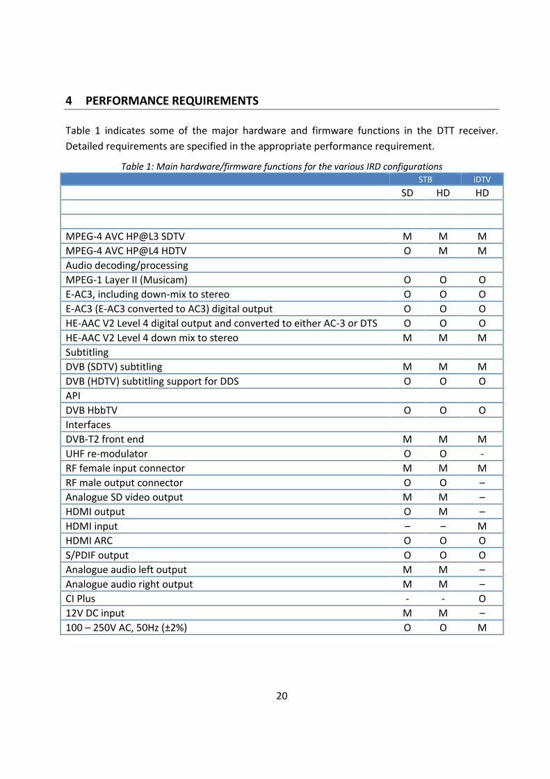
4 PERFORMANCE REQUIREMENTS
Table 1 indicates some of the major hardware and firmware functions in the DTT receiver. Detailed requirements are specified in the appropriate performance requirement.
Table 1: Main hardware/firmware functions for the various IRD configurations STB iDTV SD HD HD MPEG-4 AVC HP@L3 SDTV M M M MPEG-4 AVC HP@L4 HDTV O M M Audio decoding/processing MPEG-1 Layer II (Musicam) O O O E-AC3, including down-mix to stereo O O O E-AC3 (E-AC3 converted to AC3) digital output O O O HE-AAC V2 Level 4 digital output and converted to either AC-3 or DTS O O O HE-AAC V2 Level 4 down mix to stereo M M M Subtitling DVB (SDTV) subtitling M M M DVB (HDTV) subtitling support for DDS O O O API DVB HbbTV O O O Interfaces DVB-T2 front end M M M UHF re-modulator O O - RF female input connector M M M RF male output connector O O – Analogue SD video output M M – HDMI output O M – HDMI input – – M HDMI ARC O O O S/PDIF output O O O Analogue audio left output M M – Analogue audio right output M M – CI Plus - - O 12V DC input M M – 100 – 250V AC, 50Hz (±2%) O O M
21
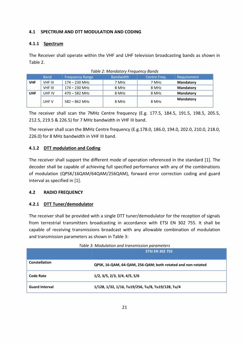
4.1 SPECTRUM AND DTT MODULATION AND CODING
4.1.1 Spectrum
The Receiver shall operate within the VHF and UHF television broadcasting bands as shown in Table 2.
Table 2: Mandatory Frequency Bands Band Frequency Range Bandwidth Centre Freq. Requirement VHF VHF III 174 – 230 MHz 7 MHz 7 MHz Mandatory
VHF III 174 – 230 MHz 8 MHz 8 MHz Mandatory UHF UHF IV 470 – 582 MHz 8 MHz 8 MHz Mandatory
UHF V 582 – 862 MHz 8 MHz 8 MHz Mandatory
The receiver shall scan the 7MHz Centre frequency (E.g. 177.5, 184.5, 191.5, 198.5, 205.5, 212.5, 219.5 & 226.5) for 7 MHz bandwidth in VHF III band.
The receiver shall scan the 8MHz Centre frequency (E.g.178.0, 186.0, 194.0, 202.0, 210.0, 218.0, 226.0) for 8 MHz bandwidth in VHF III band.
4.1.2 DTT modulation and Coding
The receiver shall support the different mode of operation referenced in the standard [1]. The decoder shall be capable of achieving full specified performance with any of the combinations of modulation (QPSK/16QAM/64QAM/256QAM), forward error correction coding and guard interval as specified in [1].
4.2 RADIO FREQUENCY
4.2.1 DTT Tuner/demodulator
The receiver shall be provided with a single DTT tuner/demodulator for the reception of signals from terrestrial transmitters broadcasting in accordance with ETSI EN 302 755. It shall be capable of receiving transmissions broadcast with any allowable combination of modulation and transmission parameters as shown in Table 3:
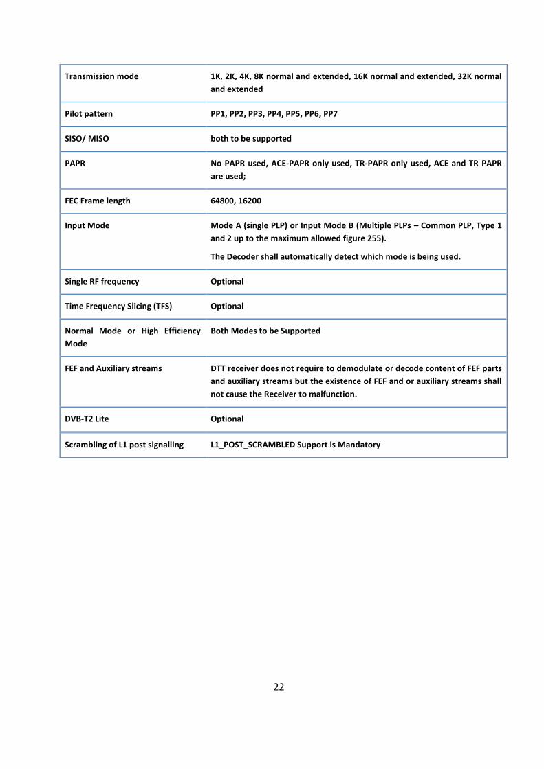
Table 3: Modulation and transmission parameters
ETSI EN 302 755
Constellation QPSK, 16-QAM, 64-QAM, 256-QAM; both rotated and non-rotated
Code Rate 1/2, 3/5, 2/3, 3/4, 4/5, 5/6
Guard Interval 1/128, 1/32, 1/16, Tu19/256, Tu/8, Tu19/128, Tu/4
22
Transmission mode 1K, 2K, 4K, 8K normal and extended, 16K normal and extended, 32K normal and extended
Pilot pattern PP1, PP2, PP3, PP4, PP5, PP6, PP7
SISO/ MISO both to be supported
PAPR No PAPR used, ACE-PAPR only used, TR-PAPR only used, ACE and TR PAPR are used;
FEC Frame length 64800, 16200
Input Mode Mode A (single PLP) or Input Mode B (Multiple PLPs – Common PLP, Type 1 and 2 up to the maximum allowed figure 255).
The Decoder shall automatically detect which mode is being used.
Single RF frequency Optional
Time Frequency Slicing (TFS) Optional
Normal Mode or High Efficiency Mode
Both Modes to be Supported
FEF and Auxiliary streams DTT receiver does not require to demodulate or decode content of FEF parts and auxiliary streams but the existence of FEF and or auxiliary streams shall not cause the Receiver to malfunction.
DVB-T2 Lite Optional
Scrambling of L1 post signalling L1_POST_SCRAMBLED Support is Mandatory
23
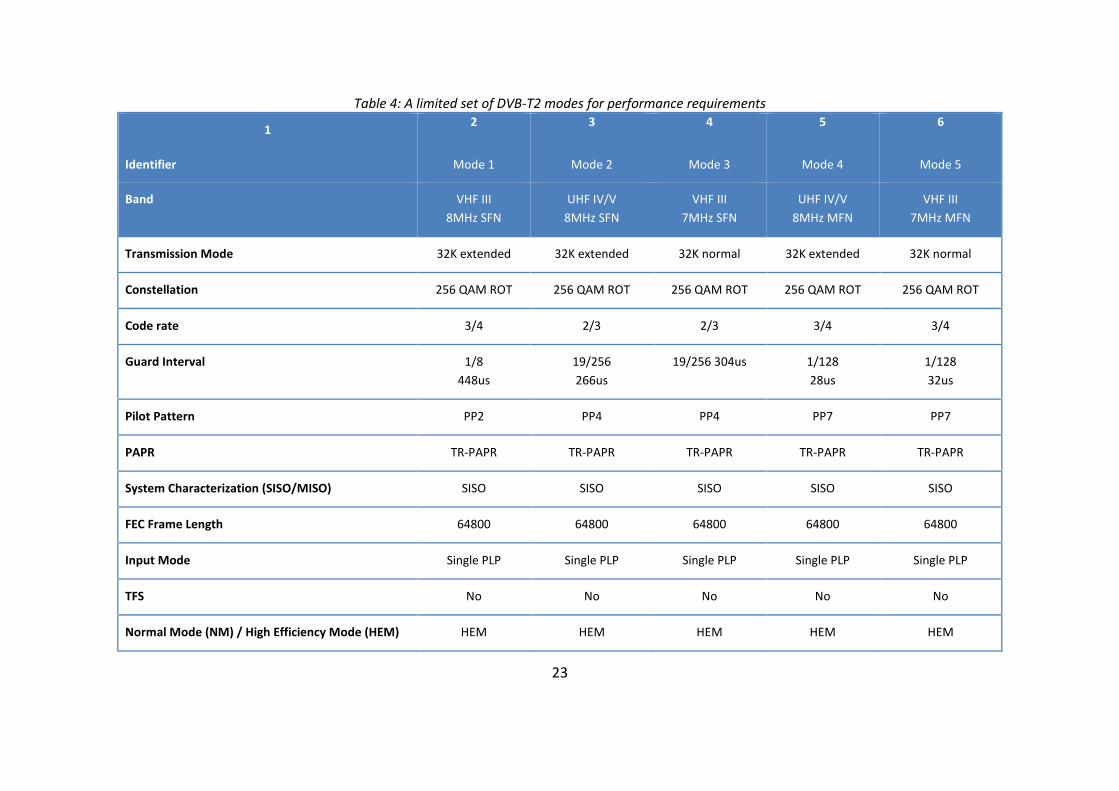
Table 4: A limited set of DVB-T2 modes for performance requirements
1 2 3 4 5 6
Identifier Mode 1 Mode 2 Mode 3 Mode 4 Mode 5
Band VHF III 8MHz SFN
UHF IV/V 8MHz SFN
VHF III 7MHz SFN
UHF IV/V 8MHz MFN
VHF III 7MHz MFN
Transmission Mode 32K extended 32K extended 32K normal 32K extended 32K normal
Constellation 256 QAM ROT 256 QAM ROT 256 QAM ROT 256 QAM ROT 256 QAM ROT
Code rate 3/4 2/3 2/3 3/4 3/4
Guard Interval 1/8 448us
19/256 266us
19/256 304us 1/128 28us
1/128 32us
Pilot Pattern PP2 PP4 PP4 PP7 PP7
PAPR TR-PAPR TR-PAPR TR-PAPR TR-PAPR TR-PAPR
System Characterization (SISO/MISO) SISO SISO SISO SISO SISO
FEC Frame Length 64800 64800 64800 64800 64800
Input Mode Single PLP Single PLP Single PLP Single PLP Single PLP
TFS No No No No No
Normal Mode (NM) / High Efficiency Mode (HEM) HEM HEM HEM HEM HEM
24
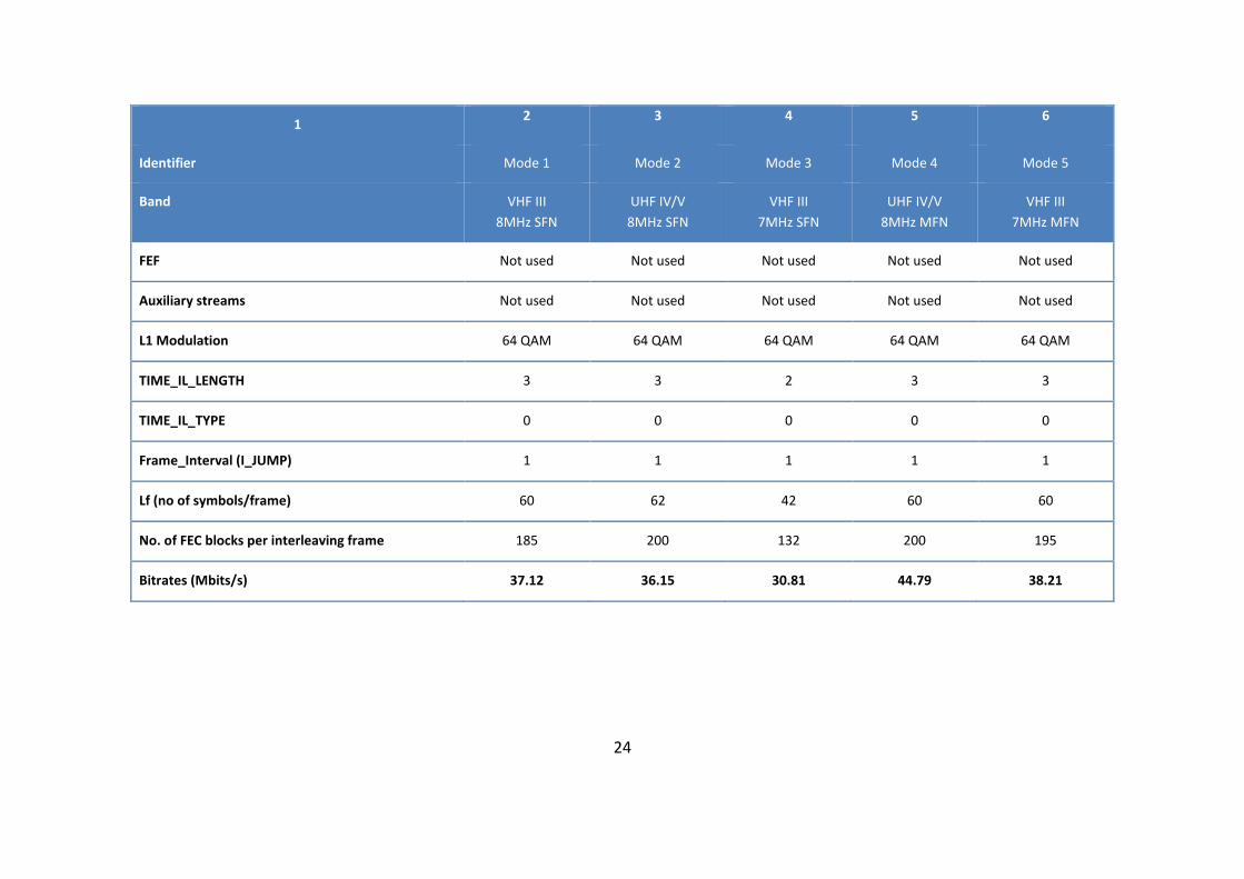
1 2 3 4 5 6
Identifier Mode 1 Mode 2 Mode 3 Mode 4 Mode 5
Band VHF III 8MHz SFN
UHF IV/V 8MHz SFN
VHF III 7MHz SFN
UHF IV/V 8MHz MFN
VHF III 7MHz MFN
FEF Not used Not used Not used Not used Not used
Auxiliary streams Not used Not used Not used Not used Not used
L1 Modulation 64 QAM 64 QAM 64 QAM 64 QAM 64 QAM
TIME_IL_LENGTH 3 3 2 3 3
TIME_IL_TYPE 0 0 0 0 0
Frame_Interval (I_JUMP) 1 1 1 1 1
Lf (no of symbols/frame) 60 62 42 60 60
No. of FEC blocks per interleaving frame 185 200 132 200 195
Bitrates (Mbits/s) 37.12 36.15 30.81 44.79 38.21
25
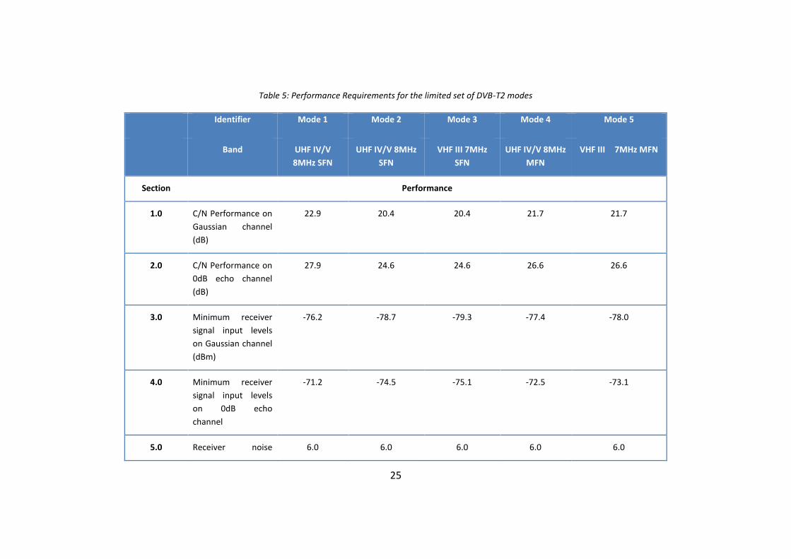
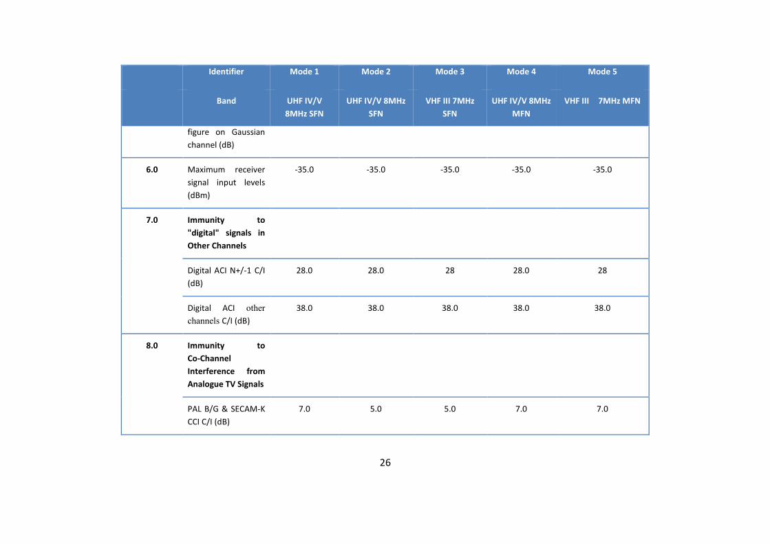
Table 5: Performance Requirements for the limited set of DVB-T2 modes
Identifier Mode 1 Mode 2 Mode 3 Mode 4 Mode 5
Band UHF IV/V 8MHz SFN
UHF IV/V 8MHz SFN
VHF III 7MHz SFN
UHF IV/V 8MHz MFN
VHF III 7MHz MFN
Section Performance
1.0 C/N Performance on Gaussian channel (dB)
22.9 20.4 20.4 21.7 21.7
2.0 C/N Performance on 0dB echo channel (dB)
27.9 24.6 24.6 26.6 26.6
3.0 Minimum receiver signal input levels on Gaussian channel (dBm)
-76.2 -78.7 -79.3 -77.4 -78.0
4.0 Minimum receiver signal input levels on 0dB echo channel
-71.2 -74.5 -75.1 -72.5 -73.1
5.0 Receiver noise 6.0 6.0 6.0 6.0 6.0
26
Identifier Mode 1 Mode 2 Mode 3 Mode 4 Mode 5
Band UHF IV/V 8MHz SFN
UHF IV/V 8MHz SFN
VHF III 7MHz SFN
UHF IV/V 8MHz MFN
VHF III 7MHz MFN
figure on Gaussian channel (dB)
6.0 Maximum receiver signal input levels (dBm)
-35.0 -35.0 -35.0 -35.0 -35.0
7.0 Immunity to "digital" signals in Other Channels
Digital ACI N+/-1 C/I (dB)
28.0 28.0 28 28.0 28
Digital ACI other channels C/I (dB)
38.0 38.0 38.0 38.0 38.0
8.0 Immunity to Co-Channel Interference from Analogue TV Signals
PAL B/G & SECAM-K CCI C/I (dB)
7.0 5.0 5.0 7.0 7.0

27
Identifier Mode 1 Mode 2 Mode 3 Mode 4 Mode 5
Band UHF IV/V 8MHz SFN
UHF IV/V 8MHz SFN
VHF III 7MHz SFN
UHF IV/V 8MHz MFN
VHF III 7MHz MFN
9.0 Immunity to Adjacent Channel Interference From Analogue TV Signals
PAL B/G & SECAM-K ACI C/I N+/-1 (dB)
33.0 33.0 33.0 Note 4 33.0 33.0 Note 4
PAL B/G & SECAM-K ACI other channels C/I (dB)
40.0 40.0 40.0 40.0 40.0
10.0 Performance in Time-Varying Channels 10Hz doppler (5Hz after AFC) 20μs 0dB echo
3 dB 3 dB 3 dB 3 dB 3 dB
11.0 Synchronisation for varying echo power levels in SFN (dB)
31.0 28.1 28.1 31.0 31.0
12.0 C/(N+I) Performance in Single Frequency Networks for more
27.9 24.6 24.6 26.6 26.6
28
Identifier Mode 1 Mode 2 Mode 3 Mode 4 Mode 5
Band UHF IV/V 8MHz SFN
UHF IV/V 8MHz SFN
VHF III 7MHz SFN
UHF IV/V 8MHz MFN
VHF III 7MHz MFN
than one echo (dB)
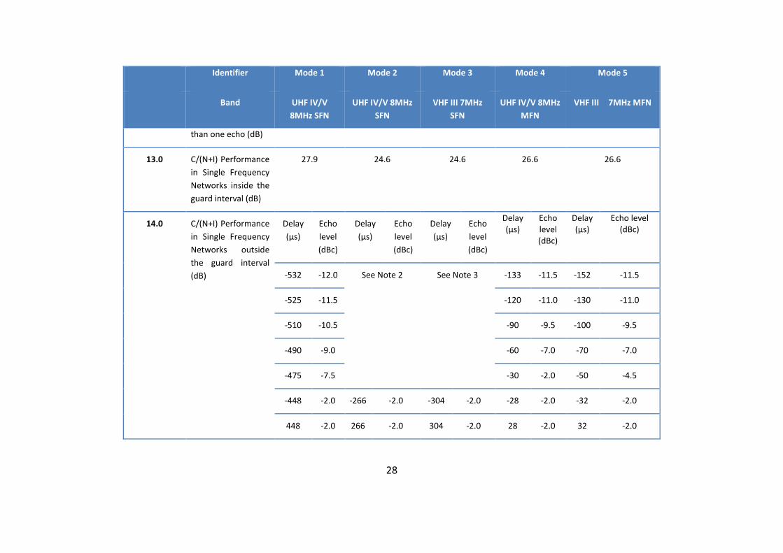
13.0 C/(N+I) Performance in Single Frequency Networks inside the guard interval (dB)
27.9 24.6 24.6 26.6 26.6
14.0 C/(N+I) Performance in Single Frequency Networks outside the guard interval (dB)
Delay (μs)
Echo level (dBc)
Delay (μs)
Echo level (dBc)
Delay (μs)
Echo level (dBc)
Delay (μs)
Echo level (dBc)
Delay (μs)
Echo level (dBc)
-532 -12.0 See Note 2 See Note 3 -133 -11.5 -152 -11.5
-525 -11.5 -120 -11.0 -130 -11.0
-510 -10.5 -90 -9.5 -100 -9.5
-490 -9.0 -60 -7.0 -70 -7.0
-475 -7.5 -30 -2.0 -50 -4.5
-448 -2.0 -266 -2.0 -304 -2.0 -28 -2.0 -32 -2.0
448 -2.0 266 -2.0 304 -2.0 28 -2.0 32 -2.0
29
Identifier Mode 1 Mode 2 Mode 3 Mode 4 Mode 5
Band UHF IV/V 8MHz SFN
UHF IV/V 8MHz SFN
VHF III 7MHz SFN
UHF IV/V 8MHz MFN
VHF III 7MHz MFN
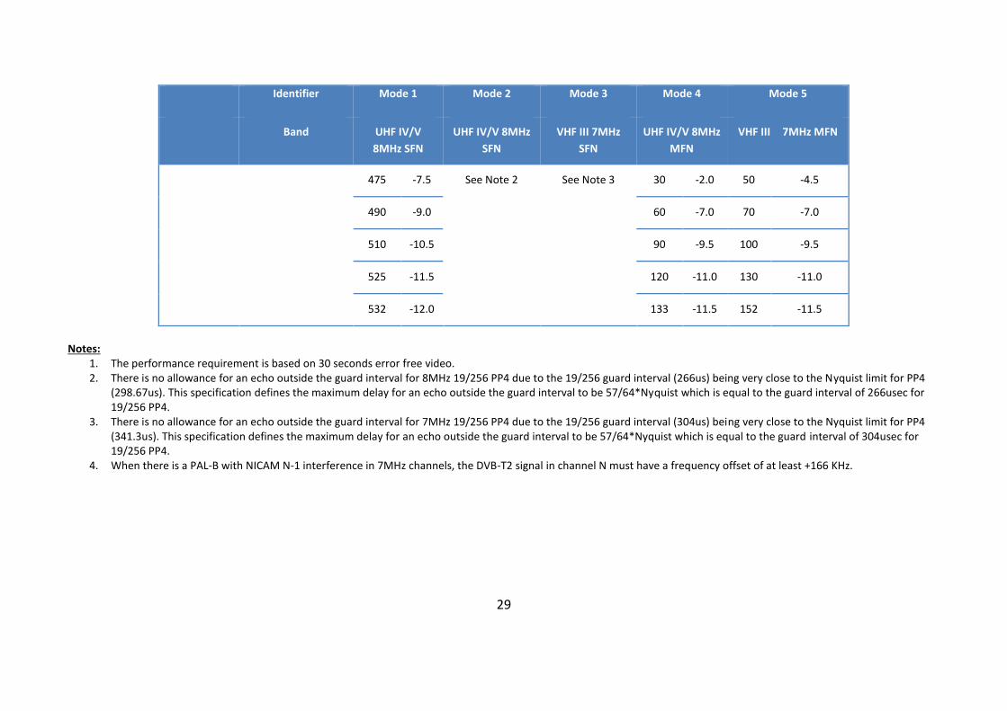
475 -7.5 See Note 2 See Note 3 30 -2.0 50 -4.5
490 -9.0 60 -7.0 70 -7.0
510 -10.5 90 -9.5 100 -9.5
525 -11.5 120 -11.0 130 -11.0
532 -12.0 133 -11.5 152 -11.5
Notes:
1. The performance requirement is based on 30 seconds error free video. 2. There is no allowance for an echo outside the guard interval for 8MHz 19/256 PP4 due to the 19/256 guard interval (266us) being very close to the Nyquist limit for PP4
(298.67us). This specification defines the maximum delay for an echo outside the guard interval to be 57/64*Nyquist which is equal to the guard interval of 266usec for 19/256 PP4.
3. There is no allowance for an echo outside the guard interval for 7MHz 19/256 PP4 due to the 19/256 guard interval (304us) being very close to the Nyquist limit for PP4 (341.3us). This specification defines the maximum delay for an echo outside the guard interval to be 57/64*Nyquist which is equal to the guard interval of 304usec for 19/256 PP4.
4. When there is a PAL-B with NICAM N-1 interference in 7MHz channels, the DVB-T2 signal in channel N must have a frequency offset of at least +166 KHz.
30
4.2.2 Tuning
General
The Decoder shall ignore all services originating from any non-DTT sources, such as DVB-H services, to avoid consumer confusion. Portable/handheld receivers should not ignore DVB-H services.
Automatic tuning
The DTT receiver shall be capable of performing automatic tuning over the frequency ranges indicated in Table 2: Mandatory Frequency Bands, to find all the multiplexes and services received in the complete frequency range.
The Receiver shall automatically detect which mode is being used (Refer to 4.2.1).
When receiving a DVB-T2 signal with Multiple PLP (i.e. Mode B), the Receiver shall analyse and interrogate the SI information per PLP.
The decoder shall display a given service only once in the service list (so avoiding duplicates of the same service), even if this service (i.e. same path comprising original network identifier, transport stream identifier and service identifier) is received from more than one transmitter. In such a case, the service emanating from the transmission with the highest quality (as defined by signal strength and signal quality) shall be the one chosen to be entered into the service list.
Manual tuning
In addition to automatic tuning, the Receiver decoder shall be capable of performing manual tuning where the channel number or frequency (or both) is entered by the viewer. The decoder shall tune to the channel entered by the viewer, search all available DTT modes and add any new services.
4.2.3 Response to changes in modulation
The DTT receiver shall recover from changes in modulation parameters and output an error free TS. This shall take less than one second for any change. The DTT receiver decoder tuned to a DVB-T2 transmission shall automatically recover from changes in P1, L1 pre-signalling data and L1 post signalling.
An error-free TS shall be available within five seconds for any P1 and/or L1 pre-signalling change. An error-free TS shall be output within five seconds for any L1 post-signalling FEF change and within two seconds for any other L1 post-signalling change.
31
4.2.4 Bypass support for STB
The path from RF input to RF output shall allow RF bypass independently of the operational or stand-by status of the STB decoder, so that connected equipment (e.g. a TV set) can continue to operate.
The RF bypass gain shall be in the range −1 dB to +3 dB over the frequency ranges in Table 2.
4.2.5 UHF re-modulator for STBs
STB receivers may provide a UHF re-modulated output for use with Analog Systems, listed in section 3.13, and it shall:
a) modulate the decoded baseband signal onto Analog Systems, listed in section 3.13, in accordance with [16], except that dual side bands shall be allowed;
b) have a peak signal level of 3 mV nominal across 75 Ω (−39 dBm); c) have a return loss at the output of less than 6 dB; d) be tunable from 470 MHz to 862 MHz; e) be preset at the factory to channel 63; f) support Analog Systems, listed in section 3.13, mono audio output, with a volume
control; g) have an audio FM deviation of 40 kHz ± 5 kHz at −12 dB full-scale transmitter output
setting (equivalent to +6 dBm studio sound level); h) have a vision to sound carrier ratio of 16 dB ± 4 dB; i) produce spurious output levels that do not exceed: 1) in band (as in Table 2): 12 dBμV max.; 2) out of band (30 MHz to 1 GHz, excluding in-band above): 43 dBμV max.; j) with the "RF out" terminated in 75 Ω, exhibit an output voltage leakage to the "RF
in" terminal of 36 dBµV max.
If the STB decoder provides a UHF re-modulator, the RF output shall be combined with an RF bypass facility that provides feeds for analogue TVs and VCRs. The second-order intermodulation at the RF output, measured in accordance with IEC 60728-5 with 85 dBµV input, shall be equal to or lower than −60 dBc.
4.2.6 Time Interleaving
The DTT receiver shall at least include time interleaving capability corresponding to the maximum time interleaving according to [1], i.e. 219+215 OFDM cells for a data PLP and its common PLP together.
32
4.3 DEMULTIPLEXING AND DECODING
4.3.1 Support of MPEG-4
The STB decoder shall support H.264 level 3, as defined in [14], decoding for standard definition display. iDTV receivers shall support H.264 level 4, as defined in [14], decoding for standard definition and high definition display.
The transport stream shall comply with [12], and the video profile level shall be Main profile level 3 in accordance with [14].
The DTT receiver shall support SD video resolution of 720 × 576.
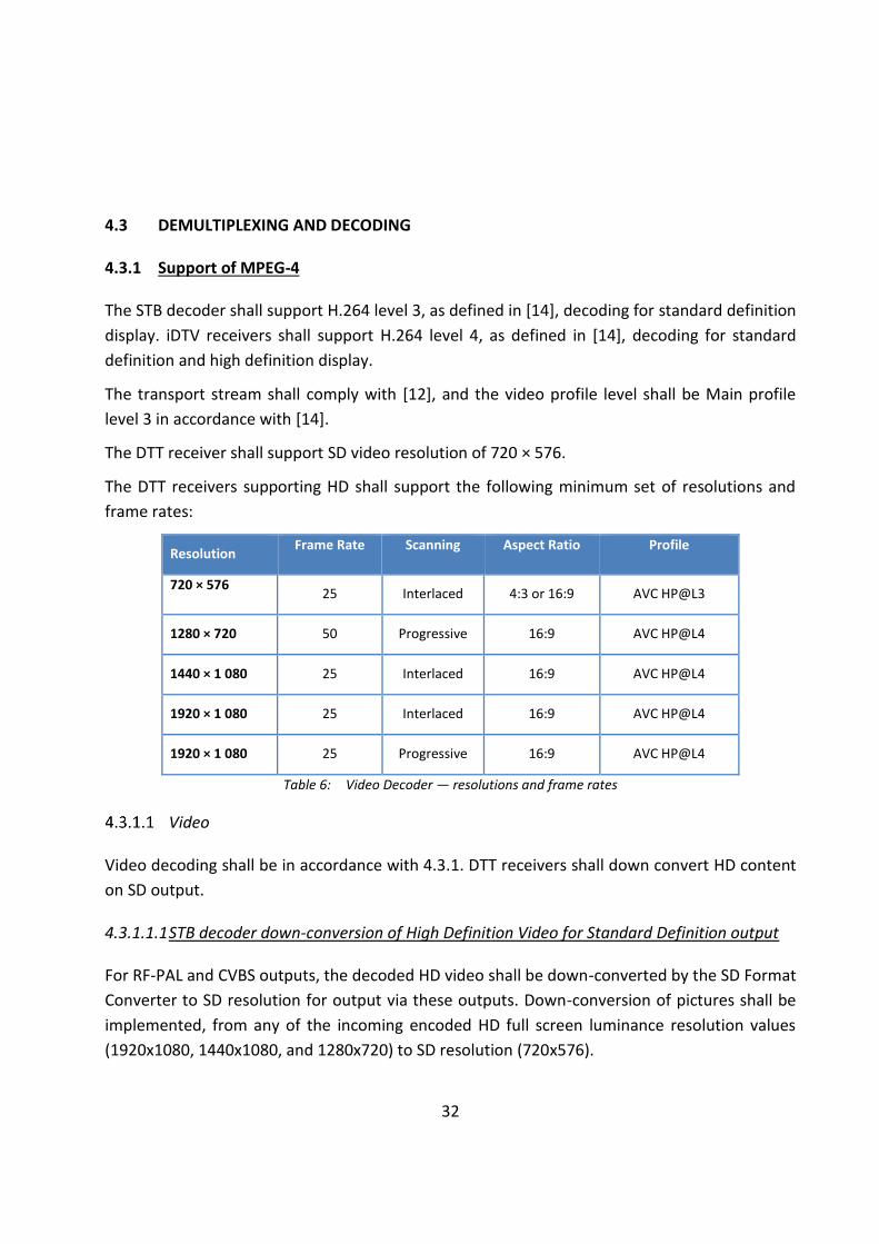
The DTT receivers supporting HD shall support the following minimum set of resolutions and frame rates:
Resolution Frame Rate Scanning Aspect Ratio Profile
720 × 576 25 Interlaced 4:3 or 16:9 AVC HP@L3
1280 × 720 50 Progressive 16:9 AVC HP@L4
1440 × 1 080 25 Interlaced 16:9 AVC HP@L4
1920 × 1 080 25 Interlaced 16:9 AVC HP@L4
1920 × 1 080 25 Progressive 16:9 AVC HP@L4
Table 6: Video Decoder — resolutions and frame rates
Video
Video decoding shall be in accordance with 4.3.1. DTT receivers shall down convert HD content on SD output.
4.3.1.1.1 STB decoder down-conversion of High Definition Video for Standard Definition output
For RF-PAL and CVBS outputs, the decoded HD video shall be down-converted by the SD Format Converter to SD resolution for output via these outputs. Down-conversion of pictures shall be implemented, from any of the incoming encoded HD full screen luminance resolution values (1920x1080, 1440x1080, and 1280x720) to SD resolution (720x576).

33
When down-converting any 1:1 pixel aspect ratio format (i.e. 1280x720 or 1920x1080) in the Decoder Composition Output to 720x576 resolution, the target shall be 702x576 pixels to be centered in the 720x576 grid with nine black pixels inserted as the start of the 720 pixel active line and nine pixels inserted as the end of the 720 pixel active line. The Down-converted HD video shall be displayed as 16:9 letter box on 4:3 displays. (Allowing centre cut would limit the safe area to 4:3 for HD production, hence not an allowed display option).
The SD Format Converter should apply appropriate re-interlacing (field mode integration re-interlacing). It shall process and output 720x576i25 in 4:3 frame aspect ratio or 16:9 frame aspect ratio video with colours according to the standards listed in Table 7.
Table 7: Video Decoder — colour frame aspect ratio
Active composition resolution in the “Decoder Composition Output” (Horizontal x Vertical)
Documentation for appropriate Colour Processing
Comments
720x576 ITU-R BT.1700 (replaces ITU-R BT.470 System B, G)
Note that 576 lines in both interlaced scan (576i) and progressive scan (576p) shall be processed and output with equal colour parameters.
4.3.1.1.2 Aspect Ratio
The DTT receiver shall support both 16:9 (widescreen) and 4:3 picture format changes, including support for the correct aspect ratio and use of the active format descriptor (AFD) as defined in [11].
For HD outputs, the Receiver shall be able to use the EDID information provided by the sink device to automatically determine the Receiver output.
The STB receiver shall provide an "Original Format" option, i.e. to output the same format as received if supported by the display, as indicated by the EDID information. If the received format is not supported, the STB Receiver should select the display mode providing the best possible video quality. This is to avoid the STB Receiver output to go black, if there is a mismatch between received format and display capabilities.
It shall also be possible to manually set the default output format from the STB Receiver to a fixed format.
For the down-converted SD format, the STB decoder shall support manual selection of the required aspect ratio.
34
For SD video and down converted HD video the combination of coded frame aspect ratio information plus the use of the AFD, embedded by the MPEG encoder into the video sequence header, shall provide the viewer with the following options:
a) 16:9 material on 4:3 displays : The decoder shall provide the following viewer options: 1) display the material as a 16:9 letterbox within a 4:3 frame; or 2) perform a 4:3 centre cut-out on the originating material and present this
full-frame within the 4:3 display. In this case the decoder shall support ‘pan and scan’ operation;
b) 4:3 material on 16:9 displays : The decoder shall provide "pillarboxing" of 4:3 material into a 16:9 frame, in order to maintain the correct aspect ratio of the originating material.
4.3.1.1.3 Support of still pictures
The DTT receiver shall be able to decode and display still pictures (frame), i.e. a video sequence that contains a single intra-coded picture. Such a video bit stream will cause the buffer to under-flow. In this situation, while the decoding process shall continue to examine the buffer, the display process associated with the decoder shall repeat the previously decoded picture until the normal operation of the buffer can resume.
Outputs for STBs
If the STB decoder uses a re-modulator, all Analog Systems, listed in section 3.13, modulated SD video and audio signal shall be presented as prescribed in 4.2.5.1 on a connector as defined in 4.11.3.
The STB decoder shall also provide a composite (CVBS) video output on a RCA socket as defined in 4.11.3. The composite video signal levels shall be in accordance with ISO / IEC 61938. For decoders supporting HD, the decoder shall derive a down-converted version for output via this interface as described in 4.3.2. The decoder shall provide a single HDMI output for HD content.
4.3.2 Audio
The STB Receiver shall support the possibility to adjust the audio-delay on the S/PDIF output (if available) up to 250 ms and it should be adjustable in 10 ms steps, as the STB Receiver may have several different user set-ups, resulting in different a/v delays; e.g. the STB Receiver may be connected to several types of external audio-amplifiers and the STB Receiver may be connected to several types of external screens.
General
The DTT receiver shall support decoding of HE-AAC v1 Level 4 and HE-AAC v2 Level 4 in accordance with [13] and [11].
35
The Dynamic Range Control tool as defined in Section 6.4.3 of [11] and the MPEG4 Audio ancillary Data as defined in Annex C.5 of [11] shall be supported with the exception of Presentation Mode as defined in C.5.4 of [11]. The support of Presentation Modes as defined in C.5.4 of [11] shall be optional. For SD STB receivers the decoded HE_AAC v2 Level 4 bit stream shall always be a down mix to stereo for the output. For SD STB receivers with HDMI interface may support pass through of the HE-AAC v2 Level 4 bit stream.
HD Receivers shall support decoding of HE-AAC v2 Level 4 bit streams. HD Receivers should support conversion of HE-AAC v2 Level 4 streams to either an AC-3 or DTS bit stream for output via S/PDIF or HDMI ARC. Pass through of the HE-AAC v2 Level 4 bit stream over S/PDIF or HDMI ARC may be supported.
HD Receivers should support decoding of E-AC-3 elementary streams. HD Receivers should also support conversion of E-AC-3 elementary streams to an AC-3 bitstream for output via HDMI (only STB) and S/PDIF. If this option is supported, the decoding and conversion of an E-AC-3 elementary stream shall conform to the requirements defined in ETSI TS 102 366 including annex E.
Support for decoding MPEG-1 Layer II (Musicam) is optional.
The decoder shall use the ISO 639 language descriptors to determine languages of audio service elements, handle dynamic changes and present audio service information.
Bit rate
HD Receivers should support decoding of E-AC-3 elementary streams encoded at bit rates of up to 3 024 kbit/s.
Sampling frequency
HD Receivers should support decoding of E-AC-3 elementary streams encoded at a sample rate of 48 kHz.
Audio Description
Receivers shall be capable to simultaneously decode the main program and an associated audio description stream both encoded with HE-AAC. The associated audio description stream shall contain only a mono signal and shall use the same sampling frequency as the main program. The mixing of the two streams shall be done according to ETSI TS 101 154 Annex E.
HD Receivers should be capable of simultaneously decoding two different programme elements (Main Audio and Audio Description) carried in two separate E-AC-3 elementary streams. Audio mode
36
The Audio Description HD decoder may be capable of decoding a single independent substream from an E-AC-3 elementary stream containing up to 5.1 channels of audio. The Audio Description HD decoder may be capable of outputting at least 2-channels of decoded PCM. The Audio Description HD decoder may support downmixing of E-AC-3 streams that contain more than 2 channels of audio.
4.3.2.4.1 Sampling frequency
The Audio Description HD decoder should support decoding of E-AC-3 sub streams and elementary streams encoded at a sample rate of 48 kHz. If the sample rate of the Audio Description service does not match the sample rate of the Main Audio service, the HD receiver may decode only the Main Audio service.
4.3.2.4.2 Substream support
Enhanced AC-3_Descriptor substreamN_flag shall always be set to 0b0.
4.3.2.4.3 Mixing metadata
The Audio Description HD decoder should support extraction of mixing metadata from the E-AC-3 bitstream and delivery of this mixing metadata to an audio mixing component within the receiver. The AD_Descriptor, if present, shall be ignored.
4.3.2.4.4 Audio Description synchronization requirements.
If audio access units from two audio services which are to be simultaneously decoded have identical values of PTS indicated in their corresponding PES headers, then the corresponding audio access units shall be presented to the audio decoder for simultaneous synchronous decoding. Synchronous decoding means that for corresponding audio frames (access units), corresponding audio samples are presented at the identical time.
If the PTS values do not match (indicating that the audio encoding was not frame synchronous) then the audio frames (access units) of the main audio service may be presented to the audio decoder for decoding and presentation at the time indicated by the PTS. An audio description service, which is being simultaneously decoded, may have its audio frames (access units), which are in closest time alignment (as indicated by the PTS) to those of the main service being decoded, presented to the audio decoder for simultaneous decoding. In this case the associated service may be reproduced out of sync by as much as 1/2 of a video frame.
Mono-audio for STB receivers
37
There shall be a configurable option in the On-screen Menu to replace the analogue Stereo Left signal output via one of the RCA sockets with a derived analogue Mono feed.
Audio Outputs
4.3.2.6.1 HDMI outputs
HD STB receiver shall include an HDMI output, as described in section 4.11.3, and the following audio-specific requirements shall be implemented:
a) HD STB receivers shall determine the audio decoding capability of a connected HDMI sink device by reading the E-EDID structure of the sink device. b) If the HDMI sink device indicates support for HE-AAC decoding, the HD STB receiver may output the HE-AAC elementary stream directly to the HDMI sink device. c) If the HDMI sink device indicates support for E-AC-3 decoding, the HD STB receiver may output the E-AC-3 elementary stream directly to the HDMI sink device. d) If the HDMI sink device does not indicate support for HE-AAC decoding, but supports AC-3 or DTS decoding, the HD STB receiver may convert the HE-AAC bit stream to an AC-3 or DTS bit stream prior to HDMI output. e) If the HDMI sink device does not indicate support for E-AC-3 decoding, but supports AC-3 decoding, the HD STB receiver may convert the E-AC-3 elementary stream to an AC-3 bitstream prior to HDMI output. f) If the sink device does not indicate support for either HE-AAC, AC-3 or E-AC-3 decoding, or the user has selected “stereo” output via the on screen menu, the HD STB receiver may decode the elementary stream to stereo PCM prior to HDMI output.
4.3.2.6.2 HDMI inputs with ARC output
If reading E-EDID of the HDMI sink device is supported then the following audio-specific requirements should be implemented:
a) If the HDMI sink device indicates support for HE-AAC decoding, the HD receiver may output the HE-AAC elementary stream directly to the HDMI sink device over the ARC
b) If the HDMI sink device indicates support for E-AC-3 decoding, the HD receiver may output the E-AC-3 elementary stream directly to the HDMI sink device over the ARC c) If the HDMI sink device does not indicate support for HE-AAC decoding, but supports AC-3 or DTS decoding, the HD receiver may convert the HE-AAC bit stream to an AC-3 or DTS bit stream prior to the transport over HDMI ARC d) If the HDMI sink device does not indicate support for E-AC-3 decoding, but supports AC-3 decoding, the HD receiver may convert the E-AC-3 elementary stream to an AC-3 bit stream prior to the transport over HDMI ARC e) If the sink device does not indicate support for either HE-AAC, AC-3 or E-AC-3 decoding, or the user has selected “stereo” output via the on screen menu, the HD receiver may decode the elementary stream to stereo PCM prior to transport over HDMI ARC.

38
If reading E-EDID of the HDMI sink device is not supported then the following audio-specific requirements shall be implemented:
a) Convert the E-AC-3 elementary stream to AC-3 prior to HDMI ARC output. (optional) b) Convert the HE-AAC bit stream to either AC-3 or DTS prior to HDMI ARC output. (optional) c) Pass through the HE-AAC bit stream on HDMI ARC output. (optional) d) If the user has selected “stereo” output via the on screen menu, the HD receiver shall decode the elementary stream to stereo PCM prior to HDMI ARC output.
4.3.2.6.3 S/PDIF Audio outputs
HD STB receiver may include an S/PDIF output, as described in section 4.11.3 and the following requirements shall be implemented:
a) Convert the E-AC-3 elementary stream to AC-3 prior to S/PDIF output. (optional) b) Pass through the HE-AAC bit stream. (optional) c) If the user has selected “stereo” output via the on screen menu, the HD receiver shall
decode the elementary stream to stereo PCM prior to S/PDIF output.
HD receiver may include an S/PDIF output, as described in section 4.11.3 and the following requirements shall be implemented:
a) Convert the E-AC-3 elementary stream to AC-3 prior to S/PDIF output. (optional) b) Convert the HE-AAC bit stream to either AC-3 or DTS prior to S/PDIF output. (optional) c) Pass through the HE-AAC bit stream. (optional) d) If the user has selected “stereo” output via the on screen menu, the STB receiver shall
decode the elementary stream to stereo PCM prior to S/PDIF output.
4.3.2.6.4 Analogue audio outputs
STB receiver shall include an analogue audio output, as described in section 4.11.3 and decode the audio elementary stream prior to analogue audio output.
4.4 SUBTITLING
The DTT receiver shall be capable of displaying subtitles for the hearing impaired in accordance with [9].
The decoder shall be capable of overlaying the subtitle text on the picture. The subtitles for the hearing impaired may differ from the normal subtitles by the amount of text displayed per second, which is controlled by the broadcasted content.
39
The Receiver shall be capable of displaying subtitles in English, French, Portuguese and major languages spoken in ECOWAS Region. These languages can be provided by State Member if needs.
The Receiver shall provide the option of Enabling or Disabling the displaying of subtitles. When enabled, subtitles will automatically be displayed. When disabled, the decoder shall allow manual selection from the available list of broadcasted subtitle services. The Receiver shall allow the user to configure the preferred first and second language subtitle services, which will be automatically displayed when available. Should neither be available, the first available subtitle language may be presented. The decoder shall provide the option of disabling the language presented, or of selecting another available language.
The presence of subtitle services shall be indicated by a subtitle icon on the Now and Next Banner. When the subtitle or languages button is selected on the remote control unit, the list of available subtitle languages shall be displayed and the user can select his preference.
The Receiver shall be capable of displaying subtitling and interactive graphics simultaneously, where available and supported by the receiver.
4.5 TELETEXT
Teletext services shall be provided in accordance with ETSI EN 300 472.
4.6 SERVICE INFORMATION (SI) AND PROGRAM-SPECIFIC INFORMATION (PSI)
4.6.1 Service information tables
The general implementation of SI and PSI shall be in accordance with [6] and [7].
The DTT receiver shall be able to process the PSI/SI tables. The following “Actual” tables shall be Mandatory:- NIT, SDT, EIT, TDT.
AIT shall be mandatory for receivers that support Interactivity. EIT shall be mandatory for "Other" transport streams.
4.6.2 Networks and bouquets
It is anticipated that bouquets will be allocated on a regional basis. Services will be broadcast on both a national and regional basis with the SI tables containing information on all events.
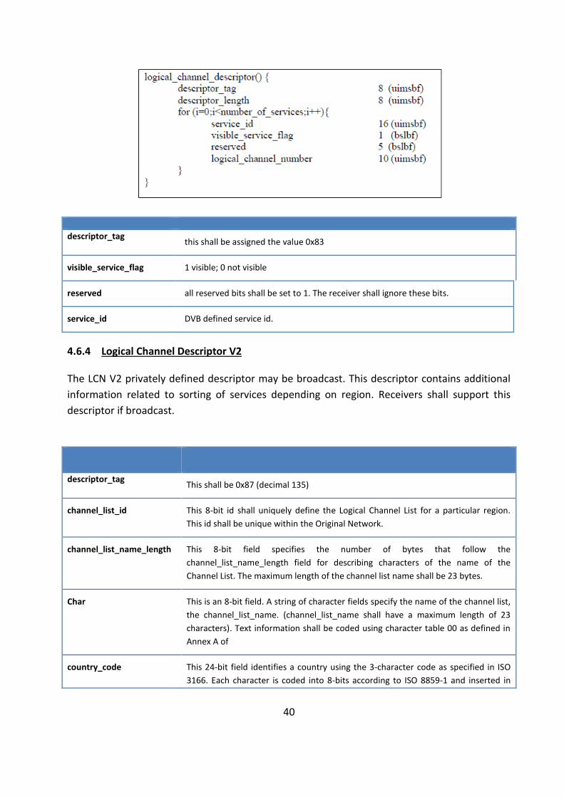
4.6.3 Logical Channel Number Descriptor
LCN information shall be broadcasted via a privately defined LCN descriptor as outlined below. This descriptor shall be broadcasted in the TS Loop of the NIT on all multiplexes.
40
descriptor_tag this shall be assigned the value 0x83
visible_service_flag 1 visible; 0 not visible
reserved all reserved bits shall be set to 1. The receiver shall ignore these bits.
service_id DVB defined service id.
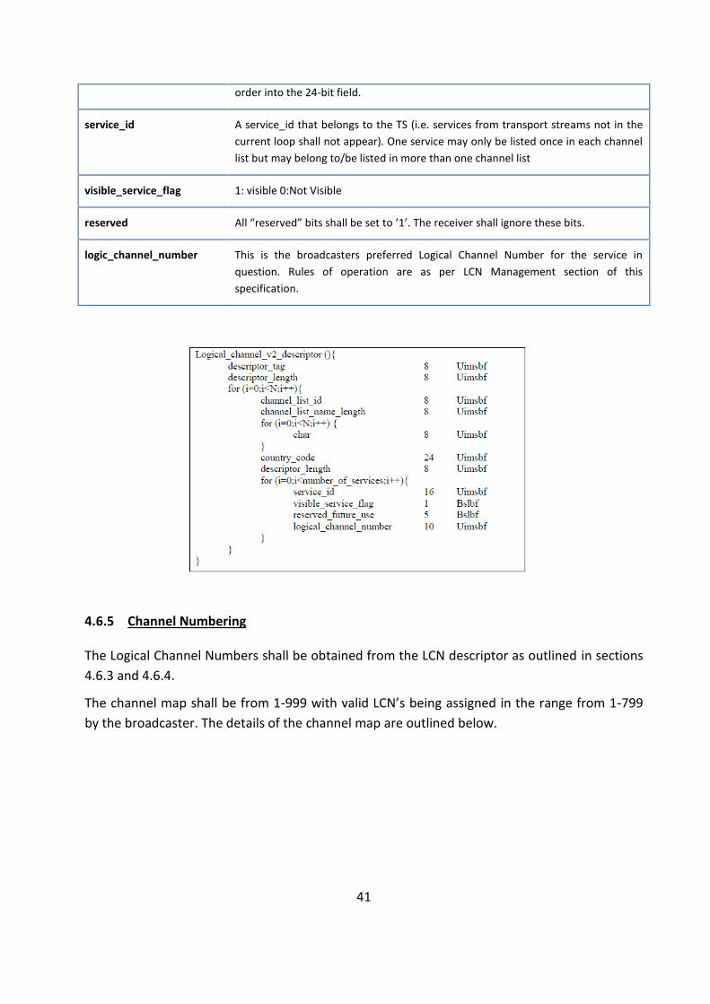
4.6.4 Logical Channel Descriptor V2
The LCN V2 privately defined descriptor may be broadcast. This descriptor contains additional information related to sorting of services depending on region. Receivers shall support this descriptor if broadcast.
descriptor_tag This shall be 0x87 (decimal 135)
channel_list_id This 8-bit id shall uniquely define the Logical Channel List for a particular region. This id shall be unique within the Original Network.
channel_list_name_length This 8-bit field specifies the number of bytes that follow the channel_list_name_length field for describing characters of the name of the Channel List. The maximum length of the channel list name shall be 23 bytes.
Char This is an 8-bit field. A string of character fields specify the name of the channel list, the channel_list_name. (channel_list_name shall have a maximum length of 23 characters). Text information shall be coded using character table 00 as defined in Annex A of
country_code This 24-bit field identifies a country using the 3-character code as specified in ISO 3166. Each character is coded into 8-bits according to ISO 8859-1 and inserted in
41
order into the 24-bit field.
service_id A service_id that belongs to the TS (i.e. services from transport streams not in the current loop shall not appear). One service may only be listed once in each channel list but may belong to/be listed in more than one channel list
visible_service_flag 1: visible 0:Not Visible
reserved All “reserved” bits shall be set to ’1’. The receiver shall ignore these bits.
logic_channel_number This is the broadcasters preferred Logical Channel Number for the service in question. Rules of operation are as per LCN Management section of this specification.
4.6.5 Channel Numbering
The Logical Channel Numbers shall be obtained from the LCN descriptor as outlined in sections 4.6.3 and 4.6.4.
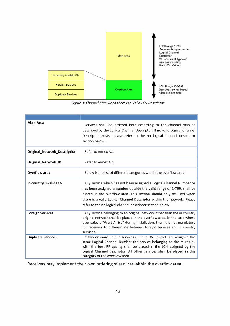
The channel map shall be from 1-999 with valid LCN’s being assigned in the range from 1-799 by the broadcaster. The details of the channel map are outlined below.
42
Figure 3: Channel Map when there is a Valid LCN Descriptor
Main Area Services shall be ordered here according to the channel map as
described by the Logical Channel Descriptor. If no valid Logical Channel Descriptor exists, please refer to the no logical channel descriptor section below.
Original_Network_Description Refer to Annex A.1
Original_Network_ID Refer to Annex A.1
Overflow area Below is the list of different categories within the overflow area.
In country invalid LCN Any service which has not been assigned a Logical Channel Number or has been assigned a number outside the valid range of 1-799, shall be placed in the overflow area. This section should only be used when there is a valid Logical Channel Descriptor within the network. Please refer to the no logical channel descriptor section below.
Foreign Services Any service belonging to an original network other than the in country original network shall be placed in the overflow area. In the case where user selects “West Africa” during installation, then it is not mandatory for receivers to differentiate between foreign services and in country services.
Duplicate Services If two or more unique services (unique DVB triplet) are assigned the same Logical Channel Number the service belonging to the multiplex with the best RF quality shall be placed in the LCN assigned by the Logical Channel descriptor. All other services shall be placed in this category of the overflow area.
Receivers may implement their own ordering of services within the overflow area.

43
When no logical channel descriptor is found within the in country Original Network, all in country services shall be assigned Logical Channel Numbers in any order sequential from 1 onwards.
Figure 4: Illustration of Channel Map when LCN descriptor is not broadcasted
Services from the original network of foreign countries shall be placed immediately after the last in country service. In the case where user selects “West Africa” during installation, then it is not mandatory for receivers to differentiate between foreign services and in country services.
When there are duplicate services (same DVB triplet) only the service from the multiplex with the best RF quality shall be visible to the user, the duplicate shall not be assigned a logical channel number.
Regional Broadcast Management
A regional multiplex might contain one or more services which have events that differ from one region to another.
The receiver shall decode the Logical Channel Descriptor Version 2 as outlined above.
During initial install, all channel lists for the country selected by the user shall be collated by the receiver. Once the scan is complete, if there is more than 1 valid channel list, the user shall be given a method to select a preferred list. The wording of the selection items presented to the user shall include the 23 character string broadcasted in the descriptor.
The receiver shall then order the services based on the selected channel list.
Service configuration
The DTT receiver shall automatically detect configuration changes such as service information, modulation and frequency, as well as the adding or the deleting of services, and shall amend its operation accordingly without user intervention or disruption to services.
NOTE: It is anticipated that the DTT service will include a dynamic element in terms of the use of available bandwidth.
44
EIT present/following, actual/other
Only EIT present/following (Now and Next) information shall be broadcast, including extended event information, for services carried in all DTT transport streams, i.e. EIT present/following including genre tables, parental control and series descriptor.
Time exclusive services
The DTT receiver may support the use of time exclusive services, i.e. where part of the multiplex capacity is used to support different services depending upon the time of the day. The services shall be shown within the relevant channel listings and users shall be able to select them as for normal services. During the time period when a service is not using the multiplex capacity (i.e. the service is inactive), the decoder may display a notification screen (the Placeholder) which will typically provide the service name and its hours of operation..
The decoder should provide seamless transitions between active and inactive states so that the user experiences the replacement of the Placeholder screen with the active service, and vice versa.
4.7 MEMORY
4.7.1. The DTT receiver shall have a minimum memory capacity of:
a) 8Mbytes Flash memory, b) 128 Mbytes RAM.
4.7.2. Settings and parameters, for example security-related data, shall be stored in non-volatile memory.
4.7.3. Manufacturers may emulate EEPROM in Flash in which case some parts of this data shall be enciphered in the NVRAM.
4.7.4. The memory specification has been chosen to allow for the lowest component price assuming the use of NAND Flash, but manufacturers are free to propose alternative technologies such as a hybrid solution making use of NOR and NAND Flash where these comply with the requirements of this standard.
4.8 GRAPHICS CAPABILITIES
4.8.1 Resolution
The colour resolution shall be at least 16 bits (4:4:4:4) and the DTT receiver shall include a look-up table capable of storing a minimum of 256 × 24-bit RGB colour/transparency entries.
4.8.2 Multiple display planes
45
The DTT receiver shall have three display planes as given in 4.8.2.2 to 4.8.2.4, each with the capability of blending with active video. A minimum of 16 individual transparency levels shall be supported.
Graphics plane ("front" plane) that supports full screen On-screen display information. The sizing of the graphics display plane shall be a 4:3 aspect ratio, regardless of the video aspect ratio.
Video plane, that supports a full screen MPEG video stream or still image.
Background plane ("back" plane), that comprises a single-colour (24-bit RGB) background with a default setting of black.
4.9 STANDBY OPERATION
4.9.1 Passive standby operation
Passive standby in STB receiver shall be provided and shall be the main standby mode, with the main CPU disabled but the RCU Rx function active and the re-modulator bypass active.
4.9.2 Active standby operation
In case it is not possible to provide a passive standby with the power requirements in 4.9.4(c), the DTT receiver shall provide an active standby state.
After selecting standby the STB receiver may remain in active standby for 5 min before switching to passive standby.
This mode shall support the downloading of data using DVB-SSU (including DTT receiver control information if this capability is installed) to the DTT receiver Flash memory.
4.9.3 Power-up times
The STB Receiver shall generate an on-screen message within 10s of the start of a reboot operation confirming that the decoder is powering up.
The following time limits shall apply to transitions in and out of standby operations:
a) DTT receiver Off to Service display: a maximum of 20s; b) Active Standby to Service display: a maximum of 5s; c) Passive Standby to Service display: a maximum of 10s.
4.9.4 Power consumption for STBs
The STB together with its power supply shall have the following maximum power consumption:
a) Normal Operation: 10 W; b) Standby (Active): 6 W;
46
c) Standby (Passive): 3 W.
NOTE These values will be reviewed to reduce energy consumption when technology permits.
4.10 POWER SUPPLY
The STB receiver shall be supplied complete with 100-250 V AC to 12V DC power supply unit where the nominal frequency shall be 50Hz with a fluctuation range between ±2%.
The mains supply power unit may, at the discretion of the manufacturer be incorporated in the receiver or alternatively be provided as an external module. Protection against overvoltage or under voltage, frequency variations and reversed polarity shall be incorporated.
A DC power supply of +5 V capable of supplying a maximum current of 100 mA suitable for powering an external antenna amplifier shall be available on the input RF connector of STB. The DC power supply should not degrade the performance of the RF input. The DC power supply shall be protected against short circuits. It shall be possible to switch on or off the DC power supply via a selection in the menu structure. The default at first-time initialization and resetting to factory default shall be the DC supply switched off.
4.11 INTERFACES
4.11.1 STB LED indications
4.11.1.1 Bi-colour LEDs
The STB receiver shall have a minimum of two bi-colour LEDs (LED #1 and LED #2) on the front panel.
The two LEDs shall be clearly distinguishable from each other either by their physical position (separation, left side LED and right side LED), or by means of a label.
LED #1 shall be defined as the Power LED on the left-hand side. LED #2 shall be defined as the Status LED on the right-hand side.
The colours of the Power LED shall be Red/Green.
The colours of the Status LED shall be Red/Green.
4.11.1.2 The Power LED — Red/Green
The Power LED indications shall be as follows:
Standby = Red; Operate = Green; Reception of RCU command = flashing single burst. 4.11.1.3 The Status LED — Red/Green
The Status LED indications in STB shall be as follows:

47
System boot/program search = flashing Green; Normal operation = continuous Green; Fault/no signal found = continuous Red; Software download in progress = flashing Red.
4.11.2 Controls
The following controls shall be provided on the front panel of STB receiver. iDTV may have the following controls at a place around the front panel that the user can operate easily:
x Program selector P+ and P−; x Volume selector V+ and V−; x Menu; x Ok; x Standby/On.
4.11.3 Connectors
The following connectors shall be used:
a) An RF input female connector that complies with IEC 61169-2 or IEC 611969-24 (type F). b) An RF output male connector that complies with IEC 61169-2 or IEC 611969-24 (type F)
for STB receiver. c) UHF re-modulated outputs for STB receivers [optional]. d) Colour-coded RCA sockets for composite (CVBS) video and stereo audio [output for STB,
input for iDTV]. e) A DC power jack of 9.5 mm in length, outside diameter (OD) of 5.5 mm, centre pin of 2.5
mm, and with the centre pin as +12 V and the outer contact as earth for STB receiver. f) A USB 2.0 port via a USB type A jack [optional]. g) HDMI input - type A [mandatory for iDTV] h) HDMI output – type A [optional for STB] i) S/PDIF output [optional] j) The use of a C8 AC power inlet in accordance with IEC 60320-1 for the power supply
built into the DTT receiver for STB receiver .
4.11.4 Identification
The decoder shall have an external label with the following information:
a) identification of the manufacturer or the supplier (or both); b) model number of the decoder; c) serial number of the decoder. d) Normative voltage and frequency.
The above items a, b &c shall also be available in the software of the DTT Receiver.
48
5 APPLICATIONS
5.1 HBBTV INTERACTIVE APPLICATION ENVIRONMENT
The DTT receiver may implement all mandatory requirements of [17].
5.2 ELECTRONIC PROGRAM GUIDE (EPG)
Receiver shall provide a programme guide. It is preferable that this uses data from the transmitted DVB EIT schedule tables. This is because these tables are continually updated by broadcasters to reflect schedule changes. If the source of the schedule data is EITschedule, acquisition shall be continuous and not dependent upon the reception of the first sections of any tables for acquisition to start. If a Receiver is unable to maintain continuous acquisition such that a section is missed, it should be acquired at the next available opportunity. Receiver shall concurrently acquire EIT schedule for all receivable services. When a receiver caches the EIT information, it should ensure that updates to the broadcast EIT tables are reflected in the cache within one cycle of the modified table. If an equivalent data source is used but is unavailable, the Receiver shall use EIT instead. An “equivalent data source” is defined to be a data source that provides sufficient information in a suitably timely manner to meet all of the mandatory requirements in this chapter.
The EPG display shall be available at all times (excluding standby) following initial acquisition.
5.2.1 EPG Scope and Accuracy
The Receiver shall display a minimum of 8 days of schedule data in the EPG (subject to the purging of data for past events by the receiver). This can be derived from the EITschedule information (recommended because of its accuracy) or from an alternative source providing an equivalent level of information. When possible, the accuracy of the EPG should be improved further by use of the EITp/f information.
Note: Broadcasters may delete some or all of the current day's past events during EITschedule updates. Consequently, Receiver should not rely on the information about past events in the broadcast schedule when displaying the EPG.
5.2.2 EPG Updating
When the user accesses the EPG, it shall be displayed regardless of the state of the receiver’s schedule database (for example, database is partially populated in the minutes after power-on). In normal operation, the Receiver shall maintain the full EPG up to date and be able to display the full EPG within 10 seconds of selection. The Receiver shall display EPG information as soon as it is received without requiring user interaction to update the display.
49
5.2.3 EPG and Local time
The EPG shall always display events with the correct local time offset which applies at the time for which the event is billed.
5.3 LANGUAGES AND FONTS
The Languages and Fonts as described in section 4.10c)2 shall be support if received as any string in SI/PSI.
5.4 SECURE DOWNLOADS AND UPDATES
Support for downloads
The DTT receiver shall support over-the-air downloads of authorized software.
Over-the-air updates
Over-the-air updates shall use the DVB System Software Update mechanism (DVB-SSU Simple profile) specified in [10].
Each software release has a unique model or version reference which shall be used by the Receiver to establish whether it is to be downloaded. The DTT receiver shall only respond to updates that contain this unique identifier. In particular, the Receiver shall not respond to updates targeted at other Receiver models produced by the same manufacturer.
Receiver shall be supplied with the download mode enabled, such that any updates issued after the production date will immediately be recognized.
6 USER INTERFACE
6.1 NOW AND NEXT BANNER
6.1.1 Operation
The DTT receiver shall be capable of displaying a banner message containing key information for the service and event currently accessed.
The banner shall contain the following minimum information where this is signalled in the SI. If the required information is not present in the SI the decoder may leave the relevant field blank. The banner shall include:
a) the name and logical channel number of the current service, b) the name of the current event, c) the start and end times of the current event,

50
d) the parental control rating for the current event, e) the name and start time of the following event, f) the service options.
The DTT receiver shall be able to present the user with information on the present and following event on any channel. The Now and Next Banner shall present this information, allowing the user to navigate the present and following event information for each channel, to access the event description (that consists of a minimum of 300 characters for each event).
It shall also be possible to access extended event information by a single press of a key on the RCU whilst the Now and Next Banner is displayed or extended event information displays on Now and Next Banner information.
"Service options" refers to an indication of the presence of subtitle languages and additional audio languages, including when audio description is enabled.
It shall be possible to enable and disable the display of subtitles via the RCU. It shall also be possible to toggling between all available subtitles via the RCU.
It shall be possible via the RCU to toggle between all available main audios including when audio description is enabled.
6.1.2 Banner triggering
The Now and Next Banner display shall be triggered by a single press of a key on the RCU or the completion of a channel change operation. The banner shall not be triggered at event boundaries.
The banner shall be generated within less than 1 s of the trigger action. For STB receiver Now and Next Banner should have a configurable display time. The banner display time shall be controlled through a parameter field in the STB configuration menu screen.
6.2 ON-SCREEN MENU
6.2.1 Operation
General
The Main Menu shall provide access to functional features of the DTT receiver, through a structured and explicit organization of these features. Short cuts might be provided to access any of the features with a direct access from the RCU, in addition to the regular access from the menu.
Ability to modify menu contents
51
It shall be possible to modify the contents, structure and operation of the menu structure through the over-air update mechanism.
This shall include the addition of further options within existing pages and also the addition of further pages to the menu structure.
PIN access option
The DTT receiver shall provide the option of requiring the entry of a menu access PIN before displaying the parental control menu and allowing access to its option screens.
The operation of this function is defined in 6.5.
6.2.2 Main Menu screen
The Main Menu provides access to all configuration screens, including user preferences and installation. Installation screens are intended for infrequent access by the user, primarily at initial installation and where manual updates are required. The following menu options are presented:
a) Languages b) Installation; c) display; d) parental control e) subtitles f) Time
Each of these options shall link to a set of supplementary screens of information configuration options as defined in 6.2.2.1 to 6.2.2.7.
Languages
The languages option shall access a list of languages available for the program currently running, including, audio options and subtitles options.
6.2.2.1.1 Language selection
Pull-down menus exist for each of the following, each containing specified language options:
1) Menu for controlling the language used in the menu screens; 2) Audio for configuring the preferred audio component; 3) Subtitles for configuring the preferred subtitling component.
As a minimum the English, French and Portuguese languages shall be supported as menu languages used in each of the pull-down menus. The primary preferred audio and subtitle shall match the user selected menu language.
52
It shall be possible to override the selected preferences for audio and subtitles by selections made from the languages list, for which information is extracted from the SI / EIT.
Installation
6.2.2.2.1 Country Selection
The DTT receiver shall display a country selection menu in which “Country name” or “West Africa” shall be listed.
6.2.2.2.2 Menu Languages
As a minimum the English, French and Portuguese languages shall be supported as menu languages used in the menu screen. After installation it shall be possible to change menu language without re-doing installation process.
6.2.2.2.3 Channel scanning
Channel scanning shall cover the complete range of frequencies as in Table 2: Mandatory Frequency Bands. The following three options shall be available:
a. a rescan of the required frequency range to locate and add new or changed services. If the Receiver supports automatic rescan in stand-by, then it is not required to have a rescan option in the menu.
b. the deletion of all stored settings and subsequent scan and storage of new ones; c. the scan of a single multiplex (manual search: entry of the channel number to be
searched).
When the rescan option is selected, the default operation shall be to scan all applicable channels; however, there shall also be a manual option allowing the user to limit the scan to a specific channel.
During all scanning operations, the DTT receiver shall provide an indication of progress by displaying the number of the channel currently being scanned and the number of services located or indicates the percentage of the scanning progress. Where a multiplex is encountered, the decoder may display details of its name and network identification, together with the signal strength and quality.
Where more than one multiplex is found to contain the same services, the decoder shall prioritize the one that has the best signal strength and quality. The decoder shall ensure that there is no duplication of entries in the channel list.
6.2.2.2.4 TV settings
The TV settings in (a) to (c) shall be available.

53
a) Aspect ratio 1) 4:3 2) 16:9
b) Audio descriptor and audio settings 1) Audio descriptor on/off, 2) Audio volume offset, 3) Audio Language.
c) Subtitle settings 1) Subtitle on/off, 2) Subtitle Language.
d) RF modulator (for STBs only)
It shall be possible to select the output UHF channel number of the RF modulator
6.2.2.2.5 Software updates
The service update screen shall contain details of the current software and hardware versions stored in the DTT receiver.
A Scan Update option shall allow the user to check for updates. If the Receiver supports automatic scan update, then it is not required to have a manual scan option for update.
In addition, an indication of whether updates are available shall also be provided. Where updates are available, an Initiate Update option shall allow the user to start the update process manually rather than wait for the normal update during standby operation.
6.2.2.2.6 System information and diagnostics
6.2.2.2.6.1 Diagnostics Screen
A diagnostics screen shall provide the following information:
a. hardware and software version numbers; b. middleware and other resident application version numbers for STB only; c. the received multiplex’s indications of signal strength;
6.2.2.2.6.2 Signal strength and quality Indicators
A signal strength Indicator and a signal quality indicator shall be provided for as on screen display.
The on the screen display or bar shall be colour coded to indicate in-tolerance, marginal and out-of-tolerance conditions. The display shall be supported by a text description or colour bar that indicates
a) signal OK or green colour bar,

54
b) signal marginal or yellow colour bar, c) signal poor / too low or red colour bar
6.2.2.2.6.3 Signal Strength Indicator
The DTT receiver shall be provided with a signal strength indicator (SSI). The SSI shall be based on the calculations defined in [18].
Signal strength indicator shall have a relative value within a range from 0% to 100%.
The signal strength indicator shall be updated once per second.
6.2.2.2.6.4 Signal Quality Indicator
The DTT receiver shall be provided with a signal quality indicator (SQI). The SQI shall be based on the calculations defined in [18].
The signal quality indicator shall have a relative value within a range from 0% to 100% and with a resolution of 1%.
The signal quality indicator shall be updated once per second.
6.2.2.2.6.5 When a multiplex entry is selected, the following information shall be available from OSD screens:
a) channel number; b) SSI and SQI c) Transport stream ID; d) Original network ID; e) network ID; f) service ID
6.2.2.2.6.6 An additional text message shall indicate when parameters are out of tolerance, for example:
"Low signal level" or "Poor quality signal" or no signal bar is displayed.
6.2.2.2.6.7 Factory reset
The DTT receiver shall include the provision for restoring the factory default settings in response to a user instruction.
This shall return the Receiver to the state in which it left the factory, with all locally stored data (for example, user preferences, PINs, channel lists, etc.) removed.
In STB only the factory reset function shall also be triggered by a defined sequence of key presses of the front panel buttons, i.e. without the need for an RCU.
Display
6.2.2.3.1 Now and Next Banner display time
55
There shall be a setting to control the duration that the Now and Next Banner is displayed in the STB receiver. Values for the display time options can be defined between 1 s and 10 s in increments of 1 second.
6.2.2.3.2 Parental control
Parental control parameters support the operation of parental control as described in 6.5. This includes the setting and resetting of PINs for both content access and access to the parental control settings, the activation of the parental control mode, and the setting of the age threshold.
6.3 OPERATION AT FIRST-TIME SWITCH-ON
The DTT receiver when shipped by the manufacturer shall not have any preset information stored in the NVRAM. When the decoder is switched on for the first time and it detects that the NVRAM is clear, a banner shall be displayed indicating that no preset information is present.
The following sequence of configuration screens shall be displayed:
a) Language – the user shall be able to select the language. The language menu shall remain until a language has been selected. This language selection shall define the language of all subsequent menus.
b) Region selection - the user shall be able to select the region (if provided). c) Aspect ratio (4:3 or 16:9) - the user shall be able to select the aspect ratio (for STB only) d) Signal acquisition mode - the user shall be able to select automatic scan. e) Automatic scan – if the user selects this option the full UHF and VHF band as defined in
Table 2: Mandatory Frequency Bands shall be scanned. The sound channel shall be muted until such time as a valid program is presented.
f) Time – The Receiver should be capable of calculating the time zone automatically. If the receiver is not able to do this, then the receiver shall be able to manually set the time and/or time zone during installation.
In the Receiver at completion of the scanning, the following shall be displayed: “Signal found” or equivalent message.
Subsequently the available program with the lowest program number shall be selected.
6.4 TIME AND DATE INFORMATION
The DTT receiver shall use the time and date information carried in the relevant SI tables, to provide an On-screen display in the following screens:
- EPG Page

56
- Now and Next Banner
The receiver shall also take the time zone information into consideration. The user shall have the option to manually configure the time and/or time zone. Please note that it is not guaranteed that a valid TOT will be transmitted as part of the SI/PSI.
6.5 PARENTAL CONTROL
6.5.1 Operation
It shall be possible to apply parental control on individual events and complete channels. Parental control for individual channels shall be implemented as part of the channel store and preferences function.
Parental control function for an event or channel shall be controlled by the parental rating contained in the EPG (SI, EIT information). The DTT receiver shall suppress both video and audio if the parental rating is above the configuration threshold for the event.
Unblocking of a parentally blocked event shall be done through the entering of a parental pin. Once the event has been unblocked, it shall remain unblocked for the duration of the event. A change away from the channel and back again shall require PIN re-entry within the timescale of that event.
When a higher rating is applied to an unblocked event the unblocked event shall be blocked and the user will be required to re-enter the parental pin.
Checking of parental control status and subsequent content suppression, if appropriate, shall apply across all state transitions, e.g. at switch on, coming out of standby, at channel change and at event boundaries.
Parental control pin shall be reset by performing a reset to factory settings.
The factory default setting shall be parental control disabled.
6.5.2 On-screen messages
If the user has enabled parental control and the rating of the current event is above the trigger level the DTT receiver shall request the entry of a 4-digit parental control PIN before allowing access to the event.
If an incorrect PIN is entered the decoder shall generate an error message and request re-entry.
During this period it shall be possible to select other services, put the Receiver into standby etc., and the error message shall be displayed whenever the user returns to that event.
6.5.3 Configuration
57
The Menu structure shall include provision for user configuration of parental control settings including the resetting of the PIN sequence, changing the PIN sequence and setting the minimum age trigger level.
Events higher than the parental rating selected by the user shall be blocked for viewing and allow viewing of content with a lower rating. In the absence of a parental rating for an event all content shall not be parentally blocked. The factory default setting shall be parental control disabled.
The DTT receiver shall support ratings as defined in [6] and [7], i.e. minimum age = rating + 3 years.
6.5.4 Operation with radio services
If a radio service is selected the DTT receiver shall display the relevant Now and Next banner once the service is acquired. The banner has the same functionalities and navigation opportunities as for TV channels. Optionally, if details event information is available, the banner shall not time out and shall remain on screen unless alternative content is signalled within SI, in which case the banner should time out as for a television service. The banner shall move over the screen automatically.
7 REMOTE CONTROL UNIT (RCU)
7.1 MINIMUM FUNCTIONALITY
7.1.1 Protocol
Each DTT receiver shall be supplied with an RCU with which the full functionality of the device shall be operated.
The decoder shall use a standardized RCU protocol.
In the interest of interoperability, it is recommended that manufacturers use the NEC protocol for the RCU.
7.1.2 Infrared receiver frequency
The infrared carrier frequency for the RCU shall be 38 kHz.
7.1.3 Keys and layout
It shall be possible to perform the following functions by means of the RCU:
58
a) enter the program channel number by numeric keys; b) access and navigate the menu structure; c) access the Electronic Program Guide (Now and Next Banner and Event) and program
information; d) confirm an option selection; g) control the on-screen cursor (up, down, left, right); h) exit from the menu and information structure; i) select the next service up or down (P+ and P−); j) increase or decrease the audio level; k) adjust the audio level to zero (mute) and restore back to previous setting; l) display and suppress subtitles; m) toggle between normal and standby operation; n) toggle between television and radio services (for STB only); o) provide a short cut to interactive services and overlay text. (optional)
The RCU may implement all the keys in accordance with the HbbTV profile as defined in [17].
7.1.4 Operation
Response time
The design of the DTT receiver and the RCU operating system shall ensure a maximum time of 100 ms between the release of the key and the commencement of the specified response.
Channel entry
All television, radio and interactive services will be assigned a three-digit LCN. The RCU shall be configured for three-digit LCN operation.
N-key rollover
The design of the keypad and the RCU operating system shall prevent unintended repeated entries. This shall include a delay of 100 ms between the completion of a key press and the recognition of the next entry.
7.2 ALTERNATIVE RCU DESIGN
It is recommended that manufacturers make available alternative RCUs for those with impaired vision or impaired manual dexterity (e.g. over-sized keys and character fonts, shaped keys).
7.3 RELIABILITY
7.3.1 Robustness
59
The RCU shall be designed to withstand frequent usage; it shall have a robust case which is resistant to damage when being dropped onto hard surfaces.
7.3.2 Environmental
The RCU shall be designed to work in the same environmental conditions (i.e. ambient temperature and humidity) as the DTT receiver.
7.4 PACKAGING
The RCU shall be included in the same shipping carton as the DTT receiver. The internal packaging shall be sufficient to prevent any damage or scuffing to the RCU during transit. Batteries shall be provided separately and packaged to prevent accidental short circuiting during transit.
8 COMPLIANCE
8.1 HEALTH AND SAFETY
The DTT receiver and all accessories shall comply with IEC 60065 Audio, video and similar electronic apparatus – Safety requirements.
8.2 ELECTROMAGNETIC COMPATIBILITY (EMC)
The DTT receiver and all accessories shall comply with the following standards: Emissions: CISPR 13 or EN55013, Sound and television broadcast receivers and associated equipment – Radio disturbance characteristics – Limits and methods of measurement
8.3 PERFORMANCE
Compliance of the DTT receiver and the RCU with the performance requirements shall be tested using the relevant test methods which shall be defined as part of the conformance regime.
9 ACCESSORIES
The Receiver shall be supplied with the accessories given in 9.2 to 9.8.
x STB only: As defined in Section 4.10 x Mains cord set, of length at least 1.5 m and incorporates a plug and an appliance
connector as defined in section 0 x Composite (CVBS) video/stereo audio cable, of length at least 1.5 m, terminated with
RCA connectors (only for STB).

60
x Remote control unit (RCU) that complies with the requirements in clause 7, together with "AA" or "AAA" sized batteries.
x User manual in English, French and Portuguese languages, at least. x Quick guide (in English, French and Portuguese languages, at least), that contains a basic
wiring diagram, which shows alternative connections for installations with and without a VCR, and with and without baseband (video and audio) input to the television display.
10 PACKAGING
DTT receiver shall be securely packaged to protect it against possible damage during transit.
The packaging shall contain all the accessories set out in clause 9, and the following information which shall be visible on the outside of the packaging:
a. the identification of the manufacturer; b. the model number of the decoder; c. the serial number of the decoder. d. indication if STB is HD or SD (STB Only)
11 E-WASTE DISPOSAL
The means of disposal for the DTT receiver (E-waste) shall be indicated, in accordance with ECOWAS guidelines whenever applicable.

61
ANNEX A: COUNTRY SPECIFIC INFORMATION
1. DVB IDENTIFIERS
Country
DVB ID Requirement
Original Network Description
Original Network ID (ONID)
Network ID
Benin TBD TBD TBD
Burkina Faso TBD TBD TBD
Cape Verde TBD TBD TBD
Cote d’Ivoire TBD TBD TBD
Gambia TBD TBD TBD
Ghana Ghana DTT 0x2120 0x3001 - 0x3100
Guinea TBD TBD TBD
Guinea Bissau TBD TBD TBD
Liberia TBD TBD TBD
Mali TBD TBD TBD
Niger TBD TBD TBD
Nigeria TBD TBD TBD
Senegal TBD TBD TBD
Sierra Leone TBD TBD TBD
Togo TBD TBD TBD

62
2. LANGUAGES AND FONTS
Country ETSI EN 300 468 V1.13.1.
Language Character Code Table
Benin French TBD
Burkina Faso French TBD
Cape Verde Portuguese TBD
Cote d’Ivoire French TBD
Gambia English 00 - Latin alphabet
Ghana English 00 - Latin alphabet
Guinea French TBD
Guinea Bissau French TBD
Liberia English 00 - Latin alphabet
Mali French TBD
Niger French TBD
Nigeria English 00 - Latin alphabet
Senegal French TBD
Sierra Leone English 00 - Latin alphabet
Togo French TBD

63
3. PLUGS & APPLIANCE CONNECTORS
It is required that the receiver is supplied with one or more of the following connector types:-
Country Plug / Socket Connector Type
Benin Type C or E
Burkina Faso Type C or E
Cape Verde Type C or F
Cote d’Ivoire Type C or E
Gambia Type G British BS-1363
Ghana Type G British BS-1363
Guinea Type C, F, or K.
Guinea Bissau Type C
Liberia Type A or B
Mali Type C or E
Niger Type C, E or F
Nigeria Type D or G
Senegal Type C, D or E or K
Sierra Leone Type D or G
Togo Type C