mine ventilation systems - miningquiz.com · mine ventilation systems practical mine ventilation...
TRANSCRIPT

9Mine Ventilation Systems
Practical Mine Ventilation Engineering to be Published by Intertec Puslishing Co.
Ventilation is the control of air movement, its amount, and direction. Although it contributes noth-ing directly to the production phase of an operation, the lack of proper ventilation often will causelower worker efficiency and decreased productivity, increased accident rates, and absenteeism.
Air is necessary not only for breathing but also to disperse chemical and physical contaminants(gases, dusts, heat, and humidity). In the U.S., as well as in the rest of the world, mine ventilationpractice is heavily regulated, especially in coal and gassy (noncoal) mines, and other statutes relateto air quantities required to dilute diesel emissions, blasting fumes, radiation, dusts, battery emis-sions, and many other contaminants.
To ensure adequate ventilation of a mine, provision is made for suitable paths (airways oraircourses) for the air to flow down the mine to the working places and suitable routes out of themine when it has become unsuitable for further use. The primary ventilation system thus consistsof an intake or intakes (or downcasts) through which the fresh air passes, the mine workings, andan exhaust or exhausts (or upcasts) where the air passes after having ventilated the working placesof the mine. Mine fans can be installed on the intake airshaft, return airshafts, or both, either on thesurface or underground (Figure 9-1).
Mined out Area
Upcast Shaft
Dow
ncast ShaftMine Fan
Main LevelsR
R
D
D
1
2
3
Figure 9-1. Basic ventilation system underground where D is a ventilation door or airlock,R is a mine regulator and 1, 2, 3 are working places with a surface exhaust fan.
To maintain adequate ventilation through the life of a mine, careful advance planning isessential. Advance ventilation planning involves the consideration of two principal factors: (1) thetotal volume flow rate of air required by the mine, and its satisfactory and economic distribution,and (2) the pressure required by the mine fan(s). A well designed ventilation system should beeffective, flexible, and economical.
162
9. Mine Ventilation Systems
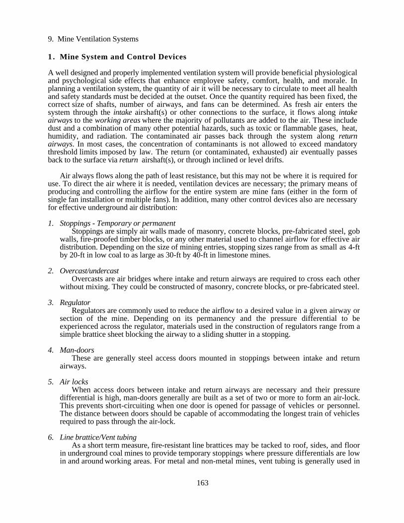
1 . Mine System and Control Devices
A well designed and properly implemented ventilation system will provide beneficial physiologicaland psychological side effects that enhance employee safety, comfort, health, and morale. Inplanning a ventilation system, the quantity of air it will be necessary to circulate to meet all healthand safety standards must be decided at the outset. Once the quantity required has been fixed, thecorrect size of shafts, number of airways, and fans can be determined. As fresh air enters thesystem through the intake airshaft(s) or other connections to the surface, it flows along intakeairways to the working areas where the majority of pollutants are added to the air. These includedust and a combination of many other potential hazards, such as toxic or flammable gases, heat,humidity, and radiation. The contaminated air passes back through the system along returnairways. In most cases, the concentration of contaminants is not allowed to exceed mandatorythreshold limits imposed by law. The return (or contaminated, exhausted) air eventually passesback to the surface via return airshaft(s), or through inclined or level drifts.
Air always flows along the path of least resistance, but this may not be where it is required foruse. To direct the air where it is needed, ventilation devices are necessary; the primary means ofproducing and controlling the airflow for the entire system are mine fans (either in the form ofsingle fan installation or multiple fans). In addition, many other control devices also are necessaryfor effective underground air distribution:
1. Stoppings - Temporary or permanentStoppings are simply air walls made of masonry, concrete blocks, pre-fabricated steel, gob
walls, fire-proofed timber blocks, or any other material used to channel airflow for effective airdistribution. Depending on the size of mining entries, stopping sizes range from as small as 4-ftby 20-ft in low coal to as large as 30-ft by 40-ft in limestone mines.
2. Overcast/undercastOvercasts are air bridges where intake and return airways are required to cross each other
without mixing. They could be constructed of masonry, concrete blocks, or pre-fabricated steel.
3. RegulatorRegulators are commonly used to reduce the airflow to a desired value in a given airway or
section of the mine. Depending on its permanency and the pressure differential to beexperienced across the regulator, materials used in the construction of regulators range from asimple brattice sheet blocking the airway to a sliding shutter in a stopping.
4. Man-doorsThese are generally steel access doors mounted in stoppings between intake and return
airways.
5. Air locksWhen access doors between intake and return airways are necessary and their pressure
differential is high, man-doors generally are built as a set of two or more to form an air-lock.This prevents short-circuiting when one door is opened for passage of vehicles or personnel.The distance between doors should be capable of accommodating the longest train of vehiclesrequired to pass through the air-lock.
6. Line brattice/Vent tubingAs a short term measure, fire-resistant line brattices may be tacked to roof, sides, and floor
in underground coal mines to provide temporary stoppings where pressure differentials are lowin and around working areas. For metal and non-metal mines, vent tubing is generally used in
163

9. Mine Ventilation Systems
and around working areas to channel fresh air to operating faces. Vent tubing is also commonlyused in combination with auxiliary fans.
7. Booster/auxiliary fansWhen the airflow in a section of the mine must be adjusted to a magnitude beyond that
obtainable from the open system, a booster fan may be used to enhance the airflow through apart of the mine. When they are used, they should be designed into the system in order to helpcontrol the leakage, without causing undesirable recirculation in either normal or emergencysituations. In the U.S., booster fans are prohibited in underground coal mines.
8. Machine-mounted watersprays and scrubbersThese are devices used to enhance the flow of fresh air in face areas. Scrubbers are "vacuum
cleaners" used for dust suppression, while watersprays, when strategically located onmachines, have been used successfully to act as a "booster fan" to re-direct airflow in certaindirections in face areas.
2 . Major Ventilation Systems
The objective of any ventilation system is twofold. First, the primary ventilation must course airthrough the main airways to the immediate working area outby the working faces, thus makingfresh air available for face ventilation, and then return the contaminated air through return (exhaust)airways to the surface. Second, the face ventilation system must be designed to effectively utilizethe available air in the immediate working area to sweep the working face, to capture and removedust, and to dilute and carry away gas, if any, emitted during mining activities. Without a properlydesigned ventilation system, an efficient production cycle would not be possible. The systemshould provide the required air volumes and quality at reasonable pressure losses, perform withminimum interference and cost to production, and do so in the most cost-effective way possible.Furthermore, the primary ventilation system may be well designed, but if the available air broughtto the working area is not properly utilized for ventilating the faces where most workers arelocated, the total system has failed (Bossard, et al., 1982).
Depending on the type of mine and disposition of local geology, ventilation layouts can bedivided into two broad classifications; either a U-tube system or a through-flow arrangement(Figure 9-2, McPherson, 1993). Figure 9-2a shows a basic U-tube configuration where air flowstowards and through the working area, then returns along adjacent airways, often separated fromintakes by long pillars and/or stoppings. Access doors in the stoppings facilitate traffic betweenintake and return airways. The variation of this arrangement would be room-and-pillar andlongwall type mining methods. The other arrangement is shown in Figure 9-2b, where intakes andreturns are usually separated geographically from adjacent airways, which are either all intakes orall returns. Although fewer stoppings and airways are needed because of the geographicalseparation, which often results in less air leakage, air current regulations and boosters may berequired for airflow control in work areas (McPherson, 1993). Parallel flows between intake andreturn airshafts across the multilevel metal mines and the bleeder system in a longwall panel wouldbe typical examples of this type layout.
Actual layouts underground could be variations of any one system or a combination of the twoarrangements.
164

9. Mine Ventilation Systems
Intakes
Workings
Intakes
Returns
Workings
(a) (b)
Figure 9-2. Basic ventilation systems (a) U-tube and (b) through-flow (McPherson, 1993).
For Stratified Deposits
The vast majority of underground mines extracting tabular forms of orebodies (coal, potash, salt,limestone, etc.) normally use one of two methods, longwall or room-and-pillar mining. While ac-tual layouts can vary significantly from mine to mine and region to region according to localgeological conditions, the basic design for these two methods remains the same. The followingsections describe the airflow distribution system usually employed.
a) Longwall systems
Two factors that have significantly influenced the design of the longwall ventilation systems are thecontrol of methane or other gases that accumulate in the gob area (Haake, et al., 1985; Highton,1980; McPherson, 1993; den Drijver, et al., 1997; Diamond, 1997; Dziurzynski and Nawrat,1997) and the increasing high rate of rock breakage on heavily mechanized longwalls that has ex-acerbated the production of dust, gas, heat, and humidity (Uchino and Hirago, 1984; Battino andMitchell, 1985; Organiscak and Jankowski, 1996; Colinet, et al., 1997; Stokes and Tuck, 1997).
Figure 9-3 depicts some of the commonly used ventilation layouts used on longwall sections.In the U.S., a minimum of two entries is required, while single entry longwalls are primarily em-ployed in European coal mines (Fuller, 1989; McPherson, 1993).
System layouts become more complex when mining under inclined, thick, and gassy coalseams with frequent faults. Narrower and shorter panels are necessary to cope with these difficultconditions. There also have been other type of layouts to accommodate specific geological condi-tions (Fuller, 1989 and Tien, 1995).
165

9. Mine Ventilation Systems
++
+
+
(a) (b) (c) (d)
Figure 9-3. Classifications of longwall ventilation systems (a) single-entry advancing; (b)single-entry retreating; (c) single-entry retreating with back bleeder; (d) double-entry retreating with back bleeder (after McPherson, 1993).
(e) (f) (g)
Figure 9-3a. Classifications of longwall ventilation systems (e) Y-system; (f) double-Zsystem; (g) W-system. (after McPherson, 1993).
b) Room and pillar systems
Figure 9-4 shows the two methods of ventilating a room and pillar development panel in a coalmine where multiple entries are driven. Figure 9-4a is the directional, or W-system, in which in-take air courses are airways in the central portion of the panel, with return airways on both sides,often referred to as the fish-tail method. The method in Figure 9-4b is the unidirectional system inwhich intake and return are located on both sides of neutral airway (belt and track).
In both cases, the conveyor belt and/or track are located in the middle, with a brattice curtain atthe end to regulate the airflow. In U.S. coal mines, unless a special petition is approved by MSHAin advance, air in these entries is not supposed to be used to ventilate working areas under normalcircumstance, so they are directed directly to the return airway through a regulator. Advantages ofthis system include: the airflow splits at the end of the panel, with each airstream ventilating the op-erational rooms sequentially over one half the panel only, resulting in less leakage due to less pres-sure differential across the stopping; and any gas emission will be flowing automatically to returnairways. An obvious disadvantage is that the number of stoppings required is double that of theuni-directional system. The air leakage also is twice as much due to the extra stoppings(McPherson, 1993).
166

9. Mine Ventilation Systems
Inta
ke A
ir
Ret
urn
Air
Inta
ke A
ir
Ret
urn
Air
Ret
urn
Air
Inta
ke A
ir
(a) (b)
Figure 9-4. Room and pillar development with line brattices to regulate airflow in conveyorbelt entry: (a) bi-directional system; (b) uni-directional system.
A uni-directional system should offer a higher volumetric efficiency at the face because of thereduced number of stoppings. A disadvantage is that the higher volume also has a higher ventila-tion pressure, which in turn offers higher leakage.
c) Mine with large-size entries
Typically, mines with large-size entries (e.g., limestone, salt, and oil shale) require large volumesof ventilating air (between 350,000 to 500,000 cfm, depending on specific conditions) to ade-quately ventilate underground workings. In trying to meet this requirement, two major problemsare usually encountered: (1) excessive air leakage through stoppings and (2) local air recirculation,both of which are caused by improperly constructed (and maintained) stoppings, or the lack ofstoppings in many cases, and both can adversely affect the underground working environment.Oftentimes, mine management are reluctant to construct an adequate number of stoppings, eitherbecause of technical problems or the associated expenses.
Air is used to dilute diesel exhaust and to maintain a minimum air velocity in large-dimensionairways in order to avoid air stratification, and every reasonable measure has to be taken to ensurethat fresh air is effectively delivered to working places where air is needed. The cost of not main-taining adequate ventilation results in a poor working environment that not only is in violation offederal and state regulations, but can adversely affect worker performance and morale. To deliverfresh air to working places over large distances, effective air distribution system is essential. Theycan either be: (1) conventional large-scale stoppings using pipes with metal sheeting, brattice andwire, a muckpile, etc. or (2) adopting a modular type pillar layout.
Constructing air-tight stoppings in large openings is not only time-consuming and expensive, itoften is difficult, if not impossible, to be 100% effective (Adam, et al., 1987; Thimons, et al.,1987). The precise cost of constructing conventional metal-frame stoppings in a 35-ft wide by 20-ft high entry is difficult to obtain because of the many variables involved, e.g., ranging from$20,000 to $24,000 per stopping in a limestone operation in Iowa (in 1996 dollars).
167

9. Mine Ventilation Systems
Oftentimes, brattice curtains are the only practical materials for use underground; the cost ofwhich ranges from $1,500 to $3,000 per stopping (1997 dollars). This includes the cost of laborand materials. However, stoppings such as these are subjected to much higher leakage between thestrips of brattice and around the peripherals. Leakage varies depending on many factors, such asworkmanship, maintenance, mining practices (stoppings too close to working areas will suffer fre-quent blasting damage), and, to a lesser extent, geological conditions (roof sagging and bottomheaving can damage stoppings). A salt mine in Ohio with 20-ft x 40-ft entry sizes showed a leak-age rate of 5,100 to 5,500 cfm per stopping.
Some mines have hung a continuous brattice line along the pillars, which stops most the leak-age around the peripherals (Figure 9-5).
Pillar line
Continuous Brattice Line
Airflow
Figure 9-5. A continuous brattice line will reduce leakage around peripherals.
Although the exact impact on power cost due to leakage is difficult to quantify, it is known tobe significant. Since any leakage through a stopping has to be compensated for by "pumping"more air underground to meet safety requirements, it will dramatically increase energy require-ments at the fan because fan power and air quantity have a cubic relationship. For example, a 26%increase in air flow would double the air power cost. Costs of other types of stoppings also can beestimated roughly in today's dollars using published information (Adam, et al., 1987; Thimons, etal., 1988).
A modular configuration provides an alternative. In this layout, long barrier pillars areintentionally left at four sides of a pre-planned mining block so air can be effectively coursed overlonger distances. The following diagram (Figure 9-6) shows a hypothetical mine working with amodular configuration.
There will be small losses in percentage extraction. However, this loss can be reduced to aminimum by leaving only the last round of mining in a cross-cut (Figure 9-6). The reduction in airleakage, plus the savings created by replacing brattice and providing effective ventilation, will off-set the cost associated with a lower extraction ratio. The following diagrams show the extractionratio calculations. Figures 9-7a and 9-7b show 40-ft by 40-ft pillars mined on 70-ft centers.Calculations show that the difference in production is approximately 6%. But a more realistic fig-ure would be around half that, or 3%, because only a fraction of the partial pillars are left on foursides within this block. Figures 9-7c and 9-7d show a similar 70-ft center pillar pattern, however,35-ft by 35-ft pillars are left. The difference caused by leaving a partial pillar is around 3.5%.
168

9. Mine Ventilation Systems
Intake
Fresh Air
Return Air
Mining Boundary
Mining Module
Return
Figure 9-6. A hypothetical underground limestone mine where a module system is used inlieu of stoppings to channel air to working areas.
40'
40'30'
10'
70'
30'
60'
70'
40'
40'30'
70'
30'
70'
Full extraction: 1 – 40 x 4070 x 70
= 67.3% Leaving partial pillar: 1 – 35 x 35 + 35 x 1070 x 70
= 67.9%
(a) (b)
Figure 9-7. Extraction ratio calculations.
Full extraction: 1 – 35 x 3570 x 70
= 75.0%
Leaving partial pillar: 1 – 35 x 35 + 35 x 1070 x 70
= 67.9%
169
9. Mine Ventilation Systems
35' 35'
10'
70'
70'
60'
35'
35'
35' 35'
70'
70'
35'
35'
(c) (d)
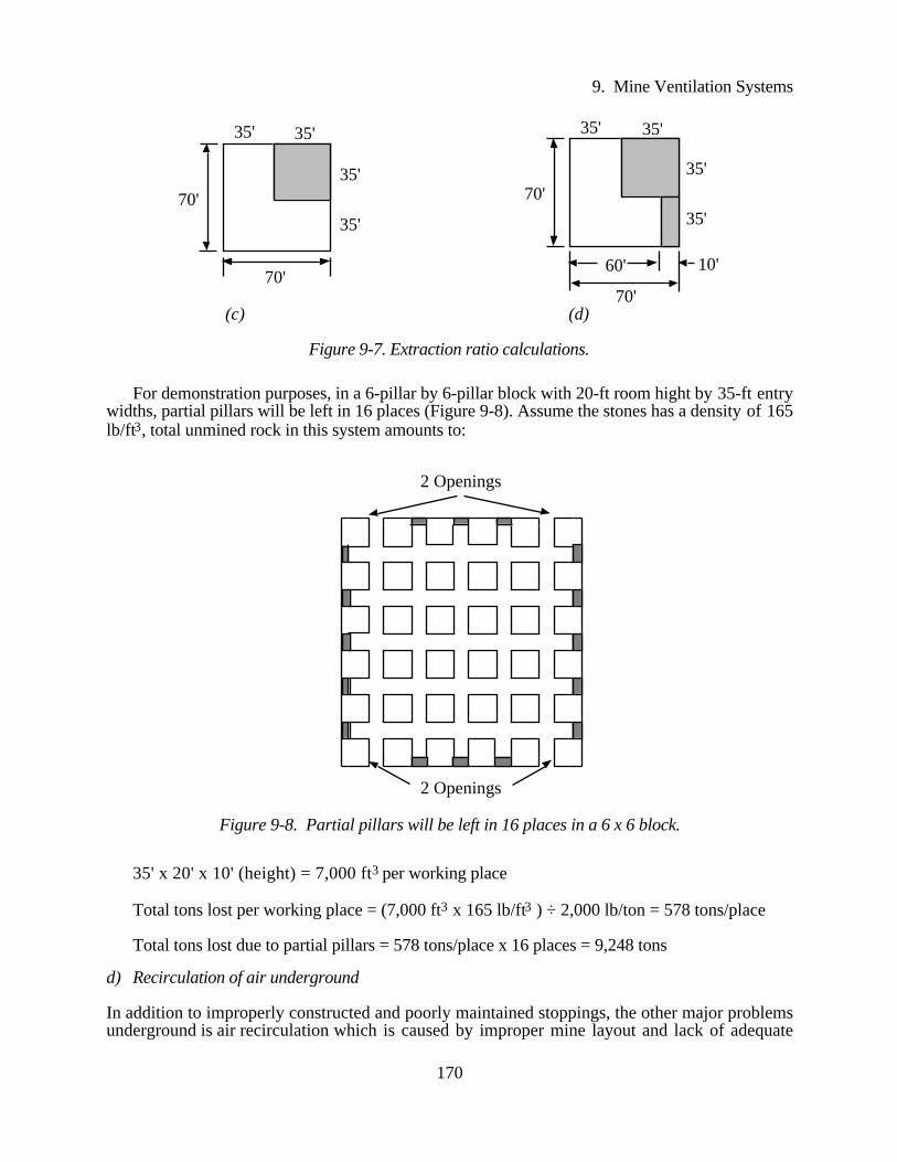
Figure 9-7. Extraction ratio calculations.
For demonstration purposes, in a 6-pillar by 6-pillar block with 20-ft room hight by 35-ft entrywidths, partial pillars will be left in 16 places (Figure 9-8). Assume the stones has a density of 165lb/ft3, total unmined rock in this system amounts to:
2 Openings
2 Openings
Figure 9-8. Partial pillars will be left in 16 places in a 6 x 6 block.
35' x 20' x 10' (height) = 7,000 ft3 per working place
Total tons lost per working place = (7,000 ft3 x 165 lb/ft3 ) ÷ 2,000 lb/ton = 578 tons/place
Total tons lost due to partial pillars = 578 tons/place x 16 places = 9,248 tons
d) Recirculation of air underground
In addition to improperly constructed and poorly maintained stoppings, the other major problemsunderground is air recirculation which is caused by improper mine layout and lack of adequate
170

9. Mine Ventilation Systems
stoppings. One of the commonly encountered planning errors in underground limestone operationsis that main intake and return airways are located adjacent to each other, causing the exhaust air tobe recirculated back into intake airway(s). This situation is exacerbated when a box cut, often usedin limestone and coal mines where ore crops out, is used to enter the mine. The air can not bedischarged away from the intake area.
At the early stage of the mine development, main intake and return airways are usually locatednear each other, and it will be at least several years before an airshaft can be drilled some distancefrom the portal and an entire ventilation circuit can be completed. It is recommended that intake andreturn in the portal areas be physically separated in the start up of the mine to avoid air recirculation(Figure 9-9).
Fresh airReturn air
Exhaustfan
Figure 9-9. Fan duct is used to deflect exhaust air and to recover lost velocity pressure.
If this is not possible, and both intake and return have to be located next to each other at thebottom of the boxcut, Figure 9-10 shows an alternative method of separating intake air and returnair by the use of a vertical fan duct at the discharge end of the exhaust fan.
Mine fan
Surface
Bulkhead
> 80 ft
Fan duct to deflectair to recover fanvelocity pressure
Figure 9-10. Fan duct is used to deflect exhaust air and to recover lost velocity pressure.
Figure 9-10 shows a suggested layout where exhaust air is deflected upward using a vertical
171

9. Mine Ventilation Systems
duct (evasè) at least 80 feet in length. The evasè also serves another useful purpose: it can recoverfan velocity pressure (ranging from 0.2 in. to 1 in. W.G. depending on fan discharge velocity)which otherwise would be lost. To avoid additional shock losses, the connecting bend should beround and smooth.
Local recirculation occurs primarily because of (1) inadequate number of or leaky stoppings or(2) non-bulkheaded auxiliary fans. As a result, air will move in and out of return areas on the otherside of stoppings, or circles around the auxiliary fan without going to working faces. Constructingadequate number of stoppings and properly locating auxiliary fans are primary means for reducinglocal recirculation. See Chapter 20: Controlled Recirculation for details.
Some of the other characteristics for mines with large openings are their low air velocity inairways which can result in air stratification, or fogging, in airways caused by influx of groundwater and seasonal moisture content fluctuation. Excessive and fluctuating moisture content in aircan also contribute to the deterioration of roof layers, causing safety problems. Also, for limestoneoperations, the combination of grade variation and fluctuating market demand requires certainflexibility in mine development, which also will impact ventilation planning.
Air Tempering for Roof Stability
In a mine with large openings, in the summer and sometimes in late spring and early fall, as warm,humid air enters the mine entries, air velocity is greatly reduced due to these large openings. Theair starts to interact with the surrounding rock and quickly reaches mine temperature. As air tem-perature is reduced, its relative humidity will rise until the air is unable to carry the high moisturelevels. Moisture at that point begins to condense on, or be absorbed by, surrounding rocks. Theintake air continues to cool and dry along the length of the entries until an equilibrium is reachedbetween mine temperature and specific humidity levels.
Laboratory studies have shown that very short term (daily) fluctuations in specific humidityhave little or no effect on shale moisture gains or losses. Shales require a 7- to 10-day exposure tochanges in specific humidity, whether higher or lower, before equilibrium between moisture con-tent in the rocks and atmospheric conditions is reached (Haynes, 1975; Anon., 1976; Stateham andRadcliffe, 1978; Cummings, et al., 1983; and Sames, 1985). As the intake air travels along theentries, contact is made with rock and other materials in disequilibrium. Gradual moistureexchange takes place from that point at increasing residence time until equilibrium is againachieved. Figures 9-11 and 9-12 show the seasonal effects (humidity and temperature) for anearlier study in a coal mine where the roof is predominately shale.
Moisture exchanges between incoming air and surrounding rocks are site specific. Althoughthe exact moisture absorbing characteristics of the rock are not known, studies on shale in othermines can be used as a guideline to reasonably estimate their interactions (Cummings, et al.,1983). Previous USBM research indicates that the maximum efficient air residence time fortempering summer air is 30 minutes; additional residence time will provide total tempering. In theabove mentioned study, 60 grains per pound of dry air is assumed as a good approximate summermoisture equilibrium value and its results showed a 70% reduction in excess moisture in 15minutes residence time. It was estimated that, if the residence reached 30 minutes, moisturereduction could be expected to reach 90 to 95% tempering. Based on this, a minimum of 15minutes residence time can be used as a good design parameter that will provide sufficienttempering effect (Lucas, 1975; Haynes, 1975; Anon., 1976; Stateham and Radcliffe, 1978).Having adequate air velocity is the most effective means for reducing moisture condensation.
172

9. Mine Ventilation Systems
June
June
10
20
30
40
50
60
70
80
90
100
160 2 4 146 128 10Air Residence, min.
February
Figure 9-11. Changes in mine air specific humidity as a function of air residence time(After Sames, 1985).
160 2 4 146 128 10Air Residence, min.
20
30
40
50
60
70
80
Figure 9-12. Changes in mine air temperature as a function of air residence time (AfterSames, 1985).
173

9. Mine Ventilation Systems
Orebody Deposits
Metalliferous orebodies often occur in deposits of irregular geometry, varying from tortuous veinsto massive irregularly shaped deposits of finely disseminated metal and highly variable concentra-tions. This causes mining layout necessarily less ordered than those for stratified deposits. In addi-tion, the grade variation in metal mines and ever-changing metal prices necessitate that more stopesor working places be developed than would appear to be necessary, while with perhaps only afraction of them operating on any one shift. Thus, the ventilation shift must be sufficiently flexibleto allow airflow to be directed wherever it is needed on a almost day-by-day basis (McPherson,1993).
Ventilation networks for metal mines tend to be more complex than for stratified deposits andusually are also three dimensional. Figure 9-13 illustrates the ventilation plan of many metal mines,although the actual geometry will vary widely.
R
R
R
R
R
R
Upcast shaftor ramp
Downcast shaftor ramp
Main level
Sub level
Figure 9-13. Section showing the ventilation system for a metal mine.
Airflow distribution systems for individual stopes also are subject to great variability, depend-ing on the geometry and grade variations of the orebody. In most of the cases, where controlledvertical movement of the air is required, stope airflow systems employ ascensional ventilation.Although auxiliary fans and ducts may be necessary at individual drawpoints, every effort shouldbe made to utilize the mine ventilation system to maintain continuous airflow through the main in-frastructure of the stope. Series ventilation between stopes should be maintained so that blastingfumes can be cleared quickly and efficiently (Figure 9-14).
With respect to fan locations and airflow direction, there are primarily three ventilation systems:exhaust (pull) system, where the mine fan is located on top of the return airshaft; blowing (push)system, with the mine fan installed at the intake airshaft; and combined system (push-pull), withfans on both the intake and return airshafts. This refers to main ventilation systems only; local ar-rangements, for example a face ventilation system for a working area, can be different from themain system.
174

9. Mine Ventilation Systems
Main return to upcast shaft
Vent raise
Ventraise
Brokenor or fill
From intake airshaft
Orepassor serviceraise
Figure 9-14. An example of a simple ventilation system for shrinkage or cut-and-fill stopes.
Depending on the particular system, the mine pressure could be either negative (exhaustingsystem, since the fan creates a suction in the system, putting mine pressure below the atmosphericdatum) or positive (blowing system). This is because the mine pressure is measured against atmo-spheric pressure, as shown in Figure 9-15:
Atmospheric Pressure
Exhausting Fan GeneratesNegative Pressure
Blowing Fan GeneratesPositive Pressure
Absolute Zero
Figure 9-15. Schematic showing a positive mine pressure for blowing system and anegative mine pressure for exhausting system.
The best way to describe the relation between pressure loss and air traveling distance is to use apressure gradient, as shown in Figures 4-14 and 4-15. The coal mine in Figure 4-14 shows thatpressure loss is zero at the surface, slowly building up to approximately 0.2 in. W.G. as it pro-ceeds 2,000-ft underground. Pressure drop accumulates to 0.7 in. W.G. after 9,000-ft just beforethe longwall section. Total mine pressure is – 6 in. W.G. at the end of the circuit. The negativesign simply means it is an exhaust ventilation in which pressure is lower than the atmosphericpressure. Similar gradient is also demonstrated in Figure 4-15.
Airflow Direction
Airflow direction is affected by the location of the main fan which, in turn, will significantly impactthe other aspects of operation or transportation. An antitropal system is one in which the airflowand transported rock move in opposite directions, implying that the mineral transportation is carriedout in intake airways. This tends to put restrictions on the air velocities in intake airways so thatdust and other gases will not be too excessive. Conversely, a homotropal system is one where the
175

9. Mine Ventilation Systems
airflow and the mined rock move in the same direction, or the haulage is carried out in return air-ways. This system will ensure that dust, heat, and other pollutants from broken rock will be venteddirectly to the outside. In addition, this system also has the advantage in case of fire occurring inthe haulageway.
Another factor in airflow direction is the inclination of the airway. An ascensional ventilation iswhen the airflow moves upwards through inclined workings. This takes advantage of the naturalventilation effects caused by the added heat to the air. Descensional ventilation may be employedon a more compact system, with both air and conveyed materials moving downhill.
It is the pressure difference that causes air to flow underground, regardless of how this pres-sure difference is generated. There are different merits and drawbacks in each system. A particularsystem must be selected to accommodate the specific mining situation, and not the ventilation de-signer's pet theories. The following is a list of pros and cons for both arrangements (Tien, 1978):
1) Exhausting System
Advantages:a) When main fan stops, underground pressure builds up to atmospheric. The increase in
pressure slows gas emissions from the gob and prolongs the time required for the gas toreach active workings.
b) The haulage roads, where most travel is done, are kept free from dust, gas, and smoke.This permits the men to perform their work in fresh air.
c) In the event of a fire or explosion, exhausting ventilation enables the rescue work to pro-ceed more rapidly, because the fresh air is on the haulage road, which provides an easyroute for carrying material and equipment to make mine repairs.
d) Both intake airways and track entries serve as escapeways, if stopping lines are well main-tained.
e) Greater power savings are possible if mine openings are small. This is due to the poten-tially greater recovery of velocity pressure through the use of discharge evasè (gradual ex-pansion ducts) on exhaust fans.
Disadvantagesa) It reduces temperatures in the belt slope, slope bottom, and main haulage line. During win-
ter, the belt sprinkler system, damp coal on the belt rollers, and water lines along thehaulageway can freeze. The temperature also is uncomfortable for the people working inthese areas.
b) It is more difficult to detect a fire in belt and track entries since the air is carried directly tothe return airways.
c) Dust produced at the portals and along the haulage road contaminates the intake air stream.Similarly, fire in the belt and track entries can be carried to the working areas.
d) Contaminated air goes through the fan, corrosive particles settle on the fan blades andcorrode them, reduces effective air passage area, and can throw the fan out of balance.
2) Blowing System
Advantagesa) It applies a continuously decreasing overpressure from the air intake portal to the discharge
opening. This characteristic produces airflow from intake airways to the return and pre-vents contaminated flow into working areas from idle areas and return airways. In fact, theblowing system may be the only practical method of ventilation in shallow mines havingfractured ground, as well as areas of contiguous mining where there may be ground cracks
176

9. Mine Ventilation Systems
into abandoned mines.b) The haulage roads and hoisting shaft stay free from ice, making it more comfortable for the
men in winter.c) A fire in any part of the mine is soon evident, due to leakage, to anybody working in the air
current coming away from the face area.d) Only outside air, non-corrosive and with normal moisture content, goes through the fan.e) Fan unit is cheaper because of a shorter fan duct (diffuser).
Disadvantagesa) Products of combustion from a mine fire or explosion are carried into the neutral escape-
way. Thus, fire-fighting and rescue work are more difficult because access is often blockedby smoke. Ventilation reversal, in these cases, may endanger the men.
b) Dust, smoke, and other impurities are carried away from the face area and along thehaulage road. Methane tends to accumulate in pockets in the roof, sometimes causing slightexplosions.
c) Since neutral air flows away from working sections to the slope bottom, any accumulatedair contaminants converge on workmen in the slope bottom area.
d) Shock losses are greater. It requires a distance of 30 times the duct diameter away from thepressure jet for the air velocity to lose 90% of its original velocity. For an exhausting sys-tem, only one duct diameter distance is required to lose 90% of its velocity. As result, pres-sure loss caused by shock, which is in addition to frictional loss, is considerably more in ablowing system.
e) Dirt and dust from outside will settle on the fan blades.
3) Push-pull (combination) System
In the push-pull system, it is easier to get air to difficult places. The disadvantage of this system isthat it is harder to balance the ventilation system, resulting in neutral spots in the mine. Accordingto recent survey, the majority of the underground coal mines in the U.S. use exhausting ventilationas their main ventilation system.
3 . Ventilation Planning and Designing
The ultimate goal for ventilation planning is to design a system that will be capable of adequatelyventilating all working faces, airways, and areas underground at minimum costs. A good mineventilation system always begins with the initial development of the mining plan, which should al-ways have alternatives. A well-thought out ventilation system can minimize long-term problems,builds in flexibility for expansion without exorbitant cost, reduces up-front capital expenditures,and phases in capital outlay over the life of the project (Bossard, et al., 1982).
Air volume requirements can be substantial in some operations. The presence of diesel,gaseous products, strata gases, heat and humidity, and large openings all require a significantincrease in the minimum air velocity required, and hence a higher air volume requirement. Sinceenergy requirement is proportional to the cube of air volume circulated, optimization between airvolume and resistance must be considered. Other factors also must be factored in, such asenvironmental requirements and available resources. Figure 9-16 shows a basic model for planninga new underground mine (Viljoen, 1990).
177

9. Mine Ventilation Systems
Sec. vent. req'tsAirway velocitiesShaft velocitiesLeakage rateVent. method
In sectionsLeakageTotal Req't
PrimarySecondaryTertiary
Number of shaftsD/C capacity/sizeU/C capacity/size
Environmental Requirements
Shaft Sizes
Air VolumeRequirement
AirwayRequirements
DesignParameters
Manpower req'tAuxiliary fansRescue equip'tGas detectorsMonitoring equip't
Surface fansRescue equip'tEmergency roomsRock dust silos
Resources Required
Underground Resources
SurfaceResources
Vent. of all workingsRescue strategyMonitoring StrategyNoise control Strategy
1, 2, 5 year and lifeof mine plans
Seam heightPillar centersProduction
Mining methodNumber of sectionsGeo. information
Methane emission rateStatutory req'tsOther relevant info.
ObtainInformation
MiningParameters
DefineStrategy
Mine Plans
MiningLayouts
General
Figure 9-16. Factors considered in planning a new mine (Viljoen, 1990).
Although many factors enter into an ultimate ventilation planning scheme, minimizing frictionand shock losses are the two most important among all the items considered.
1. To minimize friction losses
From the equation,
R = KOL
5.2A3N2
anything that can lower K , O, and L and increase A and N will reduce R, and ultimately lowercosts in terms of having lower overall ventilation pressure, realizing that there will be practicallimitations.
2. To minimize shock losses
Since up to 30% of total losses underground comes from shock losses, it is essential that shocklosses be minimized to lower costs. From the equation,
Hx = XHv
The obvious thing to do is to lower shock loss factor, X , for given air velocity. This can be
178

9. Mine Ventilation Systems
achieved by rounding off corners, avoiding sudden air velocity and airflow direction changes,etc.
4 . Ventilation Planning and Design Parameters at Homestake – A Case Study
The goal of a ventilation system is to provide a work environment that contains minimal safety andhealth risks and is conducive to hard work. Since ventilation is a cost function, this goal should bemet as inexpensively as possible.
Homestake is the largest underground gold mine in the U.S., currently operating at the 8,000-foot level. The mine is ventilated by 1,069,000 cfm (504 m3/sec) of air measured at mid-exhaust-circuit density. Its air conditioning system includes a 2,300 ton (8.1 MWR) controlled recirculationplant, a 580 ton (2.0 MWR) chilled water plant, a 290 ton (1.0 MWR) drite exploration plant, 28spot-coolers totaling 960 tons (3.4 MWR), and 35 spray coolers totaling 420 tons (1.5 MWR).The mine employs 117 diesel units with a total nameplate rating of 10,672 hp (7,961 kW), plusother mining equipment (Marks and Shaffner, 1993).
Faced with these challenges, the mine management formulated a ventilation planning methodcalled Requirements and Resources Analysis (Marks and Justus, 1993). A requirement is definedas the air quantity or the amount of refrigeration necessary to meet the goal stated above. Aresource is a tangible thing: a fan, cooler, or an airway. A properly designed system has theresources to meet the requirements. If not, work areas will be excessively warm or cold, or willsuffer from high contaminant concentrations. Requirements and Resources Analysis has four basiccomponents: 1) Establishing and justifying design parameters, 2) ascertaining present ventilationsystem status, 3) projecting ventilation requirements, and 4) analyzing ventilation resourcesalternatives.
Design parameters specify what is too hot or too cold, what concentrations of contaminants aretoo high, and what specific air quantities and velocities are used for specific operations. For heat,the economic temperature range for work is 80° to 85°F wet-bulb, designated as the design rejecttemperature. The 85° to 91°F wet-bulb increment is considered the safety-factor range where onlytemporary work is permitted. Above 91°F wet-bulb, ingress is for short duration only.
For dust, toxic and dangerous gases, the guidelines set forth by Mine Safety and HealthAdministration (MSHA) and the American Conference of Governmental Industrial Hygienists(ACGIH) are followed. For diesel equipment, a minimum 110 cfm per rated horsepower (0.07m3/sec per kW) is specified for ramp systems and general work areas. Dead and auxiliary fans canget by with less air if diesel vehicles are only in the heading part-time. Scrams under 100 ft inlength usually are well enough ventilated by convection currents and the reciprocating action of theloader.
References
Adam, et al. (1987) "Leakage Testing of Large Ventilation Control Structures for Room and PillarOil Shale Mining," Proc. 3rd U.S. Mine Vent. Sympo., Mutmansky, J.M., ed., SME,Littleton, CO, pp. 365-370.
Anon. (1976) "Humidity Effects on Coal Mine Roof Stability," USBM Contract #H0232057,OFR 5-78, 164 pp.
Bossard, F.C., et al. (1982) "Chap. 22: Primary Mine Ventilation Systems," A Manual of MineVentilation Design Practices, First Ed., Floyd C. Bossard & Asso., Inc., Butte, MT, 2 pp.
179

9. Mine Ventilation Systems
Cummings, R.A., Singh, M.M., and Moebs, N.N. (1983) "Effect of Atmospheric Moisture onthe Deterioration of Coal Roof Shales," Min. Engrg., Mar., pp. 243-245.
Haynes, C.D. (1975) "Effects of Temperature and Humidity Variations on the Stability of CoalMine Roof Rocks – Final Report," USBM Contract # H0122111, OFR 8-77, 385 pp.
Highton. W. (1980) "The Case Against Bleeder Entries and the Reasons for a Safer and MoreEfficient Alternative," Proc. 2nd Int'l Mine Vent. Cong., P. Mousset-Jones, ed., SME-AIME,NY, pp. 437-447.
Lucas, W.S. (1975) "Tempering Mine Air to Prevent Roof Falls," Proc. Illinois Min. Inst. AnnualMeeting, Oct., pp. 47-55.
McPherson, M.J. (1993) "Chap. 9: Ventilation Planning," Subsurface Ventilation and Environ-mental Engineering, Chapman & Hall, New York, pp. 282-321.
Sames, G.P. (1985) "Coal Mine Air Tempering: Effectiveness, Design, and Roof Support,"USBM Rpt Investigation No. 8955, 20 pp.
Stateham, R.M. and Radcliffe, D.E. (1978) "Humidity: A Clyclic Effect in Coal Mine RoofStability," USBM Rpt Investigation No. 8291, 19 pp.
Thimons, E.D., et al. (1988) "Leakage and Performance Characteristics of Large Stoppings forRoom-and-Pillar Mining," USBM Rpt Investigation No. 9148, 17 pp.
Tien, J.C. (1978) "Pros & Cons of Underground Ventilation System," Coal Min. & Proc., Jun.,pp. 110-113.
Tien, J.C. (1997) "Chap. 17: Longwall Mining," Short Course Text, University of Missouri-RollaPress, Rolla, Missouri, Apr., pp. 341-378.
Uchino. K. and Hiraga, T. (1984) "Control of Thermal Environmental Conditions in a RetreatingLongwall Coal Face by E- and W Ventilation Systems," Proc. 3rd Int'l Mine Vent. Cong.,Howes. M. J. and Jones. M. J., eds., Inst. Min. and Met.. London, pp. 339-342.
Viljoen, P.L.J. (1990) "Planning of a New Colliery (Flow Diagram)," Journ. Mine Vent. Soc. ofSouth Africa, Apr., p. 80.
Longwall Ventilation
Banerjee, S.P. et al (1984) “Methane Emission and Control in Caved Longwall Faces in MoonidihColliery, India,” Proc. 3rd Int'l Mine Vent. Cong, Howes, M.J. and Jones, M.M., ed., Inst.of Min. Engrs., London, England, Jun., pp. 171-176.
Battino. S. and Mitchell. P.B. (1985) "Ventilation Experiences with Longwall Mining atMacquarie Colliery," Proc. of the 2nd U. S. Mine Vent. Sympo., Mousset-Jones, P., ed.,A.A. Balkema, Rotterdam, pp. 409-418.
Cecala, A, Konda, B.W. and Klinowski, G. W. (1989) “A Comparison of Methane Flow Patternson Advancing and Retreating Longwalls,” Proc. 4th U.S. Mine Vent. Sympo., McPherson,M.J., ed., SME, Littleton, CO, pp. 484–490.
Cecala, A. B. et al (1985) “Determining Face Methane Liberation Patterns During LongwallMining,” Proc. 2nd U. S. Mine Vent. Sympo., Mousset-Jones, P., ed., A.A. Balkema,Rotterdam, pp. 361-367.
Colinet, J.F., Spencer, E.R., and Jankowski, R.A. (1997) "Status of Dust Control Technology onU.S. Longwalls," Proc. 6th Int'l Mine Vent. Cong., Ramani, R.V., ed., SME, Littleton, CO,pp. 345-351.
Compoli, A.A., McCall, F.E., Finfinger, G.L., and Zuber, M.D. (1995) “Potential for ImprovedLongwall Dust Control by Surface Borehole Water Infusion,” SME Annual Meeting, Denver,CO, Mar. 4-9, Preprint # 95-139, 8 pp.
den Drijver, et al. (1997) "Calculation of the Amount of Methane Degassing from Longwall Basedon a Mathematical-Physical Model," Proc. 6th Int'l Mine Vent. Cong., Ramani, R.V., ed.,SME-AIME, NY, pp. 237-241.
Diamond, W.P., et al. (1997) "Analysis and Prediction of Longwall Methane Emissions: A CaseStudy in the Pocahontas No. 3 Coalbead, VA," Proc. 6th Int'l Mine Vent. Cong., Ramani,
180

9. Mine Ventilation Systems
R.V., ed., SME, NY, pp. 223-229.Divers, E. F. et al (1987) “Ventilation Drum Controls Longwall Dust and Methane,” Proc. 3rd
U.S. Mine Vent Sympo., Mutmansky, J.M., ed., SME, Littleton, CO, pp. 85-89.Divers, E.F. (1991) “Coping with Longwall Dust,” Coal, Jun., pp. 55-57.Dziurzynski, W. and Nawrat, S. (1997) "Optimal Choice of the Parameters for Ventilation and
Methane Drainage in a Longwall Face with Caving," Proc. 6th Int'l Mine Vent Cong., Ramani,R.V., ed., SME, NY, pp. 359-364.
Fuller, J.L. (1989) “An Overview of Longwall Ventilation System Design,” SME Annual Meeting,Las Vegas, NV, Preprint # 89-53, 13 pp.
Garcia, F. and Cervik, J. (1985) “Methane Control on Longwalls With Cross-Measure Boreholes(Lower Kittanning Coalbed),” USBM Rpt Investigation No. 8985, 17 pp.
Goodman, T. W. and Cervik, J. (1986) “Comparisons Between Cross-Measure Boreholes andSurface Gob Holes,” USBM Rpt Investigation No. 9013, 14 pp.
Haake. J., Koppe. U., and Phillip. W. (1985) "Gas Emission and Ventilation in a Working withY-type Ventilation on the Return Side," (English translation), Gluckauf. Vol. 121, pp. 1144-1150.
Haneyn R.A., et al. (1993) “Influence of Airflow and Production on Longwall Dust Control,”Proc. 6th U.S. Mine Vent. Sympo., Bhaskar, R., ed., SME, Littleton, CO, pp. 43-49.
Hanson, B.B. and Poepke, W.W. (1988) “Computer Modeling of Dust and Forces for LongwallMining Systems,” USBM Rpt Investigation No. 9203, 24 pp.
Heising, C. and Becker, H. (1980) “Dust Control in Longwall Workings,” Proc. 2nd U.S. MineVent. Cong., Mousset-Jones, P., ed., SME, NY, pp. 603-611.
Jankowski, R. a. and Babbit, C. A. (1986) “Using Barriers to Reduce Dust Exposure of LongwallFace Workers,” USBM Rpt Investigation No. 9037, 10 pp.
Jankowski, R. A., Kissell, F. N. and Daniel, J. H. (1986) “Longwall Dust Control: An Overviewof Progress in Recent Years,” Min Engrg, Oct., pp. 953-958.
Jankowski, R. A., Organiscak, J. A. and Jayaraman, N. I. (1990) “Dust Sources and Controls onHigh Tonnage Longwall Faces,” SME Annual Meeting, Preprint #90-73, 9 pp.
Lama, R.D. and Liu, Y. (1993) “Use of Diamond Tipped Picks for Dust Control on LongwallFaces,” Proc. 6th U.S. Mine Vent. Sympo., Bhaskar, R., ed., SME, Littleton, CO, pp. 545-549.
Longson, I. and Tuck, M. A. (1985) “The Computer Simulation of Mine Climate on a LongwallCoal Face,” Proc. 2nd U. S. Mine Vent. Sympo., Mousset-Jones, P., ed., A.A. Balkema,Rotterdam, pp. 439-448.
Longson, I., R.D. Lee, and I.S. Lowndes (1985) "The Feasibility of Controlled Air Recirculationaround Operating Longwall Coal Faces," Proc. 2nd U.S. Mine Vent Sympo., Mousset-Jones,P., ed., A.A. Balkema, Rotterdam, pp. 227-237.
Mukherjee, S. K. et al (1985) “Laboratory Investigation on the Effectiveness of an Air SpraySystem for Dust Control on Longwall Faces,” Proc. 2nd U. S. Mine Vent Sympo., Mousset-Jones, P., ed., A.A. Balkema, Rotterdam, pp. 727-732.
Mundell, R. L. et al (1979) "Respirable Dust Control on Longwall Mining Operations in theUnited States," Proc. 2nd Int'l Mine Vent. Cong., Mousset-Jones, P., ed., A.A. Balkema,Rotterdam, pp. 585-593.
Niewiadomski, G.E. and Jankowski, R.A. (1993) "Longwall Dust Trends and Development inLongwall Dust Controls," Proc. 6th U.S. Mine Vent. Sympo., 'Bhaskar, R., ed., SME,Littleton, CO, pp. 551-556.
Ondrey, R.S., Haney, R.A., and Tomb, T.F. (1995) "Dust Control Parameters Necessary toControl Dust on Longwall and Continuous-Mining Operations," SME Annual Meeting,Denver, CO, March 4-9, Preprint # 95-145, 6 pp.
Organiscak, J.A. and Jankowski, R.A. (1996) "U.S. Longwall Practices for ControllingRespirable Dust Sources Outby the Shearing machine," Proc. Respirable Dust Hazard Controlin the Mining Industry, Szczyrk, Poland, Sep. 17-19, pp. 19-25.
181

9. Mine Ventilation Systems
Organiscak, J.A. and Leon, M.H. (1993) "Translucent Face Partition for Longwall Dust Control,"Proc. 6th U.S. Mine Vent. Sympo., Bhaskar, R., ed., SME, Littleton, CO, pp. 557-562.
Organiscak, J.A., et al. (1985) "Factors Affecting Respirable Dust Generation from LongwallRoof Supports," USBM Information Circular No. IC-9019, 19 pp.
Pickering, A. J. and Robinson, R. (1984) "Application of Controlled Air Recirculation toAuxiliary Ventilation Systems and Mine District Ventilation Circuits," Proc. 3rd Int'l MineVent Cong, Howes. M. J. and Jones. M. J., eds., Inst. Min. and Met.. London, pp. 315-322.
Srinivasa, R.B., et al. (1993) "Three Dimensional Numerical Modeling of Air Velocities and DustControl Techniques in a Longwall Face," Proc. 6th U.S. Mine Vent. Sympo., Bhaskar, R.,ed., SME, Littleton, CO, pp. 287-292.
Stevenson, J. W. (1985) "An Operators Experience Using Antitropal and Homotropal LongwallFace Ventilation System," Proc. 2nd U. S. Mine Vent Sympo, Mousset-Jones, P., ed., A.A.Balkema, Rotterdam, pp. 551-557.
Stoke, A. W. (1985) "Air Leakage through Longwall Wastes in the Sydney Coalfield," Proc. 2ndU. S. Mine Vent Sympo, Mousset-Jones, P., ed., A.A. Balkema, Rotterdam, pp. 75-84.
Stokes, M.R. and Tuck, M.A. (1997) "Future Configurations of High Output Longwall Faces,"Proc. 6th Int'l Mine Vent Cong., Ramani, R.V., ed., SME, Littleton, CO, pp. 487-492.
Tien, J.C. (1995) "Chinese Mine Ventilation," COAL, June, pp. 51-53.Tomb, T.F., et al (1990) "Evaluation of Respirable Dust Control on Longwall Mining
Operations," SME Annual Meeting, Salt Lake City, Utah, Feb., Preprint #90-41, 10 pp.Tuck, M.A. and Longson, I. (1989) "Heat and Moisture Transfer within Advancing Longwall
Coalface Goafs and the Effect of Face Climatic Conditions," Proc. 4th U.S. Mine VentSympo., McPherson, M.J., ed., SME, Littleton, CO, pp. 271–277.
Uchino, K. et al (1980) "Study of Ventilation of Longwall Coal Face by Model," Proc. 2nd Int'lMine Vent Cong., Mousset-Jones, P., ed., SME, NY, pp. 103-107.
Urosek, J.E., Zuchelli, D.R., and Beiter, D.A. (1995) "Gob Ventilation and Bleeder Systems inU.S. Coal Mines," SME Annual Meeting, Denver, CO, March 4-9, Preprint No. 95-78, 5 pp.
Watts, W.F. and Niewiadomski, G.E. (1991) "Respirable Dust Trends in Coal Mines withLongwall or Continuous Miner Sections," Proc. 7th Int'l Pneumoconios Conference,Pittsburgh, PA, 12 pp.
Webster, J.B., Chiaretta, C.W. and Behling, J. (1990) "Dust Control in High ProductivityMines," SME Annual Meeting, Salt Lake City, Utah, Feb., Preprint #90-82, 9 pp.
Note: References on longwall dust control and related subjects are abundant and can be found inmany sources; refer to those sources for further details.
Other Related Information
Buchan, G. (1998) “Long Panels for Longwall Mining: A Case Study at Twentymile Coal,” SMEAnnual Meeting, Orlando, FL, Preprint #98-101, 6 pp.
Carruthers, J, et al. (1993) "Chap. 28: Ventilation," Australasian Coal Mining Practice,Australasian Inst. Mining and Metallurgy, Victoria, Australia, pp. 461-503.
Dalzell, R. W. (1972) "Longwall Ventilation Systems," Min. Cong. Journ., Mar., pp. 53-61.Johnson, B. R. and Ramani, R.V. (1992) "Chap. 11.7: Mine Ventilation Design," SME Mining
Engineering Handbook, 2nd ed., Vol. 1, Hartman, H.L., ed., pp. 1093-1121.Lowndes, I.S. and Tuck, M.A. (1995) "Review of Mine Ventilation System Optimization," Trans.
Instn. Min. and Metall., May-August, pp. A114-A126.Marks, J.R. (1989) "Nuts-And-Bolts Ventilation Planning for Hardrock Mines," Pre-symposium
Short-Course, 4th U.S. Mine Vent Sympo., Berkeley, CA, Jun., 61 pp.Marks, J.R. and Justus, B.D. (1993) "Mine Ventilation Planning with Computer Exercises for
182

9. Mine Ventilation Systems
Metal Mines," Pre-Symposium Short-Course, 6th U.S. Mine Vent Symposium, Salt LakeCity, Utah, June.
Marks, J.R. and Shaffner, L.M. (1993) "An Empirical Analysis of Ventilation Requirements forDeep Mechanized Stoping at the Homestake Gold Mine," Proc. 6th U.S. Mine Vent. Sympo.,Salt Lake City, Utah, Jun., pp. 381-385.
Montgomery, W.J. (1936) Theory and Practice of Mine Ventilation, Jeffrey Manufacturing Co.,Columbus, Ohio.
Mutmansky, J.M. and Wang, W.H. (1997) "Results of Field Studies on Stratification of DieselParticulate Matter in Mine Openings," Proc. 6th Int'l Mine Vent Cong., Ramani, R.V., ed.,SME, Littleton, CO, pp. 155-162.
O'Neil, T.J. and Johnson, B.R. (1991) "Chap. 14: Metal Mine Ventilation Systems," MineVentilation and Air Conditioning, Hartman, L.H. et al, ed., Kreiger Publ, Malabar, FL, pp.379-420.
Ramani, R.V. (1992) "Chap. 11.6: Mine Ventilation," SME Mining Engineering Handbook, 2ndEd., Vol. 1, Hartman, H.L., et al., ed., pp. 1052-1092.
Roberts, A. (1960) "Chap. 13: Ventilation Planning – Estimation of Air Quantity," MineVentilation, Roberts, A., ed., Cleaver-Hume Press, Ltd., London, pp. 244-261.
Suboleski, S.C. and Kalasky, J.D. (1991) "Chap. 15: Coal Mine Ventilation Systems," MineVentilation and Air Conditioning, Hartman, H.L. et al., ed., Kreiger Publ, Malabar, FL, pp.421-452.
Tisdale, J.E. and Urosek, J.E. (1997) "Examination of Bleeder Systems," Proc. 6th Int'l MineVent. Cong, Ramani, R.V., ed., SME, Littleton, CO, pp. 95-98.
183