military map reading · military map reading this booklet is to help qualified defence map reading...
TRANSCRIPT

1
MILITARY
MAP READING
This booklet is to help qualified Defence Map Reading instructors in unit map reading training and testing. The primary source is the Manual of Map Reading and Land Navigation, Army Code 71874.Issue 1.0: Apr 2009. The booklet can be used by all ranks of HM Forces (RN, RM, Army and RAF) for study and revision. It is suggested that a map of the local area be obtained for practical work and for the study of Conventional signs, which are intentionally NOT covered in this booklet.
Comments and queries should be addressed to: Senior Instructor, Geospatial Information Management Wing Royal School of Military Survey, Defence Intelligence Security Centre, Denison Barracks (SU 498 729) Hermitage, THATCHAM, Berkshire, RG18 9TP © Crown copyright. All rights reserved ICG 100015347 2007
Version 2.0 Dated December 2010.

2
MILITARY MAP READING INDEX
CHAPTER 1: MAP READING FUNDAMENTALS Maps and the grid system 3 Grid references 3 MGRS 5 Romers 6 GPS 7 Scale 8 Estimating and measuring distances 9 Contours 11 The shape of the ground 12 Bearings 15 Compass distances from ferrous metal 17
CHAPTER 2: NAVIGATION EQUIPMENT The compass LW 18
The prismatic compass 20 The RA protractor 22
CHAPTER 3: TECHNIQUES AND SKILLS
Relating map and ground 24
Using a lightweight compass to set a map 26 Finding a location by LW Intersection 27 Plotting back bearings-LW/RA protractor 28 Finding your location by LW resection 29 Finding direction by sun and stars 30
CHAPTER 4: ROUTE SELECTION Factors for route selection 34
Other planning factors 35 Route cards 36
CHAPTER 5: FOLLOWING A ROUTE Marching on a bearing 37
Following a planned route 38 Techniques for Navigation 39 Following a route in poor visibility 40 What to do if you are lost 40
CHAPTER 6: CONTINUATION TRAINING Continuation training 41 Notes: The ‘Firefly’ Iris 50 prismatic compass 41 The MKA triangle 42 Binocular graticules 43

3
CHAPTER 1: MAP READING FUNDAMENTALS
Maps and the Grid system
Map identification: A military map is uniquely identified by 3 items listed in the top and bottom edges of the map: Series, Sheet number and Edition.
1. Series: The code for the area of the world that the map series covers. 2. Sheet number: The map identifier number in the Series. 3. Edition: The number of the edition:- ALWAYS CHECK THAT YOU
HAVE THE LATEST EDITION OF A MAP–THERE MAY BE IMPORTANT NEW INFORMATION ON IT.
Series: M726 Sheet: 174 Edition: 9-GSGS.
Map Grids: A map grid enables you to find or give any position on a map by the use of a grid reference. The grid is the name given to the two sets of parallel lines on a map which together form grid squares. One set of parallel lines runs south to north with numbers increasing eastwards (EASTINGS) and the other, at
right angles, runs west to east with numbers increasing northwards (NORTHINGS). As in the diagram below, Grid lines and Grid squares are numbered from the bottom left hand corner of the map.
Grid References To read a grid reference, first read the figures left to right along the EASTINGS lines, then the figures bottom to top up the NORTHINGS lines. Remember: In reading a grid reference, it is always EASTINGS figures before NORTHINGS figures - There are NO EXCEPTIONS - EVER!
Eastings before Northings – ‘ALONG THE CORRIDOR AND UP THE STAIRS’
01 02 03 04 05 0706
01 02 05 0706
300
00
0m
03 04
EASTINGS
21
19
20
18
17
16
NORTHINGS
21
19
20
18
17
16
715000m

4
4 figure grid reference
A four figure grid reference
identifies the south-west corner of a one kilometre grid square and therefore anything within the square.
A four figure grid reference is accurate to one kilometre.
Note: 0417 NOT 417 However, most of the time a position is needed to 100 metres. Estimating a 6 figure grid reference
Mentally divide a grid square into ten equal parts increasing across and increasing upwards from the bottom left hand corner. An estimated 6 figure grid reference is accurate to PLUS or MINUS 100 metres. To obtain an accuracy of WITHIN 100 metres a Romer must be used (see page 6).
Blue 100 Km (100,000 metre) grid square letters are
located in the corners of UK maps. Using these letters BEFORE a 4 or 6 figure grid
reference, will make the grid reference unique within the UK. This is a Full Grid Reference – sometimes also called a British National Grid Reference Other countries maps also have the letters on the map or in the map margin making a
grid reference unique within a distance, of about 500 km.
17
18
04 055 6 74321 8 9
5
6
7
4
3
2
1
8
9
6 Figure
Grid
Reference
042 173
Full Grid Reference
NS 871 918
© Crown copyright. All rights reserved ICG 100015347 2007
© Crown copyright. All rights reserved ICG 100015347 2007
01 02 03 04 05 0706
01 02 05 0706
300
00
0m
03 04
EASTINGS
4 Figure
Grid
Reference
0417
21
19
20
18
17
16
NORTHINGS
21
19
20
18
17
16
715000m
17
04
5
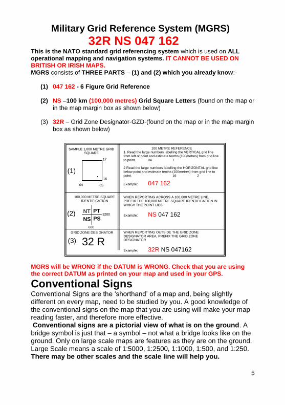
Military Grid Reference System (MGRS)
32R NS 047 162 This is the NATO standard grid referencing system which is used on ALL operational mapping and navigation systems. IT CANNOT BE USED ON BRITISH OR IRISH MAPS. MGRS consists of THREE PARTS – (1) and (2) which you already know:-
(1) 047 162 - 6 Figure Grid Reference
(2) NS –100 km (100,000 metres) Grid Square Letters (found on the map or
in the map margin box as shown below)
(3) 32R – Grid Zone Designator-GZD-(found on the map or in the map margin
box as shown below)
.
MGRS will be WRONG if the DATUM is WRONG. Check that you are using the correct DATUM as printed on your map and used in your GPS. Conventional Signs Conventional Signs are the ‘shorthand’ of a map and, being slightly different on every map, need to be studied by you. A good knowledge of the conventional signs on the map that you are using will make your map reading faster, and therefore more effective. Conventional signs are a pictorial view of what is on the ground. A bridge symbol is just that – a symbol – not what a bridge looks like on the ground. Only on large scale maps are features as they are on the ground. Large Scale means a scale of 1:5000, 1:2500, 1:1000, 1:500, and 1:250. There may be other scales and the scale line will help you.
NS
NT
(1)
(2)
(3)
100 METRE REFERENCE 1. Read the large numbers labelling the VERTICAL grid line from left of point and estimate tenths (100metres) from grid line to point. 04 7 2 Read the large numbers labelling the HORIZONTAL grid line below point and estimate tenths (100metres) from grid line to point. 16 2
Example: 047 162
WHEN REPORTING ACROSS A 100,000 METRE LINE, PREFIX THE 100,000 METRE SQUARE IDENTIFICATION IN WHICH THE POINT LIES
Example: NS 047 162
GRID ZONE DESIGNATOR
32 R WHEN REPORTING OUTSIDE THE GRID ZONE DESIGNATOR AREA, PREFIX THE GRID ZONE DESIGNATOR
Example: 32R NS 047162
SAMPLE 1,000 METRE GRID SQUARE
17
16
04 05
100,000 METRE SQUARE IDENTIFICATION
600
3200 PT
PS

6
Romers A Romer enables the user to accurately give the last figures of a grid reference to WITHIN 100 metres (1:50000 maps). Romers are found on the compass LW
and on protractors RA.
Reading a Grid Reference using a Romer. Check that you are using the correct Romer for the map scale being used, and that it reads in Metres NOT Yards.
Place the Romer onto the feature on the map, with the two Romer edges parallel to the grid lines as in the
example. The third and sixth figures are always rounded down to the lower value.
In this example the 6 figure grid reference is:
236 164
More examples: Wind Pump.
678 138 Triangulation pillar.
675 134 Mast.
671 131
6714
13
68
1 : 50 000 2468
4
6
8
10
2468
4
6
8
10
2468
4
6
8
10
2317
16
24
2468
4
6
8
10
4

7
To find or plot a grid reference using a Romer
Mast
896 327 Place the Romer in the correct grid square and move it so that the correct eastings and northings 100 metre figures are aligned with the grid lines. The grid reference may be exact or refers to the 100 m by 100 m square north east of the plotted position (as shown).
Romer accuracy. On the RA Protractor, there are Romers for 1:25,000, 1:50,000 and 1:100,000 scale maps. On 1:50,000 and 1:100,000 scale maps it is NOT POSSIBLE to subdivide the 100 metre marks on the Romer to get an 8 figure grid. Both maps are drawn to the best accuracy possible, but the accuracy is still only WITHIN 100 metres. On a 1:25,000 scale map the 100 metre marks on the Romer may be subdivided by eye to give the 4
th and 8
th figures of an grid 8
figure grid reference, thus giving an accuracy of plus or minus ten metres.
(GPS) Global Positioning Systems GPS is an excellent aid for finding your location accurately, but to display the
correct position you need to check that:- 1. The DATUM set on the GPS matches that PRINTED on the MAP. As you move around the world, remember to ALWAYS CHECK the map Datum, as it can and will change. 2. The Coordinate style is set to a format that is usable on the map, i.e. MGRS, UTM, Lat/Long, BNG etc. There are two handheld GPS types – Military specified (DAGR, SPGR, BOWMAN appliqué) and Civilian (GARMIN, MAGELLAN etc.) 1. If you have a military specified receiver, then you must ensure that it has its cryptographic keys loaded, as this will provide protection against electronic attack and guarantee that the position given is correct. 2. A civilian GPS is vulnerable to electronic attack so do NOT rely on it 100%. Check the given position regularly against the map or a military specification GPS. As a general rule, a civilian GPS is as accurate as an eight figure grid reference (ten metres) on all of maps you are issued. If you have any GPS questions contact your nearest Geo Cell (Geographic Staff). If you don’t know- ASK! - it’s their job to sort out your geographic problems!
8931
32
90
2468
4
6
8
10

8
Map Scale
Maps are produced in many different scales. The scale of a map is the ratio between a distance measured on a map and the same distance measured on the ground. Scale on a map, is shown as a ratio i.e. 1:50,000, and as a scale bar at the bottom of the map. Very occasionally nowadays, scale is seen on a map as a fraction i.e. 1/50,000 or as a statement i.e. 2 cm (meaning 2 cm equals 1 kilometre)
Below, are examples of ground and map (grid) distances on different scale maps.
Scale Ground Distance Map Distance
1:25,000 1 Km 4 cm
1:50,000 1 Km 2 cm
1:100,000 1 Km 1 cm
1:250,000 10 Km 4 cm
In the military, we must be able to use map scales to relate distances on the map to distances on the ground for movement (how far?), weapon positioning (range?), timings (how long?), etc. The two tactical military map scales are: 1:50,000 and 1:100,000 but on operations, various large scale maps or Image maps will be used with scales between 1:10,000, and 1:500. Besides looking at the scale and grid square size, always look in the margin at the scale bar which will give you an immediate idea of distances and sizes of features.
Map scale is ALWAYS shown on a map. Shown below is a British M726, 1:50,000 scale map with the ratio and scale lines shown.
© Crown copyright. All rights reserved ICG 1110100015347 2007

9
Estimating and measuring distance. As maps show a grid and have scale lines, it is possible to estimate or measure distances for use on the ground or on a map.
Distances are either DIRECT (straight line) or INDIRECT (measured along a road
or route). Over short distances the rise and fall of the ground has little or no effect unless the ground is mountainous.
Estimating direct distances on a map grid. Grid squares are one kilometre apart and just under one and half kilometres diagonally across the grid square.
Measuring direct distances using a scale line. If a distance is measured on a map, then the distance on the ground can be found by using the scale lines at the bottom of the map. Normally, the scale line distances are in kilometres and hundreds of metres i.e. 3.7 km or 3,700 m, but miles and nautical miles can be shown too.
M726 SCALE LINE
90 91 939286 87 88 894° 50'
1 0 1 2 3 4
1 0 1 2 3
KILOMETRES
STATUTE MILES
NAUTICAL MILES1 0 1 2
Estimation of east - west, north - south and diagonal
distances on a 1:50,000 scale map by use of grid lines
4 km 2 km = 4.5 km approx.3 x 1.5 km
3 km
1.5 km1.5 km
approx
© Crown copyright. All rights reserved ICG 100015347 2007

10
On a map, a straight line (direct) distance can be measured by ruler, lightweight compass, RA protractor, or as in the example below, a piece of paper. Lay the paper between the places marked on the map. Mark off both locations on the paper, then lay the paper on the scale line as shown, putting the right-hand mark against a whole division and the left-hand mark against the 100 m divided scale.
Measuring indirect distances (road, track or cross country)
An indirect distance can be measured by dividing a curved route into straight line sections or ‘bits’ as shown.
Continue the process until the full distance has been marked. Use the scale line to measure whole distance as before. Always re-measure the distance to check for mistakes.
Mark first bend,
A
Set start pointof paper here
B
S t r i p o f p a p e r
AB
A B
Pivot paper around B
S t
r i p
o f
p a
p e
r
A
B
Cpoint hereMark next
90 91 939286 87 88 894° 50'
1 0 1 2 3 4
1 0 1 2 3
KILOMETRES
STATUTE MILES
NAUTICAL MILES1 0 1 2A BDistance is 4.7 km
© Crown copyright. All rights reserved ICG 100015347 2007

11
Contours The brown lines drawn all over a map are called contours or contour lines.
Contours are not ground features that can actually be seen but are lines drawn on a map connecting points of the same height ABOVE MEAN SEA LEVEL.
This can be visualised as an island where the water is receding. Successive tide marks would then show as the contours.
Vertical Interval The difference in height between successive contours is called the VERTICAL INTERVAL (VI) or sometimes CONTOUR INTERVAL (CI). The vertical interval will be found in the map margin and may be different for different maps. On British M726 1:50,000 scale maps the VI is 10 metres but many military maps have a VI of 20 metres. Make sure you know the VI on the maps of your area of operations - there is a BIG DIFFERENCE between a VI of 10 metres and a VI of 20 metres!
Index Contours Looking at contours on a map allows you to:
1. Estimate heights above Mean Sea Level or to estimate height differences. 2. Visualise the slope of the ground. 3. Picture the shape of the ground.
Index contours are shown by using a thicker line than other contours. This can help when estimating heights quickly. On UK produced maps every fifth contour is an index contour. Usually index contours will have heights on them that read ‘uphill’ making it easier to
recognise high and low ground. On other countries maps this may not be the case – Check.
UPHILL
DOWN HILL
INDEX
CONTOUR 50
INDEX
CONTOUR 100

12
Slopes Contour SPACING shows the SLOPE of the ground.
Even Slope Evenly spaced contours.
The closer together the
contours are, then the steeper the slope. The further apart the contours are, then the more gentle
the slope.
Concave Slope As you go uphill, the ground becomes steeper and on the map the contours get closer together.
Convex Slope
The ground is steep at first but becomes gentler as you go uphill. On the map contours start close together but get wider apart as you go up the hill.
50
100
150
200
250
50
100
150
200
250
300
50
100
150
200
250
300

13
Irregular Slope
Usually, a slope will not be a simple profile and will be a combination of even, concave and convex slopes as shown here. Note the direction of the numbers written on the contours.
The Shape of the Ground
Contour PATTERN shows the SHAPE of the ground.
Below are simplistic views of the most common types of feature which you must be able to recognise both on the ground and on the map. Compare the picture of the feature, on the left, and the shape of contour patterns on the right. Study a map of your area to recognise more involved features and then go out on the ground and find them.
Hill Key contour pattern: Closed ring contours.
Ridge
Key contour pattern: Parallel contour lines with high ground in the middle, like a long narrow hill.
50
100
200
200
100
150
50
150
50
100
50
100
100

14
Saddle Key contour pattern: Two ring contour patterns with lower ground in between.
A saddle is, in fact, more ridge-like and elongated with lower ground creating a pass through the high ground.
Valley Key contour pattern: A series of hairpin bends with the bends pointing uphill.
Re-entrant Key contour pattern: As a valley but smaller. Usually a re-entrant is part of another feature - hill,
ridge, etc.. Called a ‘Draw’ in USA.
Spur Key contour pattern: Series of hairpin bends with the bends pointing downhill
(opposite of a valley). A series of interlocking valleys and spurs will have hairpin contours alternately pointing uphill then downhill - like your fingers spread on a table.
150
200
150
200
500
450
350
450
400
150
100
50
50

15
Bearings
Direction and North Direction can be given as a general compass direction: north (N), south (S), east (E), west (W), north-east, south-east, etc. Which way is north? If we can find north then we can find other directions. There are three norths. Magnetic North (MN). The compass needle points to magnetic north. Grid North (GN). The north-south (vertical) grid lines point to grid north at the top of the map. Grid north is not a place, just the direction of all the grid lines. True North (TN). This is the direction to the North Pole.
For normal map reading purposes we can ignore true north, we are only concerned with magnetic north and grid north.
Bearings** are directions measured CLOCKWISE from magnetic north and grid north. In the military, we give accurate directions using the MILS system. Degrees are not normally used, although it is useful to understand.
On the ground - A Magnetic Bearing is measured CLOCKWISE from Magnetic North using a compass to an object on the ground.
Using a map - A Grid Bearing is measured CLOCKWISE from Grid North using a protractor to a feature on the map.
GRID MAGNETIC ANGLE Magnetic north and grid north are in slightly different directions. In the military, the difference between magnetic and grid north is called the Grid Magnetic Angle (GMA, or G-M Angle). The GMA is usually found in the map
margin, with a small diagram to assist you in working out the GMA in mils. The GMA can be west or east. The GMA information in the map margin will tell you if GMA is west or east.
**In the USA, AZIMUTH has the same meaning as BEARING. So, Magnetic Azimuth is the same as Magnetic Bearing etc.
0 Degrees = 0 mils = North 90 Degrees = 1600 mils = East 180 Degrees = 3200 mils = South 270 Degrees = 4800 mils = West 360 Degrees = 6400 mils = North Note: Degrees and mils are equally accurate. See pp 42 and 43

16
GRID MAGNETIC ANGLE WEST
When GMA is west
To change a magnetic bearing to a grid bearing, subtract the GMA. To convert a grid bearing to a magnetic bearing, add the GMA.
MAG TO GRID - GET RID GRID TO MAG - ADD
GRID MAGNETIC ANGLE EAST
When GMA is east. To change a magnetic bearing to a grid bearing, add the GMA. To convert a grid bearing to a magnetic bearing, subtract the GMA.
MAG TO GRID - ADD GRID TO MAG - GET RID
GN MN
GMA 50 mils W
GN MN
GMA 50 mils E

17
Annual Change – Only apply if it makes a difference! This is an example of GMA information as shown in the margin of a map. The GMA in 2009 was 70 mils west. The year is now 2014 and the annual change is 4 mils East. This means that GMA West DECREASES by 4 mils east every year.
2009 to 2014 = 5 years 5yrs x 4 mils E= 20 mils E GMA 70 mils W – 20 mils E = 50 mils W GMA 50 mils west
Note: When working with a prismatic
compass and RA protractor, annual change has to be applied if it matters. However, the lightweight compass can only be read to 50 mils at best, so annual change can be ignored in the example above (GMA is still applied). Using the compass LW, if the annual change were to total 30 or 40 mils, then 50 mils should be applied to the GMA.
Compasses ARE affected by Iron and Steel etc. For compass reading accuracy, you must be the following distances away from ferrous metal (Iron, Steel etc.)
Armour & Artillery 50 Metres. Soft Skinned vehicles 20 Metres. Electrical/ Electronic equipment At least 5 Metres. Personal Weapons 3 Metres. Spectacles, watches. 1 Metre.
Wire Fences/Electricity Transmission Cables - As far away as possible – 20 metres minimum.
If you HAVE to take an accurate bearing then these are the minimum distances that a compass must be away from iron and steel. Your body will not shield your compass from your weapon. Of course you should never leave your
weapon, but you must accept the bearing you read will be out.
GN MN
70 mils W
MAGNETIC INFORMATION (2009) for centre of sheet
Annual change 4 mils E

18
CHAPTER 2: NAVIGATION EQUIPMENT
Lightweight Compass The Lightweight Compass (Silva but there are others) is graduated in mils
(degrees are secondary) and is night illuminated by a Gaseous Tritium Light Source (GTLS) (safety as per SUSAT). In the Red Arrow* should be the letters MN (underneath) for use in the world area roughly north of Mexico, the Mediterranean and Southern Japan. Anywhere else the needle may stick and the IA is to slightly tilt the compass and read as usual. It will work!
Compass parts
1. Base plate toe. 2. Radiation trefoil. 3. Direction of travel arrow. 4. Base plate. 5. Black setting line. 6. Red arrow* and orienting lines. 7. Compass needle with red North.
8. Base plate heel. 9. Three Romers. 10. Magnifying lens. 11. Two measuring scales. 12. Liquid filled compass capsule.* 13. Scale with 50 mil divisions. *If the capsule has a small bubble, it can be removed by gentle heat,(sun, radiator etc.) large bubbles cannot - the compass must be replaced immediately. Check that the red needle points North. The lanyard is NEVER worn around the neck. Attach to a
buttonhole or webbing etc. When the compass is not in use, store in a hard padded case.
Taking a magnetic bearing on the ground. Hold the compass LEVEL and point
the direction of travel arrow towards the target. Let the needle settle, then only turn the compass capsule until the red arrow in the orienting lines is underneath and parallel to the red end of the of the compass needle (red to red). Read the magnetic bearing against the black index line. In this case 800 mils.
0 8
10.
3.
4.
2.
9.
11.
7.
6.
13.
5.
12.
1.
8.

19
Plotting a magnetic bearing on the map. To plot a magnetic bearing as a grid bearing on the map. Ignore the compass needle when working on the map.
1. Apply GMA to the magnetic bearing on the black index line (- GMA west or + GMA east). From the previous example, 800 mils magnetic, becomes 700 mils grid. 2. Lay the side of the compass base plate onto the map, pivoting the heel end on your location. 3. Turn the whole compass until the red orienting lines are parallel with the north/south grid lines (red arrow towards north). IGNORE THE COMPASS NEEDLE.
4. A line drawn from your location along the side of the base plate towards the toe will point towards the target. To take a grid bearing from the map.
Ignore the compass needle when working on the map. 1. Lay the side of the compass base plate on the map on the line between your location and the target, with the direction of travel arrow pointing towards the target. 2. Turn the compass capsule until the red arrow and orienting lines are parallel with the north/south grid lines (red arrow towards north). 3. Read the grid bearing off the black index line. Setting a compass LW for a march, or to identify a feature.
1. Take the required grid bearing from the map with the compass LW and apply GMA (+ GMA west or - GMA east), to get the magnetic bearing. 2. Keep away from ferrous metal and hold the compass level.
3. Turn your body until the red end of the compass needle is centred in the red arrow and parallel to the orienting lines, red to red.
4. The direction of travel arrow will point towards the target on the ground. 5. IF YOU ARE MARCHING, choose a target, on line, to march onto which saves you from looking at the compass. Tree, river bend, rocky outcrop, building, etc. At night, choose an obvious star, on line, and check your compass every 10 minutes as stars move and another star may need to be chosen.
GRID
NORTH
OP 08
0402
06
10
GMA 100 mils west

20
The Prismatic Compass. The prismatic compass is mainly used as a sighting compass, it can be read to an accuracy of 10-20 mils.(depending on the model) For most map reading tasks the lightweight compass is sufficient however, some tasks require more accurate bearings for which the prismatic compass is used. The prismatic compass is a precise piece of equipment and should be stored in a padded case for protection. A protractor RA is needed to plot prismatic compass bearings on the map. For precise bearing work, the compass must be calibrated. See Army code 71874, Manual of map reading and land navigation, Apr. 2009.
The issued prismatic compass is graduated in mils and is night illuminated by a GTLS (safety as per SUSAT). A number of different models are in service, (M73 shown) however they all have similar features. If the compass reads erratically, or there is any doubt about the bearing, or it contains a bubble, it must be replaced immediately. See page 37 for an alternative compass.
Prismatic compass parts. 1. Compass lid comprising: a. Tongue with GTLS. b. Lid with protective bars. c. Sighting hair. 2. Black index setting line. 3. Compass box with liquid filled capsule enclosing the compass card and GTLS north point. The compass card is graduated in mils, directly for reading through the glass, and in reverse for reading through the prism. 4. Moveable glass plate with GTLS bar, which may be set for marching on a bearing. 5. Hinged prism assembly, which may be raised and lowered to focus and read. 6. Thumb ring.
1a.
1b.
1c.
3.
4.
6.
5.
2.
© Crown copyright. All rights reserved ICG 100015347 2007

21
Reading a magnetic bearing. Hold the compass level and look through the sighting slit on top of the prism and align the hairline on the lid with the target. At the same time look through the eyepiece at the reading on the compass card scale. When the scale stops moving, read the bearing against the hairline. Readings increase from RIGHT to LEFT as seen through the prism.
Prismatic compasses can be estimated to 10 mils (20 mils on some older models). If a compass bearing is found to be 40 mils different from a known bearing a check must be carried out on the compass. Check the compass against a number of known bearings, average the result and calculate a correction to be applied every time a bearing is read. A calibrated compass can be used to compare against.
Examples of Prismatic compass readings. A = 5800 mils. B = 3720 mils. C = 2880 mils. D = 1660 mils.
Reading a bearing at night Fold the lid forward and read the compass scale against the night lubber pin seen in the sighting slit. At night the compass can be read to 40 mils.
NIGHT LUBBER
PIN
58 38 3
16280

22
Setting the Prismatic compass for a march. 1. On a map, take the required grid bearing with the RA protractor and apply GMA to get the magnetic bearing. 2. Open the compass and fold the lid flat. 3. Turn the movable glass plate until the magnetic bearing is set on the black index setting line. In the picture the compass is set to 1000 mils. 4. Keep away from ferrous metal and hold the compass level. 5. Turn your body until the GTLS north bar on the compass card is directly underneath the GTLS bar on the top plate. The compass lid points towards your direction of travel. Pick an object, on line, to head towards, rather than looking down at the compass.
The protractor RA (Royal Artillery)
The protractor R.A. MILS/METRES MK1 (used with the Prismatic Compass) is graduated in 10 mils divisions and is used to measure and plot grid bearings on a map. The protractor is always aligned with the straight edge running on or parallel to the north-south grid lines. NOTE: If the ROMER holes are NOT in the correct place, then the Romer should be replaced.
Centre pointScale linesZero line
Romers
Outer scale values
0 – 3200 milsInner scale values
3200 – 6400 mils
© Crown copyright. All rights reserved ICG 100015347 2007

23
Plotting a grid bearing on a map To plot a bearing to the east (0–3200 mils).
1. Place the centre point on the known map location with the straight edge on the left and 0 mils towards grid north. 2. Align the zero line on or parallel to the north-south grid lines. 3. Read the given bearing on the outer scale (0–3200 mils), using either a pencil or attached cord to mark the direction to the target. To plot a bearing to the west (3200–6400 mils).
1. Place the centre point on the known map location with the straight edge on the right and 3200 mils towards grid north. 2. Align the zero line on or parallel to the north-south grid lines. 3. Read the given bearing on the inner scale (3200–6400 mils), using either a pencil or attached cord to mark the direction to the target.
Taking a grid bearing on a map to use as a magnetic bearing on the ground.
Draw a line between the two points then use the RA protractor as described above, to read the grid bearing from the scale. Apply GMA to turn the grid bearing into a magnetic bearing To use the magnetic bearing on the ground, to identify or march onto a feature: Turn body and compass together until the correct reading is shown through the compass sighting prism. Try to select an object to sight onto or to head towards.
Grid Bearing
1300 mils
Grid Bearing
5060 mils
Grid Bearing
1300 mils

24
CHAPTER 3: TECHNIQUES AND SKILLS
Relating Map and Ground
If your enemy lives where you are operating, then they have an advantage over you - they probably know the ground, You don’t.
However, if you study a map of the area it will help you to even things up. The processes below, will help you to relate map and ground. There is no such thing as a ‘’sense of direction’’- just good observational skills. For instance, noticing the direction of rivers,
streams, roads, and the ‘lie of the land’-hills, valleys, ridges, the shape of forest blocks, the direction of sand dunes, ice pressure ridges, etc. You DO need to know where you are (GPS can help!) Look around at everything you can see on the ground, so that when you look at your map all that you have seen MAY be able to be seen on the map. You are SHAPE MATCHING - shapes and features on the ground with what is on the map. Set your map either by compass, feature or linear feature, alignment, or by sun or
stars. Having set your map, study it and relate the map with the ground. Remember – SHAPE MATCHING and something you may already know, DDCRAPS.
Direction
When your map is set, directions on the ground will match the same directions on the map. In which direction have you been moving?
Distance
If you can roughly estimate distances on the ground, then those distances should be similar on the map. How far have you travelled? How far away/ How close is that feature?
Conventional
Signs
Features on the ground may well be shown by conventional signs on the map. Knowing the map legend will speed up your work.
Relief
The features that you see on the ground must be able to be matched with those on the map. What is in front/ behind/ to the sides? High / Low ground? Hills/ valleys/ re-entrants/ ridges/ etc?
Alignment
If you are lucky, features that line up on the ground will line up on the map. Look both at the ground and at the map!
Proximity
Nearness. Features close by each other on the ground have to be close by each other on the map. Check!
Shape
The shape of features on the ground will be replicated on the map. Woods, wood corners, bends in tracks/roads, lakes, (even hedge lines and walls on large scale maps).

25
Continued from the previous page - Relating Map and Ground.
Hopefully, you should now know where you are, and if you have to identify other positions and if you have a compass, use it to find them and then plot them onto your map. No compass? DDCRAPS again – but this time the place to be identified is away from you.
We have already set our map, but it is sensible to now ‘lock the map’ by drawing
a line from where you are to an obvious feature which can be seen on the ground too. This enables us to quickly reset the map and will help in finding other directions and locations. If you want to find a location on the ground, using
your set map, pivot a pencil on your map location and swing the front of the pencil until it lines up with the wanted feature on the ground. Then start thinking DDCRAPS. Not all of DDCRAPS is used every time. If there is no Alignment -
then there is no Alignment! If there is no Shape - then there is no Shape! However, any feature that does NOT fit means that your thoughts are wrong and your feature will be wrong!
‘’Well, all of DDCRAPS works except for the distance being a bit out’’ WRONG!
What has been described is not exact, and it must be practised often if you really want to be competent so get out on the ground and practise!
Having identified a feature on the ground and having studied the ground, look at the map.
Having identified a feature on the map and having studied the map, look at the ground.
Are we there yet? Having studied the map, look at the ground.
Where are we? Having studied the ground, look at the map.
Why? If you have confidence in your and other locations then any operations you carry out will be more effective! i.e. No more wrong locations!
You may think that the previous two pages are all very well, but what are you to do in featureless ground such as flat areas without much detail, or forest and jungle, even in poor visibility in fog, snow, or heavy rain? Relating map and ground together with DDCRAPS still applies, but much more emphasis must be put on direction and distance. By direction is meant-in which direction does this track go, and can those woods ahead be identified? In which direction and how far have we travelled / paced, since we last knew our exact location? Constantly question yourself as to locations and directions in the past, now, and what you intend in your immediate future. Pre-op exercises in keeping direction and pacing, together with understanding how forest and jungle are shown on your map will help in movement and, of course, nowadays, you should always have a GPS set with you- Don’t leave home without it!

26
Setting a map using a compass LW When a map is SET, it is easier to relate map and ground to find both your
location, other locations and to follow routes. A map can be set by using prominent ground features including line features, like roads, or by the sun (p 30), or by using a compass LW. The most basic method is to lay your compass LW on the map and make the red end of the compass needle parallel with the grid lines and pointing UP the map. To set a map using the compass LW: 1. Turn the lightweight compass capsule until the ‘N’ is set on the black index line.
2. Lay the compass along any north/south grid line on a map, with the direction of travel arrow pointing towards grid north.
3. Turn the map and compass together (as one fixed item), until the red end of the compass needle is centred in the red arrow and parallel to the orienting lines, red to red. N.B. For map setting, GMA (up to 100 mils) is ignored. To set the map with the compass if GMA is MORE than 100 mils . Note that
GMA is seldom as much as 100 mils, but it may be, and a new map must always be checked. GMA west. Carry out 1 and 2 as above. If the GMA is say, 200 mils west, turn the capsule to the LEFT so that 200 mils is set against the black index line. Turn the map and compass together, until the red end of the compass needle is centred in the red arrow and the letter ‘N’.
GMA east. Carry out 1 and 2 as above. If the GMA is say, 400 mils east, turn the capsule to the RIGHT so that 6000 mils is set against the black index line. Turn the map and compass together, until the red end of the compass needle is centred in the red arrow and the letter ‘N’.
GR
IDN
OR
TH
27
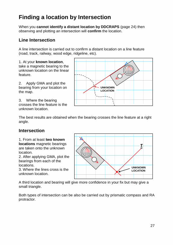
Finding a location by Intersection When you cannot identify a distant location by DDCRAPS (page 24) then observing and plotting an intersection will confirm the location.
Line Intersection A line intersection is carried out to confirm a distant location on a line feature (road, track, railway, wood edge, ridgeline, etc). 1. At your known location,
take a magnetic bearing to the unknown location on the linear feature. 2. Apply GMA and plot the bearing from your location on the map. 3. Where the bearing crosses the line feature is the unknown location. The best results are obtained when the bearing crosses the line feature at a right angle.
Intersection 1. From at least two known locations magnetic bearings
are taken onto the unknown location. 2. After applying GMA, plot the bearings from each of the locations. 3. Where the lines cross is the unknown location. A third location and bearing will give more confidence in your fix but may give a small triangle. Both types of intersection can be also be carried out by prismatic compass and RA protractor.
UNKNOWN
LOCATION
UNKNOWN
LOCATION

28
Plotting a back bearing onto a map A back bearing is plotted from a distant KNOWN position BACK towards your UNKNOWN location and is the basis of both line resections and resections. If you follow the methods below, THERE IS NO NEED TO ADD/SUBTRACT 3200 mils.
Plotting a back bearing with a compass LW. 1. Apply GMA to the magnetic bearing on the black index line (subtract GMA west or add GMA east), turning it into a grid bearing.
2. Lay the side of the compass base plate onto the map, pivoting the toe (front end) on the known location.
3. Pivot the whole compass until the red orienting lines are parallel with the north/south grid lines (red arrow towards north). IGNORE THE COMPASS NEEDLE.
4. A line drawn from the known location along the side of the base plate towards the heel of the compass will point towards your location.
Plotting a back bearing with a protractor RA.
Plotted Back Bearing of 1300 mils
1. Apply GMA to the magnetic bearing, turning it into a grid bearing. Place the centre point of the RA protractor on the known location with the straight edge on the opposite side to that for plotting a normal bearing (if the grid bearing is 1300 mils then the straight edge should be on the right).(1300 mils is in the same place on the protractor as 4500 mils) 2. Align the zero line on, or parallel to the north-south grid lines.
3. Read the given bearing on the scale, using either a pencil or attached cord to mark the direction of your location.

29
Confirming your location by Resection You should be able to identify your location by relating map and ground/DDCRAPS or by using GPS, but if you cannot, then observing and plotting a resection will confirm your location. If you do not know roughly where you are, then it is unlikely that a resection will help you. If you can see 2 or 3 objects identifiable both on the ground and on the map, then you may be able to find out where you are without a resection.
Line Resection A line resection is carried out to confirm your position on a line feature (road,
railway, track, wood edge, ridgeline, etc).
Resection 1. Find two or more features
that can be identified both on the map and on the ground, which ideally are at right angles to your rough location. 2. Take bearings to the features on the ground. 3. Apply GMA and plot the back bearings from the features on the map. 4. Where the lines cross is your position. A third bearing will give more confidence in your location but may give a location
in the centre of a small triangle. Both types of resection can also be carried out by prismatic compass and RA protractor, using the backward plotting method shown on the previous page.
1. Find a feature that can be identified both on the map and on the ground. 2. Take a bearing to the feature on the ground. 3. Apply GMA and plot the back bearing from the feature on the map. 4. Where the back bearing crosses the line feature is your position. The best result is obtained when the bearing cuts the line feature at right angles.
You are here
YOU ARE
HERE

30
Finding approximate direction by Sun and Stars
If you do not have a compass and have no idea of direction, then using the sun and the stars will help you to find any direction. The methods described on the following 4 pages are approximate but can also help to maintain direction when following a route. When North of Latitude 23.5
o N and South of Latitude 23.5
o S, the sun rises
roughly in the east and then continues to rise in the sky to midday and then sets roughly in the west. However, if you are working on or near the Equator, the sun is of little use for navigation except when it rises and when it sets – the rest of the time the sun will be too high in the sky to use for navigation.
When NORTH of
the equator, the sun rises towards the EAST and moves RIGHT to due SOUTH at midday
and then continues to move RIGHT
setting towards the WEST.
To find South when it is
not midday, the following method can be used as shown in the diagram. At arms length, an extended hand-span covers roughly one hour of sun movement.. In the Northern Hemisphere, at 11.00 hrs, South is 1 hand span right of the sun,
and at 1500 hrs 3 hand spans left of the sun.
Finding South using the Sun.

31
When SOUTH of
the equator the sun rises towards the EAST and moves LEFT to due NORTH at midday
then continues to move LEFT setting towards the West.
To find North when it is
not midday, the following method can be used as shown in the diagram At arms length, an extended hand-span covers roughly one hour of sun movement.. In the Southern Hemisphere, at 09.00 hrs, North is 3 hand spans left of the sun,
and at 1300 hrs 1 hand span right of the sun.
REMEMBER During Daylight saving Time (UK = British Summer time), you should take an hour off to get back to local time and then use hand spans
Finding North using the Sun.

32
Finding North using the Pole Star. North of the Equator, the Pole Star indicates the direction of North. To find the Pole Star, use the two pointer stars of the Great Bear, which extended in a line roughly four times their length (1½ hand spans) will show the Pole Star. As a check to ensure that the Pole Star has been correctly identified - draw a line in the sky from the tail star of the Plough, through the selected star , and if it is correct, then the line will extend onwards to the faint end star in the ‘W’ of Cassiopeia. From this, other direction can be found and a map can be set. The stars rotate anti-clockwise around the Pole Star which remains fixed. Star positions change through the night, but star patterns never change even if they are upside down to you!

33
Finding South using the Southern Cross and the Pointers. South of the Equator, there is no visible star at South. The DIRECTION of South can be indicated in the night sky by identifying the Southern Cross. Imagine the Southern Cross as a kite; extend the longer axis 4 times beyond the kite’s tail and the point reached will be the Southern Pole. This can be confirmed by identifying two brighter stars to one side of the Southern Cross – The Pointers. A line at right angles to the Pointers, and halfway between them, will meet the extended Southern Cross line at the pole. A line dropped from the pole will show the direction of South. The Pointers must always be identified as there are at least two false crosses in the southern sky. The stars rotate clockwise around the location of σ Octantis (can’t be seen). Star positions change through the night, but star patterns never change even if they are upside down to you!

34
CHAPTER 4: ROUTE SELECTION
Factors for Route Selection When planning a route ensure you know the correct start and finish locations. Before deciding your route, study the map in detail taking into account the key route planning factors. Route planning factors apply for all types of route whether by Helicopter, AFV, foot patrol, car or on adventurous training. The key factors for route selection are given by the mnemonic T R E C H. The
factors should be considered together, because each factor affects the others. For instance, the most direct route (fastest?) may not be possible if it can be seen from an enemy OP. Ease of navigation is great as long as the enemy doesn’t target your too obvious checkpoints.
T Time and Distance. Think how long and how far the route is?
R Relief and Going. Think about what the ground is like? Climb up
onto high ground, or stay in low ground? Cross difficult ground, or divert around?
E Ease of Navigation. Think about trying to make the route simple
to follow. Think about using checkpoints.
C Cover. Try to use cover for safety and surprise. Try to use dead
ground, stream beds, re-entrants, hedges and woods, etc.
H Hazards. Think about hazards such as enemy presence, minefields,
river crossings, weather conditions, etc. Try to minimise hazards.
When planning a route think about how each factor of TRECH may, in turn, affect the other factors. If time is limited, a shorter route may be needed or a faster method of movement. Does difficult or steep ground prevent travel through an area? Will it increase the time required to travel across it?
35
Other planning factors The key route planning factors are covered in TRECH, however there are other
factors to be considered. Information. Plan a route on a map before you start. Use all available up to date
information, including local knowledge, tactical intelligence, old patrol and weather reports. Health ,Fitness and numbers of persons involved. Personal fitness will affect
how far and fast you can travel. Are you all at the same fitness level? Take into consideration the weakest member of the section or individuals that are injured. Experience. Are the section experienced enough to cover the distance? Are they
capable of navigating the route in the time and conditions? Plan accordingly. Equipment. The weight that is carried will affect the speed that can be
maintained. Equipment Suitability. Is the vehicle suitable for the route? Are the personnel
properly equipped and clothed? Command. When a route has been selected try not to deviate from it unless
essential. If you do change the route, inform your superiors if possible. Rescue or casualty extraction will be planned using your recorded route.

36
Route Cards A route card describes the key details of your selected route. For a simple route, marking your route on a map may suffice. When the route is more difficult to navigate, it may be necessary to produce a route card. Always take a map with you for the unexpected. Nowadays also take a GPS so that you can get back on line. Do not forget to download any required route data at the end of your patrol.
Route card benefits 1. It concentrates your mind on the route and aids sensible planning. 2. It is a safety requirement that you leave your intentions with somebody. 3. It acts as a log and provides useful data during and after the journey. 4. Tactically it allows other patrols to know your location and duration of your patrol.
Making a route card
1. Calculate bearing along each leg. Bearings should have GMA applied and be written as magnetic bearings for use on the ground.
2. Measure the distance of each leg. 3. Estimate time to travel the route considering terrain, distance and prevailing weather. Add any remarks that may be an aid to navigation on the ground. Make sure your GPS has batteries and is set up with the correct datum and grid system.
Leg Mag
BearingDistanceFrom Grid
1
2
3
4
865 018
878 016
888 010
896 014
1350 m
1150 m
900 m
1000 m
1880 m
2270 m
1200 m
2560 m
/
/
/
/
1
2 3
4
Leg Mag
BearingDistance RemarksFrom Grid
1
2
3
4
865 018
878 016
888 010
896 014
1350 m
1150 m
900 m
1000 m
Corner of Track
Trig Pillar
1880 m
2270 m
1200 m
2560 m
/
/
/
/
1
2 3
4
16 min
16 min
23 min
18 min
Time
(minutes)
Leg Mag
BearingFrom Grid
1
2
3
4
865 018
878 016
888 010
896 014
1880 m
2270 m
1200 m
2560 m
/
/
/
/
1
2 3
4
© Crown copyright. All rights reserved ICG 100015347 2007
© Crown copyright. All rights reserved ICG 100015347 2007
© Crown copyright. All rights reserved ICG 100015347 2007

37
CHAPTER 5: FOLLOWING A ROUTE
Marching on a bearing The correct use of a compass provides the means of maintaining direction. In featureless terrain, or in bad visibility, you need to know the distance you have travelled.
Distance by Pacing Counting paces can be a reasonably accurate method of measuring distances on the ground, provided that the person pacing has calculated his/her step relative to the terrain and is well practised in pacing.
Pacing is effective in bad visibility or in close country such as forest or jungle. To calculate your pace, measure out 100 metres on level ground (a running track can be used). Using your normal stride count the number of paces taken to walk the 100 metres (a pace is counted every time the right heel hits the ground (double step)). This should be repeated, and an average result taken (most people take between 55 and 65 paces to cover 100 metres). The easiest way to pace a route is in 100 metre sections, starting the count again after each 100 metres. The number of 100 metre sections paced is recorded as you march.
Common methods used to record 100 metre sections are: slides or knots on a piece of cord, coins or pebbles in a pocket or a small tachometer.
© Crown copyright. All rights reserved ICG 100015347 2007
As you move up or down hill your paces will become shorter. Experiment on slopes to see how it affects your pacing over 100 metres and adjust your time/ distance covered accordingly.

38
Distance, Speed and Elapsed Time Calculating the time taken to complete a route is an aid to route selection. Elapsed time can also be used to estimate the distance travelled. A suitable method for vehicle moves, or movement on foot over open or otherwise easy terrain is to use the following:
D = S x T T = D
S = D
S T
Where D is DISTANCE in Kilometres.
S is SPEED in Kilometres per hour.
T is TIME in Hours.
Example: If the average speed of 4 kph was maintained over 2½ hours then; Distance travelled = S x T = 4 x 2.5 = 10 Km.
When moving on foot over more difficult terrain the following civilian method called Naismith’s Rules, can be used as a GENERAL GUIDE which you can adapt to your own circumstances - Number of personnel, fitness, loads to be
carried, tactical, etc.
Carrying light loads. 5 kph plus 1 minute per 10 metres climbed. Carrying medium and heavy loads. 4 kph plus 1½ minutes per 10 metres climbed. This system is adapted from the original ‘rules’ so that contours ‘upwards’ can be counted rapidly on a map with a 10 metre contour interval. It means that a map with 20 metre contour interval has to be counted as 5kph + 2mins.per 20 metres climbed and 4kph + 3mins. per 20metres climbed. It is NOT normal to
count contours downhill, as the slope can be counted as if on the flat. If the slope downwards is steep, then, of course, an allowance must be made for it.
The 10 metres is for maps with a 10 metre contour interval - you can rapidly count contours upwards
Following a planned route On operations it is important to be aware that an enemy is not stupid, and will use obvious routes and waypoints to attack you When starting on a route, to navigate effectively you should:- 1. Know where you are. 2. Have a second navigator to check the navigation. 3. Check and set map, having read route card. 4. Note the direction of travel, set compass, pick markers. 5. Note the start time. 6. Work out checkpoints/ waypoints and Estimated Times of Arrival (ETA).
7. In following a route, be aware of your surroundings and try to remember where you have come from.(in case you have to retrace your route) 8. Trust your compass. 9. On arrival at checkpoint, check your actual time against ETA.
.

39
If your route is obstructed by say, a lake, you can continue to march on the correct bearing, by looking for a prominent object
on the other side of the obstruction and moving around the lake until you arrive at
the chosen feature. If there is no suitable feature or the obstacle is large then ‘dog leg’ around the obstruction by Right angle Bearings. Don’t
change your compass setting but turn the compass through right angles, going left or right as necessary. Keep counting your paces so that the distances are correct.
An obvious feature such as a stream, power line or ridge which runs roughly parallel to your route can be used as a ‘handrail’ to guide you to a control point, or at least to the general area. In poor visibility, carefully pace the distance along the handrail.
If faced with crossing high ground , it may be better to follow a contour around the
feature rather than sweating up and down.
Never navigate directly to a specific point if it is on a line feature (track junction, etc.) Always aim off to one side so that you can
be certain that when you reach the line feature the junction is to the left.
Techniques for Navigation

40
Following a route in poor visibility To follow a route in poor visibility or at night, consider: 1. Do we need to go now or can we wait for better conditions or daylight? 2. Check location, check bearings and check distances.
3. Make use of sending forward a person as the leading marker and who will help check all bearings, back bearings and distances.
WHAT TO DO IF YOU ARE LOST (no GPS) Good map reading means that you will seldom become navigationally challenged (lost). If you do become temporarily lost then:
DON'T PANIC
STOP: Try to maintain morale and note the time.
THINK: Why do I think we are lost, what has changed?
Look at the ground. When was I last sure of my location? What mistakes might have been made? Wrong valley or path?
Having thought through your options, decide what to do.
Retrace your route to a known feature and relocate yourself. OR Go forward, looking for a major feature, which you can identify on your
map and then relocate yourself. There is no ‘sixth sense’ in map reading/navigation. There are only good memory and observational skills which can be developed, with practise.
When a feature is small and difficult to find, use a larger feature nearby to navigate to.
On the ground, the junctions may be difficult to find, especially at night, but the wood can be used as an attack point from which the
junctions can be found. Similar is a catching feature, usually linear,
often, but not always, beyond the target. When the catching feature is reached, the route can carefully be retraced to find the target. With experience, a catching feature
( if close to the target) can be used to bounce off.

41
CHAPTER 6: CONTINUATION TRAINING
Continuation training Navigating across different terrains in all weathers is part and parcel of being in the military. Understanding the ground in an area helps us fight better. Using these skills will enable us to function more efficiently. Map reading is part of nearly everything we do, whether on patrol, on adventure training or driving on holiday. Map reading training is never wasted when it is well prepared and involves practical outdoor exercises. By all means take and use a GPS set, but remember that GPS is a useful aid, just like a compass. Don’t try to use it in place of traditional map reading, use it with map reading. GPS has not replaced your map, yet! Any military training must involve map reading and navigation as part of an imaginative training program. Additionally, training periods must be set aside as preparation for MATT 5.
Adventure training The Military has always recognised the importance of adventure training, and in particular, trekking, climbing and mountaineering all involve map reading. These are activities that promote map reading as a skill and also practise navigating under testing conditions.
Orienteering ` Orienteering, as a sport, is an excellent method of improving map reading and navigation skills. Note however, it involves the use of maps at a much larger scale than normal tactical mapping. Many military training areas have permanent orienteering courses however, a simple course can be set up as long as time, planning, permission and preparation are allowed for.
Prepared by: MAPRIC, 942314260/01635-204260 Geospatial Information Wing, Royal School of Military Survey, Defence Intelligence Security Centre, Denison Barracks, Hermitage, Thatcham, Berkshire, RG18 9TP
Users noting errors or omissions are kindly requested to forward them to the RSMS.
Map information within this booklet has been reproduced from Ordnance Survey material with the permission of Ordnance Survey on behalf of the Controller of Her Majesty’s Stationary Office © Crown copyright. Unauthorised reproduction of OS material, infringes Crown copyright and may lead to prosecution or civil proceedings ICG 100015347 2007.

42
Notes: 1. The ‘FIREFLY’ Iris 50 prismatic compass (mils) (Dec 2010)
This inexpensive and rugged sighting compass is increasingly being used by individuals and units. It has not yet been tested to a military specification, but is well-known to yachtsmen, as a back-up hand-held compass. Its long-term ability to resist bubbles by changes in atmospheric conditions (ascending / descending by aircraft) is believed to be good, but it should be regularly checked. It reads very smoothly from LEFT to RIGHT. Calibrated, the Firefly can
be read to an accuracy of +/- 10 mils. Not calibrated, to +/- 20 mils. It has been used
from minus 40C to plus 40C successfully. The Firefly is slightly awkward to use when following a route, and it is suggested that a compass LW should be used for route following and as backup. Never put the
compass cord around your neck. Most Firefly compasses have GTLS so at night the compass MUST be put in a lightproof
pocket or case. To darken the GTLS, gently remove the rubber case and cover
the GTLS with tape to suit your needs, then refit the case and check before use.
Notes: 2. Mils enables us to easily adjust the fall of shot of indirect fire weapons
1 mil subtends 1 metre at 1 km. 10 mils subtend 10 metres at 1 km. 100 mils subtend 500 metres at 5 km. The MKA triangle is used to work out more complicated maths problems. M = Distance in METRES K = Range in KILOMETRES A = Angle in MILS
Using the triangle above for the triangle below: M = K x A, and K = M A,
and A = M K.
1 metre 1 km
1 mil
10 metres 1 km
10 mils
500 metres
5 km
100 mils
A K
M
M Distance in Metres
metres K Range in Kilometres
A Angle in mils

43
Continued from Page 42 For example; a weapon is fired at a target on a magnetic bearing of 1500 mils and a range of 4 km. Unfortunately, the round lands 300m LEFT of the target, so the correction needs to be RIGHT, but how far? Using the MKA triangle A = M K = 300 4 = 75 mils
In map reading, the ability to estimate distances is a useful tool in identifying features. Knowing the approximate height or width of a target, and using MKA and the mils divisions marked in military binoculars can help in this. For instance-How far away is a particular building which is 7mils (A) in width? If you estimate that the building is about 50 metres (M) in length then using MKA, the building is roughly 7 kilometres (K) away.
Notes: 3. Common Mils pattern in binoculars
Horizontal divisions = 10 mils (½
o Approx)
Vertical divisions = 5, 10 and 20 Mils ( ¼, ½ and 1o Approx)
4 km
(1500 + 75) = 1575 mils
On Target
300 metres
4 km 1500 mils
Fall of Shot
Target
M
K A
Whilst copyright is held by the MoD, you may freely use any material in this booklet UNCHANGED, if it is acknowledged. Ordnance Survey mapping must not be used in publications without a licence. (see note on page 41)

44
MAPRIC, RSMS.
OSTENDAMUS VIAM - WE SHOW THE WAY
Version 2.0 Dec2010 ABCBAMAW