mid-atlantic u.s. offshore carbon storage resource assessment...
TRANSCRIPT

Neeraj Gupta, Senior Research Leader/Chief ScientistInfrastructure and Environment, Battelle
Mid-Atlantic U.S. Offshore Carbon Storage Resource AssessmentDE-FE0026087
U.S. Department of EnergyNational Energy Technology Laboratory
Mastering the Subsurface Through Technology Innovation, Partnerships and Collaboration:Carbon Storage and Oil and Natural Gas Technologies Review Meeting
August 1-3, 2017

Presentation outline
• Project Overview & Organization
• Technical Status
• Accomplishments To-Date
• Lessons Learned
• Synergy Opportunities
• Project Summary
2
Project overview goals and objectives
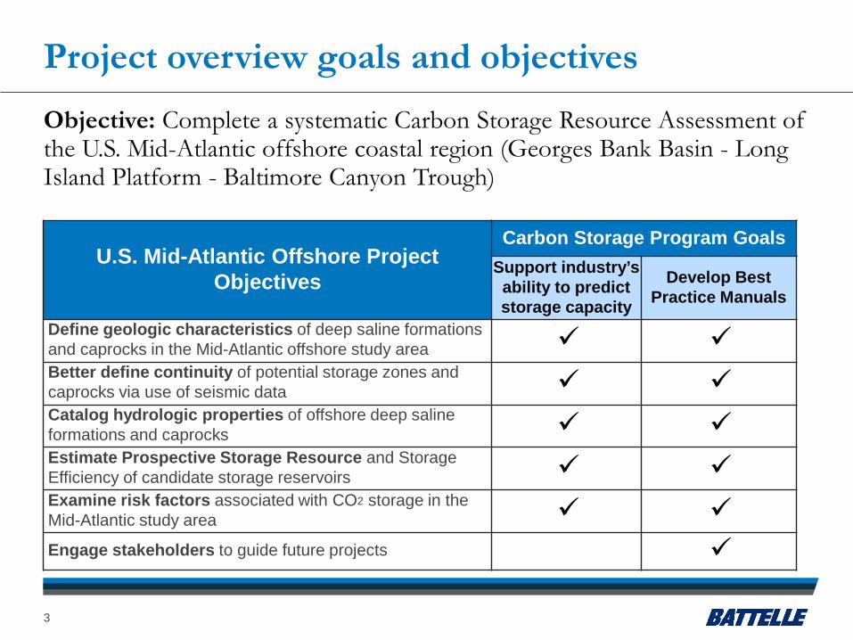
U.S. Mid-Atlantic Offshore Project Objectives
Carbon Storage Program GoalsSupport industry’s ability to predict storage capacity
Develop Best Practice Manuals
Define geologic characteristics of deep saline formations and caprocks in the Mid-Atlantic offshore study area Better define continuity of potential storage zones and caprocks via use of seismic data Catalog hydrologic properties of offshore deep saline formations and caprocks Estimate Prospective Storage Resource and Storage Efficiency of candidate storage reservoirs Examine risk factors associated with CO2 storage in the Mid-Atlantic study area Engage stakeholders to guide future projects
Objective: Complete a systematic Carbon Storage Resource Assessment of the U.S. Mid-Atlantic offshore coastal region (Georges Bank Basin - Long Island Platform - Baltimore Canyon Trough)
3

Project organization and team membersThe project consists of 8 tasks, with a diverse team of experts
responsible for project implementation
4

Project team – a seamless collaboration across multiple institute• Lamont Doherty Earth Obs. - Dave Goldberg, Angela Slagle, Will Fortin
• Delaware Geol. Surv. - Pete McLaughlin, Moji KunleDare, June Hazewski, Noam Kessing, David Wunsch
• Rutgers Univ. - Greg Mountain, Ken Miller, Stephen Graham, Alex Adams, John Schmelz, Kim Baldwin, David Andreasen, Chris Lombardy (deceased)
• Maryland Geol. Surv. - David Andreasen, Andy Staley, Katie Knippler, Richard Ortt
• Pennsylvania Geol. Surv. - Kristin Carter, Brian Dunst, Morgan Lee, Ryan Kassak, Danial Reese
• US Geol. Surv. - Guy Lang, Uri ten Brink
• Battelle - Lydia Cumming, Neeraj Gupta, Martin Jimenez, Andrew Burchwell, Joel Sminchak, Isis Fukai, Jit Bhattacharya, Kathryn Johnson, Judith Straathof, Bryan O'Reilly
• Advisors – Daniel Schrag (Harvard), Tip Meckel (TX BEG), David Spears (VA Geo. Surv.)

Technical statusProblem: Geologic resources available for CO2 storage are not well defined in U.S. State and Federally regulated offshore areas
• Near numerous CO2 point sources in northeast U.S. w/few onshore storage options
• Reduced risk to heavily populated areas and underground sources of drinking water
Solution: Characterize the Prospective Geologic CO2 Storage Resource of deep saline formations in the U.S. Mid-Atlantic offshore region
Study Area: ~170,993 km2
• Three sub-regions: GBB, Long Island Platform, BCT
• Storage potential in Cretaceous sandsinterbedded with and overlain by shale*
BCT Baltimore Canyon Trough GBB Georges Bank Basin
Stationary Sources of CO2 (U.S. DOE-NETL NATCARB v. 1502)
0 225 km
*Smith et al., 1976; Amato and Bebout, 1980; Slater, 2010; MRCSP, 2011 6

Technical Status: Task 2
Sample Inventory• ~2,300 core samples
• ~5,000 thin-sections
• ~97,000 drill cuttings
Data Compilation• ~2,500 log files
• >1,000,000 ft. of log data digitized
• 5,973 porosity & 5,729 permeability core data points* from 184 existing reports and publications
A large coordinated group effort was undertaken to categorize & preserve offshore samples and data for geologic characterization
WellIndustry Seismic Line
USGS Seismic Line
75 km
*Includes all raw and derived entries reported at all depths for 41out of 44 wells in the study area 7
Study area sample inventory & database content:
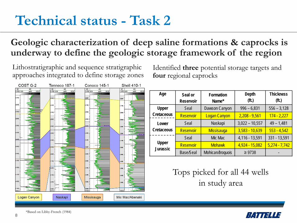
Technical status - Task 2Geologic characterization of deep saline formations & caprocks is underway to define the geologic storage framework of the region
Age Seal or Reservoir
Formation Name*
Depth(ft.)
Thickness (ft.)
Upper Cretaceous
Seal Dawson Canyon 996 – 6,831 556 – 3,128Reservoir Logan Canyon 2,208 - 9,561 174 - 2,227
Lower Cretaceous
Seal Naskapi 3,022 – 10,557 49 – 1,481Reservoir Missisauga 3,583 - 10,639 553 - 4,542
Seal Mic Mac 4,116 - 13,591 331 - 13,591Upper
JurassicReservoir Mohawk 4,924 - 15,082 5,274 - 7,742 Base/Seal Mohican/Iroquois ≥ 9738 -
*Based on Libby-French (1984)
Lithostratigraphic and sequence stratigraphic approaches integrated to define storage zones
Identified three potential storage targets and four regional caprocks
Tops picked for all 44 wells in study area
8
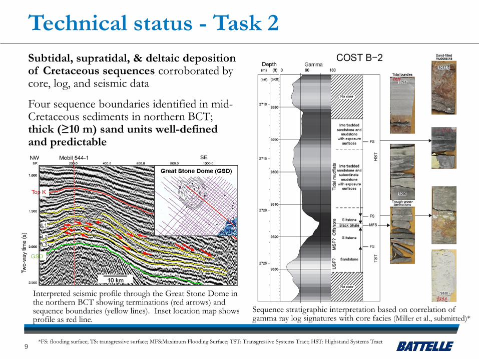
Subtidal, supratidal, & deltaic deposition of Cretaceous sequences corroborated by core, log, and seismic data
Four sequence boundaries identified in mid-Cretaceous sediments in northern BCT; thick (≥10 m) sand units well-defined and predictable
Sequence stratigraphic interpretation based on correlation of gamma ray log signatures with core facies (Miller et al., submitted)*
Interpreted seismic profile through the Great Stone Dome in the northern BCT showing terminations (red arrows) and sequence boundaries (yellow lines). Inset location map shows profile as red line.
Technical status - Task 2
*FS: flooding surface; TS: transgressive surface; MFS:Maximum Flooding Surface; TST: Transgressive Systems Tract; HST: Highstand Systems Tract9

Technical status – Task 3
Dense grid of existing USGS lines & newly released lines by BOEM & NAMSS*
Grid of newly released seismic lines (pink) available in the study area (from walrus.wr.usgs.gov/namss/search/)
Map showing the reprocessing plan for seismic lines in the study area. Approximately 2,000 km have been reprocessed to-date.
Seismic data is being reprocessed and used to constrain formation geometry, continuity, and geologic structures
Reprocessing 4,000 km of seismic with modern techniques to enhance resolution
*BOEM: Bureau of Ocean Energy Management; NAMSS: National Archive of Marine Seismic Surveys10
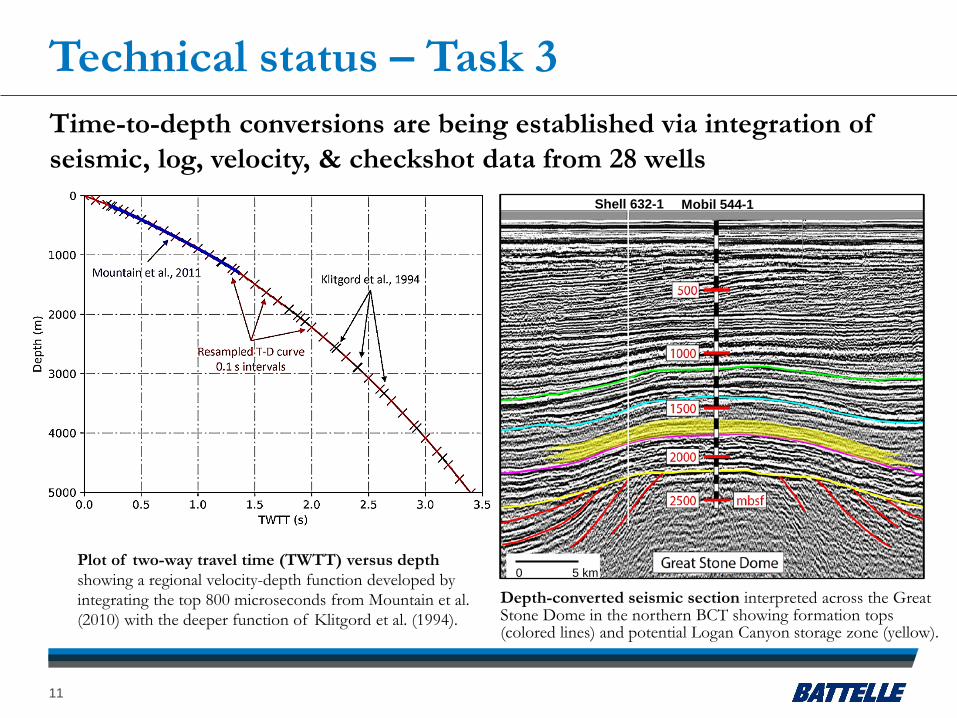
Technical status – Task 3Time-to-depth conversions are being established via integration of seismic, log, velocity, & checkshot data from 28 wells
11
0 5 km
Shell 632-1 Mobil 544-1
Plot of two-way travel time (TWTT) versus depth showing a regional velocity-depth function developed by integrating the top 800 microseconds from Mountain et al. (2010) with the deeper function of Klitgord et al. (1994).
Depth-converted seismic section interpreted across the Great Stone Dome in the northern BCT showing formation tops (colored lines) and potential Logan Canyon storage zone (yellow).
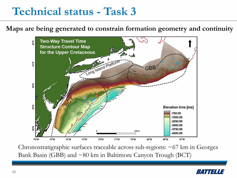
Chronostratigraphic surfaces traceable across sub-regions: ~67 km in Georges Bank Basin (GBB) and ~80 km in Baltimore Canyon Trough (BCT)
Technical status - Task 3
12
Two-Way Travel Time Structure Contour Map for the Upper Cretaceous
Maps are being generated to constrain formation geometry and continuity

Technical status – Task 4
Hydrologic and petrophysical properties of offshore deep saline formations and caprocks are being cataloged and characterized
13
y = 0.0056e0.3392x
R² = 0.58n = 4940.01
0.1
1
10
100
1000
10000
0 10 20 30 40
Cor
e Pe
rmea
bilit
y (m
D)
Core Porosity (%)
Logan Canyon
y = 0.0102e0.3196x
R² = 0.54n = 622
0 10 20 30 40Core Porosity (%)
Missisauga
y = 0.026e0.295x
R² = 0.53n = 1291
0 10 20 30 40Core Porosity (%)
Mohawk
Core porosity and permeability data indicate offshore deep saline formations of interest have storage reservoir potential
13

Technical status – Task 4Geologic samples have been selected for laboratory analysis to augment the hydrologic property characterization dataset
14
Up to 100 geologic core samples selected for (re)analysis: e.g. porosity, permeability, petrography, XRD
• Address data gaps• Verify & calibrate existing data
New and existing core data used to calibrate log data and calculate petrophysical properties for formations of interest
14
1: sandstone 2:mudstone
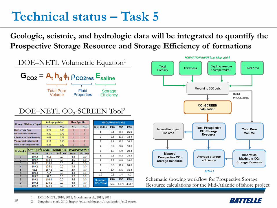
Technical status – Task 5Geologic, seismic, and hydrologic data will be integrated to quantify the Prospective Storage Resource and Storage Efficiency of formations
1. DOE-NETL, 2010; 2012; Goodman et al., 2011; 20162. Sanguinito et al., 2016; https://edx.netl.doe.gov/organization/co2-screen
GCO2 = At hg φt ρCO2res Esaline
Total Pore Volume
Fluid Properties
Storage Efficiency
GCO2 Results (Mt)
Grid Cell # P10 P50 P90
1 2.1 8.4 25.0
2 2.8 10.9 32.4
3 3.1 12.2 36.2
4 0.9 3.6 10.6
5 1.7 6.9 20.4
6 2.1 8.2 24.2
7 2.2 8.8 26.0
8 3.0 11.7 34.6
9 1.4 5.5 16.4
10 0.3 1.4 4.0
Summed CO2 Total
P10 P50 P90
564 1,873 4,517Schematic showing workflow for Prospective Storage Resource calculations for the Mid-Atlantic offshore project
15
DOE–NETL CO2-SCREEN Tool2
DOE–NETL Volumetric Equation1

Technical status – Task 6
Geological risk factors:• e.g. faults, basement structures,
seismic activity, slope stability
• Features to be portrayed on study area maps and geologic cross-sections
Long-term risk factors:• Integrity of confining layers:
mineralogy, thickness, hydrologic & geomechanical properties
• CO2 migration pathways & trapping mechanisms: reverse ‘Plinko’ flow simulations
Geologic and long-term risk factors associated with offshore CO2 storage in the Mid-Atlantic study area will be examined
16
Bathymetry map for the study area showing cross-section profiles of the shelf-slope transition in the GBB (H-H’), & southern BCT (C-C’).
-3,000-2,000-1,000
0
0 100 200Dept
h (m
AM
SL)
Distance (km)
C-C'
-3,000-2,000-1,000
0
0 100 200Dept
h (m
AM
SL) H-H'C
C’
H
H’
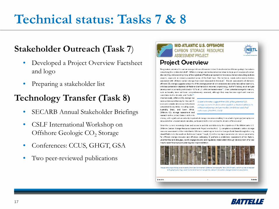
Technical status: Tasks 7 & 8
Stakeholder Outreach (Task 7)• Developed a Project Overview Factsheet
and logo
• Preparing a stakeholder list
Technology Transfer (Task 8)• SECARB Annual Stakeholder Briefings
• CSLF International Workshop on Offshore Geologic CO2 Storage
• Conferences: CCUS, GHGT, GSA
• Two peer-reviewed publications
17

Accomplishments to date• Completed detailed sample inventory and developed comprehensive geologic
database for study area
• Characterized key geologic properties of deep saline formations and caprocks, including: depth, thickness, porosity, permeability, sequence stratigraphy
• Surveyed and selected geologic core samples for laboratory analysis to address data gaps and calibration of existing data
• Evaluated and selected legacy seismic data for advanced reprocessing
• Established velocity-depth function for seismic time-to-depth conversions and have initial structure maps of formation continuity
• Began preliminary analysis of CO2 storage risk factors in study area
• Defined method and workflow for offshore Prospective CO2 Storage Resource calculations
• Prepared project fact sheet for stakeholder outreach and education
18
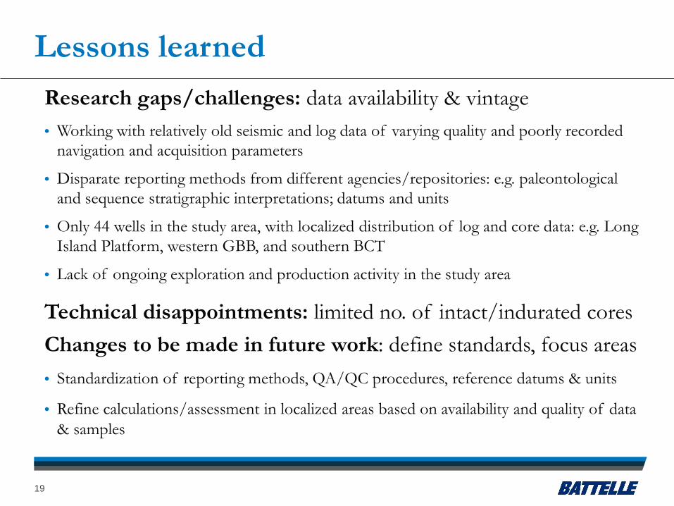
Lessons learnedResearch gaps/challenges: data availability & vintage• Working with relatively old seismic and log data of varying quality and poorly recorded
navigation and acquisition parameters
• Disparate reporting methods from different agencies/repositories: e.g. paleontological and sequence stratigraphic interpretations; datums and units
• Only 44 wells in the study area, with localized distribution of log and core data: e.g. Long Island Platform, western GBB, and southern BCT
• Lack of ongoing exploration and production activity in the study area
Technical disappointments: limited no. of intact/indurated cores Changes to be made in future work: define standards, focus areas • Standardization of reporting methods, QA/QC procedures, reference datums & units
• Refine calculations/assessment in localized areas based on availability and quality of data & samples
19

Synergy opportunities
Building on preliminary offshore characterization of MRCSP Program
Collaborating with other DOE Offshore Projects
• Data sharing/exchange with SOSRA
• Project technical advisors from SOSRA & Gulf Coast Projects
Adding to the international pool of offshore CCS information
• CSLF International Offshore Geologic Storage Workshops; World Bank - South Africa
20
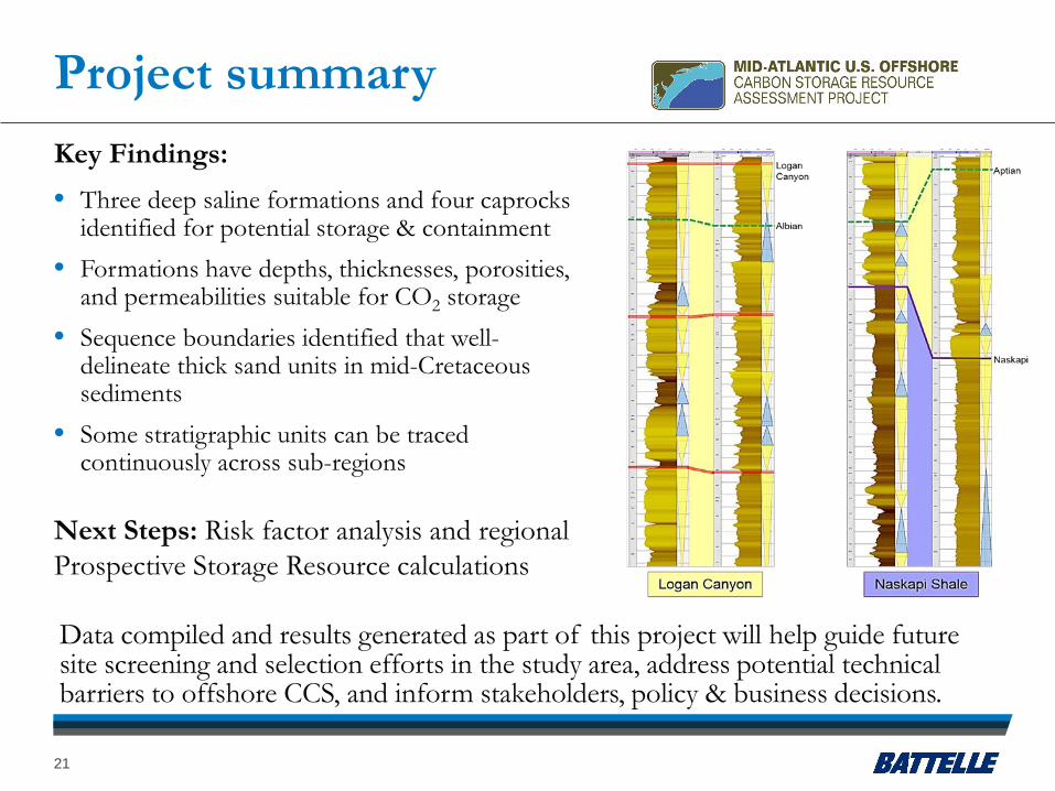
Project summary
Data compiled and results generated as part of this project will help guide future site screening and selection efforts in the study area, address potential technical barriers to offshore CCS, and inform stakeholders, policy & business decisions.
21
Key Findings: • Three deep saline formations and four caprocks
identified for potential storage & containment• Formations have depths, thicknesses, porosities,
and permeabilities suitable for CO2 storage• Sequence boundaries identified that well-
delineate thick sand units in mid-Cretaceous sediments
• Some stratigraphic units can be traced continuously across sub-regions
Next Steps: Risk factor analysis and regional Prospective Storage Resource calculations

Appendix
NOTE: Some of these slides are duplicated in the main presentation slide set
22

Benefit to the programThe project will establish a Prospective Storage Resource Assessment in offshore regions along the mid-Atlantic and northern states in the U.S. The key outcomes include: (1) a systematic carbon storage resource assessment of the offshore mid-Atlantic coastal region, (2) development of key input parameters to reduce uncertainty for offshore storage resource calculations and efficiency estimates, (3) evaluation of risk factors that affect storage resource potential, and (4) industry and regulatory stakeholder outreach to assist future projects.
Characterization of deep saline formation geologic and hydrologic properties, evaluation of risk factors, and estimation of Prospective Storage Resource at the P10, P50, and P90 percentiles for Mid-Atlantic offshore study area will contribute to the Carbon Storage Program’s effort to support industry’s ability to predict CO2storage capacity in geologic formations to within ±30 percent (Goal).
The overall workflow and results established by this project along with stakeholder outreach efforts will also aid in development of Best Practice Manuals for Site Screening, Selection, and Initial Characterization; Outreach; and Risk Analysis (Goal).
23
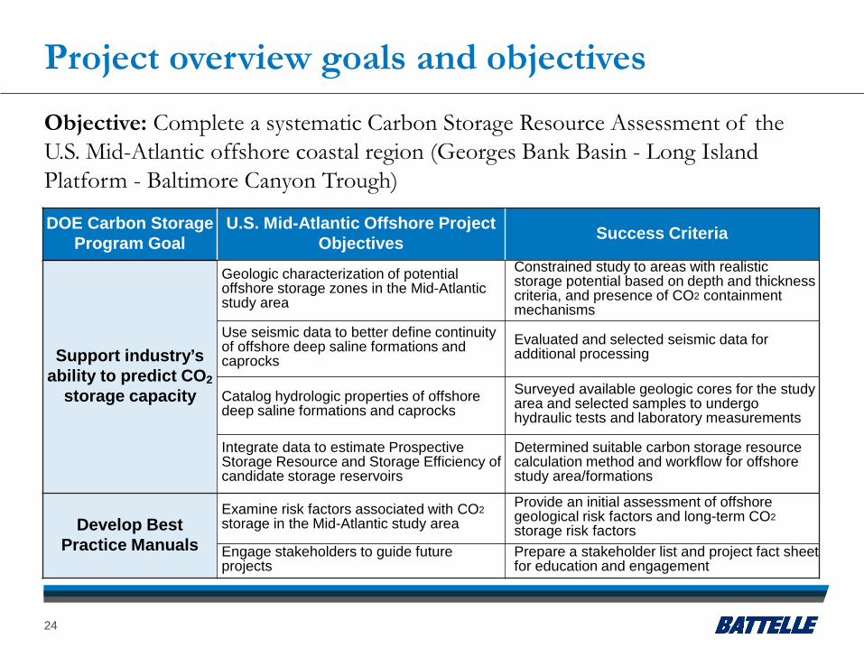
Project overview goals and objectivesObjective: Complete a systematic Carbon Storage Resource Assessment of the U.S. Mid-Atlantic offshore coastal region (Georges Bank Basin - Long Island Platform - Baltimore Canyon Trough)
DOE Carbon Storage Program Goal
U.S. Mid-Atlantic Offshore Project Objectives Success Criteria
Support industry’s ability to predict CO2
storage capacity
Geologic characterization of potential offshore storage zones in the Mid-Atlantic study area
Constrained study to areas with realistic storage potential based on depth and thickness criteria, and presence of CO2 containment mechanisms
Use seismic data to better define continuity of offshore deep saline formations and caprocks
Evaluated and selected seismic data for additional processing
Catalog hydrologic properties of offshore deep saline formations and caprocks
Surveyed available geologic cores for the study area and selected samples to undergo hydraulic tests and laboratory measurements
Integrate data to estimate Prospective Storage Resource and Storage Efficiency of candidate storage reservoirs
Determined suitable carbon storage resource calculation method and workflow for offshore study area/formations
Develop Best Practice Manuals
Examine risk factors associated with CO2storage in the Mid-Atlantic study area
Provide an initial assessment of offshore geological risk factors and long-term CO2storage risk factors
Engage stakeholders to guide future projects
Prepare a stakeholder list and project fact sheet for education and engagement
24

Organization chart
25

Gantt chartBudget Period BP1 BP2
Task Name FY2016 FY2017 FY2018Q1 Q2 Q3 Q4 Q1 Q2 Q3 Q4 Q1 Q2 Q3 Q4
Task 1: Project Management & Planning1.1 Update Project Mgmt. Plan 1.2 Project Management1.3 Project Controls1.4 NEPA Reporting
Task 2: Offshore Geologic Characterization2.1 Data Compilation and Synthesis2.2 Correlation of Seismic Data with Well Logs2.3 Well Log Analysis2.4 Formation Maps and Cross-Sections
Task 3: Seismic Evaluation3.1 Seismic Processing3.2 Seismic Interpretation3.3 Integration of Seismic Data
Task 4: Hydrologic Properties Characterization4.1 Hydrologic Props Data Collection & Testing4.2 Calibration of Logs with Test Data.4.3 Num. Simulation Valid. Runs for Loc.Areas
Task 5: Carbon Storage Resource Calculations5.1 Local Resource Calculations5.2 Regional Resource Calculations
Task 6: Risk Factors for Mid-Atlantic Offshore Areas6.1 Offshore Geological Risk Factors6.2 Long Term Storage Risk Factors
Task 7: Stakeholder Education & Engagement7.1 Mid-Atlantic Stakeholder Education7.2 Industrial Stakeholder Activities7.3 Technology Communication Activities
Task 8: Reporting and Tech Transfer - milestone - work completed to-date- duration of task
26
Bibliography
Miller, K.G., Browning, J.V., Sugarman, P.J., Monteverde, D.H., Andreasen, D.C., Lombardi, C., Thornburg, J., Reinfelder, Y., and Kopp, R.E., 2017, Lower to mid-Cretaceous sequence stratigraphy and characterization of CO2 storage potential in the Mid-Atlantic U.S. Coastal Plain. Journal of Sedimentary Research, v. 87, p. 609-629, available at: http://eps.rutgers.edu/images/17-MillerCCS.full.pdf
Miller, K.G., Lombardi, C., Browning, J.V., Schmelz, W.J., Gallegos, G., and Mountain, G.S., Back to basics of sequence stratigraphy: Early Miocene and Mid Cretaceous examples from the New Jersey paleoshelf. Journal of Sedimentary Research(provisionally accepted June 27, 2017).
27