microwave harmonic generation by ferrimagnetic crystals
TRANSCRIPT
Microwave Harmonic Generation by Ferrimagnetic CrystalsD. D. Douthett, I. Kaufman, and A. S. Risley Citation: Journal of Applied Physics 32, 1905 (1961); doi: 10.1063/1.1728261 View online: http://dx.doi.org/10.1063/1.1728261 View Table of Contents: http://scitation.aip.org/content/aip/journal/jap/32/10?ver=pdfcov Published by the AIP Publishing Articles you may be interested in Harmonic Generation in a Microwave Discharge Phys. Fluids 8, 1534 (1965); 10.1063/1.1761450 Pulsed Ferrimagnetic Microwave Generator J. Appl. Phys. 31, S400 (1960); 10.1063/1.1984763 Harmonic Generation in a Ferrimagnetic Disk J. Appl. Phys. 31, S97 (1960); 10.1063/1.1984618 Microwave Resonance in Hexagonal Ferrimagnetic Single Crystals J. Appl. Phys. 30, S175 (1959); 10.1063/1.2185873 Convenient Microwave Harmonic Generator Rev. Sci. Instrum. 27, 174 (1956); 10.1063/1.1715512
[This article is copyrighted as indicated in the article. Reuse of AIP content is subject to the terms at: http://scitation.aip.org/termsconditions. Downloaded to
] IP: 155.33.16.124 On: Sun, 23 Nov 2014 06:03:04
JOURNAL OF APPLIED PHYSICS VOLUME 32, NUMBER 10 OCTOBER, 1961
Microwave Harmonic Generation by Ferrimagnetic Crystals
D. D. DOUTHETT, 1. KAUFMAN, AND A. S. RISLEY
SPace Technology Laboratories, Canoga Park, California
(Received March 13, 1961)
The experimental behavior of isotropic ferrimagnetic insulators in second harmonic generation at microwave frequencies has been investigated and compared with the behavior predicted by the equations of motion with Landau-Lifshitz and with Bloch-Bloembergen damping. In general, a close agreement between experiment and theory was found. The experiments were carried out with small samples of single-crystal manganese ferrite, YIG, and other ferrimagnetic materials. Since harmonic generation results from asymmetries in the precessional orbit, measurements were made with disk-shaped specimens in which the demagnetizing fields create the asymmetry. The technique employed a cavity simul-
I. INTRODUCTION
M OST applications of ferrimagnetic materials to microwaves utilize the linear anisotropic behavior
resulting from their gyromagnetic properties. The subject of this paper is second harmonic generation, which is a direct consequence of one of the nonlinear effects present in ferrimagnetic materials under particular experimental conditions.
Frequency doubling in ferrites has been demonstrated experimentally and analyzed by a number of investigators.I-6 In previous experimental work, the major aim was to achieve as much harmonic power as possible. Ferrites of various compositions, shapes, and sizes were placed into waveguides and excited with high-intensity microwave power. By this technique as high as 8 kw of second harmonic power was obtained from 32 kw of 9-kMc input.2 This result represents a significant achievement.
While these earlier experiments demonstrated that ferrites are capable of efficient harmonic generation, they did not lend themselves to quantitative comparison with results expected from theory. Qualitatively, there was no consistent correlation between the relative amounts of 2w power with the output predicted by a theoretical figure of merit M./ !lH.
This paper compares the experimental behavior of ferrimagnets with the predictions of a phenomenological theory. In particular, we studied the influence of material linewidth, magnetization, dc magnetic field, and drive level, on second harmonic magnetization. (The effect of magnetocrystalline anisotropy on the results reported here is small and will be neglected.) It was felt that experiments with small samples could
1 W. P. Ayres, P. H. Vartanian, and J. L. Melchor, Phys. Rev. 100, 1791 (1955).
2 J. H. Melchor, W. P. Ayres, and P. H. Vartanian, Proc. Inst. Radio Engrs. 45, 644 (1957).
3 E. Stern and P. S. Pershan, presented at Symposium on the Role of Solid State Phenomena in Electric Circuits, Polytechnic Institute of Brooklyn, Brooklyn, N. Y., April 23, 1957.
4 J. E. Pippin, Proc. 1. R. E. 44, 1054 (1956). 6 R. L. Jepsen, Gordon McKay Laboratory, Air Force Cam
bridge Research Center, 1958. 6 W. P. Ayres, IRE Trans. Microwave Theory Tech. MTT-7,
62 (1959).
taneously resonant to 8.5 and 17 kMc. Absolute values of field intensities and magnetizations were computed from absolute power measurements. A figure of merit F for a ferrimagnet is defined. In a practical 2w generator the output power P 2w is expected to vary as the product F2Pi 2, where Pi is the input w power. In comparing materials at ferrimagnetic resonance (FMR), F should vary as xo". This was verified experimentally, even at high drive levels. At constant frequency and drive level F should be nearly independent of Hdc . Only slight deviations from this were found at low drive levels.
provide the maximum amount of basic information, unobscured by propagation and variable coupling effects. We used small, disk-shaped samples, located in a cavity simultaneously resonant to 8.5 and 17 kMc. The experimental arrangement allowed absolute measurements of exciting field, absorption, and second harmonic magnetization. Throughout this text, we have used mks units, with B=JLoH+M, where JLo=4?rX 10-7 him.
A portion of this work was reported earlier in an oral paper. 7
II. THEORY
It can be shown from a geometrical argument4 that if the magnetization precesses asymmetrically, it will contain harmonics of the fundamental frequency. In discussions of second harmonic generation, a linearly polarized, rather than a circularly polarized, driving field often has been stressed as the means for inducing a noncircular precession.
In the following we show, from an analysis of the freely precessing magnetization, that the internal fields resulting from shape anisotropy alone may be very effective in producing a noncircular precession.
In addition, we consider a uniformly excited diskshaped specimen with magnetic losses, and calculate the fundamental absorption and second harmonic magnetization for this case.
Finally, a detailed discussion is given in which a figure of merit for 2w generation by a lossy nonlinear material is derived.
The process of generation of rf fundamental and harmonic frequency components of the magnetization in a ferrimagnet can be described by an analysis of the equation of motion of the magnetization. Including an appropriate damping term, this equation is
dM/dt='Y(MXH)+('Ya/M.)[MX (MXH)]. (1)
M is the instantaneous magnetization, H is the total internal magnetic field, 'Y is the gyromagnetic ratio for an electron, a(~!lH/Ho) is the Landau-Lifshitz damping parameter, and M. is the saturation magnetization.
7 I. Kaufman, A. S. Risley, and D. D. Douthett, Bull. Am. Phys. Soc. 5, 297 (1960).
1905 [This article is copyrighted as indicated in the article. Reuse of AIP content is subject to the terms at: http://scitation.aip.org/termsconditions. Downloaded to
] IP: 155.33.16.124 On: Sun, 23 Nov 2014 06:03:04
1906 DOUTHETT, KAUFMAN, AND RISLEY
RESONANT CIRCUIT STRUCTURL
1 p. """" P2 tu(\NV\
'- -(0)
(b)
Igi '\OO::VOLUME OF
NONLINEAR MATERIAL
NONLINEAR MATERIAL
OUTPUT LOAD
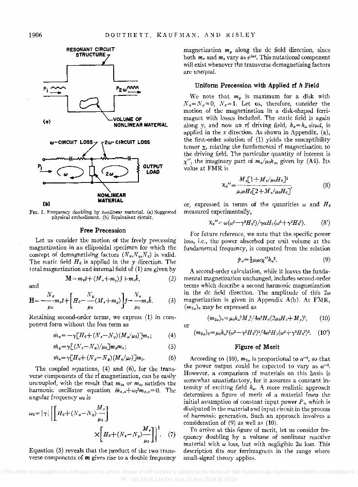
FIG. 1. Frequency doubling by nonlinear material. (a) Suggested physical embodiment. (b) Equivalent circuit.
Free Precession
Let us consider the motion of the freely precessing magnetization in an ellipsoidal specimen for which the concept of demagnetizing factors (N f/:,N y,N.) is valid. The static field H 0 is applied in the y direction. The total magnetization and internal field of (1) are given by
M=m",t+(M.+my)J+mzk, (2)
(3)
Retaining second-order terms, we express (1) in com-
magnetization my along the dc field direction, since both m" and m. vary as ei"'t. This nutational component will exist whenever the transverse demagnetizing factors are unequal.
Uniform Precession with Applied rf h Field
We note that my is maximum for a disk with N,,=Ny=O, N.= 1. Let us, therefore, consider the motion of the magnetization in a disk-shaped ferrimagnet with losses included. The static field is again along y, and now an rf driving field, h,,= h", sinwt, is applied in the x direction. As shown in Appendix, (a), the first-order solution of (1) yields the susceptibility tensor X, relating the fundamental rf magnetization to the driving field. The particular quantity of interest is x", the imaginary part of mi,uoh"" given by (A4). Its value at FMR is
xo" M.[l +M.I,uoHoJl
,urtXHo[2+ M.I,uoHoJ' (8)
or, expressed in terms of the quantities wand Ho measured experimentally,
xo"=w(w2-r2Ho2)/raHo(w2+r2Ho2). (8')
For future reference, we note that the specific power loss, i.e., the power absorbed per unit volume at the fundamental frequency, is computed from the relation
(9)
A second-order calculation, while it leaves the fundamental magnetization unchanged, includes second-order terms which describe a second harmonic magnetization in the dc field direction. The amplitude of this 2w magnetization is given in Appendix A(b). At FMR, (m2",)O may be expressed as
(10) ponent form without the loss term as or
rh",= -r[Ho+(N.-Ny)(M.I,uo)Jm.; (4)
rhy=r[(N.-N",)/,uo]m"m.; (5)
rh.=r[Ho+(N"-Ny)(M./,uo)]m,,. (6)
The coupled equations, (4) and (6), for the transverse components of the rf magnetization, can be easily uncoupled, with the result that m", or m., satisfies the harmonic oscillator equation m",.+wo2m"".=O. The angular frequency Wo is
Wo= 1"11 {[ Ho+(Nx- Ny):']
X[Ho+(Nz-N II):"Jr. (7)
Equation (5) reveals that the product of the two transverse components of m gives rise to a double frequency
Figure of Merit
According to (10), m2w is proportional to a-2, so that the power output could be expected to vary as a-4•
However, a comparison of materials on this basis is somewhat unsatisfactory, for it assumes a constant intensity of exciting field h.,. A more realistic approach determines a figure of merit of a material from the initial assumption of constant input power Pi, which is dissipated in the material and input circuit in the process of harmonic generation. Such an approach involves a consideration of (9) as well as (10).
To arrive at this figure of merit, let us consider frequency doubling by a volume of nonlinear reactive material with w loss, but with negligible 2w loss. This description fits our ferrimagnets in the range where small-signal theory applies.
[This article is copyrighted as indicated in the article. Reuse of AIP content is subject to the terms at: http://scitation.aip.org/termsconditions. Downloaded to ]
IP: 155.33.16.124 On: Sun, 23 Nov 2014 06:03:04
MICROWAVE HARMONIC GENERATION 1907
We define the following two material parameters:
r=Zp.,/h,}, (11) and
(lZ)
The factor Zw appears in (12) to be consistent with the more general case presented elsewhere. 8
We assume a doubly resonant circuit configuration, as shown in Fig. 1. This diagram suggests a metallic circuit structure, although such is not necessary. It is also possible to allow the nonlinear material to act as a self-resonant circuit.
We further postulate that there is no "loading" of the input, or w circuit, by the Zw-output power. This approximation is valid for conversion efficiencies up to about 10%. For simplicity, we also assume that the material is uniformly excited, and couples out energy uniformly. To relate directly to ferrimagnets, the following discussion is in terms of magnetic fields and magnetiza tions.
The w power Pi, dividing into circuit and material losses, is given by
P i =!Lh.,2+P.,V=!(L+rV)h.,2, (13)
where L is related to the total w-circuit structure loss. Acting as a source, m2., gives rise to an h2., field in
circuit and material. For maximum power output, both wand Zw circuits are tuned to resonance. Then m2., and the generated h2., will be in phase. The average power developed by the material is then
(14)
We assume that the 2w structure is not loaded by an output circuit. P 2., will then be dissipated in the Zwresonant structure. Thus,
(15)
where R 2., is a coupling "impedance" that relates cavity field h2., (at the material) to P 2.,.
Combining (11)-(15), we find that
P2W=~Pi2k22(_V_)2. R 2., rV+L
(16)
If r V»L, then (16) approaches the value
P2"~ (Z/R2.,)Pi2(k2/r)2. (17)
[If the cavity is properly loaded by an output circuit, the output power is one-fourth of (17).J The ratio k2/r is determined entirely by material properties. We therefore define F= k2/r= figure of merit for Zw generation.
In particular, for the ferrimagnetic disk, oriented and driven as described above, the theoretical value of F at FMR is
w(m2w)O h'IMs Fo=--= . (18)
(Pw)o 2w.uoa[ (M./ .uo)2+4(w/y )2Jf
8 1. Kaufman, presented ':"at Conference on Electron Tube Research, Seattle, July 1, 1960 (to be published).
III 2111 h-FIELD h-FIELD -+----+-!
X J-y
Hdc ---...... SPECIMEN ON
POLYSTYRENE DISK
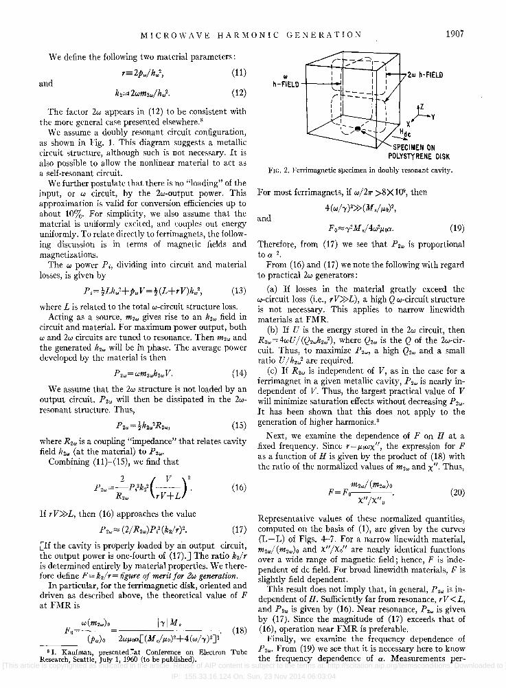
FIG. 2. Ferrimagnetic specimen in doubly resonant cavity.
For most ferrimagnets, if w/Z7r >8X 10⁹, then
4(wh )2» (Ms/ .uO)2, and
(19)
Therefore, from (17) we see that P 2., is proportional to 0::-2•
From (16) and (17) we note the following with regard to practical Zw generators:
(a) If losses in the material greatly exceed the w-circuit loss (i.e., r V»L), a high Q w-circuit structure is not necessary. This applies to narrow linewidth materials at FMR.
(b) If U is the energy stored in the Zw circuit, then R2., = 4w U / (Q 2wh2.,2) , where Q2w is the Q of the Zw-circuit. Thus, to maximize P2." a high Q2w and a small ratio U/h 2.,2 are required.
(c) If R 2., is independent of V, as in the case for a ferrimagnet in a given metallic cavity, P 2., is nearly independent of V. Thus, the largest practical value of V will minimize saturation effects without decreasing P 2.,.
It has been shown that this does not apply to the generation of higher harmonics. 8
N ext, we examine the dependence of F on H at a fixed frequency. Since r=.uowx", the expression for F as a function of H is given by the product of (18) with the ratio of the normalized values of m2., and x". Thus,
m2w! (m2w)O F=Fo·---
x" /x" 0
(20)
Representative values of these normalized quantities, computed on the basis of (1), are given by the curves (L-L) of Figs. 4-7. For a narrow linewidth material, m2w/(m2w)O and x"/xo" are nearly identical functions over a wide range of magnetic field; hence, F is independent of dc field. For broad linewidth materials, F is slightly field dependent.
This result does not imply that, in general, P2w is independent of H. Sufficiently far from resonance, r V < L, and P 2w is given by (16). Near resonance, P 2w is given by (17). Since the magnitude of (17) exceeds that of (16), operation near FMR is preferable.
Finally, we examine the frequency dependence of P 2w' From (19) we see that it is necessary here to know the frequency dependence of 0::. Measurements per-
[This article is copyrighted as indicated in the article. Reuse of AIP content is subject to the terms at: http://scitation.aip.org/termsconditions. Downloaded to ]
IP: 155.33.16.124 On: Sun, 23 Nov 2014 06:03:04
1908 DOUTHETT, KAUFMAN, AND RISLEY
B A
o o ...,
®
W-MONITOR
®
@
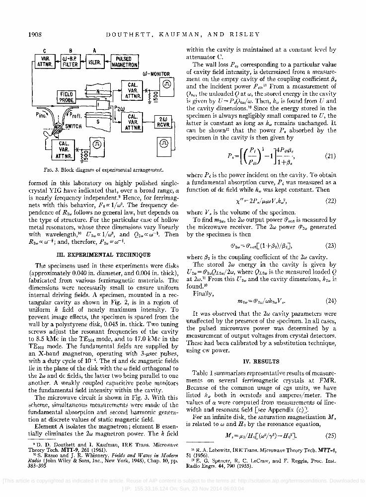
FIG. 3. Block diagram of experimental arrangement.
formed in this laboratory on highly polished singlecrystal YIG have indicated that, over a broad range, a is nearly frequency independent.9 Hence, for ferrimagnets with this behavior, F 0 ex 1/ w2• The frequency dependence of R 2w follows no general law, but depends on the type of structure. For the particular case of hollow metal resonators, whose three dimensions vary linearly with wavelength,lO U 2w ex 1/w3, and Q2w ex w-t . Then R 2w ex w-!; and, therefore, P 2w ex w-~.
III. EXPERIMENTAL TECHNIQUE
The specimens used in these experiments were disks (approximately 0.040 in. diameter, and 0.004 in. thick), fabricated from various ferrimagnetic materials. The dimensions were necessarily small to ensure uniform internal driving fields. A specimen, mounted in a rectangular cavity as shown in Fig. 2, is in a region of uniform h field of nearly maximum intensity. To prevent image effects, the specimen is spaced from the wall by a polystyrene disk, 0.045 in. thick. Two tuning screws adjust the resonant frequencies of the cavity to 8.5 kMc in the TElol mode, and to 17.0 kMc in the TEo12 mode. The fundamental fields are supplied by an X-band magnetron, operating with 3-tLsec pulses, with a duty cycle of 10-4
• The rf and dc magnetic fields lie in the plane of the disk with the w field orthogonal to the 2w and dc fields, the latter two being parallel to one another. A weakly coupled capacitive probe monitors the fundamental field intensity within the cavity.
The microwave circuit is shown in Fig. 3. With this scheme, simultaneous measurements were made of the fundamental absorption and second harmonic generation at discrete values of static magnetic field.
Element A isolates the magnetron; element B essentially eliminates the 2w magnetron power. The h field
9 D. D. Douthett and 1. Kaufman, IRE Trans. Microwave Theory Tech. MTT-9, 261 (1961).
10 S. Ramo and J. R. Whinnery, Fields and Waves in Modern Radio (John Wiley & Sons, Inc., New York, 1948), Chap. to, pp. 383-395
within the cavity is maintained at a constant level by attenuator C.
The wall loss Pc, corresponding to a particular value of cavity field intensity, is determined from a measurement on the empty cavity of the coupling coefficient (3. and the incident power PiO.u From a measurement of Qnw, the unloaded Q at w, the stored energy in the cavity is given by U = P cQow/ w. Then, hw is found from U and the cavity dimensions. lO Since the energy stored in the specimen is always negligibly small compared to U, the latter is constant as long as kw remains unchanged. It can be shown12 that the power p. absorbed by the specimen in the cavity is then given by
_[(Pi)! ]4Pi0(3. p.- - -1 --, PiO 1 +(3.
(21)
where Pi is the power incident on the cavity. To obtain a fundamental absorption curve, Pi was measured as a function of dc field while hw was kept constant. Then
(22)
where V. is the volume of the specimen. To find m2w, the 2w output power <Pout is measured by
the microwave receiver. The 2w power <P2w generated by the specimen is then
(23)
where (32 is the coupling coefficient of the 2w cavity. The stored 2w energy in the cavity is given by
U2w =<P2wQL2w/2w, where QL2w is the measured loaded Q at 2w.11 From this U 2w and the cavity dimensions, h2w is found. 1o
Finally, (24)
It was observed that the 2w cavity parameters were unaffected by the presence of the specimen. In all cases, the pulsed microwave power was determined by a measurement of output voltages from crystal detectors. These had been calibrated by a substitution technique, using cw power.
IV. RESULTS
Table I summarizes representative results of measurements on several ferrimagnetic crystals at FMR. Because of the common usage of cgs units, we have listed Izw both in oersteds and amperes/meter. The values of a were computed from measurements of linewidth and resonant field [see Appendix (c)].
For an infinite disk, the saturation magnetization M. is related to wand Ho by the resonance equation,
(25)
11 R. A. Lebowitz, IRE Trans. Microwave Theory Tech. MTT-4, 51 (1956).
12 E. G. Spencer, R. C. LeCraw, and F. Reggia, Proc. Inst. Radio Engrs. 44, 790 (1955).
[This article is copyrighted as indicated in the article. Reuse of AIP content is subject to the terms at: http://scitation.aip.org/termsconditions. Downloaded to
] IP: 155.33.16.124 On: Sun, 23 Nov 2014 06:03:04
MICROWAVE HARMONIC GENERATION 1909
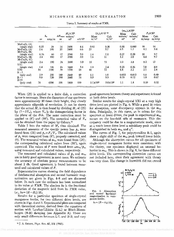
TABLE I. Summary of results at FMR.
M.X104
hw AHrneas webers/ oe amp/m oe m2 ",X 103
MnFe204 (A) (single xtal) 0.35 28 14 2400 4.4
MnFe20. (A) 2.4 190 20 2400 6.6 MnFe204 (B)
(single xtal) 0.76 60 17 2700 5.0 MnFe204 (B) 2.4 190 17 2700 5.0 MnFe20. (C)
(single xtal) 2.4 190 24 2690 5.0 YIG
(single xtal) 1.4 110 16 1660 5.8 YIG 14 1100 59 1530 18 R-l
(poly xtal) 2.9 230 180 2460 69 R-l 9.0 720 190 2440 76 R151
(poly xtal) 78 6200 330 1800 130
When (25) is applied to a finite disk, a correction factor is necessary. Since the diameters of our specimens were approximately 10 times their height, they closely approximate ellipsoids of revolution. It can be shown that the actual Ms is then found by dividing Ms of (25) by (1-3N.,), where No; is the demagnetizing factor in the plane of the disk. The same correction must be applied to (8') and (10'). The numerical value of N., can be obtained from the paper by Osborn.13
Table I lists the values of M s thus obtained. The measured amounts of the specific power loss pw were found from (21) and Pw=Ps/V •. The calculated values of pw were computed from (8'), properly corrected, and (9). The measured values of m2w were found from (24); the corresponding calculated values from (10'), again corrected. The values of F were found from Wm2w/ pw, using measured and calculated values, respectively.
The measured and calculated values of pw and m2w are in fairly good agreement in most cases. We estimate the accuracy of absolute power measurements to be about 2 db. Good agreement is found between measured and calculated values of F.
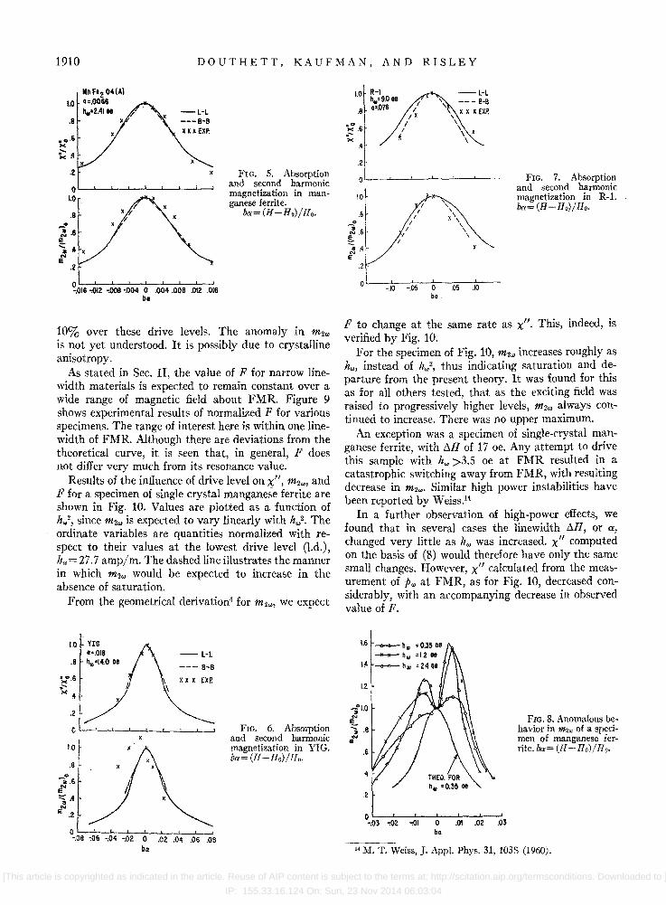
Representative curves showing the field dependence of fundamental absorption and second harmonic magnetization are given in Figs. 4-8 and are discussed below. In each case the ordinate has been normalized to its value at FMR. The abscissa ba is the fractional deviation of the magnetic field from its FMR value, i.e., ba= (H-Ho)/Ho.
Results for a particular specimen of single-crystal manganese ferrite, for two different drive levels, are shown in Figs. 4 and 5. Experimental plots are compared with theoretical curves, derived from the equations of motion with Landau-Lifshitz (L-L) or Bloch-Bloembergen (B-B) damping (see Appendix A). There are only small differences between L-L and B-B, amI very
13 J. A. Osborn, Phys. Rev. 67, 351 (1945).
(m2w)OX 1()4 (Pw)oX 10-10 Meas Calc FoX 106
Meas Calc webers/ webers/ Meas Calc w/m3 w/m3 m2 m2 m/amp m/amp
0.93 0.30 0.18 0.080 10 14 23 9.7 3.5 1.7 8.1 9.4
1.4 1.1 0.27 0.20 10 9.7 7.6 11 1.2 2.0 8.4 9.7
15 15 2.3 3.8 8.2 13
1.9 2.4 0.25 0.36 7.0 8.0 46 72 1.8 3.2 2.1 2.4
1.1 1.0 0.032 0.013 1.6 0.69 9.9 9.5 0.19 0.12 1.0 0.67
3.1X10² 3.0X10² 1.1 1.8 0.19 0.32
good agreement between theory and experiment is found at both drive levels.
Similar results for single-crystal YIG at a very high drive level are plotted in Fig. 6. While a good fit exists for absorption, some discrepancy appears in the m2w data. Principally, in this curve, as in others for this specimen at lower drives, the peak in experimental m2w occurs on the low-field side of resonance. This discrepancy could be due to a magnetostatic mode, since at a much lower drive level a subsidiary peak could be distinguished in both m2w and x".
The curves of Fig. 7, for polycrystalline R-1, again show a slight shift of the m2w peak toward lower fields.
Although the absorption curves for all specimens of single-crystal manganese ferrite were consistent with the theory, one specimen displayed an unusual behavior in m2w. This is shown in Fig. 8, for three different drive levels. The corresponding absorption curves are not included here, since their agreement with theory was very close. The change in linewidth did not exceed
FIG. 4. Absorption and second harmonic magnetization in manganese ferrite.
bu= (H-Ho)/Ho.
Mn Fe204 (AI 1.0 .'.0044
hw'0.35 De
. 8
><°.6
~ .4
.2
.8
.2
~016 -.012 -.008 -.004 0 b.
-l-l --- B-B x x x EXP •
[This article is copyrighted as indicated in the article. Reuse of AIP content is subject to the terms at: http://scitation.aip.org/termsconditions. Downloaded to ]
IP: 155.33.16.124 On: Sun, 23 Nov 2014 06:03:04
1910 DOUTHETT, KAUFMAN, AND RISLEY
lIoFt204(AI 1.0 ".0066
h,,=2.4Ioe .8
-L-L ---8-8
.2
O~~~--~~~--~~~
1.0
. 8
.2
~.016 -.012 -.ooe '.004 0 .004 .OOB .012 .016 bo
FIG. 5. Absorption and second harmoniC magnetization in manganese ferrite.
ba=(H-Ho)/Ho .
!O% over these drive levels. The anomaly in m2., IS ~ot yet understood. It is possibly due to crystalline amsotropy.
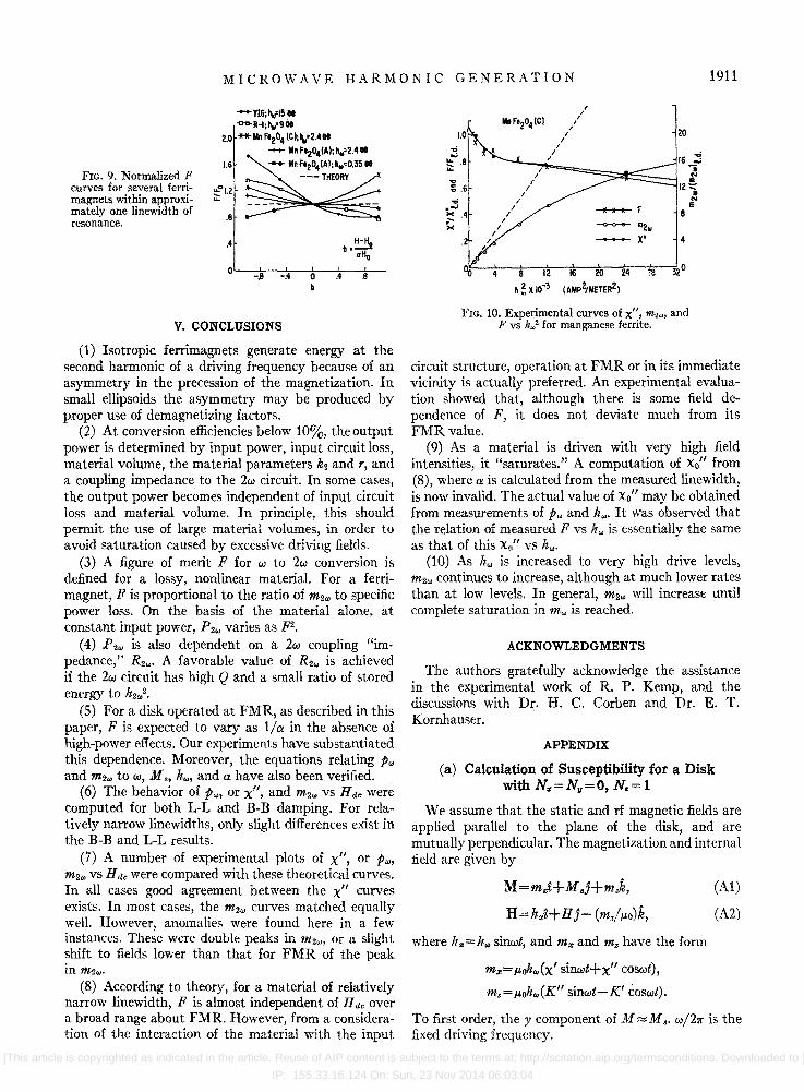
As stated in Sec. II, the value of F for narrow linewidth materials is expected to remain constant over a wide range .of magnetic field about FMR. Figure 9 shows expenmental results of normalized F for various specimens. The range of interest here is within one linewidth of FMR. Although there are deviations from the theoretical curve, it is seen that in general F does
d'ff " not I er very much from its resonance value. Results of the influence of drive level on x" m2 and
Ff . ' "" or a specimen of single crystal manganese ferrite are shown in Fig. 10. Values are plotted as a function of h.,2,. since m2,,: is expected to vary linearly with h.,2, The ordmate vanables are quantities normalized with respect to their values at the lowest drive level (l.d.), hw= 27.7 amp/m. The dashed line illustrates the manner in which m2", would be expected to increase in the absence of saturation.
From the geometrical derivation4 for m2"" we expect
1.0 VIG ·=.OIB
.8 ","=14.008
~.6
~A
.2
1.0
. 8 .
-:.6 e .... '=iA EN
.2
-l-L
--- II-B
~ x x x EXP. \
o~~~~~~~~~ -.08 ~06 -.04 ~02 0 .02 .04 .06 .08
b.
FIG. 6. Absorption and second harmonic magnetization in YIG. ba= (If -llo)/lf" .
1.0 R-I h .. =9.0oe
.8 .-.076
;: .6 .-"" .4
.2
0
I.o!
.8 0
~.6 !.. ~.4 E
.2
-.10
, '\
-.05 0 b •.
-L-l --- B-B X X x EX?
\ \ \
\ x \
.05 .10
FrG. 7. Absorption and second harmonic magnetization in R-1. ba= (H -Ho)/Ho.
F to change at the same rate as x". This, indeed, is verified by Fig. 10.
F?r the specimen of Fig. 10, m2w increases roughly as hOI, mstead of h",2, thus indicating saturation and departure from the present theory. It was found for this as for all others tested, that as the exciting field was raised to progressively higher levels, m2", always continued to increase. There was no upper maximum.
An exception was a specimen of single-crystal manganese ferrite, with !:J.H of 17 oe. Any attempt to drive this sample with h", >3.5 oe at FMR resulted in a catastrophic switching away from FMR, with resulting decrease in m2",. Similar high power instabilities have been reported by W eiss.14
In a furt~er observation of high-power effects, we found that In several cases the linewidth !:J.H or a changed very little as h", was increased. x" co~puted on the basis of (8) would therefore have only the same small changes. However, x" calculated from the meas~rement of fw at FMR, as for Fig. 10, decreased conSiderably, With an accompanying decrease in observed value of F.
1.6
IA
1.2
-itO '" E
::; .8
'" e .6
4
O~-=--7-~--~~--~ -.03 .,02 .,01 0 .01 .02 .03
b.
FIG. 8. Anomalous behavior in m2~ of a specimen of manganese ferrite. ba= (ll - Ho}/lfo.
14 M. T. Weiss, J. AppJ. Phys. 31, 103S (1960).
[This article is copyrighted as indicated in the article. Reuse of AIP content is subject to the terms at: http://scitation.aip.org/termsconditions. Downloaded to ]
IP: 155.33.16.124 On: Sun, 23 Nov 2014 06:03:04
MICROWAVE HARMONIC GENERATION 1911
FIG. 9. Normalized F curves for several ferrimagnets within approximately one linewidth of resonance.
-Y!6;'VIS" <>O-R-l;h.,'9 cit
2.0 ..... Mn F.204 (C);h,,:2.40e
~ MnF·204(Al;h .. '2.4" 1.6 - MnF·204(Al; ..... 0.35"
---THEORY
'::::,°(,2 + ... .8
.4
0~--~B~~-4~-+O--~4~-.~8-b
V. CONCLUSIONS
(1) Isotropic ferrimagnets generate energy at the second harmonic of a driving frequency because of an asymmetry in the precession of the magnetization. In small ellipsoids the asymmetry may be produced by proper use of demagnetizing factors.
(2) At conversion efficiencies below 10%, the output power is determined by input power, input circuit loss, material volume, the material parameters k2 and T, and a coupling impedance to the 2w circuit. In some cases, the output power becomes independent of input circuit loss and material volume. In principle, this should permit the use of large material volumes, in order to avoid saturation caused by excessive driving fields.
(3) A figure of merit F for w to 2w conversion is defined for a lossy, nonlinear material. For a ferrimagnet, F is proportional to the ratio of m2,., to specific power loss. On the basis of the material alone, at constant input power, P2,., varies as F2.
(4) P2,., is also dependent on a 2w coupling "impedance," R2,.,. A favorable value of R2., is achieved if the 2w circuit has high Q and a small ratio of stored energy to 1t2",2.
(5) For a disk operated at FMR, as described in this paper, F is expected to vary as l/a in the absence of high-power effects. Our experiments have substantiated this dependence. Moreover, the equations relating pO! and m2w to w, M 8, h,." and a have also been verified.
(6) The behavior of PIN, or x", and m2w vs Hdc were computed for both L-L and B-B damping. For relatively narrow linewidths, only slight differences exist in the B-B and L-L results.
(7) A number of experimental plots of x", or P"" m2w vs H de were compared with these theoretical curves. In all cases good agreement between the X" curves exists. In most cases, the m2w curves matched equally welL However, anomalies were found here in a few instances. These were double peaks in m2w, or a slight shift to fields lower than that for FMR of the peak inm2",.
(8) According to theory, for a material of relatively narrow linewidth, F is almost independent of H de over a broad range about FMR. However, from a consideration of the interaction of the material with the input
... : .6
-.:! .-~ .4 ><
I I
I
I I
I
, , , , 20
4
4 12 16 20 24 ~ 32°
h ~ X 10-3 (AMPZ/METER2)
FIG. 10. Experimental curves of x", m2", and F vs h,,2 for manganese ferrite.
circuit structure, operation at FMR or in its immediate vicinity is actually preferred. An experimental evaluation showed that, although there is some field dependence of F, it does not deviate much from its FMR value.
(9) As a material is driven with very high field intensities, it "saturates." A computation of XO" from (8), where a is calculated from the measured linewidth, is now invalid. The actual value of Xo" may be obtained from measurements of pw and It",. It was observed that the relation of measured F vs hw is essentially the same as that of this xo" vs hw.
(10) As h", is increased to very high drive levels, m2., continues to increase, although at much lower rates than at low levels. In general, m2w will increase until complete saturation in m .. is reached.
ACKNOWLEDGMENTS
The authors gratefully acknowledge the assistance in the experimental work of R. P. Kemp, and the discussions with Dr. H. C. Corben and Dr. E. T. Kornhauser.
APPENDIX
(a) Calculation of Susceptibility for a Disk with N.,=Ny=O, N.=l
We assume that the static and rf magnetic fields are applied parallel to the plane of the disk, and are mutually perpendicular. The magnetization and internal field are given by
M=mJ+M.J+mzk,
H=h"t+Hj- (mz/p.o)k,
where h",=h .. sinwt, and m,. and m. have the form
m;r;=pOh.,(x' sinwt+x" coswt),
mz=f.loh.,(K" sinwt-K' coswt).
(Al)
(A2)
To first order, the y component of M ~M8' w/27r is the fixed driving frequency.
[This article is copyrighted as indicated in the article. Reuse of AIP content is subject to the terms at: http://scitation.aip.org/termsconditions. Downloaded to ]
IP: 155.33.16.124 On: Sun, 23 Nov 2014 06:03:04

1912 DOUTHETT, KAUFMAN, AND RISLEY
Substituting (Al) and (A2) into (1), and solving for the components of the susceptibility, we get
x'= ('Y2M./J.l.02D)[B('Y2BH/J.l.o-w2) +w2a2(B+J.l.oH)], (A3)
x"= (w-yaM./J.l.oD) [w2+ ('Y2B2/J.l.02)], (A4)
K'= (w'YM./J.l.oD)[('Y2BH/p.o)-w2], (AS)
K"= (w2'Y2aM'/J.l.o2D) (B+J.l.oH) , (A6)
where
D=l'Y2~H - w2r+[w:oa(B+J.l.OH) r
and B=J.l.oH+M •. At FMR the angular frequency is w= ('Y2BoHo/J.l.o)!. The field dependence of x" for several values of a is shown by the curves labeled L-L in Figs. 4-7. In each case x" is normalized to its resonance value (S').
(b) Calculation of 2w Magnetization
In the second-order calculation for m2w, it can be shown that there are no double frequency components in the x or z directions. Therefore, the expressions for M and H given by (A1), (A2) may be rewritten as
M = (x' sinwt+x" coswt)J.l.ohw'i
(c) Determination of Loss Parameter a
To find the value of a from experimental data, we compared the x" /xo" curve with a series of theoretical curves, computed from (A4). We observed from the latter that for the disk, a is not merely the ratio !::.H/Ho, where!::.H is the measured half-linewidth. Instead, a corrected value fJH must be used. The ratio fJH/!::.H is a function of Ms, or the ratio w/'YHo.
From the series of theoretical x" curves,
fJH 1 [ (!::.H) + ]
a= Ho = Ho 0.39(w/'YHo)2+0.S7 ' (A12)
where (!::.H)+=H+-Ho; and H+ is the high-field value of H at which x"/xo"=t.
The values of a used in plotting the theoretical curves labeled L-L of Figs. 4-7 were found from the corresponding experimental curves by this method.
For cases in which an experimental curve is asymmetric, the agreement between theory and experiment in x"/xo" is better on the high-field side of FMR than on the low-field side. This is not surprising since a was derived from H+.
(d) Bloch-Bloembergen Damping for a Disk with N,,=Ny=O, Nz=l
The equation of motion for M with Bloch-Bloembergen damping is + (M.+mI sin2wt+m2 cos2wt)j
+ (K" sinwt-K' coswt)J.l.ohJ?-, (A7) M",z='Y(MXH)",z- (M",z/T2), (A13)
H=hw sinwti+HJ-hw(K" sinwt-K' coswt)k.
Substituting (A7) and (AS) into (1), and neglecting terms of order hw3, the solution for the amplitude of the second harmonic magnetization m2w is
(A9) where
-J.l.O~h}[ mi = K" +x' K" +x" K'
4(BH)!
and J.l.oJhw2
[ m2=--- K'+x'K'-x"K"
4(BHP
+~{ -MsX"-2BK1K"+2J.1.oHX'X"}]' (All) M.
To compare with experiment, m2w is normalized to its value at FMR given by (10'). The curves labeled L-L in Figs. 4-7 show the variation of m2w/ (m2w)O in the vicinity of resonance.
where TI, T2 are the longitudinal and transverse relaxation times, respectively. At low-signal levels, when 'Y2h}TIT2«1, the half-line width within a few percent is given by !::.H meas = 1/ ( I 'Y I T 2)' This is in contrast to the case of L-L damping, where a can differ by as much as 30% from the measured !::.H/Ho. In general, since aHo~I/(I'Y1 T 2), it was of interest to compare the measured values of x" and m2w with the theoretical curves computed with B-B damping.
Equations (A13) and (AI4) are solved as before for x" and m2W, using the expressions for M and H given by (AI) and (A2). At FMR, XB_B" is
I'Y I MsT2(1+M./J.l.oHo)! (XtLB)O- .
2J.1.o (A1S)
The second harmonic magnetization at FMR is found to be
(A16)
Though not given here, the off-resonance expressions for x" and m2w were calculated. These were then normalized by (AtS) and (At6), respectively. The resulting curves labeled B-B are shown in Figs. 4-7. In computing each curve, the appropriate value of T 2,
derived from !::.H meas, was used.
[This article is copyrighted as indicated in the article. Reuse of AIP content is subject to the terms at: http://scitation.aip.org/termsconditions. Downloaded to
] IP: 155.33.16.124 On: Sun, 23 Nov 2014 06:03:04