microstructure and mechanical properties of astm a743 ... · microstructure and mechanical...
TRANSCRIPT
DOI: http://dx.doi.org/10.1590/1980-5373-MR-2017-0468Materials Research. 2017; 20(6): 1622-1629 © 2017
Microstructure and Mechanical Properties of ASTM A743 CA6NM Steel Welded by FCAW Process
Rafael de Paula Silvaa*, Maria Ismenia Sodero Toledo Fariaa, Luiz Fernando Cursino Briet de Almeidaa,
Carlos Angelo Nunesa, Décio Vieiraa, Wanderlei Borges Júniora
Received: May 05, 2017; Accepted: August 09, 2017
CA6NM steel is widely used in the manufacture of hydraulic turbines metallic parts, due to its resistance to corrosion and cavitation damage, combined with good weldability and fatigue properties. However, welding of this type of steel is complex and to ensure a minimum residual stress after welding it is necessary perform a post welding heat treatment (PWHT) of the part. This study aims to analyze the effect of a PWHT on the microstructure and mechanical properties of CA6NM steel weld joint produced by the FCAW process and compare it with the characteristics of an as-welded joint. A martensitic microstructure has been present in both materials. However, the PWHT material has shown finely dispersed retained austenite, in an amount near 10 vol.%. Vickers microhardness values of all regions of PWHT welded joint present lower hardness values compared to those of the as-welded joint. Despite nearly identical toughness values of the weld metal from AW and PWHT samples, results of fracture analysis have shown distinct features in appearance of the fractures.
Keywords: martensitic stainless steel, ASTM A743 CA6NM, FCAW process.
*e-mail: [email protected]
1. Introduction
CA6NM steel (ASTM A743A743M (1998)1) is as soft martensitic stainless steel used in several cast parts of hydraulic turbines. It is the most common metallic alloy used in the manufacture of this type of equipment, replacing -Mn steels by offering better resistance against corrosion and cavitation damage2.
The low-carbon Martensitic steels CA6NM is offset with the addition of nickel, whose purpose is to expand the austenitic field, Therefore, keep the potential and enable complete austenitization and also to temper with the formation of martensite. The mechanical properties and impact strength features of the material are improved1,2.
Welding is extensively used in the assembling and repair of components made of CA6NM steel. Typically, the resulting microstructure at room temperature consists of tempered martensite and it can contain small amounts of δ ferrite and retained austenite3. According to the literature2,4, retained austenite improves mechanical properties such as impact toughness while the presence of delta ferrite may deteriorate the impact properties and raises the ductile to brittle transition temperature5,6.
The reduction of the toughness, as well as the high residual stresses, can shorten the life of the pieceas well as accelerate the cavitation process. However, the completion of heat treatment is limited by manufacturing condition and the size of the structures, the treatment is typically made in large
ovens heated by the combustion of fossil fuels, which carries on air pollution and drastic effects on the environment6,7.
Post weld heat-treatment (PWHT) of this material is applied to ensure a minimum residual stress of the component and increase the toughness. Low toughness reduces the life of the piece and accelerates the process of cavitation as well7.
The objective of this work was to evaluate the possible gains obtained by the application of a stress relieve heat-treatment through evaluation of the microstructure and mechanical properties, specially Charpy V-Notch (CVN) toughness, of CA6NM steel welded joints produced by the Flux Cored Arc Weld (FCAW) process. The work was divided into three main parts: welding (process of preparation of the samples, the consumable and realization of welding), microstructural analysis (optical microscopy, SEM with EDS, macrography and XRD); and analysis of mechanical properties (impact testing, hardness testing).
2. Experimental Procedure
The steel plate used in this work was manufactured by Electro Steel Altona S.A. According to the manufacturer, the material was produced in an electric arc furnace, refined using an AOD furnace (Argon Oxygen Decarburization) and cast in sand molds as blocks of 300x400x45 mm dimensions. The blocks were then submitted to a heat treatment involving quenching and tempering to achieve the required mechanical
aEscola de Engenharia de Lorena, Universidade de São Paulo, Lorena, SP, Brazil
1623Microstructure and Mechanical Properties of ASTM A743 CA6NM Steel Welded by FCAW Process
properties. Table 1 presents the CA6NM chemical composition provided by the manufacturer which is in agreement with the ASTM standard1.
Table 1. CA6NM steel chemical composition (wt.%) according to ASTM vs. Chemical analysis provided by the manufacturer10.
Element Manufacturer (ALTONA)
ASTM A 743/A 743M (1998)
Carbon 0.02 0.06 max.
Manganese 0.77 1.00 max.
Silícon 0.47 1.00 max.
Chrome 12.08 11.5 – 14
Níckel 3.80 3.5 – 4.5
Molybdenum 0.46 0.4 – 1.0
Phosphor 0.04 0.04 max.
Sulfur 0.01 0.03 max.
Aluminum 0.01 ----------
The welding consumable was flux cored AWS E410NiMoT1-4-1 of 1.6 mm diameter which meets the ASME and AWS standard and specification 9 SFA 5.22. Table 2 presents the chemical composition of the weld metal.
Table 2. Specified chemical composition of the welding consumable from AWS E410NiMoT1-4-1 electrode.
Element Deposited weld metal Specified
Carbon 0.025 0.06
Manganese 0.36 1.0
Silícon 0.36 1.0
Chrome 11.99 11.0 – 12.5
Níckel 4.42 4.0 – 5.0
Molybdenum 0.50 0.40 – 0.70
Phosphor 0.009 0.04
Copper 0.03 0.75
Sulfur 0.010 0.03
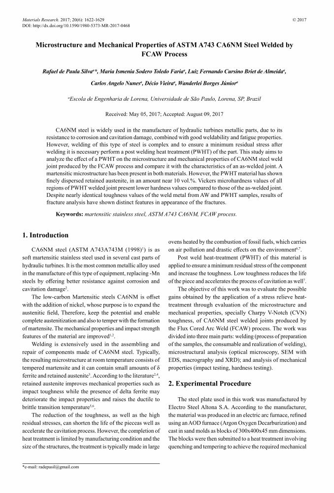
The plate was cut into four strips of 97x300x45 (mm) which were then machined to make chamfers for X shaped welds, as shown in Figure 1. The welding process was the FCAW, using a multi-threaded electronic welding machine LINCOLN model POWERTEC 305 c PRO and torch to pre and post-heat. The shielding gas used was SG-AC-25, 75% Argon- 25%CO2.
The chamfered strips were pre heated to 100°C before welding to decrease the cooling rate of the welding joint, seeking to avoid the formation of harmful microstructures in the weld, which may cause cold cracks as well as to mitigate the generation of residual stresses. A ceramic backing was added on the opposite side of the joint to provide a high
Figure 1. Illustration of the size of the specimens prepared for welding.
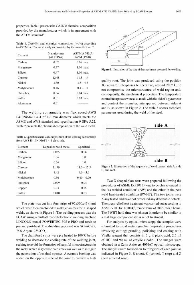
quality root. The joint was produced using the position 3G upward, interpasses temperature, around 200° C, to not compromise the microstructure of weld region and, consequently, the mechanical properties. The temperature control interpasses were also made with the aid of a pyrometer and contact thermometer. interspersed between sides A and B, as shown in Figure 2. The table 3 shows technical parameters used during the weld of the steel.
Figure 2. Illustration of the sequence of weld passes, side A, side B, and root.
Two X shaped plate tests were prepared following the procedures of ASME IX (2013)8 one to be characterized in the "as-welded condition" (AW) and the other in the post weld heat-treated condition (PWHT). The two joints were X-ray tested and have not presented any detectable defects. The stress relief heat treatment was carried out according to ASME VIII Div. I (2004)9, temperature of 580° C for 8 hours. The PWHT hold time was chosen in order to be similar to a real large component stress relief treatment.
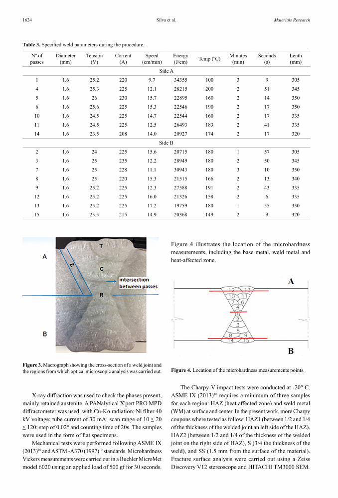
For analysis by optical microscopy, the samples were submitted to usual metallographic preparation procedures involving cutting; grinding, polishing and etching with Vilella reagent that consists in 5 g if picric acid, 2.5 ml of HCl and 90 ml of ethylic alcohol. The images were obtained in a Zeiss Axiovert 40MAT optical microscope. The analysis were focused on four regions of each joint as indicated in Figure 3, R (root), C (center), T (top) and Z (heat affected zone).
Silva et al.1624 Materials Research
Table 3. Specified weld parameters during the procedure.
Nº of passes
Diameter (mm)
Tension (V)
Corrent (A)
Speed (cm/min)
Energy (J/cm) Temp (ºC) Minutes
(min)Seconds
(s)Lenth (mm)
Side A
1 1.6 25.2 220 9.7 34355 100 3 9 305
4 1.6 25.3 225 12.1 28215 200 2 51 345
5 1.6 26 230 15.7 22895 160 2 14 350
6 1.6 25.6 225 15.3 22546 190 2 17 350
10 1.6 24.5 225 14.7 22544 160 2 17 335
11 1.6 24.5 225 12.5 26493 183 2 41 335
14 1.6 23.5 208 14.0 20927 174 2 17 320
Side B
2 1.6 24 225 15.6 20715 180 1 57 305
3 1.6 25 235 12.2 28949 180 2 50 345
7 1.6 25 228 11.1 30943 180 3 10 350
8 1.6 25 220 15.3 21515 166 2 13 340
9 1.6 25.2 225 12.3 27588 191 2 43 335
12 1.6 25.2 225 16.0 21326 158 2 6 335
13 1.6 25.2 225 17.2 19759 180 1 55 330
15 1.6 23.5 215 14.9 20368 149 2 9 320
Figure 3. Macrograph showing the cross-section of a weld joint and the regions from which optical microscopic analysis was carried out.
X-ray diffraction was used to check the phases present, mainly retained austenite. A PANalytical X'pert PRO MPD diffractometer was used, with Cu-Kα radiation; Ni filter 40 kV voltage; tube current of 30 mA; scan range of 10 ≤ 2θ ≤ 120; step of 0.02° and counting time of 20s. The samples were used in the form of flat specimens.
Mechanical tests were performed following ASME IX (2013)10 and ASTM -A370 (1997)10 standards. Microhardness Vickers measurements were carried out in a Buehler MicroMet model 6020 using an applied load of 500 gf for 30 seconds.
Figure 4. Location of the microhardness measurements points.
Figure 4 illustrates the location of the microhardness measurements, including the base metal, weld metal and heat-affected zone.
The Charpy-V impact tests were conducted at -20° C. ASME IX (2013)10 requires a minimum of three samples for each region: HAZ (heat affected zone) and weld metal (WM) at surface and center. In the present work, more Charpy coupons where tested as follow: HAZ1 (between 1/2 and 1/4 of the thickness of the welded joint an left side of the HAZ), HAZ2 (between 1/2 and 1/4 of the thickness of the welded joint on the right side of HAZ), S (3/4 the thickness of the weld), and SS (1.5 mm from the surface of the material). Fracture surface analysis were carried out using a Zeiss Discovery V12 stereoscope and HITACHI TM3000 SEM.
1625Microstructure and Mechanical Properties of ASTM A743 CA6NM Steel Welded by FCAW Process
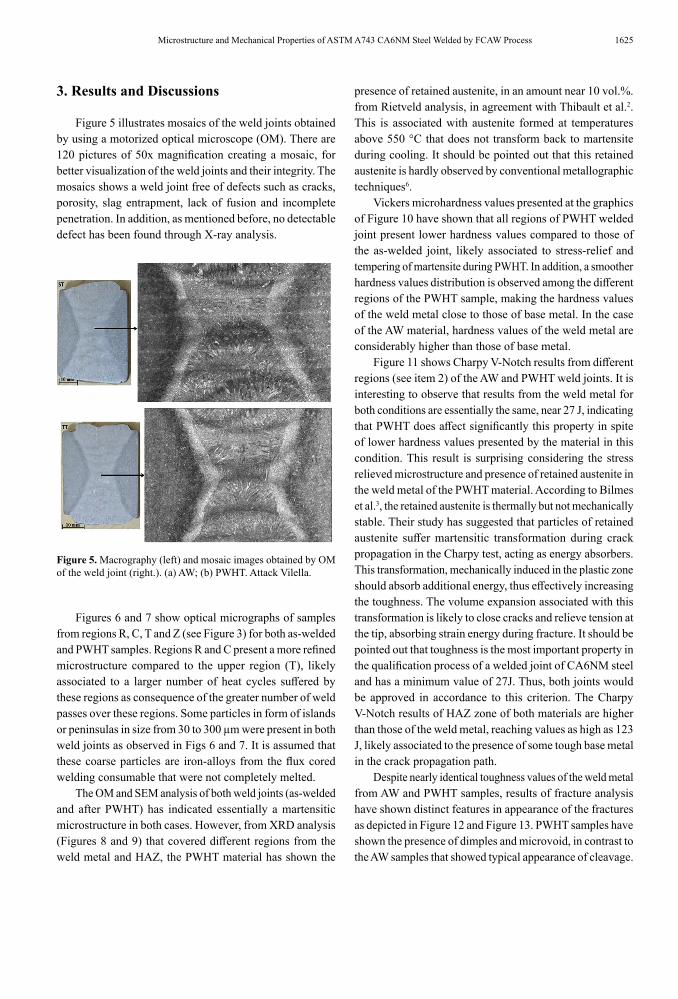
Figure 5. Macrography (left) and mosaic images obtained by OM of the weld joint (right.). (a) AW; (b) PWHT. Attack Vilella.
3. Results and Discussions
Figure 5 illustrates mosaics of the weld joints obtained by using a motorized optical microscope (OM). There are 120 pictures of 50x magnification creating a mosaic, for better visualization of the weld joints and their integrity. The mosaics shows a weld joint free of defects such as cracks, porosity, slag entrapment, lack of fusion and incomplete penetration. In addition, as mentioned before, no detectable defect has been found through X-ray analysis.
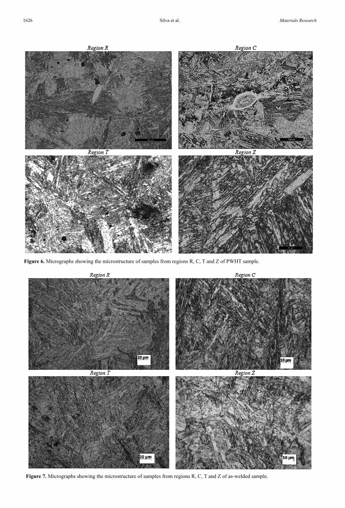
Figures 6 and 7 show optical micrographs of samples from regions R, C, T and Z (see Figure 3) for both as-welded and PWHT samples. Regions R and C present a more refined microstructure compared to the upper region (T), likely associated to a larger number of heat cycles suffered by these regions as consequence of the greater number of weld passes over these regions. Some particles in form of islands or peninsulas in size from 30 to 300 µm were present in both weld joints as observed in Figs 6 and 7. It is assumed that these coarse particles are iron-alloys from the flux cored welding consumable that were not completely melted.
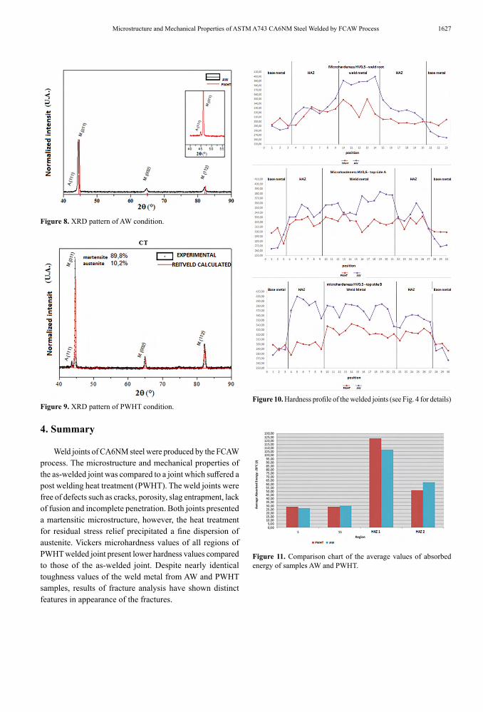
The OM and SEM analysis of both weld joints (as-welded and after PWHT) has indicated essentially a martensitic microstructure in both cases. However, from XRD analysis (Figures 8 and 9) that covered different regions from the weld metal and HAZ, the PWHT material has shown the
presence of retained austenite, in an amount near 10 vol.%. from Rietveld analysis, in agreement with Thibault et al.2. This is associated with austenite formed at temperatures above 550 °C that does not transform back to martensite during cooling. It should be pointed out that this retained austenite is hardly observed by conventional metallographic techniques6.
Vickers microhardness values presented at the graphics of Figure 10 have shown that all regions of PWHT welded joint present lower hardness values compared to those of the as-welded joint, likely associated to stress-relief and tempering of martensite during PWHT. In addition, a smoother hardness values distribution is observed among the different regions of the PWHT sample, making the hardness values of the weld metal close to those of base metal. In the case of the AW material, hardness values of the weld metal are considerably higher than those of base metal.
Figure 11 shows Charpy V-Notch results from different regions (see item 2) of the AW and PWHT weld joints. It is interesting to observe that results from the weld metal for both conditions are essentially the same, near 27 J, indicating that PWHT does affect significantly this property in spite of lower hardness values presented by the material in this condition. This result is surprising considering the stress relieved microstructure and presence of retained austenite in the weld metal of the PWHT material. According to Bilmes et al.3, the retained austenite is thermally but not mechanically stable. Their study has suggested that particles of retained austenite suffer martensitic transformation during crack propagation in the Charpy test, acting as energy absorbers. This transformation, mechanically induced in the plastic zone should absorb additional energy, thus effectively increasing the toughness. The volume expansion associated with this transformation is likely to close cracks and relieve tension at the tip, absorbing strain energy during fracture. It should be pointed out that toughness is the most important property in the qualification process of a welded joint of CA6NM steel and has a minimum value of 27J. Thus, both joints would be approved in accordance to this criterion. The Charpy V-Notch results of HAZ zone of both materials are higher than those of the weld metal, reaching values as high as 123 J, likely associated to the presence of some tough base metal in the crack propagation path.
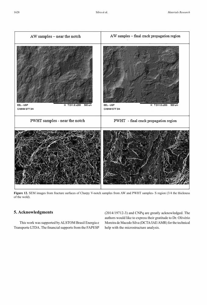
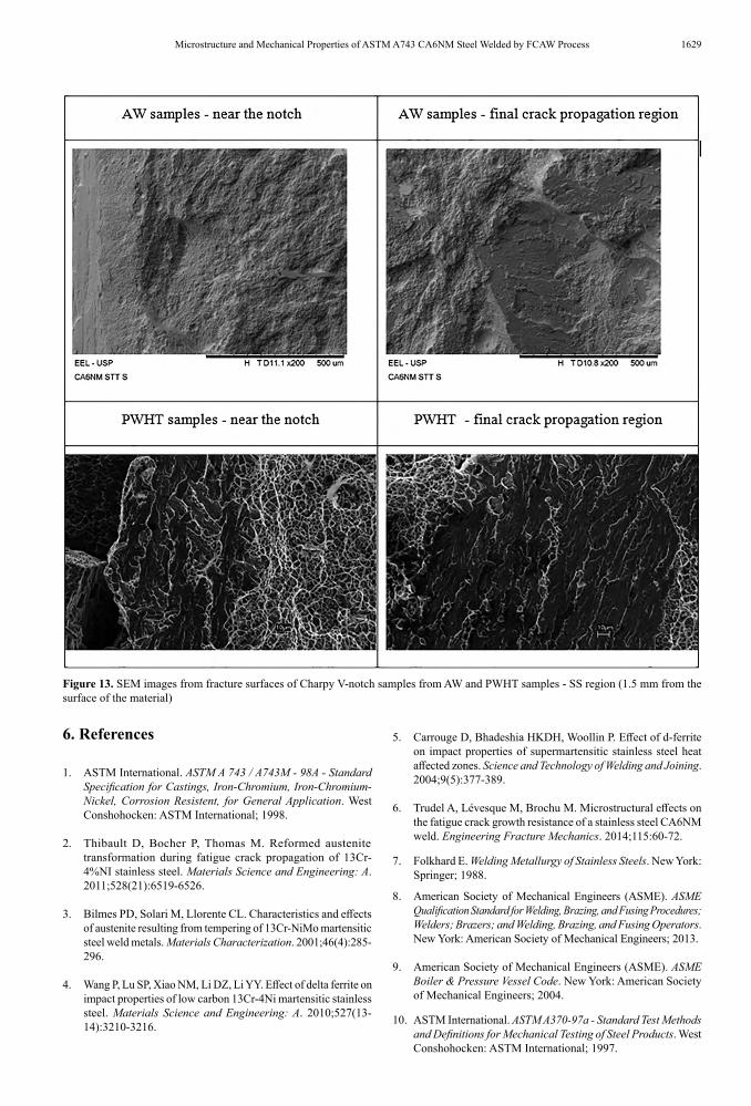
Despite nearly identical toughness values of the weld metal from AW and PWHT samples, results of fracture analysis have shown distinct features in appearance of the fractures as depicted in Figure 12 and Figure 13. PWHT samples have shown the presence of dimples and microvoid, in contrast to the AW samples that showed typical appearance of cleavage.
Silva et al.1626 Materials Research
Figure 6. Micrographs showing the microstructure of samples from regions R, C, T and Z of PWHT sample.
Figure 7. Micrographs showing the microstructure of samples from regions R, C, T and Z of as-welded sample.
1627Microstructure and Mechanical Properties of ASTM A743 CA6NM Steel Welded by FCAW Process
Figure 8. XRD pattern of AW condition.
Figure 9. XRD pattern of PWHT condition.Figure 10. Hardness profile of the welded joints (see Fig. 4 for details)
Figure 11. Comparison chart of the average values of absorbed energy of samples AW and PWHT.
4. Summary
Weld joints of CA6NM steel were produced by the FCAW process. The microstructure and mechanical properties of the as-welded joint was compared to a joint which suffered a post welding heat treatment (PWHT). The weld joints were free of defects such as cracks, porosity, slag entrapment, lack of fusion and incomplete penetration. Both joints presented a martensitic microstructure, however, the heat treatment for residual stress relief precipitated a fine dispersion of austenite. Vickers microhardness values of all regions of PWHT welded joint present lower hardness values compared to those of the as-welded joint. Despite nearly identical toughness values of the weld metal from AW and PWHT samples, results of fracture analysis have shown distinct features in appearance of the fractures.
Silva et al.1628 Materials Research
Figure 12. SEM images from fracture surfaces of Charpy V-notch samples from AW and PWHT samples- S region (3/4 the thickness of the weld).
5. Acknowledgments
This work was supported by ALSTOM Brasil Energia e Transporte LTDA. The financial supports from the FAPESP
(2014/19712-3) and CNPq are greatly acknowledged. The authors would like to express their gratitude to Dr. Olivério Moreira de Macedo Silva (DCTA/IAE/AMR) for the technical help with the microstructure analysis.
1629Microstructure and Mechanical Properties of ASTM A743 CA6NM Steel Welded by FCAW Process
Figure 13. SEM images from fracture surfaces of Charpy V-notch samples from AW and PWHT samples - SS region (1.5 mm from the surface of the material)
6. References
1. ASTM International. ASTM A 743 / A743M - 98A - Standard Specification for Castings, Iron-Chromium, Iron-Chromium-Nickel, Corrosion Resistent, for General Application. West Conshohocken: ASTM International; 1998.
2. Thibault D, Bocher P, Thomas M. Reformed austenite transformation during fatigue crack propagation of 13Cr-4%NI stainless steel. Materials Science and Engineering: A. 2011;528(21):6519-6526.
3. Bilmes PD, Solari M, Llorente CL. Characteristics and effects of austenite resulting from tempering of 13Cr-NiMo martensitic steel weld metals. Materials Characterization. 2001;46(4):285-296.
4. Wang P, Lu SP, Xiao NM, Li DZ, Li YY. Effect of delta ferrite on impact properties of low carbon 13Cr-4Ni martensitic stainless steel. Materials Science and Engineering: A. 2010;527(13-14):3210-3216.
5. Carrouge D, Bhadeshia HKDH, Woollin P. Effect of d-ferrite on impact properties of supermartensitic stainless steel heat affected zones. Science and Technology of Welding and Joining. 2004;9(5):377-389.
6. Trudel A, Lévesque M, Brochu M. Microstructural effects on the fatigue crack growth resistance of a stainless steel CA6NM weld. Engineering Fracture Mechanics. 2014;115:60-72.
7. Folkhard E. Welding Metallurgy of Stainless Steels. New York: Springer; 1988.
8. American Society of Mechanical Engineers (ASME). ASME Qualification Standard for Welding, Brazing, and Fusing Procedures; Welders; Brazers; and Welding, Brazing, and Fusing Operators. New York: American Society of Mechanical Engineers; 2013.
9. American Society of Mechanical Engineers (ASME). ASME Boiler & Pressure Vessel Code. New York: American Society of Mechanical Engineers; 2004.
10. ASTM International. ASTM A370-97a - Standard Test Methods and Definitions for Mechanical Testing of Steel Products. West Conshohocken: ASTM International; 1997.