microsonic_ucs-15_cdd_qm.pdf
TRANSCRIPT

7/27/2019 microsonic_ucs-15_CDD_QM.pdf
http://slidepdf.com/reader/full/microsonicucs-15cddqmpdf 1/8
Extract from our online catalogue:
ucs-15/CDD/QMCurrent to: 2014-06-04
microsonic gmbh, hauert 16, d-44227 dortmund, telephone: +49 231 975151-0, fax: +49 231 975151-51, e-mail: [email protected]
microsonic® is a registered trademark of microsonic GmbH. All rights reserved.

7/27/2019 microsonic_ucs-15_CDD_QM.pdf
http://slidepdf.com/reader/full/microsonicucs-15cddqmpdf 2/8
HighlightsRobust metal housing : : :Robust metal housing : : :Robust metal housing : : :Robust metal housing : : : for harsh usage conditions
D o ve t a i l d e s ign : : :D o ve t a i l d e s ign : : :D o ve t a i l d e s ign : : :D o ve t a i l d e s ign : : : for fast installation
Me c ha n ic a l ly c o m p a t ib le wit h t he in d us t ry s t a n d a rd : : :Me c ha n ic a l ly c o m p a t ib le wit h t he in d us t ry s t a n d a rd : : :Me c ha n ic a l ly c o m p a t ib le wit h t he in d us t ry s t a n d a rd : : :Me c ha n ic a l ly c o m p a t ib le wit h t he in d us t ry s t a n d a rd : : : a true alternative to the optical sensor
Automatic synchronisation : : :Automatic synchronisation : : :Automatic synchronisation : : :Automatic synchronisation : : : for simultaneous operation of up to ten sensors in close quarters
2 a n t i2 a n t i2 a n t i2 a nt i----valent switching outputs in pnp or npn variantvalent switching outputs in pnp or npn variantvalent switching outputs in pnp or npn variantvalent switching outputs in pnp or npn variant
m ic ro s o n ic T e a c hm ic ro s o n ic T e a c hm ic ro s o n ic T e a c hm ic ro s o n ic T e a c h----i n us ing a bu tto nin using a buttonin using a buttonin using a button
0.1 mm resolution0.1 mm resolution0.1 mm resolution0.1 mm resolution
Temperature compensationTemperature compensationTemperature compensationTemperature compensation
101 01010––––3 0 V op er at in g v ol ta ge30 V o p e ra t in g vo lt a ge30 V o p e ra t in g vo lt a ge30 V o p e ra t in g vo lt a ge
LinkControl : : :LinkControl : : :LinkControl : : :LinkControl : : : for configuration of sensors from a PC
Basics
The ucs sensors in a
sturdy metal housing are
mechanically compatible
with the industrial
standard of opto
sensors.
::: ucs ultrasonic sensors :::
7/27/2019 microsonic_ucs-15_CDD_QM.pdf
http://slidepdf.com/reader/full/microsonicucs-15cddqmpdf 3/8
Description
The sturdy metal housingThe sturdy metal housingThe sturdy metal housingThe sturdy metal housing
of the ucs sensors is mechanically compatible with the industrial standard of optical sensors.
The rotatable circular connectorThe rotatable circular connectorThe rotatable circular connectorThe rotatable circular connector
allows for flexible selection of the mounting location and facilitates flexible wiring.
The ucs sensorsThe ucs sensorsThe ucs sensorsThe ucs senso r s
With the anti-valent switching behaviour of the two switching outputs, the first output works as an NO contact and the
second works complementarily as an NC contact.
The TeachThe TeachThe TeachThe Teach----i n bu tt onin buttonin buttonin button
on the sensor´s top allows for a convenient setting of the desired detection distance and operating mode.
A dual LEDA dual LEDA dual LEDA dual LED
indicates the switching status of the two anti-valent switching outputs.
The ucs sensors have three operating modes:The ucs sensors have three operating modes:The ucs sensors have three operating modes:The ucs sensors have three operating modes:
Single switching point
Two-way reflective barrier
Window mode
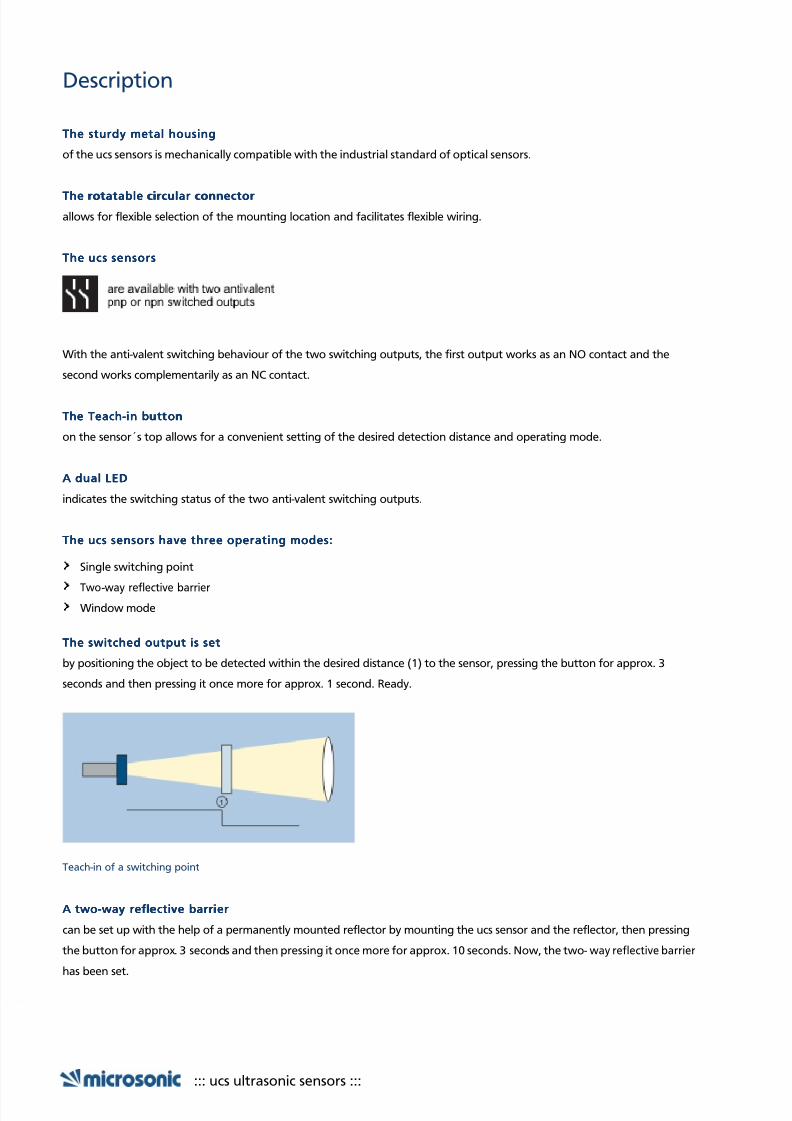
The switched output is setThe switched output is setThe switched output is setThe switched output is set
by positioning the object to be detected within the desired distance (1) to the sensor, pressing the button for approx. 3
seconds and then pressing it once more for approx. 1 second. Ready.
Teach-in of a switching point
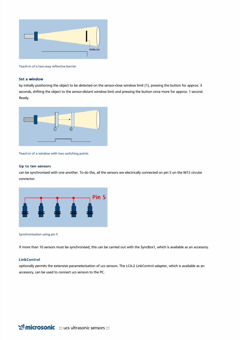
A twoA twoA twoA two----way refle ctiv e barri erway reflective barrierway reflective barrierway reflective barrier
can be set up with the help of a permanently mounted reflector by mounting the ucs sensor and the reflector, then pressing
the button for approx. 3 seconds and then pressing it once more for approx. 10 seconds. Now, the two-way reflective barrier
has been set.
::: ucs ultrasonic sensors :::
7/27/2019 microsonic_ucs-15_CDD_QM.pdf
http://slidepdf.com/reader/full/microsonicucs-15cddqmpdf 4/8
Teach-in of a two-way reflective barrier
Set a windowSet a windowSet a windowSet a window
by initially positioning the object to be detected on the sensor-close window limit (1), pressing the button for approx. 3
seconds, shifting the object to the sensor-distant window limit and pressing the button once more for approx. 1 second.
Ready.
Teach-in of a window with two switching points
Up to ten sensorsUp to ten sensorsUp to ten sensorsUp to ten sensors
can be synchronised with one another. To do this, all the sensors are electrically connected on pin 5 on the M12 circular
connector.
Synchronisation using pin 5
If more than 10 sensors must be synchronised, this can be carried out with the SyncBox1, which is available as an accessory.
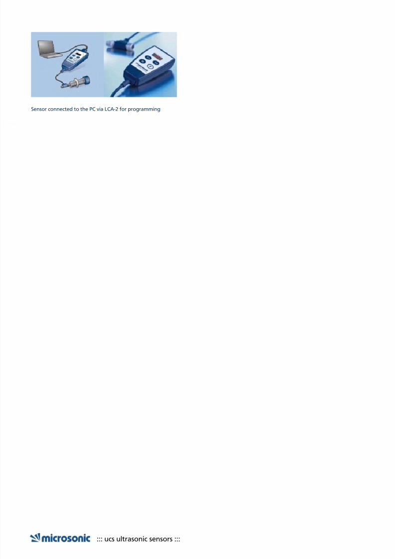
LinkControlLinkControlLinkControlLinkControl
optionally permits the extensive parameterisation of ucs sensors. The LCA-2 LinkControl adapter, which is available as an
accessory, can be used to connect ucs sensors to the PC.
::: ucs ultrasonic sensors :::
7/27/2019 microsonic_ucs-15_CDD_QM.pdf
http://slidepdf.com/reader/full/microsonicucs-15cddqmpdf 5/8
Sensor connected to the PC via LCA-2 for programming
::: ucs ultrasonic sensors :::

7/27/2019 microsonic_ucs-15_CDD_QM.pdf
http://slidepdf.com/reader/full/microsonicucs-15cddqmpdf 6/8
7/27/2019 microsonic_ucs-15_CDD_QM.pdf
http://slidepdf.com/reader/full/microsonicucs-15cddqmpdf 7/8
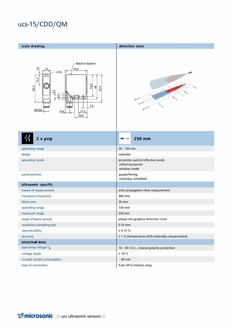
scale drawingscale drawingscale drawingscale drawing detection zonedetection zonedetection zonedetection zone
2 x pnp2 x pnp2 x pnp2 x pnp 250 mm250 mm250 mm250 mm
operating range 20 - 150 mm
design cuboidal
operating mode proximity switch/reflective mode
reflective barrier
window mode
particularities quaderförmig
schlankes Schallfeld
ultrasonicultrasonicultrasonicul tr ason ic ---- specif icspecif icspecif icspecif ic
means of measurement echo propagation time measurement
transducer frequency 380 kHz
blind zone 20 mm
operating range 150 mm
maximum range 250 mm
angle of beam spread please see graphics detection zone
resolution/sampling rate 0.10 mm
reproducibility ± 0.15 %
accuracy ± 1 % (temperature drift internally compensated)
e lectr ica l dataelectr ical dataelectr ical datae lectr ica l data
operating voltage UB 10 - 30 V d.c., reverse polarity protection
voltage ripple ± 10 %
no-load current consumption 40 mA
type of connection 5-pin M12 initiator plug
::: ucs ultrasonic sensors :::
ucs-15/CDD/QM

7/27/2019 microsonic_ucs-15_CDD_QM.pdf
http://slidepdf.com/reader/full/microsonicucs-15cddqmpdf 8/8
outputsoutputsoutputsoutputs
output 1 switching output
pnp: Imax = 500 mA (U B-2V)NOC/NCC adjustable, short-circuit -proof
output 2 switching outputpnp: Imax = 500 mA (U B-2V)
NOC/NCC adjustable, short-circuit -proof
switching hysteresis 2.0 mm
switching frequency 25 Hz
response time 24 ms
delay prior to availability < 300 ms
inputsinputsinputsinputs
input 1 com input
housinghousinghousinghousing
material zinc die-casting, plastic parts, PBT
ultrasonic transducer polyurethane foam, epoxy resin with glass contents
class of protection to EN 60529 IP 67
operating temperature -25°C to +70°C
storage temperature -40°C to +85°C
weight 75 g
techn ical fe atur es/ cha racteri st ics techn ical fe atur es /chara ct er ist ics tec hni cal fe ature s/cha racteri st ics techn ica l fe atur es/ ch aracter i st ics
temperature compensation yes
controls 1 Taster
Com -Eingangscope for settings Teach-in via push- button
LCA-2 with LinkControl
synchronization yes
multiplex no
indicators 1 x Duo-LED; green: working / yellow: switch status
particularities quaderförmig
schlankes Schallfeld
documentation (download)documentation (download)documentation (download)documentation (download)
pin assignment
::: ucs ultrasonic sensors :::
ucs-15/CDD/QM