microsoft powerpoint - 03 oeb104710 enodeb lte v100r006 field maintance issue 1
TRANSCRIPT

8/13/2019 Microsoft PowerPoint - 03 OEB104710 eNodeB LTE V100R006 Field Maintance ISSUE 1
http://slidepdf.com/reader/full/microsoft-powerpoint-03-oeb104710-enodeb-lte-v100r006-field-maintance-issue 1/63
eNodeB LTE V100R006 Field
Maintenance
www.huawei.com
Copyright © 2013 Huawei Technologies Co., Ltd. All rights reserved.
eNodeB V100R006 FieldMaintenance
Copyright © 2013 Huawei Technologies Co., Ltd. All rights reserved. Page1
Objectives Upon completion of this course, you will be able to:
Know the Local maintenance system
Grasp the procedure of Power on and Power off eNodeB
Grasp replacing of eNodeB components
Know the routine maintenance items of eNodeB

8/13/2019 Microsoft PowerPoint - 03 OEB104710 eNodeB LTE V100R006 Field Maintance ISSUE 1
http://slidepdf.com/reader/full/microsoft-powerpoint-03-oeb104710-enodeb-lte-v100r006-field-maintance-issue 2/63
eNodeB LTE V100R006 Field
Maintenance
Copyright © 2013 Huawei Technologies Co., Ltd. All rights reserved. Page2
Contents
1. Local Operation and Maintenance Introduction
2. Power on and Power off Procedure of eNodeB
3. Replacing Components of eNodeB
4. Maintenance items for eNodeB
Copyright © 2013 Huawei Technologies Co., Ltd. All rights reserved. Page3
Operation and Maintenance SystemStructure
M2000 Server eNodeB
LMT
M2000
Client
Local Maintenance
Remote Maintenance
8/13/2019 Microsoft PowerPoint - 03 OEB104710 eNodeB LTE V100R006 Field Maintance ISSUE 1
http://slidepdf.com/reader/full/microsoft-powerpoint-03-oeb104710-enodeb-lte-v100r006-field-maintance-issue 3/63
eNodeB LTE V100R006 Field
Maintenance
Copyright © 2013 Huawei Technologies Co., Ltd. All rights reserved.
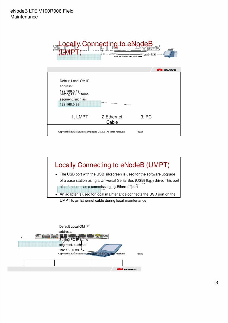
Locally Connecting to eNodeB(LMPT)
Page4
1. LMPT 2.EthernetCable
3. PC
Default Local OM IP
address:
192.168.0.49Setting PC IP same
segment, such as:
192.168.0.88
Copyright © 2013 Huawei Technologies Co., Ltd. All rights reserved.
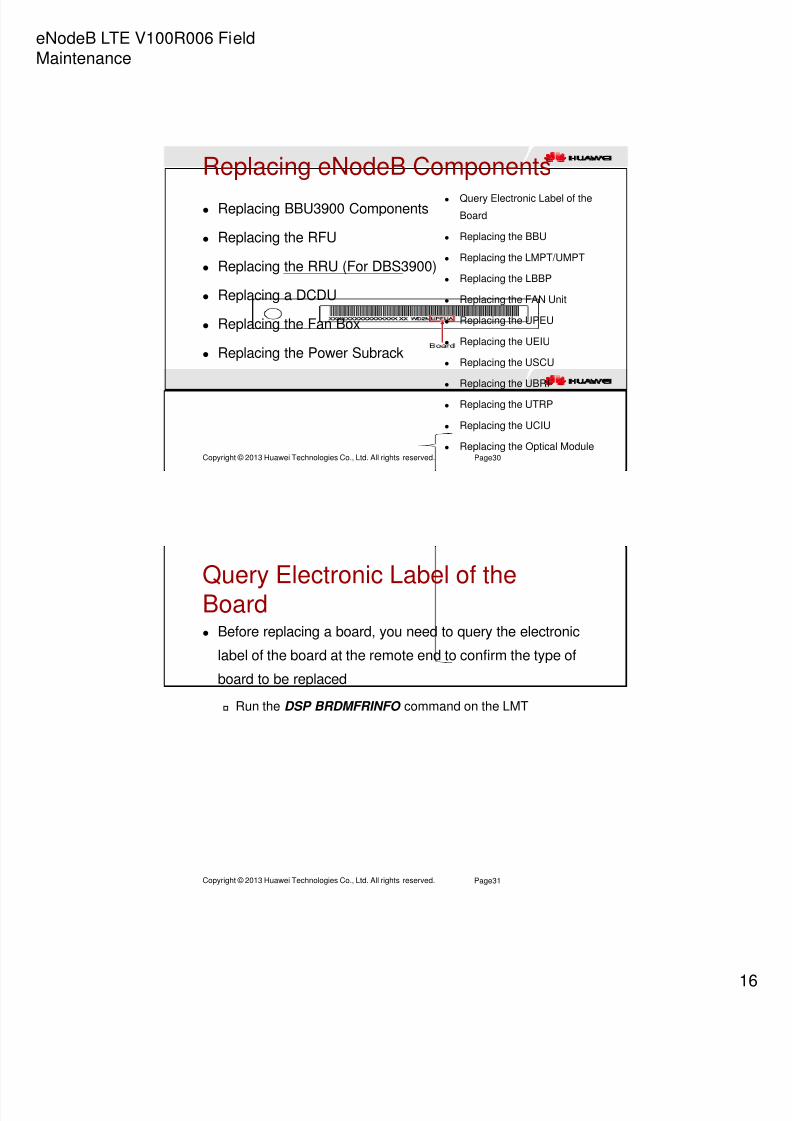
Locally Connecting to eNodeB (UMPT)
The USB port with the USB silkscreen is used for the software upgrade
of a base station using a Universal Serial Bus (USB) flash drive. This port
also functions as a commissioning Ethernet port
An adapter is used for local maintenance connects the USB port on the
UMPT to an Ethernet cable during local maintenance
Page5
Default Local OM IPaddress:
192.168.0.49Setting PC IP same
segment, such as:
192.168.0.88

8/13/2019 Microsoft PowerPoint - 03 OEB104710 eNodeB LTE V100R006 Field Maintance ISSUE 1
http://slidepdf.com/reader/full/microsoft-powerpoint-03-oeb104710-enodeb-lte-v100r006-field-maintance-issue 4/63
eNodeB LTE V100R006 Field
Maintenance
Copyright © 2013 Huawei Technologies Co., Ltd. All rights reserved. Page6
Locally Logging to eNodeB
Local OM IP address:192.168.0.49
User name: admin
Default password: hwbs@com
Copyright © 2013 Huawei Technologies Co., Ltd. All rights reserved.
WebLMT Panel Overview
Page7
Statusbar
Others
Menu bar
Functions

8/13/2019 Microsoft PowerPoint - 03 OEB104710 eNodeB LTE V100R006 Field Maintance ISSUE 1
http://slidepdf.com/reader/full/microsoft-powerpoint-03-oeb104710-enodeb-lte-v100r006-field-maintance-issue 5/63
eNodeB LTE V100R006 Field
Maintenance
Copyright © 2013 Huawei Technologies Co., Ltd. All rights reserved. Page8
MML Commands Introduction
MML command structure : Action + Object
Main action: ADD/MOD/RMV/SET/DSP/LST/SWP/BLK/UBL
Main objective: BRD/RRU/CELL/SCTPLNK/IPPATH
Example:
DSP BRD
BLK BRD
UBL BRD
Black: optional
Red: compulsory
Copyright © 2013 Huawei Technologies Co., Ltd. All rights reserved. Page9
Contents1. Local Operation and Maintenance Introduction
2. Power on and Power off Procedure of eNodeB
3. Replacing Components of eNodeB
4. Maintenance items for eNodeB

8/13/2019 Microsoft PowerPoint - 03 OEB104710 eNodeB LTE V100R006 Field Maintance ISSUE 1
http://slidepdf.com/reader/full/microsoft-powerpoint-03-oeb104710-enodeb-lte-v100r006-field-maintance-issue 6/63
eNodeB LTE V100R006 Field
Maintenance
Copyright © 2013 Huawei Technologies Co., Ltd. All rights reserved.
Prerequisite of Power on BTS3900
Page10
The input power cables are correctly and securely connected.
The power supply to the BTS3900 meets the specifications
listed in Power Supply Requirements of the BTS3900
The Power switches on the DCDU panel are all set to OFF
BTS3900 (Ver.B) has DCDU-01
BTS3900 (Ver.C) has DCDU-11A
BTS3900(Ver.C) has DCDU-12A
The external power supply to the BTS3900 is shut down
Copyright © 2013 Huawei Technologies Co., Ltd. All rights reserved.
Procedure of Power on BTS3900 Step 1 Use a multimeter to measure the resistance
between the external power supply and the ground to
ensure that there is no short circuit.
Step 2 Turn on the external power switch to power on the
BTS3900.
Step 3 Set the circuit breakers on the EPU or EPS for the
corresponding components to ON, and check the powersupply status of each component.
Page11

8/13/2019 Microsoft PowerPoint - 03 OEB104710 eNodeB LTE V100R006 Field Maintance ISSUE 1
http://slidepdf.com/reader/full/microsoft-powerpoint-03-oeb104710-enodeb-lte-v100r006-field-maintance-issue 7/63
eNodeB LTE V100R006 Field
Maintenance
Copyright © 2013 Huawei Technologies Co., Ltd. All rights reserved.
Procedure of Power on BTS3900
Step 4 (Optional) Set the circuit breakers for the
corresponding components on each DCDU in a BTS3900
cabinet to ON. Skip this step if there is no circuit breaker on
the DCDU, such as the DCDU-12A.
Step 5 Set the circuit breaker on the UPEU in the BBU to
ON.
Step 6 Check the power supply to each component
according to the indicator state.
Page12
Copyright © 2013 Huawei Technologies Co., Ltd. All rights reserved.
Procedure of Power on BTS3900 Step 7 (Optional) If the power supply to a component fails
after the cabinet is powered on, handle the fault according
to the instructions in the following table.
Page13

8/13/2019 Microsoft PowerPoint - 03 OEB104710 eNodeB LTE V100R006 Field Maintance ISSUE 1
http://slidepdf.com/reader/full/microsoft-powerpoint-03-oeb104710-enodeb-lte-v100r006-field-maintance-issue 8/63
eNodeB LTE V100R006 Field
Maintenance
Copyright © 2013 Huawei Technologies Co., Ltd. All rights reserved.
Procedure of Power on BTS3900
Page14
Copyright © 2013 Huawei Technologies Co., Ltd. All rights reserved.
Procedure of Power on BTS3900
Page15

8/13/2019 Microsoft PowerPoint - 03 OEB104710 eNodeB LTE V100R006 Field Maintance ISSUE 1
http://slidepdf.com/reader/full/microsoft-powerpoint-03-oeb104710-enodeb-lte-v100r006-field-maintance-issue 9/63
eNodeB LTE V100R006 Field
Maintenance
Copyright © 2013 Huawei Technologies Co., Ltd. All rights reserved.
Powering Off the BTS3900
You can power off the BTS3900 by two methods: normal
power-off and emergency power-off
Perform the normal power-off
before an equipment swap or a foreseeable regional blackout
Perform the emergency power-off
when a fire, smoke, or water immersion occurs in the equipment
room
Page16
Copyright © 2013 Huawei Technologies Co., Ltd. All rights reserved.
Procedure of Normal Power offBTS3900 Modify the management status to block all the RFUs in the
cabinet
Set all the circuit breakers on the DCDU to OFF
Set all circuit breakers on the EPU, ETP, or EPS subrack to
OFF.
Shut off the external power supply. Set the power switch for the
batteries to OFF if the BTS3900 cabinet is configured with
external batteries or PS4890 cabinet which houses batteries
Page17

8/13/2019 Microsoft PowerPoint - 03 OEB104710 eNodeB LTE V100R006 Field Maintance ISSUE 1
http://slidepdf.com/reader/full/microsoft-powerpoint-03-oeb104710-enodeb-lte-v100r006-field-maintance-issue 10/63
eNodeB LTE V100R006 Field
Maintenance
Copyright © 2013 Huawei Technologies Co., Ltd. All rights reserved.
Procedure of Emergency Power offBTS3900 Shut off the external power supply
Set the power switch for the batteries to OFF if the BTS3900
cabinet is configured with external batteries or PS4890 cabinet
which houses batteries
Set all the DC power switches on the DCDU to OFF if time
permits
Emergency power-off may cause damage to the equipment
or boards. Therefore, this type of power-off is not
recommended in a normal situation
Page18
Copyright © 2013 Huawei Technologies Co., Ltd. All rights reserved.
Power on Base Station Prerequisite
Input power cables for the DBS3900 are correctly connected.
The power supply to the DBS3900 meets the requirements of
the power system.
External power supply to the DBS3900 has been shut off.
All circuit breakers in the APM30H have been set to OFF.
Circuit breakers on the boards in the BBU have been set to
OFF.
Boards, modules, and cables have been installed in the cabinet
Page19

8/13/2019 Microsoft PowerPoint - 03 OEB104710 eNodeB LTE V100R006 Field Maintance ISSUE 1
http://slidepdf.com/reader/full/microsoft-powerpoint-03-oeb104710-enodeb-lte-v100r006-field-maintance-issue 11/63
eNodeB LTE V100R006 Field
Maintenance
Copyright © 2013 Huawei Technologies Co., Ltd. All rights reserved.
Procedure of power on BaseStation
Step 1 Use a multimeter to measure the resistance between
the external power supply and the ground to ensure that there
is no short circuit.
Step 2 Turn on the external power circuit breaker to power on
the cabinet.
Step 3 Set the circuit breakers for the corresponding
components on the DCDU-03B to ON.
Step 4 Set the circuit breaker on the UPEU in the BBU to ON,and check the power supply status of each component.
Page20
Copyright © 2013 Huawei Technologies Co., Ltd. All rights reserved.
Procedure of power on Base Station Step 5 (Optional) If the power supply to a component fails after
the cabinet is powered on, handle the fault according to the
instructions in the following table. For the detail information, see
the remark.
Page21

8/13/2019 Microsoft PowerPoint - 03 OEB104710 eNodeB LTE V100R006 Field Maintance ISSUE 1
http://slidepdf.com/reader/full/microsoft-powerpoint-03-oeb104710-enodeb-lte-v100r006-field-maintance-issue 12/63
eNodeB LTE V100R006 Field
Maintenance
Copyright © 2013 Huawei Technologies Co., Ltd. All rights reserved.
Procedure of power on Base Station
Page22
Copyright © 2013 Huawei Technologies Co., Ltd. All rights reserved.
Procedure of power on BaseStation
Page23

8/13/2019 Microsoft PowerPoint - 03 OEB104710 eNodeB LTE V100R006 Field Maintance ISSUE 1
http://slidepdf.com/reader/full/microsoft-powerpoint-03-oeb104710-enodeb-lte-v100r006-field-maintance-issue 13/63
eNodeB LTE V100R006 Field
Maintenance
Copyright © 2013 Huawei Technologies Co., Ltd. All rights reserved.
Procedure of Power off Base Station
Step 1 Determine whether to perform a normal power-off or
emergency power-off as required.
Page24
If... Then...
The base station needs to be powered
off in scenarios such as a planned
equipment swap or foreseeable
regional blackout
Proceed to 2 to perform a normal power-
off.
The base station needs to be
powered off in emergent scenarios
such as a fire, smoke, or water damage
occurred in the BBU3900
Proceed to 3 to perform an emergency
power off.
Copyright © 2013 Huawei Technologies Co., Ltd. All rights reserved.
Procedure of Power off Base Station
Step 2 Turn off the power switch for the BBU3900, set all circuit
breakers on all power units to OFF, and switch off the external
power equipment.
Step 3 First switch off the external power equipment for the
DBS3900. If time permits, then turn off the power switches for the
BBU3900 and on all power units.
Page25

8/13/2019 Microsoft PowerPoint - 03 OEB104710 eNodeB LTE V100R006 Field Maintance ISSUE 1
http://slidepdf.com/reader/full/microsoft-powerpoint-03-oeb104710-enodeb-lte-v100r006-field-maintance-issue 14/63
eNodeB LTE V100R006 Field
Maintenance
Copyright © 2013 Huawei Technologies Co., Ltd. All rights reserved.
Powering On an RRU
Prerequisite
The RRU hardware is installed and RRU cable connections are
secure
The input voltage of a DC RRU ranges from -36 V DC to -57 V
DC
The input voltage of an AC RRU ranges from 100 V AC to 240 V
AC
Page26
Copyright © 2013 Huawei Technologies Co., Ltd. All rights reserved.
Procedure of Power on RRU Step 1 On the power epuipment for the RRU, set the corresponding
circuit breaker to ON or insert a corresponding EPC connector and
ensure that the indicator on the EPC connector is on to power on the
RRU.
Step 2 Wait for three to five minutes, and then check the status of the
indicators on the RRU
Step 3 Take corresponding actions based on the status of the indicators.
Page27
If Then...
The RRU is operating properly End the power-on check task.
The RRU is faulty Set the circuit breaker to OFF, rectifythe fault, and go to 1.

8/13/2019 Microsoft PowerPoint - 03 OEB104710 eNodeB LTE V100R006 Field Maintance ISSUE 1
http://slidepdf.com/reader/full/microsoft-powerpoint-03-oeb104710-enodeb-lte-v100r006-field-maintance-issue 15/63
eNodeB LTE V100R006 Field
Maintenance
Copyright © 2013 Huawei Technologies Co., Ltd. All rights reserved.
Procedure of Powering Off an RRU
Power off the RRU in a normal situation
On the power equipment for the RRU, set the corresponding circuit
breaker to OFF or remove the corresponding EPC connector and ensure
that the indicator on the EPC connector is off.
If RRUs are cascaded, consider the impacts of power-off operations on
lower-level RRUs to prevent service interruption
Power off the RRU in an emergency
Shut off the external input power of the power equipment for the RRU.
If time permits, set the corresponding circuit breaker on the auxiliary
power device for the RRU to OFF
Emergent power-off may lead to damage on the RRU. Therefore, this
type of power-off is not recommended in normal cases
Page28
Copyright © 2013 Huawei Technologies Co., Ltd. All rights reserved. Page29
Contents1. Local Operation and Maintenance Introduction
2. Power on and Power off Procedure of eNodeB
3. Replacing Components of eNodeB
4. Maintenance items for eNodeB
8/13/2019 Microsoft PowerPoint - 03 OEB104710 eNodeB LTE V100R006 Field Maintance ISSUE 1
http://slidepdf.com/reader/full/microsoft-powerpoint-03-oeb104710-enodeb-lte-v100r006-field-maintance-issue 16/63
eNodeB LTE V100R006 Field
Maintenance
Copyright © 2013 Huawei Technologies Co., Ltd. All rights reserved.
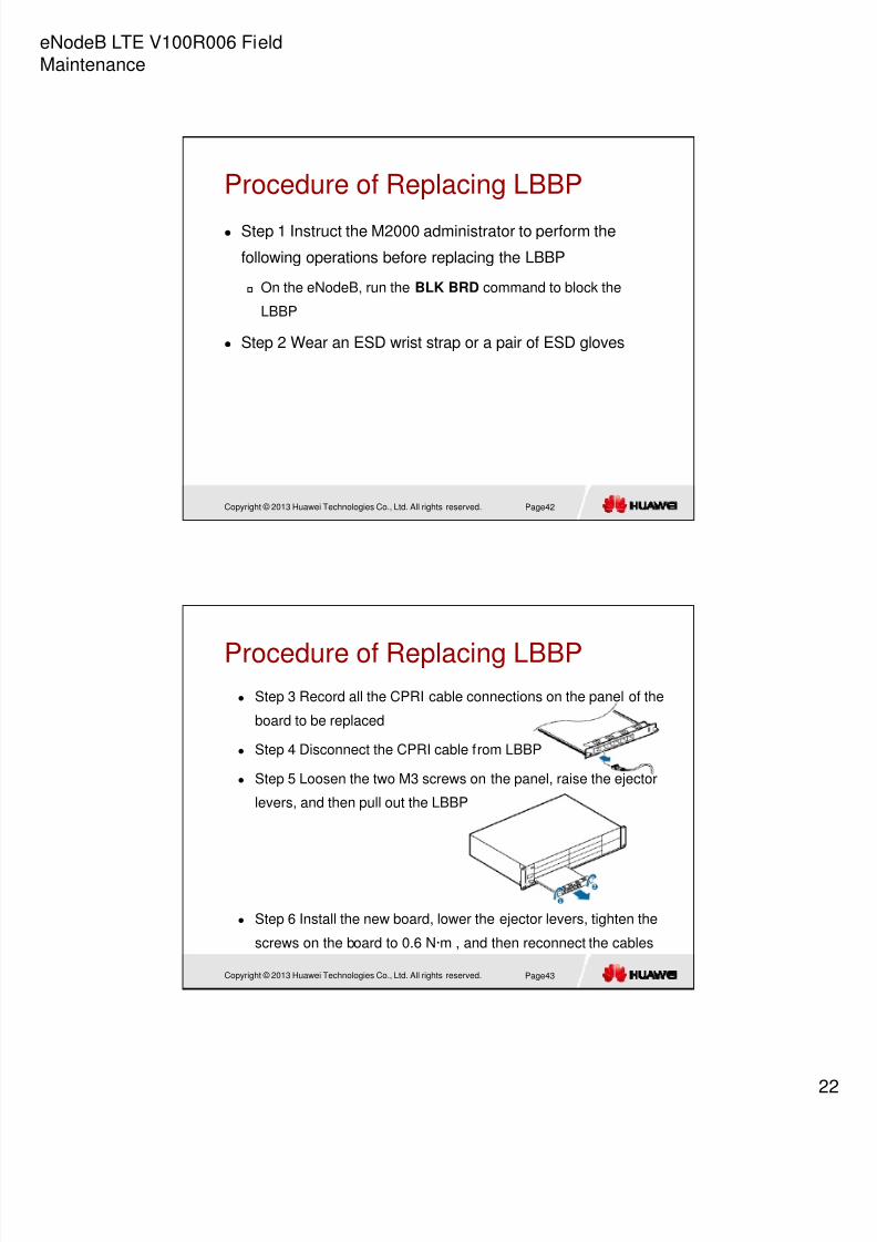
Replacing eNodeB Components
Replacing BBU3900 Components
Replacing the RFU
Replacing the RRU (For DBS3900)
Replacing a DCDU
Replacing the Fan Box
Replacing the Power Subrack
Page30
Query Electronic Label of the
Board
Replacing the BBU
Replacing the LMPT/UMPT
Replacing the LBBP
Replacing the FAN Unit
Replacing the UPEU
Replacing the UEIU
Replacing the USCU
Replacing the UBRI
Replacing the UTRP
Replacing the UCIU
Replacing the Optical Module
Copyright © 2013 Huawei Technologies Co., Ltd. All rights reserved.
Query Electronic Label of theBoard Before replacing a board, you need to query the electronic
label of the board at the remote end to confirm the type of
board to be replaced
Run the DSP BRDMFRINFO command on the LMT
Page31

8/13/2019 Microsoft PowerPoint - 03 OEB104710 eNodeB LTE V100R006 Field Maintance ISSUE 1
http://slidepdf.com/reader/full/microsoft-powerpoint-03-oeb104710-enodeb-lte-v100r006-field-maintance-issue 17/63
eNodeB LTE V100R006 Field
Maintenance
Copyright © 2013 Huawei Technologies Co., Ltd. All rights reserved.
Replacing the BBU
As the core component of an eNodeB, the BBU3900
processes baseband signals for the entire eNodeB. It also
provides transmission ports between the eNodeB and the
MME/S-GW.
Replacing the BBU disrupts all the services carried by the
eNodeB. Therefore, the BBU should be replaced within 20
minutes
Page32
Copyright © 2013 Huawei Technologies Co., Ltd. All rights reserved.
Procedure of Replacing BBU Step 1 Instruct the M2000 administrator to perform the
following operations for the replacement of the BBU
Back up the service data or transfer the service carried by the
BBU to be replaced if required
Modify the ESN in the DHCP management interface by referring
to the new BBU
Step 2 Power off the BBU according to BBU power offprocedure
Step 3 Wear an ESD wrist strap or a pair of ESD gloves
Page33

8/13/2019 Microsoft PowerPoint - 03 OEB104710 eNodeB LTE V100R006 Field Maintance ISSUE 1
http://slidepdf.com/reader/full/microsoft-powerpoint-03-oeb104710-enodeb-lte-v100r006-field-maintance-issue 18/63
eNodeB LTE V100R006 Field
Maintenance
Copyright © 2013 Huawei Technologies Co., Ltd. All rights reserved.
Procedure of Replacing BBU
Step 4 Record all the cable connections on the panels of the
boards in the BBU to be replaced
Step 5 Disconnect the power cables, transmission cables, CPRI
cables, and alarm cables from the panels of the boards in the BBU
Step 6 Loosen the four M6 screws on the BBU, and then remove
the BBU
Page34
Copyright © 2013 Huawei Technologies Co., Ltd. All rights reserved.
Procedure of Replacing BBU Step 7 Remove all the boards in the faulty BBU, install the
boards in the corresponding slots of the new BBU, and then
install filler panels in the idle slots
Step 8 Install the new BBU, tighten the screws on the BBU
Step 9 Power on the BBU, for details, see power on BBU
procedure
Step 10 Check whether the new BBU is functional according to
the status of the LEDs on the BBU
Step 11 Reapply for a license, and then install the license for the
eNodeBPage35

8/13/2019 Microsoft PowerPoint - 03 OEB104710 eNodeB LTE V100R006 Field Maintance ISSUE 1
http://slidepdf.com/reader/full/microsoft-powerpoint-03-oeb104710-enodeb-lte-v100r006-field-maintance-issue 19/63
eNodeB LTE V100R006 Field
Maintenance
Copyright © 2013 Huawei Technologies Co., Ltd. All rights reserved.
Replacing the LMPT/UMPT The LMPT/UMPT manages the entire eNodeB system in terms of OM and
signaling processing and provides the clock for the BBU3900
LMPT/UMPT board is hot-swappable
LMPT and UMPT can not work as active and standby in the same BBU3900
If a standby LMPT/UMPT is not configured, replacing the LMPT /UMPT
disrupts all services carried by the LTE. Therefore, the LMPT /UMPT should
be replaced within 10 minutes
Page36
Copyright © 2013 Huawei Technologies Co., Ltd. All rights reserved.
Prerequisite—See Remarks
Page37

8/13/2019 Microsoft PowerPoint - 03 OEB104710 eNodeB LTE V100R006 Field Maintance ISSUE 1
http://slidepdf.com/reader/full/microsoft-powerpoint-03-oeb104710-enodeb-lte-v100r006-field-maintance-issue 20/63
eNodeB LTE V100R006 Field
Maintenance
2
Copyright © 2013 Huawei Technologies Co., Ltd. All rights reserved.
Procedure of Replacing LMPT/UMPT
Step 1 Instruct the M2000 administrator to perform the following
operations before replacing the LMPT/UMPT
Back up NE configuration
Run the ULD LICENSE command to back up the license in the
LTE mode
Run the BLK CELL command to block all cells of the base station
working in LTE mode
Step 2 Wear an ESD wrist strap or a pair of ESD gloves
Step 3 Record all the cable connections on the panel of the board
to be replaced
Page38
Copyright © 2013 Huawei Technologies Co., Ltd. All rights reserved.
Procedure of Replacing LMPT/UMPT
Step 3 Record all the cable connections on the panel of the
board to be replaced
Step 4 Disconnect the cables from LMPT/UMPT
Step 5 Remove the two M3 screws on the panel, and then
pull out the LMPT/UMPT
Page39

8/13/2019 Microsoft PowerPoint - 03 OEB104710 eNodeB LTE V100R006 Field Maintance ISSUE 1
http://slidepdf.com/reader/full/microsoft-powerpoint-03-oeb104710-enodeb-lte-v100r006-field-maintance-issue 21/63
eNodeB LTE V100R006 Field
Maintenance
2
Copyright © 2013 Huawei Technologies Co., Ltd. All rights reserved.
Procedure of Replacing LMPT/UMPT
Step 6 Install the new board, tighten the screws on the
board
Step 7 Check the status of the new board by observing the
status of indicators
Step 8 Perform the following operations according to onsite
conditions of the eNodeB as in the notes, then Step 9
Step 9 Take off the ESD wrist strap or ESD gloves, and
pack up all tools.
Page40
Copyright © 2013 Huawei Technologies Co., Ltd. All rights reserved.
Replacing the LBBP The LTE Baseband Processing unit (LBBP) in the BBU3900
processes the baseband signals and CPRI signals
The LBBP board is hot-swappable
Page41
8/13/2019 Microsoft PowerPoint - 03 OEB104710 eNodeB LTE V100R006 Field Maintance ISSUE 1
http://slidepdf.com/reader/full/microsoft-powerpoint-03-oeb104710-enodeb-lte-v100r006-field-maintance-issue 22/63
eNodeB LTE V100R006 Field
Maintenance
2
Copyright © 2013 Huawei Technologies Co., Ltd. All rights reserved.
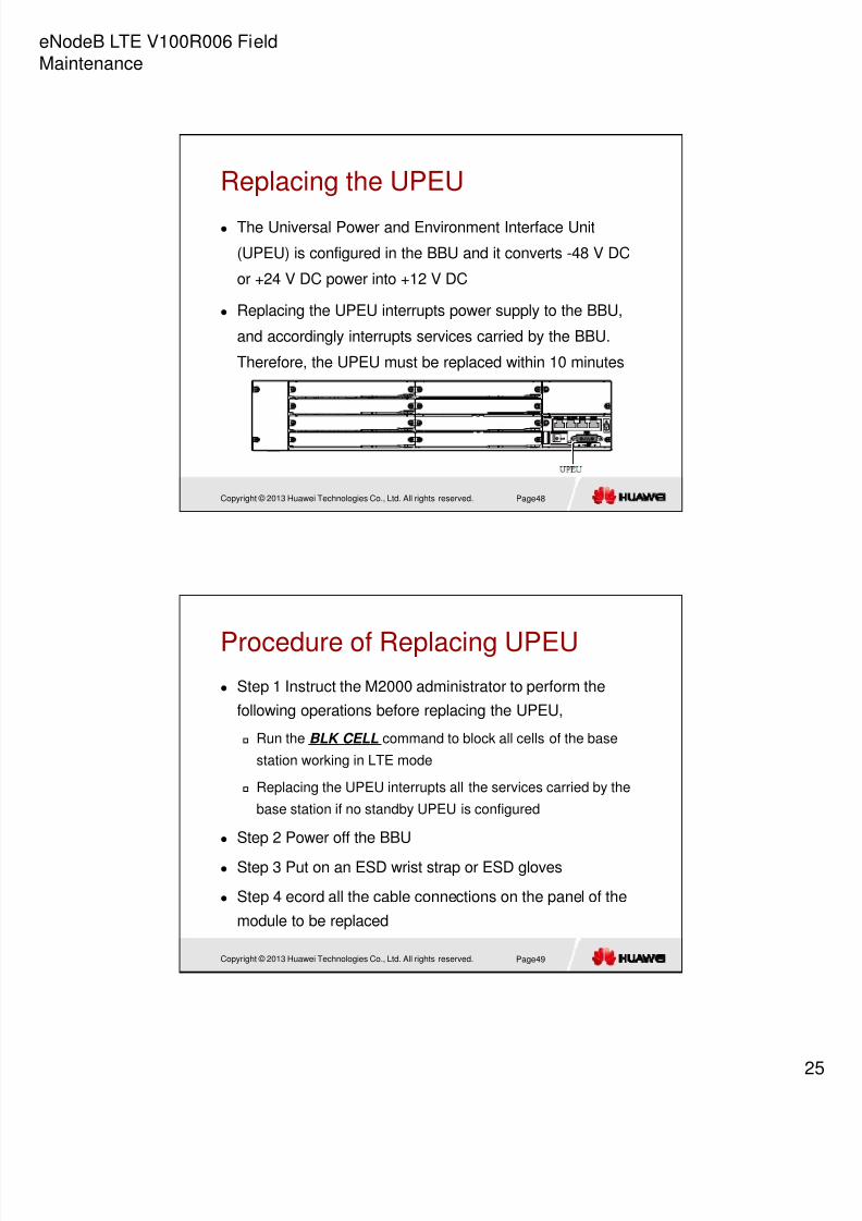
Procedure of Replacing LBBP
Step 1 Instruct the M2000 administrator to perform the
following operations before replacing the LBBP
On the eNodeB, run the BLK BRD command to block the
LBBP
Step 2 Wear an ESD wrist strap or a pair of ESD gloves
Page42
Copyright © 2013 Huawei Technologies Co., Ltd. All rights reserved.
Procedure of Replacing LBBP Step 3 Record all the CPRI cable connections on the panel of the
board to be replaced
Step 4 Disconnect the CPRI cable from LBBP
Step 5 Loosen the two M3 screws on the panel, raise the ejector
levers, and then pull out the LBBP
Step 6 Install the new board, lower the ejector levers, tighten the
screws on the board to 0.6 N·m , and then reconnect the cables
Page43

8/13/2019 Microsoft PowerPoint - 03 OEB104710 eNodeB LTE V100R006 Field Maintance ISSUE 1
http://slidepdf.com/reader/full/microsoft-powerpoint-03-oeb104710-enodeb-lte-v100r006-field-maintance-issue 23/63
eNodeB LTE V100R006 Field
Maintenance
2
Copyright © 2013 Huawei Technologies Co., Ltd. All rights reserved.
Procedure of Replacing LBBP
Step 7 Wait for about 15 minutes after the board is started, then
check the status of the new board by observing the status of
indicators
Step 8 Instruct the M2000 administrator to perform,
On the eNodeB, run the UBL BRD command to unblock the LBBP
Check whether any new alarms are generated by the base station
and handle the alams
Synchronize the inventory information manually
Ask the onsite engineers to perform dialing tests to check whether
the cells can normally provide services
Step 9 Take off the ESD wrist strap or ESD gloves, and pack up all
toolsPage44
Copyright © 2013 Huawei Technologies Co., Ltd. All rights reserved.
Replacing the FAN Unit Replacing the FAN unit may lead to overheating alarms due
to interruption of heat dissipation in the BBU. The services,
however, should not be affected
The FAN unit is hot-swappable
Replacing the FAN unit may lead to overheating alarms due
to interruption of heat dissipation in the BBU. Therefore, the
FAN unit should be replaced within three minutes
Page45

8/13/2019 Microsoft PowerPoint - 03 OEB104710 eNodeB LTE V100R006 Field Maintance ISSUE 1
http://slidepdf.com/reader/full/microsoft-powerpoint-03-oeb104710-enodeb-lte-v100r006-field-maintance-issue 24/63
eNodeB LTE V100R006 Field
Maintenance
2
Copyright © 2013 Huawei Technologies Co., Ltd. All rights reserved.
Procedure of Replacing FAN Unit
Step 1 Wear an ESD wrist strap or a pair of ESD gloves
Step 2 Remove the two M3 screws from the panel, and then
remove the FAN unit
Step 3 Install the new unit, tighten the screws on the unit
Step 4 Check the status of the indicators to determine
whether the new module works properly
Page46
Copyright © 2013 Huawei Technologies Co., Ltd. All rights reserved.
Procedure of Replacing FAN Unit Step 5 Instruct the M2000 administrator to,
Check whether any new alarms are generated by the base
station
Synchronize the inventory information manually
Step 6 Take off the ESD wrist strap or ESD gloves, and
pack up all tools
Page47
8/13/2019 Microsoft PowerPoint - 03 OEB104710 eNodeB LTE V100R006 Field Maintance ISSUE 1
http://slidepdf.com/reader/full/microsoft-powerpoint-03-oeb104710-enodeb-lte-v100r006-field-maintance-issue 25/63
eNodeB LTE V100R006 Field
Maintenance
2
Copyright © 2013 Huawei Technologies Co., Ltd. All rights reserved.
Replacing the UPEU
The Universal Power and Environment Interface Unit
(UPEU) is configured in the BBU and it converts -48 V DC
or +24 V DC power into +12 V DC
Replacing the UPEU interrupts power supply to the BBU,
and accordingly interrupts services carried by the BBU.
Therefore, the UPEU must be replaced within 10 minutes
Page48
Copyright © 2013 Huawei Technologies Co., Ltd. All rights reserved.
Procedure of Replacing UPEU Step 1 Instruct the M2000 administrator to perform the
following operations before replacing the UPEU,
Run the BLK CELL command to block all cells of the base
station working in LTE mode
Replacing the UPEU interrupts all the services carried by the
base station if no standby UPEU is configured
Step 2 Power off the BBU
Step 3 Put on an ESD wrist strap or ESD gloves
Step 4 ecord all the cable connections on the panel of the
module to be replaced
Page49

8/13/2019 Microsoft PowerPoint - 03 OEB104710 eNodeB LTE V100R006 Field Maintance ISSUE 1
http://slidepdf.com/reader/full/microsoft-powerpoint-03-oeb104710-enodeb-lte-v100r006-field-maintance-issue 26/63
eNodeB LTE V100R006 Field
Maintenance
2
Copyright © 2013 Huawei Technologies Co., Ltd. All rights reserved.
Procedure of Replacing UPEU
Step 5 Disconnect the power cable, monitoring cable, and alarm
cable from the UPEU
Step 6 Loosen the two M3 screws
on the panel, and pull out the UPEU
Step 7 Install the new board, tighten the screws on the board to 0.6
N·m, and then reconnect the cables
Step 8 Power on the BBU according to the instructions in Powering
On the BBU3900
Page50
Copyright © 2013 Huawei Technologies Co., Ltd. All rights reserved.
Procedure of Replacing UPEU Step 9 Check the status of the new board by observing the
status of indicators
Step 10 Instruct the M2000 to perform,
Run the UBL CELL command to unblock all the LTE cells
Check whether any new alarms are generated by the base
station
Synchronize the inventory information manually
Ask the onsite engineers to perform dialing tests to check
whether the cells can normally provide services
Step 11 Take off the ESD wrist strap or ESD gloves, and
pack up all toolsPage51

8/13/2019 Microsoft PowerPoint - 03 OEB104710 eNodeB LTE V100R006 Field Maintance ISSUE 1
http://slidepdf.com/reader/full/microsoft-powerpoint-03-oeb104710-enodeb-lte-v100r006-field-maintance-issue 27/63
eNodeB LTE V100R006 Field
Maintenance
2
Copyright © 2013 Huawei Technologies Co., Ltd. All rights reserved.
Replacing the UEIU
The Universal Environment Interface Unit (UEIU) provides
channels for transmitting the monitoring signals from external
equipment to the BBU
The UEIU is hot-swappable
Replacing the UEIU may cause the failure to monitor the
external equipment. Therefore, the UEIU must be replaced
within 5 minutes
Page52
Copyright © 2013 Huawei Technologies Co., Ltd. All rights reserved.
Procedure of Replacing UEIU Step 1 Wear an ESD wrist strap or a pair of ESD gloves
Step 2 Record all cable connections on panel of the board to be
replaced
Step 3 Disconnect the monitoring cable and alarm cable from the
UEIU
Step 4 Loosen the two M3 screws on the panel, and pull out the
UEIU
Page53

8/13/2019 Microsoft PowerPoint - 03 OEB104710 eNodeB LTE V100R006 Field Maintance ISSUE 1
http://slidepdf.com/reader/full/microsoft-powerpoint-03-oeb104710-enodeb-lte-v100r006-field-maintance-issue 28/63
eNodeB LTE V100R006 Field
Maintenance
2
Copyright © 2013 Huawei Technologies Co., Ltd. All rights reserved.
Procedure of Replacing UEIU
Step 5 Install the new board, tighten the screws on the
board to 0.6 N·m, and then reconnect the cables
Step 6 Instruct the M2000 to perform,
Check whether any new alarms are generated by the base
station
Synchronize the inventory information manually
Step 7 Take off the ESD wrist strap or ESD gloves, and
pack up all tools
Page54
Copyright © 2013 Huawei Technologies Co., Ltd. All rights reserved.
Replacing the USCU The Universal Satellite card and Clock Unit (USCU) in the
BBU receives clock signals such as the GPS, RGPS, BITS,
and M-1PPS signals. In addition, it transmits or receives
1PPS+TOD clock signals
The USCU board is hot-swappable
Page55

8/13/2019 Microsoft PowerPoint - 03 OEB104710 eNodeB LTE V100R006 Field Maintance ISSUE 1
http://slidepdf.com/reader/full/microsoft-powerpoint-03-oeb104710-enodeb-lte-v100r006-field-maintance-issue 29/63
eNodeB LTE V100R006 Field
Maintenance
2
Copyright © 2013 Huawei Technologies Co., Ltd. All rights reserved.
Procedure of Replacing USCU
Step 1 Wear an ESD wrist strap or a pair of ESD gloves
Step 2 Record all cable connections on panel of the board to be
replaced
Step 3 Disconnect the GPS clock signal cable from the USCU
Step 4 Loosen the two M3 screws on the panel, raise the ejector
levers, and then pull out the USCU
Page56
Copyright © 2013 Huawei Technologies Co., Ltd. All rights reserved.
Procedure of Replacing USCU Step 5 Install the new board, lower the ejector levers, tighten
the screws on the board to 0.6 N·m and then reconnect the
cables
Step 6 Check the status of the new board by observing the
status of indicators
Step 7 Instruct the M2000 administrator to perform,
Check whether any new alarms are generated by the base station
Synchronize the inventory information manually
Step 8 Take off the ESD wrist strap or ESD gloves, and pack
up all toolsPage57

8/13/2019 Microsoft PowerPoint - 03 OEB104710 eNodeB LTE V100R006 Field Maintance ISSUE 1
http://slidepdf.com/reader/full/microsoft-powerpoint-03-oeb104710-enodeb-lte-v100r006-field-maintance-issue 30/63

8/13/2019 Microsoft PowerPoint - 03 OEB104710 eNodeB LTE V100R006 Field Maintance ISSUE 1
http://slidepdf.com/reader/full/microsoft-powerpoint-03-oeb104710-enodeb-lte-v100r006-field-maintance-issue 31/63
eNodeB LTE V100R006 Field
Maintenance
3
Copyright © 2013 Huawei Technologies Co., Ltd. All rights reserved.
Procedure of Replacing UTRP
Step 6 Set the DIP switches on the new board according to the settings of
the DIP switches on the replaced board. For details about the DIP switch
Step 7 Install the new board, lower the ejector levers, tighten the screws
on the board to 0.6 N·m and then reconnect the cables
Step 8 Check the status of the new board by observing the status of
indicators.
Step 9 Instruct the M2000 administrator to perform,
On the eNodeB, run the UBL CELL command to unblock all LTE cells
Check whether any new alarms are generated by the base station
Synchronize the inventory information manually
Ask the onsite engineers to perform dialing tests to check whether the cells can
normally provide services
Step 10 Take off the ESD wrist strap or ESD gloves, and pack up all tools
Page60
Copyright © 2013 Huawei Technologies Co., Ltd. All rights reserved.
Replacing the UBRI The Universal BaseBand Radio Interface Board (UBRI)
provides ports for CPRI cables
Replacing the UBRI interrupts all the services carried on the
board
The UBRI board is hot-swappable
Page61

8/13/2019 Microsoft PowerPoint - 03 OEB104710 eNodeB LTE V100R006 Field Maintance ISSUE 1
http://slidepdf.com/reader/full/microsoft-powerpoint-03-oeb104710-enodeb-lte-v100r006-field-maintance-issue 32/63
eNodeB LTE V100R006 Field
Maintenance
3
Copyright © 2013 Huawei Technologies Co., Ltd. All rights reserved.
Procedure of Replacing UBRI
Step 1 Instruct the M2000 administrator to perform
On the eNodeB, run the BLK CELL command to block all the
cells
Step 2 Put on an ESD wrist strap or ESD gloves
Step 3 Record all the cable connections on the panel of the
board to be replaced
Step 4 Disconnect CPRI cables from the board
Step5 Loosen the two M3 screws on the panel,
raise the ejector levers, and then pull out the UBRI
Page62
Copyright © 2013 Huawei Technologies Co., Ltd. All rights reserved.
Procedure of Replacing UBRI Step 6 Install the new board, lower the ejector levers, tighten the
screws on the board to 0.6 N·m and then reconnect the cables
Step 7 Check the status of the new board by observing the status of
indicators
Step 8 Instruct the M2000 administrator to perform,
On the eNodeB, run the UBL CELL command to unblock all LTE cells
Check whether any new alarms are generated by the base station
Synchronize the inventory information manually
Ask the onsite engineers to perform dialing tests to check whether the
cells can normally provide services
Step 9 Take off the ESD wrist strap or ESD gloves, and pack up all
tools Page63

8/13/2019 Microsoft PowerPoint - 03 OEB104710 eNodeB LTE V100R006 Field Maintance ISSUE 1
http://slidepdf.com/reader/full/microsoft-powerpoint-03-oeb104710-enodeb-lte-v100r006-field-maintance-issue 33/63
eNodeB LTE V100R006 Field
Maintenance
3
Copyright © 2013 Huawei Technologies Co., Ltd. All rights reserved.
Replacing the UCIU
The Universal inter-Connection Infrastructure Unit (UCIU)
interconnects BBUs. It forwards control and synchronization
information from one BBU to another
The UCIU is hot-swappable
Page64
Copyright © 2013 Huawei Technologies Co., Ltd. All rights reserved.
Procedure of Replacing UCIU Step 1 Put on an ESD wrist strap or ESD gloves
Step 2 Record all the cable connections on the panel of the
board to be replaced
Step 3 Disconnect the interconnection cable between the
optical ports on the UCIU
Step 4 Loosen the two M3 screws on the panel,
raise the ejector levers, and then pull out the UCIU
Page65

8/13/2019 Microsoft PowerPoint - 03 OEB104710 eNodeB LTE V100R006 Field Maintance ISSUE 1
http://slidepdf.com/reader/full/microsoft-powerpoint-03-oeb104710-enodeb-lte-v100r006-field-maintance-issue 34/63
eNodeB LTE V100R006 Field
Maintenance
3
Copyright © 2013 Huawei Technologies Co., Ltd. All rights reserved.
Procedure of Replacing UCIU
Step 5 Install the new board, lower the ejector levers, tighten the
screws on the board to 0.6 N·m and then reconnect the cables
Step 6 Check the status of the new board by observing the status of
indicators
Step 7 Instruct the M2000 administrator to perform,
Check whether any new alarms are generated by the base station
Synchronize the inventory information manually
Ask the onsite engineers to perform dialing tests to check whether the
cells can normally provide services
Step 8 Take off the ESD wrist strap or ESD gloves, and pack up all
toolsPage66
Copyright © 2013 Huawei Technologies Co., Ltd. All rights reserved.
Replacing the Optical Module The optical module is used for the optical transmission
between the BBU and other devices
Optical modules are hot-swappable
Replacing the optical module interrupts the services carried on
this port
Page67

8/13/2019 Microsoft PowerPoint - 03 OEB104710 eNodeB LTE V100R006 Field Maintance ISSUE 1
http://slidepdf.com/reader/full/microsoft-powerpoint-03-oeb104710-enodeb-lte-v100r006-field-maintance-issue 35/63
eNodeB LTE V100R006 Field
Maintenance
3
Copyright © 2013 Huawei Technologies Co., Ltd. All rights reserved.
Procedure of Replacing theOptical Module Step 1 Put on an ESD wrist strap or ESD gloves
Step 2 Loosen the screws on the cover plate of the
RRU cabling cavity using an M4 Phillips
screwdriver, and then open the cover plate.
Step 3 Record the connections of the optical
module and optical fibers.
Step 4 Press the latch on the optical fiber
connector, and then remove the connector from the
faulty optical module.
Page68
Copyright © 2013 Huawei Technologies Co., Ltd. All rights reserved.
Procedure of Replacing the Optical
Module Step 5 Lower the puller on the faulty optical module, and then pull the
puller until the optical module is removed from the RRU.
Step 6 Choose the optical module of the same type as the faulty optical
module according to the label on the module. Install the new optical
module into the RRU.
Step 7 Insert the optical fiber connector into the new optical module.
Step 8 Check the operating status of the new RRU by observing the
status of RRU indicators.
Step 9 Reconnect the cables in the cabling cavity.
Page69

8/13/2019 Microsoft PowerPoint - 03 OEB104710 eNodeB LTE V100R006 Field Maintance ISSUE 1
http://slidepdf.com/reader/full/microsoft-powerpoint-03-oeb104710-enodeb-lte-v100r006-field-maintance-issue 36/63
eNodeB LTE V100R006 Field
Maintenance
3
Copyright © 2013 Huawei Technologies Co., Ltd. All rights reserved.
Procedure of Replacing the OpticalModule
Step 10 Close the cabling cavity of the RRU and use an M4
Phillips screwdriver to tighten the screws on the cover plate for
the cabling cavity.
Step 11 Take off the ESD gloves, and pack up all the tools.
Page70
Copyright © 2013 Huawei Technologies Co., Ltd. All rights reserved.
Replacing the RFU The RFU is a radio frequency unit. Replacing
an RFU interrupts the services carried on the
RFU
Replacing an RFU disrupts the services
carried on the RFU
It takes about 6 to 10 minutes to replace an
RFU
The handle is used during the RFU
replacement. The handle is placed in the slot
at the upper right inside the cabinet door
Page71

8/13/2019 Microsoft PowerPoint - 03 OEB104710 eNodeB LTE V100R006 Field Maintance ISSUE 1
http://slidepdf.com/reader/full/microsoft-powerpoint-03-oeb104710-enodeb-lte-v100r006-field-maintance-issue 37/63
eNodeB LTE V100R006 Field
Maintenance
3
Copyright © 2013 Huawei Technologies Co., Ltd. All rights reserved.
Procedure of Replacing RFU Optional Step 1 If the RFU is functional and is to be replaced as a
spare part, check whether the maximum transmit power of the
RFU to be replaced is locked if it is functional
If the maximum transmit power of the RFU is locked, set the
maximum transmit power to 0 before placing the RFU in the
storehouse of spare parts
To check whether a maximum transmit power is locked for an
RFU,
Run the DSP RRU command to query the maximum output power of
the TX channels of the RFU
Set the maximum transmit power for the RFU to 0 to disable thelocking for the maximum transmit power
Run the LOC RRUTC command to disable the maximum output power
locking for TX channels of the RFU
Page72
Copyright © 2013 Huawei Technologies Co., Ltd. All rights reserved.
Procedure of Replacing RFU Step 2 Instruct the M2000 administrator to
run the BLK BRD command to block the faulty RFU
Step 3 Verify that TX channels of the RFU are disabled. In this
situation, the ACT indicator on the RFU panel blinks at 0.5 Hz
Step 4 Wear the ESD wrist strap or ESD gloves
Step 5 Turn off the switch for DC power output for the RFU on
the direct current distribution unit (DCDU) to power off the
RFU
Page73

8/13/2019 Microsoft PowerPoint - 03 OEB104710 eNodeB LTE V100R006 Field Maintance ISSUE 1
http://slidepdf.com/reader/full/microsoft-powerpoint-03-oeb104710-enodeb-lte-v100r006-field-maintance-issue 38/63
eNodeB LTE V100R006 Field
Maintenance
3
Copyright © 2013 Huawei Technologies Co., Ltd. All rights reserved.
Procedure of Replacing RFU
Step 6 Label the power cable for the faulty RFU, and then
disconnect the cable
Step 7 Label the RF jumper of the faulty RFU, loosen the DIN
7/16 elbow male connector of the RF jumper, and disconnect
the RF jumper
Step 8 Label the common public radio interface (CPRI) cable
for the RFU, and disconnect the CPRI cable
Page74
Copyright © 2013 Huawei Technologies Co., Ltd. All rights reserved.
Procedure of Replacing RFU Step 9 Loosen the screws at the four corners of
the RFU using a Phillips screwdriver, and then
pull the RFU using the handle to move it
outwards 50 mm to 100 mm
Use one hand to hold the RFU and use the other
hand to pull the RFU out of the cabinet.
Page75

8/13/2019 Microsoft PowerPoint - 03 OEB104710 eNodeB LTE V100R006 Field Maintance ISSUE 1
http://slidepdf.com/reader/full/microsoft-powerpoint-03-oeb104710-enodeb-lte-v100r006-field-maintance-issue 39/63
eNodeB LTE V100R006 Field
Maintenance
3
Copyright © 2013 Huawei Technologies Co., Ltd. All rights reserved.
Procedure of Replacing RFU
Step 10 Put the faulty RFU into an ESD box, and then place the
handle back to the original position
Step 11 Place the new RFU on the corresponding guide rails,
and then slide it along the rails until it is in position
Step 12 Tighten the captive screws at the four corners of the
panel of the RFU to secure the RFU on the subrack
Page76
Copyright © 2013 Huawei Technologies Co., Ltd. All rights reserved.
Procedure of Replacing RFU Step 13 Insert the CPRI cable into the panel of the new
RFU according to the labels
Step 14 Connect the labeled RF jumper to the new RFU,
and tighten the DIN male elbow connector to 25 N·m to 35
N·m using a torque wrench
Step 15 Connect the labeled power cable to the new RFU
and secure the cable
Page77

8/13/2019 Microsoft PowerPoint - 03 OEB104710 eNodeB LTE V100R006 Field Maintance ISSUE 1
http://slidepdf.com/reader/full/microsoft-powerpoint-03-oeb104710-enodeb-lte-v100r006-field-maintance-issue 40/63
eNodeB LTE V100R006 Field
Maintenance
4
Copyright © 2013 Huawei Technologies Co., Ltd. All rights reserved.
Procedure of Replacing RFU
Step 16 Turn on the switch for DC output power on the DCDU to power
on the RFU
Step 17 Check the operating status of the RFU by observing indicator
status
Step 18 Optional: Set the maximum output power locking for TX
channels of the RFU
Run the LOC RRUTC command to set the maximum output power of the
RFU
Run the RST BRD command to reset the RFU
Run the DSP TXBRANCH command to check whether the maximum outputpower of each RFU is set successfully
Page78
Copyright © 2013 Huawei Technologies Co., Ltd. All rights reserved.
Procedure of Replacing RFU Step 19 Instruct the M2000 administrator to
Run the BLK BRD command to unblock the RFU on the
eNodeB
Step 20 Take off the ESD wrist strap or gloves, and then
pack up all the tools
Page79

8/13/2019 Microsoft PowerPoint - 03 OEB104710 eNodeB LTE V100R006 Field Maintance ISSUE 1
http://slidepdf.com/reader/full/microsoft-powerpoint-03-oeb104710-enodeb-lte-v100r006-field-maintance-issue 41/63
eNodeB LTE V100R006 Field
Maintenance
4
Copyright © 2013 Huawei Technologies Co., Ltd. All rights reserved.
Replacing the RRU
A distributed base station consists of RRUs and a BBU
Replacing an RRU interrupts all the services carried by the
RRU, and alarms are generated
It takes about 6 to 10 minutes to replace an RRU, which
involves disconnecting the cables, removing screws,
removing the faulty RRU, inserting a new RRU, tightening
the screws, connecting the cables to the new RRU, and
loading the software
Page80
Copyright © 2013 Huawei Technologies Co., Ltd. All rights reserved.
Procedure of Replacing RRU Optional Step 1 If an RRU to be replaced is not faulty, store
it in the spare parts inventory after the maximum output
power locking for TX channels is disabled for the RRU
Check the maximum output power locking for TX channels of
the target RRU
Run the DSP RRU command to query the maximum output power
of the TX channels of the RRU
Set the maximum output power of the TX channels of the RRUto 0 and disable the maximum output power locking
run the LOC RRUTC command to disable the maximum output
power locking for TX channels of the RRU
Page81

8/13/2019 Microsoft PowerPoint - 03 OEB104710 eNodeB LTE V100R006 Field Maintance ISSUE 1
http://slidepdf.com/reader/full/microsoft-powerpoint-03-oeb104710-enodeb-lte-v100r006-field-maintance-issue 42/63
eNodeB LTE V100R006 Field
Maintenance
4
Copyright © 2013 Huawei Technologies Co., Ltd. All rights reserved.
Procedure of Replacing RRU
Step 2 Instruct the M2000 administrator to
run the BLK BRD command to block the RRU On the eNodeB
Step 3 Power off the RRU by referring to Powering Off an
RRU
Step 4 Wear ESD gloves
Step 5 Loosen the screws on the cover plate of the RRU
cabling cavity using an M4 Phillips screwdriver for common
RRU or M5 Phillips screwdriver for 12L blade RRU, and then
open the cover plate
Page82
Copyright © 2013 Huawei Technologies Co., Ltd. All rights reserved.
Procedure of Replacing RRU Step 6 Record all the cable connections on the module to be
replaced.
Step 7 Disconnect cables from the cabling cavity and bottom panel
Step 8 For the 12L blade RRU , If the RRU installed in centralized
mode is to be replaced, first use an M6 Phillips screwdriver to loosen
the two screws on the metal sheet of the RRU and remove the metal
sheet, as shown in following f igure. For the common RRU, Loosen
the captive screws on the two hoist clamps on the main mounting
bracket using an M4 Phillips screwdriver.
Page83

8/13/2019 Microsoft PowerPoint - 03 OEB104710 eNodeB LTE V100R006 Field Maintance ISSUE 1
http://slidepdf.com/reader/full/microsoft-powerpoint-03-oeb104710-enodeb-lte-v100r006-field-maintance-issue 43/63

8/13/2019 Microsoft PowerPoint - 03 OEB104710 eNodeB LTE V100R006 Field Maintance ISSUE 1
http://slidepdf.com/reader/full/microsoft-powerpoint-03-oeb104710-enodeb-lte-v100r006-field-maintance-issue 44/63
eNodeB LTE V100R006 Field
Maintenance
4
Copyright © 2013 Huawei Technologies Co., Ltd. All rights reserved.
Procedure of Replacing RRU
Step 10 Tighten the captive screws on the two hoist clamps on the
main mounting bracket to 1.4 N·m (12.39 lbf·in.) using an M4 torque
screwdriver. Install a new RRU and then waterproof the RRU
Step 11 Reconnect all required cables, and verify that vacant cable
troughs in the cabling cavity are equipped by waterproof blocks
Step 12 Close the cover plate of the RRU cabling cavity, and then
tighten the protection screw on the cover plate of the RRU cabling
cavity using an M4 torque screwdriver
Step 13 Power on the RRU by referring to Powering On an RRU
Step 14 Check the operating status of the new RRU by observingthe status of RRU indicators. For details, see the description of
RRU indicators in the RRU Hardware Description
Page86
Copyright © 2013 Huawei Technologies Co., Ltd. All rights reserved.
Procedure of Replacing RRU Step 15 Optional: Set the maximum output power locking
for TX channels of the RRU
Run the LOC RRUTC command to set the maximum output
power of the RRU
Run the RST BRD command to reset the RRU
Run the DSP TXBRANCH command to check whether the
maximum output power of each RRU is set successfully
Step 16 Unblock the RRU
run the UBL BRD command to unblock the RRU
Step 17 Take off the ESD gloves, and pack up all the tools
Page87

8/13/2019 Microsoft PowerPoint - 03 OEB104710 eNodeB LTE V100R006 Field Maintance ISSUE 1
http://slidepdf.com/reader/full/microsoft-powerpoint-03-oeb104710-enodeb-lte-v100r006-field-maintance-issue 45/63
eNodeB LTE V100R006 Field
Maintenance
4
Copyright © 2013 Huawei Technologies Co., Ltd. All rights reserved.
Replacing the DCDU
The DCDU, installed under the BBU3900, supplies DC
power for the cabinet.
DCDU-03B for BTS3900A(ver.B) and DBS3900;
DCDU-11B for BTS3900A(ver.C) and DBS3900;
DCDU-12B for BTS3900A(ver.D) and DBS3900;
Replacing the DCDU disrupts the services carried on the
corresponding cabinet.
It takes about 20 minutes to replace the DCDU.
Page88
Copyright © 2013 Huawei Technologies Co., Ltd. All rights reserved.
Procedure of Replacing DCDU Step 1 Wear an ESD wrist strap or a pair of ESD gloves
Step 2 Modify the administrative state and block all RRUs
powered by the DCDU to be replaced.
Step 3 (Optional) Before replacing a DCDU-03B or DCDU-
11B, record the status of circuit breakers SW0 to SW9 on
the DCDU, and set all the circuit breakers to OFF. If a
DCDU-12B is to be replaced, skip this step.
Page89

8/13/2019 Microsoft PowerPoint - 03 OEB104710 eNodeB LTE V100R006 Field Maintance ISSUE 1
http://slidepdf.com/reader/full/microsoft-powerpoint-03-oeb104710-enodeb-lte-v100r006-field-maintance-issue 46/63
eNodeB LTE V100R006 Field
Maintenance
4
Copyright © 2013 Huawei Technologies Co., Ltd. All rights reserved.
Procedure of Replacing DCDU
Step 4 Disconnect the DCDU from power supply provided
by the power equipment.
Step 5 Record the installation positions (DC output ports) of
all connectors on the DCDU, and remove the connectors.
Page90
Copyright © 2013 Huawei Technologies Co., Ltd. All rights reserved.
Procedure of Replacing DCDU Step 6 Use a Phillips screwdriver to remove the protective
cover from the DC input wiring terminal block of the DCDU,
as shown in the following figure.
Page91

8/13/2019 Microsoft PowerPoint - 03 OEB104710 eNodeB LTE V100R006 Field Maintance ISSUE 1
http://slidepdf.com/reader/full/microsoft-powerpoint-03-oeb104710-enodeb-lte-v100r006-field-maintance-issue 47/63
eNodeB LTE V100R006 Field
Maintenance
4
Copyright © 2013 Huawei Technologies Co., Ltd. All rights reserved.
Procedure of Replacing DCDU
Step 7 Record the connection of the DC input power cables, and
disconnect the power cables.
Step 8 Use a Phillips screwdriver to remove the two screws from each
side of the DCDU, and pull the DCDU out of the cabinet along the guide
rails gently, as shown in the following figure.
Page92
Copyright © 2013 Huawei Technologies Co., Ltd. All rights reserved.
Procedure of Replacing DCDU Step 9 Place the new DCDU on the installation position, and
gently push it into the cabinet along the guide rails. Tighten
the two M6 screws on each side of the DCDU to 2 N·m
(17.7 lbf·in.).
Step 10 Remove the protective cover for the DC input wiring
terminal block from the new DCDU, reconnect the power
cables to the new DCDU according to the recordedinstallation positions, and then reinstall the protective cover.
Page93

8/13/2019 Microsoft PowerPoint - 03 OEB104710 eNodeB LTE V100R006 Field Maintance ISSUE 1
http://slidepdf.com/reader/full/microsoft-powerpoint-03-oeb104710-enodeb-lte-v100r006-field-maintance-issue 48/63
eNodeB LTE V100R006 Field
Maintenance
4
Copyright © 2013 Huawei Technologies Co., Ltd. All rights reserved.
Procedure of Replacing DCDU
Step 11 Reinstall the other cables to the new DCDU
according to the recorded installation positions.
Step 12 Turn on the switch on the power equipment for the
DCDU to power on the DCDU.
Step 13 According to the recorded status of the circuit
breakers on the DCDU, turn on the circuit breakers that
were set to OFF in 3.
Page94
Copyright © 2013 Huawei Technologies Co., Ltd. All rights reserved.
Procedure of Replacing DCDU Step 14 Check the indicators on the RRUs according to the
following table to verify that these RRUs are properly powered by
the DCDU.
Step 15 Take off the ESD wrist strap or ESD gloves, and pack up
all tools.Page95
ITEM NORMAL STATUS
Indicators on the RRU panel • RUN indicator: blinking (on for 0.125s and off for 0.125s, or
on for 1s and off f or 1s)
• ALM indicator: steady off
Indicators on the BBU • UPEU: The RUN indicator is steady on.
• FAN: The STATE indicator is blinking green.
• The normal status of the indicators on the BBU is as
follows:
RUN indicator: blinking green (on for 1s and off f or 1s)
ALM indicator: steady off
ACT indicator: steady on

8/13/2019 Microsoft PowerPoint - 03 OEB104710 eNodeB LTE V100R006 Field Maintance ISSUE 1
http://slidepdf.com/reader/full/microsoft-powerpoint-03-oeb104710-enodeb-lte-v100r006-field-maintance-issue 49/63
eNodeB LTE V100R006 Field
Maintenance
4
Copyright © 2013 Huawei Technologies Co., Ltd. All rights reserved.
Replacing the Fan Box
The fan box works with the air inlet box in the cabinet to
form a ventilation loop, and provides forced ventilation
Replacing the fan box may result in over-temperature
alarms due to interruption of heat dissipation for the cabinet,
but services of the base station are not affected
It takes about 20 minutes to replace a fan box
Page96
Copyright © 2013 Huawei Technologies Co., Ltd. All rights reserved.
Procedure of Replacing FAN Box Step 1 Wear an ESD wrist strap or a pair of ESD gloves
Step 2 Set the DC power switch labeled FAN on the DCDU-
01 to OFF. Below figure shows the position of the power
switch on the DCDU-01 for the fan box ear an ESD wrist
strap or a pair of ESD gloves
Page97

8/13/2019 Microsoft PowerPoint - 03 OEB104710 eNodeB LTE V100R006 Field Maintance ISSUE 1
http://slidepdf.com/reader/full/microsoft-powerpoint-03-oeb104710-enodeb-lte-v100r006-field-maintance-issue 50/63
eNodeB LTE V100R006 Field
Maintenance
5
Copyright © 2013 Huawei Technologies Co., Ltd. All rights reserved.
Procedure of Replacing FAN Box
Step 3 Label the cables on
the panel of the fan box and
then remove the cables
Step 4 Loosen the captive
screws on both sides of the
adjustable cable trough.
Then, raise the cable trough
and fix it at the upper
mounting hole, as shown in
Right figure
Page98
Copyright © 2013 Huawei Technologies Co., Ltd. All rights reserved.
Procedure of Replacing FAN Box Step 5 Remove the four screws from the fan box. Pull out the
fan box by one-third of its length with one hand by using the
handle key, hold the fan box with the other hand, and then
pull the entire fan box out of the cabinet, as shown in Right
Figure . Then, put the faulty fan box into an ESD box
Page99

8/13/2019 Microsoft PowerPoint - 03 OEB104710 eNodeB LTE V100R006 Field Maintance ISSUE 1
http://slidepdf.com/reader/full/microsoft-powerpoint-03-oeb104710-enodeb-lte-v100r006-field-maintance-issue 51/63
eNodeB LTE V100R006 Field
Maintenance
5
Copyright © 2013 Huawei Technologies Co., Ltd. All rights reserved.
Procedure of Replacing FAN Box
Step 6 Install the new fan box. Then, secure the four screws
Step 7 Place the adjustable cable trough to its original
position, and then tighten the captive screws on both sides of
the adjustable cable trough
Step 8 Install the cables to the panel of the fan box based on
the labels
Step 9 Set the switch on the DCDU-01 for the fan box to ON
Step 10 Wear an ESD wrist strap or a pair of ESD gloves
Page100
Copyright © 2013 Huawei Technologies Co., Ltd. All rights reserved.
Replacing an EPS 01 Subrack Replacing an EPS subrack interrupts the services carried on
a base station.
Replacing an EPS takes about 30 minutes.
The following figure shows the position of the EPS subrack
in an APM30H.
Page101

8/13/2019 Microsoft PowerPoint - 03 OEB104710 eNodeB LTE V100R006 Field Maintance ISSUE 1
http://slidepdf.com/reader/full/microsoft-powerpoint-03-oeb104710-enodeb-lte-v100r006-field-maintance-issue 52/63
eNodeB LTE V100R006 Field
Maintenance
5
Copyright © 2013 Huawei Technologies Co., Ltd. All rights reserved.
Replacing an EPS 01 Subrack
Step 1 Put on an ESD wrist strap or a pair of ESD gloves.
Step 2 Set the BAT and PSU circuit breaker on the EPS
subrack to OFF.
Step 3 Switch off external AC power supply to the APM30H.
Step 4 Disconnect the ground cable for the EPS subrack
from the ground bar on the inner left wall of the cabinet.
Step 5 Remove the PMU and all PSUs from the EPS
subrack.
Page102
Copyright © 2013 Huawei Technologies Co., Ltd. All rights reserved.
Replacing an EPS 01 Subrack Step 6 Use a Phillips screwdriver to remove the cable tray
from the right side of the EPS subrack.
Step 7 Label the cables delivered with the EPS subrack on
the right side of the EPS subrack, and remove the cables.
Step 8 Remove the screws from the AC protective cover on
the EPS subrack, and then remove the AC protective cover.
Step 9 Label the AC input and output power cables
delivered with the EPS subrack on the left side of the EPS
subrack, and remove the cables.
Page103

8/13/2019 Microsoft PowerPoint - 03 OEB104710 eNodeB LTE V100R006 Field Maintance ISSUE 1
http://slidepdf.com/reader/full/microsoft-powerpoint-03-oeb104710-enodeb-lte-v100r006-field-maintance-issue 53/63
eNodeB LTE V100R006 Field
Maintenance
5
Copyright © 2013 Huawei Technologies Co., Ltd. All rights reserved.
Replacing an EPS 01 Subrack
Step 10 bel the DC output power cables delivered with the
EPS subrack on the right side of the EPS subrack, and
remove the cables.
Step 11 Remove the remaining seven screws from both
sides of the EPS subrack, and pull the EPS subrack out of
the cabinet along the guide rails, as shown in the following
figure.
Step 12 Push the new EPS subrack into the cabinet alongthe guide rails, and tighten the seven screws on the EPS
subrack to 2 N·m (17.7 lbf·in.) and the one hexagonal screw
to 3 N·m (26.55 lbf·in.). Page104
Copyright © 2013 Huawei Technologies Co., Ltd. All rights reserved.
Replacing an EPS 01 Subrack Step 13 (Optional) If the faulty EPS subrack uses 220 V AC
three-phase input power, the short-circuiting bars at the AC
INPUT terminals on the new EPS subrack must be
removed.
Step 14 Reinstall the PMU and all PSUs in the
corresponding slots in the EPS subrack.
Step 15 Connect the new power series 120 connector to theremoved cable tray, and reinstall the cable tray onto the
right inner side of the cabinet.
Page105
8/13/2019 Microsoft PowerPoint - 03 OEB104710 eNodeB LTE V100R006 Field Maintance ISSUE 1
http://slidepdf.com/reader/full/microsoft-powerpoint-03-oeb104710-enodeb-lte-v100r006-field-maintance-issue 54/63
eNodeB LTE V100R006 Field
Maintenance
5
Copyright © 2013 Huawei Technologies Co., Ltd. All rights reserved.
Replacing an EPS 01 Subrack
Step 16 Reinstall cables on the EPS subrack according to
attached labels.
Step 17 Install the AC protective cover on the left AC input
area of the EPS subrack, and tighten the screw on the
cover.
Step 18 Restore external AC power supply to the APM30H.
Step 19 Set the PSU and PSU circuit breakers on the EPS
subrack to ON.
Page106
Copyright © 2013 Huawei Technologies Co., Ltd. All rights reserved.
Replacing an EPS 01 Subrack Step 20 Observe the status of indicators on the PMU and
PSUs to determine whether the new EPS subrack is
working properly.
When the PMU is working properly, the RUN indicator is
blinking green, and the ALM indicator is steady off.
When the PSUs are working properly, the power indicators are
steady green, and the protection indicators and alarm
indicators are steady off.
Step 21 Take off the ESD wrist strap or ESD gloves, and
pack up all tools.
Page107

8/13/2019 Microsoft PowerPoint - 03 OEB104710 eNodeB LTE V100R006 Field Maintance ISSUE 1
http://slidepdf.com/reader/full/microsoft-powerpoint-03-oeb104710-enodeb-lte-v100r006-field-maintance-issue 55/63
eNodeB LTE V100R006 Field
Maintenance
5
Copyright © 2013 Huawei Technologies Co., Ltd. All rights reserved.
Replacing a PMU 01B
The PMU is hot-
swappable.
Replacing a PMU takes
about 5 minutes.
The position of the PMU
varies with the base
station type. The right
figure shows thepositions of the PMU.
Page108
Copyright © 2013 Huawei Technologies Co., Ltd. All rights reserved.
Replacing a PMU 01B Step 1 Put on an ESD wrist strap or a pair of ESD gloves.
Step 2 Record the cable connections on the panel of the
PMU to be replaced and disconnect the cables from the
PMU.
Step 3 Use a Phillips screwdriver to remove the two screws
from the handle on the panel of the PMU.
Step 4 Gently pull the handle to slide the PMU out of the
subrack and remove the PMU from the subrack.
Page109

8/13/2019 Microsoft PowerPoint - 03 OEB104710 eNodeB LTE V100R006 Field Maintance ISSUE 1
http://slidepdf.com/reader/full/microsoft-powerpoint-03-oeb104710-enodeb-lte-v100r006-field-maintance-issue 56/63
eNodeB LTE V100R006 Field
Maintenance
5
Copyright © 2013 Huawei Technologies Co., Ltd. All rights reserved.
Replacing a PMU 01B
Step 5 Take out a new PMU, and set the DIP switch on the
PMU panel according to the setting of the DIP switch on the
faulty PMU. The following figure shows the position of the
DIP switch.
Step 6 Install the new PMU.
Step 7 Check the status of indicators on the new PMU to
determine whether the new PMU is working properly.
Step 8 Take off the ESD wrist strap or ESD gloves, andpack up all tools.
Page110
Copyright © 2013 Huawei Technologies Co., Ltd. All rights reserved.
Replacing a PSU (EPW30-48A) The PSU is hot-
swappable.
Replacing a PSU takes
about 3 minutes.
The position of the PSU
varies with the base
station type. The rightfigure shows the position
of the PSU.
Page111

8/13/2019 Microsoft PowerPoint - 03 OEB104710 eNodeB LTE V100R006 Field Maintance ISSUE 1
http://slidepdf.com/reader/full/microsoft-powerpoint-03-oeb104710-enodeb-lte-v100r006-field-maintance-issue 57/63
eNodeB LTE V100R006 Field
Maintenance
5
Copyright © 2013 Huawei Technologies Co., Ltd. All rights reserved.
Replacing a PSU (EPW30-48A)
Step 1 Put on an ESD wrist strap or a pair of ESD gloves.
Step 2 Use a screwdriver to loosen the screws on the ejector lever
on the panel of the PSU.
Step 3 Gently pull the ejector lever to slide the PSU out of the
subrack and remove the PSU from the subrack.
Page112
Copyright © 2013 Huawei Technologies Co., Ltd. All rights reserved.
Replacing a PSU (EPW30-48A) Step 4 Install a new PSU.
Use a screwdriver to loosen the screws on the ejector lever of
the PSU, and raise the ejector lever.
Slide the PSU along the guide rails into the subrack until it
snaps shut, and lower the ejector lever.
Slide the PSU along the guide rails into the subrack until it
snaps shut, and lower the ejector lever.
Page113

8/13/2019 Microsoft PowerPoint - 03 OEB104710 eNodeB LTE V100R006 Field Maintance ISSUE 1
http://slidepdf.com/reader/full/microsoft-powerpoint-03-oeb104710-enodeb-lte-v100r006-field-maintance-issue 58/63
eNodeB LTE V100R006 Field
Maintenance
5
Copyright © 2013 Huawei Technologies Co., Ltd. All rights reserved.
Replacing a PSU (EPW30-48A)
Step 5 Check the status of indicators on the new PSU to
determine whether the new PSU is working properly. When the
new PSU is working properly, the power indicator is steady green,
and the protection indicator and alarm indicator are steady off.
Step 6 Take off the ESD wrist strap or ESD gloves, and pack up
all tools.
Page114
Copyright © 2013 Huawei Technologies Co., Ltd. All rights reserved. Page115
Contents1. Local Operation and Maintenance Introduction
2. Power on and Power off Procedure of eNodeB
3. Replacing Components of eNodeB
4. Maintenance items for eNodeB

8/13/2019 Microsoft PowerPoint - 03 OEB104710 eNodeB LTE V100R006 Field Maintance ISSUE 1
http://slidepdf.com/reader/full/microsoft-powerpoint-03-oeb104710-enodeb-lte-v100r006-field-maintance-issue 59/63
eNodeB LTE V100R006 Field
Maintenance
5
Copyright © 2013 Huawei Technologies Co., Ltd. All rights reserved.
Equipment Room MaintenanceItems
Item Interval Operation Instruction Reference Standard
Environmentalalarms
Daily Check whether powersupply alarms, fire alarms,
or smoke alarms are
reported
No power supplyalarms, fire alarms,
or smoke alarms are
reported.
Temperaturein
the equipmentroom
Weekly Record the temperatureshown on the thermometer
in the equipment room.
The normaltemperature
ranges from -20° Cto +55
°
C.
Humidity inthe
equipmentroom
Weekly Record the humidity shownon the hygrometer in the
equipment room.
The normal humidityranges from 5% RH
to 95% RH.
Illumination in
the equipment
room
Every
two
months
Check whether the routine
and emergency illumination
in equipment room isnormal
-
Page116
Copyright © 2013 Huawei Technologies Co., Ltd. All rights reserved.
Equipment Room Maintenance ItemsItem Interval Operation Instruction Reference
Standard
Air
conditioner
Every
two
months
Check whether the air conditioner is
working normally.
-
Protectivedevices
Everytwo
months
Check whether anti-disasterdevices, equipment
protection devices, and fire
protectiondevices are in
good condition.
There is nodanger of
damage to
theequipment by
rats or insects.
EquipmentRoom
cleanlines
s
Everytwo
months
Check whether cabinets,equipment housing,
equipment interior, tables, floor,
doors, and windows are clean.
All the itemsto be checked
are clean.
Page117

8/13/2019 Microsoft PowerPoint - 03 OEB104710 eNodeB LTE V100R006 Field Maintance ISSUE 1
http://slidepdf.com/reader/full/microsoft-powerpoint-03-oeb104710-enodeb-lte-v100r006-field-maintance-issue 60/63
eNodeB LTE V100R006 Field
Maintenance
6
Copyright © 2013 Huawei Technologies Co., Ltd. All rights reserved.
Power Supply and Grounding SystemMaintenance Items
Page118
Item Interval OperationInstruction
Reference Standard
Powercables
Monthly Check theconnections of power
cables carefully.
The power cables are notaging, and there is no
corrosion on theconnection points
Voltage Monthly Measure the voltage
of the power supply
usinga multimeter.
The voltage is within
normal range
PGND
cables
Monthly Check whether the
PGND cable and
ground bar areconnected properly.
The connections of the
PGND cable are secure.
The cable is not aging.The connection points are
sound with no corrosionon them.
Copyright © 2013 Huawei Technologies Co., Ltd. All rights reserved.
Power Supply and Grounding SystemMaintenance Items
Page119
Item Interval Operation Instruction Reference Standard
CheckingEarth
resistance
Monthly Measure the earthresistance using an
electric earthresistance
tester and keep a
record.
The groundingresistance of the cabinet
is smallerthan 10 ohms.
Batteries Annually Check the batteriesand
rectifiers.
The battery capacity iswithin normal range and
the batteries arecorrectly
connected. Theperformance parametersof rectifiers are normal.

8/13/2019 Microsoft PowerPoint - 03 OEB104710 eNodeB LTE V100R006 Field Maintance ISSUE 1
http://slidepdf.com/reader/full/microsoft-powerpoint-03-oeb104710-enodeb-lte-v100r006-field-maintance-issue 61/63
eNodeB LTE V100R006 Field
Maintenance
6
Copyright © 2013 Huawei Technologies Co., Ltd. All rights reserved.
Main Components Maintenance Items
Page120
Item Interval OperationInstruction
Reference Standard
Fans Monthly Check whetherthe fans are
operational.
The fans work properlywithout exceptional sounds
generated by frictionsbetween the blades of the fan
and the subrack.
LEDs on the
boards
Monthly Check whether
the LEDs on theboards are normal.
For details about the status of
LEDs, see the hardwaredescription about the
corresponding boards.
Air filter Quarterl
y
If there is too
much dust on theair filter, clean the
air filter
Copyright © 2013 Huawei Technologies Co., Ltd. All rights reserved.
Main Components MaintenanceItems
Page121
Item Interval Operation Instruction Reference Standard
Exterior ofthe cabinet
Quarterly
Check whether there aredents, cracks, holes, or
corrosion on the surfaceof the cabinet and
whether the cabinet label
is legible.
-
Lock anddoor of the
Cabinet
Quarterly
Check whether the lock isnormal and the door can
beopened and closed easily.
-
Cabinetcleanliness
Quarterly
Check whether thecabinet is clean.
The cabinet surface isclean. The subracks
arenot dusty.

8/13/2019 Microsoft PowerPoint - 03 OEB104710 eNodeB LTE V100R006 Field Maintance ISSUE 1
http://slidepdf.com/reader/full/microsoft-powerpoint-03-oeb104710-enodeb-lte-v100r006-field-maintance-issue 62/63
eNodeB LTE V100R006 Field
Maintenance
6
Copyright © 2013 Huawei Technologies Co., Ltd. All rights reserved.
Main Components Maintenance Items
Page122
Item Interval Operation Instruction Reference Standard
ESD wriststrap
Quarterly
Use either of the followingmethods:
Use an ESD wrist strap
tester to test the ESDwrist
strap.Use a multimeter to test
theearth resistance of the
ESD
wrist strap.
If you are using anESD wrist strap tester,
the LED GOOD is on.
If you are using amultimeter, the earth
resistance is between0.75 MΩ and 10 MΩ.
Fan box Annually If there is too much dust
on the surface of or insidethe fan box, clean the fan
box.
-
Copyright © 2013 Huawei Technologies Co., Ltd. All rights reserved. Page123
Summary Maintenance methods of eNodeB
Power on and Power off procedure and key points
Basic operations of local operation and maintenance
Routine maintenance items of equipment and evirement

8/13/2019 Microsoft PowerPoint - 03 OEB104710 eNodeB LTE V100R006 Field Maintance ISSUE 1
http://slidepdf.com/reader/full/microsoft-powerpoint-03-oeb104710-enodeb-lte-v100r006-field-maintance-issue 63/63
eNodeB LTE V100R006 Field
Maintenance
Thank youwww.huawei.com