microprocessor ph/orp analyzer - emersonmodel 1054b ph/orp table of contents model 1054b ph/orp...
TRANSCRIPT

����������� ����Microprocessor pH/ORP Analyzer
Instruction ManualPN 51-1054BpH/rev.BApril 2003

WARNINGELECTRICAL SHOCK HAZARD
Making cable connections to and servicingthis instrument require access to shockhazard level voltages which can causedeath or serious injury.
Relay contacts made to separate powersources must be disconnected beforeservicing.
Electrical installation must be in accor-dance with the National Electrical Code(ANSI/NFPA-70) and/or any other appli-cable national or local codes.
Unused cable conduit entries must besecurely sealed by non-flammable clo-sures to provide enclosure integrity incompliance with personal safety andenvironmental protection requirements.
For safety and proper performance thisinstrument must be connected to aproperly grounded three-wire powersource.
Proper relay use and configuration isthe responsibility of the user.
Do not operate this instrument withoutfront cover secured. Refer installation,operation and servicing to qualified per-sonnel.
ESSENTIAL INSTRUCTIONSREAD THIS PAGE BEFORE PROCEED-
ING!
Rosemount Analytical designs, manufactures, and tests itsproducts to meet many national and international standards.Because these instruments are sophisticated technical prod-ucts, you must properly install, use, and maintain them toensure they continue to operate within their normal specifica-tions. The following instructions must be adhered to and inte-grated into your safety program when installing, using, andmaintaining Rosemount Analytical products. Failure to followthe proper instructions may cause any one of the following sit-uations to occur: Loss of life; personal injury; property dam-age; damage to this instrument; and warranty invalidation.
• Read all instructions prior to installing, operating, and serv-icing the product. If this Instruction Manual is not the correctmanual, telephone 1-949-757-8500 and the requestedmanual will be provided. Save this Instruction Manual forfuture reference.
• If you do not understand any of the instructions, contactyour Rosemount representative for clarification.
• Follow all warnings, cautions, and instructions marked onand supplied with the product.
• Inform and educate your personnel in the proper installa-tion, operation, and maintenance of the product.
• Install your equipment as specified in the InstallationInstructions of the appropriate Instruction Manual and perapplicable local and national codes. Connect all products tothe proper electrical and pressure sources.
• To ensure proper performance, use qualified personnel toinstall, operate, update, program, and maintain the product.
• When replacement parts are required, ensure that qualifiedpeople use replacement parts specified by Rosemount.Unauthorized parts and procedures can affect the product’sperformance and place the safe operation of your processat risk. Look alike substitutions may result in fire, electricalhazards, or improper operation.
• Ensure that all equipment doors are closed and protectivecovers are in place, except when maintenance is being per-formed by qualified persons, to prevent electrical shock andpersonal injury.
WARNINGThis product is not intended for use in the light industrial, residential or commercial environment, per the instrument’s certifi-cation to EN50081-2. Be sure to disconnect all hazardous voltage before opening. The unused conduit openings need to be sealed with NEMA 4X or IP65 conduit plugs to maintain the ingress protection rat-ing (IP65). No external connection to the instrument of more than 60VDC or 43V peak allowed with the exception of powerand relay terminals. Any violation will impair the safety protection provided.
Emerson Process Management
Rosemount Analytical Inc.2400 Barranca ParkwayIrvine, CA 92606 USATel: (949) 757-8500Fax: (949) 474-7250
http://www.RAuniloc.com
© Rosemount Analytical Inc. 2001


MODEL 1054B pH/ORP TABLE OF CONTENTS
MODEL 1054B pH/ORPMICROPROCESSOR ANALYZER
TABLE OF CONTENTSSection Title Page
1.0 DESCRIPTION AND SPECIFICATIONS ................................................................ 11.1 Features and Applications ....................................................................................... 11.2 Physical Specifications-General .............................................................................. 21.3 Instrument Specifications......................................................................................... 2
2.0 INSTALLATION....................................................................................................... 32.1 General .................................................................................................................... 32.2 Unpacking and Inspection ....................................................................................... 32.3 Mechanical Installation ............................................................................................ 32.4 Electrical Wiring....................................................................................................... 4
3.0 DESCRIPTION OF CONTROLS............................................................................. 143.1 Keyboard Functions................................................................................................. 14
4.0 CONFIGURATION................................................................................................... 184.1 Configuration ........................................................................................................... 184.2 Alarm 1 and 2 ......................................................................................................... 234.3 Interval Timer .......................................................................................................... 244.4 Temperature ............................................................................................................ 254.5 Current Output ........................................................................................................ 254.6 pH Electrode Diagnostics ........................................................................................ 264.7 Solution Temperature Compensation and Isopotential Point................................... 274.8 Defaults.................................................................................................................... 284.9 Automatic Buffer Mode ............................................................................................ 294.10 Alarm Setpoint ......................................................................................................... 304.11 Output Scale Expansion .......................................................................................... 314.12 Simulate Current Output .......................................................................................... 32
5.0 START- UP AND CALIBRATION ........................................................................... 335.1 Start- Up and Calibration ......................................................................................... 335.2 Temperature Calibration .......................................................................................... 335.3 Buffer Calibration ..................................................................................................... 335.4 pH Standardization .................................................................................................. 345.5 pH Glass Slope........................................................................................................ 345.6 Sensor Maintenance................................................................................................ 345.7 Standard ORP Solution ........................................................................................... 355.8 ORP Standardization............................................................................................... 365.9 Sensor Maintenance................................................................................................ 36
6.0 KEYBOARD SECURITY......................................................................................... 376.1 Keyboard Security ................................................................................................... 37
7.0 THEORY OF OPERATION...................................................................................... 387.1 Theory of Operation (pH)......................................................................................... 387.2 Theory of Operation (ORP)...................................................................................... 38
i

MODEL 1054B pH/ORP TABLE OF CONTENTS
TABLE OF CONTENTS CONT’D.Section Title Page
8.0 DIAGNOSTICS AND TROUBLESHOOTING ...................................... 398.1 Diagnostics ........................................................................................... 398.2 Troubleshooting .................................................................................... 428.3 Instrument Maintenance ....................................................................... 42
9.0 RETURN OF MATERIALS................................................................... 449.1 General................................................................................................. 449.2 Warranty Repair.................................................................................... 449.3 Non Warranty Repair ............................................................................ 44
LIST OF FIGURESFigure No. Title Page
2-1 Panel Mounting Cutout ......................................................................... 52-2 Panel Mounting Tab Installation............................................................ 62-3 Wall Mounting J-Box Installation........................................................... 72-4 Wall Mounting J-Box Wiring.................................................................. 82-5 Pipe Mounting Installation .................................................................... 92-6 Electrical Wiring.................................................................................... 102-7 Integral Preamp Wiring......................................................................... 112-8 Wall Mount Enclosure (Option -20)....................................................... 122-9 Integral Preamp Wiring for Group II Wall Mount Enclosure.................. 133-1 LCD Display.......................................................................................... 154-1 Menu Items (pH)................................................................................... 194-2 Set Function Menu (ORP) .................................................................... 214-3 Interval Timer Example......................................................................... 244-4 Alarm Setpoint ...................................................................................... 304-5 Output Scale Expansion ....................................................................... 314-6 Simulate Current Output....................................................................... 32
LIST OF TABLESTable No. Title Page
3-1 Key Description .................................................................................... 163-2 Information Mnemonics ........................................................................ 173-3 Set Function Mnemonics ...................................................................... 174-1 Configuration Work Sheet (pH) ............................................................ 204-2 Configuration Worksheet (ORP)........................................................... 224-3 Relay States For Various Analyzer Conditions & Alarm/Default Config. 284-4 Buffer Standards................................................................................... 295-1 ORP of Saturated Quinhydrone Solution.............................................. 358-1 Fault Mnemonics .................................................................................. 398-2 RTD Resistance Values........................................................................ 398-3 Troubleshooting Guide (pH) ................................................................. 408-4 Troubleshooting Guide (ORP) .............................................................. 418-5 Sensor Input to Analyzer vs. pH at Four Temperatures........................ 428-6 Replacement Parts ............................................................................... 438-7 Accessories .......................................................................................... 438-8 Ordering Information............................................................................. 43
ii

1
MODEL 1054B pH/ORP SECTION 1.0DESCRIPTION AND SPECIFICATIONS
SECTION 1.0DESCRIPTION AND SPECIFICATIONS
• pH ELECTRODE DIAGNOSTICS warn user of the need for calibration or electrode replace-ment.
• AUTOMATIC BUFFER RECOGNITION with stored buffer-temperature curves(1054B pH only).
• NEMA 4X (IP65) WEATHERPROOF CORROSION-RESISTANT ENCLOSURE.
• NO BATTERY BACK-UP REQUIRED. Non-volatile EEPROM memory.
• SPECIFIC PROCESS TEMPERATURE COMPENSATION for pH changes due to tempera-ture (1054B pH only).
1.1 FEATURES AND APPLICATIONS
The Model 1054B Microprocessor Analyzers, with theappropriate sensor, are designed to continuously mea-sure and control pH, ORP, conductivity, percent concen-tration, ratio, resistivity, ozone, dissolved oxygen and totalfree chlorine in industrial and municipal processes.
The Model 1054B is housed in a NEMA 4X (IP65)weatherproof corrosion-resistant, flame retardantenclosure suitable for panel, pipe or wall mounting. Allfunctions are accessed through the front panel mem-brane keyboard which features tactile feedback.Measurement data may be read at any time; however,settings may be protected against accidental or unau-thorized changes by a user selectable security code.The display indicates the measured value in engineer-ing units as well as temperature, alarm status, holdoutput and fault conditions.
The analyzer transmits an isolated current output whichis continuously expandable over the measurementrange for either direct or reverse action. A hold outputfunction is available for allowing manual control duringroutine sensor maintenance. During hold mode the out-put will be at a preset or last process value.
In the event of one of the following conditions, theanalyzer will drive the output to a preset value in addi-tion to displaying a fault code. The Model 1054B pH’scontinuous self diagnostics alert the user to the follow-ing:
With automatic buffer recognition, the analyzer recog-nizes the buffers, then calculates the electrode slopeusing stored pH-temperature curves for ten commonbuffers.
Dual alarms are a standard feature on the Model1054B and are programmable for either high or lowoperation. Alarm 2 may be programmed to activate inevent of a failure detected by the continuous diagnos-tics. Both alarms feature independent setpoints,adjustable hysteresis and time delay action. A dedicat-ed interval timer with relay is also provided for chemicalor ultrasonic cleaning.
The 1054B pH automatically compensates the pHreading for process temperature changes. Automaticor manual temperature compensation is keyboardselectable. Additional process temperature compen-sation is available.
The Analyzer includes a 0.7 inch digital display avail-able in LCD or LED format.
The Model 1054B can display the process tempera-ture in °F or °C.
• Broken or cracked electrode
• Worn out or non-immersedelectrode
• Calibration or coated elec-trode warning
• Faulty slope value (off-lineonly)
• Open wiring
• Analyzer electronics failure
• Faulty temperature element ortemperature value

2
MODEL 1054B pH/ORP SECTION 1.0DESCRIPTION AND SPECIFICATIONS
1.2 PHYSICAL SPECIFICATIONSEnclosure: Black, ABS, NEMA 4X, IP65,
CSA Enclosure 4144 X 144 X 192 mm (5.7 X 5.7 X 7.6 in.)
Wall Mount Enclosure: NEMA 4X, Heavy duty fiberglass, reinforced thermoplastic.356.4 X 450.1 X 180.2 mm* (14 X 17.7 X 7.1 in.*)
Front Panel: Membrane keyboard with tactile feedback and user selectable security
Digital Display: LCD, black on greyOptional, red LED Character Height: 18 mm (0.7 in.)
Electrical Classification:FM Class I, Div. 2, Group A thru D
28 Vdc relays - 5.0 amps resistive only150 mA - Groups A & B; 400 mA - Group C ; 540mA - Group D; Ci = 0; Li = 0
CSA Class I, Div. 2, Group A thru D.28 Vdc, 110 Vac & 230 Vac relays 5.0 Amps resistive only
Wall Mount Enclosure: General PurposePower: 100 - 127 VAC, 50/60 Hz ±6%, 4.0 W
200 - 253 VAC, 50/60 Hz ±6%, 4.0 WCurrent Output: Isolated, 0-20 mA or 4-20 mA into
600 ohms maximum load at 115/230 Vac or 550ohms maximum load at 100/200 Vac, Direct orReverse Output Dampening: 0-255 seconds.
Code -20 Wall Mount Enclosure does not meet CE requirements*Includes latches and mounting feet
The Model 1054B pH Analyzer requires a preamplifier to con-vert the high impedance pH glass electrode signal to a lowimpedance signal. The preamplifier may be located in one ofthree areas; in the pH sensor for best performance, in a remotejunction box when process temperatures exceed 80°C (176°F)in submersion applications, or in the analyzer when the distancebetween the pH sensor and the analyzer is 4.5 meters (15 ft) orless. The result is that the pH signal may then be reliably trans-mitted from the sensor to the analyzer using standard shielded4-wire instrument cable.
The Model 1054B pH measures over the full range of 0-14 pH.The current output may be calibrated to represent any 1 to 14pH span.
A two-point calibration is made by immersing the sensor in twodifferent buffer solutions and entering the pH values. When twobuffers are used, the microprocessor automatically calculatesthe electrode slope which is used for self-diagnostics. This elec-trode slope can be read on the display and manually adjusted.A one point process standardization is also easily accom-plished by entering the pH value of a grab sample.
INSTRUMENT SPECIFICATIONS @ 25°CMeasurement Range: 0 to 14 pHOutput Scale Expansion: Zero suppression: up to 13 pH units
Span: Any pH from 1 to 14Accuracy: ±0.01 pHRepeatability: ±0.01 pHStability: ±0.01 pH/month, non-cumulativeTemperature Coefficient: Input: ±0.003 pH/°C
Output: ±0.006 pH/°CTemperature Compensation: Pt100 RTD, Automatic
or Manual -15 to 100°C (5 to 212°F)
EMI/RFI: EN61326
LVD: EN61010-1Ambient Humidity: LED max 95% RH
(LCD max 85% RH @ 50°C)Ambient Temperature: -10 to 65°C (14 to 149°F)Alarms: Dual, field selectable High/Low, High/High,
Low/Low Alarm 2 configurable as a fault alarmTime Delay 0 to 255 secondsDual Setpoints, continuously adjustableHysteresis is adjustable up to 2 pH units or 25% full scale for low side/High Alarm and high side/Low Alarm
Interval Timer: Interval: Minimum 10 minutesOn Counts: 1 to 60On Duration: 1 to 299 secondsOff Duration: 1 to 299 secondsWait Duration: 1 to 299 secondsControls dedicated relay
Relay Contacts: Epoxy Sealed Form A contacts, SPST, Normally Open.
Resistive Inductive28 Vdc 5.0 Amps 3.0 Amps115 Vac 5.0 Amps 3.0 Amps230 Vac 5.0 Amps 1.5 Amps
Weight/Shipping Weight: 1.1 kg/1.6 kg (2.5 lb/3.5 lb)
The Model 1054B ORP Analyzer measures over thefull range of -1500 mV to +1500 mV full scale userselectable in either the American convention(Oxidation Reduction Potential), or the Europeanconvention (Reduction Oxidation-Redox). Althoughtemperature compensation is not required for ORPmeasurements, the process temperature is meas-ured and displayed. Temperature measurement ismade by a Pt 100 RTD located in the sensor assem-bly.
INSTRUMENT SPECIFICATIONS @ 25°CMeasurement Range: -1500 to +1500 mVOutput Scale Expansion:
Zero suppression: up to ±1500 mVSpan: ±1500 mV
Accuracy: ±1.0 mVRepeatability: ±1.0 mVStability: ±1.0 mV/month, non-cumulativeTemperature Coefficient: Input: ±0.2 mV/°C
Output: ±0.4 mV/°CTemperature Measurement: -15 to 100°C
(5 to 212°F)
*Model 1054B pH includes programmable temperature correction requiredfor the presence of ammonia when used in treating high purity water.
1.3 INSTRUMENT SPECIFICATIONS
3
MODEL 1054B pH/ORP SECTION 2.0INSTALLATION
SECTION 2.0INSTALLATION
2.1 GENERAL. This analyzer's enclosure is suitablefor outdoor use. However it should be located in anarea where temperature extremes and vibrations areminimized or absent. Installation must be performedby a trained technician.
2.2 UNPACKING AND INSPECTION. Inspect theanalyzer for shipping damage. If damaged, notify thecarrier immediately. Confirm that all items shown onthe packing list are present. Notify RosemountAnalytical if items are missing.
2.3 MECHANICAL INSTALLATION. Select an instal-lation site that is at least one foot from any high volt-age conduit, has easy access for operating personnel,and is not in direct sunlight. Mount the Model 1054Bas follows:
1. Remove the four screws that secure the rearcover of the enclosure (not required for wallmounting, options 20 or 21). The latching hard-ware for panel and pipe mounting is locatedinside the rear cover.
2. For standard panel and pipe mounting, removethe four screws holding the front panel assemblyof the enclosure and carefully pull the front paneland connected printed circuit boards straight out.
3. Follow the procedure for the appropriate mount-ing configuration: Section 2.3.1 for panel mount-ing, Section 2.3.2 for wall mounting, or Section2.3.3 for pipe mounting.
2.3.1 Panel Mounting (Standard). The Model 1054Bis designed to fit into a DIN standard 137.9 mm X137.9 mm (5.43 in. X 5.43 in.) panel cutout (refer toFigures 2-1 and 2-2).
1. Prepare the analyzer as described in Section 2.3.
2. Install the mounting latches as shown in Figure 2-2 (latches are shown oversize for clarity). If thelatches are not installed exactly as shown, theywill not work correctly. The screws provided areself-tapping. Tap the screw the full depth of themounting latch (refer to side view) leaving a gapgreater than the thickness of the cutout panel.
3. Align the latches as shown and insert the analyz-er enclosure through the front of the panel cutout.Tighten the screws for a firm fit. To avoid damag-ing the mounting latches, do not use excessiveforce.
4. Replace the front panel assembly. Circuit boardsmust align with the slots on the inside of the enclo-sure. Replace the door and four front panel screws.
2.3.2 Wall Mounting (P/N 23054-01). Refer toFigures 2-3 and 2-4. The integral preamp (P/N23363-00) should not be used with this option.
1. Prepare the analyzer as described in Section 2.3.
2. Mount the junction box and bracket to the analyz-er with the hardware provided. All wiring can bebrought to the terminal strip prior to mounting theanalyzer.
3. Place the metal stiffener on the inside of the ana-lyzer and mount the two ¼-inch conduit fittingsusing two each weather seals as shown. MountNEMA 4X conduit plug (included) into center con-duit hole.
4. Mount the analyzer to the junction box using the1/2-inch conduit fittings.
5. Complete wiring from the 1054B to the junctionbox (Figure 2-4).
2.3.3 Pipe Mounting (P/N 23053-00). The 2-inch pipemounting bracket includes a metal plate with a cutoutfor the 1054B refer to Section 2.3 for mounting theanalyzer into the plate. Mounting details are shown inFigure 2-5.
2.3.4 Wall Mounting Enclosure (Option -20). Referto Figure 2-8. In this configuration, the analyzer ishoused in NEMA 4X heavy duty enclosure and maybe mounted on a wall or handrail. Sufficient clearanceshould be provided in front of the enclosure to permitopening the door, which is hinged on the left side.
NOTEThe user must provide a means to discon-nect the main power supply in the form ofcircuit breaker or switch. The circuit break-er or the switch must be located in closeproximity to the instrument and identifiedas the disconnecting device for the instru-ment.
2.4.1 Power Input Wiring. The Model 1054B can beconfigured for either 115 VAC or 230 VAC power.
Connect AC power to TB1-7 and -8 (230V), or TB1-8and -9 (115 VAC) ground to the TB3-8 (refer toFigure 2-6).
1. AC connections and grounding must be in com-pliance with UL 508 and/or local electrical codes.
2. The metal stiffener is required to provide supportand proper electrical continuity between conduitfittings.
3. This type 4/4X enclosure requires a conduit hubor equivalent that provides watertight connect,REF UL 508-26.10.
4. Watertight fittings/hubs that comply with therequirements of UL 514B are to be used.
5. Conduit hubs are to be connected to the conduitbefore the hub is connected to the enclosure, REFUL 508-26.10.
6. If the metal support plate is not used, plastic fit-tings must be used to prevent structural damageto the enclosure. Also, appropriate grounding lugand awg conductor must be used with the plasticfittings.
2.4.2 Output Wiring. The signal output and alarmconnections are made to terminals 1 through 6 of TB1and terminals 1 and 2 of TB3 (refer to Figure 2-6).
CAUTIONThe sensitivity and stability of the analyzerwill be impaired if the input wiring is notgrounded. DO NOT apply power to theanalyzer until all electrical connections areverified and secure. The following precau-tions are a guide using UL 508 as a safe-guard for personnel and property.
4
MODEL 1054B pH/ORP SECTION 2.0INSTALLATION
2.4 ELECTRICAL WIRING. The Model 1054B hasthree conduit openings in the bottom rear of theanalyzer housing which will accommodate 1/2-inchconduit fittings. From a back view, the conduit open-ing on the left is for timer, alarm, and AC connec-tions; the center is for signal output and the openingon the right is for sensor wiring. AC power wiringshould be 14 gauge or greater.
The wall mount enclosure has three 3/4-inch conduitopenings, two with 3/4-inch fittings and one with aNEMA 4X conduit plug. From the front view theconduit opening on the left is for sensor wiring; thecenter is for signal output, and the right is for timer,alarm and AC power supply connections. Sensorwiring should always be run in a separate conduitfrom power wiring.
NOTEWall mount: use opening on the left for sensorwiring (refer to Figure 2-4 for wiring).
NOTEPN 23363-00 (integral preamplifier). Refer toFigure 2-7 for installation and wiring. PN 23508-00 (integral preamp is for wall mount enclo-sure). Refer to Figure 2-9.
NOTEFor maximum EMI/RFI protection the outputcable should be shielded and enclosed in anearth grounded, rigid metal conduit. Whenwiring directly to the instrument connect theoutput cable‘s outer shield to the transmitter’searth ground via terminal 8 on TB3, Fig. 2-6.When wiring to the wall mounting junction boxconnect the output cable’s outer shield to earthground via terminal 6 of TB-A, Fig. 2-4.
The sensor cable should also be shielded.When wiring directly to the instrument connectthe sensor cable’s outer shield to the transmit-ter’s earth ground via terminal 8 of TB2, Fig. 2-6. If the sensor cable’s outer shield is braid anappropriate metal cable gland fitting may beused to connect the braid to earth ground viathe instrument case. When wiring to the wallmounting junction box connect the cable’souter shield to earth ground via terminal 6 ofTB-A, Fig. 2-4.

5
FIGURE 2-1. Panel Mounting Cutout
MODEL 1054B pH/ORP SECTION 2.0INSTALLATION
WHEN INCH AND METRIC DIMSARE GIVEN
MILLIMETERINCH
DWG. NO. REV.
41054B01 B

6
MODEL 1054B pH/ORP SECTION 2.0INSTALLATION
FIGURE 2-2. Panel Mounting Tab Installation
DWG. NO. REV.
41054A26 A

7
MODEL 1054B pH/ORP SECTION 2.0INSTALLATION
FIGURE 2-3. Wall Mounting J-Box Installation
DWG. NO. REV.
41054A27 A
ITEM PART NUMBER DESCRIPTION QUANTITY
1 23058-01 S Assy, J-Box 12 33030-00 Bracket, wall mtg 13 9900600 Nut, 6-32 Hex 44 9910600 Washer, Flat #6 45 9910610 Washer, Lock Int. #6 86 9600612 Screw, 6-32 X .75 47 9510048 Seal, Weathertight 1

MODEL 1054B pH/ORP SECTION 2.0INSTALLATION
8
FIGURE 2-4. Wall Mounting J-Box Wiring
DWG. NO. REV.
41054B13 B
WHEN INCH AND METRIC DIMSARE GIVEN
MILLIMETERINCH

MODEL 1054B pH/ORP SECTION 2.0INSTALLATION
9
FIGURE 2-5. Pipe Mounting Installation
WHEN INCH AND METRIC DIMSARE GIVEN
MILLIMETERINCH
DWG. NO. REV.
41054B02 C

10
MODEL 1054B pH/ORP SECTION 2.0INSTALLATION
FIGURE 2-6. Electrical Wiring
DWG. NO. REV.
41054B03 C

11
MODEL 1054B pH/ORP SECTION 2.0INSTALLATION
FIGURE 2-7. Integral Preamp Wiring
DWG. NO. REV.
41054B32 B

12
MODEL 1054B pH/ORP SECTION 2.0INSTALLATION
FIGURE 2-8. Wall Mount Enclosure (Option -20)
DWG. NO. REV.
41054B43 A
WHEN INCH AND METRIC DIMSARE GIVEN
MILLIMETERINCH

13
MODEL 1054B pH/ORP SECTION 2.0INSTALLATION
FIGURE 2-9. Integral Preamp Wiring for Group II Wall Mount Enclosure
DWG. NO. REV.
41054B44 A
MILLIMETERINCH

14
MODEL 1054B pH/ORP SECTION 3.0DESCRIPTION OF CONTROLS
SECTION 3.0DESCRIPTION OF CONTROLS
3.1 KEYBOARD FUNCTIONS.
All functions of the 1054B are accessed through key-board entry routines. The analyzer uses no switches orpotentiometers.
The four keys across the top row and the CAL (pH only)and ENTER keys are dual function. One press of thekey will display the value of the function shown on thelower portion of the key. A quick double press of the keywill display the value of the function shown on the upperportion of the key. Each of these keys have read func-tions that can be accessed without security code entry.Each key also has a calibration or set function whenused with the SELECT key. This function requires entryof the security code when the security feature is active.(Refer to Section 6.0 for keyboard security.)
NOTEWhen no key is pressed for a period of 60 sec-onds the analyzer will default to reading pH.
CAUTIONThe HOLD function and the CAL functionare not read functions. Refer to Section 5.3.
A. Standardize pH/ORP. Standardi-zation of the pH/ORP sensor is achievedby pressing the PV key once, followedimmediately by pressing the SELECTkey. ��� displays to acknowledge thestandardize function, followed by the Numeric Display for user input. Entering the known pH/ORP of the measured solution will cause the analyzer to restandardize the sensor. The pH glass slope value will not be changed. Refer toSection 5.4.
B. Standardize Temperature. Stand-ardization of the temperature is achievedby pressing the TEMP key once, followedimmediately by pressing the SELECTkey. ��� displays to acknowledge the standardization function, followed by the Numeric Display for user input. Enteringthe known temperature of the measured solution will cause the analyzer to restandardize the temperature reading. Refer to Section 5.2.
C. Alarm 1 and Alarm 2 Setpoint. Thealarm setpoint may be adjusted bypressing the ALARM 1 or ALARM 2 keyonce, followed by pressing the SELECTkey. ��� displays, followed by theNumeric Display for user input. Refer to Section 4.10.
D. Current Output – Zero Setpoint. Thezero point (0 or 4 mA) of the pH outputrange is adjusted by pressing the ZEROkey twice, followed by pressing theSELECT key. ��� displays, followed by theNumeric Display for user input. Refer to Section 4.11.
E. Current Output – F.S. Setpoint. Thefull scale point (20 mA) of the pH outputrange is adjusted by pressing the F.S. keytwice, followed by pressing the SELECTkey. ��� displays, followed by theNumeric Display for user input. Refer to Section 4.11.
F. Two Buffer Calibration (pH). A twobuffer calibration is initiated by pressingthe CAL key once. Refer to Section 5.3.Calibration (ORP). A calibration isinitiated by pressing the CAL key once.Refer to Section 5.3.
G. pH Glass Slope. The millivolt outputper pH unit is adjusted by pressing theCAL key twice, followed by pressing theSELECT key once. ��� displays, followedby the Numeric Display for user input.Refer to Section 5.5.
H. Simulate Current Output. The pHoutput can be simulated by pressingthe PV key twice, followed by pressingthe SELECT key. The Numeric Displayappears for user input. Refer toSection 4.12.
ZERO
ALARM 1
OUTPUT
PV
HOLD
TEMP
CAL
ZERO
ALARM 1
F.S.
ALARM 1
OUTPUT
PV
CAL

15
B. Scroll Key (�). This key is used toscroll through menu when selected, orscroll through digits on the active (flash-ing) Numeric Display. Holding key downauto scrolls through the main menu and Numeric display.
C. ACCESS/ENTER Key. This key isused to ACCESS the Set Mode (Section4.1.2) and to ENTER the displayed valueinto memory (from Numeric Display).
�
3.1.1 Item Selection and Value Adjustment Keys.The three keys located on the lower right side of thekeypad are used for menu navigation, value adjust-ment and entry, and item selection. These keys per-form the following functions:
A. SELECT/Shift (�) Key. This key isused to select the displayed menu, or forshifting to the next digit in the NumericDisplay.
MODEL 1054B pH/ORP SECTION 3.0DESCRIPTION OF CONTROLS
�SELECT
ACCESS
ENTER
FIGURE 3-1. LCD DISPLAY
RELAY 1ACTIVATED
RELAY 2ACTIVATED
pH VALUE:FLAG ONmV VALUE-FLAG BLINKING(ORP FLAG ON)
% VALUE -FLAG ONmA VALUE-FLAG BLINKING
HOLD STATUSFLAG ONFAULT -FLAG BLINKING
UPPER FUNC-TION PRESSTWICEQUICKLY
LOWER FUNC-TION PRESSONCE

16
MODEL 1054B pH/ORP SECTION 3.0DESCRIPTION OF CONTROLS
TABLE 3-1. Key Description
Displays - current output (mA or % fullscale).
Set Function (w/SELECT) - Simulatescurrent output.
Displays - low current setpoint (0 or 4 mA value).
Set Function (w/SELECT) - Sets low current point(0 or 4 mA value).
Displays - full scale output setpoint.
Set Function (w/SELECT) - Sets fullscale output point.
Select sub menu (mnemonic display).Shift to next digit (numeric display).
Scroll through menu (mnemonic display).Scroll digits (numeric display).Holding key down autoscrolls digitsor set menu items.
Press twice to access set-up menu.Enter displayed value into memory.Enter displayed menu item (flashing) into memory.
Two Point Calibration (pH).Calibration (ORP).
Displays - Alarm 1 setpoint.
Set Function (w/SELECT) - Sets Alarm 1setpoint.
Displays - pH/ORP.
Set Function (w/SELECT) - One pointstandardization of pH/ORP.
PV=Primary Variable
Initiates or removes analyzer from holdcondition.
Displays - process temperature (°C or°F).
Set Function (w/SELECT) - One pointstandardization of temperature.
Displays - Alarm 2 setpoint.
Set Function (w/SELECT) - Sets Alarm 1setpoint.
ACCESS
ENTER
Displays - pH glass slope (efficiency).
Set Function (w/SELECT) - manuallysets pH glass slope (efficiency).
SECOND FUNCTION (PRESS TWICE QUICKLY)MAIN FUNCTION (PRESS ONCE)
CAL
F.S.
ALARM2
ZERO
ALARM1
HOLD
TEMP
OUTPUT
PV
�SELECT
�

17
MODEL 1054B pH/ORP SECTION 3.0DESCRIPTION OF CONTROLS
MNEMONIC DESCRIPTION
��� Automatic Buffer 1
��� Automatic Buffer 2
��� Adjustment to value reading
��� Incorrect entry
�� Buffer 1
�� Buffer 2
�� Displays output current in mA
� � Analyzer in hold mode
�� Displays 20 mA setpoint (pH/ORP)
��� Interval timer activated
� Displays 0 or 4 mA setpoint (pH/ORP)
MNEMONIC DESCRIPTION
�� Access locked - enter security code
��� Displays pH/ORP output in percent
�� pH Display
��� ORP Display
��� Set mode
��� Simulates current output (percent)
��� Simulates current output (mA)
� � Displays pH electrode slope
��� Displays alarm 1 setpoint
��� Displays alarm 2 setpoint
��� Standardize pH/ORP
�� Auto buffer mode� � Alarm 1 setup� � Alarm 2 setup��� Automatic temp. comp.�� Temperature °C�� Calibration impedance
setpoint��� Security Code��� Timer count��� Config. current output��� Config. fault output��� Default current setpoint��� Days�� Fault Configuration��� Display output��� Display temperature��� Display Convention�� Display output in mA� Relay delay off time�� Relay delay on time��� Dampen output
��� LCD/LED Display test��� Timer duration��� Display mV input� Temperature °F � Use alarm as fault alarm�� Relay action - high�� Alarm logic�� Hours��� Hysteresis��� Interval period��� Timer setup��� Isopotential pH��� Isopotential point Relay action - low�� No action on fault� Alarm not used�� Timer on time Relay open on fault�� Use alarm as process alarm�� Timer off time
��� Old electrode impedance limit�� U.S. Convention��� Current output��� Display output in percent� � Relay 1 fault setup� � Relay 2 fault setup��� Impedance value��� Normal process pH�� European Convention��� Seconds��� Cracked glass impedance limit��� Show fault history��� Temperature config.��� Temperature coefficient�� Timer - time remaining��� Timer status��� User version��� Minutes��� 4mA to 20mA output��� 0mA to 20mA output
TABLE 3-3. Set Function Mnemonics
TABLE 3-2. Information Mnemonics

18
MODEL 1054B pH/ORP SECTION 4.0
CONFIGURATION
SECTION 4.0CONFIGURATION
4.1 CONFIGURATION. This section details all of theitems available in the Set Mode to configure theanalyzer to a specific application.
4.1.1 Configuration Work Sheet. The configurationwork sheet on page 20 (or, in the case of ORP, theworksheet on page 22) should be filled out before pro-ceeding with the analyzer's configuration. This sheetgives a brief parameter description, the factory set-ting, and a space for user setting.
4.1.2 Set Mode. Display mnemonic ���. Most of theanalyzer's configuration is done while in the SetMode. Please refer to Figure 4-1 for the layout of allmenu items for pH measurement. Refer to Figure 4-2for the layout of all menu items for ORP measure-ment. All menu variables are written to the analyzer'sEEPROM (memory) when selected and remain thereuntil changed. As these variables remain in memoryeven after the analyzer's power is removed, the Model1054B pH/ORP configuration may be performed priorto installing it.
1. Power up the analyzer. Only power input wiring isrequired for analyzer configuration (Refer toSection 2.4.1). The analyzer's display will beginshowing values and/or fault mnemonics. All faultmnemonics will be suppressed while the analyzeris in Set Mode (the fault flag will continue toblink).
2. Enter Set Mode. Pressing the ACCESS key twicein rapid succession will place the analyzer in SetMode. The display will show ��� to confirm that itis in Set Mode. It will then display the first item inthe Set Menu ���. The analyzer is now ready foruser configuration.
NOTEIf �� displays, the Keyboard SecurityCode must be entered to access the SetMode. (Refer to Section 6.0.)
3. Analyzer variables can be entered in any order.On initial configuration, however, it is recom-mended that the variables be entered in the ordershown on the work sheet (page 20 - pH, page 22- ORP). This will reduce the chance of accidental-ly omitting a needed variable.

19
FIGURE 4-1. Menu Items (pH)
MODEL 1054B pH/ORP SECTION 4.0CONFIGURATION
��
���
��
�
��
�
���
� �
� �
���
���
���
���
���
��
��
���
���
���
���
��
���
���
���
��
��
���
��
�
���
���
��
���
�
�
��
���
�
��
��
���
� �
� �
���
���
�
��
�
�
���
���
���
���
���
���
���
���
���
���
�
�
���
��
���
���

20
MODEL 1054B pH/ORP SECTION 4.0CONFIGURATION
TABLE 4-1. Configuration Work Sheet (pH)
Use this work sheet to assist in the configuration of the analyzer. Date: ____________________
RANGE FACTORY SET USER SETA. Alarm 1 Setup (� �)1. Alarm Configuration (��/�) �� _________2. High or Low (�� ) (��/ ) _________3. Hysteresis (���) 0-2.0 pH 0 pH _________4. Delay Time On (��) 0-255 sec. 000 Seconds _________5. Delay Time Off (�) 0-255 sec. 000 Seconds _________
B. Alarm 2 Setup (� �)1. Alarm Configuration (��/ �/�) �� _________2. High or Low (�� ) (��/ ) �� _________3. Hysteresis (���) 0-2.0 pH 0 pH _________4. Delay Time On (��) 0-255 sec 000 Seconds _________5. Delay Time Off (�) 0-255 sec 000 Seconds _________
C. Interval Timer (������)1. Active Status (���) (/�) _________2. Interval Time (���) Minimum 10 Minutes 10 Seconds _________3. Count (���) 1 to 60 5 _________4. On Time (��) 0 to 299 sec 1 Second _________5. Off Time (��) 0 to 299 sec 1 Second _________6. Duration (���) 0 to 299 sec 2 Seconds _________
D. Temperature Setup (���)1. Display Temperature (���) (�/) �� _________2. Automatic Temperature
Compensation (���) (�/) � _________a. Manual Temp. Value -10°C to 125°C _________
E. Current Output Setup (���)1. mA Output (���) (���/���) ��� _________2. Display Current Output (���) (���/��) �� _________3. Dampen Current Output (���) 0-255 sec. 0.0 Seconds _________
F. Electrode Diagnostics Setup (���) (� )
1. Temp compensated impedance (���)2. Impedance increase before calibration (�� ) 20-200% 20% _________3. Cracked glass impedance low limit (���) 5-600 megohms 20 megohms _________4. Aged electrode impedance high limit (���) 200-1999 megohms 1000 megohms _________
G. Default Setup (��)1. Relay 1 Default (� �) (��//�) �� _________2. Relay 2 Default (� �) (��//�) �� _________3. Current Output Default (���) (��/���) �� _________
H. Automatic Buffer Mode (��)1. Configuration (� !!) � _________
I. Keyboard Security Setup (���)1. Keyboard Security Required 001-999 _ _________2. Keyboard Security Not Required 000 000 _________
Alarm Setpoints1. Alarm 1 (��"�) 0-14 pH 0.00 pH _________2. Alarm 2 (��"�) 0-14 pH 14.00 pH _________
Current Output1. Zero (0 or 4 mA) ( �) 0-14 pH 0.00 pH _________2. F.S. (20 mA) (��) 0-14 pH 14.00 pH _________

21
MODEL 1054B pH/ORP SECTION 4.0CONFIGURATION
���
��
�
��
�
���
���
��
���
��
�
�
��
���
��
�
���
���
°
°�
���
���
���
���
��
���
��
�
���
���
���
��
��
� �
� �
���
���
���
���
��
���
�
��
��
���
� �
� �
���
���
���
���
��
���
���
���
FIGURE 4-2. Set Function Menu (ORP)

22
MODEL 1054B pH/ORP SECTION 4.0CONFIGURATION
RANGE FACTORY SET USER SETA. Alarm 1 Setup (� �)1. Alarm Status (�� �) �� _________2. High or Low (�� ) (� � / ) _________3. Hysteresis (���) 0-25% of setpoint 0.0% _________4. Delay Time On (��) 0-255 sec. 000 Seconds _________5. Delay Time Off (�) 0-255 sec. 000 Seconds _________
B. Alarm 2 Setup (� �)1. Alarm Status (��/ �/ �) �� _________2. High or Low (�� ) (� � / ) �� _________3. Hysteresis (���) 0-25% of setpoint 0.0% _________4. Delay Time On (��) 0-255 sec. 000 Seconds _________5. Delay Time Off (�) 0-255 sec. 000 Seconds _________
C. Interval Timer (���)1. Active Status (���) (/ �) _________2. Interval Time (���) minimum 10 minutes 1 Day _________3. Count (���) 1 to 60 5 _________4. On Time (���) 0 to 299.9 sec 1 Second _________5. Off Time (��) 0 to 299.9 sec 1 Second _________6. Duration (���) 0 to 299.9 sec 2 Seconds _________
D. Temperature Setup (���)1. Display Temperature (���) (�/ ) �� _________2. Automatic (���) (���) (�/ ) �� _________
E. Current Output Setup #(���)1. mA Output (���) (���/ ���) ��� _________2. Display Current Output (���) (���/ ��) �� _________3. Dampen Current Output (���) 0-255 sec. 0.0 Seconds _________
F. Displays Convention1. U.S. (��)/European (��) �� __________
G. Default Setup (��)1. Relay 1 Default (� �) (��/ / �) �� _________2. Relay 2 Default (� �) (��/ / �) �� _________3. Current Output Default (���) (��/ ���) �� _________
H. Keyboard Security Setup1. Keyboard Security Required 001-999 _ _________2. Keyboard Security Not Required 000 000 _________
Alarm Set Points1. Alarm 1 (���) -1500 - +1500 mV -1500 mV _________2. Alarm 2 (���) -1500 - +1500 mV +1500 mV _________
Current Output1. Zero (0 or 4 mA) -1500 - +1500 mV -1500 mV _________2. F.S. (20 mA) -1500 - +1500 mV +1500 mV _________
TABLE 4-2. Configuration Worksheet (ORP)
Use this work sheet to assist in the configuration of the analyzer. Date: ____________________

23
MODEL 1054B pH/ORP SECTION 4.0CONFIGURATION
4.2 ALARM 1 AND 2. Display Mnemonic � � or � �.Used to set alarm relay logic. The alarms may be con-figured to perform on-off process control. See notebelow.
A. On. Display Mnemonic ��. Select this item if Alarm1 or 2 is to be used as a process alarm. See Steps Dthru G for further alarm configuration.
B. Off. Display Mnemonic �. Select this item if Alarm1 or 2 will not be used as a process alarm or to tem-porarily disable either alarm. Alarm 1 or 2 setpoint willdisplay if this item is selected. Omit Steps C thru G.
C. Fault (Alarm 2 Only). Display Mnemonic �.Select to make Alarm 2 energized when the analyzerdetects a fault condition. See Table 8-1 for a listing ofthe fault mnemonics and their descriptions. Alarm 2setpoint will display � if this item is selected. OmitSteps D thru G.
D. Alarm Logic. Display Mnemonic �� . Select thisitem for high or low alarm logic. High logic activates thealarm when the reading is greater than the set pointvalue. Low logic activates the alarm when the readingis less than the setpoint value.
E. Relay Hysteresis. Display Mnemonic ���. Sets therelay hysteresis (dead band) for deactivation afterreading has passed the alarm setpoint. May be setfrom 0 to 2.0 pH. Use hysteresis when a specific pHshould be reached before alarm deactivation.
F. Delay Time On. Display Mnemonic ��. Sets timedelay for relay activation after alarm setpoint isreached. May be set from 0 to 255 seconds.
G. Delay Time Off. Display Mnemonic �. Sets timedelay for relay deactivation after alarm setpoint isreached. May be set from 0 to 255 seconds. Alarmstate restarts time from zero. Use when a fixed timeshould pass before relay deactivation occurs.
4.2.1 Alarm Setup (� �/� �).
1. Enter Set Mode by pressing ACCESS key twice.
2. SCROLL (�) until � � or � �"appears on the dis-play.
3. SELECT to move to the next menu level. ��, �
or (� � only) �"will display.
4. SCROLL (� ) to display desired item thenSELECT.
5. If � is selected, display wil l show " toacknowledge. Press ENTER key to return to � �or � �, concluding routine. Skip to Step 11.
If �� is selected, display will show � to acknow-ledge, then display �� . Proceed to Step 6.
If � is selected, display wil l show �" toacknowledge. Press ENTER key to return to � �.
6. SELECT �� . ��"or "will display (flashing).
7. SCROLL (�) to the desired item and ENTER itinto memory. Display will return to �� . If changesto relay activation logic are desired, proceed toStep 8, otherwise Step 12.
8. SCROLL (�) to display ���, �� or �, thenSELECT desired item. The Numeric Display willflash to indicate that a value is required.
9. Use SCROLL (�) and SHIFT (�) to display thedesired value.
10. ENTER value into memory. Analyzer wil lacknowledge and return to display of last itemselected. Repeat Step 8 if further changes aredesired, otherwise Step 12.
11. Repeat Step 3 for the other Alarm’s settings asrequired.
12. To return to the first level of the Set Mode, pressthe ACCESS key.

24
MODEL 1054B pH/ORP SECTION 4.0CONFIGURATION
4.3.1 Interval Timer Set Up (���).
1. Enter Set Mode by pressing ACCESS key twice.
2. SCROLL (�) until ��� appears on the display.
3. SELECT to move to the next menu level. ���"willdisplay.
4. SCROLL (�) to display �"or "and ENTER itinto memory. If interval configuration is required,proceed to Step 5, otherwise Step 10.
5. SCROLL (�) to display desired menu item. If ���is selected, proceed to Step 6, otherwise Step10.
6. SCROLL (�) to display desired interval periodand SELECT. The Numeric Display will flash.
7. SCROLL (� ) and SHIFT (� ) to display thedesired value and ENTER it into memory. Displaywill return to interval period menu.
8. Repeat Steps 6 and 7 as needed.
9. Press the ENTER key to return to the main timermenu.
10. SELECT the desired item. The Numeric Displaywill flash.
11. SCROLL (� ) and SHIFT (� ) to display thedesired value and ENTER it into memory.
12. Repeat Steps 5, 10, and 11 as required.
13. Press the ENTER key to return to the Set Menu.
4.3 INTERVAL TIMER. Display Mnemonic ���. Thisitem is used to set the interval timer's relay logic. Thetimer can be used for sensor maintenance, such aswash cycle or ultrasonic cleaner activation. Refer toFigure 4-3.
A. Interval Timer Enable/Disable . DisplayMnemonic ���. Select this item to begin interval cycle� or disable interval cycle .
B. Interval Period. Display Mnemonic ���. Select thisitem to set the time period between control cycles. ���for seconds, ��� for minutes, �� for hours, and ��� fordays. May be set from a minimum of 10 minutes.
C. Relay Activations Per Cycle. Display Mnemonic���. Select this item to enter the number of times therelay will activate per cycle. May be set from 1 to 60.
D. Relay Activation Duration. Display Mnemonic��. Select this item to enter the relay activation timefor each ���. May be set from 0 to 299 seconds.
E. Relay Deactivation Duration. Display Mnemonic��. Select this item to enter the relay deactivationtime between each ��� during the control cycle. Validwhen ��� is 2 or greater. May be set from 0 to 299seconds.
F. Wait Duration. Display Mnemonic ���. Select thisoption to enter the electrode recovery time after thelast ��� in a cycle. May be set from 0 to 299 seconds.The duration can be used for electrode recovery aftera wash cycle.
G. Interval Time Remaining. Display Mnemonic �� .Select this item to display the time remaining until thenext control cycle. If selected during the control cycle,the display will show ���.
NOTEThe Model 1054B pH is placed on holdduring the control cycle (from first relayactivation through the wait duration).The analyzer will simulate a fault condi-tion and briefly show ��� every eightseconds. The display will continue toshow the measured value.
RELAYACTIVATION
TIME
���
��
���
���"= 1��"= 0
One Wash Cycle
FIGURE 4-3. Interval Timer Example

25
MODEL 1054B pH/ORP SECTION 4.0CONFIGURATION
4.4 TEMPERATURE. Display Mnemonic ���. Selectthis item for temperature reading and compensationchoices.
A. Temperature Display. Display Mnemonic ���.Select this item to toggle between °F and °C tempera-ture display. The 1054B will show all temperatures inunits selected until the selection is changed.
B. Automatic Temperature Compensation (pHonly). Display Mnemonic ���. The Model 1054B pHwill use the temperature input from the sensor fortemperature compensation when � is selected. When is selected, the analyzer will use the value enteredby the user for temperature compensation. This man-ual temperature option is useful if the temperature sen-sor is faulty or not on line. Temperature specific faults(���"and �� ) will be disabled (Refer to Table 8-1).
4.4.1 Temperature Setup (���).
1. Enter Set Mode by pressing ACCESS key twice.
2. SCROLL (�) until ��� appears on the display.
3. SELECT to move to the next menu level. ���"willdisplay.
4. SCROLL (� ) to display desired item, thenSELECT.
5. If ��� is selected, display will show � or .If ��� is selected, display will show � or .
6. SCROLL (� ) then ENTER desired item intomemory.
7. If �, , or � are entered, display will return tothe previous level (proceed to Step 9).
If is selected, the Numeric Display will flashindicating that a process temperature value isrequired (proceed to Step 8).
8. Use SCROLL (�) and SHIFT (�) to display thedesired value. ENTER value into memory.
9. Repeat Steps 4-8 as required for other item.
10. Press the ENTER key to return to Set Menu.
4.5 CURRENT OUTPUT. Display Mnemonic ���. Thisitem is used to configure the current output signal.
A. Output Dampening. Display Mnemonic ���.Dampens the response of the signal output. Thisoption is useful to minimize the effect of a noisy read-ing. The number entered is the sample time (in sec-onds) for an averaged output. Zero to 255 secondsmay be entered.
B. mA Output Range. Display Mnemonic ���.Selection of this item will allow choice of 0 to 20 mA or4 to 20 mA output range.
C. Display Output. Display Mnemonic ���. This itemis used to select logic of output display. Selecting thisitem will allow the 1054B pH to display current outputas mA �� or as a percent of full scale output range���.
4.5.1 Output Setup (���).
1. Enter Set Mode by pressing the ACCESS keytwice .
2. SCROLL (�) until ��� appears on the display.
3. SELECT to move to the next menu level. ���"willdisplay.
4. SCROLL (�) then SELECT desired item.
5. If ��� is selected, the Numeric Display will flashindicating that a value is required. Proceed toStep 6.
If ���"or ��� is selected, proceed to Step 7.
6. SCROLL (� ) then SHIFT (� ) to display thedesired value. ENTER into memory.
7. SCROLL (�) then ENTER desired item.
8. Repeat Steps 4-7 as required.
9. Press the ENTER key to return to the Set Menu.

26
MODEL 1054B pH/ORP SECTION 4.0CONFIGURATION
4.6 pH ELECTRODE DIAGNOSTICS (1054B pHonly). Display Mnemonic ���. Under this item are func-tions associated with glass electrode diagnostics. Thesediagnostics are possible through a continuous, temper-ature compensated measurement of the sensor imped-ance (resistance), ���, made from the preamp. A soft-ware selectable � setting will activate these diag-nostics. If is the setting (factory setting) thesediagnostics will all be disabled.
A new electrode has an impedance of approximately200 megohms, and as it ages the impedance increas-es because lithium ions (which carry current) in theglass slowly get depleted by the process. If an elec-trode cracks, the impedance drops sharply, usually tobelow 70% of the normal value.
The following are typical impedance values for newRosemount Analytical electrodes (Electrodes storedover a period of time will have higher impedances). Uponinstallation you can read impedance in megohms under���.
Sensor/Glass Megohms @Type 30°C (86°F) when new• General purpose, 30-100
HF, and high pH glass (GPLR)• General Purpose
High Temp (GPHT) 50-90• Ruggedized glass 200-300
For more information on these diagnostics and trouble-shooting, refer to Section 8.0.
NOTEImpedance diagnostic faults are not acti-vated until the setpoint is continuouslyexceeded for 30 seconds.
A. Calibration Warning. Display Mnemonic �� .Under this mnemonic you can select the percentincrease in impedance before a calibration warningfault appears. For example, if the impedance is 400megohms and the setpoint is 20% (factory setting), a�� warning will appear on the analyzer and it will gointo a fault mode when the electrode ages to 480megohms. This diagnostic will reset after a buffer cali-bration. Configurable range: 20-200%. A setting ofzero disables this fault.
NOTEThe recommended process temperaturerange for the �� diagnostic is 15-90°C(15-194°F.) (For low impedance glass it is15-80°C (59-176°F). If ruggedized glass isused and the preamp is not in the sensor,the minimum recommended temperatureis 35°C (95°F).
If you want to use this feature as a warning yet notupset your process, use Alarm 2 as a fault alarm (Referto Section 4.2) and set the default current output to ��(Refer to Section 4.8) to hold the output at the lastprocess value.
You may also get this fault if:
1. The electrode or junction becomes excessivelycoated.
2. The electrode is not immersed in the process fluid.If the electrode continues to remain out of solutioneventually the fault mnemonic ��� will also appearon the display. See part C.
B. Cracked Glass Diagnostic. Display Mnemonic ���.One way to tell that you have a broken or cracked glasselectrode is that the analyzer will read a constant value(usually between 5.0-7.0 pH) in any process or buffer.The other way is to note the impedance value. When acrack occurs the mnemonic ��� will appear on the ana-lyzer to indicate that the circuit is shorted, and the ana-lyzer will go into a fault mode. Directions for ��� valuedetermination:
��� ~ 70% of normal ���
Configurable range: 5-600 megohms. A setting of zerodisables this fault. Factory setting: 20 megohms.
NOTEFor low impedance glass, a broken elec-trode may not be detectable above 70-75°C (158-167°F).
C. Worn Out Electrode. Display Mnemonic ���. Thismnemonic is used for programming the high imped-ance limit of the electrode. For example, if the setpointis 1000 megohms (factory setting), and the impedancerises above this value, the mnemonic ��� will appearon the analyzer and it will go into a fault mode. Theelectrode is either worn out, severely coated, or notimmersed in the process fluid. Configurable range:200-1999 megohms. A setting of zero disables thisfault.
Recommended setpoints:1. 1000 megohms for all glass except ruggedized2. 1300 meghoms for ruggedized glass

MODEL 1054B pH/ORP SECTION 4.0CONFIGURATION
4.6.1 pH Electrode Diagnostics Setup
1. Enter the Set Menu by pressing the ACCESS keytwice.
2. SCROLL (�) until ��� appears on the display andSELECT.
3. � or will display. If necessary, SCROLL (�) tothe desired mnemonic then ENTER. � activatesthe diagnostics features.
4. If is entered you can press the ENTER key toreturn to the main set menu or press the pH key toread pH.
If � is entered, the display will show ���. Proceedto Step 5.
5. SCROLL (�) to display ���, �� , ���, or ���, thenSELECT the desired item. ��� is a read only func-tion. If �� , ���, or ��� is selected, the right mostdigit of the Numeric Display will flash to indicatethat the value can be changed.
6. Use the SCROLL (�) and SHIFT (�) keys tochange the value, if desired.
7. ENTER the value into memory.
8. Press ENTER to return to the main Set Menu.
4.7 SOLUTION TEMPERATURE COMPENSATIONAND ISOPOTENTIAL POINT (Model 1054B pHonly). Display Mnemonic ���. Used for applicationswhere the process' isopotential point (���) and temper-ature coefficient (���) are not standard. For normal pHmeasurements these values should be: ��� = 7.00(normal process pH), ��� = 7.00 pH, ��� = 0.00 pH/°C.These values should only be changed for special appli-cations.
Solution temperature compensation is designed tocorrect for changes in the actual pH of a solutioncaused by changes in dissociation with temperature.During standardization (Section 5.4), if the sample pHis greater than about 6.5 and the lab test is run at asubstantially different temperature than the process,determine a value for ��� in pH/°C and enter thatvalue. The ��� should be determined over as narrow atemperature operating range as possible.
The isopotential point is the pH value at which tem-perature changes do not affect the pH reading.
The analyzer method requires the user to enter thenormal process pH (���) and the temperature coeffi-cient (���), then the isopotential point (���) will be cal-culated. Conversely, entering the normal process pHand the isopotential point causes the temperaturecoefficient to be calculated.
4.7.1 pH Measurement in High Purity Water withAmmonia Present. The special characteristics of thismeasurement require changing isopotential pH valueand temperature coefficient used by the Model 1054BpH. The reference pH (���) is the user’s normalprocess pH. The isopotential pH value (���) of highpurity water with ammonia is 16.84 pH. The tempera-ture coefficient ��� is – 0.033 pH/°C.
4.7.2 Isopotential Point Set Up (���).
1. Enter Set Mode by pressing the ACCESS keytwice.
2. SCROLL (�) to display ��� and SELECT.
3. SCROLL (� ) to the desired menu item andSELECT. The Numeric Display will flash.
4. SCROLL (� ) and SHIFT (� ) to display thedesired value and ENTER it into memory.
5. Repeat Steps 3 and 4 as required.
6. Press the ENTER key to return to the Set Menu.
27

28
MODEL 1054B pH/ORP SECTION 4.0CONFIGURATION
4.8 DEFAULTS. Display Mnemonic ��. This item isused to set the configuration of relays and outputdefault conditions during fault or hold status. SeeTable 8-1 for a listing of the possible fault conditionswhich can be diagnosed by the analyzer.
A. Relay 1 and 2. Display Mnemonic � � and � �.During a fault or hold condition the relays can be setto activate �, deactivate , or remain in the statedetermined by the last process value ��. See Table4-3.
B. Current Output. Display Mnemonic ���. The cur-rent output is held at the last process value �� orgoes to a specified value in mA ��� during a fault orhold condition.
C. Fault History. Display Mnemonic ���. SELECT thisitem will sequence the display through all faultsdetected in most recent fault mode. Press theSCROLL (�) key once for previous fault mode list.Pressing ACCESS will clear ��� history.
4.8.1 Default Setup (��).
1. Enter Set Mode by pressing the ACCESS keytwice.
2. SCROLL (�) until ��"appears on the display.
3. SELECT to move to the next menu level. � �"willdisplay.
4. SCROLL (�) then SELECT desired item.
5. Display will show next item selection. SCROLL(�) and ENTER desired item.
6. Repeat Steps 4 and 5 as required for otherdefault settings � �"and ���. If ���"is selected for���, press ENTER, then use the SCROLL (�)and SHIFT (�) keys to enter the desired currentvalue for a fault or hold condition.
7. Press the ENTER key to return to Set Menu.
ANALYZER CONDITIONNORMAL HOLD FAULT
Set men � � � � setting Set menu � � � � setting Set menu � � � � setting�� � � �� � � �� � �
(Alarm 2 (Alarm 2 (Alarm 2only) only) only)
� Proc. det. – – + – – + – +!! Proc. det. – – – – – – – +�� Proc. det. – – Proc. det. – – Proc. det. – +
Set menudefault
(��)setting� � � �
Proc. det.: Alarm state is determined by the process value+ : Relay will activate– : Relay will not activate
Example: If you want the analyzer to activate relay 1 in hold mode during buffer calibration, set � � to �� in Section 4.2, and set � � to �.
TABLE 4-3. Relay States for Various Analyzer Conditionsand Alarm/Default Configurations

29
MODEL 1054B pH/ORP SECTION 4.0CONFIGURATION
4.9 AUTOMATIC BUFFER MODE (1054B pH only).Display Mnemonic ��. Software selectable � or .Factory setting is �. With the setting, calibrationis performed according to Section 5.3.2, without auto-matic recognition and temperature compensation ofthe buffers.
The automatic buffer calibration feature (� setting)provides automatic recognition of up to three of thebuffers listed below (selectable in Section 5.3.1). Inaddition, each buffer selection incorporates a temper-ature curve from 0-50°C so that the user does notneed to determine the correct buffer pH which corre-sponds to the buffer temperature (for best accuracy inextreme temperature environments).
The stored buffer-temperature curves were generatedfrom reference data according to NBS (NationalBureau of Standards - U.S.), DIN 19266 (Germany),BSM (British Standards Method), and JIS 8802(Japan) standards. The buffers are supplied by a widevariety of vendors.
NOTEIf any buffers other than those listed herewill be used (such as some Fisher or Ingoldbuffers), the �� setting should be andcalibration instructions followed in Section5.3.2.
4.9.1 Automatic Calibration Setup.
1. Enter the Set mode by pressing the ACCESS keytwice.
2. SCROLL (�) until �� appears on the display.
3. Press SELECT. � or !! will be displayed.
4. Press SCROLL (�) if the desired item is not dis-played. Then press ENTER. You will be returnedto the set menu.
Buffer Value Standards Referenced Buffer Composition Factoryat 25°C Selection
1.68 NBS, DIN 19266, JIS 8802 0.05M K tetroxalate
3.56 NBS, BSM KH tartrate (sat'd @ 25°C)
3.78 NBS 0.05M KH2 citrate
4.01 NBS, DIN 19266, BSM, JIS 8802 0.05M KH Phthalate *4.64 BSM 0.1M HOAc
0.1M NaOAc
6.86 NBS, DIN 19266, BSM, JIS 8802 0.025M KH2PO4 *0.025M Na2HPO4
7.41 NBS, JIS, 8802 0.0087M KH2PO40.0302M KH2HPO4
9.18 NBS, DIN 19266, BSM, JIS 8802 0.01M Na2B4O7 *10.01 NBS, BSM, JIS, 8802 0.025M NaHCO3
0.025M Na2 CO3
12.45 NBS, DIN 19266 Ca (OH)2 (sat'd @ 25°C)
TABLE 4-4. Buffer Standards

30
MODEL 1054B pH/ORP SECTION 4.0CONFIGURATION
4.10 ALARM SETPOINT. The alarm setpoints shouldbe adjusted after completing the configuration proce-dure as outlined in Sections 4.2 to 4.9.
1. Press the PV key to ensure that the analyzer isnot in Set Mode.
2. Press the ALARM 1 or ALARM 2 key. ��� or ���will show briefly, followed by the Alarm 1 or Alarm2 setpoint.
NOTEIf the alarm is set to OFF or FAULT(Alarm 2 only), the analyzer will display� or � respectively (Refer to Section4.2.2, Alarm Setup).
NOTEAlarm logic may be changed from normal-ly open (N.O.) to normally closed (N.C.) bycutting circuits on the power supply PCB(W-5, W-7, W-9) and adding jumpers (W-4, W-6, W-8).
3. SELECT to adjust the value. The display willacknowledge briefly with ��� followed by theNumeric Display with digit flashing.
4. SCROLL (� ) and SHIFT (� ) to display thedesired value.
5. ENTER value into memory.
6. Repeat Steps 2 to 5 for the second setpoint.
ZERO
ALARM1
F.S.
ALARM2
ACCESS
�
��� ���/�
�SELECT
�SELECT ENTER
PressOnce
PressOnce
DisplaysBriefly
DisplaysBriefly
NumericDisplay
Change todesiredvalue
PressOnce
NumericDisplay
ofSetpoint
FIGURE 4-4. Alarm Setpoint

31
MODEL 1054B pH/ORP SECTION 4.0CONFIGURATION
4.11 OUTPUT SCALE EXPANSION. This sectionshould be followed if it is desired to scale the currentoutput to an operating range other than the factorysetting of 0-14 pH full scale. The output zero and fullscale value should be adjusted after completing theconfiguration procedure as outlined in Sections 4.2 to4.9.
A. Zero Point (0 mA or 4 mA)
1. Press the PV key to ensure that the analyzer isnot in Set Mode.
2. Press the ALARM 1 key twice. The display willshow � briefly then display ZERO point.
3. SELECT to adjust the value. The display willacknowledge briefly with ��� followed by theNumeric Display with digit flashing.
4. SCROLL (� ) and SHIFT (� ) to display thedesired value.
5. ENTER value into memory. The display will show � and display the entered value.
B. Full Scale (F.S.) Point (20 mA)
1. Press the PV key to ensure that the analyzer isnot in Set Mode.
2. Press the ALARM 2 key twice. The display willshow �� briefly then display FULL SCALE point.
3. SELECT to adjust the value. The display willacknowledge briefly with ��� followed by theNumeric Display with digit flashing.
4. SCROLL (� ) and SHIFT (� ) to display thedesired value.
5. ENTER value into memory. The display will show��"and display the entered value.
NOTEFor a reverse output, enter the highervalue for zero, and the lower value forthe Full Scale.
ZERO
ALARM1
F.S.
ALARM2
ACCESS�
SELECT
�
��� � ��
�
SELECT
ENTER
PressTwice
PressOnce
DisplaysBriefly
DisplaysBriefly
NumericDisplay
Change todesiredvalue
PressOnce
NumericDisplay
ofOutput
FIGURE 4-5. Output Scale Expansion

32
4.12 SIMULATE CURRENT OUTPUT. The output canbe simulated to check the operation of devices suchas valves, pumps, or recorders. The output can besimulated in either current (mA) or percent of fullscale, depending on how the output display, ���, wasconfigured in Section 4.5 (Refer to Figure 4-6).
A. Simulate Output in Percent � � � . The output canbe simulated in percent if ��� in Section 4.5 was con-figured to display percent ���.
1. Press the PV key once to insure that the analyzer isnot in the Set Mode.
2. Press OUTPUT key twice. The display will show��� briefly, then display the output value in per-cent of full scale.
3. Press the SELECT to simulate the output. Thedisplay will briefly acknowledge with � � � followedby the Numeric Display with digit flashing.
4. SCROLL (� ) and SHIFT (� ) to display thedesired value.
5. ENTER value into memory. The display will show��� and display the entered value. Also, the dis-play will flash to acknowledge that the analyzer isplaced on hold � �.
6. To remove the analyzer from hold, press theHOLD key twice. The hold flag on the display willbe removed and the display will stop flashing.
B. Simulate Output in Current � � � . The output canbe simulated in mA units if ��� in Section 4.5 was con-figured to display current ��.
1. Press the PV key once to ensure that the analyzeris not in the Set Mode.
2. Press the OUTPUT key twice. The display willshow �� briefly, then display the output value inmA.
3. Press SELECT to simulate the output. Thedisplay will briefly acknowledge with � � � followedby the Numeric Display with digit flashing.
4. SCROLL (� ) and SHIFT (� ) to display thedesired value.
5. ENTER value into memory. The display will show�� and display the entered value. Also, the dis-play will flash to acknowledge that the analyzer isplaced on hold � �.
6. To remove the analyzer from hold, press theHOLD key twice. The hold flag on the display willbe removed and the display will stop flashing.
OUTPUT
PV
ACCESS�
SELECT
�
���/��� ���/��
�
SELECT
ENTER
PressTwice
PressOnce
DisplaysBriefly
DisplaysBriefly
NumericDisplay
Change todesiredvalue
PressOnce
NumericDisplay
of Output(Analyzerin hold)FIGURE 4-6. Simulate Current Output
MODEL 1054B pH/ORP SECTION 4.0CONFIGURATION

33
MODEL 1054B pH/ORP SECTION 5.0START-UP AND CALIBRATION
SECTION 5.0START-UP AND CALIBRATION
5.1 START-UP AND CALIBRATION. Calibration andoperation of the Model 1054B should begin only aftercompletion of configuration of the analyzer. The sen-sor must be wired to the Model 1054B for calibration.
5.2 TEMPERATURE CALIBRATION. For accuratetemperature correction, the temperature reading mayneed adjusting. The following steps should be per-formed with the sensor in a grab sample or in theprocess. For the best accuracy, the standardizationshould be performed at or near the process tempera-ture.
1. Observe the analyzer temperature reading bypressing the TEMP key. Allow the reading to sta-bilize to insure that the sensor has acclimated tothe process temperature.
2. Compare the reading to a calibrated temperaturereading device. If the reading requires adjusting,proceed to Step 3.
3. Press the TEMP key then the SELECT key tocorrect the temperature display. The analyzer willdisplay ��� briefly, then the Numeric Display willshow with digit flashing.
4. SCROLL (�) and SHIFT (�) to key in the correctvalue and ENTER it into memory. Proceed toSection 5.3.
5.3 BUFFER CALIBRATION (1054B pH only). Thetwo buffer calibration will calculate the slope (efficien-cy) of the pH sensor and standardize the reading onthe second buffer (computed slope limits: 47.3 to 59.9mV/pH). The analyzer has been set at the factory forautomatic calibration. If the software setting has beenchanged to disable this feature in Section 4.9 proceedto Section 5.3.2. Otherwise, proceed to Section 5.3.1.
5.3.1 Automatic Calibration
1. Press the HOLD key twice to place the analyzer inhold.
2. Obtain two buffer solutions with values at least twopH units apart. Unopened buffers have a shelf lifeof about a year and once opened should general-ly not be reused because of possible contamina-tion.
3. Shake the sensor down to remove entrapped airbubbles from the glass electrode tip.
4. Place the sensing portion of the pH sensor into abeaker containing the first buffer solution. Allowthe pH reading to stabilize. This may take severalminutes, as the pH sensor may need to cool downto the buffer temperature. If you don't wait longenough you may get a slope error.
5. Press the CAL key. ��� will flash briefly, followedby a flashing pH buffer value at 25°C (If ���appears, press the CAL key again for ���).
6. If the value displayed is not the value of yourbuffer at 25°C (see Section 4.9) press theSCROLL (�) key until your choice appears.ENTER the value.
7. Remove the sensor from the buffer, then rinse anddry it. Place it in the second buffer. Allow the pHreading to stabilize. This may take several min-utes, as the pH sensor may need to cool down tothe buffer temperature. If you don't wait longenough you may get a slope error.
8. Press the CAL key again. ��� will display briefly,followed by a flashing pH buffer value at 25°C. (If��� appears, press the CAL key again for ���).
9. If the value displayed is not the value of yourbuffer @ 25°C, press the SCROLL (�) key untilyour choice appears. ENTER the value.
10. Press the HOLD key twice again to remove theanalyzer from hold.
11. In the future the selected buffers will be recog-nized by the analyzer and can be used for either��� or ���.
12. For maximum accuracy, perform a process stan-dardization after a buffer calibration (see Section5.4). Also, you can track your electrode slopevalue after a buffer calibration to see how theelectrode is aging (see Section 5.5).

34
MODEL 1054B pH/ORP SECTION 5.0START-UP AND CALIBRATION
5.3.2 Calibration With Automatic FeaturesDisabled.1. Press the HOLD key twice to place the analyzer
in hold.
2. Obtain two pH buffer solutions with values atleast two pH units apart. Unopened buffers havea shelf life of about a year and once opened theyshould generally not be reused because of possi-ble contamination.
3. Shake the sensor down to remove entrapped airbubbles from the pH glass electrode tip.
4. Place the sensing portion of the pH sensor into abeaker containing the first buffer solution.
5. Allow the pH reading to stabilize. Allow the pHreading to stabilize. This may take several min-utes, as the pH sensor may need to cool down tothe buffer temperature. If you don't wait longenough you may get a slope error. Then note thetemperature and find the buffer value at that tem-perature. Buffer values at various temperaturesare located on the label of most buffer bottles.
6. Press the CAL key once. �� will display briefly,followed by the Numeric Display with digit flash-ing. If �� displays, press the CAL key again.
7. SCROLL (�) and SHIFT (�) to key in the buffersolution value, then ENTER it into memory.
8. Remove the sensor from the buffer, rinse and dry it.
9. Place the sensing portion of the pH sensor into abeaker containing the second buffer solution.
10. Allow the pH reading to stabilize. See note in step5.
11. Press the CAL key once. �� will display briefly,followed by the Numeric Display with digit flash-ing. If �� displays, press the CAL key again.
12. SCROLL (�) and SHIFT (�) to key in the buffersolution value, then ENTER it into memory.
13. Press the HOLD key twice to remove the analyz-er from hold.
14. For maximum accuracy, perform a process stan-dardization after a buffer calibration (see Section5.4). Also, you can track your electrode slopevalue after a buffer calibration to see how theelectrode is aging (see Section 5.5).
5.4 pH STANDARDIZATION (1054B pH only). Formaximum accuracy, the sensor should be standard-ized on-line or in a process grab sample after a buffercalibration to account for the sensor junction potential.Sensor standardization will not calculate the sensor’sslope.
1. Take a grab sample which is as close to the sen-sor as possible. Write down the value the analy-zer is reading at this time.
2. Using a calibrated pH instrument with automatictemperature compensation, determine the pH ofthe process or grab sample. The calibration isbest performed at the process temperature. Writedown this value. (If the sample pH is greater thanabout 6.5 and the lab sample is run at a substan-tially different temperature than the process, seeSection 4.7).
3. Before entering the standardized value, comparethe value the analyzer is reading now to the valuein Step 1. Add this change to the reference valueobtained in Step 2. This accounts for the changewhile the grab sample is being measured.
4. Press the pH key once, then press the SELECTkey. ��� will show followed by the NumericDisplay with digit flashing.
5. SCROLL (�) and SHIFT (�) to key in the cor-rected reference pH value determined in Step 3then ENTER it into memory.
5.5 pH GLASS SLOPE. The slope/efficiency of theglass electrode can be displayed or entered directly (ifknown) without buffer calibrating (A new electrode hasa slope of about 59 mV/pH. As electrode ages theslope will decrease to about 47-49 mV/pH).1. Press the CAL key twice, then the SELECT key
once.
2. SCROLL (�) and SHIFT (�) to key in the correctvalue then ENTER it into memory.
5.6 SENSOR MAINTENANCE. Before performingbuffer checks or maintenance of the sensor, the ana-lyzer should be placed in hold. This will place the cur-rent output and relays in the state set in the defaultsetup (Section 4-8). Press the HOLD key twice. Thehold flag will show to indicate the hold condition.Always calibrate after cleaning or repair of the pH sen-sor. (Refer to Sections 5.1.2 and 5.1.3.) After installingthe sensor back in the process, press the HOLD keytwice again to remove the analyzer from hold.
NOTETo clean the electrode, rinse with distilledwater or diluted acid/base, then gently drywith a clean tissue. The electrode shouldnot be rubbed or abraded because thisincreases the electrostatic forces and thusthe response time of the electrode, and italso rapidly ages the delicate electrode gellayer. If possible, increase the stirring orflow velocity past the electrode rather thanrubbing or brushing it.For any additional instructions, please referto the appropriate sensor instruction manu-al.

35
MODEL 1054B pH/ORP SECTION 5.0START-UP AND CALIBRATION
TABLE 5-1
ORP of Saturated Quinhydrone Solution(in Millivolts)
pH 4 pH 7
Temperature °C 20 25 30 20 25 30
Millivolt Potential 268 264 260 94 87 80
5.7. STANDARD ORP SOLUTION (1054B ORPonly). Procedures are given below for making (2)types of standard ORP solutions with known oxidationreduction potentials. Either one will be used to cali-brate the ORP system following the steps at the end ofthe section.
CAUTIONThe following recipes contain chemicalcomponents that require protective meas-ures and precautions- Wear protective eyegear and clothing while working with thesesolutions.
A. QUINHYDRONE SOLUTION. Saturated quinhy-drone is a commonly used ORP standard solution. It ismade by adding a few crystals of quinhydrone to eitherpH 4 or pH 7 buffer. Quinhydrone is only slightly solu-ble, so a few crystals are all that are needed. Theresulting solution will be yellow-colored. The millivoltpotentials, measured with a clean platinum electrode,should be within ± 20 millivolts of the values shown.Solution temperature must be noted to assure accu-rate interpretation of results. The ORP value of satu-rated quinhydrone solution is not stable over long peri-ods of time; therefore, these solutions should be madeup fresh each time they are used.
B. FERRIC-FERROUS AMMONIUM SULFATESOLUTION. This standard ORP solution is not aseasy as the quinhydrone solution to prepare, but ismuch more stable and will maintain its millivolt valuefor approximately one year when stored in a glass con-tainer.
To prepare the solution, dissolve 39.2 grams ofreagent grade ferrous ammonium sulfate
[Fe (NH4)2(SO4)2•6H2O]
and 48.2 grams or reagent ferrous ammonium sulfate[FeNH4(SO4)2•12H2O]
in approximately 700 milliliters of water (distilled wateris preferred, but tap water is acceptable). Slowly andcarefully add 56.2 milliliters of concentrated sulfuricacid. Add sufficient water to bring the total solutionvolume up to 1000 milliliters.
This solution (ferric-ferrous ammonium sulfate) willproduce a nominal ORP of 476 ± 20 mV at 25°C whenused with a saturated KCl/AgCl reference electrodeand a platinum measuring electrode. Some variance inmV values is to be expected due to the large liquid ref-erence junction potentials which can arise when meas-uring this strongly acidic (and concentrated) solution.However, if the measuring electrodes are kept cleancalibrations can be achieved.

36
MODEL 1054B pH/ORP SECTION 5.0START-UP AND CALIBRATION
5.8. ORP STANDARDIZATION (1054B ORP only).For maximum accuracy, the sensor should be stan-dardized in the ORP standard process or process grabsample.
Step 1: Ensure that the Model 1054B is in hold (Holdflag showing). If not, Press the HOLD key twice.
Step 2: Using a ORP standard, determine the ORP ofthe solution.
Step 3: Ensure that the sensor’s measurement portionis in the process or grab sample.
Step 4: Allow the reading to stabilize.
Step 5: Press the PV or CAL key once, then Press theSELECT key. ��� will show followed by the NumericDisplay with digit flashing.Step 6: SCROLL (�) and SHIFT (�) to display theproper ORP value then ENTER it into memory.
Step 7: Press the HOLD key twice to remove theModel 1054B from hold. The 1054B ORP is now readyfor operation.
5.9. SENSOR MAINTENANCE. Before preformingmaintenance or repair of the sensor, the Model 1054Bshould be placed in hold. This will place the currentoutput and relays in the state set in the default setup.Press the HOLD key twice. The hold flag will show toindicate the hold condition. Always calibrate (Section5.5) after cleaning or repair of the pH sensor.

37
MODEL 1054B pH/ORP SECTION 6.0KEYBOARD SECURITY
SECTION 6.0KEYBOARD SECURITY
6.1 KEYBOARD SECURITY. Display Mnemonic ���.Select this feature to display the user defined securitycode. Any three digit number may be used for thiscode. ��� will disable the security feature. This item isused to prevent accidental changes to the calibrationand configuration of the analyzer. When activated, theanalyzer will allow all read functions to read normally. Ifan attempt is made to change a value, �� will displayfollowed by the Numeric Display ready for the code tobe entered. A proper code will unlock the analyzer andwill return to the last function attempted. Any incorrectvalue will result in ��� briefly displaying. The analyzerwill then return to numeric display and await the entryof the code. Once unlocked, the analyzer will allowaccess to all functions until the analyzer is either pow-ered down or no keystrokes are made for a period of 2minutes. If the code should be forgotten, pressing andholding the ACCESS key for 5 seconds will result indisplay of the code. Releasing the ACCESS key, thenpressing ENTER will unlock the analyzer.
6.1.2 Keyboard Security (���).
1. Enter Set Mode by pressing ACCESS key twice.
2. SCROLL (�) until ��� appears on the display.
3. SELECT.
4. SCROLL (� ) and SHIFT (� ) to display thedesired value, then ENTER it into memory.
NOTEEntering ��� disables the keyboardsecurity.
NOTESecurity feature will not activate until 2minutes without keyboard activity orpower is removed from the analyzer thenrestored.

38
7.1 THEORY OF OPERATION (pH). This section is ageneral description of how the Model 1054B pH oper-ates. This section is for those users who desire agreater understanding of the analyzer's operation.
The measurement of the process’ pH is accomplishedby the use of two electrodes within the sensor. Theglass electrode is pH sensitive and generates a highimpedance millivolt potential directly proportional tothe process pH. The reference electrode is a secondhalf cell that completes the circuit via a liquid junction.The high impedance signal is preamplified at the sen-sor to allow a stable noise-free signal that can betransmitted up to 1,000 feet.
The Model 1054B pH also measures the process tem-perature via a platinum 100 ohm RTD imbedded in thesensor. Advanced circuitry is used to eliminate errorsdue to changes in cable resistance. The analyzer usesthis temperature measurement to compensate forchanges in the sensor millivolt output caused by tem-perature change.
7.2 THEORY OF OPERATION (ORP). This section isa general description of how the 1054B ORP oper-ates. The selected sensor generates a voltagedependent on the oxidation reduction potential (ORP)measured in the process. This voltage signal is fedinto a high-impedance amplifier (preamp) prior totransmission to the Model 1054A ORP. The highimpedance and low voltage of the sensor make a pre-amplifier necessary for a reliable ORP signal to reachthe transmitter.
The analog signal from the preamp is digitized by thesignal conditioning circuit, becoming a digital signal(proportional to the ORP) that can be read by theCPU. This digital signal is then used to calculate anORP value.
The CPU also contains an on board electrically erasa-ble and programmable read-only memory(EEPROM) which maintains memory during poweroutages. The CPU is supported by read-only memory(ROM) containing the operating instructions for theCPU.
The CPU controls the operation of the liquid crystaldisplay, Alarm 1, Alarm 2 and also creates a pulsewidth modulated (PWM) signal. The PWM signal isconverted by the isolated output circuit (located on thepower board) to a selectable current output (0 to20mA or 4 to 20mA).
The keyboard is a matrix of on/off switch positions thatthe CPU scans periodically to determine if a button isdepressed. The CPU reacts when a key is depressedto display a different parameter or to modify its func-tion in some manner. Even though the ORP measure-ment is not temperature sensit ive, processtemperature is accurately measured at the ORP sen-sor through the use of a PT-100 RTD and is displayedby the 1054A ORP over the range of -15 to135°C. Fora more accurate temperature reading the analyzertemperature indication may be standardized to theprocess temperature by pressing the TEMP key andadjusting the indicated value.
MODEL 1054B pH/ORP SECTION 7.0THEORY OF OPERATION
SECTION 7.0THEORY OF OPERATION

39
MODEL 1054B pH/ORP SECTION 8.0DIAGNOSTICS AND TROUBLESHOOTING
SECTION 8.0DIAGNOSTICS AND TROUBLESHOOTING
8.1 DIAGNOSTICS. The Model 1054B has a diag-nostic feature which automatically searches for faultconditions that would cause an error in the measuredpH/ORP value. If such a condition occurs, the currentoutput and relays will act as configured in Section 4.8and the fault flag and display will flash. A fault codemnemonic will display at frequent intervals. If morethan one fault condition exists, the display willsequence the faults at one second intervals. This willcontinue until the cause of the fault has been correct-ed. Display of fault mnemonics is suppressed when inSet Mode. Selecting the ��� item will display a historyof the two most recent fault conditions unless ��� wascleared. Refer to Section 4.8C.
NOTEIf the analyzer is in hold and a faultoccurs, the mnemonic � � will displayduring the fault sequence.
8.1.1 Fault Mnemonics. Table 8-1 lists the faultmnemonics and describes the meaning of each.
8.1.2 Temperature Compensation. Table 8-2 is aready reference of RTD resistance values at varioustemperatures. These are used for test and evaluationof the sensor.
NOTEOhmic values are read across the RTDelement and are based on the manu-facturer’s stated values (±1%). Allowenough time for the RTD element tostabilize to the surrounding temperature.
TABLE 8-1. Fault Mnemonics
Display Description
�� Warning to calibrate or clean sensor.��� ROM failure (check sum error) (bad ROM chip).��� Computer not operating properly.��� EEPROM write error (bad EEPROM chip).�� Factory calibration required.��� Input shorted.�� Sensor miswired.
Display Description
��� Electrode worn out, coated, or non-immersed.��� Sensor line error or wire length error.��� Glass electrode cracked or broken.� � Slope variance error.
���/��� High temperature compensation error.�� /�� Low temperature or shorted RTD.��� Standardization error.
TABLE 8-2. RTD Resistance Values
Temperature Resistance
0 °C 100.00 ohms
10 °C 103.90 ohms
20 °C 107.79 ohms
30 °C 111.67 ohms
40 °C 115.54 ohms
50 °C 119.40 ohms
60 °C 123.24 ohms
70 °C 127.07 ohms
80 °C 130.89 ohms
90 °C 134.70 ohms
100 °C 138.50 ohms

40
MODEL 1054B pH/ORP SECTION 8.0DIAGNOSTICS AND TROUBLESHOOTING
TABLE 8-3. Troubleshooting Guide 1054B pH
SYMPTOM PROBLEM ACTION
Fault code �� . 1. Warning to calibrate sensor with 1. Calibrate with buffersbuffers. Electrode is aging or coated. (First clean if necessary.).2. Electrode is not in solution. 2. Immerse electrode in solution.
Fault code ���. pH is a constant 1. Glass electrode broken. 1. Replace electrode.value in any buffer.��� value less than 70% of normal.
Fault code ���. 1. Electrode is worn out or coated. 1. Replace or clean electrode asIf electrode is worn out, � � will also soon as possible.be low and the electrode sluggish.2. Electrode is not in solution. 2. Immerse electrode in solution.
� � � increasingly greater or less 1. Reference becoming poisoned. 1. Replace reference or sensor.than zero mV at 7pH, with 2. Request a special triple junctionincreased poisoning. sensor if necessary.
pH value locks up (no change 1. Glass electrode cracked. 1. Replace glass electrode.of solutions in buffers). 2. Coated glass electrode. 2. Clean glass electrode.
3. Junction plugged. 3. Replace junction.
1054B pH value not the same 1. Grab sample incorrect. 1. Re-evaluate sample techniqueas grab sample of process. and equipment.
2. Unclear what is correct. 2. Test with buffer solution.3. Analyzer out of calibration. 3. Recalibrate per start-up and
calibration section.
Fault code ���/�� . 1. Miswired or temperature 1. Check wiring between the sensorout of range. and analyzer. Check process temp.2. Open or shorted RTD. 2. Replace RTD with new one.
Fault code � � � or � � . 1. Open wire from preamplifier. 1. Check wiring between 2. Bad preamplifier. preamplifier and analyzer.3. Defective CPU. 2. Replace preamplifier.
3. Replace CPU PCB.
Fault code � �. 1. Defective electrode. 1. Replace electrode.2. Improper buffer calibration. 2. Recheck buffer accuracies.3. Coated electrode. 3. Clean or replace electrode.4. Plugged liquid junction. 4. Replace junction.
Fault code ���. 1. Open wire between sensor 1. Repair wire.and analyzer .2. Cable length has been exceeded 2. Check wiring.Maximum length: 1000 ft. after preamp.
Fault code ���. 1. Defective EEPROM. 1. Replace CPU PCB.
Fault code ���. 1. Defective CPU. 1. Replace CPU PCB.
No alarm relay closure. 1. Defective power board. 1. Replace power PCB.2. Defective CPU. 2. Replace CPU PCB.
No output current. 1. Defective output board. 1. Replace power PCB.2. Miswire. 2. Check for short.
Low output current. 1. Circuit loading with excessive 1. Consult output loading limits resistance on output. 1054B pH specifications (600 ohms
max load).
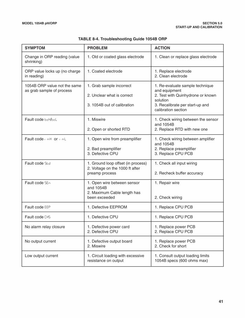
41
SYMPTOM PROBLEM ACTION
Change in ORP reading (value 1. Old or coated glass electrode 1. Clean or replace glass electrodeshrinking)
ORP value locks up (no charge 1. Coated electrode 1. Replace electrode in reading) 2. Clean electrode
1054B ORP value not the same 1. Grab sample incorrect 1. Re-evaluate sample technique as grab sample of process and equipment
2. Unclear what is correct 2. Test with Quinhydrone or known solution
3. 1054B out of calibration 3. Recalibrate per start-up andcalibration section
Fault code ���/�� 1. Miswire 1. Check wiring between the sensorand 1054B
2. Open or shorted RTD 2. Replace RTD with new one
Fault code � � � or � � 1. Open wire from preamplifier 1. Check wiring between amplifier and 1054B
2. Bad preamplifier 2. Replace preamplifier3. Defective CPU 3. Replace CPU PCB
Fault code ��� 1. Ground loop offset (in process) 1. Check all input wiring2. Voltage on the 1000 ft after preamp process 2. Recheck buffer accuracy
Fault code ��� 1. Open wire between sensor 1. Repair wireand 1054B 2. Maximum Cable length hasbeen exceeded 2. Check wiring
Fault code ��� 1. Defective EEPROM 1. Replace CPU PCB
Fault code ��� 1. Defective CPU 1. Replace CPU PCB
No alarm relay closure 1. Defective power card 1. Replace power PCB2. Defective CPU 2. Replace CPU PCB
No output current 1. Defective output board 1. Replace power PCB2. Miswire 2. Check for short
Low output current 1. Circuit loading with excessive 1. Consult output loading limits resistance on output 1054B specs (600 ohms max)
MODEL 1054B pH/ORP SECTION 5.0START-UP AND CALIBRATION
TABLE 8-4. Troubleshooting Guide 1054B ORP

42
MODEL 1054B pH/ORP SECTION 8.0DIAGNOSTICS AND TROUBLESHOOTING
8.2 TROUBLESHOOTING. The Model 1054BAnalyzer is designed with state-of-the-art micro-processor circuitry, making troubleshooting simple anddirect. Subassembly replacement, i.e. printed circuitboard replacement, is all that is usually required.
8.2.1 Installation Failure. If failure does occur, com-plete the following steps:
1. Check for a fault flag. If a fault condition exists,refer to Table 8-1 for the fault mnemonic explana-tion.
2. Check wiring connections for proper installation.
3. Refer to Troubleshooting Table 8-3 (pH) or Table8-4 (ORP). The table is arranged with the mostcommon problems listed first.
8.2.2 LCD/LED Display Test. Display Mnemonic ���.Selecting this option will activate all the display seg-ments. This item is used if a faulty display is suspect-ed. Refer to Figure 3-1.
1. Enter Set Mode by pressing ACCESS key twice.
2. SCROLL (�) until ��� appears on the display.
3. SELECT.
8.2.3 Software Version. Display Mnemonic ���.Selection of this item will display the software revisionlevel of the CPU. This number may be requested byfactory service personnel i f troubleshooting isrequired.
1. Enter Set Mode by pressing ACCESS key twice.
2. SCROLL (�) until ��� appears on the display.
3. SELECT. (i.e., 2.0.6 displayed.)
8.2.4 Sensor Troubleshooting. In addition to thefault mnemonics that relate to a possible sensor prob-lem (Tables 8-1 and 8-3), the 1054B pH can displaythe input in millivolts generated from the sensor. SeeTable 8-5 for how the millivolt input relates to pH. Ifthe analyzer values do not agree within about 40 to60 mV of those in the table, the analyzer has beenincorrectly standardized for pH, the reference may besignificantly poisoned, or some other significant prob-lem exists. To read the millivolt input, go to Section8.2.5.
For an additional diagnostics tool you can look at the��� impedance value as described in Section 4.6.
8.2.5 Electrode Input (1054B pH). Display Mnemonic���. When selected, the analyzer displays the millivoltinput from the sensor. The displayed value is not tem-perature corrected.
1. Press the ACCESS key twice. ��� will briefly dis-play followed by ���. Not required if already in setmenu.
2. SELECT this item to read the mV input.
3. Press the PV key to return to normal operation.
8.2.6 CPU Board Replacement. If there is a problemwith the CPU board resulting in its replacement, spe-cific procedures (included with the order) for calibrat-ing the new board must be followed exactly or themicroprocessor will be improperly programmed.Should this occur, it will be necessary to return theanalyzer to the factory for reprogramming.
8.2.7 Power Board Replacement. If it becomes nec-essary to replace the power board, the CPU board willneed to be recalibrated following specific proceduresthat are included with the power board. Failure to fol-low these procedures exactly will cause the micro-processor to be improperly programmed and requirethe return of the analyzer to the factory for reprogram-ming.
8.3 INSTRUMENT MAINTENANCE. To maintain theappearance and extend the life of the enclosure, itshould be cleaned on a regular basis using a mildsoap and water solution followed by a clean waterrinse.
Input to AnalyzerpH in Millivolts
15°C (59°F) 25°C (77°F) 50°C (122°F) 80°C (176°F)
0 396 410 444 4861 340 351 381 4162 283 293 317 3473 226 234 254 2774 170 176 190 2085 113.2 117.1 127.0 138.76 56.6 58.6 63.5 69.47 0 0 0 08 – 56.6 – 58.6 – 63.5 – 69.49 – 113.2 – 117.1 – 127.0 – 138.7
10 – 170 – 176 – 190 – 20811 – 226 – 234 – 254 – 27712 – 283 – 293 – 317 – 34713 – 340 – 351 – 381 – 41614 – 396 – 410 – 444 – 486
TABLE 8-5Sensor Input to Analyzer Verses
pH at Four Temperatures*
* These values do not apply for non-glass electrodes.

43
MODEL 1054B pH/ORP SECTION 8.0DIAGNOSTICS AND TROUBLESHOOTING
P/N DESCRIPTION22966-00 PCB, LCD Digital Display23025-01 Panel Mounting Kit23739-00 PCB Power Supply23245-01 PCB, LED Digital Display23740-00 PCB, Motherboard23695-00 Keyboard Overlay, LCD Version, pH23695-01 Keyboard Overlay, LED Version, pH23665-00 PCB, CPU, pH, with electrode diagnostics33469-00 Enclosure Body33470-00 Enclosure, Rear Cover32937-00 Gasket, Rear Cover32938-00 Gasket, Panel9100157 Fuse, .10A 250V, 3AB, Slo-Blow9100160 Fuse, .250A 125V9100189 Fuse, .750A 125V
P/N DESCRIPTION2001492 Stainless Steel Tag23053-00 Mounting Bracket, 2-inch Pipe23054-01 Mounting Bracket, Wall, with Junction box23268-01 Heater, 115 VAC, 50/60 Hz, 1054B
(Code 20 Only)23268-02 Heater, 230 VAC, 50/60 Hz, 1054B
(Code 20 Only)23363-00 Preamplifier, Pt 100 23508-00 Preamplifier, Integral Pt100,
For Wall Mount Enclosure
TABLE 8-8. Ordering Information
The Model 1054B Microprocessor Analyzer: Housed in a corrosion resistant, weatherproof enclosure and oper-ates on either 115 or 230 VAC, 50/60 Hz power. Standard features include digital display, isolated current output,dual alarms, and automatic or manual temperature compensation.
Model Description1054B Microprocessor Analyzer (3.5 lb/1.5kg)
Code MeasurementpH pH
ORP Oxidation Reduction Potential
Code Display01 LCD Display02 LED Display
Code Options20 Wall Mount Enclosure
RECOMMENDED SENSORS FOR ORP:Model 300 Retractable Model 330B Flow Through Model 381 Insertion/Submersion/Flow
Model 385 Retractable Models 389/399 Disposable Model 396P TUpH Disposable Model 396R TUpH Retractable
RECOMMENDED SENSORS FOR pH:Model 300 Retractable Model 320B Flow ThroughModel 320HP High PurityModel 328A Steam Sterilizable Model 371 EuroSenz Model 381 Insertion/Submersion/Flow Model 385 Retractable Models 389/399 Disposable Models 396/396P TUpH DisposableModel 396R TUpH RetractableModel 397 Quik-Loc
TABLE 8-6. Replacement Parts TABLE 8-7. Accessories

44
MODEL 1054B pH/ORP SECTION 9.0RETURN OF MATERIALS
SECTION 9.0RETURN OF MATERIALS
9.1 GENERAL. To expedite the repair and return ofinstruments, proper communication between the cus-tomer and the factory is important. A return materialauthorization number is required. Call (949) 757-8500.The Return of Materials Request form is provided foryou to copy and use in case the situation arises. Theaccuracy and completeness of this form will affect theprocessing time of your materials.
9.2 WARRANTY REPAIR. The following is the proce-dure for returning products still under warranty.
1. Contact the factory for authorization.
2. Complete a copy of the Return of MaterialsRequest form as completely and accurately aspossible.
3. To verify warranty, supply the factory sales ordernumber or the original purchase order number. Inthe case of individual parts or sub-assemblies, theserial number on the mother unit must be sup-plied.
4. Carefully package the materials and enclose yourLetter of Transmittal and the completed copy ofthe Return of Materials Request form. If possible,pack the materials in the same manner as it wasreceived.
IMPORTANTPlease see second section of Return ofMaterials Request Form. Compliance tothe OSHA requirements is mandatory forthe safety of all personnel. MSDS formsand a certification that the instrumentshave been disinfected or detoxified arerequired.
5. Send the package prepaid to:
Rosemount Analytical Inc.2400 Barranca ParkwayIrvine, CA 92606
Attn: Factory Repair
Mark the package:
Returned for Repair RMA No. _______________
Model No. ______________
9.3 NON WARRANTY REPAIR.
1. Contact the factory for authorization.
2. Fill out a copy of the Return of Materials Requestform as completely and accurately as possible.
3. Include a purchase order number and make sureto include the name and telephone number of theright individual to be contacted should additionalinformation be needed.
4. Do Steps 4 and 5 of Section 9.2.
NOTEConsult the factory for additional infor-mation regarding service or repair.

WARRANTYSeller warrants that the firmware will execute the programming instructions provided by Seller, and that the Goods manufacturedor Services provided by Seller will be free from defects in materials or workmanship under normal use and care until the expira-tion of the applicable warranty period. Goods are warranted for twelve (12) months from the date of initial installation or eighteen(18) months from the date of shipment by Seller, whichever period expires first. Consumables, such as glass electrodes,membranes, liquid junctions, electrolyte, o-rings, catalytic beads, etc., and Services are warranted for a period of 90days from the date of shipment or provision. Products purchased by Seller from a third party for resale to Buyer ("Resale Products") shall carry only the warranty extended bythe original manufacturer. Buyer agrees that Seller has no liability for Resale Products beyond making a reasonable commercialeffort to arrange for procurement and shipping of the Resale Products. If Buyer discovers any warranty defects and notifies Seller thereof in writing during the applicable warranty period, Seller shall, atits option, promptly correct any errors that are found by Seller in the firmware or Services, or repair or replace F.O.B. point of man-ufacture that portion of the Goods or firmware found by Seller to be defective, or refund the purchase price of the defective por-tion of the Goods/Services. All replacements or repairs necessitated by inadequate maintenance, normal wear and usage, unsuitable power sources, unsuit-able environmental conditions, accident, misuse, improper installation, modification, repair, storage or handling, or any othercause not the fault of Seller are not covered by this limited warranty, and shall be at Buyer's expense. Seller shall not be obligat-ed to pay any costs or charges incurred by Buyer or any other party except as may be agreed upon in writing in advance by anauthorized Seller representative. All costs of dismantling, reinstallation and freight and the time and expenses of Seller's person-nel for site travel and diagnosis under this warranty clause shall be borne by Buyer unless accepted in writing by Seller. Goods repaired and parts replaced during the warranty period shall be in warranty for the remainder of the original warranty peri-od or ninety (90) days, whichever is longer. This limited warranty is the only warranty made by Seller and can be amended onlyin a writing signed by an authorized representative of Seller. Except as otherwise expressly provided in the Agreement, THEREARE NO REPRESENTATIONS OR WARRANTIES OF ANY KIND, EXPRESS OR IMPLIED, AS TO MERCHANTABILITY, FIT-NESS FOR PARTICULAR PURPOSE, OR ANY OTHER MATTER WITH RESPECT TO ANY OF THE GOODS OR SERVICES.
RETURN OF MATERIAL
Material returned for repair, whether in or out of warranty, should be shipped prepaid to:
Emerson Process ManagementLiquid Division
2400 Barranca ParkwayIrvine, CA 92606
The shipping container should be marked:Return for RepairModel _______________________________
The returned material should be accompanied by a letter of transmittal which should include the following information (make acopy of the "Return of Materials Request" found on the last page of the Manual and provide the following thereon):
1. Location type of service, and length of time of service of the device.2. Description of the faulty operation of the device and the circumstances of the failure.3. Name and telephone number of the person to contact if there are questions about the returned material.4. Statement as to whether warranty or non-warranty service is requested.5. Complete shipping instructions for return of the material.
Adherence to these procedures will expedite handling of the returned material and will prevent unnecessary additional chargesfor inspection and testing to determine the problem with the device.
If the material is returned for out-of-warranty repairs, a purchase order for repairs should be enclosed.

Credit Cards for U.S. Purchases Only.
The right people,the right answers,right now.
ON-LINE ORDERING NOW AVAILABLE ON OUR WEB SITEhttp://www.raihome.com
Emerson Process ManagementLiquid Division2400 Barranca ParkwayIrvine, CA 92606 USATel: (949) 757-8500Fax: (949) 474-7250
http://www.raihome.com
© Rosemount Analytical Inc. 2003