microfluidics (colin/microfluidics) || fluidic microsystems
TRANSCRIPT
Chapter 8
Fluidic Microsystems
8.1. Introduction
The development of microsystems has led to a considerable advancement in the field of microfluidic systems. Indeed, the miniaturization of existing fluidic systems presents many advantages in terms of reactive product consumption, analysis time and energy consumption. Thus, the industries of valves, medical pumps and flow sensors have found a means of providing more powerful and effective products in microtechnologies.
This chapter is structured in the following way: after a presentation of the various basic modules used in fluidic microsystems, many real-world examples are presented in order to show the performance of various existing systems.
8.2. Basic modules
Microfluidic systems can generally be broken down into several elements, each having a very precise function. The principal basic elements are the following:
– microchannels, which are used to connect various elements;
– microdiodes, which are elements of fixed geometry, the properties of which depend on the flow direction;
Chapter written by Isabelle DUFOUR and Olivier FRANÇAIS.
Microfluidics Edited by Stéphane Colin © 2010 ISTE Ltd. Published 2010 by ISTE Ltd.
350 Microfluidics
– microvalves, which are elements with moving parts whose function is to prevent or control the fluid flow;
– micropumps, which are used to move the fluid.
After presenting the principles governing the various physical or physicochemical means of actuating a fluid (section 8.2.1), the various elementary functions encountered in fluid microsystems are listed (section 8.2.2). To conclude this part, we show how these various basic elements can be modeled and present methods used for the global simulation of microfluidic systems (section 8.2.3).
8.2.1. Different actuators
Fluid actuation, i.e. the generation of movements or the variation of pressure, may be done in two different ways:
– by deflecting or deforming a solid material that is in contact with the fluid that we wish to actuate;
– by using forces that act directly on the fluid without deforming an intermediate structure.
8.2.1.1. Indirect action on fluid via a solid material deformation
The deformation of a solid can be obtained due to the particular properties of a material (referred to as an “active material”) or by an external action on this deformable solid.
The physical principles generally used in these two types of actuation are detailed in what follows. The deformations of beams or membranes are chosen as illustrative examples because, as we shall see with examples of real systems, these two mechanical structures are found in many microfluidic systems.
8.2.1.1.1. Active material deformation
In microfluidic systems, there are primarily three types of active materials that are used: piezoelectric materials (such as PZT or AlN), magnetostrictive materials (such as TbFe, TbDyFe or TbCo) or shape memory alloys (TiNi, for example):
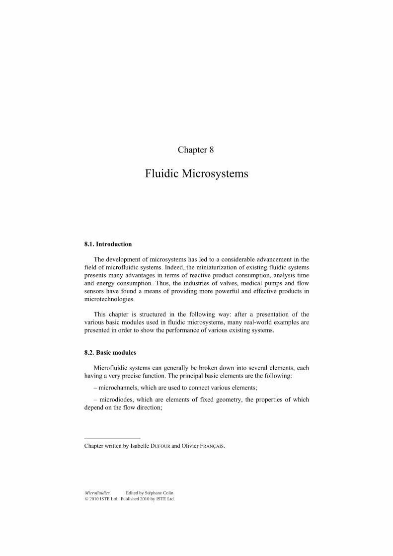
– Piezoelectricity [IKE 90] is the property possessed by certain materials that electrically polarize under mechanical pressure (direct effect) and are deformed in the presence of an electric polarization (opposite effect). For actuation, it is the opposite effect that is used. The piezoelectric actuation of a microstructure may be created by applying an electrical potential difference to a piezoelectric material deposited onto the structure: the contraction of the piezoelectric layer then causes the structure to bend due to the bilayer effect (see Figure 8.1).
Fluidic Microsystems 351
U contraction
Figure 8.1. Principle of piezoelectric actuation
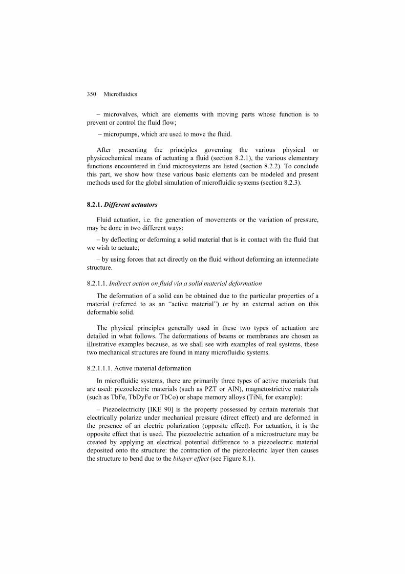
– Magnetostriction [HAR 99] is similar to piezoelectricity but in this case the mechanical deformation is induced by the presence of a magnetic field. The structures of magnetostrictive actuators are thus comparable to those of piezoelectric actuators, except the active material differs (see Figure 8.2). Of particular interest with this type of actuation is that it can be controlled remotely (in this case the excitation can be external to the microsystem).
Bcontraction
Figure 8.2. Principle of magnetostrictive actuation
– Shape-memory alloys [PAT 90] can undergo recoverable deformations more than 100 times higher than typical metals. After treatment, these materials memorize two geometrical forms, passing from one to the other by simple heating or cooling: this occurs due to a phase transformation in the solid state known as “martensitic”. In microsystems, the rise in temperature, and thus the shape changes, are obtained by the Joule effect caused by circulating an electric current in the structure (see Figure 8.3). This transformation is almost instantaneous and takes place at a temperature dependant on the concentrations of the alloy materials.
Temperature T1 Temperature T2
Figure 8.3. Principle of a shape-memory alloy-based actuator
352 Microfluidics
8.2.1.1.2. Passive material deformation by external action
There are many ways to deform a material but we will limit our discussion to listing the phenomena most often employed in microfluidic systems:
– Pneumatic action: Intuitively the simplest way to deform a structure is to subject it to a pressure difference. This seemingly simple method is not easy to implement at the microsystem scale, however, because the traditional piston-type systems cannot be created in these dimensions using manufacturing processes derived from microelectronics. In microsystems, the difference in pressure necessary for structural deformation is not generated mechanically but rather thermally or electrochemically (see below).
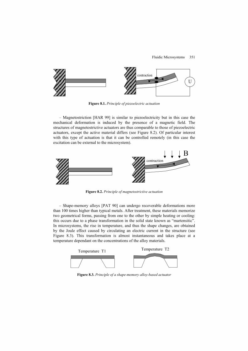
– Thermopneumatic action: This principle is based on increasing the temperature of a tight cavity that causes an overpressure, thus making it possible to deform the flexible wall of the cavity (see Figure 8.4). The rise in the temperature is generally obtained via a resistance traversed by an electric current (Joule effect). In microsystems, the surface-to-volume ratio is high; thus, heating of the structure requires a relatively large amount of energy compared to systems of usual size.
air I=0 air I
conductors
Figure 8.4. Principle of thermopneumatic actuation
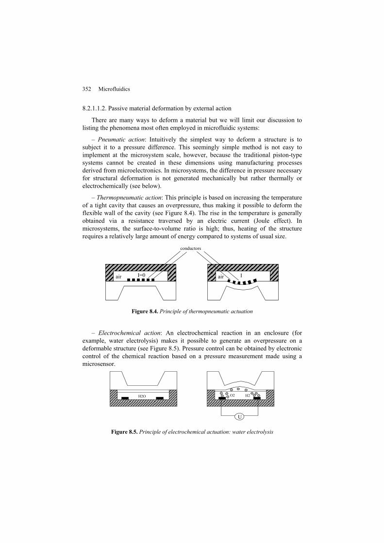
– Electrochemical action: An electrochemical reaction in an enclosure (for example, water electrolysis) makes it possible to generate an overpressure on a deformable structure (see Figure 8.5). Pressure control can be obtained by electronic control of the chemical reaction based on a pressure measurement made using a microsensor.
H2O
U
O2 H2
Figure 8.5. Principle of electrochemical actuation: water electrolysis
Fluidic Microsystems 353
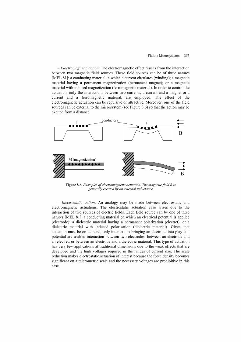
– Electromagnetic action: The electromagnetic effect results from the interaction between two magnetic field sources. These field sources can be of three natures [MEL 81]: a conducting material in which a current circulates (winding); a magnetic material having a permanent magnetization (permanent magnet); or a magnetic material with induced magnetization (ferromagnetic material). In order to control the actuation, only the interactions between two currents, a current and a magnet or a current and a ferromagnetic material, are employed. The effect of the electromagnetic actuation can be repulsive or attractive. Moreover, one of the field sources can be external to the microsystem (see Figure 8.6) so that the action may be excited from a distance.
I I
B
B
M (magnetization)
conductors
Figure 8.6. Examples of electromagnetic actuation. The magnetic field B is generally created by an external inductance
– Electrostatic action: An analogy may be made between electrostatic and electromagnetic actuations. The electrostatic actuation case arises due to the interaction of two sources of electric fields. Each field source can be one of three natures [MEL 81]: a conducting material on which an electrical potential is applied (electrode); a dielectric material having a permanent polarization (electret); or a dielectric material with induced polarization (dielectric material). Given that actuation must be on-demand, only interactions bringing an electrode into play at a potential are usable: interaction between two electrodes; between an electrode and an electret; or between an electrode and a dielectric material. This type of actuation has very few applications at traditional dimensions due to the weak effects that are developed and the high voltages required in the ranges of current size. The scale reduction makes electrostatic actuation of interest because the force density becomes significant on a micrometric scale and the necessary voltages are prohibitive in this case.
354 Microfluidics
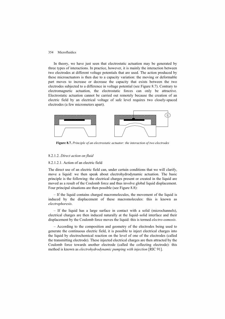
In theory, we have just seen that electrostatic actuation may be generated by three types of interactions. In practice, however, it is mainly the interaction between two electrodes at different voltage potentials that are used. The action produced by these microactuators is then due to a capacity variation: the moving or deformable part moves to increase or decrease the capacity that exists between the two electrodes subjected to a difference in voltage potential (see Figure 8.7). Contrary to electromagnetic actuation, the electrostatic forces can only be attractive. Electrostatic actuation cannot be carried out remotely because the creation of an electric field by an electrical voltage of safe level requires two closely-spaced electrodes (a few micrometers apart).
U
Figure 8.7. Principle of an electrostatic actuator: the interaction of two electrodes
8.2.1.2. Direct action on fluid
8.2.1.2.1. Action of an electric field
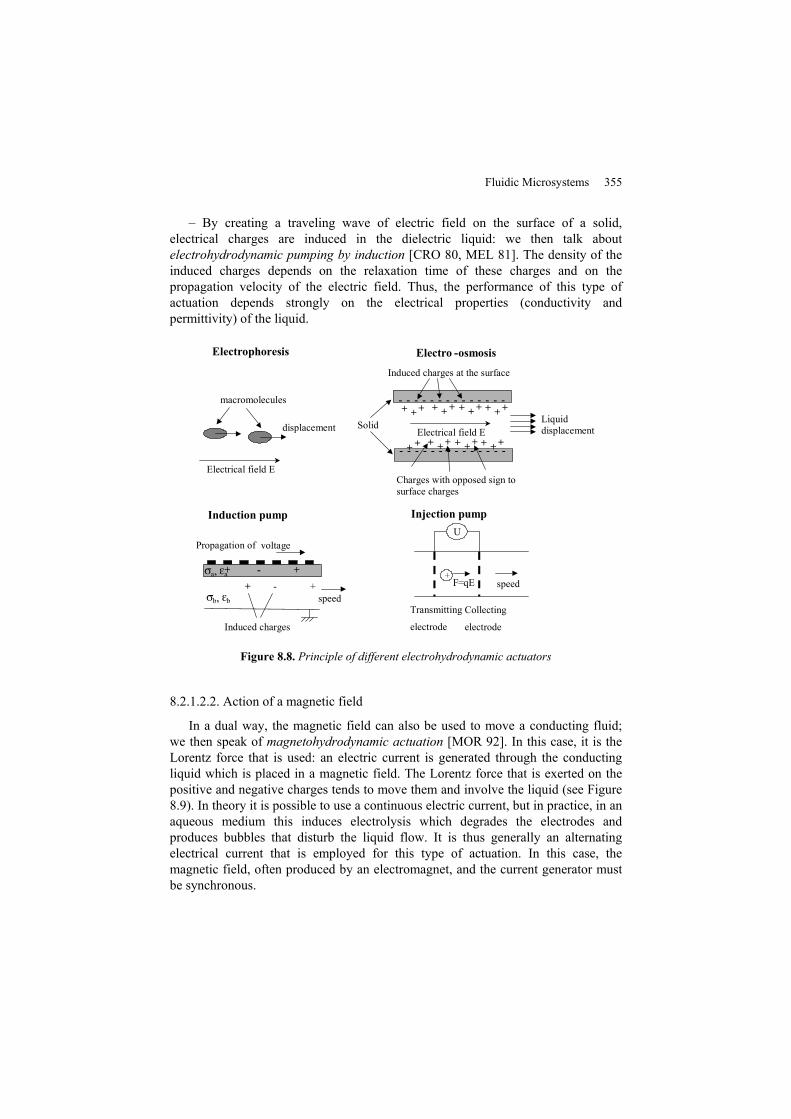
The direct use of an electric field can, under certain conditions that we will clarify, move a liquid: we then speak about electrohydrodynamic actuation. The basic principle is the following: the electrical charges present or created in the liquid are moved as a result of the Coulomb force and thus involve global liquid displacement. Four principal situations are then possible (see Figure 8.8):
– If the liquid contains charged macromolecules, the movement of the liquid is induced by the displacement of these macromolecules: this is known as electrophoresis.
– If the liquid has a large surface in contact with a solid (microchannels), electrical charges are then induced naturally at the liquid–solid interface and their displacement by the Coulomb force moves the liquid: this is termed electro-osmosis.
– According to the composition and geometry of the electrodes being used to generate the continuous electric field, it is possible to inject electrical charges into the liquid by electrochemical reaction on the level of one of the electrodes (called the transmitting electrode). These injected electrical charges are then attracted by the Coulomb force towards another electrode (called the collecting electrode): this method is known as electrohydrodynamic pumping with injection [RIC 91].
Fluidic Microsystems 355
– By creating a traveling wave of electric field on the surface of a solid, electrical charges are induced in the dielectric liquid: we then talk about electrohydrodynamic pumping by induction [CRO 80, MEL 81]. The density of the induced charges depends on the relaxation time of these charges and on the propagation velocity of the electric field. Thus, the performance of this type of actuation depends strongly on the electrical properties (conductivity and permittivity) of the liquid.
- - - - - - - - - - - - - -
- - - - - - - - - - - - - -
+ + + + + + + + + + + +
+ + + + + + + + + + +
Solid
Induced charges at the surface
Charges with opposed sign to isurface charges
Electrical field ELiquid displacement
Electrical field E
macromolecules displacement
U
Transmitting
electrode
Collecting
electrode
speed+
F=qEspeed
Induced charges
Propagation of h
voltage + - +
+ + - σ a , ε a σ b , ε b
Electrophoresis Electro -osmosis
Induction pump Injection pump
Figure 8.8. Principle of different electrohydrodynamic actuators
8.2.1.2.2. Action of a magnetic field
In a dual way, the magnetic field can also be used to move a conducting fluid; we then speak of magnetohydrodynamic actuation [MOR 92]. In this case, it is the Lorentz force that is used: an electric current is generated through the conducting liquid which is placed in a magnetic field. The Lorentz force that is exerted on the positive and negative charges tends to move them and involve the liquid (see Figure 8.9). In theory it is possible to use a continuous electric current, but in practice, in an aqueous medium this induces electrolysis which degrades the electrodes and produces bubbles that disturb the liquid flow. It is thus generally an alternating electrical current that is employed for this type of actuation. In this case, the magnetic field, often produced by an electromagnet, and the current generator must be synchronous.
356 Microfluidics
B I+- F
F
v
v
Figure 8.9. Principle of magnetohydrodynamic actuation
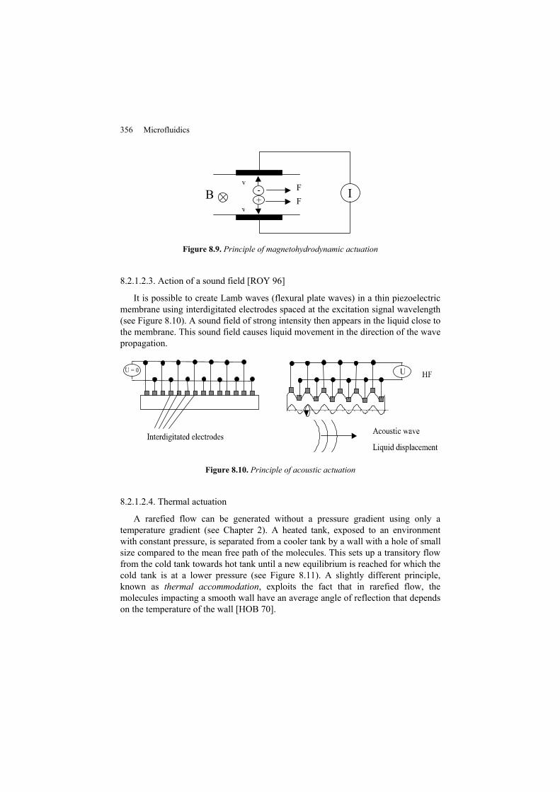
8.2.1.2.3. Action of a sound field [ROY 96]
It is possible to create Lamb waves (flexural plate waves) in a thin piezoelectric membrane using interdigitated electrodes spaced at the excitation signal wavelength (see Figure 8.10). A sound field of strong intensity then appears in the liquid close to the membrane. This sound field causes liquid movement in the direction of the wave propagation.
Figure 8.10. Principle of acoustic actuation
8.2.1.2.4. Thermal actuation
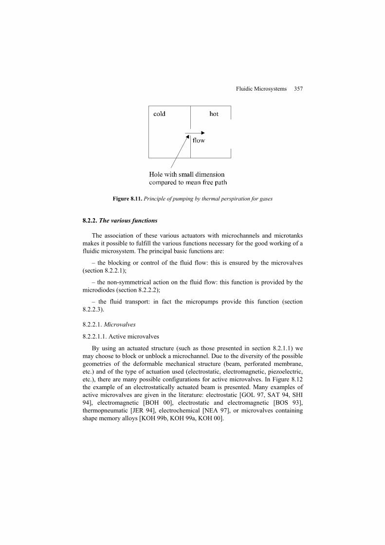
A rarefied flow can be generated without a pressure gradient using only a temperature gradient (see Chapter 2). A heated tank, exposed to an environment with constant pressure, is separated from a cooler tank by a wall with a hole of small size compared to the mean free path of the molecules. This sets up a transitory flow from the cold tank towards hot tank until a new equilibrium is reached for which the cold tank is at a lower pressure (see Figure 8.11). A slightly different principle, known as thermal accommodation, exploits the fact that in rarefied flow, the molecules impacting a smooth wall have an average angle of reflection that depends on the temperature of the wall [HOB 70].
Fluidic Microsystems 357
Figure 8.11. Principle of pumping by thermal perspiration for gases
8.2.2. The various functions
The association of these various actuators with microchannels and microtanks makes it possible to fulfill the various functions necessary for the good working of a fluidic microsystem. The principal basic functions are:
– the blocking or control of the fluid flow: this is ensured by the microvalves (section 8.2.2.1);
– the non-symmetrical action on the fluid flow: this function is provided by the microdiodes (section 8.2.2.2);
– the fluid transport: in fact the micropumps provide this function (section 8.2.2.3).
8.2.2.1. Microvalves
8.2.2.1.1. Active microvalves
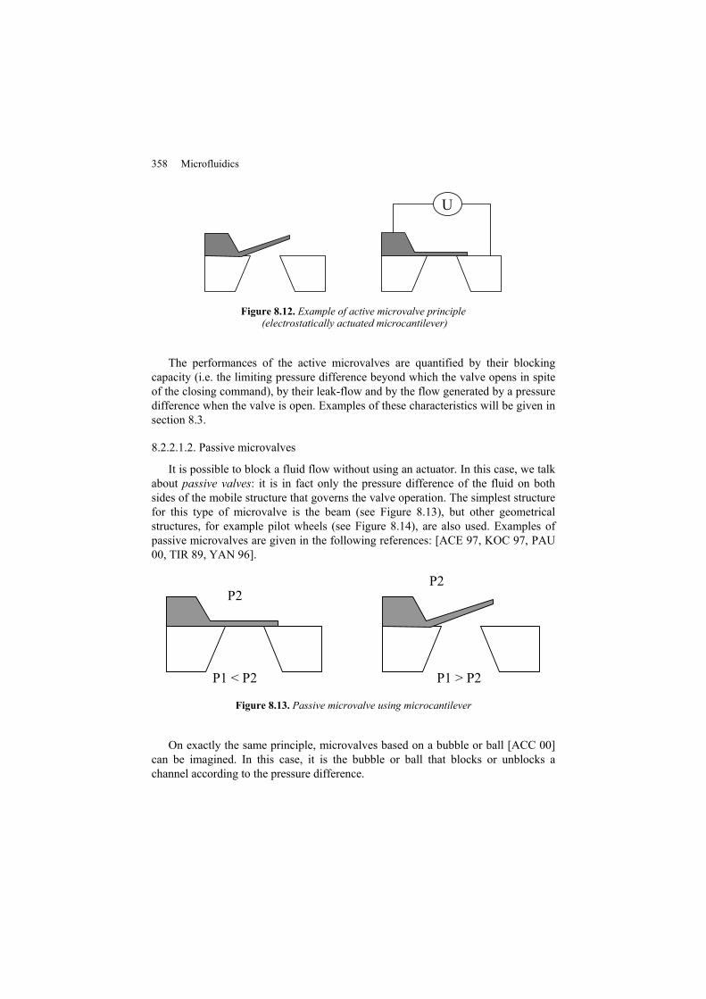
By using an actuated structure (such as those presented in section 8.2.1.1) we may choose to block or unblock a microchannel. Due to the diversity of the possible geometries of the deformable mechanical structure (beam, perforated membrane, etc.) and of the type of actuation used (electrostatic, electromagnetic, piezoelectric, etc.), there are many possible configurations for active microvalves. In Figure 8.12 the example of an electrostatically actuated beam is presented. Many examples of active microvalves are given in the literature: electrostatic [GOL 97, SAT 94, SHI 94], electromagnetic [BOH 00], electrostatic and electromagnetic [BOS 93], thermopneumatic [JER 94], electrochemical [NEA 97], or microvalves containing shape memory alloys [KOH 99b, KOH 99a, KOH 00].
358 Microfluidics
U
Figure 8.12. Example of active microvalve principle (electrostatically actuated microcantilever)
The performances of the active microvalves are quantified by their blocking capacity (i.e. the limiting pressure difference beyond which the valve opens in spite of the closing command), by their leak-flow and by the flow generated by a pressure difference when the valve is open. Examples of these characteristics will be given in section 8.3.
8.2.2.1.2. Passive microvalves
It is possible to block a fluid flow without using an actuator. In this case, we talk about passive valves: it is in fact only the pressure difference of the fluid on both sides of the mobile structure that governs the valve operation. The simplest structure for this type of microvalve is the beam (see Figure 8.13), but other geometrical structures, for example pilot wheels (see Figure 8.14), are also used. Examples of passive microvalves are given in the following references: [ACE 97, KOC 97, PAU 00, TIR 89, YAN 96].
P1 < P2 P1 > P2
P2P2
Figure 8.13. Passive microvalve using microcantilever
On exactly the same principle, microvalves based on a bubble or ball [ACC 00] can be imagined. In this case, it is the bubble or ball that blocks or unblocks a channel according to the pressure difference.
Fluidic Microsystems 359
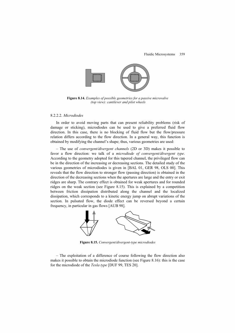
Figure 8.14. Examples of possible geometries for a passive microvalve (top view): cantilever and pilot wheels
8.2.2.2. Microdiodes
In order to avoid moving parts that can present reliability problems (risk of damage or sticking), microdiodes can be used to give a preferred fluid flow direction. In this case, there is no blocking of fluid flow but the flow/pressure relation differs according to the flow direction. In a general way, this function is obtained by modifying the channel’s shape; thus, various geometries are used:
– The use of convergent/divergent channels (2D or 3D) makes it possible to favor a flow direction: we talk of a microdiode of convergent/divergent type. According to the geometry adopted for this tapered channel, the privileged flow can be in the direction of the increasing or decreasing sections. The detailed study of the various geometries of microdiodes is given in [BAL 01, GER 98, OLS 00]. This reveals that the flow direction to stronger flow (passing direction) is obtained in the direction of the decreasing sections when the apertures are large and the entry or exit ridges are sharp. The contrary effect is obtained for weak apertures and for rounded ridges on the weak section (see Figure 8.15). This is explained by a competition between friction dissipation distributed along the channel and the localized dissipation, which corresponds to a kinetic energy jump on abrupt variations of the section. In pulsated flow, the diode effect can be reversed beyond a certain frequency, in particular in gas flows [AUB 98].
Figure 8.15. Convergent/divergent-type microdiodes
– The exploitation of a difference of course following the flow direction also makes it possible to obtain the microdiode function (see Figure 8.16): this is the case for the microdiode of the Tesla type [DUF 99, TES 20].

360 Microfluidics
Figure 8.16. Microdiode of Tesla type
– The use of a geometry making it possible to create a swirl for only one flow direction can also be used. It is this principle that is used in vortex type microdiodes (see Figure 8.17). After the fluid enters by the tangential channel of rectangular section, it undergoes a turbulent swirling in the chamber placed above the pyramidal exit channel. The pressure loss by kinetic energy dissipation that results from it is more important in this direction than in the other direction (entry by the pyramidal channel), where the fluid runs out in the diode chamber without whirling [AND 01].
Figure 8.17. Microdiode of vortex type
In the permanent mode, the microdiodes can be regarded as microvalves with a high leakage rate.
8.2.2.3. Micropumps
In microsystems, fluid transport is accomplished by micropumps. There are three types: micropumps with membranes, peristaltic micropumps and micropumps without a moving part.
8.2.2.3.1. Volumetric micropumps with membrane
In the case of volumetric membrane micropumps, fluid displacement is ensured by the deflection of a membrane and the direction of fluid displacement is managed
Fluidic Microsystems 361
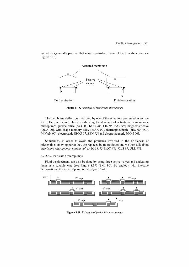
via valves (generally passive) that make it possible to control the flow direction (see Figure 8.18).
Figure 8.18. Principle of membrane micropumps
The membrane deflection is ensured by one of the actuations presented in section 8.2.1. Here are some references showing the diversity of actuations in membrane micropumps: piezoelectric [ACC 00, KOC 98a, LIN 98, PAR 99], magnetostrictive [QUA 00], with shape memory alloy [MAK 00], thermopneumatic [JEO 00, SCH 94,VAN 90], electrostatic [BOU 97, ZEN 95] and electromagnetic [GON 00].
Sometimes, in order to avoid the problems involved in the brittleness of microvalves (moving parts) they are replaced by microdiodes and we then talk about membrane micropumps without valves: [GER 95, KOC 98b, OLS 99, ULL 98].
8.2.2.3.2. Peristaltic micropumps
Fluid displacement can also be done by using three active valves and activating them in a suitable way (see Figure 8.19) [SMI 90]. By analogy with intestine deformations, this type of pump is called peristaltic.
entry
exit
2nd step
3rd step
1rst step
4th step
5th step
Figure 8.19. Principle of peristaltic micropumps
362 Microfluidics
8.2.2.3.3. Micropumps without moving parts
Liquid actuation is possible via electrohydrodynamic or magnetohydrodynamic actuation (section 8.2.1.2). Through their mode of action, these two actuations and acoustic actuation micropump liquid without the necessity of using microvalves or microdiodes. Examples of the creation of these types of pumps are given in the following references: electrohydrodynamic micropumps [AHN 98, FUH 94,RIC 91], magnetohydrodynamic micropumps [JAN 00, LEM 00], acoustic micropumps [NGU 99].
In the same way, the movement of a gas can be produced directly by thermal action (section 8.2.1.2). Examples of studies and achievements of prototypes of vacuum pumps using this principle are given in the following references: [HOB 00, YOU 99].
8.2.3. Study methodology
The complexity of the study of microfluidic microsystems is due to the fact that various fields of physics interact and must therefore be taken into account: solid mechanics, fluid mechanics and the physical phenomena used for actuation (piezoelectricity, electromagnetism, acoustics, etc.). To manage the interaction between these various fields for the whole microsystem is often difficult. Modeling and simulation then proceed generally in two stages: first modeling or simulation of basic modules and then simulation of the total system. We thus find the steps used for the modeling of automatisms with a fluid, in the case of microsystems, has characteristics related to containment.
The basic modules (microdiodes, microvalves, etc.) can be modeled either analytically or with simulations using numerical codes (for example finite elements, finite differences). An example of simulation of a microdiode by finite elements is presented Figure 8.20. Analytical modeling seems to be most relevant because it makes it possible to characterize the influence of each system parameter well. An undeniable advantage is that it makes it possible to understand the module operation and to determine the dimension of some of its elements. It should be noticed, however, that a complete analytical model is usually very difficult to obtain. The complexity of the analytical model can be naturally reduced because often one physical phenomenon dominates the others, thus leading to simplifying assumptions. Simulations by numerical calculation make it possible to solve more complicated cases, provided that the software used takes into account couplings between the various physical fields (fluid mechanics, solid mechanics, thermics, electromagnetism, etc.), or that the various pieces of application software used are coupled [BAL 01]. It should be noted however that the use of such software does not lead to a model but to a simulation, i.e. for a fixed geometry and materials, it is

Fluidic Microsystems 363
possible to know the operation of the simulated module. To obtain a behavioral law, it is necessary to carry out multiple simulations that thus require much more computing time.
Figure 8.20. Example of simulation by finite elements of a Tesla-type microdiode (simulation Comsol© – Visualization of the speed field)
With regards to the global microsystem simulation (comprising for example channels, valves, actuators, etc.), the use of a simulation program with distributed parameters becomes virtually impossible because of the complexity of the structure and thus of the associated grid. Several types of approaches are then used:
– The numerical resolution of the differential equations governing the microsystem operation. This is the approach adopted in [ZEN 94]. Still, the limitation of this approach lies in the complexity of the system.
– The use of bond graphs makes it possible to model the system starting from the relations representing the energy exchanges between the various parts of the system. This type of simulation was employed to determine the behavior of a thermopneumatic membrane micropump [VAN 90].
Mechanical or hydraulic parameters Electrical parameters
Flow Current
Pressure Voltage
Mass/S2 Inductance
Friction coefficient/S2 Resistance
Volume/compressibility coefficient Capacitance
Table 8.1. Example of simulation by finite elements of a Tesla-type microdiode (simulation Comsol © - Visualization of the speed field)
364 Microfluidics
Pe Ps
Pa
P
Pe Ps
Pa
P
Figure 8.21. Example of an equivalent electric diagram of a micropump
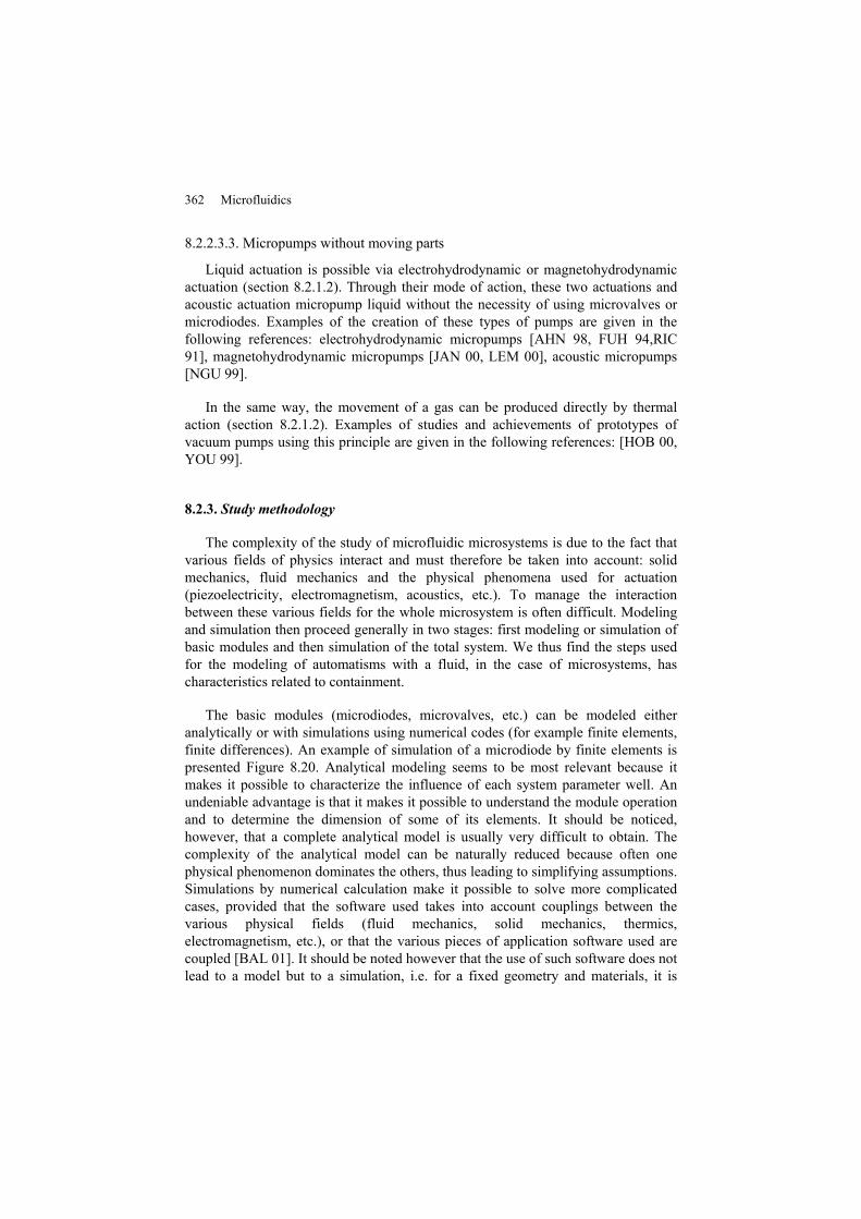
– The use of hydraulic/mechanical/electric analogies (see Table 8.1) makes it possible to simulate a complete microsystem (including its electronics) using the traditional simulator of an electrical circuit. This type of simulation in particular was used to simulate micropumps [BOU 96]. An example of an equivalent electrical diagram of a micropump is presented in Figure 8.21.
– Modeling basic modules can be used directly in simulations of type VHDL-AMS (very high speed integrated circuit hardware description language – analog and mixed systems), which makes it possible to simulate a complete system (including electronics) where different fields of physics interact (electromagnetism, solid mechanics, fluid mechanics, thermics, etc.). This type of simulation is very powerful but it should be recalled that the relevance of the results depends on the capacities of the models employed to give an account of the real behavior of the basic modules. In particular, this type of simulation was employed in [CAR 99, VOI 98].
Fluidic Microsystems 365
8.3. Examples of developments around microsystems
The goal of this section is to present a non-exhaustive list of developments created around microfluidic systems to highlight the variety which characterizes them.
8.3.1. Microchannels
The creation of microchannels has several applications. The first one is naturally to be integrated in a more complete system, such as a micropump, and to serve as a guide to bring the fluid to the pumping chamber. In this case, the flow in the channel is independent from the fluid direction.
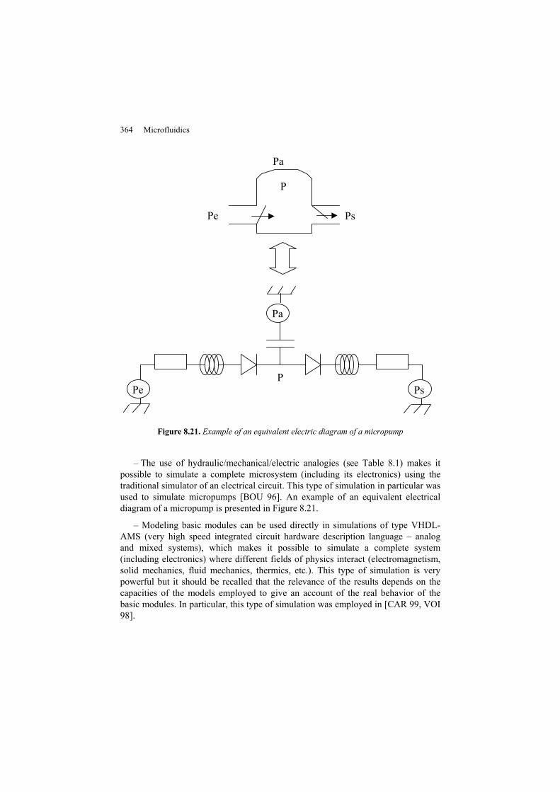
The design of a microchannel is not solely so that it can be used as a guide. In order to obtain a diffraction grid, a parallel microchannel network can be used. By controlling the liquid in the network, characteristics of the diffraction grid can be modified [SCH 98]. This grid acts as a reconfigurable diffraction network to modify the transmission properties of the overall structure by changing the refractive index between the liquid contents in the microchannels and the complete structure. Microchannels are obtained by using structured PDMS (polydimethylsiloxan) bonded on a glass wafer. Figure 8.22 presents the device. In this case, the network consists of 20 parallel channels 25 mm long, 20 µm deep and 50 µm wide. The channels are separated by 50 µm.
Figure 8.22. Global view of a diffraction network based on microchannels [SCH 98]
366 Microfluidics
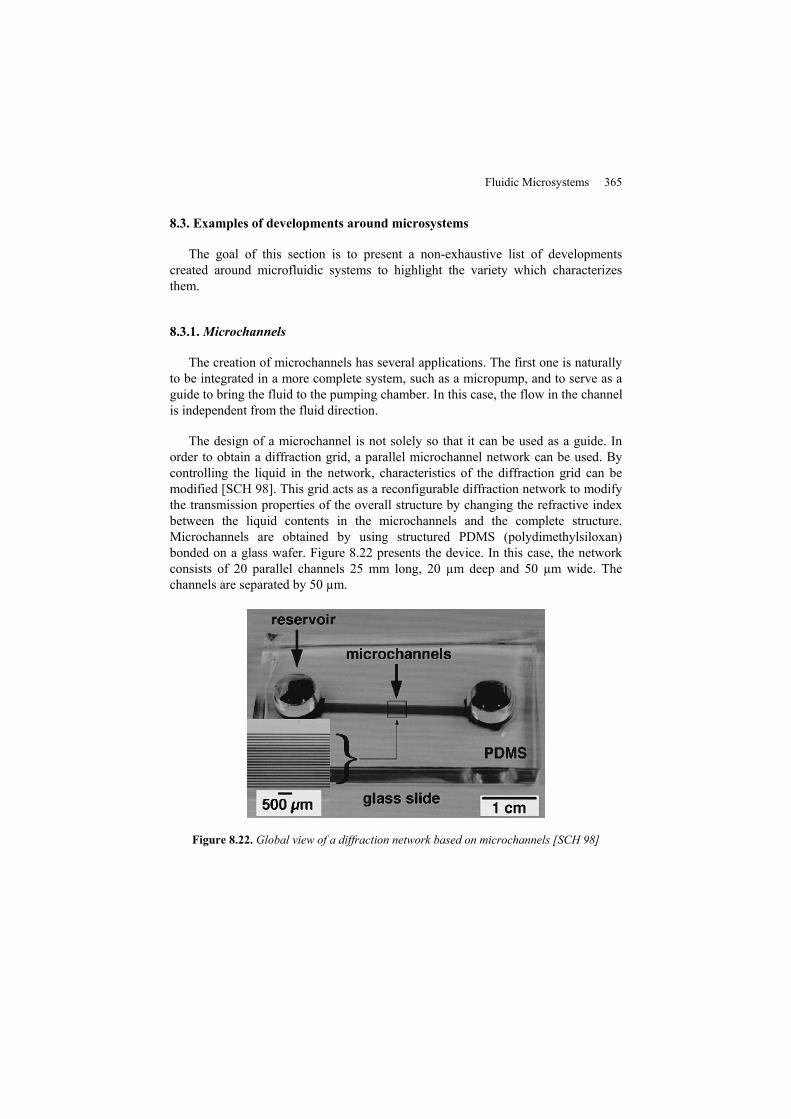
Miniaturized medical analysis devices enable us to reduce significantly the duration of analysis. This is the case for separative methods, such as electrophoresis (protein analysis, DNA sequencing). The speed of analysis can be increased by a factor of 100 compared to conventional methods. Based on microchannel [BEC 98] and avoiding gel filling, a separative device has been developed.
The first separation is performed using a channel 16 mm in length with a section 80 µm by 3-7 µm. The second separation is done using a network of 500 channels 5 mm long, 900 nm wide and 3-6 µm deep (see Figure 8.23). This network creates size selectivity and is perpendicular to the first channel separation. These channels are made on quartz wafer by RIE (reactive ionic etching) etching to get good profiles. The channel closure uses an anodic bonding and a cleaning process with NaOH to ensure a good sealing. The chip uses a classic potential of separation (2 kV) and occupies a surface of 23 mm x 23 mm.
Figure 8.23. Expansion of the area between the first channel separation perpendicular to the second network separation [BEC 98]
In order to reduce the analysis cost of a product requiring a reagent element, reduction of the mixture zone allows us to limit the quantity of reagent. So by using connected channels of micrometric size [VEE 99], not only is the quantity of reagent reduced but also the mixture time between product and reagent.
At these dimensions, flows are laminar. Mixtures are obtained by diffusion whose characteristic time is proportional to the square of diffusion length. A compromise is to be found between the diffusion time that decreases with the dimensions, and the losses of pressure, which increases. An example of real system
Fluidic Microsystems 367
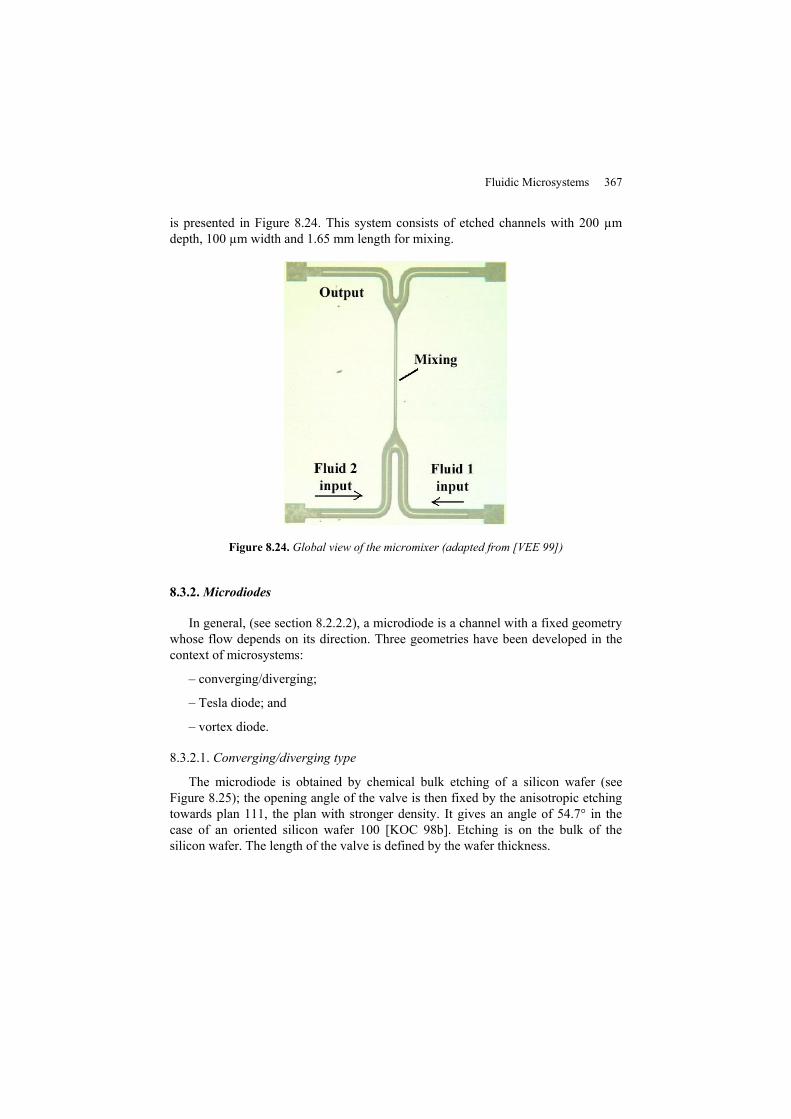
is presented in Figure 8.24. This system consists of etched channels with 200 µm depth, 100 µm width and 1.65 mm length for mixing.
Figure 8.24. Global view of the micromixer (adapted from [VEE 99])
8.3.2. Microdiodes
In general, (see section 8.2.2.2), a microdiode is a channel with a fixed geometry whose flow depends on its direction. Three geometries have been developed in the context of microsystems:
– converging/diverging;
– Tesla diode; and
– vortex diode.
8.3.2.1. Converging/diverging type
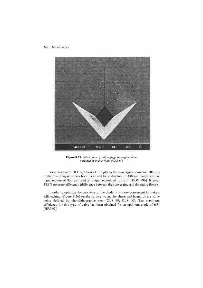
The microdiode is obtained by chemical bulk etching of a silicon wafer (see Figure 8.25); the opening angle of the valve is then fixed by the anisotropic etching towards plan 111, the plan with stronger density. It gives an angle of 54.7° in the case of an oriented silicon wafer 100 [KOC 98b]. Etching is on the bulk of the silicon wafer. The length of the valve is defined by the wafer thickness.
368 Microfluidics
Figure 8.25. Fabrication of a diverging/converging diode obtained by bulk etching [CNR 99]
For a pressure of 50 kPa, a flow of 133 µl/s in the converging sense and 108 µl/s in the diverging sense has been measured for a structure of 480 µm length with an input section of 850 µm² and an output section of 130 µm² [KOC 98b]. It gives 18.8% pressure efficiency (difference between the converging and diverging flows).
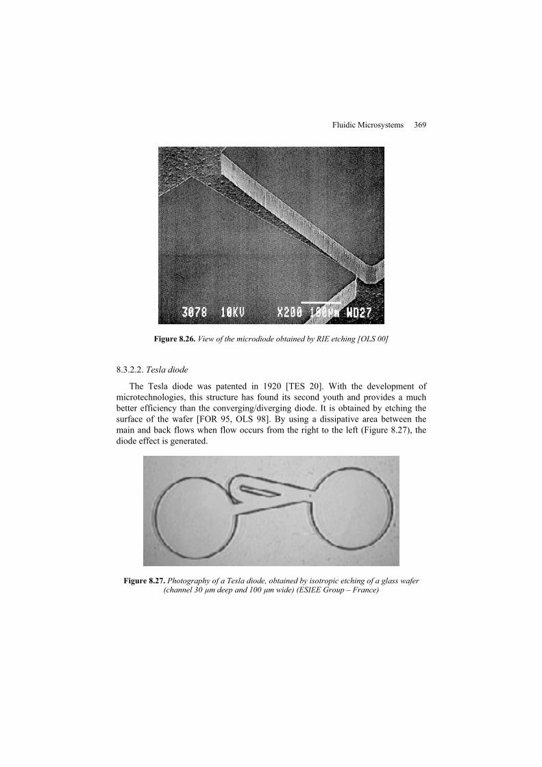
In order to optimize the geometry of the diode, it is more convenient to make a RIE etching (Figure 8.26) on the surface wafer, the shape and length of the valve being defined by photolithographic step [OLS 99, OLS 00]. The maximum efficiency for this type of valve has been obtained for an optimum angle of 6.3° [HES 97].
Fluidic Microsystems 369
Figure 8.26. View of the microdiode obtained by RIE etching [OLS 00]
8.3.2.2. Tesla diode
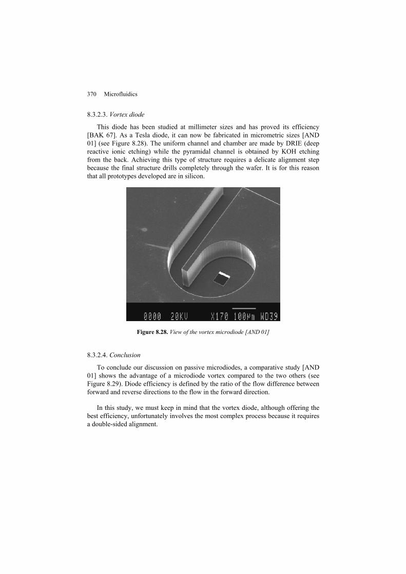
The Tesla diode was patented in 1920 [TES 20]. With the development of microtechnologies, this structure has found its second youth and provides a much better efficiency than the converging/diverging diode. It is obtained by etching the surface of the wafer [FOR 95, OLS 98]. By using a dissipative area between the main and back flows when flow occurs from the right to the left (Figure 8.27), the diode effect is generated.
Figure 8.27. Photography of a Tesla diode, obtained by isotropic etching of a glass wafer (channel 30 µm deep and 100 µm wide) (ESIEE Group – France)
370 Microfluidics
8.3.2.3. Vortex diode
This diode has been studied at millimeter sizes and has proved its efficiency [BAK 67]. As a Tesla diode, it can now be fabricated in micrometric sizes [AND 01] (see Figure 8.28). The uniform channel and chamber are made by DRIE (deep reactive ionic etching) while the pyramidal channel is obtained by KOH etching from the back. Achieving this type of structure requires a delicate alignment step because the final structure drills completely through the wafer. It is for this reason that all prototypes developed are in silicon.
Figure 8.28. View of the vortex microdiode [AND 01]
8.3.2.4. Conclusion
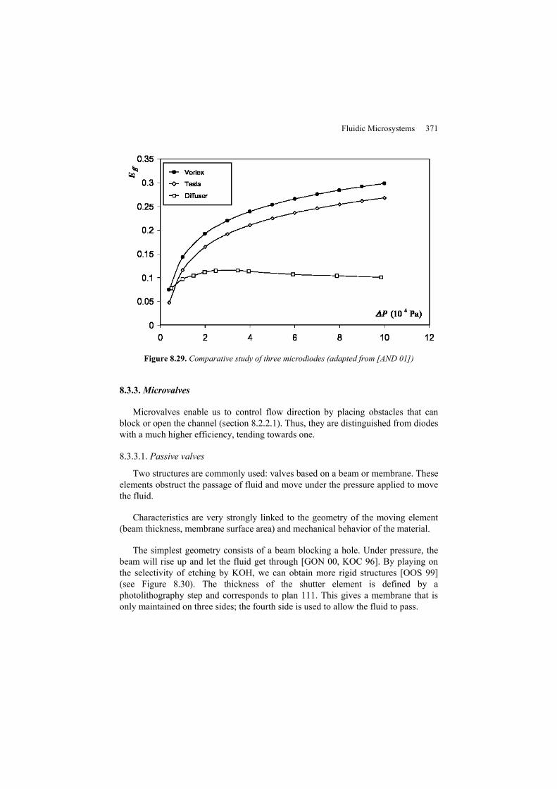
To conclude our discussion on passive microdiodes, a comparative study [AND 01] shows the advantage of a microdiode vortex compared to the two others (see Figure 8.29). Diode efficiency is defined by the ratio of the flow difference between forward and reverse directions to the flow in the forward direction.
In this study, we must keep in mind that the vortex diode, although offering the best efficiency, unfortunately involves the most complex process because it requires a double-sided alignment.
Fluidic Microsystems 371
Figure 8.29. Comparative study of three microdiodes (adapted from [AND 01])
8.3.3. Microvalves
Microvalves enable us to control flow direction by placing obstacles that can block or open the channel (section 8.2.2.1). Thus, they are distinguished from diodes with a much higher efficiency, tending towards one.
8.3.3.1. Passive valves
Two structures are commonly used: valves based on a beam or membrane. These elements obstruct the passage of fluid and move under the pressure applied to move the fluid.
Characteristics are very strongly linked to the geometry of the moving element (beam thickness, membrane surface area) and mechanical behavior of the material.
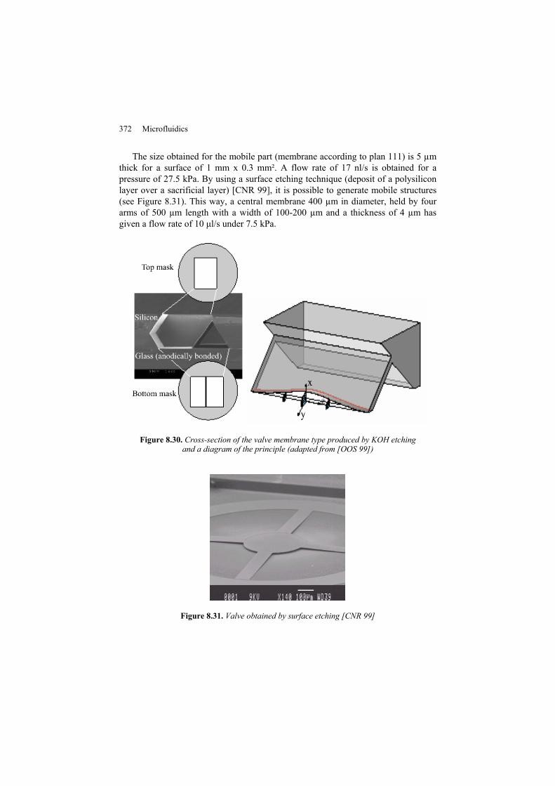
The simplest geometry consists of a beam blocking a hole. Under pressure, the beam will rise up and let the fluid get through [GON 00, KOC 96]. By playing on the selectivity of etching by KOH, we can obtain more rigid structures [OOS 99] (see Figure 8.30). The thickness of the shutter element is defined by a photolithography step and corresponds to plan 111. This gives a membrane that is only maintained on three sides; the fourth side is used to allow the fluid to pass.
372 Microfluidics
The size obtained for the mobile part (membrane according to plan 111) is 5 µm thick for a surface of 1 mm x 0.3 mm². A flow rate of 17 nl/s is obtained for a pressure of 27.5 kPa. By using a surface etching technique (deposit of a polysilicon layer over a sacrificial layer) [CNR 99], it is possible to generate mobile structures (see Figure 8.31). This way, a central membrane 400 µm in diameter, held by four arms of 500 µm length with a width of 100-200 µm and a thickness of 4 µm has given a flow rate of 10 μl/s under 7.5 kPa.
Figure 8.30. Cross-section of the valve membrane type produced by KOH etching and a diagram of the principle (adapted from [OOS 99])
Figure 8.31. Valve obtained by surface etching [CNR 99]
Fluidic Microsystems 373
8.3.3.2. Active valves
In this case, the flow rate is controlled by driving the valve with the help of an actuator. The majority of structures use a membrane to block the fluid path at its inactive state: valve is normally closed. The activation of the actuator raises the membrane and thus leaves the path.
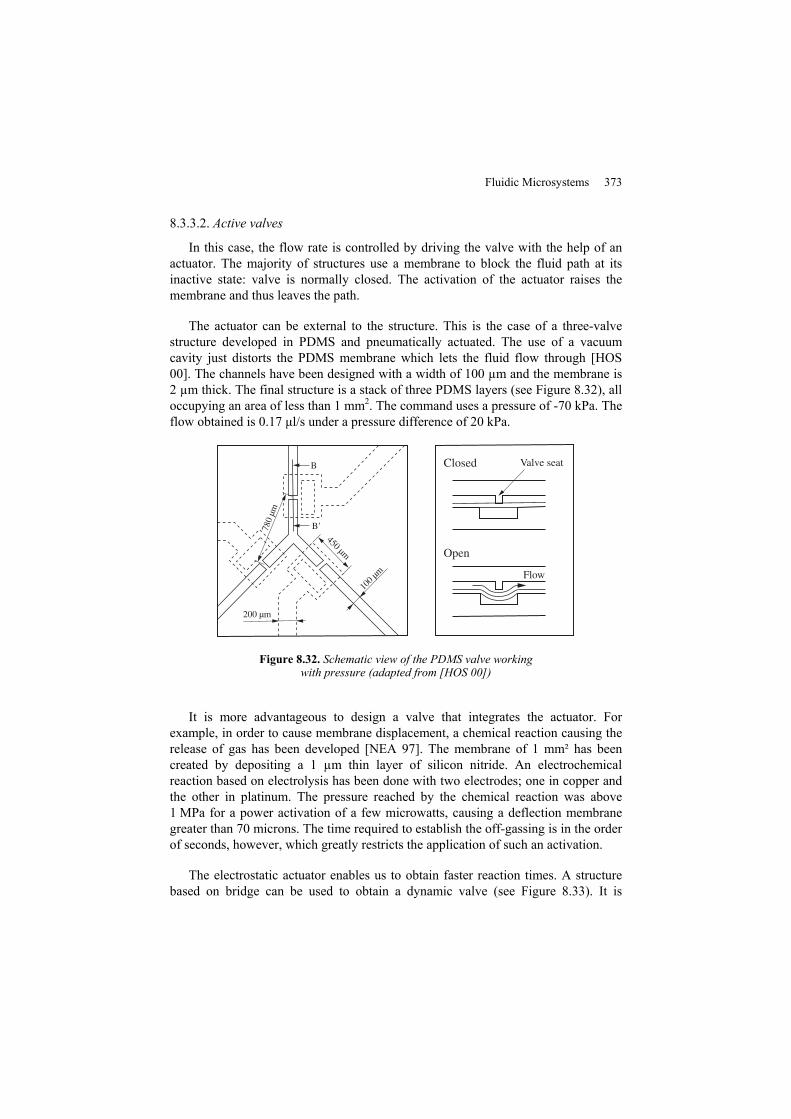
The actuator can be external to the structure. This is the case of a three-valve structure developed in PDMS and pneumatically actuated. The use of a vacuum cavity just distorts the PDMS membrane which lets the fluid flow through [HOS 00]. The channels have been designed with a width of 100 µm and the membrane is 2 µm thick. The final structure is a stack of three PDMS layers (see Figure 8.32), all occupying an area of less than 1 mm2. The command uses a pressure of -70 kPa. The flow obtained is 0.17 μl/s under a pressure difference of 20 kPa.
Figure 8.32. Schematic view of the PDMS valve working with pressure (adapted from [HOS 00])
It is more advantageous to design a valve that integrates the actuator. For example, in order to cause membrane displacement, a chemical reaction causing the release of gas has been developed [NEA 97]. The membrane of 1 mm² has been created by depositing a 1 µm thin layer of silicon nitride. An electrochemical reaction based on electrolysis has been done with two electrodes; one in copper and the other in platinum. The pressure reached by the chemical reaction was above 1 MPa for a power activation of a few microwatts, causing a deflection membrane greater than 70 microns. The time required to establish the off-gassing is in the order of seconds, however, which greatly restricts the application of such an activation.
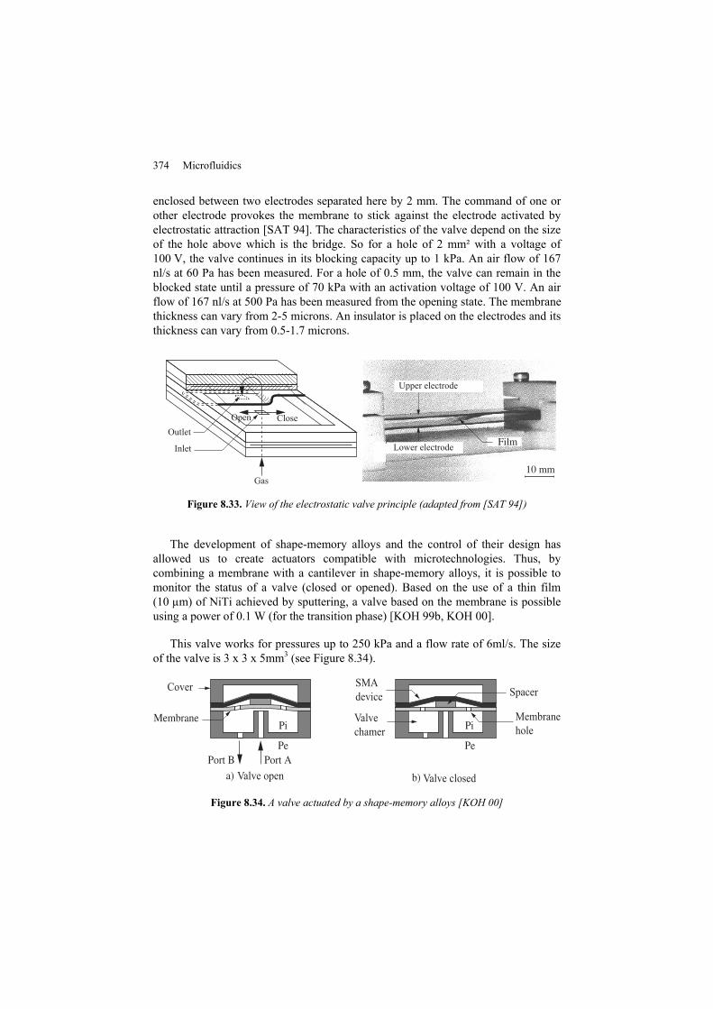
The electrostatic actuator enables us to obtain faster reaction times. A structure based on bridge can be used to obtain a dynamic valve (see Figure 8.33). It is
374 Microfluidics
enclosed between two electrodes separated here by 2 mm. The command of one or other electrode provokes the membrane to stick against the electrode activated by electrostatic attraction [SAT 94]. The characteristics of the valve depend on the size of the hole above which is the bridge. So for a hole of 2 mm² with a voltage of 100 V, the valve continues in its blocking capacity up to 1 kPa. An air flow of 167 nl/s at 60 Pa has been measured. For a hole of 0.5 mm, the valve can remain in the blocked state until a pressure of 70 kPa with an activation voltage of 100 V. An air flow of 167 nl/s at 500 Pa has been measured from the opening state. The membrane thickness can vary from 2-5 microns. An insulator is placed on the electrodes and its thickness can vary from 0.5-1.7 microns.
Figure 8.33. View of the electrostatic valve principle (adapted from [SAT 94])
The development of shape-memory alloys and the control of their design has allowed us to create actuators compatible with microtechnologies. Thus, by combining a membrane with a cantilever in shape-memory alloys, it is possible to monitor the status of a valve (closed or opened). Based on the use of a thin film (10 µm) of NiTi achieved by sputtering, a valve based on the membrane is possible using a power of 0.1 W (for the transition phase) [KOH 99b, KOH 00].
This valve works for pressures up to 250 kPa and a flow rate of 6ml/s. The size of the valve is 3 x 3 x 5mm3 (see Figure 8.34).
Figure 8.34. A valve actuated by a shape-memory alloys [KOH 00]
Fluidic Microsystems 375
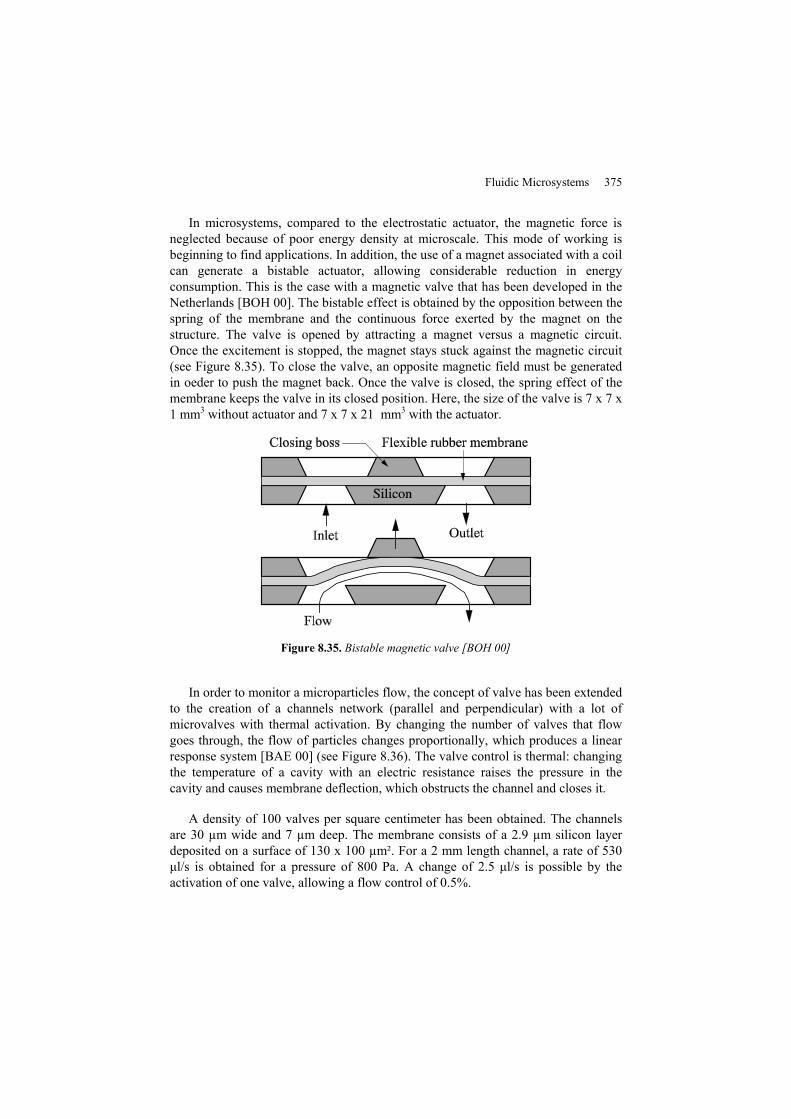
In microsystems, compared to the electrostatic actuator, the magnetic force is neglected because of poor energy density at microscale. This mode of working is beginning to find applications. In addition, the use of a magnet associated with a coil can generate a bistable actuator, allowing considerable reduction in energy consumption. This is the case with a magnetic valve that has been developed in the Netherlands [BOH 00]. The bistable effect is obtained by the opposition between the spring of the membrane and the continuous force exerted by the magnet on the structure. The valve is opened by attracting a magnet versus a magnetic circuit. Once the excitement is stopped, the magnet stays stuck against the magnetic circuit (see Figure 8.35). To close the valve, an opposite magnetic field must be generated in oeder to push the magnet back. Once the valve is closed, the spring effect of the membrane keeps the valve in its closed position. Here, the size of the valve is 7 x 7 x 1 mm3 without actuator and 7 x 7 x 21 mm3 with the actuator.
Figure 8.35. Bistable magnetic valve [BOH 00]
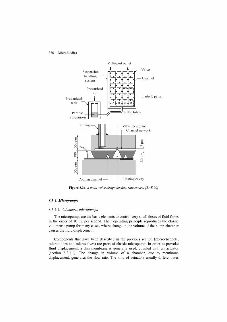
In order to monitor a microparticles flow, the concept of valve has been extended to the creation of a channels network (parallel and perpendicular) with a lot of microvalves with thermal activation. By changing the number of valves that flow goes through, the flow of particles changes proportionally, which produces a linear response system [BAE 00] (see Figure 8.36). The valve control is thermal: changing the temperature of a cavity with an electric resistance raises the pressure in the cavity and causes membrane deflection, which obstructs the channel and closes it.
A density of 100 valves per square centimeter has been obtained. The channels are 30 µm wide and 7 µm deep. The membrane consists of a 2.9 µm silicon layer deposited on a surface of 130 x 100 µm². For a 2 mm length channel, a rate of 530 μl/s is obtained for a pressure of 800 Pa. A change of 2.5 μl/s is possible by the activation of one valve, allowing a flow control of 0.5%.
376 Microfluidics
Figure 8.36. A multi-valve design for flow rate control [BAE 00]
8.3.4. Micropumps
8.3.4.1. Volumetric micropumps
The micropumps are the basic elements to control very small doses of fluid flows in the order of 10 nL per second. Their operating principle reproduces the classic volumetric pump for many cases, where change in the volume of the pump chamber causes the fluid displacement.
Components that have been described in the previous section (microchannels, microdiodes and microvalves) are parts of classic micropump. In order to provoke fluid displacement, a thin membrane is generally used, coupled with an actuator (section 8.2.1.1). The change in volume of a chamber, due to membrane displacement, generates the flow rate. The kind of actuators usually differentiates
Fluidic Microsystems 377
between the different micropumps. One of the major micropump applications is the print head inkjet. As an example, an electrostatically actuated inkjet printer has been developed by Seiko Epson (SEAJetTM: Static Electricity Actuated inkjet) [KAM 00]. This kind of actuator enables a print head with a low power consumption to be produced.
The inkjet is obtained from a deflection of a doped P+ silicon membrane (2.85 mm x 105 µm) of 2 µm thickness with a voltage of 26.5 V, with a gap between the membrane and electrode of 0.18 microns. Pressure generated by release of the membrane causes the expulsion of a droplet of ink in micrometer size (22.5 ng per droplet) which allows very high resolutions.
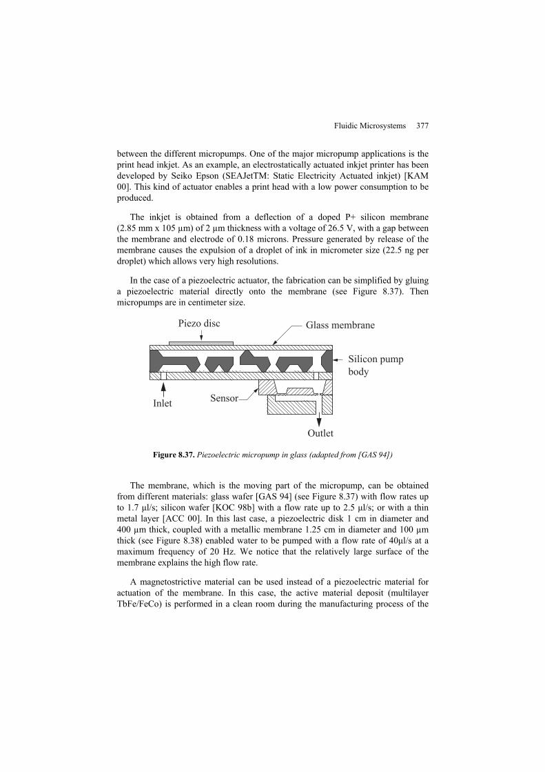
In the case of a piezoelectric actuator, the fabrication can be simplified by gluing a piezoelectric material directly onto the membrane (see Figure 8.37). Then micropumps are in centimeter size.
Piezo disc Glass membrane
Silicon pumpbody
Inlet Sensor
Outlet
Figure 8.37. Piezoelectric micropump in glass (adapted from [GAS 94])
The membrane, which is the moving part of the micropump, can be obtained from different materials: glass wafer [GAS 94] (see Figure 8.37) with flow rates up to 1.7 μl/s; silicon wafer [KOC 98b] with a flow rate up to 2.5 μl/s; or with a thin metal layer [ACC 00]. In this last case, a piezoelectric disk 1 cm in diameter and 400 µm thick, coupled with a metallic membrane 1.25 cm in diameter and 100 µm thick (see Figure 8.38) enabled water to be pumped with a flow rate of 40μl/s at a maximum frequency of 20 Hz. We notice that the relatively large surface of the membrane explains the high flow rate.
A magnetostrictive material can be used instead of a piezoelectric material for actuation of the membrane. In this case, the active material deposit (multilayer TbFe/FeCo) is performed in a clean room during the manufacturing process of the
378 Microfluidics
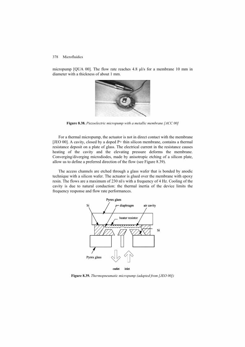
micropump [QUA 00]. The flow rate reaches 4.8 μl/s for a membrane 10 mm in diameter with a thickness of about 1 mm.
Figure 8.38. Piezoelectric micropump with a metallic membrane [ACC 00]
For a thermal micropump, the actuator is not in direct contact with the membrane [JEO 00]. A cavity, closed by a doped P+ thin silicon membrane, contains a thermal resistance deposit on a plate of glass. The electrical current in the resistance causes heating of the cavity and the elevating pressure deforms the membrane. Converging/diverging microdiodes, made by anisotropic etching of a silicon plate, allow us to define a preferred direction of the flow (see Figure 8.39).
The access channels are etched through a glass wafer that is bonded by anodic technique with a silicon wafer. The actuator is glued over the membrane with epoxy resin. The flows are a maximum of 230 nl/s with a frequency of 4 Hz. Cooling of the cavity is due to natural conduction: the thermal inertia of the device limits the frequency response and flow rate performances.
Figure 8.39. Thermopneumatic micropump (adapted from [JEO 00])
Fluidic Microsystems 379
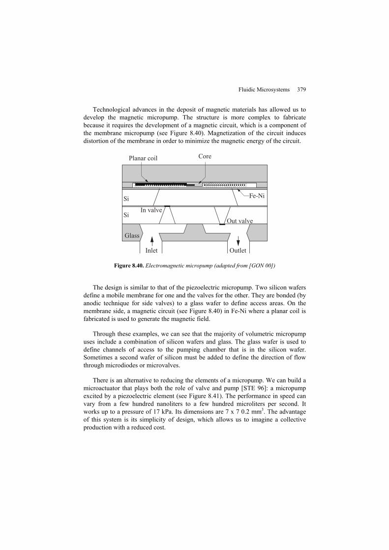
Technological advances in the deposit of magnetic materials has allowed us to develop the magnetic micropump. The structure is more complex to fabricate because it requires the development of a magnetic circuit, which is a component of the membrane micropump (see Figure 8.40). Magnetization of the circuit induces distortion of the membrane in order to minimize the magnetic energy of the circuit.
Planar coil Core
In valveOut valve
Glass
Inlet Outlet
Figure 8.40. Electromagnetic micropump (adapted from [GON 00])
The design is similar to that of the piezoelectric micropump. Two silicon wafers define a mobile membrane for one and the valves for the other. They are bonded (by anodic technique for side valves) to a glass wafer to define access areas. On the membrane side, a magnetic circuit (see Figure 8.40) in Fe-Ni where a planar coil is fabricated is used to generate the magnetic field.
Through these examples, we can see that the majority of volumetric micropump uses include a combination of silicon wafers and glass. The glass wafer is used to define channels of access to the pumping chamber that is in the silicon wafer. Sometimes a second wafer of silicon must be added to define the direction of flow through microdiodes or microvalves.
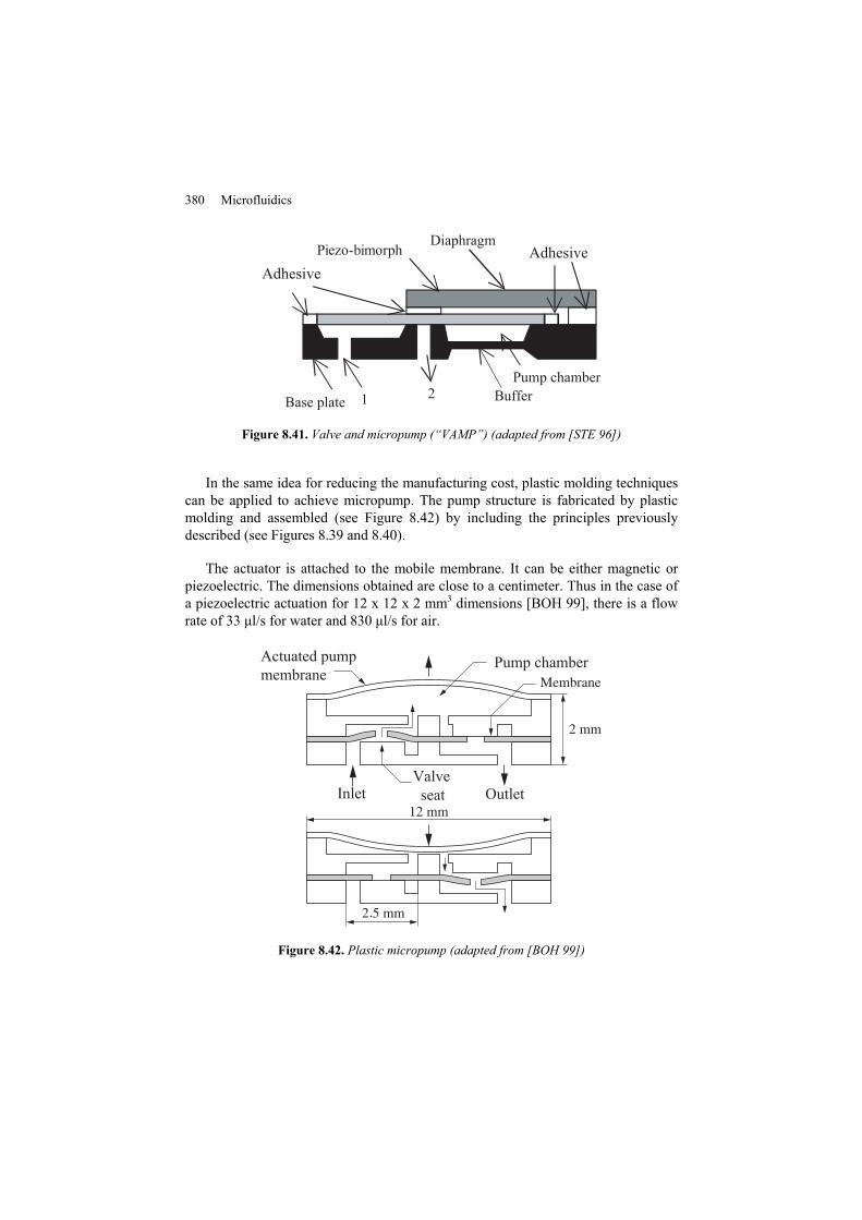
There is an alternative to reducing the elements of a micropump. We can build a microactuator that plays both the role of valve and pump [STE 96]: a micropump excited by a piezoelectric element (see Figure 8.41). The performance in speed can vary from a few hundred nanoliters to a few hundred microliters per second. It works up to a pressure of 17 kPa. Its dimensions are 7 x 7 0.2 mm3. The advantage of this system is its simplicity of design, which allows us to imagine a collective production with a reduced cost.
380 Microfluidics
Figure 8.41. Valve and micropump (“VAMP”) (adapted from [STE 96])
In the same idea for reducing the manufacturing cost, plastic molding techniques can be applied to achieve micropump. The pump structure is fabricated by plastic molding and assembled (see Figure 8.42) by including the principles previously described (see Figures 8.39 and 8.40).
The actuator is attached to the mobile membrane. It can be either magnetic or piezoelectric. The dimensions obtained are close to a centimeter. Thus in the case of a piezoelectric actuation for 12 x 12 x 2 mm3 dimensions [BOH 99], there is a flow rate of 33 μl/s for water and 830 μl/s for air.
.
Actuated pumpmembrane
Pump chamber
InletValve seat Outlet
Figure 8.42. Plastic micropump (adapted from [BOH 99])

Fluidic Microsystems 381
8.3.4.2. Electrohydrodynamic and magnetohydrodynamic micropump
For this kind of micropump, there is no mobile part. The generation of an electric or magnetic field creates the liquid movement. Liquids need to interact with the field applied to them.
Magnetohydrodynamic micropumps are reduced to a channel etched on a silicon wafer with two electrodes on its walls that can generate a current in the liquid (see Figure 8.43). The application of a magnetic field, perpendicular to this current, allows the fluid to move via Lorentz forces. The magnetic field can be generated by permanent magnets [JAN 00] that interact with the current. Application of a direct current can cause the creation of bubbles by electrolytic reaction. To avoid this reaction, we can apply an alternative field, synchronous to the excitation current [LEM 00]. Although the average current applied is zero, the Lorentz force resulting from the product between current and the field is a non-zero average value.
The channel is closed by two glass wafers bonded by an anodic technique. One glass wafer is etched so as to allow access to electrical connections and also the flow direction (see Figure 8.43). Flow rates of up to 330 nL/s were achieved with this structure, where the channel is 380 µm deep and 800 µm wide [LEM 00]. Instead of using a magnetic field, it is also possible to move liquid with an electric field. This is the effect used for electrohydrodynamic pumps. In this case, a network of electrodes is deposited on a wafer glass at the bottom of the channel. The electric field created between the electrodes acts on the charges injected into the fluid by emitting electrodes. The displacement of these charges causes the fluid to move [AHN 98].
Figure 8.43. Alternate current magnetohydrodynamic micropump (adapted from [LEM 00])
382 Microfluidics
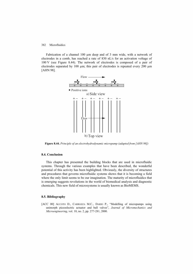
Fabrication of a channel 100 µm deep and of 3 mm wide, with a network of electrodes in a comb, has reached a rate of 830 nL/s for an activation voltage of 100 V (see Figure 8.44). The network of electrodes is composed of a pair of electrodes separated by 100 µm; this pair of electrodes is repeated every 200 µm [AHN 98].
Figure 8.44. Principle of an electrohydrodynamic micropump (adapted from [AHN 98])
8.4. Conclusion
This chapter has presented the building blocks that are used in microfluidic systems. Through the various examples that have been described, the wonderful potential of this activity has been highlighted. Obviously, the diversity of structures and procedures that governs microfluidic systems shows that it is becoming a field where the only limit seems to be our imagination. The maturity of microfluidics that is emerging suggests revolutions in the world of biomedical analysis and diagnostic chemicals. This new field of microsystems is usually known as BioMEMS.
8.5. Bibliography
[ACC 00] ACCOTO D., CARROZZA M.C., DARIO P., “Modelling of micropumps using unimorph piezoelectric actuator and ball valves”, Journal of Micromechanics and Microengineering, vol. 10, no. 2, pp. 277-281, 2000.
Fluidic Microsystems 383
[ACE 97] ACERO M.C., PLAZA J.A., ESTEVE J., CARMONA M., MARCO S., SAMITIER J., “Design of a modular micropump based on anodic bonding”, Journal of Micromechanics and Microengineering, vol. 7, pp. 179-182, 1997.
[AHN 98] AHN S.-H., KIM Y.-K., “Fabrication and experiment of a planar micro ion drag pump”, Sensors and Actuators A, vol. 70, no. 1-2, pp. 1-5, 1998.
[AND 01] ANDUZE M., COLIN S., CAEN R., CAMON H., CONEDERA V., DO CONTO T., “Analysis and testing of a fluidic vortex microdiode”, Journal of Micromechanics and Microengineering, vol. 11, no. 2, pp. 108-112, 2001.
[AUB 98] AUBERT C., COLIN S., CAEN R., “Unsteady gaseous flows in tapered microchannels”, First International Conference on Modeling and Simulation of Microsystems, Semiconductors, Sensors and Actuators (MSM'98), vol. 1, pp. 486-491, 1998.
[BAE 00] BAECHI D., BUSER R., “Suspension handling system”, Sensors and Actuators A, vol. 63, pp. 195-200, 2000.
[BAK 67] BAKER P., “A comparison of fluid diodes”, Second Crandfield Fluidics Conference. Cambridge, pp. d6/88-d6/116, 1967.
[BAL 01] BÁLINT G., Étude et modélisation numérique du fonctionnement de microvalves, PhD thesis, Toulouse, National Institute of Applied Sciences at Toulouse and the Technical University of Budapest, 2001.
[BEC 98] BECKER H., LOWACK K., MANZ A., “Planar quartz chips with submicron channels for two-dimensional capillary electrophoresis applications”, Journal of Micromechanics and Microengineering, vol. 8, pp. 24-28, 1998.
[BOH 00] BÖHM S., BURGER G.J., KORTHORST M.T., ROSEBOOM F., “A micromachined silicon valve driven by a miniature bi-stable electro-magnetic actuator”, Sensors and Actuators A, vol. 80, no. 1, pp. 77-83, 2000.
[BOH 99] BÖHM S., OLTHUIS W., BERGVELD P., “A plastic micropump constructed with conventional techniques and materials”, Sensors and Actuators A, vol. 77, no. 3, pp. 223-228, 1999.
[BOS 93] BOSCH D., HEIMHOFER B., MÜCK G., SEIDEL H., THUMSER U., WELSER W., “A silicon microvalve with combined electromagnetic/electrostatic actuation”, Sensors and Actuators A, vol. 37-38, pp. 684-692, 1993.
[BOU 96] BOUROUINA T., GRANDCHAMP J.-P., “Modeling micropumps with electrical equivalent networks”, Journal of Micromechanics and Microengineering, vol. 6, pp. 398-404, 1996.
[BOU 97] BOUROUINA T., BOSSEBOEUF A., GRANDCHAMP J.-P., “Design and simulation of an electrostatic micropump for drug-delivery applications”, Journal of Micromechanics and Microengineering, vol. 7, pp. 186-188, 1997.
[CAR 99] CARMONA M., MARCO S., SIEIRO J., RUIZ O., GOMEZ-CAMA J.M., SAMITIER J., “Modelling of microsystems with analog hardware description languages”, Sensors and Actuators A, vol. 76, pp. 32-42, 1999.

384 Microfluidics
[CNR 99] CNRS, Micromed II: Rapport Final, CNRS 1999.
[CRO 80] CROWLEY J.M., “The efficiency of electrohydrodynamic pumps in the attraction mode”, Journal of Electrostatics, vol. 8, pp. 171-181, 1980.
[DUF 99] DUFFY D.C., SCHUELLER O.J.A., BRITTAIN S.T., WHITESIDES G.M., “Rapid prototyping of microfluidic switches in poly(dimethyl siloxane) and their actuation by electro-osmotic flow”, Journal of Micromechanics and Microengineering, vol. 9, pp. 211-217, 1999.
[FOR 95] FORSTER F.K., BARDELL R.L., AFROMOWITZ M.A., SHARMA N.R., BLANCHARD A., “Design, fabrication and testing of fixed-valve micro-pumps”, Proceedings of the Fluids Engineering Division of the ASME - FED, vol. 234, pp. 39-44, 1995.
[FUH 94] FUHR G., SCHNELLE T., WAGNER B., “Travelling wave-driven microfabricated electrohydrodynamic pumps for liquids”, Journal of Micromechanics and Microengineering, vol. 4, pp. 217-226, 1994.
[GAS 94] GASS V., VAN DER SCHOOT B.H., JEANNERET S., DE ROOIJ N.F., “Integrated flow-regulated silicon micropump”, Sensors and Actuators A, vol. 43, pp. 335-338, 1994.
[GER 95] GERLACH T., SCHUENEMANN M., WURMUS H., “A new micropump principle of the reciprocating type using pyramidic micro flowchannels as passive valves”, Journal of Micromechanics and Microengineering, vol. 5, no. 2, pp. 199-201, 1995.
[GER 98] GERLACH T., “Microdiffusers as dynamic passive valves for micropump applications”, Sensors and Actuators A, vol. 69, no. 2, pp. 181-191, 1998.
[GOL 97] GOLL C., BACHER W., BÜSTGENS B., MAAS D., RUPRECHT R., SCHOMBURG W.K., “An electrostatically actuated polymer microvalve equipped with a movable membrane electrode”, Journal of Micromechanics and Microengineering, vol. 7, pp. 224-226, 1997.
[GON 00] GONG Q., ZHOU Z., YANG Y., WANG X., “Design, optimization and simulation on microelectromagnetic pump”, Sensors and Actuators A, vol. 83, no. 1-2, pp. 200-207, 2000.
[GUI 61] GUILLON M., Etude et Détermination des Systèmes Hydrauliques. Paris, Dunod, 1961.
[HAR 99] HARTEMANN P., “Effets et matériaux magnétostrictifs”, Techniques de l'Ingénieur, vol. E1, p. E1880, 1999.
[HES 97] HESCHEL M., MÜLLENBORN M., BOUWSTRA S., “Fabrication and characterization of truly 3-D diffuser-nozzle microstructures in silicon”, Journal of Micromechanics and Microengineering, vol. 6, pp. 41-47, 1997.
[HOB 70] HOBSON J.P., “Accommodation pumping - A new principle for low pressure”, Journal of Vacuum Science and Technology, vol. 7, no. 2, pp. 301-357, 1970.
[HOB 00] HOBSON J.P., SALZMAN D.B., “Review of pumping by thermal molecular pressure”, Journal of Vacuum Science and Technology A, vol. 18, no. 4, pp. 1758-1765, 2000.
Fluidic Microsystems 385
[HOS 00] HOSOKAWA K., MAEDA R., “A pneumatically-actuated three-way microvalve fabricated with polydimethylsiloxane using the membrane transfer technique”, Journal of Micromechanics and Microengineering, vol. 10, no. 3, pp. 415-420, 2000.
[IKE 90] IKEDA T., Fundamentals of Piezoelectricity. Oxford, Oxford University Press, 1990.
[JAN 00] JANG J., LEE S.S., “Theoretical and experimental study of MHD (magnetohydrodynamic) micropump”, Sensors and Actuators A, vol. 80, no. 1, pp. 84-89, 2000.
[JEO 00] JEONG O.C., YANG S.S., “Fabrication and test of a thermopneumatic micropump with a corrugated p+ diaphragm”, Sensors and Actuators A, vol. 83, no. 1-2, pp. 249-255, 2000.
[JER 94] JERMAN J.H., “Electrically-activated, normally-closed diaphragm valves”, Journal of Micromechanics and Microengineering, vol. 4, pp. 210-216, 1994.
[KAM 00] KAMISUKI S., FUJII M., TAKEKOSHI T., TEZUKA C., ATOBE M., “A high resolution electrostatically driven commercial inkjet head”, 13th Annual International Conference on Micro Electro Mechanical Systems, p. 793-798, 2000.
[KOC 96] KOCH M., EVANS A.G.R., BRUNNSCHWEILER A., “Coupled FEM simulation for the characterization of the fluid flow within a micromachined cantilever valve”, Journal of Micromechanics and Microengineering, vol. 6, pp. 112-114, 1996.
[KOC 97] KOCH M., EVANS A.G.R., BRUNNSCHWEILER A., “Simulation and fabrication of micromachined cantilever valves”, Sensors and Actuators A, vol. 62, pp. 756-759, 1997.
[KOC 98a] KOCH M., HARRIS N., EVANS A.G.R., WHITE N.M., BRUNNSCHWEILER A., “A novel micromachined pump based on thick-film piezoelectric actuation”, Sensors and Actuators A, vol. 70, no. 1-2, pp. 98-103, 1998.
[KOC 98b] KOCH M., EVANS A.G.R., BRUNNSCHWEILER A., “The dynamic micropump driven with a screen printed PZT actuator”, Journal of Micromechanics and Microengineering, vol. 8, pp. 119-122, 1998.
[KOH 99a] KOHL M., SKROBANEK K.D., MIYAZAKI S., “Development of stress-optimised shape memory microvalves”, Sensors and Actuators A, vol. 72, no. 3, pp. 243-250, 1999.
[KOH 99b] KOHL M., DITTMANN D., QUANDT E., WINZEK B., MIYAZAKI S., ALLEN D.M., “Shape memory microvalves based on thin films or rolled sheets”, Materials Science and Engineering, vol. A273-275, pp. 784-788, 1999.
[KOH 00] KOHL M., DITTMANN D., QUANDT E., WINZEK B., “Thin film shape memory microvalves with adjustable operation temperature”, Sensors and Actuators A, vol. 83, no. 1-2, pp. 214-219, 2000.
[LEM 00] LEMOFF A.V., LEE A.P., “An AC magnetohydrodynamic micropump”, Sensors and Actuators B, vol. 63, pp. 178-185, 2000.
[LIN 98] LINNEMANN R., WOIAS P., SENFFT C.D., DITTERICH J.A., “A self priming and bubble-tolerant piezoelectric silicon micropump for liquids and gases”, IEEE Micro Electro Mechanical Systems Workshop, Heidelberg, Germany, p. 532-537, 1998.
386 Microfluidics
[MAK 00] MAKINO E., MITSUYA T., SHIBATA T., “Micromachining of TiNi shape memory thin film for fabrication of micropump”, Sensors and Actuators A, vol. 79, pp. 251-259, 2000.
[MEL 81] MELCHER J.R., Continuum Electromechanics, Cambridge, MIT Press, 1981.
[MOR 92] MOREAU R., “Écoulement d'un métal liquide en présence d'un champ magnétique”, Techniques de l’Ingénieur, vol. D31, pp. D2950, 1992.
[NEA 97] NEAGU C.R., GARDENIERS J.G.E., ELWENSPOEK M.C., KELLY J.J., “An electrochemical active valve”, Electrochimica Acta, vol. 42, no. 20-22, pp. 3367-3373, 1997.
[NGU 99] NGUYEN N.T., WHITE R.M., “Design and optimization of an ultrasonic flexural plate wave micropump using numerical simulation”, Sensors and Actuators A, vol. 77, no. 3, pp. 229-236, 1999.
[OLS 98] OLSSON A., Valve-less diffuser micropumps, PhD Thesis, Stockholm, Royal Institute of Technology, 1998.
[OLS 99] OLSSON A., STEMME G., STEMME E., “A numerical design study of the valveless diffuser pump using a lumped-mass model”, Journal of Micromechanics and Microengineering, vol. 9, pp. 34-44, 1999.
[OLS 00] OLSSON A., STEMME G., STEMME E., “Numerical and experimental studies of flat-walled diffuser elements for valve-less micropumps”, Sensors and Actuators A, vol. 84, no. 1-2, pp. 165-175, 2000.
[OOS 99] OOSTERBROEK R.E., BERENSCHOT J.W., SCHLAUTMANN S., KRIJNEN G.J.M., LAMMERINK T.S.J., ELWENSPOEK M.C., VAN DEN BERG A., “Designing, simulation and realization of in-plane operating micro valves, using new etching techniques”, Journal of Micromechanics and Microengineering, vol. 9, pp. 194-198, 1999.
[PAR 99] PARK J.H., YOSHIDA K., YOKOTA S., “Resonantly driven piezoelectric micropump. Fabrication of a micropump having high power density”, Mechatronics, vol. 9, no. 7, pp. 687-702, 1999.
[PAT 90] PATOOR E., BERVEILLER M., Les alliages à mémoire de forme, Paris, Hermes, 1990.
[PAU 00] PAUL B.K., TERHAAR T., “Comparison of two passive microvalve designs for microlamination architectures”, Journal of Micromechanics and Microengineering, vol. 10, no. 1, pp. 15-20, 2000.
[QUA 00] QUANDT E., LUDWIG A., “Magnetostrictive actuation in microsystems”, Sensors and Actuators A, vol. 81, no. 1-3, pp. 275-180, 2000.
[RIC 91] RICHTER A., PLETTNER A., HOFMANN K.A., SANDMAIER H., “A micromachined electrohydrodynamic (EHD) pump”, Sensors and Actuators A, vol. 29, pp. 159-168, 1991.
[ROY 96] ROYER D., DIEULESAINT E., Ondes Élastiques dans les Solides, Paris, Masson, 1996.
Fluidic Microsystems 387
[SAT 94] SATO K., SHIKIDA M., “An electrostatically actuated gas valve with an S-shaped film element”, Journal of Micromechanics and Microengineering, vol. 4, pp. 206-209, 1994.
[SCH 94] SCHOMBURG W.K., VOLLMER J., BÜSTGENS B., FAHRENBERG J., HEIN H., MENZ W., “Microfluidic components in LIGA technique” Journal of Micromechanics and Microengineering, vol. 4, pp. 186-191, 1994.
[SCH 98] SCHUELLER O.J.A., DUFFY D.C., ROGERS J.A., BRITTAIN S.T., WHITESIDES G.M., “Reconfigurable diffraction gratings based on elastomeric microfluidic devices”, Sensors and Actuators A, vol. 78, pp. 149-159, 1998.
[SHI 94] SHIKIDA M., SATO K., TANAKA S., KAWAMURA Y., FUJISAKI Y., “Electrostatically driven gas valve with high conductance”, Journal of Microelectromechanical Systems, vol. 3, no. 2, pp. 76-80, 1994.
[SMI 90] SMITS J.G., “Piezoelectric micropump with three valves working peristaltically”, Sensors and Actuators, vol. A21-A23, pp. 203-206, 1990.
[STE 96] STEHR M., MESSNER S., SANDMAIER H., ZENGERLE R., “The VAMP - A new device for handling liquids or gases”, Sensors and Actuators A, vol. 57, no. 2, pp. 153-157, 1996.
[TES 20] TESLA N., Valvular Conduit. US Patent 1 329 559, 1920.
[TIR 89] TIRÉN J., TENERZ L., HÖK B., “A batch-fabricated non-reverse valve with cantilever beam manufactured by micromachining of silicon”, Sensors and Actuators, vol. 18, pp. 389-396, 1989.
[ULL 98] ULLMANN A., “The piezoelectric valve-less pump – Performance enhancement analysis”, Sensors and Actuators A, vol. 69, no. 1, pp. 97-105, 1998.
[VAN 90] VAN DE POL F.C.M., VAN LINTEL H.T.G., ELWENSPOEK M., FLUITMAN J.H.J., “A thermopneumatic micropump based on micro-engineering techniques”, Sensors and Actuators, vol. A21-A23, pp. 198-202, 1990.
[VEE 99] VEENSTRA T.T., LAMMERINK T.S.J., ELWENSPOEK M.C., VAN DEN BERG A., “Characterization method for a new diffusion mixer applicable in micro flow injection analysis systems”, Journal of Micromechanics and Microengineering, vol. 9, pp. 199-202, 1999.
[VOI 98] VOIGT P., SCHRAG G., WACHUTKA G., “Microfluidic system modeling using VHDL-AMS and circuit simulation”, Microelectronics Journal, vol. 29, pp. 791-797, 1998.
[YAN 96] YANG E.H., HAN S.W., YANG S.S., “Fabrication and testing of a pair of passive bivalvular microvalves composed of p+ silicon diaphragms”, Sensors and Actuators A, vol. 57, pp. 75-78, 1996.
[YOU 99] YOUNG R.M., “Analysis of a micromachine based vacuum pump on a chip actuated by the thermal transpiration effect”, Journal of Vacuum Science Technology B, vol. 17, no. 2, pp. 280-287, 1999.
388 Microfluidics
[ZEN 94] ZENGERLE R., RICHTER M., “Simulation of microfluid systems”, Journal of Micromechanics and Microengineering, vol. 4, no. 4, pp. 192-204, 1994.
[ZEN 95] ZENGERLE R., ULRICH J., KLUGE S., RICHTER M., RICHTER A., “A bidirectional silicon micropump”, Sensors and Actuators A, vol. 50, pp. 81-86, 1995.