microcontroller-based mobile robot positioning and obstacle avoidance
TRANSCRIPT
Available online at www.sciencedirect.com
ScienceDirect
Journal of Electrical Systems and Information Technology 1 (2014) 58–71
Microcontroller-based mobile robot positioning and obstacleavoidance
Aziza M. Zaki ∗, Osama Arafa, Sanaa I. AmerPower Electronics and Energy Conversion Department, Electronics Research Institute, El-Tahrir Street, Dokki, Cairo, Egypt
Available online 4 April 2014
Abstract
The use of mobile robots is growing in manufacturing facilities, hazardous materials handling, etc. Usually, several sensor systemsare used in combination. The task of combining the information into a usable form, suitable for making navigation decisions, isknown as sensor fusion. In this paper, the navigation system built on a mobile robot operating in a warehouse is presented focusing onthe sensory system used. Hybrid navigation system that combines the perception and dead reckoning is used and gives satisfactoryoperation. A microcontroller system is designed to control the navigation of a mobile robot while avoiding obstacles. A system of24 ultrasonic sensors was designed and the operation algorithms were described. The encoder and the ultrasonic sensors used arepresented in detail together with the navigation system designed based on their operation.© 2014 Production and hosting by Elsevier B.V. on behalf of Electronics Research Institute (ERI).
Keywords: Mobile robot; Navigation control; Odometry; Ultrasonic sensors; Microcontroller
1. Introduction
Robot navigation means the ability to wonder in the environment without colliding with obstacles, the ability todetermine one’s own position, and the ability to reach certain goal locations. So, navigation system may imply thefollowing components: robot positioning system, path planning and map building. These are four popular positioningsystems:
1. Odometry (dead reckoning)-based navigation.2. Active beacons-based navigation system.
3. Landmark-based navigation system.4. Map-based navigation system.∗ Corresponding author.E-mail address: [email protected] (A.M. Zaki).Peer review under the responsibility of Electronics Research Institute (ERI).
http://dx.doi.org/10.1016/j.jesit.2014.03.0092314-7172/© 2014 Production and hosting by Elsevier B.V. on behalf of Electronics Research Institute (ERI).
srafSt
ai
ti
solteiRcd
sSdh7a
2
poop1
itpwTm
a(1
A.M. Zaki et al. / Journal of Electrical Systems and Information Technology 1 (2014) 58–71 59
Most autonomous robotic systems will have multiple sensors (Brooks, 1986; Mogensen, 2006). Usually severalensor systems are used in combination. These are sometimes complementary, sometimes redundant. In almost allobot systems, multiple sensors from the same type or different types are used to give complete coverage, for example
ring of 24 ultrasonic sensors in 15◦ increments around a vehicle, mobile robot CARMEL (Computer-Aided Robotor Maintenance, Emergency and Life support) (Borenstein and Koren, 1991). Another example is the Nomad Suppercout II which carries 16 ultrasonic sensors separated by 22.5◦ around the vehicle (Yi, 2001). The task of combining
he information into a usable form, suitable for making navigation decisions, is known as sensor fusion.Mobile robots generally carry dead reckoning sensors such as wheel encoders and inertial sensors and also landmark
nd obstacle detecting and map making sensors such as time of flight (TOF) ultrasonic sensors. Sensors measurementsn this case are to be fused to estimate the robot’s position.
Vision sensors are used in many applications to build an image of the space confronting the mobile robot in ordero detect any obstacle and avoid collisions. Vision systems are usually computationally expensive as image formations too complicated for many applications.
In this paper, the navigation system built on a mobile robot operating in a warehouse is presented. Hybrid navigationystem that combines the perception and dead reckoning was found to be complementary and gives a satisfactoryperation of the mobile robot. If environment contains confusing information or few perceptually distinguishableandmarks, the performance of these systems decline. The perceptual aliasing problem can be solved by includinghe odometry data to discriminate between the similar places. The use of ultrasonic sensors in most applications isasier, cheaper and computationally simpler. Ultrasonic transducers are preferably used to obtain three-dimensionalnformation of the environment (Bak, 2002; Everett, 1995; Borenstein and Koren, 1988; Benitz-Read and Rojas-amirez, 2010). They measure and detect distances to moving objects, are impervious to target materials, surface andolor, solid-state units have virtually unlimited maintenance-free lifespan. Ultrasonic sensors are not affected by dust,irt or high-moisture environment.
In Section 2 of this work, the odometry and the odometry errors were presented. Section 3 presents ultrasonicystems, the source of errors that could be encountered and the sensors type specially the sensor used in this work.ection 4 presents the robot description and the sensors, decoders and encoders built on the robot while Section 5escribes the robot controller designed for robot operation with the ultrasonic sensors used clustering and the controllerardware and software. Section 6 details the proposed robot navigation inside and outside the warehouse while Section
presents the experimental testing together with the interface board used. Sections 8 and 9 give the results discussionnd conclusions.
. Odometry and odometry errors
Odometry is the most widely used navigation method for mobile robot positioning. It is well known that odometryrovides good short term accuracy, is inexpensive and allows very high sampling rates. However, the fundamental ideaf odometry is the integration of incremental motion information over time, which leads inevitably to the accumulationf errors. Odometry is used in almost all mobile robots for various reasons: Odometry data can be fused with absoluteosition measurements to provide better and more reliable position estimation (Chenavier and Crowley, in press; Evans,994). Odometry can be used in between absolute position updates with landmarks.
Odometry is based on simple equations that are easily implemented and that utilize data from inexpensivencremental wheel encoders. However, odometry is also based on the assumption that wheel revolutions can beranslated into linear displacement relative to the floor. This assumption is of limited validity. One extreme exam-le is wheel slippage: – if one wheel was to slip on, say an oil spill, then the associated encoder would registerheel revolutions even though these revolutions would not correspond to a linear displacement of the wheel.here are also, several other subtle reasons for inaccuracies in the translation of wheel encoder readings into linearotion.
To correct the errors in positioning resulting from the odometry system and for safe navigation and obstaclevoidance, ultrasonic sensors are frequently used as they can provide good range information based on the time of flightTOF) principle. They have been widely used in mobile robot applications (Elfes, 1987; Leonard and Durrant-Whyte,992; Borthwick and Durrant-Whyte, 1994).
60 A.M. Zaki et al. / Journal of Electrical Systems and Information Technology 1 (2014) 58–71
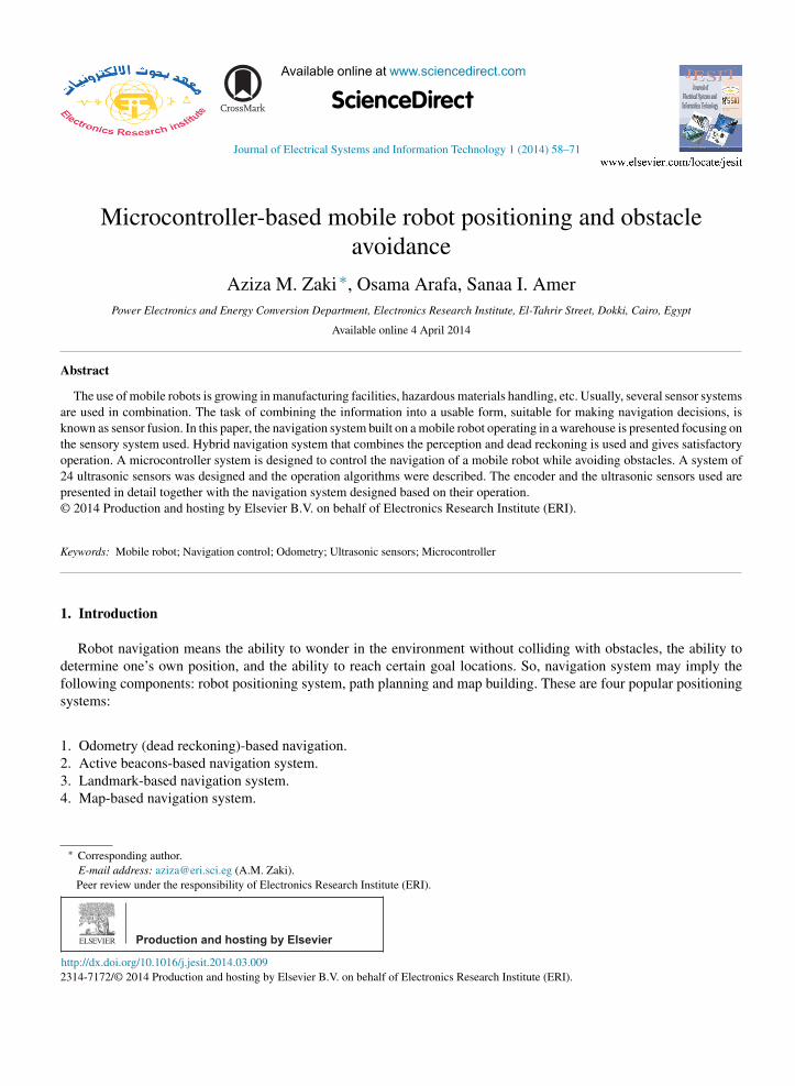
Fig. 1. Angular error of an ultrasonic sensor α is the half opening angle of sonar cone, R is a sonar response.
3. Ultrasonic systems
Ultrasonic TOF ranging is today the most common technique employed on indoor mobile robotic systems, primarilydue to the ready availability of low-cost systems and their ease of interface.
3.1. Ultrasonic sensors
Ultrasonic transducers are preferably used to obtain three-dimensional information of the environment. But someproblems appear in sonar response. Ultrasonic sensors suffer from unreliable sonar responses from the environment.For sonar-based mobile robot in confined space, special attention should be paid to these problems. The space isnormally a closed environment.
Two major problems are discussed in the following (Kumari, 2012).
3.1.1. Angular uncertaintyWhen an ultrasonic sensor gets a range response of R meters, the response simply represents a cone within which
the object may be present. There is no way to pin-point exactly where the position of the object is. Fig. 1 conveys theidea. The opening angle of the ultrasonic sensor is 2α and the object can be anywhere in the shaded region for theresponse R.
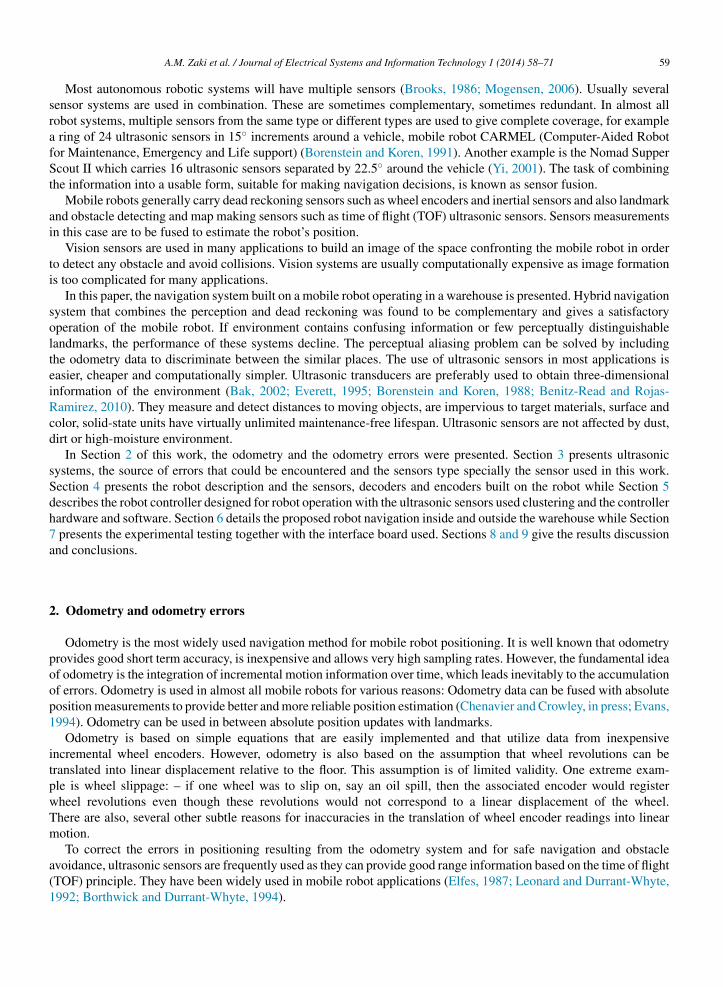
3.1.2. Specular reflectionSpecular reflection refers to the sonar response that is not reflected back directly from the target object. In specular
reflection, the ultrasound is reflected away from the reflecting surface, which results in longer range reporting or missingthe detection of object all together, Fig. 2 (Drumheller, 1987; Lim and Cho, 1994).
3.2. Types of ultrasonic sensor
Before we select or install an ultrasonic sensor, we should be familiar with these terms:
1. Dead zone.2. Beam angle.3. Beam cone diameter.4. Maximum sensing range.5. Background suppression.6. Switching frequency.7. Inclination of target.8. Environmental considerations.
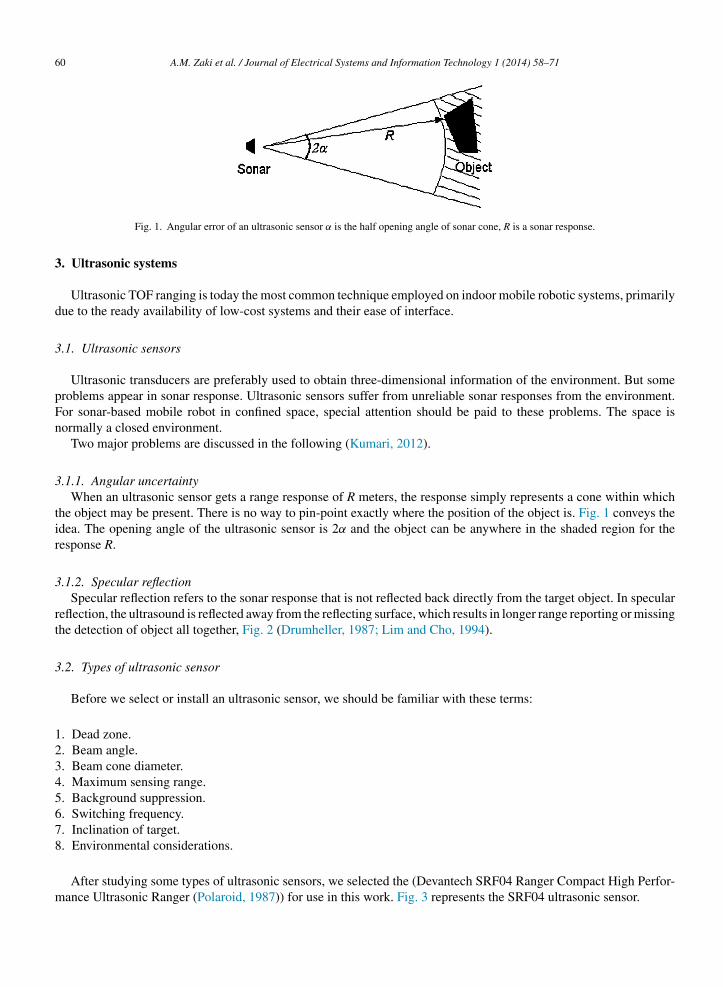
After studying some types of ultrasonic sensors, we selected the (Devantech SRF04 Ranger Compact High Perfor-mance Ultrasonic Ranger (Polaroid, 1987)) for use in this work. Fig. 3 represents the SRF04 ultrasonic sensor.
A.M. Zaki et al. / Journal of Electrical Systems and Information Technology 1 (2014) 58–71 61
Fig. 2. Specular reflections.
3
co
sa
4
s
12345
Fig. 3. Devantech SRF04 range.
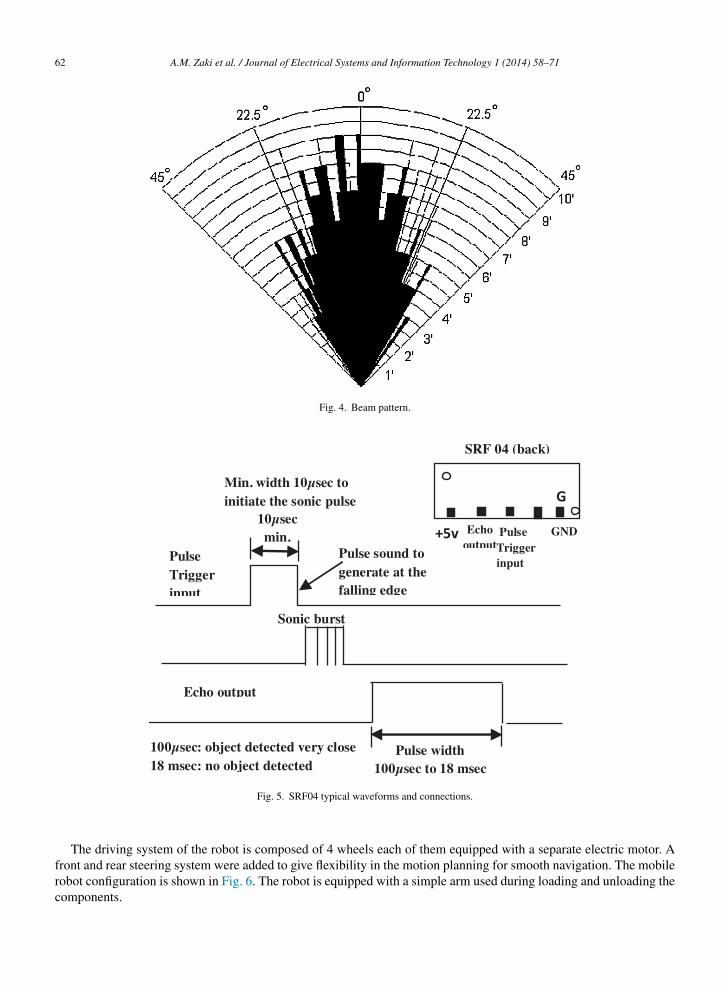
.2.1. SpecificationsThe specifications of SRF04 Ultrasonic Ranger are shown in the Appendix. The beam pattern of the SRF04 is
onical with the width of the beam being a function of the surface area of the transducers and is fixed. The beam patternf the transducers used on the SRF04, taken from the manufacturer’s data sheet, is shown in Fig. 4.
The ranger works by transmitting a pulse of sound outside the range of human hearing. This pulse travels at thepeed of sound (roughly 0.9 ft/m s) away from the ranger in a cone shape and the sound reflects back to the ranger fromny object in the path of this sonic wave, Fig. 5.
. Robot description
The mechanical design for the robot plays a critical role in the success of the robot facility. The followingpecifications should be met:
. Moving forward and backward without rotation.
. Moving aside (right and left) without rotation.
. Have the facility to rotate in a complete circle.
. The robot will use a battery assembly with total volt 48 V.
. The control unit and battery charger should be on the robot itself.
62 A.M. Zaki et al. / Journal of Electrical Systems and Information Technology 1 (2014) 58–71
Fig. 4. Beam pattern.
100µse c: object detected very close18 msec: no object detecte d
Pulse sound togenerate at thefalling ed ge
10µsecmin.
Puls eTrigg erinput
Min. width 10µsec toinitiate the sonic pu lse
Sonic burst
SRF 04 (ba ck)
Echooutpu t
PulseTri ggerinput
G
+5v GND
Echo outpu t
Pulse widt h100µsec to 18 msec
Fig. 5. SRF04 typical waveforms and connections.
The driving system of the robot is composed of 4 wheels each of them equipped with a separate electric motor. Afront and rear steering system were added to give flexibility in the motion planning for smooth navigation. The mobilerobot configuration is shown in Fig. 6. The robot is equipped with a simple arm used during loading and unloading the
components.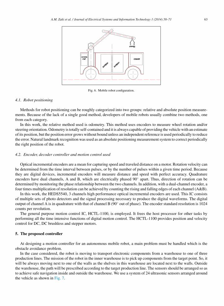
A.M. Zaki et al. / Journal of Electrical Systems and Information Technology 1 (2014) 58–71 63
4
mf
sott
4
btedf
ooc
pc
5
o
pwttt
Fig. 6. Mobile robot configuration.
.1. Robot positioning
Methods for robot positioning can be roughly categorized into two groups: relative and absolute position measure-ents. Because of the lack of a single good method, developers of mobile robots usually combine two methods, one
rom each category.In this work, the relative method used is odometry. This method uses encoders to measure wheel rotation and/or
teering orientation. Odometry is totally self-contained and it is always capable of providing the vehicle with an estimatef its position, but the position error grows without bound unless an independent reference is used periodically to reducehe error. Natural landmark recognition was used as an absolute positioning measurement system to correct periodicallyhe right position of the robot.
.2. Encoder, decoder controller and motion control used
Optical incremental encoders are a mean for capturing speed and traveled distance on a motor. Rotation velocity cane determined from the time interval between pulses, or by the number of pulses within a given time period. Becausehey are digital devices, incremental encoders will measure distance and speed with perfect accuracy. Quadraturencoders have dual channels, A and B, which are electrically phased 90◦ apart. Thus, direction of rotation can beetermined by monitoring the phase relationship between the two channels. In addition, with a dual-channel encoder, aour times multiplication of resolution can be achieved by counting the rising and falling edges of each channel (A&B).
In this work, the HEDS5540, 3 channels high performance optical incremental encoders are used. This IC consistsf multiple sets of photo detectors and the signal processing necessary to produce the digital waveforms. The digitalutput of channel A is in quadrature with that of channel B (90◦ out of phase). The encoder standard resolution is 1024ounts per revolution.
The general purpose motion control IC, HCTL-1100, is employed. It frees the host processor for other tasks byerforming all the time intensive functions of digital motion control. The HCTL-1100 provides position and velocityontrol for DC, DC brushless and stepper motors.
. The proposed controller
At designing a motion controller for an autonomous mobile robot, a main problem must be handled which is thebstacle avoidance problem.
In the case considered, the robot is moving to transport electronic components from a warehouse to one of threeroduction lines. The mission of the robot in the inner warehouse is to pick up components from the target point. So, itill be always moving next to one of the walls as the shelves in this warehouse are located next to the walls. Outside
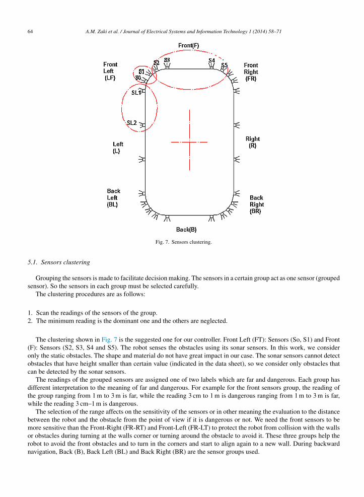
he warehouse, the path will be prescribed according to the target production line. The sensors should be arranged so aso achieve safe navigation inside and outside the warehouse. We use a system of 24 ultrasonic sensors arranged aroundhe vehicle as shown in Fig. 7.
64 A.M. Zaki et al. / Journal of Electrical Systems and Information Technology 1 (2014) 58–71
Fig. 7. Sensors clustering.
5.1. Sensors clustering
Grouping the sensors is made to facilitate decision making. The sensors in a certain group act as one sensor (groupedsensor). So the sensors in each group must be selected carefully.
The clustering procedures are as follows:
1. Scan the readings of the sensors of the group.2. The minimum reading is the dominant one and the others are neglected.
The clustering shown in Fig. 7 is the suggested one for our controller. Front Left (FT): Sensors (So, S1) and Front(F): Sensors (S2, S3, S4 and S5). The robot senses the obstacles using its sonar sensors. In this work, we consideronly the static obstacles. The shape and material do not have great impact in our case. The sonar sensors cannot detectobstacles that have height smaller than certain value (indicated in the data sheet), so we consider only obstacles thatcan be detected by the sonar sensors.
The readings of the grouped sensors are assigned one of two labels which are far and dangerous. Each group hasdifferent interpretation to the meaning of far and dangerous. For example for the front sensors group, the reading ofthe group ranging from 1 m to 3 m is far, while the reading 3 cm to 1 m is dangerous ranging from 1 m to 3 m is far,while the reading 3 cm–1 m is dangerous.
The selection of the range affects on the sensitivity of the sensors or in other meaning the evaluation to the distancebetween the robot and the obstacle from the point of view if it is dangerous or not. We need the front sensors to bemore sensitive than the Front-Right (FR-RT) and Front-Left (FR-LT) to protect the robot from collision with the walls
or obstacles during turning at the walls corner or turning around the obstacle to avoid it. These three groups help therobot to avoid the front obstacles and to turn in the corners and start to align again to a new wall. During backwardnavigation, Back (B), Back Left (BL) and Back Right (BR) are the sensor groups used.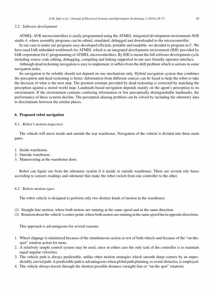
5
s
hIi
n
ttpept
6
6
p
123
a
6
((
1
2
3
4
A.M. Zaki et al. / Journal of Electrical Systems and Information Technology 1 (2014) 58–71 65
.2. Software development
ATMEL AVR microcontrollers is easily programmed using the ATMEL integrated development environment AVRtudio 4, where assembly programs can be edited, simulated, debugged and downloaded to the microcontroller.
In our case to make our programs easy-developed efficient, portable and readable, we decided to program in C. Weave used IAR imbedded workbench for ATMEL which is an integrated development environment (IDE) provided byAR corporation for C-programming of ATMEL microcontrollers. By IDE is meant the full software development cyclencluding source code editing, debugging, compiling and linking supported in one user friendly operator interface.
Although dead reckoning navigation is easy to implement, it suffers from the drift problem which is serious in someavigation tasks.
So navigation to be reliable should not depend on one mechanism only. Hybrid navigation system that combineshe perception and dead reckoning is better. Information from different sources can be fused to help the robot to takehe decision of what is the next step. The position estimate provided by dead reckoning is corrected by matching theerception against a stored world map. Landmark-based navigation depends mainly on the agent’s perception to itsnvironment. If the environment contains confusing information or few perceptually distinguishable landmarks, theerformance of these systems decline. The perceptual aliasing problem can be solved by including the odometry datao discriminate between the similar places.
. Proposed robot navigation
.1. Robot’s motion trajectory
The vehicle will move inside and outside the war warehouse. Navigation of the vehicle is divided into three mainarts:
. Inside warehouse.
. Outside warehouse.
. Maneuvering at the warehouse door.
Robot can figure out from the odometer system if it inside or outside warehouse. There are several rule basesccording to sensors readings and odometer that make the robot switch from one controller to the other.
.2. Robots motion types
The robot vehicle is designed to perform only two distinct kinds of motion in the warehouse:
1) Straight-line motion, where both motors are running at the same speed and in the same direction.2) Rotation about the vehicle’s center-point, where both motors are running at the same speed but in opposite directions.
This approach is advantageous for several reasons:
. Wheel slippage is minimized because of the simultaneous action or rest of both wheels and because of the “on-the-spot” rotation action for turns.
. A relatively simple control system may be used, since in either case the only task of the controller is to maintain
equal angular velocities.. The vehicle path is always predictable, unlike other motion strategies which smooth sharp corners by an unpre-dictably curved path. A predictable path is advantageous when global path planning, to avoid obstacles, is employed.
. The vehicle always travels through the shortest possible distance (straight-line or “on-the spot” rotation).
66 A.M. Zaki et al. / Journal of Electrical Systems and Information Technology 1 (2014) 58–71
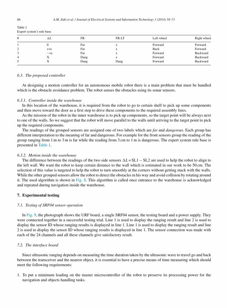
Table 1Expert system’s rule base.
# �L FR FR-LT Left wheel Right wheel
1 0 Far x Forward Forward2 +ve Far x Back Forward3 −ve Far x Forward Backward
4 X Dang x Forward Backward5 X Dang Dang Forward Backward6.3. The proposed controller
At designing a motion controller for an autonomous mobile robot there is a main problem that must be handledwhich is the obstacle avoidance problem. The robot senses the obstacles using its sonar sensors.
6.3.1. Controller inside the warehouseIn this location of the warehouse, it is required from the robot to go to certain shelf to pick up some components
and then move toward the door as a first step to drive these components to the required assembly lines.As the mission of the robot in the inner warehouse is to pick up components, so the target point will be always next
to one of the walls. So we suggest that the robot will move parallel to the walls until arriving to the target point to pickup the required components.
The readings of the grouped sensors are assigned one of two labels which are far and dangerous. Each group hasdifferent interpretation to the meaning of far and dangerous. For example for the front sensors group the reading of thegroup ranging from 1 m to 3 m is far while the reading from 3 cm to 1 m is dangerous. The expert system rule base ispresented in Table 1.
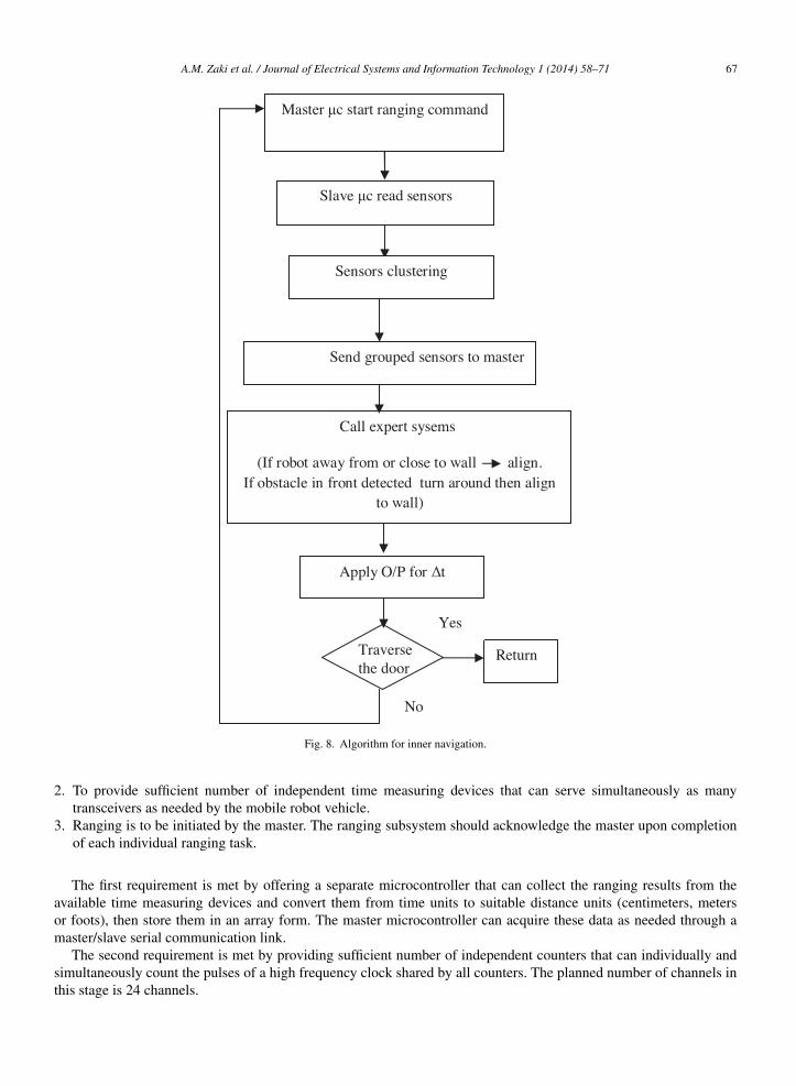
6.3.2. Motion inside the warehouseThe difference between the readings of the two side sensors �L = SL1 − SL2 are used to help the robot to align to
the left wall. We want the robot to keep certain distance to the wall which is estimated in our work to be 50 cm. Theselection of this value is targeted to help the robot to turn smoothly at the corners without getting stuck with the walls.While the other grouped sensors allow the robot to detect the obstacles in his way and avoid collision by rotating aroundit. The used algorithm is shown in Fig. 8. This algorithm is called once entrance to the warehouse is acknowledgedand repeated during navigation inside the warehouse.
7. Experimental testing
7.1. Testing of SRF04 sensor operation
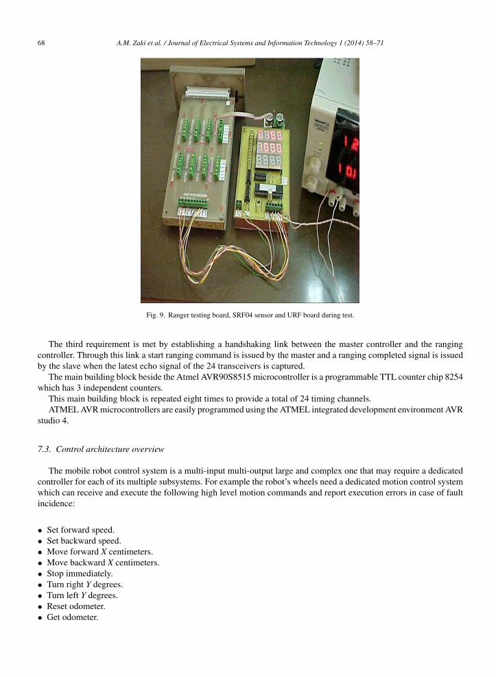
In Fig. 9, the photograph shows the URF board, a single SRF04 sensor, the testing board and a power supply. Theywere connected together in a successful testing trial. Line 1 is used to display the ranging result and line 2 is used todisplay the sensor ID whose ranging results is displayed in line 1. Line 1 is used to display the ranging result and line2 is used to display the sensor ID whose ranging results is displayed in line 1. The sensor connection was made witheach of the 24 channels and all these channels give satisfactory result.
7.2. The interface board
Since ultrasonic ranging depends on measuring the time duration taken by the ultrasonic wave to travel go and backbetween the transceiver and the nearest object, it is essential to have a precise means of time measuring which shouldmeet the following requirements:
1. To put a minimum loading on the master microcontroller of the robot to preserve its processing power for thenavigation and objects handling tasks.
A.M. Zaki et al. / Journal of Electrical Systems and Information Technology 1 (2014) 58–71 67
Master c start rangi ng co mmand
Sla ve c read se nso rs
Sensors cl ustering
Send group ed sensors to ma ster
Call exp ert sysems
(If robot away from or close to wall align.If obstacle in front detected turn arou nd then align
to wall )
Apply O/P for t
Traverse the door
Return
Yes
No
2
3
aom
st
Fig. 8. Algorithm for inner navigation.
. To provide sufficient number of independent time measuring devices that can serve simultaneously as manytransceivers as needed by the mobile robot vehicle.
. Ranging is to be initiated by the master. The ranging subsystem should acknowledge the master upon completionof each individual ranging task.
The first requirement is met by offering a separate microcontroller that can collect the ranging results from thevailable time measuring devices and convert them from time units to suitable distance units (centimeters, metersr foots), then store them in an array form. The master microcontroller can acquire these data as needed through aaster/slave serial communication link.
The second requirement is met by providing sufficient number of independent counters that can individually andimultaneously count the pulses of a high frequency clock shared by all counters. The planned number of channels inhis stage is 24 channels.
68 A.M. Zaki et al. / Journal of Electrical Systems and Information Technology 1 (2014) 58–71
Fig. 9. Ranger testing board, SRF04 sensor and URF board during test.
The third requirement is met by establishing a handshaking link between the master controller and the rangingcontroller. Through this link a start ranging command is issued by the master and a ranging completed signal is issuedby the slave when the latest echo signal of the 24 transceivers is captured.
The main building block beside the Atmel AVR90S8515 microcontroller is a programmable TTL counter chip 8254which has 3 independent counters.
This main building block is repeated eight times to provide a total of 24 timing channels.ATMEL AVR microcontrollers are easily programmed using the ATMEL integrated development environment AVR
studio 4.
7.3. Control architecture overview
The mobile robot control system is a multi-input multi-output large and complex one that may require a dedicatedcontroller for each of its multiple subsystems. For example the robot’s wheels need a dedicated motion control systemwhich can receive and execute the following high level motion commands and report execution errors in case of faultincidence:
• Set forward speed.• Set backward speed.• Move forward X centimeters.• Move backward X centimeters.• Stop immediately.• Turn right Y degrees.
• Turn left Y degrees.• Reset odometer.• Get odometer.
st
nr
7
aAtoi
1234
1234
12345678
T
psa
A.M. Zaki et al. / Journal of Electrical Systems and Information Technology 1 (2014) 58–71 69
This motion control task is accomplished in parallel to the requirements of obstacle avoidance task. So, the controllerystem should be able to accomplish simultaneously the right operation of the robot while taking care of the safety ofhe system.
The ultrasonic ranging subsystem requires a dedicated controller which can accurately report the distances to theearest objects for all the installed ultrasonic sensors in response to a high level “Range Find” command issued by theobot master.
.4. Motion outside the warehouse
Over the outer-warehouse, the robot will move in one of three predetermined paths to arrive to one of the threessembly lines. Each line is assigned a name or a number. These paths were saved in the robot memory, example: –ssembly Line: point Bo then point B1. Each path is saved as a consequence number of (x, y) points starting from just
he warehouse door. So, a look-up table is established to match between the assembly line’s number and the sequencef points representing it. In order that the robot can follow a certain path, it has to trace its points in order until reachingts target. The composite behavior will be divided into four primitive behaviors which are:
Path 1:
. Move forward 1.5 m.
. Turn right 90◦.
. Move forward 6 m.
. Stop.
Path 2:
. Move forward 1.5 m.
. Turn left 90◦.
. Move forward 17 m.
. Stop.
Path 3:
. Move forward 1.5 m.
. Turn left 90◦.
. Move forward 4 m.
. Turn left 90◦.
. Move forward 8 m.
. Turn right 90◦.
. Move forward 17 m.
. Stop
The area of the place was divided as a map of x, y points. Point (0, 0) is just at the midpoint of the warehouse door.he step was set to be 0.5 m.
When the robot terminates the required job at any of the assembly lines, it will take the reverse direction to his
ath returning back to the door of the warehouse (point (0, 0)). During its navigation, the robot reads continuously theensors readings. If the robot detects an obstacle in front of him, it will stop and store its position to avoid the collisionnd at the same time not to lose its path.Look-up table representing the 3 paths will be as follows:
70 A.M. Zaki et al. / Journal of Electrical Systems and Information Technology 1 (2014) 58–71
Assembl yLine2
Assembl yLine3
Assembl yLine1
Warehouse
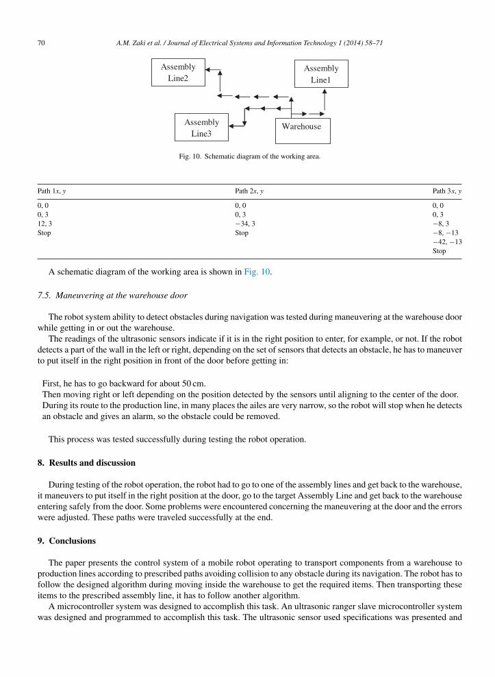
Fig. 10. Schematic diagram of the working area.
Path 1x, y Path 2x, y Path 3x, y
0, 0 0, 0 0, 00, 3 0, 3 0, 312, 3 −34, 3 −8, 3Stop Stop −8, −13
−42, −13Stop
A schematic diagram of the working area is shown in Fig. 10.
7.5. Maneuvering at the warehouse door
The robot system ability to detect obstacles during navigation was tested during maneuvering at the warehouse doorwhile getting in or out the warehouse.
The readings of the ultrasonic sensors indicate if it is in the right position to enter, for example, or not. If the robotdetects a part of the wall in the left or right, depending on the set of sensors that detects an obstacle, he has to maneuverto put itself in the right position in front of the door before getting in:
First, he has to go backward for about 50 cm.Then moving right or left depending on the position detected by the sensors until aligning to the center of the door.During its route to the production line, in many places the ailes are very narrow, so the robot will stop when he detectsan obstacle and gives an alarm, so the obstacle could be removed.
This process was tested successfully during testing the robot operation.
8. Results and discussion
During testing of the robot operation, the robot had to go to one of the assembly lines and get back to the warehouse,it maneuvers to put itself in the right position at the door, go to the target Assembly Line and get back to the warehouseentering safely from the door. Some problems were encountered concerning the maneuvering at the door and the errorswere adjusted. These paths were traveled successfully at the end.
9. Conclusions
The paper presents the control system of a mobile robot operating to transport components from a warehouse toproduction lines according to prescribed paths avoiding collision to any obstacle during its navigation. The robot has tofollow the designed algorithm during moving inside the warehouse to get the required items. Then transporting these
items to the prescribed assembly line, it has to follow another algorithm.A microcontroller system was designed to accomplish this task. An ultrasonic ranger slave microcontroller systemwas designed and programmed to accomplish this task. The ultrasonic sensor used specifications was presented and
A.M. Zaki et al. / Journal of Electrical Systems and Information Technology 1 (2014) 58–71 71
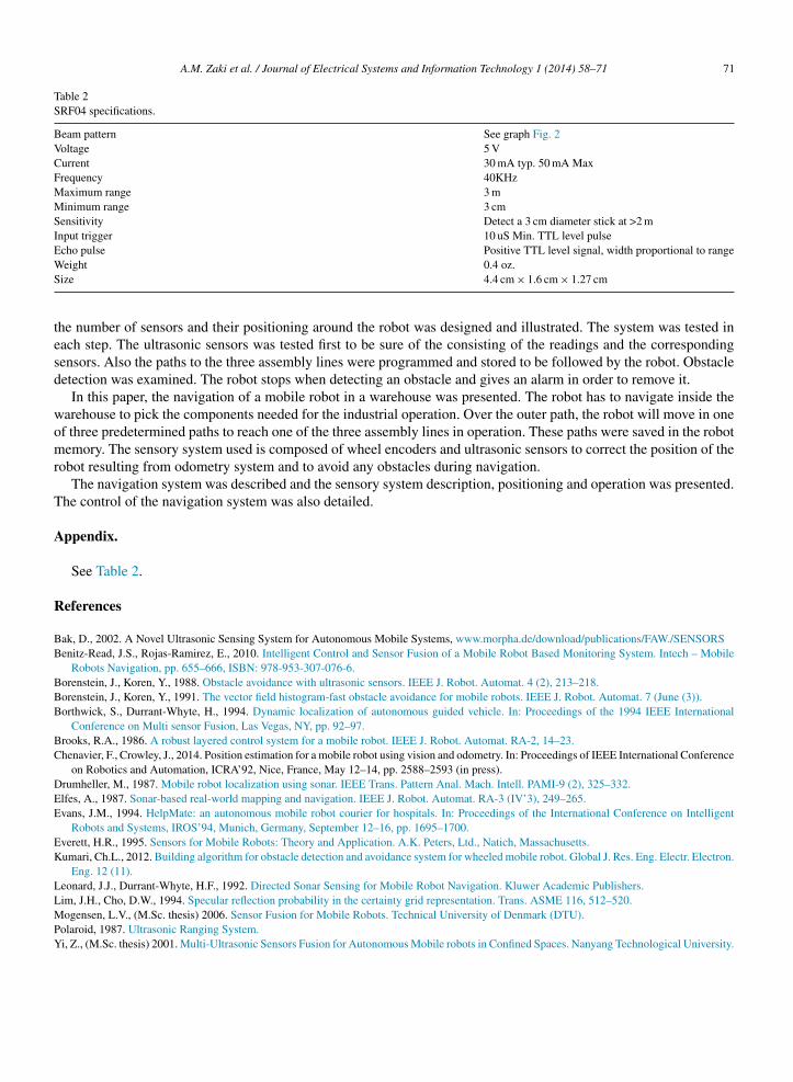
Table 2SRF04 specifications.
Beam pattern See graph Fig. 2Voltage 5 VCurrent 30 mA typ. 50 mA MaxFrequency 40KHzMaximum range 3 mMinimum range 3 cmSensitivity Detect a 3 cm diameter stick at >2 mInput trigger 10 uS Min. TTL level pulseEcho pulse Positive TTL level signal, width proportional to rangeWS
tesd
womr
T
A
R
BB
BBB
BC
DEE
EK
LLMPY
eight 0.4 oz.ize 4.4 cm × 1.6 cm × 1.27 cm
he number of sensors and their positioning around the robot was designed and illustrated. The system was tested inach step. The ultrasonic sensors was tested first to be sure of the consisting of the readings and the correspondingensors. Also the paths to the three assembly lines were programmed and stored to be followed by the robot. Obstacleetection was examined. The robot stops when detecting an obstacle and gives an alarm in order to remove it.
In this paper, the navigation of a mobile robot in a warehouse was presented. The robot has to navigate inside thearehouse to pick the components needed for the industrial operation. Over the outer path, the robot will move in onef three predetermined paths to reach one of the three assembly lines in operation. These paths were saved in the robotemory. The sensory system used is composed of wheel encoders and ultrasonic sensors to correct the position of the
obot resulting from odometry system and to avoid any obstacles during navigation.The navigation system was described and the sensory system description, positioning and operation was presented.
he control of the navigation system was also detailed.
ppendix.
See Table 2.
eferences
ak, D., 2002. A Novel Ultrasonic Sensing System for Autonomous Mobile Systems, www.morpha.de/download/publications/FAW./SENSORSenitz-Read, J.S., Rojas-Ramirez, E., 2010. Intelligent Control and Sensor Fusion of a Mobile Robot Based Monitoring System. Intech – Mobile
Robots Navigation, pp. 655–666, ISBN: 978-953-307-076-6.orenstein, J., Koren, Y., 1988. Obstacle avoidance with ultrasonic sensors. IEEE J. Robot. Automat. 4 (2), 213–218.orenstein, J., Koren, Y., 1991. The vector field histogram-fast obstacle avoidance for mobile robots. IEEE J. Robot. Automat. 7 (June (3)).orthwick, S., Durrant-Whyte, H., 1994. Dynamic localization of autonomous guided vehicle. In: Proceedings of the 1994 IEEE International
Conference on Multi sensor Fusion, Las Vegas, NY, pp. 92–97.rooks, R.A., 1986. A robust layered control system for a mobile robot. IEEE J. Robot. Automat. RA-2, 14–23.henavier, F., Crowley, J., 2014. Position estimation for a mobile robot using vision and odometry. In: Proceedings of IEEE International Conference
on Robotics and Automation, ICRA’92, Nice, France, May 12–14, pp. 2588–2593 (in press).rumheller, M., 1987. Mobile robot localization using sonar. IEEE Trans. Pattern Anal. Mach. Intell. PAMI-9 (2), 325–332.lfes, A., 1987. Sonar-based real-world mapping and navigation. IEEE J. Robot. Automat. RA-3 (IV’3), 249–265.vans, J.M., 1994. HelpMate: an autonomous mobile robot courier for hospitals. In: Proceedings of the International Conference on Intelligent
Robots and Systems, IROS’94, Munich, Germany, September 12–16, pp. 1695–1700.verett, H.R., 1995. Sensors for Mobile Robots: Theory and Application. A.K. Peters, Ltd., Natich, Massachusetts.umari, Ch.L., 2012. Building algorithm for obstacle detection and avoidance system for wheeled mobile robot. Global J. Res. Eng. Electr. Electron.
Eng. 12 (11).eonard, J.J., Durrant-Whyte, H.F., 1992. Directed Sonar Sensing for Mobile Robot Navigation. Kluwer Academic Publishers.
im, J.H., Cho, D.W., 1994. Specular reflection probability in the certainty grid representation. Trans. ASME 116, 512–520.ogensen, L.V., (M.Sc. thesis) 2006. Sensor Fusion for Mobile Robots. Technical University of Denmark (DTU).olaroid, 1987. Ultrasonic Ranging System.i, Z., (M.Sc. thesis) 2001. Multi-Ultrasonic Sensors Fusion for Autonomous Mobile robots in Confined Spaces. Nanyang Technological University.