microchannel heat sinks: an overview of the...
TRANSCRIPT
MTE 8(3) #19972
Microscale Thermophysical Engineering, 8:183–205, 2004Copyright © Taylor & Francis Inc.ISSN: 1089-3954 print/1091-7640 onlineDOI: 10.1080/10893950490477338
MICROCHANNEL HEAT SINKS: AN OVERVIEW OF THESTATE-OF-THE-ART
I. Hassan, P. Phutthavong, and M. AbdelgawadDepartment of Mechanical and Industrial Engineering, Concordia University,Montreal, Quebec, Canada
Computers are rapidly becoming faster and more versatile, and as a result, high-poweredintegrated circuits have been produced in order to meet this need. However, these high-speed circuits are expected to generate heat fluxes that exceed the circuit’s allowableoperating temperature, and so an innovative cooling device is needed to solve this problem.Microchannel heat sinks were introduced in the early 1980s to be used as a means ofcooling integrated circuits. Since then, many studies have been conducted in the field ofthese microchannel heat sinks. Earlier research used mainly single-phase coolants in theirheat sinks, but two-phase coolants are now the focus of more recent research. The purposeof this article is to present a state-of-the art literature review of the progress of research inthe field of microchannel heat sinks. This literature will focus mainly on the most recentresearch, starting with the latter half of the 1990s.
Keywords microchannel heat sinks, integrated circuits cooling, literature review
INTRODUCTION
Today’s electronic components are required to perform tasks at a faster rate, and sohigh-powered integrated circuits have been produced in order to meet this need. Thesehigh-speed circuits are expected to generate heat fluxes that will cause the circuit toexceed its allowable temperature. In order to solve this problem, microchannel heat sinkswere introduced in 1981 by Tuckerman and Pease [1] and have since been the studyof many researchers in the field of fluid mechanics. Microchannel heat sinks functionin a rather simple manner. Multiple microchannels are machined on the back of thesubstrates of electronic components in integrated circuits. The heat generated by theelectronic component is transferred to the coolant by forced convection. The microscopicsize of the channels causes a decrease in the thickness of the thermal boundary layer,which generates a decrease in the convective resistance to heat transfer, thus generatinghigh cooling rates.
In the 1980s, Tuckerman [2] suggested that laminar flow is the best for heat removalthrough microchannels, due to the development of the thin thermal boundary layer. Hedesigned microchannel heat sinks with different dimensions in order to study flow friction
Received 2 November 2002; accepted 1 August 2003.Address correspondence to Dr. I. Hassan, Department of Mechanical and Industrial Engineering, Con-
cordia University, 1455 de Maisonneuve Blvd. West, H-549, Montreal, Quebec H3G IM8, Canada. E-mail:[email protected]
183
184 I. HASSAN ET AL.
NOMENCLATURE
b slip coefficientD microchannel diameter (m)f friction factorh heat transfer coefficient (W/m2 · ◦C)h average heat transfer coefficient
(W/m2 · ◦C)H microchannel height (m)k thermal conductivity (W/m · ◦C)Kn Knudsen number� characteristic length (m)L microchannel length (m)
Nu Nusselt number(= hL
k
)Pr Prandtl numberqw wall heat flux (W/m2)
Re Reynolds number(= ρU�
µ
)T temperature (◦C)U velocity (m/s)wc microchannel width (m)x quality
Z effect of aspect ratio = min(H,L)/max(H,L)
Greek Symbolsλ mean free path of molecules (m)µ dynamic viscosity (Pa · s)ρ density (kg/m3)σ surface tension (N/m)σv tangential momentum accommodation
coefficient
Subscriptsc channelCHF critical heat fluxe thermodynamic equilibriuml along lengthtp two-phasev vaporw wall
and heat transfer within these sinks. He also developed an optimization procedure topredict the best aspect ratio of the channel to achieve the best heat transfer. He usedonly liquid water as a coolant in his experiments. When examining the flow friction,he discovered that head loss was much larger than he anticipated. Also, the value heobtained for the thermal resistance, defined as �T/qw for one-dimensional heat flow,was more than 20 times lower than other cooling devices used for cooling integratedcircuits at the time. Since Tuckerman’s work in the 1980s, many investigations havebeen conducted with the purpose of gaining further understanding of the fluid mechanicswithin microchannel heat sinks. The study of heat transfer and fluid flow in microchannelheat sinks can be divided into two subsections, depending on the phase of the coolantthat flows through them. These are single-phase flow and two-phase flow. The presentliterature review will provide the progress of the study of heat transfer and fluid flow ineach section and will ultimately lead to new future research directions in the field. It willfocus mainly on the recent benchmark research, starting with the latter half of the 1990s.
SINGLE PHASE FLOW
Liquid Phase
Earlier research focused mainly on single-phase liquid flow. In 1998, Poh andNg [3] conducted a numerical analysis of fluid phenomena in microchannel heat sinksusing ANSYS, a CFD package, by simulating flow in a microchannel array. They usedFluorocarbon Liquid FX-3250, which boils at 56◦C. Sixteen different situations werestudied whereby the microchannel width, height, length, the inlet velocity of the coolant,and the wall heat flux were varied. For simplicity, only half the microchannel widthwas considered for their numerical study. The values for half the microchannel width
MICROCHANNEL HEAT SINKS 185
were 0.5wc = 28.3 and 56.6 µm and the microchannel heights used were H = 150and 200 µm. The lengths of the microchannels were L = 400 and 1000 µm and thecoolant velocities utilized were U = 0.1 and 1.0 m/s. The wall heat fluxes imposedon the microchannel heat sink were qw = 2.48 × 10⁵, 3.17 × 10⁵, 4.42 × 10⁵, and5.49 × 105 W/m2. They assumed laminar flow, constant fluid properties and inlet velocity,uniform wall heat flux, as well as zero pressure and zero velocity gradients at the exitof the microchannel. The wall opposite to the isoflux wall was considered adiabatic. Pohand Ng showed that the effect of the microchannel length was slight, where a decrease inlength caused an increase in thermal resistance. Similarly, the thermal resistance increasedwhen decreasing the microchannel depth, increasing the width, and decreasing the inletvelocity. Their numerical results were compared with available analytical results andproved to be in good agreement.
In 1998, Kawano et al. [4] performed both experimental and numerical studiesof pressure drop and heat transfer in microchannel heat sinks. For their experiments,110 microchannels were arranged in a microchannel heat sink of a 15 × 15 mm2 area.Water served as the coolant. The microchannel width was fixed at 57 µm, and the heightused was either 180 or 370 µm, depending on the phenomena under investigation. Fullydeveloped laminar flow was assumed in the numerical simulations. The microchannel heatsink was not heated for the pressure drop measurements. The pressure drop results of theexperiments and simulations were in good agreement with each other for 0 < Re < 200.In this range, the values for the thermal resistances at the entrance of the microchannelvaried by quite a large margin. This discrepancy was attributed to the fact that viscosityof the water is dependent on temperature, and that there is a large temperature gradientat the inlet. For Re > 300 the predicted values of the pressure drop in the simulationwere lower than those obtained in the experiments. The thermal resistance change acrossthe heat sink (from entrance to exit) was approximately 0.1 K/W · cm2, which indicatesthat the temperature difference was about 10 K for a heat flux of 100 W/cm2. Hence,larger heat fluxes may generate enough thermal stress to break the chip if careful designis not performed.
Zeighami et al. [5] studied transition from laminar to turbulent flows for waterin microchannel heat sinks. Previous work indicates that flow transition occurred at atransition Reynolds number lower than 2200, which is the transition Re at the macroscale.Low transition Reynolds numbers could be due to surface roughness, viscous heating,and/or the electric double layer. Until now, analytical work has not been able to determinethe transition Reynolds number at the microscopic level. This transition number can onlybe studied experimentally. Using microresolution particle image velocimetry, Zeighamiet al. generated vector fields in a microchannel measuring 150 µm × 100 µm × 1 cm.Velocity fields at Reynolds numbers of 200, 720, 1200, and 1600 were generated. Exceptfor the case where Re = 1600, all fields seemed steady and parallel. When Re = 1600,the flow began to show some turbulent behavior. The velocity fields temporally fluctuatedand became more asymmetric.
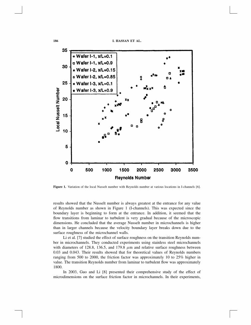
Rahman [6] experimentally determined the pressure drop and heat transfer in twodifferent geometries of microchannel heat sinks. The two configurations are I-channels,where the working fluid flows through parallel channels, and U-channels, where the fluidpasses through numerous bends in a single channel. The width of the individual channelswas 1 mm and the depths ranged from 176 to 278 µm. Using water as the coolant, hemeasured the pressure and temperature of the coolant along the microchannel. Rahman’s
186 I. HASSAN ET AL.
Figure 1. Variation of the local Nusselt number with Reynolds number at various locations in I-channels [6].
results showed that the Nusselt number is always greatest at the entrance for any valueof Reynolds number as shown in Figure 1 (I-channels). This was expected since theboundary layer is beginning to form at the entrance. In addition, it seemed that theflow transitions from laminar to turbulent is very gradual because of the microscopicdimensions. He concluded that the average Nusselt number in microchannels is higherthan in larger channels because the velocity boundary layer breaks down due to thesurface roughness of the microchannel walls.
Li et al. [7] studied the effect of surface roughness on the transition Reynolds num-ber in microchannels. They conducted experiments using stainless steel microchannelswith diameters of 128.8, 136.5, and 179.8 µm and relative surface roughness between0.03 and 0.043. Their results showed that for theoretical values of Reynolds numbersranging from 500 to 2000, the friction factor was approximately 10 to 25% higher invalue. The transition Reynolds number from laminar to turbulent flow was approximately1800.
In 2003, Guo and Li [8] presented their comprehensive study of the effect ofmicrodimensions on the surface friction factor in microchannels. In their experiments,
MICROCHANNEL HEAT SINKS 187
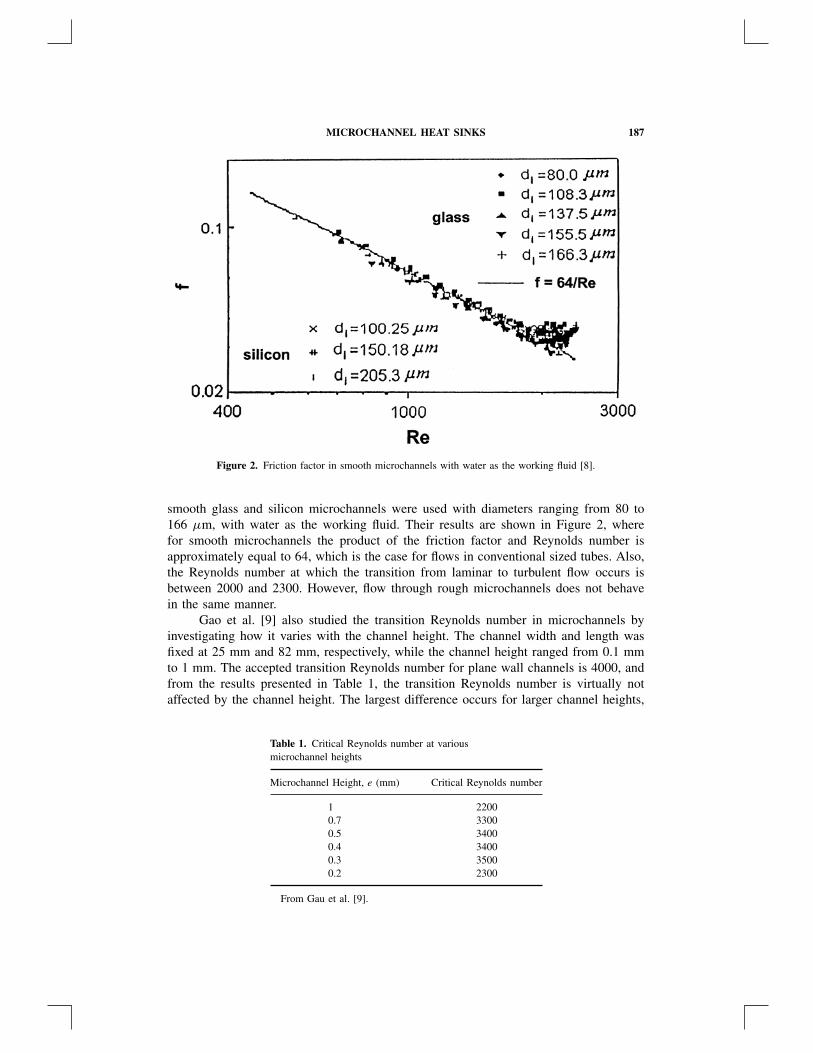
Figure 2. Friction factor in smooth microchannels with water as the working fluid [8].
smooth glass and silicon microchannels were used with diameters ranging from 80 to166 µm, with water as the working fluid. Their results are shown in Figure 2, wherefor smooth microchannels the product of the friction factor and Reynolds number isapproximately equal to 64, which is the case for flows in conventional sized tubes. Also,the Reynolds number at which the transition from laminar to turbulent flow occurs isbetween 2000 and 2300. However, flow through rough microchannels does not behavein the same manner.
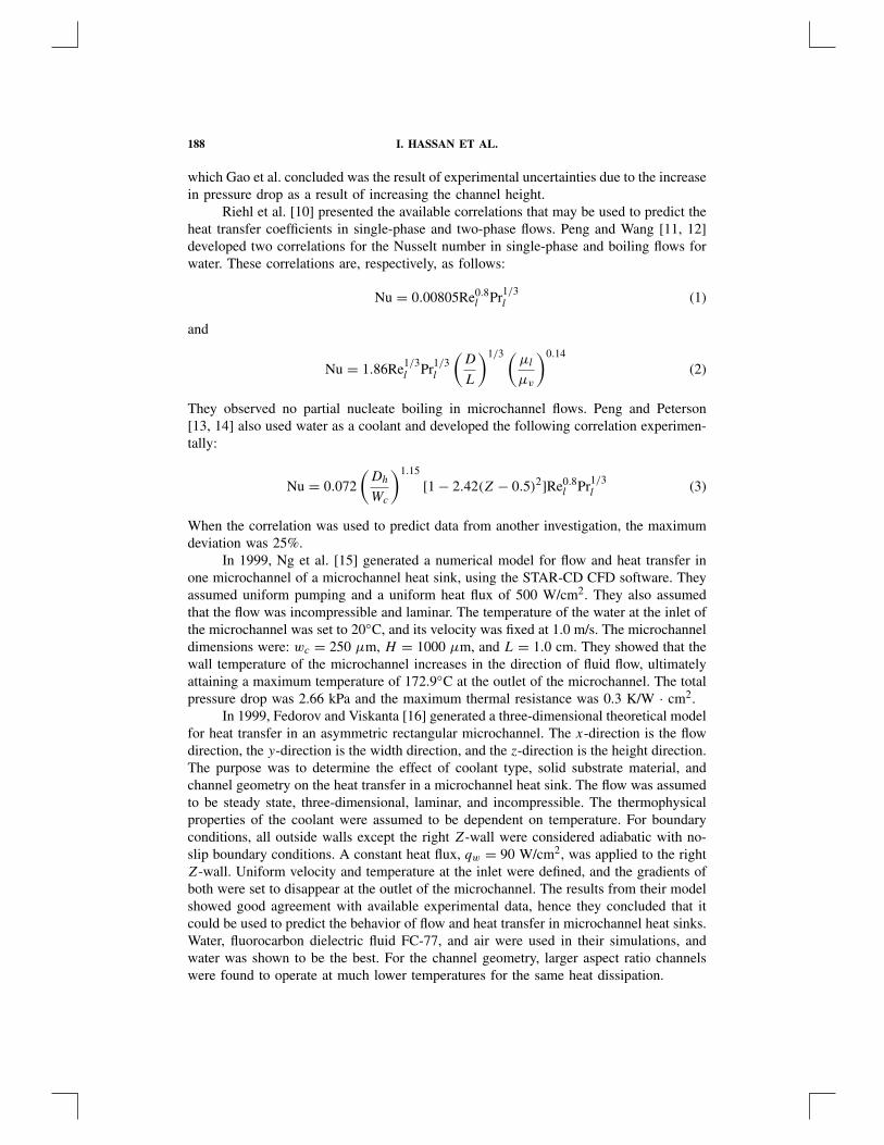
Gao et al. [9] also studied the transition Reynolds number in microchannels byinvestigating how it varies with the channel height. The channel width and length wasfixed at 25 mm and 82 mm, respectively, while the channel height ranged from 0.1 mmto 1 mm. The accepted transition Reynolds number for plane wall channels is 4000, andfrom the results presented in Table 1, the transition Reynolds number is virtually notaffected by the channel height. The largest difference occurs for larger channel heights,
Table 1. Critical Reynolds number at variousmicrochannel heights
Microchannel Height, e (mm) Critical Reynolds number
1 22000.7 33000.5 34000.4 34000.3 35000.2 2300
From Gau et al. [9].
188 I. HASSAN ET AL.
which Gao et al. concluded was the result of experimental uncertainties due to the increasein pressure drop as a result of increasing the channel height.
Riehl et al. [10] presented the available correlations that may be used to predict theheat transfer coefficients in single-phase and two-phase flows. Peng and Wang [11, 12]developed two correlations for the Nusselt number in single-phase and boiling flows forwater. These correlations are, respectively, as follows:
Nu = 0.00805Re0.8l Pr1/3
l (1)
and
Nu = 1.86Re1/3l Pr1/3
l
(D
L
)1/3 (µl
µv
)0.14
(2)
They observed no partial nucleate boiling in microchannel flows. Peng and Peterson[13, 14] also used water as a coolant and developed the following correlation experimen-tally:
Nu = 0.072
(Dh
Wc
)1.15
[1 − 2.42(Z − 0.5)2]Re0.8l Pr1/3
l (3)
When the correlation was used to predict data from another investigation, the maximumdeviation was 25%.
In 1999, Ng et al. [15] generated a numerical model for flow and heat transfer inone microchannel of a microchannel heat sink, using the STAR-CD CFD software. Theyassumed uniform pumping and a uniform heat flux of 500 W/cm2. They also assumedthat the flow was incompressible and laminar. The temperature of the water at the inlet ofthe microchannel was set to 20◦C, and its velocity was fixed at 1.0 m/s. The microchanneldimensions were: wc = 250 µm, H = 1000 µm, and L = 1.0 cm. They showed that thewall temperature of the microchannel increases in the direction of fluid flow, ultimatelyattaining a maximum temperature of 172.9◦C at the outlet of the microchannel. The totalpressure drop was 2.66 kPa and the maximum thermal resistance was 0.3 K/W · cm2.
In 1999, Fedorov and Viskanta [16] generated a three-dimensional theoretical modelfor heat transfer in an asymmetric rectangular microchannel. The x-direction is the flowdirection, the y-direction is the width direction, and the z-direction is the height direction.The purpose was to determine the effect of coolant type, solid substrate material, andchannel geometry on the heat transfer in a microchannel heat sink. The flow was assumedto be steady state, three-dimensional, laminar, and incompressible. The thermophysicalproperties of the coolant were assumed to be dependent on temperature. For boundaryconditions, all outside walls except the right Z-wall were considered adiabatic with no-slip boundary conditions. A constant heat flux, qw = 90 W/cm2, was applied to the rightZ-wall. Uniform velocity and temperature at the inlet were defined, and the gradients ofboth were set to disappear at the outlet of the microchannel. The results from their modelshowed good agreement with available experimental data, hence they concluded that itcould be used to predict the behavior of flow and heat transfer in microchannel heat sinks.Water, fluorocarbon dielectric fluid FC-77, and air were used in their simulations, andwater was shown to be the best. For the channel geometry, larger aspect ratio channelswere found to operate at much lower temperatures for the same heat dissipation.
MICROCHANNEL HEAT SINKS 189
Fedorov and Viskanta continued their work a year later [17]. Using the sameassumptions and physical model as they did in the study mentioned above, they studiedsubsequent three-dimensional heat transfer in an asymmetric rectangular channel whenthe right Z-wall is heated. Their analyses concluded that the heat introduced at the rightZ-wall is transferred to the remaining channel walls through conduction, moving in theupstream direction toward the inlet of the microchannel. Heat transfer to the coolant is atits maximum at the inlet since there is minimum convective resistance. Due to the smallerspacing between the two Y -walls, the heat flux at these walls is two orders of magnitudehigher than that at the Z-walls. At the corners of the microchannels the boundary layersinteract and produce competition between two local thermal resistances: one for the heattransfer of one wall to the bulk fluid, and the other for the heat transfer between thetwo adjacent walls via the corner boundary layers. The heat will be conducted throughadjacent walls, rather than being convected to the bulk fluid because the conductionthermal resistance is smaller than that produced by heat transfer through convection.As a result, the heat from the Z-wall passes through the fluid and meets the adjacentY -wall, producing heat vortices at the corners of the microchannel. Thus, the heat transfercoefficient is an inadequate parameter to define heat transfer in conjugate problems.
Perret et al. [18] developed an optimization model that could be used to deter-mine the best parameters suited for microchannel heat sinks. Water was chosen as thecoolant because of its high specific heat capacity, which in turn minimizes capacitiveresistance. They generated analytical models to determine relationships between the ther-mal resistance of the heat sink and the heat sink’s dimensions. The dimensions of themicrochannel heat sinks were varied such that the value of the heat transfer coefficient,in the analytical models they produced, was optimized. This was accomplished by usinga home-developed software entitled Pascosma. Perret et al. indicated that fabrication ofthe optimized microchannel heat sink is still ongoing. Thus, experimental work needs tobe conducted on the optimized heat sink to determine whether it really yields the bestperformance.
Gas Phase
In conventional sized channels, gas flow is assumed to be incompressible as longas the Mach number is much smaller than unity. However, at the microscale level, asreported by Guo and Wu [19, 20] there is significant variation in the density of gases dueto the large pressure drops resulting from the surface friction inside the microchannels.Most studies of heat transfer and fluid flow in microchannel heat sinks use liquid coolants,as opposed to gaseous coolants. However, there are some studies that utilized gaseouscoolants, such as air, and a summary of recent investigations is presented below.
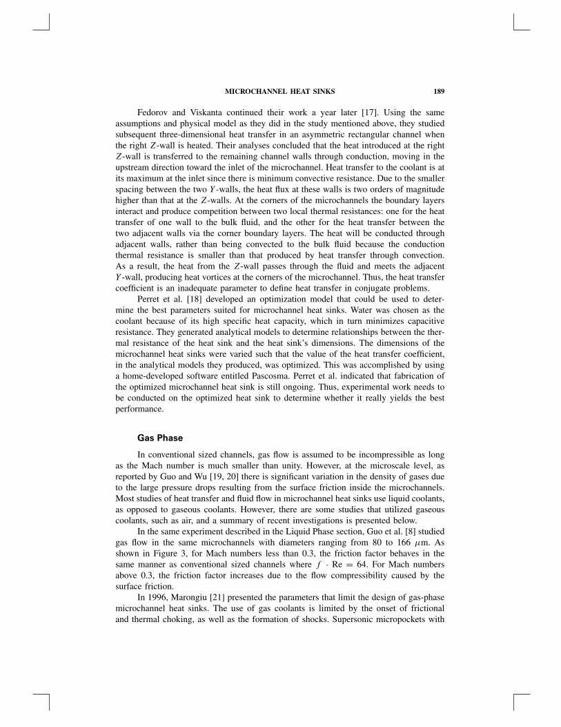
In the same experiment described in the Liquid Phase section, Guo et al. [8] studiedgas flow in the same microchannels with diameters ranging from 80 to 166 µm. Asshown in Figure 3, for Mach numbers less than 0.3, the friction factor behaves in thesame manner as conventional sized channels where f · Re = 64. For Mach numbersabove 0.3, the friction factor increases due to the flow compressibility caused by thesurface friction.
In 1996, Marongiu [21] presented the parameters that limit the design of gas-phasemicrochannel heat sinks. The use of gas coolants is limited by the onset of frictionaland thermal choking, as well as the formation of shocks. Supersonic micropockets with
190 I. HASSAN ET AL.
Figure 3. Variation of friction factor with Mach number for gas flow in smooth microchannels [8].
shock waves need to be evaded to avoid increasing pumping power and damaging thechannel. Also, Mach number will inevitably increase because of friction and heat addition;therefore compressibility effects must be considered. Now, sonic flow will occur at acertain length of the microchannel. As the length of the channel is increased, the flowrate will decrease, reducing the cooling performance of the sink. In addition, excessivepressure drops must be avoided to circumvent choking. Moreover, there is a maximumquantity of heat that a gas-cooled microchannel heat sink may dissipate because heataddition could render the flow sonic at the outlet. Finally, it is important not to includetoo many microchannels for gas coolants, because the heat transfer decreases for a givenvolumetric flow rate as the number of channels increases.
In 1998, Marongiu et al. [22] designed a board composed of channels throughwhich air flows at speeds greater than 50 m/s. The board had a length of 0.15 m, aheight of 0.025 m, and a width of 0.1 m. All the channels were 2 mm thick. Theefficiency of the heat sink was determined by measuring the degree of irreversibilitiesby obtaining the local stagnation pressure. Results showed that heat removal rates aregreater at higher speeds. However, choking occurred at some point in the apparatus atair speeds of approximately 50 m/s.
It is important to consider the flow regime, velocity slip, and temperature jumpboundary conditions when dealing with gaseous flow in microchannels. The Knudsennumber, Kn = λ
�, determines the flow regime; these flow regimes are the continuum flow
regime, slip flow regime, transition flow regime, and free-molecular flow regime. Theflow equations and boundary conditions that may be applied for a certain flow dependson its flow regime. Beskok and Karniadakis [23, 24] developed a unified model to predictthe mass flow rate and pressure distribution in channels, pipes, and ducts for Knudsennumbers, Kn, ranging from zero to infinity. A new second-order general velocity slip
MICROCHANNEL HEAT SINKS 191
boundary condition was introduced in order to develop this model. They compared theirnew model with existing results obtained though DSMC (Direct Simulation Monte Carlo)simulations, linear Boltzmann solutions, and experimental data.
The general velocity slip boundary condition predicts the amount of velocity slipin channels for all flow regimes as follows:
U − Uw = 2 − σv
σv
[Kn
1 − bKn
(∂U
∂n
)](4)
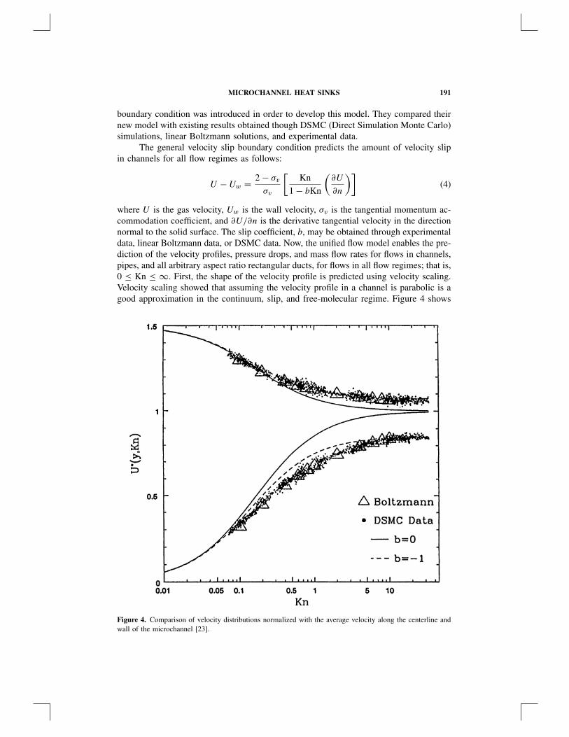
where U is the gas velocity, Uw is the wall velocity, σv is the tangential momentum ac-commodation coefficient, and ∂U/∂n is the derivative tangential velocity in the directionnormal to the solid surface. The slip coefficient, b, may be obtained through experimentaldata, linear Boltzmann data, or DSMC data. Now, the unified flow model enables the pre-diction of the velocity profiles, pressure drops, and mass flow rates for flows in channels,pipes, and all arbitrary aspect ratio rectangular ducts, for flows in all flow regimes; that is,0 ≤ Kn ≤ ∞. First, the shape of the velocity profile is predicted using velocity scaling.Velocity scaling showed that assuming the velocity profile in a channel is parabolic is agood approximation in the continuum, slip, and free-molecular regime. Figure 4 shows
Figure 4. Comparison of velocity distributions normalized with the average velocity along the centerline andwall of the microchannel [23].
192 I. HASSAN ET AL.
the nondimensionalized velocity distribution at the wall and along the centerline of themicrochannel for 0.01 ≤ Kn ≤ 30. It can be seen that Maxwell’s first-order boundarycondition (b = 0) is erroneous for large Knudsen numbers, where it predicts a uniformvelocity distribution. The slip flow theory breaks down for Kn = 0.1 for the wall veloc-ity and for Kn = 0.4 for the centerline velocity, and so accounts for this error. For thesecond-order boundary condition (b = −1), the model slightly overpredicts the DSMCdata for 0.1 ≤ Kn ≤ 5, and this is mostly likely due to the effect of the Knudsen layer.Thus, in the transition flow regime there are some slight deviations due to the develop-ment of the Knudsen layer. Next, the actual magnitude of the average velocity, and thusthe volume flow rate, are obtained through flow rate scaling. The model was validated bycomparing their results with existing DSMC data in the slip/early transition regimes. Asrarefaction increases, the curvature in the pressure distribution decreases until it becomesalmost linear.
In 1996, Baker and Calvert [25] conducted a numerical study on the temperature-dependent nature of viscosity on microchannel flows to study the effect of fluid propertyvariation on heat sink performance. Poiseuille flow and linear pressure gradients were as-sumed, and velocity and temperature were considered to vary only in the lateral direction.Sutherland’s model for dynamic viscosity was used, along with the coupled momentumand energy equations. Maxwell’s velocity slip boundary condition and Smoluchowski’stemperature jump boundary conditions were applied at the solid-fluid interface. Higher-order terms were neglected for the numerical and analytical models. When incorporatingvariable viscosity, the numerical results in Baker and Calvert’s work showed significantdifferences from the analytical results. More particularly, the variable viscosity modelgenerally yielded results for the temperature distribution, skin friction coefficients, andStanton numbers that were lower in value compared to the analytical models, although thedifference was quite small for the skin friction coefficients. When the Knudsen numbersincreased, the velocity and temperature profiles showed no qualitative difference, and theskin friction coefficients and Stanton numbers increased accordingly as well. In addition,increasing certain parameters sometimes yielded nonphysical values in the analytical andnumerical models. Thus, higher-order terms must be integrated into both the analyticaland numerical models in order to avoid this situation.
TWO-PHASE FLOW
Single-phase flow in microchannel heat sinks requires either high flow rates orsmaller hydraulic diameters, consequently resulting in larger pressure drops. Therefore,two-phase microchannel heat sinks are an alternative to single-phase microchannel heatsinks because latent heat can be used to maintain the sink at a uniform temperature
In 1999, Jiang et al. [26] investigated the effect of forced convection boiling onthe performance of four different microchannel heat sinks, all with different dimensionsless than 100 µm. In all cases, the onset of critical heat flux was determined to studythe effect of boiling. DI water was used as the coolant. Qualitatively, it appears thatfor the smaller sink the temperature increases and then slowly decreases. The oppositeoccurs for the larger microchannel heat sinks where the temperature decreases initiallyand then increases. They observed the critical heat flux (CHF) while varying the flow rateof the coolant. Their results showed an almost linear relation for the smaller heat sinkswith 40 µm hydraulic diameter channels, where the CHF temperature increases with
MICROCHANNEL HEAT SINKS 193
increasing with flow-rate. However, the CHF temperature did not appear to vary withflow rate or number of channels for the sinks with 80 µm hydraulic diameter channels,even though inlet pressure increases as the flow rate increases. In addition, no boilingplateau was observed in the boiling curves.
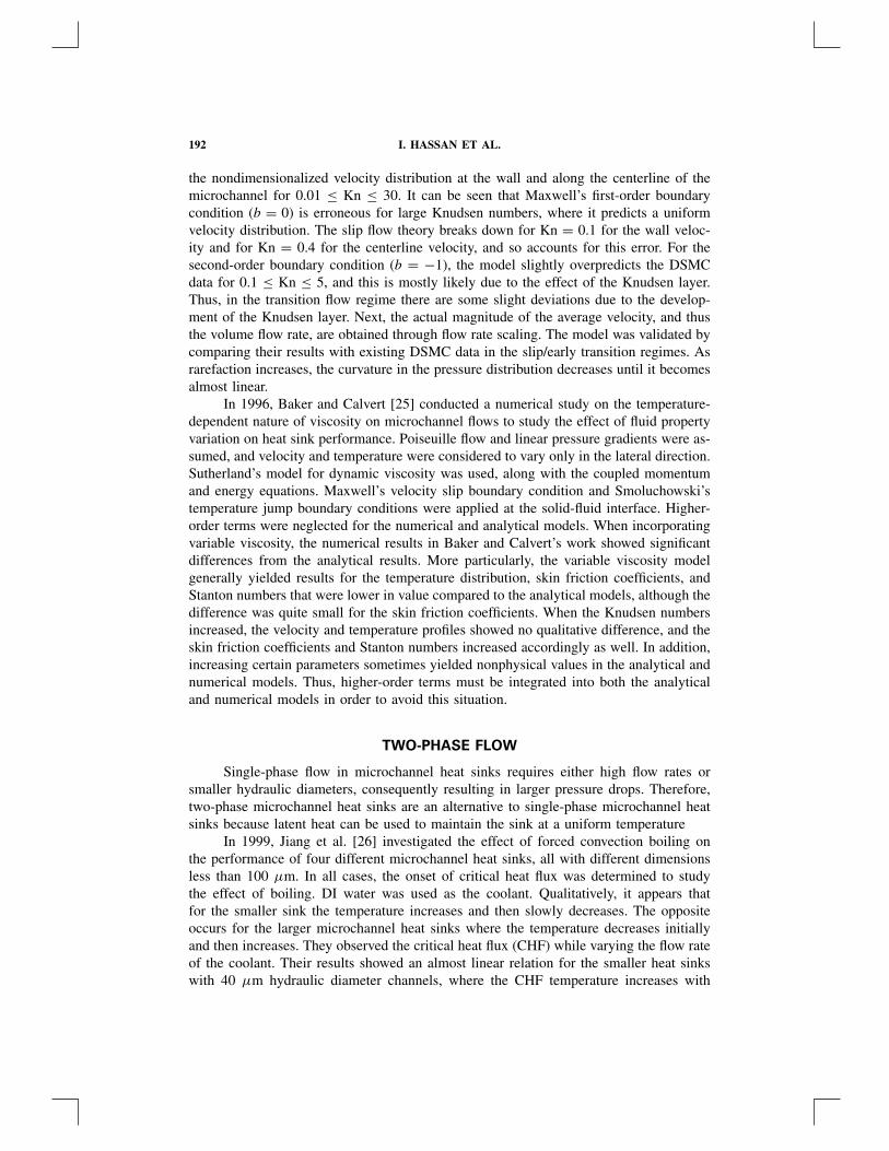
In a later study, Jiang et al. [27] used transparent microchannel heat sinks to observethe flow pattern of the coolant in order to better understand the boiling process. DI waterwas once again used in their investigations. The hydraulic diameters of the triangularmicrochannels were 26 µm and 53 µm. Three zones were observed in the boiling curve,and there was no boiling plateau as shown in Figure 5. Zone I was associated with lowpower input to heat sink, q/qCHF < 0.4, where the flow was single-phase liquid fromthe entrance to the exit of the sink. Local nucleation boiling was observed in this zonebut produced negligible differences in the boiling curve. Zone II corresponds to moderateinput power, 0.4 < q/qCHF < 0.6, bubbles larger than the channel’s dimensions wereformed at the device’s common entrance. The bubbles entered the channel only when thepressure was high enough, and thus exited at very high speeds. At the critical value ofq/qCHF = 0.6, there is annular flow and the flow is unstable due to the random appear-ances of liquid droplets inside the vapor core. For high input power, 0.6 < q/qCHF < 0.9,the annular flow becomes stable. A thin film of liquid lined the walls of the mi-crochannels as well as the exterior of the vapor core. Heat transfer was most activeat the liquid film-vapor core interface. When approaching CHF conditions, q/qCHF = 1,the liquid film totally evaporates, implying that the temperature of the sink increasedabruptly, rendering it impossible to continue inputting power beyond the CHF conditions.
Figure 5. Boiling curve for microchannels [27].
194 I. HASSAN ET AL.
Koo et al. [28] studied, theoretically, two-phase microchannel heat sinks where thehydraulic diameters of the microchannels were less than 100 µm. The wall thicknesswas fixed at 100 µm, and the channel width and depth were varied between 50 and250 µm. The flow was divided into four sections. In Section A, the coolant at the inletis single-phase liquid. Section B is called the flow eruption regime where the coolantundergoes extremely rapid phase change. The flow in this regime is very unstable, suchthat the vapor onset point oscillates erratically in the longitudinal direction. No transitionflow regimes, such as bubbly and plug-flow were observed; thus, Section C is an annularflow regime. Section D exists when the channel is of adequate length and there exist highrates of heat absorption within the microchannel. Complete dryout of the liquid occursin Section D, and so it is composed entirely of vapor. The erratic behaviors of the flowin Section B, as well as the velocity of the thin film of liquid in Section C, are neglected.Using the finite volume method, Koo et al. solved the energy equations and comparedtheir results to available experimental data. The pressure drop predictions were in goodagreement. When the coolant is liquid, the pressure drop decreases as the input power isincreased. However, at the onset of two-phase flow, the pressure drop rises quickly as theheating rate rises. As the dimensions of the microchannels increase, the pressure dropdecreases. It seems smaller dimensions yield a higher heat transfer coefficient; however,the pressure drop will significantly increase for these smaller dimensions, causing asubsequent increase in the saturation temperature at the onset of two-phase flow.
Zhang et al. [29] studied two-phase forced convective flow in microchannels withhydraulic diameters ranging between 25 and 60 µm. Two devices were fabricated forthis study. Device 1 is a multichannel device with 40 channels, and device 2 is a singlechannel device. DI water is used as the working fluid, and is pumped though the devicesat 0.1 ml/min. To account for two-phase flow, a phase change simulation was developed.The simulation considered one-dimensional flow and heat transfer, and its results werecompared with the experimental data obtained in this study. The simulation utilized thefinite volume method and considers fluid properties that are temperature and pressuredependent. In the single-phase region for device 1, the pressure decreases as the heatpower is raised, which is indicative of the lowering of the liquid viscosity due to theincreasing temperature. At the onset of boiling, there is acceleration in the local volumeflow rate since the density of the vapor is very low compared to that of water. As a result,there is a large pressure drop across the channel. The plot of wall temperature versus heatpower shows that the wall temperature decreases slightly at the onset of boiling. Zhanget al. attribute this to nucleation, bubble departure, and possibly pressure fluctuations.
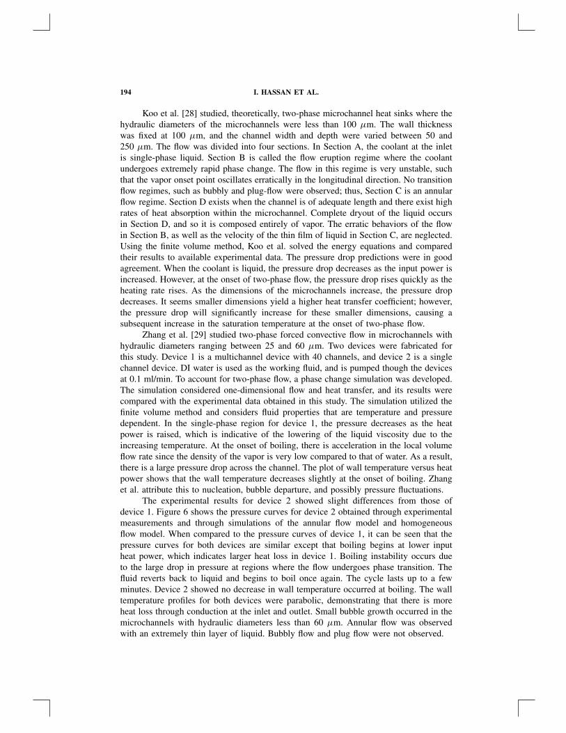
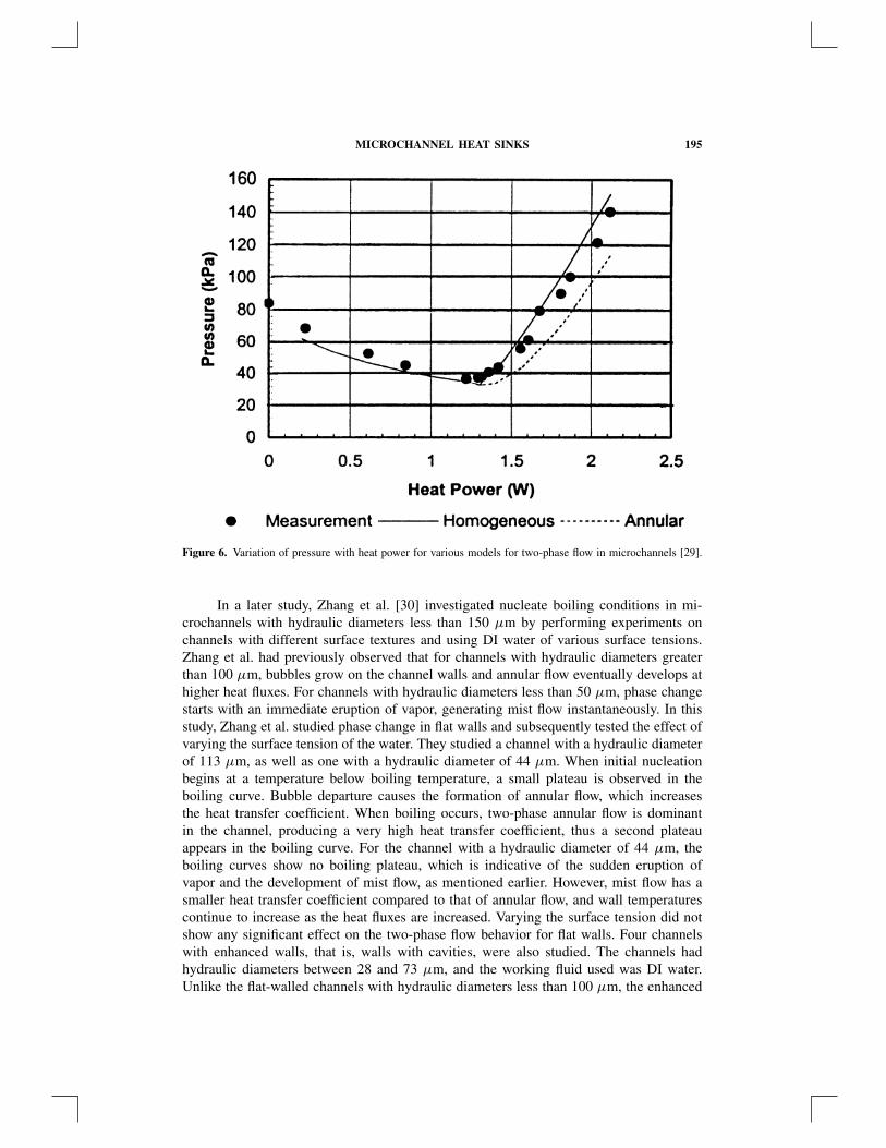
The experimental results for device 2 showed slight differences from those ofdevice 1. Figure 6 shows the pressure curves for device 2 obtained through experimentalmeasurements and through simulations of the annular flow model and homogeneousflow model. When compared to the pressure curves of device 1, it can be seen that thepressure curves for both devices are similar except that boiling begins at lower inputheat power, which indicates larger heat loss in device 1. Boiling instability occurs dueto the large drop in pressure at regions where the flow undergoes phase transition. Thefluid reverts back to liquid and begins to boil once again. The cycle lasts up to a fewminutes. Device 2 showed no decrease in wall temperature occurred at boiling. The walltemperature profiles for both devices were parabolic, demonstrating that there is moreheat loss through conduction at the inlet and outlet. Small bubble growth occurred in themicrochannels with hydraulic diameters less than 60 µm. Annular flow was observedwith an extremely thin layer of liquid. Bubbly flow and plug flow were not observed.
MICROCHANNEL HEAT SINKS 195
Figure 6. Variation of pressure with heat power for various models for two-phase flow in microchannels [29].
In a later study, Zhang et al. [30] investigated nucleate boiling conditions in mi-crochannels with hydraulic diameters less than 150 µm by performing experiments onchannels with different surface textures and using DI water of various surface tensions.Zhang et al. had previously observed that for channels with hydraulic diameters greaterthan 100 µm, bubbles grow on the channel walls and annular flow eventually develops athigher heat fluxes. For channels with hydraulic diameters less than 50 µm, phase changestarts with an immediate eruption of vapor, generating mist flow instantaneously. In thisstudy, Zhang et al. studied phase change in flat walls and subsequently tested the effect ofvarying the surface tension of the water. They studied a channel with a hydraulic diameterof 113 µm, as well as one with a hydraulic diameter of 44 µm. When initial nucleationbegins at a temperature below boiling temperature, a small plateau is observed in theboiling curve. Bubble departure causes the formation of annular flow, which increasesthe heat transfer coefficient. When boiling occurs, two-phase annular flow is dominantin the channel, producing a very high heat transfer coefficient, thus a second plateauappears in the boiling curve. For the channel with a hydraulic diameter of 44 µm, theboiling curves show no boiling plateau, which is indicative of the sudden eruption ofvapor and the development of mist flow, as mentioned earlier. However, mist flow has asmaller heat transfer coefficient compared to that of annular flow, and wall temperaturescontinue to increase as the heat fluxes are increased. Varying the surface tension did notshow any significant effect on the two-phase flow behavior for flat walls. Four channelswith enhanced walls, that is, walls with cavities, were also studied. The channels hadhydraulic diameters between 28 and 73 µm, and the working fluid used was DI water.Unlike the flat-walled channels with hydraulic diameters less than 100 µm, the enhanced
196 I. HASSAN ET AL.
wall channels did show the development of annular flow, since the cavities at the bottomof the channels caused the appearance of bubbles by trapping the gas.
Hestroni et al. [31] investigated the performance of a two-phase microchannelheat sink by attempting to maintain the operating temperature low at temperatures rang-ing from 323 to 333 K. The coolant used was the dielectric liquid DuPont Vertrel XF(dihydrodecafluoropentane C5H2F10). The heat sink was composed of isosceles trian-gle microchannels with hydraulic diameters of 130 µm and a base angle of 55◦. Thethermal pattern of the heated surface of the sink showed a more uniform temperaturedistribution when compared to liquid water microchannel heat sinks. They observed thatincreasing the coolant flow rate increases the input wall heat flux, as well as the heattransfer coefficient. However, at the same mass velocity, the heat transfer coefficient isreduced when the heat flux and the vapor quality increase provided that x is small. Thelargest difference in surface temperature with Vertrel XF was 4–5 K, compared to 20 Kfor single-phase water. For water, 2.5 times the mass flow rate of Vertrel XF is requiredto achieve the same temperature difference of 5 K. Flow instabilities were observed andwere attributed to variations in the pressure drop and a reduction in the heat transfer co-efficient. Temperature fluctuations were also detected and were credited to the pressuredrop fluctuations. Hestroni et al. attributed the fluctuations to the formation of vapor. Asthe heat flux increases, the vapor quality also rises, and so the amplitudes of the pressureand temperature fluctuations increase as well. For single-phase flow, the pressure dropincreases slightly with increasing temperature. However, when the maximum device tem-perature exceeds the saturation temperature of the coolant, two-phase flow occurs, andthe pressure drop rises accordingly.
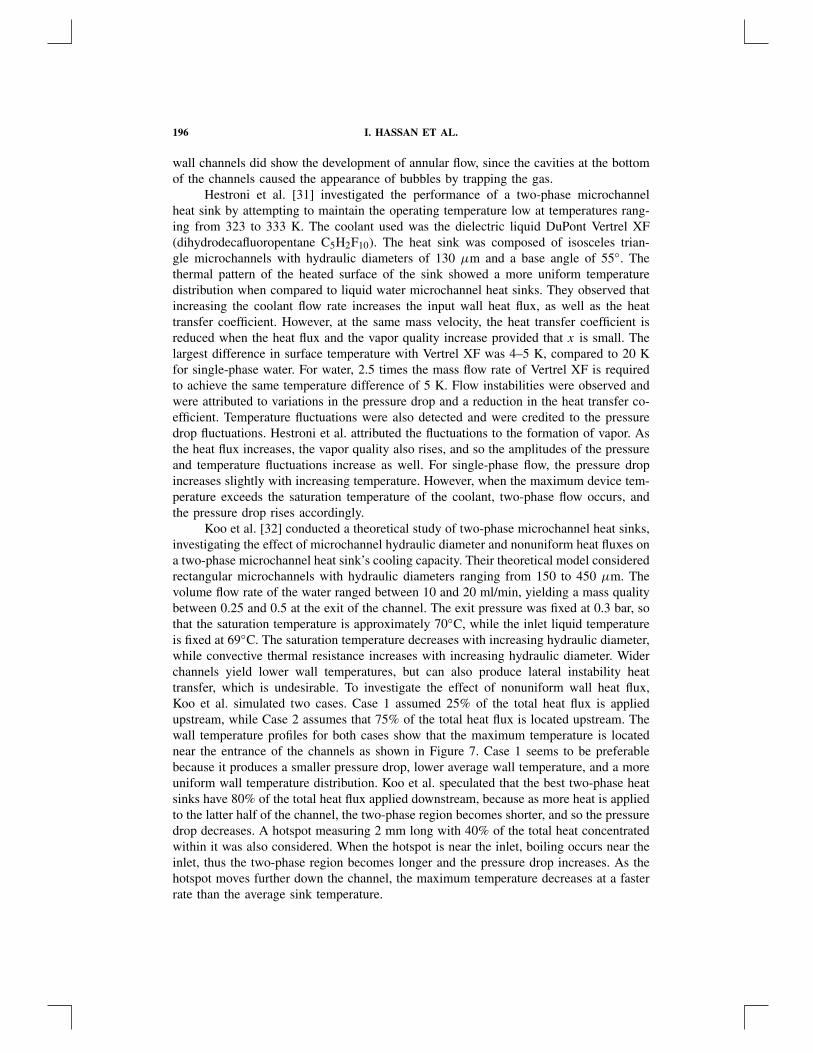
Koo et al. [32] conducted a theoretical study of two-phase microchannel heat sinks,investigating the effect of microchannel hydraulic diameter and nonuniform heat fluxes ona two-phase microchannel heat sink’s cooling capacity. Their theoretical model consideredrectangular microchannels with hydraulic diameters ranging from 150 to 450 µm. Thevolume flow rate of the water ranged between 10 and 20 ml/min, yielding a mass qualitybetween 0.25 and 0.5 at the exit of the channel. The exit pressure was fixed at 0.3 bar, sothat the saturation temperature is approximately 70◦C, while the inlet liquid temperatureis fixed at 69◦C. The saturation temperature decreases with increasing hydraulic diameter,while convective thermal resistance increases with increasing hydraulic diameter. Widerchannels yield lower wall temperatures, but can also produce lateral instability heattransfer, which is undesirable. To investigate the effect of nonuniform wall heat flux,Koo et al. simulated two cases. Case 1 assumed 25% of the total heat flux is appliedupstream, while Case 2 assumes that 75% of the total heat flux is located upstream. Thewall temperature profiles for both cases show that the maximum temperature is locatednear the entrance of the channels as shown in Figure 7. Case 1 seems to be preferablebecause it produces a smaller pressure drop, lower average wall temperature, and a moreuniform wall temperature distribution. Koo et al. speculated that the best two-phase heatsinks have 80% of the total heat flux applied downstream, because as more heat is appliedto the latter half of the channel, the two-phase region becomes shorter, and so the pressuredrop decreases. A hotspot measuring 2 mm long with 40% of the total heat concentratedwithin it was also considered. When the hotspot is near the inlet, boiling occurs near theinlet, thus the two-phase region becomes longer and the pressure drop increases. As thehotspot moves further down the channel, the maximum temperature decreases at a fasterrate than the average sink temperature.
MICROCHANNEL HEAT SINKS 197
Figure 7. Wall temperature distribution for nonuniform wall heat fluxes [32].
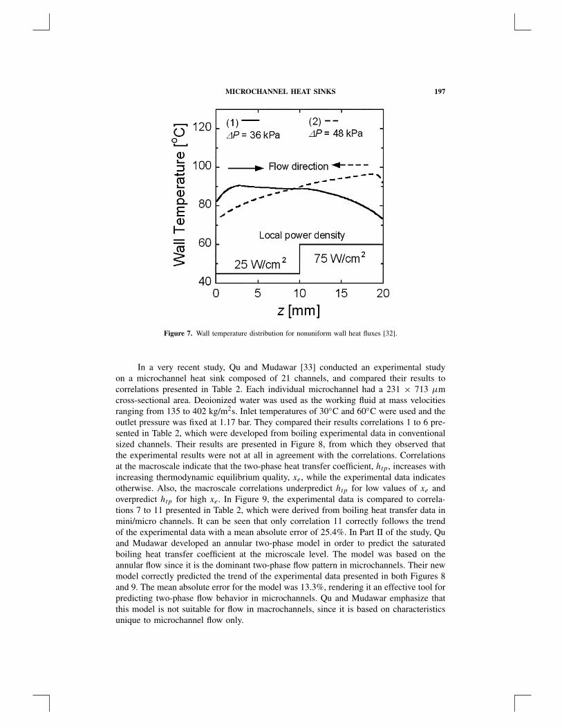
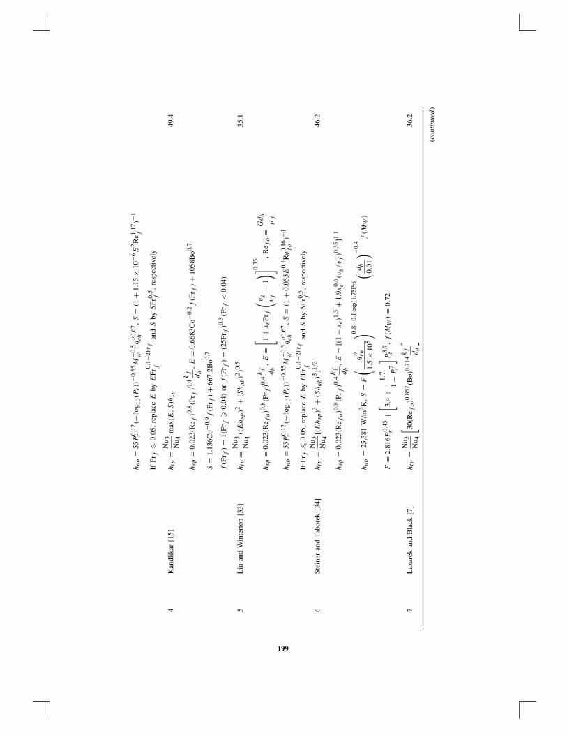
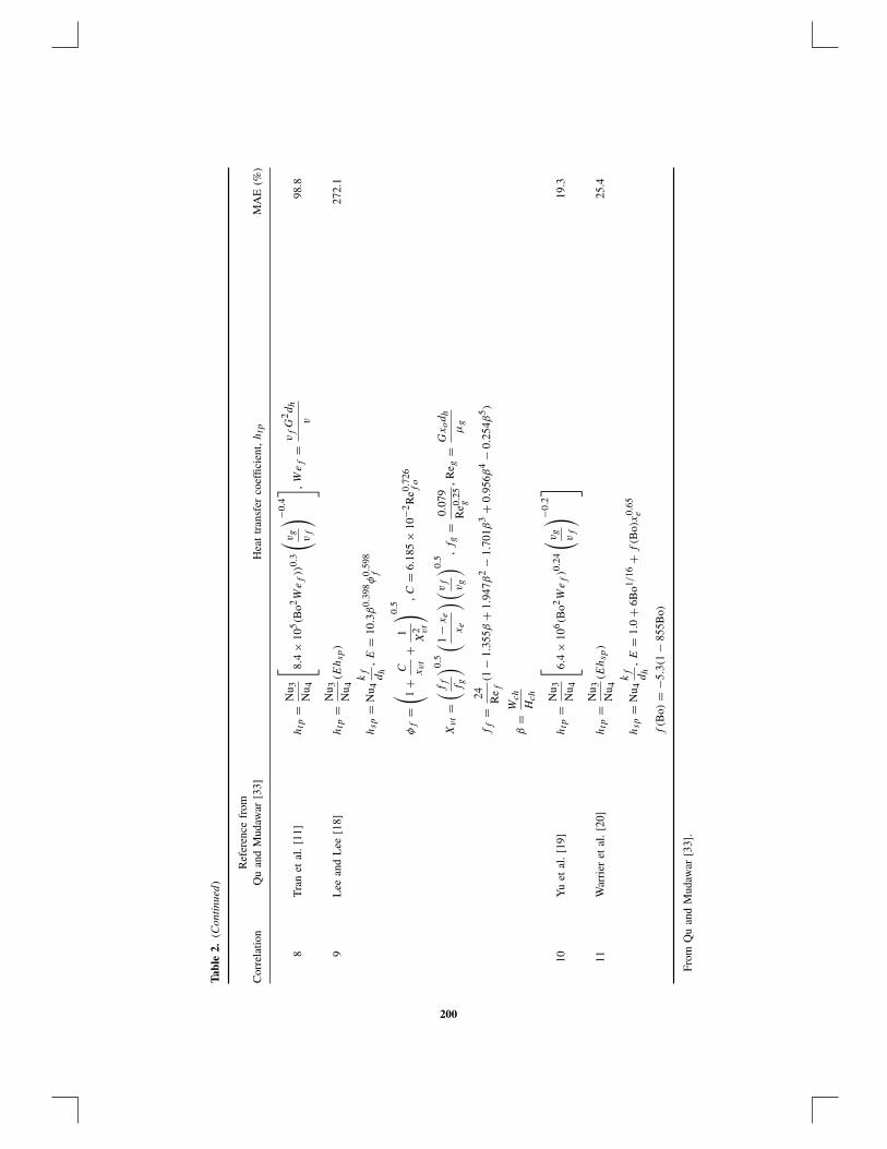
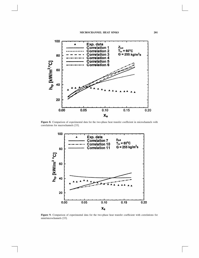
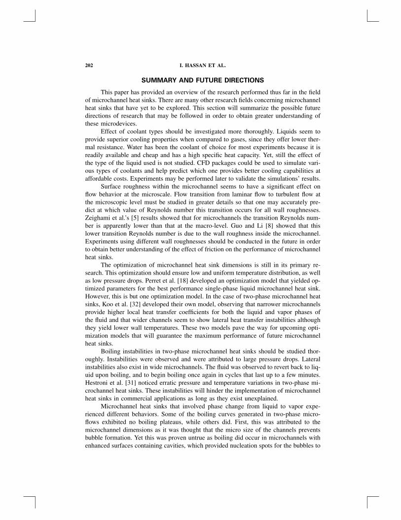
In a very recent study, Qu and Mudawar [33] conducted an experimental studyon a microchannel heat sink composed of 21 channels, and compared their results tocorrelations presented in Table 2. Each individual microchannel had a 231 × 713 µmcross-sectional area. Deoionized water was used as the working fluid at mass velocitiesranging from 135 to 402 kg/m2s. Inlet temperatures of 30◦C and 60◦C were used and theoutlet pressure was fixed at 1.17 bar. They compared their results correlations 1 to 6 pre-sented in Table 2, which were developed from boiling experimental data in conventionalsized channels. Their results are presented in Figure 8, from which they observed thatthe experimental results were not at all in agreement with the correlations. Correlationsat the macroscale indicate that the two-phase heat transfer coefficient, htp, increases withincreasing thermodynamic equilibrium quality, xe, while the experimental data indicatesotherwise. Also, the macroscale correlations underpredict htp for low values of xe andoverpredict htp for high xe. In Figure 9, the experimental data is compared to correla-tions 7 to 11 presented in Table 2, which were derived from boiling heat transfer data inmini/micro channels. It can be seen that only correlation 11 correctly follows the trendof the experimental data with a mean absolute error of 25.4%. In Part II of the study, Quand Mudawar developed an annular two-phase model in order to predict the saturatedboiling heat transfer coefficient at the microscale level. The model was based on theannular flow since it is the dominant two-phase flow pattern in microchannels. Their newmodel correctly predicted the trend of the experimental data presented in both Figures 8and 9. The mean absolute error for the model was 13.3%, rendering it an effective tool forpredicting two-phase flow behavior in microchannels. Qu and Mudawar emphasize thatthis model is not suitable for flow in macrochannels, since it is based on characteristicsunique to microchannel flow only.
Tabl
e2.
Cor
rela
tions
used
for
com
pari
son
byQ
uan
dM
udaw
ar
Ref
eren
cefr
omC
orre
latio
nQ
uan
dM
udaw
ar[3
3]H
eat
tran
sfer
coef
ficie
nt,htp
MA
E(%
)
1C
hen
[8],
Ede
lste
inhtp
=N
u 3N
u 4(E
hsp
+Shab)
43.9
etal
.[3
0]
hsp
=0.
023(
Re f
)0.8(P
r f)0.
4kf dh
,hnb
=0.
0012
2
k
0.79
fc
0.45
P,f
v0.
24g
σ0.
5µ
0.29
fh
0.24
fg
v0.
49f
�T
0.24
sat
�P
0.75
sat
E=( 1
+1
x0.
5tt
) 1.78
,S
=0.
9622
−0.
5822
[ tan−
1
( Re f
E1.
25
6.18
×10
4
)]
Re f
=G
(1−
xe)d
b
µf
,Pr
f=
c P,f
µf
kf
,X
tt=( 1
−xe
xe
) 0.9( v f v
g
) 0.5( µ
f
µg
) 0.1
2Sh
ah[9
,31
]htp
=N
u 3N
u 4m
ax(E
,S)h
sp53
.7
hsp
=0.
023(
Re f
)0.8(P
r f)0.
4kf dh
For
NN
>1.
0,S
=1.
8/N
N0.
8,E
=23
0Bo0.
5(B
o>
3×
10−5
)or
E=
1+
46B
o0.5(B
o<
3×
10−1
)
For
0.1
<N
N�
1.0,
S=
1.8/
NN
0.8,E
=F
Bo0.
5ex
p(2.
47N
N−0
.15)
For
NN
�0.
1,S
=1.
8/N
N0.
8,E
=F
Bo0.
5ex
p(2.
47N
N−0
.15)
F=
14.7
(Bo
�11
×10
−4)
orF
=15
.43(
Bo
<11
×10
−4)
NN
=C
o(Fr
f�
0.04
)or
NN
=0.
38Fr
−0.3
fC
o(Fr
f<
0.04
)
Co
=( 1
−xe
xe
) 0.8( v f v
g
) 0.5,
Frf
=v
2 fG
2
gdh
3G
ungo
ran
dW
inte
rton
[32]
htp
=N
u 3N
u 4(E
hsp
+Shnb)
50.1
hsp
=0.
023(
Re f
)0.8(P
r f)0.
4kf dh
,E
=1
+24
000B
o1.16
+1.
37
( 1 Xu
) 0.86
198
hnb
=55
P0.
12r
(−lo
g 10(P
r))
−0.5
5M
−0.5
Wq
′′0.6
7ch
,S
=(1
+1.
15×
10−6
E2R
e1.17
f)−
1
IfFr
f�
0.05
,re
plac
eE
byE
Fr0.
1−2F
r ff
and
Sby
SFr
0.5
f,
resp
ectiv
ely
4K
andl
ikar
[15]
htp
=N
u 3N
u 4m
ax(E
,S)h
sp49
.4
hsp
=0.
023(
Re f
)0.8(P
r f)0.
4kf dh
,E
=0.
6683
Co−
0.2f(F
r f)+
1058
Bo0.
7
S=
1.13
6Co−
0.9f(F
r f)+
667.
2Bo0.
7
f(F
r f)=
1(Fr
f�
0.04
)or
f(F
r f)=
(25F
r f)0.
3(F
r f<
0.04
)
5L
iuan
dW
inte
rton
[33]
htp
=N
u 3N
u 4((E
hsp
)2+
(Shnb)2
)0.5
35.1
hsp
=0.
023(
Re f
o)0.
8(P
r f)0.
4kf dh
,E
=[ 1
+xePr
f
( vg
vf
−1)] 0
.35
,R
e fo
=G
dh
µf
hnb
=55
P0.
12r
(−lo
g 10(P
r))
−0.5
5M
−0.5
Wq
′′0.6
7ch
,S
=(1
+0.
055E
0.1R
e0.16
fo
)−1
IfFr
f�
0.05
,re
plac
eE
byE
Fr0.
1−2F
r ff
and
Sby
SFr
0.5
f,
resp
ectiv
ely
6St
eine
ran
dTa
bore
k[3
4]htp
=N
u 3N
u 4[(E
hsp
)3+
(Shnb)3
]1/3
46.2
hsp
=0.
023(
Re f
o)0.
8(P
r f)0.
4kf dh
,E
=[(1
−xe)1.
5+
1.9x
0.6
e(v
g/vf)0.
35]1.
1
hnb
=25
,581
W/m
2K
,S
=F
(q
′′ ch
1.5
×10
5
) 0.8−0
.1ex
p(1.
75Pr
)( d
h
0.01
) −0.4
f(M
W)
F=
2.81
6P0.
45r
+[ 3.
4+
1.7
1−
P7 r
] P3.
7t
,f(M
W)=
0.72
7L
azar
ekan
dB
lack
[7]
htp
=N
u 3N
u 4
[ 30(R
e fo)0.
857(B
o)0.
714kf dh
]36
.2
(con
tinu
ed)
199
Tabl
e2.
(Con
tinu
ed)
Ref
eren
cefr
omC
orre
latio
nQ
uan
dM
udaw
ar[3
3]H
eat
tran
sfer
coef
ficie
nt,htp
MA
E(%
)
8T
ran
etal
.[1
1]htp
=N
u 3N
u 4
8.4
×10
5(B
o2W
e f))
0.3
( vg
vf
) −0.4 ,W
e f=
vfG
2dh
v98
.8
9L
eean
dL
ee[1
8]htp
=N
u 3N
u 4(E
hsp
)27
2.1
hsp
=N
u 4kf dh
,E
=10
.3β
0.39
8φ
0.59
8f
φf
=( 1
+C xvt
+1
X2 vt
) 0.5,C
=6.
185
×10
−2R
e0.72
6fo
Xvt=( f f f
g
) 0.5( 1
−xe
xe
)(vf vg
) 0.5,fg
=0.
079
Re0.
25g
,R
e g=
Gxodh
µg
ff
=24 Re f
(1−
1.35
5β+
1.94
7β2
−1.
701β
3+
0.95
6β4
−0.
254β
5)
β=
Wch
Hch
10Y
uet
al.
[19]
htp
=N
u 3N
u 4
6.4
×10
6(B
o2W
e f)0.
24
( vg
vf
) −0.2
19.3
11W
arri
eret
al.
[20]
htp
=N
u 3N
u 4(E
hsp
)25
.4
hsp
=N
u 4kf dh
,E
=1.
0+
6Bo1/
16+
f(B
o)x
0.65
e
f(B
o)=
−5.3
(1−
855B
o)
From
Qu
and
Mud
awar
[33]
.
200
MICROCHANNEL HEAT SINKS 201
Figure 8. Comparison of experimental data for the two-phase heat transfer coefficient in microchannels withcorrelations for macrochannels [33].
Figure 9. Comparison of experimental data for the two-phase heat transfer coefficient with correlations formini/microchannels [33].
202 I. HASSAN ET AL.
SUMMARY AND FUTURE DIRECTIONS
This paper has provided an overview of the research performed thus far in the fieldof microchannel heat sinks. There are many other research fields concerning microchannelheat sinks that have yet to be explored. This section will summarize the possible futuredirections of research that may be followed in order to obtain greater understanding ofthese microdevices.
Effect of coolant types should be investigated more thoroughly. Liquids seem toprovide superior cooling properties when compared to gases, since they offer lower ther-mal resistance. Water has been the coolant of choice for most experiments because it isreadily available and cheap and has a high specific heat capacity. Yet, still the effect ofthe type of the liquid used is not studied. CFD packages could be used to simulate vari-ous types of coolants and help predict which one provides better cooling capabilities ataffordable costs. Experiments may be performed later to validate the simulations’ results.
Surface roughness within the microchannel seems to have a significant effect onflow behavior at the microscale. Flow transition from laminar flow to turbulent flow atthe microscopic level must be studied in greater details so that one may accurately pre-dict at which value of Reynolds number this transition occurs for all wall roughnesses.Zeighami et al.’s [5] results showed that for microchannels the transition Reynolds num-ber is apparently lower than that at the macro-level. Guo and Li [8] showed that thislower transition Reynolds number is due to the wall roughness inside the microchannel.Experiments using different wall roughnesses should be conducted in the future in orderto obtain better understanding of the effect of friction on the performance of microchannelheat sinks.
The optimization of microchannel heat sink dimensions is still in its primary re-search. This optimization should ensure low and uniform temperature distribution, as wellas low pressure drops. Perret et al. [18] developed an optimization model that yielded op-timized parameters for the best performance single-phase liquid microchannel heat sink.However, this is but one optimization model. In the case of two-phase microchannel heatsinks, Koo et al. [32] developed their own model, observing that narrower microchannelsprovide higher local heat transfer coefficients for both the liquid and vapor phases ofthe fluid and that wider channels seem to show lateral heat transfer instabilities althoughthey yield lower wall temperatures. These two models pave the way for upcoming opti-mization models that will guarantee the maximum performance of future microchannelheat sinks.
Boiling instabilities in two-phase microchannel heat sinks should be studied thor-oughly. Instabilities were observed and were attributed to large pressure drops. Lateralinstabilities also exist in wide microchannels. The fluid was observed to revert back to liq-uid upon boiling, and to begin boiling once again in cycles that last up to a few minutes.Hestroni et al. [31] noticed erratic pressure and temperature variations in two-phase mi-crochannel heat sinks. These instabilities will hinder the implementation of microchannelheat sinks in commercial applications as long as they exist unexplained.
Microchannel heat sinks that involved phase change from liquid to vapor expe-rienced different behaviors. Some of the boiling curves generated in two-phase micro-flows exhibited no boiling plateaus, while others did. First, this was attributed to themicrochannel dimensions as it was thought that the micro size of the channels preventsbubble formation. Yet this was proven untrue as boiling did occur in microchannels withenhanced surfaces containing cavities, which provided nucleation spots for the bubbles to
MICROCHANNEL HEAT SINKS 203
form. The existence of the boiling plateau is of great importance as it allows the removalof high amounts of heat at relatively low and constant temperatures. Further testing ontwo-phase flow in microchannels of hydraulic diameters less than 100 µm should beperformed to determine whether the boiling plateaus in the boiling curves generally donot exist for microchannels of these sizes.
Different microchannel geometries should be tested to see if one shape in particularyields a better cooling performance. Experimental data for different geometries shouldbe tested for two-phase flow in order to generate accurate flow regime maps that maybe able to predict the flow pattern. Transitional flow regimes should also be clearlyand universally defined in experiments in order to avoid confusion when attempting tomodel the flow regime maps. This experimental data will also be useful in generatingmodels that may predict the heat transfer coefficient associated with two-phase flow inmicrochannels.
Fluid properties are affected by variations in temperature; however, most of thestudies cited did not consider this fact. Studies accounting for the temperature-dependentfluid properties will certainly give more accurate and realistic results than constant fluidproperties studies, thus predicting the real performance of microchannel heat sinks.
Spatially varying heat fluxes should be investigated further in the future. There wasbut one study that assumed spatially varying heat fluxes, which concluded that the besttwo-phase microchannel heat sinks have 80% of the total heat flux applied to the latterhalf of the channel. Future work might provide other nonuniformity patterns that mayenhance microchannel heat sink performance.
REFERENCES
1. D. B. Tuckerman and F. R. Pease, Microcapillary Thermal Interface Technology for VLSIPackaging, Digest of Technical Papers—Symposium on VLSI Technology, Maui, HI, pp. 60–61, 1983.
2. D. B. Tuckerman, Heat-Transfer Microstructures for Integrated Circuits, Ph.D. thesis, StanfordUniversity, 1984.
3. S. T. Poh and E. Y. K. Ng, Heat Transfer and Flow Issues in Manifold Microchannel HeatSinks: A CFD Approach, Proc. Electronic Packaging Technology Conference, EPTC, pp. 246–250, 1998.
4. K. Kawano, K. Minakami, H. Iwasaki, and M. Ishizuka, Microchannel Heat Exchanger forCooling Electrical Equipment, Proc. ASME Heat Transfer Division, vol. 3, pp. 173–180, 1998.
5. R. Zeighami, D. Laser, P. Zhou, M. Asheghi, S. Devasenathipathy, T. Kenny, J. Santiago, andK. Goodson, Experimental Investigation of Flow Transition in Microchannels Using Micron-Resolution Particle Image Velocimetry, Proc. 7th Intersociety Conference on Thermomechan-ical Phenomena in Electronic Systems, ITHERM, vol. 2, pp. 148–153, 2000.
6. M. M. Rahman, Measurements of Heat Transfer in Microchannel Heat Sinks, InternationalCommunications in Heat and Mass Transfer, vol. 27, no. 4, pp. 495–506, 2000.
7. Z.-X. Li, D. X. Du, and Z.-Y. Guo, Experimental Study on Flow Characteristics of Liquid inCircular Microtubes, Proc. International Conference on Heat Transfer and Transport Phenom-ena in Microscale, pp. 162–167, 2000.
8. Z.-Y. Guo and Z.-X. Li, Size Effect on Single-Phase Channel Flow and Heat Transfer atMicroscale, International Journal of Heat and Fluid Flow, vol. 24, pp. 284–297, 2003.
9. P. Gao, S. Le Person, and M. Favre-Marinet, Scale Effects on Hydrodynamics and Heat Transferin Two-Dimensional Mini and Microchannels, International Journal of Thermal Sciences, vol.41, pp. 1017–1027, 2002.
204 I. HASSAN ET AL.
10. R. R. Riehl, P. Seleghim, Jr., and J. M. Ochterbeck, Comparison of Heat Transfer Corre-lations for Single- and Two-Phase Microchannel Flows for Microelectronics Cooling, Proc.Intersociety Conference on Thermomechanical Phenomena in Electronic Systems, ITHERM,pp. 409–416, 1998.
11. X. F. Peng and B. X. Wang, Forced Convection and Flow Boiling Heat Transfer for LiquidFlowing through Microchannels, International Journal of Heat and Mass Transfer, vol. 36,no. 14, pp. 3421–3427, 1993.
12. B. X. Wang and X. F. Peng, Experimental Investigation on Liquid Forced-Convection HeatTransfer through Microchannels, International Journal of Heat and Mass Transfer, vol. 37,no. 1, pp. 73–82, 1994.
13. X. F. Peng and G. P. Peterson, The Effect of Thermofluid and Geometrical Parameters onConvection of Liquids through Rectangular Microchannels, International Journal of Heat andMass Transfer, vol. 38, no. 4, pp. 755–758, 1995.
14. X. F. Peng and G. P. Peterson, Convective Heat Transfer and Flow Friction for Water Flowin Microchannel Structures, International Journal of Heat and Mass Transfer, vol. 39, no. 12,pp. 2599–2608, 1996.
15. E. Y. K. Ng, C. P. Tso, Z. M. Wen, and K. F. Choo, Numerical Simulation of Flow andConjugate Heat Transfer in a Microchannel for Electronics Cooling, Journal of ElectronicsManufacturing, vol. 9, no. 2, pp. 141–153, 1999.
16. A. G. Fedorov and R. Viskanta, Analysis of Conjugate Heat Transfer in a Three-DimensionalMicrochannel Heat Sink for Cooling of Electronic Components, Proc. ASME Heat TransferDivision, vol. 364–363, pp. 89–98, 1999.
17. A. G. Fedorov and R. Viskanta, Three-Dimensional Conjugate Heat Transfer in the Microchan-nel Heat Sink for Electronic Packaging, International Journal of Heat and Mass Transfer,vol. 43, no. 3, pp. 399–415, 2000.
18. C. Perret, J. Boussey, C. Schaeffer, and M. Coyaud, Analytic Modeling, Optimization, andRealization of Cooling Devices in Silicon Technology, IEEE Transactions on Components andPackaging Technologies, vol. 23, no. 4, pp. 665–672, 2000.
19. Z.-Y. Guo and X. B. Wu, Compressibility Effect on the Gas flow and Heat Transfer in aMicrotube, International Journal of Heat and Mass Transfer, vol. 40, pp. 3251–3254, 1997.
20. Z.-Y. Guo and X. B. Wu, Further Study on the Compressibility Effect on the Gas Flow andHeat Transfer in a Microtube, Microscale Thermophysical Engineering, vol. 2, pp. 111–120,1998.
21. M. J. Marongiu, Compressibility Effects in the Design of Gas-Cooled Microchannel Heat Sinks,Proc. 5th Intersociety Conference on Thermal Phenomena in Electronic Systems, pp. 124–129,1996.
22. M. J. Marongiu, B. Kusha, and G. S. Fallon, Compressible Gas-Cooled Micro-Channel HeatSink Board (Substrates), Proc. 1998 International Symposium on Microelectronics, vol. 3582,pp. 856–861, 1998.
23. A. Beskok and G. Karniadakis, A Model for Flows in Channels, Pipes, and Ducts at Microand Nano Scales, Microscale Thermophysical Engineering, vol. 3, no. 1, pp. 43–77, 1999.
24. G. Karniadakis and A. Beskok, Micro Flows: Fundamentals and Simulation, Springer-Verlag,New York, 2002.
25. J. Baker and M. E. Calvert, Effect of Variable Viscosity on Coupled Heat and MomentumTransfer in Microchannel Flows, American Society of Mechanical Engineers, Fluids Engineer-ing Division (Publication) FED, vol. 237, no. 2, pp. 775–782, 1996.
26. L. Jiang, M. Wong, and Y. Zohar, Phase Change in Microchannel Heat Sinks with IntegratedTemperature Sensors, Journal of Microelectromechanical Systems, vol. 8, no. 4, pp. 358–365,1999.
27. L. Jiang, M. Wong, and Y. Zohar, Forced Convection Boiling in a Microchannel Heat Sink,Journal of Microelectromechanical Systems, vol. 10, no. 1, pp. 80–87, 2001.

MICROCHANNEL HEAT SINKS 205
28. J. Koo , L. Jiang, L. Zhang, P. Zhou, S. Banerjee, T. Kenny, J. Santiago, and K. Goodson, Mod-eling of Two-Phase Microchannel Heat Sinks for VLSI Chips, Proc. 14th IEEE InternationalConference on Micro Electro Mechanical Systems (MEMS) 2001, pp. 422–426, 2001.
29. L. Zhang, J. Koo, L. Jiang, M. Asheghi, K. Goodson, J. G. Santiago, and T. Kenny, Measure-ments and Modeling of Two-Phase Flow in Microchannels with Nearly Constant Heat FluxBoundary Conditions, Journal of Microelectromechanical Systems, vol. 11, no. 1, pp. 12–19,2002.
30. L. Zhang, E. Wang, J. Koo, L. Jiang, K. Goodson, J. Santiago, and T. Kenny, EnhancedNucleate Boiling in Microchannels, Proc. 15th IEEE International Conference on Micro ElectroMechanical Systems (MEMS) 2002, pp. 89–92, 2002.
31. G. Hestroni, A. Mosyak, Z. Segal, and G. Ziskind, A Uniform Temperature Heat Sink forCooling of Electronic Devices, International Journal of Heat and Mass Transfer, vol. 45,no. 16, pp. 3275–3286, 2002.
32. J. Koo, L. Jiang, A. Bari, L. Zhang, and E. Wang, Convective Boiling in Microchannel HeatSinks with Spatially Varying Heat Generation, Thermomechanical Phenomena in ElectronicSystems–Proceedings of the Intersociety Conference, pp. 341–346, 2002.
33. W. Qu and I. Mudawar, Flow Boiling Heat Transfer in Two-Phase Micro-Channel Heat Sinks:Part I: Experimental Investigation and Assessment of Correlation Methods. Part II: AnnularTwo-Phase Flow Model, International Journal of Heat and Mass Transfer, vol. 46, pp. 2755–2784, 2003.