micro-manufacturing engineering and technology || manufacturing execution systems for...
TRANSCRIPT
24Manufacturing
Execution Systems for
Micro-ManufacturingMatthias Meier
INTRODUCTION
Looking at manufacturing from a bird’s-eye per-spective reveals two important generic processesthat characterize these enterprises – the productlifecycle process on the one hand and the customerorder process on the other. Fig. 24-1 shows asketch of these processes and their interrelation.The product lifecycle process that is shown on theX-axis describes the activities that are executed todevelop newproducts, i.e. to generate innovationsand to bring them to the market. The customer-order process on the Y-axis shows the activitiesperformed to produce these products based onmarket needs and to deliver them to customers.Over the last few years the integration of activitieswithin both of these processes has been recog-nized as a major capability for optimization. Fur-thermore, the time required for the execution ofthese processes on the one hand and the efficiencyand effectiveness of the execution of activitieswithin these processes on the other are consideredas generic optimization goals. Adjusting thesepotentials requires a significant amount of infor-mation technology (IT) support, as complex con-trol loops have to be built up – some of them evenbridging multiple process activities; with largeamounts of data needing to be collected andto be processed in order to change the process
variables in the right way. The production activityis the linchpinwhere both processes overlap and istherefore definitely an activity to be consideredwhen designing the overall IT architecture of anenterprise.
While the foregoing remark is already true fortoday’s state-of-the-art factories, there are a num-ber of reasons that even argue for an increasingneed of IT support for the manufacturing ofmicro-products in future, such as:1. Operating new manufacturing processes at the
edge of technical feasibility in series produc-tion often requires sophisticated IT support formonitoring and controlling these processes.
2. There is increasing pressure in terms of qualitycontrol, which arises from the automotiveindustry, for example. While extremely highquality requirements have been known for along time in aerospace, in defense and in themedical industry, the quality requirementsoriginal equipment manufacturers (OEM)request from their suppliers in the automotiveindustry have significantly risen over the lastfew years. The goal of the OEMs is to reducethe number of quality issues as experiencedwith several car series in recent years – whichwere often caused by defective electronic com-ponents. The IT environment is one building
C H A P T E R
377

block for implementing zero-defect strategiesas requested by the OEMs.
3. Increasing low cost production capacities inseveral parts of the world put additional costpressure on numerous industries. Adjustingoptimization potentials throughout the pro-cess chains is another goal to be supportedby IT systems.Further discussions within this chapter are
focused on the ‘Production’ activity and the ITenvironment supporting it. This chapter aims todeliver insights into concepts, standards and tech-nologies used to implement the production-related IT environment for micro-/nano-manufacturing. The first section provides a gen-eral overview of the production IT landscape. Itexplains important terms, architecture layers,and corresponding systems and their scope. Inthe second section the scope is narrowed to themanufacturing-execution systems, which areinvestigated in more detail. The third section
briefly reviews approaches to implement the con-cepts discussed earlier. The last section closes thechapter with some considerations on relevantstandardization work.
PRODUCTION IT OVERVIEW
For the following considerations, the scope is nar-rowed to discrete manufacturing. Investigating amicro-manufacturing enterprise from a produc-tion IT point of view requires some initial discus-sion of the organizational structure of the physicalassets of such an enterprise. The hierarchicalstructure shown in Fig. 24-2, which is based onreference [1], is commonly used for this purpose.As the root of the hierarchy, the enterprise definesthe products to be manufactured and how andwhere these products are to be manufactured.Each enterprise comprises one or multiplesites. A site is mainly characterized by its physicalor geographical location and its major
FIGURE 24-1 Product lifecycle and customer-order process.
378 CHAPTER 24 Manufacturing Execution Systems for Micro-Manufacturing
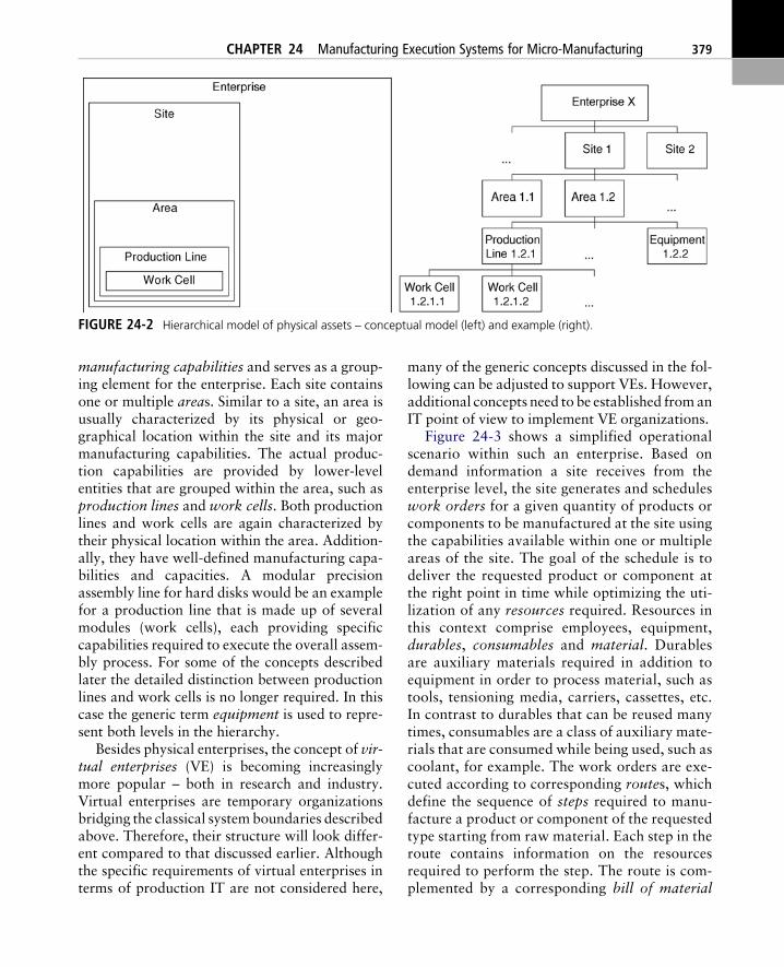
manufacturing capabilities and serves as a group-ing element for the enterprise. Each site containsone or multiple areas. Similar to a site, an area isusually characterized by its physical or geo-graphical location within the site and its majormanufacturing capabilities. The actual produc-tion capabilities are provided by lower-levelentities that are grouped within the area, such asproduction lines and work cells. Both productionlines and work cells are again characterized bytheir physical location within the area. Addition-ally, they have well-defined manufacturing capa-bilities and capacities. A modular precisionassembly line for hard disks would be an examplefor a production line that is made up of severalmodules (work cells), each providing specificcapabilities required to execute the overall assem-bly process. For some of the concepts describedlater the detailed distinction between productionlines and work cells is no longer required. In thiscase the generic term equipment is used to repre-sent both levels in the hierarchy.
Besides physical enterprises, the concept of vir-tual enterprises (VE) is becoming increasinglymore popular – both in research and industry.Virtual enterprises are temporary organizationsbridging the classical system boundaries describedabove. Therefore, their structure will look differ-ent compared to that discussed earlier. Althoughthe specific requirements of virtual enterprises interms of production IT are not considered here,
many of the generic concepts discussed in the fol-lowing can be adjusted to support VEs. However,additional concepts need to be established fromanIT point of view to implement VE organizations.
Figure 24-3 shows a simplified operationalscenario within such an enterprise. Based ondemand information a site receives from theenterprise level, the site generates and scheduleswork orders for a given quantity of products orcomponents to be manufactured at the site usingthe capabilities available within one or multipleareas of the site. The goal of the schedule is todeliver the requested product or component atthe right point in time while optimizing the uti-lization of any resources required. Resources inthis context comprise employees, equipment,durables, consumables and material. Durablesare auxiliary materials required in addition toequipment in order to process material, such astools, tensioning media, carriers, cassettes, etc.In contrast to durables that can be reused manytimes, consumables are a class of auxiliary mate-rials that are consumed while being used, such ascoolant, for example. The work orders are exe-cuted according to corresponding routes, whichdefine the sequence of steps required to manu-facture a product or component of the requestedtype starting from raw material. Each step in theroute contains information on the resourcesrequired to perform the step. The route is com-plemented by a corresponding bill of material
FIGURE 24-2 Hierarchical model of physical assets – conceptual model (left) and example (right).
CHAPTER 24 Manufacturing Execution Systems for Micro-Manufacturing 379

that describes in a structured way the parts andcomponents required to manufacture the prod-uct or component. In order to monitor the prog-ress of work orders over time, sufficient feed-back needs to be provided from the equipmentlevel to higher levels while the route is beingexecuted. Besides the information on progressand process results in terms of quantities, feed-back on quality needs to be collected to detectpossible issues early and to ensure the requiredlevel of quality upon completion of the job.
The term ‘Production IT’ refers to the IT land-scape that is dedicated to support the specific sub-process and activities within the ‘Production’activity shown in Fig. 24-1, i.e. it provides toolsto efficiently and effectively operate production.
Furthermore, the production IT landscape servesas a building block for process integration withinboth of the generic processes described earlier –the product lifecycle process and the customer-order process:1. It supplies both processes with accurate infor-
mation from production in a timely manner,such as information on the processing statusof customer orders, available capacities – bothare essential for the customer-order process –and process and quality data from production,which complement product lifecycle-relateddata that have been generated in other phases.Access to data from production is required as afirst prerequisite to control and optimize theoverall processes.
FIGURE 24-3 Operational scenario (example)
380 CHAPTER 24 Manufacturing Execution Systems for Micro-Manufacturing
2. It provides other activities of the generic pro-cesses with suitable interfaces to influence pro-duction, which is the second prerequisite toestablish overall control loops, including pro-duction.Although the specific requirements to be ful-
filled by the production IT environment differfrom industry to industry on the one hand andfrom company to company on the other, thereexists a set of generic concepts that many indus-tries have in common: these concepts will bediscussed in the following. The commonapproach to define both the scope and responsi-bility of the production IT landscape is derivedfrom the scheduling and control hierarchy,which is based on the organizational structureof the enterprise, as described earlier. Each levelwithin the hierarchy has corresponding spheres
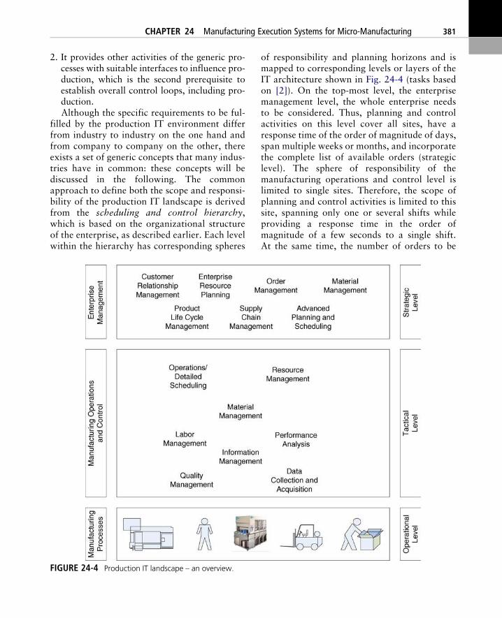
of responsibility and planning horizons and ismapped to corresponding levels or layers of theIT architecture shown in Fig. 24-4 (tasks basedon [2]). On the top-most level, the enterprisemanagement level, the whole enterprise needsto be considered. Thus, planning and controlactivities on this level cover all sites, have aresponse time of the order of magnitude of days,span multiple weeks or months, and incorporatethe complete list of available orders (strategiclevel). The sphere of responsibility of themanufacturing operations and control level islimited to single sites. Therefore, the scope ofplanning and control activities is limited to thissite, spanning only one or several shifts whileproviding a response time in the order ofmagnitude of a few seconds to a single shift.At the same time, the number of orders to be
FIGURE 24-4 Production IT landscape – an overview.
CHAPTER 24 Manufacturing Execution Systems for Micro-Manufacturing 381
considered is rather limited (tactical level). Thebottom-most level, which reflects the actualmanufacturing processes, is finally concernedwith the execution of single process steps. Thus,the planning horizon is further limited to theorder of magnitude of seconds or minutes. Atthe same time a response time of the order ofmagnitude of milliseconds to seconds has to beprovided. In addition to its specific tasks, eachlevel has to present a sufficient amount of trans-parency, i.e. to supply the upper layer with accu-rate and meaningful information with a definedmaximum delay and with suitable interfaces topropagate information.
Although the specific shape and the boundariesof these levels differ slightly from industry toindustry and from solution to solution, the basicconcept – including the levels discussed above – iswidely spread throughout many industries.
EXPLORING THE MANUFACTURINGOPERATIONS AND CONTROL LEVEL
Based on the overall picture of the production ITlandscape described above, the following sec-tions will discuss the role of the manufacturingoperations and control layer in more detail –especially the class of manufacturing executionsystems (MES), which plays a major role in thiscontext. MES systems bridge the gap betweenmanufacturing processes – including their con-trol systems – and the enterprise managementsystems as shown above. They control and mon-itor operations in production, are targeted toadjust optimization potentials within produc-tion, and facilitate the level of transparencybetween enterprise management and productionthat is required to implement complex process-integration scenarios, as described above. Thetask-oriented view defined by [2] has beenselected as the basic structure for this discussion,as it gives good insight into the MES world froma user’s perspective. The description of the MEStasks is complemented by a discussion of majorconcepts and terms to be considered in the MESenvironment.
Operations/Detailed Scheduling
Operations/detailed scheduling optimizes the exe-cution of available work orders – which have usu-ally been generated by higher level systems –based on a set of predefined optimization goals,while considering the constraints of the produc-tion under consideration. Generic optimizationgoals are:1. The generation of a schedule that is actually
executable while considering the availabilityof resources and material.
2. The reduction of set-up times, cycle time andwork in progress.
3. An increase of throughput, resource utilizationand on-time delivery.A major characteristic of this task at the MES
level is its real-time behavior, i.e. the schedule iscontinuously adjusted based on events and distur-bances that occur on the shop floor. Thesechanges are immediately enforced in production.Thus, the MES is able to handle unforeseenevents, such as resource breakdowns, missingmaterial, issues with production processes andquality issues. Generally, there are twoapproaches to be distinguished, based on the plan-ning horizon: the scheduling approach and thedispatching approach. The scheduling approachattempts to generate a plan for assigning a set ofjobs (task in the context of the architecture levelconsidered) to a set of resources based on givenconstraints and optimization criteria within therange of a scheduling horizon. The dispatchingapproach is aimed at the optimization ofresources in real-time by evaluating context infor-mation based on a given set of rules. Two typicalquestions answered by the dispatching sub-systemin the case of job-shop production are:1. What is next for a given resource? – i.e. which
of the jobs within the job queue of this resourceshould be executed first based on the currentcontext information and the set of dispatchingrules? Examples for context information are:resource states, job priorities, time constraints,delivery dates, etc.
2. Where is next for a givenmaterial? – i.e. what isthe best-suited next location for some material
382 CHAPTER 24 Manufacturing Execution Systems for Micro-Manufacturing
after completing a process job on a givenresource? In this case the context to be consid-ered could be the next step based on the routeassigned to this work order, the state ofresources of the type that is required next, etc.Due to the ad-hoc nature of decisions in the
case of dispatching, this approach is mainly fol-lowed in highly dynamic environments as knownfrom semiconductor manufacturing, for example,as the large number of disturbances within theproduction environment would require very fre-quent rescheduling. As the schedule generation israther resource consuming (in terms of computa-tional resources) and time consuming, it is diffi-cult to implement the scheduling approach in thisenvironment.
To deal with scheduling conflicts that arise dueto disturbances as described above or due to com-peting optimization goals caused by committeddelivery dates and varying job priorities, forexample, is an important aspect of the opera-tions/detailed scheduling task. The system needsto provide the capability to handle these conflictsautomatically, if possible, or to supply responsiblepeople with sufficient information to be able totake the right decision manually.
Resource Management
Resource management is mainly concerned withthe task of ensuring the availability of theresources required for executing work orders. Inthis context, the term ‘resource’ comprisesmachines, equipment, durables and non-materialdurables. The former terms were explained earlier– the latter notion of non-material durables refersto auxiliary resources such as numerical control(NC) programs or process programs (PP) in gen-eral. In several industries process programs arealso referred to as recipes. Recipes are programsthat are executed by the equipment control systemin order to control a specific process. The behav-ior of the control system can be adjusted by select-ing different recipes or by adjusting parameterswithin given recipes.
The first aspect of the resource-managementtask comprises the management of resource-
related master data. For each resource a recordof generic information needs to be maintained,including properties such as the identifier (ID),the location, and capacities and maintenance-related data. Furthermore, resources have to bemodeled in sufficient detail in order to support theselected operations/detailed scheduling approachand other MES functionalities. Usually, resourcesaremodeled in the form of a hierarchical structurethat describes relevant components and their rela-tionship. A simple example would be some clusterequipment, i.e. a class of items of equipmentwhich have several process chambers that can beoperated in parallel. Each process chamber offersspecific process capabilities. An internal logisticssystem is responsible for the material transportwithin the equipment. The mainframe could bemodeled as the root of a tree that contains a setof load ports and a set of process chambers. Ifsingle chambers are being considered within theprocess of detailed scheduling, equipment has tobe modeled down to the chamber level. Eachobject within the tree has a specific state modelassigned, including states such as ‘idle’,‘processing’, or ‘locked’ that reflect the currentstate of the component at run-time. This statemodel is used to specify rules for operating theresource at run-time. A rule of that type coulddefine that a resource in state ‘locked’ may notbe used for processing, for example. Furthermore,resources have a set of capabilities assigned thatdefine the type of jobs that can be executed. At thesame time, resources are often integrated into anoverall resource hierarchy, such as equipmentgroups, areas and facilities, and are linked withrelated resources. Machine/tool relations wouldbe an example of this type of link. In addition tothe equipment model-related master data,resource management has to cover the sub-tasksof recipe and parameter management.
The second aspect of resource management isrelated to the run-time behavior of resources. Theresource tracking task performs book-keeping onany relevant dynamic data related to resources,including information on jobs and recipes exe-cuted on the resource, state changes based onthe resource model and maintenance-related
CHAPTER 24 Manufacturing Execution Systems for Micro-Manufacturing 383
information. The tracking task makes use ofevents that are gathered online from resourcesor manually logged at user terminals. If the phys-ical resource starts processing, for example, a cor-responding event is either automatically or man-ually logged for the resource, together with a timestamp. Upon receipt of this event, resource man-agement will update the corresponding resource-state model, i.e. transition it from ‘idle’ to‘processing’, and store the event in the history toallow for further analysis. The updated stateinformation is visible for other MES tasks. Up-to-date resource information is an importantrequirement for realizing complex automationscenarios with theMES, as otherMES tasks, espe-cially the detailed scheduling functionality, relyon this data. Furthermore, resource managementplays an important role in the process of resourceallocation, especially for the appropriate set-up ofresources before some production job is executedon the resource. The set-up comprises anythingthat is required in addition to the pure resourcein order to process the job, such as the appropriatetools, tensioning media, recipes and parameters.In the case of fully automated scenarios the set-upis performed automatically, e.g. the durables arerequested from connected logistics systems andrecipes and parameters are downloaded to theresource. As soon as the set-up is complete andmaterial is loaded, remote-controlled resourcescan even be automatically started via resourcemanagement.
The third aspect of resource management isalso related to the run-time behavior of resourcesand is mainly concerned with the availability ofresources. Resource properties reflecting the qual-ification state are continuously monitored, suchas the operating hours, the number of productionjobs executed, or even specific resource- or pro-cess-related properties. If limits definedwithin themaster data model are exceeded, requalificationof the resource is triggered to ensure the resourcedoes actually provide the expected process capa-bility. Similarly, the maintenance state ofresources is monitored. Based on data collectedfrom the resource and corresponding rules main-tained in the form of resource master data, pre-
ventive or predictive maintenance strategies canbe implemented in order to control the availabil-ity of resources to the maximum extent.
With a preventive maintenance strategy, main-tenance activities would be triggered as soon aspredefined threshold values of given resourceproperties are exceeded. Exchanging the coolantafter a given number of operational hours wouldbe an example for a preventive maintenance strat-egy. If required, the resource is locked for produc-tive use until the maintenance job has been exe-cuted. In the case of a predictive maintenancestrategy, resource parameters are monitored, cor-related and evaluated against a set of rules. Main-tenance tasks are triggered based on the evalua-tion results at the best-suited point in time beforethe resource breaks. The idea of this approach isto reduce the amount of waste that is potentiallygenerated by implementing a purely periodicmaintenance strategy, while securing a well-known level of availability for the set of resources.For the coolant example, this would mean chang-ing the coolant only after required material prop-erties have changed, which are continuously mon-itored. In the event of a resource breakdown,which causes an unscheduled downtime in con-trast to the scheduled downtime triggered by pre-ventive or predictive maintenance activities, amaintenance request needs to be generated basedon the corresponding resource-state change.Additional data acquired from the resource canbe linked to the maintenance request in order tospeed up the error-detection-and-repair process.
Material Management
Material management involves all tasks related tomaterial logistics in production. Special focus isput on the work in progress (WiP) management.WiP comprises material that is not residing inmanaged inventories, i.e. raw material, partiallycompleted material and final products. Similar toresources, material has a set of properties that aremonitored while it is transferred from the rawstate towards the final product. The major prop-erties of a material are its identifier, its location,its quality and its quantity. Thematerial ID allows
384 CHAPTER 24 Manufacturing Execution Systems for Micro-Manufacturing
the unique identification of an entity of material,based on a serial number, for example. Due to theamount of data that needs to be handled if singleentities of material are individually tracked anddue to the fact that many processes treat multipleentities of material at the same time, the conceptof lots (batches) is frequently used to group mate-rials for tracking. Multiple entities of material aregrouped to a lot, which has an ID assigned. Inaddition, lots can have similar properties as singleentities of material, such as quality, quantity andstate. Managing lots is part of the material man-agement domain, which includes the tasks to cre-ate, to split, tomerge or to terminate them.Createsupports the process of building lots from singleentities. Split divides a given parent lot into mul-tiple children.Merge combinesmultiple lots into asingle lot. Terminate removes the lot from thesystem.
Maintaining the history of lots or single mate-rial entities is a major task within the materialmanagement domain, which is also referred toasmaterial tracking orWiP tracking. These termsdescribe the process of documenting the completehistory (genealogy) of lots or single entities ofmaterial within production. The history containsinformation such as links to raw material data,information on the equipment the material hasbeen processed on, process data that has beencollected while processing the material on theequipment, information on quality and quantityafter each process step and material-related mea-surement and inspection data. These data arerecorded with time stamps and thus lay the foun-dation for a comprehensive material-related audittrail, which is an important building block forimplementing a traceability strategy.
Like the resource states, the material state,which is continuously updated while generatinghistory information, is an important input param-eter for the detailed scheduling functionality, as itcontains relevant data from an operations per-spective. Some examples formaterial state-relatedinformation that needs to be considered for opera-tions are:1. Materialmight be locked for further processing
(on hold). The hold status is set if quality pro-
blems are detected that need further investiga-tion, for example.
2. Time constraints caused by specific processproperties might require the next process stepto occur within a given time window or after aminimum waiting time. If such constraints areviolated this might result in scrap.Furthermore, information on available material
quantities and material locations needs to be eval-uated for planning and operations. However,material management does not onlymonitormate-rial movements, it also triggers material move-ments by internal or external logistic systems.
Labor Management
The task of labour management is closely relatedto resource management. It takes the specificproperties of ‘human resources’ into accountand supports the task of allocating sufficient per-sonnel with the right level of qualification onschedule for the production. Similar to theresource-management domain, the run-time func-tionality is based on a set of master data for singleemployees, groups of employees and the organi-zational structure. Typical attributes of a singleemployee are the personnel ID, name, qualifica-tion or certification, etc. Furthermore, the avail-ability of personnel is maintained in the context ofthe deployment scheduling.
Based on the master data described above, per-sonnel-related status information needs to bemaintained. Time recording allows for gatheringinformation on the actual availability of staff andthe jobs or tasks executed within this timeframe.This information is required as a basis to imple-ment complex work-schedule and wage models,including flexible working hours, pieceworkmodels, etc. Tracking the association of staffinformation with production jobs constitutesanother building block for implementing trace-ability strategies, as it documents who did whatand whether the person who performed a givenjob or task had the right level of qualificationor not. Functionality supporting the resourcedeployment gives an overview on the availablestaff capacities, provides support to manage these
CHAPTER 24 Manufacturing Execution Systems for Micro-Manufacturing 385
capacities and helps to assign jobs and tasks topersonnel in an efficient and effective way.
Data Collection and Acquisition
The availability of data of sufficient quality withlittle delay from production is an important pre-requisite for all of the MES tasks discussed earlier(and those to be described later). Data collectionand acquisition realizes the connectivity to themanufacturing processes with a suitable maxi-mum delay. Thereby, it lays the foundation foran up-to-date, correct and consistent processimage of the situation in production within theMES. This image is used to monitor and controlprocesses in production in real-time – as describedin other MES tasks. The meaning of ‘suitabledelay’ and ‘real-time’ depends on the actual mon-itoring and control problem to be solved. Usually,the minimum response time on theMES level is ofthe order of magnitude of a few seconds.
Generally, three approaches to data collectionand acquisition can be distinguished: manual,semi-automated and automated data collection.In the case of manual data collection, an operatormanually enters data records using some kind ofinput device. Manual data collection is frequentlyperformed using electronic forms that the opera-tor has to complete at a user terminal. Semi-auto-mated data collection needs manual interactionby a user – however, part of the data is acquiredautomatically. Data collection using bar-codeguns or RFID readers are examples of semi-auto-mated applications. Automated data collectionrequires the implementation of suitable IT inter-faces for data acquisition. The collection is eithertriggered by events that occur within the datasource or by cyclically polling the data source.Sophisticated mechanisms have been designed tospecify both the amount of data to be collectedand the frequency, based on the current need. Theconcept of data collection plans (DCP) allowsusers to dynamically determine the data to becollected for a given process. The user specifiesthe collection plan by selecting process variablesto be monitored from a set of available variablesand the desired collection frequency. As soon as
the plan is activated on the correspondingresource, the selected data is available throughthe IT interface.
Whenever raw data is collected, it needs to bechecked for plausibility and consistency beforebeing further processed. These checks arerequired independently of the approach used fordata collection. As correct and consistent data isan important prerequisite for successfully operat-ing an MES, these checks are considered to bepart of the data collection and acquisition taskin order to prevent the further processing of in-correct data. After performing the plausibilityand consistency checks, most of the data recordscollected have to be preprocessed and consoli-dated to simplify the downstream tasks. Con-verting dimensions or evaluating counters tophysical values are two examples of consolidationand preprocessing steps.
Performance Analysis
Performance analysis targets the evaluation of theperformance on the shop floor, both short termand long term. Thus, it provides support for estab-lishing control loops to influence operations onthe one hand and to optimize processes in the longrun on the other. Data that have been collected bythe MES are consolidated to suitable key perfor-mance indicators (KPIs) that lay the foundationfor further analysis. These KPIs can be comparedagainst organizational and technical targets: suit-able corrective actions are derived from theresults, if necessary. The following list providesa set of examples of key performance indicatorsthat are used throughout many industries:1. Equipment utilization. This is the fraction of
time the equipment is performing its intendedfunction during a specified time period [3].Measurement of the remaining capacity ofequipment or workplaces provides the abilityto detect bottlenecks.
2. Overall equipment efficiency (OEE).This is thefraction of the total time that equipment is pro-ducing effective units at theoretically efficientrates [4]. This is usedwidely tomeasure processefficiency.
386 CHAPTER 24 Manufacturing Execution Systems for Micro-Manufacturing
3. Cycle time. This is the analysis for all compo-nents of the cycle time for jobs, including non-productive time, and the sum of these compo-nents.There are numerous ways to make use of per-
formance analysis results and to trigger corre-sponding actions. In the simplest case the resultsare incorporated into management reports andlay the foundation for further decisions. This isespecially true for the long-term case. For theshort-term case the results of the performanceanalysis could automatically trigger actionswithin the system or could be fed into the dash-boards of control centers or information systemson the shop floor to trigger immediate action byoperational personnel.
Quality Management
The quality management task supports organiza-tions in reaching the required level of product andprocess quality as far as the shop floor is con-cerned. It comprises the aspects of quality plan-ning, management of test equipment and qualityinspection. Quality planning requires a variety ofinput data from previous process stages in theproduct lifecycle on the one hand and overallquality targets on the other that define the require-ments for quality inspection. Test plans need to betransformed into suitable system configurationsto ensure that routes and data-collection plansare appropriately set up and that the dataacquired from the shop floor are evaluated asneeded. The sampling functionality is responsiblefor selecting lots or single products for qualityinspection based on sampling plans that need tobe configured according to the test plan. A simplesampling plan could define every 50th lot to beinspected, for example. Dynamic sampling is anextension that allows for dynamic adjustments ofsampling plans at run-time. The sampling ratecould be automatically increased, if issues aredetected in production that might affect quality,for example. Quality assurance processes andmeasures need to be modeled within the MESsystem in order to enforce and to document theirexecution. Access-control based on the current
certification level of operators, the ability to issuedirectives to operators that need to be confirmedafter reading, and quality gates are examples ofmeasures to be supported by the MES environ-ment. Managing test equipment is closely relatedto resource management. However, some specificcharacteristics of test equipment have to be takeninto consideration. Especially, the support for cal-ibration traceability needs to be taken intoaccount.
Another aspect of the quality-managementtask is related to documentation, reporting andcontrol. Depending on the quality-managementsystem, corresponding documentation has to begenerated which confirms that the defined qual-ity-assurance measures have been properly exe-cuted. The quality information collected lays thefoundation for reporting the level of qualityreached and thus allows for implementingcounter-measures early, if issues are detected.Sample data collected can be evaluated using themethodology of statistical process control (SPC).SPC provides the means to monitor processes andthus to detect possible quality issues and to correctthem in the early stages of the overall productionprocess for a product. The methodology of faultdetection and classification (FDC) is used to ana-lyze quality-related data, to detect and recognizepossible issues and to derive suitable actions fromthese issues. Example actions that could be trig-gered automatically are:1. Put lots on hold;2. Stop process equipment.
Information Management
Information management is a cross-sectional taskthat is built on top of the tasks that have beendescribed earlier. It makes use of data and contextinformation available in the system, provides suit-able views of the data – both for users as well asfor otherMES tasks – and complements this infor-mation by suitable reports and evaluation results.Furthermore, the task of information manage-ment has an active component – it responds toevents reported from production in real-time.Both aspects lay the foundation for establishing
CHAPTER 24 Manufacturing Execution Systems for Micro-Manufacturing 387
complex control loops for production that take avariety of parameters into account.
Suitable views providing information in theappropriate context are not only relevant formanagement reporting, production managementand control or quality assurance, they also pro-vide the tools required to implement paperlessproduction concepts or at least strategies thatrequire a minimum amount of paper in produc-tion. Replacing paper-based lot travelers by elec-tronic lot travelers is one element of paperlessstrategies. A lot traveler contains basic propertiesof the lot, such as: its identifier and priority infor-mation; information on the route to be used, i.e.the process steps to be performed; and additionalinformation to be considered by the operator.Furthermore, it is often used to collect feedbackfrom production, such as the signatures of opera-tors confirming that certain instructions havebeen executed, quality inspection results, processdata, etc. An electronic lot traveler provides userswith the type of information required in a givencontext using IT systems. In this case, ‘context’could mean a given job at a given equipmentinstance. Other views could provide operatorswith specific information on quality trendsachieved at a particularwork stationwhichwouldhelp to achieve a constant level of quality. Thecapability to access relevant documents in a givencontext, such as drawings, manuals and workinstructions, helps operators to work efficientlyand effectively.
The ability to design, execute and monitorworkflows for the shop-floor environment thatallow the guidance of operational sequences onthe shop floor is a major task to be supported bythe MES. These workflows describe sequences ofactions, roles and responsibilities and drive alloperational sequences in a defined way. Imple-menting this task might require the MES to sup-port additional classes of master data, if this datacannot be supplied by other tasks or external sys-tems. Exception management is an additionalsub-task of information management. It targetsthe automatic resolution of exceptions that occurin production, if possible, or at least the support ofusers for resolving exceptions. Semi-automated
exception resolution would provide responsibleusers with information on possible correctiveactions and generate exception notifications forthese users by e-mail or short-message service, forexample. More sophisticated approaches to influ-ence production based on collected informationare covered by the methodologies of advancedprocess control (APC). This term covers a varietyof process-control methods and tools, such as SPCand FDC as described above, run to run (R2R)control and others.
MES IMPLEMENTATIONAND INTEGRATION INTOTHE PRODUCTION IT
There exists a variety of approaches to imple-ment MES solutions supporting the tasksdescribed above. In most cases these tasks willnot be supported by a single system, but ratherby a collection of cooperating systems. Further-more, the set of implemented tasks heavilydepends on the requirements of the industry orgroup of industries that a given solution targetsand – most importantly – the specific require-ments of the organization to be supported. Thesame holds true for the complexity of the ITlandscape and the enterprise architecture of theproduction IT environment. Figure 24-5 shows asimplified example of a production IT environ-ment that contains some typical concepts used.It is based upon the hierarchical structure shownin Fig. 24-4.1. The bottom-most layer is the equipment layer.
Equipment provides one or multiplemanufacturing-process capabilities that aremonitored and controlled by internal process-control systems, such as programmable logiccontrollers (PLC), computer numeric control-lers (CNC), embedded PCs or industry PCs(IPC). Typically, these control systems are con-nected to sensors and actuators using standard-ized field bus systems, such as PROFIBUS andCANOpen. Depending on the complexity ofthe equipment, it might again use a hierarchicalIT infrastructure internally. Examples of com-plex equipment would be cluster equipment,
388 CHAPTER 24 Manufacturing Execution Systems for Micro-Manufacturing
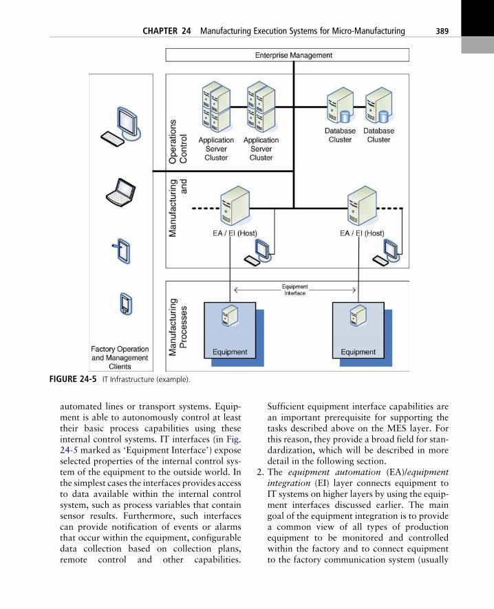
automated lines or transport systems. Equip-ment is able to autonomously control at leasttheir basic process capabilities using theseinternal control systems. IT interfaces (in Fig.24-5 marked as ‘Equipment Interface’) exposeselected properties of the internal control sys-tem of the equipment to the outside world. Inthe simplest cases the interfaces provides accessto data available within the internal controlsystem, such as process variables that containsensor results. Furthermore, such interfacescan provide notification of events or alarmsthat occur within the equipment, configurabledata collection based on collection plans,remote control and other capabilities.
Sufficient equipment interface capabilities arean important prerequisite for supporting thetasks described above on the MES layer. Forthis reason, they provide a broad field for stan-dardization, which will be described in moredetail in the following section.
2. The equipment automation (EA)/equipmentintegration (EI) layer connects equipment toIT systems on higher layers by using the equip-ment interfaces discussed earlier. The maingoal of the equipment integration is to providea common view of all types of productionequipment to be monitored and controlledwithin the factory and to connect equipmentto the factory communication system (usually
FIGURE 24-5 IT Infrastructure (example).
CHAPTER 24 Manufacturing Execution Systems for Micro-Manufacturing 389
Ethernet based). Thus, it implements part ofthe resource management tasks. At the sametime, several of the data-collection and acqui-sition-related tasks described earlier are imple-mented on the EI layer, such as unit conversionand data verification. Equipment automationrefers to the implementation of equipment(type)-specific operational scenarios, i.e. it pro-vides the IT support required to execute pro-cess steps of equipment in a defined way at agiven instance. These scenarios compriseequipment-related material logistics, materialverification, set-up instructions, remote-con-trol commands and data collection, for exam-ple. User-interface clients are attached to singleitems of equipment or to groups of equipment,if operational scenarios require user interactionor supervision. These user-interface clients sup-port the information-management tasks in thecontext of a given item of equipment or equip-ment group. In many installations, the EA/EIcomponents and the user clients are eitherdeployed on dedicated PCs or IPCs for singleitems of equipment or equipment groups ordeployed on larger server systems within thefactory’s computational center.
3. The majority of tasks described above areimplemented on top of the EA/EI layer. Olderimplementations of MES solutions followed arather database-centered approach and wereusually based on mainframe technologies.This turned out to be a limitation duringrecent years, especially in terms of agility.One of the non-functional requirements tobe taken into account for implementingMES solutions is the ability to change, i.e. tosupport new requirements. Reasons forchange and new requirements are the intro-duction of new technologies, new equipment,new products and process improvements, forexample. Furthermore, there is a need for hor-izontal integration within the manufacturingand control level. Due to the variety of tasksto be supported, there is usually the need tointegrate multiple applications – in manycases even from different suppliers – in orderto realize the required level of IT support for
production. However, all applications requirea correct and consistent view of the currentsituation in production. Both issues were notsufficiently supported by the old mainframesolutions. Fortunately, current state-of-the-art architectures promise to do better. Touse the paradigms of a service oriented archi-tecture (SOA) looks particularly promising:the MES tasks described above are implemen-ted by a collection of independent services.Each service covers a well-defined functionalscope (such as recipe management) andexposes its capabilities through public-serviceinterfaces. In order to implement a given busi-ness process in production, a correspondingset of services needs to be orchestrated, i.e. tobe combined, in the right way. This approachdoes not only improve agility, as services canbe rewired or complemented by additionalservices to support changing requirements, italso greatly simplifies both horizontal as wellas vertical integration within the productionIT landscape.
PRODUCTIONIT STANDARDIZATION
As shown in the preceding sections, establishing apervasive shop-floor IT environment requires avariety of software systems to cooperate – startingfrom the enterprise layer down to the equipmentlayer. For each type of software system, thereexists a variety of products and suppliers in themarket. Therefore, accepted and implementedindustry standards turn out to be an importantenabler for realizing production IT environments.Among others, standards are created to serve thefollowing goals:1. They provide common definitions of impor-
tant terms and concepts and thus facilitate acommon understanding, which is especiallyimportant for the specification phase of MESsolutions.
2. They define system classes and their scope andthus create transparency regarding the capabil-ities of a given system class.
390 CHAPTER 24 Manufacturing Execution Systems for Micro-Manufacturing

3. They provide unified interface definitions andenable or simplify the task of integrating dif-ferent systems, even if they are provided bydifferent suppliers.Standardization activities are performed
throughout all layers of the shop-floor IT – usu-ally based on specific needs. There exists a varietyof organizations that provide platforms for stan-dardization that have to be considered in theshop-floor IT environment – some of them target-ing on specific industries (e.g. SemiconductorEquipment and Materials International – SEMI[5]), some of them approaching cross-industrytopics (e.g. Manufacturing Enterprise SolutionsAssociation – MESA international [6]), othersfocusing on specific technologies (e.g. InternetSociety – ISOC [7]). The following sections givea rough overview of selected organizations andstandard collections in the shop-floor IT area –both on the factory-automation layer and on theequipment-automation layer.
General Production IT Standards
Several organizations have made a number ofattempts over the last few years to create extensivestandard frameworks or reference models describ-ing approaches to realize a pervasive productionIT landscape that integrates well with the overallIT landscape within the enterprise and thus sup-ports the goal of process optimization described atthe beginning of this chapter. One approach thatshaped the discussion for several years, especiallyin the early 1990s, was the ‘Reference Model forComputer Integrated Manufacturing (CIM)’ [8].This describes a hierarchical IT architecture that isbuilt up from six levels based on the schedulingand control hierarchy and has been designed as aguideline for establishing a vertically integratedproduction-IT landscape. Although the concepthas not yet been implemented to its full extent,it served as a basis for many successors. In 1997MESA [6] presented a definition for MES, whichis still considered to be valid, and its potentialscope by describing a set of 11 functional groups.The scope of a concreteMES solution was definedto be a subset of the potential scope based on the
user’s priorities and requirements. A few yearslater, in 2000, ISA-95 Part I was published. Thisis based on the concepts of CIM (especially thescheduling and control hierarchy) and focuses onthe specification of interface between business sys-tems and manufacturing operations and controlsystems. Furthermore, ISA-95 integrates the func-tional groups defined by MESA to describe thefunctionalities of the manufacturing operationsand control, i.e. the MES, level. ISA-95 Part II[9] and Part III [10] followed later and comple-ment Part I with the detailed specification of thedata model on the one hand and the activitymodel and dataflow specification for themanufacturing operations and control level onthe other. VDI 5600 [2] is currently the lateststandard in this series. It comes from a task-oriented view of the MES that rather reflects theuser’s perspective than the system perspective andupdates and extends the MESA MES model.
Equipment Interface Standards
An important prerequisite for implementing sev-eral requirements described in the preceding sec-tions is the ability to communicate with processequipment in order both to remotely control theequipment and to acquire a variety of data fromthe equipment, such as operational data, machinedata and process data. As a factory usually housesequipment from a variety of suppliers, the effortto connect them to the production IT environmentof a given factory is comparably high, as a specificconnector has to be implemented for each equip-ment type. This is where the idea of the definitionof a standard IT interface for equipment, asshown in Fig. 24-5, comes into play.
One of the standard frameworks that is fre-quently used to integrate equipment with higherlevels of the production IT landscape is the OPC[11] framework. However, an industry-specificframework from the semiconductor industry hasbeen selected for further discussion, as it providesa more comprehensive approach, which canserve as a generic example. Figure 24-6 (basedon [12]) gives a compressed overview of thestandards framework that is widely used in the
CHAPTER 24 Manufacturing Execution Systems for Micro-Manufacturing 391
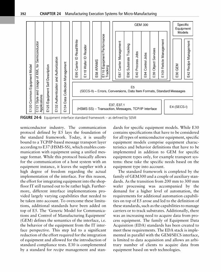
semiconductor industry. The communicationprotocol defined by E5 lays the foundation ofthe standard framework. Today, it is usuallybound to a TCP/IP-based message transport layeraccording to E37 (HSMS-SS), which enables com-munication with equipment using a unified mes-sage format. While this protocol basically allowsfor the communication of a host system with anequipment instance, it leaves the supplier with ahigh degree of freedom regarding the actualimplementation of the interface. For this reason,the effort for integrating equipment into the shop-floor IT still turned out to be rather high. Further-more, different interface implementations pro-vided largely varying capabilities that needed tobe taken into account. To overcome these limita-tions, additional standards have been added ontop of E5. The ‘Generic Model for Communica-tions and Control of Manufacturing Equipment’(GEM) defines the semantics of the interface, i.e.the behavior of the equipment from the IT inter-face perspective. This step led to a significantreduction of the effort required for the integrationof equipment and allowed for the introduction ofstandard compliance tests. E30 is complementedby a standard for recipe management and stan-
dards for specific equipment models. While E30contains specifications that have to be consideredfor all types of semiconductor equipment, specificequipment models comprise equipment charac-teristics and behavior definitions that have to beimplemented in addition to GEM for specificequipment types only, for example transport sys-tems: these take the specific needs based on theequipment type into account.
The standard framework is completed by thefamily of GEM300 and a couple of auxiliary stan-dards. As the transition from 200 mm to 300 mmwafer processing was accompanied by thedemand for a higher level of automation, therequirements for additional automation capabili-ties on top of E5 arose and led to the definition ofthese standards, such as the capabilities tomanagecarriers or to track substrates. Additionally, therewas an increasing need to acquire data from pro-cess equipment. The family of Equipment DataAcquisition (EDA) standards has been created tomeet these requirements. The EDA stack is imple-mented in parallel with the GEM/SECS interface,is limited to data acquisition and allows an arbi-trary number of clients to acquire data fromequipment based on web technologies.
FIGURE 24-6 Equipment interface standard framework – as defined by SEMI
392 CHAPTER 24 Manufacturing Execution Systems for Micro-Manufacturing
CONCLUSIONS
Today, it is virtually unthinkable to operate state-of-the-art manufacturing facilities without a vari-ety of IT systems supporting production. Severalclasses of IT systems can be found over the differ-ent layers of these facilities – from enterpriseresource planning systems as an example on theenterprise management layer down to program-mable logic controller-based applications on themanufacturing processes layer. The term MESusually refers to a collection of integrated soft-ware applications that is located between thosetwo layers – on the manufacturing operationsand control layer. On the one hand the MESensures the right level of information transferbetween upper and lower layers and thereby sup-ports the integration of processes on the shopfloor into the overall business process framework.On the other hand the MES provides a rich set offunctionalities to optimize operations on the shopfloor in different dimensions, such as productquality, resource utilization and the adherenceto delivery dates. A variety of standards have beencreated in different industries to enable and sim-plify the set-up of theMES environment. Lookingat the potential provided by an MES, the rele-vance of this topic in the area of micro-manufacturingwill continue to grow in the future.
REFERENCES
[1] Enterprise-control system integration, Part I: Modelsand terminology. ANSI/ISA-S95.00.01-2000. Instru-ment Society of America, Research Triangle Park,NC, USA (2000).
[2] Manufacturing execution systems – production man-agement systems. VDI 5600 Blatt 12006-08. VereinDeutscher Ingenieure. Published by: Beuth VerlagGmbH, 10772 Berlin, Germany (2006).
[3] Specification for definition and measurement ofequipment reliability, availability and maintainabil-ity (RAM). SEMI E10. Semiconductor Equipmentand Materials International, 3081 Zanker Road,San Jose, CA, USA (2004).
[4] Specification for definition and measurement ofequipment productivity. SEMI E79. SemiconductorEquipment and Materials International, 3081 Zan-ker Road, San Jose, CA, USA (2006).
[5] Semiconductor Equipment and Materials Interna-tional – SEMI [Last access: 30.10.2007]; http://www.semi.org.
[6] Manufacturing Enterprise Solutions Association –MESA International [Last access: 30.10.2007];http://www.mesa.org.
[7] Internet Society – ISOC [Last access: 30.10.2007];http://www.isoc.org/.
[8] Williams, T. J., (ed.), A reference model for com-puter integrated manufacturing (CIM), a descriptionfrom the viewpoint of industrial automation, Instru-ment Society of America, Research Triangle Park,NC, USA (1989).
[9] Anonymous, Enterprise-control system integration,Part II: Object model attributes. ANSI/ISA–S95.00.02-2001. Instrument Society of America,Research Triangle Park, NC, USA (2001).
[10] Anonymous, Enterprise-control system integration,Part III: Activity models of manufacturing operationsmanagement. ANSI/ISA-S95.00.03-2005. Instru-ment Society of America, Research Triangle Park,NC, USA (2005).
[11] The OPC Foundation [Last access: 30.10.2007];http://www.opcfoundation.org/.
[12] M.Meier, P. Dreiss and J. Seidelmann, Potentials andlimitations of standardization of shop floor IT basedon examples from semiconductor industry, PPSMan-agement 12 (2007) 4, Gito Verlag mbH, Klixstr. 1 A,13403 Berlin, Germany (2007).
CHAPTER 24 Manufacturing Execution Systems for Micro-Manufacturing 393