mi7 central office engineering and planning guide · mi7 central office engineering and planning...
TRANSCRIPT
Mi7 Central Office Engineering and Planning Guide
Software Release 1.6October 28, 2004
Mahi Networks, Inc.1039 N. McDowell Blvd.Petaluma, CA. 94954| USAhttp://www.mahinetworks.com
Copyright © 2001-2004 By Mahi Networks, Inc. All Rights Reserved.
Proprietary and Confidential Information of Mahi Networks, Inc. Mahi Part # 0900-0049-01

I Mi7 Central Office Engineering and Planning Guide
Tel: (707) 283-1000Fax: (707) 283-1299
THE SPECIFICATIONS AND INFORMATION REGARDING THE PRODUCTS IN THIS MANUAL ARE SUBJECT TO CHANGE WITHOUT NOTICE. ALL STATEMENTS, INFORMATION, AND RECOMMENDATIONS IN THIS MANUAL ARE BELIEVED TO BE ACCURATE.
This material is protected by the copyright laws of the United States and other countries. It may not be reproduced, distributed, or altered in any fashion, by any entity, except in accordance with applicable agreements, contracts, or licences, without the express written consent of Mahi Networks, Inc.
Limited WarrantyMahi Networks, Inc. provides a limited warranty to this product as set forth in the license and/or purchase agreement pursuant to which this product was delivered under.
TrademarksADM-on-a-Wavelength, AOT, ATN, Automated Optical Transport, Automated Transport Networking, Banded Strandwidth, Direct Connect, Dx7, ESR, Extended Service Reach, High Performance Network Architectures, Judicious Integration of WDM and TDM, Mahi, MCAS, MCTS, MET, Metro Ethernet Transport, Mi7, Mission7, Mission7 Central, Mix-and-Match Optical Layer Protection, Multi-Service Core Aggregation System, Multi-Service Core Transport System, No Constraints - No Compromises, ONX, Optical Node Interconnect, Powered by Versicolor, RapidADD, RPR-on-a-Wavelength, Sensible Integration of SONET and WDM, SONET Ring Aggregation, SONET Ring Integration, SRA, SRAplus, SRI, Versicolor, VersiNET Vx7, Wavelength Power, SONET Simplicity, and Zero Disruption Migration are trademarks or registered trademarks of Mahi Networks, Inc. All other company and product names are trademarks or registered trademarks of their respective owners.
I-ii © 2001-2004 Mahi Networks, Inc. All Rights Reserved.
Proprietary and Confidential Information of Mahi Networks, Inc. Mahi Part # 0900-0049-01
Revision History
Revision Date Comments Source Control Document Number
Draft 08/30/2004
01 10/28/2004 Initial release 9160-0068, rev02
© 2001-2004 Mahi Networks, Inc. All Rights Reserved. II-i
Proprietary and Confidential Information of Mahi Networks, Inc. Mahi Part # 0900-0049-01

II Mi7 Central Office Engineering and Planning Guide
II-ii © 2001-2004 Mahi Networks, Inc. All Rights Reserved.
Proprietary and Confidential Information of Mahi Networks, Inc. Mahi Part # 0900-0049-01
Table of Contents
1 About This ManualGuide Objectives ..................................................................... 1-1Audience ................................................................................ 1-1Installation Conventions and Nomenclature ............................... 1-1
Text Conventions .......................................................................... 1-1Mi7 Documentation Set ............................................................ 1-2Obtaining Documentation ........................................................ 1-4Obtaining Technical Assistance ................................................. 1-4
Repair and Return ......................................................................... 1-4Document Feedback ................................................................ 1-4Contacting Mahi Networks ........................................................ 1-5
2 Observing Safety GuidelinesIntroduction ............................................................................ 2-1Installation Information and General Cautions ............................ 2-2Using Optical Fibers ................................................................. 2-2
Handling Optical Fibers .................................................................. 2-3Repairing Optical Fibers ................................................................. 2-4
Working with Power ................................................................ 2-4Dissipating Static Electricity ...................................................... 2-5Preventing Line Card Damage .................................................. 2-5
Handling, Installing, or Replacing Line Cards ................................... 2-6Storing Line Cards ......................................................................... 2-6Transporting Line Cards ................................................................. 2-8
3 PreparationIntroduction ............................................................................ 3-1Overview of the Mi7 ................................................................. 3-2Rack Face Drawings ................................................................. 3-4
Configuration 1: High Density ................................................... 3-4Configuration 2: Low Density (Three Racks) ............................... 3-5Configuration 3: Low Density (Five Racks) .................................. 3-6
Floor Plan ............................................................................... 3-6Cables, Wires, and Terminations ............................................... 3-8
© 2001-2004 Mahi Networks, Inc. All Rights Reserved. III-i
Proprietary and Confidential Information of Mahi Networks, Inc. Mahi Part # 0900-0049-01
III Mi7 Central Office Engineering and Planning Guide
PDU Wire Gauges .......................................................................... 3-8Mechanical Requirements .......................................................3-13
Rack Requirements ......................................................................3-13Hardware ....................................................................................3-13
Line Card Placement Considerations ........................................3-13Line Card to Fabric Port Card Connections .....................................3-13Slot Assignment Scheme with Octal OC-48 Line Cards ....................3-16
Special Requirements .............................................................3-16Building Requirements ..................................................................3-16
Shipping Pallets ......................................................................3-16Cable Management .................................................................3-16Spares Storage .......................................................................3-16
Environmental Requirements .........................................................3-17Electrical Requirements ................................................................3-17Timing Requirements ...................................................................3-17Space Requirements......................................................................3-17Rack Mounting Options..................................................................3-19
Shelf Front Mount Configuration ...............................................3-19Shelf Mid-Mount Configuration ..................................................3-20PDU Front Mount Configuration.................................................3-21
Handling Requirements .................................................................3-22Inserting Cards .......................................................................3-22Extracting Cards.......................................................................3-23
Tools and Equipment...............................................................3-24Crimping Tools .............................................................................3-24Parts Required (but not shipped) ...................................................3-25
Preparation and Installation .....................................................3-26Site Preparation ...........................................................................3-26Installation Approach ...................................................................3-26
Mechanical Descriptions...........................................................3-27Racks ...........................................................................................3-28Shelves .......................................................................................3-28
X3 Fabric Shelf ........................................................................3-28Primary Line Card Shelf ...........................................................3-28Expansion Line Card Shelf ........................................................3-28Power Distribution Unit ............................................................3-28
4 ConfigurationsCircuit Breaker Configurations ................................................... 4-2Shelf Cabling Schedule ............................................................ 4-3Office Facility Power Recommendations .................................... 4-4Wire and Cable Routing ........................................................... 4-5
III-ii © 2001-2004 Mahi Networks, Inc. All Rights Reserved.
Proprietary and Confidential Information of Mahi Networks, Inc. Mahi Part # 0900-0049-01
Mi7 Central Office Engineering and Planning Guide III
MAT Layouts ........................................................................... 4-5The Important Role of Card Blanks ........................................... 4-7
A Mi7 SpecificationsSystem Specifications .............................................................. A-1
System Architecture ...................................................................... A-1Standards Compliance .................................................................... A-2Network Controller ........................................................................ A-2
NCC on PLCS ........................................................................... A-3NCC on ELCS ........................................................................... A-3
System Facility Density .................................................................. A-3System Management ..................................................................... A-4Supported Services ....................................................................... A-4
Equipment Specifications ......................................................... A-4Hardware Components .................................................................. A-4Mi7 Line Card Specifications............................................................ A-8
Optical Interface Specifications ................................................. A-9Line Cards (SDX and MSX) ............................................................. A-9
OC-48 and OC-192 ITU Grid Optical Parameters ....................... A-11ITU Grid Optics Channel Plan .................................................. A-12
Line Cards (GbE) ......................................................................... A-13HVAC Specifications................................................................ A-15
Environmental Specifications ........................................................ A-15
B LED SpecificationsIntroduction ............................................................................ B-1LED Displays and Behaviors ...................................................... B-1
Shelf LED Displays ........................................................................ B-2PLCS LED Displays and Behaviors .............................................. B-2ELCS and X3FS LED Displays and Behaviors ................................ B-4
Line Card LEDs Displays and Behaviors ............................................ B-5OC-3/STM-1 ............................................................................ B-5OC-3/12 / STM-1/4 .................................................................. B-6OC-48/STM-16 (Octal) ............................................................... B-7OC-48/STM-16, OC-192/STM-64 and OC-192/STM-64 ITU C-Band Tunable.................................................................................... B-8GbE.......................................................................................... B-9PPX........................................................................................ B-10Network Controller Card 2........................................................ B-11Fabric Port Card ...................................................................... B-12Fabric Controller Card.............................................................. B-13XC Switch Matrix Card ............................................................. B-14
© 2001-2004 Mahi Networks, Inc. All Rights Reserved. III-iii
Proprietary and Confidential Information of Mahi Networks, Inc. Mahi Part # 0900-0049-01
III Mi7 Central Office Engineering and Planning Guide
C List of Acronyms
D Index
III-iv © 2001-2004 Mahi Networks, Inc. All Rights Reserved.
Proprietary and Confidential Information of Mahi Networks, Inc. Mahi Part # 0900-0049-01
1 About This Manual
Guide ObjectivesThis guide details information necessary for planning and engineering a Central Office installation of the Mahi Networks Mi7 platform.
AudienceThis book is for engineers and network planners who have a broad understanding of networks, configuration principles, and installation procedures. In writing this document, Mahi Networks assumes that you have an understanding of the Internet, networking principles, networking configuration, and experience in access and inter-network administration.
Installation Conventions and NomenclatureThe Mi7 is primarily a front-access node. Unless otherwise stated, all illustrations are front view.
In this manual the term cable refers to fiber cable, CAT-5 Ethernet cable, or large diameter copper wire used in the delivery of power to the racks and to the shelves (up to 750CFM).
The term conductor refers to copper wire smaller than 14 AWG.
The term card refers to printed circuit boards.
Acronyms are spelled out at their first occurrence in a chapter, with the acronym following in parentheses. Thereafter, the acronym is used without parentheses, and if used in plural form, with a lower-case s.
Text ConventionsThis document uses the following icons and their related text:
DANGER: Text with this icon describes actual or potential situations in which serious bodily harm is possible.
© 2001-2004 Mahi Networks, Inc. All Rights Reserved. Guide Objectives 1-1
Proprietary and Confidential Information of Mahi Networks, Inc. Mahi Part # 0900-0049-01
1 About This Manual Mi7 Central Office Engineering and Planning Guide
Mi7 Documentation SetThe Mahi Networks Mi7 Software Release 1.6 document set consists of:
• MI7 GENERAL SYSTEM DESCRIPTION - contains general information about the applications, features, architecture and management of the Mahi Networks Mi7™ Multi-Service Core Aggregation System (MCAS). This book describes the technology integration that converges the functionality of multiple SONET/SDH Add-Drop Multiplexers (ADM), a Broadband Digital Cross Connect System (BB-DCS), and a Layer 2 packet switch under one system. The audience for this book includes network planners, engineers and administrators. A high level understanding of networking principles, technologies and protocols is helpful in understanding the material presented in this document, but not required.
• MI7 NETWORK ENGINEERING AND PLANNING GUIDE - contains information necessary for planning and engineering networks with the Mi7 platform. This book is for engineers and network planners who have a strong understanding of networks, networking principles, and network configuration procedures. It includes Mi7 component descriptions and specifications, information on SONET and Broadband Digital Cross Connect functionality, and Metro Ethernet Transport and Passive DWDM applications. It also describes user administration configurations and considerations.
• MI7 CENTRAL OFFICE ENGINEERING AND PLANNING GUIDE - contains information necessary for planning and engineering a Central Office installation of the Mi7 platform. This book is for engineers and network planners who have a broad understanding of networks, configuration principles, and installation procedures. It includes Mi7 component descriptions and specifications as well as information on physical plant considerations (floor plan, cabling, equipment and electrical requirements). It also describes site configurations and layouts as well as safety guidelines.
• MI7 INSTALLATION GUIDE - contains instructions for site preparation and installation of an Mi7 node. It includes instructions for site verification, unpacking equipment, installing the
WARNING: Used to warn of situations in which minor or moderate bodily harm is possible.
CAUTION: Text with this icon describes possible damage to equipment or software, or informs you that service might be affected.
NOTE: Text with this icon alerts you to take note. It contains helpful information.
1-2 Mi7 Documentation Set © 2001-2004 Mahi Networks, Inc. All Rights Reserved.
Proprietary and Confidential Information of Mahi Networks, Inc. Mahi Part # 0900-0049-01

Mi7 Central Office Engineering and Planning Guide 1 About This Manual
Mi7 shelves and Power Distribution Unit in the rack, installing line cards, controllers, and switch fabric cards, and installing all copper and fiber cabling. The audience for this book includes personnel involved in site preparation, the Power Crew, and the Installation Crew.
• MI7 UNIT HARDWARE DESCRIPTION - contains Mahi Networks Mi7 Multi-Service Core Aggregation System (MCAS) hardware component descriptions and specifications. It includes descriptions of the major components and their functionality, management and optical interfaces, timing, breakers, dimensions, and power requirements. The audience for this book includes engineers, network architects, system and network administrators, personnel involved in site preparation, and those involved in ordering Mi7 parts.
• MI7 PROCEDURES GUIDE - contains step-by-step instructions on using the Transaction Language 1 (TL1) interface and Command Line Interface (CLI) to operate, administer, provision, and manage functionality of the Mahi Networks Mi7. This guide describes usage guidelines and application examples for SONET transport features and OSI Routing Protocols (IS-IS) of the SONET OSI DCC. It also describes guidelines and examples for Ethernet (GbE and Ethernet over SONET) features and IP Routing Protocols (OSPF) of the SONET IP DCC. It is written for system and network administrators who are familiar with TL1, and/or using a CLI, and have a broad understanding of networks, networking principals, and network configuration procedures.
• MI7 WEB REFERENCE GUIDE - describes the tasks and procedures used to operate and maintain a single Mi7 network element. The Mi7 Web management interface provides system operators the means to manage the transport (SONET), Ethernet (GbE and Ethernet over SONET), and DCC routing protocol attributes of the Mi7. The Mi7 Web management agent provides a Web browser-based alternative to CLI and TL1 for operating an Mi7 network element. The primary audience for this guide includes local and remote craft personnel.
• MI7 CLI COMMAND REFERENCE - contains the structure and parameters of commands for the Mahi Networks Mi7 Command Line Interface (CLI). Commands in this book are used to administer, provision, and operate the Mi7 Ethernet (GbE and Ethernet over SONET) features and IP Routing Protocols (OSPF) of the SONET IP DCC. This book is written for system and network administrators who are familiar with CLI commands and have a broad understanding of networks, networking principles, and network configuration procedures.
• MI7 TL1 COMMAND REFERENCE - describes the structure and parameters of Transaction Language 1 (TL1) messages. These messages are to be used for the operation, administration, and surveillance management of the Mahi Networks Mi7. The TL1 services provide system operators and administrators the means to manage the transport (SONET) attributes of the Mi7, including OSI Routing Protocols (IS-IS) of the SONET OSI DCC. This book is written for system and network administrators who are familiar with TL1 and have a broad understanding of networks, networking principles, and network configuration procedures.
• MISSION7 CENTRAL REFERENCE GUIDE - describes the tasks and procedures used to operate and maintain a network of Mi7 network elements with the Mahi Networks Mission7 Central management system. The primary audience for this guide includes Network Operations Center (NOC) personnel, including system administrators, and surveillance, provisioning, and maintenance personnel.
• MI7 ALARM AND TROUBLESHOOTING GUIDE - describes the SONET alarms and events generated by the Mi7. The guide lists the definition, default severity, cause, service impact, and recovery process for each alarm.
© 2001-2004 Mahi Networks, Inc. All Rights Reserved. Mi7 Documentation Set 1-3
Proprietary and Confidential Information of Mahi Networks, Inc. Mahi Part # 0900-0049-01
1 About This Manual Mi7 Central Office Engineering and Planning Guide
Obtaining DocumentationMahi Networks provides both electronic and printed documentation with its products. The electronic documentation in the form of a CD-ROM contains the latest information on the product. CD-ROMs are shipped with Mahi Networks hardware, with software upgrades, or can be ordered separately. The hard copy documentation is updated for all major releases. Information on software enhancements and upgrades occurring between releases will be shipped to you in the form of release notes and configuration notes.
To order documentation, call Mahi Networks Sales Support at: (866) 886-6244.
Obtaining Technical AssistanceMahi Networks Technical Assistance Center (TAC) offers full 24/7 technical support at no charge for a Mahi Networks product that is under warranty or covered by a maintenance contract. This includes a fully staffed Call Center, Technical Assistance Center, and Field Support organization for critical, immediate on-site support.
• For e-mail support, send a message to: [email protected]. • For telephone assistance, please call Mahi Networks Global Customer Service at:
(866) MAHI-NOW (866-624-4669). For service affecting issues, technical assistance is available 24 hours a day, 7 days a week. For non-service affecting issues, call between 4:00 A.M. and 7:00 P.M., U.S. Pacific Time.
Repair and ReturnFor hardware repair and return information, contact Mahi Networks Global Customer Service at: (866) MAHI-NOW (866-624-4669).
Document FeedbackMahi Networks appreciates comments and suggestions about our documentation. You can give feedback on this document in one of the following ways:
• E-mail: [email protected]• Mail:
Technical Documentation Department
Mahi Networks
1039 North McDowell Boulevard
Petaluma, CA 94954
Fax: (707) 283-1299
• Call Sales Support at: (866)-886-6244.
1-4 Obtaining Documentation © 2001-2004 Mahi Networks, Inc. All Rights Reserved.
Proprietary and Confidential Information of Mahi Networks, Inc. Mahi Part # 0900-0049-01
Mi7 Central Office Engineering and Planning Guide 1 About This Manual
Contacting Mahi NetworksContact Mahi Networks in any of the following ways:
• Main (switchboard) telephone: 707-283-1000• Customer Service telephone: (866) MAHI-NOW (866-624-4669)• Sales Support telephone: (866)-886-6244• World Wide Web: www.mahinetworks.com• E-mail:
– Documentation - [email protected]– Sales - [email protected]– Technical Support - [email protected]
• Mail: 1039 North McDowell Boulevard, Petaluma, CA 94954
© 2001-2004 Mahi Networks, Inc. All Rights Reserved. Contacting Mahi Networks 1-5
Proprietary and Confidential Information of Mahi Networks, Inc. Mahi Part # 0900-0049-01

1 About This Manual Mi7 Central Office Engineering and Planning Guide
1-6 Contacting Mahi Networks © 2001-2004 Mahi Networks, Inc. All Rights Reserved.
Proprietary and Confidential Information of Mahi Networks, Inc. Mahi Part # 0900-0049-01

2 Observing SafetyGuidelines
IntroductionThis chapter highlights safety guidelines you should follow for personal safety and for the correct handling and operation of equipment.
Mahi Networks documentation contains precautionary messages and safety procedures that refer to specific tasks or conditions. See “Text Conventions” on page 1-1 for samples of the “precautionary message” formats specific to this document. You must read and follow all the precautionary messages before you work on the equipment.
What’s Inside?“Installation Information and General Cautions” on page 2-2
“Using Optical Fibers” on page 2-2
“Working with Power” on page 2-4
“Dissipating Static Electricity” on page 2-5
“Preventing Line Card Damage” on page 2-5
© 2001-2004 Mahi Networks, Inc. All Rights Reserved. Introduction 2-1
Proprietary and Confidential Information of Mahi Networks, Inc. Mahi Part # 0900-0049-01
2 Observing Safety Guidelines Mi7 Central Office Engineering and Planning Guide
Installation Information and General CautionsInstallation and operations personnel should be aware of the following information:
• Equipment is intended for installation in a restricted access location.• Only qualified service personnel are allowed to service this system.• A readily accessible disconnect device must be incorporated in the building installation
wiring.• When requested, instructions and equipment marking related to safety shall be in a
language that is acceptable in the country in which the equipment is to be installed.• This device complies with Part 15 of the FCC rules. Operation is subject to the following
conditions:– This device may not cause harmful interference.– This device must accept any interference received, including interference that may
cause undesired operation.• The standards that dictate our optical safety labeling requirements are IEC 60825-1
(Edition 1.2 2001-08), FDA 21 CFR 1040.10 (4-1-97 Edition), and FDA Regulation CDRH Laser Notice No. 50 dated July 26, 2001.
• The following laser safety standards classify the Mi7:– Class 1M LASER PRODUCT (IEC 60825-1 2001-01) – Class I LASER PRODUCT (21CFR 1040.10 and 1040.11)
• Viewing the laser output with certain optical instruments (for example, eye loupes, magnifiers, and microscopes) within a distance of 100 mm may pose an eye hazard.
Using Optical FibersOptical fibers are either single mode or multi-mode. The following information applies to all optical fibers.
DANGER: Use of controls or adjustments or performance of procedures other than those specified herein may result in hazardous radiation exposure.
DANGER: Risk of laser radiation exposure.
2-2 Installation Information and General Cautions © 2001-2004 Mahi Networks, Inc. All Rights Reserved.
Proprietary and Confidential Information of Mahi Networks, Inc. Mahi Part # 0900-0049-01
Mi7 Central Office Engineering and Planning Guide 2 Observing Safety Guidelines
Handling Optical FibersWhen you work with optical fibers, take the following precautions:
• Wear safety glasses when you install optical fibers.
• Never look into an active optical fiber or an optical connector opening of an active or powered-up unit.
• Prevent direct exposure to optical fiber ends or optical connector ends where you can directly access the laser signal.
• Clean your hands after you handle optical fibers. Small pieces of glass are not always visible and contact with your eyes may be harmful.
• Do not handle pieces of optical fiber with your fingers. Use tweezers or adhesive tape to lift and discard any loose optical fiber ends.
• Wear rubber gloves when you clean optical connectors. The gloves prevent direct contact with the isopropyl alcohol and prevent contamination of the ferrules with skin oils.
• Place all optical fiber clippings in a plastic container provided for that purpose. • Handle optical fibers with caution. Place the optical fibers in a safe location during
installation. • Protect all optical fiber connectors with clean dust caps at all times.• Follow the manufacturer instructions when you use an optical test set. Incorrect
calibration or control settings can create hazardous levels of radiation.
DANGER: Risk of eye injury.Do not look directly into the optical beam. Invisible light can severely damage your eyes. Keep all optical connectors capped.
CAUTION: Risk of damage to line cards.Never connect or disconnect an optical fiber on an active or powered up optical amplifier. To connect or disconnect an optical fiber, place the optical amplifier out-of-service (OOS), unseat the optical amplifier, then connect or disconnect the optical fiber. High optical power levels can damage line cards if improper connections are made.
WARNING: If you have a piece of glass in your eye, get medical assistance immediately.
© 2001-2004 Mahi Networks, Inc. All Rights Reserved. Using Optical Fibers 2-3
Proprietary and Confidential Information of Mahi Networks, Inc. Mahi Part # 0900-0049-01
2 Observing Safety Guidelines Mi7 Central Office Engineering and Planning Guide
Repairing Optical FibersWhen an accidental break occurs in the optical fiber, do the following:
• Report the location of the damaged optical fiber to both the central office and field repair personnel.
• Power down all laser sources to the optical fiber and disconnect the remote optical fiber end from the laser sources. See “Handling Optical Fibers” on page 2-3 before you disconnect any optical fiber from a laser source. The sources can be in a central office, on subscriber premises, or in a remote location.
Working with Power
When you install power feeds to the product input power terminals or perform routing power maintenance, do the following:
• Read and understand the power procedures you perform.• Take the necessary precautions and use the correct insulated tools to perform any tasks.• Remove or cover metal objects, such as jewelry, watches, buttons, or buckles on your body
or clothing.A tripped circuit breaker indicates that an over-current event has probably occurred. Before resetting the circuit breaker, service personnel must:
• Determine the parts of the product fed by the circuit breaker.• Determine if there are any obvious causes for the trip occurring in the affected parts and
associated wiring. • Verify that the power distribution unit element configuration complies with the installation
instructions.After you reset any previously tripped circuit breaker, wait near the product for at least one minute to ensure that the fault clears and the product returns to normal operation.
When you remove the breaker module, follow the instructions provided on the product label.
DANGER: Risk of high power current surge.
DANGER: Risk of electrical shock.Read and understand the power procedures you are performing. Take necessary precautions and use the appropriate insulated tools when working with power.
2-4 Working with Power © 2001-2004 Mahi Networks, Inc. All Rights Reserved.
Proprietary and Confidential Information of Mahi Networks, Inc. Mahi Part # 0900-0049-01
Mi7 Central Office Engineering and Planning Guide 2 Observing Safety Guidelines
Dissipating Static ElectricityThe level of static electricity increases on your body when you move around or come into contact with other charged surfaces. Excessive levels of static electricity can damage equipment. Wear a heel grounder (that attaches to your leg and foot), or an antistatic wrist-strap, or another personal grounding device, when you work on any of the following:
• network element shelves (including the metal frame and cover)• cables connected to line cards• line cards• push-buttons, switches or connectors on interface panels
Any one of the previously mentioned grounding devices dissipates electrostatic charges to the ground quickly. Use grounding devices correctly to eliminate the Electrostatic Discharge (ESD) threat you pose to the equipment.
When you wear an antistatic wrist-strap and a heel grounder, make sure the grounding straps are in contact with a moist part of your skin. The grounding cord of your wrist-strap should be connected to the grounding plug on a grounded fixture of the product you are working on. Grounded fixtures are accessible on Mahi Networks Mi7 products.
To ensure the best ESD protection:
• Check grounding straps with an appropriate test station, if available.• Install bays on conductive floor coverings.• Provide conductive shoes, antistatic wrist-straps, or heel grounders to all personnel
working on the equipment.
Preventing Line Card DamageAll line cards are subject to damage by rough handling or by electrostatic discharge. The following section shows how to prevent damage to line cards.
NOTE: If you are working in a “non-lab” environment (floor is not ESD), then it is only necessary to wear antistatic wrist-straps.
© 2001-2004 Mahi Networks, Inc. All Rights Reserved. Dissipating Static Electricity 2-5
Proprietary and Confidential Information of Mahi Networks, Inc. Mahi Part # 0900-0049-01
2 Observing Safety Guidelines Mi7 Central Office Engineering and Planning Guide
Handling, Installing, or Replacing Line CardsWhen you handle, install, or replace line cards, take the following precautions:
• Wear an antistatic wrist-strap or another personal grounding device before you remove a line card from its package or from the shelf.
• Protect line cards that are not in active use on the shelf by storing each one separately in a shielded box.
• Handle each line card by the faceplate or stiffener.• Do not touch the solder side of the line card, the pin connector, or the components.• Do not stack line cards on or against each other.• Inspect all pin connectors on each line card for damage before use.• Inspect all line cards for damage before inserting into shelf.• Do not force line cards into their packaging material.• Do not force line cards into their positions in the shelf.• Protect all optical connectors of the transmit and receive optical line cards with clean dust
caps at all times.• Allow each line card to reach room temperature before you insert it into the shelf.
Storing Line CardsLeave spare line cards in the original shielded containers until needed. To prevent damage to stored line cards, follow standard procedures for preventing the following:
• accumulation of dirt or dust on the pin connectors• damage to the printed-circuit board or its components• warpage to printed-circuit boards stored in areas where the humidity can exceed 95% and
the temperature can exceed 70°C.
DANGER: Risk of personal injury.Weight of line cards can exceed 10 kg (25 lbs). Use caution when handling line cards, especially if you remove the line cards from a high shelf on the bay.
DANGER: Hot surfaces can cause burns. When handling these line cards, take the necessary precautions and read the specific instructions for that line card. For example, wear insulating gloves when you remove these line cards.
2-6 Preventing Line Card Damage © 2001-2004 Mahi Networks, Inc. All Rights Reserved.
Proprietary and Confidential Information of Mahi Networks, Inc. Mahi Part # 0900-0049-01
Mi7 Central Office Engineering and Planning Guide 2 Observing Safety Guidelines
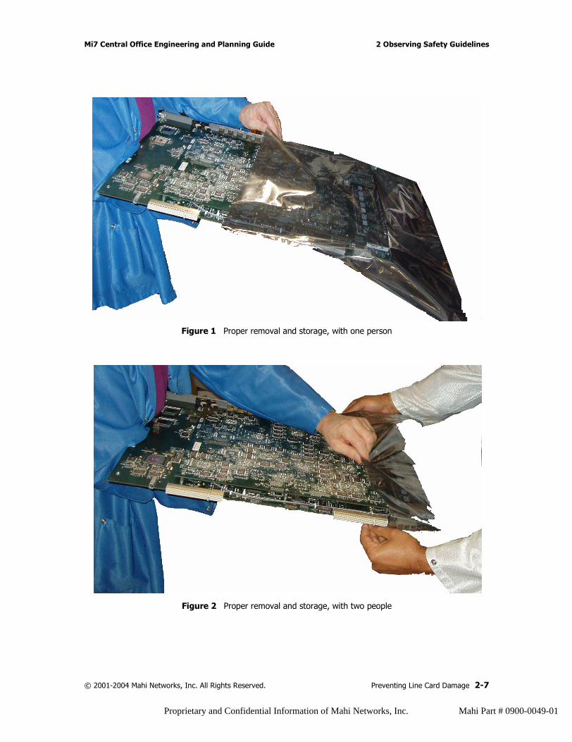
Figure 1 Proper removal and storage, with one person
Figure 2 Proper removal and storage, with two people
© 2001-2004 Mahi Networks, Inc. All Rights Reserved. Preventing Line Card Damage 2-7
Proprietary and Confidential Information of Mahi Networks, Inc. Mahi Part # 0900-0049-01
2 Observing Safety Guidelines Mi7 Central Office Engineering and Planning Guide
Transporting Line CardsWhen transporting line cards, pack each in its original shielded container and padding, or in a shielded bag. If you lose the original material, use another approved Mahi Networks shielded container. Shipping in any other packaging may void the warranty.
2-8 Preventing Line Card Damage © 2001-2004 Mahi Networks, Inc. All Rights Reserved.
Proprietary and Confidential Information of Mahi Networks, Inc. Mahi Part # 0900-0049-01
3 Preparation
IntroductionThis chapter highlights the safety requirements and site preparation for the installation of a Mahi Networks Mi7.
What’s Inside?“Overview of the Mi7” on page 3-2
“Rack Face Drawings” on page 3-4
“Floor Plan” on page 3-6
“Cables, Wires, and Terminations” on page 3-8
“Mechanical Requirements” on page 3-13
“Line Card Placement Considerations” on page 3-13
“Special Requirements” on page 3-16
“Tools and Equipment” on page 3-24
“Preparation and Installation” on page 3-26
“Mechanical Descriptions” on page 3-27
© 2001-2004 Mahi Networks, Inc. All Rights Reserved. Introduction 3-1
Proprietary and Confidential Information of Mahi Networks, Inc. Mahi Part # 0900-0049-01
3 Preparation Mi7 Central Office Engineering and Planning Guide
Overview of the Mi7The basic Mi7 system consists of an X3 Fabric Shelf (X3FS), a Primary Line Card Shelf (PLCS), and a Power Distribution Unit (PDU), all of which can be installed in a single seven-foot rack. The system can optionally be expanded with an Expansion Line Card Shelf (ELCS) and a PDU in a second rack. The mounting brackets for each shelf and PDU are adaptable to both domestic and ETSI rack dimensions. Shelves can be mounted in WECO (2") or EIA (1.75") and ETSI.
An Mi7 installation requires separate redundant -48V power inputs to the PDU for each shelf in a rack. The PDU, in turn, powers each shelf.
Six fans (two fan trays with three fans each) cool each shelf. The fans are temperature controlled and vary their speed automatically. Each fan tray comes with an air filter, reducing the chance of particle intake.
Craft access is achieved with a computer connected to ports on the active Network Controller Card (NCC) on the PLCS. Management access is achieved through connectors in the Maintenance, Alarm, and Timing (MAT) panel in the upper area of the PLCS.
Optical traffic input and output is through the line cards contained in the PLCS and ELCS. The PLCS and ELCS each have sixteen slots used for line cards, and two slots for NCC cards. Line cards support 1, 4, 8, or 16 optical facilities (depending on line card type).
Shelves are interconnected with fiber optic cables and CAT-5 electrical cables, which are provided by Mahi Networks, and are connected during installation.
See “Line Card Placement Considerations” on page 3-13 for information on other cabling and wiring.
3-2 Overview of the Mi7 © 2001-2004 Mahi Networks, Inc. All Rights Reserved.
Proprietary and Confidential Information of Mahi Networks, Inc. Mahi Part # 0900-0049-01
Mi7 Central Office Engineering and Planning Guide 3 Preparation
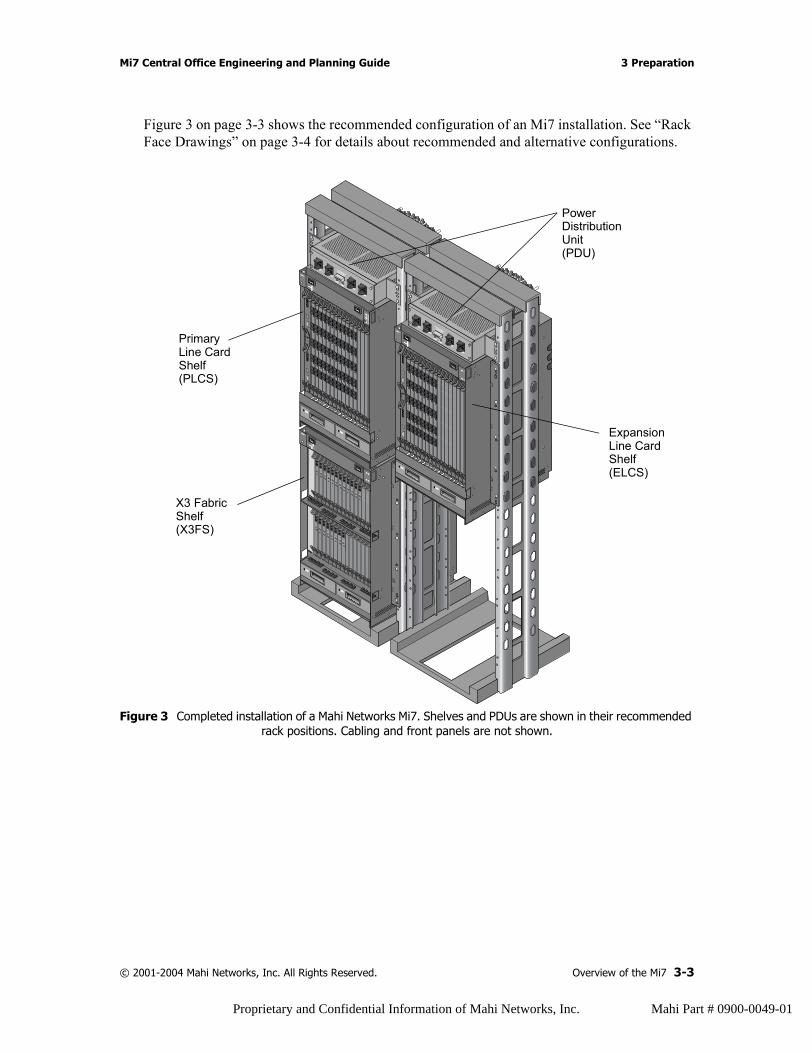
Figure 3 on page 3-3 shows the recommended configuration of an Mi7 installation. See “Rack Face Drawings” on page 3-4 for details about recommended and alternative configurations.
Figure 3 Completed installation of a Mahi Networks Mi7. Shelves and PDUs are shown in their recommended rack positions. Cabling and front panels are not shown.
..........
......
.........
......
..........
......
.........
......
..........
......
PC
LCS TX
LCS RX
TX LINK
RX LINK
PC
LCS TX
LCS RX
TX LINK
RX LINK
PC
LCS TX
LCS RX
TX LINK
RX LINK
PC
LCS TX
LCS RX
TX LINK
RX LINK
PC
LCS TX
LCS RX
TX LINK
RX LINK
PC
LCS TX
LCS RX
TX LINK
RX LINK
PC
LCS TX
LCS RX
TX LINK
RX LINK
PC
LCS TX
LCS RX
TX LINK
RX LINK
PC
LCS TX
LCS RX
TX LINK
RX LINK
PC
LCS TX
LCS RX
TX LINK
RX LINK
PC
LCS TX
LCS RX
TX LINK
RX LINK
PC
LCS TX
LCS RX
TX LINK
RX LINK
PC
LCS TX
LCS RX
TX LINK
RX LINK
PC
LCS TX
LCS RX
TX LINK
RX LINK
PC
LCS TX
LCS RX
TX LINK
RX LINK
PC
LCS TX
LCS RX
TX LINK
RX LINK
PC
LCS TX
LCS RX
TX LINK
RX LINK
PC
LCS TX
LCS RX
TX LINK
RX LINK
PC
LCS TX
LCS RX
TX LINK
RX LINK
PC
LCS TX
LCS RX
TX LINK
RX LINK
PC
LCS TX
LCS RX
TX LINK
RX LINK
PC
LCS TX
LCS RX
TX LINK
RX LINK
PC
LCS TX
LCS RX
TX LINK
RX LINK
PC
LCS TX
LCS RX
TX LINK
RX LINK
.........
......
..........
......
.........
......
..........
......
.........
......
..........
......
OC-48 LR2RUN
ACT
RUN
RUN
RUN
RUN
OC-48 LR2RUN
ACT
RUN
RUN
RUN
RUN
OC-48 LR2RUN
ACT
RUN
RUN
RUN
RUN
OC-48 LR2RUN
ACT
RUN
RUN
RUN
RUN
OC-48 LR2RUN
ACT
RUN
RUN
RUN
RUN
OC-48 LR2RUN
ACT
RUN
RUN
RUN
RUN
OC-48 LR2RUN
ACT
RUN
RUN
RUN
RUN
OC-48 LR2RUN
ACT
RUN
RUN
RUN
RUN
OC-48 LR2RUN
ACT
RUN
RUN
RUN
RUN
OC-48 LR2RUN
ACT
RUN
RUN
RUN
RUN
OC-48 LR2RUN
ACT
RUN
RUN
RUN
RUN
OC-48 LR2RUN
ACT
RUN
RUN
RUN
RUN
..........
......
.........
......
..........
......
.........
......
..........
......
..........
......
.........
......
..........
......
.........
......
..........
......
OC-48 LR2RUN
ACT
RUN
RUN
RUN
RUN
OC-48 LR2RUN
ACT
RUN
RUN
RUN
RUN
OC-48 LR2RUN
ACT
RUN
RUN
RUN
RUN
OC-48 LR2RUN
ACT
RUN
RUN
RUN
RUN
OC-48 LR2RUN
ACT
RUN
RUN
RUN
RUN
OC-48 LR2RUN
ACT
RUN
RUN
RUN
RUN
OC-48 LR2RUN
ACT
RUN
RUN
RUN
RUN
OC-48 LR2RUN
ACT
RUN
RUN
RUN
RUN
OC-48 LR2RUN
ACT
RUN
RUN
RUN
RUN
OC-48 LR2RUN
ACT
RUN
RUN
RUN
RUN
OC-48 LR2RUN
ACT
RUN
RUN
RUN
RUN
OC-48 LR2RUN
ACT
RUN
RUN
RUN
RUN
..........
......
.........
......
..........
......
.........
......
..........
......
Power DistributionUnit(PDU)
Expansion Line CardShelf(ELCS)
PrimaryLine CardShelf
X3 FabricShelf(X3FS)
(PLCS)
© 2001-2004 Mahi Networks, Inc. All Rights Reserved. Overview of the Mi7 3-3
Proprietary and Confidential Information of Mahi Networks, Inc. Mahi Part # 0900-0049-01
3 Preparation Mi7 Central Office Engineering and Planning Guide
Rack Face DrawingsThe Mi7 can be deployed in various rack configurations. This section describes several configuration options.
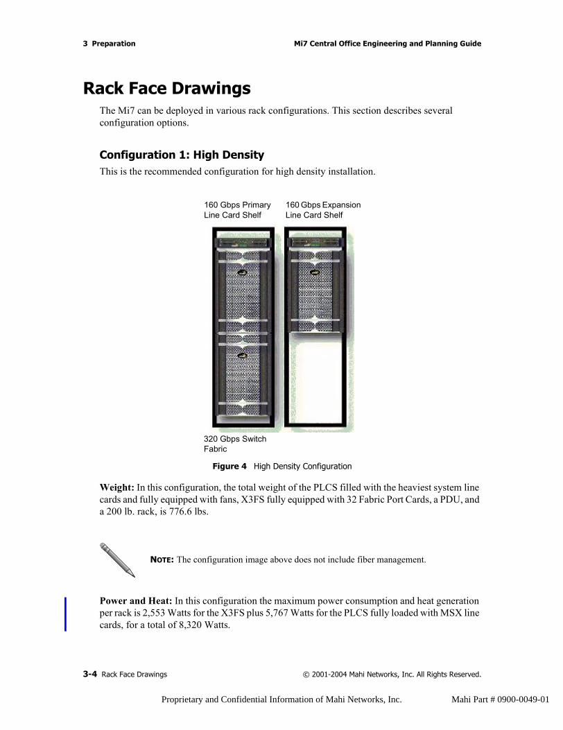
Configuration 1: High DensityThis is the recommended configuration for high density installation.
Figure 4 High Density Configuration
Weight: In this configuration, the total weight of the PLCS filled with the heaviest system line cards and fully equipped with fans, X3FS fully equipped with 32 Fabric Port Cards, a PDU, and a 200 lb. rack, is 776.6 lbs.
Power and Heat: In this configuration the maximum power consumption and heat generation per rack is 2,553 Watts for the X3FS plus 5,767 Watts for the PLCS fully loaded with MSX line cards, for a total of 8,320 Watts.
NOTE: The configuration image above does not include fiber management.
160 Gbps Primary Line Card Shelf
160 Gbps Expansion Line Card Shelf
320 Gbps Switch Fabric
3-4 Rack Face Drawings © 2001-2004 Mahi Networks, Inc. All Rights Reserved.
Proprietary and Confidential Information of Mahi Networks, Inc. Mahi Part # 0900-0049-01
Mi7 Central Office Engineering and Planning Guide 3 Preparation
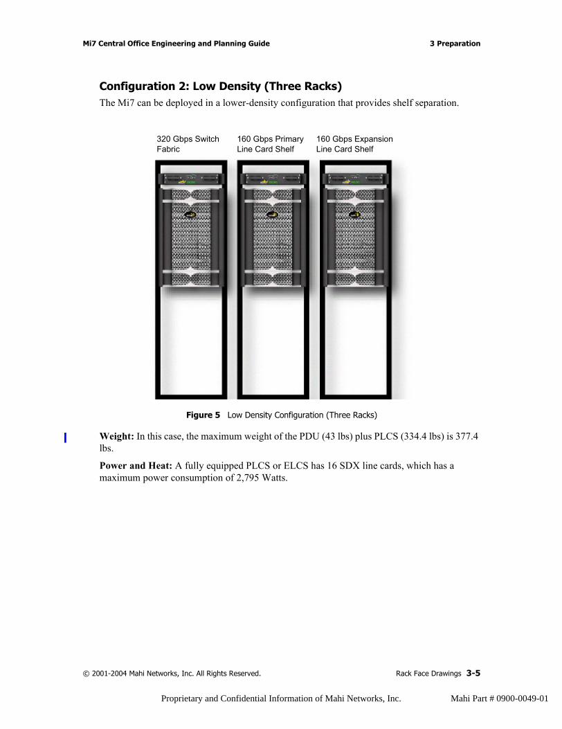
Configuration 2: Low Density (Three Racks)The Mi7 can be deployed in a lower-density configuration that provides shelf separation.
Figure 5 Low Density Configuration (Three Racks)
Weight: In this case, the maximum weight of the PDU (43 lbs) plus PLCS (334.4 lbs) is 377.4 lbs.
Power and Heat: A fully equipped PLCS or ELCS has 16 SDX line cards, which has a maximum power consumption of 2,795 Watts.
320 Gbps Switch Fabric
160 Gbps Primary Line Card Shelf
160 Gbps Expansion Line Card Shelf
© 2001-2004 Mahi Networks, Inc. All Rights Reserved. Rack Face Drawings 3-5
Proprietary and Confidential Information of Mahi Networks, Inc. Mahi Part # 0900-0049-01
3 Preparation Mi7 Central Office Engineering and Planning Guide
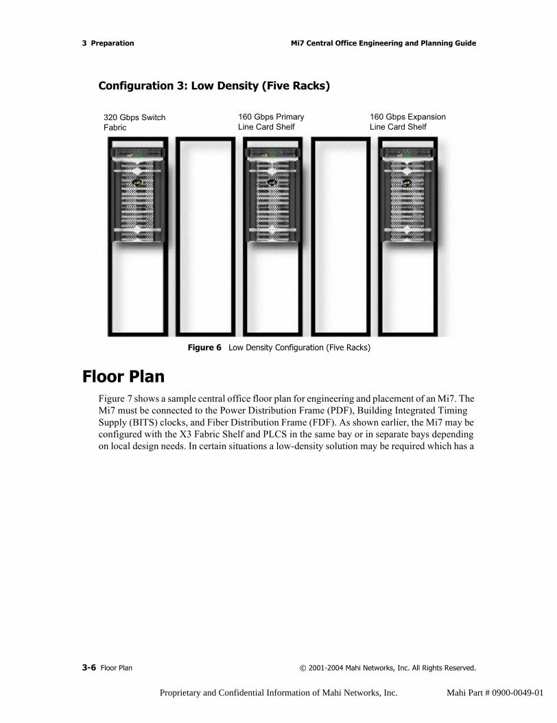
Configuration 3: Low Density (Five Racks)
Figure 6 Low Density Configuration (Five Racks)
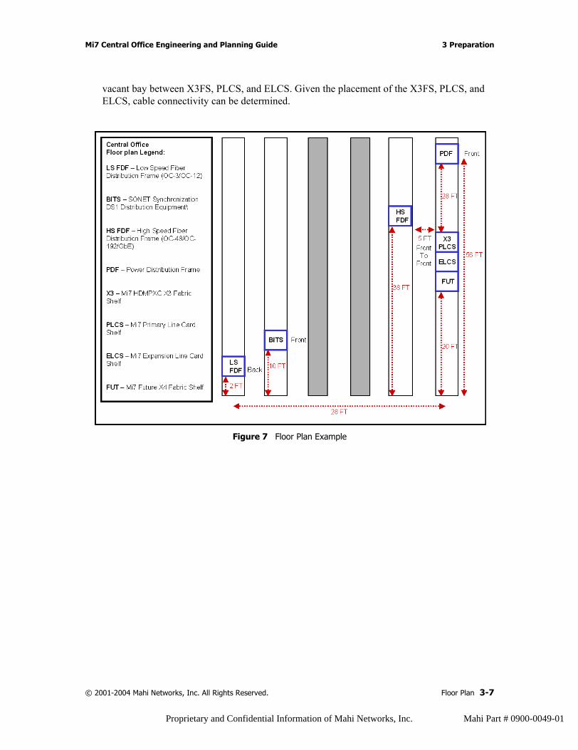
Floor PlanFigure 7 shows a sample central office floor plan for engineering and placement of an Mi7. The Mi7 must be connected to the Power Distribution Frame (PDF), Building Integrated Timing Supply (BITS) clocks, and Fiber Distribution Frame (FDF). As shown earlier, the Mi7 may be configured with the X3 Fabric Shelf and PLCS in the same bay or in separate bays depending on local design needs. In certain situations a low-density solution may be required which has a
320 Gbps Switch Fabric
160 Gbps Primary Line Card Shelf
160 Gbps Expansion Line Card Shelf
3-6 Floor Plan © 2001-2004 Mahi Networks, Inc. All Rights Reserved.
Proprietary and Confidential Information of Mahi Networks, Inc. Mahi Part # 0900-0049-01
Mi7 Central Office Engineering and Planning Guide 3 Preparation
vacant bay between X3FS, PLCS, and ELCS. Given the placement of the X3FS, PLCS, and ELCS, cable connectivity can be determined.
Figure 7 Floor Plan Example
© 2001-2004 Mahi Networks, Inc. All Rights Reserved. Floor Plan 3-7
Proprietary and Confidential Information of Mahi Networks, Inc. Mahi Part # 0900-0049-01
3 Preparation Mi7 Central Office Engineering and Planning Guide
Cables, Wires, and TerminationsThis section provides general information about the cables, wires, and terminations used with the Mi7.
• Power cables from the office facility should be determined by distance and local practices, and should terminate in 3/8-inch diameter two-hole compression lugs, with centers that are one inch apart.
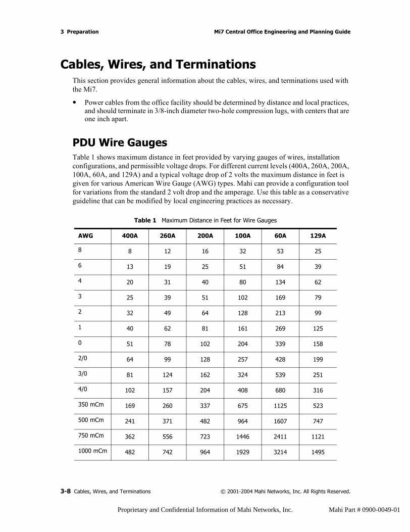
PDU Wire GaugesTable 1 shows maximum distance in feet provided by varying gauges of wires, installation configurations, and permissible voltage drops. For different current levels (400A, 260A, 200A, 100A, 60A, and 129A) and a typical voltage drop of 2 volts the maximum distance in feet is given for various American Wire Gauge (AWG) types. Mahi can provide a configuration tool for variations from the standard 2 volt drop and the amperage. Use this table as a conservative guideline that can be modified by local engineering practices as necessary.
Table 1 Maximum Distance in Feet for Wire Gauges
AWG 400A 260A 200A 100A 60A 129A
8 8 12 16 32 53 25
6 13 19 25 51 84 39
4 20 31 40 80 134 62
3 25 39 51 102 169 79
2 32 49 64 128 213 99
1 40 62 81 161 269 125
0 51 78 102 204 339 158
2/0 64 99 128 257 428 199
3/0 81 124 162 324 539 251
4/0 102 157 204 408 680 316
350 mCm 169 260 337 675 1125 523
500 mCm 241 371 482 964 1607 747
750 mCm 362 556 723 1446 2411 1121
1000 mCm 482 742 964 1929 3214 1495
3-8 Cables, Wires, and Terminations © 2001-2004 Mahi Networks, Inc. All Rights Reserved.
Proprietary and Confidential Information of Mahi Networks, Inc. Mahi Part # 0900-0049-01
Mi7 Central Office Engineering and Planning Guide 3 Preparation
• Timing wire, sense information, and alarm wire must be suitable to transmit a DS-1 signal (for example, a 22-AWG twisted pair, shielded with drain). These wires terminate in wire wrap.
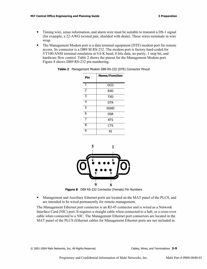
• The Management Modem port is a data terminal equipment (DTE) modem port for remote access. Its connector is a DB9 M RS-232. The modem port is factory hard-coded for VT100/ANSI terminal emulation at 9.6 K baud, 8 bits data, no parity, 1 stop bit, and hardware flow control. Table 2 shows the pinout for the Management Modem port. Figure 8 shows DB9 RS-232 pin numbering.
Figure 8 DB9 RS-232 Connector (Female) Pin Numbers
• Management and Auxiliary Ethernet ports are located on the MAT panel of the PLCS, and are intended to be wired permanently for remote management.
The Management Ethernet port connector is an RJ-45 connector and is wired as a Network Interface Card (NIC) port. It requires a straight cable when connected to a hub, or a cross-over cable when connected to a NIC. The Management Ethernet port connectors are located in the MAT panel of the PLCS (Ethernet cables for Management Ethernet ports are not included in
Table 2 Management Modem DB9 RS-232 (DTE) Connector Pinout
Pin Name/Function
1 DCD
2 RXD
3 TXD
4 DTR
5 SGND
6 DSR
7 RTS
8 CTS
9 RI
9
5
6
1
© 2001-2004 Mahi Networks, Inc. All Rights Reserved. Cables, Wires, and Terminations 3-9
Proprietary and Confidential Information of Mahi Networks, Inc. Mahi Part # 0900-0049-01
3 Preparation Mi7 Central Office Engineering and Planning Guide
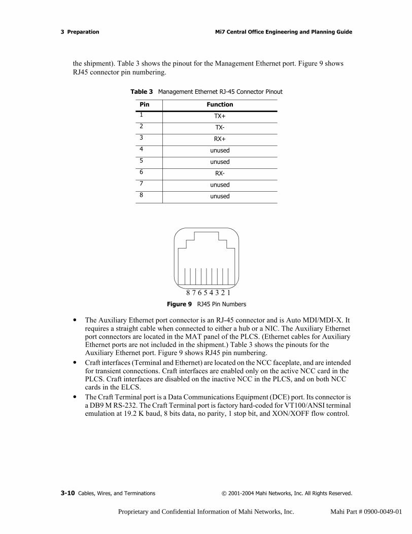
the shipment). Table 3 shows the pinout for the Management Ethernet port. Figure 9 shows RJ45 connector pin numbering.
Figure 9 RJ45 Pin Numbers
• The Auxiliary Ethernet port connector is an RJ-45 connector and is Auto MDI/MDI-X. It requires a straight cable when connected to either a hub or a NIC. The Auxiliary Ethernet port connectors are located in the MAT panel of the PLCS. (Ethernet cables for Auxiliary Ethernet ports are not included in the shipment.) Table 3 shows the pinouts for the Auxiliary Ethernet port. Figure 9 shows RJ45 pin numbering.
• Craft interfaces (Terminal and Ethernet) are located on the NCC faceplate, and are intended for transient connections. Craft interfaces are enabled only on the active NCC card in the PLCS. Craft interfaces are disabled on the inactive NCC in the PLCS, and on both NCC cards in the ELCS.
• The Craft Terminal port is a Data Communications Equipment (DCE) port. Its connector is a DB9 M RS-232. The Craft Terminal port is factory hard-coded for VT100/ANSI terminal emulation at 19.2 K baud, 8 bits data, no parity, 1 stop bit, and XON/XOFF flow control.
Table 3 Management Ethernet RJ-45 Connector Pinout
Pin Function
1 TX+
2 TX-
3 RX+
4 unused
5 unused
6 RX-
7 unused
8 unused
8 7 6 5 4 3 2 1
3-10 Cables, Wires, and Terminations © 2001-2004 Mahi Networks, Inc. All Rights Reserved.
Proprietary and Confidential Information of Mahi Networks, Inc. Mahi Part # 0900-0049-01
Mi7 Central Office Engineering and Planning Guide 3 Preparation
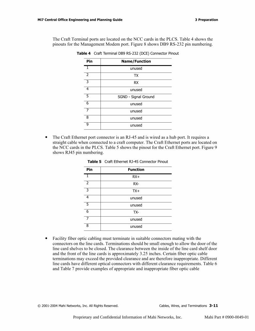
The Craft Terminal ports are located on the NCC cards in the PLCS. Table 4 shows the pinouts for the Management Modem port. Figure 8 shows DB9 RS-232 pin numbering.
• The Craft Ethernet port connector is an RJ-45 and is wired as a hub port. It requires a straight cable when connected to a craft computer. The Craft Ethernet ports are located on the NCC cards in the PLCS. Table 5 shows the pinout for the Craft Ethernet port. Figure 9 shows RJ45 pin numbering.
• Facility fiber optic cabling must terminate in suitable connectors mating with the connectors on the line cards. Terminations should be small enough to allow the door of the line card shelves to be closed. The clearance between the inside of the line card shelf door and the front of the line cards is approximately 3.25 inches. Certain fiber optic cable terminations may exceed the provided clearance and are therefore inappropriate. Different line cards have different optical connectors with different clearance requirements. Table 6 and Table 7 provide examples of appropriate and inappropriate fiber optic cable
Table 4 Craft Terminal DB9 RS-232 (DCE) Connector Pinout
Pin Name/Function
1 unused
2 TX
3 RX
4 unused
5 SGND - Signal Ground
6 unused
7 unused
8 unused
9 unused
Table 5 Craft Ethernet RJ-45 Connector Pinout
Pin Function
1 RX+
2 RX-
3 TX+
4 unused
5 unused
6 TX-
7 unused
8 unused
© 2001-2004 Mahi Networks, Inc. All Rights Reserved. Cables, Wires, and Terminations 3-11
Proprietary and Confidential Information of Mahi Networks, Inc. Mahi Part # 0900-0049-01
3 Preparation Mi7 Central Office Engineering and Planning Guide
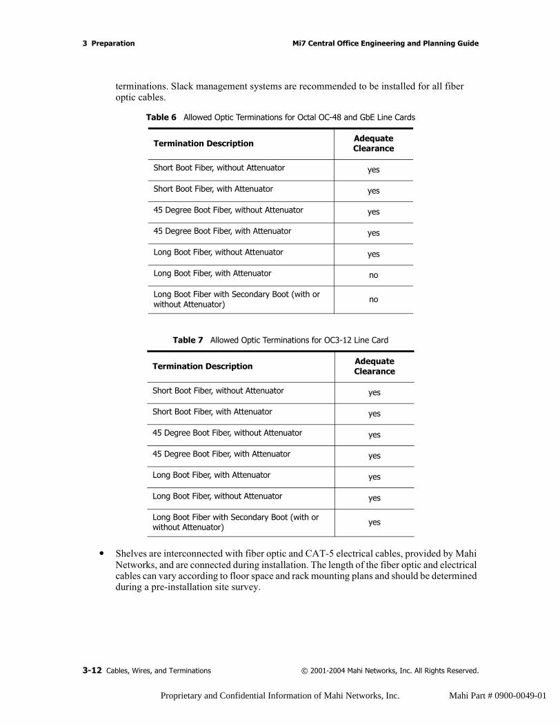
terminations. Slack management systems are recommended to be installed for all fiber optic cables.
• Shelves are interconnected with fiber optic and CAT-5 electrical cables, provided by Mahi Networks, and are connected during installation. The length of the fiber optic and electrical cables can vary according to floor space and rack mounting plans and should be determined during a pre-installation site survey.
Table 6 Allowed Optic Terminations for Octal OC-48 and GbE Line Cards
Termination Description AdequateClearance
Short Boot Fiber, without Attenuator yes
Short Boot Fiber, with Attenuator yes
45 Degree Boot Fiber, without Attenuator yes
45 Degree Boot Fiber, with Attenuator yes
Long Boot Fiber, without Attenuator yes
Long Boot Fiber, with Attenuator no
Long Boot Fiber with Secondary Boot (with or without Attenuator) no
Table 7 Allowed Optic Terminations for OC3-12 Line Card
Termination Description AdequateClearance
Short Boot Fiber, without Attenuator yes
Short Boot Fiber, with Attenuator yes
45 Degree Boot Fiber, without Attenuator yes
45 Degree Boot Fiber, with Attenuator yes
Long Boot Fiber, with Attenuator yes
Long Boot Fiber, without Attenuator yes
Long Boot Fiber with Secondary Boot (with or without Attenuator) yes
3-12 Cables, Wires, and Terminations © 2001-2004 Mahi Networks, Inc. All Rights Reserved.
Proprietary and Confidential Information of Mahi Networks, Inc. Mahi Part # 0900-0049-01
Mi7 Central Office Engineering and Planning Guide 3 Preparation
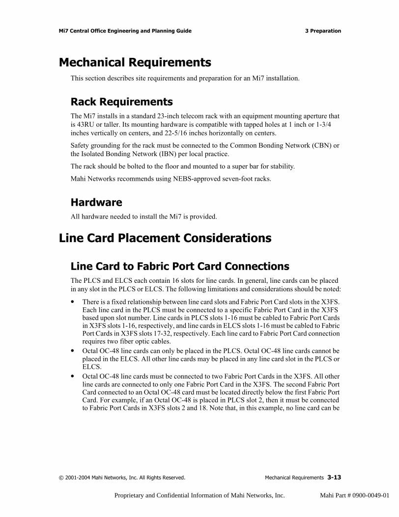
Mechanical RequirementsThis section describes site requirements and preparation for an Mi7 installation.
Rack RequirementsThe Mi7 installs in a standard 23-inch telecom rack with an equipment mounting aperture that is 43RU or taller. Its mounting hardware is compatible with tapped holes at 1 inch or 1-3/4 inches vertically on centers, and 22-5/16 inches horizontally on centers.
Safety grounding for the rack must be connected to the Common Bonding Network (CBN) or the Isolated Bonding Network (IBN) per local practice.
The rack should be bolted to the floor and mounted to a super bar for stability.
Mahi Networks recommends using NEBS-approved seven-foot racks.
HardwareAll hardware needed to install the Mi7 is provided.
Line Card Placement Considerations
Line Card to Fabric Port Card ConnectionsThe PLCS and ELCS each contain 16 slots for line cards. In general, line cards can be placed in any slot in the PLCS or ELCS. The following limitations and considerations should be noted:
• There is a fixed relationship between line card slots and Fabric Port Card slots in the X3FS. Each line card in the PLCS must be connected to a specific Fabric Port Card in the X3FS based upon slot number. Line cards in PLCS slots 1-16 must be cabled to Fabric Port Cards in X3FS slots 1-16, respectively, and line cards in ELCS slots 1-16 must be cabled to Fabric Port Cards in X3FS slots 17-32, respectively. Each line card to Fabric Port Card connection requires two fiber optic cables.
• Octal OC-48 line cards can only be placed in the PLCS. Octal OC-48 line cards cannot be placed in the ELCS. All other line cards may be placed in any line card slot in the PLCS or ELCS.
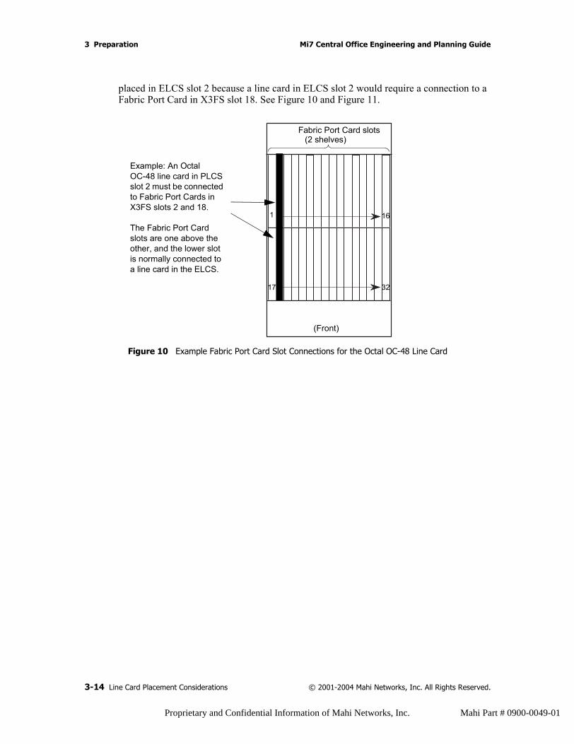
• Octal OC-48 line cards must be connected to two Fabric Port Cards in the X3FS. All other line cards are connected to only one Fabric Port Card in the X3FS. The second Fabric Port Card connected to an Octal OC-48 card must be located directly below the first Fabric Port Card. For example, if an Octal OC-48 is placed in PLCS slot 2, then it must be connected to Fabric Port Cards in X3FS slots 2 and 18. Note that, in this example, no line card can be
© 2001-2004 Mahi Networks, Inc. All Rights Reserved. Mechanical Requirements 3-13
Proprietary and Confidential Information of Mahi Networks, Inc. Mahi Part # 0900-0049-01
3 Preparation Mi7 Central Office Engineering and Planning Guide
placed in ELCS slot 2 because a line card in ELCS slot 2 would require a connection to a Fabric Port Card in X3FS slot 18. See Figure 10 and Figure 11.
Figure 10 Example Fabric Port Card Slot Connections for the Octal OC-48 Line Card
(Front)
Fabric Port Card slots (2 shelves)
1 16
17 32
Example: An Octal OC-48 line card in PLCS slot 2 must be connected to Fabric Port Cards in X3FS slots 2 and 18.
The Fabric Port Card slots are one above the other, and the lower slot is normally connected to a line card in the ELCS.
3-14 Line Card Placement Considerations © 2001-2004 Mahi Networks, Inc. All Rights Reserved.
Proprietary and Confidential Information of Mahi Networks, Inc. Mahi Part # 0900-0049-01
Mi7 Central Office Engineering and Planning Guide 3 Preparation
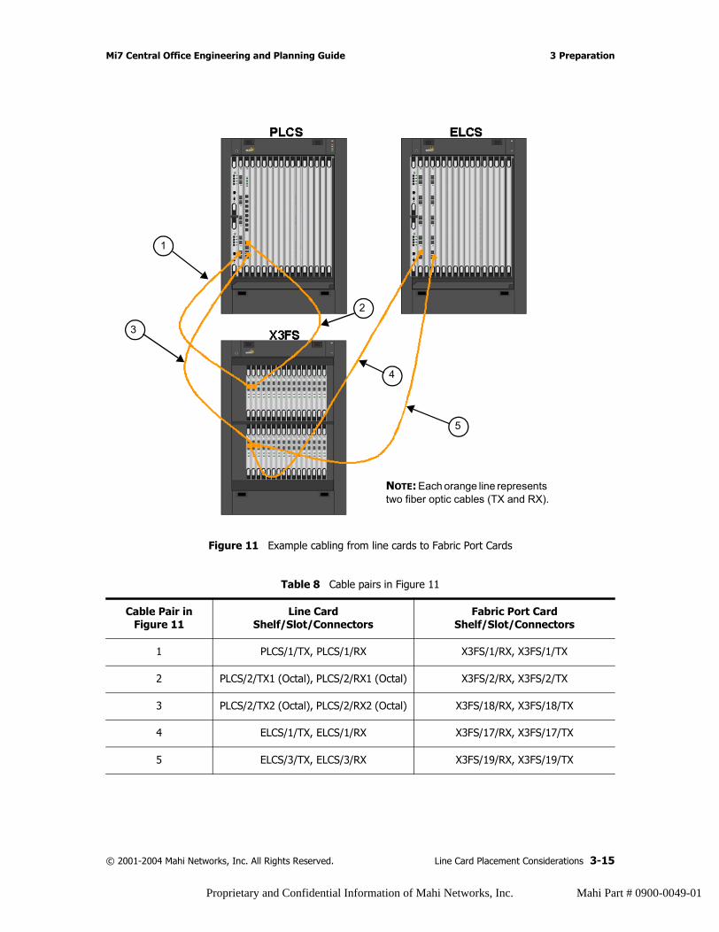
Figure 11 Example cabling from line cards to Fabric Port Cards
Table 8 Cable pairs in Figure 11
Cable Pair in Figure 11
Line CardShelf/Slot/Connectors
Fabric Port CardShelf/Slot/Connectors
1 PLCS/1/TX, PLCS/1/RX X3FS/1/RX, X3FS/1/TX
2 PLCS/2/TX1 (Octal), PLCS/2/RX1 (Octal) X3FS/2/RX, X3FS/2/TX
3 PLCS/2/TX2 (Octal), PLCS/2/RX2 (Octal) X3FS/18/RX, X3FS/18/TX
4 ELCS/1/TX, ELCS/1/RX X3FS/17/RX, X3FS/17/TX
5 ELCS/3/TX, ELCS/3/RX X3FS/19/RX, X3FS/19/TX
NOTE: Each orange line represents two fiber optic cables (TX and RX).
1
2
3
4
5
© 2001-2004 Mahi Networks, Inc. All Rights Reserved. Line Card Placement Considerations 3-15
Proprietary and Confidential Information of Mahi Networks, Inc. Mahi Part # 0900-0049-01

3 Preparation Mi7 Central Office Engineering and Planning Guide
Slot Assignment Scheme with Octal OC-48 Line CardsSpecial consideration should be given to assigning line card slots in deployments that include both Octal 48 line cards and an ELCS. Octal OC-48 line cards have two special requirements: they can only be assigned to PLCS slots, and they require that the corresponding slot in the ELCS remain blank. These special requirements can cause certain assignment schemes to result in stranded (unusable) line card capacity in the Mi7.
The suggested assignment scheme is to alternate between the PLCS and ELCS when assigning line card slots. The line card slots are ordered as: PLCS slot 1, ELCS slot 1, PLCS slot 2, ELCS slot 2, and so on. Because Octal OC-48 line cards can only be placed in the PLCS, this assignment scheme may at times lead to “skipped” slots in the ELCS (an ELCS slot must be skipped if it is next in line for assignment but the card to be assigned is an Octal 48). Any skipped slots should be backfilled as new non-Octal OC-48 line cards are assigned.
Other slot assignment schemes may result in stranded capacity or the inability to install an Octal OC-48. For example, a scheme that assigns all PLCS slots prior to assignment any ELCS slots results in no suitable slots for Octal OC-48 line cards after the placement of only 16 cards.
Special RequirementsThis section describes requirements for building, environmental, electrical, timing, and space considerations.
Building RequirementsThe building housing the Mi7 installation should have a loading dock for equipment delivery, and a hand truck or forklift for moving equipment to the installation location. The building should have an elevator if the installation site is on a floor other than ground level.
Shipping PalletsThe Mi7 shelves are shipped on wooden pallets that measure about 31 inches wide, 33 inches deep, and 48 inches high. The loaded weight of the pallets is about 175 lbs (about 80 kg). All doors and elevators to the installation location must be able to accommodate the pallet size.
Cable ManagementFiber raceways, fiber trays, or cable ladder racks are recommended for cable management.
Spares StorageSpare cards for the Mi7 require special storage consideration. For dimensions of individual cards, see Appendix A, “Mi7 Specifications.”
3-16 Special Requirements © 2001-2004 Mahi Networks, Inc. All Rights Reserved.
Proprietary and Confidential Information of Mahi Networks, Inc. Mahi Part # 0900-0049-01

Mi7 Central Office Engineering and Planning Guide 3 Preparation
Environmental RequirementsThe Mi7 requires an operating environment between 32° and 122° F, from -200 to 13,123 Ft. (4000 meters), 10% to 85% humidity (non-condensing), and adequate cooling to accommodate a 10,000 Watt fully configured system.
Electrical RequirementsThe Mi7 typically requires two power inputs per shelf of -48 VDC (-38 VDC to -75 VDC), which are designated A and B input facilities. In certain cases, a single pair of A and B input facilities can power two shelves located in a single rack. Each input facility must consist of two -48V cables, and two return cables. Each rack in the Mi7 installation must be separately powered.
The input facilities must be rated to supply 80 Amp or 150 Amp depending on the requirements of the specific shelves in the rack. Each PDU supplied with the Mi7 is equipped with the appropriate circuit breakers.
Timing RequirementsThe recommended timing source for the Mi7 is Building Integrated Timing Supply (BITS) or Synchronization Timing Unit (STU) (both supplied by copper wire). You can also configure the system to operate using line timing.
Space RequirementsThe Mi7 installation fits into a standard seven-foot rack. The front cover has a swing radius of 20 inches. A line card installation requires about 20 inches in front of the shelf in order to line up the line card properly with the slot.
© 2001-2004 Mahi Networks, Inc. All Rights Reserved. Special Requirements 3-17
Proprietary and Confidential Information of Mahi Networks, Inc. Mahi Part # 0900-0049-01
3 Preparation Mi7 Central Office Engineering and Planning Guide
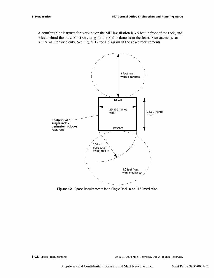
A comfortable clearance for working on the Mi7 installation is 3.5 feet in front of the rack, and 3 feet behind the rack. Most servicing for the Mi7 is done from the front. Rear access is for X3FS maintenance only. See Figure 12 for a diagram of the space requirements.
Figure 12 Space Requirements for a Single Rack in an Mi7 Installation
3 feet rearwork clearance
FRONT
REAR
25.875 inches23.62 inchesdeep
wide
20-inchfront coverswing radius
Footprint of a single rack -
3.5 feet frontwork clearance
perimeter includesrack rails
3-18 Special Requirements © 2001-2004 Mahi Networks, Inc. All Rights Reserved.
Proprietary and Confidential Information of Mahi Networks, Inc. Mahi Part # 0900-0049-01
Mi7 Central Office Engineering and Planning Guide 3 Preparation
Rack Mounting OptionsThe Mi7 PLCS, ELCS, and X3FS shelves can be mounted in a rack in either a front mount or mid mount configuration. The Mi7 PDU can be mounted only in a front mount configuration.
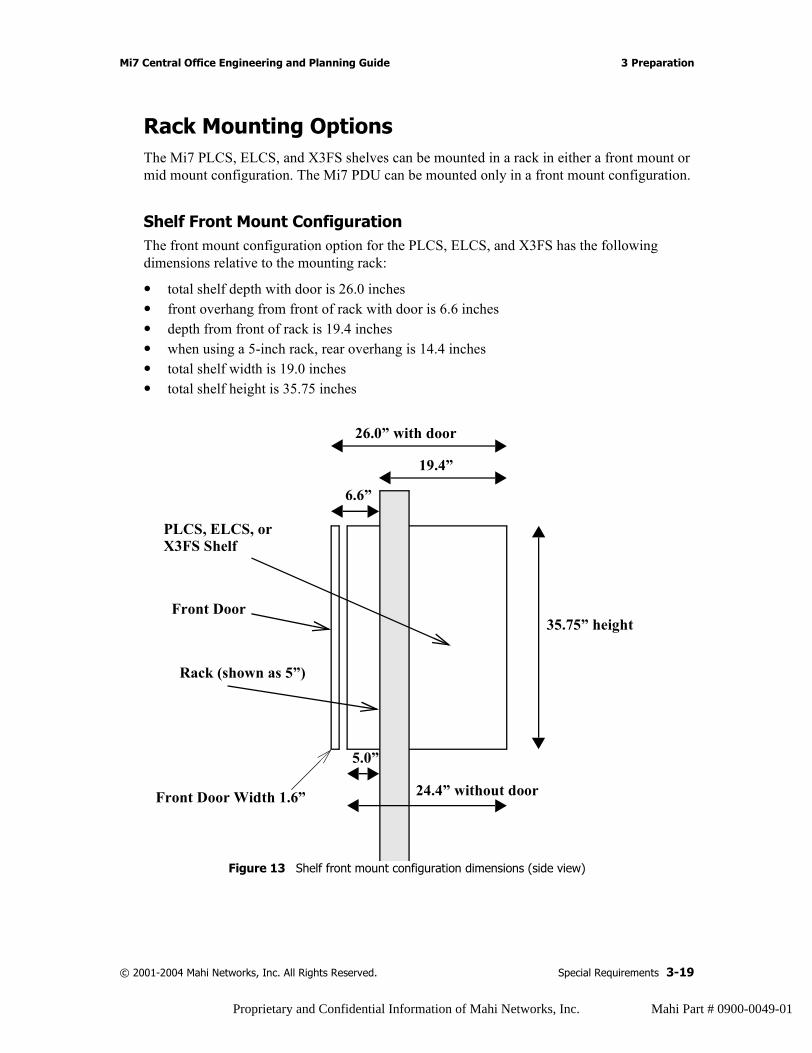
Shelf Front Mount ConfigurationThe front mount configuration option for the PLCS, ELCS, and X3FS has the following dimensions relative to the mounting rack:
• total shelf depth with door is 26.0 inches• front overhang from front of rack with door is 6.6 inches• depth from front of rack is 19.4 inches• when using a 5-inch rack, rear overhang is 14.4 inches• total shelf width is 19.0 inches• total shelf height is 35.75 inches
Figure 13 Shelf front mount configuration dimensions (side view)
26.0” with door
35.75” height
5.0”
19.4”
6.6”
PLCS, ELCS, orX3FS Shelf
Front Door
Rack (shown as 5”)
24.4” without doorFront Door Width 1.6”
© 2001-2004 Mahi Networks, Inc. All Rights Reserved. Special Requirements 3-19
Proprietary and Confidential Information of Mahi Networks, Inc. Mahi Part # 0900-0049-01
3 Preparation Mi7 Central Office Engineering and Planning Guide
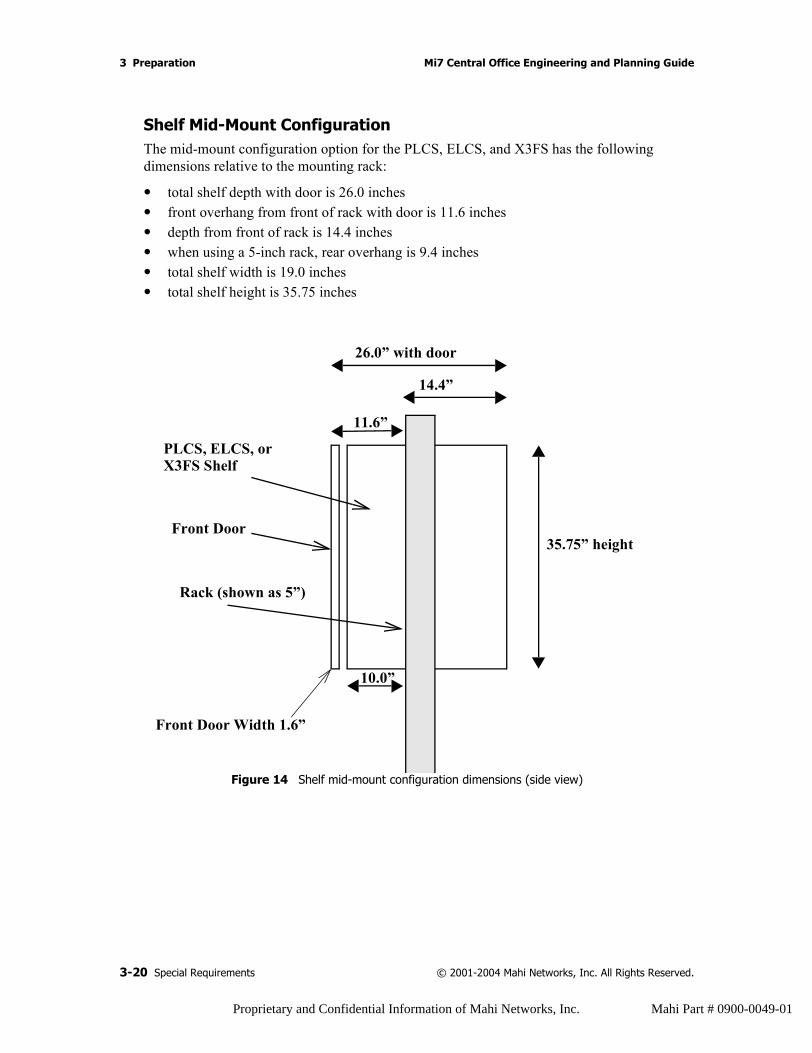
Shelf Mid-Mount ConfigurationThe mid-mount configuration option for the PLCS, ELCS, and X3FS has the following dimensions relative to the mounting rack:
• total shelf depth with door is 26.0 inches• front overhang from front of rack with door is 11.6 inches • depth from front of rack is 14.4 inches• when using a 5-inch rack, rear overhang is 9.4 inches• total shelf width is 19.0 inches• total shelf height is 35.75 inches
Figure 14 Shelf mid-mount configuration dimensions (side view)
26.0” with door
35.75” height
10.0”
14.4”
11.6”
PLCS, ELCS, orX3FS Shelf
Front Door
Rack (shown as 5”)
Front Door Width 1.6”
3-20 Special Requirements © 2001-2004 Mahi Networks, Inc. All Rights Reserved.
Proprietary and Confidential Information of Mahi Networks, Inc. Mahi Part # 0900-0049-01
Mi7 Central Office Engineering and Planning Guide 3 Preparation
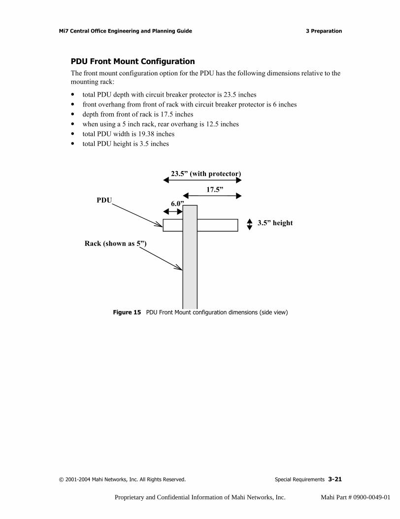
PDU Front Mount ConfigurationThe front mount configuration option for the PDU has the following dimensions relative to the mounting rack:
• total PDU depth with circuit breaker protector is 23.5 inches• front overhang from front of rack with circuit breaker protector is 6 inches • depth from front of rack is 17.5 inches• when using a 5 inch rack, rear overhang is 12.5 inches• total PDU width is 19.38 inches• total PDU height is 3.5 inches
Figure 15 PDU Front Mount configuration dimensions (side view)
23.5” (with protector)
3.5” height
6.0”
17.5”
Rack (shown as 5”)
PDU
© 2001-2004 Mahi Networks, Inc. All Rights Reserved. Special Requirements 3-21
Proprietary and Confidential Information of Mahi Networks, Inc. Mahi Part # 0900-0049-01
3 Preparation Mi7 Central Office Engineering and Planning Guide
Handling Requirements
Inserting Cards
To insert a line card into a Mahi Networks Mi7 shelf:
1. Locate slot that card will be installed in.
2. Slide card into slot slowly, ensuring that backside of card is not damaged by neighboring card.
3. After ejector handle claws engage with mating channel in chassis, press with even force on both top and bottom ejector handles.
ELECTROSTATIC DISCHARGE: To avoid damage to cards from electrostatic discharge, be sure to follow appropriate grounding procedures as described in “Dissipating Static Electricity” on page 2-5.
CAUTION: Improper use of ejectors can cause breakage.
3-22 Special Requirements © 2001-2004 Mahi Networks, Inc. All Rights Reserved.
Proprietary and Confidential Information of Mahi Networks, Inc. Mahi Part # 0900-0049-01
Mi7 Central Office Engineering and Planning Guide 3 Preparation
Extracting Cards
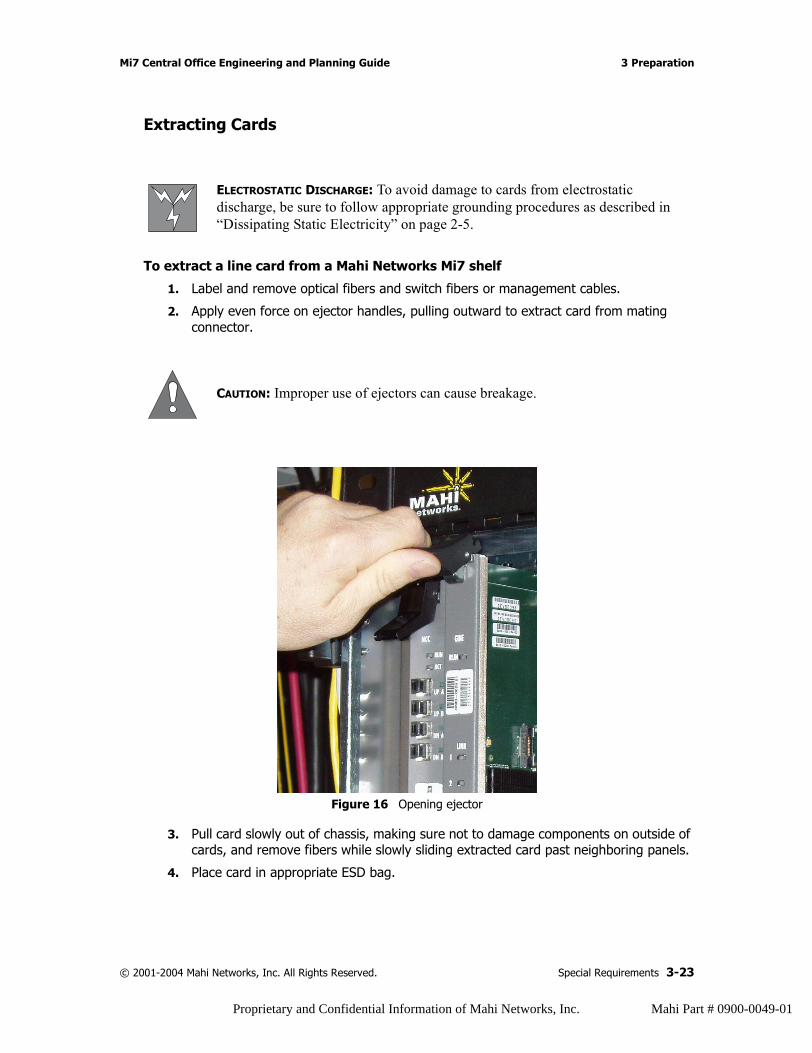
To extract a line card from a Mahi Networks Mi7 shelf
1. Label and remove optical fibers and switch fibers or management cables.
2. Apply even force on ejector handles, pulling outward to extract card from mating connector.
Figure 16 Opening ejector
3. Pull card slowly out of chassis, making sure not to damage components on outside of cards, and remove fibers while slowly sliding extracted card past neighboring panels.
4. Place card in appropriate ESD bag.
ELECTROSTATIC DISCHARGE: To avoid damage to cards from electrostatic discharge, be sure to follow appropriate grounding procedures as described in “Dissipating Static Electricity” on page 2-5.
CAUTION: Improper use of ejectors can cause breakage.
© 2001-2004 Mahi Networks, Inc. All Rights Reserved. Special Requirements 3-23
Proprietary and Confidential Information of Mahi Networks, Inc. Mahi Part # 0900-0049-01

3 Preparation Mi7 Central Office Engineering and Planning Guide
Tools and EquipmentThe following tools and equipment are required in order to complete the installation of the Mi7:
• Safety glasses• Wire wrap tool• Wire cutters and crimpers• Flat blade screwdriver, 1/4-inch head• Flat blade screwdriver, 1/8-inch head• Phillips screwdriver• 3/8-inch nut driver• 1/2-inch nut driver• 5/8-inch hex nut socket• 1/2-inch hex nut socket• Torque wrench• Optical meter• Fiber-cleaning box• Tie wraps or lacing string• Carpenter’s level, minimum 2 feet long• Central Office approved tape measure• Crimping tools (see details below)• Stepping stool or small ladder• Craft computer (laptop)• SONET test set• OmniBER• 850nm optical source laser• Optical Power Meter (800–1550nm)
Crimping ToolsThe following Thomas and Betts tools for crimping wire lugs are recommended for the application of standardized color coded copper compression lugs from a variety of manufacturers. The following list is not comprehensive, but is intended to provide examples of possible tools. Mahi Networks, Inc. does not certify these tools for any application and cannot guarantee their applicability. Please consult the manufacturer to assure that the specific application needs will be met by any choice of tools and lugs.
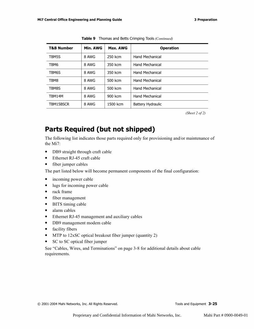
Table 9 Thomas and Betts Crimping Tools
T&B Number Min. AWG Max. AWG Operation
TBM5 8 AWG 250 kcm Hand Mechanical
(Sheet 1 of 2)
3-24 Tools and Equipment © 2001-2004 Mahi Networks, Inc. All Rights Reserved.
Proprietary and Confidential Information of Mahi Networks, Inc. Mahi Part # 0900-0049-01
Mi7 Central Office Engineering and Planning Guide 3 Preparation
Parts Required (but not shipped)The following list indicates those parts required only for provisioning and/or maintenance of the Mi7:
• DB9 straight through craft cable• Ethernet RJ-45 craft cable• fiber jumper cablesThe part listed below will become permanent components of the final configuration:
• incoming power cable• lugs for incoming power cable• rack frame• fiber management• BITS timing cable• alarm cables• Ethernet RJ-45 management and auxiliary cables• DB9 management modem cable• facility fibers• MTP to 12xSC optical breakout fiber jumper (quantity 2)• SC to SC optical fiber jumperSee “Cables, Wires, and Terminations” on page 3-8 for additional details about cable requirements.
TBM5S 8 AWG 250 kcm Hand Mechanical
TBM6 8 AWG 350 kcm Hand Mechanical
TBM6S 8 AWG 350 kcm Hand Mechanical
TBM8 8 AWG 500 kcm Hand Mechanical
TBM8S 8 AWG 500 kcm Hand Mechanical
TBM14M 8 AWG 900 kcm Hand Mechanical
TBM15BSCR 8 AWG 1500 kcm Battery Hydraulic
Table 9 Thomas and Betts Crimping Tools (Continued)
T&B Number Min. AWG Max. AWG Operation
(Sheet 2 of 2)
© 2001-2004 Mahi Networks, Inc. All Rights Reserved. Tools and Equipment 3-25
Proprietary and Confidential Information of Mahi Networks, Inc. Mahi Part # 0900-0049-01
3 Preparation Mi7 Central Office Engineering and Planning Guide
Preparation and Installation
Site PreparationCompare the invoice to the office documents and confirm that all the necessary equipment has been received.
Before installing the Mi7 system, the following items must be ready:
• Rack installed per local practice• Power feed and cabling to the Mi7
Installation Approach
NOTE: Mi7 hardware components are installed from the bottom up. This means that all bottom components are mounted in the rack before the top components. This is both by design and to minimize safety concerns.
3-26 Preparation and Installation © 2001-2004 Mahi Networks, Inc. All Rights Reserved.
Proprietary and Confidential Information of Mahi Networks, Inc. Mahi Part # 0900-0049-01

Mi7 Central Office Engineering and Planning Guide 3 Preparation
Mechanical DescriptionsThis section contains a description of each of the mechanical units of the Mi7. See Figure 17 for drawings of the main rack units.
Figure 17 The Main Rack Units in the Mi7 Installation
..........
......
.........
......
..........
......
.........
......
..........
......
..........
......
.........
......
..........
......
.........
......
..........
......
..........
......
.........
......
..........
......
.........
......
..........
......
Rack
Shelf Door
Power Distribution Unit (PDU)
Primary Line Card Shelf (PLCS)
X3 Fabric Shelf (X3FS)
Expansion Line Card Shelf (ELCS)
© 2001-2004 Mahi Networks, Inc. All Rights Reserved. Mechanical Descriptions 3-27
Proprietary and Confidential Information of Mahi Networks, Inc. Mahi Part # 0900-0049-01
3 Preparation Mi7 Central Office Engineering and Planning Guide
RacksThe rack mounting size is 2” WECO or 1/75” EIA. The Mi7 installs in 23-inch or ETSI racks. It is recommended that seismic racks are used.
ShelvesThere are, at minimum, two shelves in an Mi7 installation: an X3FS and a PLCS. Each shelf measures 19 inches wide, 24-1/2 inches deep, and 35-3/4 inches high. The door adds about 1-1/2 inches to the depth.
The installation can be expanded by adding an ELCS, which is the same in size as the X3FS and PLCS.
The weight of each shelf, without fans, cables, and cards installed, is about 110 lbs (50 kg). Each shelf ships with the mounting brackets attached.
X3 Fabric ShelfThe X3FS houses Fabric Port Cards, XC switch matrix cards, and fabric controller cards.
Primary Line Card ShelfThe PLCS houses network controller cards and line cards.
Expansion Line Card ShelfThe ELCS houses network controller cards and line cards.
Power Distribution UnitThe PDU is 19.25 inches wide, 24 inches deep (including terminal connectors extend 6.50 inches from the back of the rack), and 3.50 inches high. The terminal connectors have an attached plastic safety cover. The PDU ships with part of the mounting system attached. The rest of the mounting system is attached during installation on the rack.
3-28 Mechanical Descriptions © 2001-2004 Mahi Networks, Inc. All Rights Reserved.
Proprietary and Confidential Information of Mahi Networks, Inc. Mahi Part # 0900-0049-01

4 Configurations
What’s Inside?“Circuit Breaker Configurations” on page 4-2
“Shelf Cabling Schedule” on page 4-3
“Office Facility Power Recommendations” on page 4-4
“Wire and Cable Routing” on page 4-5
“MAT Layouts” on page 4-5
“The Important Role of Card Blanks” on page 4-7
© 2001-2004 Mahi Networks, Inc. All Rights Reserved. 4-1
Proprietary and Confidential Information of Mahi Networks, Inc. Mahi Part # 0900-0049-01
4 Configurations Mi7 Central Office Engineering and Planning Guide
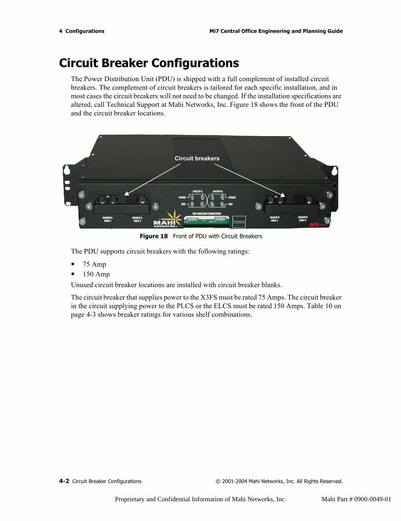
Circuit Breaker ConfigurationsThe Power Distribution Unit (PDU) is shipped with a full complement of installed circuit breakers. The complement of circuit breakers is tailored for each specific installation, and in most cases the circuit breakers will not need to be changed. If the installation specifications are altered, call Technical Support at Mahi Networks, Inc. Figure 18 shows the front of the PDU and the circuit breaker locations.
Figure 18 Front of PDU with Circuit Breakers
The PDU supports circuit breakers with the following ratings:
• 75 Amp• 150 AmpUnused circuit breaker locations are installed with circuit breaker blanks.
The circuit breaker that supplies power to the X3FS must be rated 75 Amps. The circuit breaker in the circuit supplying power to the PLCS or the ELCS must be rated 150 Amps. Table 10 on page 4-3 shows breaker ratings for various shelf combinations.
Circuit breakers
4-2 Circuit Breaker Configurations © 2001-2004 Mahi Networks, Inc. All Rights Reserved.
Proprietary and Confidential Information of Mahi Networks, Inc. Mahi Part # 0900-0049-01
Mi7 Central Office Engineering and Planning Guide 4 Configurations
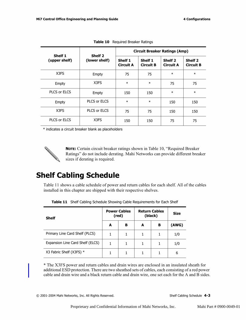
Shelf Cabling ScheduleTable 11 shows a cable schedule of power and return cables for each shelf. All of the cables installed in this chapter are shipped with their respective shelves.
* The X3FS power and return cables and drain wires are enclosed in an insulated sheath for additional ESD protection. There are two sheathed sets of cables, each consisting of a red power cable and drain wire and a black return cable and drain wire, one set each for the A and B sides.
Table 10 Required Breaker Ratings
Shelf 1(upper shelf)
Shelf 2(lower shelf)
Circuit Breaker Ratings (Amp)
Shelf 1Circuit A
Shelf 1Circuit B
Shelf 2Circuit A
Shelf 2Circuit B
X3FS Empty 75 75 * *
Empty X3FS * * 75 75
PLCS or ELCS Empty 150 150 * *
Empty PLCS or ELCS * * 150 150
X3FS PLCS or ELCS 75 75 150 150
PLCS or ELCS X3FS 150 150 75 75
* indicates a circuit breaker blank as placeholders
NOTE: Certain circuit breaker ratings shown in Table 10, “Required Breaker Ratings” do not include derating. Mahi Networks can provide different breaker sizes if derating is required.
Table 11 Shelf Cabling Schedule Showing Cable Requirements for Each Shelf
Shelf
Power Cables(red)
Return Cables(black) Size
A B A B (AWG)
Primary Line Card Shelf (PLCS) 1 1 1 1 1/0
Expansion Line Card Shelf (ELCS) 1 1 1 1 1/0
X3 Fabric Shelf (X3FS) * 1 1 1 1 6
© 2001-2004 Mahi Networks, Inc. All Rights Reserved. Shelf Cabling Schedule 4-3
Proprietary and Confidential Information of Mahi Networks, Inc. Mahi Part # 0900-0049-01
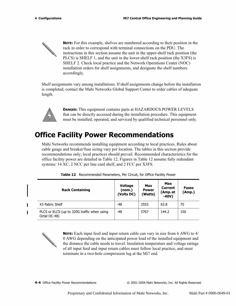
4 Configurations Mi7 Central Office Engineering and Planning Guide
Shelf assignments vary among installations. If shelf assignments change before the installation is completed, contact the Mahi Networks Global Support Center to order cables of adequate length.
Office Facility Power RecommendationsMahi Networks recommends installing equipment according to local practices. Rules about cable gauge and breaker/fuse sizing vary per location. The tables in this section provide recommendations only; local practices should prevail. Recommended characteristics for the office facility power are detailed in Table 12. Figures in Table 12 assume fully redundant systems: 14 XC, 2 NCC per line card shelf, and 2 FCC per X3FS.
NOTE: For this example, shelves are numbered according to their position in the rack in order to correspond with terminal connections on the PDU. The instructions in this section assume the unit in the upper-shelf rack position (the PLCS) is SHELF 1, and the unit in the lower-shelf rack position (the X3FS) is SHELF 2. Check local practice and the Network Operations Center (NOC) installation orders for shelf assignments, and designate the shelf numbers accordingly.
DANGER: This equipment contains parts at HAZARDOUS POWER LEVELS that can be directly accessed during the installation procedure. This equipment must be installed, operated, and serviced by qualified technical personnel only.
Table 12 Recommended Parameters, Per Circuit, for Office Facility Power
Rack ContainingVoltage (nom.)
(Volts DC)
Max Power
(Watts)
Max Current (Amp. at
-40V)
Fuses(Amp.)
X3 Fabric Shelf -48 2553 63.8 75
PLCS or ELCS (up to 320G traffic when using Octal OC-48)
-48 5767 144.2 150
NOTE: Each input feed and input return cable can vary in size from 6 AWG to 4/0 AWG depending on the anticipated power load of the installed equipment and the distance the cable needs to travel. Insulation temperature and voltage ratings of all input feed and input return cables must follow local practice, and must terminate in a two-hole compression lug at the Mi7 end.
4-4 Office Facility Power Recommendations © 2001-2004 Mahi Networks, Inc. All Rights Reserved.
Proprietary and Confidential Information of Mahi Networks, Inc. Mahi Part # 0900-0049-01

Mi7 Central Office Engineering and Planning Guide 4 Configurations
Power to each PDU is typically supplied through four input feed cables and four input return cables. Racks installed with only a single shelf may use only two input feed cables and two input return cables. Racks installed with two shelves may use only two input feed cables and two input return cables.
Wire and Cable RoutingThe X3FS, PLCS, and ELCS each have cable routing ports on the right and left side (see Figure 19). These cable routing ports are the ingress and egress points for all wiring and cabling. Route all wires and cables through the cable routing ports.
Figure 19 Cable Routing Ports
MAT LayoutsThe Maintenance, Alarm, and Timing (MAT) area of each shelf has connections for various external and intershelf wiring. The MAT layout is different for each Mi7 shelf type, as shown in Figure 20 on page 4-6.
..........
......
.........
......
..........
......
.........
......
..........
......
..........
......
.........
......
..........
......
.........
......
..........
......
Cable routing portsX3 Fabric Shelf (X3FS) Primary Line Card Shelf (PLCS) or
Expansion Line Card Shelf (ELCS)
Cable routingports
Cable routingports
© 2001-2004 Mahi Networks, Inc. All Rights Reserved. Wire and Cable Routing 4-5
Proprietary and Confidential Information of Mahi Networks, Inc. Mahi Part # 0900-0049-01
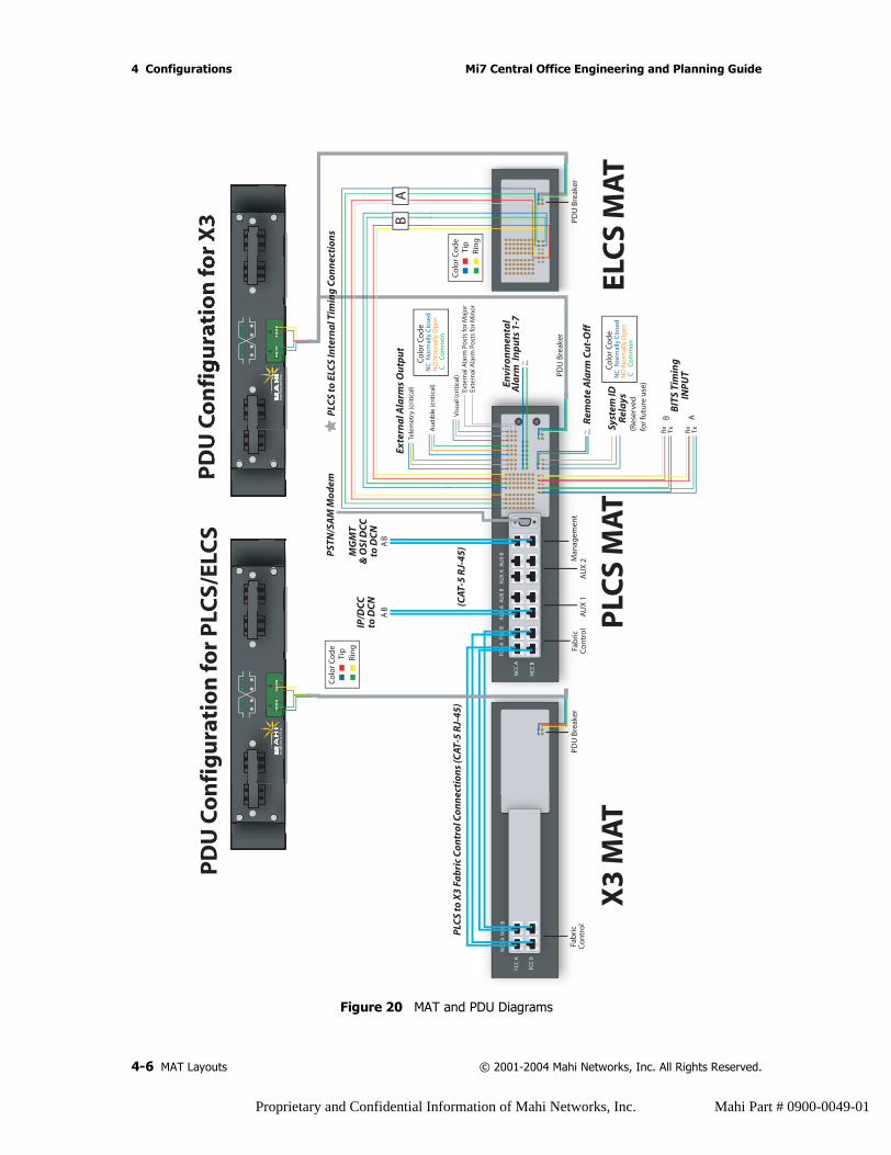
4 Configurations Mi7 Central Office Engineering and Planning Guide
Figure 20 MAT and PDU Diagrams
Fab
ric
Co
ntr
ol
AU
X 1
AU
X 2M
anag
emen
t
PDU
Bre
aker
Exte
rna
l Ala
rms
Ou
tpu
t
PLC
S to
X3
Fab
ric
Co
ntr
ol C
on
nec
tio
ns
(CAT
-5 R
J-45
)
Envi
ron
men
tal
Ala
rm I
np
uts
1-7
Rem
ote
Ala
rm C
ut-
Off
Syst
em ID
Rel
ays
Fab
ric
Co
ntr
ol
FCC
A
FCC
B
NC
C A
FCC
AFC
C B
AU
X A
AU
X B
AU
X A
AU
X B
NC
C A
NC
C B
NC
C B
PDU
Bre
aker
PLC
S M
AT
X3
MA
T
PD
U C
on
fig
ura
tio
n fo
r P
LCS/
ELC
SP
DU
Co
nfi
gu
rati
on
for
X3 PD
U B
reak
er
ELC
S M
AT
A
11
22
B
IP/D
CC
to D
CN
MG
MT
& O
SI D
CC
to D
CN
PST
N/S
AM
Mo
dem
BIT
S Ti
min
gIN
PU
TTxRxTxRx
Rin
g
Tip
Rin
g
Tip
Tele
met
ry (c
riti
cal)
Au
dib
le (c
riti
cal)
Vis
ual
(cri
tica
l)Ex
tern
al A
larm
Po
sts
for M
ajo
rEx
tern
al A
larm
Po
sts
for M
ino
r
NC
No
rmal
ly C
lose
dN
O N
orm
ally
Op
en C
C
om
mo
n
Co
lor C
od
e
NC
No
rmal
ly C
lose
dN
O N
orm
ally
Op
en C
C
om
mo
n
Co
lor C
od
e
AB
AB
AB
Rin
gTi
pC
olo
r Co
de
A B
BA
Rin
gTi
pC
olo
r Co
de
A
11
22
B
(CAT
-5 R
J-45
)
PLC
S to
ELC
S In
tern
al T
imin
g C
on
nec
tio
ns
(Res
erve
d
for f
utu
re u
se)
4-6 MAT Layouts © 2001-2004 Mahi Networks, Inc. All Rights Reserved.
Proprietary and Confidential Information of Mahi Networks, Inc. Mahi Part # 0900-0049-01

Mi7 Central Office Engineering and Planning Guide 4 Configurations
The Important Role of Card BlanksCard blanks are essential to insuring temperature control and electromagnetic management of the Mi7. Every slot of every Mi7 shelf must be populated with either an active card or a card blank. Every type of card has an associated card blank available. A card blank is simply a card of sheet steel with a faceplate, similar in shape to the associated card. All blanks are short enough so that they do not touch the midplane or backplane when fully inserted.
The Mi7 can be populated with varying numbers of cards, depending on the requirements of the installation. Temperature control and electromagnetic management in each of the shelves is dependent on card density, so in a shelf where full population of cards is not required, a complement of blanks must also be installed.
CAUTION: Each slot in the shelf must be populated with either a card or a card blank. Deviation from this scheme may result in equipment damage.
© 2001-2004 Mahi Networks, Inc. All Rights Reserved. The Important Role of Card Blanks 4-7
Proprietary and Confidential Information of Mahi Networks, Inc. Mahi Part # 0900-0049-01

4 Configurations Mi7 Central Office Engineering and Planning Guide
4-8 The Important Role of Card Blanks © 2001-2004 Mahi Networks, Inc. All Rights Reserved.
Proprietary and Confidential Information of Mahi Networks, Inc. Mahi Part # 0900-0049-01
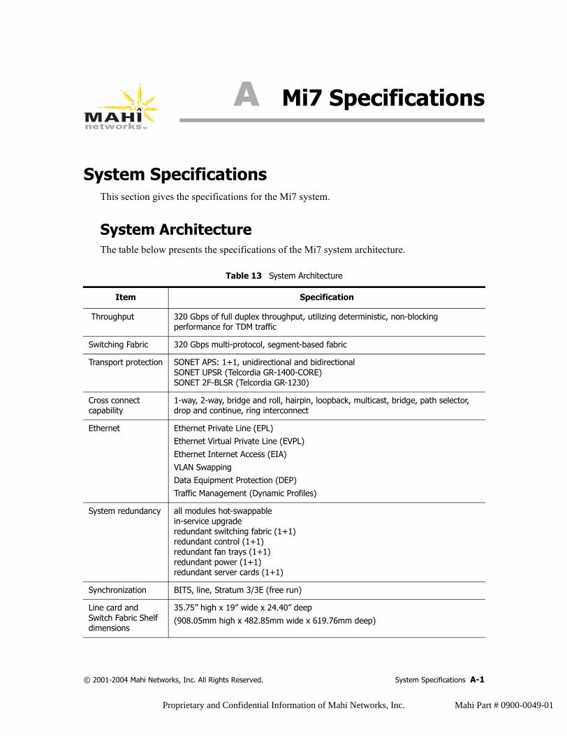
A Mi7 Specifications
System SpecificationsThis section gives the specifications for the Mi7 system.
System ArchitectureThe table below presents the specifications of the Mi7 system architecture.
Table 13 System Architecture
Item Specification
Throughput 320 Gbps of full duplex throughput, utilizing deterministic, non-blocking performance for TDM traffic
Switching Fabric 320 Gbps multi-protocol, segment-based fabric
Transport protection SONET APS: 1+1, unidirectional and bidirectionalSONET UPSR (Telcordia GR-1400-CORE)SONET 2F-BLSR (Telcordia GR-1230)
Cross connect capability
1-way, 2-way, bridge and roll, hairpin, loopback, multicast, bridge, path selector, drop and continue, ring interconnect
Ethernet Ethernet Private Line (EPL)Ethernet Virtual Private Line (EVPL)
Ethernet Internet Access (EIA)
VLAN SwappingData Equipment Protection (DEP)
Traffic Management (Dynamic Profiles)
System redundancy all modules hot-swappablein-service upgraderedundant switching fabric (1+1)redundant control (1+1)redundant fan trays (1+1)redundant power (1+1)redundant server cards (1+1)
Synchronization BITS, line, Stratum 3/3E (free run)
Line card and Switch Fabric Shelf dimensions
35.75” high x 19” wide x 24.40” deep
(908.05mm high x 482.85mm wide x 619.76mm deep)
© 2001-2004 Mahi Networks, Inc. All Rights Reserved. System Specifications A-1
Proprietary and Confidential Information of Mahi Networks, Inc. Mahi Part # 0900-0049-01
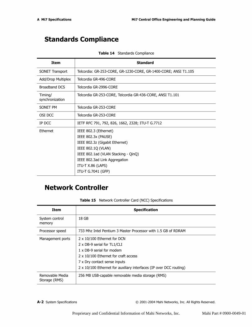
A Mi7 Specifications Mi7 Central Office Engineering and Planning Guide
Standards Compliance
Network Controller
Table 14 Standards Compliance
Item Standard
SONET Transport Telcordia: GR-253-CORE, GR-1230-CORE, GR-1400-CORE; ANSI T1.105
Add/Drop Multiplex Telcordia GR-496-CORE
Broadband DCS Telcordia GR-2996-CORE
Timing/synchronization
Telcordia GR-253-CORE, Telcordia GR-436-CORE, ANSI T1.101
SONET PM Telcordia GR-253-CORE
OSI DCC Telcordia GR-253-CORE
IP DCC IETF RFC 791, 792, 826, 1662, 2328; ITU-T G.7712
Ethernet IEEE 802.3 (Ethernet)
IEEE 802.3x (PAUSE)IEEE 802.3z (Gigabit Ethernet)
IEEE 802.1Q (VLAN)
IEEE 802.1ad (VLAN Stacking - QinQ)IEEE 802.3ad Link Aggregation
ITU-T X.86 (LAPS)
ITU-T G.7041 (GFP)
Table 15 Network Controller Card (NCC) Specifications
Item Specification
System control memory
18 GB
Processor speed 733 Mhz Intel Pentium 3 Master Processor with 1.5 GB of RDRAM
Management ports 2 x 10/100 Ethernet for DCN
2 x DB-9 serial for TL1/CLI
1 x DB-9 serial for modem2 x 10/100 Ethernet for craft access
7 x Dry contact sense inputs
2 x 10/100 Ethernet for auxiliary interfaces (IP over DCC routing)
Removable Media Storage (RMS)
256 MB USB-capable removable media storage (RMS)
A-2 System Specifications © 2001-2004 Mahi Networks, Inc. All Rights Reserved.
Proprietary and Confidential Information of Mahi Networks, Inc. Mahi Part # 0900-0049-01
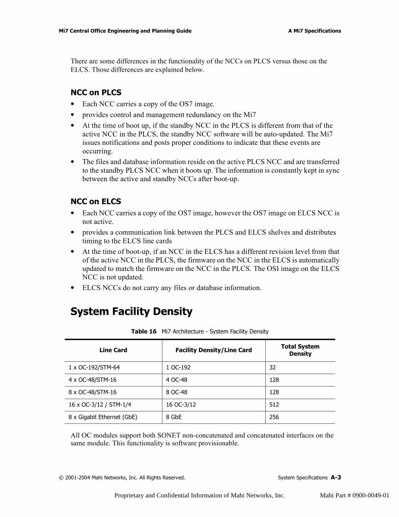
Mi7 Central Office Engineering and Planning Guide A Mi7 Specifications
There are some differences in the functionality of the NCCs on PLCS versus those on the ELCS. Those differences are explained below.
NCC on PLCS• Each NCC carries a copy of the OS7 image.• provides control and management redundancy on the Mi7• At the time of boot up, if the standby NCC in the PLCS is different from that of the
active NCC in the PLCS, the standby NCC software will be auto-updated. The Mi7 issues notifications and posts proper conditions to indicate that these events are occurring.
• The files and database information reside on the active PLCS NCC and are transferred to the standby PLCS NCC when it boots up. The information is constantly kept in sync between the active and standby NCCs after boot-up.
NCC on ELCS• Each NCC carries a copy of the OS7 image, however the OS7 image on ELCS NCC is
not active.• provides a communication link between the PLCS and ELCS shelves and distributes
timing to the ELCS line cards• At the time of boot-up, if an NCC in the ELCS has a different revision level from that
of the active NCC in the PLCS, the firmware on the NCC in the ELCS is automatically updated to match the firmware on the NCC in the PLCS. The OSI image on the ELCS NCC is not updated.
• ELCS NCCs do not carry any files or database information.
System Facility Density
All OC modules support both SONET non-concatenated and concatenated interfaces on the same module. This functionality is software provisionable.
Table 16 Mi7 Architecture - System Facility Density
Line Card Facility Density/Line Card Total System Density
1 x OC-192/STM-64 1 OC-192 32
4 x OC-48/STM-16 4 OC-48 128
8 x OC-48/STM-16 8 OC-48 128
16 x OC-3/12 / STM-1/4 16 OC-3/12 512
8 x Gigabit Ethernet (GbE) 8 GbE 256
© 2001-2004 Mahi Networks, Inc. All Rights Reserved. System Specifications A-3
Proprietary and Confidential Information of Mahi Networks, Inc. Mahi Part # 0900-0049-01
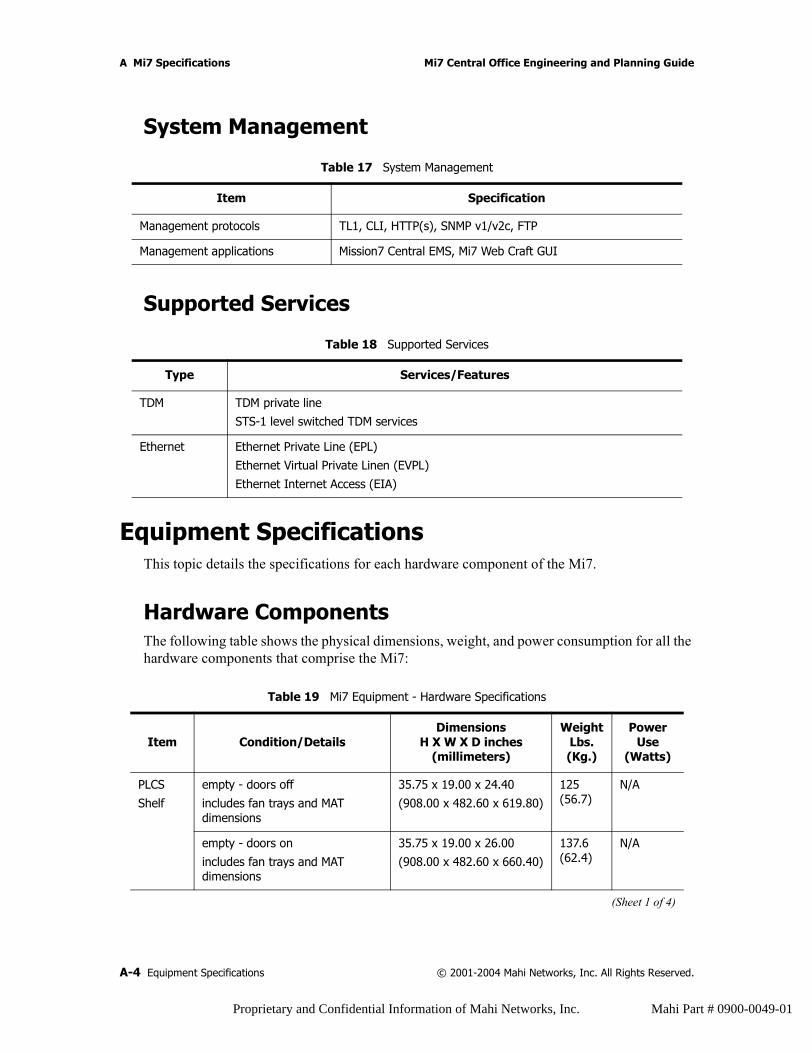
A Mi7 Specifications Mi7 Central Office Engineering and Planning Guide
System Management
Supported Services
Equipment SpecificationsThis topic details the specifications for each hardware component of the Mi7.
Hardware Components The following table shows the physical dimensions, weight, and power consumption for all the hardware components that comprise the Mi7:
Table 17 System Management
Item Specification
Management protocols TL1, CLI, HTTP(s), SNMP v1/v2c, FTP
Management applications Mission7 Central EMS, Mi7 Web Craft GUI
Table 18 Supported Services
Type Services/Features
TDM TDM private line
STS-1 level switched TDM services
Ethernet Ethernet Private Line (EPL)
Ethernet Virtual Private Linen (EVPL)
Ethernet Internet Access (EIA)
Table 19 Mi7 Equipment - Hardware Specifications
Item Condition/DetailsDimensions
H X W X D inches(millimeters)
Weight Lbs. (Kg.)
Power Use
(Watts)
PLCS
Shelf
empty - doors off
includes fan trays and MAT dimensions
35.75 x 19.00 x 24.40
(908.00 x 482.60 x 619.80)
125 (56.7)
N/A
empty - doors on
includes fan trays and MAT dimensions
35.75 x 19.00 x 26.00
(908.00 x 482.60 x 660.40)
137.6 (62.4)
N/A
(Sheet 1 of 4)
A-4 Equipment Specifications © 2001-2004 Mahi Networks, Inc. All Rights Reserved.
Proprietary and Confidential Information of Mahi Networks, Inc. Mahi Part # 0900-0049-01
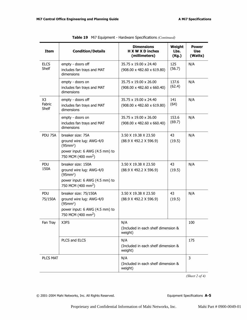
Mi7 Central Office Engineering and Planning Guide A Mi7 Specifications
ELCS Shelf
empty - doors off
includes fan trays and MAT dimensions
35.75 x 19.00 x 24.40
(908.00 x 482.60 x 619.80)
125 (56.7)
N/A
empty - doors onincludes fan trays and MAT dimensions
35.75 x 19.00 x 26.00(908.00 x 482.60 x 660.40)
137.6 (62.4)
N/A
X3 Fabric Shelf
empty - doors off
includes fan trays and MAT dimensions
35.75 x 19.00 x 24.40
(908.00 x 482.60 x 619.80)
141 (64)
N/A
empty - doors on
includes fan trays and MAT dimensions
35.75 x 19.00 x 26.00
(908.00 x 482.60 x 660.40)
153.6 (69.7)
N/A
PDU 75A breaker size: 75Aground wire lug: AWG-4/0 (95mm2)
power input: 6 AWG (4.5 mm) to 750 MCM (400 mm2)
3.50 X 19.38 X 23.50 (88.9 X 492.2 X 596.9)
43(19.5)
N/A
PDU 150A
breaker size: 150A
ground wire lug: AWG-4/0 (95mm2)
power input: 6 AWG (4.5 mm) to 750 MCM (400 mm2)
3.50 X 19.38 X 23.50
(88.9 X 492.2 X 596.9)
43
(19.5)
N/A
PDU 75/150A
breaker size: 75/150Aground wire lug: AWG-4/0 (95mm2)
power input: 6 AWG (4.5 mm) to 750 MCM (400 mm2)
3.50 X 19.38 X 23.50 (88.9 X 492.2 X 596.9)
43(19.5)
N/A
Fan Tray X3FS N/A
(Included in each shelf dimension & weight)
100
PLCS and ELCS N/A(Included in each shelf dimension & weight)
175
PLCS MAT N/A
(Included in each shelf dimension & weight)
3
Table 19 Mi7 Equipment - Hardware Specifications (Continued)
Item Condition/DetailsDimensions
H X W X D inches(millimeters)
Weight Lbs. (Kg.)
Power Use
(Watts)
(Sheet 2 of 4)
© 2001-2004 Mahi Networks, Inc. All Rights Reserved. Equipment Specifications A-5
Proprietary and Confidential Information of Mahi Networks, Inc. Mahi Part # 0900-0049-01
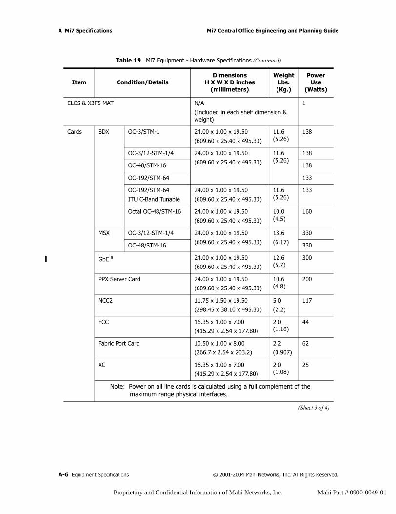
A Mi7 Specifications Mi7 Central Office Engineering and Planning Guide
ELCS & X3FS MAT N/A
(Included in each shelf dimension & weight)
1
Cards SDX OC-3/STM-1 24.00 x 1.00 x 19.50
(609.60 x 25.40 x 495.30)
11.6 (5.26)
138
OC-3/12-STM-1/4 24.00 x 1.00 x 19.50
(609.60 x 25.40 x 495.30)
11.6 (5.26)
138
OC-48/STM-16 138
OC-192/STM-64 133
OC-192/STM-64
ITU C-Band Tunable
24.00 x 1.00 x 19.50
(609.60 x 25.40 x 495.30)
11.6 (5.26)
133
Octal OC-48/STM-16 24.00 x 1.00 x 19.50
(609.60 x 25.40 x 495.30)
10.0 (4.5)
160
MSX OC-3/12-STM-1/4 24.00 x 1.00 x 19.50
(609.60 x 25.40 x 495.30)
13.6
(6.17)
330
OC-48/STM-16 330
GbE a 24.00 x 1.00 x 19.50
(609.60 x 25.40 x 495.30)
12.6 (5.7)
300
PPX Server Card 24.00 x 1.00 x 19.50
(609.60 x 25.40 x 495.30)
10.6 (4.8)
200
NCC2 11.75 x 1.50 x 19.50
(298.45 x 38.10 x 495.30)
5.0
(2.2)
117
FCC 16.35 x 1.00 x 7.00
(415.29 x 2.54 x 177.80)
2.0 (1.18)
44
Fabric Port Card 10.50 x 1.00 x 8.00
(266.7 x 2.54 x 203.2)
2.2
(0.907)
62
XC 16.35 x 1.00 x 7.00
(415.29 x 2.54 x 177.80)
2.0 (1.08)
25
Note: Power on all line cards is calculated using a full complement of the maximum range physical interfaces.
Table 19 Mi7 Equipment - Hardware Specifications (Continued)
Item Condition/DetailsDimensions
H X W X D inches(millimeters)
Weight Lbs. (Kg.)
Power Use
(Watts)
(Sheet 3 of 4)
A-6 Equipment Specifications © 2001-2004 Mahi Networks, Inc. All Rights Reserved.
Proprietary and Confidential Information of Mahi Networks, Inc. Mahi Part # 0900-0049-01
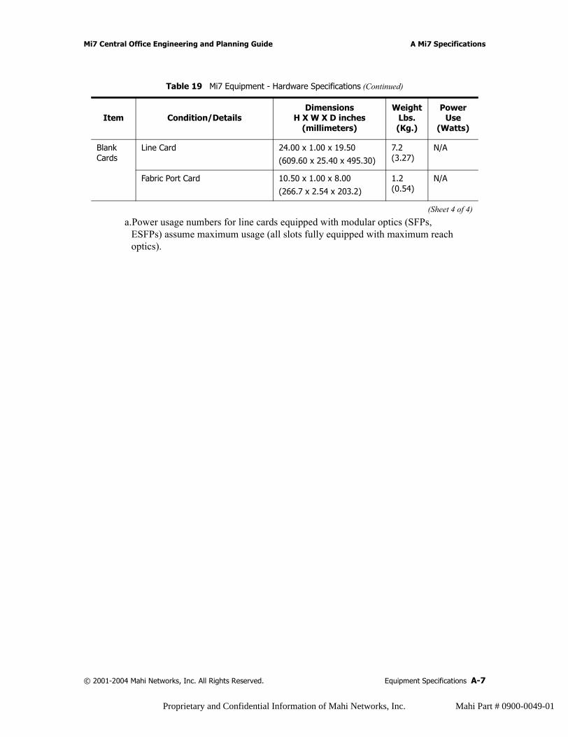
Mi7 Central Office Engineering and Planning Guide A Mi7 Specifications
Blank Cards
Line Card 24.00 x 1.00 x 19.50
(609.60 x 25.40 x 495.30)
7.2 (3.27)
N/A
Fabric Port Card 10.50 x 1.00 x 8.00
(266.7 x 2.54 x 203.2)
1.2 (0.54)
N/A
a.Power usage numbers for line cards equipped with modular optics (SFPs, ESFPs) assume maximum usage (all slots fully equipped with maximum reach optics).
Table 19 Mi7 Equipment - Hardware Specifications (Continued)
Item Condition/DetailsDimensions
H X W X D inches(millimeters)
Weight Lbs. (Kg.)
Power Use
(Watts)
(Sheet 4 of 4)
© 2001-2004 Mahi Networks, Inc. All Rights Reserved. Equipment Specifications A-7
Proprietary and Confidential Information of Mahi Networks, Inc. Mahi Part # 0900-0049-01
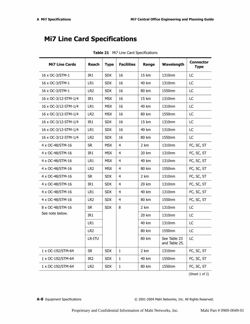
A Mi7 Specifications Mi7 Central Office Engineering and Planning Guide
Mi7 Line Card Specifications
Table 21 Mi7 Line Card Specifications
Mi7 Line Cards Reach Type Facilities Range Wavelength Connector Type
16 x OC-3/STM-1 IR1 SDX 16 15 km 1310nm LC
16 x OC-3/STM-1 LR1 SDX 16 40 km 1310nm LC
16 x OC-3/STM-1 LR2 SDX 16 80 km 1550nm LC
16 x OC-3/12-STM-1/4 IR1 MSX 16 15 km 1310nm LC
16 x OC-3/12-STM-1/4 LR1 MSX 16 40 km 1310nm LC
16 x OC-3/12-STM-1/4 LR2 MSX 16 80 km 1550nm LC
16 x OC-3/12-STM-1/4 IR1 SDX 16 15 km 1310nm LC
16 x OC-3/12-STM-1/4 LR1 SDX 16 40 km 1310nm LC
16 x OC-3/12-STM-1/4 LR2 SDX 16 80 km 1550nm LC
4 x OC-48/STM-16 SR MSX 4 2 km 1310nm FC, SC, ST
4 x OC-48/STM-16 IR1 MSX 4 20 km 1310nm FC, SC, ST
4 x OC-48/STM-16 LR1 MSX 4 40 km 1310nm FC, SC, ST
4 x OC-48/STM-16 LR2 MSX 4 80 km 1550nm FC, SC, ST
4 x OC-48/STM-16 SR SDX 4 2 km 1310nm FC, SC, ST
4 x OC-48/STM-16 IR1 SDX 4 20 km 1310nm FC, SC, ST
4 x OC-48/STM-16 LR1 SDX 4 40 km 1310nm FC, SC, ST
4 x OC-48/STM-16 LR2 SDX 4 80 km 1550nm FC, SC, ST
8 x OC-48/STM-16
See note below.SR SDX 8 2 km 1310nm LC
IR1 20 km 1310nm LC
LR1 40 km 1310nm LC
LR2 80 km 1550nm LC
LR-ITU 80 km See Table 23 and Table 25.
LC
1 x OC-192/STM-64 SR SDX 1 2 km 1310nm FC, SC, ST
1 x OC-192/STM-64 IR2 SDX 1 40 km 1550nm FC, SC, ST
1 x OC-192/STM-64 LR2 SDX 1 80 km 1550nm FC, SC, ST
(Sheet 1 of 2)
A-8 Equipment Specifications © 2001-2004 Mahi Networks, Inc. All Rights Reserved.
Proprietary and Confidential Information of Mahi Networks, Inc. Mahi Part # 0900-0049-01
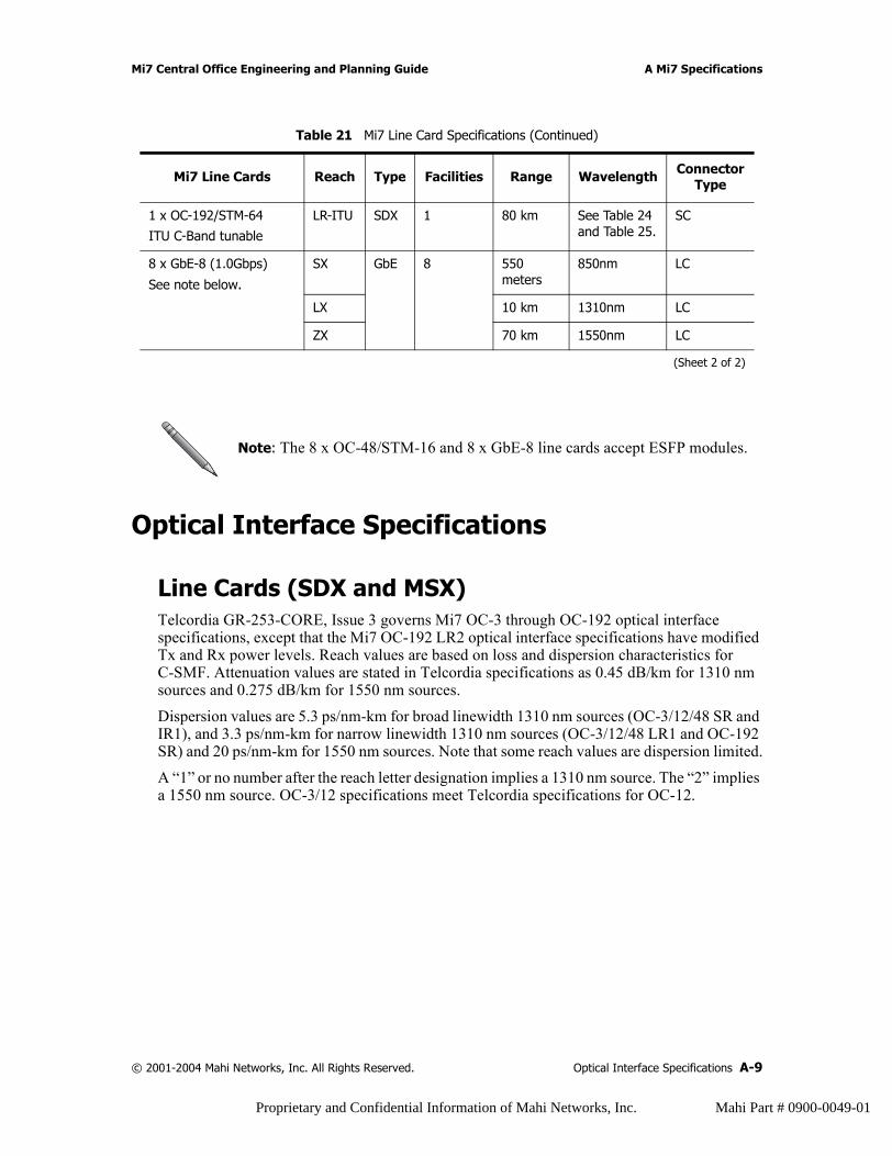
Mi7 Central Office Engineering and Planning Guide A Mi7 Specifications
Optical Interface Specifications
Line Cards (SDX and MSX)Telcordia GR-253-CORE, Issue 3 governs Mi7 OC-3 through OC-192 optical interface specifications, except that the Mi7 OC-192 LR2 optical interface specifications have modified Tx and Rx power levels. Reach values are based on loss and dispersion characteristics for C-SMF. Attenuation values are stated in Telcordia specifications as 0.45 dB/km for 1310 nm sources and 0.275 dB/km for 1550 nm sources.
Dispersion values are 5.3 ps/nm-km for broad linewidth 1310 nm sources (OC-3/12/48 SR and IR1), and 3.3 ps/nm-km for narrow linewidth 1310 nm sources (OC-3/12/48 LR1 and OC-192 SR) and 20 ps/nm-km for 1550 nm sources. Note that some reach values are dispersion limited.
A “1” or no number after the reach letter designation implies a 1310 nm source. The “2” implies a 1550 nm source. OC-3/12 specifications meet Telcordia specifications for OC-12.
1 x OC-192/STM-64
ITU C-Band tunable
LR-ITU SDX 1 80 km See Table 24 and Table 25.
SC
8 x GbE-8 (1.0Gbps)
See note below.SX GbE 8 550
meters850nm LC
LX 10 km 1310nm LC
ZX 70 km 1550nm LC
Note: The 8 x OC-48/STM-16 and 8 x GbE-8 line cards accept ESFP modules.
Table 21 Mi7 Line Card Specifications (Continued)
Mi7 Line Cards Reach Type Facilities Range Wavelength Connector Type
(Sheet 2 of 2)
© 2001-2004 Mahi Networks, Inc. All Rights Reserved. Optical Interface Specifications A-9
Proprietary and Confidential Information of Mahi Networks, Inc. Mahi Part # 0900-0049-01
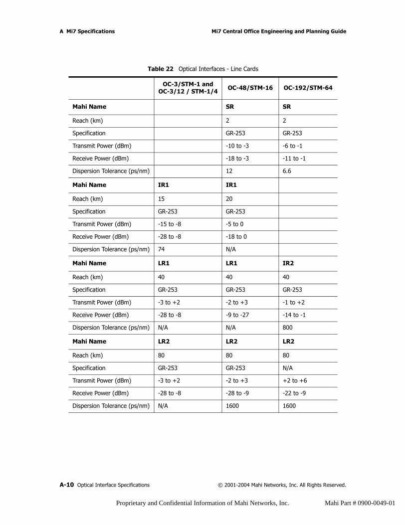
A Mi7 Specifications Mi7 Central Office Engineering and Planning Guide
Table 22 Optical Interfaces - Line Cards
OC-3/STM-1 and OC-3/12 / STM-1/4 OC-48/STM-16 OC-192/STM-64
Mahi Name SR SR
Reach (km) 2 2
Specification GR-253 GR-253
Transmit Power (dBm) -10 to -3 -6 to -1
Receive Power (dBm) -18 to -3 -11 to -1
Dispersion Tolerance (ps/nm) 12 6.6
Mahi Name IR1 IR1
Reach (km) 15 20
Specification GR-253 GR-253
Transmit Power (dBm) -15 to -8 -5 to 0
Receive Power (dBm) -28 to -8 -18 to 0
Dispersion Tolerance (ps/nm) 74 N/A
Mahi Name LR1 LR1 IR2
Reach (km) 40 40 40
Specification GR-253 GR-253 GR-253
Transmit Power (dBm) -3 to +2 -2 to +3 -1 to +2
Receive Power (dBm) -28 to -8 -9 to -27 -14 to -1
Dispersion Tolerance (ps/nm) N/A N/A 800
Mahi Name LR2 LR2 LR2
Reach (km) 80 80 80
Specification GR-253 GR-253 N/A
Transmit Power (dBm) -3 to +2 -2 to +3 +2 to +6
Receive Power (dBm) -28 to -8 -28 to -9 -22 to -9
Dispersion Tolerance (ps/nm) N/A 1600 1600
A-10 Optical Interface Specifications © 2001-2004 Mahi Networks, Inc. All Rights Reserved.
Proprietary and Confidential Information of Mahi Networks, Inc. Mahi Part # 0900-0049-01

Mi7 Central Office Engineering and Planning Guide A Mi7 Specifications
OC-48 and OC-192 ITU Grid Optical Parameters
Table 23 OC-48 ITU Grid Optical Parameters
Reach type LR-ITU
Tx power 0 to +4 dBm
Rx Power Sensitivity -28 to -8 dBm
Path Penalty 2 dB
Wavelength Stability 12.5 GHz
Linewidth (20 dB) 0.3 nm
Dispersion Penalty 2 dBm
Dispersion Tolerance 1600 ps/nm
Side Mode Suppression Ratio (SMSR) 30 dB
Extinction Ration (ER) 8.2 dB
Receiver Reflectance -27 dB
Optical Signal/Noise Ratio (OSNR) 20 dB
Receiver Sensitivity at OSNR -27 dBm
Table 24 OC-192 ITU Grid Optical Parameters
Reach type LR-ITU
Tx power +4 to +7 dBm
Rx Power Sensitivity -24 to -7 dBm
Path Penalty 2 dB
Wavelength Stability 2.5 GHz
Linewidth (20 dB) 0.2 nm
Dispersion Penalty 2 dBm
Dispersion Tolerance 1600 ps/nm
Side Mode Suppression Ratio (SMSR) 40 dB
Extinction Ration (ER) 12 dB
Receiver Reflectance -27 dB
Optical Signal/Noise Ratio (OSNR) 19 dB
Receiver Sensitivity at OSNR -20 dBm
© 2001-2004 Mahi Networks, Inc. All Rights Reserved. Optical Interface Specifications A-11
Proprietary and Confidential Information of Mahi Networks, Inc. Mahi Part # 0900-0049-01

A Mi7 Specifications Mi7 Central Office Engineering and Planning Guide
ITU Grid Optics Channel Plan
Table 25 ITU GRID, C Band, 100 GHz Spacing
FREQ λ ITU
CH ID (THz) (nm) # Initial Channels Growth Channels
1 195.9 1530.33 59 X
2 195.8 1531.12 58 X
3 195.7 1531.9 57 X
4 195.6 1532.68 56 X
5 195.5 1533.47 55 X
6 195.4 1534.25 54 X
7 195.3 1535.04 53 X
8 195.2 1535.82 52 X
9 195.1 1536.61 51
10 195 1537.4 50
11 194.9 1538.19 49 X
12 194.8 1538.98 48 X
13 194.7 1539.77 47 X
14 194.6 1540.56 46 X
15 194.5 1541.35 45 X
16 194.4 1542.14 44 X
17 194.3 1542.94 43 X
18 194.2 1543.73 42 X
19 194.1 1544.53 41
20 194 1545.32 40
21 193.9 1546.12 39
22 193.8 1546.92 38 X
23 193.7 1547.72 37 X
24 193.6 1548.51 36 X
25 193.5 1549.32 35 X
26 193.4 1550.12 34 X
(Sheet 1 of 2)
A-12 Optical Interface Specifications © 2001-2004 Mahi Networks, Inc. All Rights Reserved.
Proprietary and Confidential Information of Mahi Networks, Inc. Mahi Part # 0900-0049-01
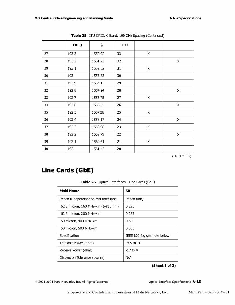
Mi7 Central Office Engineering and Planning Guide A Mi7 Specifications
Line Cards (GbE)
27 193.3 1550.92 33 X
28 193.2 1551.72 32 X
29 193.1 1552.52 31 X
30 193 1553.33 30
31 192.9 1554.13 29
32 192.8 1554.94 28 X
33 192.7 1555.75 27 X
34 192.6 1556.55 26 X
35 192.5 1557.36 25 X
36 192.4 1558.17 24 X
37 192.3 1558.98 23 X
38 192.2 1559.79 22 X
39 192.1 1560.61 21 X
40 192 1561.42 20
Table 26 Optical Interfaces - Line Cards (GbE)
Mahi Name SX
Reach is dependant on MM fiber type: Reach (km)
62.5 micron, 160 MHz-km (@850 nm) 0.220
62.5 micron, 200 MHz-km 0.275
50 micron, 400 MHz-km 0.500
50 micron, 500 MHz-km 0.550
Specification IEEE 802.3z, see note below
Transmit Power (dBm) -9.5 to -4
Receive Power (dBm) -17 to 0
Dispersion Tolerance (ps/nm) N/A
(Sheet 1 of 2)
Table 25 ITU GRID, C Band, 100 GHz Spacing (Continued)
FREQ λ ITU
(Sheet 2 of 2)
© 2001-2004 Mahi Networks, Inc. All Rights Reserved. Optical Interface Specifications A-13
Proprietary and Confidential Information of Mahi Networks, Inc. Mahi Part # 0900-0049-01

A Mi7 Specifications Mi7 Central Office Engineering and Planning Guide
Mahi Name LX
Reach (km) 10
Specification IEEE 802.3z, see note below
Transmit Power (dBm) -11 to -3
Receive Power (dBm) -19 to -3
Dispersion Tolerance (ps/nm) -5.5 to 5
Mahi Name ZX
Reach (km) 70
Specification See note below
Transmit Power (dBm) -3 to +3
Receive Power (dBm) -23.5 to -3
Dispersion Tolerance (ps/nm) 1400
Note: There is no IEEE specification for ZX.
Mahi Networks Inc. has created an internal specifications document to define ZX based on what is available from vendors as well as to clarify some of the IEEE specifications.
Table 26 Optical Interfaces - Line Cards (GbE) (Continued)
(Sheet 2 of 2)
A-14 Optical Interface Specifications © 2001-2004 Mahi Networks, Inc. All Rights Reserved.
Proprietary and Confidential Information of Mahi Networks, Inc. Mahi Part # 0900-0049-01
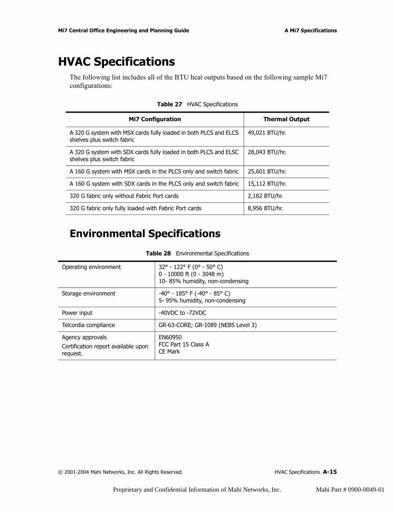
Mi7 Central Office Engineering and Planning Guide A Mi7 Specifications
HVAC SpecificationsThe following list includes all of the BTU heat outputs based on the following sample Mi7 configurations:
Environmental Specifications
Table 27 HVAC Specifications
Mi7 Configuration Thermal Output
A 320 G system with MSX cards fully loaded in both PLCS and ELCS shelves plus switch fabric
49,021 BTU/hr.
A 320 G system with SDX cards fully loaded in both PLCS and ELSC shelves plus switch fabric
28,043 BTU/hr.
A 160 G system with MSX cards in the PLCS only and switch fabric 25,601 BTU/hr.
A 160 G system with SDX cards in the PLCS only and switch fabric 15,112 BTU/hr.
320 G fabric only without Fabric Port cards 2,182 BTU/hr.
320 G fabric only fully loaded with Fabric Port cards 8,956 BTU/hr.
Table 28 Environmental Specifications
Operating environment 32° - 122° F (0° - 50° C)0 - 10000 ft (0 - 3048 m)10- 85% humidity, non-condensing
Storage environment -40° - 185° F (-40° - 85° C)5- 95% humidity, non-condensing
Power input -40VDC to -72VDC
Telcordia compliance GR-63-CORE; GR-1089 (NEBS Level 3)
Agency approvals
Certification report available upon request.
EN60950FCC Part 15 Class ACE Mark
© 2001-2004 Mahi Networks, Inc. All Rights Reserved. HVAC Specifications A-15
Proprietary and Confidential Information of Mahi Networks, Inc. Mahi Part # 0900-0049-01

A Mi7 Specifications Mi7 Central Office Engineering and Planning Guide
A-16 HVAC Specifications © 2001-2004 Mahi Networks, Inc. All Rights Reserved.
Proprietary and Confidential Information of Mahi Networks, Inc. Mahi Part # 0900-0049-01
B LED Specifications
IntroductionThis appendix details the LED specifications for all components of the Mi7. The content within this appendix is presented as follows:
• LED Displays and Behaviors• Shelf LED Displays• Line Card LEDs Displays and Behaviors
LED Displays and Behaviors The Mi7 has the following LEDs:
• one LED display at the top right of each Primary Line Card Shelf (PLCS), Expansion Line Card Shelf (ELCS), and X3 Fabric Shelf (X3FS).
• LEDs on the faceplates of each type of card in the Mi7.• two power light LEDs, one for each input circuit, on the Power Distribution Unit
(PDU).
© 2001-2004 Mahi Networks, Inc. All Rights Reserved. Introduction B-1
Proprietary and Confidential Information of Mahi Networks, Inc. Mahi Part # 0900-0049-01
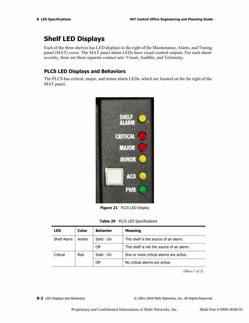
B LED Specifications Mi7 Central Office Engineering and Planning Guide
Shelf LED DisplaysEach of the three shelves has LED displays to the right of the Maintenance, Alarm, and Timing panel (MAT) cover. The MAT panel alarm LEDs have visual control outputs. For each alarm severity, there are three separate contact sets: Visual, Audible, and Telemetry.
PLCS LED Displays and Behaviors The PLCS has critical, major, and minor alarm LEDs, which are located on the far right of the MAT panel.
Figure 21 PLCS LED Display
Table 29 PLCS LED Specifications
LED Color Behavior Meaning
Shelf Alarm Amber Solid - On This shelf is the source of an alarm.
Off This shelf is not the source of an alarm.
Critical Red Solid - On One or more critical alarms are active.
Off No critical alarms are active.
(Sheet 1 of 2)
B-2 LED Displays and Behaviors © 2001-2004 Mahi Networks, Inc. All Rights Reserved.
Proprietary and Confidential Information of Mahi Networks, Inc. Mahi Part # 0900-0049-01
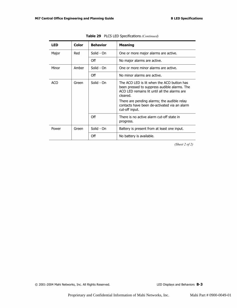
Mi7 Central Office Engineering and Planning Guide B LED Specifications
Major Red Solid - On One or more major alarms are active.
Off No major alarms are active.
Minor Amber Solid - On One or more minor alarms are active.
Off No minor alarms are active.
ACO Green Solid - On The ACO LED is lit when the ACO button has been pressed to suppress audible alarms. The ACO LED remains lit until all the alarms are cleared.
There are pending alarms; the audible relay contacts have been de-activated via an alarm cut-off input.
Off There is no active alarm cut-off state in progress.
Power Green Solid - On Battery is present from at least one input.
Off No battery is available.
Table 29 PLCS LED Specifications (Continued)
LED Color Behavior Meaning
(Sheet 2 of 2)
© 2001-2004 Mahi Networks, Inc. All Rights Reserved. LED Displays and Behaviors B-3
Proprietary and Confidential Information of Mahi Networks, Inc. Mahi Part # 0900-0049-01
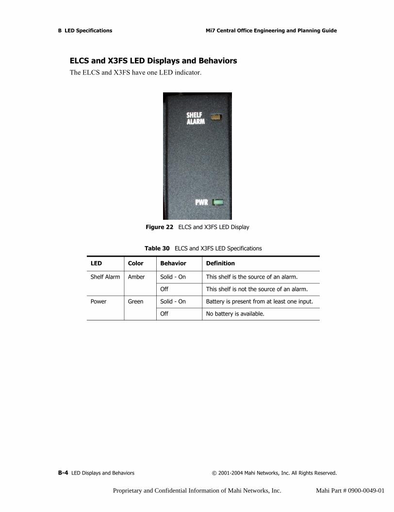
B LED Specifications Mi7 Central Office Engineering and Planning Guide
ELCS and X3FS LED Displays and BehaviorsThe ELCS and X3FS have one LED indicator.
Figure 22 ELCS and X3FS LED Display
Table 30 ELCS and X3FS LED Specifications
LED Color Behavior Definition
Shelf Alarm Amber Solid - On This shelf is the source of an alarm.
Off This shelf is not the source of an alarm.
Power Green Solid - On Battery is present from at least one input.
Off No battery is available.
B-4 LED Displays and Behaviors © 2001-2004 Mahi Networks, Inc. All Rights Reserved.
Proprietary and Confidential Information of Mahi Networks, Inc. Mahi Part # 0900-0049-01
Mi7 Central Office Engineering and Planning Guide B LED Specifications
Line Card LEDs Displays and BehaviorsEach Mi7 card has LEDs that indicate card or circuit status.
OC-3/STM-1The OC-3/STM-1 line card has one RUN LED tri-colored (green/red/amber) status LED on the faceplate:
• Fast flashing green indicates the card is initializing or is in self test.• Slow flashing green indicates that the card has been provisioned out of service.• Solid green indicates the line card is In-Service Normal (IS-NR) or plugged in, but not
provisioned.• Red indicates the card has failed its self diagnostic and needs to be replaced.• Solid Amber indicates there is a loss of signal (LOS) on one or more facilities.• Flashing Amber indicates the card firmware is out of date, and/or is being automatically
updated.
© 2001-2004 Mahi Networks, Inc. All Rights Reserved. LED Displays and Behaviors B-5
Proprietary and Confidential Information of Mahi Networks, Inc. Mahi Part # 0900-0049-01
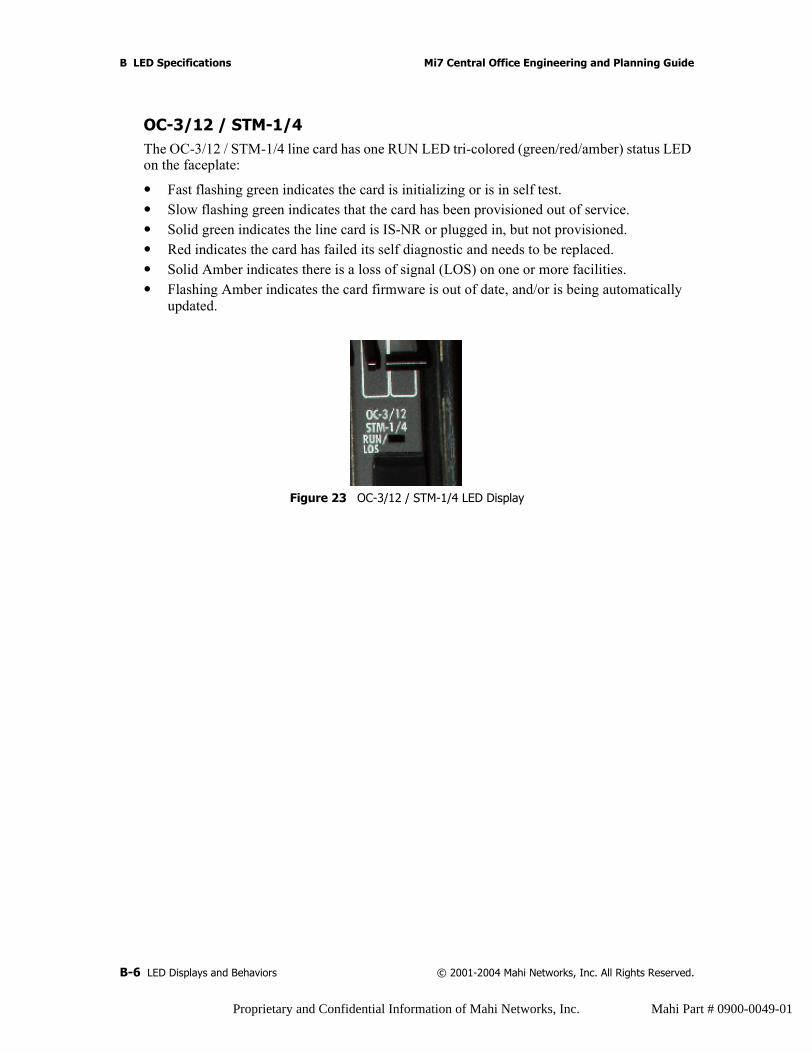
B LED Specifications Mi7 Central Office Engineering and Planning Guide
OC-3/12 / STM-1/4The OC-3/12 / STM-1/4 line card has one RUN LED tri-colored (green/red/amber) status LED on the faceplate:
• Fast flashing green indicates the card is initializing or is in self test.• Slow flashing green indicates that the card has been provisioned out of service.• Solid green indicates the line card is IS-NR or plugged in, but not provisioned.• Red indicates the card has failed its self diagnostic and needs to be replaced.• Solid Amber indicates there is a loss of signal (LOS) on one or more facilities.• Flashing Amber indicates the card firmware is out of date, and/or is being automatically
updated.
Figure 23 OC-3/12 / STM-1/4 LED Display
B-6 LED Displays and Behaviors © 2001-2004 Mahi Networks, Inc. All Rights Reserved.
Proprietary and Confidential Information of Mahi Networks, Inc. Mahi Part # 0900-0049-01
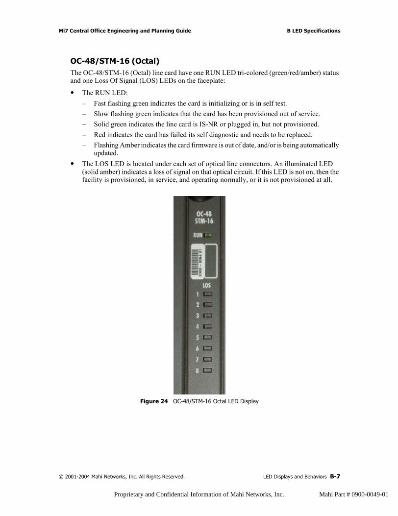
Mi7 Central Office Engineering and Planning Guide B LED Specifications
OC-48/STM-16 (Octal)The OC-48/STM-16 (Octal) line card have one RUN LED tri-colored (green/red/amber) status and one Loss Of Signal (LOS) LEDs on the faceplate:
• The RUN LED:– Fast flashing green indicates the card is initializing or is in self test.– Slow flashing green indicates that the card has been provisioned out of service.– Solid green indicates the line card is IS-NR or plugged in, but not provisioned.– Red indicates the card has failed its self diagnostic and needs to be replaced.– Flashing Amber indicates the card firmware is out of date, and/or is being automatically
updated.• The LOS LED is located under each set of optical line connectors. An illuminated LED
(solid amber) indicates a loss of signal on that optical circuit. If this LED is not on, then the facility is provisioned, in service, and operating normally, or it is not provisioned at all.
Figure 24 OC-48/STM-16 Octal LED Display
© 2001-2004 Mahi Networks, Inc. All Rights Reserved. LED Displays and Behaviors B-7
Proprietary and Confidential Information of Mahi Networks, Inc. Mahi Part # 0900-0049-01
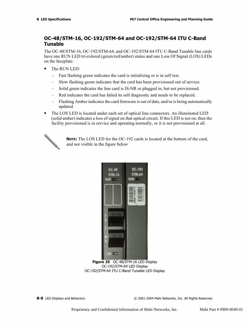
B LED Specifications Mi7 Central Office Engineering and Planning Guide
OC-48/STM-16, OC-192/STM-64 and OC-192/STM-64 ITU C-Band TunableThe OC-48/STM-16, OC-192/STM-64, and OC-192/STM-64 ITU C-Band Tunable line cards have one RUN LED tri-colored (green/red/amber) status and one Loss Of Signal (LOS) LEDs on the faceplate:
• The RUN LED:– Fast flashing green indicates the card is initializing or is in self test.– Slow flashing green indicates that the card has been provisioned out of service.– Solid green indicates the line card is IS-NR or plugged in, but not provisioned.– Red indicates the card has failed its self diagnostic and needs to be replaced.– Flashing Amber indicates the card firmware is out of date, and/or is being automatically
updated.• The LOS LED is located under each set of optical line connectors. An illuminated LED
(solid amber) indicates a loss of signal on that optical circuit. If this LED is not on, then the facility provisioned is in service and operating normally, or it is not provisioned at all.
Figure 25 OC-48/STM-16 LED DisplayOC-192/STM-64 LED Display
OC-192/STM-64 ITU C-Band Tunable LED Display
NOTE: The LOS LED for the OC-192 cards is located at the bottom of the card, and not visible in the figure below
B-8 LED Displays and Behaviors © 2001-2004 Mahi Networks, Inc. All Rights Reserved.
Proprietary and Confidential Information of Mahi Networks, Inc. Mahi Part # 0900-0049-01

Mi7 Central Office Engineering and Planning Guide B LED Specifications
GbE The GbE line cards have one RUN LED tri-colored (green/red/amber) status and one Link LEDs on the faceplate:
• The RUN LED:– Fast flashing green indicates the card is initializing or is in self test.– Slow flashing green indicates that the card has been provisioned out of service.– Solid green indicates the line card is IS-NR or plugged in, but not provisioned.– Red indicates the card has failed its self diagnostic and needs to be replaced.– Flashing Amber indicates the card’s firmware is out of date and is being automatically
updated.• The LINK LED, when illuminated (solid green) indicates that the GbE link, as defined in
IEEE 802.3, is working properly. When not lit, the link status is Fail as defined in IEEE 802.3.
Figure 26 GbE LED Display
© 2001-2004 Mahi Networks, Inc. All Rights Reserved. LED Displays and Behaviors B-9
Proprietary and Confidential Information of Mahi Networks, Inc. Mahi Part # 0900-0049-01
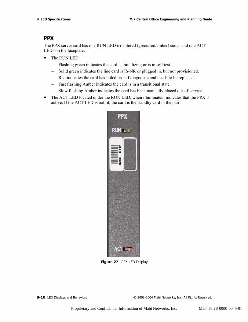
B LED Specifications Mi7 Central Office Engineering and Planning Guide
PPXThe PPX server card has one RUN LED tri-colored (green/red/amber) status and one ACT LEDs on the faceplate:
• The RUN LED:– Flashing green indicates the card is initializing or is in self test.– Solid green indicates the line card is IS-NR or plugged in, but not provisioned.– Red indicates the card has failed its self diagnostic and needs to be replaced.– Fast flashing Amber indicates the card is in a transitional state.– Slow flashing Amber indicates the card has been manually placed out-of-service.
• The ACT LED located under the RUN LED, when illuminated, indicates that the PPX is active. If the ACT LED is not lit, the card is the standby card in the pair.
Figure 27 PPX LED Display
B-10 LED Displays and Behaviors © 2001-2004 Mahi Networks, Inc. All Rights Reserved.
Proprietary and Confidential Information of Mahi Networks, Inc. Mahi Part # 0900-0049-01
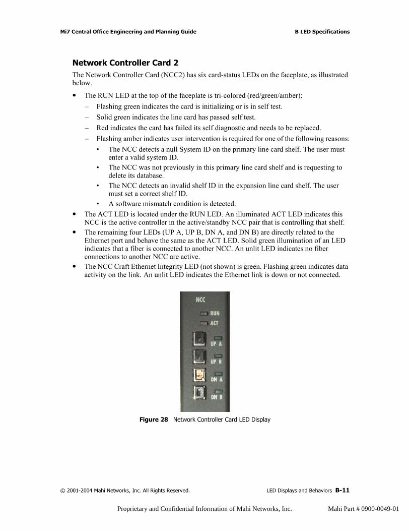
Mi7 Central Office Engineering and Planning Guide B LED Specifications
Network Controller Card 2The Network Controller Card (NCC2) has six card-status LEDs on the faceplate, as illustrated below.
• The RUN LED at the top of the faceplate is tri-colored (red/green/amber):– Flashing green indicates the card is initializing or is in self test.– Solid green indicates the line card has passed self test.– Red indicates the card has failed its self diagnostic and needs to be replaced.– Flashing amber indicates user intervention is required for one of the following reasons:
• The NCC detects a null System ID on the primary line card shelf. The user must enter a valid system ID.
• The NCC was not previously in this primary line card shelf and is requesting to delete its database.
• The NCC detects an invalid shelf ID in the expansion line card shelf. The user must set a correct shelf ID.
• A software mismatch condition is detected.• The ACT LED is located under the RUN LED. An illuminated ACT LED indicates this
NCC is the active controller in the active/standby NCC pair that is controlling that shelf.• The remaining four LEDs (UP A, UP B, DN A, and DN B) are directly related to the
Ethernet port and behave the same as the ACT LED. Solid green illumination of an LED indicates that a fiber is connected to another NCC. An unlit LED indicates no fiber connections to another NCC are active.
• The NCC Craft Ethernet Integrity LED (not shown) is green. Flashing green indicates data activity on the link. An unlit LED indicates the Ethernet link is down or not connected.
Figure 28 Network Controller Card LED Display
© 2001-2004 Mahi Networks, Inc. All Rights Reserved. LED Displays and Behaviors B-11
Proprietary and Confidential Information of Mahi Networks, Inc. Mahi Part # 0900-0049-01
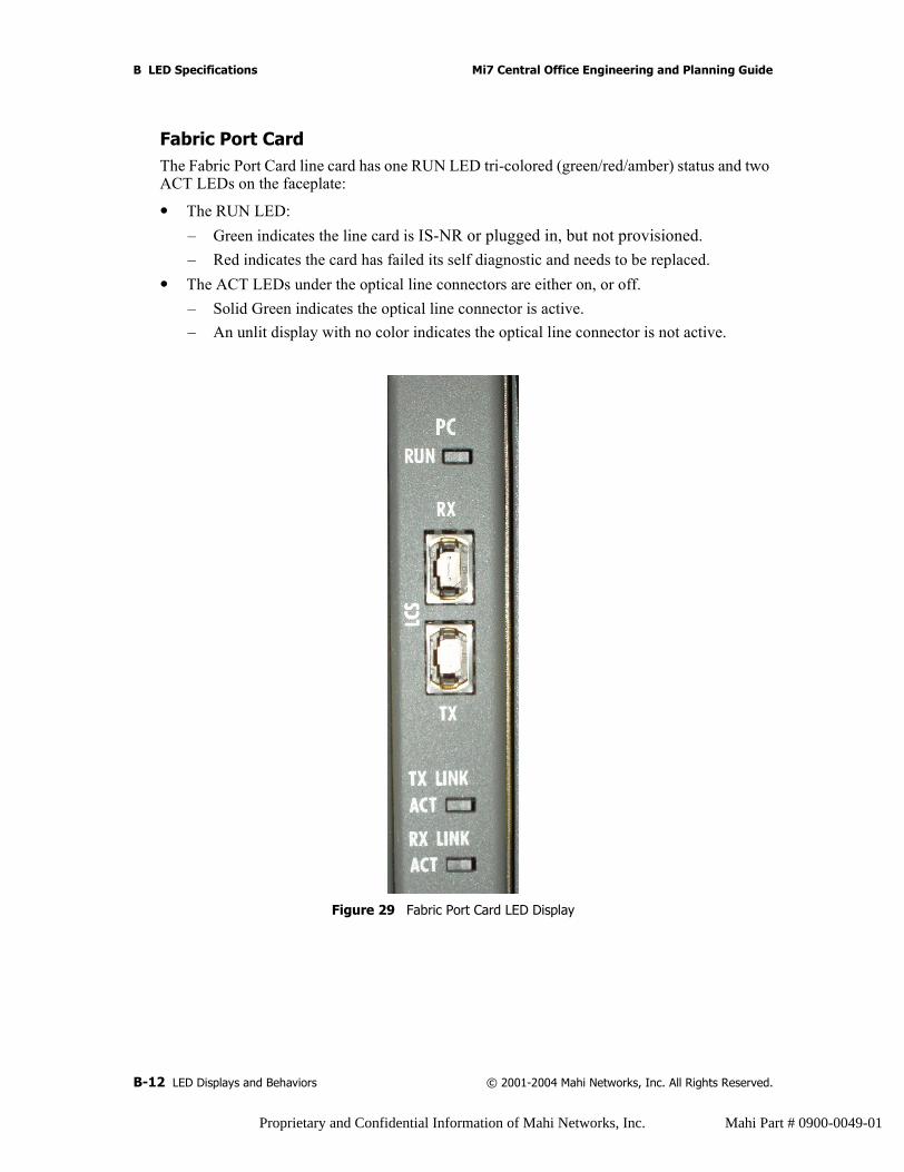
B LED Specifications Mi7 Central Office Engineering and Planning Guide
Fabric Port CardThe Fabric Port Card line card has one RUN LED tri-colored (green/red/amber) status and two ACT LEDs on the faceplate:
• The RUN LED:– Green indicates the line card is IS-NR or plugged in, but not provisioned.– Red indicates the card has failed its self diagnostic and needs to be replaced.
• The ACT LEDs under the optical line connectors are either on, or off. – Solid Green indicates the optical line connector is active.– An unlit display with no color indicates the optical line connector is not active.
Figure 29 Fabric Port Card LED Display
B-12 LED Displays and Behaviors © 2001-2004 Mahi Networks, Inc. All Rights Reserved.
Proprietary and Confidential Information of Mahi Networks, Inc. Mahi Part # 0900-0049-01
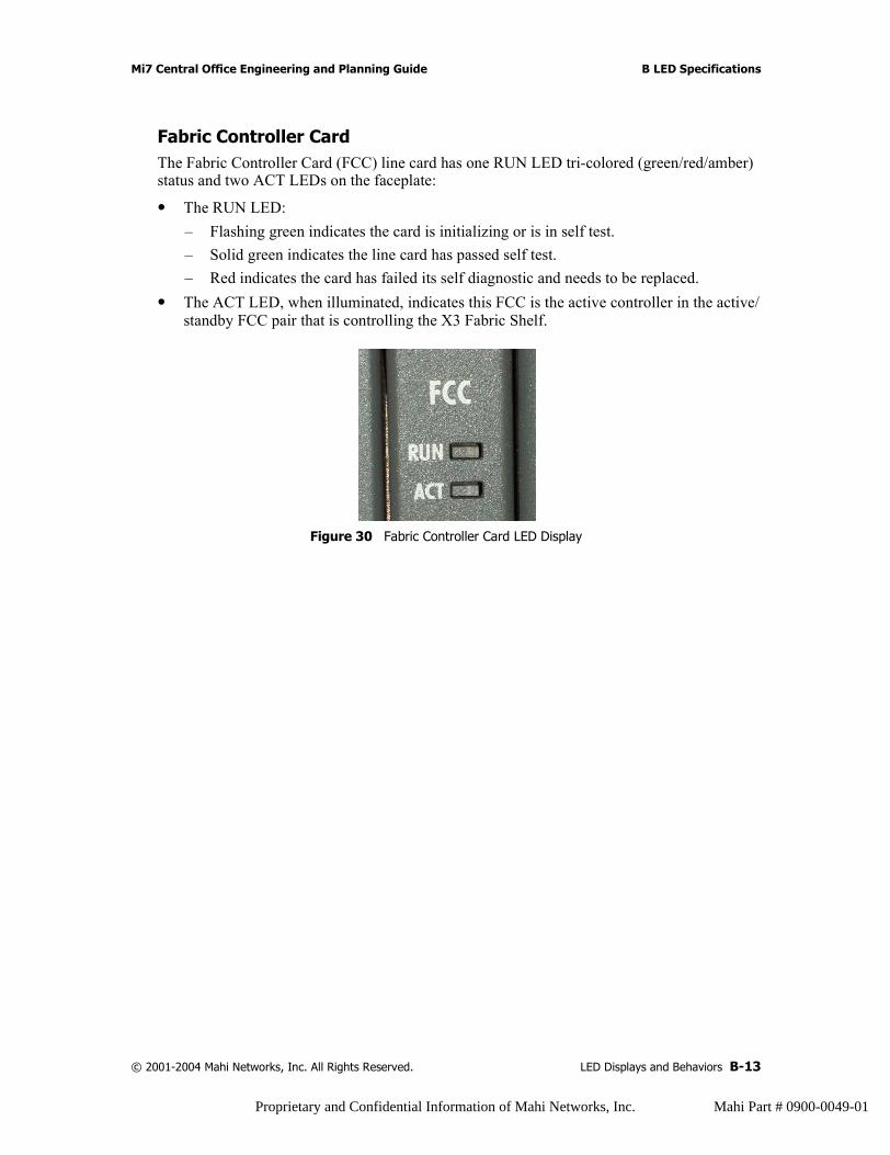
Mi7 Central Office Engineering and Planning Guide B LED Specifications
Fabric Controller CardThe Fabric Controller Card (FCC) line card has one RUN LED tri-colored (green/red/amber) status and two ACT LEDs on the faceplate:
• The RUN LED:– Flashing green indicates the card is initializing or is in self test.– Solid green indicates the line card has passed self test.– Red indicates the card has failed its self diagnostic and needs to be replaced.
• The ACT LED, when illuminated, indicates this FCC is the active controller in the active/standby FCC pair that is controlling the X3 Fabric Shelf.
Figure 30 Fabric Controller Card LED Display
© 2001-2004 Mahi Networks, Inc. All Rights Reserved. LED Displays and Behaviors B-13
Proprietary and Confidential Information of Mahi Networks, Inc. Mahi Part # 0900-0049-01
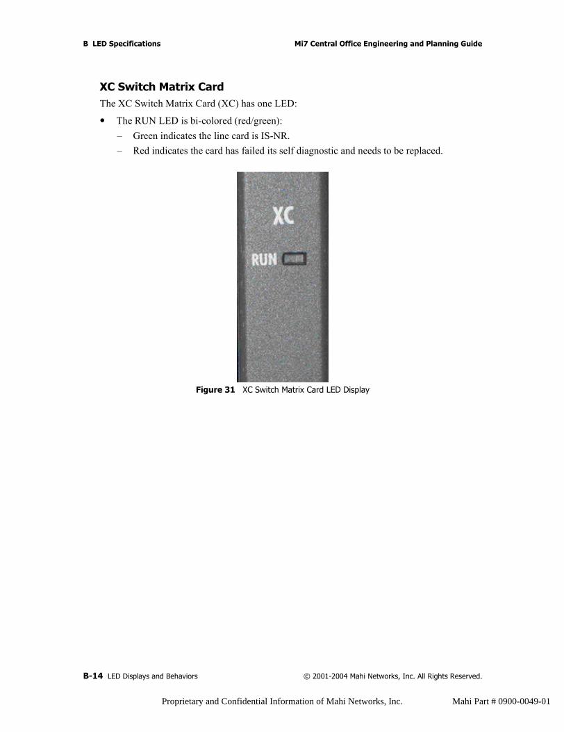
B LED Specifications Mi7 Central Office Engineering and Planning Guide
XC Switch Matrix CardThe XC Switch Matrix Card (XC) has one LED:
• The RUN LED is bi-colored (red/green):– Green indicates the line card is IS-NR.– Red indicates the card has failed its self diagnostic and needs to be replaced.
Figure 31 XC Switch Matrix Card LED Display
B-14 LED Displays and Behaviors © 2001-2004 Mahi Networks, Inc. All Rights Reserved.
Proprietary and Confidential Information of Mahi Networks, Inc. Mahi Part # 0900-0049-01

C List of Acronyms
Numbers
2FTwo-Fiber
4FFour-Fiber
A
AAAAuthentication, Authorization, and Accounting
ACOAlarm Cut Off
ACLAccess Control List
ACTActive (Secondary State)
ADMAdd/Drop Multiplexer
AIDAccess Identifier
AISAlarm Indicating Signal
ALSAutomatic Laser Shutoff
APSAutomatic Protection Switching
ARCAlarm Reporting Control
ARPAddress Resolution Protocol
ASICApplication Specific Integrated Circuit
ATMAsynchronous Transfer Mode
ATNAutomated Transport Networking
AWGAmerican Wire Gauge
B
BB DCSBroadband Digital Cross Connect System
BGPBorder Gateway Protocol
BITSBuilding Integrated Timing Supply
BLSRBidirectional Line Switched Ring
C
CACConnection Admission Control
CAPEX
CLICommand Line Interface
COCentral Office
© 2001-2004 Mahi Networks, Inc. All Rights Reserved. C-1
Proprietary and Confidential Information of Mahi Networks, Inc. Mahi Part # 0900-0049-01
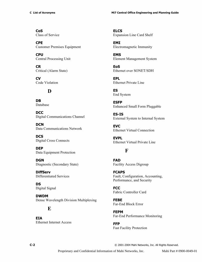
C List of Acronyms Mi7 Central Office Engineering and Planning Guide
CoSClass of Service
CPECustomer Premises Equipment
CPUCentral Processing Unit
CRCritical (Alarm State)
CVCode Violation
D
DBDatabase
DCCDigital Communications Channel
DCNData Communications Network
DCSDigital Cross Connects
DEPData Equipment Protection
DGNDiagnostic (Secondary State)
DiffServDifferentiated Services
DSDigital Signal
DWDMDense Wavelength Division Multiplexing
E
EIAEthernet Internet Access
ELCSExpansion Line Card Shelf
EMIElectromagnetic Immunity
EMSElement Management System
EoSEthernet over SONET/SDH
EPL Ethernet Private Line
ESEnd System
ESFPEnhanced Small Form Pluggable
ES-ISExternal System to Internal System
EVCEthernet Virtual Connection
EVPL Ethernet Virtual Private Line
F
FADFacility Access Digroup
FCAPSFault, Configuration, Accounting, Performance, and Security
FCCFabric Controller Card
FEBEFar-End Block Error
FEPMFar-End Performance Monitoring
FFPFast Facility Protection
C-2 © 2001-2004 Mahi Networks, Inc. All Rights Reserved.
Proprietary and Confidential Information of Mahi Networks, Inc. Mahi Part # 0900-0049-01

Mi7 Central Office Engineering and Planning Guide C List of Acronyms
FLTFault (Secondary State)
FPGAField Programmable Gate Array
FTAMFile Transfer, Access, and Management
FTPFile Transfer Protocol
G
GbEGigabit Ethernet
GFPGeneric Framing Procedure
GNEGateway Network Element
GUIGraphical User Interface
H
HTTPHyper Text Transfer Protocol
HTTPSSecure Hyper Text Transfer Protocol
I
ICMPInternet Control Message Protocol
IDIndeterminate (Alarm State)
IETFInternet Engineering Task Force
INDIndeterminate (Secondary State)
IOFInter Office Facility
IPInternet Protocol
IP/DCCInternet Protocol over the Digital Communications Channel
IP/OSIInternet Protocol over the Open Systems Interface
ISIn Service (Primary State)
IS Intermediate System
IS-ANRIn Service, Abnormal (Primary State)
IS-ANR RSTIn Service, Abnormal, Restricted (Primary State)
IS-ISIntermediate System to Intermediate System
IS-NRIn Service, Normal (Primary State)
ITUInternational Telecommunications Union
IXCInterexchange Carrier
J
JREJava Runtime Environment
L
LANLocal Area Network
© 2001-2004 Mahi Networks, Inc. All Rights Reserved. C-3
Proprietary and Confidential Information of Mahi Networks, Inc. Mahi Part # 0900-0049-01

C List of Acronyms Mi7 Central Office Engineering and Planning Guide
LAPDLink Access Protocol - D
LAPSLinear Automatic Protection Switching
LAPSLink Access Protocol SONET/SDH
LSALink State Advertisement
LTELine Terminating Equipment
M
MACMedia Access Control
MATManagement, Alarms, and Timing
MCASMulti-Service Core Aggregation System
MEAMismatch of Equipment and Attributes (Secondary State)
MEFMetro Ethernet Forum
METMetro Ethernet Transport
MIBManagement Information Base
MJMajor (Alarm State)
MNMinor (Alarm State)
MPLSMulti Protocol Label Switching
MSPPMulti-Service Provisioning Platform
MSXMulti-Service Cross Connect
MTMaintenance (Secondary State)
N
NANot Alarmed (Alarm State)
NCCNetwork Controller Card
NENetwork Element
NEBENear-End Block Error
NEBSNetwork Equipment-Building System
NEPMNear-End Performance Monitoring
NMSNetwork Management System
NOCNetwork Operation Center
NORMNormal Condition (APS Status)
NPNot Protected
NRNot Reported (Alarm State)
NSANot Service Affecting
NSAPNetwork Service Access Point
NTPNetwork Time Protocol
C-4 © 2001-2004 Mahi Networks, Inc. All Rights Reserved.
Proprietary and Confidential Information of Mahi Networks, Inc. Mahi Part # 0900-0049-01
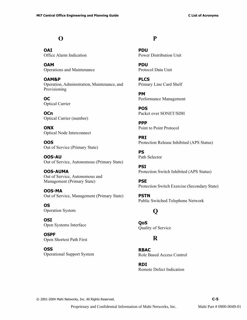
Mi7 Central Office Engineering and Planning Guide C List of Acronyms
O
OAIOffice Alarm Indication
OAMOperations and Maintenance
OAM&POperation, Administration, Maintenance, and Provisioning
OCOptical Carrier
OCnOptical Carrier (number)
ONXOptical Node Interconnect
OOSOut of Service (Primary State)
OOS-AUOut of Service, Autonomous (Primary State)
OOS-AUMAOut of Service, Autonomous and Management (Primary State)
OOS-MAOut of Service, Management (Primary State)
OSOperation System
OSIOpen Systems Interface
OSPFOpen Shortest Path First
OSSOperational Support System
P
PDUPower Distribution Unit
PDUProtocol Data Unit
PLCSPrimary Line Card Shelf
PMPerformance Management
POSPacket over SONET/SDH
PPPPoint to Point Protocol
PRIProtection Release Inhibited (APS Status)
PSPath Selector
PSIProtection Switch Inhibited (APS Status)
PSEProtection Switch Exercise (Secondary State)
PSTNPublic Switched Telephone Network
Q
QoSQuality of Service
R
RBACRole Based Access Control
RDIRemote Defect Indication
© 2001-2004 Mahi Networks, Inc. All Rights Reserved. C-5
Proprietary and Confidential Information of Mahi Networks, Inc. Mahi Part # 0900-0049-01
C List of Acronyms Mi7 Central Office Engineering and Planning Guide
RFIRemote Fault Indication
RMSRemovable Media Storage
RTURemote Test Unit
S
SAService Affecting
SDCCSection Data Communication Channel
SDHSynchronous Digital Hierarchy
SDXSONET/SDH Digital Cross Connect
SFPSmall Form Pluggable
SGEOSupporting Entity OOS (Secondary State)
SNMPSimple Network Management Protocol
SOCSwitch Oscillation Control
SONETSynchronous Optical Network
SPESynchronous Payload Envelope
SRASONET Ring Aggregation
SSHSecure Shell
SSLSecure Socket Layer
STBYStandby (Secondary State)
STMSynchronous Transport Module
STSSynchronous Transport Signal
SYNCSynchronization Module
T
TARPTarget Address Resolution Protocol
TAPTest Access Path
TAUTest Access Unit
TCAThreshold Crossing Alert
TCP/IPTransmission Control Protocol / Internet Protocol
TDMTime Division Multiplexing
TIDTarget Identifier
TL1Transaction Language 1
U
UDPUniversal Datagram Protocol
UPSRUnidirectional Path Switched Ring
C-6 © 2001-2004 Mahi Networks, Inc. All Rights Reserved.
Proprietary and Confidential Information of Mahi Networks, Inc. Mahi Part # 0900-0049-01
Mi7 Central Office Engineering and Planning Guide C List of Acronyms
V
VLANVirtual Local Area Network
VPLSVirtual Private LAN Service
VPNVirtual Private Network
VTVirtual Tributary
VTGVirtual Tributary Group
W
WNWarning (Alarm State)
X
X3FSX3 Switch Fabric Shelf
XCSwitch Matrix Card
XMLExtensible Markup Language
© 2001-2004 Mahi Networks, Inc. All Rights Reserved. C-7
Proprietary and Confidential Information of Mahi Networks, Inc. Mahi Part # 0900-0049-01

C List of Acronyms Mi7 Central Office Engineering and Planning Guide
C-8 © 2001-2004 Mahi Networks, Inc. All Rights Reserved.
Proprietary and Confidential Information of Mahi Networks, Inc. Mahi Part # 0900-0049-01
Index
Port cardsee Fabric Port Card
Aacronyms, list of C-1architecture, specifications A-1audience for guide 1-1
Bbehavior
LED B-1line card LEDs B-5
blank cardsimportance of 4-7
blankscircuit breaker 4-2
Ccards
types of A-8channel plan, ITU grid optics A-12circuit breaker
required ratings 4-3compliance, standards A-2components, hardware specifications A-4connection
line card to port card 3-13contact information
Mahi Networks 1-5conventions
installation 1-1text 1-1
Ddamage
prevention 2-5displays
LED B-1line card LEDs B-5
shelf LEDs B-2documentation
feedback 1-4list of 1-2obtaining 1-4set titles 1-2
drawings, rack face 3-4
EELCS
LED B-4NCC A-3
equipmentspecifications A-4
Expansion Line Card Shelf (ELCS) 3-28
FFabric Port Card B-12
connection to line card 3-13FCC (fabric controller card) B-13Floor Plan
recommendationsconfiguration 1 3-4configuration 2 3-5configuration 3 3-6
front mountPDU 3-21shelf 3-19
GGbE
faceplate LEDs B-9specifications A-13
guideaudience 1-1
guide objectives 1-1guidelines
safety 2-1
© 2001-2004 Mahi Networks, Inc. All Rights Reserved. D-1
Proprietary and Confidential Information of Mahi Networks, Inc. Mahi Part # 0900-0049-01
D Index (H - O) Mi7 Central Office Engineering and Planning Guide
Hhandling
line card 2-6requirements 3-22
handling requirementsextraction procedure 3-23injection procedure 3-22
hardware 3-13specifications A-4
HVACspecifications A-15
Iinstall
general cautions 2-2information 2-2line card 2-6
Installationpreparation 3-26
installationapproach 3-26mechanical descriptions 3-27site preparation 3-26
interfaceoptical specifications A-9
ITU grid optics, channel plan A-12
LLED
displays and behaviors B-1ELCS B-4line card displays and behaviors B-5PLCS B-2shelf displays B-2X3FS B-4
line cardconnection to port card 3-13damage prevention 2-5handling 2-6installing 2-6placement 3-13replacing 2-6storing 2-6transporting 2-8
line cardsFabric Controller B-13
Fabric Port B-12GbE A-13, B-9NCC2 B-11OC-192/STM-64 B-8OC-192/STM-64 C-Band tunable B-8OC-3/12-STM-1/4 B-6OC-3-STM-1 B-5OC-48/STM-16 B-8OC-48/STM-16 (Octal) B-7specifications A-8, A-9XC Switch Matrix B-14
MMahi Networks
contact information 1-5MAT
wiring diagram 4-6mechanical description
racks 3-28mechanical descriptions
shelves 3-28Mechanical Requirements 3-13Mi7
card types A-8overview 3-2specifications A-1
mid-mountshelf 3-20
mountPDU front 3-21shelf front 3-19shelf mid- 3-20
mountingrack options 3-19
NNCC
specifications A-2NCC (network controller card)
specifications A-2Network Controller Card 2 (NCC2) B-11nomenclature
installation 1-1
Oobjectives
D-2 © 2001-2004 Mahi Networks, Inc. All Rights Reserved.
Proprietary and Confidential Information of Mahi Networks, Inc. Mahi Part # 0900-0049-01
Mi7 Central Office Engineering and Planning Guide D Index (P - S)
guide 1-1OC-192, parameters A-11OC-192/STM-64 B-8OC-192/STM-64 C-Band tunable B-8OC-3/12-STM-1/4 B-6OC-3-STM-1 B-5OC-48, parameters A-11OC-48/STM-16 B-8OC-48/STM-16 (Octal) B-7office facility
power recommendations 4-4optic terminations 3-12optical fiber
handling 2-3repairing 2-4using 2-2
optical parameters, OC-48 and OC-192 A-11options
rack mounting 3-19
PPDU
configurationscircuit breaker 4-2
front mount 3-21wiring diagram 4-6
pin numbersDB9 RS-232 3-9RJ-45 3-10
pinoutDB9 RS-232 craft terminal 3-11DB9 RS-232 management 3-9RJ-45 craft Ethernet 3-11RJ-45 management Ethernet 3-10
PLCSLED B-2NCC A-3
power 2-4input specifications A-15office facility recommendations 4-4specification A-1
Power Distribution Unit 3-28PPX
LED specifications B-10preparation 3-1
installation 3-26parts required (not shipped) 3-25tools and equipment 3-24
Primary Line Card Shelf (PLCS) 3-28
Rrack 3-13
mounting options 3-19rack face drawings 3-4repair information 1-4replace
line card 2-6requirements
building 3-16cable management 3-16electrical 3-17environmental 3-17handling 3-22hardware 3-13mechanical 3-13rack 3-13space 3-17spares storage 3-16special 3-16timing 3-17
return information 1-4revision history II-i
Ssafety guidelines 2-1schedule
shelf cabling 4-3server cards, PPX B-10shelf
Expansion Line Card Shelf (ELCS) 3-28front mount 3-19mechanical descriptions 3-28mid-mount 3-20Power Distribution Unit 3-28Primary Line Card Shelf (PLCS) 3-28X3 Fabric Shelf (X3FS) 3-28
shelf, LED displays B-2shelves
LED displays B-2shipping pallets 3-16slot assignment scheme
Octal OC-48 3-16specifications
(GbE) line cards A-13architecture A-1
© 2001-2004 Mahi Networks, Inc. All Rights Reserved. D-3
Proprietary and Confidential Information of Mahi Networks, Inc. Mahi Part # 0900-0049-01
D Index (T - X) Mi7 Central Office Engineering and Planning Guide
environmental A-15equipment A-4HVAC A-15interface port A-3line cards A-8, A-9Mi7 A-1network controller A-2optical interfaces A-9supported standards A-4system A-1system architecture A-1system management A-4
standards compliance A-2static electricity 2-5storage
line card 2-6system
facility density A-3specifications A-1
TTechnical Assistance Center (TAC) 1-4technical support 1-4Telcordia, environmental specifications A-15terminations
cables and wires 3-8optic 3-12
text conventions 1-1Thomas and Betts
tools 3-24tools and equipment
crimping tools 3-24trademarks I-iitransporting
line cards 2-8
Wwarranty I-iiwire
cables and terminations 3-8wiring
cable routing 4-5MAT and PDU diagrams 4-6MAT layouts 4-5
XX3 Fabric Shelf (X3FS) 3-28
LED B-4XC Switch Matrix Card B-14
D-4 © 2001-2004 Mahi Networks, Inc. All Rights Reserved.
Proprietary and Confidential Information of Mahi Networks, Inc. Mahi Part # 0900-0049-01