mfu-15e / mfu-15s mobilefiltration unit€¦ · mfu-15e / mfu-15s mobilefiltration unit operating...
TRANSCRIPT
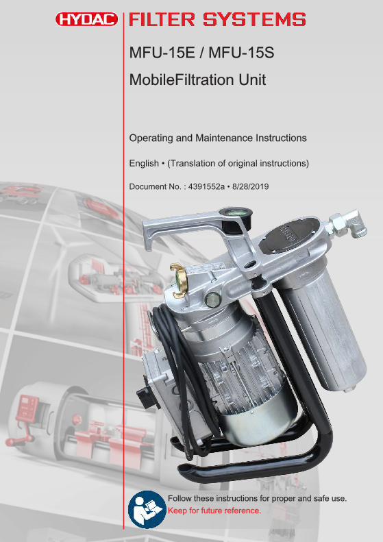
MFU-15E / MFU-15SMobileFiltration Unit
Operating and Maintenance Instructions
English • (Translation of original instructions)
Document No. : 4391552a • 8/28/2019
Follow these instructions for proper and safe use.Keep for future reference.
Table of Contents HYDAC FILTER SYSTEMS GMBH
ii BeWa MFU-15E_S 4391552a en-us lq
Table of Contents
1 General ..................................................................................................................... 5
1.1 Imprint .............................................................................................................. 5
1.2 Documentation Representative........................................................................ 5
1.3 Purpose of this manual .................................................................................... 6
1.4 Target group of the manual.............................................................................. 6
1.5 Illustrations in the manual ................................................................................ 71.5.1 Illustration on the title page.................................................................. 71.5.2 Representation of requirements .......................................................... 81.5.3 Representation of procedural instructions ........................................... 81.5.4 Representation of intermediate results/results .................................... 91.5.5 Representation of warning/general safety information ...................... 101.5.6 Signal words and their meaning in the general safety information .... 11
1.6 Hazard symbols / pictograms......................................................................... 12
1.7 Supplementary symbols................................................................................. 14
1.8 Exclusion of liability/warranty ......................................................................... 14
1.9 Notes on copyright ......................................................................................... 15
1.10 Validity of this manual .................................................................................... 15
2 General safety information ...................................................................................... 16
2.1 Observe regulatory information...................................................................... 19
2.2 Wear suitable clothing.................................................................................... 20
2.3 Stoppage in an emergency (EMERGENCY STOP)....................................... 20
2.4 Fire-fighting / extinguishing a fire ................................................................... 20
3 Overview of the filtration unit................................................................................... 22
3.1 MFU-15S9-… for higher viscosity / with signal cable..................................... 22
3.2 Proper/designated use ................................................................................... 23
3.3 Improper Use or Use Deviating from Intended Use ....................................... 24
3.4 Checking the scope of delivery ...................................................................... 25
3.5 Decoding the type label.................................................................................. 263.5.1 Model code ........................................................................................ 27
HYDAC FILTER SYSTEMS GMBH Table of Contents
BeWa MFU-15E_S 4391552a en-us lq iii
3.6 Technical Data ............................................................................................... 28
3.7 Drawings / dimensions / hydraulic diagram.................................................... 303.7.1 MFU-15E9-... Economy ..................................................................... 30
3.7.1.1 MFU-15E9 - Dimensions / hydraulic diagram........................... 313.7.2 MFU-15S9-... Standard ..................................................................... 34
3.7.2.1 MFU-15S9 - Dimensions / hydraulic diagram........................... 353.8 Operating elements on the filter unit .............................................................. 37
3.9 Filter unit working principle............................................................................. 39
4 Transporting/storing the filter unit............................................................................ 41
4.1 Storing the filter unit with hoses including lances........................................... 42
5 Setting up / assembly / integration of the filter unit ................................................. 43
5.1 Increasing the stability / adjusting the feet ..................................................... 43
5.2 Avoiding siphoning ......................................................................................... 47
5.3 Avoiding the mixing of oils - Emptying the filter unit....................................... 48
5.4 Making the electrical connections .................................................................. 495.4.1 Connecting filter units with 120/230 V AC or 12/24 V DC, single phase
........................................................................................................... 495.4.2 Connecting filter units with 400 V AC, 3 phase ................................. 51
5.5 Connecting the signal cable (only MFU-15S9-...) .......................................... 52
5.6 Connecting pneumatically (Option - Compressed air motor) ......................... 54
5.7 Connecting the suction/pressure port ............................................................ 55
5.8 Attaching / connecting the suction / pressure hoses (Accessories) ............... 57
5.9 Commissioning............................................................................................... 58
6 Operation ................................................................................................................ 60
6.1 Observe the optical clogging indicator ........................................................... 60
6.2 Selecting operating modes............................................................................. 616.2.1 Circulation pumping with filtration / filtration with dewatering ............ 616.2.2 Circulation pumping without filtration................................................. 62
6.3 Operation with pump nozzle (optional)........................................................... 63
6.4 Operation with counter (optional) ................................................................... 63
Table of Contents HYDAC FILTER SYSTEMS GMBH
iv BeWa MFU-15E_S 4391552a en-us lq
7 Rectifying errors ...................................................................................................... 64
8 Performing maintenance ......................................................................................... 67
8.1 Maintenance table.......................................................................................... 68
8.2 Changing the filter element ............................................................................ 69
8.3 Removing/installing the quick coupling .......................................................... 76
8.4 Removing/installing the protective screen...................................................... 788.4.1 Removing/installing the push-in protective screen ............................ 808.4.2 Removing/installing the push-in protective screen ............................ 82
8.5 Checking/cleaning the protective screen ....................................................... 84
9 Removing / Disposal ............................................................................................... 86
Appendix ................................................................................................................. 87
Finding a Customer Service team.................................................................. 87
Finding spare parts / accessories .................................................................. 88Finding the filter elements ................................................................. 90Accessories list .................................................................................. 91
Glossary .................................................................................................................. 95
Index ....................................................................................................................... 96
HYDAC FILTER SYSTEMS GMBH General | 1
BeWa MFU-15E_S 4391552a en-us lq 5 / 100
1 GeneralIn this chapter, you will find helpful notes on handling these in-structions.
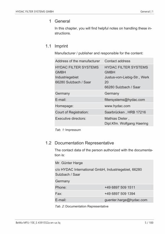
1.1 ImprintManufacturer / publisher and responsible for the content:
Address of the manufacturer Contact address
HYDAC FILTER SYSTEMSGMBH Industriegebiet 66280 Sulzbach / Saar
HYDAC FILTER SYSTEMSGMBH Justus-von-Liebig-Str., Werk20 66280 Sulzbach / Saar
Germany Germany
E-mail: [email protected]
Homepage: www.hydac.com
Court of Registration: Saarbrücken , HRB 17216
Executive directors: Mathias Dieter ,Dipl.Kfm. Wolfgang Haering
Tab. 1: Impressum
1.2 Documentation RepresentativeThe contact data of the person authorized with the documenta-tion is:
Mr. Günter Harge
c/o HYDAC International GmbH, Industriegebiet, 66280Sulzbach / Saar
Germany
Phone: +49 6897 509 1511
Fax: +49 6897 509 1394
E-mail: [email protected]
Tab. 2: Documentation Representative
1 | General HYDAC FILTER SYSTEMS GMBH
6 / 100 BeWa MFU-15E_S 4391552a en-us lq
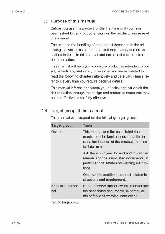
1.3 Purpose of this manualBefore you use this product for the first time or if you havebeen asked to carry out other work on the product, please readthis manual.
The use and the handling of the product described in the fol-lowing, as well as its use, are not self-explanatory and are de-scribed in detail in this manual and the associated technicaldocumentation.
This manual will help you to use the product as intended, prop-erly, effectively, and safely. Therefore, you are requested toread the following chapters attentively and carefully. Please re-fer to it every time you require decisive details.
This manual informs and warns you of risks, against which therisk reduction through the design and protective measures maynot be effective or not fully effective.
1.4 Target group of the manualThis manual was created for the following target group.
Target group Tasks
Owner This manual and the associated docu-ments must be kept accessible at the in-stallation location of the product and alsofor later use.
Ask the employees to read and follow themanual and the associated documents, inparticular, the safety and warning instruc-tions.
Observe the additional product-related in-structions and requirements.
Specialist person-nel
Read, observe and follow this manual andthe associated documents, in particular,the safety and warning instructions.
Tab. 3: Target group
HYDAC FILTER SYSTEMS GMBH General | 1
BeWa MFU-15E_S 4391552a en-us lq 7 / 100
1.5 Illustrations in the manualYou will find illustrations in this manual. You can find details re-garding these in the following chapters.
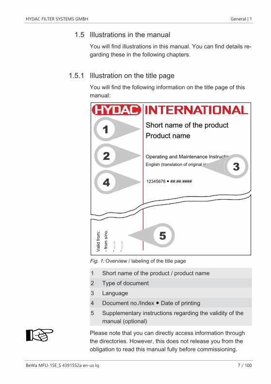
1.5.1 Illustration on the title pageYou will find the following information on the title page of thismanual:
Short name of the productProduct name
Operating and Maintenance Instructions
12345678 ● ##.##.####
English (translation of original instructions)
Valid
from
:- f
rom
s/n
o.- .
.. ...
- ...
...
1
5
2
43
Fig. 1: Overview / labeling of the title page
1 Short name of the product / product name2 Type of document3 Language4 Document no./Index ● Date of printing5 Supplementary instructions regarding the validity of the
manual (optional)
Please note that you can directly access information throughthe directories. However, this does not release you from theobligation to read this manual fully before commissioning.
1 | General HYDAC FILTER SYSTEMS GMBH
8 / 100 BeWa MFU-15E_S 4391552a en-us lq
The document no. with the index (4) is meant for identifyingand reordering the manual. The index is incremented everytime the manual is revised or changed.
The manual contains a table of contents, a list of tables andfigures, an index and a glossary.
1.5.2 Representation of requirementsThese are absolutely required for carrying out a work activityon the product and are marked with a check mark and are inbold in the text.
An example for the representation of requirements:
ü he product is assembled and connected.
ü The product is switched off.
1. Switch the product on.
1.5.3 Representation of procedural instructionsIn the case of procedural instructions, there are the two follow-ing representations:
Procedural instructions with a fixed sequence
Procedural instructions, whose sequence must be compliedwith without fail are listed with sequential numbering (1., 2., 3.,etc.).
An example for procedural instructions with a fixed sequence:
1. Remove the transport securing device.
2. First fill the product.
3. Switch the product on.
Procedural instructions with a random sequence
Procedural instructions that have a random sequence arelisted as bullet points (-).
HYDAC FILTER SYSTEMS GMBH General | 1
BeWa MFU-15E_S 4391552a en-us lq 9 / 100
An example of a procedural instruction with a random se-quence:
– Clean the display.
– Rinse the product.
1.5.4 Representation of intermediate results/resultsIn the case of some activities, it is necessary to carry out worksteps with intermediate results and end results.
Intermediate results are the consequence of activities; they aremarked with an indented arrow.
End results represent the end of an activity and are repre-sented with a flag.
An example for a procedural instruction with intermediate re-sult and final result:
1. Switch the product on.
ð The display lights up.
2. Press the button.
O The product is now ready for use.
1 | General HYDAC FILTER SYSTEMS GMBH
10 / 100 BeWa MFU-15E_S 4391552a en-us lq
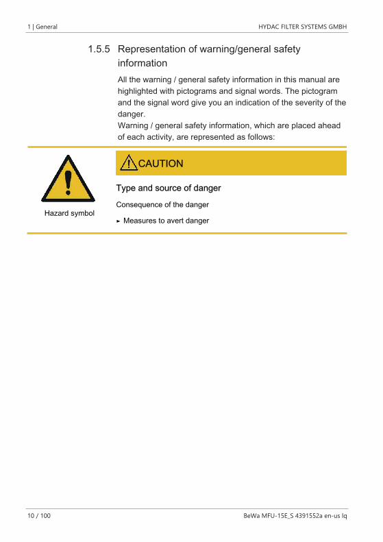
1.5.5 Representation of warning/general safetyinformationAll the warning / general safety information in this manual arehighlighted with pictograms and signal words. The pictogramand the signal word give you an indication of the severity of thedanger.Warning / general safety information, which are placed aheadof each activity, are represented as follows:
CAUTION
Type and source of danger
Hazard symbolConsequence of the danger
Measures to avert danger►
HYDAC FILTER SYSTEMS GMBH General | 1
BeWa MFU-15E_S 4391552a en-us lq 11 / 100
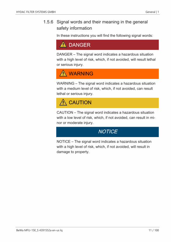
1.5.6 Signal words and their meaning in the generalsafety informationIn these instructions you will find the following signal words:
DANGERDANGER – The signal word indicates a hazardous situationwith a high level of risk, which, if not avoided, will result lethalor serious injury.
WARNING
WARNING – The signal word indicates a hazardous situationwith a medium level of risk, which, if not avoided, can resultlethal or serious injury.
CAUTION
CAUTION – The signal word indicates a hazardous situationwith a low level of risk, which, if not avoided, can result in mi-nor or moderate injury.
NOTICE
NOTICE – The signal word indicates a hazardous situationwith a high level of risk, which, if not avoided, will result indamage to property.
1 | General HYDAC FILTER SYSTEMS GMBH
12 / 100 BeWa MFU-15E_S 4391552a en-us lq
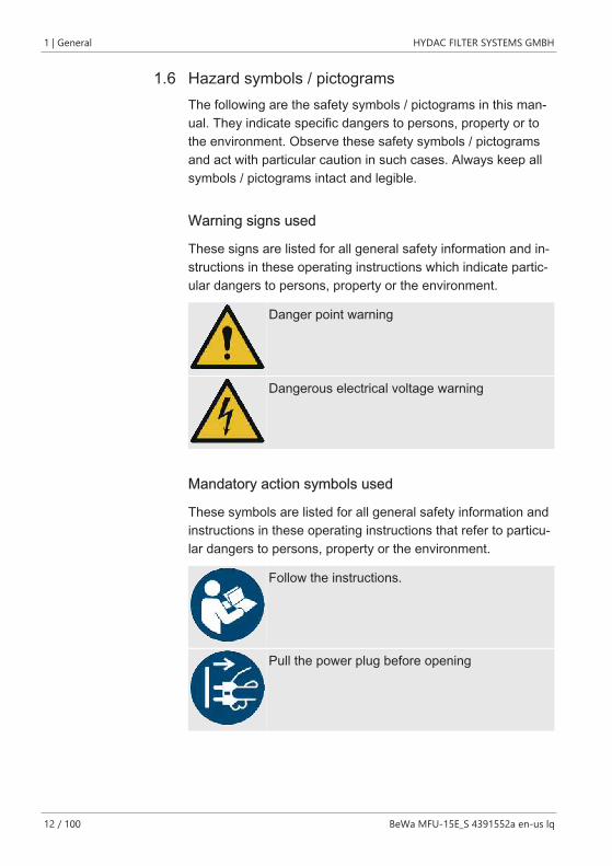
1.6 Hazard symbols / pictogramsThe following are the safety symbols / pictograms in this man-ual. They indicate specific dangers to persons, property or tothe environment. Observe these safety symbols / pictogramsand act with particular caution in such cases. Always keep allsymbols / pictograms intact and legible.
Warning signs used
These signs are listed for all general safety information and in-structions in these operating instructions which indicate partic-ular dangers to persons, property or the environment.
Danger point warning
Dangerous electrical voltage warning
Mandatory action symbols used
These symbols are listed for all general safety information andinstructions in these operating instructions that refer to particu-lar dangers to persons, property or the environment.
Follow the instructions.
Pull the power plug before opening
HYDAC FILTER SYSTEMS GMBH General | 1
BeWa MFU-15E_S 4391552a en-us lq 13 / 100
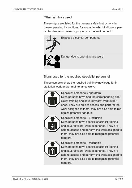
Other symbols used
These signs are listed for the general safety instructions inthese operating instructions, for example, which indicate a par-ticular danger to persons, property or the environment.
Exposed electrical components
Danger due to operating pressure
Signs used for the required specialist personnel
These symbols show the required training/knowledge for in-stallation work and/or maintenance work.
Specialist personnel / operatorsSuch persons have had the corresponding spe-cialist training and several years' work experi-ence. They are able to assess and perform thework assigned to them, they are also able to rec-ognize potential dangers.
Specialist personnel - ElectricianSuch persons have specific specialist trainingand several years' work experience. They areable to assess and perform the work assigned tothem, they are also able to recognize potentialdangers.
Specialist personnel - MechanicSuch persons have specific specialist trainingand several years' work experience. They areable to assess and perform the work assigned tothem, they are also able to recognize potentialdangers.
1 | General HYDAC FILTER SYSTEMS GMBH
14 / 100 BeWa MFU-15E_S 4391552a en-us lq
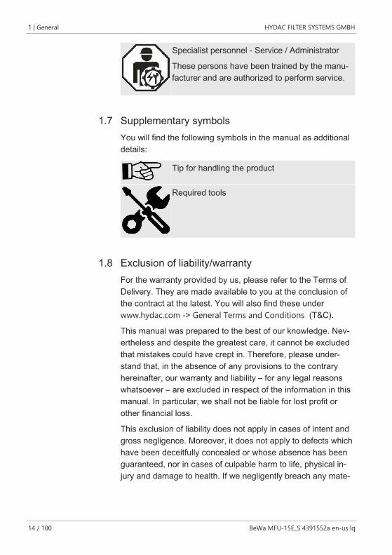
Specialist personnel - Service / Administrator
These persons have been trained by the manu-facturer and are authorized to perform service.
1.7 Supplementary symbolsYou will find the following symbols in the manual as additionaldetails:
Tip for handling the product
Required tools
1.8 Exclusion of liability/warrantyFor the warranty provided by us, please refer to the Terms ofDelivery. They are made available to you at the conclusion ofthe contract at the latest. You will also find these underwww.hydac.com -> General Terms and Conditions (T&C).
This manual was prepared to the best of our knowledge. Nev-ertheless and despite the greatest care, it cannot be excludedthat mistakes could have crept in. Therefore, please under-stand that, in the absence of any provisions to the contraryhereinafter, our warranty and liability – for any legal reasonswhatsoever – are excluded in respect of the information in thismanual. In particular, we shall not be liable for lost profit orother financial loss.
This exclusion of liability does not apply in cases of intent andgross negligence. Moreover, it does not apply to defects whichhave been deceitfully concealed or whose absence has beenguaranteed, nor in cases of culpable harm to life, physical in-jury and damage to health. If we negligently breach any mate-
HYDAC FILTER SYSTEMS GMBH General | 1
BeWa MFU-15E_S 4391552a en-us lq 15 / 100
rial contractual obligation, our liability shall be limited to fore-seeable damage. Claims due to the Product Liability shall re-main unaffected.
1.9 Notes on copyrightAll copyrights for this manual lies with the manufacturer. Nopart of this manual may be reproduced in any form or pro-cessed, duplicated or distributed using electronic systems with-out the written consent of the manufacturer. Any infringementsof the above shall be liable to damage compensation.
1.10 Validity of this manualThe diagrams and visualizations in this manual are meant forgeneral illustration purposes. Therefore, representations andfunctional options can deviate from the delivered product.
We reserve the right to changes to the contents of this manualwithout prior notice.
2 | General safety information HYDAC FILTER SYSTEMS GMBH
16 / 100 BeWa MFU-15E_S 4391552a en-us lq
2 General safety information
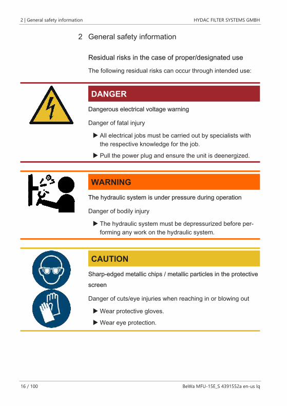
Residual risks in the case of proper/designated use
The following residual risks can occur through intended use:
DANGERDangerous electrical voltage warning
Danger of fatal injury
u All electrical jobs must be carried out by specialists withthe respective knowledge for the job.
u Pull the power plug and ensure the unit is deenergized.
WARNINGThe hydraulic system is under pressure during operation
Danger of bodily injury
u The hydraulic system must be depressurized before per-forming any work on the hydraulic system.
CAUTIONSharp-edged metallic chips / metallic particles in the protectivescreen
Danger of cuts/eye injuries when reaching in or blowing out
u Wear protective gloves.
u Wear eye protection.
HYDAC FILTER SYSTEMS GMBH General safety information | 2
BeWa MFU-15E_S 4391552a en-us lq 17 / 100
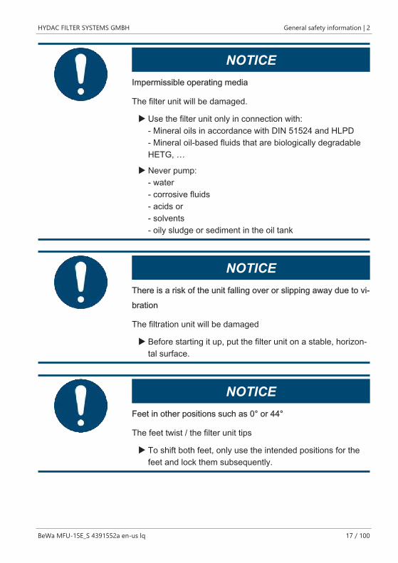
NOTICEImpermissible operating media
The filter unit will be damaged.
u Use the filter unit only in connection with:- Mineral oils in accordance with DIN 51524 and HLPD- Mineral oil-based fluids that are biologically degradableHETG, …
u Never pump:- water- corrosive fluids- acids or- solvents- oily sludge or sediment in the oil tank
NOTICEThere is a risk of the unit falling over or slipping away due to vi-bration
The filtration unit will be damaged
u Before starting it up, put the filter unit on a stable, horizon-tal surface.
NOTICEFeet in other positions such as 0° or 44°
The feet twist / the filter unit tips
u To shift both feet, only use the intended positions for thefeet and lock them subsequently.
2 | General safety information HYDAC FILTER SYSTEMS GMBH
18 / 100 BeWa MFU-15E_S 4391552a en-us lq
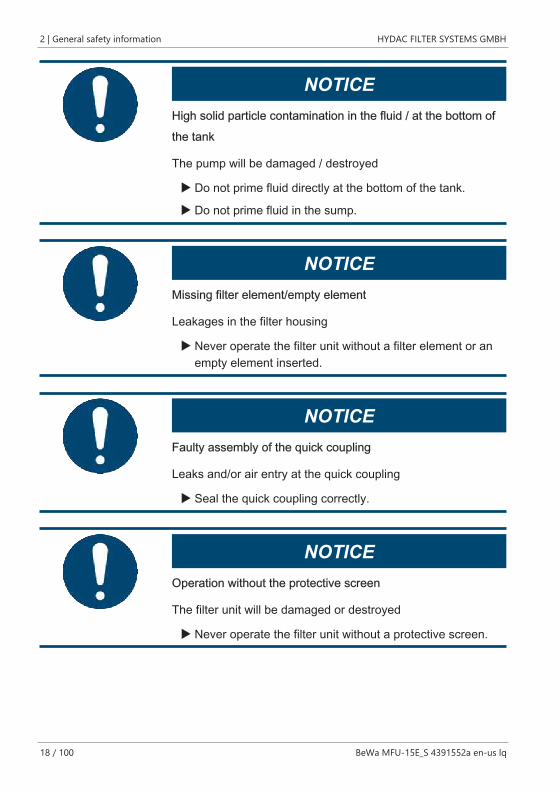
NOTICEHigh solid particle contamination in the fluid / at the bottom ofthe tank
The pump will be damaged / destroyed
u Do not prime fluid directly at the bottom of the tank.
u Do not prime fluid in the sump.
NOTICEMissing filter element/empty element
Leakages in the filter housing
u Never operate the filter unit without a filter element or anempty element inserted.
NOTICEFaulty assembly of the quick coupling
Leaks and/or air entry at the quick coupling
u Seal the quick coupling correctly.
NOTICEOperation without the protective screen
The filter unit will be damaged or destroyed
u Never operate the filter unit without a protective screen.
HYDAC FILTER SYSTEMS GMBH General safety information | 2
BeWa MFU-15E_S 4391552a en-us lq 19 / 100
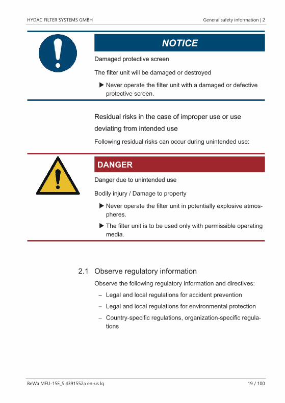
NOTICEDamaged protective screen
The filter unit will be damaged or destroyed
u Never operate the filter unit with a damaged or defectiveprotective screen.
Residual risks in the case of improper use or usedeviating from intended use
Following residual risks can occur during unintended use:
DANGERDanger due to unintended use
Bodily injury / Damage to property
u Never operate the filter unit in potentially explosive atmos-pheres.
u The filter unit is to be used only with permissible operatingmedia.
2.1 Observe regulatory informationObserve the following regulatory information and directives:
– Legal and local regulations for accident prevention
– Legal and local regulations for environmental protection
– Country-specific regulations, organization-specific regula-tions
2 | General safety information HYDAC FILTER SYSTEMS GMBH
20 / 100 BeWa MFU-15E_S 4391552a en-us lq
2.2 Wear suitable clothingLoose-fitting clothing increases the danger of being caught orbeing drawn in on rotating parts, and the risk of getting caughton protruding parts. You can be severely injured or killed inthese cases.
– Wear closely fitting clothing.
– Do not wear any rings, chains or any other jewelry.
– Wear a hair net if you have long hair.
– Wear work safety shoes.
2.3 Stoppage in an emergency (EMERGENCY STOP)Disconnect the product from all sources of energy in an emer-gency.
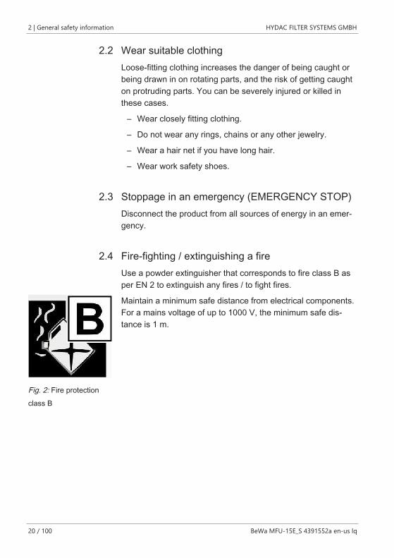
2.4 Fire-fighting / extinguishing a fireUse a powder extinguisher that corresponds to fire class B asper EN 2 to extinguish any fires / to fight fires.
Fig. 2: Fire protectionclass B
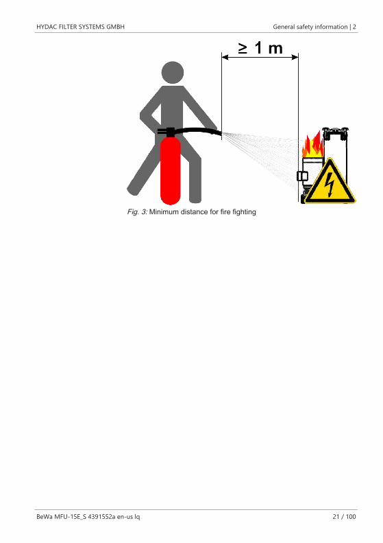
Maintain a minimum safe distance from electrical components.For a mains voltage of up to 1000 V, the minimum safe dis-tance is 1 m.
HYDAC FILTER SYSTEMS GMBH General safety information | 2
BeWa MFU-15E_S 4391552a en-us lq 21 / 100
Fig. 3: Minimum distance for fire fighting
3 | Overview of the filtration unit HYDAC FILTER SYSTEMS GMBH
22 / 100 BeWa MFU-15E_S 4391552a en-us lq
3 Overview of the filtration unitThe MFU is a mobile filter unit and is especially suitable for fill-ing hydraulic units, for flushing small hydraulic units, e.g. whencommissioning, for offline filtration of mineral oil in hydraulicunits and for recirculation with / without simultaneous filtration.
The filter unit has a integrated dry-running protection of thevane pump of up to 60 hours. Dry-running protection is en-sured by a return line leading from the filter housing back tothe vane pump. Pre-fill the filter element to activate the dry-running protection. For details, see Changing the filter element[} 69].
3.1 MFU-15S9-… for higher viscosity / with signalcableThe filter unit MFU-15S9-... is designed for a higher viscosity.The electric motor has a higher driver power and the filter unitis equipped with a signal cable 10 m (2 x 0.5 mm²) with 5-polecoupling (pins) of type AMP T 3360 001. For details, see Con-necting the signal cable (only MFU-15S9-...) [} 52]
HYDAC FILTER SYSTEMS GMBH Overview of the filtration unit | 3
BeWa MFU-15E_S 4391552a en-us lq 23 / 100
3.2 Proper/designated useUse the filter unit only for the application described in the fol-lowing.
The filter unit MFU is a service unit for filling hydraulic systems,flushing small hydraulic systems, cleaning in the bypass flowand recirculation with / without simultaneous filtration, depend-ing on the filter cartridge.
Intended use of the product also extends to the following:
– Observing all instructions in the instruction manual.
– Performing inspection and maintenance work.
NOTICEImpermissible operating media
The filter unit will be damaged.
u Use the filter unit only in connection with:- Mineral oils in accordance with DIN 51524 and HLPD- Mineral oil-based fluids that are biologically degradableHETG, …
u Never pump:- water- corrosive fluids- acids or- solvents- oily sludge or sediment in the oil tank
Claims for defects or liability, regardless of the legal founda-tion, do not apply with incorrect or improper installation, com-missioning, usage, handling, storage, maintenance, repair, useof unsuitable components or other circumstances for which themanufacturer is not responsible.
The manufacturer assumes no responsibility for determiningthe interfaces for installation in a system or the installation, useor functionality of the product in this system.
3 | Overview of the filtration unit HYDAC FILTER SYSTEMS GMBH
24 / 100 BeWa MFU-15E_S 4391552a en-us lq
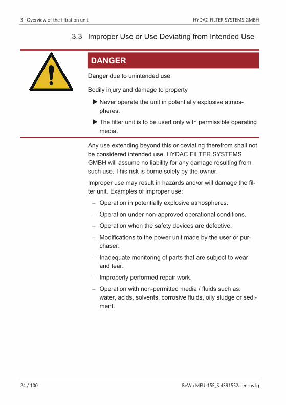
3.3 Improper Use or Use Deviating from Intended Use
DANGERDanger due to unintended use
Bodily injury and damage to property
u Never operate the unit in potentially explosive atmos-pheres.
u The filter unit is to be used only with permissible operatingmedia.
Any use extending beyond this or deviating therefrom shall notbe considered intended use. HYDAC FILTER SYSTEMSGMBH will assume no liability for any damage resulting fromsuch use. This risk is borne solely by the owner.
Improper use may result in hazards and/or will damage the fil-ter unit. Examples of improper use:
– Operation in potentially explosive atmospheres.
– Operation under non-approved operational conditions.
– Operation when the safety devices are defective.
– Modifications to the power unit made by the user or pur-chaser.
– Inadequate monitoring of parts that are subject to wearand tear.
– Improperly performed repair work.
– Operation with non-permitted media / fluids such as:water, acids, solvents, corrosive fluids, oily sludge or sedi-ment.
HYDAC FILTER SYSTEMS GMBH Overview of the filtration unit | 3
BeWa MFU-15E_S 4391552a en-us lq 25 / 100
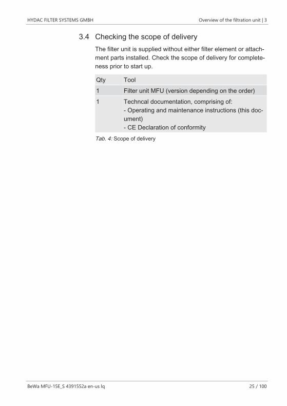
3.4 Checking the scope of deliveryThe filter unit is supplied without either filter element or attach-ment parts installed. Check the scope of delivery for complete-ness prior to start up.
Qty Tool
1 Filter unit MFU (version depending on the order)
1 Techncal documentation, comprising of:- Operating and maintenance instructions (this doc-ument)- CE Declaration of conformity
Tab. 4: Scope of delivery
3 | Overview of the filtration unit HYDAC FILTER SYSTEMS GMBH
26 / 100 BeWa MFU-15E_S 4391552a en-us lq
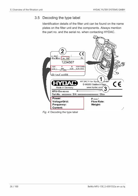
3.5 Decoding the type labelIdentification details of the filter unit can be found on the nameplates on the filter unit and the components. Always mentionthe part no. and the serial no. when contacting HYDAC.
Fig. 4: Decoding the type label
HYDAC FILTER SYSTEMS GMBH Overview of the filtration unit | 3
BeWa MFU-15E_S 4391552a en-us lq 27 / 100
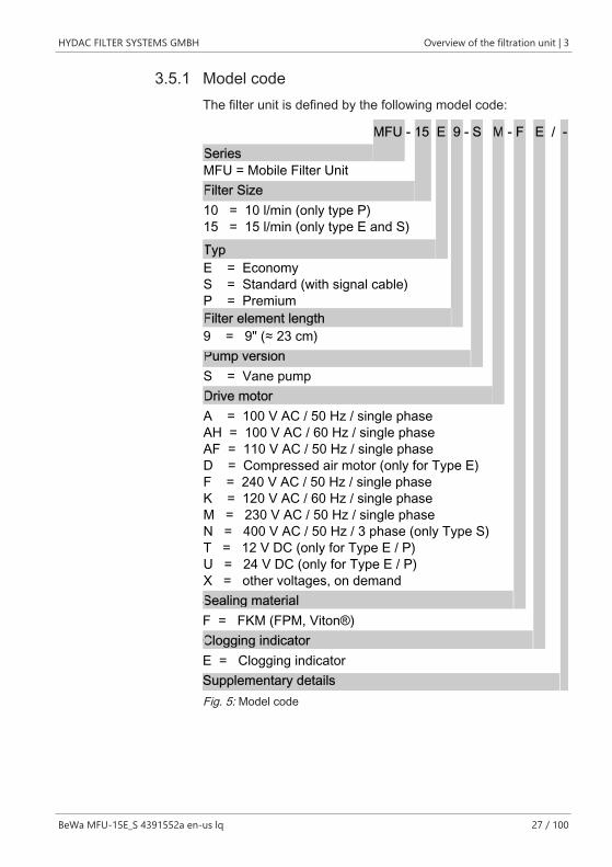
3.5.1 Model codeThe filter unit is defined by the following model code:
Series
Typ
Filter Size
MFU - 15 E 9 - S M - F E / -
Sealing material
Drive motor
Clogging indicator
MFU = Mobile Filter Unit
10 = 10 l/min (only type P)15 = 15 l/min (only type E and S)
E = Economy
F = FKM (FPM, Viton®)
Filter element length9 = 9" (≈ 23 cm)Pump versionS = Vane pump
A = 100 V AC / 50 Hz / single phaseAH = 100 V AC / 60 Hz / single phaseAF = 110 V AC / 50 Hz / single phaseD = Compressed air motor (only for Type E)F = 240 V AC / 50 Hz / single phaseK = 120 V AC / 60 Hz / single phaseM = 230 V AC / 50 Hz / single phaseN = 400 V AC / 50 Hz / 3 phase (only Type S)T = 12 V DC (only for Type E / P)U = 24 V DC (only for Type E / P)X = other voltages, on demand
Supplementary detailsE = Clogging indicator
S = Standard (with signal cable)P = Premium
Fig. 5: Model code
3 | Overview of the filtration unit HYDAC FILTER SYSTEMS GMBH
28 / 100 BeWa MFU-15E_S 4391552a en-us lq
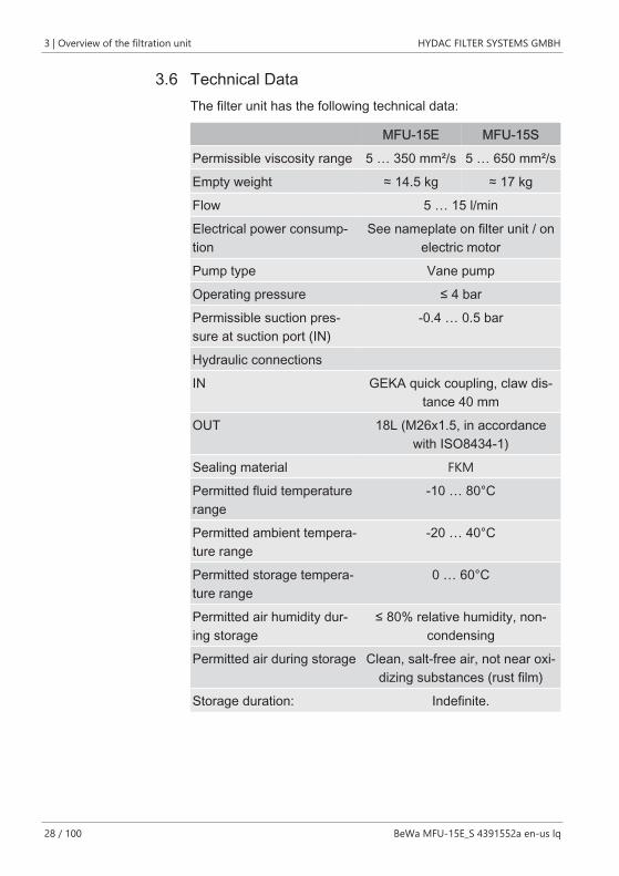
3.6 Technical DataThe filter unit has the following technical data:
MFU-15E MFU-15S
Permissible viscosity range 5 … 350 mm²/s 5 … 650 mm²/s
Empty weight ≈ 14.5 kg ≈ 17 kg
Flow 5 … 15 l/min
Electrical power consump-tion
See nameplate on filter unit / onelectric motor
Pump type Vane pump
Operating pressure ≤ 4 bar
Permissible suction pres-sure at suction port (IN)
-0.4 … 0.5 bar
Hydraulic connections
IN GEKA quick coupling, claw dis-tance 40 mm
OUT 18L (M26x1.5, in accordancewith ISO8434-1)
Sealing material FKM
Permitted fluid temperaturerange
-10 … 80°C
Permitted ambient tempera-ture range
-20 … 40°C
Permitted storage tempera-ture range
0 … 60°C
Permitted air humidity dur-ing storage
≤ 80% relative humidity, non-condensing
Permitted air during storage Clean, salt-free air, not near oxi-dizing substances (rust film)
Storage duration: Indefinite.
HYDAC FILTER SYSTEMS GMBH Overview of the filtration unit | 3
BeWa MFU-15E_S 4391552a en-us lq 29 / 100
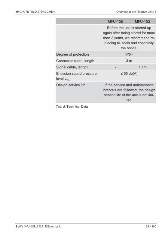
MFU-15E MFU-15S
Before the unit is started upagain after being stored for morethan 2 years, we recommend re-placing all seals and especially
the hoses.
Degree of protection IP54
Connector cable, length 3 m
Signal cable, length - 10 m
Emission sound pressurelevel LPA
≤ 65 db(A)
Design service life If the service and maintenanceintervals are followed, the designservice life of the unit is not lim-
ited.
Tab. 5: Technical Data
3 | Overview of the filtration unit HYDAC FILTER SYSTEMS GMBH
30 / 100 BeWa MFU-15E_S 4391552a en-us lq
3.7 Drawings / dimensions / hydraulic diagramThe drawings/dimensions and hydraulic diagram of the variousproduct variants can be found below. Check the model codeon the name plate of the filter unit.
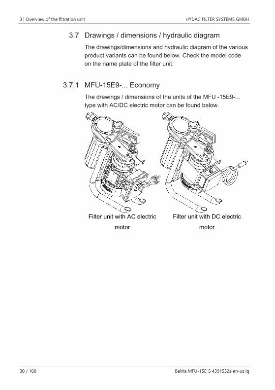
3.7.1 MFU-15E9-... EconomyThe drawings / dimensions of the units of the MFU -15E9-...type with AC/DC electric motor can be found below.
Filter unit with AC electricmotor
Filter unit with DC electricmotor
HYDAC FILTER SYSTEMS GMBH Overview of the filtration unit | 3
BeWa MFU-15E_S 4391552a en-us lq 31 / 100
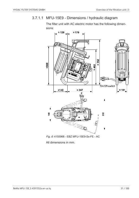
3.7.1.1 MFU-15E9 - Dimensions / hydraulic diagramThe filter unit with AC electric motor has the following dimen-sions:
Fig. 6: 4155968 - EBZ MFU-15E9-Sx-FE - AC
All dimensions in mm.
3 | Overview of the filtration unit HYDAC FILTER SYSTEMS GMBH
32 / 100 BeWa MFU-15E_S 4391552a en-us lq
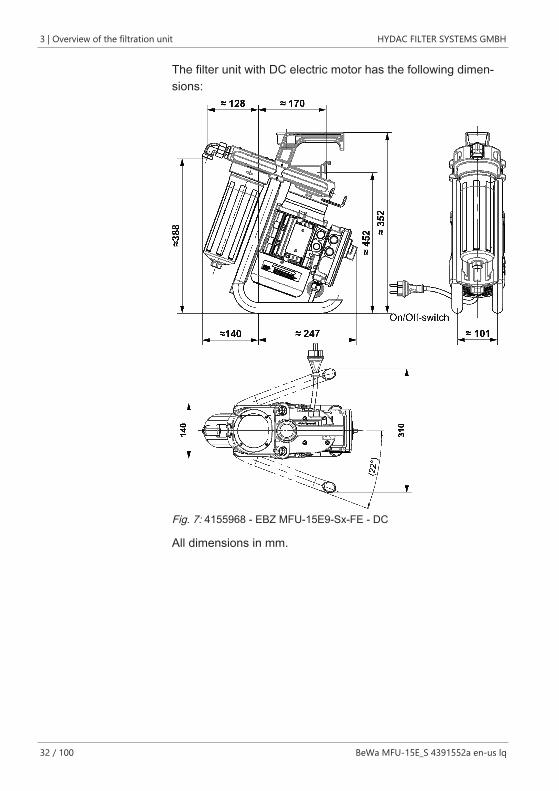
The filter unit with DC electric motor has the following dimen-sions:
Fig. 7: 4155968 - EBZ MFU-15E9-Sx-FE - DC
All dimensions in mm.
HYDAC FILTER SYSTEMS GMBH Overview of the filtration unit | 3
BeWa MFU-15E_S 4391552a en-us lq 33 / 100
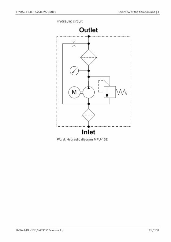
Hydraulic circuit:
Fig. 8: Hydraulic diagram MFU-15E
3 | Overview of the filtration unit HYDAC FILTER SYSTEMS GMBH
34 / 100 BeWa MFU-15E_S 4391552a en-us lq
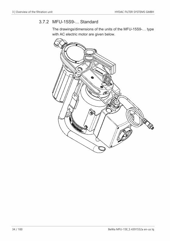
3.7.2 MFU-15S9-... StandardThe drawings/dimensions of the units of the MFU-15S9-… typewith AC electric motor are given below.
HYDAC FILTER SYSTEMS GMBH Overview of the filtration unit | 3
BeWa MFU-15E_S 4391552a en-us lq 35 / 100
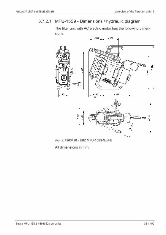
3.7.2.1 MFU-15S9 - Dimensions / hydraulic diagramThe filter unit with AC electric motor has the following dimen-sions:
Fig. 9: 4263428 - EBZ MFU-15S9-Sx-FE
All dimensions in mm.
3 | Overview of the filtration unit HYDAC FILTER SYSTEMS GMBH
36 / 100 BeWa MFU-15E_S 4391552a en-us lq
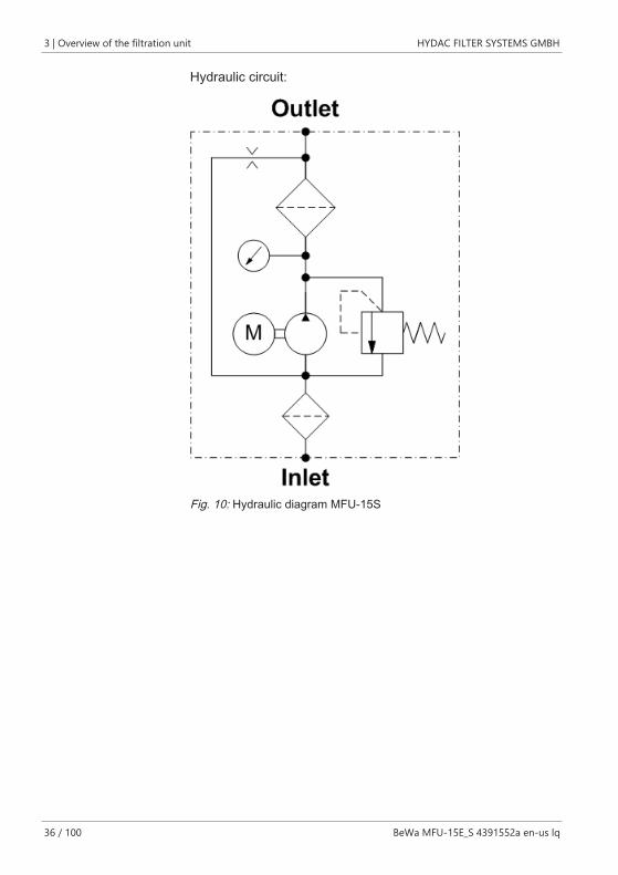
Hydraulic circuit:
Fig. 10: Hydraulic diagram MFU-15S
HYDAC FILTER SYSTEMS GMBH Overview of the filtration unit | 3
BeWa MFU-15E_S 4391552a en-us lq 37 / 100
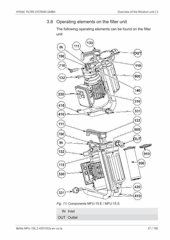
3.8 Operating elements on the filter unitThe following operating elements can be found on the filterunit:
Fig. 11: Components MFU-15 E / MFU-15 S
IN InletOUT Outlet
3 | Overview of the filtration unit HYDAC FILTER SYSTEMS GMBH
38 / 100 BeWa MFU-15E_S 4391552a en-us lq
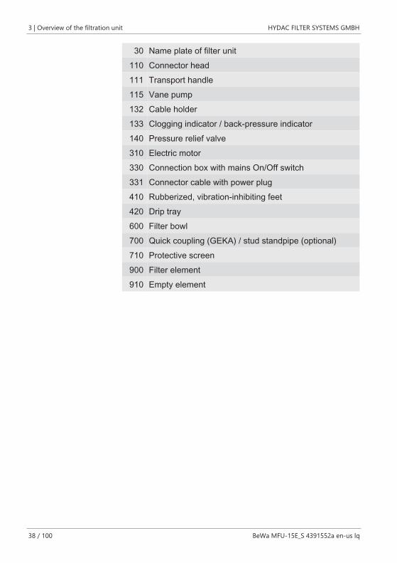
30 Name plate of filter unit110 Connector head111 Transport handle115 Vane pump132 Cable holder133 Clogging indicator / back-pressure indicator140 Pressure relief valve310 Electric motor330 Connection box with mains On/Off switch331 Connector cable with power plug410 Rubberized, vibration-inhibiting feet420 Drip tray600 Filter bowl700 Quick coupling (GEKA) / stud standpipe (optional)710 Protective screen900 Filter element910 Empty element
HYDAC FILTER SYSTEMS GMBH Overview of the filtration unit | 3
BeWa MFU-15E_S 4391552a en-us lq 39 / 100
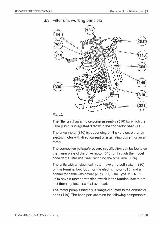
3.9 Filter unit working principle
Fig. 12:
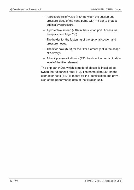
The filter unit has a motor-pump assembly (310) for which thevane pump is integrated directly in the connector head (110).
The drive motor (310) is, depending on the version, either anelectric motor with direct current or alternating current or an airmotor.
The connection voltage/pressure specification can be found onthe name plate of the drive motor (310) or through the modelcode of the filter unit, see Decoding the type label [} 26].
The units with an electrical motor have an on/off switch (330)on the terminal box (330) for the electric motor (310) and aconnector cable with power plug (331). The Type MFU-...Sunits have a motor protection switch in the terminal box to pro-tect them against electrical overload.
The motor pump assembly is flange-mounted to the connectorhead (110). The head part contains the following components:
3 | Overview of the filtration unit HYDAC FILTER SYSTEMS GMBH
40 / 100 BeWa MFU-15E_S 4391552a en-us lq
– A pressure relief valve (140) between the suction andpressure sides of the vane pump with ≈ 4 bar to protectagainst overpressure.
– A protective screen (710) in the suction port. Access viathe quick coupling (700).
– The holder for the fastening of the optional suction andpressure hoses.
– The filter bowl (600) for the filter element (not in the scopeof delivery)
– A back pressure indicator (133) to show the contaminationlevel of the filter element.
The drip pan (420), which is made of plastic, is installed be-tween the rubberized feet (410). The name plate (30) on theconnector head (110) is meant for the identification and provi-sion of the performance data of the filtration unit.
HYDAC FILTER SYSTEMS GMBH Transporting/storing the filter unit | 4
BeWa MFU-15E_S 4391552a en-us lq 41 / 100
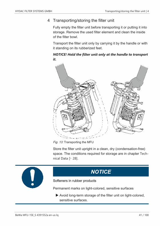
4 Transporting/storing the filter unitFully empty the filter unit before transporting it or putting it intostorage. Remove the used filter element and clean the insideof the filter bowl.
Transport the filter unit only by carrying it by the handle or withit standing on its rubberized feet.
NOTICE! Hold the filter unit only at the handle to transportit.
Fig. 13: Transporting the MFU
Store the filter unit upright in a clean, dry (condensation-free)space. The conditions required for storage are in chapter Tech-nical Data [} 28].
NOTICESofteners in rubber products
Permanent marks on light-colored, sensitive surfaces
u Avoid long-term storage of the filter unit on light-colored,sensitive surfaces.
4 | Transporting/storing the filter unit HYDAC FILTER SYSTEMS GMBH
42 / 100 BeWa MFU-15E_S 4391552a en-us lq
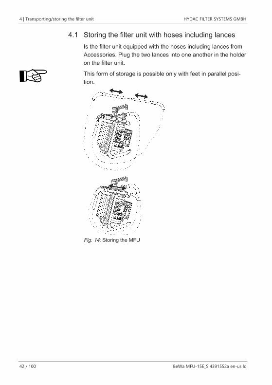
4.1 Storing the filter unit with hoses including lancesIs the filter unit equipped with the hoses including lances fromAccessories. Plug the two lances into one another in the holderon the filter unit.
This form of storage is possible only with feet in parallel posi-tion.
Fig. 14: Storing the MFU
HYDAC FILTER SYSTEMS GMBH Setting up / assembly / integration of the filter unit | 5
BeWa MFU-15E_S 4391552a en-us lq 43 / 100
5 Setting up / assembly / integration of the filter unitObserve the following notices for setting up the unit.
NOTICEThere is a risk of the unit falling over or slipping away due to vi-bration
The filtration unit will be damaged
u Before starting it up, put the filter unit on a stable, horizon-tal surface.
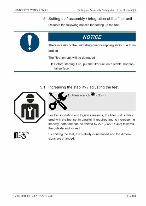
5.1 Increasing the stability / adjusting the feet
1x Allen wrench = 2 mm
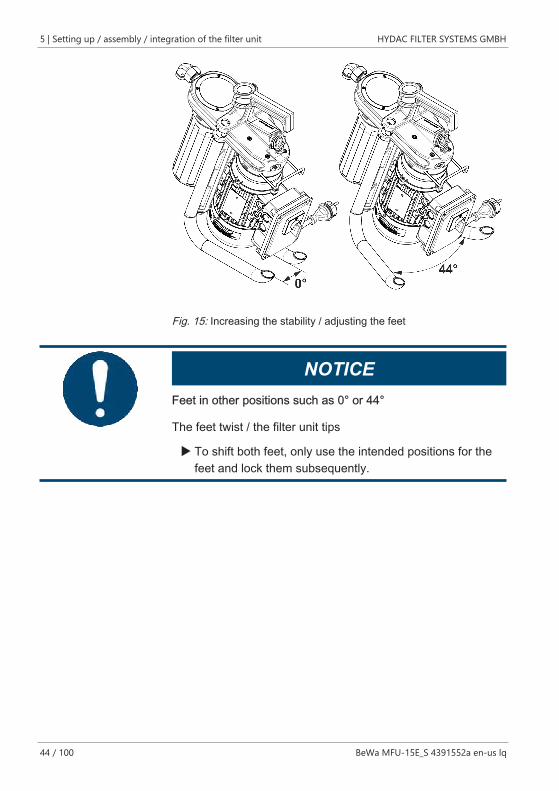
For transportation and logistics reasons, the filter unit is deliv-ered with the feet set in parallel. If required and to increase thestability, both feet can be shifted by 22° (2x22° = 44°) towardsthe outside and locked.
By shifting the feet, the stability is increased and the dimen-sions are changed.
5 | Setting up / assembly / integration of the filter unit HYDAC FILTER SYSTEMS GMBH
44 / 100 BeWa MFU-15E_S 4391552a en-us lq
Fig. 15: Increasing the stability / adjusting the feet
NOTICEFeet in other positions such as 0° or 44°
The feet twist / the filter unit tips
u To shift both feet, only use the intended positions for thefeet and lock them subsequently.
HYDAC FILTER SYSTEMS GMBH Setting up / assembly / integration of the filter unit | 5
BeWa MFU-15E_S 4391552a en-us lq 45 / 100
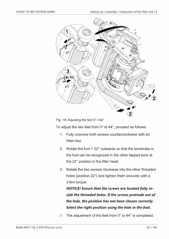
Fig. 16: Adjusting the feet 0°->44°
To adjust the two feet from 0° to 44°, proceed as follows:
1. Fully unscrew both screws counterclockwise with anAllen key.
2. Rotate the foot ≈ 22° outwards so that the boreholes inthe foot can be recognized in the other tapped bore atthe 22° position in the filter head.
3. Rotate the two screws clockwise into the other threadedholes (position 22°) and tighten them securely with a3 Nm torque.NOTICE! Ensure that the screws are located fully in-side the threaded holes. If the screws protrude out ofthe hole, the position has not been chosen correctly.Select the right position using the hole in the foot.
O The adjustment of the feet from 0° to 44° is completed.
5 | Setting up / assembly / integration of the filter unit HYDAC FILTER SYSTEMS GMBH
46 / 100 BeWa MFU-15E_S 4391552a en-us lq
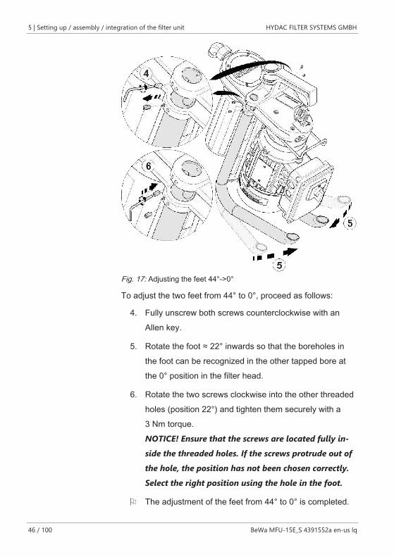
Fig. 17: Adjusting the feet 44°->0°
To adjust the two feet from 44° to 0°, proceed as follows:
4. Fully unscrew both screws counterclockwise with anAllen key.
5. Rotate the foot ≈ 22° inwards so that the boreholes inthe foot can be recognized in the other tapped bore atthe 0° position in the filter head.
6. Rotate the two screws clockwise into the other threadedholes (position 22°) and tighten them securely with a3 Nm torque.NOTICE! Ensure that the screws are located fully in-side the threaded holes. If the screws protrude out ofthe hole, the position has not been chosen correctly.Select the right position using the hole in the foot.
O The adjustment of the feet from 44° to 0° is completed.
HYDAC FILTER SYSTEMS GMBH Setting up / assembly / integration of the filter unit | 5
BeWa MFU-15E_S 4391552a en-us lq 47 / 100
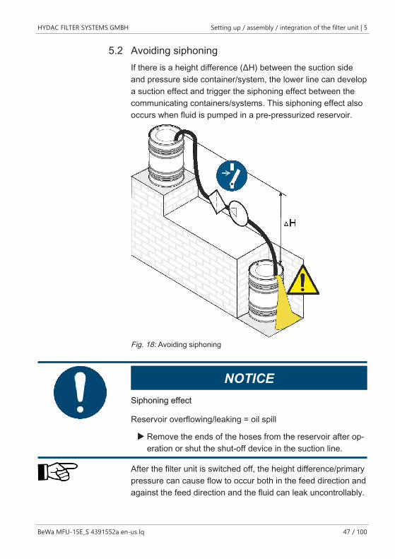
5.2 Avoiding siphoningIf there is a height difference (ΔH) between the suction sideand pressure side container/system, the lower line can developa suction effect and trigger the siphoning effect between thecommunicating containers/systems. This siphoning effect alsooccurs when fluid is pumped in a pre-pressurized reservoir.
Fig. 18: Avoiding siphoning
NOTICESiphoning effect
Reservoir overflowing/leaking = oil spill
u Remove the ends of the hoses from the reservoir after op-eration or shut the shut-off device in the suction line.
After the filter unit is switched off, the height difference/primarypressure can cause flow to occur both in the feed direction andagainst the feed direction and the fluid can leak uncontrollably.
5 | Setting up / assembly / integration of the filter unit HYDAC FILTER SYSTEMS GMBH
48 / 100 BeWa MFU-15E_S 4391552a en-us lq
5.3 Avoiding the mixing of oils - Emptying the filter unitIf you want to use the same oil for operation as in the previousoperation, it is not serious if the oils are mixed.
If you do not know which oil was previously filtered with the fil-ter unit, replace the filter element and empty the filter unit com-pletely in order to prevent mixing with the residual oil in the fil-ter unit.
If different oils are mixed, the oil properties can change as fol-lows:
– Higher risk of cavitation
– More seal wear
– Modified anti-wear properties
– Poorer filtration
– Reduced filter element service lives
– Modified friction characteristics
– Modified response to water
– More deposits due to additive reactions
– More system contamination due to dissolved deposits
– Modified water/air uptake and output properties
– Greater tendency to foam
HYDAC FILTER SYSTEMS GMBH Setting up / assembly / integration of the filter unit | 5
BeWa MFU-15E_S 4391552a en-us lq 49 / 100
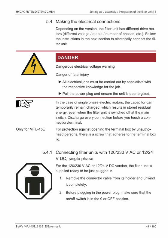
5.4 Making the electrical connectionsDepending on the version, the filter unit has different drive mo-tors (different voltage / output / number of phases, etc.). Followthe instructions in the next section to electrically connect the fil-ter unit.
DANGERDangerous electrical voltage warning
Danger of fatal injury
u All electrical jobs must be carried out by specialists withthe respective knowledge for the job.
u Pull the power plug and ensure the unit is deenergized.
In the case of single phase electric motors, the capacitor cantemporarily remain charged, which results in stored residualenergy, even when the filter unit is switched off at the mainswitch. Discharge every connection before you touch a con-nection/terminal.
Only for MFU-15E For protection against opening the terminal box by unautho-rized persons, there is a screw that adheres to the terminal boxlid.
5.4.1 Connecting filter units with 120/230 V AC or 12/24V DC, single phaseFor the 120/230 V AC or 12/24 V DC version, the filter unit issupplied ready to be just plugged in.
1. Remove the connector cable from its holder and unwindit completely.
2. Before plugging in the power plug, make sure that theon/off switch is in the 0 or OFF position.
5 | Setting up / assembly / integration of the filter unit HYDAC FILTER SYSTEMS GMBH
50 / 100 BeWa MFU-15E_S 4391552a en-us lq
3. Check that the voltage and frequency are correct. Youwill find the filter unit's electrical data on the electric mo-tor's name plate.
4. Plug the power plug into a suitable power outlet.
5. Switch the filter unit on or off using the switch on the mo-tor terminal box.
Depending on the version, the filter unit has thermal protectionin the motor windings and a motor protection switch in thejunction box to protect it from electrical overload.
HYDAC FILTER SYSTEMS GMBH Setting up / assembly / integration of the filter unit | 5
BeWa MFU-15E_S 4391552a en-us lq 51 / 100
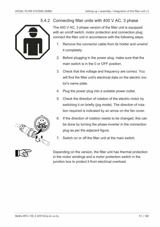
5.4.2 Connecting filter units with 400 V AC, 3 phaseThe 400 V AC, 3 phase version of the filter unit is equippedwith an on/off switch, motor protection and connection plug;connect the filter unit in accordance with the following steps.
1. Remove the connector cable from its holder and unwindit completely.
2. Before plugging in the power plug, make sure that themain switch is in the 0 or OFF position.
3. Check that the voltage and frequency are correct. Youwill find the filter unit's electrical data on the electric mo-tor's name plate.
4. Plug the power plug into a suitable power outlet.
5. Check the direction of rotation of the electric motor byswitching it on briefly (jog mode). The direction of rota-tion required is indicated by an arrow on the fan cover.
6. If the direction of rotation needs to be changed, this canbe done by turning the phase inverter in the connectionplug as per the adjacent figure.
7. Switch on or off the filter unit at the main switch.
Depending on the version, the filter unit has thermal protectionin the motor windings and a motor protection switch in thejunction box to protect it from electrical overload.
5 | Setting up / assembly / integration of the filter unit HYDAC FILTER SYSTEMS GMBH
52 / 100 BeWa MFU-15E_S 4391552a en-us lq
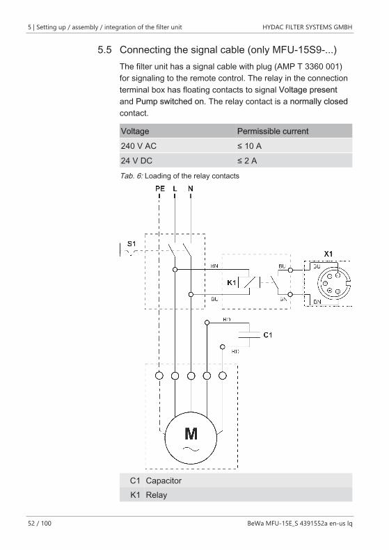
5.5 Connecting the signal cable (only MFU-15S9-...)The filter unit has a signal cable with plug (AMP T 3360 001)for signaling to the remote control. The relay in the connectionterminal box has floating contacts to signal Voltage presentand Pump switched on. The relay contact is a normally closedcontact.
Voltage Permissible current
240 V AC ≤ 10 A
24 V DC ≤ 2 A
Tab. 6: Loading of the relay contacts
C1 CapacitorK1 Relay
HYDAC FILTER SYSTEMS GMBH Setting up / assembly / integration of the filter unit | 5
BeWa MFU-15E_S 4391552a en-us lq 53 / 100
L Phase conductorsM Electric motorW Neutral wire
PE Protective conductorX1 Signal cable with plug connectorBN Brown, code for color identification marking according
to DIN IEC 60757BU Blue, code for color identification marking according to
DIN IEC 60757RD Red, code for color identification marking according to
DIN IEC 60757
5 | Setting up / assembly / integration of the filter unit HYDAC FILTER SYSTEMS GMBH
54 / 100 BeWa MFU-15E_S 4391552a en-us lq
5.6 Connecting pneumatically (Option - Compressedair motor)When using the design with compressed air motor, connect thecompressed air line to the filter unit. To ensure a constant flow,ensure that the compressed air supply is at 5 … 7 bar.
NOTICEPressure connection without shut-off device
The filter unit starts pumping
u Install a shut-off device in the feed-line to switch the filterunit on/off.
HYDAC FILTER SYSTEMS GMBH Setting up / assembly / integration of the filter unit | 5
BeWa MFU-15E_S 4391552a en-us lq 55 / 100
5.7 Connecting the suction/pressure portTake into account the pressure loss when connecting suction/pressure hoses. The suction / pressure hoses from the filterunit Accessories list [} 91] are matched to the filter unit.
The pressure loss in a hydraulic line depends upon:
– Flow
– Kinematic viscosity
– Pipe dimensions
– Fluid density
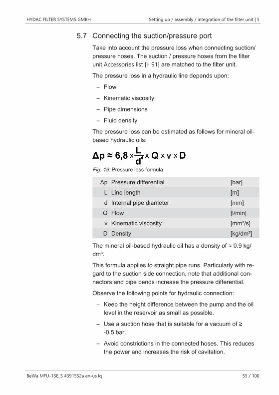
The pressure loss can be estimated as follows for mineral oil-based hydraulic oils:
Fig. 19: Pressure loss formula
Δp Pressure differential [bar]L Line length [m]d Internal pipe diameter [mm]Q Flow [l/min]ν Kinematic viscosity [mm²/s]D Density [kg/dm³]
The mineral oil-based hydraulic oil has a density of ≈ 0.9 kg/dm³.
This formula applies to straight pipe runs. Particularly with re-gard to the suction side connection, note that additional con-nectors and pipe bends increase the pressure differential.
Observe the following points for hydraulic connection:
– Keep the height difference between the pump and the oillevel in the reservoir as small as possible.
– Use a suction hose that is suitable for a vacuum of ≥-0.5 bar.
– Avoid constrictions in the connected hoses. This reducesthe power and increases the risk of cavitation.
5 | Setting up / assembly / integration of the filter unit HYDAC FILTER SYSTEMS GMBH
56 / 100 BeWa MFU-15E_S 4391552a en-us lq
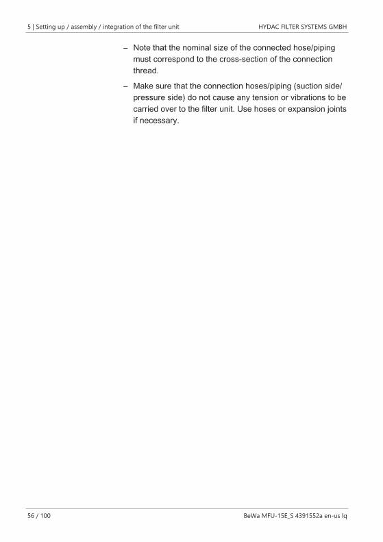
– Note that the nominal size of the connected hose/pipingmust correspond to the cross-section of the connectionthread.
– Make sure that the connection hoses/piping (suction side/pressure side) do not cause any tension or vibrations to becarried over to the filter unit. Use hoses or expansion jointsif necessary.
HYDAC FILTER SYSTEMS GMBH Setting up / assembly / integration of the filter unit | 5
BeWa MFU-15E_S 4391552a en-us lq 57 / 100
5.8 Attaching / connecting the suction / pressure hoses(Accessories)Take into account the pressure loss when connecting suction/pressure hoses. The suction / pressure hoses from the filterunit Accessories list [} 91] are matched to the filter unit.
NOTICEHigh solid particle contamination in the fluid / at the bottom ofthe tank
The pump will be damaged / destroyed
u Do not prime fluid directly at the bottom of the tank.
u Do not prime fluid in the sump.
The greatest contamination is found on the bottom of the tank.All impurities and other particles are deposited on the bottomof the tank. All impurities and other particles are deposited onthe bottom of the tank.
Prevent aeration of the medium by fully immersing the lance inthe medium.Ensure that the lance is always below the level of the oil duringoperation.
The IN / OUT connection dimensions on the filter unit can befound in Chapter Technical Data [} 28].
Check the hoses for damage and brittleness. Replace dam-aged or brittle hoses immediately. Doing so avoids leaks dur-ing operation.
Put the hoses with the lance, without any tension and or twist,into the corresponding tank. Put the hose with the lance intothe corresponding tank without any tension or twist. Secure thehose so that it cannot fall out or float.
Check that no shut-off devices in the lines/hoses are ob-structed. Make sure there is a depressurized outlet.
5 | Setting up / assembly / integration of the filter unit HYDAC FILTER SYSTEMS GMBH
58 / 100 BeWa MFU-15E_S 4391552a en-us lq
5.9 CommissioningPlease follow the following steps for commissioning:
1. Insert a filter or empty element in the filter bowl.NOTICE! Operation without a filter element or emptyelement leads to leaks at the filter bowl.
2. Check that the power supply cable is undamaged. Re-place damaged cables immediately.
3. Check that the suction and pressure hoses are undam-aged. Replace damaged hoses immediately.
4. Check the ambient and fluid temperature.
5. Clean the protective screen, see Checking/cleaning theprotective screen [} 84].
6. Prior to each use, match the oil type in the filter unit tothe oil type to be pumped. If you are not sure what sortof oil is in the filter unit, or if you would like to pump a dif-ferent type of oil than was most recently pumped, emptythe filter unit completely and replace the filter element.
7. Fill the filter element with the fluid to be transported inorder to ensure dry-running protection. see Changingthe filter element [} 69].
8. Connect the filter unit to the power or compressed airsupply, see Making the electrical connections [} 49] orConnecting pneumatically (Option - Compressed air mo-tor) [} 54]
9. Connect the suction and pressure hoses or hang thehoses in the reservoir, see Connecting the suction/pres-sure port [} 55]
HYDAC FILTER SYSTEMS GMBH Setting up / assembly / integration of the filter unit | 5
BeWa MFU-15E_S 4391552a en-us lq 59 / 100
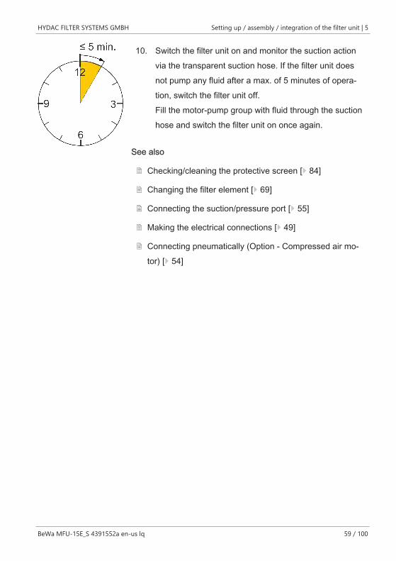
10. Switch the filter unit on and monitor the suction actionvia the transparent suction hose. If the filter unit doesnot pump any fluid after a max. of 5 minutes of opera-tion, switch the filter unit off.Fill the motor-pump group with fluid through the suctionhose and switch the filter unit on once again.
See also
2 Checking/cleaning the protective screen [} 84]
2 Changing the filter element [} 69]
2 Connecting the suction/pressure port [} 55]
2 Making the electrical connections [} 49]
2 Connecting pneumatically (Option - Compressed air mo-tor) [} 54]
6 | Operation HYDAC FILTER SYSTEMS GMBH
60 / 100 BeWa MFU-15E_S 4391552a en-us lq
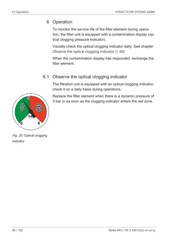
6 OperationTo monitor the service life of the filter element during opera-tion, the filter unit is equipped with a contamination display (op-tical clogging pressure indicator).
Visually check the optical clogging indicator daily. See chapterObserve the optical clogging indicator [} 60]
When the contamination display has responded, exchange thefilter element.
6.1 Observe the optical clogging indicatorThe filtration unit is equipped with an optical clogging indicator;check it on a daily basis during operations.
Fig. 20: Optical cloggingindicator
Replace the filter element when there is a dynamic pressure of3 bar or as soon as the clogging indicator enters the red zone.
HYDAC FILTER SYSTEMS GMBH Operation | 6
BeWa MFU-15E_S 4391552a en-us lq 61 / 100
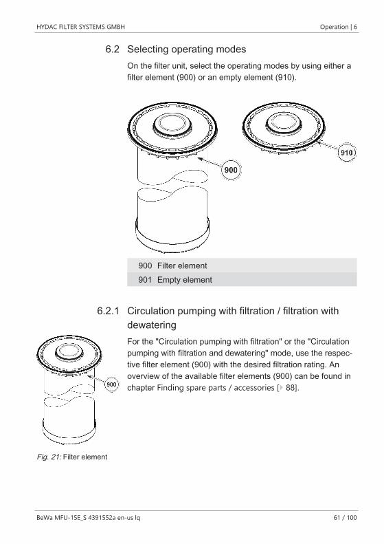
6.2 Selecting operating modesOn the filter unit, select the operating modes by using either afilter element (900) or an empty element (910).
900 Filter element901 Empty element
6.2.1 Circulation pumping with filtration / filtration withdewatering
Fig. 21: Filter element
For the "Circulation pumping with filtration" or the "Circulationpumping with filtration and dewatering" mode, use the respec-tive filter element (900) with the desired filtration rating. Anoverview of the available filter elements (900) can be found inchapter Finding spare parts / accessories [} 88].
6 | Operation HYDAC FILTER SYSTEMS GMBH
62 / 100 BeWa MFU-15E_S 4391552a en-us lq
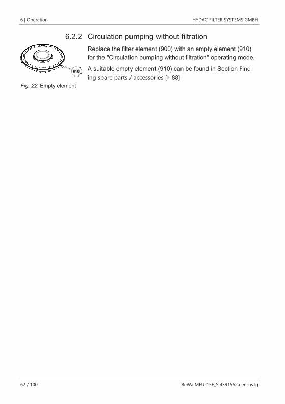
6.2.2 Circulation pumping without filtration
Fig. 22: Empty element
Replace the filter element (900) with an empty element (910)for the "Circulation pumping without filtration" operating mode.
A suitable empty element (910) can be found in Section Find-ing spare parts / accessories [} 88]
HYDAC FILTER SYSTEMS GMBH Operation | 6
BeWa MFU-15E_S 4391552a en-us lq 63 / 100
6.3 Operation with pump nozzle (optional)Observe the limited operating time during operation with theoptional pump nozzle.
NOTICEContinuous operation with closed pump nozzle
The pump will be damaged.
u Operate the filter unit with closed pump nozzle for a maxi-mum of 5 minutes.
6.4 Operation with counter (optional)While running the unit, note the limitation of the permitted vis-cosity to ≤ 200 mm²/s.
NOTICEDisallowed viscosity
Counter does not function
u When using the counter, note the permitted viscosity of≤ 200 mm²/s
7 | Rectifying errors HYDAC FILTER SYSTEMS GMBH
64 / 100 BeWa MFU-15E_S 4391552a en-us lq
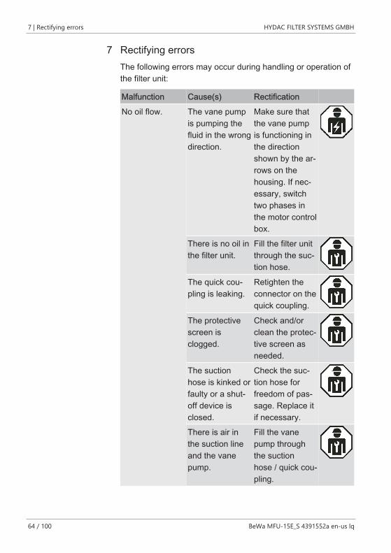
7 Rectifying errorsThe following errors may occur during handling or operation ofthe filter unit:
Malfunction Cause(s) Rectification
No oil flow. The vane pumpis pumping thefluid in the wrongdirection.
Make sure thatthe vane pumpis functioning inthe directionshown by the ar-rows on thehousing. If nec-essary, switchtwo phases inthe motor controlbox.
There is no oil inthe filter unit.
Fill the filter unitthrough the suc-tion hose.
The quick cou-pling is leaking.
Retighten theconnector on thequick coupling.
The protectivescreen isclogged.
Check and/orclean the protec-tive screen asneeded.
The suctionhose is kinked orfaulty or a shut-off device isclosed.
Check the suc-tion hose forfreedom of pas-sage. Replace itif necessary.
There is air inthe suction lineand the vanepump.
Fill the vanepump throughthe suctionhose / quick cou-pling.
HYDAC FILTER SYSTEMS GMBH Rectifying errors | 7
BeWa MFU-15E_S 4391552a en-us lq 65 / 100
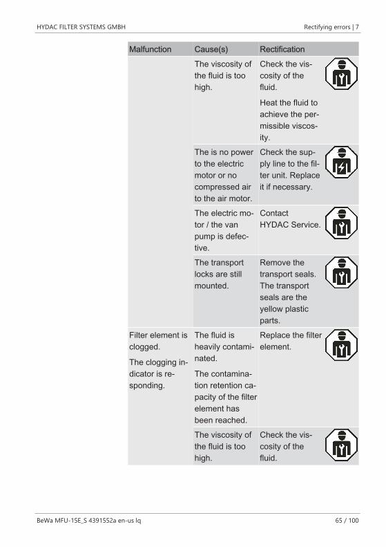
Malfunction Cause(s) Rectification
The viscosity ofthe fluid is toohigh.
Check the vis-cosity of thefluid.
Heat the fluid toachieve the per-missible viscos-ity.
The is no powerto the electricmotor or nocompressed airto the air motor.
Check the sup-ply line to the fil-ter unit. Replaceit if necessary.
The electric mo-tor / the vanpump is defec-tive.
ContactHYDAC Service.
The transportlocks are stillmounted.
Remove thetransport seals.The transportseals are theyellow plasticparts.
Filter element isclogged.
The clogging in-dicator is re-sponding.
The fluid isheavily contami-nated.
The contamina-tion retention ca-pacity of the filterelement hasbeen reached.
Replace the filterelement.
The viscosity ofthe fluid is toohigh.
Check the vis-cosity of thefluid.
7 | Rectifying errors HYDAC FILTER SYSTEMS GMBH
66 / 100 BeWa MFU-15E_S 4391552a en-us lq
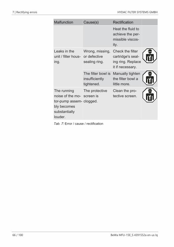
Malfunction Cause(s) Rectification
Heat the fluid toachieve the per-missible viscos-ity.
Leaks in theunit / filter hous-ing.
Wrong, missing,or defectivesealing ring.
Check the filtercartridge's seal-ing ring. Replaceit if necessary.
The filter bowl isinsufficientlytightened.
Manually tightenthe filter bowl alittle more.
The runningnoise of the mo-tor-pump assem-bly becomessubstantiallylouder.
The protectivescreen isclogged.
Clean the pro-tective screen.
Tab. 7: Error / cause / rectification
HYDAC FILTER SYSTEMS GMBH Performing maintenance | 8
BeWa MFU-15E_S 4391552a en-us lq 67 / 100
8 Performing maintenanceIn this chapter, you will find the description of the requiredmaintenance activities and the qualifications of the staffneeded to carry out these tasks.
WARNINGThe hydraulic system is under pressure during operation
Danger of bodily injury
u The hydraulic system must be depressurized before per-forming any work on the hydraulic system.
Depending on the model of the filter unit, the changing of thefilter element is different, too.
8 | Performing maintenance HYDAC FILTER SYSTEMS GMBH
68 / 100 BeWa MFU-15E_S 4391552a en-us lq
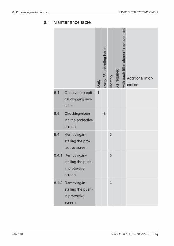
8.1 Maintenance table
Dai
lyev
ery
25 o
pera
ting
hour
sM
onth
lyAs
requ
ired
with
eac
h fil
ter e
lem
ent r
epla
cem
ent
Additional infor-mation
6.1 Observe the opti-cal clogging indi-cator
1
8.5 Checking/clean-ing the protectivescreen
3
8.4 Removing/in-stalling the pro-tective screen
3
8.4.1 Removing/in-stalling the push-in protectivescreen
3
8.4.2 Removing/in-stalling the push-in protectivescreen
3
HYDAC FILTER SYSTEMS GMBH Performing maintenance | 8
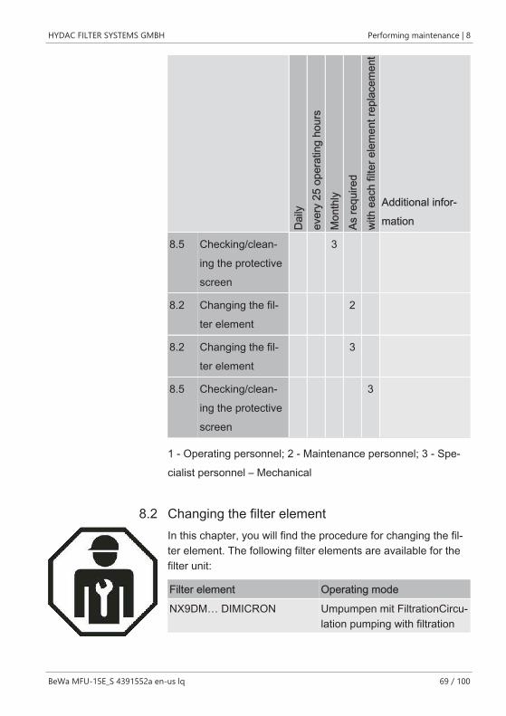
BeWa MFU-15E_S 4391552a en-us lq 69 / 100
Dai
lyev
ery
25 o
pera
ting
hour
sM
onth
lyAs
requ
ired
with
eac
h fil
ter e
lem
ent r
epla
cem
ent
Additional infor-mation
8.5 Checking/clean-ing the protectivescreen
3
8.2 Changing the fil-ter element
2
8.2 Changing the fil-ter element
3
8.5 Checking/clean-ing the protectivescreen
3
1 - Operating personnel; 2 - Maintenance personnel; 3 - Spe-cialist personnel – Mechanical
8.2 Changing the filter elementIn this chapter, you will find the procedure for changing the fil-ter element. The following filter elements are available for thefilter unit:
Filter element Operating mode
NX9DM… DIMICRON Umpumpen mit FiltrationCircu-lation pumping with filtration
8 | Performing maintenance HYDAC FILTER SYSTEMS GMBH
70 / 100 BeWa MFU-15E_S 4391552a en-us lq
Filter element Operating mode
NX9AM… AQUAMICRON Circulation pumping with filtra-tion and dewatering
NX9-xxxxx-F empty element Circulation pumping without fil-tration
Tab. 8: Overview of the filter element / type of operation
NOTICEMissing filter element/empty element
Leakages in the filter housing
u Never operate the filter unit without a filter element or anempty element inserted.
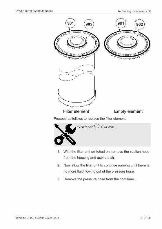
The filter element/empty element has two seal rings(901)+(902) installed. Before assembly, check for damage andalso for the correct placement of the seal rings (901)+(902).
HYDAC FILTER SYSTEMS GMBH Performing maintenance | 8
BeWa MFU-15E_S 4391552a en-us lq 71 / 100
Filter element Empty elementProceed as follows to replace the filter element:
1x Wrench = 24 mm
1. With the filter unit switched on, remove the suction hosefrom the housing and aspirate air.
2. Now allow the filter unit to continue running until there isno more fluid flowing out of the pressure hose.
3. Remove the pressure hose from the container.
8 | Performing maintenance HYDAC FILTER SYSTEMS GMBH
72 / 100 BeWa MFU-15E_S 4391552a en-us lq
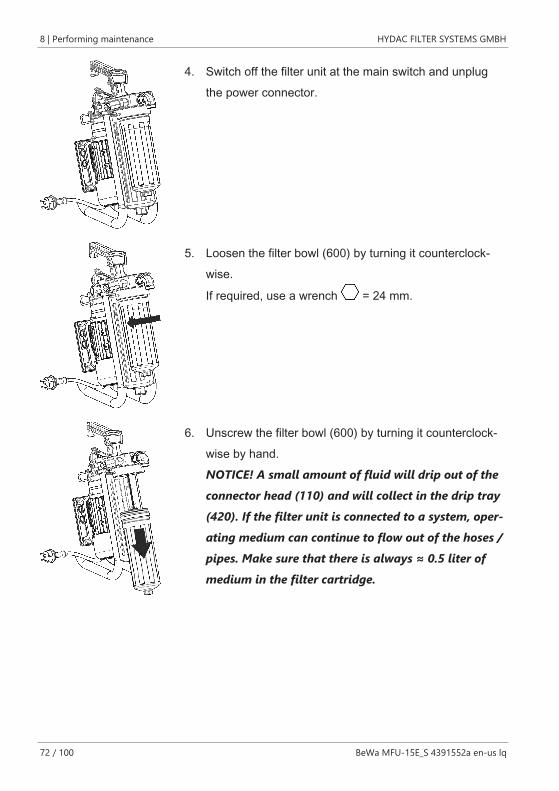
4. Switch off the filter unit at the main switch and unplugthe power connector.
5. Loosen the filter bowl (600) by turning it counterclock-wise.
If required, use a wrench = 24 mm.
6. Unscrew the filter bowl (600) by turning it counterclock-wise by hand.NOTICE! A small amount of fluid will drip out of theconnector head (110) and will collect in the drip tray(420). If the filter unit is connected to a system, oper-ating medium can continue to flow out of the hoses /pipes. Make sure that there is always ≈ 0.5 liter ofmedium in the filter cartridge.

HYDAC FILTER SYSTEMS GMBH Performing maintenance | 8
BeWa MFU-15E_S 4391552a en-us lq 73 / 100
7. Remove the used filter element.
8. Dispose of the used filter element and the residual oilvolume in an environmentally friendly manner in accor-dance with the applicable guidelines and regulations.
9. Clean the sealing surface on the connector head (11)and the filter bowl (600).Also clean the inside of the filter bowl (600).
10. Insert the new filter element or empty element into thefilter bowl. The filter bowl leaks unless a filter element orempty elements has been installed.
8 | Performing maintenance HYDAC FILTER SYSTEMS GMBH
74 / 100 BeWa MFU-15E_S 4391552a en-us lq
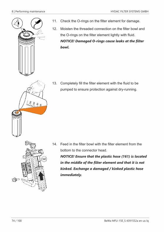
11. Check the O-rings on the filter element for damage.
12. Moisten the threaded connection on the filter bowl andthe O-rings on the filter element lightly with fluid.NOTICE! Damaged O-rings cause leaks at the filterbowl.
13. Completely fill the filter element with the fluid to bepumped to ensure protection against dry-running.
14. Feed in the filter bowl with the filter element from thebottom to the connector head.NOTICE! Ensure that the plastic hose (161) is locatedin the middle of the filter element and that it is notkinked. Exchange a damaged / kinked plastic hoseimmediately.
HYDAC FILTER SYSTEMS GMBH Performing maintenance | 8
BeWa MFU-15E_S 4391552a en-us lq 75 / 100
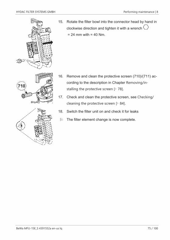
15. Rotate the filter bowl into the connector head by hand in
clockwise direction and tighten it with a wrench = 24 mm with ≈ 40 Nm.
16. Remove and clean the protective screen (710)/(711) ac-cording to the description in Chapter Removing/in-stalling the protective screen [} 78].
17. Check and clean the protective screen, see Checking/cleaning the protective screen [} 84].
18. Switch the filter unit on and check it for leaks
O The filter element change is now complete.
8 | Performing maintenance HYDAC FILTER SYSTEMS GMBH
76 / 100 BeWa MFU-15E_S 4391552a en-us lq
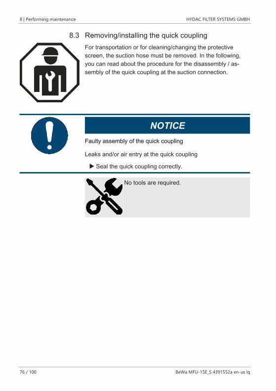
8.3 Removing/installing the quick couplingFor transportation or for cleaning/changing the protectivescreen, the suction hose must be removed. In the following,you can read about the procedure for the disassembly / as-sembly of the quick coupling at the suction connection.
NOTICEFaulty assembly of the quick coupling
Leaks and/or air entry at the quick coupling
u Seal the quick coupling correctly.
No tools are required.
HYDAC FILTER SYSTEMS GMBH Performing maintenance | 8
BeWa MFU-15E_S 4391552a en-us lq 77 / 100
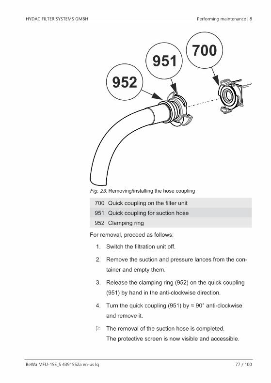
Fig. 23: Removing/installing the hose coupling
700 Quick coupling on the filter unit951 Quick coupling for suction hose952 Clamping ring
For removal, proceed as follows:
1. Switch the filtration unit off.
2. Remove the suction and pressure lances from the con-tainer and empty them.
3. Release the clamping ring (952) on the quick coupling(951) by hand in the anti-clockwise direction.
4. Turn the quick coupling (951) by ≈ 90° anti-clockwiseand remove it.
O The removal of the suction hose is completed.The protective screen is now visible and accessible.

8 | Performing maintenance HYDAC FILTER SYSTEMS GMBH
78 / 100 BeWa MFU-15E_S 4391552a en-us lq
Proceed as follows to install:
5. Attach the quick coupling (951) to the mating piece onthe filter unit (700) and rotate the quick coupling (952) by≈ 90° in clockwise direction.
6. Pull the clamping ring (952) at the quick coupling (951)by hand clockwise.NOTICE! If the clamping ring (952) is not tightenedor not sufficiently tightened, the pump will draw airthrough the quick coupling.
7. Put the filter unit into operation and check the it forleaks.
O The installation is complete.
See also
2 Finding spare parts / accessories [} 88]
8.4 Removing/installing the protective screenThe installed protective screen protects the pump from largecontaminants which could cause damage. If the uptake capac-ity of the protective screen has been reached, the volumetricflow through the filter unit reduces sharply. Clean the protec-tive screen regularly.
NOTICEOperation without the protective screen
The filter unit will be damaged or destroyed
u Never operate the filter unit without a protective screen.
HYDAC FILTER SYSTEMS GMBH Performing maintenance | 8
BeWa MFU-15E_S 4391552a en-us lq 79 / 100
The two versions of the protective screens require differentprocedures for disassembly/assembly. You will find details onthis in the subsequent chapters.
8 | Performing maintenance HYDAC FILTER SYSTEMS GMBH
80 / 100 BeWa MFU-15E_S 4391552a en-us lq
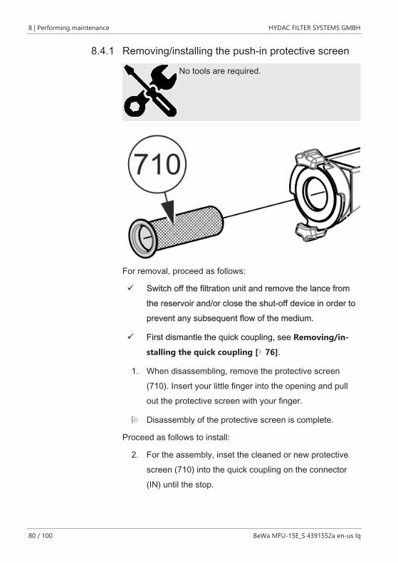
8.4.1 Removing/installing the push-in protective screen
No tools are required.
For removal, proceed as follows:
ü Switch off the filtration unit and remove the lance fromthe reservoir and/or close the shut-off device in order toprevent any subsequent flow of the medium.
ü First dismantle the quick coupling, see Removing/in-stalling the quick coupling [} 76].
1. When disassembling, remove the protective screen(710). Insert your little finger into the opening and pullout the protective screen with your finger.
O Disassembly of the protective screen is complete.
Proceed as follows to install:
2. For the assembly, inset the cleaned or new protectivescreen (710) into the quick coupling on the connector(IN) until the stop.

HYDAC FILTER SYSTEMS GMBH Performing maintenance | 8
BeWa MFU-15E_S 4391552a en-us lq 81 / 100
3. Reinstall the quick coupling, see Removing/installing thequick coupling [} 76].
O The assembly of the protective screen is complete.
8 | Performing maintenance HYDAC FILTER SYSTEMS GMBH
82 / 100 BeWa MFU-15E_S 4391552a en-us lq
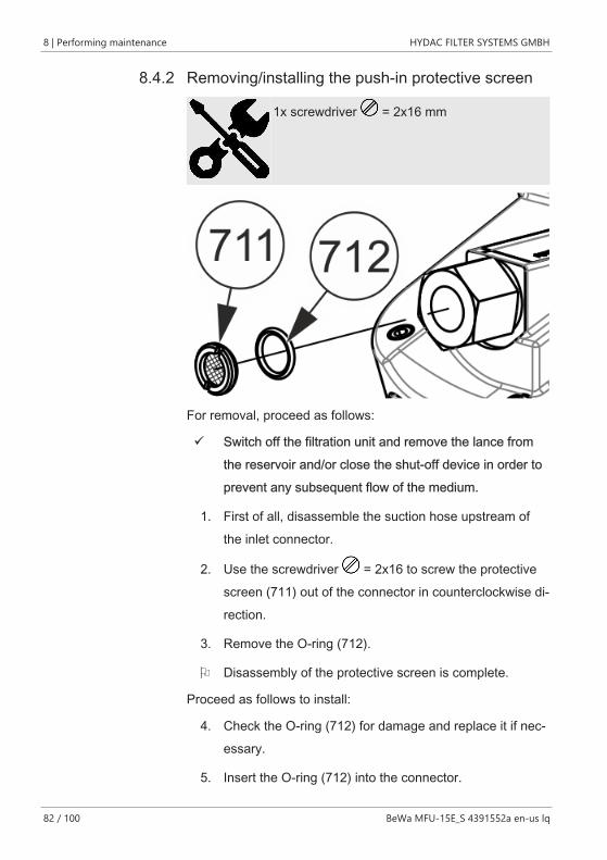
8.4.2 Removing/installing the push-in protective screen
1x screwdriver = 2x16 mm
For removal, proceed as follows:
ü Switch off the filtration unit and remove the lance fromthe reservoir and/or close the shut-off device in order toprevent any subsequent flow of the medium.
1. First of all, disassemble the suction hose upstream ofthe inlet connector.
2. Use the screwdriver = 2x16 to screw the protectivescreen (711) out of the connector in counterclockwise di-rection.
3. Remove the O-ring (712).
O Disassembly of the protective screen is complete.
Proceed as follows to install:
4. Check the O-ring (712) for damage and replace it if nec-essary.
5. Insert the O-ring (712) into the connector.
HYDAC FILTER SYSTEMS GMBH Performing maintenance | 8
BeWa MFU-15E_S 4391552a en-us lq 83 / 100
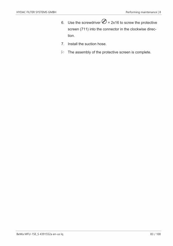
6. Use the screwdriver = 2x16 to screw the protectivescreen (711) into the connector in the clockwise direc-tion.
7. Install the suction hose.
O The assembly of the protective screen is complete.
8 | Performing maintenance HYDAC FILTER SYSTEMS GMBH
84 / 100 BeWa MFU-15E_S 4391552a en-us lq
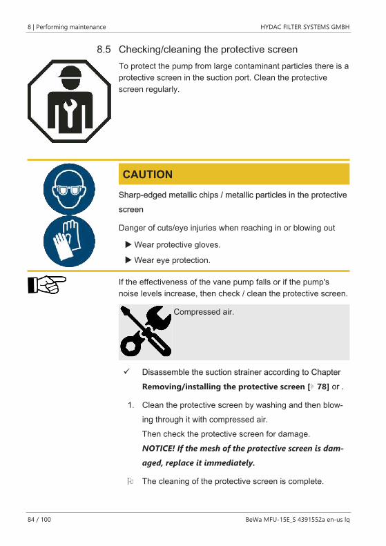
8.5 Checking/cleaning the protective screenTo protect the pump from large contaminant particles there is aprotective screen in the suction port. Clean the protectivescreen regularly.
CAUTIONSharp-edged metallic chips / metallic particles in the protectivescreen
Danger of cuts/eye injuries when reaching in or blowing out
u Wear protective gloves.
u Wear eye protection.
If the effectiveness of the vane pump falls or if the pump'snoise levels increase, then check / clean the protective screen.
Compressed air.
ü Disassemble the suction strainer according to ChapterRemoving/installing the protective screen [} 78] or .
1. Clean the protective screen by washing and then blow-ing through it with compressed air.Then check the protective screen for damage.NOTICE! If the mesh of the protective screen is dam-aged, replace it immediately.
O The cleaning of the protective screen is complete.
HYDAC FILTER SYSTEMS GMBH Performing maintenance | 8
BeWa MFU-15E_S 4391552a en-us lq 85 / 100
NOTICEDamaged protective screen
The filter unit will be damaged or destroyed
u Never operate the filter unit with a damaged or defectiveprotective screen.
9 | Removing / Disposal HYDAC FILTER SYSTEMS GMBH
86 / 100 BeWa MFU-15E_S 4391552a en-us lq
9 Removing / Disposal– Empty the product completely, including all of its compo-
nents, before decommissioning. Disconnect or remove theelectric, pneumatic or hydraulic connections.
– Dispose of the packaging material in an environmentallyfriendly manner.
– Dispose of the fluid / operating medium that has beendrained in an environmentally friendly manner.
– After dismantling the product and separating its variousmaterials into categories, dispose of all parts in an envi-ronmentally friendly manner.
HYDAC FILTER SYSTEMS GMBH Appendix |
BeWa MFU-15E_S 4391552a en-us lq 87 / 100
AppendixIn this annex, you will find supplementary information on theproduct.
Finding a Customer Service teamThe contact data such as the telephone numbers, e-mail andmailing addresses for the hotline, product support, customerservice, branch offices, service partners for servicing, repairand spare parts can be found, always updated, at our home-page www.hydac.com.
HYDAC SYSTEMS & SERVICES GMBH Friedrichsthaler Str. 15, Werk 13 66450 Neunkirchen - Heinitz
Germany
Phone: +49 6897 509 01
Fax: +49 6897 509 324
E-mail: [email protected]
Homepage: www.hydac.com
Tab. 9: Customer service in Germany
| Appendix HYDAC FILTER SYSTEMS GMBH
88 / 100 BeWa MFU-15E_S 4391552a en-us lq
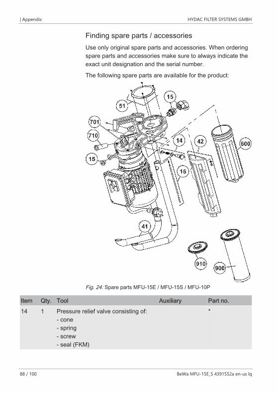
Finding spare parts / accessoriesUse only original spare parts and accessories. When orderingspare parts and accessories make sure to always indicate theexact unit designation and the serial number.
The following spare parts are available for the product:
Fig. 24: Spare parts MFU-15E / MFU-15S / MFU-10P
Item Qty. Tool Auxiliary Part no.
14 1 Pressure relief valve consisting of:- cone- spring- screw- seal (FKM)
*
HYDAC FILTER SYSTEMS GMBH Appendix |
BeWa MFU-15E_S 4391552a en-us lq 89 / 100
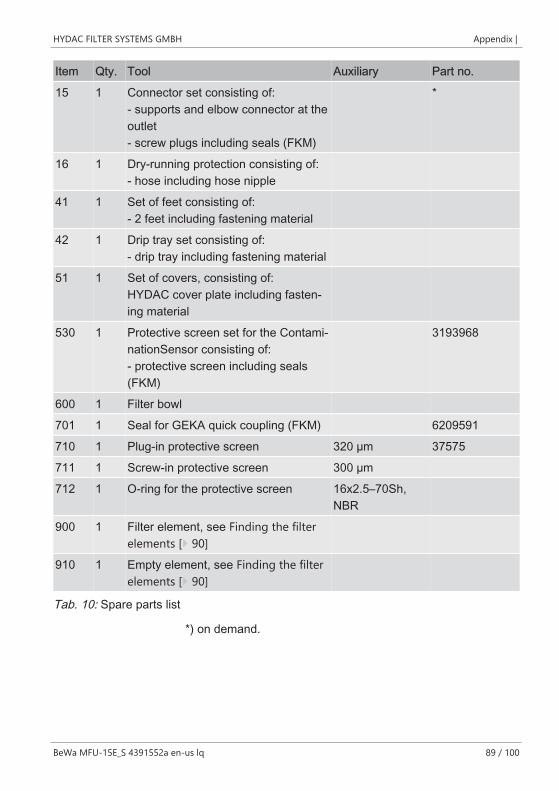
Item Qty. Tool Auxiliary Part no.
15 1 Connector set consisting of:- supports and elbow connector at theoutlet- screw plugs including seals (FKM)
*
16 1 Dry-running protection consisting of:- hose including hose nipple
41 1 Set of feet consisting of:- 2 feet including fastening material
42 1 Drip tray set consisting of:- drip tray including fastening material
51 1 Set of covers, consisting of:HYDAC cover plate including fasten-ing material
530 1 Protective screen set for the Contami-nationSensor consisting of:- protective screen including seals(FKM)
3193968
600 1 Filter bowl
701 1 Seal for GEKA quick coupling (FKM) 6209591
710 1 Plug-in protective screen 320 µm 37575
711 1 Screw-in protective screen 300 µm
712 1 O-ring for the protective screen 16x2.5–70Sh,NBR
900 1 Filter element, see Finding the filterelements [} 90]
910 1 Empty element, see Finding the filterelements [} 90]
Tab. 10: Spare parts list
*) on demand.
| Appendix HYDAC FILTER SYSTEMS GMBH
90 / 100 BeWa MFU-15E_S 4391552a en-us lq
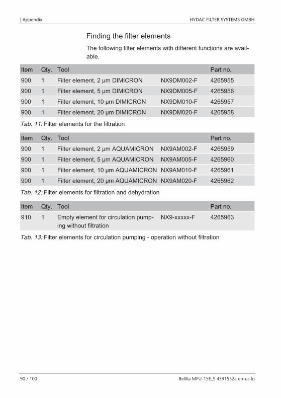
Finding the filter elementsThe following filter elements with different functions are avail-able.
Item Qty. Tool Part no.
900 1 Filter element, 2 µm DIMICRON NX9DM002-F 4265955
900 1 Filter element, 5 µm DIMICRON NX9DM005-F 4265956
900 1 Filter element, 10 µm DIMICRON NX9DM010-F 4265957
900 1 Filter element, 20 µm DIMICRON NX9DM020-F 4265958
Tab. 11: Filter elements for the filtration
Item Qty. Tool Part no.
900 1 Filter element, 2 µm AQUAMICRON NX9AM002-F 4265959
900 1 Filter element, 5 µm AQUAMICRON NX9AM005-F 4265960
900 1 Filter element, 10 µm AQUAMICRON NX9AM010-F 4265961
900 1 Filter element, 20 µm AQUAMICRON NX9AM020-F 4265962
Tab. 12: Filter elements for filtration and dehydration
Item Qty. Tool Part no.
910 1 Empty element for circulation pump-ing without filtration
NX9-xxxxx-F 4265963
Tab. 13: Filter elements for circulation pumping - operation without filtration
HYDAC FILTER SYSTEMS GMBH Appendix |
BeWa MFU-15E_S 4391552a en-us lq 91 / 100
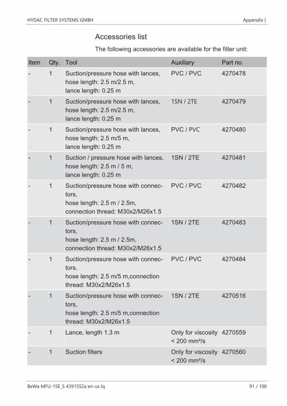
Accessories listThe following accessories are available for the filter unit:
Item Qty. Tool Auxiliary Part no.
- 1 Suction/pressure hose with lances,hose length: 2.5 m/2.5 m,lance length: 0.25 m
PVC / PVC 4270478
- 1 Suction/pressure hose with lances,hose length: 2.5 m/2.5 m,lance length: 0.25 m
1SN / 2TE 4270479
- 1 Suction/pressure hose with lances,hose length: 2.5 m/5 m,lance length: 0.25 m
PVC / PVC 4270480
- 1 Suction / pressure hose with lances, hose length: 2.5 m / 5 m,lance length: 0.25 m
1SN / 2TE 4270481
- 1 Suction/pressure hose with connec-tors,hose length: 2.5 m / 2.5m,connection thread: M30x2/M26x1.5
PVC / PVC 4270482
- 1 Suction/pressure hose with connec-tors,hose length: 2.5 m / 2.5m,connection thread: M30x2/M26x1.5
1SN / 2TE 4270483
- 1 Suction/pressure hose with connec-tors,hose length: 2.5 m/5 m,connectionthread: M30x2/M26x1.5
PVC / PVC 4270484
- 1 Suction/pressure hose with connec-tors,hose length: 2.5 m/5 m,connectionthread: M30x2/M26x1.5
1SN / 2TE 4270516
- 1 Lance, length 1.3 m Only for viscosity< 200 mm²/s
4270559
- 1 Suction filters Only for viscosity< 200 mm²/s
4270560
| Appendix HYDAC FILTER SYSTEMS GMBH
92 / 100 BeWa MFU-15E_S 4391552a en-us lq
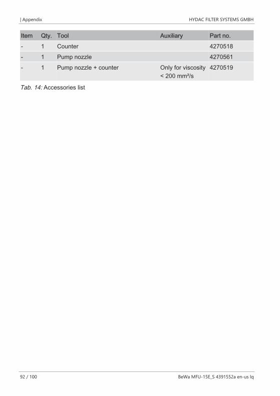
Item Qty. Tool Auxiliary Part no.
- 1 Counter 4270518
- 1 Pump nozzle 4270561
- 1 Pump nozzle + counter Only for viscosity< 200 mm²/s
4270519
Tab. 14: Accessories list
HYDAC FILTER SYSTEMS GMBH Table of Illustrations
BeWa MFU-15E_S 4391552a en-us lq 93 / 100
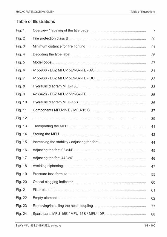
Table of Illustrations
Fig. 1 Overview / labeling of the title page ......................................................... 7
Fig. 2 Fire protection class B.............................................................................. 20
Fig. 3 Minimum distance for fire fighting............................................................. 21
Fig. 4 Decoding the type label ............................................................................ 26
Fig. 5 Model code............................................................................................... 27
Fig. 6 4155968 - EBZ MFU-15E9-Sx-FE - AC ................................................... 31
Fig. 7 4155968 - EBZ MFU-15E9-Sx-FE - DC ................................................... 32
Fig. 8 Hydraulic diagram MFU-15E .................................................................... 33
Fig. 9 4263428 - EBZ MFU-15S9-Sx-FE............................................................ 35
Fig. 10 Hydraulic diagram MFU-15S .................................................................... 36
Fig. 11 Components MFU-15 E / MFU-15 S ........................................................ 37
Fig. 12 .................................................................................................................. 39
Fig. 13 Transporting the MFU .............................................................................. 41
Fig. 14 Storing the MFU ....................................................................................... 42
Fig. 15 Increasing the stability / adjusting the feet ............................................... 44
Fig. 16 Adjusting the feet 0°->44°......................................................................... 45
Fig. 17 Adjusting the feet 44°->0°......................................................................... 46
Fig. 18 Avoiding siphoning ................................................................................... 47
Fig. 19 Pressure loss formula............................................................................... 55
Fig. 20 Optical clogging indicator ......................................................................... 60
Fig. 21 Filter element............................................................................................ 61
Fig. 22 Empty element ......................................................................................... 62
Fig. 23 Removing/installing the hose coupling ..................................................... 77
Fig. 24 Spare parts MFU-15E / MFU-15S / MFU-10P.......................................... 88
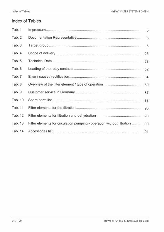
Index of Tables HYDAC FILTER SYSTEMS GMBH
94 / 100 BeWa MFU-15E_S 4391552a en-us lq
Index of Tables
Tab. 1 Impressum................................................................................................ 5
Tab. 2 Documentation Representative ................................................................ 5
Tab. 3 Target group............................................................................................. 6
Tab. 4 Scope of delivery ...................................................................................... 25
Tab. 5 Technical Data ......................................................................................... 28
Tab. 6 Loading of the relay contacts ................................................................... 52
Tab. 7 Error / cause / rectification........................................................................ 64
Tab. 8 Overview of the filter element / type of operation ..................................... 69
Tab. 9 Customer service in Germany.................................................................. 87
Tab. 10 Spare parts list ......................................................................................... 88
Tab. 11 Filter elements for the filtration ................................................................. 90
Tab. 12 Filter elements for filtration and dehydration ............................................ 90
Tab. 13 Filter elements for circulation pumping - operation without filtration ........ 90
Tab. 14 Accessories list......................................................................................... 91
HYDAC FILTER SYSTEMS GMBH Glossary
BeWa MFU-15E_S 4391552a en-us lq 95 / 100
Glossary
1SN
The 1 SN high-pressure hose has asteel mesh insert and, on the inside,is is made of oil-resistant syntheticrubber and, on the outside of wearand weather resistant synthetic rub-ber according to DIN EN 853 1SNand SAE 100 R1S.
2TE
The 2TE hydraulic hose lines havea reinforcement made of a high-strength textile mesh according toDIN EN 854.
FKM
The term "Fluororubber" (abbrevia-tion FKM according to DIN ISO1629 [earlier: FPM] and FKM ac-cording to ASTM D 1418) repre-sents an entire group of rubbers,which have, as a common charac-teristic, viniledine difluoride as oneof its monomers. (Source:Wikipedia)
General Terms and Conditions
The General Terms and Conditionsare available at our home pagewww.hydac.com -> General Termsand Conditions.
PVC
Polyvinyl chloride is a thermoplasticpolymer. As a spiral hose made oftransparent PVC, with spirals madeof galvanized spring steel andsmooth on the inside and outside.Temperature range -15°C to +60°C
Index HYDAC FILTER SYSTEMS GMBH
96 / 100 BeWa MFU-15E_S 4391552a en-us lq
Index
B
Branches 87
C
calculating pressure loss 55
D
decommissioning 86disposal 86
E
exclusion of liability 14
H
Hotline 87
I
Imprint 5
M
manufacturer 5
P
Person authorized with the documenta-tion 5
S
Service 87
Servicepartners 87siphoning effect 47stability 43Support 87
T
Terms and Conditions 14Terms of Delivery 14
W
warranty 14